Embed Size (px)
Citation preview
Chromatic aberration correction: an enhancement to the
calibration of low-cost digital dermoscopes
Paul Wighton1,2,3, Tim K. Lee1,2,3, Harvey Lui2,3, David McLean3 and M. Stella Atkins1
1School of Computing Science, Simon Fraser University, Burnaby, BC, Canada, 2Cancer Control Research and Cancer Imaging, BC Cancer Agency,Vancouver, BC, Canada and 3Department of Dermatology and Skin Science, Photomedicine Institute, University of British Columbia and Vancouver
Coastal Health Research Institute, Vancouver, BC, Canada
Background/purpose: We present a method for calibrating
low-cost digital dermoscopes that corrects for color and
inconsistent lighting and also corrects for chromatic aberra-
tion. Chromatic aberration is a form of radial distortion that
often occurs in inexpensive digital dermoscopes and cre-
ates red and blue halo-like effects on edges. Being radial in
nature, distortions due to chromatic aberration are not
constant across the image, but rather vary in both magni-
tude and direction. As a result, distortions are not only
visually distracting but could also mislead automated char-
acterization techniques.
Methods: Two low-cost dermoscopes, based on different
consumer-grade cameras, were tested. Color is corrected
by imaging a reference and applying singular value decom-
position to determine the transformation required to ensure
accurate color reproduction. Lighting is corrected by ima-
ging a uniform surface and creating lighting correction
maps. Chromatic aberration is corrected using a second-
order radial distortion model.
Results: Our results for color and lighting calibration are
consistent with previously published results, while distor-
tions due to chromatic aberration can be reduced by 42–
47% in the two systems considered.
Conclusion: The disadvantages of inexpensive dermo-
scopy can be quickly substantially mitigated with a suitable
calibration procedure.
Key words: digital dermoscopy – calibration – chromatic
aberration – color and lighting correction
& 2011 John Wiley & Sons A/SAccepted for publication 10 December 2010
WE PRESENT a method to calibrate inexpensivedigital dermoscopes, made by attaching a
traditional dermoscope to a consumer-grade di-gital camera. Such ‘low-cost’ digital dermoscopesare becoming increasingly popular as the preva-lence of dermoscopic use in the clinic increases,and the cost of digital cameras decreases. It ishoped that such systems will lead to increasedpatient care through the use of teledermatology(1) or automated diagnostic methods (2) aswell as enable the generation of a large databaseof various skin conditions to facilitate futureresearch.
The nature of such digital dermoscopes posesseveral challenges. Firstly, the illumination acrossthe field of view is not consistent, resulting inseparate areas of over- and under-exposurewithin the same image. Secondly, the color ofthe image acquired is not accurate. Commercialdigital cameras are optimized to operate undercertain typical lighting conditions (such as sun-light, incandescent light, etc.), and thus have
difficulty estimating the properties of unconven-tional light sources such as those within dermo-scopes. Moreover, consumer-grade camerasare more concerned with presenting visuallyesthetic images, rather than a faithful renditionof color per se.
These issues have been identified in the past,and calibration methods to render accurate colorand to correct inconsistent and lighting have beenproposed (3–6). These methods acquire images ofreference colors, which are used to derive trans-formations for accurate color reproduction aswell as ‘intensity maps’ to correct for variationsin lighting intensity.
In this paper, in addition to calibrating for colorand lighting, we examine a distortion effectknown as chromatic aberration, and correct forit accordingly. Chromatic aberration occurs whenthe refractive index of the optics is not constantwith respect to wavelength. This effect is illu-strated in Fig. 1. As the refractive index of thelens varies slightly with wavelength, the color of
339
Skin Research and Technology 2011; 17: 339–347Printed in Singapore �All rights reserveddoi: 10.1111/j.1600-0846.2011.00504.x
r 2011 John Wiley & Sons A/S
Skin Research and Technology
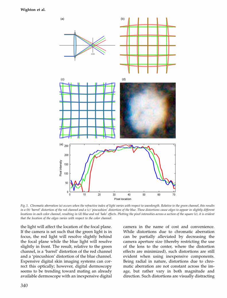
the light will affect the location of the focal plane.If the camera is set such that the green light is infocus, the red light will resolve slightly behindthe focal plane while the blue light will resolveslightly in front. The result, relative to the greenchannel, is a ‘barrel’ distortion of the red channeland a ‘pincushion’ distortion of the blue channel.Expensive digital skin imaging systems can cor-rect this optically; however, digital dermoscopyseems to be trending toward mating an alreadyavailable dermoscope with an inexpensive digital
camera in the name of cost and convenience.While distortions due to chromatic aberrationcan be partially alleviated by decreasing thecamera aperture size (thereby restricting the useof the lens to the center, where the distortioneffects are minimized), such distortions are stillevident when using inexpensive components.Being radial in nature, distortions due to chro-matic aberration are not constant across the im-age, but rather vary in both magnitude anddirection. Such distortions are visually distracting
Fig. 1. Chromatic aberration (a) occurs when the refractive index of light varies with respect to wavelength. Relative to the green channel, this results
in a (b) ‘barrel’ distortion of the red channel and a (c) ‘pincushion’ distortion of the blue. These distortions cause edges to appear in slightly different
locations in each color channel, resulting in (d) blue and red ‘halo’ effects. Plotting the pixel intensities across a section of the square (e), it is evident
that the location of the edges varies with respect to the color channel.
340
Wighton et al.
and possibly clinically confounding. Further-more, these distortions could also mislead auto-mated characterization techniques (such as theautomated identification of occluding hair ordermoscopic structures). For example, the var-iance of color within a lesion is an extremelyimportant feature in both clinical as well asautomated diagnosis (2), the accuracy of whichwould certainly be curbed by the introduction ofspurious shades of red and blue. As a result, asoftware-based method of chromatic aberrationcorrection is becoming increasingly necessary. Wepresent a calibration method that not only cor-rects for inconsistent lighting and ensures accu-rate color reproduction but also corrects forchromatic aberration.
Methods
The imaging systemsWe use two digital dermoscope systems in orderto design and validate our calibration method.The first is a Dermlite II Pro (3Gen LLC, San JuanCapistrano, CA, USA) attached to a CanonPowershot G9 (Canon Inc., Tokyo, Japan) digitalcamera using a custom lens adapter (Lensmate,Gig Harbor, WA, USA) and standard steppingrings. A custom light shroud was machined andattached to the end of the dermoscope so that noambient lighting would be present in the images.Images are acquired in the ‘raw’ mode with aresolution of 4000� 3000 pixels. The spatial re-solution is approximately 0.0073 mm2. The sec-ond system is a Dermlite II Pro attached to a SonyCybershot DSC-W300 (Sony Corporation, Tokyo,Japan) using a custom lens adapter. The Sonycamera acquires jpeg images with a resolution of4224� 3168 pixels and an approximate spatialresolution of 0.0063 mm2. We refer to these sys-tems as the ‘Canon system’ and the ‘Sony sys-tem,’ respectively. As the magnitude of chromaticaberration is related to the aperture size of thecamera, both cameras were set to use the smallestpossible aperture size. The Canon camera para-meters were set to: iso 100, shutter 1/30, f/5.0and the Sony camera parameters were set to: iso100, shutter 1/40, f/5.6.
A 24-patch color chart (X-Rite, Grand Rapids,MI, USA) and a black and white checkeredpattern are used to calibrate the system. Thefreely available, open-source tool dcraw (7) isused to process the raw sensor data and convertit to uncalibrated CIE XYZ colorspace (8). An
S2000 spectrometer (Ocean Optics, Dunedin, FL,USA) was used to measure the reflectance curveof each color patch of the color chart, which actsas the ground truth color measurement.
A note on colorspacesThree colorspaces are used throughout this pa-per. The first is CIE XYZ, which, when properlycalibrated, is linear with respect to the sensitiv-ities of the retinal cone cells in a standard humanobserver. When uncalibrated (as is when dcraw isused to convert from ‘raw’ format), it is linearwith respect to the sensitivities of the camera’sCCD. Both color and lighting corrections areperformed in this space. The second colorspaceused is sRGB, which is a standardized colorspaceused for display under typical viewing condi-tions. It is non-linear with respect to CIE XYZbecause of the inclusion of a ‘gamma correction’step, which compensates for the non-linearities ofdisplay devices. Because gamma correction isimplicit in sRGB, we do not perform an explicitgamma correction step as in (4). Chromaticaberration is performed in this space and allimages throughout this paper are presented insRGB. The third colorspace used is CIE L�a�b�,which is an approximately perceptually uniformcolorspace, but non-linear with respect toboth XYZ and sRGB. This colorspace is used tocompare our method with previous results (3).Conversions between these three colorspaces arewell defined (8).
Color calibrationGiven a color c 5 [x y z]T in the camera’s uncali-brated CIE XYZ colorspace, we transform it intothe calibrated colorspace c� ¼ ½x� y� z��Tvia a 3� 3color transformation matrix, M:
c� ¼Mc
To compute M, we measure each of the 24patches of the color chart using the dermoscopeas well as the spectrometer. An image of eachcolor patch is acquired using the dermoscope andis converted to an uncalibrated CIE XYZ space.The color of each patch is calculated by averagingover a small area in the center of the image wherethe lighting is the strongest. These uncalibratedcolor values are stored in a 24� 3 matrix C. Next,the spectral reflectance curves of each of the 24color patches are measured using a spectrometer.These reflectance curves are then multipliedby the three CIE standard observer matching
341
Chromatic aberration correction
functions (8), which approximate the absorptionspectra of the short, medium and long cones of thehuman retina, respectively. The resulting spectraare then integrated, yielding a point in the CIEXYZ space. These calibrated color values arestored in a 24� 3 matrix C�: It then follows that
C� ¼MC
and the least squares solution for M is obtained viasingular value decomposition
M ¼ ðCTCÞ�1CTC�
Once the transformation matrix M is computed,acquired images are transformed to the CIE XYZspace by multiplying uncalibrated color values byM. An example of this is shown in Fig. 2.
Lighting calibrationAfter calibrating for color, the colors in the centerof the images are now much more accurate;however, the intensity of the lighting is notconsistent across the image and must there-fore be accounted for. We correct for this incon-sistency by creating an illumination correctionmap (4).
To create this map, we consider the white patchon the color chart. Gaussian blurring is applied tothe acquired image of this patch to remove anyhigh-frequency variations (such as imperfectionsin the surface, dust, etc.) and the result for eachchannel is stored in the matrix XW, YW and ZW,respectively. We then relate these acquired valuesto the ground truth values obtained using thespectrometer data (XS, YS, ZS). The correctionmap for the X channel (XC) is then computed asfollows:
XC ¼XS
XW
YC and ZC are similarly computed. Newlyacquired images are then corrected by pairwisemultiplication with this correction map.
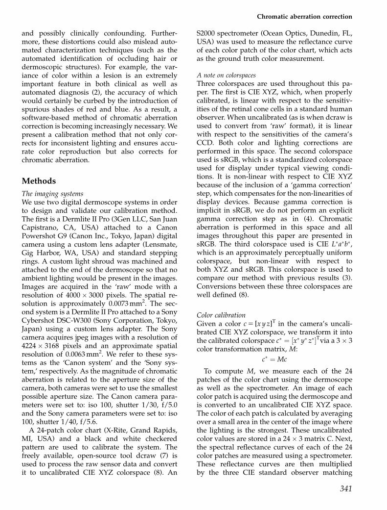
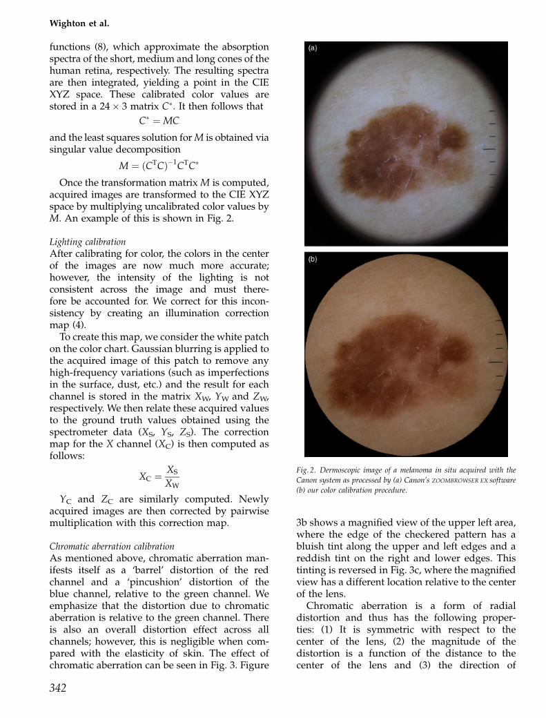
Chromatic aberration calibrationAs mentioned above, chromatic aberration man-ifests itself as a ‘barrel’ distortion of the redchannel and a ‘pincushion’ distortion of theblue channel, relative to the green channel. Weemphasize that the distortion due to chromaticaberration is relative to the green channel. Thereis also an overall distortion effect across allchannels; however, this is negligible when com-pared with the elasticity of skin. The effect ofchromatic aberration can be seen in Fig. 3. Figure
3b shows a magnified view of the upper left area,where the edge of the checkered pattern has abluish tint along the upper and left edges and areddish tint on the right and lower edges. Thistinting is reversed in Fig. 3c, where the magnifiedview has a different location relative to the centerof the lens.
Chromatic aberration is a form of radialdistortion and thus has the following proper-ties: (1) It is symmetric with respect to thecenter of the lens, (2) the magnitude of thedistortion is a function of the distance to thecenter of the lens and (3) the direction of
Fig. 2. Dermoscopic image of a melanoma in situ acquired with the
Canon system as processed by (a) Canon’s ZOOMBROWSER EX software
(b) our color calibration procedure.
342
Wighton et al.
the distortion for any given point is radial,that is, along the line joining it to the center ofthe lens. We can therefore correct chromaticaberration by using a radial distortion model (9)once we have determined (1) the center of thelens in image coordinates and (2) the relationshipbetween the magnitude of the distortion and thedistance to the lens center. Both tasks can beaccomplished by imaging a black and whitecheckered pattern.
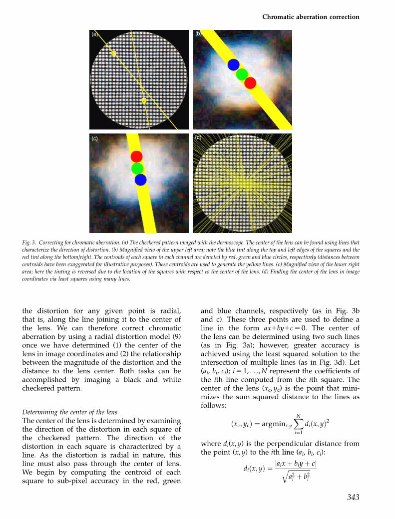
Determining the center of the lensThe center of the lens is determined by examiningthe direction of the distortion in each square ofthe checkered pattern. The direction of thedistortion in each square is characterized by aline. As the distortion is radial in nature, thisline must also pass through the center of lens.We begin by computing the centroid of eachsquare to sub-pixel accuracy in the red, green
and blue channels, respectively (as in Fig. 3band c). These three points are used to define aline in the form ax1by1c 5 0. The center ofthe lens can be determined using two such lines(as in Fig. 3a); however, greater accuracy isachieved using the least squared solution to theintersection of multiple lines (as in Fig. 3d). Let(ai, bi, ci); i 5 1, . . ., N represent the coefficients ofthe ith line computed from the ith square. Thecenter of the lens (xc, yc) is the point that mini-mizes the sum squared distance to the lines asfollows:
ðxc; ycÞ ¼ argminx;y
XN
i¼1
diðx; yÞ2
where di(x, y) is the perpendicular distance fromthe point (x, y) to the ith line (ai, bi, ci):
diðx; yÞ ¼jaixþ biyþ cjffiffiffiffiffiffiffiffiffiffiffiffiffiffi
a2i þ b2
i
q
Fig. 3. Correcting for chromatic aberration. (a) The checkered pattern imaged with the dermoscope. The center of the lens can be found using lines that
characterize the direction of distortion. (b) Magnified view of the upper left area; note the blue tint along the top and left edges of the squares and the
red tint along the bottom/right. The centroids of each square in each channel are denoted by red, green and blue circles, respectively (distances between
centroids have been exaggerated for illustrative purposes). These centroids are used to generate the yellow lines. (c) Magnified view of the lower right
area; here the tinting is reversed due to the location of the squares with respect to the center of the lens. (d) Finding the center of the lens in image
coordinates via least squares using many lines.
343
Chromatic aberration correction
for which the closed-form solution is derived:
yc ¼PN
i¼1 biciPN
i¼1 a2i �
PNi¼1 aici
PNi¼1 aibi
PNi¼1 aibi
� �2�PN
i¼1 b2i
PNi¼1 a2
i
xc ¼�yc
PNi¼1 aibi �
PNi¼1 aiciPN
i¼1 a2i
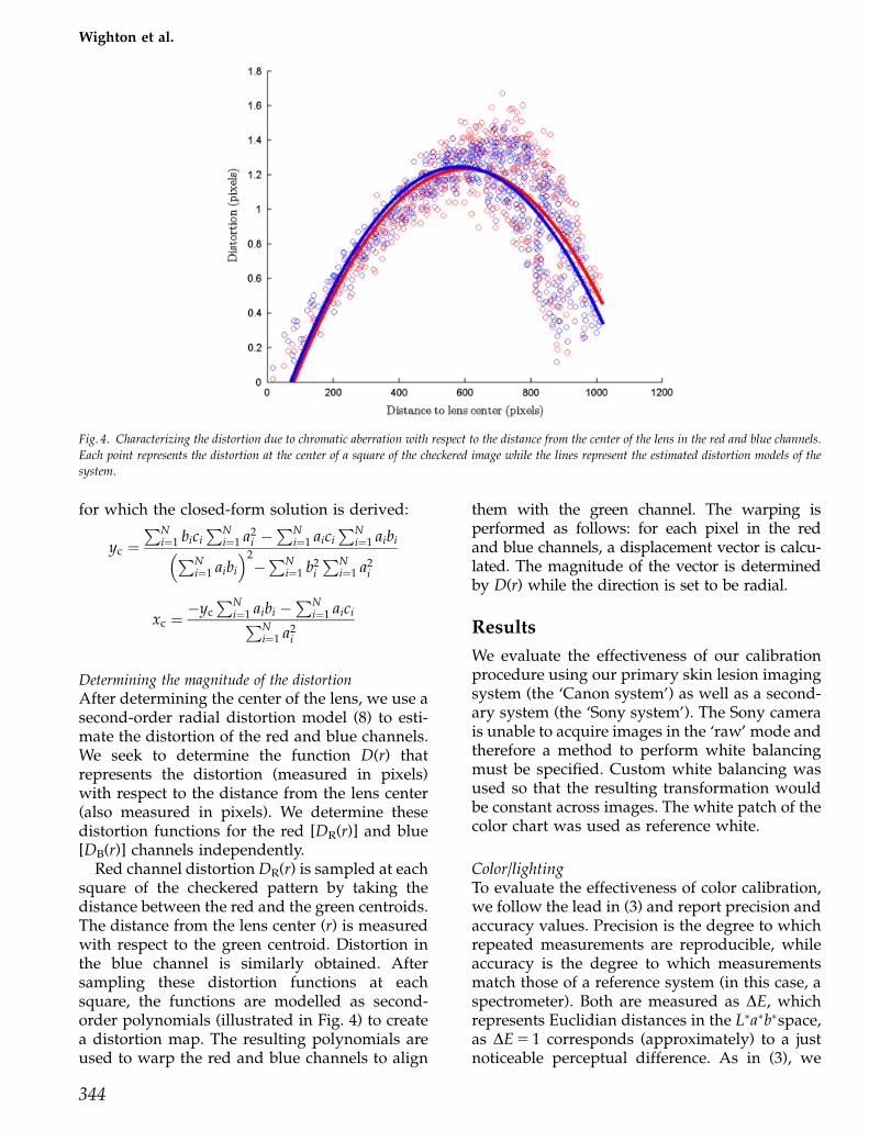
Determining the magnitude of the distortionAfter determining the center of the lens, we use asecond-order radial distortion model (8) to esti-mate the distortion of the red and blue channels.We seek to determine the function D(r) thatrepresents the distortion (measured in pixels)with respect to the distance from the lens center(also measured in pixels). We determine thesedistortion functions for the red [DR(r)] and blue[DB(r)] channels independently.
Red channel distortion DR(r) is sampled at eachsquare of the checkered pattern by taking thedistance between the red and the green centroids.The distance from the lens center (r) is measuredwith respect to the green centroid. Distortion inthe blue channel is similarly obtained. Aftersampling these distortion functions at eachsquare, the functions are modelled as second-order polynomials (illustrated in Fig. 4) to createa distortion map. The resulting polynomials areused to warp the red and blue channels to align
them with the green channel. The warping isperformed as follows: for each pixel in the redand blue channels, a displacement vector is calcu-lated. The magnitude of the vector is determinedby D(r) while the direction is set to be radial.
Results
We evaluate the effectiveness of our calibrationprocedure using our primary skin lesion imagingsystem (the ‘Canon system’) as well as a second-ary system (the ‘Sony system’). The Sony camerais unable to acquire images in the ‘raw’ mode andtherefore a method to perform white balancingmust be specified. Custom white balancing wasused so that the resulting transformation wouldbe constant across images. The white patch of thecolor chart was used as reference white.
Color/lightingTo evaluate the effectiveness of color calibration,we follow the lead in (3) and report precision andaccuracy values. Precision is the degree to whichrepeated measurements are reproducible, whileaccuracy is the degree to which measurementsmatch those of a reference system (in this case, aspectrometer). Both are measured as DE, whichrepresents Euclidian distances in the L�a�b�space,as DE 5 1 corresponds (approximately) to a justnoticeable perceptual difference. As in (3), we
Fig. 4. Characterizing the distortion due to chromatic aberration with respect to the distance from the center of the lens in the red and blue channels.
Each point represents the distortion at the center of a square of the checkered image while the lines represent the estimated distortion models of the
system.
344
Wighton et al.
report the mean and maximum values. Table 1summarizes the results.
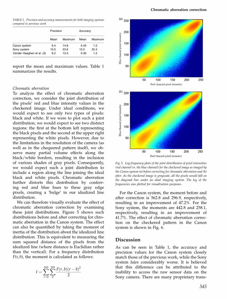
Chromatic aberrationTo analyze the effect of chromatic aberrationcorrection, we consider the joint distribution ofthe pixels’ red and blue intensity values in thecheckered image. Under ideal conditions, wewould expect to see only two types of pixels:black and white. If we were to plot such a jointdistribution, we would expect to see two distinctregions: the first at the bottom left representingthe black pixels and the second at the upper rightrepresenting the white pixels. However, due tothe limitations in the resolution of the camera (aswell as in the chequered pattern itself), we ob-serve many partial volume effects along theblack/white borders, resulting in the inclusionof various shades of gray pixels. Consequently,we would expect such a joint distribution toinclude a region along the line joining the idealblack and white pixels. Chromatic aberrationfurther distorts this distribution by conferr-ing red and blue hues to these gray edgepixels, creating a ‘bulge’ in our idealized linedistribution.
We can therefore visually evaluate the effect ofchromatic aberration correction by examiningthese joint distributions. Figure 5 shows suchdistributions before and after correcting for chro-matic aberration in the Canon system. The effectcan also be quantified by taking the moment ofinertia of the distribution about the idealized linedistribution. This is equivalent to measuring thesum squared distance of the pixels from theidealized line (where distance is Euclidian ratherthan the vertical). For a frequency distributionF(r, b), the moment is calculated as follows:
I ¼X255
r¼0
X255
0
Fðr; bÞðr� bÞ2
2
For the Canon system, the moment before andafter correction is 562.8 and 296.9, respectively,resulting in an improvement of 47.2%. For theSony system, the moments are 442.8 and 258.1,respectively, resulting in an improvement of41.7%. The effect of chromatic aberration correc-tion on the checkered pattern in the Canonsystem is shown in Fig. 6.
Discussion
As can be seen in Table 1, the accuracy andprecision values for the Canon system closelymatch those of the previous work, while the Sonysystem fairs considerably worse. It is believedthat this difference can be attributed to theinability to access the raw sensor data on theSony camera. There are many proprietary trans-
TABLE 1. Precision and accuracy measurements for both imaging systemscompared to previous work
Precision Accuracy
Mean Maximum Mean Maximum
Canon system 6.4 14.8 0.43 1.2
Sony system 10.0 23.6 10.2 22.4
Vander Haeghen et al. (3) 6.2 13.3 0.30 1.2
Fig. 5. Log-frequency plots of the joint distribution of pixel intensities
(red channel vs. the blue channel) for the checkered image as imaged by
the Canon system (a) before correcting for chromatic aberration and (b)
after. As the checkered image is grayscale, all the pixels would fall on
the diagonal line under an ideal imaging system. The log of the
frequencies was plotted for visualization purposes.
345
Chromatic aberration correction
formations that consumer cameras perform onraw sensor data in the name of esthetics whenconverting to a standard image format such as tiffor jpeg. If these transformations are constant acrossimages, then under certain conditions, it is possiblethat calibration can undo them. If, however, thesetransformations are not constant across images(e.g. contrast normalization), then it is impossiblefor a calibration method to correct for this. It issuspected that the relatively poor precision andaccuracy observed in the Sony system is due tosuch transformations. This gives strong motivationfor ensuring that a camera has raw mode capabil-ities if it is to be used in a setting where accuratecolor reproduction is important.
Chromatic aberration is an interesting phe-nomenon that has hitherto gone unstudied in
digital dermoscopy. While expensive optical sys-tems are designed to mitigate chromaticaberration optically, the growing tendency tocreate low-cost ad hoc digital dermoscopessuggests that this will only become moreof a concern in the future. As chromaticaberration can be partially managed via camerasettings, we recommend always using theminimum aperture size with any digitaldermoscope that uses a consumer-grade camera.Additionally, we show that chromatic aberrationcan be further mitigated via software-basedcalibration.
Furthermore, it may be possible to exploitchromatic aberration for beneficial ends, such asimproving the automatic detection of hair indermoscopic images (10).
References
1. Perednia DA, Brown NA. Teleder-matology: one application of tele-medicine. Bull Med Libr Assoc1995; 83: 42–47.
2. Day GR, Barbour RH. Automatedmelanoma diagnosis: where are
we at? Skin Res Technol 2000; 6:1–5.
3. Vander Haeghen Y, Naeyaert JM,Lemahieu I, Philips W. An imagingsystem with calibrated color imageacquisition for use in dermatology.IEEE Trans Med Imaging 2000; 19:722–730.
4. Grana C, Pellacani G, Seidenari S.Practical color calibration for der-moscopy, applied to a digital epilu-minescence microscope. Skin ResTechnol 2005; 11: 242–247.
5. Maglogiannis I. Design and imple-mentation of a calibrated store andforward imaging system for teleder-
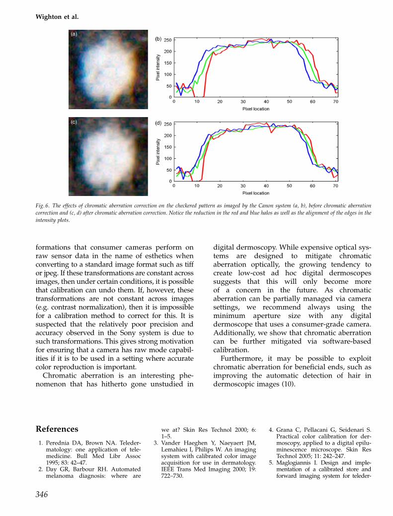
Fig. 6. The effects of chromatic aberration correction on the checkered pattern as imaged by the Canon system (a, b), before chromatic aberration
correction and (c, d) after chromatic aberration correction. Notice the reduction in the red and blue halos as well as the alignment of the edges in the
intensity plots.
346
Wighton et al.

matology. J Med Syst 2004; 28: 455–467.
6. Spaces C. Consistent cutaneousimaging with commercial digitalcameras. Arch Dermatol 2006; 142:42–46.
7. Coffin D. Dcraw software. 2008. Avail-able at http://www.cybercom.net/� dcoffin/dcraw/ (accessed March
23, 2010).
8. Ebner M. Color constancy. NewYork: Wiley, 2007.
9. Devernay F, Faugeras O. Automaticcalibration and removal of distor-tion from scenes of structured en-vironments. Proc Soc Proc Inst Eng1995; 2567: 62–72.
10. Wighton P, Lee TK, Atkins MS. Der-mascopic hair disocclusion using in-painting. Proc Soc Proc Inst Eng2008; 6914: 691427–6914278.
Address:Tim K. LeeCancer Control Research and Cancer Ima-gingBC Cancer Agency675 West 10th AvenueVancouver, BCCanada V5Z 1L3e-mail: [email protected]
347
Chromatic aberration correction