Embed Size (px)
Citation preview
Caving 2018 – Y Potvin and J Jakubec (eds) © 2018 Australian Centre for Geomechanics, Perth, ISBN 978-0-9924810-9-4
Caving 2018, Vancouver, Canada 385
Chuquicamata underground mine design: the simplification
of the ore handling system of Lift 1
P Paredes Codelco, Chile
T Leaño Codelco, Chile
L Jauriat Codelco, Chile
Abstract
The ore handling system layout plays a fundamental role in cave mining projects, not only because it is one of the main drivers in the production capacity and reliability of the mining system, but also because it is a fundamental variable in the footprint’s development time and cost (Paredes et al. 2016).
In terms of ore handling system definition, the governing paradigm in Codelco’s projects has been the productivity maximisation through the optimisation of load–haul–dump unit (LHD) tramming distances. This has resulted in layout designs that solve the productive-effectiveness problem by shortening the LHD tramming distance by introducing orepasses inside the footprint area.
Following this principle, the original macro block design of the Chuquicamata Underground Mine Project (PMCHS) considered an ore handling system layout based on the maximisation of operational flexibility. In this design, LHDs dumped into orepasses located inside the footprint area, transferring the ore into crusher chambers located below the production level, where ore was crushed and then conveyed to surface. This resulted in a very flexible layout for the operation, but at the same time, implied the execution of a large amount of vertical and major infrastructure excavations, as well as the assembling, commissioning and operation of a large amount of mechanical equipment for the mine.
The caving industry today has proven the effectiveness of simpler layouts based on direct tipping by LHDs to crushers positioned in the periphery of the footprint. The productivity competitiveness of these type of layouts is based on the use of intensive preconditioning and larger LHD and crushing equipment (Manca 2013; Flores 2014; Paredes et al. 2016).
A first approach in improving Chuquicamata’s mine design with a simpler mine layout was performed in 2015 (Paredes et al. 2016), but for a limited experimental area. Then, during 2017, in order to improve the whole project’s economics by reducing development time and cost (with a simpler mine design), and in parallel with the development of the initial macro blocks, the PMCHS ore handling system for Lift 1 was re-engineered, aiming to capture the latest improvements in existing technology, such as the application of large-scale rock mass engineering, with higher capacity loaders and crushers able to process larger sized boulders tipped directly from large bucket loaders. This paper presents the main considerations and results for the transition from a traditional LHD–orepass layout to a LHD–peripheral crusher-based layout.
Keywords: mine design, ore handling system, block caving, caving projects
1 Introduction
1.1 Chuquicamata underground mine overview
Supercaves (Araneda 2015; Flores 2014) is the name of the new generation of large block/panel caving mines, among which are Oyu Tolgoi, Grasberg Block Cave, Cadia East, Wafi-Golpu, El Teniente New Mine Level and the Chuquicamata underground mine. Given the current mining context, supercaves will have to face several challenges from technical, managerial, communitarian and social aspects, in order to ensure
https://papers.acg.uwa.edu.au/p/1815_27_Paredes/
Chuquicamata underground mine design: the simplification P Paredes et al. of the ore handling system of Lift 1
386 Caving 2018, Vancouver, Canada
the profitability and sustainability of the mining companies that own them, in the context of the deepening or depleting of the ore bodies that surround them.
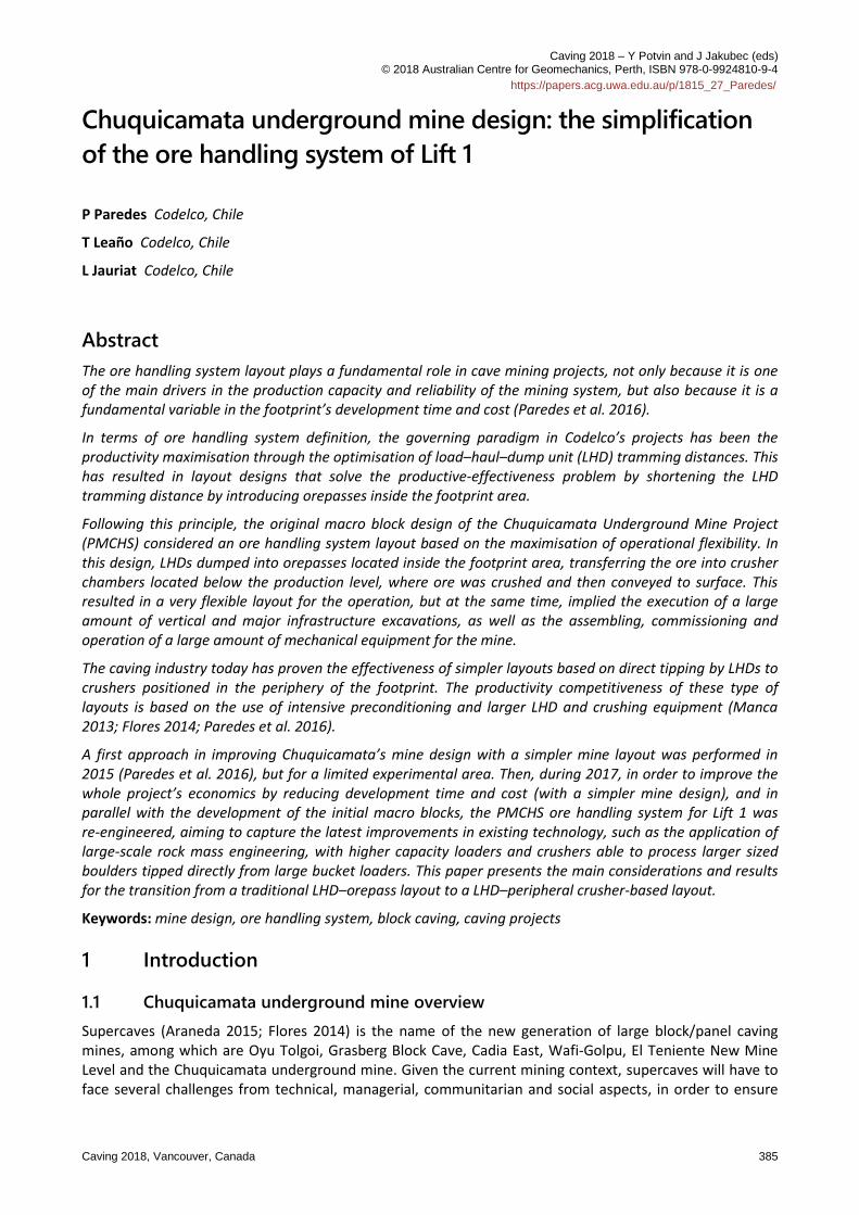
The Chuquicamata Underground Mine Project (PMCHS) consists of the transformation of the Chuquicamata historical open pit to a large-scale underground block caving mine that considers the profitable extraction of 1,760 Mt of ore consisting of 0.7% of copper and 512 ppm of molybdenum at a mining rate of 140,000 tpd, achieved after seven years of ramp-up, over 38 years. The original definition of the PMCHS contemplated four levels, with up to two levels operating simultaneously, five main air intake tunnels, two main air exhaust shafts, a main access decline, and a main conveyor incline through which the whole mine production will be transported to surface (Figure 1). The first lift is located 200 m below the pit bottom, and will mine ore columns of up to 400 m high (Paredes et al. 2016).
Figure 1 Chuquicamata underground mine original configuration
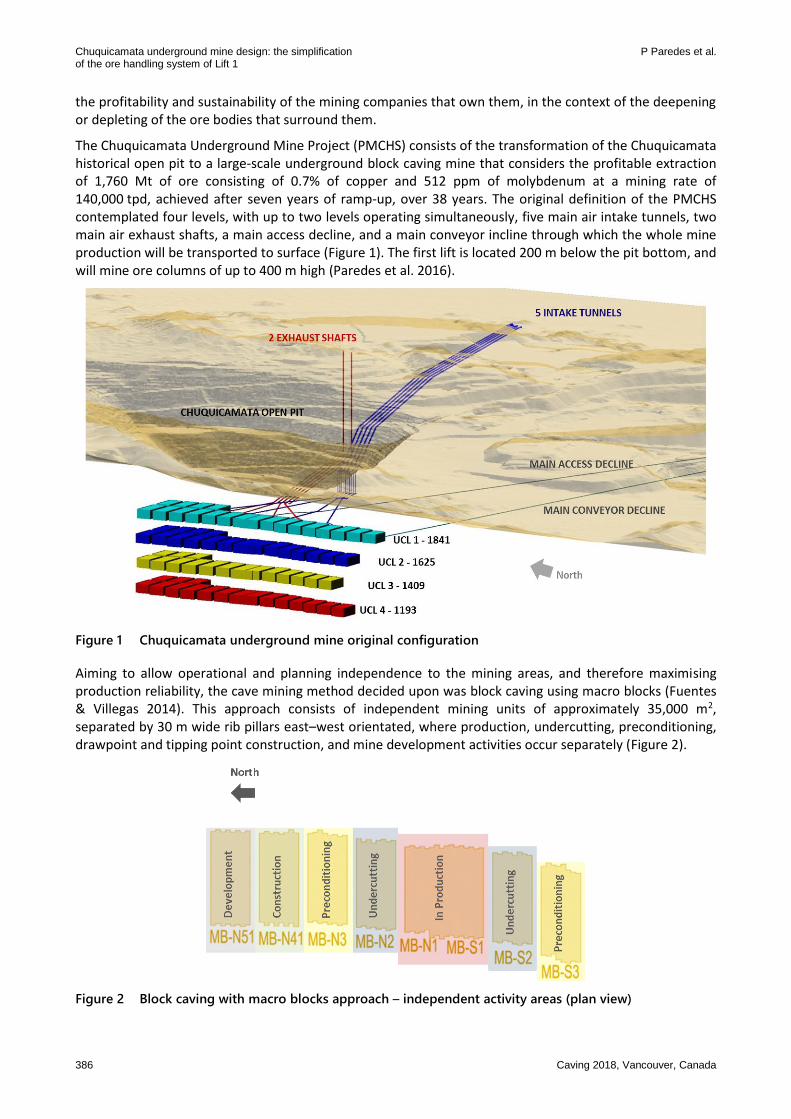
Aiming to allow operational and planning independence to the mining areas, and therefore maximising production reliability, the cave mining method decided upon was block caving using macro blocks (Fuentes & Villegas 2014). This approach consists of independent mining units of approximately 35,000 m2, separated by 30 m wide rib pillars east–west orientated, where production, undercutting, preconditioning, drawpoint and tipping point construction, and mine development activities occur separately (Figure 2).
Figure 2 Block caving with macro blocks approach – independent activity areas (plan view)
Mine planning
Caving 2018, Vancouver, Canada 387
1.2 Chuquicamata underground mine macro blocks original design
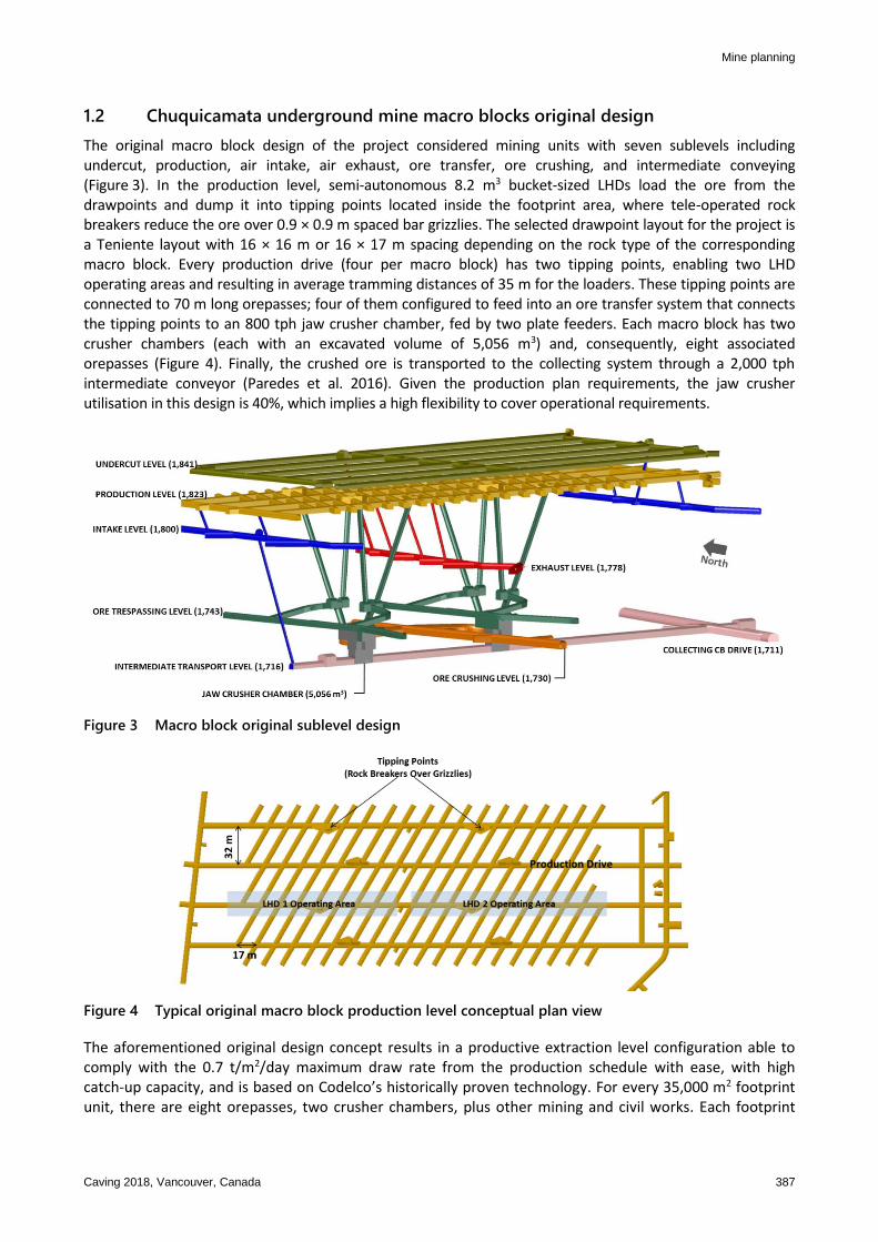
The original macro block design of the project considered mining units with seven sublevels including undercut, production, air intake, air exhaust, ore transfer, ore crushing, and intermediate conveying (Figure 3). In the production level, semi-autonomous 8.2 m3 bucket-sized LHDs load the ore from the drawpoints and dump it into tipping points located inside the footprint area, where tele-operated rock breakers reduce the ore over 0.9 × 0.9 m spaced bar grizzlies. The selected drawpoint layout for the project is a Teniente layout with 16 × 16 m or 16 × 17 m spacing depending on the rock type of the corresponding macro block. Every production drive (four per macro block) has two tipping points, enabling two LHD operating areas and resulting in average tramming distances of 35 m for the loaders. These tipping points are connected to 70 m long orepasses; four of them configured to feed into an ore transfer system that connects the tipping points to an 800 tph jaw crusher chamber, fed by two plate feeders. Each macro block has two crusher chambers (each with an excavated volume of 5,056 m3) and, consequently, eight associated orepasses (Figure 4). Finally, the crushed ore is transported to the collecting system through a 2,000 tph intermediate conveyor (Paredes et al. 2016). Given the production plan requirements, the jaw crusher utilisation in this design is 40%, which implies a high flexibility to cover operational requirements.
Figure 3 Macro block original sublevel design
Figure 4 Typical original macro block production level conceptual plan view
The aforementioned original design concept results in a productive extraction level configuration able to comply with the 0.7 t/m2/day maximum draw rate from the production schedule with ease, with high catch-up capacity, and is based on Codelco’s historically proven technology. For every 35,000 m2 footprint unit, there are eight orepasses, two crusher chambers, plus other mining and civil works. Each footprint
Chuquicamata underground mine design: the simplification P Paredes et al. of the ore handling system of Lift 1
388 Caving 2018, Vancouver, Canada
unit takes approximately 45 months from the beginning of macro block development, until its first drawbell is blasted, with considerable development cost and complexity (Paredes et al. 2016).
1.3 Need for simplification
Due to several reasons, by the end of 2016, the project undertook a reformulation process in which the technical team was challenged to engineer an alternative mine design that would improve the project’s net present value. This improvement in net present value is achieved by reducing the macro blocks’ development time and cost, concurrent with the large-scale footprint development being executed.
Taking into account current industry practices, where incremental technological changes (as described by Flores 2014) have enabled simpler layouts, such as LHD direct tipping to the crusher, to achieve higher production rates despite the larger tramming distances, the re-engineering process of Chuquicamata underground mine’s mining system was based on the successful experiences with this type of layout.
The following describes the main considerations and results from the transition from a traditional LHD–orepass layout to a LHD–peripheral crusher-based layout, and the current progress in the excavation development of the initial macro blocks, in the context of the ongoing execution of Codelco’s largest structural project.
2 Simple is better – current caving industry practices
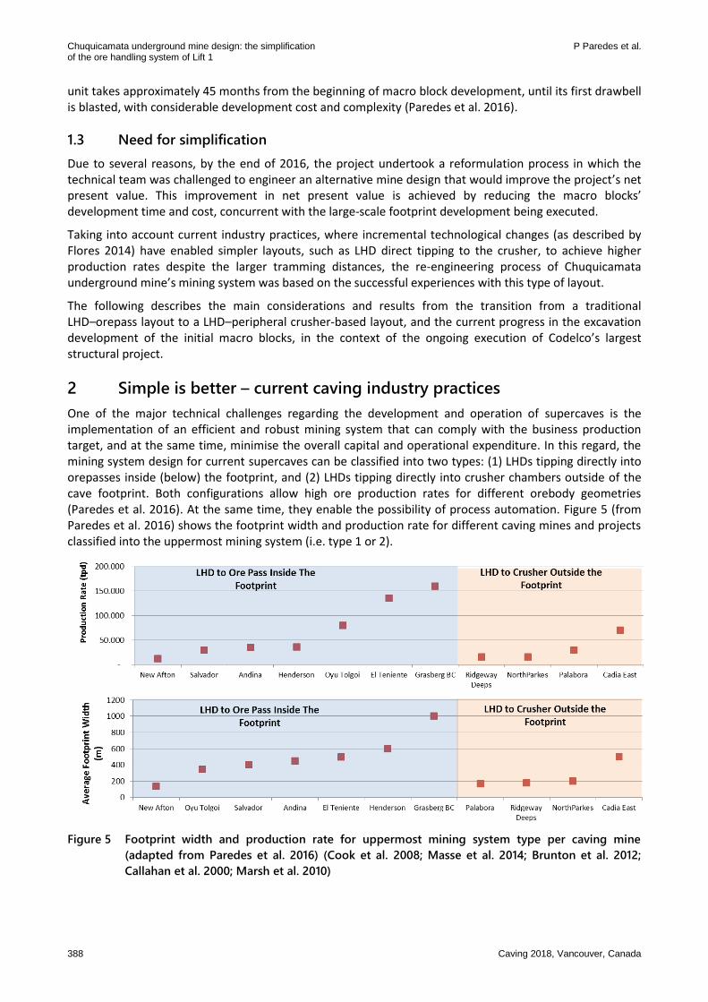
One of the major technical challenges regarding the development and operation of supercaves is the implementation of an efficient and robust mining system that can comply with the business production target, and at the same time, minimise the overall capital and operational expenditure. In this regard, the mining system design for current supercaves can be classified into two types: (1) LHDs tipping directly into orepasses inside (below) the footprint, and (2) LHDs tipping directly into crusher chambers outside of the cave footprint. Both configurations allow high ore production rates for different orebody geometries (Paredes et al. 2016). At the same time, they enable the possibility of process automation. Figure 5 (from Paredes et al. 2016) shows the footprint width and production rate for different caving mines and projects classified into the uppermost mining system (i.e. type 1 or 2).
Figure 5 Footprint width and production rate for uppermost mining system type per caving mine
(adapted from Paredes et al. 2016) (Cook et al. 2008; Masse et al. 2014; Brunton et al. 2012;
Callahan et al. 2000; Marsh et al. 2010)
Mine planning
Caving 2018, Vancouver, Canada 389
Mining systems based on the direct tipping of LHDs into crusher chambers outside the footprint imply a significantly lower excavation density per square metre compared to those based on the tipping of LHDs into orepasses inside the footprint, which makes type 2 attractive from a cost-efficiency perspective.
On the other hand, systems based on LHDs tipping directly into orepasses inside the footprint (type 1) are widely used because they ensure a high production capacity of the mining area under the paradigm that states “the most efficient mining system is the one that minimises the LHD tramming distance” (Chacón et al. 2004). This is the main reason why the original PMCHS design considered that kind of solution (type 1). Nevertheless, during recent years, mining systems based on the direct tipping of LHDs into crushers outside of the footprint (type 2) have been able to adapt to wider orebodies (over 200 m, as in Chuquicamata’s case) and have proven to be highly productive by ‘debottlenecking’ the mining process (Paredes et al. 2016; Flores 2014; Manca 2013) by establishing the concept of the ‘rock factory’.
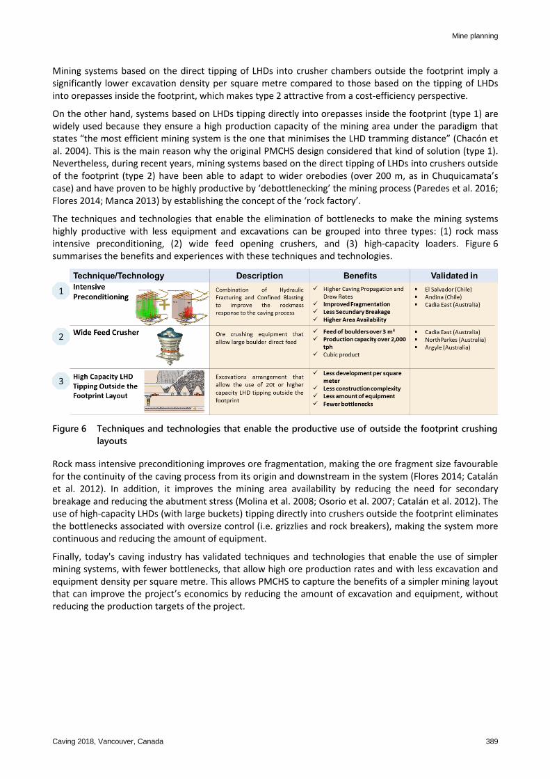
The techniques and technologies that enable the elimination of bottlenecks to make the mining systems highly productive with less equipment and excavations can be grouped into three types: (1) rock mass intensive preconditioning, (2) wide feed opening crushers, and (3) high-capacity loaders. Figure 6 summarises the benefits and experiences with these techniques and technologies.
Figure 6 Techniques and technologies that enable the productive use of outside the footprint crushing
layouts
Rock mass intensive preconditioning improves ore fragmentation, making the ore fragment size favourable for the continuity of the caving process from its origin and downstream in the system (Flores 2014; Catalán et al. 2012). In addition, it improves the mining area availability by reducing the need for secondary breakage and reducing the abutment stress (Molina et al. 2008; Osorio et al. 2007; Catalán et al. 2012). The use of high-capacity LHDs (with large buckets) tipping directly into crushers outside the footprint eliminates the bottlenecks associated with oversize control (i.e. grizzlies and rock breakers), making the system more continuous and reducing the amount of equipment.
Finally, today's caving industry has validated techniques and technologies that enable the use of simpler mining systems, with fewer bottlenecks, that allow high ore production rates and with less excavation and equipment density per square metre. This allows PMCHS to capture the benefits of a simpler mining layout that can improve the project’s economics by reducing the amount of excavation and equipment, without reducing the production targets of the project.
Chuquicamata underground mine design: the simplification P Paredes et al. of the ore handling system of Lift 1
390 Caving 2018, Vancouver, Canada
3 Simplified mine design
3.1 Mining process
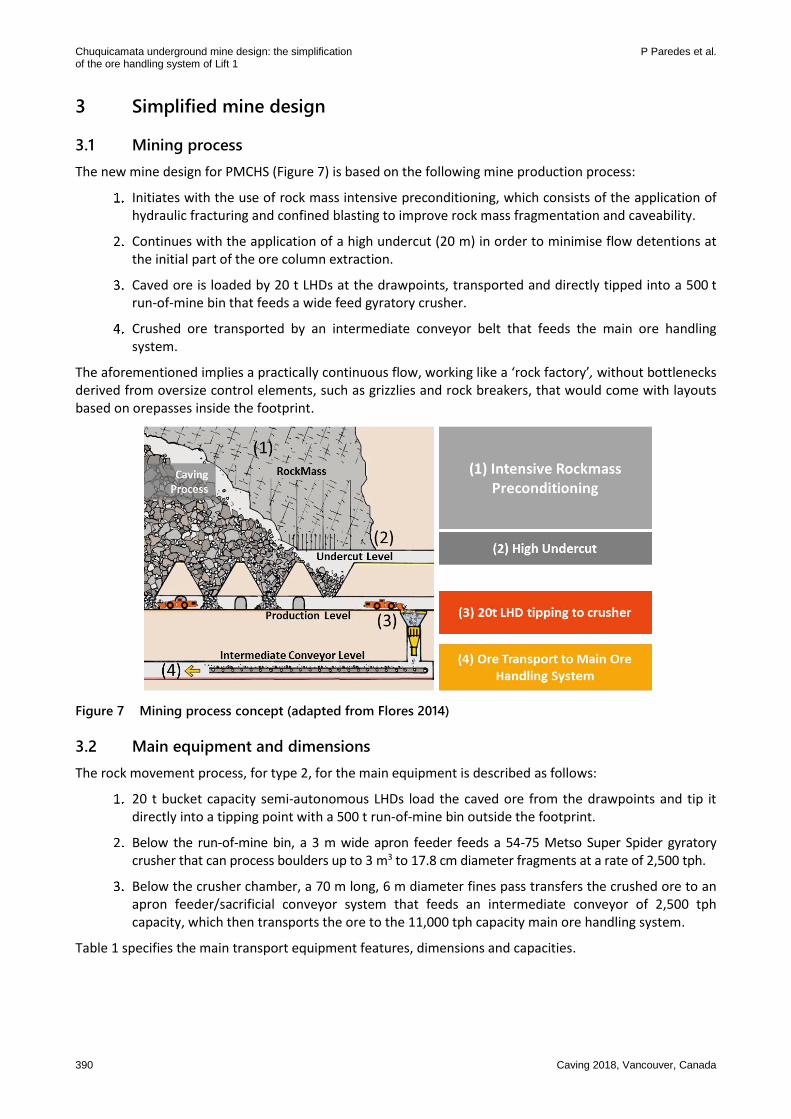
The new mine design for PMCHS (Figure 7) is based on the following mine production process:
Initiates with the use of rock mass intensive preconditioning, which consists of the application of hydraulic fracturing and confined blasting to improve rock mass fragmentation and caveability.
Continues with the application of a high undercut (20 m) in order to minimise flow detentions at the initial part of the ore column extraction.
Caved ore is loaded by 20 t LHDs at the drawpoints, transported and directly tipped into a 500 t run-of-mine bin that feeds a wide feed gyratory crusher.
Crushed ore transported by an intermediate conveyor belt that feeds the main ore handling system.
The aforementioned implies a practically continuous flow, working like a ‘rock factory’, without bottlenecks derived from oversize control elements, such as grizzlies and rock breakers, that would come with layouts based on orepasses inside the footprint.
Figure 7 Mining process concept (adapted from Flores 2014)
3.2 Main equipment and dimensions
The rock movement process, for type 2, for the main equipment is described as follows:
20 t bucket capacity semi-autonomous LHDs load the caved ore from the drawpoints and tip it directly into a tipping point with a 500 t run-of-mine bin outside the footprint.
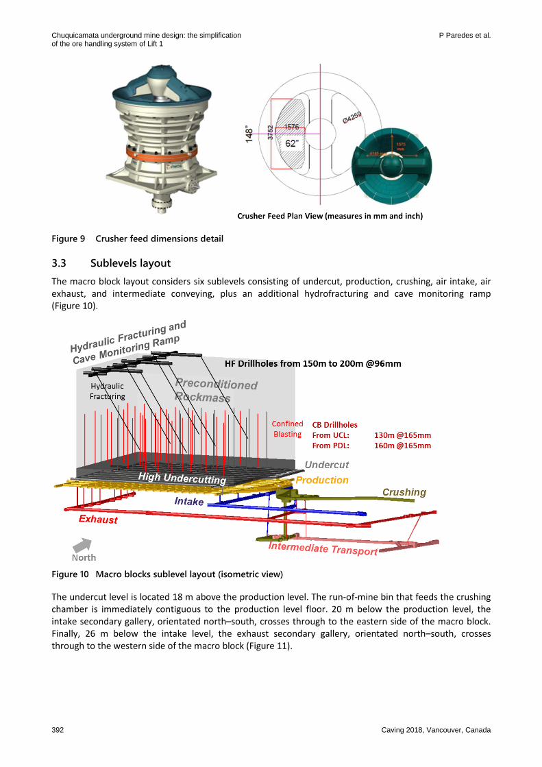
Below the run-of-mine bin, a 3 m wide apron feeder feeds a 54-75 Metso Super Spider gyratory crusher that can process boulders up to 3 m3 to 17.8 cm diameter fragments at a rate of 2,500 tph.
Below the crusher chamber, a 70 m long, 6 m diameter fines pass transfers the crushed ore to an apron feeder/sacrificial conveyor system that feeds an intermediate conveyor of 2,500 tph capacity, which then transports the ore to the 11,000 tph capacity main ore handling system.
Table 1 specifies the main transport equipment features, dimensions and capacities.
Mine planning
Caving 2018, Vancouver, Canada 391
Table 1 Main transport equipment dimensions and capacities
Equipment Dimensions/capacity
Semi-autonomous LHD 13.7 m3 bucket
20 t payload
54-75 MKS gyratory crusher
1.5 m feed dimension
2,500 tph
Apron feeder 3 m width
0.07 m/s speed
Sacrificial conveyor 30–60 m length
72 inch width
2,500 tph
0.25 m/s speed
Intermediate conveyor 290 m length
48 inch width
2,500 tph
4.3 m/s speed
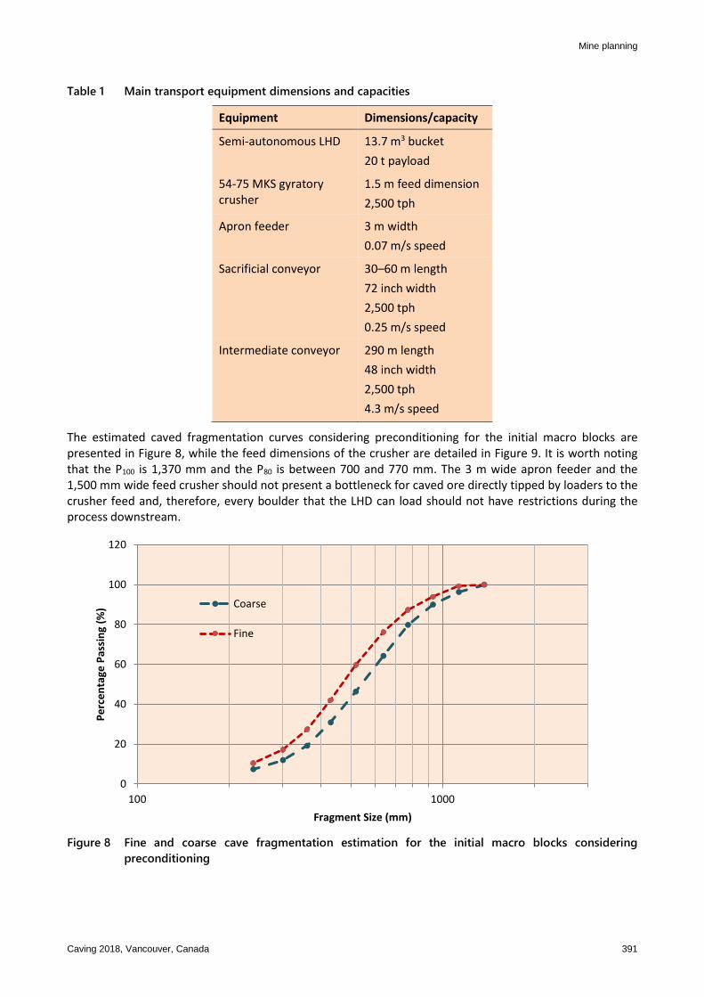
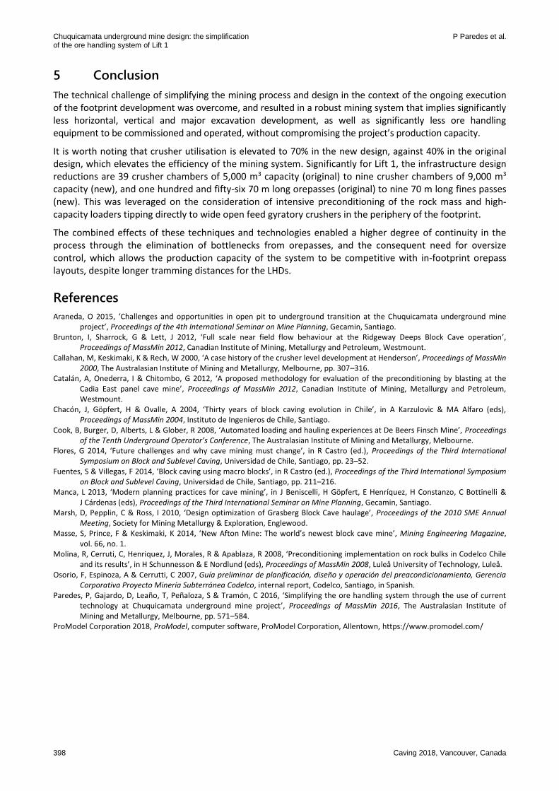
The estimated caved fragmentation curves considering preconditioning for the initial macro blocks are presented in Figure 8, while the feed dimensions of the crusher are detailed in Figure 9. It is worth noting that the P100 is 1,370 mm and the P80 is between 700 and 770 mm. The 3 m wide apron feeder and the 1,500 mm wide feed crusher should not present a bottleneck for caved ore directly tipped by loaders to the crusher feed and, therefore, every boulder that the LHD can load should not have restrictions during the process downstream.
Figure 8 Fine and coarse cave fragmentation estimation for the initial macro blocks considering
preconditioning
0
20
40
60
80
100
120
100 1000
Pe
rce
nta
ge P
assi
ng
(%)
Fragment Size (mm)
Coarse
Fine
Chuquicamata underground mine design: the simplification P Paredes et al. of the ore handling system of Lift 1
392 Caving 2018, Vancouver, Canada
Figure 9 Crusher feed dimensions detail
3.3 Sublevels layout
The macro block layout considers six sublevels consisting of undercut, production, crushing, air intake, air exhaust, and intermediate conveying, plus an additional hydrofracturing and cave monitoring ramp (Figure 10).
Figure 10 Macro blocks sublevel layout (isometric view)
The undercut level is located 18 m above the production level. The run-of-mine bin that feeds the crushing chamber is immediately contiguous to the production level floor. 20 m below the production level, the intake secondary gallery, orientated north–south, crosses through to the eastern side of the macro block. Finally, 26 m below the intake level, the exhaust secondary gallery, orientated north–south, crosses through to the western side of the macro block (Figure 11).
Mine planning
Caving 2018, Vancouver, Canada 393
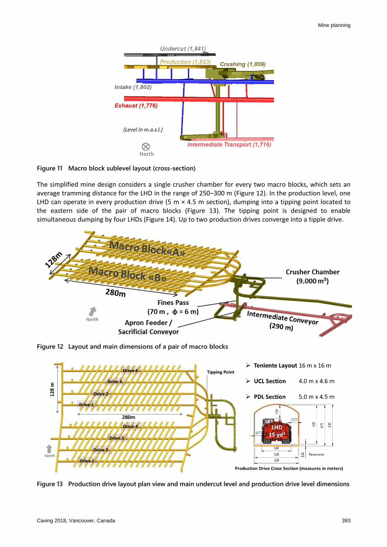
Figure 11 Macro block sublevel layout (cross-section)
The simplified mine design considers a single crusher chamber for every two macro blocks, which sets an average tramming distance for the LHD in the range of 250–300 m (Figure 12). In the production level, one LHD can operate in every production drive (5 m × 4.5 m section), dumping into a tipping point located to the eastern side of the pair of macro blocks (Figure 13). The tipping point is designed to enable simultaneous dumping by four LHDs (Figure 14). Up to two production drives converge into a tipple drive.
Figure 12 Layout and main dimensions of a pair of macro blocks
Figure 13 Production drive layout plan view and main undercut level and production drive level dimensions

Chuquicamata underground mine design: the simplification P Paredes et al. of the ore handling system of Lift 1
394 Caving 2018, Vancouver, Canada
(a) (b)
Figure 14 (a) Tipping point plan view and referential photos; and (b) Isometric view of crusher chamber
equipment layout
3.4 Production capacity
In order to evaluate the production capacity of the mining system for the new design (type 2), a simulation of the whole Lift 1 production was performed using the software ProModel® (ProModel Corporation 2018). The battery limit for the simulation considered the whole mining process from the LHD operation and secondary breakage in the production level, to the underground ore crushing and transport, and the overland conveyors. The simulation results show that the whole mining and ore handling system is able to produce consistently at a rate of 140,000 tpd. In particular, macro blocks in this mining system simulation are able to produce at a rate of 19,300 tpd and, therefore, are able to meet the target maximum production of 19,200 tpd in the production schedule. Figure 15 shows the production schedule requirements for every macro block in Lift 1, and the production capacity per macro block. It is possible to appreciate that the maximum production requirement (19,200 tpd) never overcomes the production capacity (19,300 tpd). In terms of crushing equipment utilisation, this design implies a 70% utilisation of the installed capacity.
Figure 15 Macro blocks’ planned production rates and production capacity
Mine planning
Caving 2018, Vancouver, Canada 395
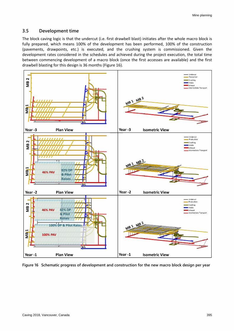
3.5 Development time
The block caving logic is that the undercut (i.e. first drawbell blast) initiates after the whole macro block is fully prepared, which means 100% of the development has been performed, 100% of the construction (pavements, drawpoints, etc.) is executed, and the crushing system is commissioned. Given the development rates considered in the schedules and achieved during the project execution, the total time between commencing development of a macro block (once the first accesses are available) and the first drawbell blasting for this design is 36 months (Figure 16).
Figure 16 Schematic progress of development and construction for the new macro block design per year
Chuquicamata underground mine design: the simplification P Paredes et al. of the ore handling system of Lift 1
396 Caving 2018, Vancouver, Canada
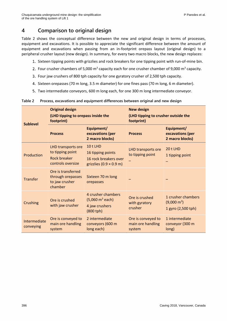
4 Comparison to original design
Table 2 shows the conceptual difference between the new and original design in terms of processes, equipment and excavations. It is possible to appreciate the significant difference between the amount of equipment and excavations when passing from an in-footprint orepass layout (original design) to a peripheral crusher layout (new design). In summary, for every two macro blocks, the new design replaces:
Sixteen tipping points with grizzlies and rock breakers for one tipping point with run-of-mine bin.
Four crusher chambers of 5,000 m3 capacity each for one crusher chamber of 9,000 m3 capacity.
Four jaw crushers of 800 tph capacity for one gyratory crusher of 2,500 tph capacity.
Sixteen orepasses (70 m long, 3.5 m diameter) for one fines pass (70 m long, 6 m diameter).
Two intermediate conveyors, 600 m long each, for one 300 m long intermediate conveyor.
Table 2 Process, excavations and equipment differences between original and new design
Sublevel
Original design
(LHD tipping to orepass inside the footprint)
New design
(LHD tipping to crusher outside the footprint)
Process Equipment/ excavations (per 2 macro blocks)
Process Equipment/ excavations (per 2 macro blocks)
Production
LHD transports ore to tipping point
Rock breaker controls oversize
10 t LHD
16 tipping points
16 rock breakers over grizzlies (0.9 × 0.9 m)
LHD transports ore to tipping point
–
20 t LHD
1 tipping point
–
Transfer
Ore is transferred through orepasses to jaw crusher chamber
Sixteen 70 m long orepasses
– –
Crushing Ore is crushed with jaw crusher
4 crusher chambers (5,060 m3 each)
4 jaw crushers (800 tph)
Ore is crushed with gyratory crusher
1 crusher chambers (9,000 m3)
1 gyro (2,500 tph)
Intermediate conveying
Ore is conveyed to main ore handling system
2 intermediate conveyors (600 m long each)
Ore is conveyed to main ore handling system
1 intermediate conveyor (300 m long)
Mine planning
Caving 2018, Vancouver, Canada 397
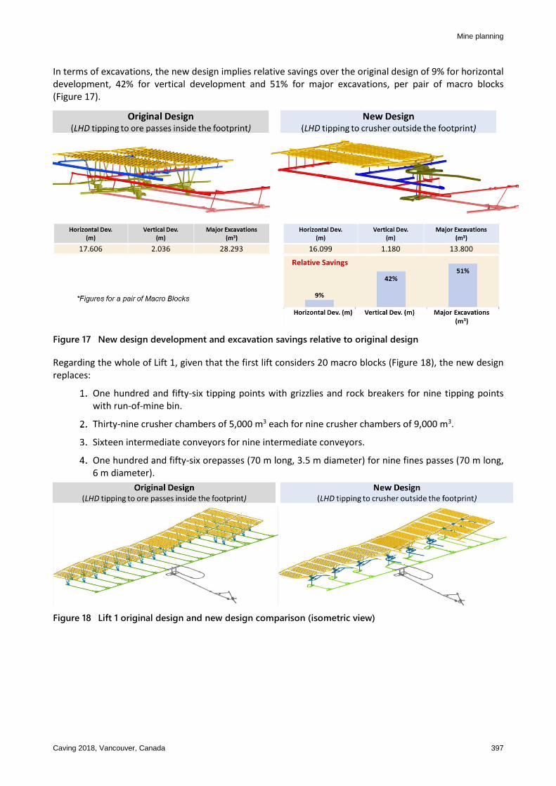
In terms of excavations, the new design implies relative savings over the original design of 9% for horizontal development, 42% for vertical development and 51% for major excavations, per pair of macro blocks (Figure 17).
Figure 17 New design development and excavation savings relative to original design
Regarding the whole of Lift 1, given that the first lift considers 20 macro blocks (Figure 18), the new design replaces:
One hundred and fifty-six tipping points with grizzlies and rock breakers for nine tipping points with run-of-mine bin.
Thirty-nine crusher chambers of 5,000 m3 each for nine crusher chambers of 9,000 m3.
Sixteen intermediate conveyors for nine intermediate conveyors.
One hundred and fifty-six orepasses (70 m long, 3.5 m diameter) for nine fines passes (70 m long, 6 m diameter).
Figure 18 Lift 1 original design and new design comparison (isometric view)
Chuquicamata underground mine design: the simplification P Paredes et al. of the ore handling system of Lift 1
398 Caving 2018, Vancouver, Canada
5 Conclusion
The technical challenge of simplifying the mining process and design in the context of the ongoing execution of the footprint development was overcome, and resulted in a robust mining system that implies significantly less horizontal, vertical and major excavation development, as well as significantly less ore handling equipment to be commissioned and operated, without compromising the project’s production capacity.
It is worth noting that crusher utilisation is elevated to 70% in the new design, against 40% in the original design, which elevates the efficiency of the mining system. Significantly for Lift 1, the infrastructure design reductions are 39 crusher chambers of 5,000 m3 capacity (original) to nine crusher chambers of 9,000 m3 capacity (new), and one hundred and fifty-six 70 m long orepasses (original) to nine 70 m long fines passes (new). This was leveraged on the consideration of intensive preconditioning of the rock mass and high-capacity loaders tipping directly to wide open feed gyratory crushers in the periphery of the footprint.
The combined effects of these techniques and technologies enabled a higher degree of continuity in the process through the elimination of bottlenecks from orepasses, and the consequent need for oversize control, which allows the production capacity of the system to be competitive with in-footprint orepass layouts, despite longer tramming distances for the LHDs.
References
Araneda, O 2015, ‘Challenges and opportunities in open pit to underground transition at the Chuquicamata underground mine project’, Proceedings of the 4th International Seminar on Mine Planning, Gecamin, Santiago.
Brunton, I, Sharrock, G & Lett, J 2012, ‘Full scale near field flow behaviour at the Ridgeway Deeps Block Cave operation’, Proceedings of MassMin 2012, Canadian Institute of Mining, Metallurgy and Petroleum, Westmount.
Callahan, M, Keskimaki, K & Rech, W 2000, ‘A case history of the crusher level development at Henderson’, Proceedings of MassMin 2000, The Australasian Institute of Mining and Metallurgy, Melbourne, pp. 307–316.
Catalán, A, Onederra, I & Chitombo, G 2012, ‘A proposed methodology for evaluation of the preconditioning by blasting at the Cadia East panel cave mine’, Proceedings of MassMin 2012, Canadian Institute of Mining, Metallurgy and Petroleum, Westmount.
Chacón, J, Göpfert, H & Ovalle, A 2004, ‘Thirty years of block caving evolution in Chile’, in A Karzulovic & MA Alfaro (eds), Proceedings of MassMin 2004, Instituto de Ingenieros de Chile, Santiago.
Cook, B, Burger, D, Alberts, L & Glober, R 2008, ‘Automated loading and hauling experiences at De Beers Finsch Mine’, Proceedings of the Tenth Underground Operator’s Conference, The Australasian Institute of Mining and Metallurgy, Melbourne.
Flores, G 2014, ‘Future challenges and why cave mining must change’, in R Castro (ed.), Proceedings of the Third International Symposium on Block and Sublevel Caving, Universidad de Chile, Santiago, pp. 23–52.
Fuentes, S & Villegas, F 2014, ‘Block caving using macro blocks’, in R Castro (ed.), Proceedings of the Third International Symposium on Block and Sublevel Caving, Universidad de Chile, Santiago, pp. 211–216.
Manca, L 2013, ‘Modern planning practices for cave mining’, in J Beniscelli, H Göpfert, E Henríquez, H Constanzo, C Bottinelli & J Cárdenas (eds), Proceedings of the Third International Seminar on Mine Planning, Gecamin, Santiago.
Marsh, D, Pepplin, C & Ross, I 2010, ‘Design optimization of Grasberg Block Cave haulage’, Proceedings of the 2010 SME Annual Meeting, Society for Mining Metallurgy & Exploration, Englewood.
Masse, S, Prince, F & Keskimaki, K 2014, ‘New Afton Mine: The world’s newest block cave mine’, Mining Engineering Magazine, vol. 66, no. 1.
Molina, R, Cerruti, C, Henriquez, J, Morales, R & Apablaza, R 2008, ‘Preconditioning implementation on rock bulks in Codelco Chile and its results’, in H Schunnesson & E Nordlund (eds), Proceedings of MassMin 2008, Luleå University of Technology, Luleå.
Osorio, F, Espinoza, A & Cerrutti, C 2007, Guía preliminar de planificación, diseño y operación del preacondicionamiento, Gerencia Corporativa Proyecto Minería Subterránea Codelco, internal report, Codelco, Santiago, in Spanish.
Paredes, P, Gajardo, D, Leaño, T, Peñaloza, S & Tramón, C 2016, ‘Simplifying the ore handling system through the use of current technology at Chuquicamata underground mine project’, Proceedings of MassMin 2016, The Australasian Institute of Mining and Metallurgy, Melbourne, pp. 571–584.
ProModel Corporation 2018, ProModel, computer software, ProModel Corporation, Allentown, https://www.promodel.com/


![Article Chuquicamata Underground [Hormazabal Et Al 2009]](https://img.pdfslide.net/doc/110x75/55cf8c855503462b138d3e5c/article-chuquicamata-underground-hormazabal-et-al-2009.jpg)

