Embed Size (px)
Citation preview
1/54
Circulation pump, safety valve,
expansion vessel
pressure loss
efficiency of pump
secured heat output
safety valve sizing
expansion vessel sizing
2/54
Circulation pump
similar principle as for heating system
flowrate
according to collector area (specific flowrate l/h.m2)
regime (high-flow, low-flow, according to collector producer)
calculation of pressure loss of collector loop
influence of heat transfer fluid properties (viscosity, density)
low consumption of electricity for pump in operation
working point in the area of high efficiency of pump
circulators with permanent magnets
3/54
Pressure loss calculation
friction loss
local loss (valves, fittings, etc.)
loss of components (collector field, heat exchanger)
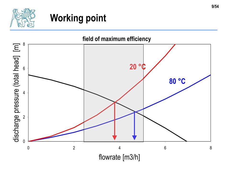
determination of reference working point P
flowrate of fluid (according to collector area)
pressure loss for considered temperature (20 °C, 80 °C)
selection of pump
4/54
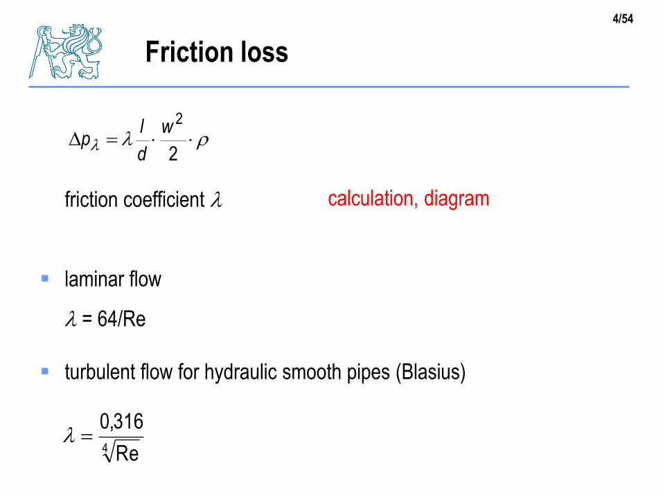
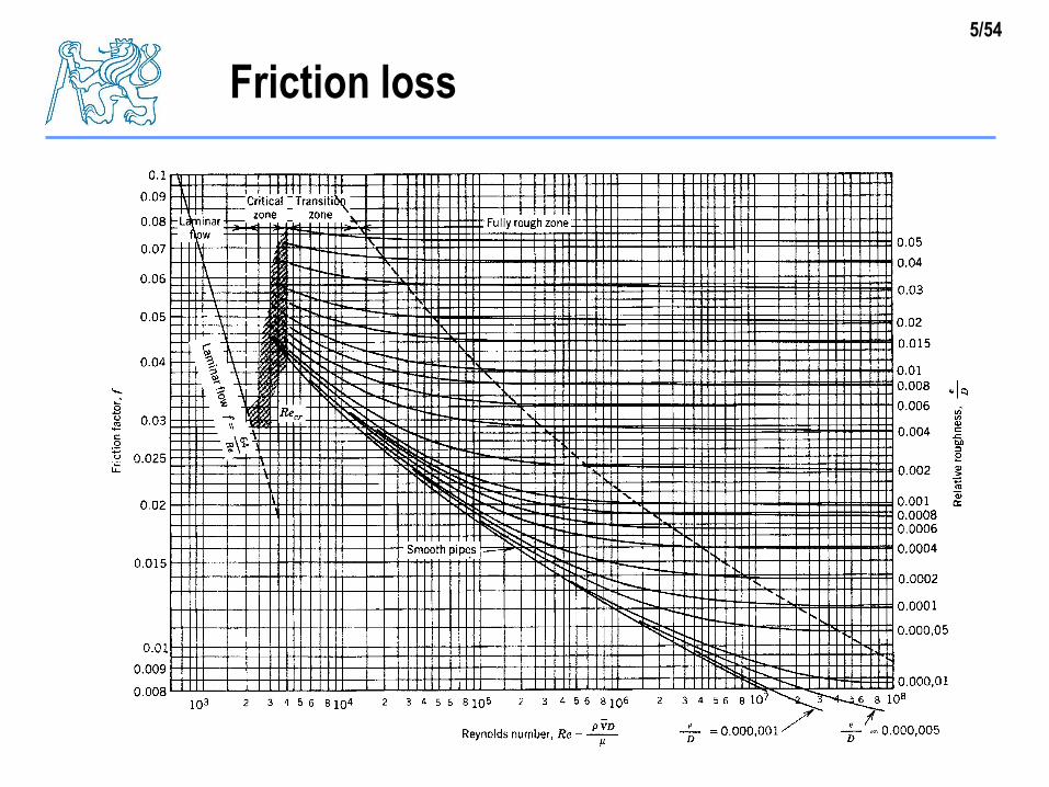
friction coefficient l
laminar flow
l = 64/Re
turbulent flow for hydraulic smooth pipes (Blasius)
Friction loss
ll 2
2w
d
lp
calculation, diagram
4 Re
316,0l
5/54
Friction loss
6/54
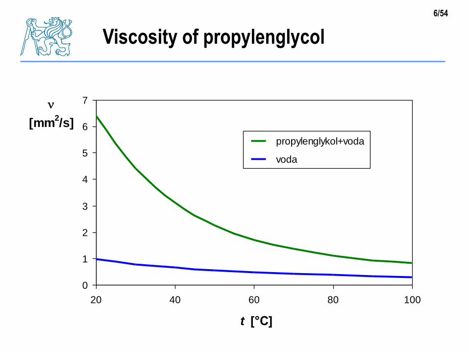
Viscosity of propylenglycol
0
1
2
3
4
5
6
7
20 40 60 80 100
t [°C]
[mm2/s]
propylenglykol+voda
voda
7/54
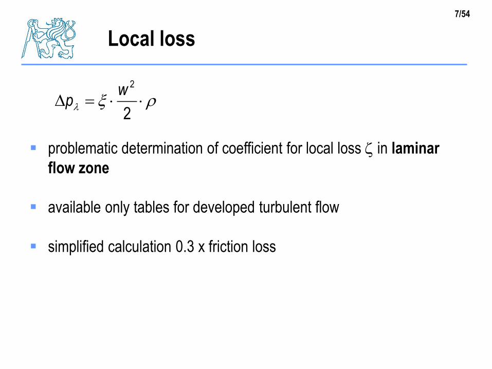
problematic determination of coefficient for local loss in laminar
flow zone
available only tables for developed turbulent flow
simplified calculation 0.3 x friction loss
Local loss
l 2
2wp
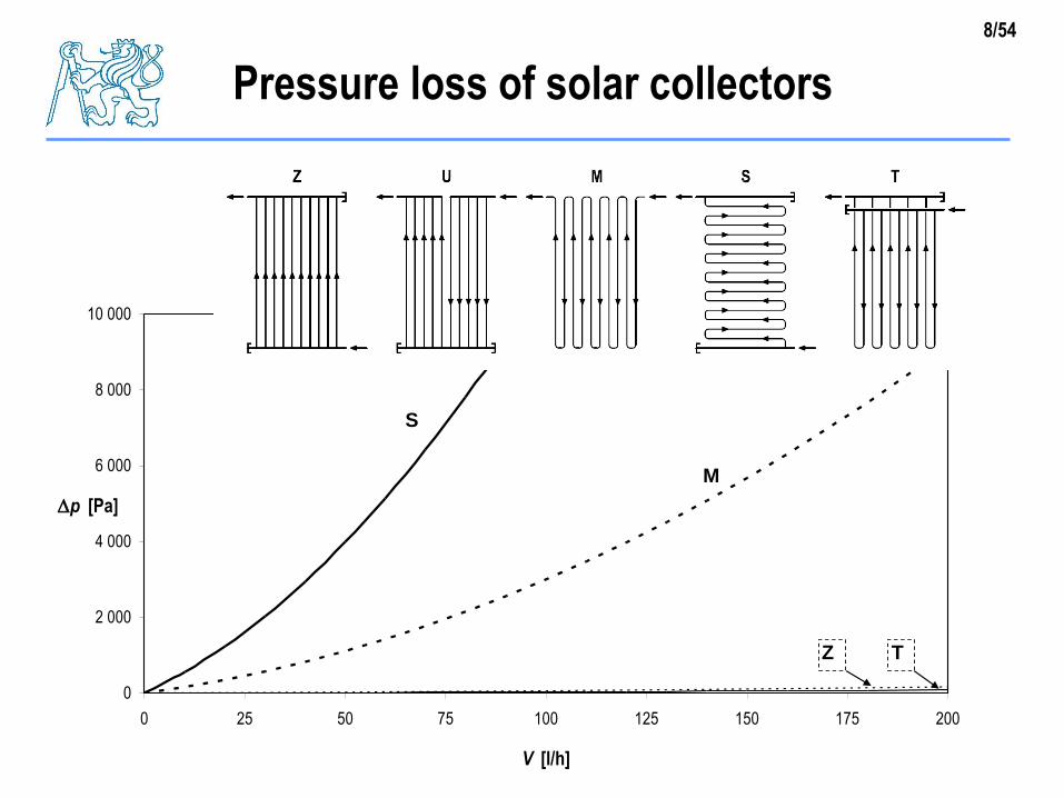
8/54
0
2 000
4 000
6 000
8 000
10 000
0 25 50 75 100 125 150 175 200
V [l/h]
p [Pa]
S
M
Z T
Pressure loss of solar collectors
9/54
Working point
0
2
4
6
8
0 2 4 6 8
průtok [m3/h]
dis
po
zičn
í tla
k [m
]
20 °C
80 °C
field of maximum efficiency
flowrate [m3/h]
disc
harg
e pr
essu
re (
tota
l hea
d]
[m]
10/54
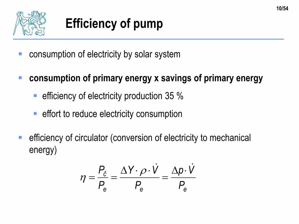
Efficiency of pump
consumption of electricity by solar system
consumption of primary energy x savings of primary energy
efficiency of electricity production 35 %
effort to reduce electricity consumption
efficiency of circulator (conversion of electricity to mechanical
energy)
eee
č
P
Vp
P
VY
P
P
11/54
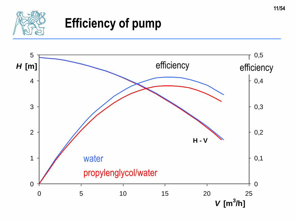
Efficiency of pump
0
1
2
3
4
5
0 5 10 15 20 25
V [m3/h]
H [m]
0
0,1
0,2
0,3
0,4
0,5
účinnost
H - V
účinnost efficiencyefficiency
water
propylenglycol/water
12/54
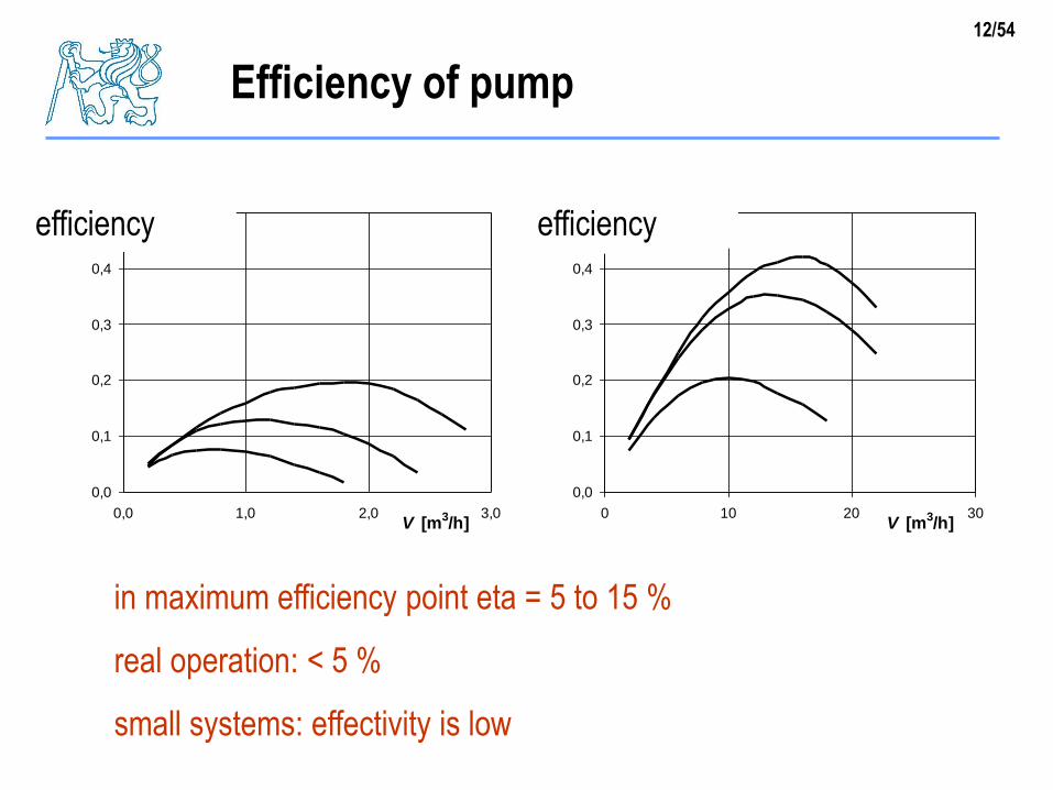
Efficiency of pump
0,0
0,1
0,2
0,3
0,4
0,5
0,0 1,0 2,0 3,0V [m
3/h]
účinnost
0,0
0,1
0,2
0,3
0,4
0,5
0 10 20 30V [m
3/h]
účinnost
in maximum efficiency point eta = 5 to 15 %
real operation: < 5 %
small systems: effectivity is low
efficiencyefficiency
13/54
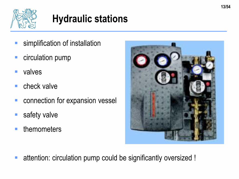
Hydraulic stations
simplification of installation
circulation pump
valves
check valve
connection for expansion vessel
safety valve
themometers
attention: circulation pump could be significantly oversized !
14/54
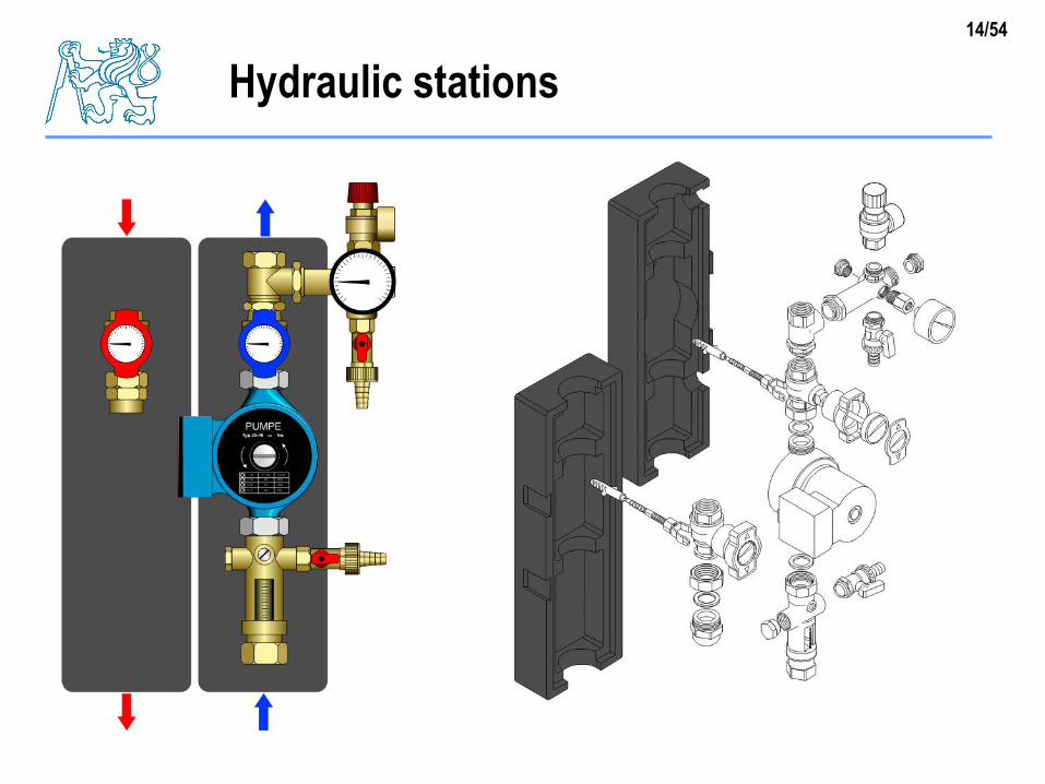
Hydraulic stations
15/54
Electricity consumption
annual electricity need
volume flowrate
pressure loss of collector loop
hydraulic power
efficiency of circulation pump
power input of pump
typical annual operation period 2000 h
calculation for typical operation point tm = 40 °C
16/54
Pressure loss calculation
low flow
velocity w = 0.4 m/s
Reynolds number Re = 3183
friction coefficient l = 0.02 (laminar flow) 0.042 (turbulent)
friction loss pl = 17 000 Pa
local loss pm = 0.3 * pl = 5 600 Pa
pressure loss of heat exchanger 3000 Pa (450 l/h)
pressure loss of collectors 2000 Pa (balance valves)
total: 27 600 Pa
17/54
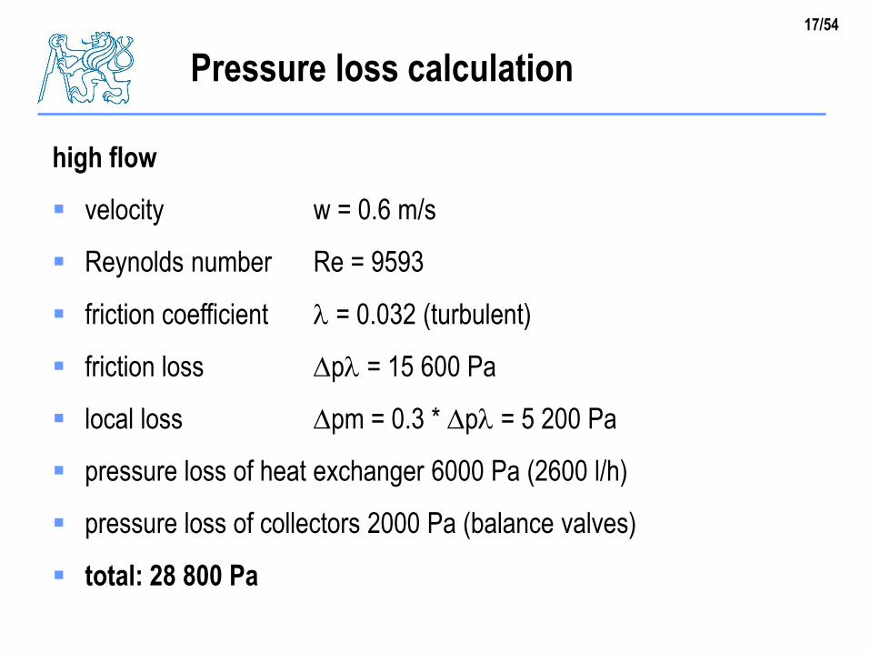
Pressure loss calculation
high flow
velocity w = 0.6 m/s
Reynolds number Re = 9593
friction coefficient l = 0.032 (turbulent)
friction loss pl = 15 600 Pa
local loss pm = 0.3 * pl = 5 200 Pa
pressure loss of heat exchanger 6000 Pa (2600 l/h)
pressure loss of collectors 2000 Pa (balance valves)
total: 28 800 Pa
18/54
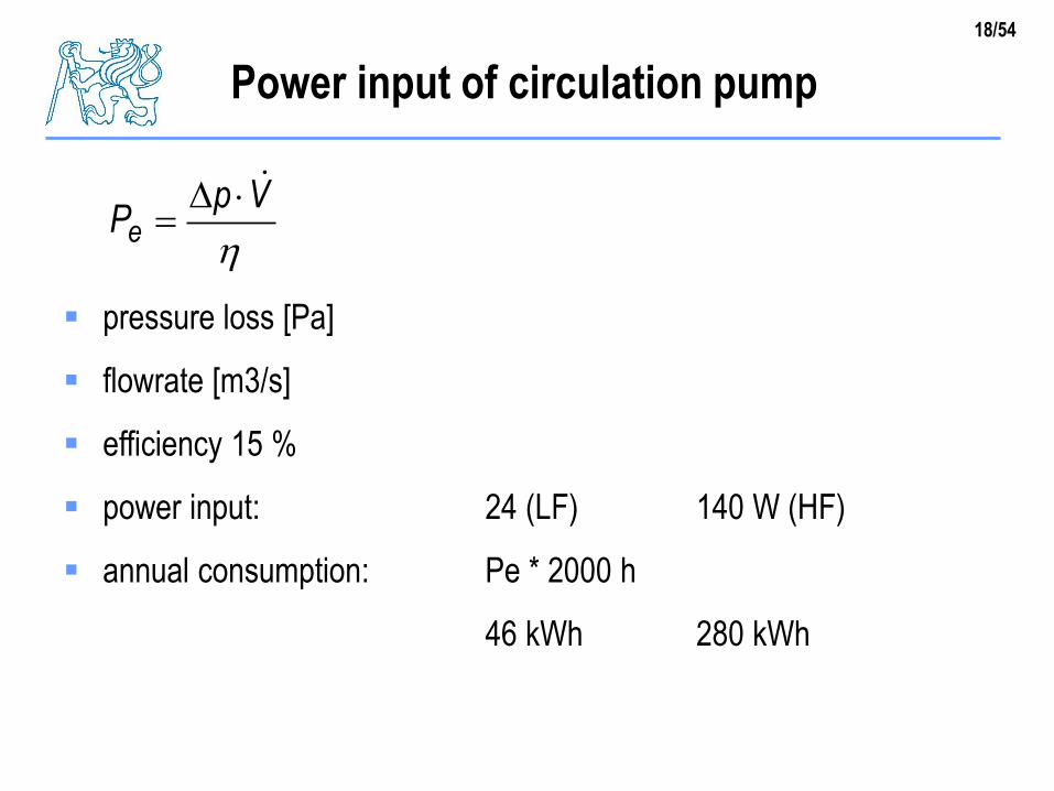
Power input of circulation pump
pressure loss [Pa]
flowrate [m3/s]
efficiency 15 %
power input: 24 (LF) 140 W (HF)
annual consumption: Pe * 2000 h
46 kWh 280 kWh
VpPe
19/54
Safety and protection devices
pressures in system
safety valve
expansion vessel
20/54
Safety and protection devices
safety valve
protects the collector loop against non-permissible pressure
expansion vessel
allows changes of fluid volume (due to thermal expansion)
without extreme increase of pressure above non-perimissible
limit (safety valve will not react during standard operation)
21/54
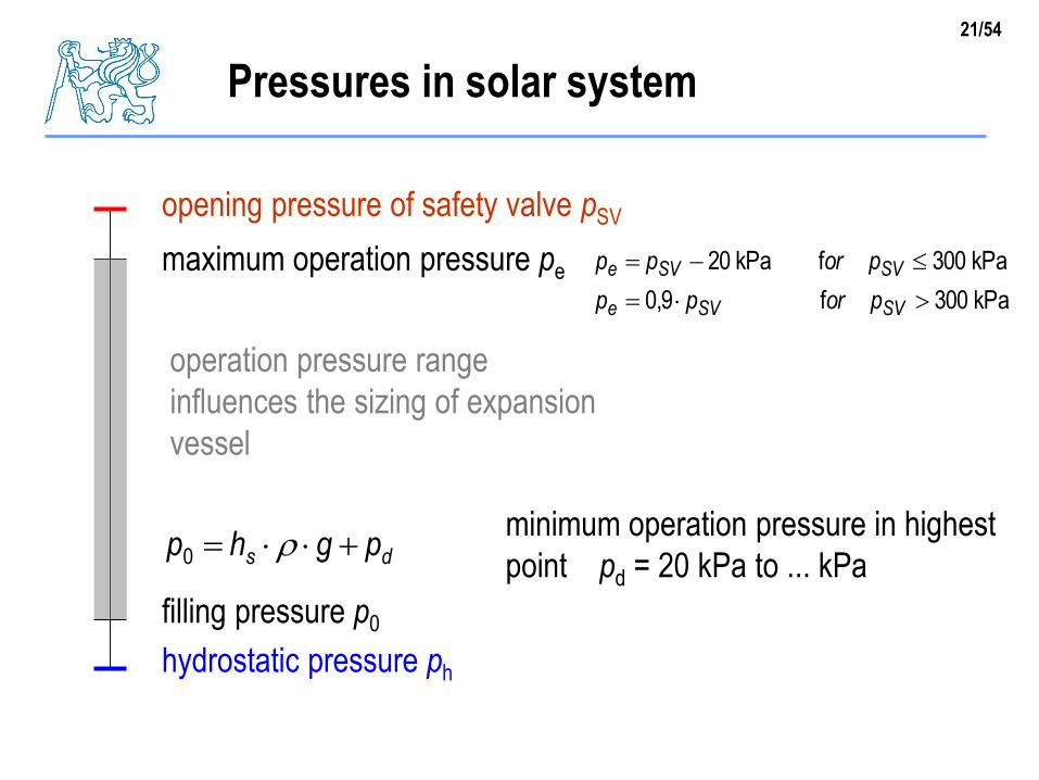
Pressures in solar system
opening pressure of safety valve pSV
maximum operation pressure pe
kPa300f9,0
kPa300fkPa20
SVSVe
SVSVe
porpp
porpp
hydrostatic pressure ph
filling pressure p0
ds pghp 0
minimum operation pressure in highest
point pd = 20 kPa to ... kPa
operation pressure range
influences the sizing of expansion
vessel
22/54
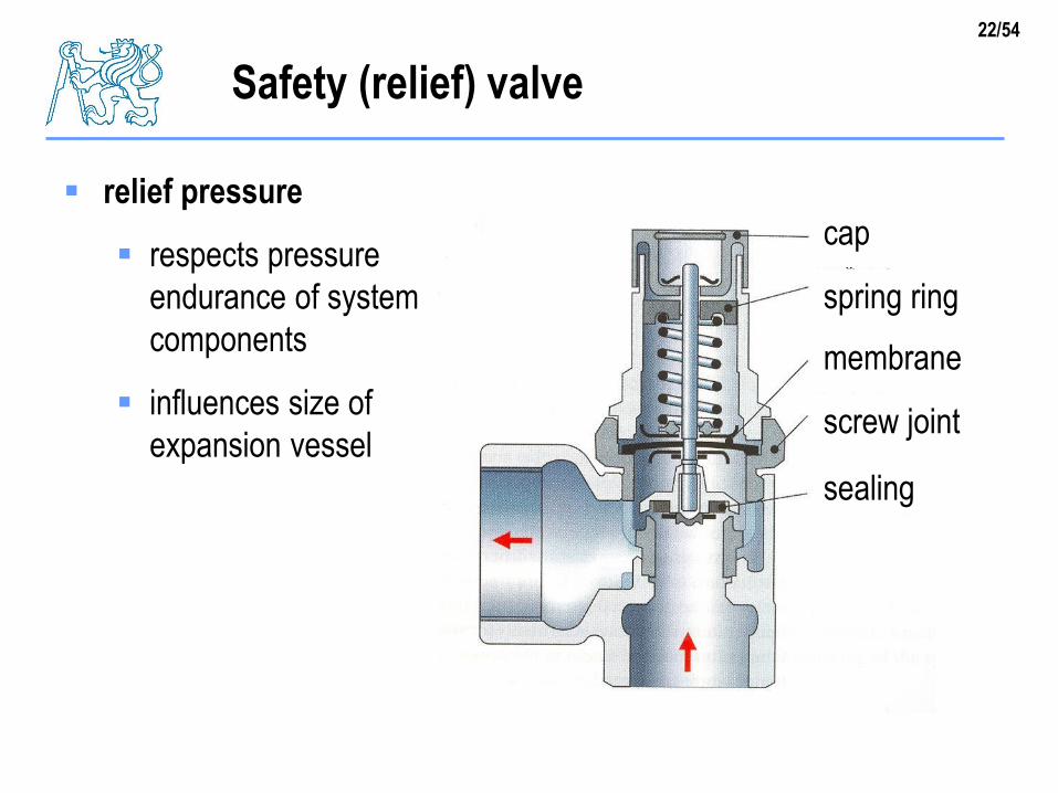
Safety (relief) valve
relief pressure
respects pressure
endurance of system
components
influences size of
expansion vessel
cap
spring ring
membrane
screw joint
sealing
23/54
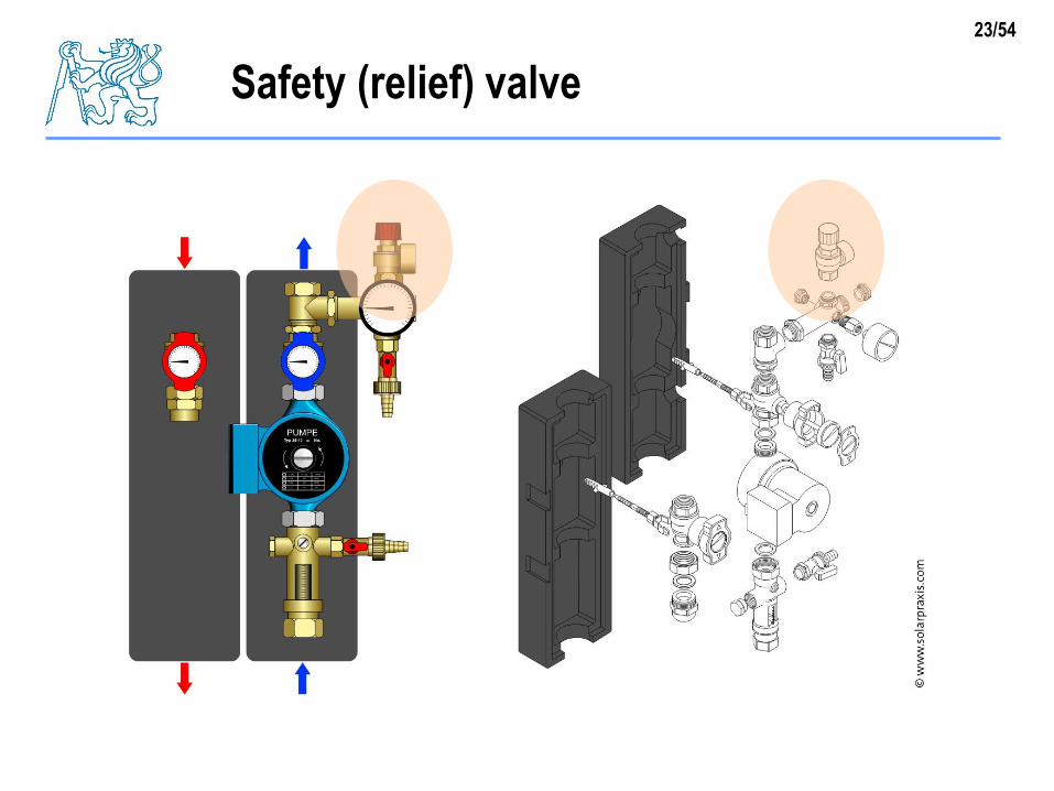
Safety (relief) valve
24/54
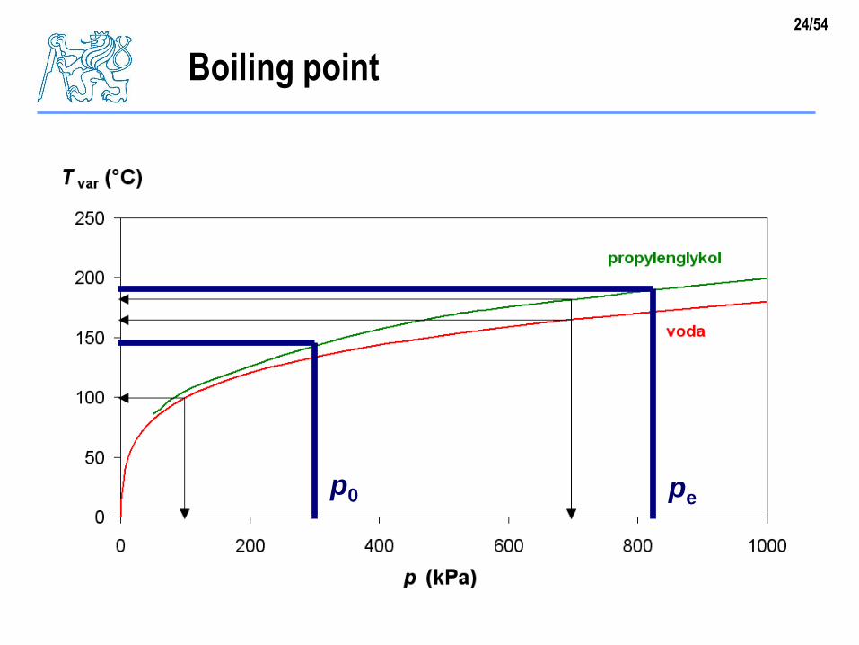
Boiling point
p0 pe
25/54
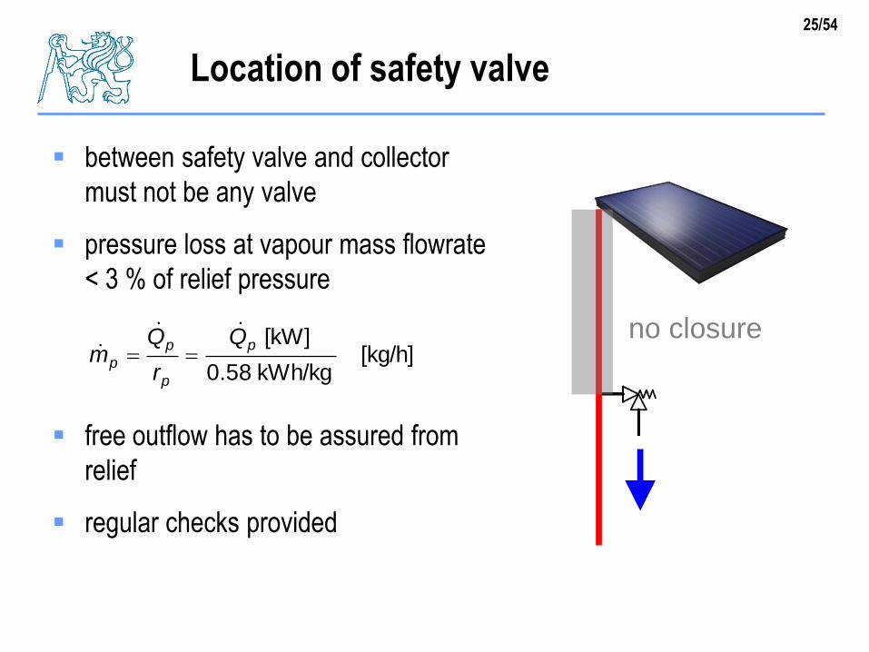
Location of safety valve
between safety valve and collector
must not be any valve
pressure loss at vapour mass flowrate
< 3 % of relief pressure
free outflow has to be assured from
relief
regular checks provided
no closurekg/h][
kWh/kg58.0
[kW]p
p
p
p
Q
r
Qm
26/54
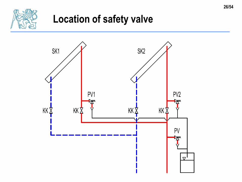
Location of safety valve
27/54
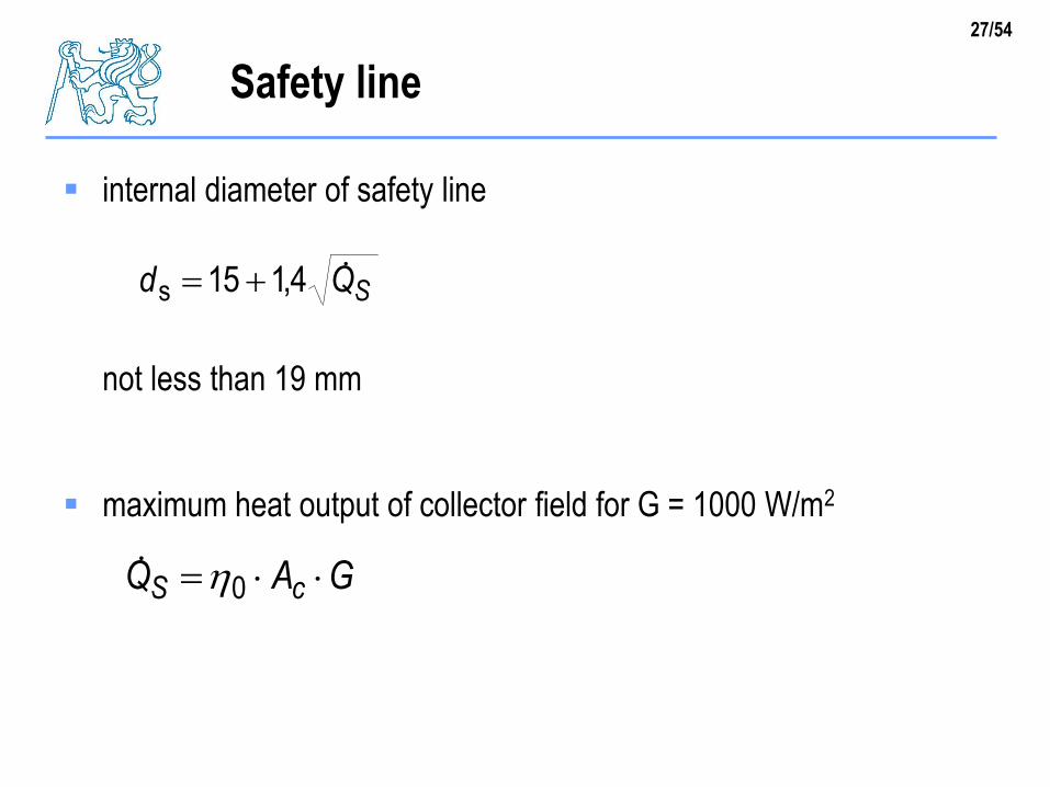
Safety line
internal diameter of safety line
not less than 19 mm
maximum heat output of collector field for G = 1000 W/m2
SQd 4,115s
GAQ cS 0
28/54
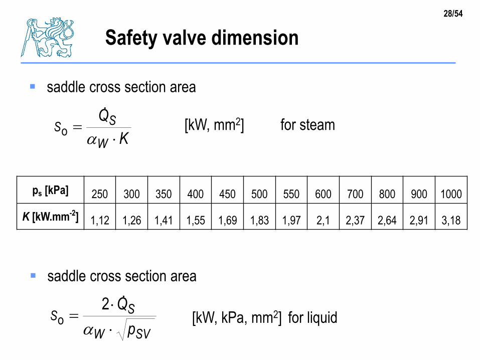
Safety valve dimension
saddle cross section area
ps [kPa] 250 300 350 400 450 500 550 600 700 800 900 1000
K [kW.mm-2] 1,12 1,26 1,41 1,55 1,69 1,83 1,97 2,1 2,37 2,64 2,91 3,18
K
Q
W
SS
o [kW, mm2] for steam
saddle cross section area
SVW
SS
p
Q
2o [kW, kPa, mm2] for liquid
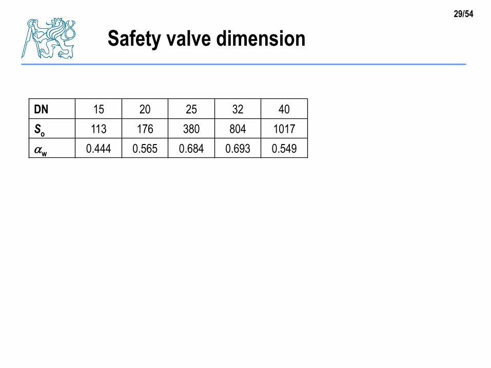
29/54
Safety valve dimension
DN 15 20 25 32 40
So 113 176 380 804 1017
w 0.444 0.565 0.684 0.693 0.549
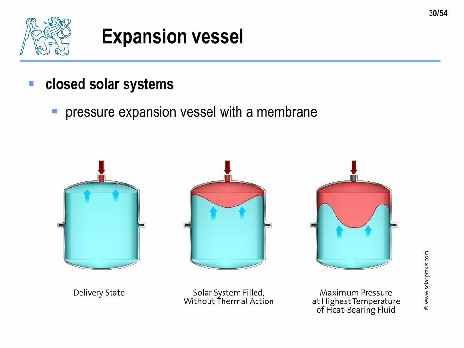
30/54
Expansion vessel
closed solar systems
pressure expansion vessel with a membrane
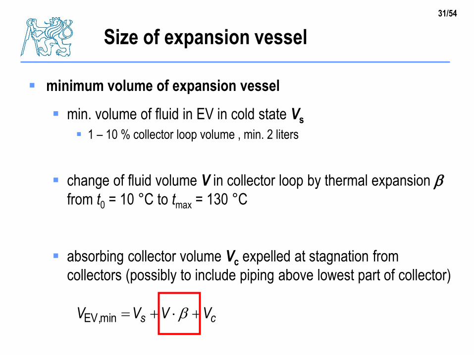
31/54
Size of expansion vessel
minimum volume of expansion vessel
min. volume of fluid in EV in cold state Vs
1 – 10 % collector loop volume , min. 2 liters
change of fluid volume V in collector loop by thermal expansion bfrom t0 = 10 °C to tmax = 130 °C
absorbing collector volume Vc expelled at stagnation from
collectors (possibly to include piping above lowest part of collector)
cs VVVV bminEV,
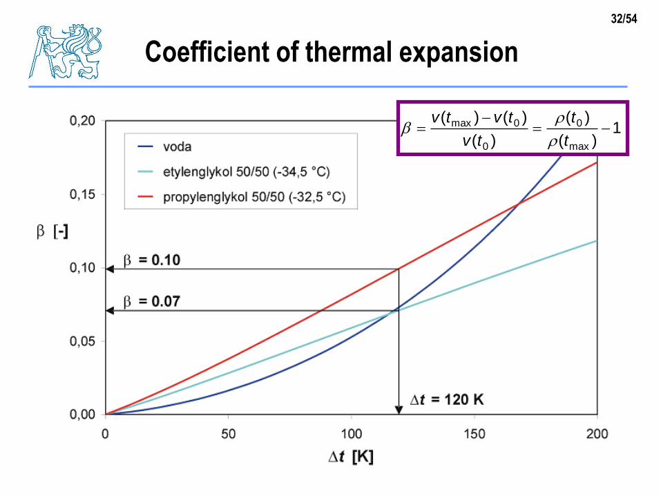
32/54
Coefficient of thermal expansion
1)(
)(
)(
)()(
max
0
0
0max
t
t
tv
tvtv
b
33/54
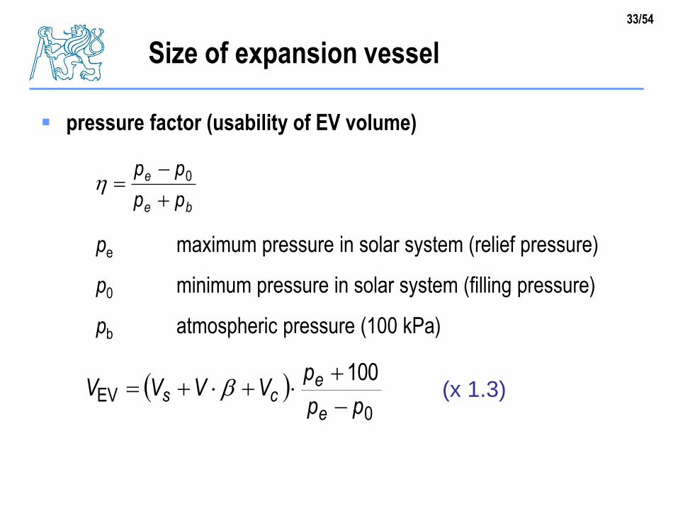
Size of expansion vessel
pressure factor (usability of EV volume)
pe maximum pressure in solar system (relief pressure)
p0 minimum pressure in solar system (filling pressure)
pb atmospheric pressure (100 kPa)
be
e
pp
pp
0
0
EV100
pp
pVVVV
e
ecs
b (x 1.3)
34/54
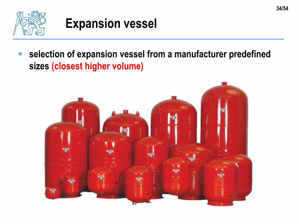
Expansion vessel
selection of expansion vessel from a manufacturer predefined
sizes (closest higher volume)
35/54
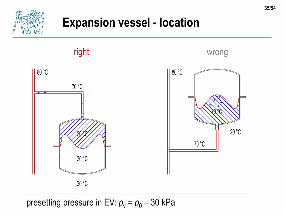
Expansion vessel - location
right wrong
presetting pressure in EV: pv = p0 – 30 kPa
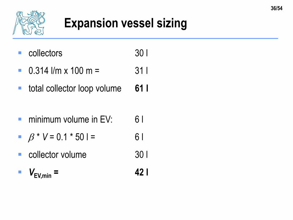
36/54
collectors 30 l
0.314 l/m x 100 m = 31 l
total collector loop volume 61 l
minimum volume in EV: 6 l
b * V = 0.1 * 50 l = 6 l
collector volume 30 l
VEV,min = 42 l
Expansion vessel sizing
37/54
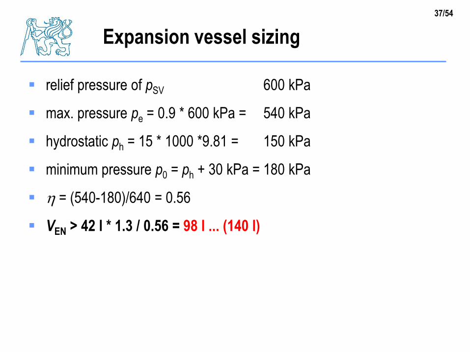
relief pressure of pSV 600 kPa
max. pressure pe = 0.9 * 600 kPa = 540 kPa
hydrostatic ph = 15 * 1000 *9.81 = 150 kPa
minimum pressure p0 = ph + 30 kPa = 180 kPa
= (540-180)/640 = 0.56
VEN > 42 l * 1.3 / 0.56 = 98 l ... (140 l)
Expansion vessel sizing
38/54
Heat exchangers
power
temperature difference
efficiency
39/54
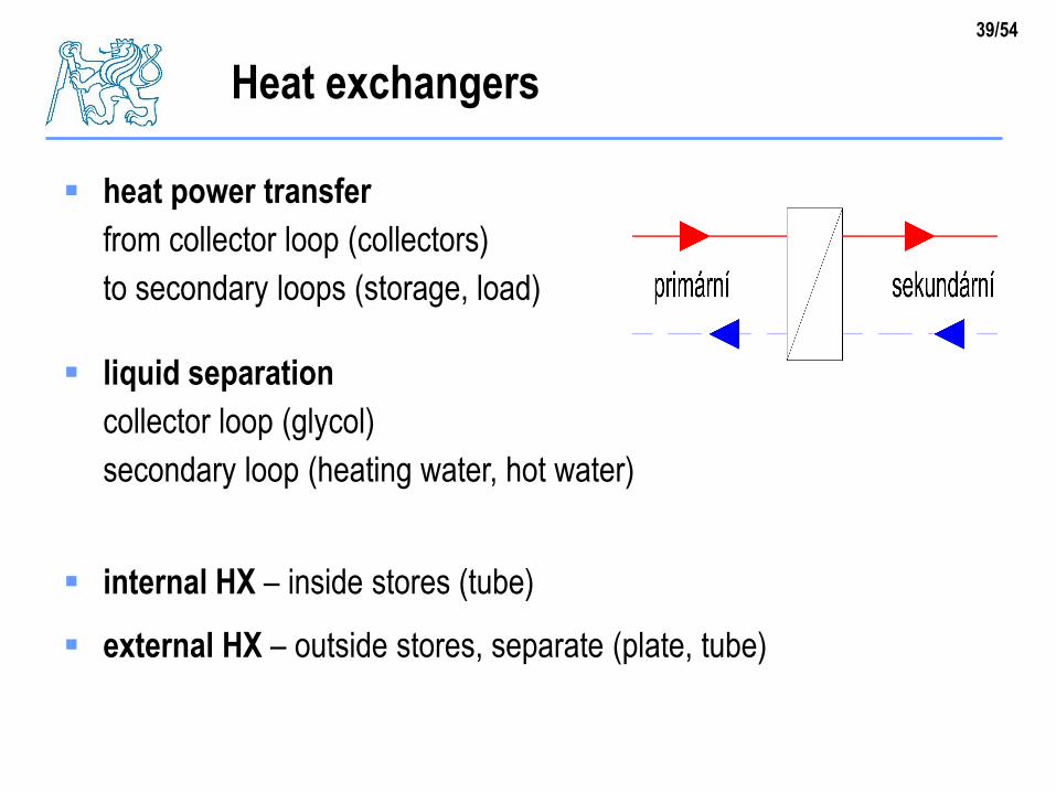
heat power transfer
from collector loop (collectors)
to secondary loops (storage, load)
liquid separation
collector loop (glycol)
secondary loop (heating water, hot water)
internal HX – inside stores (tube)
external HX – outside stores, separate (plate, tube)
Heat exchangers
40/54
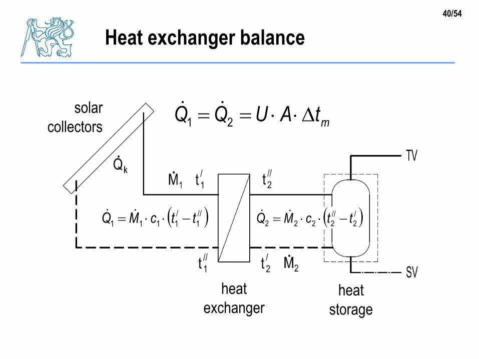
Heat exchanger balance
//
1
/
1111 ttcMQ /
2
//
2222 ttcMQ
mtAUQQ 21solar
collectors
heat
exchangerheat
storage
41/54
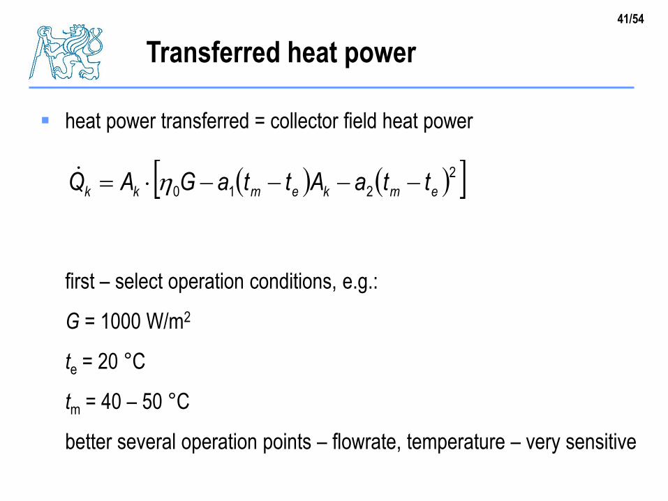
heat power transferred = collector field heat power
first – select operation conditions, e.g.:
G = 1000 W/m2
te = 20 °C
tm = 40 – 50 °C
better several operation points – flowrate, temperature – very sensitive
Transferred heat power
2
210 emkemkk ttaAttaGAQ
42/54
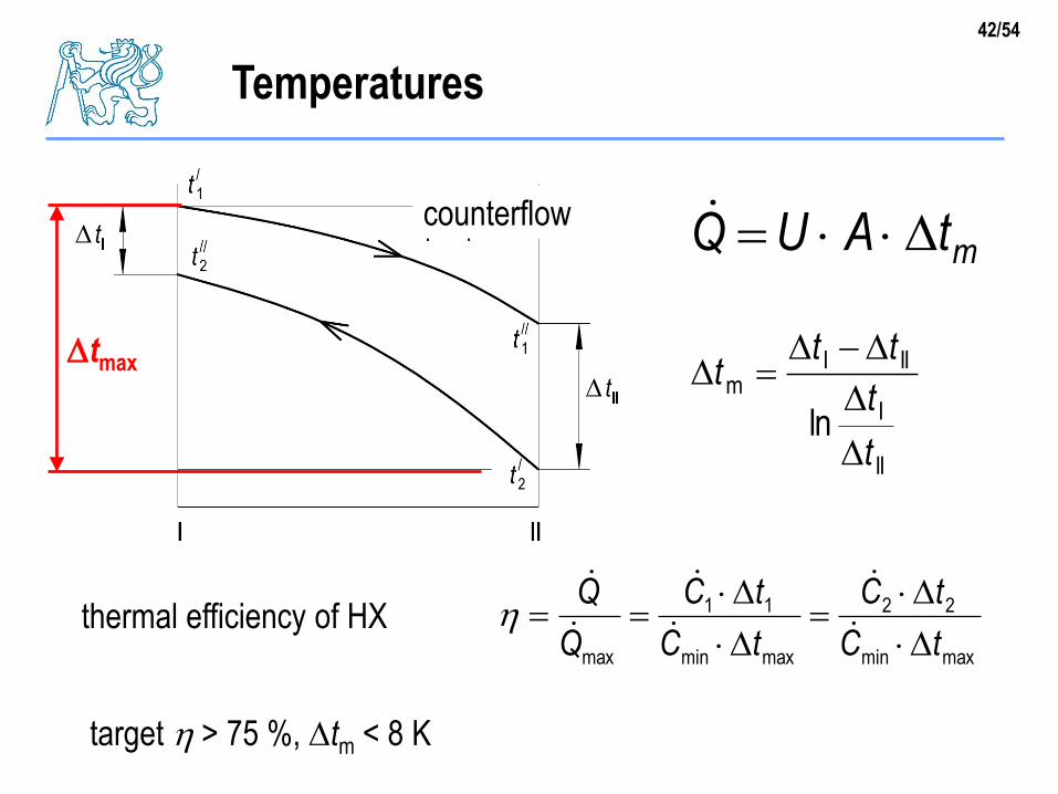
Temperatures
mtAUQ
II
I
IIIm
lnt
t
ttt
maxmin
22
maxmin
11
max tC
tC
tC
tC
Q
Q
target > 75 %, tm < 8 K
thermal efficiency of HX
tmax
counterflow
43/54
defined operation point x dynamic behaviour in real operation
flowrates M1 a M2
given by hydraulic and pumps sizing
result of HX calculation (optimization)
heat power given by solar collector field Qk
temperatures at the input to HX are given by operation
primary (collector) loop
secondary loop
HX sizing = sizing U.A [W/K] – return calculation of temperature
conditions for selected size of HX
Boundary conditions
C6555/1 t
C2015/2 t
44/54
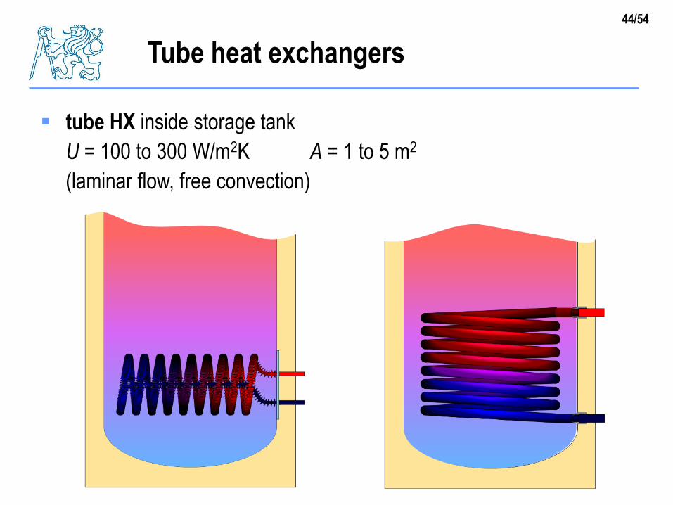
tube HX inside storage tank
U = 100 to 300 W/m2K A = 1 to 5 m2
(laminar flow, free convection)
Tube heat exchangers
45/54
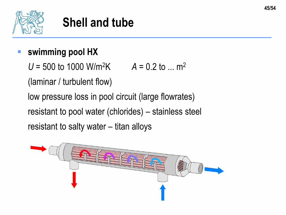
swimming pool HX
U = 500 to 1000 W/m2K A = 0.2 to ... m2
(laminar / turbulent flow)
low pressure loss in pool circuit (large flowrates)
resistant to pool water (chlorides) – stainless steel
resistant to salty water – titan alloys
Shell and tube
46/54
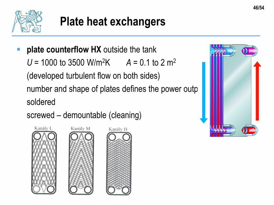
plate counterflow HX outside the tank
U = 1000 to 3500 W/m2K A = 0.1 to 2 m2
(developed turbulent flow on both sides)
number and shape of plates defines the power output
soldered
screwed – demountable (cleaning)
Plate heat exchangers
47/54
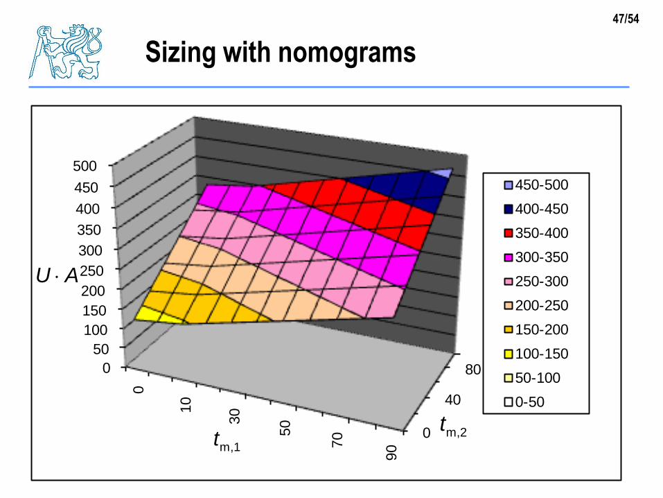
Sizing with nomograms
0
40
800
50
100
150
200
250
300
350
400
450
500
0
10
30
50
70
90
450-500
400-450
350-400
300-350
250-300
200-250
150-200
100-150
50-100
0-50
m,1t m,2t
U A
48/54
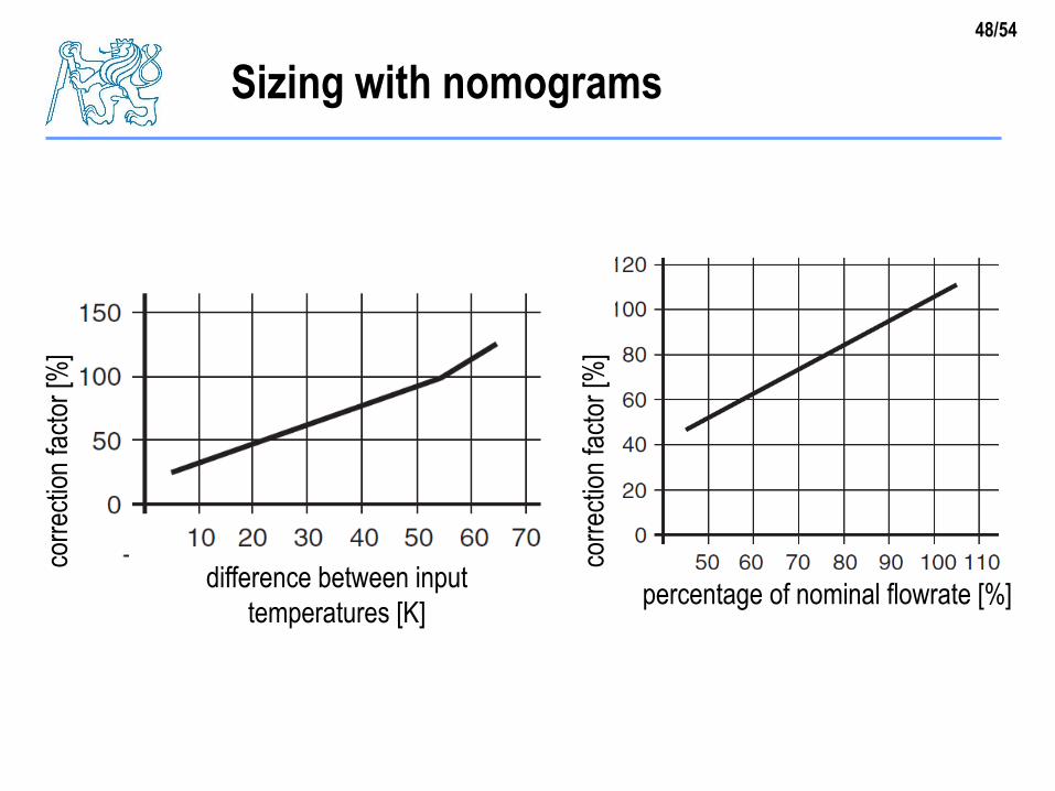
Sizing with nomogramsco
rrec
tion
fact
or [%
]
corr
ectio
n fa
ctor
[%]
difference between input
temperatures [K]percentage of nominal flowrate [%]
49/54
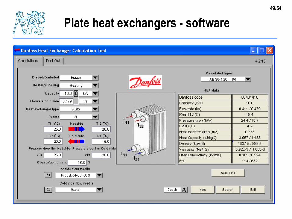
Plate heat exchangers - software
50/54
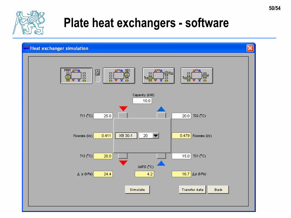
Plate heat exchangers - software
51/54
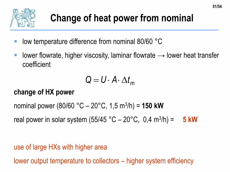
low temperature difference from nominal 80/60 °C
lower flowrate, higher viscosity, laminar flowrate → lower heat transfer
coefficient
change of HX power
nominal power (80/60 °C – 20°C, 1,5 m3/h) = 150 kW
real power in solar system (55/45 °C – 20°C, 0,4 m3/h) = 5 kW
use of large HXs with higher area
lower output temperature to collectors – higher system efficiency
Change of heat power from nominal
mtAUQ
52/54
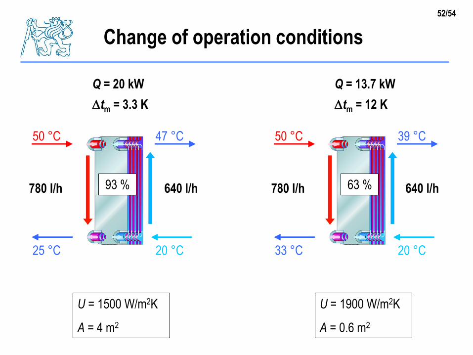
Change of operation conditions
50 °C
25 °C
47 °C
20 °C
Q = 20 kW
780 l/h 640 l/h
U = 1500 W/m2K
A = 4 m2
50 °C
33 °C
39 °C
20 °C
Q = 13.7 kW
780 l/h 640 l/h
U = 1900 W/m2K
A = 0.6 m2
93 % 63 %
tm = 3.3 K tm = 12 K
53/54
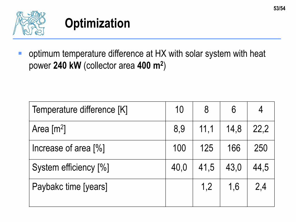
optimum temperature difference at HX with solar system with heat
power 240 kW (collector area 400 m2)
Optimization
Temperature difference [K] 10 8 6 4
Area [m2] 8,9 11,1 14,8 22,2
Increase of area [%] 100 125 166 250
System efficiency [%] 40,0 41,5 43,0 44,5
Paybakc time [years] 1,2 1,6 2,4
54/54
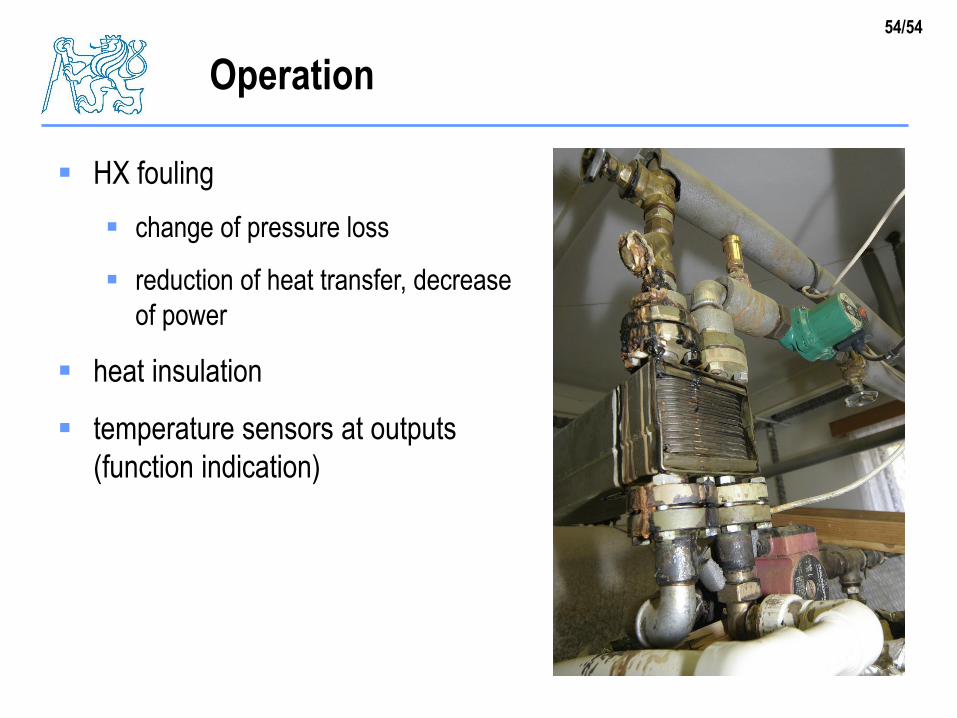
Operation
HX fouling
change of pressure loss
reduction of heat transfer, decrease
of power
heat insulation
temperature sensors at outputs
(function indication)