Embed Size (px)
Citation preview
Cisco 4G LTE-Advanced Configuration
This section contains the following topics:
• Cisco Fourth-Generation LTEAdvanced on the Cisco IR1101 Series Integrated Services Router, on page1
Cisco Fourth-Generation LTE Advanced on the Cisco IR1101Series Integrated Services Router
Cisco LTE Pluggable Modules operate over Fourth-Generation Long-Term Evolution (4G LTE) cellularnetworks and Third-Generation (3G) cellular networks.
The IR1101 offers LTE support through the use of Pluggable Modules. You can find a list of the supportedPluggable Modules in the IR1101 Industrial Integrated Services Router Hardware Installation Guide.
Cisco LTE Pluggable Module support the following 4G/3G modes:
• 4GLTE—4GLTEmobile specification provides multi-megabit bandwidth, more efficient radio network,latency reduction, and improved mobility. LTE solutions target new cellular networks. These networksinitially support up to 100 Mb/s peak rates in the downlink and up to 50 Mb/s peak rates in the uplink.The throughput of these networks is higher than the existing 3G networks
• 3G Evolution High-Speed Packet Access (HSPA/HSPA+)—HSPA is a UMTS-based 3G network. Itsupports High-SpeedDownlink Packet Access (HSDPA) andHigh-SpeedUplink Packet Access (HSUPA)data for improved download and upload speeds. Evolution High-Speed Packet Access (HSPA+) supportsMultiple Input/Multiple Output (MIMO) antenna capability.
• 3GEvolution-DataOptimized (EVDOorDOrA)Mode—EVDO is a 3G telecommunications standardfor the wireless transmission of data through radio signals, typically for broadband Internet access. DOrArefers to EVDO Rev-A. EVDO uses multiplexing techniques including Code Division Multiple Access(CDMA), as well as Time Division Multiple Access (TDMA), to maximize both individual users'throughput and the overall system throughput.
It is important to understand the architecture of the IR1101 series and the relationship between Modems,SIMs, Interface and Controller. The following table helps to illustrate these relationships.
LinePDN InterfaceModem SubSlotSIMControllerRouter
N/ACellular 0/1/0
Cellular 0/1/1
0/10|10/1/0IR1101
Cisco 4G LTE-Advanced Configuration1
LinePDN InterfaceModem SubSlotSIMControllerRouter
N/ACellular 0/3/0
Cellular 0/3/1
0/30|10/3/0IR1101 withExpansionModule
For information on supported antennas and accessories, see the Cisco Industrial Routers and IndustrialWireless Access Points Antenna Guide https://www.cisco.com/c/en/us/td/docs/routers/connectedgrid/antennas/installing-combined/industrial-routers-and-industrial-wireless-antenna-guide.html.
For more information on Cisco 4G LTE Advanced SKUs, faceplates, and LED descriptions, see the CiscoIR1101 Series Integrated Services Router (ISR)Hardware InstallationGuide here:https://www.cisco.com/c/en/us/td/docs/routers/access/1101/hardware/installation/guide/1101hwinst.html
Prerequisites for Configuring Cisco 4G LTE Advanced• If the signal is not good at the router, use the Cisco offered antenna accessories and extension cables toplace the antenna away from router in a better coverage area. Please refer to the RSSI/SNT values asdisplayed through show cellular 0/1/0 all or the LED of the pluggable modem.
• You must have 4G LTE network coverage where your router is physically placed. For a complete list ofsupported carriers.
• You must subscribe to a service plan with a wireless service provider and obtain a Subscriber IdentityModule (SIM) card. Only micro SIM is supported.
• You must install the SIM card before configuring the 4G LTE or router.
• The standalone antenna that supports GPS capabilities must be installed for the GPS feature to work.
Restrictions for Configuring Cisco 4G LTE Advanced• Currently, cellular networks support only user initiated bearer establishment.
• Due to the shared nature of wireless communications, the experienced throughput varies depending onthe number of active users or congestion in a given network.
• Cellular bandwidth is asymmetric with the downlink data rate being greater than the uplink data rate.
• Cellular networks have higher latency compared towired networks. Latency rates depend on the technologyand carrier. Latency also depends on the signal conditions and can be higher because of networkcongestion.
• CDMA-EVDO, CDMA-1xRTT, and GPRS technology modes are not supported.
• Any restrictions that are part of the terms of service from your carrier.
• SMS—Only one text message up to 160 characters to one recipient at a time is supported. Larger textsare automatically truncated to the proper size before being sent.
• It is strongly recommended that you configure SNMP V3 with authentication/privacy.
Cisco 4G LTE-Advanced Configuration2
Cisco 4G LTE-Advanced ConfigurationPrerequisites for Configuring Cisco 4G LTE Advanced
Features not Supported in 4G LTE AdvancedThe following features are not supported on Cisco 4G LTE Advanced on the IR1101, when compared toClassic IOS:
• TTY support or Line
• Chat script/dialer string
• DM log output to USB flash is not supported.
4G LTE-Advanced LEDsLED status can be obtained through the show led CLI, or visually on the pluggable modem card. The followingis an example of the show led CLI:IR1101#show ledSYSTEM LED : Green
Custom LED : Off
VPN LED : Off
ALARM LED : Off
GigabitEthernet0/0/0 LED : OffFastEthernet0/0/1 LED : OffFastEthernet0/0/2 LED : OffFastEthernet0/0/3 LED : OffFastEthernet0/0/4 LED : OffGigabitEthernet0/0/5 LED : On
EM Module digital I/O 1 LED : OffEM Module digital I/O 2 LED : OffEM Module digital I/O 3 LED : OffEM Module digital I/O 4 LED : Off
*System LTE Pluggable*LTE module Enable LED : GreenLTE module SIM 0 LED : GreenLTE module SIM 1 LED : OffLTE module GPS LED : OffLTE module RSSI 0 LED : OnLTE module RSSI 1 LED : OnLTE module RSSI 2 LED : OnLTE module RSSI 3 LED : On
*EM Module LTE Pluggable*LTE module Enable LED : GreenLTE module SIM 0 LED : GreenLTE module SIM 1 LED : OffLTE module GPS LED : OffLTE module RSSI 0 LED : OnLTE module RSSI 1 LED : OnLTE module RSSI 2 LED : OnLTE module RSSI 3 LED : On
The following table describes the LED behavior in 4G LTE-Advanced.
Cisco 4G LTE-Advanced Configuration3
Cisco 4G LTE-Advanced ConfigurationFeatures not Supported in 4G LTE Advanced
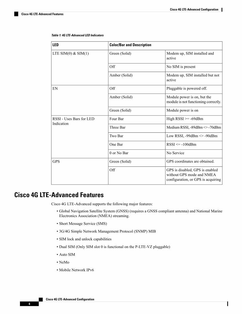
Table 1: 4G LTE-Advanced LED Indicators
Color/Bar and DescriptionLED
Modem up, SIM installed andactive
Green (Solid)LTE SIM(0) & SIM(1)
No SIM is presentOff
Modem up, SIM installed but notactive
Amber (Solid)
Pluggable is powered off.OffEN
Module power is on, but themodule is not functioning correctly.
Amber (Solid)
Module power is onGreen (Solid)
High RSSI >= -69dBmFour BarRSSI - Uses Bars for LEDIndication
MediumRSSI, -89dBm<> -70dBmThree Bar
Low RSSI, -99dBm <> -90dBmTwo Bar
RSSI <= -100dBmOne Bar
No Service0 or No Bar
GPS coordinates are obtained.Green (Solid)GPS
GPS is disabled, GPS is enabledwithout GPS mode and NMEAconfiguration, or GPS is acquiring
Off
Cisco 4G LTE-Advanced FeaturesCisco 4G LTE-Advanced supports the following major features:
• Global Navigation Satellite System (GNSS) (requires a GNSS compliant antenna) and National MarineElectronics Association (NMEA) streaming.
• Short Message Service (SMS)
• 3G/4G Simple Network Management Protocol (SNMP) MIB
• SIM lock and unlock capabilities
• Dual SIM (Only SIM slot 0 is functional on the P-LTE-VZ pluggable)
• Auto SIM
• NeMo
• Mobile Network IPv6
Cisco 4G LTE-Advanced Configuration4
Cisco 4G LTE-Advanced ConfigurationCisco 4G LTE-Advanced Features
• Public Land Mobile Network (PLMN) selection
• IPv6
• Multiple PDN
• LTE Link Recovery
4G GNSS and NMEAActive GNSS is supported on the SubMiniature version A (SMA) port. Active GNSS antenna is supportedonly in the standalone mode. An Active GNSS antenna includes a built-in Low-Noise Amplifier that providessufficient gain to overcome coaxial cable losses while providing the proper signal level to the GNSS receiver.Active GNSS antennae require power from the GNSS receiver SMA port to operate.
National Marine Electronics Association (NMEA) streams GNSS data either from a 4G LTE through a virtualCOM port and a TCP/IP Ethernet connection to any marine device (such as a Windows-based PC) that runsa commercially available GNSS-based application.
The following GNSS and NMEA features are supported on the Cisco 4G LTE-Advanced:
• GNSS standalone mode (satellite-based GNSS)
• Cisco IOS-XE CLI display coordinates.
• External application displays router map location
• Objects in the CISCO-WAN-3G-MIB supports GNSS and NMEA features
• The Cisco 4G LTE-Advanced only support NMEA over IP and uses show commands in the platform
Assisted GNSS mode is not supported.Note
Example: Connecting to a Server Hosting a GPS ApplicationYou can feed the NMEA data to a remote server that hosts the GPS application. The server can be connectedto the router either directly using an Ethernet cable or through a LAN or WAN network. If the applicationsupports serial port, run a serial port emulation program to create a virtual serial port over the LAN or WANconnection.
Microsoft Streets & Trips is a licensed software that you can download from the Microsoft website.Note
To connect a Cisco 4G LTE-Advanced through IP to a PC running Microsoft Streets & Trips, perform thefollowing steps:
1. Connect the PC to the router using an Ethernet cable.
2. Ensure that the PC and router can ping.
3. Launch the serial port redirector on the PC.
Cisco 4G LTE-Advanced Configuration5
Cisco 4G LTE-Advanced Configuration4G GNSS and NMEA
4. Create a virtual serial port that connects to the NMEA port on the router.
5. LaunchMicrosoft Streets & Trips on your PC.
6. Select the GPS Menu.
7. Click Start Tracking.
8. If you have acquired a location fix from the show cellular 0/1/0 gps command output on the router, thecurrent location is plotted on the graph, and a reddish brown dotted cursor with a circle around it is seenon the map.
If you have not acquired a location fix, the Microsoft application times out and disconnects.Note
Dual SIM Card
The P-LTE-VZ pluggable which supports Verizon is a single SIM.Note
SIM card primary slot is selected when router boots up or when NIM reloads. The default slot is 0. If SIMcard is not present in the primary slot, select the alternative slot if SIM card is present.controller cellular 0/1/0lte sim primary slot <slot#>
If the active SIM card loses connectivity to the network a failover to the alternative SIM card slot occurs.
By default the failover timer is 3 minutes. The failover timer can be set from 3 to 7 minutes.controller cellular 0/1/0lte failovertimer <3-7>
You can also manually switch the SIM slot via the command line interface.cellular 0/1/0 lte sim activate slot <0-1>
Auto SIMThe Auto SIM feature detects the SIM and loads the corresponding firmware. For example, if an AT&T SIMis detected, the modem loads the AT&T firmware.
When Auto-SIM is enabled, it is said to be in Auto-SIM mode and when disabled, it is known as Manualmode. In Auto-SIM mode, the modem selects the right carrier firmware from the list of firmware's available.When in manual mode, you can select the firmware manually. Modem resets every time you make a configchange from Auto-SIM enabled to disabled or vice-versa.
The P-LTE-US and P-LTE-GB pluggable modules on the IR1101 support Auto SIM.
Auto SIM is always enabled by default.Note
Cisco 4G LTE-Advanced Configuration6
Cisco 4G LTE-Advanced ConfigurationDual SIM Card
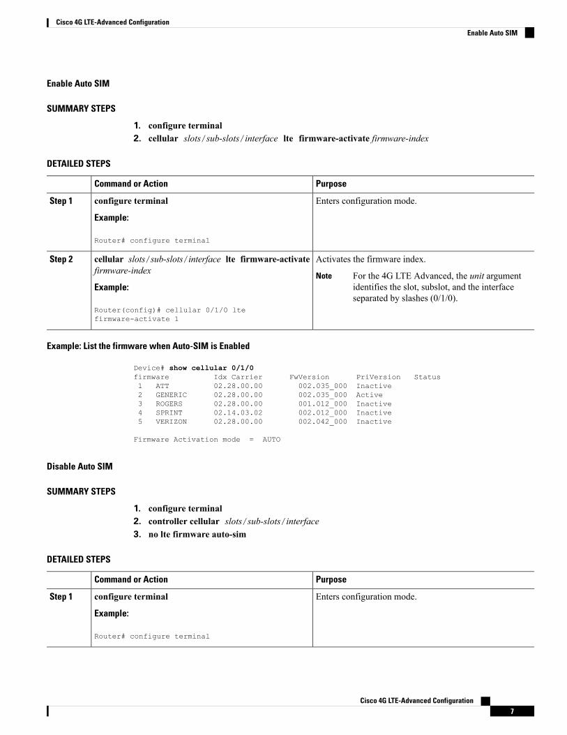
Enable Auto SIM
SUMMARY STEPS
1. configure terminal2. cellular slots/sub-slots/interface lte firmware-activate firmware-index
DETAILED STEPS
PurposeCommand or Action
Enters configuration mode.configure terminal
Example:
Step 1
Router# configure terminal
Activates the firmware index.cellular slots/sub-slots/interface lte firmware-activatefirmware-index
Step 2
For the 4G LTE Advanced, the unit argumentidentifies the slot, subslot, and the interfaceseparated by slashes (0/1/0).
NoteExample:
Router(config)# cellular 0/1/0 ltefirmware-activate 1
Example: List the firmware when Auto-SIM is Enabled
Device# show cellular 0/1/0firmware Idx Carrier FwVersion PriVersion Status1 ATT 02.28.00.00 002.035_000 Inactive2 GENERIC 02.28.00.00 002.035_000 Active3 ROGERS 02.28.00.00 001.012_000 Inactive4 SPRINT 02.14.03.02 002.012_000 Inactive5 VERIZON 02.28.00.00 002.042_000 Inactive
Firmware Activation mode = AUTO
Disable Auto SIM
SUMMARY STEPS
1. configure terminal2. controller cellular slots/sub-slots/interface3. no lte firmware auto-sim
DETAILED STEPS
PurposeCommand or Action
Enters configuration mode.configure terminal
Example:
Step 1
Router# configure terminal
Cisco 4G LTE-Advanced Configuration7
Cisco 4G LTE-Advanced ConfigurationEnable Auto SIM
PurposeCommand or Action
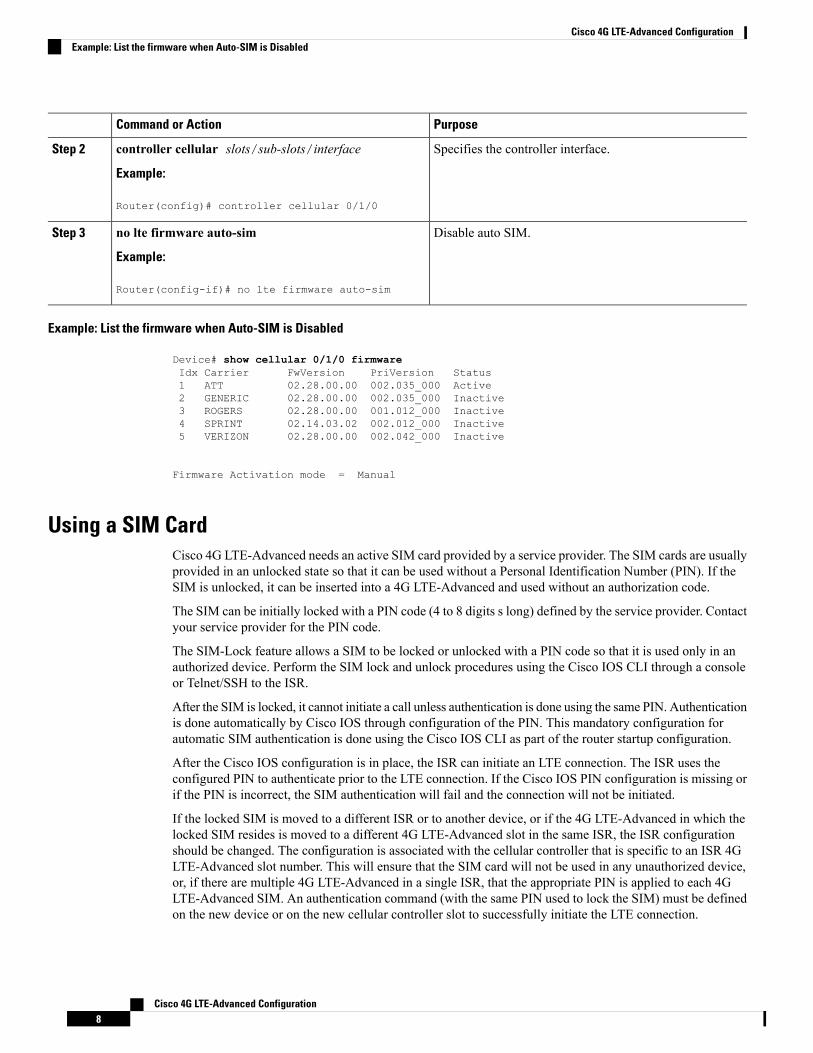
Specifies the controller interface.controller cellular slots/sub-slots/interface
Example:
Step 2
Router(config)# controller cellular 0/1/0
Disable auto SIM.no lte firmware auto-sim
Example:
Step 3
Router(config-if)# no lte firmware auto-sim
Example: List the firmware when Auto-SIM is Disabled
Device# show cellular 0/1/0 firmwareIdx Carrier FwVersion PriVersion Status1 ATT 02.28.00.00 002.035_000 Active2 GENERIC 02.28.00.00 002.035_000 Inactive3 ROGERS 02.28.00.00 001.012_000 Inactive4 SPRINT 02.14.03.02 002.012_000 Inactive5 VERIZON 02.28.00.00 002.042_000 Inactive
Firmware Activation mode = Manual
Using a SIM CardCisco 4G LTE-Advanced needs an active SIM card provided by a service provider. The SIM cards are usuallyprovided in an unlocked state so that it can be used without a Personal Identification Number (PIN). If theSIM is unlocked, it can be inserted into a 4G LTE-Advanced and used without an authorization code.
The SIM can be initially locked with a PIN code (4 to 8 digits s long) defined by the service provider. Contactyour service provider for the PIN code.
The SIM-Lock feature allows a SIM to be locked or unlocked with a PIN code so that it is used only in anauthorized device. Perform the SIM lock and unlock procedures using the Cisco IOS CLI through a consoleor Telnet/SSH to the ISR.
After the SIM is locked, it cannot initiate a call unless authentication is done using the same PIN. Authenticationis done automatically by Cisco IOS through configuration of the PIN. This mandatory configuration forautomatic SIM authentication is done using the Cisco IOS CLI as part of the router startup configuration.
After the Cisco IOS configuration is in place, the ISR can initiate an LTE connection. The ISR uses theconfigured PIN to authenticate prior to the LTE connection. If the Cisco IOS PIN configuration is missing orif the PIN is incorrect, the SIM authentication will fail and the connection will not be initiated.
If the locked SIM is moved to a different ISR or to another device, or if the 4G LTE-Advanced in which thelocked SIM resides is moved to a different 4G LTE-Advanced slot in the same ISR, the ISR configurationshould be changed. The configuration is associated with the cellular controller that is specific to an ISR 4GLTE-Advanced slot number. This will ensure that the SIM card will not be used in any unauthorized device,or, if there are multiple 4G LTE-Advanced in a single ISR, that the appropriate PIN is applied to each 4GLTE-Advanced SIM. An authentication command (with the same PIN used to lock the SIM) must be definedon the new device or on the new cellular controller slot to successfully initiate the LTE connection.
Cisco 4G LTE-Advanced Configuration8
Cisco 4G LTE-Advanced ConfigurationExample: List the firmware when Auto-SIM is Disabled
The following procedures are used to configure a SIM:
It is very important to use the correct PIN after it is configured. The SIM card will be blocked if the wrongPIN is entered three consecutive times on a locked SIM during authentication or when trying to unlock alocked SIM. You can unblock a blocked SIM card using the PUK code. Contact your service provider for thePUK code. Use the cellular <slot> lte sim unblock <PUK code> <new PIN code> command to unblock theSIM.
Caution
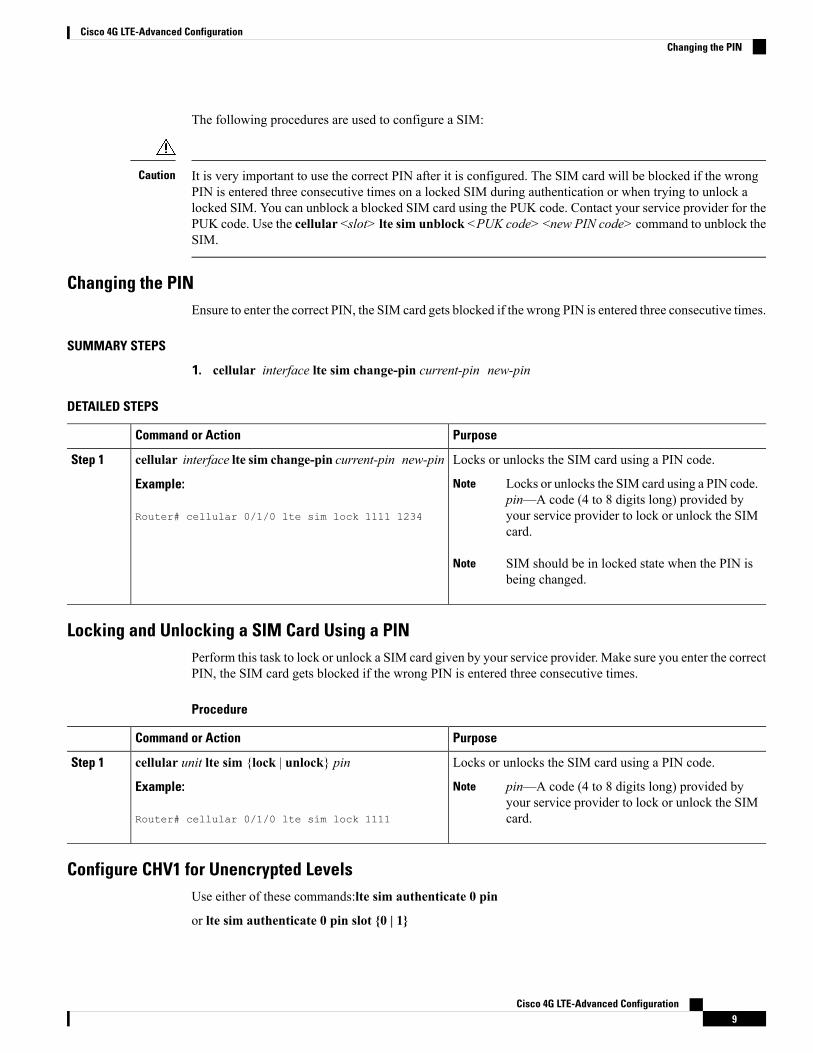
Changing the PINEnsure to enter the correct PIN, the SIM card gets blocked if the wrong PIN is entered three consecutive times.
SUMMARY STEPS
1. cellular interface lte sim change-pin current-pin new-pin
DETAILED STEPS
PurposeCommand or Action
Locks or unlocks the SIM card using a PIN code.cellular interface lte sim change-pin current-pin new-pinStep 1
Example: Locks or unlocks the SIM card using a PIN code.pin—A code (4 to 8 digits long) provided byyour service provider to lock or unlock the SIMcard.
Note
Router# cellular 0/1/0 lte sim lock 1111 1234
SIM should be in locked state when the PIN isbeing changed.
Note
Locking and Unlocking a SIM Card Using a PINPerform this task to lock or unlock a SIM card given by your service provider. Make sure you enter the correctPIN, the SIM card gets blocked if the wrong PIN is entered three consecutive times.
Procedure
PurposeCommand or Action
Locks or unlocks the SIM card using a PIN code.cellular unit lte sim {lock | unlock} pinStep 1
Example: pin—A code (4 to 8 digits long) provided byyour service provider to lock or unlock the SIMcard.
Note
Router# cellular 0/1/0 lte sim lock 1111
Configure CHV1 for Unencrypted LevelsUse either of these commands:lte sim authenticate 0 pin
or lte sim authenticate 0 pin slot {0 | 1}
Cisco 4G LTE-Advanced Configuration9
Cisco 4G LTE-Advanced ConfigurationChanging the PIN
Procedure
PurposeCommand or Action
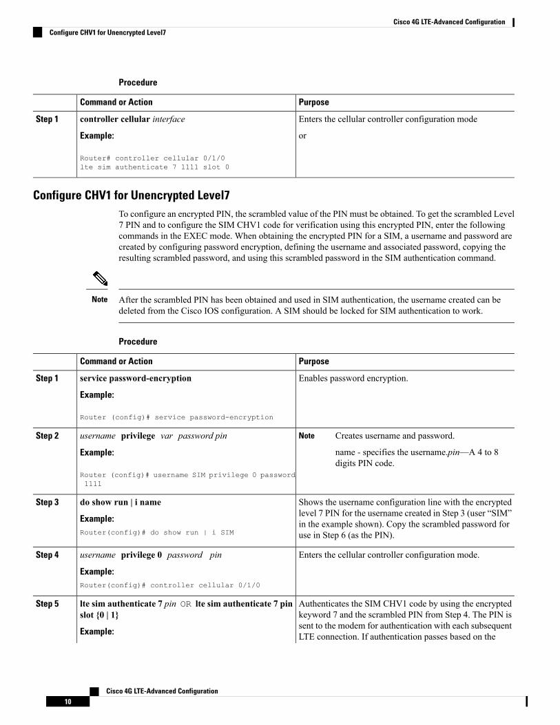
Enters the cellular controller configuration modecontroller cellular interfaceStep 1
Example: or
Router# controller cellular 0/1/0lte sim authenticate 7 1111 slot 0
Configure CHV1 for Unencrypted Level7To configure an encrypted PIN, the scrambled value of the PIN must be obtained. To get the scrambled Level7 PIN and to configure the SIM CHV1 code for verification using this encrypted PIN, enter the followingcommands in the EXEC mode. When obtaining the encrypted PIN for a SIM, a username and password arecreated by configuring password encryption, defining the username and associated password, copying theresulting scrambled password, and using this scrambled password in the SIM authentication command.
After the scrambled PIN has been obtained and used in SIM authentication, the username created can bedeleted from the Cisco IOS configuration. A SIM should be locked for SIM authentication to work.
Note
Procedure
PurposeCommand or Action
Enables password encryption.service password-encryption
Example:
Step 1
Router (config)# service password-encryption
username privilege var password pinStep 2 Creates username and password.
name - specifies the username.pin—A 4 to 8digits PIN code.
Note
Example:
Router (config)# username SIM privilege 0 password1111
Shows the username configuration line with the encryptedlevel 7 PIN for the username created in Step 3 (user “SIM”
do show run | i name
Example:
Step 3
in the example shown). Copy the scrambled password foruse in Step 6 (as the PIN).Router(config)# do show run | i SIM
Enters the cellular controller configuration mode.username privilege 0 password pin
Example:
Step 4
Router(config)# controller cellular 0/1/0
Authenticates the SIM CHV1 code by using the encryptedkeyword 7 and the scrambled PIN from Step 4. The PIN is
lte sim authenticate 7 pin OR lte sim authenticate 7 pinslot {0 | 1}
Step 5
sent to the modem for authentication with each subsequentExample: LTE connection. If authentication passes based on the
Cisco 4G LTE-Advanced Configuration10
Cisco 4G LTE-Advanced ConfigurationConfigure CHV1 for Unencrypted Level7
PurposeCommand or ActionDevice(config-controller)# lte sim authenticate 7055A575E70
configured PIN, the data call is allowed. If authenticationfails, the modem does not initiate the data call.
The slot keyword and its options are availableonly on platforms that supports Dual-SIMfeature.
Note
(Optional) Exits the cellular controller configuration mode.exit
Example:
Step 6
Router(config-controller)# exit
(Optional) Removes the username and password created inStep 3
no usernamename
Example:
Step 7
Router(config-controller)# no username SIM
(Optional) Removes the username and password created inStep 3
no service password-encryptionname
Example:
Step 8
Router(config-controller)# no servicepassword-encryption
Short Message Service (SMS) CapabilitiesCisco 4G LTE-Advanced support receiving, transmitting, archiving, and deleting of SMS messages. Thissupport includes the ability to view up to 25 received texts, and archive more messages in a custom filelocation. SMS is supported on multiple carriers. Cisco 4G LTE-Advanced also have the capability to revertfrom LTE SMS to 3G technology if necessary.
A sending device behind a Cisco 4G LTE-Advanced transmits an SMS text message over the 4G cellular linkthrough cellular towers until it the message reaches the recipient’s router, which then notifies the recipientdevice, such as a cell phone. The receiving device uses the same process to return a reply to the sending device.The following figure describes the flow from a mobile device to a sending device. For SMS transmission towork, end users must have a text-capable device, and optionally, a text plan. If end users do not have a textplan, standard SMS rates apply to their text transmissions.
Cisco 4G LTE-Advanced Configuration11
Cisco 4G LTE-Advanced ConfigurationShort Message Service (SMS) Capabilities
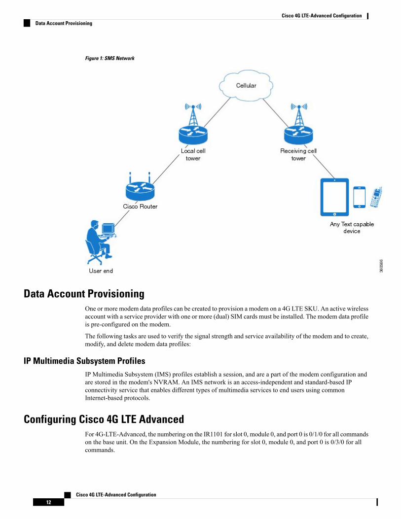
Figure 1: SMS Network
Data Account ProvisioningOne or more modem data profiles can be created to provision a modem on a 4G LTE SKU. An active wirelessaccount with a service provider with one or more (dual) SIM cards must be installed. The modem data profileis pre-configured on the modem.
The following tasks are used to verify the signal strength and service availability of the modem and to create,modify, and delete modem data profiles:
IP Multimedia Subsystem ProfilesIP Multimedia Subsystem (IMS) profiles establish a session, and are a part of the modem configuration andare stored in the modem's NVRAM. An IMS network is an access-independent and standard-based IPconnectivity service that enables different types of multimedia services to end users using commonInternet-based protocols.
Configuring Cisco 4G LTE AdvancedFor 4G-LTE-Advanced, the numbering on the IR1101 for slot 0, module 0, and port 0 is 0/1/0 for all commandson the base unit. On the Expansion Module, the numbering for slot 0, module 0, and port 0 is 0/3/0 for allcommands.
Cisco 4G LTE-Advanced Configuration12
Cisco 4G LTE-Advanced ConfigurationData Account Provisioning
4G modems in the Expansion Module will support the same feature set, including GPS, as supported by thesame modem in the Base Module.
Verifying Modem Signal Strength and Service AvailabilityFor the 4G LTE Advanced, the unit argument identifies the router slot, module slot, and port separated byslashes (0/1/0).
Procedure
PurposeCommand or Action
Displays information about the carrier network, cell site,and available service.
show cellular unit network
Example:
Step 1
Router# show cellular 0/1/0 network
Shows the radio signal strength.show cellular unit radioStep 2
Example: The RSSI should be better than –90 dBm forsteady and reliable connection.
Note
Router# show cellular 0/1/0 radio
Shows information about the modem data profiles created.show cellular unit profile
Example:
Step 3
Router# show cellular 0/1/0 profile
Shows the security information for the modem, such as SIMand modem lock status.
show cellular unit security
Example:
Step 4
Router# show cellular 0/1/0 security
Shows consolidated information about themodem, profilescreated, radio signal strength, network security, and so on.
show cellular unit all
Example:
Step 5
Router# show cellular 0/1/0 all
Guidelines for Creating, Modifying, or Deleting Modem Data Profiles
Customized profiles (Access Point Name(APN) in mobile networks) can be created and used on Cisco 4GLTE Advanced SKU's. Maximum number of profiles that can be created are 16.
Cisco SKU's shipping with specific carrier provisioning file (Can be found in Carrier label under "showcellular <slot> hardware"), default profiles are already populated and can be deployed readily.
In all other cases where profile configurations are not available, separate profiles should be created withrequired parameters.
You can create multiple profiles on Cisco 4G LTE Advanced. The following are the default internet profilenumbers for the modems:
Cisco 4G LTE-Advanced Configuration13
Cisco 4G LTE-Advanced ConfigurationVerifying Modem Signal Strength and Service Availability
Profile NumberModem
Profile 1WP7607 (Global)
Both Profile 1 and Profile 3WP7601 (Verizon)
Profile 1WP7603 (AT&T or other SPs)
Follow these guidelines when you configure a data profile using EXEC mode or Config mode :
• You do not have to make any profile-related changes if your modem comes with a data profile, forinstance, AT&T, Sprint and Verizon.
• If any profile parameter changes are required for a connection type, the changes will likely be carriedout in the default profiles.
• To configure different profile types and use them for a different connection, you can create separateprofiles with different parameters (for instance, APN names). Note that only one profile is active at agiven time.
• Use the show cellular <unit> profile command to view the data profile. An asterisk(*) symbol isdisplayed against the data profile. Double asterisk(**) symbol is displayed against the attach profile.
• The data profile is used to set up a data call. If you want to use a different profile, that profile needs tobe made the default one. Use the lte sim data-profile number command to change the default profileunder controller cellular 0/1/0.
Creating, Modifying, or Deleting Data Profiles Using EXEC Mode
Customized profiles (Access Point Name(APN) in mobile networks) can be created and used on Cisco 4GLTE Advanced SKU's. Maximum number of profiles that can be created are 16.
Cisco SKU's shipping with specific carrier provisioning file (can be found in carrier label under show cellularslot hardware, default profiles are already populated and can be deployed readily.
For the 4G LTE Advanced, the unit argument identifies the router slot, module slot, and port separated byslashes (0/1/0).
Note
Procedure
PurposeCommand or Action
Creates, modifies, or deletes a modem data profile in theprivileged EXEC mode.
cellular unit lte profile [create | delete] profile-number[apn [authentication [username password [bearer-type]]]]
Step 1
Example: • The profile-number argument specifies the profilenumber created for the modem.
Router# cellular 0/1/0 lte profile create 2 apn.compap username pwd ipv4
• (Optional) The apn argument specifies an Access PointName (APN). An APN is provided by your serviceprovider. Only a single APN can be specified for asingle profile.
• (Optional) The authentication parameter specifies theauthentication type used. Acceptable parameters arechap, none (no authentication), pap, and pap_chap(PAP or CHAP authentication).
Cisco 4G LTE-Advanced Configuration14
Cisco 4G LTE-Advanced ConfigurationCreating, Modifying, or Deleting Data Profiles Using EXEC Mode
PurposeCommand or Action
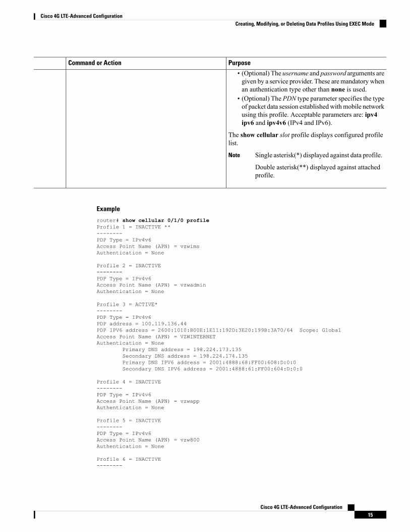
• (Optional) The username and password arguments aregiven by a service provider. These are mandatory whenan authentication type other than none is used.
• (Optional) The PDN type parameter specifies the typeof packet data session established with mobile networkusing this profile. Acceptable parameters are: ipv4ipv6 and ipv4v6 (IPv4 and IPv6).
The show cellular slot profile displays configured profilelist.
Single asterisk(*) displayed against data profile.
Double asterisk(**) displayed against attachedprofile.
Note
Example
router# show cellular 0/1/0 profileProfile 1 = INACTIVE **--------PDP Type = IPv4v6Access Point Name (APN) = vzwimsAuthentication = None
Profile 2 = INACTIVE--------PDP Type = IPv4v6Access Point Name (APN) = vzwadminAuthentication = None
Profile 3 = ACTIVE*--------PDP Type = IPv4v6PDP address = 100.119.136.44PDP IPV6 address = 2600:1010:B00E:1E11:192D:3E20:199B:3A70/64 Scope: GlobalAccess Point Name (APN) = VZWINTERNETAuthentication = None
Primary DNS address = 198.224.173.135Secondary DNS address = 198.224.174.135Primary DNS IPV6 address = 2001:4888:68:FF00:608:D:0:0Secondary DNS IPV6 address = 2001:4888:61:FF00:604:D:0:0
Profile 4 = INACTIVE--------PDP Type = IPv4v6Access Point Name (APN) = vzwappAuthentication = None
Profile 5 = INACTIVE--------PDP Type = IPv4v6Access Point Name (APN) = vzw800Authentication = None
Profile 6 = INACTIVE--------
Cisco 4G LTE-Advanced Configuration15
Cisco 4G LTE-Advanced ConfigurationCreating, Modifying, or Deleting Data Profiles Using EXEC Mode
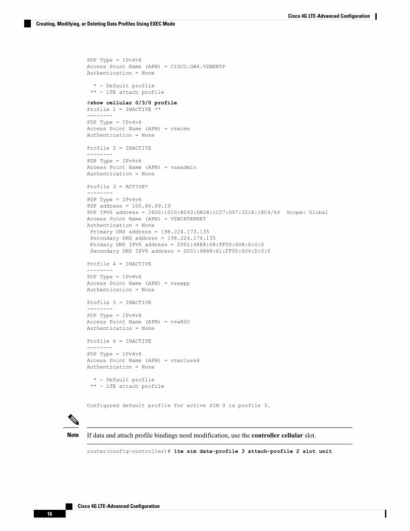
PDP Type = IPv4v6Access Point Name (APN) = CISCO.GW4.VZWENTPAuthentication = None
* - Default profile** - LTE attach profile
#show cellular 0/3/0 profileProfile 1 = INACTIVE **--------PDP Type = IPv4v6Access Point Name (APN) = vzwimsAuthentication = None
Profile 2 = INACTIVE--------PDP Type = IPv4v6Access Point Name (APN) = vzwadminAuthentication = None
Profile 3 = ACTIVE*--------PDP Type = IPv4v6PDP address = 100.86.69.19PDP IPV6 address = 2600:1010:B040:DA58:1C27:D97:321E:18C4/64 Scope: GlobalAccess Point Name (APN) = VZWINTERNETAuthentication = NonePrimary DNS address = 198.224.173.135Secondary DNS address = 198.224.174.135Primary DNS IPV6 address = 2001:4888:68:FF00:608:D:0:0Secondary DNS IPV6 address = 2001:4888:61:FF00:604:D:0:0
Profile 4 = INACTIVE--------PDP Type = IPv4v6Access Point Name (APN) = vzwappAuthentication = None
Profile 5 = INACTIVE--------PDP Type = IPv4v6Access Point Name (APN) = vzw800Authentication = None
Profile 6 = INACTIVE--------PDP Type = IPv4v6Access Point Name (APN) = vzwclass6Authentication = None
* - Default profile** - LTE attach profile
Configured default profile for active SIM 0 is profile 3.
If data and attach profile bindings need modification, use the controller cellular slot.Note
router(config-controller)# lte sim data-profile 3 attach-profile 2 slot unit
Cisco 4G LTE-Advanced Configuration16
Cisco 4G LTE-Advanced ConfigurationCreating, Modifying, or Deleting Data Profiles Using EXEC Mode
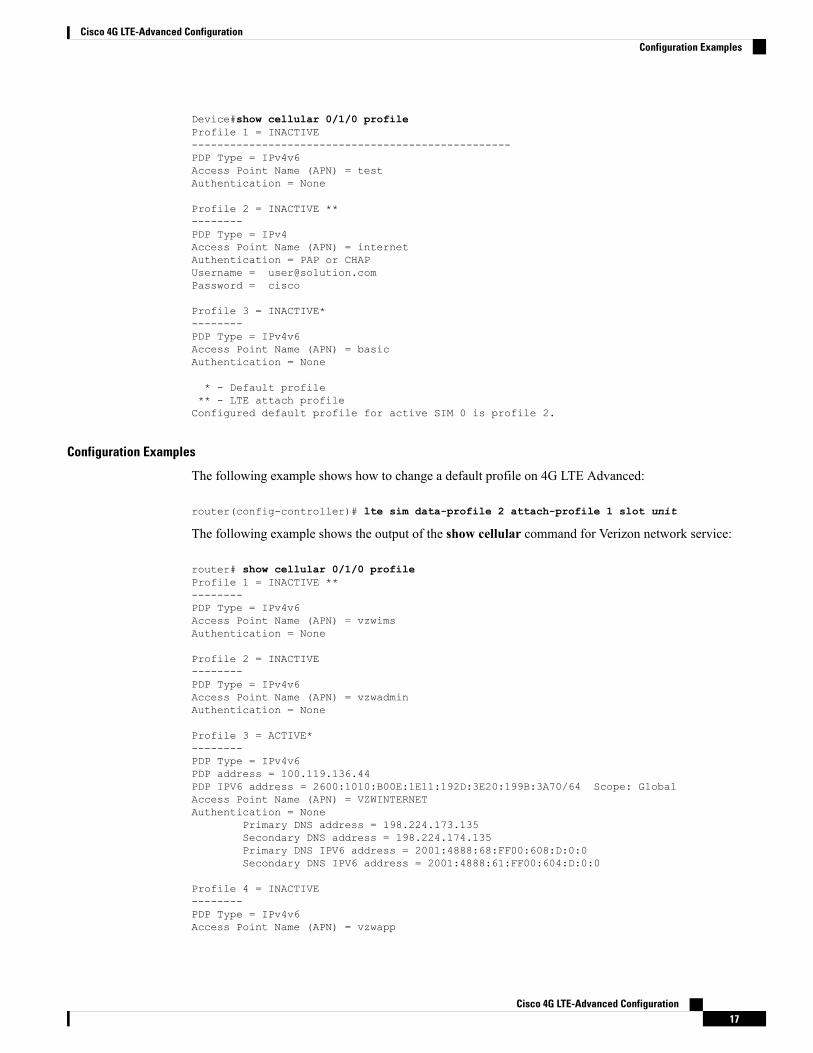
Device#show cellular 0/1/0 profileProfile 1 = INACTIVE--------------------------------------------------PDP Type = IPv4v6Access Point Name (APN) = testAuthentication = None
Profile 2 = INACTIVE **--------PDP Type = IPv4Access Point Name (APN) = internetAuthentication = PAP or CHAPUsername = [email protected] = cisco
Profile 3 = INACTIVE*--------PDP Type = IPv4v6Access Point Name (APN) = basicAuthentication = None
* - Default profile** - LTE attach profileConfigured default profile for active SIM 0 is profile 2.
Configuration Examples
The following example shows how to change a default profile on 4G LTE Advanced:
router(config-controller)# lte sim data-profile 2 attach-profile 1 slot unit
The following example shows the output of the show cellular command for Verizon network service:
router# show cellular 0/1/0 profileProfile 1 = INACTIVE **--------PDP Type = IPv4v6Access Point Name (APN) = vzwimsAuthentication = None
Profile 2 = INACTIVE--------PDP Type = IPv4v6Access Point Name (APN) = vzwadminAuthentication = None
Profile 3 = ACTIVE*--------PDP Type = IPv4v6PDP address = 100.119.136.44PDP IPV6 address = 2600:1010:B00E:1E11:192D:3E20:199B:3A70/64 Scope: GlobalAccess Point Name (APN) = VZWINTERNETAuthentication = None
Primary DNS address = 198.224.173.135Secondary DNS address = 198.224.174.135Primary DNS IPV6 address = 2001:4888:68:FF00:608:D:0:0Secondary DNS IPV6 address = 2001:4888:61:FF00:604:D:0:0
Profile 4 = INACTIVE--------PDP Type = IPv4v6Access Point Name (APN) = vzwapp
Cisco 4G LTE-Advanced Configuration17
Cisco 4G LTE-Advanced ConfigurationConfiguration Examples
Authentication = None
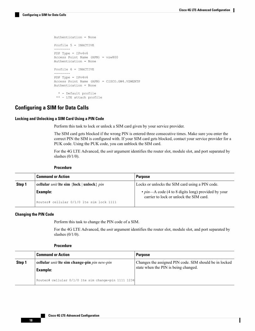
Profile 5 = INACTIVE--------PDP Type = IPv4v6Access Point Name (APN) = vzw800Authentication = None
Profile 6 = INACTIVE--------PDP Type = IPv4v6Access Point Name (APN) = CISCO.GW4.VZWENTPAuthentication = None
* - Default profile** - LTE attach profile
Configuring a SIM for Data Calls
Locking and Unlocking a SIM Card Using a PIN Code
Perform this task to lock or unlock a SIM card given by your service provider.
The SIM card gets blocked if the wrong PIN is entered three consecutive times. Make sure you enter thecorrect PIN the SIM is configured with. If your SIM card gets blocked, contact your service provider for aPUK code. Using the PUK code, you can unblock the SIM card.
For the 4G LTE Advanced, the unit argument identifies the router slot, module slot, and port separated byslashes (0/1/0).
Procedure
PurposeCommand or Action
Locks or unlocks the SIM card using a PIN code.cellular unit lte sim {lock | unlock} pinStep 1
Example: • pin—A code (4 to 8 digits long) provided by yourcarrier to lock or unlock the SIM card.
Router# cellular 0/1/0 lte sim lock 1111
Changing the PIN Code
Perform this task to change the PIN code of a SIM.
For the 4G LTE Advanced, the unit argument identifies the router slot, module slot, and port separated byslashes (0/1/0).
Procedure
PurposeCommand or Action
Changes the assigned PIN code. SIM should be in lockedstate when the PIN is being changed.
cellular unit lte sim change-pin pin new-pin
Example:
Step 1
Router# cellular 0/1/0 lte sim change-pin 1111 1234
Cisco 4G LTE-Advanced Configuration18
Cisco 4G LTE-Advanced ConfigurationConfiguring a SIM for Data Calls
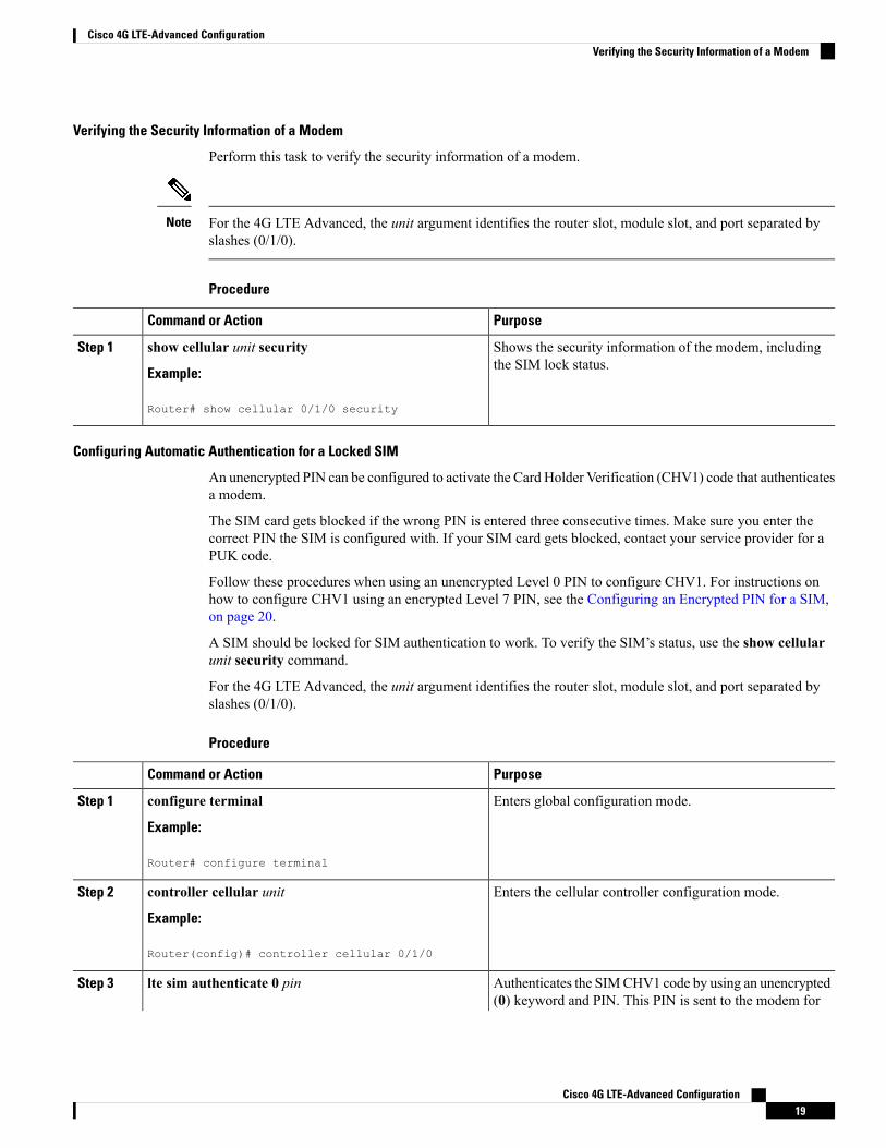
Verifying the Security Information of a Modem
Perform this task to verify the security information of a modem.
For the 4G LTE Advanced, the unit argument identifies the router slot, module slot, and port separated byslashes (0/1/0).
Note
Procedure
PurposeCommand or Action
Shows the security information of the modem, includingthe SIM lock status.
show cellular unit security
Example:
Step 1
Router# show cellular 0/1/0 security
Configuring Automatic Authentication for a Locked SIM
An unencrypted PIN can be configured to activate the Card Holder Verification (CHV1) code that authenticatesa modem.
The SIM card gets blocked if the wrong PIN is entered three consecutive times. Make sure you enter thecorrect PIN the SIM is configured with. If your SIM card gets blocked, contact your service provider for aPUK code.
Follow these procedures when using an unencrypted Level 0 PIN to configure CHV1. For instructions onhow to configure CHV1 using an encrypted Level 7 PIN, see the Configuring an Encrypted PIN for a SIM,on page 20.
A SIM should be locked for SIM authentication to work. To verify the SIM’s status, use the show cellularunit security command.
For the 4G LTE Advanced, the unit argument identifies the router slot, module slot, and port separated byslashes (0/1/0).
Procedure
PurposeCommand or Action
Enters global configuration mode.configure terminal
Example:
Step 1
Router# configure terminal
Enters the cellular controller configuration mode.controller cellular unit
Example:
Step 2
Router(config)# controller cellular 0/1/0
Authenticates the SIMCHV1 code by using an unencrypted(0) keyword and PIN. This PIN is sent to the modem for
lte sim authenticate 0 pinStep 3
Cisco 4G LTE-Advanced Configuration19
Cisco 4G LTE-Advanced ConfigurationVerifying the Security Information of a Modem
PurposeCommand or Action
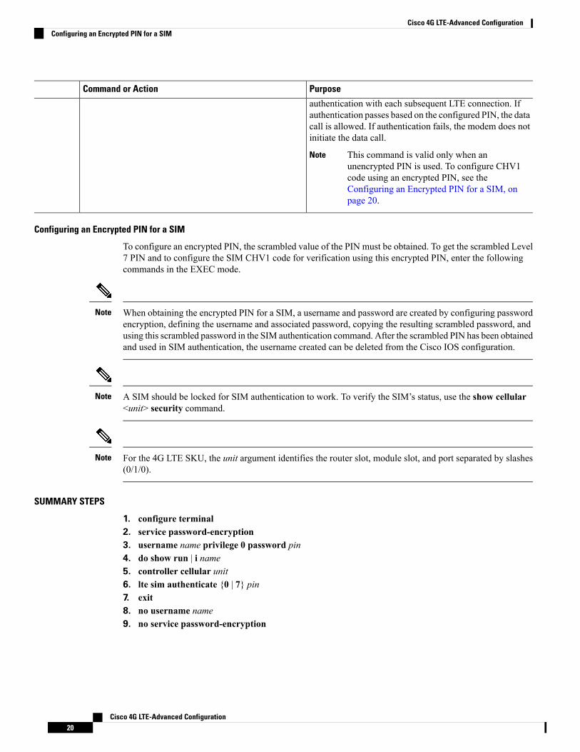
authentication with each subsequent LTE connection. Ifauthentication passes based on the configured PIN, the datacall is allowed. If authentication fails, the modem does notinitiate the data call.
This command is valid only when anunencrypted PIN is used. To configure CHV1code using an encrypted PIN, see theConfiguring an Encrypted PIN for a SIM, onpage 20.
Note
Configuring an Encrypted PIN for a SIM
To configure an encrypted PIN, the scrambled value of the PIN must be obtained. To get the scrambled Level7 PIN and to configure the SIM CHV1 code for verification using this encrypted PIN, enter the followingcommands in the EXEC mode.
When obtaining the encrypted PIN for a SIM, a username and password are created by configuring passwordencryption, defining the username and associated password, copying the resulting scrambled password, andusing this scrambled password in the SIM authentication command. After the scrambled PIN has been obtainedand used in SIM authentication, the username created can be deleted from the Cisco IOS configuration.
Note
A SIM should be locked for SIM authentication to work. To verify the SIM’s status, use the show cellular<unit> security command.
Note
For the 4G LTE SKU, the unit argument identifies the router slot, module slot, and port separated by slashes(0/1/0).
Note
SUMMARY STEPS
1. configure terminal2. service password-encryption3. username name privilege 0 password pin4. do show run | i name5. controller cellular unit6. lte sim authenticate {0 | 7} pin7. exit8. no username name9. no service password-encryption
Cisco 4G LTE-Advanced Configuration20
Cisco 4G LTE-Advanced ConfigurationConfiguring an Encrypted PIN for a SIM
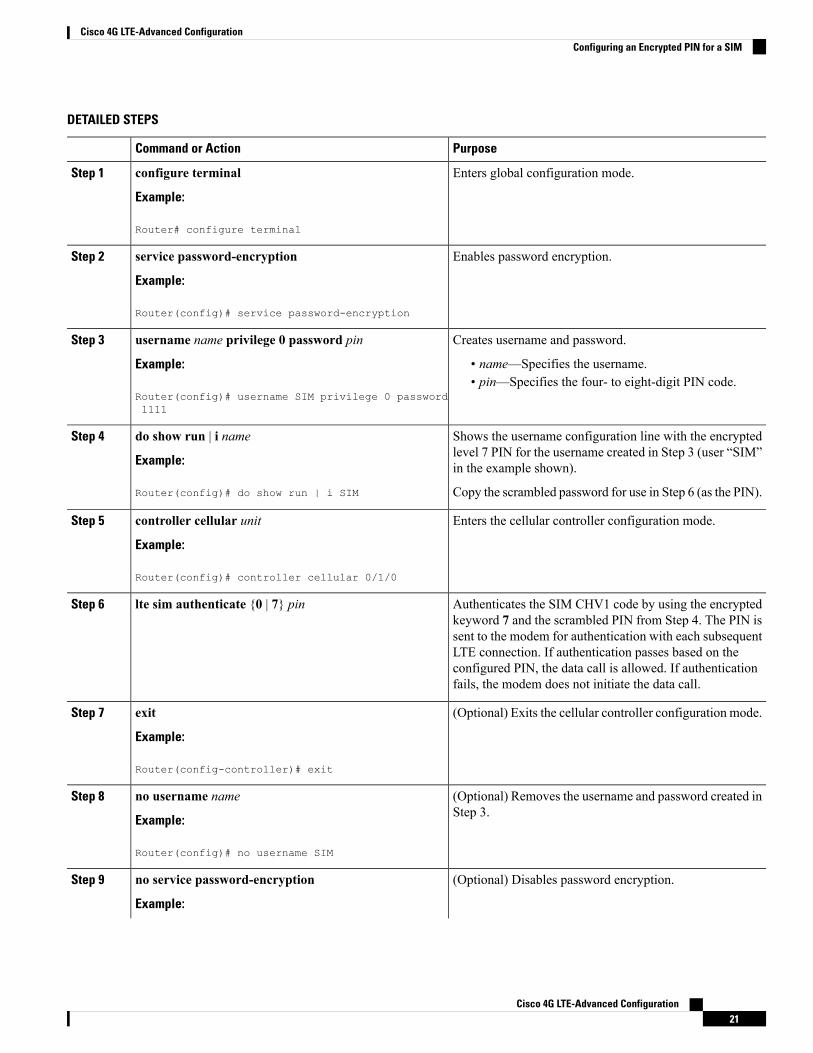
DETAILED STEPS
PurposeCommand or Action
Enters global configuration mode.configure terminal
Example:
Step 1
Router# configure terminal
Enables password encryption.service password-encryption
Example:
Step 2
Router(config)# service password-encryption
Creates username and password.username name privilege 0 password pinStep 3
Example: • name—Specifies the username.• pin—Specifies the four- to eight-digit PIN code.
Router(config)# username SIM privilege 0 password1111
Shows the username configuration line with the encryptedlevel 7 PIN for the username created in Step 3 (user “SIM”in the example shown).
do show run | i name
Example:
Router(config)# do show run | i SIM
Step 4
Copy the scrambled password for use in Step 6 (as the PIN).
Enters the cellular controller configuration mode.controller cellular unit
Example:
Step 5
Router(config)# controller cellular 0/1/0
Authenticates the SIM CHV1 code by using the encryptedkeyword 7 and the scrambled PIN from Step 4. The PIN is
lte sim authenticate {0 | 7} pinStep 6
sent to the modem for authentication with each subsequentLTE connection. If authentication passes based on theconfigured PIN, the data call is allowed. If authenticationfails, the modem does not initiate the data call.
(Optional) Exits the cellular controller configuration mode.exit
Example:
Step 7
Router(config-controller)# exit
(Optional) Removes the username and password created inStep 3.
no username name
Example:
Step 8
Router(config)# no username SIM
(Optional) Disables password encryption.no service password-encryption
Example:
Step 9
Cisco 4G LTE-Advanced Configuration21
Cisco 4G LTE-Advanced ConfigurationConfiguring an Encrypted PIN for a SIM
PurposeCommand or Action
Router(config)# no service password-encryption
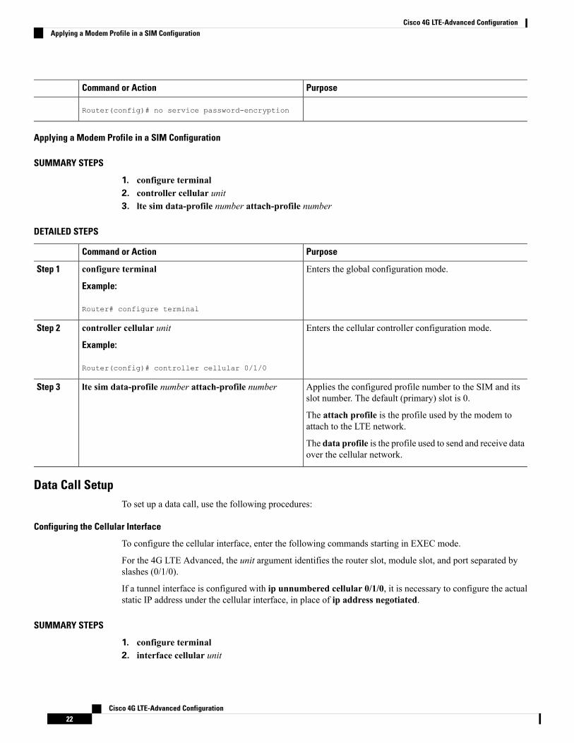
Applying a Modem Profile in a SIM Configuration
SUMMARY STEPS
1. configure terminal2. controller cellular unit3. lte sim data-profile number attach-profile number
DETAILED STEPS
PurposeCommand or Action
Enters the global configuration mode.configure terminal
Example:
Step 1
Router# configure terminal
Enters the cellular controller configuration mode.controller cellular unit
Example:
Step 2
Router(config)# controller cellular 0/1/0
Applies the configured profile number to the SIM and itsslot number. The default (primary) slot is 0.
lte sim data-profile number attach-profile numberStep 3
The attach profile is the profile used by the modem toattach to the LTE network.
The data profile is the profile used to send and receive dataover the cellular network.
Data Call SetupTo set up a data call, use the following procedures:
Configuring the Cellular Interface
To configure the cellular interface, enter the following commands starting in EXEC mode.
For the 4G LTE Advanced, the unit argument identifies the router slot, module slot, and port separated byslashes (0/1/0).
If a tunnel interface is configured with ip unnumbered cellular 0/1/0, it is necessary to configure the actualstatic IP address under the cellular interface, in place of ip address negotiated.
SUMMARY STEPS
1. configure terminal2. interface cellular unit
Cisco 4G LTE-Advanced Configuration22
Cisco 4G LTE-Advanced ConfigurationApplying a Modem Profile in a SIM Configuration
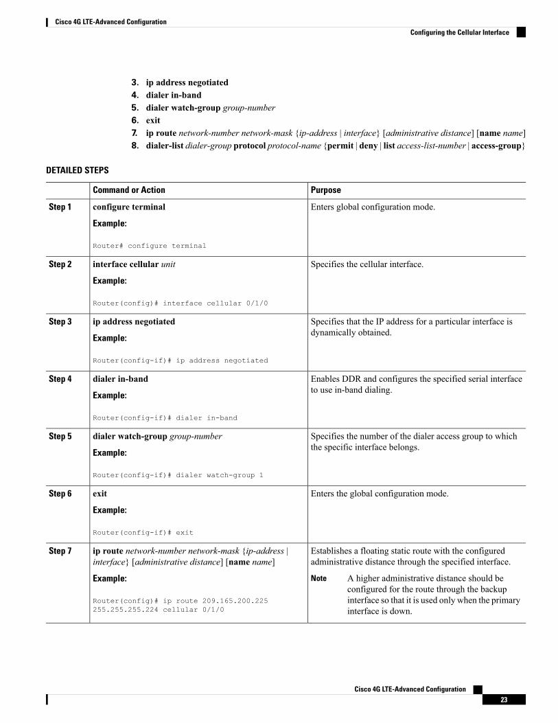
3. ip address negotiated4. dialer in-band5. dialer watch-group group-number6. exit7. ip route network-number network-mask {ip-address | interface} [administrative distance] [name name]8. dialer-list dialer-group protocol protocol-name {permit | deny | list access-list-number | access-group}
DETAILED STEPS
PurposeCommand or Action
Enters global configuration mode.configure terminal
Example:
Step 1
Router# configure terminal
Specifies the cellular interface.interface cellular unit
Example:
Step 2
Router(config)# interface cellular 0/1/0
Specifies that the IP address for a particular interface isdynamically obtained.
ip address negotiated
Example:
Step 3
Router(config-if)# ip address negotiated
Enables DDR and configures the specified serial interfaceto use in-band dialing.
dialer in-band
Example:
Step 4
Router(config-if)# dialer in-band
Specifies the number of the dialer access group to whichthe specific interface belongs.
dialer watch-group group-number
Example:
Step 5
Router(config-if)# dialer watch-group 1
Enters the global configuration mode.exit
Example:
Step 6
Router(config-if)# exit
Establishes a floating static route with the configuredadministrative distance through the specified interface.
ip route network-number network-mask {ip-address |interface} [administrative distance] [name name]
Step 7
Example: A higher administrative distance should beconfigured for the route through the backupinterface so that it is used only when the primaryinterface is down.
Note
Router(config)# ip route 209.165.200.225255.255.255.224 cellular 0/1/0
Cisco 4G LTE-Advanced Configuration23
Cisco 4G LTE-Advanced ConfigurationConfiguring the Cellular Interface
PurposeCommand or Action
Creates a dialer list for traffic of interest and permits accessto an entire protocol.
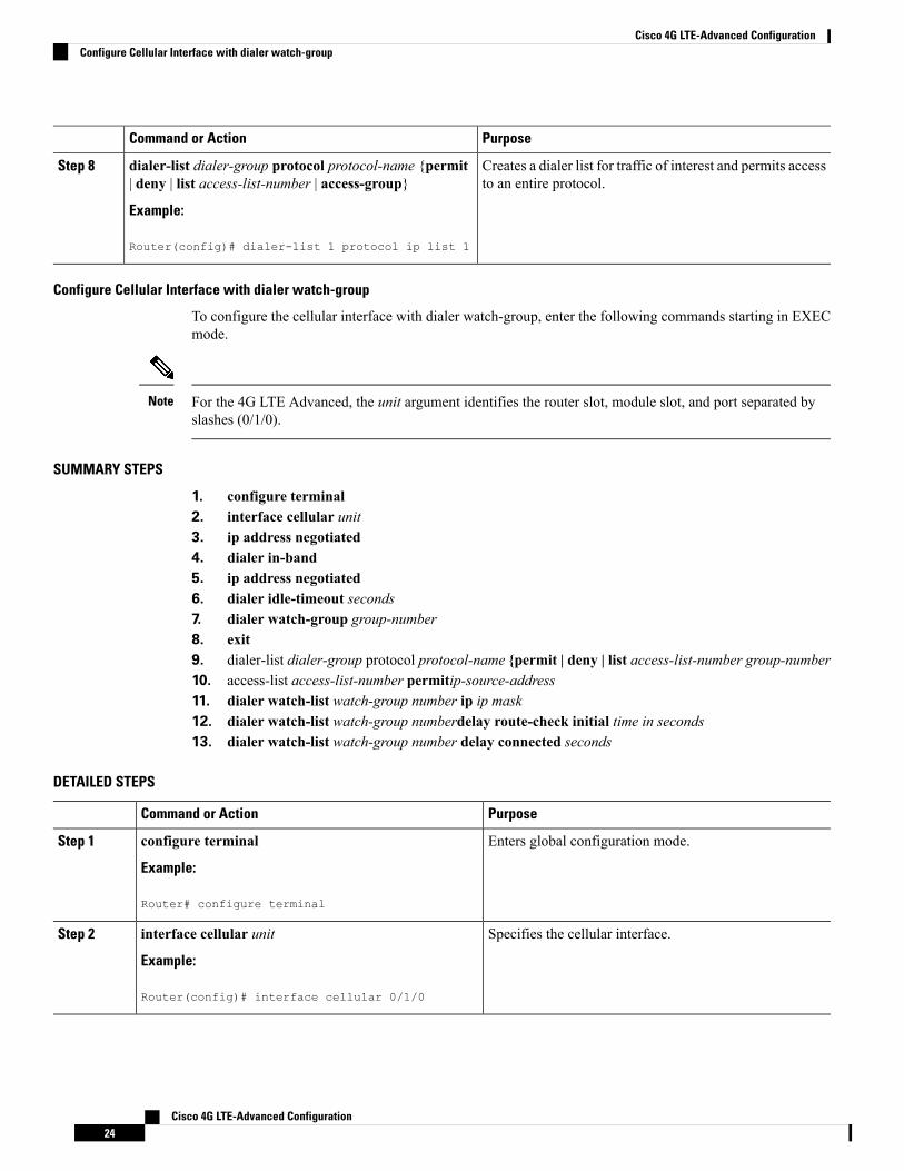
dialer-list dialer-group protocol protocol-name {permit| deny | list access-list-number | access-group}
Example:
Step 8
Router(config)# dialer-list 1 protocol ip list 1
Configure Cellular Interface with dialer watch-group
To configure the cellular interface with dialer watch-group, enter the following commands starting in EXECmode.
For the 4G LTE Advanced, the unit argument identifies the router slot, module slot, and port separated byslashes (0/1/0).
Note
SUMMARY STEPS
1. configure terminal2. interface cellular unit3. ip address negotiated4. dialer in-band5. ip address negotiated6. dialer idle-timeout seconds7. dialer watch-group group-number8. exit9. dialer-list dialer-group protocol protocol-name {permit | deny | list access-list-number group-number10. access-list access-list-number permitip-source-address11. dialer watch-list watch-group number ip ip mask12. dialer watch-list watch-group numberdelay route-check initial time in seconds13. dialer watch-list watch-group number delay connected seconds
DETAILED STEPS
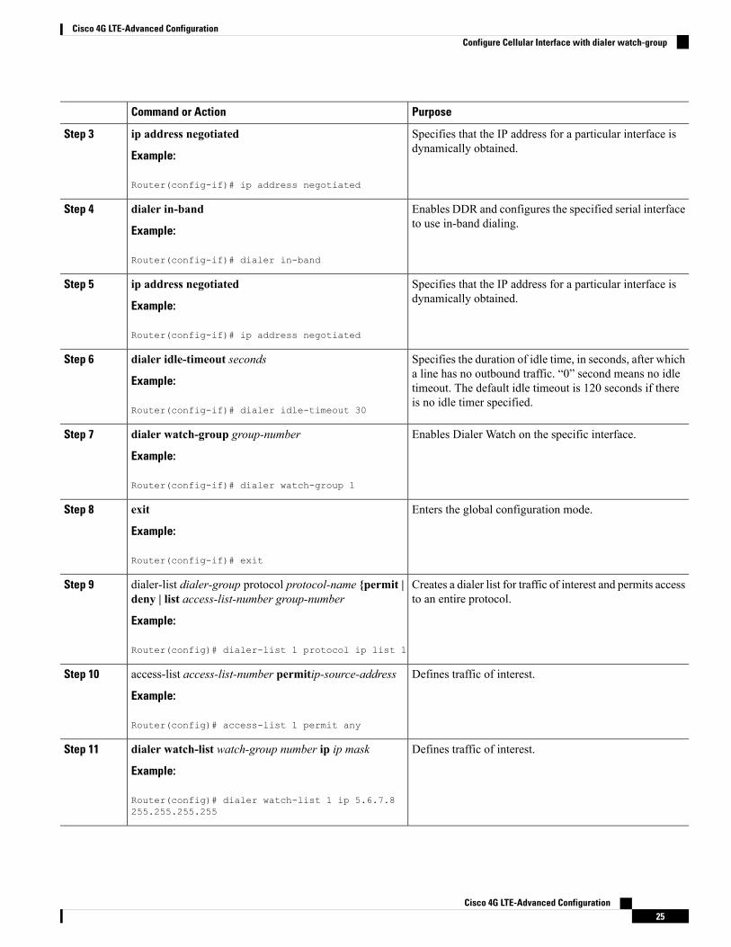
PurposeCommand or Action
Enters global configuration mode.configure terminal
Example:
Step 1
Router# configure terminal
Specifies the cellular interface.interface cellular unit
Example:
Step 2
Router(config)# interface cellular 0/1/0
Cisco 4G LTE-Advanced Configuration24
Cisco 4G LTE-Advanced ConfigurationConfigure Cellular Interface with dialer watch-group
PurposeCommand or Action
Specifies that the IP address for a particular interface isdynamically obtained.
ip address negotiated
Example:
Step 3
Router(config-if)# ip address negotiated
Enables DDR and configures the specified serial interfaceto use in-band dialing.
dialer in-band
Example:
Step 4
Router(config-if)# dialer in-band
Specifies that the IP address for a particular interface isdynamically obtained.
ip address negotiated
Example:
Step 5
Router(config-if)# ip address negotiated
Specifies the duration of idle time, in seconds, after whicha line has no outbound traffic. “0” second means no idle
dialer idle-timeout seconds
Example:
Step 6
timeout. The default idle timeout is 120 seconds if thereis no idle timer specified.
Router(config-if)# dialer idle-timeout 30
Enables Dialer Watch on the specific interface.dialer watch-group group-number
Example:
Step 7
Router(config-if)# dialer watch-group 1
Enters the global configuration mode.exit
Example:
Step 8
Router(config-if)# exit
Creates a dialer list for traffic of interest and permits accessto an entire protocol.
dialer-list dialer-group protocol protocol-name {permit |deny | list access-list-number group-number
Example:
Step 9
Router(config)# dialer-list 1 protocol ip list 1
Defines traffic of interest.access-list access-list-number permitip-source-address
Example:
Step 10
Router(config)# access-list 1 permit any
Defines traffic of interest.dialer watch-list watch-group number ip ip mask
Example:
Step 11
Router(config)# dialer watch-list 1 ip 5.6.7.8255.255.255.255
Cisco 4G LTE-Advanced Configuration25
Cisco 4G LTE-Advanced ConfigurationConfigure Cellular Interface with dialer watch-group
PurposeCommand or Action
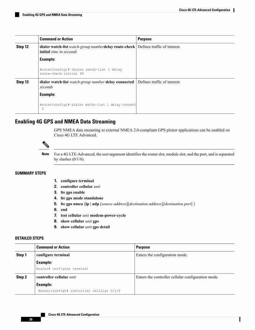
Defines traffic of interest.dialer watch-listwatch-group numberdelay route-checkinitial time in seconds
Step 12
Example:
Router(config)# dialer watch-list 1 delayroute-check initial 60
Defines traffic of interest.dialer watch-list watch-group number delay connectedseconds
Step 13
Example:
Router(config)# dialer watch-list 1 delay connect1
Enabling 4G GPS and NMEA Data StreamingGPS NMEA data streaming to external NMEA 2.0-compliant GPS plotter applications can be enabled onCisco 4G LTE Advanced.
For a 4G LTE-Advanced, the unit argument identifies the router slot, module slot, and the port, and is separatedby slashes (0/1/0).
Note
SUMMARY STEPS
1. configure terminal2. controller cellular unit3. lte gps enable4. lte gps mode standalone5. lte gps nmea {ip | udp [source address][destination address][destination port] }6. end7. test cellular unitmodem-power-cycle8. show cellular unit gps9. show cellular unit gps detail
DETAILED STEPS
PurposeCommand or Action
Enters the configuration mode.configure terminal
Example:
Step 1
Router# configure terminal
Enters the controller cellular configuration mode.controller cellular unit
Example:
Step 2
Router(config)# controller cellular 0/1/0
Cisco 4G LTE-Advanced Configuration26
Cisco 4G LTE-Advanced ConfigurationEnabling 4G GPS and NMEA Data Streaming
PurposeCommand or Action
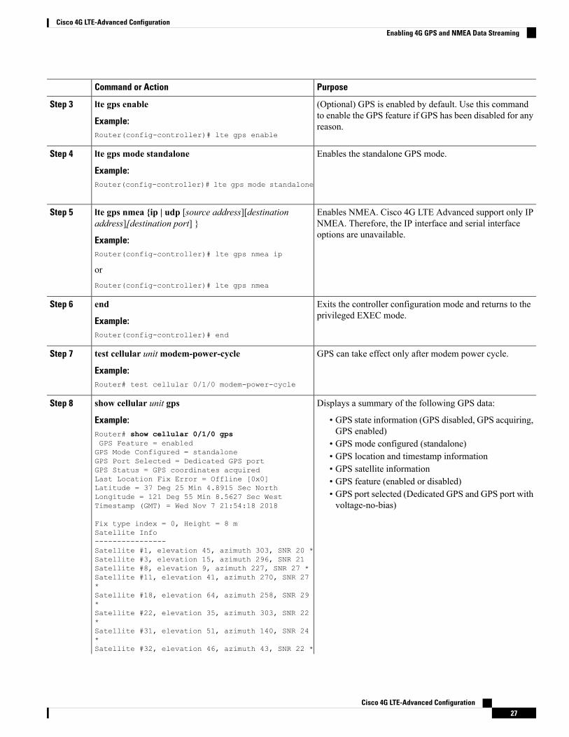
(Optional) GPS is enabled by default. Use this commandto enable the GPS feature if GPS has been disabled for anyreason.
lte gps enable
Example:Router(config-controller)# lte gps enable
Step 3
Enables the standalone GPS mode.lte gps mode standalone
Example:
Step 4
Router(config-controller)# lte gps mode standalone
Enables NMEA. Cisco 4G LTE Advanced support only IPNMEA. Therefore, the IP interface and serial interfaceoptions are unavailable.
lte gps nmea {ip | udp [source address][destinationaddress][destination port] }
Example:
Step 5
Router(config-controller)# lte gps nmea ip
orRouter(config-controller)# lte gps nmea
Exits the controller configuration mode and returns to theprivileged EXEC mode.
end
Example:
Step 6
Router(config-controller)# end
GPS can take effect only after modem power cycle.test cellular unitmodem-power-cycle
Example:
Step 7
Router# test cellular 0/1/0 modem-power-cycle
Displays a summary of the following GPS data:show cellular unit gpsStep 8
Example: • GPS state information (GPS disabled, GPS acquiring,GPS enabled)Router# show cellular 0/1/0 gps
GPS Feature = enabled • GPS mode configured (standalone)GPS Mode Configured = standalone • GPS location and timestamp informationGPS Port Selected = Dedicated GPS port
• GPS satellite informationGPS Status = GPS coordinates acquiredLast Location Fix Error = Offline [0x0] • GPS feature (enabled or disabled)Latitude = 37 Deg 25 Min 4.8915 Sec North
• GPS port selected (Dedicated GPS and GPS port withvoltage-no-bias)
Longitude = 121 Deg 55 Min 8.5627 Sec WestTimestamp (GMT) = Wed Nov 7 21:54:18 2018
Fix type index = 0, Height = 8 mSatellite Info----------------Satellite #1, elevation 45, azimuth 303, SNR 20 *Satellite #3, elevation 15, azimuth 296, SNR 21Satellite #8, elevation 9, azimuth 227, SNR 27 *Satellite #11, elevation 41, azimuth 270, SNR 27*Satellite #18, elevation 64, azimuth 258, SNR 29*Satellite #22, elevation 35, azimuth 303, SNR 22*Satellite #31, elevation 51, azimuth 140, SNR 24*Satellite #32, elevation 46, azimuth 43, SNR 22 *
Cisco 4G LTE-Advanced Configuration27
Cisco 4G LTE-Advanced ConfigurationEnabling 4G GPS and NMEA Data Streaming
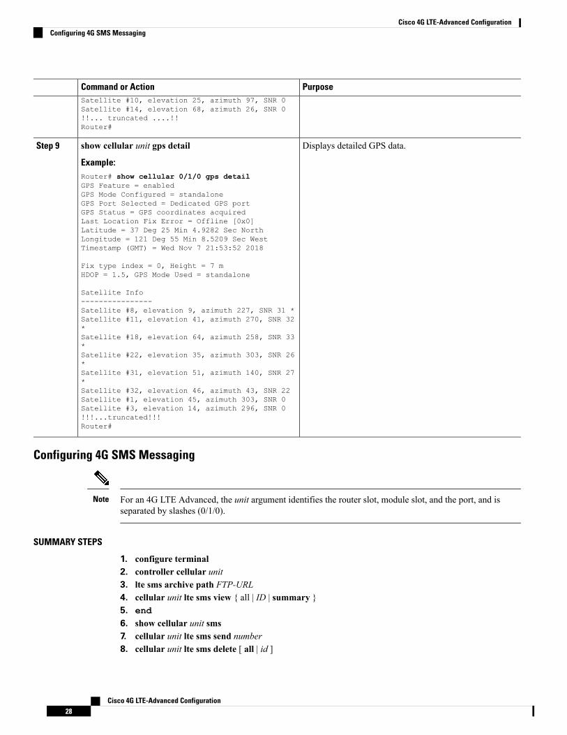
PurposeCommand or ActionSatellite #10, elevation 25, azimuth 97, SNR 0Satellite #14, elevation 68, azimuth 26, SNR 0!!... truncated ....!!Router#
Displays detailed GPS data.show cellular unit gps detail
Example:
Step 9
Router# show cellular 0/1/0 gps detailGPS Feature = enabledGPS Mode Configured = standaloneGPS Port Selected = Dedicated GPS portGPS Status = GPS coordinates acquiredLast Location Fix Error = Offline [0x0]Latitude = 37 Deg 25 Min 4.9282 Sec NorthLongitude = 121 Deg 55 Min 8.5209 Sec WestTimestamp (GMT) = Wed Nov 7 21:53:52 2018
Fix type index = 0, Height = 7 mHDOP = 1.5, GPS Mode Used = standalone
Satellite Info----------------Satellite #8, elevation 9, azimuth 227, SNR 31 *Satellite #11, elevation 41, azimuth 270, SNR 32*Satellite #18, elevation 64, azimuth 258, SNR 33*Satellite #22, elevation 35, azimuth 303, SNR 26*Satellite #31, elevation 51, azimuth 140, SNR 27*Satellite #32, elevation 46, azimuth 43, SNR 22Satellite #1, elevation 45, azimuth 303, SNR 0Satellite #3, elevation 14, azimuth 296, SNR 0!!!...truncated!!!Router#
Configuring 4G SMS Messaging
For an 4G LTE Advanced, the unit argument identifies the router slot, module slot, and the port, and isseparated by slashes (0/1/0).
Note
SUMMARY STEPS
1. configure terminal2. controller cellular unit3. lte sms archive path FTP-URL4. cellular unit lte sms view { all | ID | summary }5. end6. show cellular unit sms7. cellular unit lte sms send number8. cellular unit lte sms delete [ all | id ]
Cisco 4G LTE-Advanced Configuration28
Cisco 4G LTE-Advanced ConfigurationConfiguring 4G SMS Messaging
DETAILED STEPS
PurposeCommand or Action
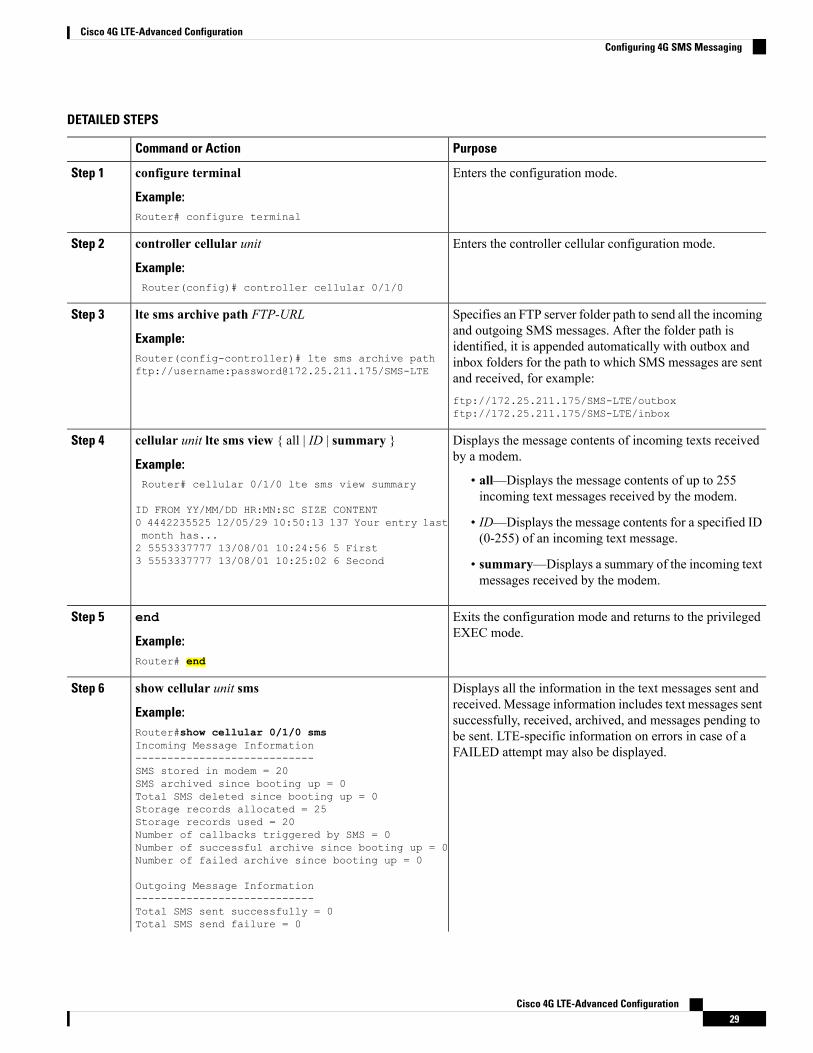
Enters the configuration mode.configure terminal
Example:
Step 1
Router# configure terminal
Enters the controller cellular configuration mode.controller cellular unit
Example:
Step 2
Router(config)# controller cellular 0/1/0
Specifies an FTP server folder path to send all the incomingand outgoing SMS messages. After the folder path is
lte sms archive path FTP-URL
Example:
Step 3
identified, it is appended automatically with outbox andRouter(config-controller)# lte sms archive pathftp://username:[email protected]/SMS-LTE
inbox folders for the path to which SMS messages are sentand received, for example:ftp://172.25.211.175/SMS-LTE/outboxftp://172.25.211.175/SMS-LTE/inbox
Displays the message contents of incoming texts receivedby a modem.
cellular unit lte sms view { all | ID | summary }
Example:
Step 4
• all—Displays the message contents of up to 255incoming text messages received by the modem.
Router# cellular 0/1/0 lte sms view summary
ID FROM YY/MM/DD HR:MN:SC SIZE CONTENT• ID—Displays the message contents for a specified ID(0-255) of an incoming text message.
0 4442235525 12/05/29 10:50:13 137 Your entry lastmonth has...2 5553337777 13/08/01 10:24:56 5 First3 5553337777 13/08/01 10:25:02 6 Second • summary—Displays a summary of the incoming text
messages received by the modem.
Exits the configuration mode and returns to the privilegedEXEC mode.
end
Example:
Step 5
Router# end
Displays all the information in the text messages sent andreceived. Message information includes text messages sent
show cellular unit sms
Example:
Step 6
successfully, received, archived, and messages pending toRouter#show cellular 0/1/0 smsIncoming Message Information
be sent. LTE-specific information on errors in case of aFAILED attempt may also be displayed.----------------------------
SMS stored in modem = 20SMS archived since booting up = 0Total SMS deleted since booting up = 0Storage records allocated = 25Storage records used = 20Number of callbacks triggered by SMS = 0Number of successful archive since booting up = 0Number of failed archive since booting up = 0
Outgoing Message Information----------------------------Total SMS sent successfully = 0Total SMS send failure = 0
Cisco 4G LTE-Advanced Configuration29
Cisco 4G LTE-Advanced ConfigurationConfiguring 4G SMS Messaging
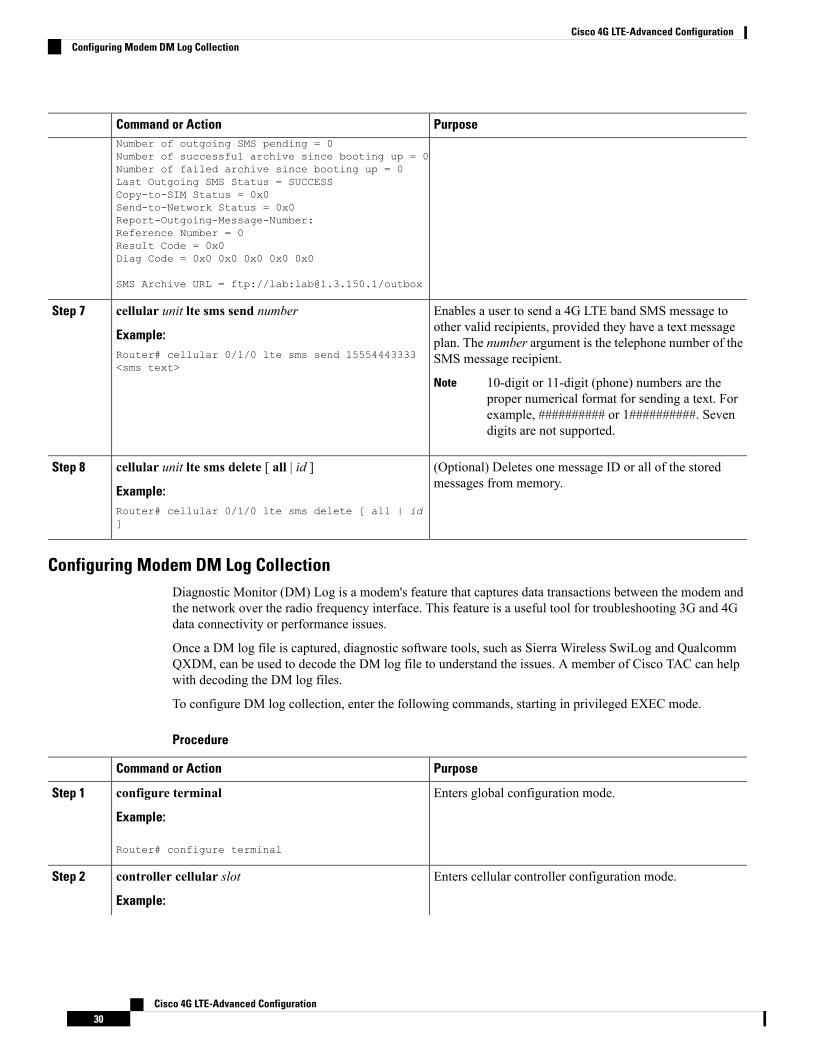
PurposeCommand or ActionNumber of outgoing SMS pending = 0Number of successful archive since booting up = 0Number of failed archive since booting up = 0Last Outgoing SMS Status = SUCCESSCopy-to-SIM Status = 0x0Send-to-Network Status = 0x0Report-Outgoing-Message-Number:Reference Number = 0Result Code = 0x0Diag Code = 0x0 0x0 0x0 0x0 0x0
SMS Archive URL = ftp://lab:[email protected]/outbox
Enables a user to send a 4G LTE band SMS message toother valid recipients, provided they have a text message
cellular unit lte sms send number
Example:
Step 7
plan. The number argument is the telephone number of theSMS message recipient.Router# cellular 0/1/0 lte sms send 15554443333
<sms text>
10-digit or 11-digit (phone) numbers are theproper numerical format for sending a text. Forexample, ########## or 1##########. Sevendigits are not supported.
Note
(Optional) Deletes one message ID or all of the storedmessages from memory.
cellular unit lte sms delete [ all | id ]
Example:
Step 8
Router# cellular 0/1/0 lte sms delete [ all | id]
Configuring Modem DM Log CollectionDiagnostic Monitor (DM) Log is a modem's feature that captures data transactions between the modem andthe network over the radio frequency interface. This feature is a useful tool for troubleshooting 3G and 4Gdata connectivity or performance issues.
Once a DM log file is captured, diagnostic software tools, such as Sierra Wireless SwiLog and QualcommQXDM, can be used to decode the DM log file to understand the issues. A member of Cisco TAC can helpwith decoding the DM log files.
To configure DM log collection, enter the following commands, starting in privileged EXEC mode.
Procedure
PurposeCommand or Action
Enters global configuration mode.configure terminal
Example:
Step 1
Router# configure terminal
Enters cellular controller configuration mode.controller cellular slot
Example:
Step 2
Cisco 4G LTE-Advanced Configuration30
Cisco 4G LTE-Advanced ConfigurationConfiguring Modem DM Log Collection
PurposeCommand or Action
Router(config)# controller cellular 0/1/0
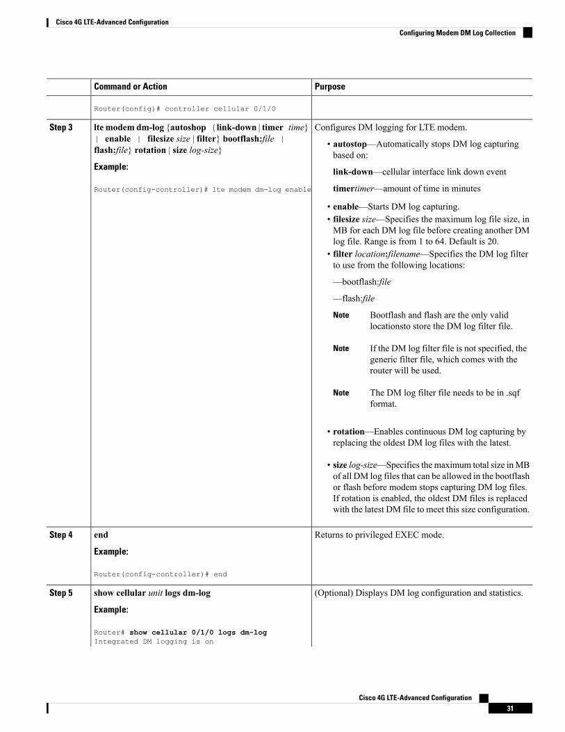
Configures DM logging for LTE modem.lte modemdm-log {autoshop {link-down | timer time}| enable | filesize size | filter} bootflash:file |flash:file} rotation | size log-size}
Step 3
• autostop—Automatically stops DM log capturingbased on:
link-down—cellular interface link down eventExample:
Router(config-controller)# lte modem dm-log enable timertimer—amount of time in minutes
• enable—Starts DM log capturing.• filesize size—Specifies the maximum log file size, inMB for each DM log file before creating another DMlog file. Range is from 1 to 64. Default is 20.
• filter location:filename—Specifies the DM log filterto use from the following locations:
—bootflash:file
—flash:file
Bootflash and flash are the only validlocationsto store the DM log filter file.
Note
If the DM log filter file is not specified, thegeneric filter file, which comes with therouter will be used.
Note
The DM log filter file needs to be in .sqfformat.
Note
• rotation—Enables continuous DM log capturing byreplacing the oldest DM log files with the latest.
• size log-size—Specifies the maximum total size inMBof all DM log files that can be allowed in the bootflashor flash before modem stops capturing DM log files.If rotation is enabled, the oldest DM files is replacedwith the latest DM file to meet this size configuration.
Returns to privileged EXEC mode.end
Example:
Step 4
Router(config-controller)# end
(Optional) Displays DM log configuration and statistics.show cellular unit logs dm-log
Example:
Step 5
Router# show cellular 0/1/0 logs dm-logIntegrated DM logging is on
Cisco 4G LTE-Advanced Configuration31
Cisco 4G LTE-Advanced ConfigurationConfiguring Modem DM Log Collection
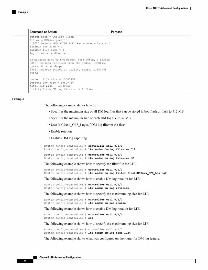
PurposeCommand or Actionoutput path = Utility Flashfilter = MC74xx generic -v11026_Generic_GSM_WCDMA_LTE_IP-no-data-packets.sqfmaximum log size = 0maximum file size = 0log rotation = disabled
33 packets sent to the modem, 4663 bytes, 0 errors28521 packets received from the modem, 13500758bytes, 0 input drops28521 packets stored in utility flash, 13500758bytes
current file size = 13500758current log size = 13500758total log size = 13500758Utility Flash DM log files = (1) files
Example
The following example shows how to:
• Specifies the maximum size of all DM log files that can be stored in bootflash or flash to 512 MB
• Specifies the maximum size of each DM log file to 32 MB
• Uses MC7xxx_GPS_Log.sqf DM log filter in the flash
• Enable rotation
• Enables DM log capturing
Router(config-controller)# controller cell 0/1/0Router(config-controller)# lte modem dm-log filesize 512
Router(config-controller)# controller cell 0/1/0Router(config-controller)# lte modem dm-log filesize 32
The following example shows how to specify the filter file for LTE:Router(config-controller)# controller cell 0/1/0Router(config-controller)# lte modem dm-log filter flash:MC7xxx_GPS_Log.sqf
The following example shows how to enable DM log rotation for LTE:Router(config-controller)# controller cell 0/1/0Router(config-controller)# lte modem dm-log rotation
The following example shows how to specify the maximum log size for LTE:Router(config-controller)# controller cell 0/1/0Router(config-controller)# lte modem dm-log enable
The following example shows how to enable DM log rotation for LTE:Router(config-controller)# controller cell 0/1/0Router(config-controller)# end
The following example shows how to specify the maximum log size for LTE:Router(config-controller)# controller cell 0/1/0Router(config-controller)# lte modem dm-log size 1024
The following example shows what was configured on the router for DM log feature:
Cisco 4G LTE-Advanced Configuration32
Cisco 4G LTE-Advanced ConfigurationExample

Router#show running-config | section controllercontroller Cellular 0/1/0lte modem dm-log filter flash:MC7xxx_GPS_Log.sqflte modem dm-log size 512lte modem dm-log filesize 32lte modem dm-log rotationlte modem dm-log enablelte modem dm-log size 1024
The following displays DM log configuration and statisticsRouter#show cellular 0/1/0 logs dm-logIntegrated DM logging is onoutput path = Utility Flashfilter = flash:MC7xxx_GPS_Log.sqfmaximum log size = 536870912maximum file size = 33554432log rotation = enabled
32 packets sent to the modem, 3879 bytes, 0 errors158324 packets received from the modem, 75971279 bytes, 0 input drops158324 packets stored in utility flash, 75971279 bytes
current file size = 8863042current log size = 75971279total log size = 75971279Utility Flash DM log files = (3) filesend
The following shows the DM log files created:Router#dir flash:dmlog*Directory of bootflash:/dmlog*
Directory of bootflash:/
27 -rw- 33554069 Jun 7 2018 18:08:46 -08:00 dmlog-slot2-20180607-180628.bin28 -rw- 33554168 Jun 7 2018 18:11:25 -08:00 dmlog-slot2-20180607-180846.bin29 -rw- 14188544 Jun 7 2018 18:12:37 -08:00 dmlog-slot2-20180607-181125.bin
2885718016 bytes total (521891840 bytes free)lte modem dm-log size 1024
The following shows hot to disable/stop DM log capturing:Router(config)#controller cellular 0/1/0Router(config-controller)#no lte modem dm-log enableRouter(config-controller)#end
Enabling Modem Crashdump CollectionModem crashdump collection is useful in debugging firmware crash. To collect crash data, the modem hasto be pre-configured so that it will stay in memdump mode after a crash. Memdump mode is a specialboot-and-hold mode for the memdump utility to collect crash data.
To enable modem crashdump collection, perform the following steps.
The integrated modem crashdump collection feature is supported only on 3G HSPA and 4G LTE Advancedbased SKUs.
Note
Cisco 4G LTE-Advanced Configuration33
Cisco 4G LTE-Advanced ConfigurationEnabling Modem Crashdump Collection
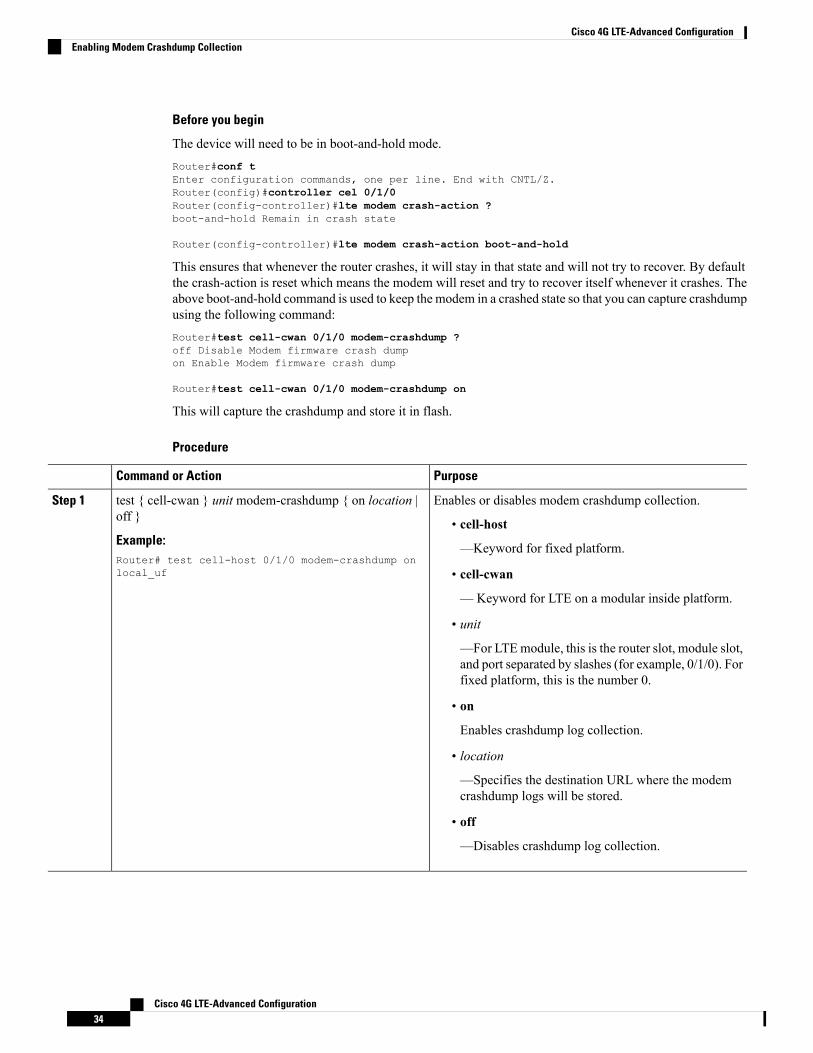
Before you begin
The device will need to be in boot-and-hold mode.Router#conf tEnter configuration commands, one per line. End with CNTL/Z.Router(config)#controller cel 0/1/0Router(config-controller)#lte modem crash-action ?boot-and-hold Remain in crash state
Router(config-controller)#lte modem crash-action boot-and-hold
This ensures that whenever the router crashes, it will stay in that state and will not try to recover. By defaultthe crash-action is reset which means the modem will reset and try to recover itself whenever it crashes. Theabove boot-and-hold command is used to keep the modem in a crashed state so that you can capture crashdumpusing the following command:Router#test cell-cwan 0/1/0 modem-crashdump ?off Disable Modem firmware crash dumpon Enable Modem firmware crash dump
Router#test cell-cwan 0/1/0 modem-crashdump on
This will capture the crashdump and store it in flash.
Procedure
PurposeCommand or Action
Enables or disables modem crashdump collection.test { cell-cwan } unit modem-crashdump { on location |off }
Step 1
• cell-host
—Keyword for fixed platform.Example:Router# test cell-host 0/1/0 modem-crashdump onlocal_uf • cell-cwan
—Keyword for LTE on a modular inside platform.
• unit
—For LTEmodule, this is the router slot, module slot,and port separated by slashes (for example, 0/1/0). Forfixed platform, this is the number 0.
• on
Enables crashdump log collection.
• location
—Specifies the destination URL where the modemcrashdump logs will be stored.
• off
—Disables crashdump log collection.
Cisco 4G LTE-Advanced Configuration34
Cisco 4G LTE-Advanced ConfigurationEnabling Modem Crashdump Collection
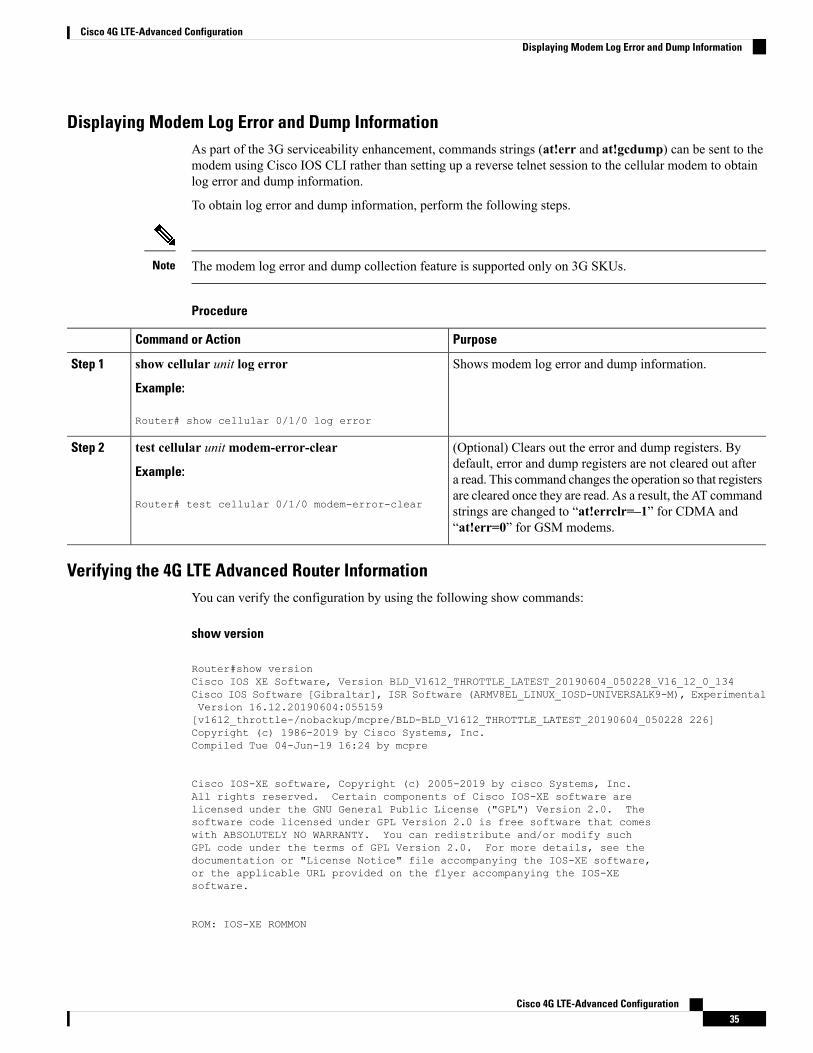
Displaying Modem Log Error and Dump InformationAs part of the 3G serviceability enhancement, commands strings (at!err and at!gcdump) can be sent to themodem using Cisco IOS CLI rather than setting up a reverse telnet session to the cellular modem to obtainlog error and dump information.
To obtain log error and dump information, perform the following steps.
The modem log error and dump collection feature is supported only on 3G SKUs.Note
Procedure
PurposeCommand or Action
Shows modem log error and dump information.show cellular unit log error
Example:
Step 1
Router# show cellular 0/1/0 log error
(Optional) Clears out the error and dump registers. Bydefault, error and dump registers are not cleared out after
test cellular unitmodem-error-clear
Example:
Step 2
a read. This command changes the operation so that registers
Router# test cellular 0/1/0 modem-error-clearare cleared once they are read. As a result, the AT commandstrings are changed to “at!errclr=–1” for CDMA and“at!err=0” for GSM modems.
Verifying the 4G LTE Advanced Router InformationYou can verify the configuration by using the following show commands:
show version
Router#show versionCisco IOS XE Software, Version BLD_V1612_THROTTLE_LATEST_20190604_050228_V16_12_0_134Cisco IOS Software [Gibraltar], ISR Software (ARMV8EL_LINUX_IOSD-UNIVERSALK9-M), ExperimentalVersion 16.12.20190604:055159[v1612_throttle-/nobackup/mcpre/BLD-BLD_V1612_THROTTLE_LATEST_20190604_050228 226]Copyright (c) 1986-2019 by Cisco Systems, Inc.Compiled Tue 04-Jun-19 16:24 by mcpre
Cisco IOS-XE software, Copyright (c) 2005-2019 by cisco Systems, Inc.All rights reserved. Certain components of Cisco IOS-XE software arelicensed under the GNU General Public License ("GPL") Version 2.0. Thesoftware code licensed under GPL Version 2.0 is free software that comeswith ABSOLUTELY NO WARRANTY. You can redistribute and/or modify suchGPL code under the terms of GPL Version 2.0. For more details, see thedocumentation or "License Notice" file accompanying the IOS-XE software,or the applicable URL provided on the flyer accompanying the IOS-XEsoftware.
ROM: IOS-XE ROMMON
Cisco 4G LTE-Advanced Configuration35
Cisco 4G LTE-Advanced ConfigurationDisplaying Modem Log Error and Dump Information
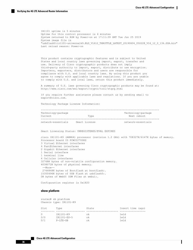
IR1101 uptime is 5 minutesUptime for this control processor is 6 minutesSystem returned to ROM by Power-on at 17:11:39 GMT Tue Jun 25 2019System image file is"usbflash0:ir1101-universalk9.BLD_V1612_THROTTLE_LATEST_20190604_050228_V16_12_0_134.SSA.bin"Last reload reason: Power-on
This product contains cryptographic features and is subject to UnitedStates and local country laws governing import, export, transfer anduse. Delivery of Cisco cryptographic products does not implythird-party authority to import, export, distribute or use encryption.Importers, exporters, distributors and users are responsible forcompliance with U.S. and local country laws. By using this product youagree to comply with applicable laws and regulations. If you are unableto comply with U.S. and local laws, return this product immediately.
A summary of U.S. laws governing Cisco cryptographic products may be found at:http://www.cisco.com/wwl/export/crypto/tool/stqrg.html
If you require further assistance please contact us by sending email [email protected].
Technology Package License Information:
------------------------------------------------------------------------------Technology-package Technology-packageCurrent Type Next reboot------------------------------------------------------------------------------network-essentials Smart License network-essentials
Smart Licensing Status: UNREGISTERED/EVAL EXPIRED
cisco IR1101-K9 (ARM64) processor (revision 1.2 GHz) with 708327K/6147K bytes of memory.Processor board ID FCW222700KS3 Virtual Ethernet interfaces4 FastEthernet interfaces2 Gigabit Ethernet interfaces1 Serial interface1 terminal line4 Cellular interfaces32768K bytes of non-volatile configuration memory.4038072K bytes of physical memory.--More--2766848K bytes of Bootflash at bootflash:.15350496K bytes of USB Flash at usbflash0:.0K bytes of WebUI ODM Files at webui:.
Configuration register is 0x1820
show platform
router# sh platformChassis type: IR1101-K9
Slot Type State Insert time (ago)--------- ------------------- --------------------- -----------------0 IR1101-K9 ok 1w1d0/0 IR1101-ES-5 ok 1w1d0/1 P-LTE-GB ok 1w1d
Cisco 4G LTE-Advanced Configuration36
Cisco 4G LTE-Advanced ConfigurationVerifying the 4G LTE Advanced Router Information
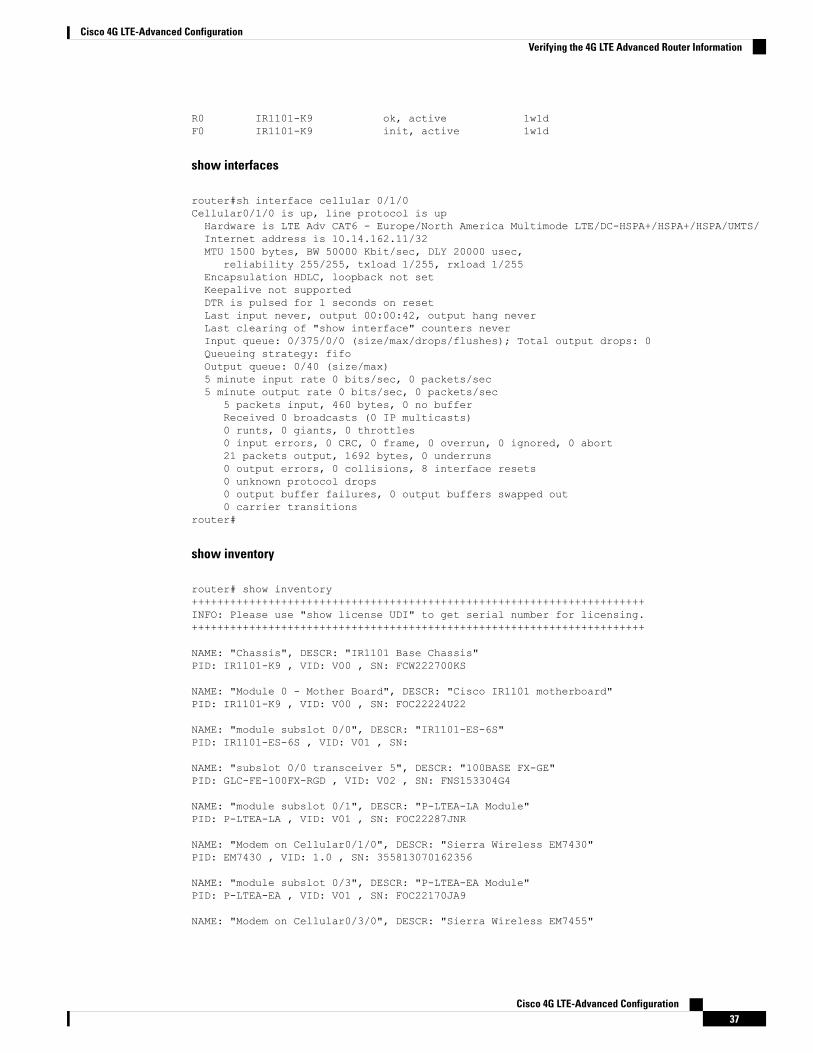
R0 IR1101-K9 ok, active 1w1dF0 IR1101-K9 init, active 1w1d
show interfaces
router#sh interface cellular 0/1/0Cellular0/1/0 is up, line protocol is upHardware is LTE Adv CAT6 - Europe/North America Multimode LTE/DC-HSPA+/HSPA+/HSPA/UMTS/Internet address is 10.14.162.11/32MTU 1500 bytes, BW 50000 Kbit/sec, DLY 20000 usec,
reliability 255/255, txload 1/255, rxload 1/255Encapsulation HDLC, loopback not setKeepalive not supportedDTR is pulsed for 1 seconds on resetLast input never, output 00:00:42, output hang neverLast clearing of "show interface" counters neverInput queue: 0/375/0/0 (size/max/drops/flushes); Total output drops: 0Queueing strategy: fifoOutput queue: 0/40 (size/max)5 minute input rate 0 bits/sec, 0 packets/sec5 minute output rate 0 bits/sec, 0 packets/sec
5 packets input, 460 bytes, 0 no bufferReceived 0 broadcasts (0 IP multicasts)0 runts, 0 giants, 0 throttles0 input errors, 0 CRC, 0 frame, 0 overrun, 0 ignored, 0 abort21 packets output, 1692 bytes, 0 underruns0 output errors, 0 collisions, 8 interface resets0 unknown protocol drops0 output buffer failures, 0 output buffers swapped out0 carrier transitions
router#
show inventory
router# show inventory+++++++++++++++++++++++++++++++++++++++++++++++++++++++++++++++++++++++INFO: Please use "show license UDI" to get serial number for licensing.+++++++++++++++++++++++++++++++++++++++++++++++++++++++++++++++++++++++
NAME: "Chassis", DESCR: "IR1101 Base Chassis"PID: IR1101-K9 , VID: V00 , SN: FCW222700KS
NAME: "Module 0 - Mother Board", DESCR: "Cisco IR1101 motherboard"PID: IR1101-K9 , VID: V00 , SN: FOC22224U22
NAME: "module subslot 0/0", DESCR: "IR1101-ES-6S"PID: IR1101-ES-6S , VID: V01 , SN:
NAME: "subslot 0/0 transceiver 5", DESCR: "100BASE FX-GE"PID: GLC-FE-100FX-RGD , VID: V02 , SN: FNS153304G4
NAME: "module subslot 0/1", DESCR: "P-LTEA-LA Module"PID: P-LTEA-LA , VID: V01 , SN: FOC22287JNR
NAME: "Modem on Cellular0/1/0", DESCR: "Sierra Wireless EM7430"PID: EM7430 , VID: 1.0 , SN: 355813070162356
NAME: "module subslot 0/3", DESCR: "P-LTEA-EA Module"PID: P-LTEA-EA , VID: V01 , SN: FOC22170JA9
NAME: "Modem on Cellular0/3/0", DESCR: "Sierra Wireless EM7455"
Cisco 4G LTE-Advanced Configuration37
Cisco 4G LTE-Advanced ConfigurationVerifying the 4G LTE Advanced Router Information
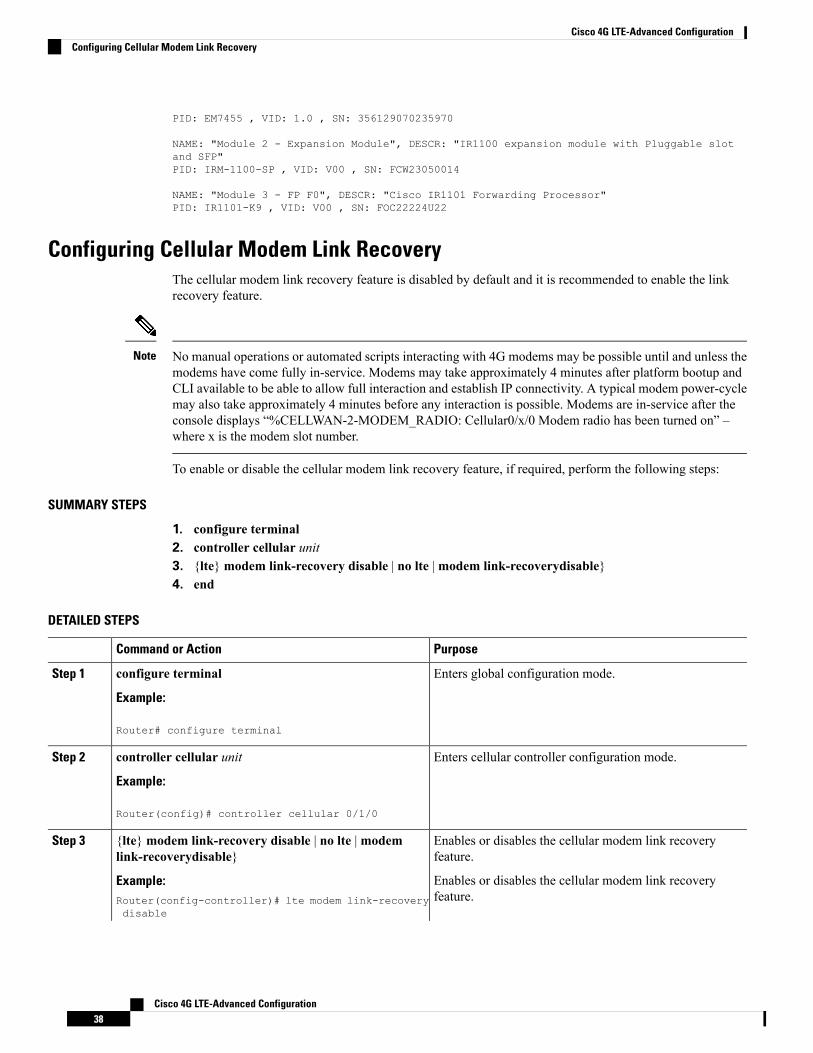
PID: EM7455 , VID: 1.0 , SN: 356129070235970
NAME: "Module 2 - Expansion Module", DESCR: "IR1100 expansion module with Pluggable slotand SFP"PID: IRM-1100-SP , VID: V00 , SN: FCW23050014
NAME: "Module 3 - FP F0", DESCR: "Cisco IR1101 Forwarding Processor"PID: IR1101-K9 , VID: V00 , SN: FOC22224U22
Configuring Cellular Modem Link RecoveryThe cellular modem link recovery feature is disabled by default and it is recommended to enable the linkrecovery feature.
No manual operations or automated scripts interacting with 4G modems may be possible until and unless themodems have come fully in-service. Modems may take approximately 4 minutes after platform bootup andCLI available to be able to allow full interaction and establish IP connectivity. A typical modem power-cyclemay also take approximately 4 minutes before any interaction is possible. Modems are in-service after theconsole displays “%CELLWAN-2-MODEM_RADIO: Cellular0/x/0 Modem radio has been turned on” –where x is the modem slot number.
Note
To enable or disable the cellular modem link recovery feature, if required, perform the following steps:
SUMMARY STEPS
1. configure terminal2. controller cellular unit3. {lte}modem link-recovery disable | no lte |modem link-recoverydisable}4. end
DETAILED STEPS
PurposeCommand or Action
Enters global configuration mode.configure terminal
Example:
Step 1
Router# configure terminal
Enters cellular controller configuration mode.controller cellular unit
Example:
Step 2
Router(config)# controller cellular 0/1/0
Enables or disables the cellular modem link recoveryfeature.
{lte}modem link-recovery disable | no lte |modemlink-recoverydisable}
Step 3
Example: Enables or disables the cellular modem link recoveryfeature.Router(config-controller)# lte modem link-recovery
disable
Cisco 4G LTE-Advanced Configuration38
Cisco 4G LTE-Advanced ConfigurationConfiguring Cellular Modem Link Recovery
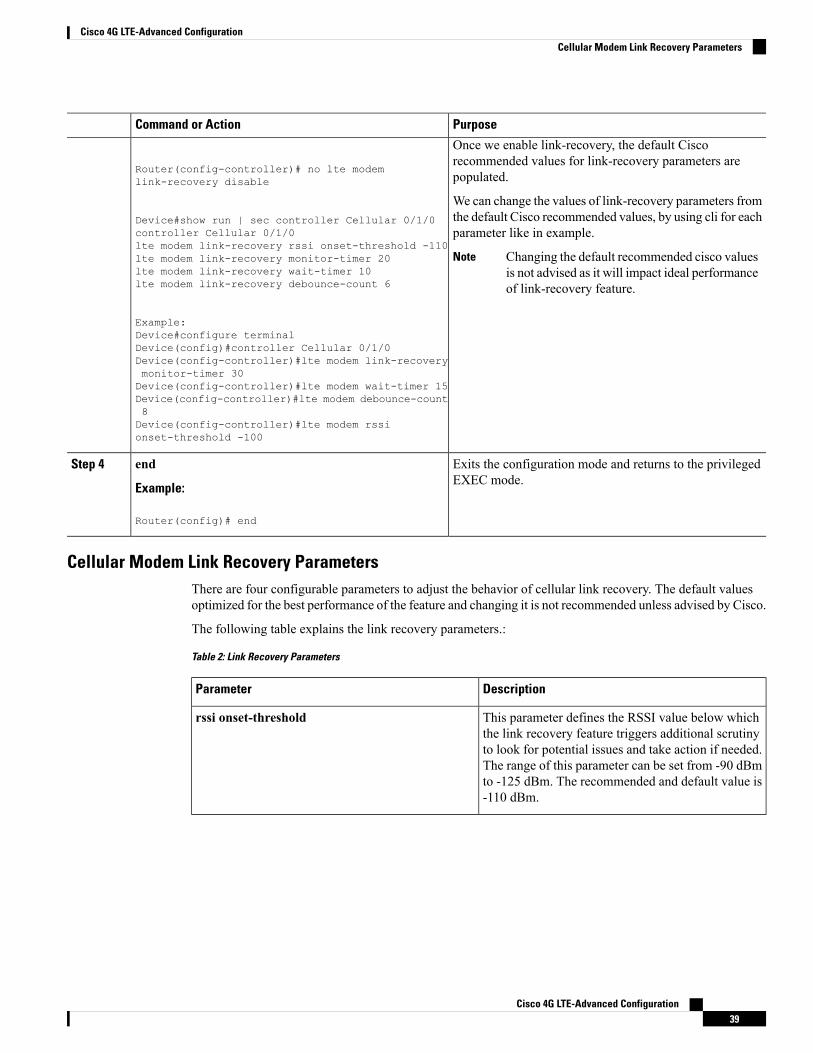
PurposeCommand or Action
Once we enable link-recovery, the default Ciscorecommended values for link-recovery parameters arepopulated.
Router(config-controller)# no lte modemlink-recovery disable
We can change the values of link-recovery parameters fromthe default Cisco recommended values, by using cli for eachparameter like in example.
Device#show run | sec controller Cellular 0/1/0controller Cellular 0/1/0lte modem link-recovery rssi onset-threshold -110
Changing the default recommended cisco valuesis not advised as it will impact ideal performanceof link-recovery feature.
Notelte modem link-recovery monitor-timer 20lte modem link-recovery wait-timer 10lte modem link-recovery debounce-count 6
Example:Device#configure terminalDevice(config)#controller Cellular 0/1/0Device(config-controller)#lte modem link-recoverymonitor-timer 30Device(config-controller)#lte modem wait-timer 15Device(config-controller)#lte modem debounce-count8Device(config-controller)#lte modem rssionset-threshold -100
Exits the configuration mode and returns to the privilegedEXEC mode.
end
Example:
Step 4
Router(config)# end
Cellular Modem Link Recovery ParametersThere are four configurable parameters to adjust the behavior of cellular link recovery. The default valuesoptimized for the best performance of the feature and changing it is not recommended unless advised by Cisco.
The following table explains the link recovery parameters.:
Table 2: Link Recovery Parameters
DescriptionParameter
This parameter defines the RSSI value below whichthe link recovery feature triggers additional scrutinyto look for potential issues and take action if needed.The range of this parameter can be set from -90 dBmto -125 dBm. The recommended and default value is-110 dBm.
rssi onset-threshold
Cisco 4G LTE-Advanced Configuration39
Cisco 4G LTE-Advanced ConfigurationCellular Modem Link Recovery Parameters
DescriptionParameter
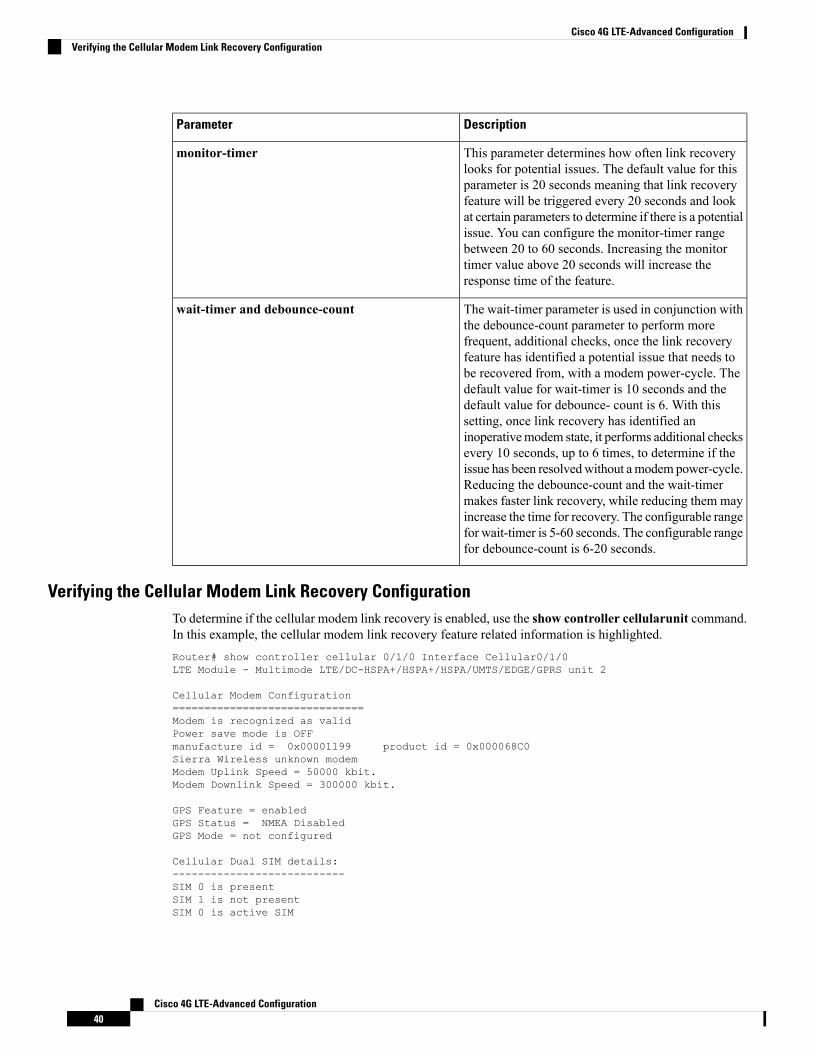
This parameter determines how often link recoverylooks for potential issues. The default value for thisparameter is 20 seconds meaning that link recoveryfeature will be triggered every 20 seconds and lookat certain parameters to determine if there is a potentialissue. You can configure the monitor-timer rangebetween 20 to 60 seconds. Increasing the monitortimer value above 20 seconds will increase theresponse time of the feature.
monitor-timer
The wait-timer parameter is used in conjunction withthe debounce-count parameter to perform morefrequent, additional checks, once the link recoveryfeature has identified a potential issue that needs tobe recovered from, with a modem power-cycle. Thedefault value for wait-timer is 10 seconds and thedefault value for debounce- count is 6. With thissetting, once link recovery has identified aninoperativemodem state, it performs additional checksevery 10 seconds, up to 6 times, to determine if theissue has been resolvedwithout amodem power-cycle.Reducing the debounce-count and the wait-timermakes faster link recovery, while reducing them mayincrease the time for recovery. The configurable rangefor wait-timer is 5-60 seconds. The configurable rangefor debounce-count is 6-20 seconds.
wait-timer and debounce-count
Verifying the Cellular Modem Link Recovery ConfigurationTo determine if the cellular modem link recovery is enabled, use the show controller cellularunit command.In this example, the cellular modem link recovery feature related information is highlighted.Router# show controller cellular 0/1/0 Interface Cellular0/1/0LTE Module - Multimode LTE/DC-HSPA+/HSPA+/HSPA/UMTS/EDGE/GPRS unit 2
Cellular Modem Configuration==============================Modem is recognized as validPower save mode is OFFmanufacture id = 0x00001199 product id = 0x000068C0Sierra Wireless unknown modemModem Uplink Speed = 50000 kbit.Modem Downlink Speed = 300000 kbit.
GPS Feature = enabledGPS Status = NMEA DisabledGPS Mode = not configured
Cellular Dual SIM details:---------------------------SIM 0 is presentSIM 1 is not presentSIM 0 is active SIM
Cisco 4G LTE-Advanced Configuration40
Cisco 4G LTE-Advanced ConfigurationVerifying the Cellular Modem Link Recovery Configuration
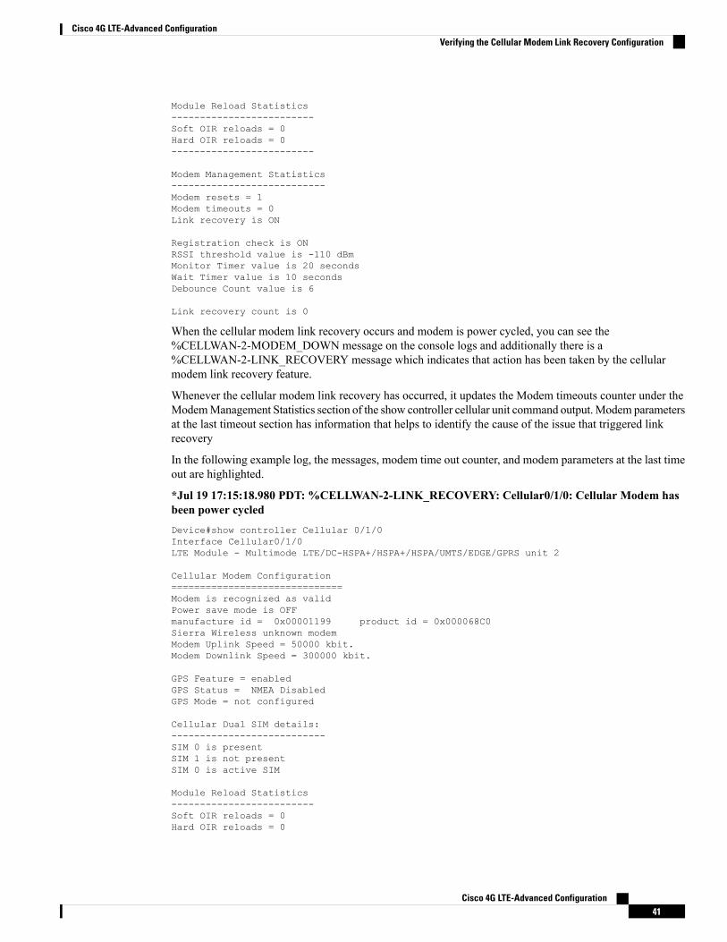
Module Reload Statistics-------------------------Soft OIR reloads = 0Hard OIR reloads = 0-------------------------
Modem Management Statistics---------------------------Modem resets = 1Modem timeouts = 0Link recovery is ON
Registration check is ONRSSI threshold value is -110 dBmMonitor Timer value is 20 secondsWait Timer value is 10 secondsDebounce Count value is 6
Link recovery count is 0
When the cellular modem link recovery occurs and modem is power cycled, you can see the%CELLWAN-2-MODEM_DOWN message on the console logs and additionally there is a%CELLWAN-2-LINK_RECOVERY message which indicates that action has been taken by the cellularmodem link recovery feature.
Whenever the cellular modem link recovery has occurred, it updates the Modem timeouts counter under theModemManagement Statistics section of the show controller cellular unit command output.Modem parametersat the last timeout section has information that helps to identify the cause of the issue that triggered linkrecovery
In the following example log, the messages, modem time out counter, and modem parameters at the last timeout are highlighted.
*Jul 19 17:15:18.980 PDT: %CELLWAN-2-LINK_RECOVERY: Cellular0/1/0: Cellular Modem hasbeen power cycledDevice#show controller Cellular 0/1/0Interface Cellular0/1/0LTE Module - Multimode LTE/DC-HSPA+/HSPA+/HSPA/UMTS/EDGE/GPRS unit 2
Cellular Modem Configuration==============================Modem is recognized as validPower save mode is OFFmanufacture id = 0x00001199 product id = 0x000068C0Sierra Wireless unknown modemModem Uplink Speed = 50000 kbit.Modem Downlink Speed = 300000 kbit.
GPS Feature = enabledGPS Status = NMEA DisabledGPS Mode = not configured
Cellular Dual SIM details:---------------------------SIM 0 is presentSIM 1 is not presentSIM 0 is active SIM
Module Reload Statistics-------------------------Soft OIR reloads = 0Hard OIR reloads = 0
Cisco 4G LTE-Advanced Configuration41
Cisco 4G LTE-Advanced ConfigurationVerifying the Cellular Modem Link Recovery Configuration
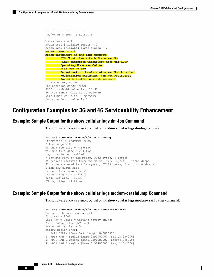
-------------------------Modem Management Statistics---------------------------Modem resets = 1Modem user initiated resets = 0Modem user initiated power-cycles = 0Modem timeouts = 1Modem parameters at the last timeout:
LTE first time attach State was NoRadio Interface Technology Mode was AUTOOperating Mode was OnlineRSSI was -0 dBmPacket switch domain status was Not AttachedRegistration state(EMM) was Not RegisteredDownlink traffic was not present
Link recovery is ONRegistration check is ONRSSI threshold value is -110 dBmMonitor Timer value is 20 secondsWait Timer value is 10 secondsDebounce Count value is 6
Configuration Examples for 3G and 4G Serviceability Enhancement
Example: Sample Output for the show cellular logs dm-log CommandThe following shows a sample output of the show cellular logs dm-log command:
Router# show cellular 0/1/0 logs dm-logIntegrated DM logging is onfilter = genericmaximum log size = 67108864maximum file size = 20971520log rotation = disabled7 packets sent to the modem, 3232 bytes, 0 errors75 packets received from the modem, 57123 bytes, 0 input drops75 packets stored in file system, 57123 bytes, 0 errors, 0 aborts2 max rcv queue sizecurrent file size = 57123current log size = 57123total log size = 57123DM log files: (1 files)
Example: Sample Output for the show cellular logs modem-crashdump CommandThe following shows a sample output of the show cellular logs modem-crashdump command:
Router# show cellular 0/1/0 logs modem-crashdumpModem crashdump logging: offProgress = 100%Last known State = Getting memory chunksTotal consecutive NAKs = 0Number of retries = 0Memory Region Info:1: Full SDRAM [Base:0x0, Length:0x2000000]2: MDSP RAM A region [Base:0x91000000, Length:0x8000]3: MDSP RAM B region [Base:0x91200000, Length:0x8000]4: MDSP RAM C region [Base:0x91400000, Length:0xC000]
Cisco 4G LTE-Advanced Configuration42
Cisco 4G LTE-Advanced ConfigurationConfiguration Examples for 3G and 4G Serviceability Enhancement
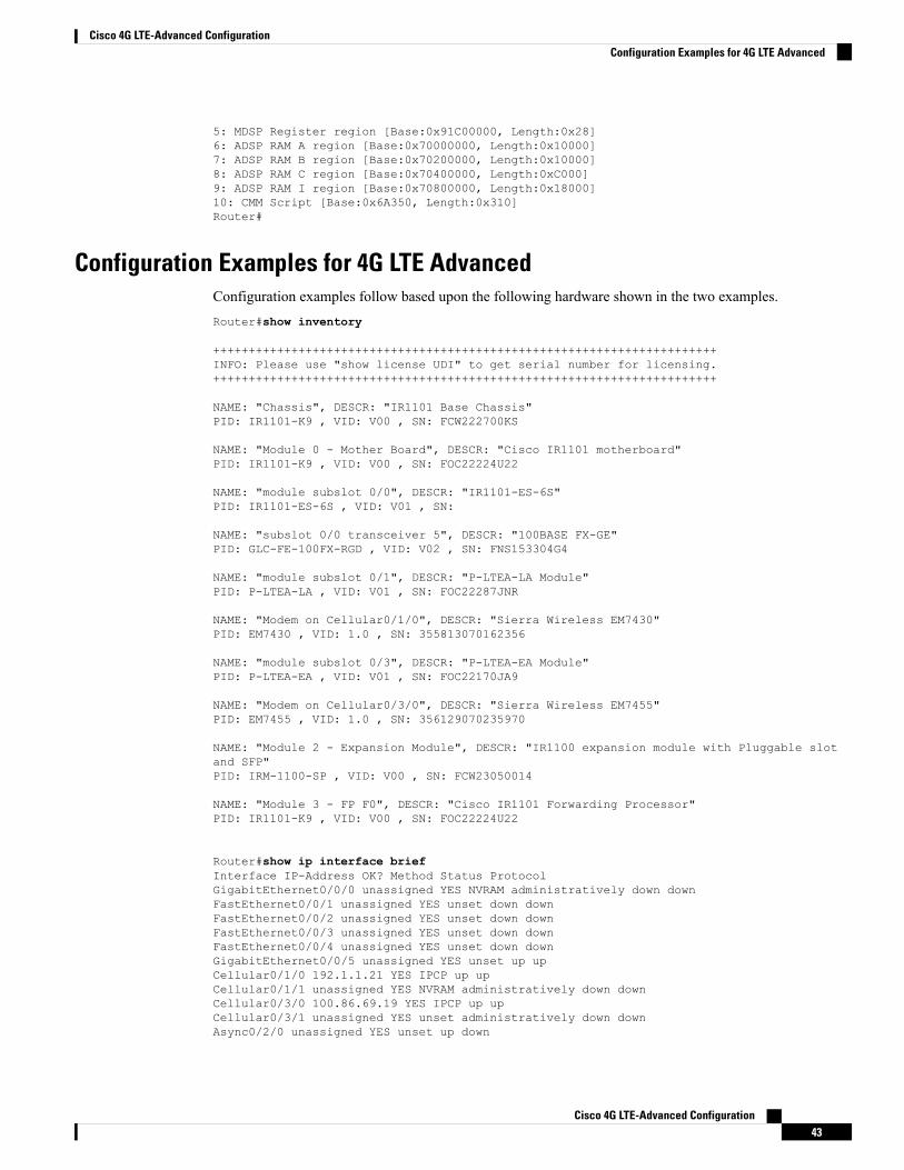
5: MDSP Register region [Base:0x91C00000, Length:0x28]6: ADSP RAM A region [Base:0x70000000, Length:0x10000]7: ADSP RAM B region [Base:0x70200000, Length:0x10000]8: ADSP RAM C region [Base:0x70400000, Length:0xC000]9: ADSP RAM I region [Base:0x70800000, Length:0x18000]10: CMM Script [Base:0x6A350, Length:0x310]Router#
Configuration Examples for 4G LTE AdvancedConfiguration examples follow based upon the following hardware shown in the two examples.Router#show inventory
+++++++++++++++++++++++++++++++++++++++++++++++++++++++++++++++++++++++INFO: Please use "show license UDI" to get serial number for licensing.+++++++++++++++++++++++++++++++++++++++++++++++++++++++++++++++++++++++
NAME: "Chassis", DESCR: "IR1101 Base Chassis"PID: IR1101-K9 , VID: V00 , SN: FCW222700KS
NAME: "Module 0 - Mother Board", DESCR: "Cisco IR1101 motherboard"PID: IR1101-K9 , VID: V00 , SN: FOC22224U22
NAME: "module subslot 0/0", DESCR: "IR1101-ES-6S"PID: IR1101-ES-6S , VID: V01 , SN:
NAME: "subslot 0/0 transceiver 5", DESCR: "100BASE FX-GE"PID: GLC-FE-100FX-RGD , VID: V02 , SN: FNS153304G4
NAME: "module subslot 0/1", DESCR: "P-LTEA-LA Module"PID: P-LTEA-LA , VID: V01 , SN: FOC22287JNR
NAME: "Modem on Cellular0/1/0", DESCR: "Sierra Wireless EM7430"PID: EM7430 , VID: 1.0 , SN: 355813070162356
NAME: "module subslot 0/3", DESCR: "P-LTEA-EA Module"PID: P-LTEA-EA , VID: V01 , SN: FOC22170JA9
NAME: "Modem on Cellular0/3/0", DESCR: "Sierra Wireless EM7455"PID: EM7455 , VID: 1.0 , SN: 356129070235970
NAME: "Module 2 - Expansion Module", DESCR: "IR1100 expansion module with Pluggable slotand SFP"PID: IRM-1100-SP , VID: V00 , SN: FCW23050014
NAME: "Module 3 - FP F0", DESCR: "Cisco IR1101 Forwarding Processor"PID: IR1101-K9 , VID: V00 , SN: FOC22224U22
Router#show ip interface briefInterface IP-Address OK? Method Status ProtocolGigabitEthernet0/0/0 unassigned YES NVRAM administratively down downFastEthernet0/0/1 unassigned YES unset down downFastEthernet0/0/2 unassigned YES unset down downFastEthernet0/0/3 unassigned YES unset down downFastEthernet0/0/4 unassigned YES unset down downGigabitEthernet0/0/5 unassigned YES unset up upCellular0/1/0 192.1.1.21 YES IPCP up upCellular0/1/1 unassigned YES NVRAM administratively down downCellular0/3/0 100.86.69.19 YES IPCP up upCellular0/3/1 unassigned YES unset administratively down downAsync0/2/0 unassigned YES unset up down
Cisco 4G LTE-Advanced Configuration43
Cisco 4G LTE-Advanced ConfigurationConfiguration Examples for 4G LTE Advanced
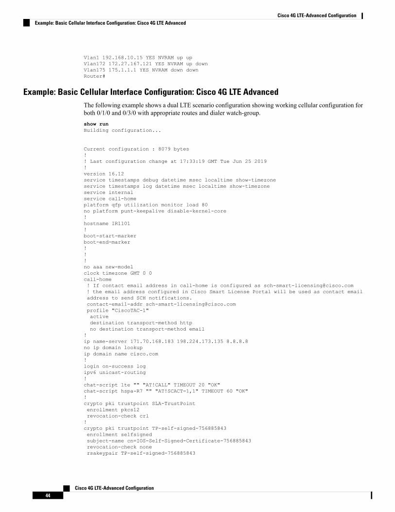
Vlan1 192.168.10.15 YES NVRAM up upVlan172 172.27.167.121 YES NVRAM up downVlan175 175.1.1.1 YES NVRAM down downRouter#
Example: Basic Cellular Interface Configuration: Cisco 4G LTE AdvancedThe following example shows a dual LTE scenario configuration showing working cellular configuration forboth 0/1/0 and 0/3/0 with appropriate routes and dialer watch-group.show runBuilding configuration...
Current configuration : 8079 bytes!! Last configuration change at 17:33:19 GMT Tue Jun 25 2019!version 16.12service timestamps debug datetime msec localtime show-timezoneservice timestamps log datetime msec localtime show-timezoneservice internalservice call-homeplatform qfp utilization monitor load 80no platform punt-keepalive disable-kernel-core!hostname IR1101!boot-start-markerboot-end-marker!!!no aaa new-modelclock timezone GMT 0 0call-home! If contact email address in call-home is configured as [email protected]! the email address configured in Cisco Smart License Portal will be used as contact emailaddress to send SCH notifications.contact-email-addr [email protected] "CiscoTAC-1"activedestination transport-method httpno destination transport-method email
!ip name-server 171.70.168.183 198.224.173.135 8.8.8.8no ip domain lookupip domain name cisco.com!login on-success logipv6 unicast-routing!chat-script lte "" "AT!CALL" TIMEOUT 20 "OK"chat-script hspa-R7 "" "AT!SCACT=1,1" TIMEOUT 60 "OK"!crypto pki trustpoint SLA-TrustPointenrollment pkcs12revocation-check crl!crypto pki trustpoint TP-self-signed-756885843enrollment selfsignedsubject-name cn=IOS-Self-Signed-Certificate-756885843revocation-check nonersakeypair TP-self-signed-756885843
Cisco 4G LTE-Advanced Configuration44
Cisco 4G LTE-Advanced ConfigurationExample: Basic Cellular Interface Configuration: Cisco 4G LTE Advanced
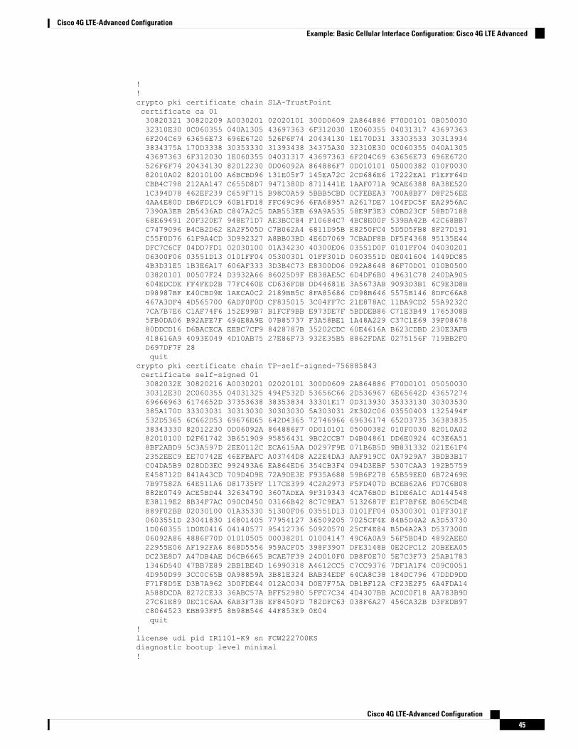
!!crypto pki certificate chain SLA-TrustPointcertificate ca 0130820321 30820209 A0030201 02020101 300D0609 2A864886 F70D0101 0B05003032310E30 0C060355 040A1305 43697363 6F312030 1E060355 04031317 436973636F204C69 63656E73 696E6720 526F6F74 20434130 1E170D31 33303533 303139343834375A 170D3338 30353330 31393438 34375A30 32310E30 0C060355 040A130543697363 6F312030 1E060355 04031317 43697363 6F204C69 63656E73 696E6720526F6F74 20434130 82012230 0D06092A 864886F7 0D010101 05000382 010F003082010A02 82010100 A6BCBD96 131E05F7 145EA72C 2CD686E6 17222EA1 F1EFF64DCBB4C798 212AA147 C655D8D7 9471380D 8711441E 1AAF071A 9CAE6388 8A38E5201C394D78 462EF239 C659F715 B98C0A59 5BBB5CBD 0CFEBEA3 700A8BF7 D8F256EE4AA4E80D DB6FD1C9 60B1FD18 FFC69C96 6FA68957 A2617DE7 104FDC5F EA2956AC7390A3EB 2B5436AD C847A2C5 DAB553EB 69A9A535 58E9F3E3 C0BD23CF 58BD718868E69491 20F320E7 948E71D7 AE3BCC84 F10684C7 4BC8E00F 539BA42B 42C68BB7C7479096 B4CB2D62 EA2F505D C7B062A4 6811D95B E8250FC4 5D5D5FB8 8F27D191C55F0D76 61F9A4CD 3D992327 A8BB03BD 4E6D7069 7CBADF8B DF5F4368 95135E44DFC7C6CF 04DD7FD1 02030100 01A34230 40300E06 03551D0F 0101FF04 0403020106300F06 03551D13 0101FF04 05300301 01FF301D 0603551D 0E041604 1449DC854B3D31E5 1B3E6A17 606AF333 3D3B4C73 E8300D06 092A8648 86F70D01 010B050003820101 00507F24 D3932A66 86025D9F E838AE5C 6D4DF6B0 49631C78 240DA905604EDCDE FF4FED2B 77FC460E CD636FDB DD44681E 3A5673AB 9093D3B1 6C9E3D8BD98987BF E40CBD9E 1AECA0C2 2189BB5C 8FA85686 CD98B646 5575B146 8DFC66A8467A3DF4 4D565700 6ADF0F0D CF835015 3C04FF7C 21E878AC 11BA9CD2 55A9232C7CA7B7E6 C1AF74F6 152E99B7 B1FCF9BB E973DE7F 5BDDEB86 C71E3B49 1765308B5FB0DA06 B92AFE7F 494E8A9E 07B85737 F3A58BE1 1A48A229 C37C1E69 39F0867880DDCD16 D6BACECA EEBC7CF9 8428787B 35202CDC 60E4616A B623CDBD 230E3AFB418616A9 4093E049 4D10AB75 27E86F73 932E35B5 8862FDAE 0275156F 719BB2F0D697DF7F 28quit
crypto pki certificate chain TP-self-signed-756885843certificate self-signed 013082032E 30820216 A0030201 02020101 300D0609 2A864886 F70D0101 0505003030312E30 2C060355 04031325 494F532D 53656C66 2D536967 6E65642D 4365727469666963 6174652D 37353638 38353834 33301E17 0D313930 35333130 30303530385A170D 33303031 30313030 30303030 5A303031 2E302C06 03550403 1325494F532D5365 6C662D53 69676E65 642D4365 72746966 69636174 652D3735 3638383538343330 82012230 0D06092A 864886F7 0D010101 05000382 010F0030 82010A0282010100 D2F61742 3B651909 95856431 9BC2CCB7 D4B04861 DD6E0924 4C3E6A518BF2ABD9 5C3A597D 2EE0112C ECA615AA D0297F9E 071B6B5D 9B831332 021E61F42352EEC9 EE70742E 46EFBAFC A03744D8 A22E4DA3 AAF919CC 0A7929A7 3BDB3B17C04DA5B9 028DD3EC 992493A6 EA864ED6 354CB3F4 094D3EBF 5307CAA3 192B5759E458712D 841A43CD 709D4D9E 72A9DE3E F935A688 59B6F278 65B59EE0 6B72469E7B97582A 64E511A6 D81735FF 117CE399 4C2A2973 F5FD407D BCEB62A6 FD7C6B08882E0749 ACE5BD44 32634790 3607ADEA 9F319343 4CA76B0D B1DE6A1C AD144548E38119E2 8B34F7AC 090C0450 03166B42 8C7C9EA7 5132687F E1F7BF6E B065CD4E889F02BB 02030100 01A35330 51300F06 03551D13 0101FF04 05300301 01FF301F0603551D 23041830 16801405 77954127 36509205 7025CF4E 84B5D4A2 A3D537301D060355 1D0E0416 04140577 95412736 50920570 25CF4E84 B5D4A2A3 D537300D06092A86 4886F70D 01010505 00038201 01004147 49C6A0A9 56F5BD4D 4892AEE022955E06 AF192FA6 868D5556 959ACF05 398F3907 DFE3148B 0E2CFC12 20BEEA05DC23E8D7 A47DB4AE D6CB6665 BCAE7F39 24D010F0 DB8F0E70 5E7C3F73 25AB17831346D540 47BB7E89 2BB1BE4D 16990318 A4612CC5 C7CC9376 7DF1A1F4 C09C00514D950D99 3CC0C65B 0A98859A 3B81E324 BAB34EDF 64CA8C38 184DC796 47DDD9DDF71F8D5E D3B7A962 3D0FDE44 012AC034 D0E7F75A DB1BF12A CF23E2F5 6A4FDA14A588DCDA 8272CE33 36ABC57A BFF52980 5FFC7C34 4D4307BB AC0C0F18 AA783B9D27C61E89 0EC1C6AA 6AB3F73B EF8450FD 782DFC63 038F6A27 456CA32B D3FEDB97C8064523 EBB93FF5 8B98B546 44F853E9 0E04quit
!license udi pid IR1101-K9 sn FCW222700KSdiagnostic bootup level minimal!
Cisco 4G LTE-Advanced Configuration45
Cisco 4G LTE-Advanced ConfigurationExample: Basic Cellular Interface Configuration: Cisco 4G LTE Advanced
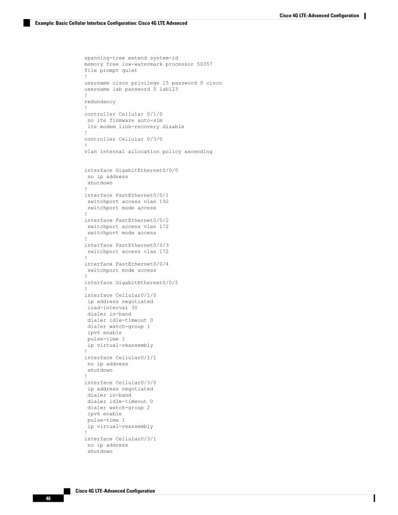
spanning-tree extend system-idmemory free low-watermark processor 50357file prompt quiet!username cisco privilege 15 password 0 ciscousername lab password 0 lab123!redundancy!controller Cellular 0/1/0no lte firmware auto-simlte modem link-recovery disable!controller Cellular 0/3/0!vlan internal allocation policy ascending
interface GigabitEthernet0/0/0no ip addressshutdown!interface FastEthernet0/0/1switchport access vlan 192switchport mode access!interface FastEthernet0/0/2switchport access vlan 172switchport mode access!interface FastEthernet0/0/3switchport access vlan 172!interface FastEthernet0/0/4switchport mode access!interface GigabitEthernet0/0/5!interface Cellular0/1/0ip address negotiatedload-interval 30dialer in-banddialer idle-timeout 0dialer watch-group 1ipv6 enablepulse-time 1ip virtual-reassembly!interface Cellular0/1/1no ip addressshutdown!interface Cellular0/3/0ip address negotiateddialer in-banddialer idle-timeout 0dialer watch-group 2ipv6 enablepulse-time 1ip virtual-reassembly!interface Cellular0/3/1no ip addressshutdown
Cisco 4G LTE-Advanced Configuration46
Cisco 4G LTE-Advanced ConfigurationExample: Basic Cellular Interface Configuration: Cisco 4G LTE Advanced
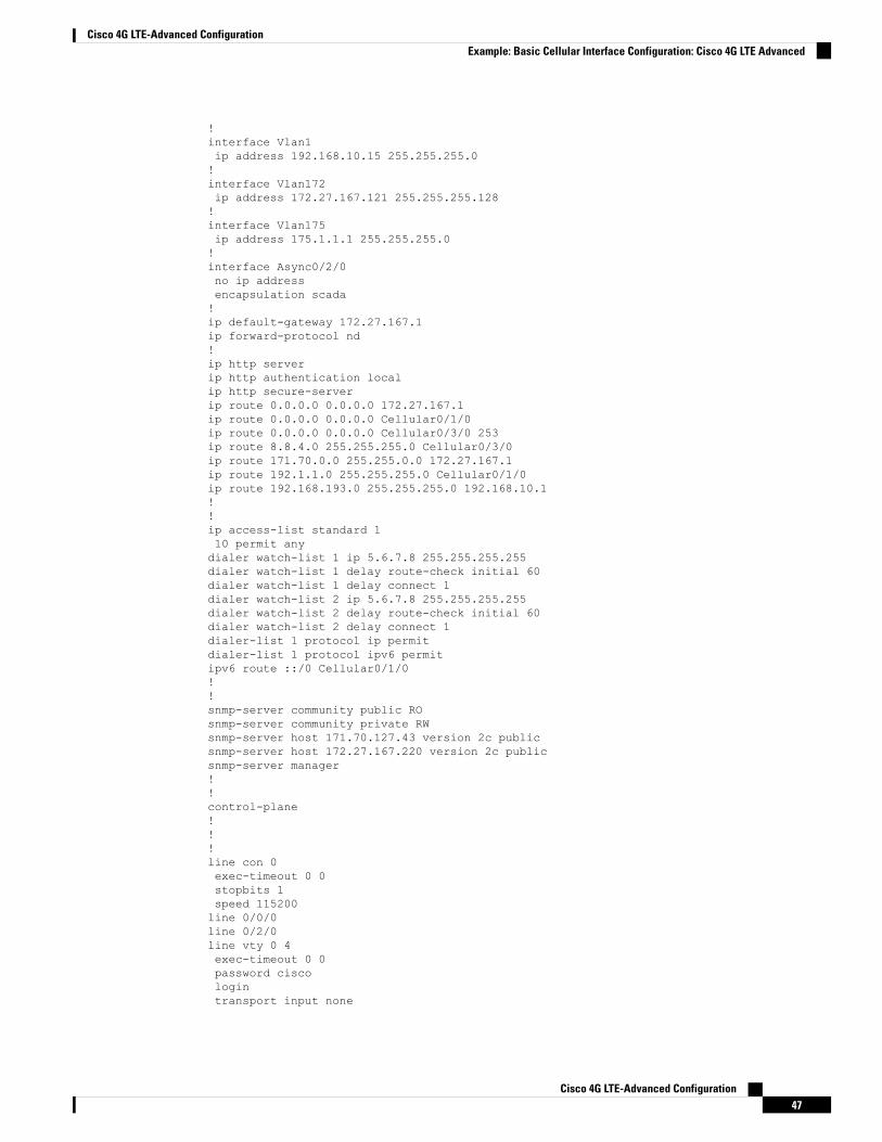
!interface Vlan1ip address 192.168.10.15 255.255.255.0!interface Vlan172ip address 172.27.167.121 255.255.255.128!interface Vlan175ip address 175.1.1.1 255.255.255.0!interface Async0/2/0no ip addressencapsulation scada!ip default-gateway 172.27.167.1ip forward-protocol nd!ip http serverip http authentication localip http secure-serverip route 0.0.0.0 0.0.0.0 172.27.167.1ip route 0.0.0.0 0.0.0.0 Cellular0/1/0ip route 0.0.0.0 0.0.0.0 Cellular0/3/0 253ip route 8.8.4.0 255.255.255.0 Cellular0/3/0ip route 171.70.0.0 255.255.0.0 172.27.167.1ip route 192.1.1.0 255.255.255.0 Cellular0/1/0ip route 192.168.193.0 255.255.255.0 192.168.10.1!!ip access-list standard 110 permit anydialer watch-list 1 ip 5.6.7.8 255.255.255.255dialer watch-list 1 delay route-check initial 60dialer watch-list 1 delay connect 1dialer watch-list 2 ip 5.6.7.8 255.255.255.255dialer watch-list 2 delay route-check initial 60dialer watch-list 2 delay connect 1dialer-list 1 protocol ip permitdialer-list 1 protocol ipv6 permitipv6 route ::/0 Cellular0/1/0!!snmp-server community public ROsnmp-server community private RWsnmp-server host 171.70.127.43 version 2c publicsnmp-server host 172.27.167.220 version 2c publicsnmp-server manager!!control-plane!!!line con 0exec-timeout 0 0stopbits 1speed 115200line 0/0/0line 0/2/0line vty 0 4exec-timeout 0 0password ciscologintransport input none
Cisco 4G LTE-Advanced Configuration47
Cisco 4G LTE-Advanced ConfigurationExample: Basic Cellular Interface Configuration: Cisco 4G LTE Advanced
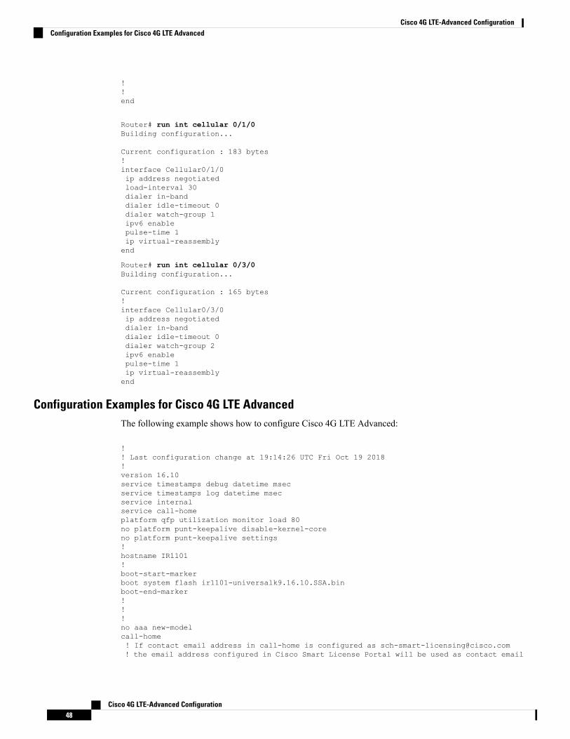
!!end
Router# run int cellular 0/1/0Building configuration...
Current configuration : 183 bytes!interface Cellular0/1/0ip address negotiatedload-interval 30dialer in-banddialer idle-timeout 0dialer watch-group 1ipv6 enablepulse-time 1ip virtual-reassemblyend
Router# run int cellular 0/3/0Building configuration...
Current configuration : 165 bytes!interface Cellular0/3/0ip address negotiateddialer in-banddialer idle-timeout 0dialer watch-group 2ipv6 enablepulse-time 1ip virtual-reassemblyend
Configuration Examples for Cisco 4G LTE AdvancedThe following example shows how to configure Cisco 4G LTE Advanced:
!! Last configuration change at 19:14:26 UTC Fri Oct 19 2018!version 16.10service timestamps debug datetime msecservice timestamps log datetime msecservice internalservice call-homeplatform qfp utilization monitor load 80no platform punt-keepalive disable-kernel-coreno platform punt-keepalive settings!hostname IR1101!boot-start-markerboot system flash ir1101-universalk9.16.10.SSA.binboot-end-marker!!!no aaa new-modelcall-home! If contact email address in call-home is configured as [email protected]! the email address configured in Cisco Smart License Portal will be used as contact email
Cisco 4G LTE-Advanced Configuration48
Cisco 4G LTE-Advanced ConfigurationConfiguration Examples for Cisco 4G LTE Advanced
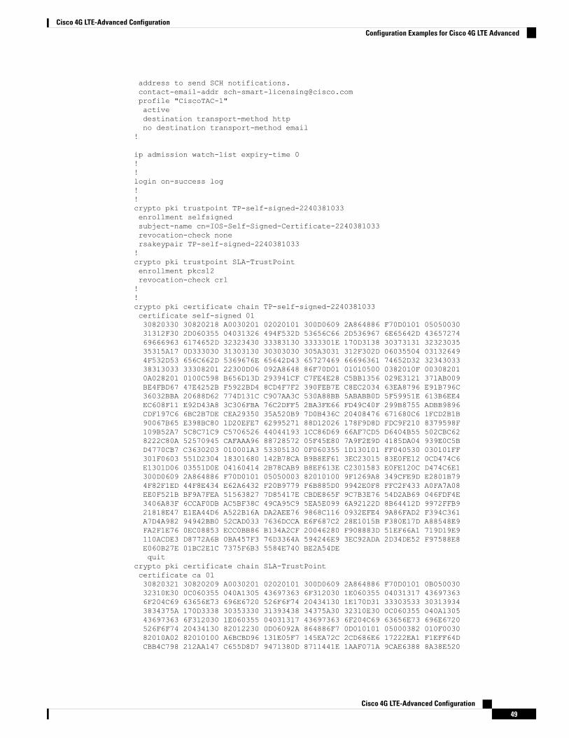
address to send SCH notifications.contact-email-addr [email protected] "CiscoTAC-1"activedestination transport-method httpno destination transport-method email
!
ip admission watch-list expiry-time 0!!login on-success log!!crypto pki trustpoint TP-self-signed-2240381033enrollment selfsignedsubject-name cn=IOS-Self-Signed-Certificate-2240381033revocation-check nonersakeypair TP-self-signed-2240381033!crypto pki trustpoint SLA-TrustPointenrollment pkcs12revocation-check crl!!crypto pki certificate chain TP-self-signed-2240381033certificate self-signed 0130820330 30820218 A0030201 02020101 300D0609 2A864886 F70D0101 0505003031312F30 2D060355 04031326 494F532D 53656C66 2D536967 6E65642D 4365727469666963 6174652D 32323430 33383130 3333301E 170D3138 30373131 3232303535315A17 0D333030 31303130 30303030 305A3031 312F302D 06035504 031326494F532D53 656C662D 5369676E 65642D43 65727469 66696361 74652D32 3234303338313033 33308201 22300D06 092A8648 86F70D01 01010500 0382010F 003082010A028201 0100C598 B656D13D 293941CF C7FE4E28 C5BB1356 029E3121 371AB009BE4FBD67 47E4252B F5922BD4 8CD4F7F2 390FEB7E C8EC2034 63EA8796 E91B796C36032BBA 20688D62 774D131C C907AA3C 530A88BB 5ABABB0D 5F59951E 613B6EE4EC608F11 E92D43A8 3C306FBA 76C2DFF5 2BA3FE66 FD49C40F 299B8755 ADBB9896CDF197C6 6BC2B7DE CEA29350 35A520B9 7D0B436C 20408476 671680C6 1FCD2B1B90067B65 E398BC80 1D20EFE7 62995271 88D12026 178F9D8D FDC9F210 8379598F109B52A7 5C8C71C9 C5706526 44044193 1CC86D69 66AF7CD5 D6404B55 502CBC628222C80A 52570945 CAFAAA96 88728572 05F45E80 7A9F2E9D 4185DA04 939E0C5BD4770CB7 C3630203 010001A3 53305130 0F060355 1D130101 FF040530 030101FF301F0603 551D2304 18301680 142B78CA B9B8EF61 3EC23015 83E0FE12 0CD474C6E1301D06 03551D0E 04160414 2B78CAB9 B8EF613E C2301583 E0FE120C D474C6E1300D0609 2A864886 F70D0101 05050003 82010100 9F1269A8 349CFE9D E2801B794F82F1ED 44F8E434 E62A6432 F20B9779 F6B885D0 9942E0F8 FFC2F433 A0FA7A08EE0F521B BF9A7FEA 51563827 7D85417E CBDE865F 9C7B3E76 54D2AB69 046FDF4E3406A83F 6CCAF0DB AC5BF38C 49CA95C9 5EA5E099 6A92122D 8B64412D 9972FFB921818E47 E1EA44D6 A522B16A DA2AEE76 9868C116 0932EFE4 9A86FAD2 F394C361A7D4A982 94942BB0 52CAD033 7636DCCA E6F687C2 28E1015B F380E17D A88548E9FA2F1E76 0EC08853 ECC0BB86 B134A2CF 20046280 F908883D 51EF66A1 719D19E9110ACDE3 D8772A6B 0BA457F3 76D3364A 594246E9 3EC92ADA 2D34DE52 F97588E8E060B27E 01BC2E1C 7375F6B3 5584E740 BE2A54DEquit
crypto pki certificate chain SLA-TrustPointcertificate ca 0130820321 30820209 A0030201 02020101 300D0609 2A864886 F70D0101 0B05003032310E30 0C060355 040A1305 43697363 6F312030 1E060355 04031317 436973636F204C69 63656E73 696E6720 526F6F74 20434130 1E170D31 33303533 303139343834375A 170D3338 30353330 31393438 34375A30 32310E30 0C060355 040A130543697363 6F312030 1E060355 04031317 43697363 6F204C69 63656E73 696E6720526F6F74 20434130 82012230 0D06092A 864886F7 0D010101 05000382 010F003082010A02 82010100 A6BCBD96 131E05F7 145EA72C 2CD686E6 17222EA1 F1EFF64DCBB4C798 212AA147 C655D8D7 9471380D 8711441E 1AAF071A 9CAE6388 8A38E520
Cisco 4G LTE-Advanced Configuration49
Cisco 4G LTE-Advanced ConfigurationConfiguration Examples for Cisco 4G LTE Advanced
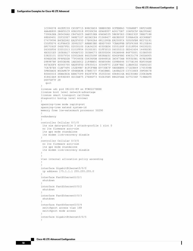
1C394D78 462EF239 C659F715 B98C0A59 5BBB5CBD 0CFEBEA3 700A8BF7 D8F256EE4AA4E80D DB6FD1C9 60B1FD18 FFC69C96 6FA68957 A2617DE7 104FDC5F EA2956AC7390A3EB 2B5436AD C847A2C5 DAB553EB 69A9A535 58E9F3E3 C0BD23CF 58BD718868E69491 20F320E7 948E71D7 AE3BCC84 F10684C7 4BC8E00F 539BA42B 42C68BB7C7479096 B4CB2D62 EA2F505D C7B062A4 6811D95B E8250FC4 5D5D5FB8 8F27D191C55F0D76 61F9A4CD 3D992327 A8BB03BD 4E6D7069 7CBADF8B DF5F4368 95135E44DFC7C6CF 04DD7FD1 02030100 01A34230 40300E06 03551D0F 0101FF04 0403020106300F06 03551D13 0101FF04 05300301 01FF301D 0603551D 0E041604 1449DC854B3D31E5 1B3E6A17 606AF333 3D3B4C73 E8300D06 092A8648 86F70D01 010B050003820101 00507F24 D3932A66 86025D9F E838AE5C 6D4DF6B0 49631C78 240DA905604EDCDE FF4FED2B 77FC460E CD636FDB DD44681E 3A5673AB 9093D3B1 6C9E3D8BD98987BF E40CBD9E 1AECA0C2 2189BB5C 8FA85686 CD98B646 5575B146 8DFC66A8467A3DF4 4D565700 6ADF0F0D CF835015 3C04FF7C 21E878AC 11BA9CD2 55A9232C7CA7B7E6 C1AF74F6 152E99B7 B1FCF9BB E973DE7F 5BDDEB86 C71E3B49 1765308B5FB0DA06 B92AFE7F 494E8A9E 07B85737 F3A58BE1 1A48A229 C37C1E69 39F0867880DDCD16 D6BACECA EEBC7CF9 8428787B 35202CDC 60E4616A B623CDBD 230E3AFB418616A9 4093E049 4D10AB75 27E86F73 932E35B5 8862FDAE 0275156F 719BB2F0D697DF7F 28quit
!license udi pid IR1101-K9 sn FCW2227XXXXlicense boot level network-advantagelicense smart transport callhomediagnostic bootup level minimal!spanning-tree mode rapid-pvstspanning-tree extend system-idmemory free low-watermark processor 50290!redundancy!controller Cellular 0/1/0lte sim data-profile 3 attach-profile 1 slot 0no lte firmware auto-simlte gps mode standalonelte modem link-recovery disable!controller Cellular 0/3/0no lte firmware auto-simlte gps mode standalonelte modem link-recovery disable!!vlan internal allocation policy ascending!!interface GigabitEthernet0/0/0ip address 175.1.1.1 255.255.255.0!interface FastEthernet0/0/1shutdown!interface FastEthernet0/0/2shutdown!interface FastEthernet0/0/3shutdown!interface FastEthernet0/0/4switchport access vlan 168switchport mode access!interface GigabitEthernet0/0/5!
Cisco 4G LTE-Advanced Configuration50
Cisco 4G LTE-Advanced ConfigurationConfiguration Examples for Cisco 4G LTE Advanced
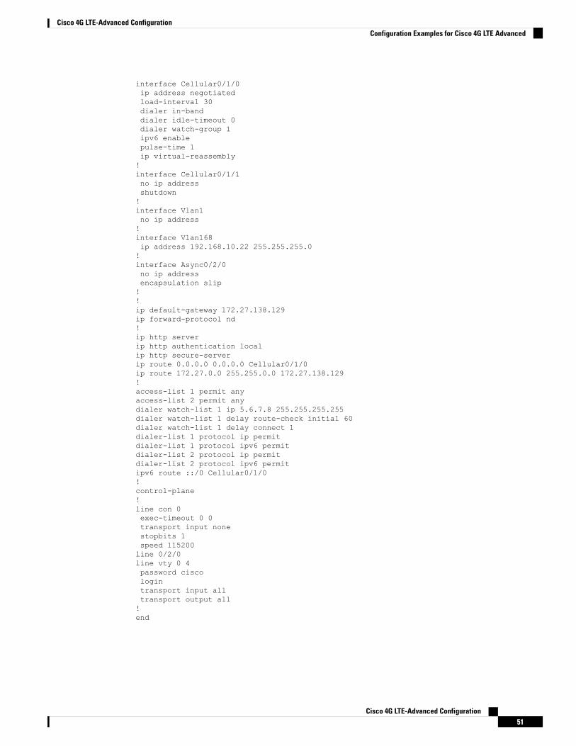
interface Cellular0/1/0ip address negotiatedload-interval 30dialer in-banddialer idle-timeout 0dialer watch-group 1ipv6 enablepulse-time 1ip virtual-reassembly!interface Cellular0/1/1no ip addressshutdown!interface Vlan1no ip address!interface Vlan168ip address 192.168.10.22 255.255.255.0!interface Async0/2/0no ip addressencapsulation slip!!ip default-gateway 172.27.138.129ip forward-protocol nd!ip http serverip http authentication localip http secure-serverip route 0.0.0.0 0.0.0.0 Cellular0/1/0ip route 172.27.0.0 255.255.0.0 172.27.138.129!access-list 1 permit anyaccess-list 2 permit anydialer watch-list 1 ip 5.6.7.8 255.255.255.255dialer watch-list 1 delay route-check initial 60dialer watch-list 1 delay connect 1dialer-list 1 protocol ip permitdialer-list 1 protocol ipv6 permitdialer-list 2 protocol ip permitdialer-list 2 protocol ipv6 permitipv6 route ::/0 Cellular0/1/0!control-plane!line con 0exec-timeout 0 0transport input nonestopbits 1speed 115200line 0/2/0line vty 0 4password ciscologintransport input alltransport output all!end
Cisco 4G LTE-Advanced Configuration51
Cisco 4G LTE-Advanced ConfigurationConfiguration Examples for Cisco 4G LTE Advanced
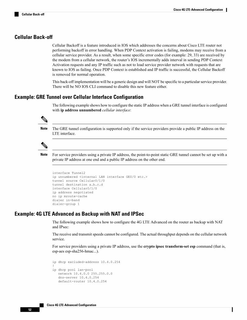
Cellular Back-offCellular Backoff is a feature introduced in IOS which addresses the concerns about Cisco LTE router notperforming backoff in error handling. When PDP Context activation is failing, modems may receive from acellular service provider. As a result, when some specific error codes (for example: 29, 33) are received bythe modem from a cellular network, the router’s IOS incrementally adds interval in sending PDP ContextActivation requests and any IP traffic such as not to load service provider network with requests that areknown to IOS as failing. Once PDP Context is established and IP traffic is successful, the Cellular Backoffis removed for normal operation.
This back-off implementation will be a generic design and will NOT be specific to a particular service provider.There will be NO IOS CLI command to disable this new feature either.
Example: GRE Tunnel over Cellular Interface ConfigurationThe following example shows how to configure the static IP address when a GRE tunnel interface is configuredwith ip address unnumbered cellular interface:
The GRE tunnel configuration is supported only if the service providers provide a public IP address on theLTE interface.
Note
For service providers using a private IP address, the point-to-point static GRE tunnel cannot be set up with aprivate IP address at one end and a public IP address on the other end.
Note
interface Tunnel2ip unnumbered <internal LAN interface GE0/0 etc.>tunnel source Cellular0/1/0tunnel destination a.b.c.dinterface Cellular0/1/0ip address negotiatedno ip mroute-cachedialer in-banddialer-group 1
Example: 4G LTE Advanced as Backup with NAT and IPSecThe following example shows how to configure the 4G LTE Advanced on the router as backup with NATand IPsec:
The receive and transmit speeds cannot be configured. The actual throughput depends on the cellular networkservice.
For service providers using a private IP address, use the crypto ipsec transform-set esp command (that is,esp-aes esp-sha256-hmac...).
ip dhcp excluded-address 10.4.0.254!ip dhcp pool lan-pool
network 10.4.0.0 255.255.0.0dns-server 10.4.0.254default-router 10.4.0.254
Cisco 4G LTE-Advanced Configuration52
Cisco 4G LTE-Advanced ConfigurationCellular Back-off
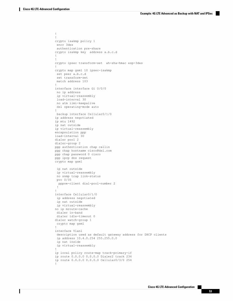
!!crypto isakmp policy 1encr 3desauthentication pre-sharecrypto isakmp key address a.b.c.d!!crypto ipsec transform-set ah-sha-hmac esp-3des!crypto map gsm1 10 ipsec-isakmpset peer a.b.c.dset transform-setmatch address 103!interface interface Gi 0/0/0no ip addressip virtual-reassemblyload-interval 30no atm ilmi-keepalivedsl operating-mode auto!backup interface Cellular0/1/0ip address negotiatedip mtu 1492ip nat outsideip virtual-reassemblyencapsulation pppload-interval 30dialer pool 2dialer-group 2ppp authentication chap callinppp chap hostname [email protected] chap password 0 ciscoppp ipcp dns requestcrypto map gsm1
ip nat outsideip virtual-reassemblyno snmp trap link-statuspvc 0/35pppoe-client dial-pool-number 2!!interface Cellular0/1/0ip address negotiatedip nat outsideip virtual-reassemblyno ip mroute-cachedialer in-banddialer idle-timeout 0dialer watch-group 1crypto map gsm1!interface Vlan1description used as default gateway address for DHCP clientsip address 10.4.0.254 255.255.0.0ip nat insideip virtual-reassembly!ip local policy route-map track-primary-ifip route 0.0.0.0 0.0.0.0 Dialer2 track 234ip route 0.0.0.0 0.0.0.0 Cellular0/3/0 254!
Cisco 4G LTE-Advanced Configuration53
Cisco 4G LTE-Advanced ConfigurationExample: 4G LTE Advanced as Backup with NAT and IPSec
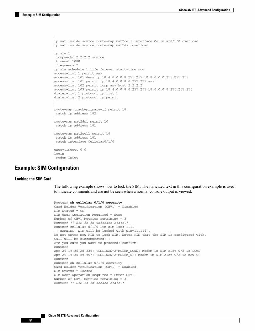
!ip nat inside source route-map nat2cell interface Cellular0/1/0 overloadip nat inside source route-map nat2dsl overload!ip sla 1icmp-echo 2.2.2.2 sourcetimeout 1000frequency 2ip sla schedule 1 life forever start-time nowaccess-list 1 permit anyaccess-list 101 deny ip 10.4.0.0 0.0.255.255 10.0.0.0 0.255.255.255access-list 101 permit ip 10.4.0.0 0.0.255.255 anyaccess-list 102 permit icmp any host 2.2.2.2access-list 103 permit ip 10.4.0.0 0.0.255.255 10.0.0.0 0.255.255.255dialer-list 1 protocol ip list 1dialer-list 2 protocol ip permit!!route-map track-primary-if permit 10match ip address 102!route-map nat2dsl permit 10match ip address 101!route-map nat2cell permit 10match ip address 101match interface Cellular0/1/0!exec-timeout 0 0loginmodem InOut
Example: SIM Configuration
Locking the SIM Card
The following example shows how to lock the SIM. The italicized text in this configuration example is usedto indicate comments and are not be seen when a normal console output is viewed.
Router# sh cellular 0/1/0 securityCard Holder Verification (CHV1) = DisabledSIM Status = OKSIM User Operation Required = NoneNumber of CHV1 Retries remaining = 3Router# !! SIM is in unlocked state.!Router# cellular 0/1/0 lte sim lock 1111!!!WARNING: SIM will be locked with pin=1111(4).Do not enter new PIN to lock SIM. Enter PIN that the SIM is configured with.Call will be disconnected!!!Are you sure you want to proceed?[confirm]Router#Apr 26 19:35:28.339: %CELLWAN-2-MODEM_DOWN: Modem in NIM slot 0/2 is DOWNApr 26 19:35:59.967: %CELLWAN-2-MODEM_UP: Modem in NIM slot 0/2 is now UPRouter#Router# sh cellular 0/1/0 securityCard Holder Verification (CHV1) = EnabledSIM Status = LockedSIM User Operation Required = Enter CHV1Number of CHV1 Retries remaining = 3Router# !! SIM is in locked state.!
Cisco 4G LTE-Advanced Configuration54
Cisco 4G LTE-Advanced ConfigurationExample: SIM Configuration
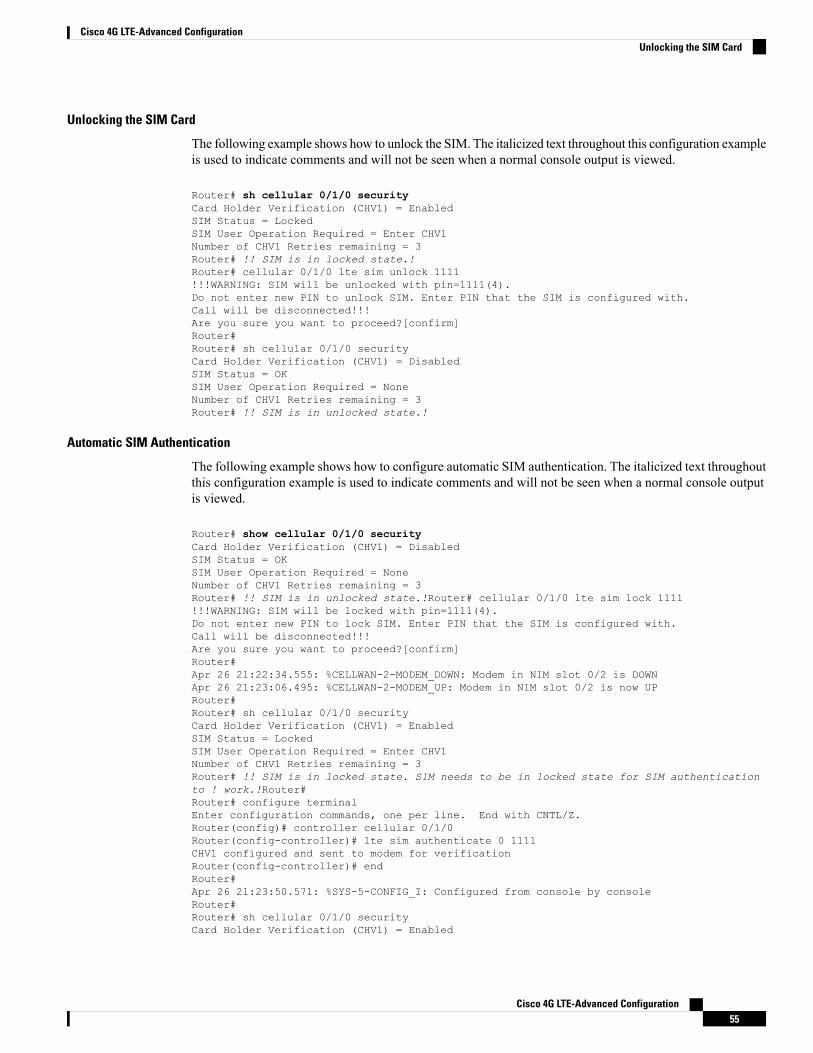
Unlocking the SIM Card
The following example shows how to unlock the SIM. The italicized text throughout this configuration exampleis used to indicate comments and will not be seen when a normal console output is viewed.
Router# sh cellular 0/1/0 securityCard Holder Verification (CHV1) = EnabledSIM Status = LockedSIM User Operation Required = Enter CHV1Number of CHV1 Retries remaining = 3Router# !! SIM is in locked state.!Router# cellular 0/1/0 lte sim unlock 1111!!!WARNING: SIM will be unlocked with pin=1111(4).Do not enter new PIN to unlock SIM. Enter PIN that the SIM is configured with.Call will be disconnected!!!Are you sure you want to proceed?[confirm]Router#Router# sh cellular 0/1/0 securityCard Holder Verification (CHV1) = DisabledSIM Status = OKSIM User Operation Required = NoneNumber of CHV1 Retries remaining = 3Router# !! SIM is in unlocked state.!
Automatic SIM Authentication
The following example shows how to configure automatic SIM authentication. The italicized text throughoutthis configuration example is used to indicate comments and will not be seen when a normal console outputis viewed.
Router# show cellular 0/1/0 securityCard Holder Verification (CHV1) = DisabledSIM Status = OKSIM User Operation Required = NoneNumber of CHV1 Retries remaining = 3Router# !! SIM is in unlocked state.!Router# cellular 0/1/0 lte sim lock 1111!!!WARNING: SIM will be locked with pin=1111(4).Do not enter new PIN to lock SIM. Enter PIN that the SIM is configured with.Call will be disconnected!!!Are you sure you want to proceed?[confirm]Router#Apr 26 21:22:34.555: %CELLWAN-2-MODEM_DOWN: Modem in NIM slot 0/2 is DOWNApr 26 21:23:06.495: %CELLWAN-2-MODEM_UP: Modem in NIM slot 0/2 is now UPRouter#Router# sh cellular 0/1/0 securityCard Holder Verification (CHV1) = EnabledSIM Status = LockedSIM User Operation Required = Enter CHV1Number of CHV1 Retries remaining = 3Router# !! SIM is in locked state. SIM needs to be in locked state for SIM authenticationto ! work.!Router#Router# configure terminalEnter configuration commands, one per line. End with CNTL/Z.Router(config)# controller cellular 0/1/0Router(config-controller)# lte sim authenticate 0 1111CHV1 configured and sent to modem for verificationRouter(config-controller)# endRouter#Apr 26 21:23:50.571: %SYS-5-CONFIG_I: Configured from console by consoleRouter#Router# sh cellular 0/1/0 securityCard Holder Verification (CHV1) = Enabled
Cisco 4G LTE-Advanced Configuration55
Cisco 4G LTE-Advanced ConfigurationUnlocking the SIM Card
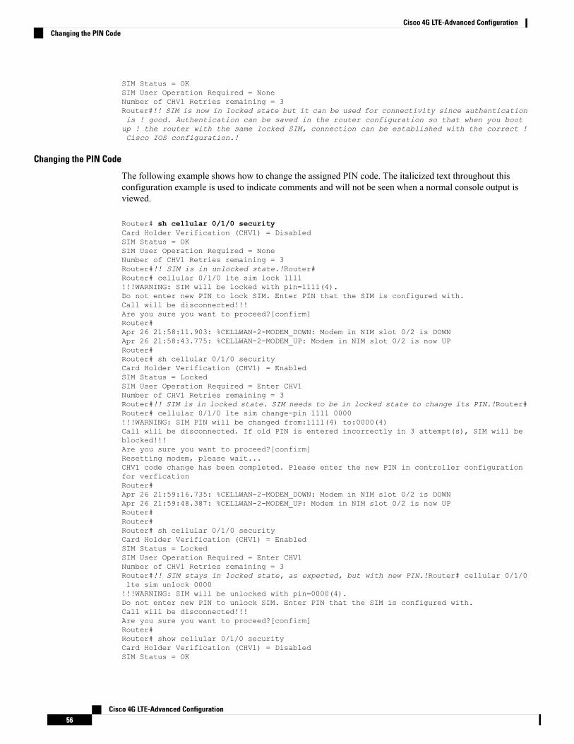
SIM Status = OKSIM User Operation Required = NoneNumber of CHV1 Retries remaining = 3Router#!! SIM is now in locked state but it can be used for connectivity since authenticationis ! good. Authentication can be saved in the router configuration so that when you bootup ! the router with the same locked SIM, connection can be established with the correct !Cisco IOS configuration.!
Changing the PIN Code
The following example shows how to change the assigned PIN code. The italicized text throughout thisconfiguration example is used to indicate comments and will not be seen when a normal console output isviewed.
Router# sh cellular 0/1/0 securityCard Holder Verification (CHV1) = DisabledSIM Status = OKSIM User Operation Required = NoneNumber of CHV1 Retries remaining = 3Router#!! SIM is in unlocked state.!Router#Router# cellular 0/1/0 lte sim lock 1111!!!WARNING: SIM will be locked with pin=1111(4).Do not enter new PIN to lock SIM. Enter PIN that the SIM is configured with.Call will be disconnected!!!Are you sure you want to proceed?[confirm]Router#Apr 26 21:58:11.903: %CELLWAN-2-MODEM_DOWN: Modem in NIM slot 0/2 is DOWNApr 26 21:58:43.775: %CELLWAN-2-MODEM_UP: Modem in NIM slot 0/2 is now UPRouter#Router# sh cellular 0/1/0 securityCard Holder Verification (CHV1) = EnabledSIM Status = LockedSIM User Operation Required = Enter CHV1Number of CHV1 Retries remaining = 3Router#!! SIM is in locked state. SIM needs to be in locked state to change its PIN.!Router#Router# cellular 0/1/0 lte sim change-pin 1111 0000!!!WARNING: SIM PIN will be changed from:1111(4) to:0000(4)Call will be disconnected. If old PIN is entered incorrectly in 3 attempt(s), SIM will beblocked!!!Are you sure you want to proceed?[confirm]Resetting modem, please wait...CHV1 code change has been completed. Please enter the new PIN in controller configurationfor verficationRouter#Apr 26 21:59:16.735: %CELLWAN-2-MODEM_DOWN: Modem in NIM slot 0/2 is DOWNApr 26 21:59:48.387: %CELLWAN-2-MODEM_UP: Modem in NIM slot 0/2 is now UPRouter#Router#Router# sh cellular 0/1/0 securityCard Holder Verification (CHV1) = EnabledSIM Status = LockedSIM User Operation Required = Enter CHV1Number of CHV1 Retries remaining = 3Router#!! SIM stays in locked state, as expected, but with new PIN.!Router# cellular 0/1/0lte sim unlock 0000!!!WARNING: SIM will be unlocked with pin=0000(4).Do not enter new PIN to unlock SIM. Enter PIN that the SIM is configured with.Call will be disconnected!!!Are you sure you want to proceed?[confirm]Router#Router# show cellular 0/1/0 securityCard Holder Verification (CHV1) = DisabledSIM Status = OK
Cisco 4G LTE-Advanced Configuration56
Cisco 4G LTE-Advanced ConfigurationChanging the PIN Code
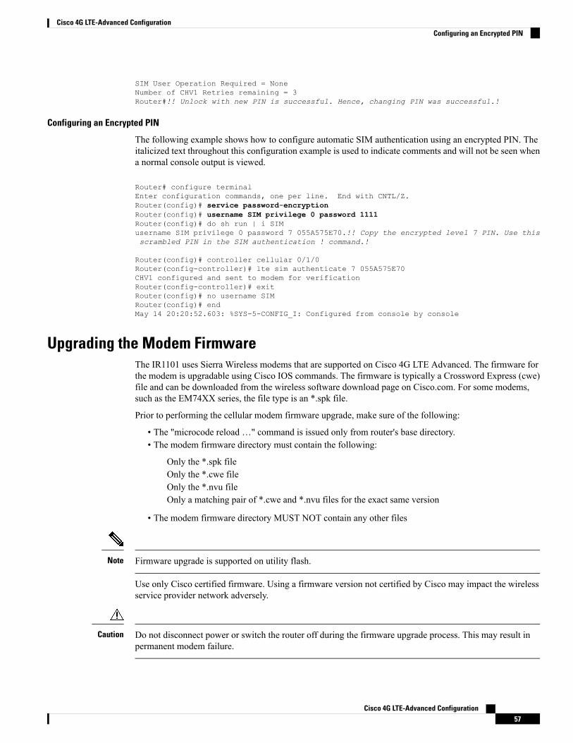
SIM User Operation Required = NoneNumber of CHV1 Retries remaining = 3Router#!! Unlock with new PIN is successful. Hence, changing PIN was successful.!
Configuring an Encrypted PIN
The following example shows how to configure automatic SIM authentication using an encrypted PIN. Theitalicized text throughout this configuration example is used to indicate comments and will not be seen whena normal console output is viewed.
Router# configure terminalEnter configuration commands, one per line. End with CNTL/Z.Router(config)# service password-encryptionRouter(config)# username SIM privilege 0 password 1111Router(config)# do sh run | i SIMusername SIM privilege 0 password 7 055A575E70.!! Copy the encrypted level 7 PIN. Use thisscrambled PIN in the SIM authentication ! command.!
Router(config)# controller cellular 0/1/0Router(config-controller)# lte sim authenticate 7 055A575E70CHV1 configured and sent to modem for verificationRouter(config-controller)# exitRouter(config)# no username SIMRouter(config)# endMay 14 20:20:52.603: %SYS-5-CONFIG_I: Configured from console by console
Upgrading the Modem FirmwareThe IR1101 uses Sierra Wireless modems that are supported on Cisco 4G LTE Advanced. The firmware forthe modem is upgradable using Cisco IOS commands. The firmware is typically a Crossword Express (cwe)file and can be downloaded from the wireless software download page on Cisco.com. For some modems,such as the EM74XX series, the file type is an *.spk file.
Prior to performing the cellular modem firmware upgrade, make sure of the following:
• The "microcode reload …" command is issued only from router's base directory.• The modem firmware directory must contain the following:
Only the *.spk fileOnly the *.cwe fileOnly the *.nvu fileOnly a matching pair of *.cwe and *.nvu files for the exact same version
• The modem firmware directory MUST NOT contain any other files
Firmware upgrade is supported on utility flash.Note
Use only Cisco certified firmware. Using a firmware version not certified by Cisco may impact the wirelessservice provider network adversely.
Do not disconnect power or switch the router off during the firmware upgrade process. This may result inpermanent modem failure.
Caution
Cisco 4G LTE-Advanced Configuration57
Cisco 4G LTE-Advanced ConfigurationConfiguring an Encrypted PIN
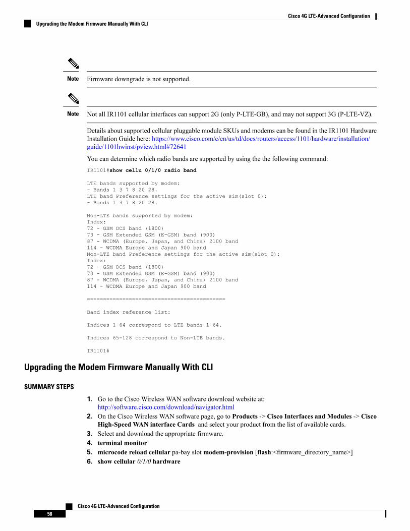
Firmware downgrade is not supported.Note
Not all IR1101 cellular interfaces can support 2G (only P-LTE-GB), and may not support 3G (P-LTE-VZ).Note
Details about supported cellular pluggable module SKUs and modems can be found in the IR1101 HardwareInstallation Guide here: https://www.cisco.com/c/en/us/td/docs/routers/access/1101/hardware/installation/guide/1101hwinst/pview.html#72641
You can determine which radio bands are supported by using the the following command:IR1101#show cellu 0/1/0 radio band
LTE bands supported by modem:- Bands 1 3 7 8 20 28.LTE band Preference settings for the active sim(slot 0):- Bands 1 3 7 8 20 28.
Non-LTE bands supported by modem:Index:72 - GSM DCS band (1800)73 - GSM Extended GSM (E-GSM) band (900)87 - WCDMA (Europe, Japan, and China) 2100 band114 - WCDMA Europe and Japan 900 bandNon-LTE band Preference settings for the active sim(slot 0):Index:72 - GSM DCS band (1800)73 - GSM Extended GSM (E-GSM) band (900)87 - WCDMA (Europe, Japan, and China) 2100 band114 - WCDMA Europe and Japan 900 band
===========================================
Band index reference list:
Indices 1-64 correspond to LTE bands 1-64.
Indices 65-128 correspond to Non-LTE bands.
IR1101#
Upgrading the Modem Firmware Manually With CLI
SUMMARY STEPS
1. Go to the Cisco Wireless WAN software download website at:http://software.cisco.com/download/navigator.html
2. On the Cisco Wireless WAN software page, go to Products -> Cisco Interfaces and Modules -> CiscoHigh-Speed WAN interface Cards and select your product from the list of available cards.
3. Select and download the appropriate firmware.4. terminal monitor5. microcode reload cellular pa-bay slotmodem-provision [flash:<firmware_directory_name>]6. show cellular 0/1/0 hardware
Cisco 4G LTE-Advanced Configuration58
Cisco 4G LTE-Advanced ConfigurationUpgrading the Modem Firmware Manually With CLI
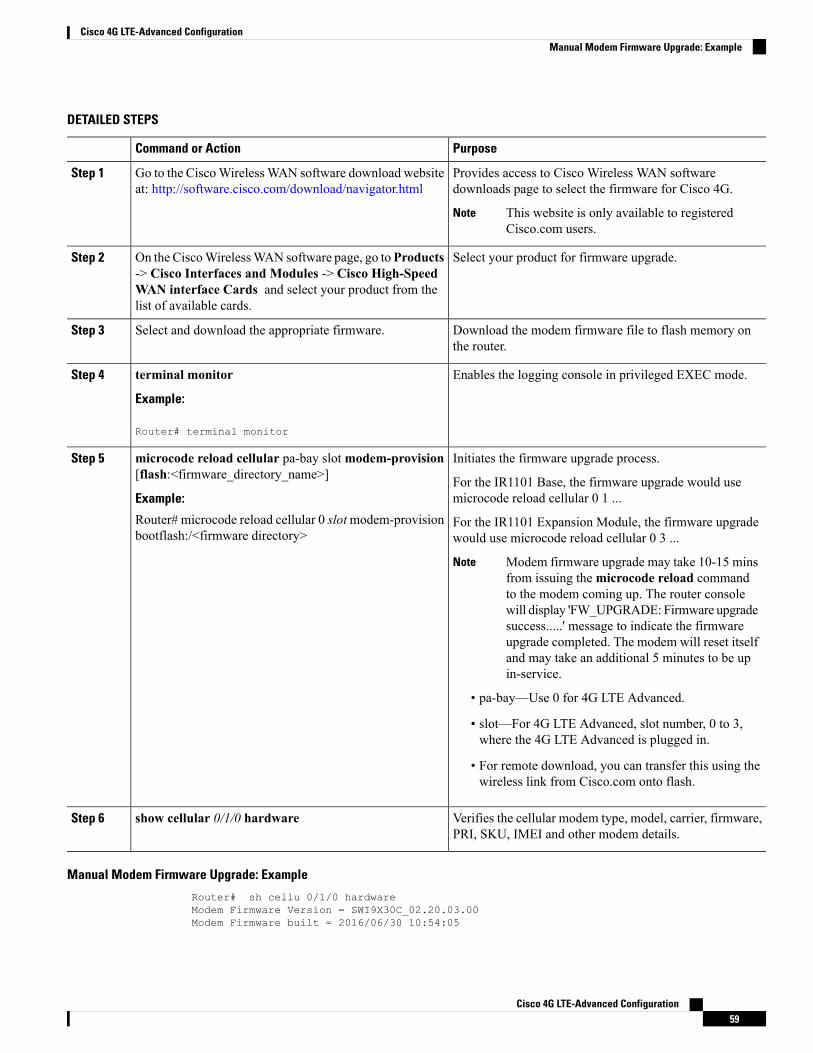
DETAILED STEPS
PurposeCommand or Action
Provides access to Cisco Wireless WAN softwaredownloads page to select the firmware for Cisco 4G.
Go to the CiscoWirelessWAN software download websiteat: http://software.cisco.com/download/navigator.html
Step 1
This website is only available to registeredCisco.com users.
Note
Select your product for firmware upgrade.On the CiscoWirelessWAN software page, go toProducts-> Cisco Interfaces and Modules -> Cisco High-Speed
Step 2
WAN interface Cards and select your product from thelist of available cards.
Download the modem firmware file to flash memory onthe router.
Select and download the appropriate firmware.Step 3
Enables the logging console in privileged EXEC mode.terminal monitor
Example:
Step 4
Router# terminal monitor
Initiates the firmware upgrade process.microcode reload cellular pa-bay slotmodem-provision[flash:<firmware_directory_name>]
Step 5
For the IR1101 Base, the firmware upgrade would usemicrocode reload cellular 0 1 ...Example:
Router# microcode reload cellular 0 slotmodem-provisionbootflash:/<firmware directory>
For the IR1101 Expansion Module, the firmware upgradewould use microcode reload cellular 0 3 ...
Modem firmware upgrade may take 10-15 minsfrom issuing themicrocode reload commandto the modem coming up. The router consolewill display 'FW_UPGRADE: Firmware upgradesuccess.....' message to indicate the firmwareupgrade completed. The modem will reset itselfand may take an additional 5 minutes to be upin-service.
Note
• pa-bay—Use 0 for 4G LTE Advanced.
• slot—For 4G LTE Advanced, slot number, 0 to 3,where the 4G LTE Advanced is plugged in.
• For remote download, you can transfer this using thewireless link from Cisco.com onto flash.
Verifies the cellular modem type, model, carrier, firmware,PRI, SKU, IMEI and other modem details.
show cellular 0/1/0 hardwareStep 6
Manual Modem Firmware Upgrade: Example
Router# sh cellu 0/1/0 hardwareModem Firmware Version = SWI9X30C_02.20.03.00Modem Firmware built = 2016/06/30 10:54:05
Cisco 4G LTE-Advanced Configuration59
Cisco 4G LTE-Advanced ConfigurationManual Modem Firmware Upgrade: Example
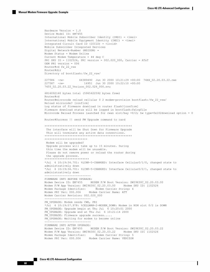
Hardware Version = 1.0Device Model ID: EM7455International Mobile Subscriber Identity (IMSI) = <imsi>International Mobile Equipment Identity (IMEI) = <imei>Integrated Circuit Card ID (ICCID) = <iccid>Mobile Subscriber Integrated ServicesDigital Network-Number (MSISDN) =Modem Status = Modem OnlineCurrent Modem Temperature = 44 deg CPRI SKU ID = 1102526, PRI version = 002.020_000, Carrier = AT&TOEM PRI version = 006Router#cd fw_22_vzwRouter#dirDirectory of bootflash:/fw_22_vzw/
227586 -rw- 64389490 Jun 30 2000 10:21:29 +00:00 74XX_02.20.03.22.cwe227587 -rw- 16951 Jun 30 2000 10:22:10 +00:007455_02.20.03.22_Verizon_002.026_000.nvu
6816092160 bytes total (5965422592 bytes free)Router#cdRouter#microcode reload cellular 0 2 modem-provision bootflash:/fw_22_vzw/Reload microcode? [confirm]Log status of firmware download in router flash?[confirm]Firmware download status will be logged in bootflash:fwlogfileMicrocode Reload Process launched for cwan slot/bay =0/2; hw type=0x102download option = 0
Router#Success !! send FW Upgrade command to card
*****************************************************The interface will be Shut Down for Firmware UpgradeThis will terminate any active data connections.*******************************************************************************Modem will be upgraded!Upgrade process will take up to 15 minutes. Duringthis time the modem will be unusable.Please do not remove power or reload the router duringthe upgrade process.****************************Jul 6 10:19:34.701: %LINK-5-CHANGED: Interface Cellular0/1/0, changed state toadministratively down*Jul 6 10:19:34.701: %LINK-5-CHANGED: Interface Cellular0/2/1, changed state toadministratively down----------------------------FIRMWARE INFO BEFORE UPGRADE:Modem Device ID: EM7455 MODEM F/W Boot Version: SWI9X30C_02.20.03.00Modem F/W App Version: SWI9X30C_02.20.03.00 Modem SKU ID: 1102526Modem Package Identifier: Modem Carrier String: 4Modem PRI Ver: 000.006 Modem Carrier Name: ATTModem Carrier Revision: 002.020_000----------------------------FW_UPGRADE: Modem needs CWE, PRI*Jul 6 10:19:57.978: %CELLWAN-2-MODEM_DOWN: Modem in NIM slot 0/2 is DOWNFW_UPGRADE: Upgrade begin at Thu Jul 6 10:20:01 2000FW_UPGRADE: Upgrade end at Thu Jul 6 10:21:14 2000FW_UPGRADE: Firmware upgrade success.....FW_UPGRADE: Waiting for modem to become online----------------------------FIRMWARE INFO AFTER UPGRADE:Modem Device ID: EM7455 MODEM F/W Boot Version: SWI9X30C_02.20.03.22Modem F/W App Version: SWI9X30C_02.20.03.22 Modem SKU ID: 1102526Modem Package Identifier: Modem Carrier String: 5Modem PRI Ver: 000.006 Modem Carrier Name: VERIZON
Cisco 4G LTE-Advanced Configuration60
Cisco 4G LTE-Advanced ConfigurationManual Modem Firmware Upgrade: Example
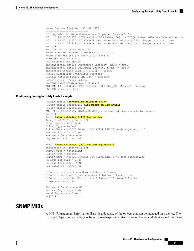
Modem Carrier Revision: 002.026_000----------------------------F/W Upgrade: Firmware Upgrade has Completed Successfully*Jul 6 10:21:55.275: %CELLWAN-2-MODEM_RADIO: Cellular0/1/0 Modem radio has been turned on*Jul 6 10:21:57.276: %LINK-3-UPDOWN: Interface Cellular0/1/0, changed state to down*Jul 6 10:21:57.277: %LINK-3-UPDOWN: Interface Cellular0/2/1, changed state to downRouter#Router# sh cellu 0/1/0 hardwareModem Firmware Version = SWI9X30C_02.20.03.22Modem Firmware built = 2016/10/11 16:03:14Hardware Version = 1.0Device Model ID: EM7455International Mobile Subscriber Identity (IMSI) =<imsi>International Mobile Equipment Identity (IMEI) = <imei>Integrated Circuit Card ID (ICCID) = <iccid>Mobile Subscriber Integrated ServicesDigital Network-Number (MSISDN) = <msisdn>Modem Status = Modem OnlineCurrent Modem Temperature = 0 deg CPRI SKU ID = 1102526, PRI version = 002.026_000, Carrier = VerizonOEM PRI version = 006
Configuring dm-log to Utility Flash: Example
Router(config)#controller cellular 0/1/0Router(config-controller)#lte modem dm-log enableRouter(config-controller)#*May 8 17:57:09.905: %SYS-5-CONFIG_I: Configured from console by consoleRouter#Router#show cellular 0/1/0 log dm-logIntegrated DM logging is offOutput path = bootflash:Filter Type = DefaultFilter Name = v11026_Generic_GSM_WCDMA_LTE_IP-no-data-packets.sqfMaximum log size = 0 MBMaximum file size = 0 MBLog rotation = Disabled
IR1101#show cellular 0/1/0 log dm-log detailsIntegrated DM logging is offOutput path = bootflash:Filter Type = DefaultFilter Name = v11026_Generic_GSM_WCDMA_LTE_IP-no-data-packets.sqfMaximum log size = 0 MBMaximum file size = 0 MBLog rotation = Disabled
0 Packets sent to the modem, 0 Bytes, 0 Errors0 Packets received from the modem, 0 Bytes, 0 Input drops0 Packets stored in file system, 0 Bytes, 0 Errors, 0 Aborts0 Max rcv queue size
Current file size = 0 MBCurrent log size = 0 MBTotal log size = 0 MBIR1101#
SNMP MIBsA MIB (Management Information Base) is a database of the objects that can be managed on a device. Themanaged objects, or variables, can be set or read to provide information on the network devices and interfaces.
Cisco 4G LTE-Advanced Configuration61
Cisco 4G LTE-Advanced ConfigurationConfiguring dm-log to Utility Flash: Example
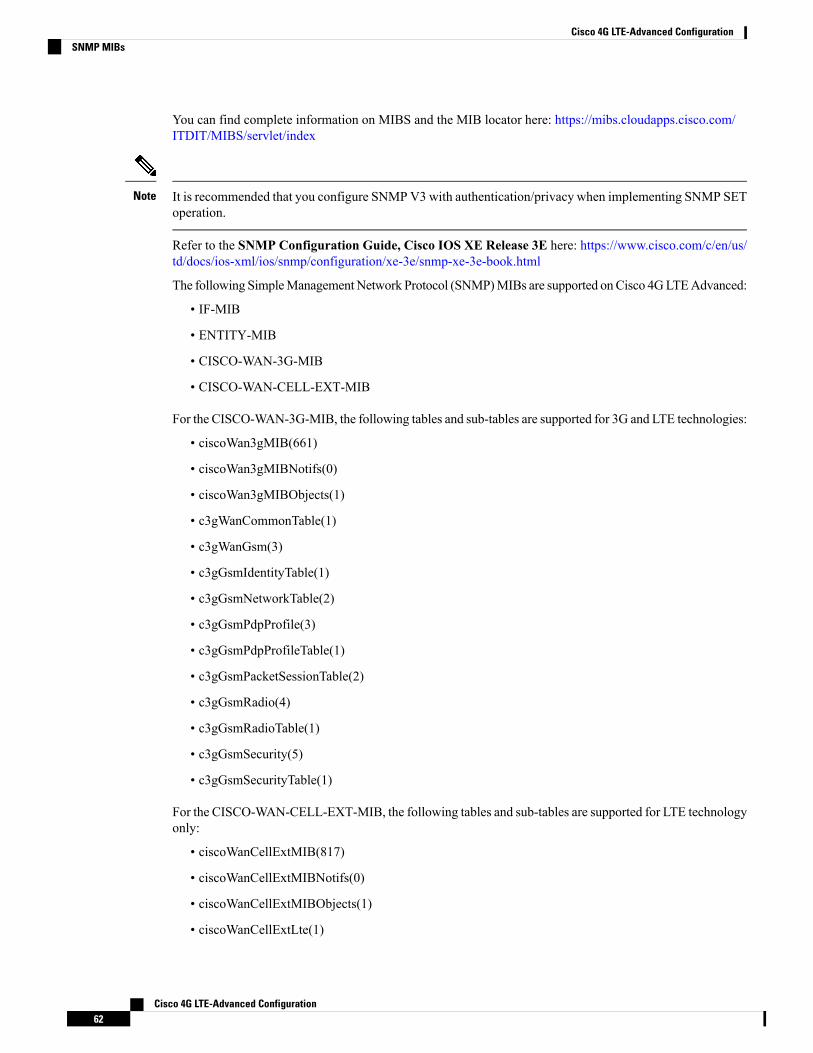
You can find complete information on MIBS and the MIB locator here: https://mibs.cloudapps.cisco.com/ITDIT/MIBS/servlet/index
It is recommended that you configure SNMPV3 with authentication/privacy when implementing SNMP SEToperation.
Note
Refer to the SNMP Configuration Guide, Cisco IOS XE Release 3E here: https://www.cisco.com/c/en/us/td/docs/ios-xml/ios/snmp/configuration/xe-3e/snmp-xe-3e-book.html
The following SimpleManagementNetwork Protocol (SNMP)MIBs are supported onCisco 4GLTEAdvanced:
• IF-MIB
• ENTITY-MIB
• CISCO-WAN-3G-MIB
• CISCO-WAN-CELL-EXT-MIB
For the CISCO-WAN-3G-MIB, the following tables and sub-tables are supported for 3G and LTE technologies:
• ciscoWan3gMIB(661)
• ciscoWan3gMIBNotifs(0)
• ciscoWan3gMIBObjects(1)
• c3gWanCommonTable(1)
• c3gWanGsm(3)
• c3gGsmIdentityTable(1)
• c3gGsmNetworkTable(2)
• c3gGsmPdpProfile(3)
• c3gGsmPdpProfileTable(1)
• c3gGsmPacketSessionTable(2)
• c3gGsmRadio(4)
• c3gGsmRadioTable(1)
• c3gGsmSecurity(5)
• c3gGsmSecurityTable(1)
For the CISCO-WAN-CELL-EXT-MIB, the following tables and sub-tables are supported for LTE technologyonly:
• ciscoWanCellExtMIB(817)
• ciscoWanCellExtMIBNotifs(0)
• ciscoWanCellExtMIBObjects(1)
• ciscoWanCellExtLte(1)
Cisco 4G LTE-Advanced Configuration62
Cisco 4G LTE-Advanced ConfigurationSNMP MIBs
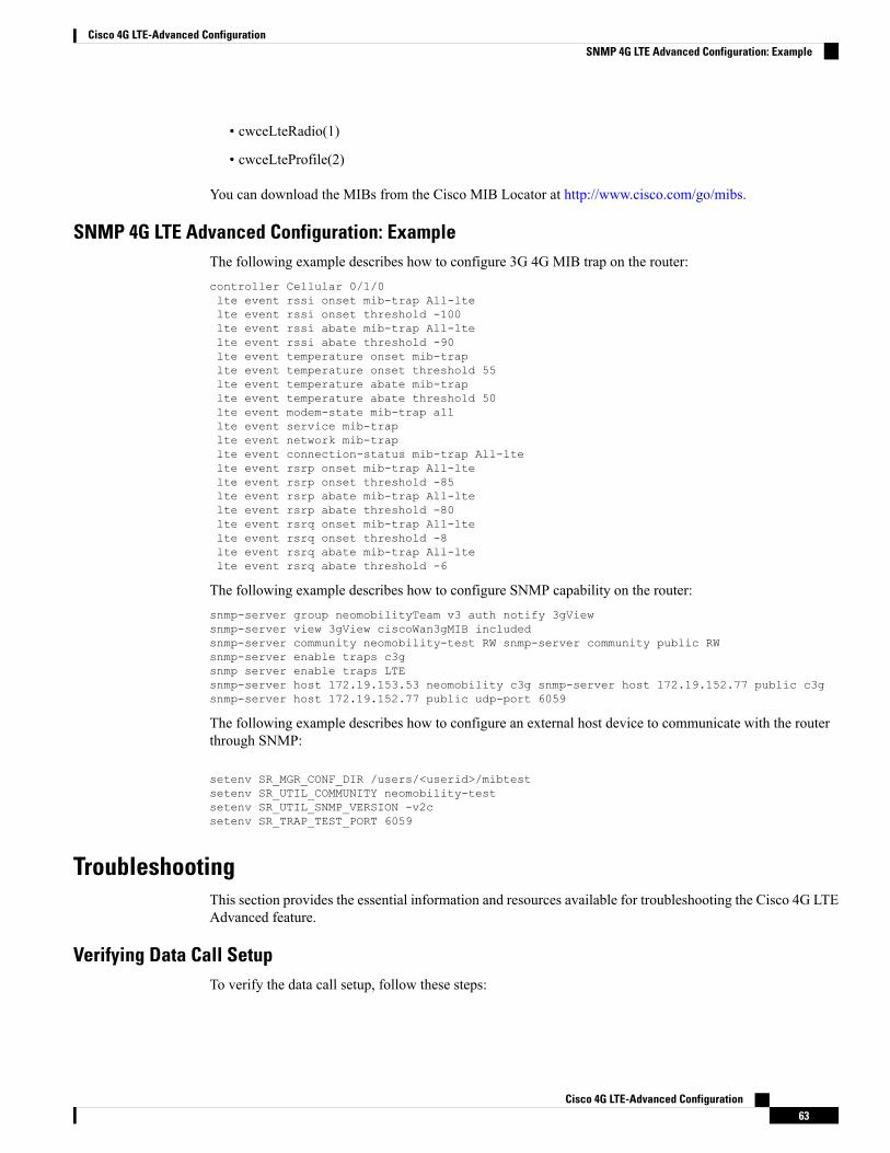
• cwceLteRadio(1)
• cwceLteProfile(2)
You can download the MIBs from the Cisco MIB Locator at http://www.cisco.com/go/mibs.
SNMP 4G LTE Advanced Configuration: ExampleThe following example describes how to configure 3G 4G MIB trap on the router:controller Cellular 0/1/0lte event rssi onset mib-trap All-ltelte event rssi onset threshold -100lte event rssi abate mib-trap All-ltelte event rssi abate threshold -90lte event temperature onset mib-traplte event temperature onset threshold 55lte event temperature abate mib-traplte event temperature abate threshold 50lte event modem-state mib-trap alllte event service mib-traplte event network mib-traplte event connection-status mib-trap All-ltelte event rsrp onset mib-trap All-ltelte event rsrp onset threshold -85lte event rsrp abate mib-trap All-ltelte event rsrp abate threshold -80lte event rsrq onset mib-trap All-ltelte event rsrq onset threshold -8lte event rsrq abate mib-trap All-ltelte event rsrq abate threshold -6
The following example describes how to configure SNMP capability on the router:snmp-server group neomobilityTeam v3 auth notify 3gViewsnmp-server view 3gView ciscoWan3gMIB includedsnmp-server community neomobility-test RW snmp-server community public RWsnmp-server enable traps c3gsnmp server enable traps LTEsnmp-server host 172.19.153.53 neomobility c3g snmp-server host 172.19.152.77 public c3gsnmp-server host 172.19.152.77 public udp-port 6059
The following example describes how to configure an external host device to communicate with the routerthrough SNMP:
setenv SR_MGR_CONF_DIR /users/<userid>/mibtestsetenv SR_UTIL_COMMUNITY neomobility-testsetenv SR_UTIL_SNMP_VERSION -v2csetenv SR_TRAP_TEST_PORT 6059
TroubleshootingThis section provides the essential information and resources available for troubleshooting the Cisco 4G LTEAdvanced feature.
Verifying Data Call SetupTo verify the data call setup, follow these steps:
Cisco 4G LTE-Advanced Configuration63
Cisco 4G LTE-Advanced ConfigurationSNMP 4G LTE Advanced Configuration: Example
1. After you create a modem data profile using the cellular profile create command and configuring DDRon the cellular interface, send a ping from the router to a host across the wireless network.
2. If the ping fails, debug the failure by using the following debug and show commands:
3. debug chat
4. debug modem
5. debug dialer
6. show cellular all
7. show controller cell0/1/0
8. show interface cellular
9. show running-config
10. show ip route
11. show platform
12. Save the output from these commands and contact your system administrator.
Checking Signal StrengthIf the Received Signal Strength Indication (RSSI) level is very low (for example, if it is less than –110 dBm),follow these steps:
SUMMARY STEPS
1. Ensure at least one antenna is connected to the 'MAIN' RF port on the 4G module. Preferably both MAINand DIV RF ports should be connected to antenna for better RF signal. Check to ensure the antenna arethreaded and tightened.
2. If you are using a remote antenna, move the antenna cradle and check if the RSSI has improved.3. Contact your wireless service provider to verify if there is service availability in your area.
DETAILED STEPS
PurposeCommand or Action
Ensure at least one antenna is connected to the 'MAIN' RFport on the 4G module. Preferably both MAIN and DIV
Step 1
RF ports should be connected to antenna for better RFsignal. Check to ensure the antenna are threaded andtightened.
If you are using a remote antenna, move the antenna cradleand check if the RSSI has improved.
Step 2
Contact your wireless service provider to verify if there isservice availability in your area.
Step 3
Cisco 4G LTE-Advanced Configuration64
Cisco 4G LTE-Advanced ConfigurationChecking Signal Strength
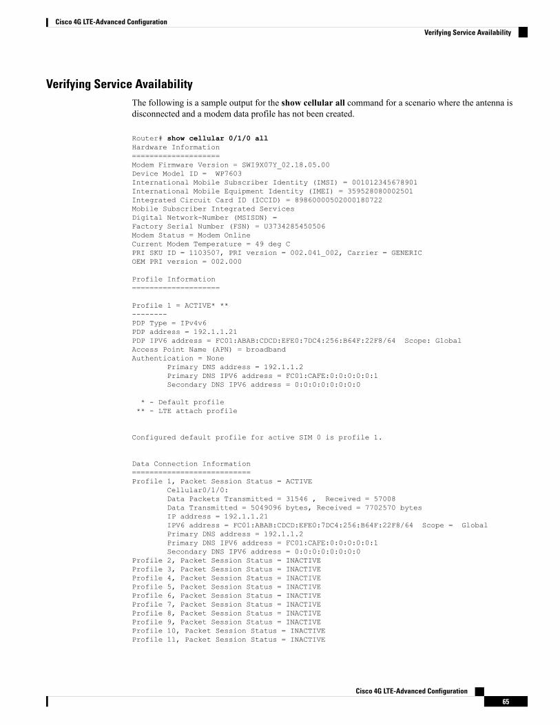
Verifying Service AvailabilityThe following is a sample output for the show cellular all command for a scenario where the antenna isdisconnected and a modem data profile has not been created.
Router# show cellular 0/1/0 allHardware Information====================Modem Firmware Version = SWI9X07Y_02.18.05.00Device Model ID = WP7603International Mobile Subscriber Identity (IMSI) = 001012345678901International Mobile Equipment Identity (IMEI) = 359528080002501Integrated Circuit Card ID (ICCID) = 89860000502000180722Mobile Subscriber Integrated ServicesDigital Network-Number (MSISDN) =Factory Serial Number (FSN) = U3734285450506Modem Status = Modem OnlineCurrent Modem Temperature = 49 deg CPRI SKU ID = 1103507, PRI version = 002.041_002, Carrier = GENERICOEM PRI version = 002.000
Profile Information====================
Profile 1 = ACTIVE* **--------PDP Type = IPv4v6PDP address = 192.1.1.21PDP IPV6 address = FC01:ABAB:CDCD:EFE0:7DC4:256:B64F:22F8/64 Scope: GlobalAccess Point Name (APN) = broadbandAuthentication = None
Primary DNS address = 192.1.1.2Primary DNS IPV6 address = FC01:CAFE:0:0:0:0:0:1Secondary DNS IPV6 address = 0:0:0:0:0:0:0:0
* - Default profile** - LTE attach profile
Configured default profile for active SIM 0 is profile 1.
Data Connection Information===========================Profile 1, Packet Session Status = ACTIVE
Cellular0/1/0:Data Packets Transmitted = 31546 , Received = 57008Data Transmitted = 5049096 bytes, Received = 7702570 bytesIP address = 192.1.1.21IPV6 address = FC01:ABAB:CDCD:EFE0:7DC4:256:B64F:22F8/64 Scope = GlobalPrimary DNS address = 192.1.1.2Primary DNS IPV6 address = FC01:CAFE:0:0:0:0:0:1Secondary DNS IPV6 address = 0:0:0:0:0:0:0:0
Profile 2, Packet Session Status = INACTIVEProfile 3, Packet Session Status = INACTIVEProfile 4, Packet Session Status = INACTIVEProfile 5, Packet Session Status = INACTIVEProfile 6, Packet Session Status = INACTIVEProfile 7, Packet Session Status = INACTIVEProfile 8, Packet Session Status = INACTIVEProfile 9, Packet Session Status = INACTIVEProfile 10, Packet Session Status = INACTIVEProfile 11, Packet Session Status = INACTIVE
Cisco 4G LTE-Advanced Configuration65
Cisco 4G LTE-Advanced ConfigurationVerifying Service Availability
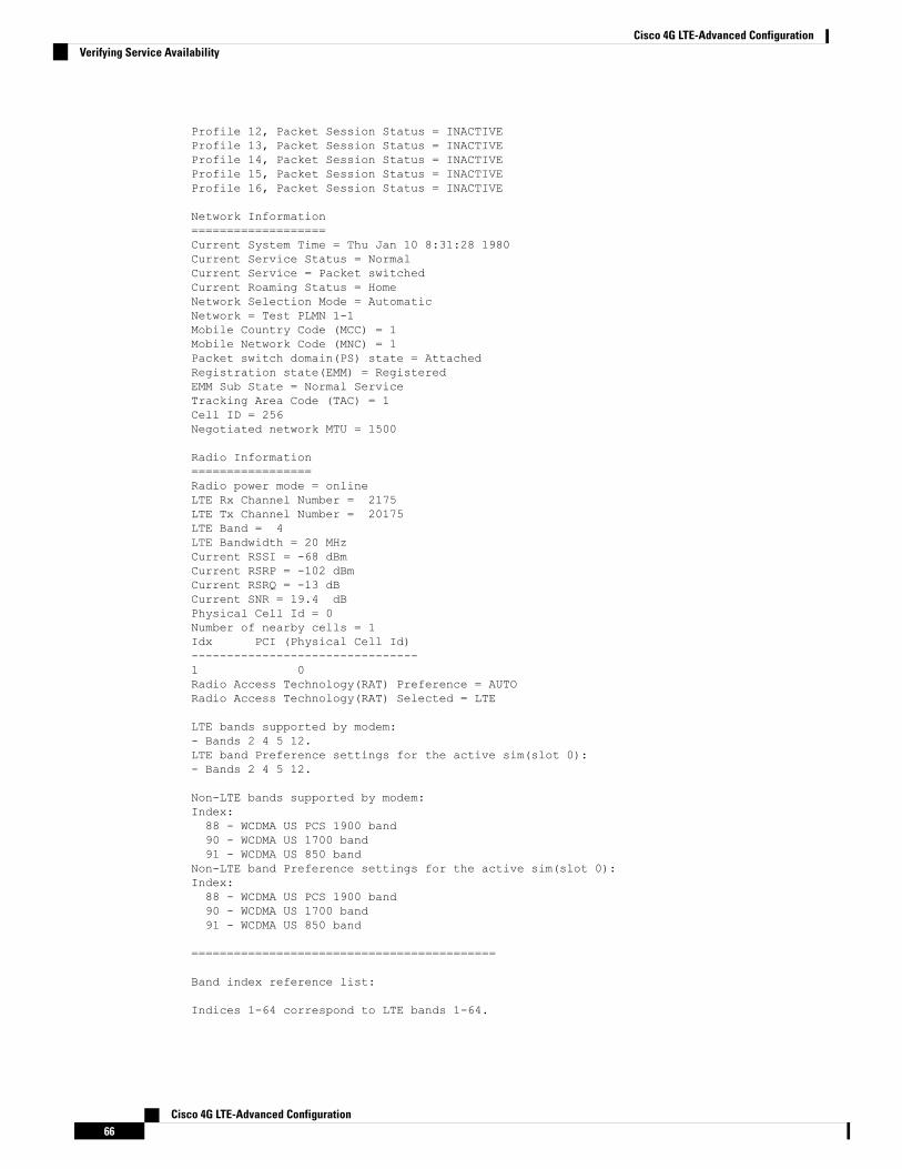
Profile 12, Packet Session Status = INACTIVEProfile 13, Packet Session Status = INACTIVEProfile 14, Packet Session Status = INACTIVEProfile 15, Packet Session Status = INACTIVEProfile 16, Packet Session Status = INACTIVE
Network Information===================Current System Time = Thu Jan 10 8:31:28 1980Current Service Status = NormalCurrent Service = Packet switchedCurrent Roaming Status = HomeNetwork Selection Mode = AutomaticNetwork = Test PLMN 1-1Mobile Country Code (MCC) = 1Mobile Network Code (MNC) = 1Packet switch domain(PS) state = AttachedRegistration state(EMM) = RegisteredEMM Sub State = Normal ServiceTracking Area Code (TAC) = 1Cell ID = 256Negotiated network MTU = 1500
Radio Information=================Radio power mode = onlineLTE Rx Channel Number = 2175LTE Tx Channel Number = 20175LTE Band = 4LTE Bandwidth = 20 MHzCurrent RSSI = -68 dBmCurrent RSRP = -102 dBmCurrent RSRQ = -13 dBCurrent SNR = 19.4 dBPhysical Cell Id = 0Number of nearby cells = 1Idx PCI (Physical Cell Id)--------------------------------1 0Radio Access Technology(RAT) Preference = AUTORadio Access Technology(RAT) Selected = LTE
LTE bands supported by modem:- Bands 2 4 5 12.LTE band Preference settings for the active sim(slot 0):- Bands 2 4 5 12.
Non-LTE bands supported by modem:Index:88 - WCDMA US PCS 1900 band90 - WCDMA US 1700 band91 - WCDMA US 850 band
Non-LTE band Preference settings for the active sim(slot 0):Index:88 - WCDMA US PCS 1900 band90 - WCDMA US 1700 band91 - WCDMA US 850 band
===========================================
Band index reference list:
Indices 1-64 correspond to LTE bands 1-64.
Cisco 4G LTE-Advanced Configuration66
Cisco 4G LTE-Advanced ConfigurationVerifying Service Availability
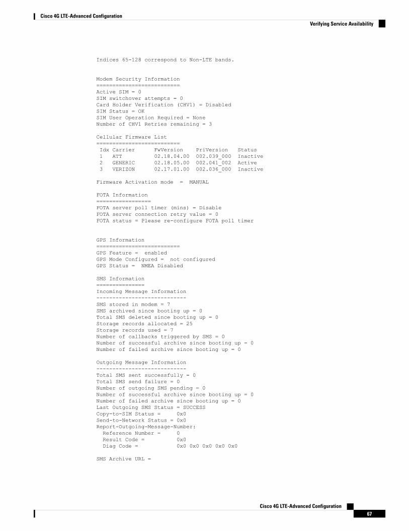
Indices 65-128 correspond to Non-LTE bands.
Modem Security Information==========================Active SIM = 0SIM switchover attempts = 0Card Holder Verification (CHV1) = DisabledSIM Status = OKSIM User Operation Required = NoneNumber of CHV1 Retries remaining = 3
Cellular Firmware List==========================Idx Carrier FwVersion PriVersion Status1 ATT 02.18.04.00 002.039_000 Inactive2 GENERIC 02.18.05.00 002.041_002 Active3 VERIZON 02.17.01.00 002.036_000 Inactive
Firmware Activation mode = MANUAL
FOTA Information=================FOTA server poll timer (mins) = DisableFOTA server connection retry value = 0FOTA status = Please re-configure FOTA poll timer
GPS Information==========================GPS Feature = enabledGPS Mode Configured = not configuredGPS Status = NMEA Disabled
SMS Information===============Incoming Message Information----------------------------SMS stored in modem = 7SMS archived since booting up = 0Total SMS deleted since booting up = 0Storage records allocated = 25Storage records used = 7Number of callbacks triggered by SMS = 0Number of successful archive since booting up = 0Number of failed archive since booting up = 0
Outgoing Message Information----------------------------Total SMS sent successfully = 0Total SMS send failure = 0Number of outgoing SMS pending = 0Number of successful archive since booting up = 0Number of failed archive since booting up = 0Last Outgoing SMS Status = SUCCESSCopy-to-SIM Status = 0x0Send-to-Network Status = 0x0Report-Outgoing-Message-Number:Reference Number = 0Result Code = 0x0Diag Code = 0x0 0x0 0x0 0x0 0x0
SMS Archive URL =
Cisco 4G LTE-Advanced Configuration67
Cisco 4G LTE-Advanced ConfigurationVerifying Service Availability
Modem Crashdump Information===========================Modem crashdump logging = off
Successful Call SetupThe following is a sample output when a call is set up. It shows a received IP address from the network. Callsetup is successful and data path is open.
debug cellular 0/1/0 messages callcontrol
Modem Troubleshooting Using Integrated Modem DM LoggingAs part of the 3G and 4G serviceability enhancement in Cisco IOS, DM log collection has been integratedinto Cisco IOS, eliminating the need for an external PC and simplifying the DM log collection process. Thelte modem dm-log command can be used in controller cellular configuration mode to configure integratedDM logging to monitor traffic on the modem. See the Cisco 3G and 4G Serviceability Enhancement UserGuide for more information on configuring Integrated DM Logging parameters.
Modem Settings for North America and Carriers Operating on 700 MHz BandFor LTE-EA deployments in North America and for carriers operating in the 700 MHz band, the followingchanges to the modem settings are required to prevent long network attach times.
The output of show cellular 0/1/0 all command shows the following:
• Current RSSI is –125 dBM
• LTE Technology Preference = No preference specified (AUTO)
The following sections explain useful commands for changing modem settings:
Changing Modem Settings
To change the modem settings to force the modem to scan different technologies, use the following CiscoIOS command:
Router# cellular 0/1/0 lte technology ?auto Automatic LTE Technology Selectionlte LTEumts UMTS
Electronic Serial Number (ESN)
The ESN number is located directly on the modem label in hexadecimal notation. It can also be retrievedusing the Cisco IOS CLI using the show cellular slot/port/module hardware command.
The sample output below shows the ESN number:
Hardware Information====================Electronic Serial Number (ESN) = 0x603c9854 [09603971156]Electronic Serial Number (ESN) = <specific ESN in hexadecimal> [specific ESN in decimal]
Cisco 4G LTE-Advanced Configuration68
Cisco 4G LTE-Advanced ConfigurationSuccessful Call Setup