Embed Size (px)
Citation preview

Cisco Connected Grid Router 2010 Software Configuration Guide First Published: 2010-05-27Last Updated: 2017-10-25THE SPECIFICATIONS AND INFORMATION REGARDING THE PRODUCTS IN THIS MANUAL ARE SUBJECT TO CHANGE WITHOUT NOTICE. ALL STATEMENTS, INFORMATION, AND RECOMMENDATIONS IN THIS MANUAL ARE BELIEVED TO BE ACCURATE BUT ARE PRESENTED WITHOUT WARRANTY OF ANY KIND, EXPRESS OR IMPLIED. USERS MUST TAKE FULL RESPONSIBILITY FOR THEIR APPLICATION OF ANY PRODUCTS.THE SOFTWARE LICENSE AND LIMITED WARRANTY FOR THE ACCOMPANYING PRODUCT ARE INCORPORATED HEREIN BY THIS REFERENCE. IF YOU ARE UNABLE TO LOCATE THE SOFTWARE LICENSE OR LIMITED WARRANTY, CONTACT YOUR CISCO REPRESENTATIVE FOR A COPY.The Cisco implementation of TCP header compression is an adaptation of a program developed by the University of California, Berkeley (UCB) as part of UCB’s public domain version of the UNIX operating system. All rights reserved. Copyright © 1981, Regents of the University of California. NOTWITHSTANDING ANY OTHER WARRANTY HEREIN, ALL DOCUMENT FILES AND SOFTWARE OF THESE SUPPLIERS ARE PROVIDED “AS IS” WITH ALL FAULTS. CISCO AND THE ABOVE-NAMED SUPPLIERS DISCLAIM ALL WARRANTIES, EXPRESSED OR IMPLIED, INCLUDING, WITHOUT LIMITATION, THOSE OF MERCHANTABILITY, FITNESS FOR A PARTICULAR PURPOSE AND NONINFRINGEMENT OR ARISING FROM A COURSE OF DEALING, USAGE, OR TRADE PRACTICE.IN NO EVENT SHALL CISCO OR ITS SUPPLIERS BE LIABLE FOR ANY INDIRECT, SPECIAL, CONSEQUENTIAL, OR INCIDENTAL DAMAGES, INCLUDING, WITHOUT LIMITATION, LOST PROFITS OR LOSS OR DAMAGE TO DATA ARISING OUT OF THE USE OR INABILITY TO USE THIS MANUAL, EVEN IF CISCO OR ITS SUPPLIERS HAVE BEEN ADVISED OF THE POSSIBILITY OF SUCH DAMAGES.
Cisco Systems, Inc. www.cisco.com

Any Internet Protocol (IP) addresses and phone numbers used in this document are not intended to be actual addresses and phone numbers. Any examples, command display output, network topology diagrams, and other figures included in the document are shown for illustrative purposes only. Any use of actual IP addresses or phone numbers in illustrative content is unintentional and coincidental.All printed copies and duplicate soft copies are considered un-Controlled copies and the original on-line version should be referred to for latest version.Cisco has more than 200 offices worldwide. Addresses, phone numbers, and fax numbers are listed on the Cisco website at www.cisco.com/go/offices.Cisco and the Cisco logo are trademarks or registered trademarks of Cisco and/or its affiliates in the U.S. and other countries. To view a list of Cisco trademarks, go to this URL:www.cisco.com/go/trademarks. Third-party trademarks mentioned are the property of their respective owners. The use of the word partner does not imply a partnership relationshipbetween Cisco and any other company. (1721R)
© 2010–2017 Cisco Systems, Inc. All rights reserved.
2
Preface
First Published: May 27, 2010, OL-20356-01Last Updated: October 25, 2017
OrganizationThe document organization is described in the following table:
1 Overview of the Hardware and Software
Describes new hardware and software features in this release, features by platform, new slots, common ports, and getting started tasks.
2 Setup for Initial Configuration Describes how to perform the initial configuration of the router using the Cisco Setup command facility, verifying the initial configuration, and completing the configuration.
3 Cisco IOS CLI for Initial Configuration
Describes how to perform the initial configuration of the router using the Cisco IOS command-line interface (CLI), and additional configuration procedures for the router.
4 Basic Router Configuration Describes how to perform the basic router configuration, interface configuration, and routing configuration.
5 Configuring Backup Data Lines and Remote Management
Describes how to configure backup interfaces, configure dial backup, and remote management.
6 Upgrading the Cisco IOS Software Describes how to upgrade the Cisco IOS software image on the router or the access point.
7 Using CompactFlash Memory Describes how to use Advanced Capability CompactFlash (CF) memory cards on the router.
8 Using ROM Monitor Describes how to use the ROM monitor to manually load a system image, upgrade the system image when there are no TFTP servers or network connections, or for disaster recovery.
9 Changing the Configuration Register Settings
Describes the 16-bit configuration register in NVRAM and how to make changes to the register settings using the Cisco IOS CLI.
1Cisco Connected Grid Router 2010 Software Configuration Guide
OL-20356-01
PrefaceConventions
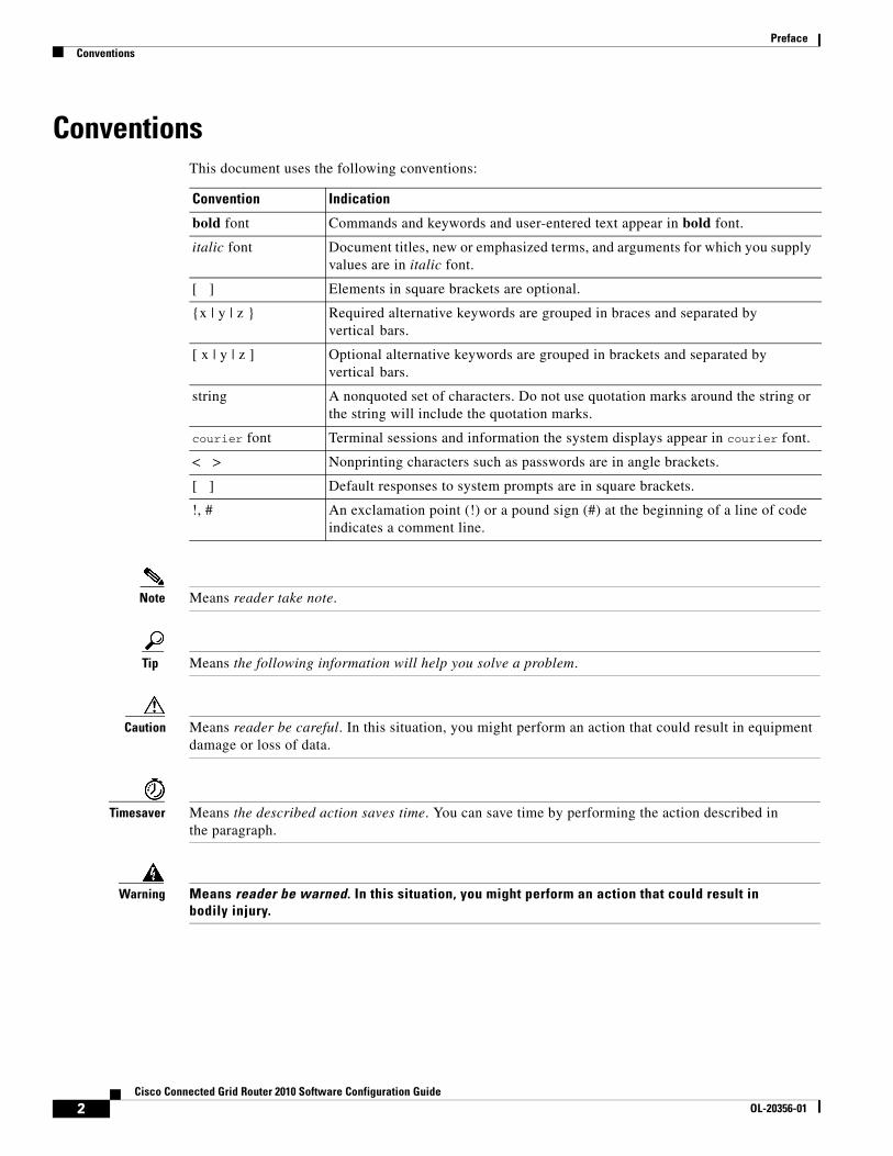
ConventionsThis document uses the following conventions:
Note Means reader take note.
Tip Means the following information will help you solve a problem.
Caution Means reader be careful. In this situation, you might perform an action that could result in equipment damage or loss of data.
Timesaver Means the described action saves time. You can save time by performing the action described in the paragraph.
Warning Means reader be warned. In this situation, you might perform an action that could result in bodily injury.
Convention Indication
bold font Commands and keywords and user-entered text appear in bold font.
italic font Document titles, new or emphasized terms, and arguments for which you supply values are in italic font.
[ ] Elements in square brackets are optional.
{x | y | z } Required alternative keywords are grouped in braces and separated by vertical bars.
[ x | y | z ] Optional alternative keywords are grouped in brackets and separated by vertical bars.
string A nonquoted set of characters. Do not use quotation marks around the string or the string will include the quotation marks.
courier font Terminal sessions and information the system displays appear in courier font.
< > Nonprinting characters such as passwords are in angle brackets.
[ ] Default responses to system prompts are in square brackets.
!, # An exclamation point (!) or a pound sign (#) at the beginning of a line of code indicates a comment line.
2Cisco Connected Grid Router 2010 Software Configuration Guide
OL-20356-01
Overview of the Hardware and Software
First Published: May 27, 2010, OL-20356-01Last Updated: October 25, 2017
The Cisco Connected Grid Router 2010 (Cisco CGR 2010) router is a member of the Cisco Connected Grid Router 2000 Series family of routers. The Cisco CGR 2010 router is designed to run in the extreme and demanding power substation environment. It is an especially rugged, high-performance router that provides LAN and WAN connectivity, field replaceable parts, and feature upgrades through software licensing. The Cisco CGR 2010 router is designed to withstand hostile environments while continuing to deliver the performance, availability, and reliability to scale mission-critical needs.
Audience
The Cisco IOS software documentation set is intended primarily for users who configure and maintain Cisco networking devices (such as routers and switches) but who may not be familiar with the tasks, the relationship between tasks, or the Cisco IOS software commands necessary to perform particular tasks. The Cisco IOS software documentation set is also intended for those users experienced with Cisco IOS software who need to know about new features, new configuration options, and new software characteristics in the current Cisco IOS software release.
The Cisco Connected Grid Router 2010 router is described in the following sections.
• New Features in this Release, page 2
• Features by Platform, page 3
• Platform Description, page 3
• Common Ports, page 4
• Activating the Cisco Software License, page 4
• Getting Started, page 4
Note This document is written for experienced technical workers who install, monitor, and troubleshoot routers under a service contract, or who work for an information technology (IT) department.
Americas Headquarters:Cisco Systems, Inc., 170 West Tasman Drive, San Jose, CA 95134-1706 USA
© 2010 Cisco Systems, Inc. All rights reserved.
Overview of the Hardware and SoftwareNew Features in this Release
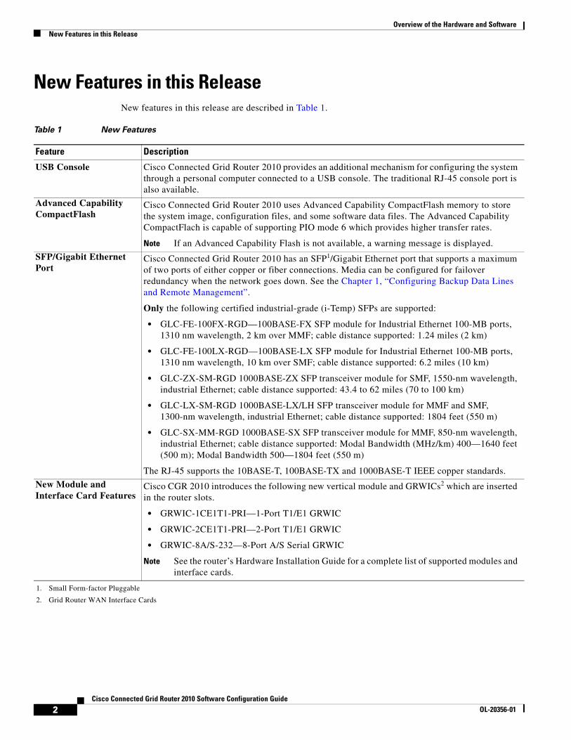
New Features in this ReleaseNew features in this release are described in Table 1.
Table 1 New Features
Feature Description
USB Console Cisco Connected Grid Router 2010 provides an additional mechanism for configuring the system through a personal computer connected to a USB console. The traditional RJ-45 console port is also available.
Advanced Capability CompactFlash
Cisco Connected Grid Router 2010 uses Advanced Capability CompactFlash memory to store the system image, configuration files, and some software data files. The Advanced Capability CompactFlach is capable of supporting PIO mode 6 which provides higher transfer rates.
Note If an Advanced Capability Flash is not available, a warning message is displayed.
SFP/Gigabit Ethernet Port
Cisco Connected Grid Router 2010 has an SFP1/Gigabit Ethernet port that supports a maximum of two ports of either copper or fiber connections. Media can be configured for failover redundancy when the network goes down. See the Chapter 1, “Configuring Backup Data Lines and Remote Management”.
Only the following certified industrial-grade (i-Temp) SFPs are supported:
• GLC-FE-100FX-RGD—100BASE-FX SFP module for Industrial Ethernet 100-MB ports, 1310 nm wavelength, 2 km over MMF; cable distance supported: 1.24 miles (2 km)
• GLC-FE-100LX-RGD—100BASE-LX SFP module for Industrial Ethernet 100-MB ports, 1310 nm wavelength, 10 km over SMF; cable distance supported: 6.2 miles (10 km)
• GLC-ZX-SM-RGD 1000BASE-ZX SFP transceiver module for SMF, 1550-nm wavelength, industrial Ethernet; cable distance supported: 43.4 to 62 miles (70 to 100 km)
• GLC-LX-SM-RGD 1000BASE-LX/LH SFP transceiver module for MMF and SMF, 1300-nm wavelength, industrial Ethernet; cable distance supported: 1804 feet (550 m)
• GLC-SX-MM-RGD 1000BASE-SX SFP transceiver module for MMF, 850-nm wavelength, industrial Ethernet; cable distance supported: Modal Bandwidth (MHz/km) 400—1640 feet (500 m); Modal Bandwidth 500—1804 feet (550 m)
The RJ-45 supports the 10BASE-T, 100BASE-TX and 1000BASE-T IEEE copper standards.
1. Small Form-factor Pluggable
New Module and Interface Card Features
Cisco CGR 2010 introduces the following new vertical module and GRWICs2 which are inserted in the router slots.
• GRWIC-1CE1T1-PRI—1-Port T1/E1 GRWIC
• GRWIC-2CE1T1-PRI—2-Port T1/E1 GRWIC
• GRWIC-8A/S-232—8-Port A/S Serial GRWIC
Note See the router’s Hardware Installation Guide for a complete list of supported modules and interface cards.
2. Grid Router WAN Interface Cards
2Cisco Connected Grid Router 2010 Software Configuration Guide
OL-20356-01
Overview of the Hardware and SoftwareFeatures by Platform
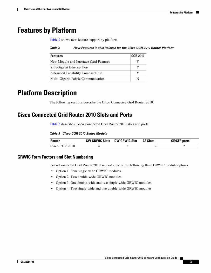
Features by PlatformTable 2 shows new feature support by platform.
Platform DescriptionThe following sections describe the Cisco Connected Grid Router 2010.
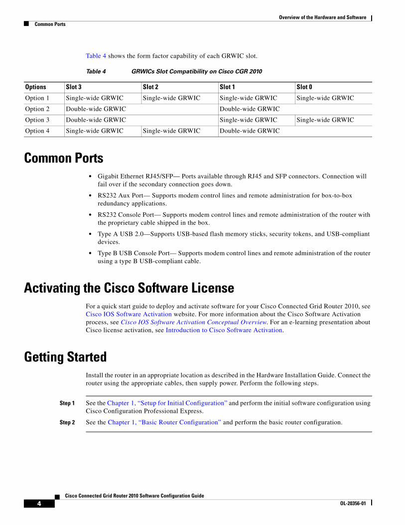
Cisco Connected Grid Router 2010 Slots and PortsTable 3 describes Cisco Connected Grid Router 2010 slots and ports.
Table 3 Cisco CGR 2010 Series Models
GRWIC Form Factors and Slot Numbering
Cisco Connected Grid Router 2010 supports one of the following three GRWIC module options:
• Option 1: Four single-wide GRWIC modules
• Option 2: Two double-wide GRWIC modules
• Option 3: One double-wide and two single-wide GRWIC modules
• Option 4: Two single-wide and one double-wide GRWIC modules
Table 2 New Features in this Release for the Cisco CGR 2010 Router Platform
Features CGR 2010
New Module and Interface Card Features Y
SFP/Gigabit Ethernet Port Y
Advanced Capability CompactFlash Y
Multi-Gigabit Fabric Communication N
Router SW GRWIC Slots DW GRWIC Slot CF Slots GE/SFP ports
Cisco CGR 2010 4 2 2 2
3Cisco Connected Grid Router 2010 Software Configuration Guide
OL-20356-01
Overview of the Hardware and SoftwareCommon Ports
Table 4 shows the form factor capability of each GRWIC slot.
Common Ports• Gigabit Ethernet RJ45/SFP— Ports available through RJ45 and SFP connectors. Connection will
fail over if the secondary connection goes down.
• RS232 Aux Port— Supports modem control lines and remote administration for box-to-box redundancy applications.
• RS232 Console Port— Supports modem control lines and remote administration of the router with the proprietary cable shipped in the box.
• Type A USB 2.0—Supports USB-based flash memory sticks, security tokens, and USB-compliant devices.
• Type B USB Console Port— Supports modem control lines and remote administration of the router using a type B USB-compliant cable.
Activating the Cisco Software LicenseFor a quick start guide to deploy and activate software for your Cisco Connected Grid Router 2010, see Cisco IOS Software Activation website. For more information about the Cisco Software Activation process, see Cisco IOS Software Activation Conceptual Overview. For an e-learning presentation about Cisco license activation, see Introduction to Cisco Software Activation.
Getting StartedInstall the router in an appropriate location as described in the Hardware Installation Guide. Connect the router using the appropriate cables, then supply power. Perform the following steps.
Step 1 See the Chapter 1, “Setup for Initial Configuration” and perform the initial software configuration using Cisco Configuration Professional Express.
Step 2 See the Chapter 1, “Basic Router Configuration” and perform the basic router configuration.
Table 4 GRWICs Slot Compatibility on Cisco CGR 2010
Options Slot 3 Slot 2 Slot 1 Slot 0
Option 1 Single-wide GRWIC Single-wide GRWIC Single-wide GRWIC Single-wide GRWIC
Option 2 Double-wide GRWIC Double-wide GRWIC
Option 3 Double-wide GRWIC Single-wide GRWIC Single-wide GRWIC
Option 4 Single-wide GRWIC Single-wide GRWIC Double-wide GRWIC
4Cisco Connected Grid Router 2010 Software Configuration Guide
OL-20356-01

Setup for Initial Configuration
First Published: May 27, 2010, OL-20356-01Last Updated: October 25, 2017
This module describes how to perform the initial configuration on the Cisco Connected Grid Router 2010 using the Cisco Setup command facility. However, we recommend using Cisco Configuration Professional Express (Cisco CPE). Cisco CPE is a web-based graphical-user interface that lets you perform the initial configuration.
For cross-platform system requirements, feature support, memory recommendations, platform-specific information, new and changed information, and other information related to Cisco IOS Release 15.1T, see Release Notes for Cisco IOS Release 15.1T.
Contents• Cisco Configuration Professional, page 5
• Cisco Setup Command Facility, page 6
• Verifying the Initial Configuration, page 9
• Completing the Configuration, page 9
Cisco Configuration ProfessionalAfter you connect cables and supply power to the router, download and use the Cisco Configuration Professional (Cisco CP) or Cisco CPE web-based application to configure the initial router settings.
Cisco Configuration Professional
Cisco CP is a GUI-based device management tool that allows you to configure Cisco IOS-based access routers, including Cisco Connected Grid Router 2010 routers. Cisco CP simplifies router, security, unified communications, wireless, WAN, and basic LAN configuration through GUI-based, easy-to-use wizards. Cisco CP is installed on a PC. See Cisco Configuration Professional Quick Start Guide for detailed Cisco CP installation instructions.
For instructions on using the Cisco CP, see the Cisco CP online help.
Americas Headquarters:Cisco Systems, Inc., 170 West Tasman Drive, San Jose, CA 95134-1706 USA
© 2010 Cisco Systems, Inc. All rights reserved.
Setup for Initial ConfigurationCisco Setup Command Facility
Cisco Configuration Professional Express
Cisco CP Express is a light weight version of Cisco CP. You can use Cisco CP Express to configure basic security features on the router's LAN and WAN interfaces. Cisco CP Express is available on the router Flash memory. See the Cisco CP Express online help for detailed instructions.
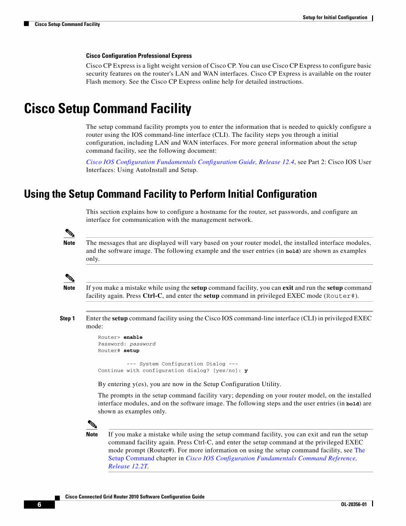
Cisco Setup Command FacilityThe setup command facility prompts you to enter the information that is needed to quickly configure a router using the IOS command-line interface (CLI). The facility steps you through a initial configuration, including LAN and WAN interfaces. For more general information about the setup command facility, see the following document:
Cisco IOS Configuration Fundamentals Configuration Guide, Release 12.4, see Part 2: Cisco IOS User Interfaces: Using AutoInstall and Setup.
Using the Setup Command Facility to Perform Initial ConfigurationThis section explains how to configure a hostname for the router, set passwords, and configure an interface for communication with the management network.
Note The messages that are displayed will vary based on your router model, the installed interface modules, and the software image. The following example and the user entries (in bold) are shown as examples only.
Note If you make a mistake while using the setup command facility, you can exit and run the setup command facility again. Press Ctrl-C, and enter the setup command in privileged EXEC mode (Router#).
Step 1 Enter the setup command facility using the Cisco IOS command-line interface (CLI) in privileged EXEC mode:
Router> enable Password: passwordRouter# setup
--- System Configuration Dialog ---Continue with configuration dialog? [yes/no]: y
By entering y(es), you are now in the Setup Configuration Utility.
The prompts in the setup command facility vary; depending on your router model, on the installed interface modules, and on the software image. The following steps and the user entries (in bold) are shown as examples only.
Note If you make a mistake while using the setup command facility, you can exit and run the setup command facility again. Press Ctrl-C, and enter the setup command at the privileged EXEC mode prompt (Router#). For more information on using the setup command facility, see The Setup Command chapter in Cisco IOS Configuration Fundamentals Command Reference, Release 12.2T.
6Cisco Connected Grid Router 2010 Software Configuration Guide
OL-20356-01

Setup for Initial ConfigurationCisco Setup Command Facility
Step 2 To proceed using the setup command facility, enter yes.
Continue with configuration dialog? [yes/no]: yes
At any point you may enter a question mark '?' for help.Use ctrl-c to abort configuration dialog at any prompt.Default settings are in square brackets '[]'.
Basic management setup configures only enough connectivityfor management of the system, extended setup will ask youto configure each interface on the system
Step 3 Basic management setup configures only enough connectivity.
Would you like to enter basic management setup? [yes/no]: yes
Step 4 Enter a hostname for the router (this example uses myrouter):
Configuring global parameters:Enter host name [Router]: myrouter
Step 5 Enter an enable secret password. This password is encrypted (for more security) and cannot be seen when viewing the configuration.
The enable secret is a password used to protect access toprivileged EXEC and configuration modes. This password, afterentered, becomes encrypted in the configuration.Enter enable secret: cisco
Step 6 Enter an enable password that is different from the enable secret password. This password is not encrypted (and is less secure) and can be seen when viewing the configuration.
The enable password is used when you do not specify anenable secret password, with some older software versions, andsome boot images.Enter enable password: cisco123
Step 7 Enter the virtual terminal password, which prevents unauthenticated access to the router through ports other than the console port:
The virtual terminal password is used to protectaccess to the router over a network interface.Enter virtual terminal password: cisco
Step 8 Respond to the following prompts as appropriate for your network:
Configure SNMP Network Management? [no]: yes Community string [public]:
A summary of the available interfaces is displayed.
Note The interface summary includes interface numbering, which is dependent on the router model and the installed modules and interface cards.
Current interface summary
Interface IP-Address OK? Method Status ProlGigabitEthernet0/0 192.168.1.2 YES NVRAM administratively down dow GigabitEthernet0/1 unassigned YES NVRAM up up Serial0/0/1 unassigned YES NVRAM administratively down dow Serial0/0/2 unassigned YES NVRAM administratively down dow
7Cisco Connected Grid Router 2010 Software Configuration Guide
OL-20356-01
Setup for Initial ConfigurationCisco Setup Command Facility
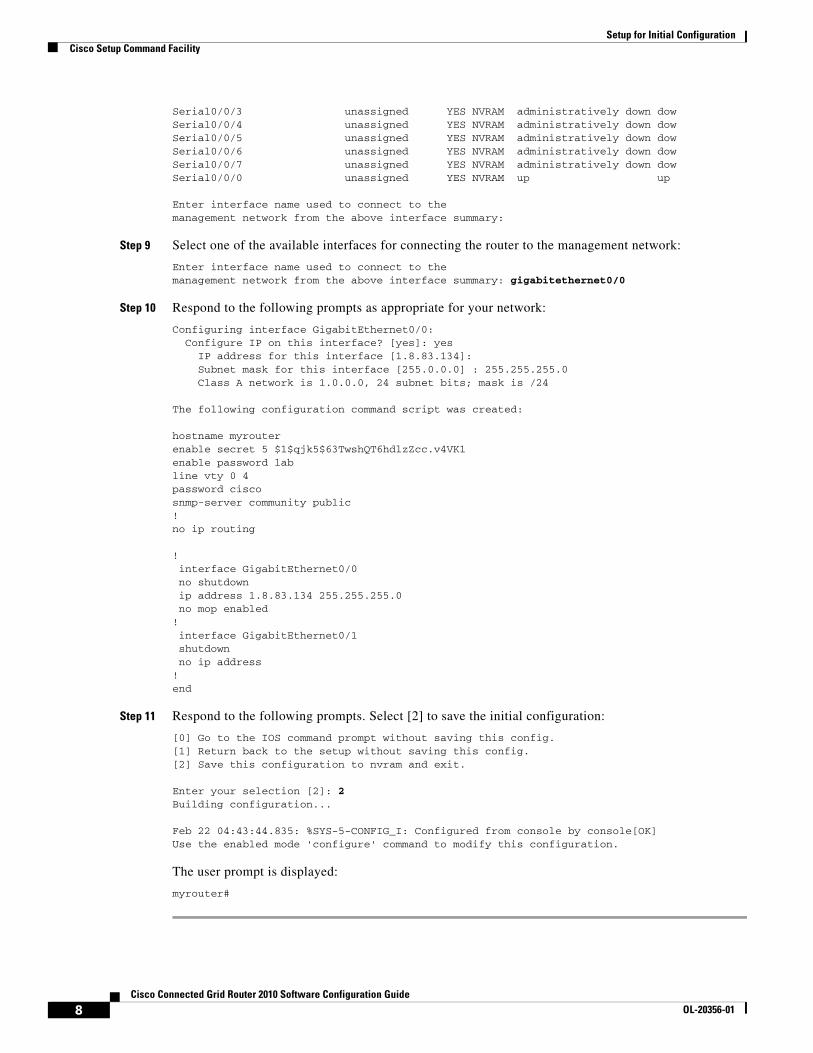
Serial0/0/3 unassigned YES NVRAM administratively down dow Serial0/0/4 unassigned YES NVRAM administratively down dow Serial0/0/5 unassigned YES NVRAM administratively down dow Serial0/0/6 unassigned YES NVRAM administratively down dow Serial0/0/7 unassigned YES NVRAM administratively down dow Serial0/0/0 unassigned YES NVRAM up up
Enter interface name used to connect to themanagement network from the above interface summary:
Step 9 Select one of the available interfaces for connecting the router to the management network:
Enter interface name used to connect to themanagement network from the above interface summary: gigabitethernet0/0
Step 10 Respond to the following prompts as appropriate for your network:
Configuring interface GigabitEthernet0/0: Configure IP on this interface? [yes]: yes IP address for this interface [1.8.83.134]: Subnet mask for this interface [255.0.0.0] : 255.255.255.0 Class A network is 1.0.0.0, 24 subnet bits; mask is /24
The following configuration command script was created:
hostname myrouterenable secret 5 $1$qjk5$63TwshQT6hdlzZcc.v4VK1enable password labline vty 0 4password ciscosnmp-server community public!no ip routing
!interface GigabitEthernet0/0no shutdownip address 1.8.83.134 255.255.255.0no mop enabled
!interface GigabitEthernet0/1shutdownno ip address
!end
Step 11 Respond to the following prompts. Select [2] to save the initial configuration:
[0] Go to the IOS command prompt without saving this config.[1] Return back to the setup without saving this config.[2] Save this configuration to nvram and exit.
Enter your selection [2]: 2Building configuration...
Feb 22 04:43:44.835: %SYS-5-CONFIG_I: Configured from console by console[OK]Use the enabled mode 'configure' command to modify this configuration.
The user prompt is displayed:
myrouter#
8Cisco Connected Grid Router 2010 Software Configuration Guide
OL-20356-01
Setup for Initial ConfigurationVerifying the Initial Configuration
Verifying the Initial Configuration To verify that the new interfaces are operating correctly, perform the following tests:
• To verify that the interfaces and line protocol are in the correct state—up or down—enter the show interfaces command.
• To display a summary status of the interfaces configured for IP, enter the show ip interface brief command.
• To verify that you configured the correct hostname and password, enter the show configuration command.
After you complete and verify the initial configuration, you can configure your Cisco router for specific functions.
Completing the ConfigurationWhen you have provided all the information requested by the setup command facility, the configuration appears. To complete your router configuration, follow these steps:
Step 1 A setup command facility prompts you to save the configuration.
• If you answer no, the configuration information you entered is not saved, and you return to the router enable prompt (Router#). Enter setup to return to the System Configuration Dialog.
• If you answer yes, the configuration is saved, and you are returned to the user EXEC prompt (Router>).
Step 2 When the messages stop appearing on your screen, press Return to get the Router> prompt.
Note If you see the next message, it means that no other AppleTalk routers were found on the network attached to the port.
%AT-6-ONLYROUTER: Ethernet0/0: AppleTalk port enabled; no neighbors found
Step 3 The Router> prompt indicates that you are now at the CLI, and you have just completed a initial router configuration. Nevertheless, this is not a complete configuration. At this point, you have two choices:
• Run the setup command facility again, and create another configuration.
Router> enablePassword: passwordRouter# setup
• Modify the existing configuration or configure additional features using the CLI:
Router> enablePassword: passwordRouter# configure terminalRouter(config)#
9Cisco Connected Grid Router 2010 Software Configuration Guide
OL-20356-01

Setup for Initial ConfigurationCompleting the Configuration
10Cisco Connected Grid Router 2010 Software Configuration Guide
OL-20356-01
Cisco IOS CLI for Initial Configuration
First Published: May 27, 2010, OL-20356-01Last Updated: October 25, 2017
This module describes how to perform the initial configuration using the Cisco Internet Operating System (IOS) command-line interface on Cisco Connected Grid Router 2010.
Note We recommend using Cisco Configuration Professional Express, a web-based GUI that lets you perform the initial configuration.
Contents• Cisco Configuration Professional Express, page 11
• Prerequisites for Initial Software Configuration Using the Cisco IOS CLI, page 12
• Using the Cisco IOS CLI to Perform Initial Configuration, page 12
Cisco Configuration Professional ExpressAfter you connect cables and supply power to the router, use Cisco Configuration Professional Express web-based application to configure the initial router settings. See Cisco Configuration Professional Express User Guide for detailed instructions.
Americas Headquarters:Cisco Systems, Inc., 170 West Tasman Drive, San Jose, CA 95134-1706 USA
© 2010-2017 Cisco Systems, Inc. All rights reserved.

Cisco IOS CLI for Initial ConfigurationPrerequisites for Initial Software Configuration Using the Cisco IOS CLI
Prerequisites for Initial Software Configuration Using the Cisco IOS CLI
Follow the instructions in the Cisco Connected Grid Router 2010 hardware installation guide to install the chassis, connect cables, and supply power to the router.
Timesaver Before supplying power to the router, disconnect all WAN cables from the router to keep it from trying to run the AutoInstall process. The router tries to run AutoInstall if you power it on while there is a WAN connection on both ends and the router does not have a valid configuration file stored in NVRAM (for instance, when you add a new interface). It can take several minutes for the router to determine that AutoInstall is not connected to a remote TCP/IP host.
Using the Cisco IOS CLI to Perform Initial ConfigurationThis section contains the following procedures:
• Configuring the Router Hostname, page 12 (Optional)
• Configuring the Enable and Enable Secret Passwords, page 13 (Required)
• Configuring the Console Idle Privileged EXEC Timeout, page 15 (Optional)
• Configuring Gigabit Ethernet Interfaces, page 16 (Required)
• Specifying a Default Route or Gateway of Last Resort, page 19 (Required)
• Configuring Virtual Terminal Lines for Remote Console Access, page 22 (Required)
• Securing Access to the Ethernet Switch Module (ESM), page 24
• Configuring the Auxiliary Line, page 26 (Optional)
• Verifying Network Connectivity, page 28 (Required)
• Saving Your Router Configuration, page 29 (Required)
• Saving Backup Copies of Configuration and System Image, page 29 (Optional)
• Monitoring Environmental Parameters, page 31
Configuring the Router HostnameThe hostname is used in CLI prompts and default configuration filenames. If you do not configure the router hostname, the router uses the factory-assigned default hostname “Router.”
Do not expect case sensitivity to be preserved in the hostname. Uppercase and lowercase characters are treated identically by many Internet software applications. Conventions dictate that computer names appear in all lowercase characters. For more information, see RFC 1178, Choosing a Name for Your Computer.
The name must also follow the rules for ARPANET hostnames. They must start with a letter, end with a letter or digit, and have only letters, digits, and hyphens as interior characters. Names must be 63 characters or fewer. For more information, see RFC 1035, Domain Names—Implementation and Specification.
12Cisco Connected Grid Router 2010 Software Configuration Guide
OL-20356-01
Cisco IOS CLI for Initial ConfigurationUsing the Cisco IOS CLI to Perform Initial Configuration
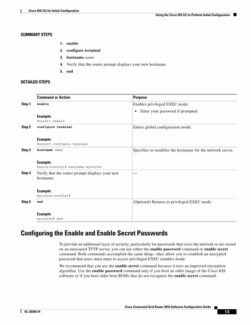
SUMMARY STEPS
1. enable
2. configure terminal
3. hostname name
4. Verify that the router prompt displays your new hostname.
5. end
DETAILED STEPS
Configuring the Enable and Enable Secret PasswordsTo provide an additional layer of security, particularly for passwords that cross the network or are stored on an unsecured TFTP server, you can use either the enable password command or enable secret command. Both commands accomplish the same thing—they allow you to establish an encrypted password that users must enter to access privileged EXEC (enable) mode.
We recommend that you use the enable secret command because it uses an improved encryption algorithm. Use the enable password command only if you boot an older image of the Cisco IOS software or if you boot older boot ROMs that do not recognize the enable secret command.
Command or Action Purpose
Step 1 enable
Example:Router> enable
Enables privileged EXEC mode.
• Enter your password if prompted.
Step 2 configure terminal
Example:Router# configure terminal
Enters global configuration mode.
Step 3 hostname name
Example:Router(config)# hostname myrouter
Specifies or modifies the hostname for the network server.
Step 4 Verify that the router prompt displays your new hostname.
Example:myrouter(config)#
—
Step 5 end
Example:myrouter# end
(Optional) Returns to privileged EXEC mode.
13Cisco Connected Grid Router 2010 Software Configuration Guide
OL-20356-01
Cisco IOS CLI for Initial ConfigurationUsing the Cisco IOS CLI to Perform Initial Configuration
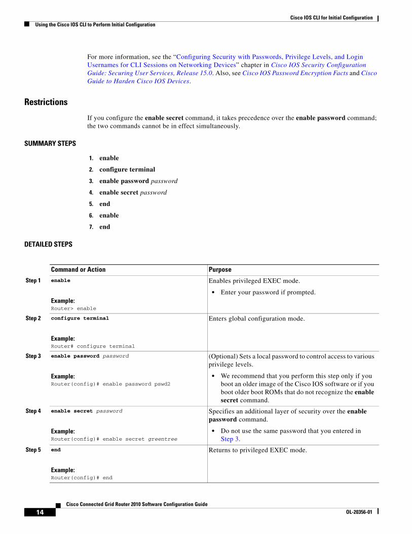
For more information, see the “Configuring Security with Passwords, Privilege Levels, and Login Usernames for CLI Sessions on Networking Devices” chapter in Cisco IOS Security Configuration Guide: Securing User Services, Release 15.0. Also, see Cisco IOS Password Encryption Facts and Cisco Guide to Harden Cisco IOS Devices.
Restrictions
If you configure the enable secret command, it takes precedence over the enable password command; the two commands cannot be in effect simultaneously.
SUMMARY STEPS
1. enable
2. configure terminal
3. enable password password
4. enable secret password
5. end
6. enable
7. end
DETAILED STEPS
Command or Action Purpose
Step 1 enable
Example:Router> enable
Enables privileged EXEC mode.
• Enter your password if prompted.
Step 2 configure terminal
Example:Router# configure terminal
Enters global configuration mode.
Step 3 enable password password
Example:Router(config)# enable password pswd2
(Optional) Sets a local password to control access to various privilege levels.
• We recommend that you perform this step only if you boot an older image of the Cisco IOS software or if you boot older boot ROMs that do not recognize the enable secret command.
Step 4 enable secret password
Example:Router(config)# enable secret greentree
Specifies an additional layer of security over the enable password command.
• Do not use the same password that you entered in Step 3.
Step 5 end
Example:Router(config)# end
Returns to privileged EXEC mode.
14Cisco Connected Grid Router 2010 Software Configuration Guide
OL-20356-01
Cisco IOS CLI for Initial ConfigurationUsing the Cisco IOS CLI to Perform Initial Configuration
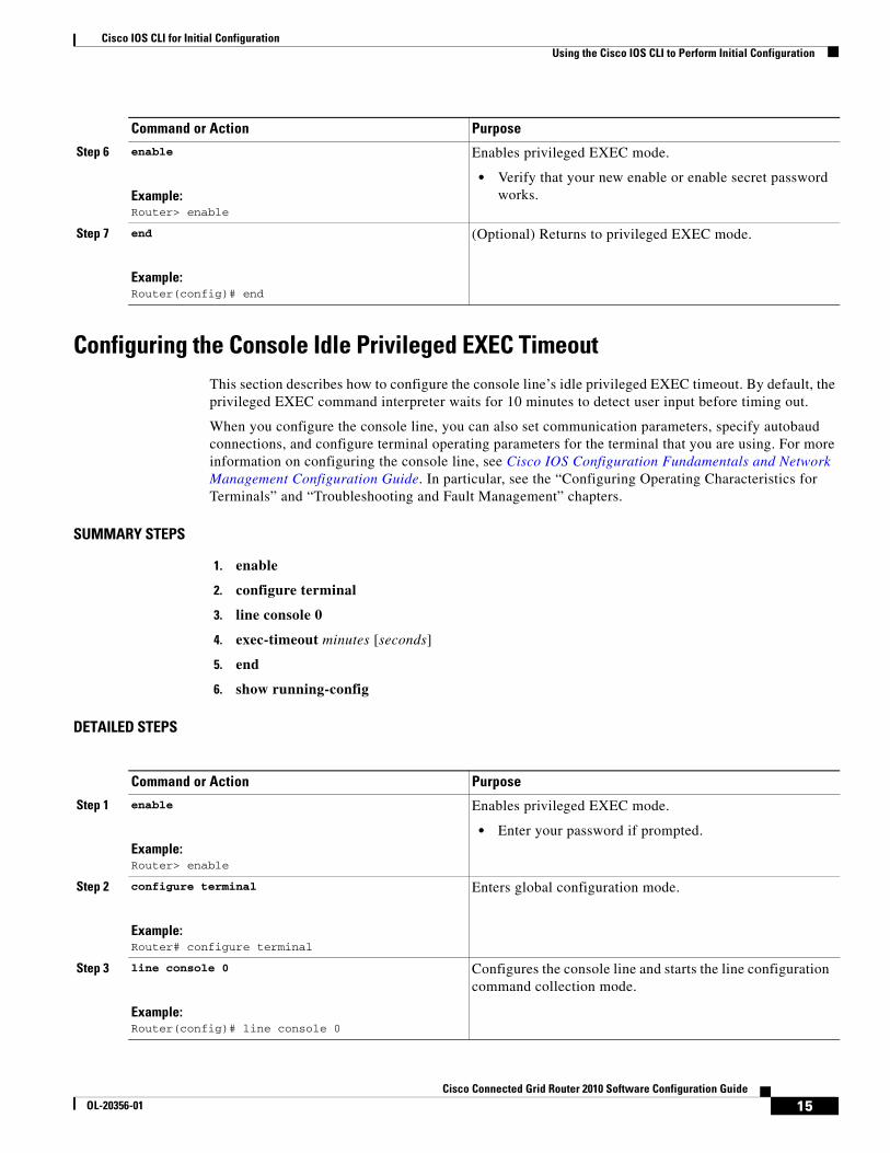
Configuring the Console Idle Privileged EXEC TimeoutThis section describes how to configure the console line’s idle privileged EXEC timeout. By default, the privileged EXEC command interpreter waits for 10 minutes to detect user input before timing out.
When you configure the console line, you can also set communication parameters, specify autobaud connections, and configure terminal operating parameters for the terminal that you are using. For more information on configuring the console line, see Cisco IOS Configuration Fundamentals and Network Management Configuration Guide. In particular, see the “Configuring Operating Characteristics for Terminals” and “Troubleshooting and Fault Management” chapters.
SUMMARY STEPS
1. enable
2. configure terminal
3. line console 0
4. exec-timeout minutes [seconds]
5. end
6. show running-config
DETAILED STEPS
Step 6 enable
Example:Router> enable
Enables privileged EXEC mode.
• Verify that your new enable or enable secret password works.
Step 7 end
Example:Router(config)# end
(Optional) Returns to privileged EXEC mode.
Command or Action Purpose
Command or Action Purpose
Step 1 enable
Example:Router> enable
Enables privileged EXEC mode.
• Enter your password if prompted.
Step 2 configure terminal
Example:Router# configure terminal
Enters global configuration mode.
Step 3 line console 0
Example:Router(config)# line console 0
Configures the console line and starts the line configuration command collection mode.
15Cisco Connected Grid Router 2010 Software Configuration Guide
OL-20356-01
Cisco IOS CLI for Initial ConfigurationUsing the Cisco IOS CLI to Perform Initial Configuration
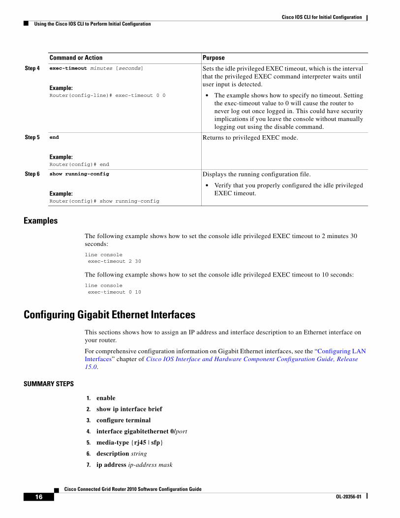
Examples
The following example shows how to set the console idle privileged EXEC timeout to 2 minutes 30 seconds:
line console exec-timeout 2 30
The following example shows how to set the console idle privileged EXEC timeout to 10 seconds:
line console exec-timeout 0 10
Configuring Gigabit Ethernet InterfacesThis sections shows how to assign an IP address and interface description to an Ethernet interface on your router.
For comprehensive configuration information on Gigabit Ethernet interfaces, see the “Configuring LAN Interfaces” chapter of Cisco IOS Interface and Hardware Component Configuration Guide, Release 15.0.
SUMMARY STEPS
1. enable
2. show ip interface brief
3. configure terminal
4. interface gigabitethernet 0/port
5. media-type {rj45 | sfp}
6. description string
7. ip address ip-address mask
Step 4 exec-timeout minutes [seconds]
Example:Router(config-line)# exec-timeout 0 0
Sets the idle privileged EXEC timeout, which is the interval that the privileged EXEC command interpreter waits until user input is detected.
• The example shows how to specify no timeout. Setting the exec-timeout value to 0 will cause the router to never log out once logged in. This could have security implications if you leave the console without manually logging out using the disable command.
Step 5 end
Example:Router(config)# end
Returns to privileged EXEC mode.
Step 6 show running-config
Example:Router(config)# show running-config
Displays the running configuration file.
• Verify that you properly configured the idle privileged EXEC timeout.
Command or Action Purpose
16Cisco Connected Grid Router 2010 Software Configuration Guide
OL-20356-01

Cisco IOS CLI for Initial ConfigurationUsing the Cisco IOS CLI to Perform Initial Configuration
8. no shutdown
9. end
10. show ip interface brief
DETAILED STEPS
Command or Action Purpose
Step 1 enable
Example:Router> enable
Enables privileged EXEC mode.
• Enter your password if prompted.
Step 2 show ip interface brief
Example:Router# show ip interface brief
Displays a brief status of the interfaces that are configured for IP.
• Learn which type of Ethernet interface is on your router.
Step 3 configure terminal
Example:Router# configure terminal
Enters global configuration mode.
Step 4 interface gigabitethernet 0/port
Example:Router(config)# interface gigabitethernet 0/0
Specifies the Gigabit Ethernet interface and enters interface configuration mode.
Step 5 media-type {rj45 | sfp}
Example:Router(config-if)# media-type sfpRouter(config-if)#
Example:Router(config-if)# media-type rj45Router(config-if)#
Designates SFP port as the primary media.
or
Designates RJ45 as the primary media.
Step 6 description string
Example:Router(config-if)# description GE int to 2nd floor south wing
(Optional) Adds a description to an interface configuration.
• The description helps you remember what is attached to this interface. The description can be useful for troubleshooting.
Step 7 ip address ip-address mask
Example:Router(config-if)# ip address 172.16.74.3 255.255.255.0
Sets a primary IP address for an interface.
Step 8 no shutdown
Example:Router(config-if)# no shutdown
Enables an interface.
17Cisco Connected Grid Router 2010 Software Configuration Guide
OL-20356-01
Cisco IOS CLI for Initial ConfigurationUsing the Cisco IOS CLI to Perform Initial Configuration
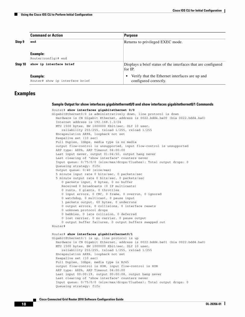
Examples
Sample Output for show interfaces gigabitethernet0/0 and show interfaces gigabitethernet0/1 CommandsRouter# show interfaces gigabitethernet 0/0GigabitEthernet0/0 is administratively down, line protocol is down Hardware is CN Gigabit Ethernet, address is 0022.bdd4.ba00 (bia 0022.bdd4.ba0) Internet address is 192.168.1.2/24 MTU 1500 bytes, BW 1000000 Kbit/sec, DLY 10 usec, reliability 255/255, txload 1/255, rxload 1/255 Encapsulation ARPA, loopback not set Keepalive set (10 sec) Full Duplex, 1Gbps, media type is no media output flow-control is unsupported, input flow-control is unsupported ARP type: ARPA, ARP Timeout 04:00:00 Last input never, output 01:04:50, output hang never Last clearing of "show interface" counters never Input queue: 0/75/0/0 (size/max/drops/flushes); Total output drops: 0 Queueing strategy: fifo Output queue: 0/40 (size/max) 5 minute input rate 0 bits/sec, 0 packets/sec 5 minute output rate 0 bits/sec, 0 packets/sec 0 packets input, 0 bytes, 0 no buffer Received 0 broadcasts (0 IP multicasts) 0 runts, 0 giants, 0 throttles 0 input errors, 0 CRC, 0 frame, 0 overrun, 0 ignored 0 watchdog, 0 multicast, 0 pause input 1 packets output, 60 bytes, 0 underruns 0 output errors, 0 collisions, 0 interface resets 0 unknown protocol drops 0 babbles, 0 late collision, 0 deferred 0 lost carrier, 0 no carrier, 0 pause output 0 output buffer failures, 0 output buffers swapped outRouter#
Router# show interfaces gigabitethernet0/1GigabitEthernet0/1 is up, line protocol is up Hardware is CN Gigabit Ethernet, address is 0022.bdd4.ba01 (bia 0022.bdd4.ba0) MTU 1500 bytes, BW 1000000 Kbit/sec, DLY 10 usec, reliability 255/255, txload 1/255, rxload 1/255 Encapsulation ARPA, loopback not set Keepalive set (10 sec) Full Duplex, 1Gbps, media type is RJ45 output flow-control is XON, input flow-control is XON ARP type: ARPA, ARP Timeout 04:00:00 Last input 00:00:19, output 00:00:08, output hang never Last clearing of "show interface" counters never Input queue: 0/75/0/0 (size/max/drops/flushes); Total output drops: 0 Queueing strategy: fifo
Step 9 end
Example:Router(config)# end
Returns to privileged EXEC mode.
Step 10 show ip interface brief
Example:Router# show ip interface brief
Displays a brief status of the interfaces that are configured for IP.
• Verify that the Ethernet interfaces are up and configured correctly.
Command or Action Purpose
18Cisco Connected Grid Router 2010 Software Configuration Guide
OL-20356-01
Cisco IOS CLI for Initial ConfigurationUsing the Cisco IOS CLI to Perform Initial Configuration
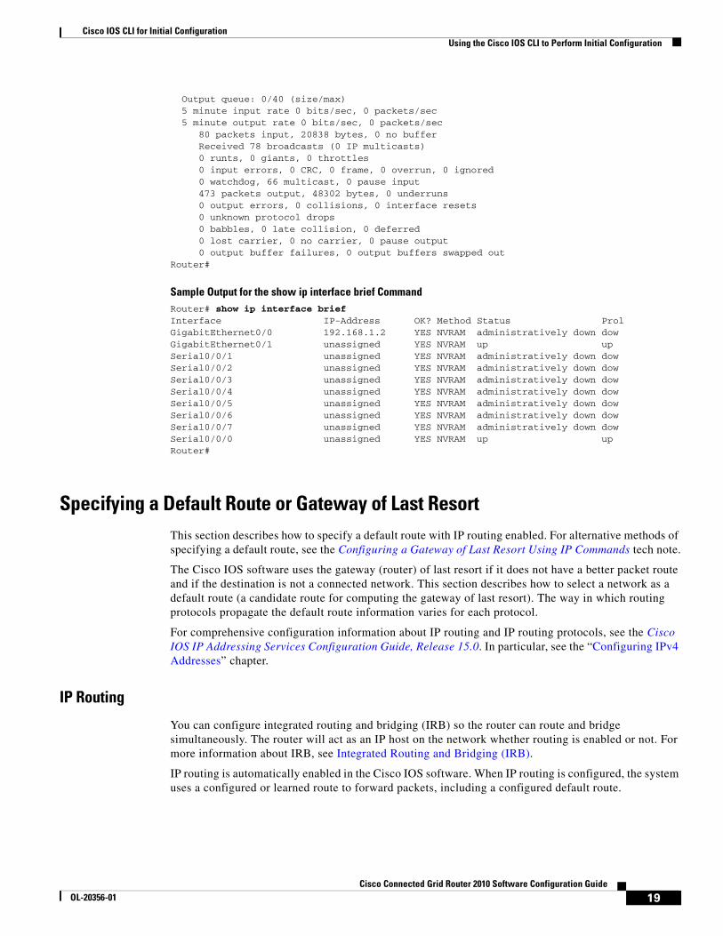
Output queue: 0/40 (size/max) 5 minute input rate 0 bits/sec, 0 packets/sec 5 minute output rate 0 bits/sec, 0 packets/sec 80 packets input, 20838 bytes, 0 no buffer Received 78 broadcasts (0 IP multicasts) 0 runts, 0 giants, 0 throttles 0 input errors, 0 CRC, 0 frame, 0 overrun, 0 ignored 0 watchdog, 66 multicast, 0 pause input 473 packets output, 48302 bytes, 0 underruns 0 output errors, 0 collisions, 0 interface resets 0 unknown protocol drops 0 babbles, 0 late collision, 0 deferred 0 lost carrier, 0 no carrier, 0 pause output 0 output buffer failures, 0 output buffers swapped outRouter#
Sample Output for the show ip interface brief CommandRouter# show ip interface brief Interface IP-Address OK? Method Status ProlGigabitEthernet0/0 192.168.1.2 YES NVRAM administratively down dow GigabitEthernet0/1 unassigned YES NVRAM up up Serial0/0/1 unassigned YES NVRAM administratively down dow Serial0/0/2 unassigned YES NVRAM administratively down dow Serial0/0/3 unassigned YES NVRAM administratively down dow Serial0/0/4 unassigned YES NVRAM administratively down dow Serial0/0/5 unassigned YES NVRAM administratively down dow Serial0/0/6 unassigned YES NVRAM administratively down dow Serial0/0/7 unassigned YES NVRAM administratively down dow Serial0/0/0 unassigned YES NVRAM up up Router#
Specifying a Default Route or Gateway of Last ResortThis section describes how to specify a default route with IP routing enabled. For alternative methods of specifying a default route, see the Configuring a Gateway of Last Resort Using IP Commands tech note.
The Cisco IOS software uses the gateway (router) of last resort if it does not have a better packet route and if the destination is not a connected network. This section describes how to select a network as a default route (a candidate route for computing the gateway of last resort). The way in which routing protocols propagate the default route information varies for each protocol.
For comprehensive configuration information about IP routing and IP routing protocols, see the Cisco IOS IP Addressing Services Configuration Guide, Release 15.0. In particular, see the “Configuring IPv4 Addresses” chapter.
IP Routing
You can configure integrated routing and bridging (IRB) so the router can route and bridge simultaneously. The router will act as an IP host on the network whether routing is enabled or not. For more information about IRB, see Integrated Routing and Bridging (IRB).
IP routing is automatically enabled in the Cisco IOS software. When IP routing is configured, the system uses a configured or learned route to forward packets, including a configured default route.
19Cisco Connected Grid Router 2010 Software Configuration Guide
OL-20356-01

Cisco IOS CLI for Initial ConfigurationUsing the Cisco IOS CLI to Perform Initial Configuration
Note This task section does not apply when IP routing is disabled. To specify a default route when IP routing is disabled, refer to Configuring a Gateway of Last Resort Using IP Commands.
Default Routes
A router might not be able to determine the routes to all other networks. To provide complete routing capability, the common practice is to use some routers as smart routers and give the remaining routers default routes to the smart router. (Smart routers have routing table information for the entire internetwork.) These default routes can be passed along dynamically, or can be configured into the individual routers.
Most dynamic interior routing protocols include a mechanism for causing a smart router to generate dynamic default information that is then passed along to other routers.
Default Network
If a router has an interface that is directly connected to the specified default network, the dynamic routing protocols running on the router will generate or source a default route. In the case of Routing Information Protocol (RIP), the router advertises the pseudonetwork 0.0.0.0. In the case of Interior Gateway Routing Protocol (IGRP), the network itself is advertised and flagged as an exterior route.
A router that is generating the default for a network also may need a default of its own. One way a router can generate its own default is to specify a static route to the network 0.0.0.0 through the appropriate device.
Gateway of Last Resort
When default information is being passed along through a dynamic routing protocol, no further configuration is required. The system periodically scans its routing table to choose the optimal default network as its default route. In the case of RIP, there is only one choice, network 0.0.0.0. In the case of IGRP, there might be several networks that can be candidates for the system default. The Cisco IOS software uses both administrative distance and metric information to determine the default route (gateway of last resort). The selected default route appears in the gateway of last resort display of the show ip route EXEC command.
If dynamic default information is not being passed to the software, candidates for the default route are specified with the ip default-network global configuration command. In this usage, the ip default-network command takes an unconnected network as an argument. If this network appears in the routing table from any source (dynamic or static), it is flagged as a candidate default route and is a possible choice as the default route.
If the router has no interface on the default network, but does have a route to it, it considers this network as a candidate default path. The route candidates are examined and the best one is chosen, based on administrative distance and metric. The gateway to the best default path becomes the gateway of last resort.
SUMMARY STEPS
1. enable
2. configure terminal
3. ip routing
20Cisco Connected Grid Router 2010 Software Configuration Guide
OL-20356-01
Cisco IOS CLI for Initial ConfigurationUsing the Cisco IOS CLI to Perform Initial Configuration
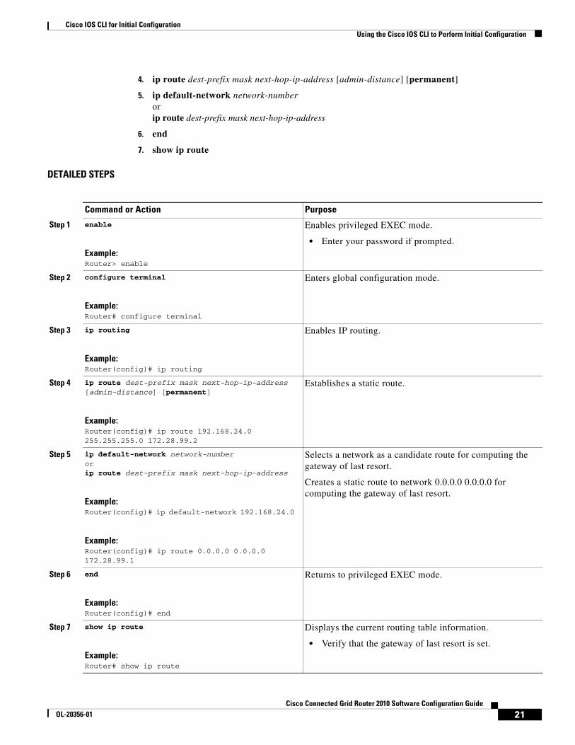
4. ip route dest-prefix mask next-hop-ip-address [admin-distance] [permanent]
5. ip default-network network-number orip route dest-prefix mask next-hop-ip-address
6. end
7. show ip route
DETAILED STEPS
Command or Action Purpose
Step 1 enable
Example:Router> enable
Enables privileged EXEC mode.
• Enter your password if prompted.
Step 2 configure terminal
Example:Router# configure terminal
Enters global configuration mode.
Step 3 ip routing
Example:Router(config)# ip routing
Enables IP routing.
Step 4 ip route dest-prefix mask next-hop-ip-address [admin-distance] [permanent]
Example:Router(config)# ip route 192.168.24.0 255.255.255.0 172.28.99.2
Establishes a static route.
Step 5 ip default-network network-number orip route dest-prefix mask next-hop-ip-address
Example:Router(config)# ip default-network 192.168.24.0
Example:Router(config)# ip route 0.0.0.0 0.0.0.0 172.28.99.1
Selects a network as a candidate route for computing the gateway of last resort.
Creates a static route to network 0.0.0.0 0.0.0.0 for computing the gateway of last resort.
Step 6 end
Example:Router(config)# end
Returns to privileged EXEC mode.
Step 7 show ip route
Example:Router# show ip route
Displays the current routing table information.
• Verify that the gateway of last resort is set.
21Cisco Connected Grid Router 2010 Software Configuration Guide
OL-20356-01
Cisco IOS CLI for Initial ConfigurationUsing the Cisco IOS CLI to Perform Initial Configuration
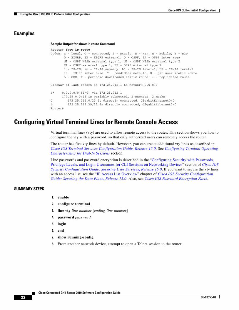
Examples
Sample Output for show ip route CommandRouter# show ip route Codes: L - local, C - connected, S - static, R - RIP, M - mobile, B - BGP D - EIGRP, EX - EIGRP external, O - OSPF, IA - OSPF inter area N1 - OSPF NSSA external type 1, N2 - OSPF NSSA external type 2 E1 - OSPF external type 1, E2 - OSPF external type 2 i - IS-IS, su - IS-IS summary, L1 - IS-IS level-1, L2 - IS-IS level-2 ia - IS-IS inter area, * - candidate default, U - per-user static route o - ODR, P - periodic downloaded static route, + - replicated route
Gateway of last resort is 172.25.212.1 to network 0.0.0.0
S* 0.0.0.0/0 [1/0] via 172.25.212.1 172.25.0.0/16 is variably subnetted, 2 subnets, 2 masksC 172.25.212.0/25 is directly connected, GigabitEthernet0/0L 172.25.212.39/32 is directly connected, GigabitEthernet0/0Router#
Configuring Virtual Terminal Lines for Remote Console AccessVirtual terminal lines (vty) are used to allow remote access to the router. This section shows you how to configure the vty with a password, so that only authorized users can remotely access the router.
The router has five vty lines by default. However, you can create additional vty lines as described in Cisco IOS Terminal Services Configuration Guide, Release 15.0. See Configuring Terminal Operating Characteristics for Dial-In Sessions section.
Line passwords and password encryption is described in the “Configuring Security with Passwords, Privilege Levels, and Login Usernames for CLI Sessions on Networking Devices” section of Cisco IOS Security Configuration Guide: Securing User Services, Release 15.0. If you want to secure the vty lines with an access list, see the “IP Access List Overview” chapter of Cisco IOS Security Configuration Guide: Securing the Data Plane, Release 15.0. Also, see Cisco IOS Password Encryption Facts.
SUMMARY STEPS
1. enable
2. configure terminal
3. line vty line-number [ending-line-number]
4. password password
5. login
6. end
7. show running-config
8. From another network device, attempt to open a Telnet session to the router.
22Cisco Connected Grid Router 2010 Software Configuration Guide
OL-20356-01

Cisco IOS CLI for Initial ConfigurationUsing the Cisco IOS CLI to Perform Initial Configuration
DETAILED STEPS
Examples
The following example shows how to configure virtual terminal lines with a password:
!line vty 0 4
Command or Action Purpose
Step 1 enable
Example:Router> enable
Enables privileged EXEC mode.
• Enter your password if prompted.
Step 2 configure terminal
Example:Router# configure terminal
Enters global configuration mode.
Step 3 line vty line-number [ending-line-number]
Example:Router(config)# line vty 0 4
Starts the line configuration command collection mode for the vty for remote console access.
• Make sure that you configure all vty lines on your router.
Note To verify the number of vty lines on your router, use the line vty ? command.
Step 4 password password
Example:Router(config-line)# password guessagain
Specifies a password on a line.
Step 5 login
Example:Router(config-line)# login
Enables password checking at login.
Step 6 end
Example:Router(config-line)# end
Returns to privileged EXEC mode.
Step 7 show running-config
Example:Router# show running-config
Displays the running configuration file.
• Verify that you properly configured the virtual terminal lines for remote access.
Step 8 From another network device, attempt to open a Telnet session to the router.
Example:Router# 172.16.74.3 Password:
Verifies that you can remotely access the router and that the virtual terminal line password is correctly configured.
23Cisco Connected Grid Router 2010 Software Configuration Guide
OL-20356-01
Cisco IOS CLI for Initial ConfigurationUsing the Cisco IOS CLI to Perform Initial Configuration
password guessagain login
!
What to Do Next
After you configure the vty lines, complete these steps:
• (Optional) To encrypt the virtual terminal line password, see the “Configuring Security with Passwords, Privilege Levels, and Login Usernames for CLI Sessions on Networking Devices” section of Cisco IOS Security Configuration Guide: Securing User Services, Release 15.0. Also, see Cisco IOS Password Encryption Facts.
• (Optional) To secure the vty lines with an access list, see Cisco IOS Security Configuration Guide: Securing the Data Plane, Release 15.0.
• (Optional) To configure an ACL on the line for the Ethernet Switch Module (ESM) to secure access to the CGR 2010 and ESM, see Securing Access to the Ethernet Switch Module (ESM), page 24.
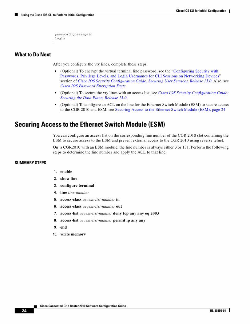
Securing Access to the Ethernet Switch Module (ESM)You can configure an access list on the corresponding line number of the CGR 2010 slot containing the ESM to secure access to the ESM and prevent external access to the CGR 2010 using reverse telnet.
On a CGR2010 with an ESM module, the line number is always either 3 or 131. Perform the following steps to determine the line number and apply the ACL to that line.
SUMMARY STEPS
1. enable
2. show line
3. configure terminal
4. line line-number
5. access-class access-list-number in
6. access-class access-list-number out
7. access-list access-list-number deny tcp any any eq 2003
8. access-list access-list-number permit ip any any
9. end
10. write memory
24Cisco Connected Grid Router 2010 Software Configuration Guide
OL-20356-01
Cisco IOS CLI for Initial ConfigurationUsing the Cisco IOS CLI to Perform Initial Configuration
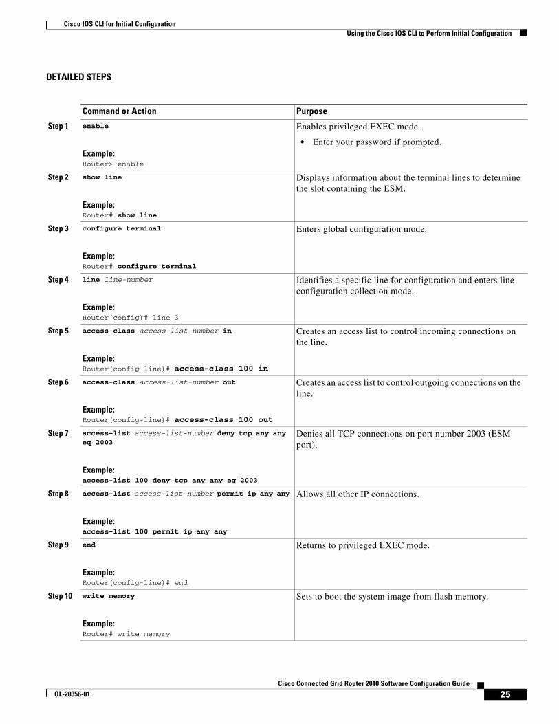
DETAILED STEPS
Command or Action Purpose
Step 1 enable
Example:Router> enable
Enables privileged EXEC mode.
• Enter your password if prompted.
Step 2 show line
Example:Router# show line
Displays information about the terminal lines to determine the slot containing the ESM.
Step 3 configure terminal
Example:Router# configure terminal
Enters global configuration mode.
Step 4 line line-number
Example:Router(config)# line 3
Identifies a specific line for configuration and enters line configuration collection mode.
Step 5 access-class access-list-number in
Example:Router(config-line)# access-class 100 in
Creates an access list to control incoming connections on the line.
Step 6 access-class access-list-number out
Example:Router(config-line)# access-class 100 out
Creates an access list to control outgoing connections on the line.
Step 7 access-list access-list-number deny tcp any any eq 2003
Example:access-list 100 deny tcp any any eq 2003
Denies all TCP connections on port number 2003 (ESM port).
Step 8 access-list access-list-number permit ip any any
Example:access-list 100 permit ip any any
Allows all other IP connections.
Step 9 end
Example:Router(config-line)# end
Returns to privileged EXEC mode.
Step 10 write memory
Example:Router# write memory
Sets to boot the system image from flash memory.
25Cisco Connected Grid Router 2010 Software Configuration Guide
OL-20356-01
Cisco IOS CLI for Initial ConfigurationUsing the Cisco IOS CLI to Perform Initial Configuration
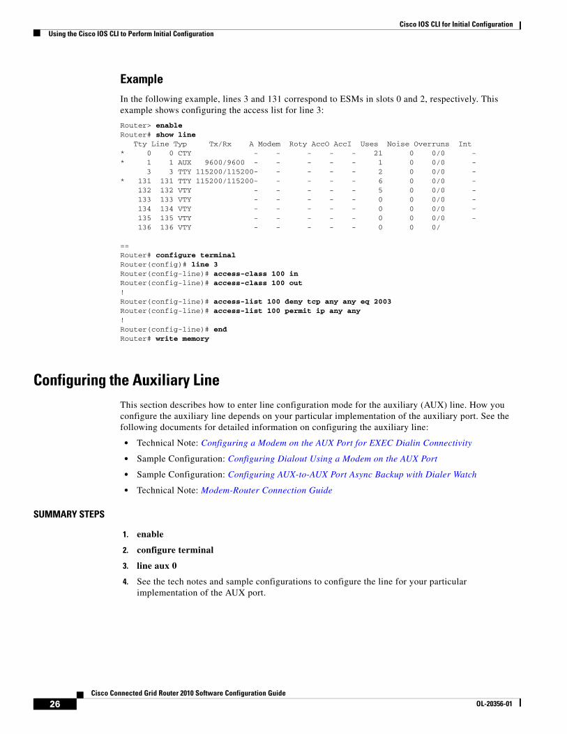
ExampleIn the following example, lines 3 and 131 correspond to ESMs in slots 0 and 2, respectively. This example shows configuring the access list for line 3:
Router> enableRouter# show line
Tty Line Typ Tx/Rx A Modem Roty AccO AccI Uses Noise Overruns Int* 0 0 CTY - - - - - 21 0 0/0 -* 1 1 AUX 9600/9600 - - - - - 1 0 0/0 -
3 3 TTY 115200/115200- - - - - 2 0 0/0 -* 131 131 TTY 115200/115200- - - - - 6 0 0/0 -
132 132 VTY - - - - - 5 0 0/0 - 133 133 VTY - - - - - 0 0 0/0 - 134 134 VTY - - - - - 0 0 0/0 - 135 135 VTY - - - - - 0 0 0/0 - 136 136 VTY - - - - - 0 0 0/
==Router# configure terminalRouter(config)# line 3Router(config-line)# access-class 100 inRouter(config-line)# access-class 100 out!Router(config-line)# access-list 100 deny tcp any any eq 2003Router(config-line)# access-list 100 permit ip any any!Router(config-line)# endRouter# write memory
Configuring the Auxiliary LineThis section describes how to enter line configuration mode for the auxiliary (AUX) line. How you configure the auxiliary line depends on your particular implementation of the auxiliary port. See the following documents for detailed information on configuring the auxiliary line:
• Technical Note: Configuring a Modem on the AUX Port for EXEC Dialin Connectivity
• Sample Configuration: Configuring Dialout Using a Modem on the AUX Port
• Sample Configuration: Configuring AUX-to-AUX Port Async Backup with Dialer Watch
• Technical Note: Modem-Router Connection Guide
SUMMARY STEPS
1. enable
2. configure terminal
3. line aux 0
4. See the tech notes and sample configurations to configure the line for your particular implementation of the AUX port.
26Cisco Connected Grid Router 2010 Software Configuration Guide
OL-20356-01

Cisco IOS CLI for Initial ConfigurationUsing the Cisco IOS CLI to Perform Initial Configuration
DETAILED STEPS
Command or Action Purpose
Step 1 enable
Example:Router> enable
Enables privileged EXEC mode.
• Enter your password if prompted.
Step 2 configure terminal
Example:Router# configure terminal
Enters global configuration mode.
Step 3 line aux 0
Example:Router(config)# line aux 0
Starts the line configuration command collection mode for the auxiliary line.
Step 4 See the tech notes and sample configurations to configure the line for your particular implementation of the AUX port.
—
27Cisco Connected Grid Router 2010 Software Configuration Guide
OL-20356-01

Cisco IOS CLI for Initial ConfigurationUsing the Cisco IOS CLI to Perform Initial Configuration
Verifying Network ConnectivityThis section describes how to verify network connectivity for your router.
Prerequisites
• Complete all previous configuration tasks in this document.
• The router must be connected to a properly configured network host.
SUMMARY STEPS
1. enable
2. ping [ip-address | hostname]
3. telnet {ip-address | hostname}
DETAILED STEPS
Examples
The following display shows an example output for the ping command when you ping the IP address 172.25.212.39:
Router# pingProtocol [ip]: Target IP address: 172.25.212.39Repeat count [5]: Datagram size [100]: Timeout in seconds [2]: Extended commands [n]: Sweep range of sizes [n]: Type escape sequence to abort.Sending 5, 100-byte ICMP Echos to 172.25.212.39, timeout is 2 seconds:!!!!!Success rate is 100 percent (5/5), round-trip min/avg/max = 1/1/1 msRouter#
Command or Action Purpose
Step 1 enable
Example:Router> enable
Enables privileged EXEC mode.
• Enter your password if prompted.
Step 2 ping [ip-address | hostname]
Example:Router# ping 172.16.74.5
Diagnoses initial network connectivity.
• To verify connectivity, ping the next hop router or connected host for each configured interface to.
Step 3 telnet {ip-address | hostname}
Example:Router# telnet 172.16.72.3
Logs in to a host that supports Telnet.
• If you want to test the vty line password, perform this step from a different network device, and use your router’s IP address.
28Cisco Connected Grid Router 2010 Software Configuration Guide
OL-20356-01

Cisco IOS CLI for Initial ConfigurationUsing the Cisco IOS CLI to Perform Initial Configuration
The following display shows an example output for the ping command when you ping the IP hostname donald:
Router# ping donald
Type escape sequence to abort.Sending 5, 100-byte ICMP Echos to 172.168.7.27, timeout is 2 seconds:!!!!!Success rate is 100 percent, round-trip min/avg/max = 1/3/4 ms
Saving Your Router ConfigurationThis section describes how to avoid losing your configuration at the next system reload or power cycle by saving the running configuration to the startup configuration in NVRAM. The NVRAM provides 256KB of storage on the router.
SUMMARY STEPS
1. enable
2. copy running-config startup-config
DETAILED STEPS
Saving Backup Copies of Configuration and System ImageTo aid file recovery and minimize downtime in case of file corruption, we recommend that you save backup copies of the startup configuration file and the Cisco IOS software system image file on a server.
SUMMARY STEPS
1. enable
2. copy nvram:startup-config {ftp: | rcp: | tftp:}
3. show {flash0 | flash1}:
4. copy {flash0 | flash1}: {ftp: | rcp: | tftp:}
Command or Action Purpose
Step 1 enable
Example:Router> enable
Enables privileged EXEC mode.
• Enter your password if prompted.
Step 2 copy running-config startup-config
Example:Router# copy running-config startup-config
Saves the running configuration to the startup configuration.
29Cisco Connected Grid Router 2010 Software Configuration Guide
OL-20356-01
Cisco IOS CLI for Initial ConfigurationUsing the Cisco IOS CLI to Perform Initial Configuration
DETAILED STEPS
Examples
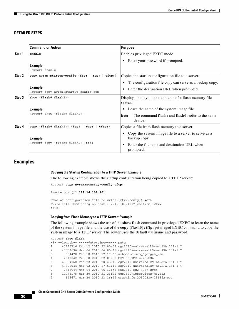
Copying the Startup Configuration to a TFTP Server: Example
The following example shows the startup configuration being copied to a TFTP server:
Router# copy nvram:startup-config tftp:
Remote host[]? 172.16.101.101
Name of configuration file to write [rtr2-confg]? <cr> Write file rtr2-confg on host 172.16.101.101?[confirm] <cr> ![OK]
Copying from Flash Memory to a TFTP Server: Example
The following example shows the use of the show flash command in privileged EXEC to learn the name of the system image file and the use of the copy {flash0}: tftp: privileged EXEC command to copy the system image to a TFTP server. The router uses the default username and password.
Router# show flash -#- --length-- -----date/time------ path1 47295716 Feb 12 2010 22:00:58 cgr2010-universalk9-mz.SPA.151-1.T2 47304696 Mar 04 2010 06:00:48 cgr2010-universalk9-mz.SPA.151-1.T3 384478 Feb 18 2010 12:17:36 u-boot-cisco_3gorges_ram4 2812042 Feb 18 2010 22:03:50 C2935R_RM2.srec.SSA5 47304060 Feb 22 2010 20:45:16 cgr2010-universalk9-mz.SPA.151-1.T6 47300944 Mar 02 2010 17:51:16 cgr2010-universalk9-mz.SPA.151-1.T7 2812044 Mar 04 2010 06:12:54 CGR2010_RM2_0227.srec8 11776175 Mar 30 2010 21:23:24 cgs2520-ipservices-mz.s129 146671 Mar 30 2010 23:16:42 crashinfo_20100330-231642-UTC
Command or Action Purpose
Step 1 enable
Example:Router> enable
Enables privileged EXEC mode.
• Enter your password if prompted.
Step 2 copy nvram:startup-config {ftp: | rcp: | tftp:}
Example:Router# copy nvram:startup-config ftp:
Copies the startup configuration file to a server.
• The configuration file copy can serve as a backup copy.
• Enter the destination URL when prompted.
Step 3 show {flash0|flash1}:
Example:Router# show {flash0|flash1}:
Displays the layout and contents of a flash memory file system.
• Learn the name of the system image file.
Note The command flash: and flash0: refer to the same device.
Step 4 copy {flash0|flash1}: {ftp: | rcp: | tftp:}
Example:Router# copy {flash0|flash1}: ftp:
Copies a file from flash memory to a server.
• Copy the system image file to a server to serve as a backup copy.
• Enter the filename and destination URL when prompted.
30Cisco Connected Grid Router 2010 Software Configuration Guide
OL-20356-01
Cisco IOS CLI for Initial ConfigurationUsing the Cisco IOS CLI to Perform Initial Configuration
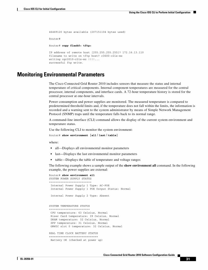
46469120 bytes available (207151104 bytes used)
Router#
Router# copy flash0: tftp:
IP address of remote host [255.255.255.255]? 172.16.13.110 filename to write on tftp host? c3600-c2is-mz writing cgr2010-c2is-mz !!!!...successful ftp write.
Monitoring Environmental ParametersThe Cisco Connected Grid Router 2010 includes sensors that measure the status and internal temperature of critical components. Internal component temperatures are measured for the central processor, internal components, and interface cards. A 72-hour temperature history is stored for the central processor at one-hour intervals.
Power consumption and power supplies are monitored. The measured temperature is compared to predetermined threshold limits and, if the temperature does not fall within the limits, the information is recorded and a warning sent to the system administrator by means of Simple Network Management Protocol (SNMP) traps until the temperature falls back to its normal range.
A command-line interface (CLI) command allows the display of the current system environment and temperature status.
Use the following CLI to monitor the system environment:
Router# show environment {all | last | table}
where:
• all—Displays all environmental monitor parameters
• last—Displays the last environmental monitor parameters
• table—Displays the table of temperature and voltage ranges
The following example shows a sample output of the show environment all command. In the following example, the power supplies are external:
Router# show environment allSYSTEM POWER SUPPLY STATUS========================== Internal Power Supply 1 Type: AC-POEInternal Power Supply 1 POE Output Status: Normal
Internal Power Supply 2 Type: Absent
SYSTEM TEMPERATURE STATUS========================= CPU temperature: 63 Celsius, Normal Riser Card temperature: 39 Celsius, Normal DRAM temperature: 32 Celsius, Normal SFP temperature: 31 Celsius, Normal GRWIC slot 0 temperature: 32 Celsius, Normal
REAL TIME CLOCK BATTERY STATUS============================== Battery OK (checked at power up)
31Cisco Connected Grid Router 2010 Software Configuration Guide
OL-20356-01

Cisco IOS CLI for Initial ConfigurationUsing the Cisco IOS CLI to Perform Initial Configuration
SYSTEM WATTAGE=============== Motherboard Components Power consumption = 19.024 W Total System Power consumption is: 19.024 W Environmental information last updated 00:00:21
Router#
The following example shows a sample output of the show environment last command. In the following example, the power supplies are external:
Router# show environment last SYSTEM POWER SUPPLY STATUS==========================Internal Power Supply 1 Type: AC-POEInternal Power Supply 1 POE Output Status: Normal
Internal Power Supply 2 Type: Absent
SYSTEM TEMPERATURE STATUS========================= CPU temperature: 63 Celsius, Normal Riser Card temperature: 38 Celsius, Normal DRAM temperature: 32 Celsius, Normal SFP temperature: 31 Celsius, Normal GRWIC slot 0 temperature: 33 Celsius, Normal
REAL TIME CLOCK BATTERY STATUS============================== Battery OK (checked at power up)Router#
The following example shows a sample output of the show environment table command. In the following example, the power supplies are external:
Router# show environment tableSYSTEM POWER SUPPLY STATUS==========================Internal Power Supply 1 Type: AC-POEInternal Power Supply 1 POE Output Status: Normal
Internal Power Supply 2 Type: Absent
SYSTEM TEMPERATURE STATUS========================= CPU temperature: 63 Celsius, Normal Riser Card temperature: 39 Celsius, Normal DRAM temperature: 32 Celsius, Normal SFP temperature: 31 Celsius, Normal GRWIC slot 0 temperature: 33 Celsius, Normal
REAL TIME CLOCK BATTERY STATUS============================== Battery OK (checked at power up)
SYSTEM ALARMS SETTINGS====================== CPU Over Temperature Alarm = 100C Riser Card Over Temperature Alarm = 100C DRAM Over Temperature Alarm = 85C SFP Over Temperature Alarm = 85C
32Cisco Connected Grid Router 2010 Software Configuration Guide
OL-20356-01

Cisco IOS CLI for Initial ConfigurationUsing the Cisco IOS CLI to Perform Initial Configuration
GRWIC slot 0 Over Temperature Alarm = 90C GRWIC slot 1 Over Temperature Alarm = 90C GRWIC slot 2 Over Temperature Alarm = 90C GRWIC slot 3 Over Temperature Alarm = 90C Power Supply Unit 1 Over Temperature Alarm = 100C Power Supply Unit 2 Over Temperature Alarm = 100C
SYSTEM VOLTAGES=============== 12V voltage = 11.944 V, Normal 5V voltage = 5.028 V, Normal 3.3V voltage = 3.288 V, Normal 2.5V voltage = 2.512 V, Normal 1.8V voltage = 1.801 V, Normal 1.2V voltage = 1.202 V, Normal ASIC voltage = 1.052 V, Normal CPU Core voltage = 1.065 V, Normal
SYSTEM WATTAGE=============== Motherboard Components Power consumption = 19.245 W Total System Power consumption is: 19.245 W
Environmental information last updated 00:00:02
ENVIRONMENTAL STRESS EVENTS===========================Critical Temperature: Maxium = 0 Total Duration = 0
------ CPU TEMPERATURE SENSOR REGISTERS ------ REG: 0x0 : 0x28REG: 0x1 : 0x3FREG: 0x2 : 0x0REG: 0x3 : 0x0REG: 0x4 : 0x4REG: 0x5 : 0x73REG: 0x6 : 0xE7REG: 0x7 : 0x78REG: 0x8 : 0xE7
------- POWER SEQUENCER REGS -------REG: 0x0 : 0x305REG: 0x1 : 0x51REG: 0x2 : 0x1REG: 0x3 : 0x1REG: 0x4 : 0x0REG: 0x5 : 0x0REG: 0x6 : 0x64BDREG: 0x7 : 0xE713REG: 0x8 : 0x2F3REG: 0x9 : 0x2F8REG: 0xA : 0x237REG: 0xB : 0x2DAREG: 0xC : 0x2DDREG: 0xD : 0x2D8REG: 0xE : 0x302REG: 0xF : 0x304REG: 0x10 : 0x300REG: 0x11 : 0x319REG: 0x12 : 0x31EREG: 0x13 : 0x317REG: 0x14 : 0x2AAREG: 0x15 : 0x2AE
33Cisco Connected Grid Router 2010 Software Configuration Guide
OL-20356-01

Cisco IOS CLI for Initial ConfigurationUsing the Cisco IOS CLI to Perform Initial Configuration
REG: 0x16 : 0x2A6REG: 0x17 : 0x57REG: 0x18 : 0x6CREG: 0x19 : 0x40REG: 0x1A : 0x1C8REG: 0x1B : 0x1CDREG: 0x1C : 0x1C4REG: 0x1D : 0x18EREG: 0x1E : 0x196REG: 0x1F : 0x18CREG: 0x20 : 0x18FREG: 0x21 : 0x199REG: 0x22 : 0x187REG: 0x23 : 0x0REG: 0x24 : 0x0REG: 0x25 : 0x0REG: 0x26 : 0x0REG: 0x27 : 0x0REG: 0x28 : 0x0REG: 0x29 : 0x0REG: 0x2A : 0x0REG: 0x2B : 0x0REG: 0x2C : 0x0REG: 0x2D : 0x0REG: 0x2E : 0x78REG: 0x2F : 0x0REG: 0x30 : 0x0REG: 0x31 : 0x4600REG: 0x32 : 0x902REG: 0x33 : 0x905REG: 0x34 : 0x905REG: 0x35 : 0x900REG: 0x36 : 0xC04REG: 0x37 : 0x903REG: 0x38 : 0x38REG: 0x39 : 0xE03REG: 0x3A : 0x8FREG: 0x3B : 0x32REG: 0x3C : 0x38REG: 0x3D : 0xFFFFREG: 0x3E : 0x0REG: 0x3F : 0x0REG: 0x40 : 0x0REG: 0x41 : 0x0REG: 0x42 : 0x0REG: 0x43 : 0x0Router#
34Cisco Connected Grid Router 2010 Software Configuration Guide
OL-20356-01
Basic Router Configuration
First Published: May 27, 2010, OL-20356-01Last Updated: October 25, 2017
This document provides basic configuration procedures for the Cisco Connected Grid Router 2010. It also includes configuration examples and verification steps, when possible.
Basic Configuration
• Default Configuration, page 34
• Configuring Basic Parameters, page 35
Interface Configuration
• Interface Ports, page 36
• Configuring Gigabit Ethernet Interfaces, page 36
• Configuring a Loopback Interface, page 37
Routing Configuration
• Configuring Command-Line Access, page 39
• Configuring Static Routes, page 40
• Configuring Dynamic Routes, page 42
• Typical Example of a Cisco CGR 2010 Configuration, page 44
Americas Headquarters:Cisco Systems, Inc., 170 West Tasman Drive, San Jose, CA 95134-1706 USA
© 2010 Cisco Systems, Inc. All rights reserved.
Basic Router ConfigurationDefault Configuration
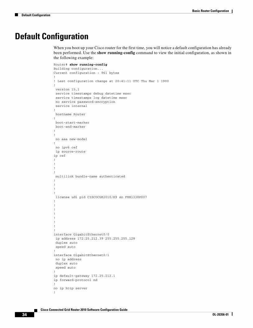
Default ConfigurationWhen you boot up your Cisco router for the first time, you will notice a default configuration has already been performed. Use the show running-config command to view the initial configuration, as shown in the following example:
Router# show running-configBuilding configuration...Current configuration : 961 bytes!! Last configuration change at 20:41:11 UTC Thu Mar 1 1900!version 15.1service timestamps debug datetime msecservice timestamps log datetime msecno service password-encryptionservice internal
!hostname Router
!boot-start-markerboot-end-marker
!!no aaa new-model
!no ipv6 cefip source-route
ip cef!!!!multilink bundle-name authenticated
!!!!license udi pid CISCOCGR2010/K9 sn FHH1338P007
!!!!!!!!interface GigabitEthernet0/0ip address 172.25.212.39 255.255.255.128duplex autospeed auto
!interface GigabitEthernet0/1no ip addressduplex autospeed auto
!ip default-gateway 172.25.212.1ip forward-protocol nd!no ip http server!
34Cisco Connected Grid Router 2010 Software Configuration Guide
OL-20356-01
Basic Router ConfigurationConfiguring Basic Parameters
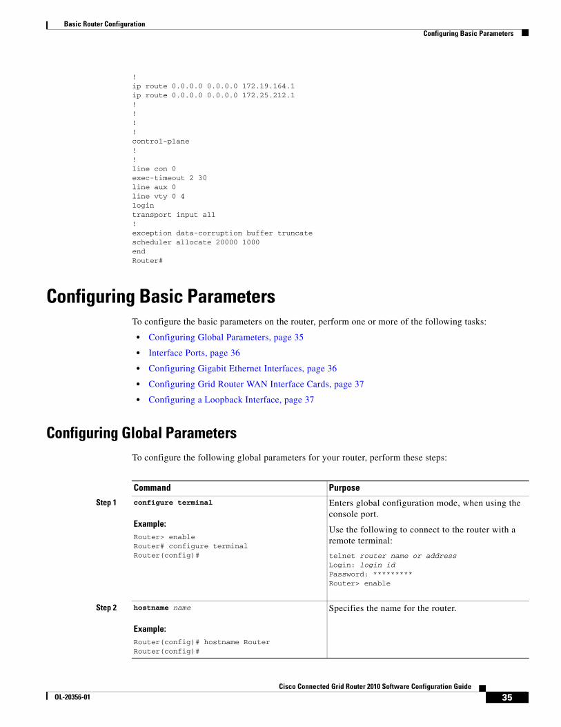
!ip route 0.0.0.0 0.0.0.0 172.19.164.1ip route 0.0.0.0 0.0.0.0 172.25.212.1!!!!control-plane!!line con 0exec-timeout 2 30line aux 0line vty 0 4logintransport input all!exception data-corruption buffer truncatescheduler allocate 20000 1000endRouter#
Configuring Basic ParametersTo configure the basic parameters on the router, perform one or more of the following tasks:
• Configuring Global Parameters, page 35
• Interface Ports, page 36
• Configuring Gigabit Ethernet Interfaces, page 36
• Configuring Grid Router WAN Interface Cards, page 37
• Configuring a Loopback Interface, page 37
Configuring Global ParametersTo configure the following global parameters for your router, perform these steps:
Command Purpose
Step 1 configure terminal
Example:Router> enableRouter# configure terminalRouter(config)#
Enters global configuration mode, when using the console port.
Use the following to connect to the router with a remote terminal:
telnet router name or addressLogin: login idPassword: *********Router> enable
Step 2 hostname name
Example:Router(config)# hostname RouterRouter(config)#
Specifies the name for the router.
35Cisco Connected Grid Router 2010 Software Configuration Guide
OL-20356-01
Basic Router ConfigurationInterface Ports
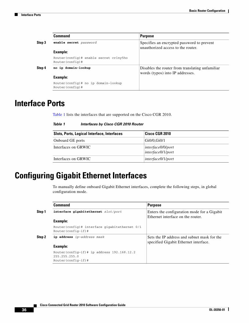
Interface PortsTable 1 lists the interfaces that are supported on the Cisco CGR 2010.
Configuring Gigabit Ethernet InterfacesTo manually define onboard Gigabit Ethernet interfaces, complete the following steps, in global configuration mode.
Step 3 enable secret password
Example:Router(config)# enable secret cr1ny5hoRouter(config)#
Specifies an encrypted password to prevent unauthorized access to the router.
Step 4 no ip domain-lookup
Example:Router(config)# no ip domain-lookup Router(config)#
Disables the router from translating unfamiliar words (typos) into IP addresses.
Command Purpose
Table 1 Interfaces by Cisco CGR 2010 Router
Slots, Ports, Logical Interface, Interfaces Cisco CGR 2010
Onboard GE ports Gi0/0,Gi0/1
Interfaces on GRWIC interface0/0/portinterface0/1/port
Interfaces on GRWIC interface0/1/port
Command Purpose
Step 1 interface gigabitethernet slot/port
Example:Router(config)# interface gigabitethernet 0/1Router(config-if)#
Enters the configuration mode for a Gigabit Ethernet interface on the router.
Step 2 ip address ip-address mask
Example:Router(config-if)# ip address 192.168.12.2 255.255.255.0Router(config-if)#
Sets the IP address and subnet mask for the specified Gigabit Ethernet interface.
36Cisco Connected Grid Router 2010 Software Configuration Guide
OL-20356-01

Basic Router ConfigurationConfiguring Grid Router WAN Interface Cards
Configuring Grid Router WAN Interface CardsThe Cisco Connected Grid Router 2010 supports RS-232 low-speed serial Grid Router WAN Interface Cards (GRWICs) and T1/E1 channelized and clear channel GRWICs.
Configuring the 8-Port RS-232 Serial GRWICsTo configure the 8-port RS-232-8 asychronous/synchronous serial GRWICs inserted in the GRWIC slots, see the Configuring Serial Interfaces section of Cisco IOS Interface and Hardware Component Configuration Guide, Release 15.0.
Configuring T1/EI GRWICsTo configure the one- and two-port channelized T1/E1 GRWICs inserted in the GRWIC slots, see Configuring 1- and 2-Port T1/E1 GRWICs Guide.
Configuring a Loopback InterfaceThe loopback interface acts as a placeholder for the static IP address and provides default routing information.
Step 3 media-type {rj45 | sfp}
Example:Router(config-if)# media-type sfpRouter(config-if)#
Example:Router(config-if)# media-type rj45Router(config-if)#
Designates SFP port as the primary media.
or
Designates RJ45 as the primary media.
Step 4 no shutdown
Example:Router(config-if)# no shutdownRouter(config-if)#
Enables the Gigabit Ethernet interface, changing its state from administratively down to administratively up.
Step 5 exit
Example:Router(config-if)# exitRouter(config)#
Exits configuration mode for the Gigabit Ethernet interface and returns to global configuration mode.
Command Purpose
37Cisco Connected Grid Router 2010 Software Configuration Guide
OL-20356-01

Basic Router ConfigurationConfiguring a Loopback Interface
To configure a loopback interface perform these steps, beginning in global configuration mode:
Example
The loopback interface in this sample configuration is used to support Network Address Translation (NAT) on the virtual-template interface. This configuration example shows the loopback interface configured with an IP address of 200.200.100.1/32, which acts as a static IP address.The loopback interface points back to virtual-template1, which has a negotiated IP address.
!interface Loopback0 ip address 200.200.100.1 255.255.255.255!
Verifying Configuration
To verify that you have properly configured the loopback interface, enter the show interface loopback command. You should see verification output similar to the following example:
Router# show interfaces loopback 0Loopback0 is up, line protocol is up Hardware is Loopback Internet address is 200.200.100.1/32 MTU 1514 bytes, BW 8000000 Kbit/sec, DLY 5000 usec, reliability 255/255, txload 1/255, rxload 1/255 Encapsulation LOOPBACK, loopback not set Keepalive set (10 sec) Last input never, output never, output hang never Last clearing of "show interface" counters never Input queue: 0/75/0/0 (size/max/drops/flushes); Total output drops: 0 Queueing strategy: fifo Output queue: 0/0 (size/max) 5 minute input rate 0 bits/sec, 0 packets/sec 5 minute output rate 0 bits/sec, 0 packets/sec 0 packets input, 0 bytes, 0 no buffer Received 0 broadcasts (0 IP multicasts) 0 runts, 0 giants, 0 throttles 0 input errors, 0 CRC, 0 frame, 0 overrun, 0 ignored, 0 abort
Command Purpose
Step 1 interface type number
Example:Router(config)# interface Loopback 0Router(config-if)#
Enters configuration mode for the loopback interface.
Step 2 ip address ip-address mask
Example:Router(config-if)# ip address 10.108.1.1 255.255.255.0Router(config-if)#
Sets the IP address and subnet mask for the loopback interface.
Step 3 exit
Example:Router(config-if)# exitRouter(config)#
Exits configuration mode for the loopback interface and returns to global configuration mode.
38Cisco Connected Grid Router 2010 Software Configuration Guide
OL-20356-01
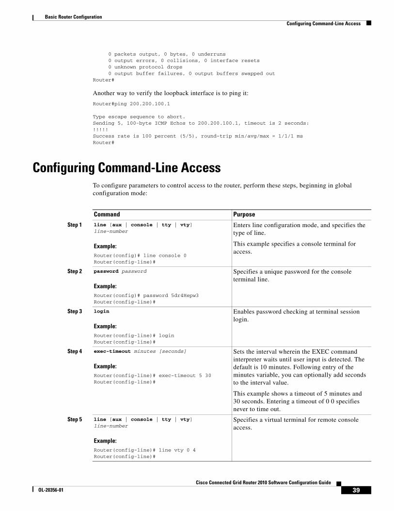
Basic Router ConfigurationConfiguring Command-Line Access
0 packets output, 0 bytes, 0 underruns 0 output errors, 0 collisions, 0 interface resets 0 unknown protocol drops 0 output buffer failures, 0 output buffers swapped outRouter#
Another way to verify the loopback interface is to ping it:
Router#ping 200.200.100.1
Type escape sequence to abort.Sending 5, 100-byte ICMP Echos to 200.200.100.1, timeout is 2 seconds:!!!!!Success rate is 100 percent (5/5), round-trip min/avg/max = 1/1/1 msRouter#
Configuring Command-Line AccessTo configure parameters to control access to the router, perform these steps, beginning in global configuration mode:
Command Purpose
Step 1 line [aux | console | tty | vty] line-number
Example:Router(config)# line console 0Router(config-line)#
Enters line configuration mode, and specifies the type of line.
This example specifies a console terminal for access.
Step 2 password password
Example:Router(config)# password 5dr4Hepw3Router(config-line)#
Specifies a unique password for the console terminal line.
Step 3 login
Example:Router(config-line)# loginRouter(config-line)#
Enables password checking at terminal session login.
Step 4 exec-timeout minutes [seconds]
Example:Router(config-line)# exec-timeout 5 30Router(config-line)#
Sets the interval wherein the EXEC command interpreter waits until user input is detected. The default is 10 minutes. Following entry of the minutes variable, you can optionally add seconds to the interval value.
This example shows a timeout of 5 minutes and 30 seconds. Entering a timeout of 0 0 specifies never to time out.
Step 5 line [aux | console | tty | vty] line-number
Example:Router(config-line)# line vty 0 4Router(config-line)#
Specifies a virtual terminal for remote console access.
39Cisco Connected Grid Router 2010 Software Configuration Guide
OL-20356-01
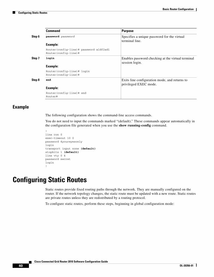
Basic Router ConfigurationConfiguring Static Routes
Example
The following configuration shows the command-line access commands.
You do not need to input the commands marked “(default).” These commands appear automatically in the configuration file generated when you use the show running-config command.
!line con 0exec-timeout 10 0password 4youreyesonlylogintransport input none (default)stopbits 1 (default)line vty 0 4password secretlogin!
Configuring Static RoutesStatic routes provide fixed routing paths through the network. They are manually configured on the router. If the network topology changes, the static route must be updated with a new route. Static routes are private routes unless they are redistributed by a routing protocol.
To configure static routes, perform these steps, beginning in global configuration mode:
Step 6 password password
Example:Router(config-line)# password aldf2ad1Router(config-line)#
Specifies a unique password for the virtual terminal line.
Step 7 login
Example:Router(config-line)# loginRouter(config-line)#
Enables password checking at the virtual terminal session login.
Step 8 end
Example:Router(config-line)# endRouter#
Exits line configuration mode, and returns to privileged EXEC mode.
Command Purpose
40Cisco Connected Grid Router 2010 Software Configuration Guide
OL-20356-01
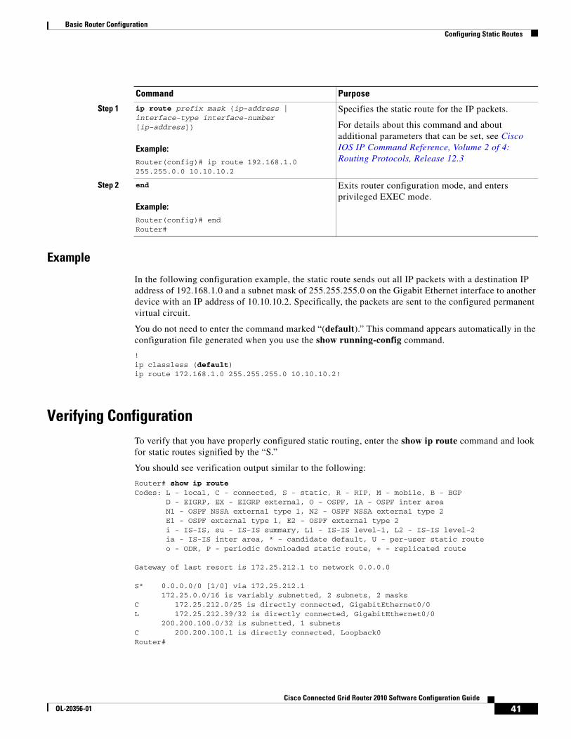
Basic Router ConfigurationConfiguring Static Routes
Example
In the following configuration example, the static route sends out all IP packets with a destination IP address of 192.168.1.0 and a subnet mask of 255.255.255.0 on the Gigabit Ethernet interface to another device with an IP address of 10.10.10.2. Specifically, the packets are sent to the configured permanent virtual circuit.
You do not need to enter the command marked “(default).” This command appears automatically in the configuration file generated when you use the show running-config command.
!ip classless (default)ip route 172.168.1.0 255.255.255.0 10.10.10.2!
Verifying ConfigurationTo verify that you have properly configured static routing, enter the show ip route command and look for static routes signified by the “S.”
You should see verification output similar to the following:
Router# show ip routeCodes: L - local, C - connected, S - static, R - RIP, M - mobile, B - BGP D - EIGRP, EX - EIGRP external, O - OSPF, IA - OSPF inter area N1 - OSPF NSSA external type 1, N2 - OSPF NSSA external type 2 E1 - OSPF external type 1, E2 - OSPF external type 2 i - IS-IS, su - IS-IS summary, L1 - IS-IS level-1, L2 - IS-IS level-2 ia - IS-IS inter area, * - candidate default, U - per-user static route o - ODR, P - periodic downloaded static route, + - replicated route
Gateway of last resort is 172.25.212.1 to network 0.0.0.0
S* 0.0.0.0/0 [1/0] via 172.25.212.1 172.25.0.0/16 is variably subnetted, 2 subnets, 2 masksC 172.25.212.0/25 is directly connected, GigabitEthernet0/0L 172.25.212.39/32 is directly connected, GigabitEthernet0/0 200.200.100.0/32 is subnetted, 1 subnetsC 200.200.100.1 is directly connected, Loopback0Router#
Command Purpose
Step 1 ip route prefix mask {ip-address | interface-type interface-number [ip-address]}
Example:Router(config)# ip route 192.168.1.0 255.255.0.0 10.10.10.2
Specifies the static route for the IP packets.
For details about this command and about additional parameters that can be set, see Cisco IOS IP Command Reference, Volume 2 of 4: Routing Protocols, Release 12.3
Step 2 end
Example:Router(config)# endRouter#
Exits router configuration mode, and enters privileged EXEC mode.
41Cisco Connected Grid Router 2010 Software Configuration Guide
OL-20356-01
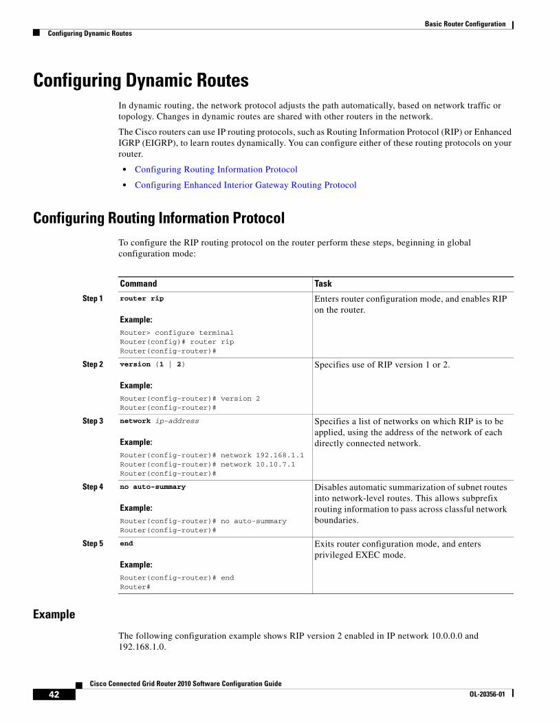
Basic Router ConfigurationConfiguring Dynamic Routes
Configuring Dynamic RoutesIn dynamic routing, the network protocol adjusts the path automatically, based on network traffic or topology. Changes in dynamic routes are shared with other routers in the network.
The Cisco routers can use IP routing protocols, such as Routing Information Protocol (RIP) or Enhanced IGRP (EIGRP), to learn routes dynamically. You can configure either of these routing protocols on your router.
• Configuring Routing Information Protocol
• Configuring Enhanced Interior Gateway Routing Protocol
Configuring Routing Information ProtocolTo configure the RIP routing protocol on the router perform these steps, beginning in global configuration mode:
Example
The following configuration example shows RIP version 2 enabled in IP network 10.0.0.0 and 192.168.1.0.
Command Task
Step 1 router rip
Example:Router> configure terminalRouter(config)# router ripRouter(config-router)#
Enters router configuration mode, and enables RIP on the router.
Step 2 version {1 | 2}
Example:Router(config-router)# version 2Router(config-router)#
Specifies use of RIP version 1 or 2.
Step 3 network ip-address
Example:Router(config-router)# network 192.168.1.1Router(config-router)# network 10.10.7.1Router(config-router)#
Specifies a list of networks on which RIP is to be applied, using the address of the network of each directly connected network.
Step 4 no auto-summary
Example:Router(config-router)# no auto-summaryRouter(config-router)#
Disables automatic summarization of subnet routes into network-level routes. This allows subprefix routing information to pass across classful network boundaries.
Step 5 end
Example:Router(config-router)# endRouter#
Exits router configuration mode, and enters privileged EXEC mode.
42Cisco Connected Grid Router 2010 Software Configuration Guide
OL-20356-01
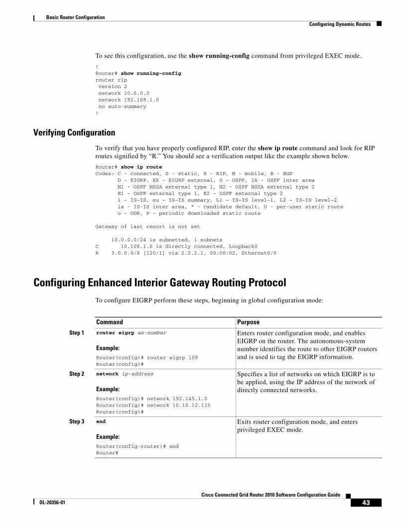
Basic Router ConfigurationConfiguring Dynamic Routes
To see this configuration, use the show running-config command from privileged EXEC mode.
!Router# show running-configrouter rip version 2 network 10.0.0.0 network 192.168.1.0 no auto-summary!
Verifying Configuration
To verify that you have properly configured RIP, enter the show ip route command and look for RIP routes signified by “R.” You should see a verification output like the example shown below.
Router# show ip routeCodes: C - connected, S - static, R - RIP, M - mobile, B - BGP D - EIGRP, EX - EIGRP external, O - OSPF, IA - OSPF inter area N1 - OSPF NSSA external type 1, N2 - OSPF NSSA external type 2 E1 - OSPF external type 1, E2 - OSPF external type 2 i - IS-IS, su - IS-IS summary, L1 - IS-IS level-1, L2 - IS-IS level-2 ia - IS-IS inter area, * - candidate default, U - per-user static route o - ODR, P - periodic downloaded static route
Gateway of last resort is not set
10.0.0.0/24 is subnetted, 1 subnetsC 10.108.1.0 is directly connected, Loopback0R 3.0.0.0/8 [120/1] via 2.2.2.1, 00:00:02, Ethernet0/0
Configuring Enhanced Interior Gateway Routing ProtocolTo configure EIGRP perform these steps, beginning in global configuration mode:
Command Purpose
Step 1 router eigrp as-number
Example:Router(config)# router eigrp 109Router(config)#
Enters router configuration mode, and enables EIGRP on the router. The autonomous-system number identifies the route to other EIGRP routers and is used to tag the EIGRP information.
Step 2 network ip-address
Example:Router(config)# network 192.145.1.0Router(config)# network 10.10.12.115Router(config)#
Specifies a list of networks on which EIGRP is to be applied, using the IP address of the network of directly connected networks.
Step 3 end
Example:Router(config-router)# endRouter#
Exits router configuration mode, and enters privileged EXEC mode.
43Cisco Connected Grid Router 2010 Software Configuration Guide
OL-20356-01
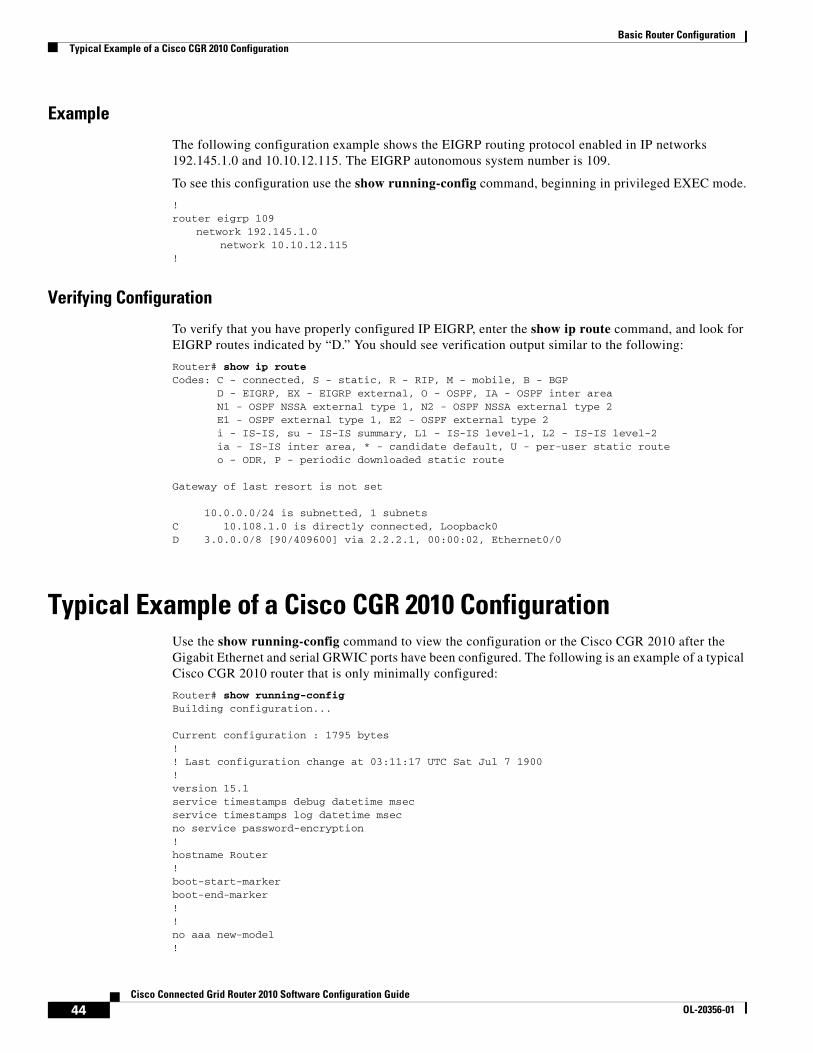
Basic Router ConfigurationTypical Example of a Cisco CGR 2010 Configuration
Example
The following configuration example shows the EIGRP routing protocol enabled in IP networks 192.145.1.0 and 10.10.12.115. The EIGRP autonomous system number is 109.
To see this configuration use the show running-config command, beginning in privileged EXEC mode.
!router eigrp 109
network 192.145.1.0network 10.10.12.115
!
Verifying Configuration
To verify that you have properly configured IP EIGRP, enter the show ip route command, and look for EIGRP routes indicated by “D.” You should see verification output similar to the following:
Router# show ip routeCodes: C - connected, S - static, R - RIP, M - mobile, B - BGP D - EIGRP, EX - EIGRP external, O - OSPF, IA - OSPF inter area N1 - OSPF NSSA external type 1, N2 - OSPF NSSA external type 2 E1 - OSPF external type 1, E2 - OSPF external type 2 i - IS-IS, su - IS-IS summary, L1 - IS-IS level-1, L2 - IS-IS level-2 ia - IS-IS inter area, * - candidate default, U - per-user static route o - ODR, P - periodic downloaded static route
Gateway of last resort is not set
10.0.0.0/24 is subnetted, 1 subnetsC 10.108.1.0 is directly connected, Loopback0D 3.0.0.0/8 [90/409600] via 2.2.2.1, 00:00:02, Ethernet0/0
Typical Example of a Cisco CGR 2010 ConfigurationUse the show running-config command to view the configuration or the Cisco CGR 2010 after the Gigabit Ethernet and serial GRWIC ports have been configured. The following is an example of a typical Cisco CGR 2010 router that is only minimally configured:
Router# show running-config Building configuration...
Current configuration : 1795 bytes!! Last configuration change at 03:11:17 UTC Sat Jul 7 1900!version 15.1service timestamps debug datetime msecservice timestamps log datetime msecno service password-encryption!hostname Router!boot-start-markerboot-end-marker!!no aaa new-model!
44Cisco Connected Grid Router 2010 Software Configuration Guide
OL-20356-01
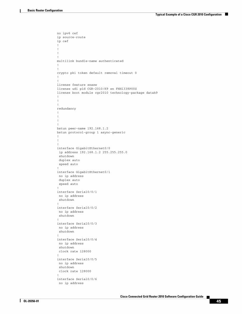
Basic Router ConfigurationTypical Example of a Cisco CGR 2010 Configuration
no ipv6 cefip source-routeip cef! !!!multilink bundle-name authenticated!!crypto pki token default removal timeout 0!!license feature snaswlicense udi pid CGR-2010/K9 sn FHH1338P00Slicense boot module cgr2010 technology-package datak9!!!redundancy!!!!bstun peer-name 192.168.1.2bstun protocol-group 1 async-generic! !!interface GigabitEthernet0/0 ip address 192.168.1.2 255.255.255.0 shutdown duplex auto speed auto!interface GigabitEthernet0/1 no ip address duplex auto speed auto!interface Serial0/0/1 no ip address shutdown!interface Serial0/0/2 no ip address shutdown!interface Serial0/0/3 no ip address shutdown!interface Serial0/0/4 no ip address shutdown clock rate 128000!interface Serial0/0/5 no ip address shutdown clock rate 128000!interface Serial0/0/6 no ip address
45Cisco Connected Grid Router 2010 Software Configuration Guide
OL-20356-01
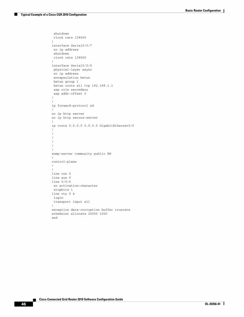
Basic Router ConfigurationTypical Example of a Cisco CGR 2010 Configuration
shutdown clock rate 128000!interface Serial0/0/7 no ip address shutdown clock rate 128000!interface Serial0/0/0 physical-layer async no ip address encapsulation bstun bstun group 1 bstun route all tcp 192.168.1.1 asp role secondary asp addr-offset 0!!ip forward-protocol nd!no ip http serverno ip http secure-server!ip route 0.0.0.0 0.0.0.0 GigabitEthernet0/0!!!!!!snmp-server community public RW! control-plane!!line con 0line aux 0line 0/0/0 no activation-character stopbits 1line vty 0 4 login transport input all!exception data-corruption buffer truncatescheduler allocate 20000 1000end
46Cisco Connected Grid Router 2010 Software Configuration Guide
OL-20356-01
Configuring Backup Data Lines and Remote Management
First Published: May 27, 2010, OL-20356-01Last Updated: October 25, 2017
The Cisco Connected Grid Router 2010 supports remote management and backup data connectivity. The following sections describe how to configure backup data lines and remote management:
• Configuring Backup Interfaces, page 47
• Configuring Dial Backup and Remote Management Through the Console Port or Auxiliary Port, page 49
Configuring Backup InterfacesThis section describes how to configure back up interfaces for failover redundancy when the network goes down.
Configuring Gigabit Ethernet Failover MediaCisco CGR 2010 routers have an SFP-GE port that supports either copper or fiber connections. Media can be configured for failover redundancy when the network goes down. To assign primary and secondary failover media on the SFP-GE port, perform these steps, beginning in EXEC mode.
Americas Headquarters:Cisco Systems, Inc., 170 West Tasman Drive, San Jose, CA 95134-1706 USA
© 2010 Cisco Systems, Inc. All rights reserved.
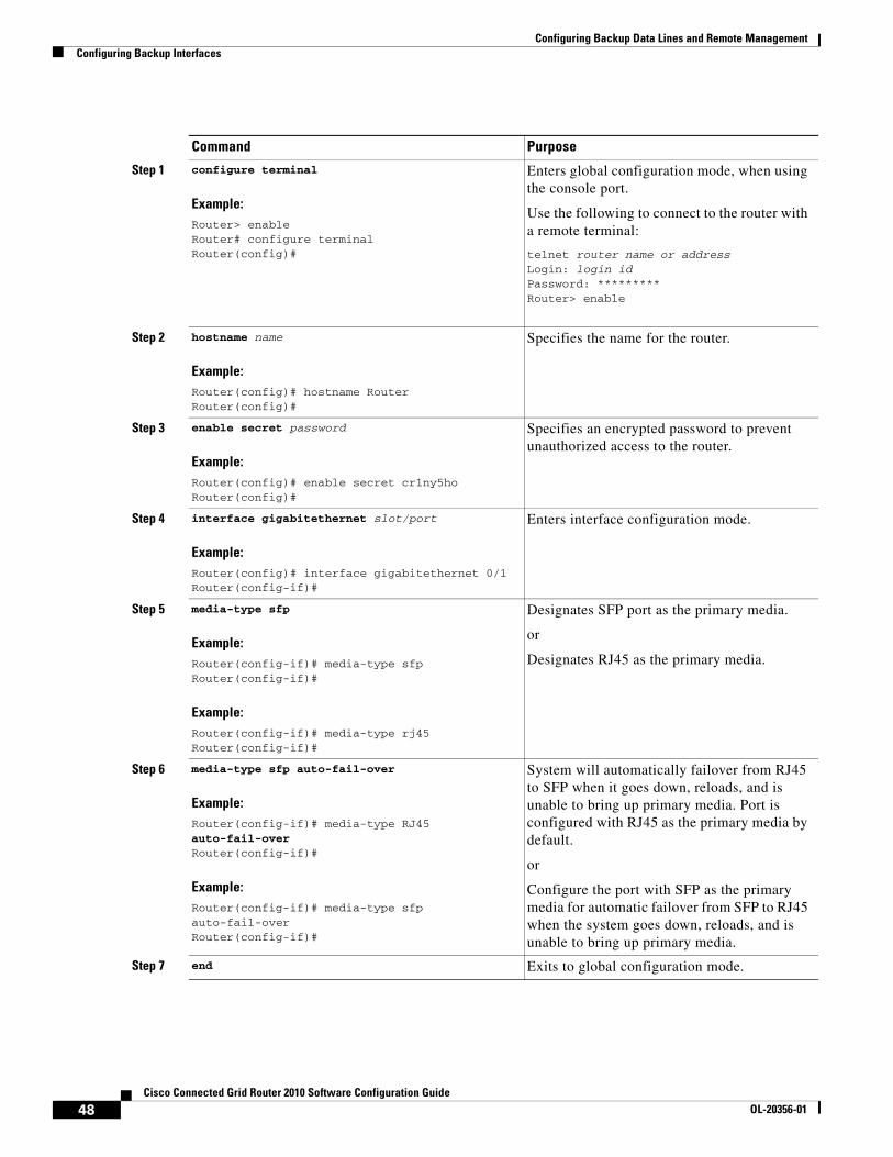
Configuring Backup Data Lines and Remote ManagementConfiguring Backup Interfaces
Command Purpose
Step 1 configure terminal
Example:Router> enableRouter# configure terminalRouter(config)#
Enters global configuration mode, when using the console port.
Use the following to connect to the router with a remote terminal:
telnet router name or addressLogin: login idPassword: *********Router> enable
Step 2 hostname name
Example:Router(config)# hostname RouterRouter(config)#
Specifies the name for the router.
Step 3 enable secret password
Example:Router(config)# enable secret cr1ny5hoRouter(config)#
Specifies an encrypted password to prevent unauthorized access to the router.
Step 4 interface gigabitethernet slot/port
Example:Router(config)# interface gigabitethernet 0/1Router(config-if)#
Enters interface configuration mode.
Step 5 media-type sfp
Example:Router(config-if)# media-type sfpRouter(config-if)#
Example:Router(config-if)# media-type rj45Router(config-if)#
Designates SFP port as the primary media.
or
Designates RJ45 as the primary media.
Step 6 media-type sfp auto-fail-over
Example:Router(config-if)# media-type RJ45 auto-fail-overRouter(config-if)#
Example:Router(config-if)# media-type sfp auto-fail-overRouter(config-if)#
System will automatically failover from RJ45 to SFP when it goes down, reloads, and is unable to bring up primary media. Port is configured with RJ45 as the primary media by default.
or
Configure the port with SFP as the primary media for automatic failover from SFP to RJ45 when the system goes down, reloads, and is unable to bring up primary media.
Step 7 end Exits to global configuration mode.
48Cisco Connected Grid Router 2010 Software Configuration Guide
OL-20356-01

Configuring Backup Data Lines and Remote ManagementConfiguring Dial Backup and Remote Management Through the Console Port or Auxiliary Port
Configuring Dial Backup and Remote Management Through the Console Port or Auxiliary Port
In dial backup, the switched circuit is used to provide backup service for another type of circuit, such as point-to-point or packet switching. The router is configured so that when a failure is detected on the primary circuit, the dial backup line is initiated. The dial backup line then supports the WAN connection until the primary circuit is restored. When this occurs, the dial backup connection is terminated.
A modem enables data to be transmitted over voice-grade telephone lines. At the source, digital signals are converted to a form suitable for transmission over analog communication facilities. At the destination, these analog signals are returned to their digital form. It is a simple modem-to-modem connection through a WAN.
When customer premises equipment, such as the Cisco Connected Grid Router 2010, are connected to an ISP, an IP address is dynamically assigned to the router, or the IP address is assigned by the router peer through the centrally managed function. The dial backup feature can be added to provide a failover route in case the primary line fails. The Cisco CGR 2010 can use the auxiliary port for dial backup and remote management.
The main WAN link of the Cisco CGR 2010 is the primary connection to the Internet service provider. A modem can serve as the dial backup that serves as a failover link for the Cisco CGR 2010 when the primary connection goes down. For remote management, the PC serves as dial-in access to allow changes or updates to Cisco IOS configurations.
To configure dial backup and remote management for the Cisco Connected Grid Router 2010, complete the following steps, beginning in global configuration mode:
SUMMARY STEPS
1. ip name-server server-address
2. ip dhcp pool name
3. exit
4. chat-script script-name expect-send
5. interface type number
6. exit
7. interface type number
8. dialer watch-group group-number
9. exit
10. ip nat inside source {list access-list-number} {interface type number | pool name} [overload]
11. ip route prefix mask {ip-address | interface-type interface-number [ip-address]}
12. access-list access-list-number {deny | permit} source [source-wildcard]
13. dialerwatch-list group-number {ip ip-address address-mask | delay route-check initial seconds}
14. line [aux | console | tty | vty] line-number [ending-line-number]
15. modem enable
16. exit
17. line [aux | console | tty | vty] line-number [ending-line-number]
18. flowcontrol {none | software [lock] [in | out] | hardware [in | out]}
49Cisco Connected Grid Router 2010 Software Configuration Guide
OL-20356-01

Configuring Backup Data Lines and Remote ManagementConfiguring Dial Backup and Remote Management Through the Console Port or Auxiliary Port
DETAILED STEPS
Command Purpose
Step 1 ip name-server server-address
Example:Router(config)# ip name-server 192.168.28.12
Enters your ISP DNS IP address.
Tip You may add multiple server addresses if available.
Step 2 ip dhcp pool name
Example:Router(config)# ip dhcp pool 1
Creates a DHCP address pool on the router and enters DHCP pool configuration mode. The name argument can be a string or an integer.
Configure the DHCP address pool. For sample commands that you can use in DHCP pool configuration mode, see the “Example” section on page 52.
Step 3 exit
Example:Router(config-dhcp)# exit
Exits DHCP pool configuration mode and enters global configuration mode.
Step 4 chat-script script-name expect-send
Example:Router(config)# chat-script Dialout ABORT ERROR ABORT BUSY ““ “AT” OK “ATDT 5555102 T” TIMEOUT 45 CONNECT \c
Configures a chat script for use in Dial-on-Demand Routing to give commands for dialing a modem and for logging in to remote systems. The defined script is used to place a call over a modem connected to the public switched telephone network.
Step 5 interface type number
Example:Router(config)# interface Async 1
Creates asynchronous interface and enters configuration mode for the asynchronous interface.
Configures the asynchronous interface. For sample commands that you can use in asynchronous interface configuration mode, see the “Example” section on page 52.
Step 6 exit
Example:Router(config-if)# exit
Exits interface configuration mode and enters global configuration mode.
Step 7 interface type number
Example:Router(config)# interface Dialer 3
Creates dialer interface and enters configuration mode for the dialer interface.
Step 8 dialer watch-group group-number
Example:Router(config-if)# dialer watch-group 1
Specifies the group number for the dialer watch list.
50Cisco Connected Grid Router 2010 Software Configuration Guide
OL-20356-01
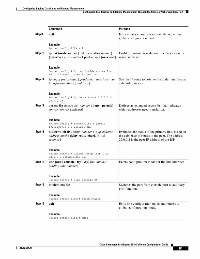
Configuring Backup Data Lines and Remote ManagementConfiguring Dial Backup and Remote Management Through the Console Port or Auxiliary Port
Step 9 exit
Example:Router(config-if)# exit
Exits interface configuration mode and enters global configuration mode.
Step 10 ip nat inside source {list access-list-number} {interface type number | pool name} [overload]
Example:Router(config)# ip nat inside source list 101 interface Dialer 3 overload
Enables dynamic translation of addresses on the inside interface.
Step 11 ip route prefix mask {ip-address | interface-type interface-number [ip-address]}
Example:Router(config)# ip route 0.0.0.0 0.0.0.0 22.0.0.2#
Sets the IP route to point to the dialer interface as a default gateway.
Step 12 access-list access-list-number {deny | permit} source [source-wildcard]
Example:Router(config)# access-list 1 permit 192.168.0.0 0.0.255.255 any
Defines an extended access list that indicates which addresses need translation.
Step 13 dialerwatch-list group-number {ip ip-address address-mask | delay route-check initial seconds}
Example:Router(config)# dialer watch-list 1 ip 22.0.0.2 255.255.255.255
Evaluates the status of the primary link, based on the existence of routes to the peer. The address 22.0.0.2 is the peer IP address of the ISP.
Step 14 line [aux | console | tty | vty] line-number [ending-line-number]
Example:Router(config)# line console 0#
Enters configuration mode for the line interface.
Step 15 modem enable
Example:Router(config-line)# modem enable
Switches the port from console port to auxiliary port function.
Step 16 exit
Example:Router(config-line)# exit
Exits line configuration mode and returns to global configuration mode.
Command Purpose
51Cisco Connected Grid Router 2010 Software Configuration Guide
OL-20356-01
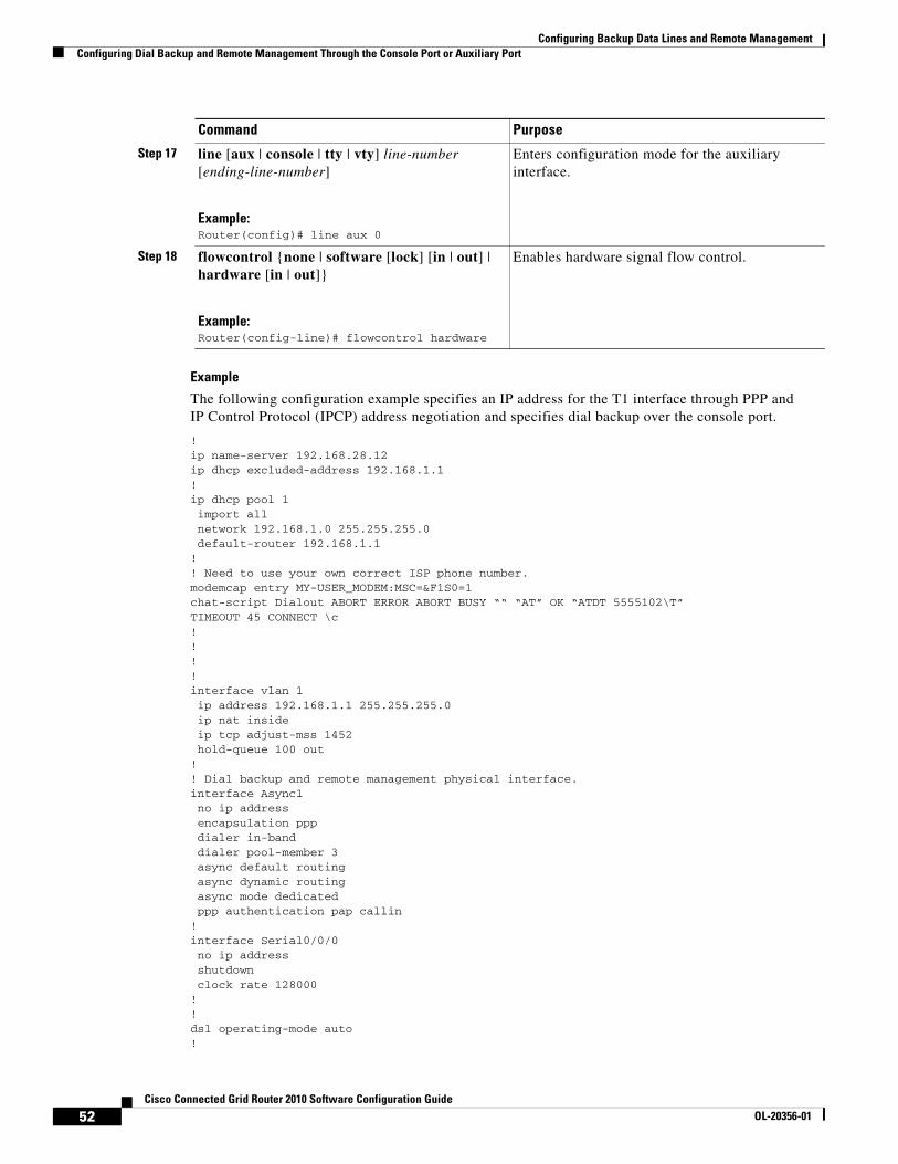
Configuring Backup Data Lines and Remote ManagementConfiguring Dial Backup and Remote Management Through the Console Port or Auxiliary Port
Example
The following configuration example specifies an IP address for the T1 interface through PPP and IP Control Protocol (IPCP) address negotiation and specifies dial backup over the console port.
!ip name-server 192.168.28.12ip dhcp excluded-address 192.168.1.1!ip dhcp pool 1 import all network 192.168.1.0 255.255.255.0 default-router 192.168.1.1!! Need to use your own correct ISP phone number.modemcap entry MY-USER_MODEM:MSC=&F1S0=1chat-script Dialout ABORT ERROR ABORT BUSY ““ “AT” OK “ATDT 5555102\T”TIMEOUT 45 CONNECT \c!!!!interface vlan 1 ip address 192.168.1.1 255.255.255.0 ip nat inside ip tcp adjust-mss 1452 hold-queue 100 out!! Dial backup and remote management physical interface.interface Async1 no ip address encapsulation ppp dialer in-band dialer pool-member 3 async default routing async dynamic routing async mode dedicated ppp authentication pap callin!interface Serial0/0/0 no ip address shutdown clock rate 128000!!dsl operating-mode auto!
Step 17 line [aux | console | tty | vty] line-number [ending-line-number]
Example:Router(config)# line aux 0
Enters configuration mode for the auxiliary interface.
Step 18 flowcontrol {none | software [lock] [in | out] | hardware [in | out]}
Example:Router(config-line)# flowcontrol hardware
Enables hardware signal flow control.
Command Purpose
52Cisco Connected Grid Router 2010 Software Configuration Guide
OL-20356-01
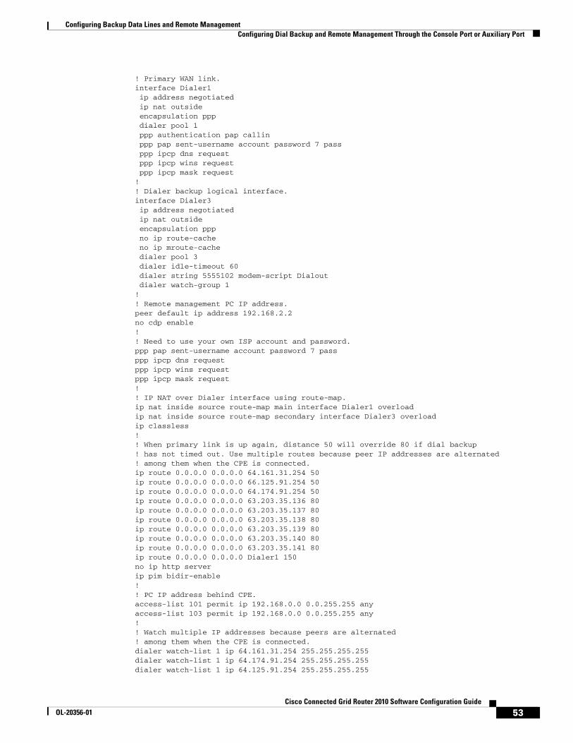
Configuring Backup Data Lines and Remote ManagementConfiguring Dial Backup and Remote Management Through the Console Port or Auxiliary Port
! Primary WAN link.interface Dialer1 ip address negotiated ip nat outside encapsulation ppp dialer pool 1 ppp authentication pap callin ppp pap sent-username account password 7 pass ppp ipcp dns request ppp ipcp wins request ppp ipcp mask request!! Dialer backup logical interface.interface Dialer3 ip address negotiated ip nat outside encapsulation ppp no ip route-cache no ip mroute-cache dialer pool 3 dialer idle-timeout 60 dialer string 5555102 modem-script Dialout dialer watch-group 1!! Remote management PC IP address.peer default ip address 192.168.2.2no cdp enable!! Need to use your own ISP account and password.ppp pap sent-username account password 7 passppp ipcp dns requestppp ipcp wins requestppp ipcp mask request!! IP NAT over Dialer interface using route-map.ip nat inside source route-map main interface Dialer1 overloadip nat inside source route-map secondary interface Dialer3 overloadip classless!! When primary link is up again, distance 50 will override 80 if dial backup ! has not timed out. Use multiple routes because peer IP addresses are alternated ! among them when the CPE is connected.ip route 0.0.0.0 0.0.0.0 64.161.31.254 50ip route 0.0.0.0 0.0.0.0 66.125.91.254 50ip route 0.0.0.0 0.0.0.0 64.174.91.254 50ip route 0.0.0.0 0.0.0.0 63.203.35.136 80ip route 0.0.0.0 0.0.0.0 63.203.35.137 80ip route 0.0.0.0 0.0.0.0 63.203.35.138 80ip route 0.0.0.0 0.0.0.0 63.203.35.139 80ip route 0.0.0.0 0.0.0.0 63.203.35.140 80ip route 0.0.0.0 0.0.0.0 63.203.35.141 80ip route 0.0.0.0 0.0.0.0 Dialer1 150no ip http serverip pim bidir-enable!! PC IP address behind CPE.access-list 101 permit ip 192.168.0.0 0.0.255.255 anyaccess-list 103 permit ip 192.168.0.0 0.0.255.255 any!! Watch multiple IP addresses because peers are alternated ! among them when the CPE is connected.dialer watch-list 1 ip 64.161.31.254 255.255.255.255dialer watch-list 1 ip 64.174.91.254 255.255.255.255dialer watch-list 1 ip 64.125.91.254 255.255.255.255
53Cisco Connected Grid Router 2010 Software Configuration Guide
OL-20356-01

Configuring Backup Data Lines and Remote ManagementConfiguring Dial Backup and Remote Management Through the Console Port or Auxiliary Port
!! Dial backup will kick in if primary link is not available ! 5 minutes after CPE starts up.dialer watch-list 1 delay route-check initial 300dialer-list 1 protocol ip permit!! Direct traffic to an interface only if the dialer is assigned an IP address.route-map main permit 10 match ip address 101 match interface Dialer1!route-map secondary permit 10 match ip address 103 match interface Dialer3!! Change console to aux function.line con 0 exec-timedout 0 0 modem enable stopbits 1line aux 0 exec-timeout 0 0 ! To enable and communicate with the external modem properly. script dialer Dialout modem InOut modem autoconfigure discovery transport input all stopbits 1 speed 115200 flowcontrol hardwareline vty 0 4 exec-timeout 0 0 password cisco login!scheduler max-task-time 5000end
54Cisco Connected Grid Router 2010 Software Configuration Guide
OL-20356-01
Upgrading the Cisco IOS Software
First Published: May 27, 2010, OL-20356-01Last Updated: October 25, 2017
This document describes how to upgrade the Cisco Internetworking Operating System (IOS) software image on the Cisco Connected Grid Router 2010.
Contents• Restrictions for Upgrading the System Image, page 55
• Information About Upgrading the System Image, page 56
• How to Upgrade the Cisco IOS Image, page 57
Restrictions for Upgrading the System ImageCisco CGR 2010 routers download images to new Advanced Capability CompactFlash (CF) memory cards. There are two slots available for this CF:
• PCMCIA
• USB
Note Legacy CF will not operate in Cisco CGR 2010 routers. When legacy CF is inserted, the following error message appears:WARNING: Unsupported compact flash detected. Use of this card during normal operation can impact and severely degrade performance of the system. Please use supported compact flash cards only.
• Cisco IOS images for the access point download images to CF embedded on the access point.
Americas Headquarters:Cisco Systems, Inc., 170 West Tasman Drive, San Jose, CA 95134-1706 USA
© 2010 Cisco Systems, Inc. All rights reserved.
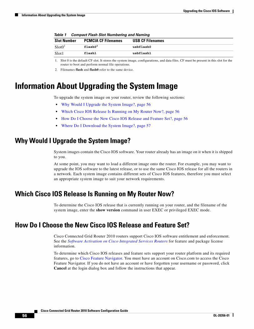
Upgrading the Cisco IOS SoftwareInformation About Upgrading the System Image
Table 1 Compact Flash Slot Numbering and Naming
Information About Upgrading the System ImageTo upgrade the system image on your router, review the following sections:
• Why Would I Upgrade the System Image?, page 56
• Which Cisco IOS Release Is Running on My Router Now?, page 56
• How Do I Choose the New Cisco IOS Release and Feature Set?, page 56
• Where Do I Download the System Image?, page 57
Why Would I Upgrade the System Image?System images contain the Cisco IOS software. Your router already has an image on it when it is shipped to you.
At some point, you may want to load a different image onto the router. For example, you may want to upgrade the IOS software to the latest release, or to use the same Cisco IOS release for all the routers in a network. Each system image contains different sets of Cisco IOS features, therefore you must select an appropriate system image to suit your network requirements.
Which Cisco IOS Release Is Running on My Router Now?To determine the Cisco IOS release that is currently running on your router, and the filename of the system image, enter the show version command in user EXEC or privileged EXEC mode.
How Do I Choose the New Cisco IOS Release and Feature Set?Cisco Connected Grid Router 2010 routers support Cisco IOS software entitlement and enforcement. See the Software Activation on Cisco Integrated Services Routers for feature and package license information.
To determine which Cisco IOS releases and feature sets support your router platform and its required features, go to Cisco Feature Navigator. You must have an account on Cisco.com to access the Cisco Feature Navigator. If you do not have an account or have forgotten your username or password, click Cancel at the login dialog box and follow the instructions that appear.
Slot Number PCMCIA CF Filenames USB CF Filenames
Slot01 flash02 usbflash0
Slot1 flash1 usbflash1
1. Slot 0 is the default CF slot. It stores the system image, configurations, and data files. CF must be present in this slot for the router to boot and perform normal file operations.
2. Filenames flash and flash0 refer to the same device.
56Cisco Connected Grid Router 2010 Software Configuration Guide
OL-20356-01
Upgrading the Cisco IOS SoftwareHow to Upgrade the Cisco IOS Image
Where Do I Download the System Image?To download a system image, you must have an account on Cisco.com to gain access to the following websites. If you do not have an account or have forgotten your username or password, click Cancel at the login dialog box, and follow the instructions that appear.
If you know which Cisco IOS release and feature set you want to download, go to the Download Software website.
If you want more information about downloading software, see Loading and Managing System Images.
How to Upgrade the Cisco IOS ImageThis section provides information about upgrading the Cisco IOS image on the router and Cisco IOS image on the access point.
Router Upgrade
• Saving Backup Copies of Your Old System Image and Configuration, page 57
• DRAM Size and the New System Image, page 59
• Ensuring Adequate Flash Memory for the New System Image, page 59
• Copying the System Image into Flash Memory, page 62
• Loading the New System Image, page 67
• Saving Backup Copies of Your New System Image and Configuration, page 71
Saving Backup Copies of Your Old System Image and ConfigurationTo avoid unexpected downtime if you encounter serious problems using your new system image or startup configuration, we recommend that you save backup copies of your current startup configuration file and Cisco IOS software system image file on a server.
For more detailed information, see the “Managing Configuration Files” chapter and the “Loading and Maintaining System Images” chapter of Cisco IOS Configuration Fundamentals Configuration Guide, Release 15.0.
To save backup copies of the startup configuration file and the system image file, complete the following steps:
SUMMARY STEPS
1. enable
2. copy nvram:startup-config {ftp: | rcp: | tftp:}
3. dir flash:
4. copy flash: {ftp: | rcp: | tftp:}
57Cisco Connected Grid Router 2010 Software Configuration Guide
OL-20356-01
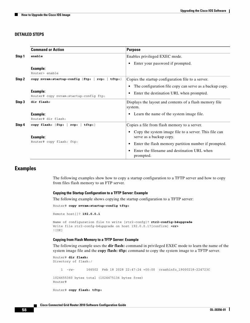
Upgrading the Cisco IOS SoftwareHow to Upgrade the Cisco IOS Image
DETAILED STEPS
Examples
The following examples show how to copy a startup configuration to a TFTP server and how to copy from files flash memory to an FTP server.
Copying the Startup Configuration to a TFTP Server: Example
The following example shows copying the startup configuration to a TFTP server:
Router# copy nvram:startup-config tftp:
Remote host[]? 192.0.0.1
Name of configuration file to write [rtr2-confg]? rtr2-config-b4upgrade Write file rtr2-confg-b4upgrade on host 192.0.0.1?[confirm] <cr> ![OK]
Copying from Flash Memory to a TFTP Server: Example
The following example uses the dir flash: command in privileged EXEC mode to learn the name of the system image file and the copy flash: tftp: command to copy the system image to a TFTP server.
Router# dir flash:Directory of flash:/
1 -rw- 166502 Feb 18 2028 22:47:24 +00:00 crashinfo_19000218-224723C
1024655360 bytes total (1024475136 bytes free)Router#
Router# copy flash: tftp:
Command or Action Purpose
Step 1 enable
Example:Router> enable
Enables privileged EXEC mode.
• Enter your password if prompted.
Step 2 copy nvram:startup-config {ftp: | rcp: | tftp:}
Example:Router# copy nvram:startup-config ftp:
Copies the startup configuration file to a server.
• The configuration file copy can serve as a backup copy.
• Enter the destination URL when prompted.
Step 3 dir flash:
Example:Router# dir flash:
Displays the layout and contents of a flash memory file system.
• Learn the name of the system image file.
Step 4 copy flash: {ftp: | rcp: | tftp:}
Example:Router# copy flash: ftp:
Copies a file from flash memory to a server.
• Copy the system image file to a server. This file can serve as a backup copy.
• Enter the flash memory partition number if prompted.
• Enter the filename and destination URL when prompted.
58Cisco Connected Grid Router 2010 Software Configuration Guide
OL-20356-01
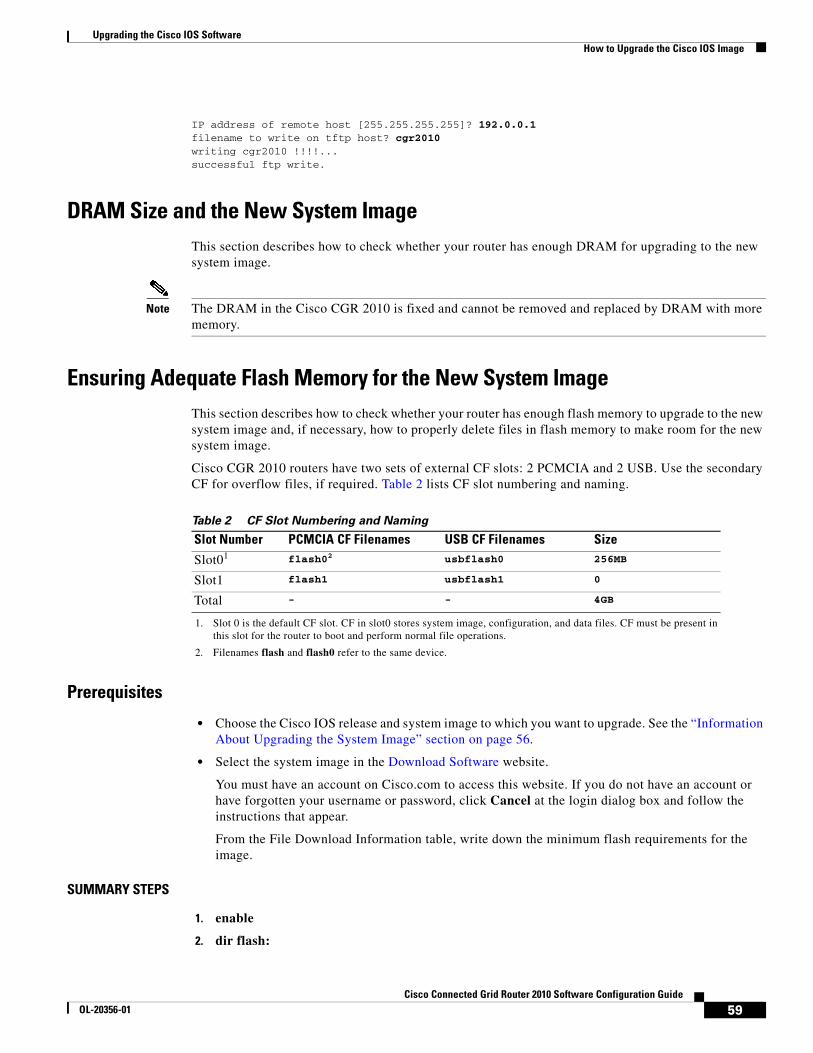
Upgrading the Cisco IOS SoftwareHow to Upgrade the Cisco IOS Image
IP address of remote host [255.255.255.255]? 192.0.0.1 filename to write on tftp host? cgr2010writing cgr2010 !!!!...successful ftp write.
DRAM Size and the New System ImageThis section describes how to check whether your router has enough DRAM for upgrading to the new system image.
Note The DRAM in the Cisco CGR 2010 is fixed and cannot be removed and replaced by DRAM with more memory.
Ensuring Adequate Flash Memory for the New System ImageThis section describes how to check whether your router has enough flash memory to upgrade to the new system image and, if necessary, how to properly delete files in flash memory to make room for the new system image.
Cisco CGR 2010 routers have two sets of external CF slots: 2 PCMCIA and 2 USB. Use the secondary CF for overflow files, if required. Table 2 lists CF slot numbering and naming.
Table 2 CF Slot Numbering and Naming
Prerequisites
• Choose the Cisco IOS release and system image to which you want to upgrade. See the “Information About Upgrading the System Image” section on page 56.
• Select the system image in the Download Software website.
You must have an account on Cisco.com to access this website. If you do not have an account or have forgotten your username or password, click Cancel at the login dialog box and follow the instructions that appear.
From the File Download Information table, write down the minimum flash requirements for the image.
SUMMARY STEPS
1. enable
2. dir flash:
Slot Number PCMCIA CF Filenames USB CF Filenames Size
Slot01 flash02 usbflash0 256MB
Slot1 flash1 usbflash1 0
Total - - 4GB
1. Slot 0 is the default CF slot. CF in slot0 stores system image, configuration, and data files. CF must be present in this slot for the router to boot and perform normal file operations.
2. Filenames flash and flash0 refer to the same device.
59Cisco Connected Grid Router 2010 Software Configuration Guide
OL-20356-01

Upgrading the Cisco IOS SoftwareHow to Upgrade the Cisco IOS Image
3. From the displayed output of the dir flash: command, compare the number of bytes available to the minimum flash requirements for the new system image.
a. If the available memory is equal to or greater than the new system image’s minimum flash requirements, proceed to the “Copying the System Image into Flash Memory” section on page 62.
b. If the available memory is less than the new system image’s minimum flash requirements, proceed to Step 4.
4. From the displayed output of the dir flash: command, compare the number of bytes total to the size of the system image to which you want to upgrade.
a. If the total memory is less than the new system image’s minimum flash requirements, you cannot upgrade your compact flash memory card because the DRAM is fixed. You must delete files in flash memory to make room for the new system image.
Note The DRAM in the Cisco CGR 2010 router is fixed and cannot be removed and replaced by DRAM with more memory.
b. If the total memory is equal to or greater than the new system image’s minimum flash requirements, proceed to Step 5.
5. Enter the dir /all flash: command.
6. From the displayed output of the dir /all flash: command, write down the names and directory locations of the files that you can delete.
7. (Optional) Enter the copy flash: {tftp | rcp} command.
8. (Optional) Repeat Step 7 for each file that you identified in Step 6.
9. Enter the delete flash:directory-path/filename command.
10. Repeat Step 9 for each file that you identified in Step 6.
11. Enter the dir flash:[partition-number:] command.
12. From the displayed output of the dir flash: command, compare the number of bytes available to the size of the system image to which you want to upgrade.
a. If the available memory is less than the new system image’s minimum flash requirements, then you cannot download the new image.
b. If the available memory is equal to or greater than the new system image’s minimum flash requirements, proceed to the “Copying the System Image into Flash Memory” section on page 62.
DETAILED STEPS
Step 1 Use the enable command to enter privileged EXEC mode. Enter your password if prompted. For example:
Router> enable Password:Router#
Step 2 Use the dir flash: command to display the layout and contents of flash memory:
Router# dir flash:
Directory of flash:/
60Cisco Connected Grid Router 2010 Software Configuration Guide
OL-20356-01

Upgrading the Cisco IOS SoftwareHow to Upgrade the Cisco IOS Image
1 -rw- 166502 Feb 18 2028 22:47:24 +00:00 crashinfo_19000218-224723C
1024655360 bytes total (1024475136 bytes free)
Step 3 From the displayed output of the dir flash: command, compare the number of bytes available to the minimum flash requirements for the new system image.
• If the available memory is equal to or greater than the new system image’s minimum flash requirements, proceed to the “Copying the System Image into Flash Memory” section on page 62.
• If the available memory is less than the new system image’s minimum flash requirements, proceed to Step 4.
Step 4 From the displayed output of the dir flash: command, compare the number of bytes total to the size of the system image to which you want to upgrade.
• If the total memory is less than the new system image’s minimum flash requirements, you cannot upgrade your compact flash memory card because the DRAM is fixed. You must delete files in flash memory to make room for the new system image.
• If the total memory is equal to or greater than the new system image’s minimum flash requirements, proceed to Step 5.
Step 5 Enter the dir /all flash: command to display a list of all files and directories in flash memory:
Router# dir /all flash:
Directory of flash:/
1 -rw- 166502 Feb 18 2028 22:47:24 +00:00 crashinfo_19000218-224723C
1024655360 bytes total (1024475136 bytes free)Router#
Step 6 From the displayed output of the dir /all flash: command, write down the names and directory locations of the files that you can delete. If you cannot delete any files, you cannot download the new image.
Note The DRAM in the Cisco CGR 2010 router is fixed and cannot be removed and replaced by DRAM with more memory.
Note Do not delete the system image that the router already uses. If you are not sure which files can be safely deleted, either consult your network administrator. You cannot upgrade your compact flash memory card to a size that can accommodate both the existing files and the new system image.
Step 7 (Optional) Enter the copy flash:{tftp | rcp} to copy a file to a server before deleting the file from flash memory. When prompted, enter the filename and the server’s hostname or IP address:
Router# copy flash tftp
Step 8 (Optional) Repeat Step 7 for each file that you identified in Step 6.
Step 9 Enter the delete flash:directory-path/filename command to delete a file in flash memory:
Router# delete flash:c29xx.tmp
Delete filename [cgr2010.tmp]? <cr> Delete flash:cgr2010.tmp? [confirm] <cr>
61Cisco Connected Grid Router 2010 Software Configuration Guide
OL-20356-01
Upgrading the Cisco IOS SoftwareHow to Upgrade the Cisco IOS Image
Step 10 Repeat Step 9 for each file that you identified in Step 6.
Step 11 Enter the dir flash: command to display the layout and contents of flash memory.
Step 12 From the displayed output of the dir flash: command, compare the number of bytes available to the size of the system image to which you want to upgrade.
• If the available memory is less than the new system image’s minimum flash requirements you cannot download the new image.
• If the available memory is equal to or greater than the new system image’s minimum flash requirements, proceed to the “Copying the System Image into Flash Memory” section on page 62.
What to Do Next
Proceed to the “Copying the System Image into Flash Memory” section on page 62.
Copying the System Image into Flash MemoryThis section describes how to copy the system image into the compact flash memory card for your router. Choose one of the following methods:
• Using TFTP or Remote Copy Protocol to Copy the System Image into Flash Memory, page 62
• Using the ROM Monitor to Copy the System Image over a Network, page 64
Using TFTP or Remote Copy Protocol to Copy the System Image into Flash Memory
This section describes how to use TFTP or Remote Copy Protocol (RCP) to upgrade the system image. This is the recommended and most common method of upgrading the system image.
Prerequisites
• Install a TFTP server or an RCP server application on a TCP/IP-ready workstation or PC. Many third-party vendors provide free TFTP server software, which you can find by searching for “TFTP server” in a web search engine.
If you use TFTP:
– Configure the TFTP application to operate as a TFTP server, not a TFTP client.
– Specify the outbound file directory to which you will download and store the system image.
• Download the new Cisco IOS software image into the workstation or PC. See the “Where Do I Download the System Image?” section on page 57.
• Establish a console session to the router. We recommend that you connect your PC directly to the router console port. See the hardware installation guide that shipped with your router.
• Verify that the TFTP or RCP server has IP connectivity to the router. If you cannot successfully ping between the TFTP or RCP server and the router, do one of the following:
– Configure a default gateway on the router.
– Make sure that the server and the router each have an IP address in the same network or subnet. See the tech note, Determining IP Addresses: Frequently Asked Questions.
62Cisco Connected Grid Router 2010 Software Configuration Guide
OL-20356-01
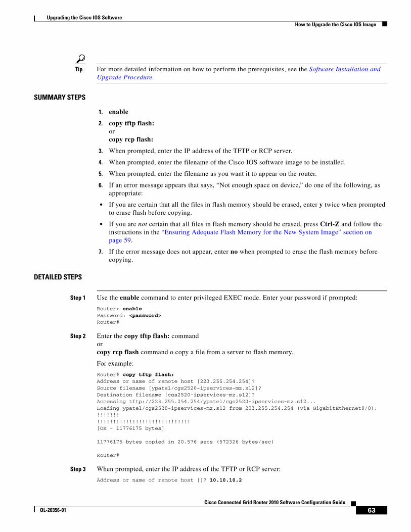
Upgrading the Cisco IOS SoftwareHow to Upgrade the Cisco IOS Image
Tip For more detailed information on how to perform the prerequisites, see the Software Installation and Upgrade Procedure.
SUMMARY STEPS
1. enable
2. copy tftp flash: orcopy rcp flash:
3. When prompted, enter the IP address of the TFTP or RCP server.
4. When prompted, enter the filename of the Cisco IOS software image to be installed.
5. When prompted, enter the filename as you want it to appear on the router.
6. If an error message appears that says, “Not enough space on device,” do one of the following, as appropriate:
• If you are certain that all the files in flash memory should be erased, enter y twice when prompted to erase flash before copying.
• If you are not certain that all files in flash memory should be erased, press Ctrl-Z and follow the instructions in the “Ensuring Adequate Flash Memory for the New System Image” section on page 59.
7. If the error message does not appear, enter no when prompted to erase the flash memory before copying.
DETAILED STEPS
Step 1 Use the enable command to enter privileged EXEC mode. Enter your password if prompted:
Router> enable Password: <password> Router#
Step 2 Enter the copy tftp flash: commandorcopy rcp flash command o copy a file from a server to flash memory.
For example:
Router# copy tftp flash: Address or name of remote host [223.255.254.254]? Source filename [ypatel/cgs2520-ipservices-mz.s12]? Destination filename [cgs2520-ipservices-mz.s12]? Accessing tftp://223.255.254.254/ypatel/cgs2520-ipservices-mz.s12...Loading ypatel/cgs2520-ipservices-mz.s12 from 223.255.254.254 (via GigabitEthernet0/0): !!!!!!!!!!!!!!!!!!!!!!!!!!!!!!!!!!!![OK - 11776175 bytes]
11776175 bytes copied in 20.576 secs (572326 bytes/sec)
Router#
Step 3 When prompted, enter the IP address of the TFTP or RCP server:
Address or name of remote host []? 10.10.10.2
63Cisco Connected Grid Router 2010 Software Configuration Guide
OL-20356-01
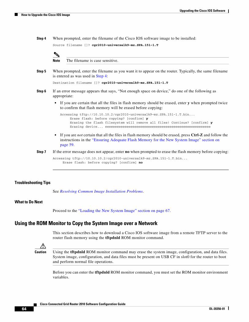
Upgrading the Cisco IOS SoftwareHow to Upgrade the Cisco IOS Image
Step 4 When prompted, enter the filename of the Cisco IOS software image to be installed:
Source filename []? cgr2010-universalk9-mz.SPA.151-1.T
Note The filename is case sensitive.
Step 5 When prompted, enter the filename as you want it to appear on the router. Typically, the same filename is entered as was used in Step 4:
Destination filename []? cgr2010-universalk9-mz.SPA.151-1.T
Step 6 If an error message appears that says, “Not enough space on device,” do one of the following as appropriate:
• If you are certain that all the files in flash memory should be erased, enter y when prompted twice to confirm that flash memory will be erased before copying:
Accessing tftp://10.10.10.2/cgr2010-universalk9-mz.SPA.151-1.T.bin... Erase flash: before copying? [confirm] y Erasing the flash filesystem will remove all files! Continue? [confirm] y Erasing device... eeeeeeeeeeeeeeeeeeeeeeeeeeeeeeeeeeeeeeeeeeeeeeeeeeeeee
• If you are not certain that all the files in flash memory should be erased, press Ctrl-Z and follow the instructions in the “Ensuring Adequate Flash Memory for the New System Image” section on page 59.
Step 7 If the error message does not appear, enter no when prompted to erase the flash memory before copying:
Accessing tftp://10.10.10.2/cgr2010-universalk9-mz.SPA.151-1.T.bin... Erase flash: before copying? [confirm] no
Troubleshooting Tips
See Resolving Common Image Installation Problems.
What to Do Next
Proceed to the “Loading the New System Image” section on page 67.
Using the ROM Monitor to Copy the System Image over a Network
This section describes how to download a Cisco IOS software image from a remote TFTP server to the router flash memory using the tftpdnld ROM monitor command.
Caution Using the tftpdnld ROM monitor command may erase the system image, configuration, and data files. System image, configuration, and data files must be present on USB CF in slot0 for the router to boot and perform normal file operations.
Before you can enter the tftpdnld ROM monitor command, you must set the ROM monitor environment variables.
64Cisco Connected Grid Router 2010 Software Configuration Guide
OL-20356-01
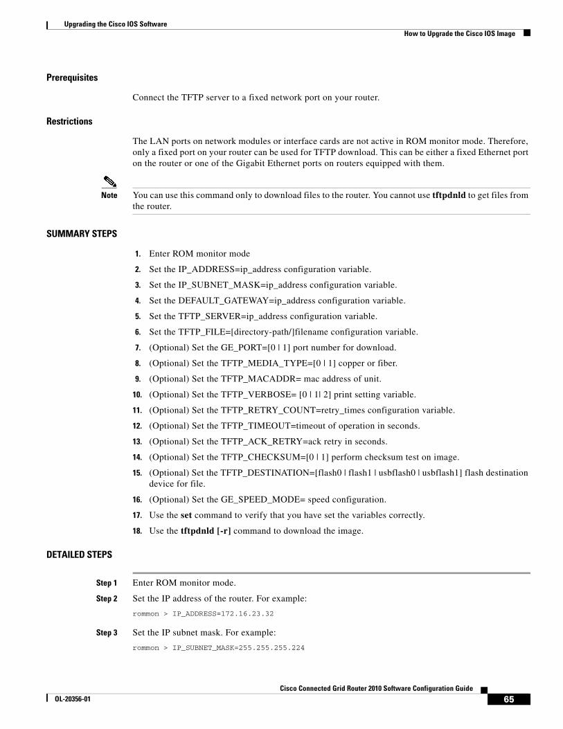
Upgrading the Cisco IOS SoftwareHow to Upgrade the Cisco IOS Image
Prerequisites
Connect the TFTP server to a fixed network port on your router.
Restrictions
The LAN ports on network modules or interface cards are not active in ROM monitor mode. Therefore, only a fixed port on your router can be used for TFTP download. This can be either a fixed Ethernet port on the router or one of the Gigabit Ethernet ports on routers equipped with them.
Note You can use this command only to download files to the router. You cannot use tftpdnld to get files from the router.
SUMMARY STEPS
1. Enter ROM monitor mode
2. Set the IP_ADDRESS=ip_address configuration variable.
3. Set the IP_SUBNET_MASK=ip_address configuration variable.
4. Set the DEFAULT_GATEWAY=ip_address configuration variable.
5. Set the TFTP_SERVER=ip_address configuration variable.
6. Set the TFTP_FILE=[directory-path/]filename configuration variable.
7. (Optional) Set the GE_PORT=[0 | 1] port number for download.
8. (Optional) Set the TFTP_MEDIA_TYPE=[0 | 1] copper or fiber.
9. (Optional) Set the TFTP_MACADDR= mac address of unit.
10. (Optional) Set the TFTP_VERBOSE= [0 | 1| 2] print setting variable.
11. (Optional) Set the TFTP_RETRY_COUNT=retry_times configuration variable.
12. (Optional) Set the TFTP_TIMEOUT=timeout of operation in seconds.
13. (Optional) Set the TFTP_ACK_RETRY=ack retry in seconds.
14. (Optional) Set the TFTP_CHECKSUM=[0 | 1] perform checksum test on image.
15. (Optional) Set the TFTP_DESTINATION=[flash0 | flash1 | usbflash0 | usbflash1] flash destination device for file.
16. (Optional) Set the GE_SPEED_MODE= speed configuration.
17. Use the set command to verify that you have set the variables correctly.
18. Use the tftpdnld [-r] command to download the image.
DETAILED STEPS
Step 1 Enter ROM monitor mode.
Step 2 Set the IP address of the router. For example:
rommon > IP_ADDRESS=172.16.23.32
Step 3 Set the IP subnet mask. For example:
rommon > IP_SUBNET_MASK=255.255.255.224
65Cisco Connected Grid Router 2010 Software Configuration Guide
OL-20356-01
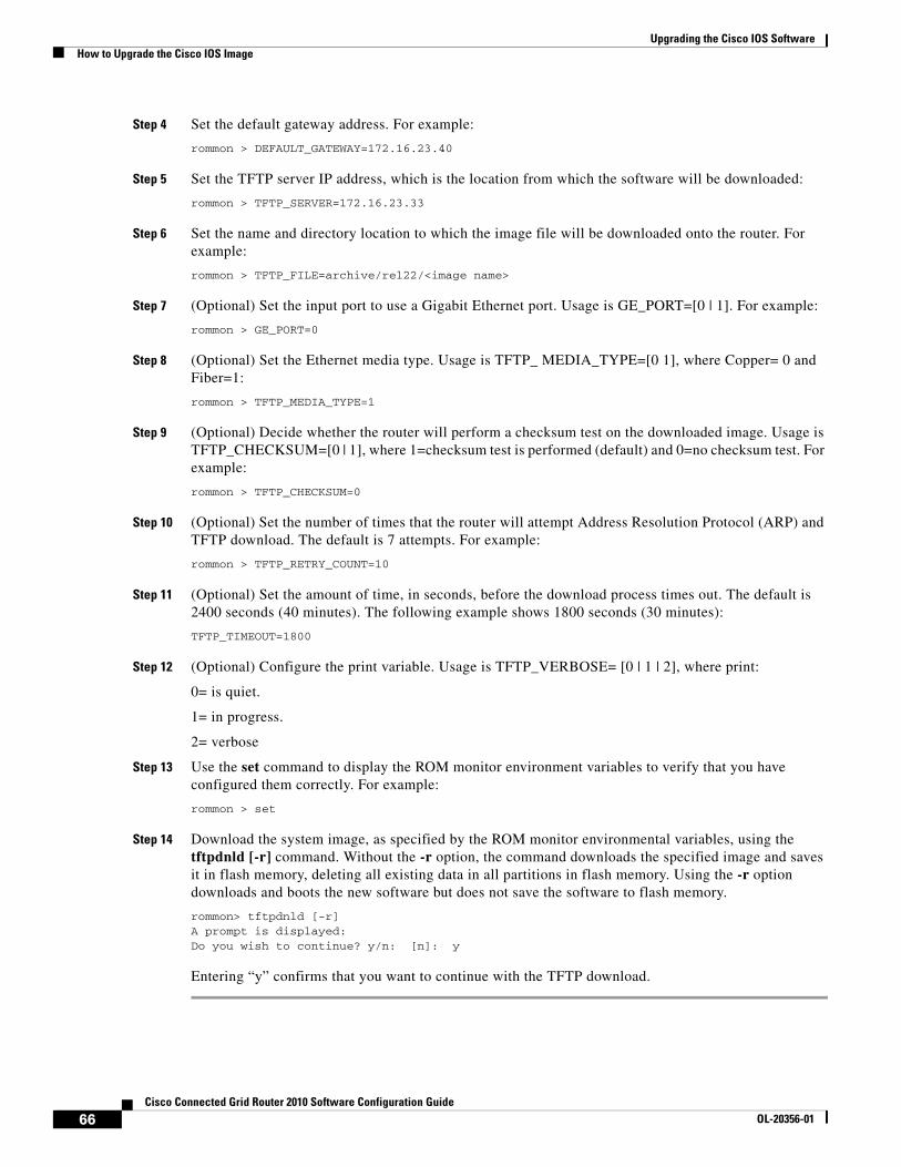
Upgrading the Cisco IOS SoftwareHow to Upgrade the Cisco IOS Image
Step 4 Set the default gateway address. For example:
rommon > DEFAULT_GATEWAY=172.16.23.40
Step 5 Set the TFTP server IP address, which is the location from which the software will be downloaded:
rommon > TFTP_SERVER=172.16.23.33
Step 6 Set the name and directory location to which the image file will be downloaded onto the router. For example:
rommon > TFTP_FILE=archive/rel22/<image name>
Step 7 (Optional) Set the input port to use a Gigabit Ethernet port. Usage is GE_PORT=[0 | 1]. For example:
rommon > GE_PORT=0
Step 8 (Optional) Set the Ethernet media type. Usage is TFTP_ MEDIA_TYPE=[0 1], where Copper= 0 and Fiber=1:
rommon > TFTP_MEDIA_TYPE=1
Step 9 (Optional) Decide whether the router will perform a checksum test on the downloaded image. Usage is TFTP_CHECKSUM=[0 | 1], where 1=checksum test is performed (default) and 0=no checksum test. For example:
rommon > TFTP_CHECKSUM=0
Step 10 (Optional) Set the number of times that the router will attempt Address Resolution Protocol (ARP) and TFTP download. The default is 7 attempts. For example:
rommon > TFTP_RETRY_COUNT=10
Step 11 (Optional) Set the amount of time, in seconds, before the download process times out. The default is 2400 seconds (40 minutes). The following example shows 1800 seconds (30 minutes):
TFTP_TIMEOUT=1800
Step 12 (Optional) Configure the print variable. Usage is TFTP_VERBOSE= [0 | 1 | 2], where print:
0= is quiet.
1= in progress.
2= verbose
Step 13 Use the set command to display the ROM monitor environment variables to verify that you have configured them correctly. For example:
rommon > set
Step 14 Download the system image, as specified by the ROM monitor environmental variables, using the tftpdnld [-r] command. Without the -r option, the command downloads the specified image and saves it in flash memory, deleting all existing data in all partitions in flash memory. Using the -r option downloads and boots the new software but does not save the software to flash memory.
rommon> tftpdnld [-r] A prompt is displayed:Do you wish to continue? y/n: [n]: y
Entering “y” confirms that you want to continue with the TFTP download.
66Cisco Connected Grid Router 2010 Software Configuration Guide
OL-20356-01
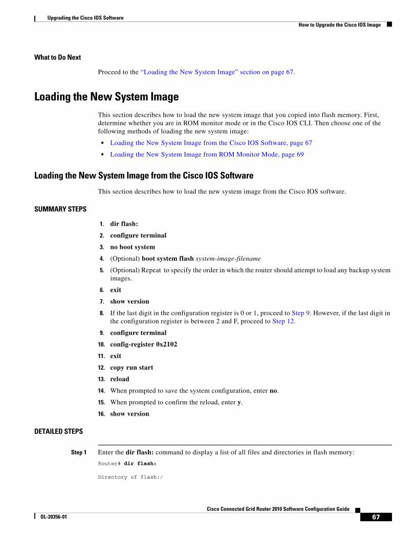
Upgrading the Cisco IOS SoftwareHow to Upgrade the Cisco IOS Image
What to Do Next
Proceed to the “Loading the New System Image” section on page 67.
Loading the New System ImageThis section describes how to load the new system image that you copied into flash memory. First, determine whether you are in ROM monitor mode or in the Cisco IOS CLI. Then choose one of the following methods of loading the new system image:
• Loading the New System Image from the Cisco IOS Software, page 67
• Loading the New System Image from ROM Monitor Mode, page 69
Loading the New System Image from the Cisco IOS Software
This section describes how to load the new system image from the Cisco IOS software.
SUMMARY STEPS
1. dir flash:
2. configure terminal
3. no boot system
4. (Optional) boot system flash system-image-filename
5. (Optional) Repeat to specify the order in which the router should attempt to load any backup system images.
6. exit
7. show version
8. If the last digit in the configuration register is 0 or 1, proceed to Step 9. However, if the last digit in the configuration register is between 2 and F, proceed to Step 12.
9. configure terminal
10. config-register 0x2102
11. exit
12. copy run start
13. reload
14. When prompted to save the system configuration, enter no.
15. When prompted to confirm the reload, enter y.
16. show version
DETAILED STEPS
Step 1 Enter the dir flash: command to display a list of all files and directories in flash memory:
Router# dir flash:
Directory of flash:/
67Cisco Connected Grid Router 2010 Software Configuration Guide
OL-20356-01

Upgrading the Cisco IOS SoftwareHow to Upgrade the Cisco IOS Image
3 -rw- 6458388 Mar 01 1993 00:00:58 c38xx.tmp 1580 -rw- 6462268 Mar 06 1993 06:14:02 c38xx-ata
63930368 bytes total (51007488 bytes free)
Note Determine whether the new system image is the first file or the only file listed in the dir flash command output ( is not required if it is the first file or only file listed).
Step 2 Enter the configure terminal command to enter global configuration mode:
Router# configure terminal
Router(config)#
Step 3 Enter the no boot system command to delete all entries in the bootable image list, which specifies the order in which the router attempts to load the system images at the next system reload or power cycle:
Router(config)# no boot system
Step 4 If the new system image is the first file or the only file displayed in the dir flash: command output, you do not need to perform the following step.
Enter the boot system flash system-image-filename command to load the new system image after the next system reload or power cycle. For example:
Router(config)# boot system flash cgr2010-universalk9-mz.SPA.151-1.T.bin
Step 5 (Optional) Repeat to specify the order in which the router should attempt to load any backup system images.
Step 6 Enter the exit command to exit global configuration mode:
Router(config)# exit Router#
Step 7 Enter the show version command to display the configuration register setting:
Router# show version
Cisco Internetwork Operating System Software...Configuration register is 0x0
Router#
Step 8 If the last digit in the configuration register is 0 or 1, proceed to Step 9. However, if the last digit in the configuration register is between 2 and F, proceed to Step 12.
Step 9 Enter the configure terminal command to enter global configuration mode:
Router# configure terminal
Router(config)#
Step 10 Enter the config-register 0x2102 command to set the configuration register so that, after the next system reload or power cycle, the router loads a system image from the boot system commands in the startup configuration file:
Router(config)# config-register 0x2102
68Cisco Connected Grid Router 2010 Software Configuration Guide
OL-20356-01
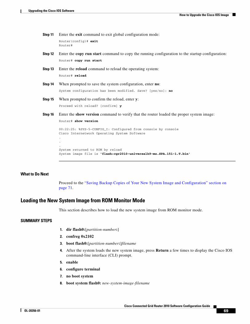
Upgrading the Cisco IOS SoftwareHow to Upgrade the Cisco IOS Image
Step 11 Enter the exit command to exit global configuration mode:
Router(config)# exit Router#
Step 12 Enter the copy run start command to copy the running configuration to the startup configuration:
Router# copy run start
Step 13 Enter the reload command to reload the operating system:
Router# reload
Step 14 When prompted to save the system configuration, enter no:
System configuration has been modified. Save? [yes/no]: no
Step 15 When prompted to confirm the reload, enter y:
Proceed with reload? [confirm] y
Step 16 Enter the show version command to verify that the router loaded the proper system image:
Router# show version
00:22:25: %SYS-5-CONFIG_I: Configured from console by consoleCisco Internetwork Operating System Software ...System returned to ROM by reloadSystem image file is "flash:cgr2010-universalk9-mz.SPA.151-1.T.bin"
What to Do Next
Proceed to the “Saving Backup Copies of Your New System Image and Configuration” section on page 71.
Loading the New System Image from ROM Monitor Mode
This section describes how to load the new system image from ROM monitor mode.
SUMMARY STEPS
1. dir flash0:[partition-number:]
2. confreg 0x2102
3. boot flash0:[partition-number:]filename
4. After the system loads the new system image, press Return a few times to display the Cisco IOS command-line interface (CLI) prompt.
5. enable
6. configure terminal
7. no boot system
8. boot system flash0: new-system-image-filename
69Cisco Connected Grid Router 2010 Software Configuration Guide
OL-20356-01

Upgrading the Cisco IOS SoftwareHow to Upgrade the Cisco IOS Image
9. (Optional) Repeat to specify the order in which the router should attempt to load any backup system images.
10. exit
11. copy run start
DETAILED STEPS
Step 1 Enter the dir flash0:[partition-number:] command to list files in flash memory:
rommon > dir flash0:program load complete, entry point: 0x80803000, size: 0x1b340Directory of flash0:
2 47089944 -rw- cgr2010-universalk9-mz.SPA.151-1.Trommon 3 >
Note whether the new system image is the first file or the only file listed in the dir flash0: command output. ( is not required if the image is the first file or only file listed.)
Step 2 Enter the confreg 0x2102 command to set the configuration register so that, after the next system reload or power cycle, the router loads a system image from the boot system commands in the startup configuration file:
rommon > confreg 0x2102
Step 3 Enter the boot flash0:[partition-number:]filename command to force the router to load the new system image:
rommon > boot flash0:cgr2010-universalk9-mz.SPA.151-1.T.bin
Step 4 After the system loads the new system image, press Return a few times to display the Cisco IOS CLI prompt.
Step 5 Enter the enable command to enable privileged EXEC mode, and enter your password if prompted:
Router> enable Password: <password> Router#
Step 6 Enter the configure terminal command to enter global configuration mode:
Router# configure terminalRouter(config)#
Step 7 Enter the no boot system to eliminate all entries in the bootable image list, which specifies the system image that the router loads at startup:
Router(config)# no boot system
Step 8 If the new system image is the first file or only the file displayed in the dir flash0: command output, this step is not required.
Enter the boot system flash new-system-image-filename command to load the new system image after the next system reload or power cycle:
Router(config)# boot system flash cgr2010-universalk9-mz.SPA.151-1.T.bin
Step 9 (Optional) Repeat to specify the order in which the router should attempt to load any backup system images.
70Cisco Connected Grid Router 2010 Software Configuration Guide
OL-20356-01
Upgrading the Cisco IOS SoftwareHow to Upgrade the Cisco IOS Image
Step 10 Enter the exit command to exit global configuration mode:
Router(config)# exit Router#
Step 11 Enter the copy run start command to copy the running configuration to the startup configuration:
Router# copy run start
What to Do Next
Proceed to the “Saving Backup Copies of Your New System Image and Configuration” section on page 71.
Saving Backup Copies of Your New System Image and ConfigurationTo aid file recovery and to minimize downtime in the event of file corruption, we recommend that you save backup copies of the startup configuration file and the Cisco IOS software system image file on a server.
Tip Do not erase any existing backup copies of your configuration and system image that you saved before upgrading your system image. If you encounter serious problems using your new system image or startup configuration, you can quickly revert to the previous working configuration and system image, if necessary.
For more detailed information, see the “Managing Configuration Files” chapter and the “Loading and Maintaining System Images” chapter of Cisco IOS Configuration Fundamentals Configuration Guide, Release 15.0.
To save backup copies of the startup configuration file and the system image file, complete the following steps:
SUMMARY STEPS
1. enable
2. copy nvram:startup-config {ftp: | rcp: | tftp:}
3. dir flash0:
4. copy flash0: {ftp: | rcp: | tftp:}
71Cisco Connected Grid Router 2010 Software Configuration Guide
OL-20356-01

Upgrading the Cisco IOS SoftwareHow to Upgrade the Cisco IOS Image
DETAILED STEPS
Examples
Copying the Startup Configuration to a TFTP Server: Example
The following example shows the startup configuration being copied to a TFTP server:
Router# copy nvram:startup-config tftp:
Remote host[]? 172.16.101.101
Name of configuration file to write [rtr2-confg]? <cr> Write file rtr2-confg on host 172.16.101.101?[confirm] <cr> ![OK]
Copying from Flash Memory to a TFTP Server: Example
The following example uses the dir flash: privileged EXEC command to obtain the name of the system image file and the copy flash: tftp: privileged EXEC command to copy the system image to a TFTP server. The router uses the default username and password.
Router# dir flash0:
System flash directory:File Length Name/status1 4137888 cgr2010-mz[4137952 bytes used, 12639264 available, 16777216 total]16384K bytes of processor board System flash (Read/Write)\
Router# copy flash0: tftp: IP address of remote host [255.255.255.255]? 192.0.0.1 filename to write on tftp host? cgr2010-mz
Command or Action Purpose
Step 1 enable
Example:Router> enable
Enables privileged EXEC mode.
• Enter your password if prompted.
Step 2 copy nvram:startup-config {ftp: | rcp: | tftp:}
Example:Router# copy nvram:startup-config ftp:
Copies the startup configuration file to a server.
• The configuration file copy serves as a backup copy.
• Enter the destination URL when prompted.
Step 3 dir flash0:
Example:Router# dir flash0:
Displays the layout and contents of a flash memory file system.
• Write down the name of the system image file.
Step 4 copy flash0: {ftp: | rcp: | tftp:}
Example:Router# copy flash0: ftp:
Copies a file from flash memory to a server.
• Copy the system image file to a server to serve as a backup copy.
• Enter the flash memory partition number if prompted.
• Enter the filename and destination URL when prompted.
72Cisco Connected Grid Router 2010 Software Configuration Guide
OL-20356-01
Upgrading the Cisco IOS SoftwareAdditional References
writing cgr2010-mz !!!!...successful ftp write.
Additional ReferencesThe following sections provide references related to upgrading the system image on your router.
Related Documents and Websites
Technical Assistance
Related Topic Document Title or Website
Matching Cisco IOS releases and features to hardware Cisco Feature Navigator
Choosing and downloading system images Cisco Download Software website
Loading and maintaining system images Cisco IOS and NX-OS Software, Loading and Managing System Images
Removing, inserting, and upgrading compact flash memory cards
Hardware Installation Guide for your router
Connecting your PC to the router console port Hardware Installation Guide for your router
Description Link
Technical Assistance Center (TAC) home page, containing 30,000 pages of searchable technical content, including links to products, technologies, solutions, technical tips, and tools. Registered Cisco.com users can log in from this page to access even more content.1
1. You must have an account on Cisco.com. If you do not have an account or have forgotten your username or password, click Cancel at the login dialog box and follow the instructions that appear.
http://www.cisco.com/public/support/tac/home.shtml
73Cisco Connected Grid Router 2010 Software Configuration Guide
OL-20356-01

Upgrading the Cisco IOS SoftwareAdditional References
74Cisco Connected Grid Router 2010 Software Configuration Guide
OL-20356-01

Using CompactFlash Memory
First Published: May 27, 2010, OL-20356-01Last Updated: October 25, 2017
The Cisco Connected Grid Router 2010 uses Advanced Capability CF external memory to store the system image, configuration files, and some software data files. CF supports true integrated development environment mode and multi-word direct memory access mode.
This document explains how to manage directories and files on the CF in the following sections:
• Requirements and Restrictions, page 75
• Online Insertion and Removal, page 76
• Formatting CompactFlash Memory as a Class C File System, page 76
• File Operations on CompactFlash Memory Cards, page 77
• Directory Operations on a CompactFlash Memory Card, page 81
Requirements and RestrictionsCompactFlash Support
• Only Advanced Capability CF purchased from Cisco operate in the Cisco CGR 2010 router.
• Legacy CF will not operate in Cisco CGR 2010 router. When legacy CF is inserted, the following error message appears:
WARNING: Unsupported compact flash detected. Use of this card during normal operation can impact and severely degrade performance of the system. Please use supported compact flash cards only.
Formatting CompactFlash
• Only Class C file systems are supported on Cisco PCMCIA CompactFlash (CF).
• We recommend that you format new CF to initialize a new flash file system. Proper formatting lets the ROM monitor recognize and boot the flash memory. The CF can be formatted on a router, and files can be copied to or from any PC that is equipped with a CF memory reader. If you use a PC to format the CF, use the Microsoft File Allocation Table (FAT32) file system.
Americas Headquarters:Cisco Systems, Inc., 170 West Tasman Drive, San Jose, CA 95134-1706 USA
© 2010 Cisco Systems, Inc. All rights reserved.
Using CompactFlash MemoryOnline Insertion and Removal
CompactFlash Slots and Files
• Cisco CGR 2010 routers have two types of external CF slots
– 2— PCMCIA
– 2— USB
• CF in slot0 can store the system image, configuration, and data files. The CF must be present in this slot for the router to boot and perform normal file operations.
Note Use flash1 in the command syntax to access CF in slot 1. Use flash0 in the command syntax to access CF in slot 0.
Table 1 Compact Flash Slot Numbering and Naming
Online Insertion and RemovalOnline insertion and removal (OIR) is a feature that allows you to replace CompactFlash memory cards without turning off the router and without affecting the operation of other interfaces. OIR of CF memory cards provides uninterrupted operation to network users, maintains routing information, and ensures session preservation.
Caution The external CF memory card should not be removed if the flash memory busy “CF” LED on the router is blinking, because this indicates that the software is accessing the CF memory card. Removing the CF memory card may disrupt the network, because some software features use the CF memory card to store tables and other important data.
For instructions on inserting, removing, and replacing the external CF memory card, see the router’s Hardware Installation Guide.
Formatting CompactFlash Memory as a Class C File SystemUse the format flash: command in privileged EXEC mode to:
• Format CF memory cards with a Class C flash file system
• Remove the files from a CF memory card previously formatted with a Class C flash file system
Note Use flash1 in the command syntax to access CF in slot 1. Use flash0 in the command syntax to access CF in slot 0.
Formatting CompactFlash Memory as a Class C Flash File System: Example
Slot Number PCMCIA CF Filenames USB CF Filenames Size
Slot01 flash0 usbflash0 256MB
Slot1 flash1 usbflash1 0
Total - - 4GB
1. Slot 0 is the default CF slot. CF in slot0 can store system image, configuration, and data files. CF must be present in this slot for the router to boot and perform normal file operations.
76Cisco Connected Grid Router 2010 Software Configuration Guide
OL-20356-01
Using CompactFlash MemoryFile Operations on CompactFlash Memory Cards
Router# format flash:Format operation may take a while. Continue? [confirm]Format operation will destroy all data in "flash:". Continue? [confirm]Enter volume ID (up to 64 chars)[default flash]:Current Low End File System flash card in flash will be formatted into DOSFile System flash card! Continue? [confirm]Format:Drive communication & 1st Sector Write OK...Writing Monlib sectors ..................................................................Monlib write completeFormat:All system sectors written. OK...Format:Total sectors in formatted partition:250592Format:Total bytes in formatted partition:128303104Format:Operation completed successfully.Format of flash complete
File Operations on CompactFlash Memory CardsThis section describes the following file operations for external CF memory cards:
• Copying Files, page 77
• Displaying Files, page 78
• Displaying File Content, page 78
• Displaying Geometry and Format Information, page 79
• Deleting Files, page 80
• Renaming Files, page 80
Copying FilesTo copy files, enter the copy command in privileged EXEC mode. To indicate a file that is stored in a CF memory card, precede the filename with flash.
Note Use flash1 in the command syntax to access CF in slot 1. Use flash0 in the command syntax to access CF in slot 0.
Examples: Copying Files
In the following example, the file my-config1 on the CF memory card is copied into the startup-config file in the system memory:
Router# copy flash:my-config1 startup-config
Destination filename [startup-config]?[OK]517 bytes copied in 4.188 secs (129 bytes/sec)
In the following example, the file my-config2 on the CF memory card is copied into the running-config file in the system memory:
Router# copy flash:my-config2 running-config
Destination filename [running-config]?709 bytes copied in 0.72 secs
77Cisco Connected Grid Router 2010 Software Configuration Guide
OL-20356-01
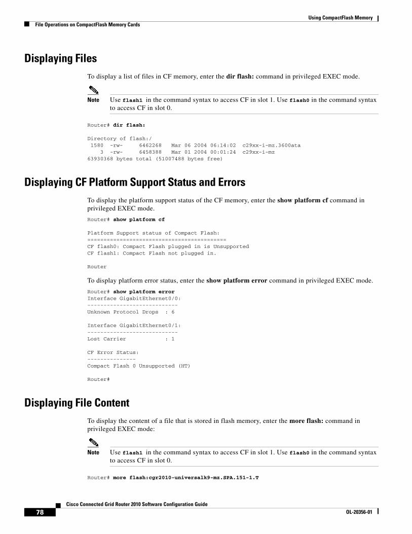
Using CompactFlash MemoryFile Operations on CompactFlash Memory Cards
Displaying FilesTo display a list of files in CF memory, enter the dir flash: command in privileged EXEC mode.
Note Use flash1 in the command syntax to access CF in slot 1. Use flash0 in the command syntax to access CF in slot 0.
Router# dir flash:
Directory of flash:/ 1580 -rw- 6462268 Mar 06 2004 06:14:02 c29xx-i-mz.3600ata 3 -rw- 6458388 Mar 01 2004 00:01:24 c29xx-i-mz63930368 bytes total (51007488 bytes free)
Displaying CF Platform Support Status and ErrorsTo display the platform support status of the CF memory, enter the show platform cf command in privileged EXEC mode.
Router# show platform cf
Platform Support status of Compact Flash:===========================================CF flash0: Compact Flash plugged in is UnsupportedCF flash1: Compact Flash not plugged in.
Router
To display platform error status, enter the show platform error command in privileged EXEC mode.
Router# show platform errorInterface GigabitEthernet0/0:----------------------------Unknown Protocol Drops : 6
Interface GigabitEthernet0/1:----------------------------Lost Carrier : 1
CF Error Status:---------------Compact Flash 0 Unsupported (HT)
Router#
Displaying File ContentTo display the content of a file that is stored in flash memory, enter the more flash: command in privileged EXEC mode:
Note Use flash1 in the command syntax to access CF in slot 1. Use flash0 in the command syntax to access CF in slot 0.
Router# more flash:cgr2010-universalk9-mz.SPA.151-1.T
78Cisco Connected Grid Router 2010 Software Configuration Guide
OL-20356-01
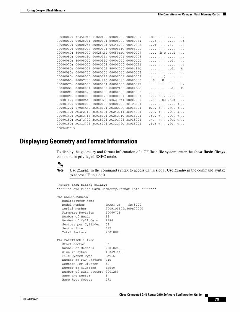
Using CompactFlash MemoryFile Operations on CompactFlash Memory Cards
00000000: 7F454C46 01020100 00000000 00000000 .ELF .... .... ....00000010: 00020061 00000001 80008000 00000034 ...a .... .... ...400000020: 00000054 20000001 00340020 00010028 ...T ... .4. ...(00000030: 00050008 00000001 0000011C 80008000 .... .... .... ....00000040: 80008000 00628A44 00650EEC 00000007 .... .b.D .e.l ....00000050: 0000011C 0000001B 00000001 00000006 .... .... .... ....00000060: 80008000 0000011C 00004000 00000000 .... .... ..@. ....00000070: 00000000 00000008 00000000 00000021 .... .... .... ...!00000080: 00000001 00000002 8000C000 0000411C .... .... ..@. ..A.00000090: 00000700 00000000 00000000 00000004 .... .... .... ....000000A0: 00000000 00000029 00000001 00000003 .... ...) .... ....000000B0: 8000C700 0000481C 00000380 00000000 ..G. ..H. .... ....000000C0: 00000000 00000004 00000000 0000002F .... .... .... .../000000D0: 00000001 10000003 8000CA80 00004B9C .... .... ..J. ..K.000000E0: 00000020 00000000 00000000 00000008 ... .... .... ....000000F0: 00000000 0000002F 00000001 10000003 .... .../ .... ....00000100: 8000CAA0 00004BBC 00623FA4 00000000 ..J ..K< .b?$ ....00000110: 00000000 00000008 00000000 3C1C8001 .... .... .... <...00000120: 679C4A80 3C018001 AC3DC70C 3C018001 g.J. <... ,=G. <...00000130: AC3FC710 3C018001 AC24C714 3C018001 ,?G. <... ,$G. <...00000140: AC25C718 3C018001 AC26C71C 3C018001 ,%G. <... ,&G. <...00000150: AC27C720 3C018001 AC30C724 3C018001 ,'G <... ,0G$ <...00000160: AC31C728 3C018001 AC32C72C 3C018001 ,1G( <... ,2G, <...--More-- q
Displaying Geometry and Format InformationTo display the geometry and format information of a CF flash file system, enter the show flash: filesys command in privileged EXEC mode.
Note Use flash1 in the command syntax to access CF in slot 1. Use flash0 in the command syntax to access CF in slot 0.
Router# show flash0 filesys ******** ATA Flash Card Geometry/Format Info ********
ATA CARD GEOMETRY Manufacturer Name Model Number SMART CF fs:8000 Serial Number 2009101509D809B20000 Firmware Revision 20060729 Number of Heads 16 Number of Cylinders 1986 Sectors per Cylinder 63 Sector Size 512 Total Sectors 2001888
ATA PARTITION 1 INFO Start Sector 63 Number of Sectors 2001825 Size in Bytes 1024934400 File System Type FAT16 Number of FAT Sectors 245 Sectors Per Cluster 32 Number of Clusters 62540 Number of Data Sectors 2001280 Base FAT Sector 1 Base Root Sector 491
79Cisco Connected Grid Router 2010 Software Configuration Guide
OL-20356-01
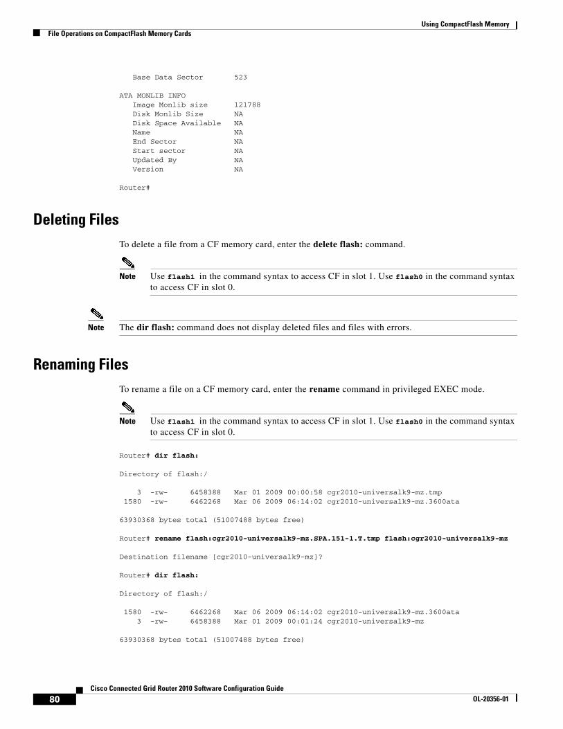
Using CompactFlash MemoryFile Operations on CompactFlash Memory Cards
Base Data Sector 523
ATA MONLIB INFO Image Monlib size 121788 Disk Monlib Size NA Disk Space Available NA Name NA End Sector NA Start sector NA Updated By NA Version NA
Router#
Deleting FilesTo delete a file from a CF memory card, enter the delete flash: command.
Note Use flash1 in the command syntax to access CF in slot 1. Use flash0 in the command syntax to access CF in slot 0.
Note The dir flash: command does not display deleted files and files with errors.
Renaming FilesTo rename a file on a CF memory card, enter the rename command in privileged EXEC mode.
Note Use flash1 in the command syntax to access CF in slot 1. Use flash0 in the command syntax to access CF in slot 0.
Router# dir flash:
Directory of flash:/
3 -rw- 6458388 Mar 01 2009 00:00:58 cgr2010-universalk9-mz.tmp 1580 -rw- 6462268 Mar 06 2009 06:14:02 cgr2010-universalk9-mz.3600ata
63930368 bytes total (51007488 bytes free)
Router# rename flash:cgr2010-universalk9-mz.SPA.151-1.T.tmp flash:cgr2010-universalk9-mz
Destination filename [cgr2010-universalk9-mz]?
Router# dir flash:
Directory of flash:/
1580 -rw- 6462268 Mar 06 2009 06:14:02 cgr2010-universalk9-mz.3600ata 3 -rw- 6458388 Mar 01 2009 00:01:24 cgr2010-universalk9-mz
63930368 bytes total (51007488 bytes free)
80Cisco Connected Grid Router 2010 Software Configuration Guide
OL-20356-01

Using CompactFlash MemoryDirectory Operations on a CompactFlash Memory Card
Directory Operations on a CompactFlash Memory CardThe following sections describe directory operations for external CF memory cards on Cisco routers:
• Entering a Directory and Determining Which Directory You Are In, page 81
• Creating a New Directory, page 81
• Removing a Directory, page 82
Entering a Directory and Determining Which Directory You Are InTo enter a directory of a CF memory card, enter the cd command in privileged EXEC mode. The cd command specifies or changes the default directory or file system. If you enter cd only, without specifying a file system, the router enters the default home directory, which is flash0. If you enter cd flash1 or cd usbflash1, the router enters the flash1 directory.
Router# cd
To determine which directory you are in, enter the pwd command in privileged EXEC mode. The CLI displays which directory or file system is specified as the default by the cd command.
Router# pwd
To display a list of files in the directory that you are in, enter the dir command in privileged EXEC mode. The command-line interface will display the files in the file system that was specified as the default by the cd command.
Router# dir flash:
Directory of flash:/
1580 -rw- 6462268 Mar 06 2009 06:14:02 cgr2010-universalk9-mz.3600ata 3 -rw- 6458388 Mar 01 2009 00:01:24 cgr2010-universalk9-mz
63930368 bytes total (51007488 bytes free)
Entering a Directory: Example
To enter the /config directory:
Router# cd config
To verify that you are in the /config directory:Router# pwd
flash:/config/
Router# dir
Directory of flash:/config/
380 -rw- 6462268 Mar 08 2004 06:14:02 myconfig1 203 -rw- 6458388 Mar 03 2004 00:01:24 myconfig2
63930368 bytes total (51007488 bytes free)
Creating a New DirectoryTo create a directory in flash memory, enter the mkdir flash: command in privileged EXEC mode.
81Cisco Connected Grid Router 2010 Software Configuration Guide
OL-20356-01

Using CompactFlash MemoryDirectory Operations on a CompactFlash Memory Card
Note Use flash1 in the command syntax to access CF in slot 1. Use flash0 in the command syntax to access CF in slot 0.
Creating a New Directory: Example
In the following example, a new directory named “config” is created; then a new subdirectory named “test-config” is created within the “config” directory.
Router# dir flash:
Directory of flash:/
1580 -rw- 6462268 Mar 06 2009 06:14:02 cgr2010-universalk9-mz.3600ata 3 -rw- 6458388 Mar 01 2009 00:01:24 cgr2010-universalk9-mz
63930368 bytes total (51007488 bytes free)
Router# mkdir flash:/config
Create directory filename [config]?Created dir flash:/config
Router# mkdir flash:/config/test-config
Create directory filename [/config/test-config]?Created dir flash:/config/test-config
Router# dir flash:
Directory of flash:/
3 -rw- 6458388 Mar 01 2009 00:01:24 cgr2010-universalk9-mz1580 drw- 0 Mar 01 2004 23:48:36 config
63930368 bytes total (51007488 bytes free)
Removing a DirectoryTo remove a directory in flash memory, enter the rmdir flash: command in privileged EXEC mode.
Before you can remove a directory, you must remove all files and subdirectories from the directory.
Note Use flash1 in the command syntax to access CF in slot 1. Use flash0 in the command syntax to access CF in slot 0.
Example: Removing a Directory
In the following example, the subdirectory test-config is removed.
Router# dir
Directory of flash:/config/
1581 drw- 0 Mar 01 2004 23:50:08 test-config
128094208 bytes total (121626624 bytes free)
82Cisco Connected Grid Router 2010 Software Configuration Guide
OL-20356-01

Using CompactFlash MemoryDirectory Operations on a CompactFlash Memory Card
Router# rmdir flash:/config/test-config
Remove directory filename [/config/test-config]?Delete flash:/config/test-config? [confirm]Removed dir flash:/config/test-configRouter# dir
Directory of flash:/config/
No files in directory
128094208 bytes total (121630720 bytes free)
83Cisco Connected Grid Router 2010 Software Configuration Guide
OL-20356-01

Using CompactFlash MemoryDirectory Operations on a CompactFlash Memory Card
84Cisco Connected Grid Router 2010 Software Configuration Guide
OL-20356-01
Using ROM Monitor
First Published: May 27, 2010, OL-20356-01Last Updated: October 25, 2017
Many users do not use the ROM monitor at all, unless during power up or reload, the router does not find a valid system image, the last digit of the boot field in the configuration register is 0, or you enter the Break key sequence of the terminal that is plugged into the router console port during the first 60 seconds after reloading the router.
This document describes how to use the ROM monitor to manually load a system image, upgrade the system image when there are no TFTP servers or network connections, or for disaster recovery.
Contents• Platforms Supported by This Document, page 85
• Prerequisites for Using the ROM Monitor, page 85
• Information About the ROM Monitor, page 86
• How to Use the ROM Monitor—Typical Tasks, page 87
• Additional References, page 114
Platforms Supported by This DocumentThis document describes use of the ROM monitor with the Cisco Connected Grid Router 2010.
Prerequisites for Using the ROM MonitorConnect a terminal or PC to the router console port. For help, see the hardware installation guide for your router.
Americas Headquarters:Cisco Systems, Inc., 170 West Tasman Drive, San Jose, CA 95134-1706 USA
© 2010 Cisco Systems, Inc. All rights reserved.
Using ROM MonitorInformation About the ROM Monitor
Information About the ROM MonitorBefore using the ROM monitor, you should understand the following concepts:
• ROM Monitor Mode Command Prompt, page 86
• Why is the Router in ROM Monitor Mode?, page 86
• When do I use ROM Monitor?, page 86
• Tips for Using ROM Monitor Commands, page 87
• Accessibility, page 87
ROM Monitor Mode Command PromptThe ROM monitor uses the rommon x > command prompt. The x variable begins at one and increments each time you press Return or Enter in ROM monitor mode.
Why is the Router in ROM Monitor Mode?The router boots to ROM monitor mode when one of the following occurs:
• During power up or reload, the router did not find a valid system image.
• The last digit of the boot field in the configuration register is 0 (for example, 0x100 or 0x0).
• You enter the Break key sequence (typically, Ctrl-Break) of the terminal that is plugged into the router console port during the first 60 seconds after reloading the router.
To exit ROM monitor mode, see the “Exiting ROM Monitor Mode” section on page 112.
When do I use ROM Monitor?Use ROM monitor when:
• Manually loading a system image—You can load a system image without configuring the router to load that image in future system reloads or power-cycles. This can be useful for testing a new system image or for troubleshooting. See the “Loading a System Image (boot)” section on page 93.
• Upgrading the system image when there are no TFTP servers or network connections, and a direct PC connection to the router console is the only viable option—See information about upgrading the system image in the configuration documentation for your router.
• Troubleshooting if the router crashes and hangs—See the “Troubleshooting Crashes and Hangs (stack, context, frame, sysret, meminfo)” section on page 107.
• Recovering from a system disaster—Use one of the following methods for recovering the system image or configuration file:
Note Recovering the system image is different from upgrading the system image. You need to recover the system image if it becomes corrupt or if it is deleted because of a disaster that affects the memory device severely enough to require deleting all data on the memory device to load a system image.
86Cisco Connected Grid Router 2010 Software Configuration Guide
OL-20356-01
Using ROM MonitorHow to Use the ROM Monitor—Typical Tasks
– TFTP download (tftpdnld)—Use this method if you can connect a TFTP server directly to the fixed LAN port on your router. See the “Downloading the System Image (tftpdnld)” section on page 103.
Tips for Using ROM Monitor Commands• ROM monitor commands are case sensitive.
• You can halt any ROM monitor command by entering the Break key sequence (Ctrl-Break) on the PC or terminal. The Break key sequence varies, depending on the software on your PC or terminal. If Ctrl-Break does not work, see the Standard Break Key Sequence Combinations During Password Recovery troubleshooting tech note.
• To find out which commands are available on your router and to display command syntax options, see the “Displaying Commands and Command Syntax in ROM Monitor Mode (?, help, -?)” section on page 92.
AccessibilityThe Cisco Connected Grid Router 2010 can be configured using the Cisco command-line interface (CLI). The CLI conforms to accessibility code 508 because it is text based and it relies on a keyboard for navigation. All functions of the router can be configured and monitored using the CLI.
For a complete list of guidelines and Cisco products adherence to accessibility, see Cisco Accessibility Products.
How to Use the ROM Monitor—Typical TasksThis section provides the following procedures:
• Entering ROM Monitor Mode, page 88
• Displaying Commands and Command Syntax in ROM Monitor Mode (?, help, -?), page 92
• Displaying Files in a File System (dir), page 93
• Loading a System Image (boot), page 93
• Modifying the Configuration Register, page 98
• Obtaining Information on USB Flash Devices, page 99
• Modifying the I/O Memory (iomemset), page 100
• Upgrading of ROM Monitor command Using Cisco IOS, page 102
• Downloading the System Image (tftpdnld), page 103
• Troubleshooting Crashes and Hangs (stack, context, frame, sysret, meminfo), page 107
• Exiting ROM Monitor Mode, page 112
Note This section does not describe how to perform all possible ROM monitor tasks. Use the command help to list and perform any tasks that are not described in this document. See the “Displaying Commands and Command Syntax in ROM Monitor Mode (?, help, -?)” section on page 92.
87Cisco Connected Grid Router 2010 Software Configuration Guide
OL-20356-01
Using ROM MonitorHow to Use the ROM Monitor—Typical Tasks
Entering ROM Monitor ModeThis section provides two ways to enter ROM monitor mode:
• Using the Break Key Sequence to Interrupt the System Reload and Enter ROM Monitor Mode, page 88
• Setting the Configuration Register to Boot to ROM Monitor Mode, page 90
Prerequisites
Connect a terminal or PC to the router console port. For help, see the hardware installation guide for your router.
Using the Break Key Sequence to Interrupt the System Reload and Enter ROM Monitor Mode
This section describes how to enter ROM monitor mode by reloading the router and entering the Break key sequence.
Note Bit 8 controls the console Break key (see Table 1 on page 116):
• Setting bit 8 (Factory default) causes the processor to ignore the console Break key.
• Clearing bit 8 causes the processor to interpret Break as a command to force the router into the ROM monitor mode, halting normal operation.
Break can always be sent in the first 60 seconds while the router is rebooting, regardless of the configuration register settings.
SUMMARY STEPS
1. enable
2. reload
3. Press Ctrl-Break.
88Cisco Connected Grid Router 2010 Software Configuration Guide
OL-20356-01
Using ROM MonitorHow to Use the ROM Monitor—Typical Tasks
DETAILED STEPS
Examples
This section provides an example of the reload command:
Sample Output for the reload CommandUse break key sequence to enter rom monitorRouter# reload
Proceed with reload? [confirm] *Sep 23 15:54:25.871: %SYS-5-RELOAD: Reload requested by console. Reload Reason: Reload command.
Note Clearing bit 8 causes the processor to interpret Break as a command to force the router into the ROM monitor mode, halting normal operation.
telnet> send break *** System received an abort due to Break Key ***signal= 0x3, code= 0x0, context= 0x431aaf40PC = 0x4008b5dc, Cause = 0x20, Status Reg = 0x3400c102
Troubleshooting Tips
The Break key sequence varies, depending on the software on your PC or terminal. See Standard Break Key Sequence Combinations During Password Recovery.
What to Do Next
• Proceed to the “Displaying Commands and Command Syntax in ROM Monitor Mode (?, help, -?)” section on page 92.
Command or Action Purpose
Step 1 enable
Example:Router> enable
Enables privileged EXEC mode.
• Enter your password if prompted.
Step 2 reload
Example:Router# reload
Reloads the operating system.
Step 3 Immediately press Ctrl-Break.
Example:Router# send break
Interrupts the router reload and enters ROM monitor mode.
• You must perform this step within 60 seconds after you enter the reload command.
• The Break key sequence varies, depending on the software on your PC or terminal. If Ctrl-Break does not work, see Standard Break Key Sequence Combinations During Password Recovery.
89Cisco Connected Grid Router 2010 Software Configuration Guide
OL-20356-01
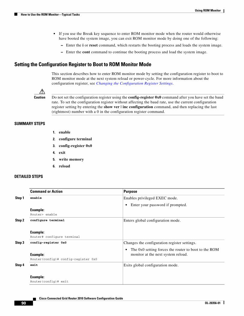
Using ROM MonitorHow to Use the ROM Monitor—Typical Tasks
• If you use the Break key sequence to enter ROM monitor mode when the router would otherwise have booted the system image, you can exit ROM monitor mode by doing one of the following:
– Enter the i or reset command, which restarts the booting process and loads the system image.
– Enter the cont command to continue the booting process and load the system image.
Setting the Configuration Register to Boot to ROM Monitor Mode
This section describes how to enter ROM monitor mode by setting the configuration register to boot to ROM monitor mode at the next system reload or power-cycle. For more information about the configuration register, see Changing the Configuration Register Settings.
Caution Do not set the configuration register using the config-register 0x0 command after you have set the baud rate. To set the configuration register without affecting the baud rate, use the current configuration register setting by entering the show ver | inc configuration command, and then replacing the last (rightmost) number with a 0 in the configuration register command.
SUMMARY STEPS
1. enable
2. configure terminal
3. config-register 0x0
4. exit
5. write memory
6. reload
DETAILED STEPS
Command or Action Purpose
Step 1 enable
Example:Router> enable
Enables privileged EXEC mode.
• Enter your password if prompted.
Step 2 configure terminal
Example:Router# configure terminal
Enters global configuration mode.
Step 3 config-register 0x0
Example:Router(config)# config-register 0x0
Changes the configuration register settings.
• The 0x0 setting forces the router to boot to the ROM monitor at the next system reload.
Step 4 exit
Example:Router(config)# exit
Exits global configuration mode.
90Cisco Connected Grid Router 2010 Software Configuration Guide
OL-20356-01
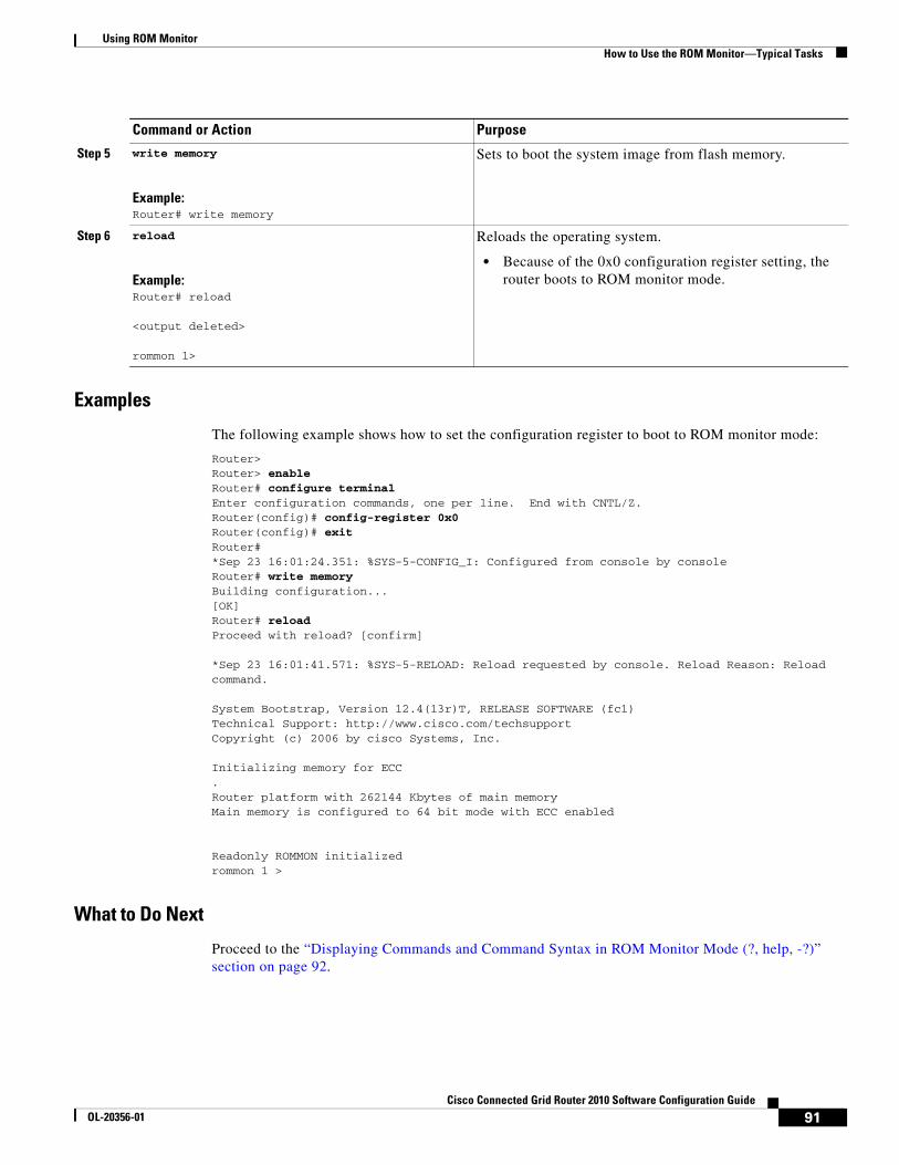
Using ROM MonitorHow to Use the ROM Monitor—Typical Tasks
Examples
The following example shows how to set the configuration register to boot to ROM monitor mode:
Router>Router> enableRouter# configure terminalEnter configuration commands, one per line. End with CNTL/Z.Router(config)# config-register 0x0Router(config)# exitRouter#*Sep 23 16:01:24.351: %SYS-5-CONFIG_I: Configured from console by consoleRouter# write memoryBuilding configuration...[OK]Router# reloadProceed with reload? [confirm] *Sep 23 16:01:41.571: %SYS-5-RELOAD: Reload requested by console. Reload Reason: Reload command. System Bootstrap, Version 12.4(13r)T, RELEASE SOFTWARE (fc1)Technical Support: http://www.cisco.com/techsupportCopyright (c) 2006 by cisco Systems, Inc. Initializing memory for ECC.Router platform with 262144 Kbytes of main memoryMain memory is configured to 64 bit mode with ECC enabled
Readonly ROMMON initializedrommon 1 >
What to Do Next
Proceed to the “Displaying Commands and Command Syntax in ROM Monitor Mode (?, help, -?)” section on page 92.
Step 5 write memory
Example:Router# write memory
Sets to boot the system image from flash memory.
Step 6 reload
Example:Router# reload
<output deleted>
rommon 1>
Reloads the operating system.
• Because of the 0x0 configuration register setting, the router boots to ROM monitor mode.
Command or Action Purpose
91Cisco Connected Grid Router 2010 Software Configuration Guide
OL-20356-01
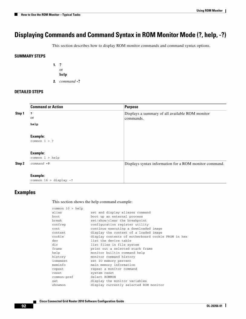
Using ROM MonitorHow to Use the ROM Monitor—Typical Tasks
Displaying Commands and Command Syntax in ROM Monitor Mode (?, help, -?)This section describes how to display ROM monitor commands and command syntax options.
SUMMARY STEPS
1. ? or help
2. command -?
DETAILED STEPS
Examples
This section shows the help command example:
rommon 10 > helpalias set and display aliases commandboot boot up an external processbreak set/show/clear the breakpointconfreg configuration register utilitycont continue executing a downloaded imagecontext display the context of a loaded imagecookie display contents of motherboard cookie PROM in hexdev list the device tabledir list files in file systemframe print out a selected stack framehelp monitor builtin command helphistory monitor command historyiomemset set IO memory percentmeminfo main memory informationrepeat repeat a monitor commandreset system resetrommon-pref Select ROMMONset display the monitor variablesshowmon display currently selected ROM monitor
Command or Action Purpose
Step 1 ?
or
help
Example:rommon 1 > ?
Example:rommon 1 > help
Displays a summary of all available ROM monitor commands.
Step 2 command -?
Example:rommon 16 > display -?
Displays syntax information for a ROM monitor command.
92Cisco Connected Grid Router 2010 Software Configuration Guide
OL-20356-01
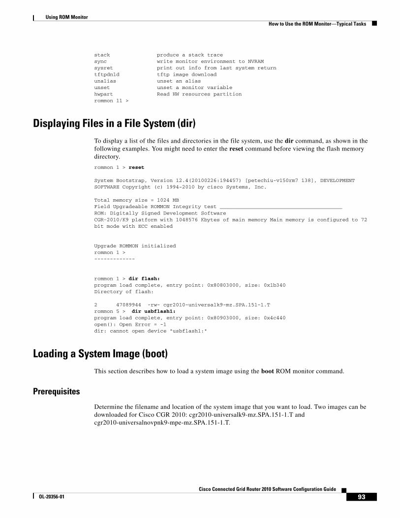
Using ROM MonitorHow to Use the ROM Monitor—Typical Tasks
stack produce a stack tracesync write monitor environment to NVRAMsysret print out info from last system returntftpdnld tftp image downloadunalias unset an aliasunset unset a monitor variablehwpart Read HW resources partitionrommon 11 >
Displaying Files in a File System (dir)To display a list of the files and directories in the file system, use the dir command, as shown in the following examples. You might need to enter the reset command before viewing the flash memory directory.
rommon 1 > reset
System Bootstrap, Version 12.4(20100226:194457) [petechiu-v150rm7 138], DEVELOPMENT SOFTWARE Copyright (c) 1994-2010 by cisco Systems, Inc.
Total memory size = 1024 MBField Upgradeable ROMMON Integrity test _______________________________________ROM: Digitally Signed Development SoftwareCGR-2010/K9 platform with 1048576 Kbytes of main memory Main memory is configured to 72 bit mode with ECC enabled
Upgrade ROMMON initializedrommon 1 >-------------
rommon 1 > dir flash:program load complete, entry point: 0x80803000, size: 0x1b340Directory of flash:
2 47089944 -rw- cgr2010-universalk9-mz.SPA.151-1.Trommon 5 > dir usbflash1:program load complete, entry point: 0x80903000, size: 0x4c440open(): Open Error = -1dir: cannot open device "usbflash1:"
Loading a System Image (boot)This section describes how to load a system image using the boot ROM monitor command.
Prerequisites
Determine the filename and location of the system image that you want to load. Two images can be downloaded for Cisco CGR 2010: cgr2010-universalk9-mz.SPA.151-1.T and cgr2010-universalnovpnk9-mpe-mz.SPA.151-1.T.
93Cisco Connected Grid Router 2010 Software Configuration Guide
OL-20356-01
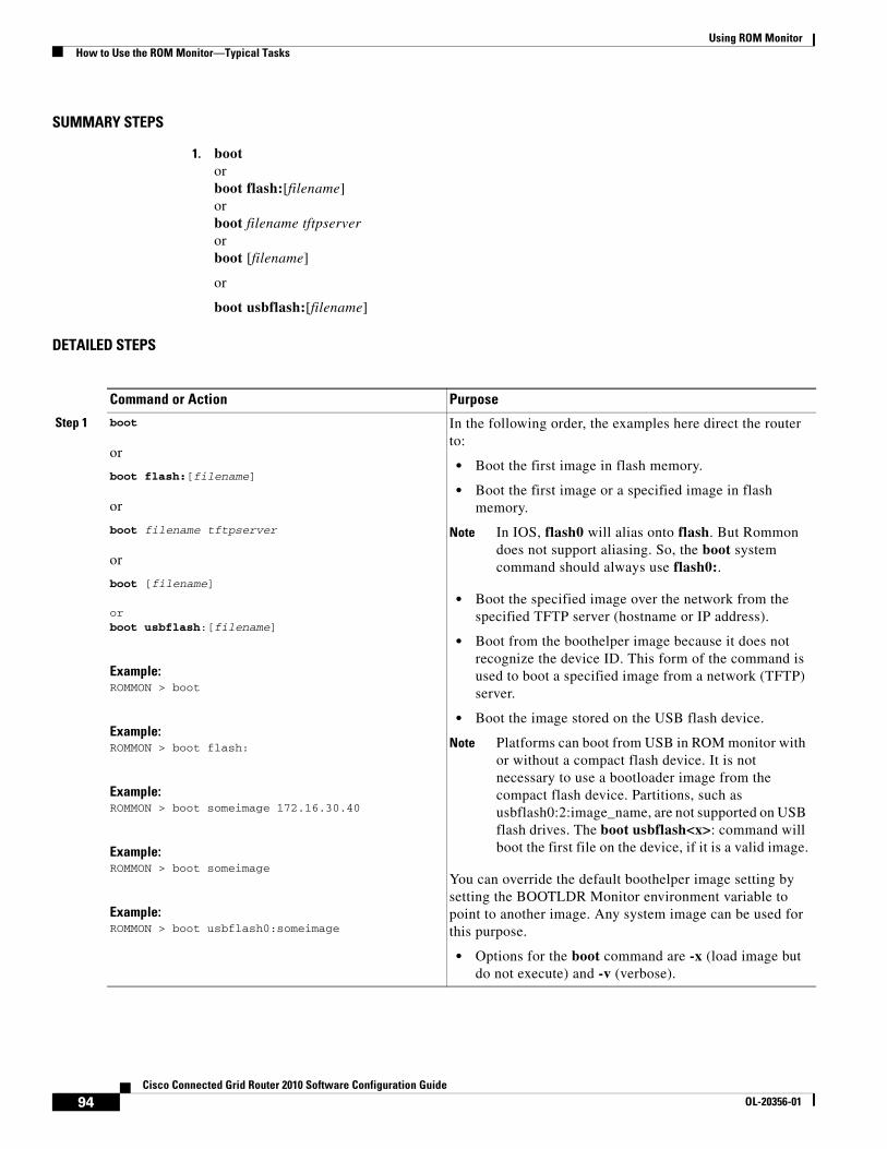
Using ROM MonitorHow to Use the ROM Monitor—Typical Tasks
SUMMARY STEPS
1. boot orboot flash:[filename] orboot filename tftpserver orboot [filename]
or
boot usbflash:[filename]
DETAILED STEPS
Command or Action Purpose
Step 1 boot
or
boot flash:[filename]
or
boot filename tftpserver
or
boot [filename]
orboot usbflash:[filename]
Example:ROMMON > boot
Example:ROMMON > boot flash:
Example:ROMMON > boot someimage 172.16.30.40
Example:ROMMON > boot someimage
Example:ROMMON > boot usbflash0:someimage
In the following order, the examples here direct the router to:
• Boot the first image in flash memory.
• Boot the first image or a specified image in flash memory.
Note In IOS, flash0 will alias onto flash. But Rommon does not support aliasing. So, the boot system command should always use flash0:.
• Boot the specified image over the network from the specified TFTP server (hostname or IP address).
• Boot from the boothelper image because it does not recognize the device ID. This form of the command is used to boot a specified image from a network (TFTP) server.
• Boot the image stored on the USB flash device.
Note Platforms can boot from USB in ROM monitor with or without a compact flash device. It is not necessary to use a bootloader image from the compact flash device. Partitions, such as usbflash0:2:image_name, are not supported on USB flash drives. The boot usbflash<x>: command will boot the first file on the device, if it is a valid image.
You can override the default boothelper image setting by setting the BOOTLDR Monitor environment variable to point to another image. Any system image can be used for this purpose.
• Options for the boot command are -x (load image but do not execute) and -v (verbose).
94Cisco Connected Grid Router 2010 Software Configuration Guide
OL-20356-01
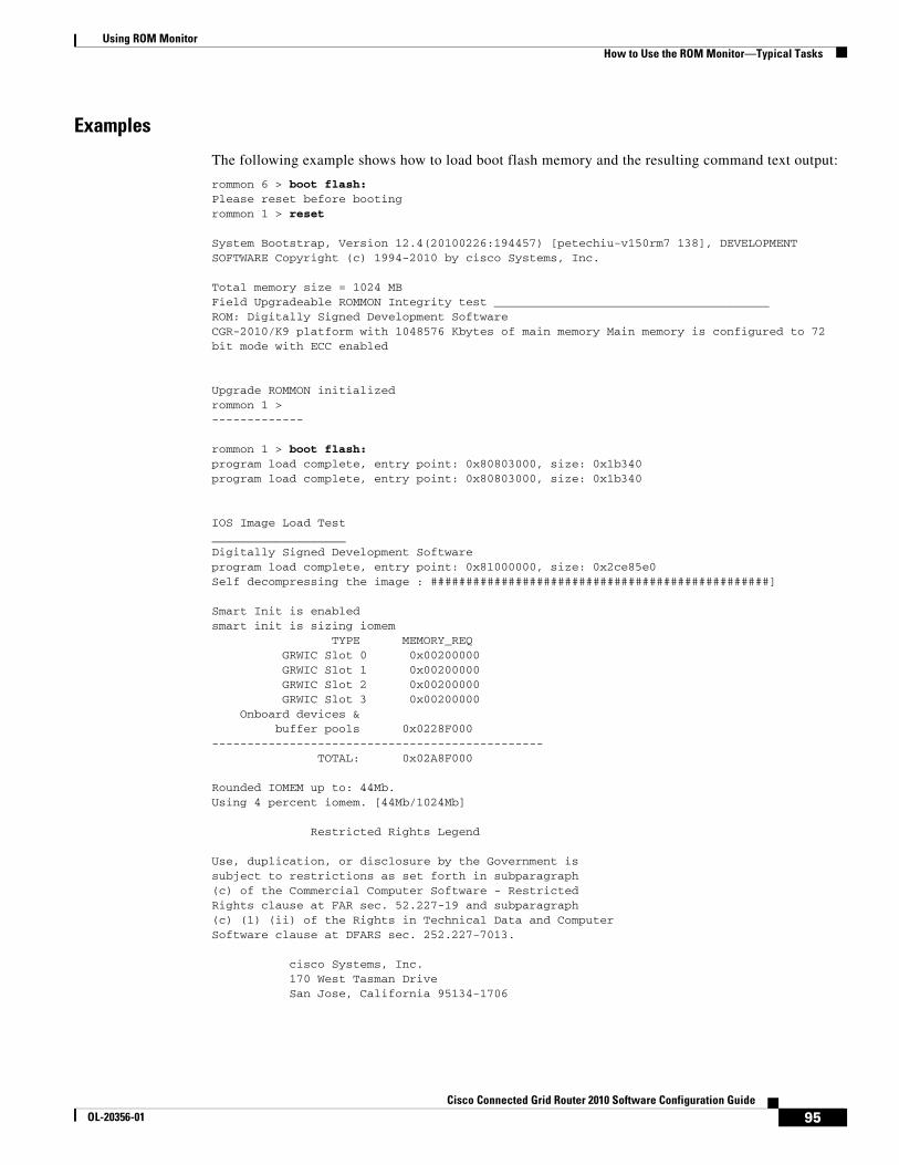
Using ROM MonitorHow to Use the ROM Monitor—Typical Tasks
Examples
The following example shows how to load boot flash memory and the resulting command text output:
rommon 6 > boot flash:Please reset before bootingrommon 1 > reset
System Bootstrap, Version 12.4(20100226:194457) [petechiu-v150rm7 138], DEVELOPMENT SOFTWARE Copyright (c) 1994-2010 by cisco Systems, Inc.
Total memory size = 1024 MBField Upgradeable ROMMON Integrity test _______________________________________ROM: Digitally Signed Development SoftwareCGR-2010/K9 platform with 1048576 Kbytes of main memory Main memory is configured to 72 bit mode with ECC enabled
Upgrade ROMMON initializedrommon 1 >-------------
rommon 1 > boot flash:program load complete, entry point: 0x80803000, size: 0x1b340program load complete, entry point: 0x80803000, size: 0x1b340
IOS Image Load Test ___________________ Digitally Signed Development Software program load complete, entry point: 0x81000000, size: 0x2ce85e0Self decompressing the image : ################################################]
Smart Init is enabledsmart init is sizing iomem TYPE MEMORY_REQ GRWIC Slot 0 0x00200000 GRWIC Slot 1 0x00200000 GRWIC Slot 2 0x00200000 GRWIC Slot 3 0x00200000 Onboard devices & buffer pools 0x0228F000 ----------------------------------------------- TOTAL: 0x02A8F000
Rounded IOMEM up to: 44Mb.Using 4 percent iomem. [44Mb/1024Mb]
Restricted Rights Legend
Use, duplication, or disclosure by the Government issubject to restrictions as set forth in subparagraph(c) of the Commercial Computer Software - RestrictedRights clause at FAR sec. 52.227-19 and subparagraph(c) (1) (ii) of the Rights in Technical Data and ComputerSoftware clause at DFARS sec. 252.227-7013.
cisco Systems, Inc. 170 West Tasman Drive San Jose, California 95134-1706
95Cisco Connected Grid Router 2010 Software Configuration Guide
OL-20356-01
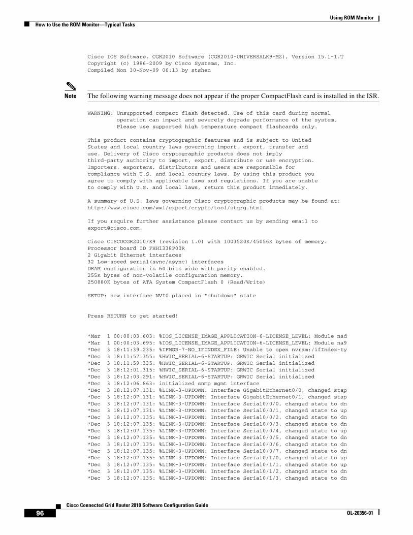
Using ROM MonitorHow to Use the ROM Monitor—Typical Tasks
Cisco IOS Software, CGR2010 Software (CGR2010-UNIVERSALK9-MZ), Version 15.1-1.TCopyright (c) 1986-2009 by Cisco Systems, Inc.Compiled Mon 30-Nov-09 06:13 by stshen
Note The following warning message does not appear if the proper CompactFlash card is installed in the ISR.
WARNING: Unsupported compact flash detected. Use of this card during normal operation can impact and severely degrade performance of the system. Please use supported high temperature compact flashcards only.
This product contains cryptographic features and is subject to UnitedStates and local country laws governing import, export, transfer anduse. Delivery of Cisco cryptographic products does not implythird-party authority to import, export, distribute or use encryption.Importers, exporters, distributors and users are responsible forcompliance with U.S. and local country laws. By using this product youagree to comply with applicable laws and regulations. If you are unableto comply with U.S. and local laws, return this product immediately.
A summary of U.S. laws governing Cisco cryptographic products may be found at:http://www.cisco.com/wwl/export/crypto/tool/stqrg.html
If you require further assistance please contact us by sending email [email protected].
Cisco CISCOCGR2010/K9 (revision 1.0) with 1003520K/45056K bytes of memory.Processor board ID FHH1338P00R2 Gigabit Ethernet interfaces32 Low-speed serial(sync/async) interfacesDRAM configuration is 64 bits wide with parity enabled.255K bytes of non-volatile configuration memory.250880K bytes of ATA System CompactFlash 0 (Read/Write)
SETUP: new interface NVI0 placed in "shutdown" state
Press RETURN to get started!
*Mar 1 00:00:03.603: %IOS_LICENSE_IMAGE_APPLICATION-6-LICENSE_LEVEL: Module nad*Mar 1 00:00:03.695: %IOS_LICENSE_IMAGE_APPLICATION-6-LICENSE_LEVEL: Module na9*Dec 3 18:11:39.235: %IFMGR-7-NO_IFINDEX_FILE: Unable to open nvram:/ifIndex-ty*Dec 3 18:11:57.355: %HWIC_SERIAL-6-STARTUP: GRWIC Serial initialized*Dec 3 18:11:59.335: %HWIC_SERIAL-6-STARTUP: GRWIC Serial initialized*Dec 3 18:12:01.315: %HWIC_SERIAL-6-STARTUP: GRWIC Serial initialized*Dec 3 18:12:03.291: %HWIC_SERIAL-6-STARTUP: GRWIC Serial initialized*Dec 3 18:12:06.863: initialized snmp mgmt interface*Dec 3 18:12:07.131: %LINK-3-UPDOWN: Interface GigabitEthernet0/0, changed stap*Dec 3 18:12:07.131: %LINK-3-UPDOWN: Interface GigabitEthernet0/1, changed stap*Dec 3 18:12:07.131: %LINK-3-UPDOWN: Interface Serial0/0/0, changed state to dn*Dec 3 18:12:07.131: %LINK-3-UPDOWN: Interface Serial0/0/1, changed state to up*Dec 3 18:12:07.135: %LINK-3-UPDOWN: Interface Serial0/0/2, changed state to dn*Dec 3 18:12:07.135: %LINK-3-UPDOWN: Interface Serial0/0/3, changed state to dn*Dec 3 18:12:07.135: %LINK-3-UPDOWN: Interface Serial0/0/4, changed state to up*Dec 3 18:12:07.135: %LINK-3-UPDOWN: Interface Serial0/0/5, changed state to dn*Dec 3 18:12:07.135: %LINK-3-UPDOWN: Interface Serial0/0/6, changed state to dn*Dec 3 18:12:07.135: %LINK-3-UPDOWN: Interface Serial0/0/7, changed state to dn*Dec 3 18:12:07.135: %LINK-3-UPDOWN: Interface Serial0/1/0, changed state to up*Dec 3 18:12:07.135: %LINK-3-UPDOWN: Interface Serial0/1/1, changed state to up*Dec 3 18:12:07.135: %LINK-3-UPDOWN: Interface Serial0/1/2, changed state to dn*Dec 3 18:12:07.135: %LINK-3-UPDOWN: Interface Serial0/1/3, changed state to dn
96Cisco Connected Grid Router 2010 Software Configuration Guide
OL-20356-01
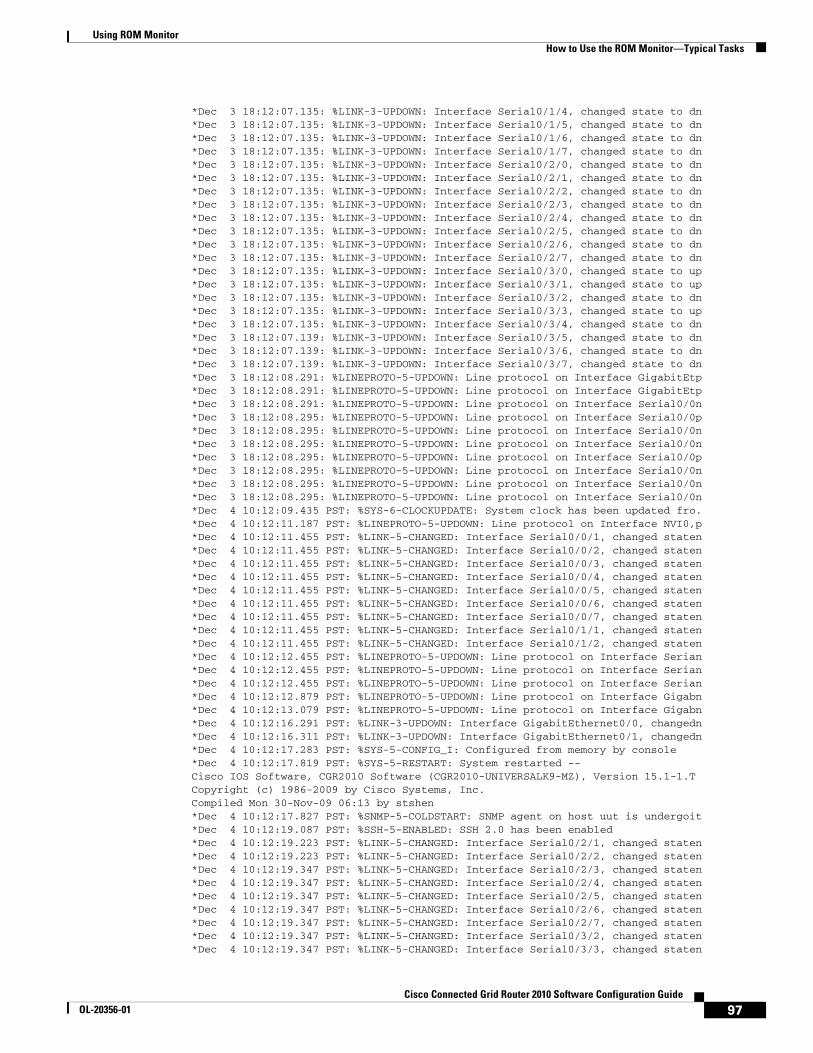
Using ROM MonitorHow to Use the ROM Monitor—Typical Tasks
*Dec 3 18:12:07.135: %LINK-3-UPDOWN: Interface Serial0/1/4, changed state to dn*Dec 3 18:12:07.135: %LINK-3-UPDOWN: Interface Serial0/1/5, changed state to dn*Dec 3 18:12:07.135: %LINK-3-UPDOWN: Interface Serial0/1/6, changed state to dn*Dec 3 18:12:07.135: %LINK-3-UPDOWN: Interface Serial0/1/7, changed state to dn*Dec 3 18:12:07.135: %LINK-3-UPDOWN: Interface Serial0/2/0, changed state to dn*Dec 3 18:12:07.135: %LINK-3-UPDOWN: Interface Serial0/2/1, changed state to dn*Dec 3 18:12:07.135: %LINK-3-UPDOWN: Interface Serial0/2/2, changed state to dn*Dec 3 18:12:07.135: %LINK-3-UPDOWN: Interface Serial0/2/3, changed state to dn*Dec 3 18:12:07.135: %LINK-3-UPDOWN: Interface Serial0/2/4, changed state to dn*Dec 3 18:12:07.135: %LINK-3-UPDOWN: Interface Serial0/2/5, changed state to dn*Dec 3 18:12:07.135: %LINK-3-UPDOWN: Interface Serial0/2/6, changed state to dn*Dec 3 18:12:07.135: %LINK-3-UPDOWN: Interface Serial0/2/7, changed state to dn*Dec 3 18:12:07.135: %LINK-3-UPDOWN: Interface Serial0/3/0, changed state to up*Dec 3 18:12:07.135: %LINK-3-UPDOWN: Interface Serial0/3/1, changed state to up*Dec 3 18:12:07.135: %LINK-3-UPDOWN: Interface Serial0/3/2, changed state to dn*Dec 3 18:12:07.135: %LINK-3-UPDOWN: Interface Serial0/3/3, changed state to up*Dec 3 18:12:07.135: %LINK-3-UPDOWN: Interface Serial0/3/4, changed state to dn*Dec 3 18:12:07.139: %LINK-3-UPDOWN: Interface Serial0/3/5, changed state to dn*Dec 3 18:12:07.139: %LINK-3-UPDOWN: Interface Serial0/3/6, changed state to dn*Dec 3 18:12:07.139: %LINK-3-UPDOWN: Interface Serial0/3/7, changed state to dn*Dec 3 18:12:08.291: %LINEPROTO-5-UPDOWN: Line protocol on Interface GigabitEtp*Dec 3 18:12:08.291: %LINEPROTO-5-UPDOWN: Line protocol on Interface GigabitEtp*Dec 3 18:12:08.291: %LINEPROTO-5-UPDOWN: Line protocol on Interface Serial0/0n*Dec 3 18:12:08.295: %LINEPROTO-5-UPDOWN: Line protocol on Interface Serial0/0p*Dec 3 18:12:08.295: %LINEPROTO-5-UPDOWN: Line protocol on Interface Serial0/0n*Dec 3 18:12:08.295: %LINEPROTO-5-UPDOWN: Line protocol on Interface Serial0/0n*Dec 3 18:12:08.295: %LINEPROTO-5-UPDOWN: Line protocol on Interface Serial0/0p*Dec 3 18:12:08.295: %LINEPROTO-5-UPDOWN: Line protocol on Interface Serial0/0n*Dec 3 18:12:08.295: %LINEPROTO-5-UPDOWN: Line protocol on Interface Serial0/0n*Dec 3 18:12:08.295: %LINEPROTO-5-UPDOWN: Line protocol on Interface Serial0/0n*Dec 4 10:12:09.435 PST: %SYS-6-CLOCKUPDATE: System clock has been updated fro.*Dec 4 10:12:11.187 PST: %LINEPROTO-5-UPDOWN: Line protocol on Interface NVI0,p*Dec 4 10:12:11.455 PST: %LINK-5-CHANGED: Interface Serial0/0/1, changed staten*Dec 4 10:12:11.455 PST: %LINK-5-CHANGED: Interface Serial0/0/2, changed staten*Dec 4 10:12:11.455 PST: %LINK-5-CHANGED: Interface Serial0/0/3, changed staten*Dec 4 10:12:11.455 PST: %LINK-5-CHANGED: Interface Serial0/0/4, changed staten*Dec 4 10:12:11.455 PST: %LINK-5-CHANGED: Interface Serial0/0/5, changed staten*Dec 4 10:12:11.455 PST: %LINK-5-CHANGED: Interface Serial0/0/6, changed staten*Dec 4 10:12:11.455 PST: %LINK-5-CHANGED: Interface Serial0/0/7, changed staten*Dec 4 10:12:11.455 PST: %LINK-5-CHANGED: Interface Serial0/1/1, changed staten*Dec 4 10:12:11.455 PST: %LINK-5-CHANGED: Interface Serial0/1/2, changed staten*Dec 4 10:12:12.455 PST: %LINEPROTO-5-UPDOWN: Line protocol on Interface Serian*Dec 4 10:12:12.455 PST: %LINEPROTO-5-UPDOWN: Line protocol on Interface Serian*Dec 4 10:12:12.455 PST: %LINEPROTO-5-UPDOWN: Line protocol on Interface Serian*Dec 4 10:12:12.879 PST: %LINEPROTO-5-UPDOWN: Line protocol on Interface Gigabn*Dec 4 10:12:13.079 PST: %LINEPROTO-5-UPDOWN: Line protocol on Interface Gigabn*Dec 4 10:12:16.291 PST: %LINK-3-UPDOWN: Interface GigabitEthernet0/0, changedn*Dec 4 10:12:16.311 PST: %LINK-3-UPDOWN: Interface GigabitEthernet0/1, changedn*Dec 4 10:12:17.283 PST: %SYS-5-CONFIG_I: Configured from memory by console*Dec 4 10:12:17.819 PST: %SYS-5-RESTART: System restarted --Cisco IOS Software, CGR2010 Software (CGR2010-UNIVERSALK9-MZ), Version 15.1-1.TCopyright (c) 1986-2009 by Cisco Systems, Inc.Compiled Mon 30-Nov-09 06:13 by stshen*Dec 4 10:12:17.827 PST: %SNMP-5-COLDSTART: SNMP agent on host uut is undergoit*Dec 4 10:12:19.087 PST: %SSH-5-ENABLED: SSH 2.0 has been enabled*Dec 4 10:12:19.223 PST: %LINK-5-CHANGED: Interface Serial0/2/1, changed staten*Dec 4 10:12:19.223 PST: %LINK-5-CHANGED: Interface Serial0/2/2, changed staten*Dec 4 10:12:19.347 PST: %LINK-5-CHANGED: Interface Serial0/2/3, changed staten*Dec 4 10:12:19.347 PST: %LINK-5-CHANGED: Interface Serial0/2/4, changed staten*Dec 4 10:12:19.347 PST: %LINK-5-CHANGED: Interface Serial0/2/5, changed staten*Dec 4 10:12:19.347 PST: %LINK-5-CHANGED: Interface Serial0/2/6, changed staten*Dec 4 10:12:19.347 PST: %LINK-5-CHANGED: Interface Serial0/2/7, changed staten*Dec 4 10:12:19.347 PST: %LINK-5-CHANGED: Interface Serial0/3/2, changed staten*Dec 4 10:12:19.347 PST: %LINK-5-CHANGED: Interface Serial0/3/3, changed staten
97Cisco Connected Grid Router 2010 Software Configuration Guide
OL-20356-01
Using ROM MonitorHow to Use the ROM Monitor—Typical Tasks
*Dec 4 10:12:19.347 PST: %LINK-5-CHANGED: Interface Serial0/3/4, changed staten*Dec 4 10:12:20.347 PST: %LINEPROTO-5-UPDOWN: Line protocol on Interface Serian*Dec 4 10:12:20.347 PST: %LINEPROTO-5-UPDOWN: Line protocol on Interface NVI0,nRouter>
What to Do Next
If you want to configure the router to load a specified image at the next system reload or power-cycle, see the following documents:
• Booting Commands” chapter of Cisco IOS Configuration Fundamentals Command Reference
• Cisco IOS Configuration Fundamentals and Network Management Configuration Guide
Modifying the Configuration RegisterThis section describes how to modify the configuration register using the confreg ROM monitor command. You can also modify the configuration register setting from the Cisco IOS CLI using the config-register command in global configuration mode.
Caution Do not set the configuration register using the config-register 0x0 command after setting the baud rate. To set the configuration register without affecting the baud rate, use the current configuration register setting by entering the show ver | inc configuration command and then replacing the last (rightmost) number with a 0 in the configuration register command.
Restrictions
The modified configuration register value is automatically written into NVRAM, but the new value does not take effect until you reset or power-cycle the router.
SUMMARY STEPS
1. confreg [value]
DETAILED STEPS
Examples
In the following example, the configuration register is set to boot the system image from flash memory:
Command or Action Purpose
Step 1 confreg [value]
Example:rommon > confreg 0x2102
Changes the configuration register settings while in ROM monitor mode.
• Optionally, enter the new hexadecimal value for the configuration register. The value range is from 0x0 to 0xFFFF.
• If you do not enter the value, the router prompts for each bit of the 16-bit configuration register.
98Cisco Connected Grid Router 2010 Software Configuration Guide
OL-20356-01
Using ROM MonitorHow to Use the ROM Monitor—Typical Tasks
rommon 3 > confreg 0x2102
In the following example, no value is entered; therefore, the system prompts for each bit in the register:
rommon 4 > confreg
Configuration Summary (Virtual Configuration Register: 0x2102)enabled are:load rom after netboot failsconsole baud: 9600boot: image specified by the boot system commands or default to: cisco2-CISCOCGR2010/K9
do you wish to change the configuration? y/n [n]: yenable "diagnostic mode"? y/n [n]: yenable "use net in IP bcast address"? y/n [n]: ydisable "load rom after netboot fails"? y/n [n]: yenable "use all zero broadcast"? y/n [n]: yenable "break/abort has effect"? y/n [n]: yenable "ignore system config info"? y/n [n]: ychange console baud rate? y/n [n]: y0=9600, 1=4800, 2=1200, 3=2400, 4=19200, 5=38400, 6=57600, 7=115200enter rate [0]: 0change the boot characteristics? y/n [n]: yenter to boot: 0 = ROM Monitor 1 = the boot helper image 2-15 = boot system [2]: 0
Configuration Summary (Virtual Configuration Register: 0xc440)enabled are:diagnostic modeuse net in IP bcast addressuse all zero broadcastbreak/abort has effectignore system config infoconsole baud: 9600boot: the ROM Monitor
do you wish to change the configuration? y/n [n]: <cr>You must reset or power cycle for new config to take effectrommon 5 >
Obtaining Information on USB Flash DevicesThis section describes how to obtain information on USB devices that are installed in the router. For instructions on booting from a USB flash device, see the “Loading a System Image (boot)” section on page 93.
SUMMARY STEPS
1. dir usbflash [x]:
2. dev
99Cisco Connected Grid Router 2010 Software Configuration Guide
OL-20356-01
Using ROM MonitorHow to Use the ROM Monitor—Typical Tasks
DETAILED STEPS
Examples
Sample Output for the dir usbFlash Command
In some cases, you need to use the reset command first.
rommon 8 > dir usbflash:Please reset before executing this commandrommon 9 > reset
System Bootstrap, Version 12.4(20100226:194457) [petechiu-v150rm7 138], DEVELOPMENT SOFTWARE Copyright (c) 1994-2010 by cisco Systems, Inc.
Total memory size = 1024 MBField Upgradeable ROMMON Integrity test _______________________________________ROM: Digitally Signed Development SoftwareCGR-2010/K9 platform with 1048576 Kbytes of main memory Main memory is configured to 72 bit mode with ECC enabled
Upgrade ROMMON initializedrommon 1 >-------------
Upgrade ROMMON initializedrommon 1 > dir usbflash:program load complete, entry point: 0x80903000, size: 0x4c440open(): Open Error = -1dir: cannot open device "usbflash:"
Note The Cisco CGR 2010 in this example does not have USB flash.
Modifying the I/O Memory (iomemset)This section describes how to modify the I/O memory percentage setting using the memory-size iomemset command.
Command or Action Purpose
Step 1 dir usbflash [x]:
Example:rommon > dir usbflash1:
Displays the contents of the USB flash device, including directories, files, permissions, and sizes.
• 0—USB flash device inserted in port 0
• 1—USB flash device inserted in port 1
Step 2 dev
Example:ROMMON > dev
Shows the targeted USB flash devices that are inserted in the router and the valid device names that may or may not be currently inserted.
100Cisco Connected Grid Router 2010 Software Configuration Guide
OL-20356-01
Using ROM MonitorHow to Use the ROM Monitor—Typical Tasks
Note Use the iomemset command only if it is needed for temporarily setting the I/O memory percentage from ROM monitor mode. Using this command improperly can adversely affect the functioning of the router.
The Cisco IOS software can override the I/O memory percentage if the memory-size iomem command is set in the NVRAM configuration. If the Cisco IOS command is present in the NVRAM configuration, the I/O memory percentage set in the ROM monitor with the iomemset command is used only the first time the router is booted up. Subsequent reloads use the I/O memory percentage set using the memory-size iomem command that is saved in the NVRAM configuration.
If you need to set the router I/O memory permanently using a manual method, use the memory-size iomem Cisco IOS command. If you set the I/O memory percentage from the Cisco IOS software, you must restart the router for I/O memory to be properly set.
SUMMARY STEPS
1. iomemset i/o-memory percentage
DETAILED STEPS
Examples
In the following example, the percentage of DRAM used for I/O memory is set to 15:
rommon 2 > iomemsetusage: iomemset [smartinit | 5 | 10 | 15 | 20 | 25 | 30 | 40 | 50 ]rommon 3 >rommon 3 > iomemset 15
Invoking this command will change the io memory percent*****WARNING:IOS may not keep this value*****Do you wish to continue? y/n: [n]: y
rommon 2 > meminfo------------------------------------------Current Memory configuration is: On-board: Size = 1024 MB: Start Phy Addr = 0x00000000_00000000-------------------------------------------------Main memory size: 1024 MB in 72 bit mode.Available main memory starts at 0x81000000, size 1032192KBSmart Init is enabled.NVRAM size: 256KB
Manufacturer's JEDEC ID code:On-board: rommon 3 >
Command or Action Purpose
Step 1 iomemset i/o-memory percentage
Example:rommon> iomemset 15
• Reallocates the percentage of DRAM used for I/O memory and processor memory.
101Cisco Connected Grid Router 2010 Software Configuration Guide
OL-20356-01
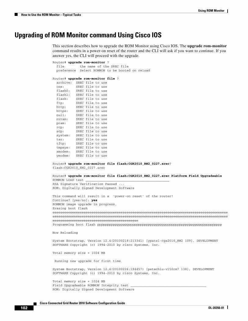
Using ROM MonitorHow to Use the ROM Monitor—Typical Tasks
Upgrading of ROM Monitor command Using Cisco IOSThis section describes how to upgrade the ROM Monitor using Cisco IOS. The upgrade rom-monitor command results in a power-on reset of the router and the CLI will ask if you want to continue. If you answer yes, the CLI will proceed with the upgrade.
Router# upgrade rom-monitor ? file the name of the SREC file preference Select ROMMON to be booted on reload
Router# upgrade rom-monitor file ? archive: SREC file to use cns: SREC file to use flash0: SREC file to use flash1: SREC file to use flash: SREC file to use ftp: SREC file to use http: SREC file to use https: SREC file to use null: SREC file to use nvram: SREC file to use pram: SREC file to use rcp: SREC file to use scp: SREC file to use system: SREC file to use tar: SREC file to use tftp: SREC file to use tmpsys: SREC file to use xmodem: SREC file to use ymodem: SREC file to use
Router# upgrade rom-monitor file flash:CGR2010_RM2_0227.srec?flash:CGR2010_RM2_0227.srec
Router# upgrade rom-monitor file flash:CGR2010_RM2_0227.srec Platform Field Upgradeable ROMMON LOAD test ___________________________________________RSA Signature Verification Passed ...ROM: Digitally Signed Development Software
This command will result in a 'power-on reset' of the router! Continue? [yes/no]: yesROMMON image upgrade in progress.Erasing boot flash eeeeeeeeeeeeeeeeeeeeeeeeeeeeeeeeeeeeeeeeeeeeeeeeeeeeeeeeeeeeeeeeeeeeeeeeeeeeeeeeeeeeeeeeeeeeeeeeeeeeeeeeeeeeeeeeeeeeeeeeeeeeeeeeeeeeeeeeeeeeeeeeeeeeeeeeeeeeeeeeeeeeeeeeeeeeeeeeeeeeeeeeeeeeeeeeeeeeeeeeeeeeeeeeeeeeeeeeeeeeeeeeProgramming boot flash pppppppppppppppppppppppppppppppppppppppppppppppppppppppppppppppp
Now Reloading
System Bootstrap, Version 12.4(20100218:213341) [ypatel-cgs2010_RM2 109], DEVELOPMENT SOFTWARE Copyright (c) 1994-2010 by cisco Systems, Inc.
Total memory size = 1024 MB
Running new upgrade for first time
System Bootstrap, Version 12.4(20100226:194457) [petechiu-v150rm7 138], DEVELOPMENT SOFTWARE Copyright (c) 1994-2010 by cisco Systems, Inc.
Total memory size = 1024 MBField Upgradeable ROMMON Integrity test _______________________________________ROM: Digitally Signed Development Software
102Cisco Connected Grid Router 2010 Software Configuration Guide
OL-20356-01
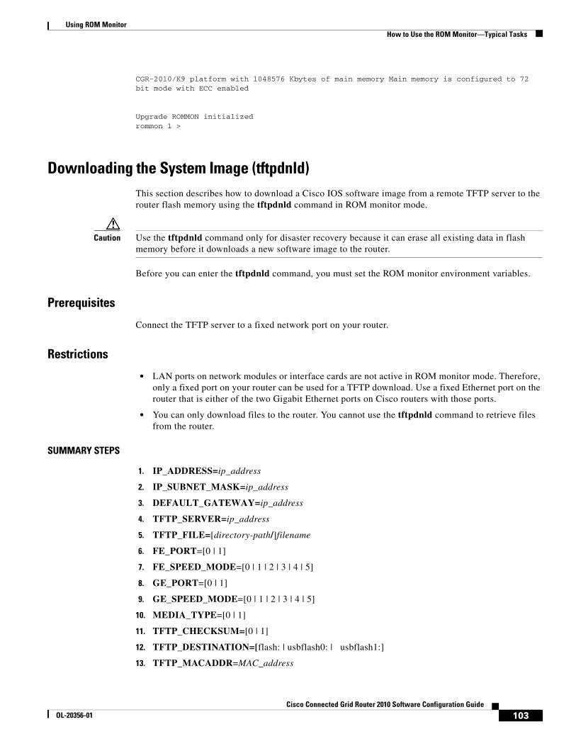
Using ROM MonitorHow to Use the ROM Monitor—Typical Tasks
CGR-2010/K9 platform with 1048576 Kbytes of main memory Main memory is configured to 72 bit mode with ECC enabled
Upgrade ROMMON initializedrommon 1 >
Downloading the System Image (tftpdnld)This section describes how to download a Cisco IOS software image from a remote TFTP server to the router flash memory using the tftpdnld command in ROM monitor mode.
Caution Use the tftpdnld command only for disaster recovery because it can erase all existing data in flash memory before it downloads a new software image to the router.
Before you can enter the tftpdnld command, you must set the ROM monitor environment variables.
Prerequisites
Connect the TFTP server to a fixed network port on your router.
Restrictions
• LAN ports on network modules or interface cards are not active in ROM monitor mode. Therefore, only a fixed port on your router can be used for a TFTP download. Use a fixed Ethernet port on the router that is either of the two Gigabit Ethernet ports on Cisco routers with those ports.
• You can only download files to the router. You cannot use the tftpdnld command to retrieve files from the router.
SUMMARY STEPS
1. IP_ADDRESS=ip_address
2. IP_SUBNET_MASK=ip_address
3. DEFAULT_GATEWAY=ip_address
4. TFTP_SERVER=ip_address
5. TFTP_FILE=[directory-path/]filename
6. FE_PORT=[0 | 1]
7. FE_SPEED_MODE=[0 | 1 | 2 | 3 | 4 | 5]
8. GE_PORT=[0 | 1]
9. GE_SPEED_MODE=[0 | 1 | 2 | 3 | 4 | 5]
10. MEDIA_TYPE=[0 | 1]
11. TFTP_CHECKSUM=[0 | 1]
12. TFTP_DESTINATION=[flash: | usbflash0: | usbflash1:]
13. TFTP_MACADDR=MAC_address
103Cisco Connected Grid Router 2010 Software Configuration Guide
OL-20356-01
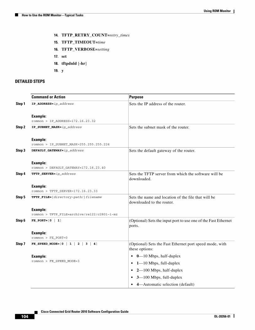
Using ROM MonitorHow to Use the ROM Monitor—Typical Tasks
14. TFTP_RETRY_COUNT=retry_times
15. TFTP_TIMEOUT=time
16. TFTP_VERBOSE=setting
17. set
18. tftpdnld [-hr]
19. y
DETAILED STEPS
Command or Action Purpose
Step 1 IP_ADDRESS=ip_address
Example:rommon > IP_ADDRESS=172.16.23.32
Sets the IP address of the router.
Step 2 IP_SUBNET_MASK=ip_address
Example:rommon > IP_SUBNET_MASK=255.255.255.224
Sets the subnet mask of the router.
Step 3 DEFAULT_GATEWAY=ip_address
Example:rommon > DEFAULT_GATEWAY=172.16.23.40
Sets the default gateway of the router.
Step 4 TFTP_SERVER=ip_address
Example:rommon > TFTP_SERVER=172.16.23.33
Sets the TFTP server from which the software will be downloaded.
Step 5 TFTP_FILE=[directory-path/]filename
Example:rommon > TFTP_FILE=archive/rel22/c2801-i-mz
Sets the name and location of the file that will be downloaded to the router.
Step 6 FE_PORT=[0 | 1]
Example:rommon > FE_PORT=0
(Optional) Sets the input port to use one of the Fast Ethernet ports.
Step 7 FE_SPEED_MODE=[0 | 1 | 2 | 3 | 4]
Example:rommon > FE_SPEED_MODE=3
(Optional) Sets the Fast Ethernet port speed mode, with these options:
• 0—10 Mbps, half-duplex
• 1—10 Mbps, full-duplex
• 2—100 Mbps, half-duplex
• 3—100 Mbps, full-duplex
• 4—Automatic selection (default)
104Cisco Connected Grid Router 2010 Software Configuration Guide
OL-20356-01

Using ROM MonitorHow to Use the ROM Monitor—Typical Tasks
Step 8 GE_PORT=[0 | 1]
Example:rommon > GE_PORT=0
(Optional) Sets the input port to use one of the Gigabit Ethernet ports.
Step 9 GE_SPEED_MODE=[0 | 1 | 2 | 3 | 4 | 5]
Example:rommon > GE_SPEED_MODE=3
(Optional) Sets the Gigabit Ethernet port speed mode, with these options:
• 0—10 Mbps, half-duplex
• 1—10 Mbps, full-duplex
• 2—100 Mbps, half-duplex
• 3—100 Mbps, full-duplex
• 4—1 Gbps, full-duplex
• 5—Automatic selection (default)
Step 10 MEDIA_TYPE=[0 | 1]
Example:rommon > MEDIA_TYPE=1
(Optional) Sets the Gigabit Ethernet connection media type, RJ-45 (0) or SFP (1). Small form-factor pluggable (SFP) mode is applicable only if GE_PORT=0 (gig 0/0); RJ-45 mode is available on both gig 0/0 and gig 0/1 (GE_PORT = 0 or 1).
Step 11 TFTP_CHECKSUM=[0 | 1]
Example:rommon > TFTP_CHECKSUM=0
(Optional) Determines whether the router performs a checksum test on the downloaded image.
• 1—Checksum test is performed (default).
• 0—No checksum test is performed.
Step 12 TFTP_DESTINATION=[flash: | usbflash0: | usbflash1:]
Example:rommon > TFTP_DESTINATION=usbflash0:
(Optional) Designates the targeted flash device as compact flash or USB flash.
• flash:—Compact flash device (default).
• usbflash0:—USB flash device inserted in port 0
• usbflash1:—USB flash device inserted in port 1
Step 13 TFTP_MACADDR=MAC_address
Example:rommon > TFTP_MACADDR=000e.8335.f360
(Optional) Sets the Media Access Controller (MAC) address for this router.
Step 14 TFTP_RETRY_COUNT=retry_times
Example:rommon > TFTP_RETRY_COUNT=10
(Optional) Sets the number of times that the router attempts Address Resolution Protocol (ARP) and TFTP download. The default is 7.
Step 15 TFTP_TIMEOUT=time
Example:TFTP_TIMEOUT=1800
(Optional) Sets the amount of time, in seconds, before the download process times out. The default is 2400 seconds (40 minutes).
Command or Action Purpose
105Cisco Connected Grid Router 2010 Software Configuration Guide
OL-20356-01
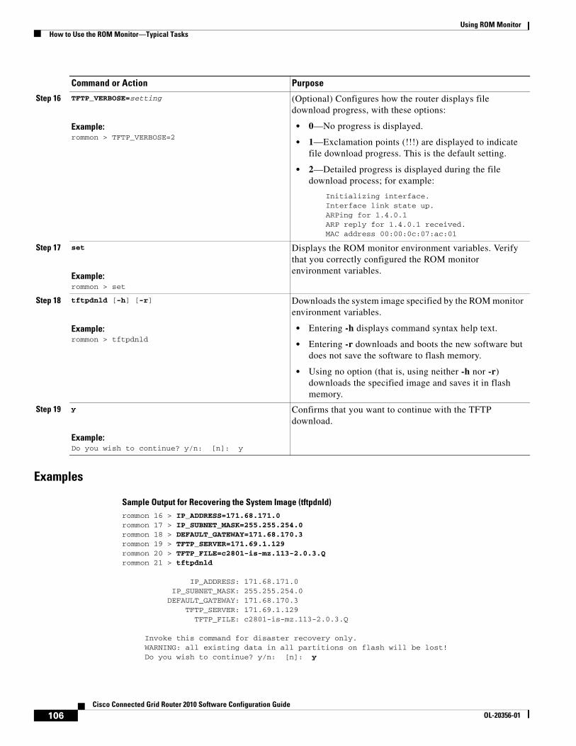
Using ROM MonitorHow to Use the ROM Monitor—Typical Tasks
Examples
Sample Output for Recovering the System Image (tftpdnld)rommon 16 > IP_ADDRESS=171.68.171.0 rommon 17 > IP_SUBNET_MASK=255.255.254.0 rommon 18 > DEFAULT_GATEWAY=171.68.170.3 rommon 19 > TFTP_SERVER=171.69.1.129 rommon 20 > TFTP_FILE=c2801-is-mz.113-2.0.3.Q rommon 21 > tftpdnld
IP_ADDRESS: 171.68.171.0 IP_SUBNET_MASK: 255.255.254.0 DEFAULT_GATEWAY: 171.68.170.3 TFTP_SERVER: 171.69.1.129 TFTP_FILE: c2801-is-mz.113-2.0.3.Q
Invoke this command for disaster recovery only. WARNING: all existing data in all partitions on flash will be lost! Do you wish to continue? y/n: [n]: y
Step 16 TFTP_VERBOSE=setting
Example:rommon > TFTP_VERBOSE=2
(Optional) Configures how the router displays file download progress, with these options:
• 0—No progress is displayed.
• 1—Exclamation points (!!!) are displayed to indicate file download progress. This is the default setting.
• 2—Detailed progress is displayed during the file download process; for example:
Initializing interface.Interface link state up.ARPing for 1.4.0.1ARP reply for 1.4.0.1 received. MAC address 00:00:0c:07:ac:01
Step 17 set
Example:rommon > set
Displays the ROM monitor environment variables. Verify that you correctly configured the ROM monitor environment variables.
Step 18 tftpdnld [-h] [-r]
Example:rommon > tftpdnld
Downloads the system image specified by the ROM monitor environment variables.
• Entering -h displays command syntax help text.
• Entering -r downloads and boots the new software but does not save the software to flash memory.
• Using no option (that is, using neither -h nor -r) downloads the specified image and saves it in flash memory.
Step 19 y
Example:Do you wish to continue? y/n: [n]: y
Confirms that you want to continue with the TFTP download.
Command or Action Purpose
106Cisco Connected Grid Router 2010 Software Configuration Guide
OL-20356-01
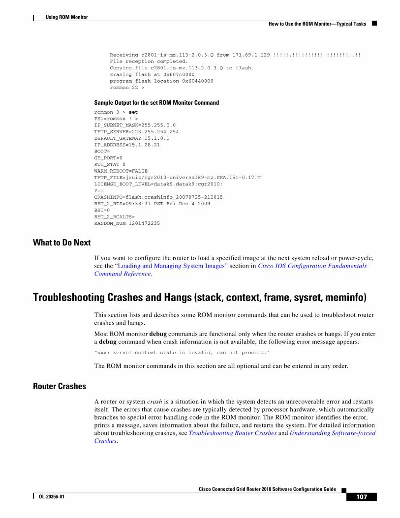
Using ROM MonitorHow to Use the ROM Monitor—Typical Tasks
Receiving c2801-is-mz.113-2.0.3.Q from 171.69.1.129 !!!!!.!!!!!!!!!!!!!!!!!!!.!! File reception completed. Copying file c2801-is-mz.113-2.0.3.Q to flash. Erasing flash at 0x607c0000 program flash location 0x60440000 rommon 22 >
Sample Output for the set ROM Monitor Commandrommon 3 > set PS1=rommon ! > IP_SUBNET_MASK=255.255.0.0TFTP_SERVER=223.255.254.254DEFAULT_GATEWAY=15.1.0.1IP_ADDRESS=15.1.28.21BOOT=GE_PORT=0RTC_STAT=0WARM_REBOOT=FALSETFTP_FILE=jruiz/cgr2010-universalk9-mz.SSA.151-0.17.TLICENSE_BOOT_LEVEL=datak9,datak9:cgr2010;?=1CRASHINFO=flash:crashinfo_20070725-212015RET_2_RTS=09:38:37 PST Fri Dec 4 2009BSI=0RET_2_RCALTS=RANDOM_NUM=1201472235
What to Do Next
If you want to configure the router to load a specified image at the next system reload or power-cycle, see the “Loading and Managing System Images” section in Cisco IOS Configuration Fundamentals Command Reference.
Troubleshooting Crashes and Hangs (stack, context, frame, sysret, meminfo)This section lists and describes some ROM monitor commands that can be used to troubleshoot router crashes and hangs.
Most ROM monitor debug commands are functional only when the router crashes or hangs. If you enter a debug command when crash information is not available, the following error message appears:
"xxx: kernel context state is invalid, can not proceed."
The ROM monitor commands in this section are all optional and can be entered in any order.
Router Crashes
A router or system crash is a situation in which the system detects an unrecoverable error and restarts itself. The errors that cause crashes are typically detected by processor hardware, which automatically branches to special error-handling code in the ROM monitor. The ROM monitor identifies the error, prints a message, saves information about the failure, and restarts the system. For detailed information about troubleshooting crashes, see Troubleshooting Router Crashes and Understanding Software-forced Crashes.
107Cisco Connected Grid Router 2010 Software Configuration Guide
OL-20356-01
Using ROM MonitorHow to Use the ROM Monitor—Typical Tasks
Router Hangs
A router or system hang is a situation in which the system does not respond to input at the console port or to queries, such as Telnet and SNMP, sent from the network.
Router hangs occur when:
• The console does not respond
• Traffic does not pass through the router
Router hangs are discussed in detail in Troubleshooting Router Hangs.
ROM Monitor Console Communication Failure
Under certain configuration situations where there is improper configuration, it can be impossible to establish a console connection with the router because of a speed mismatch or other incompatibility. The most obvious symptom is a set of erroneous characters in the console display.
If a ROM monitor failure of this type occurs, you may need to change a jumper setting on the motherboard so that the router can reboot for troubleshooting. Procedures for accessing the motherboard and jumper locations are described in the installation of internal components section of the hardware installation document for your router.
The jumper to be changed is DUART DFLT, which sets the console connection data baud rate to 9600, regardless of user configuration. The jumper forces the data rate to an acceptable value.
Restrictions
Do not manually reload or power-cycle the router unless reloading or power cycling is required for troubleshooting a router crash. System reload or power-cycle can cause important information that is needed for determining the root cause of the problem to be lost.
SUMMARY STEPS
1. stack ork
2. context
3. frame [number]
4. sysret
5. meminfo
108Cisco Connected Grid Router 2010 Software Configuration Guide
OL-20356-01
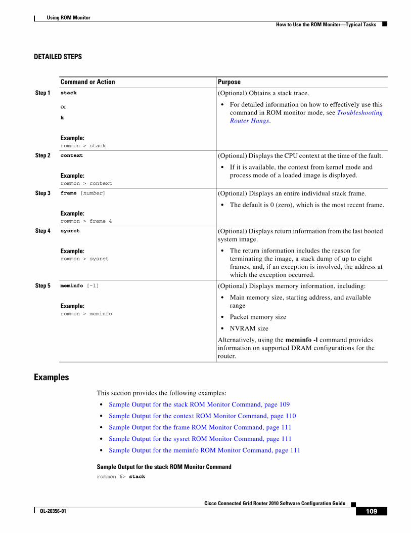
Using ROM MonitorHow to Use the ROM Monitor—Typical Tasks
DETAILED STEPS
Examples
This section provides the following examples:
• Sample Output for the stack ROM Monitor Command, page 109
• Sample Output for the context ROM Monitor Command, page 110
• Sample Output for the frame ROM Monitor Command, page 111
• Sample Output for the sysret ROM Monitor Command, page 111
• Sample Output for the meminfo ROM Monitor Command, page 111
Sample Output for the stack ROM Monitor Commandrommon 6> stack
Command or Action Purpose
Step 1 stack
or
k
Example:rommon > stack
(Optional) Obtains a stack trace.
• For detailed information on how to effectively use this command in ROM monitor mode, see Troubleshooting Router Hangs.
Step 2 context
Example:rommon > context
(Optional) Displays the CPU context at the time of the fault.
• If it is available, the context from kernel mode and process mode of a loaded image is displayed.
Step 3 frame [number]
Example:rommon > frame 4
(Optional) Displays an entire individual stack frame.
• The default is 0 (zero), which is the most recent frame.
Step 4 sysret
Example:rommon > sysret
(Optional) Displays return information from the last booted system image.
• The return information includes the reason for terminating the image, a stack dump of up to eight frames, and, if an exception is involved, the address at which the exception occurred.
Step 5 meminfo [-l]
Example:rommon > meminfo
(Optional) Displays memory information, including:
• Main memory size, starting address, and available range
• Packet memory size
• NVRAM size
Alternatively, using the meminfo -l command provides information on supported DRAM configurations for the router.
109Cisco Connected Grid Router 2010 Software Configuration Guide
OL-20356-01

Using ROM MonitorHow to Use the ROM Monitor—Typical Tasks
Kernel Level Stack Trace:Initial SP = 0x642190b8, Initial PC = 0x607a0d44, RA = 0x61d839f8Frame 0 : FP= 0x642190b8, PC= 0x607a0d44, 0 bytesFrame 1 : FP= 0x642190b8, PC= 0x61d839f8, 24 bytesFrame 2 : FP= 0x642190d0, PC= 0x6079b6c4, 40 bytesFrame 3 : FP= 0x642190f8, PC= 0x6079ff70, 32 bytesFrame 4 : FP= 0x64219118, PC= 0x6079eaec, 0 bytes
Process Level Stack Trace:Initial SP = 0x64049cb0, Initial PC = 0x60e3b7f4, RA = 0x60e36fa8Frame 0 : FP= 0x64049cb0, PC= 0x60e3b7f4, 24 bytesFrame 1 : FP= 0x64049cc8, PC= 0x60e36fa8, 24 bytesFrame 2 : FP= 0x64049ce0, PC= 0x607a5800, 432 bytesFrame 3 : FP= 0x64049e90, PC= 0x607a8988, 56 bytesFrame 4 : FP= 0x64049ec8, PC= 0x64049f14, 0 bytes
Sample Output for the context ROM Monitor Commandrommon 7> context Kernel Level Context: Reg MSW LSW | Reg MSW LSW------ ---------- ---------- | ----- ---------- ----------zero : 00000000 00000000 | s0 : 00000000 34018001AT : 00000000 24100000 | s1 : 00000000 00000001v0 : 00000000 00000003 | s2 : 00000000 00000003v1 : 00000000 00000000 | s3 : 00000000 00000000a0 : 00000000 0000002b | s4 : 00000000 64219118a1 : 00000000 00000003 | s5 : 00000000 62ad0000a2 : 00000000 00000000 | s6 : 00000000 63e10000a3 : 00000000 64219118 | s7 : 00000000 63e10000t0 : 00000000 00070808 | t8 : ffffffff e7400884t1 : 00000000 00000000 | t9 : 00000000 00000000t2 : 00000000 63e10000 | k0 : 00000000 00000000t3 : 00000000 34018001 | k1 : 00000000 63ab871ct4 : ffffffff ffff80fd | gp : 00000000 63c1c2d8t5 : ffffffff fffffffe | sp : 00000000 642190b8t6 : 00000000 3401ff02 | s8 : 00000000 6429274ct7 : 00000000 6408d464 | ra : 00000000 61d839f8HI : ffffffff e57fce22 | LO : ffffffff ea545255EPC : 00000000 607a0d44 | ErrPC : ffffffff bfc05f2cStat : 34018002 | Cause : 00000020
Process Level Context: Reg MSW LSW | Reg MSW LSW------ ---------- ---------- | ----- ---------- ----------zero : 00000000 00000000 | s0 : 00000000 6401a6f4AT : 00000000 63e10000 | s1 : 00000000 00000000v0 : 00000000 00000000 | s2 : 00000000 64049cf0v1 : 00000000 00000440 | s3 : 00000000 63360000a0 : 00000000 00000000 | s4 : 00000000 63360000a1 : 00000000 00070804 | s5 : 00000000 62ad0000a2 : 00000000 00000000 | s6 : 00000000 63e10000a3 : 00000000 00000000 | s7 : 00000000 63e10000t0 : 00000000 00000000 | t8 : ffffffff e7400884t1 : 00000000 64928378 | t9 : 00000000 00000000t2 : 00000000 00000001 | k0 : 00000000 644822e8t3 : ffffffff ffff00ff | k1 : 00000000 61d86d84t4 : 00000000 6079eee0 | gp : 00000000 63c1c2d8t5 : 00000000 00000001 | sp : 00000000 64049cb0t6 : 00000000 00000000 | s8 : 00000000 6429274ct7 : 00000000 6408d464 | ra : 00000000 60e36fa8HI : ffffffff e57fce22 | LO : ffffffff ea545255EPC : 00000000 60e3b7f4 | ErrPC : ffffffff ffffffffStat : 3401ff03 | Cause : ffffffff
110Cisco Connected Grid Router 2010 Software Configuration Guide
OL-20356-01
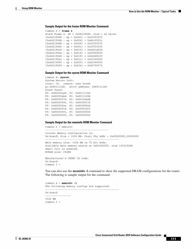
Using ROM MonitorHow to Use the ROM Monitor—Typical Tasks
Sample Output for the frame ROM Monitor Commandrommon 6 > frame 2 Stack Frame 2, SP = 0x642190d0, Size = 40 bytes[0x642190d0 : sp + 0x000] = 0xffffffff[0x642190d4 : sp + 0x004] = 0xbfc05f2c[0x642190d8 : sp + 0x008] = 0xffffffff[0x642190dc : sp + 0x00c] = 0xffffffff[0x642190e0 : sp + 0x010] = 0x6401a6f4[0x642190e4 : sp + 0x014] = 0x00000000[0x642190e8 : sp + 0x018] = 0x64049cf0[0x642190ec : sp + 0x01c] = 0x63360000[0x642190f0 : sp + 0x020] = 0x63360000[0x642190f4 : sp + 0x024] = 0x6079ff70
Sample Output for the sysret ROM Monitor Commandrommon 8> sysret System Return Info:count: 19, reason: user breakpc:0x801111b0, error address: 0x801111b0Stack Trace:FP: 0x80005ea8, PC: 0x801111b0FP: 0x80005eb4, PC: 0x80113694FP: 0x80005f74, PC: 0x8010eb44FP: 0x80005f9c, PC: 0x80008118FP: 0x80005fac, PC: 0x80008064FP: 0x80005fc4, PC: 0xfff03d70FP: 0x80005ffc, PC: 0x00000000FP: 0x00000000, PC: 0x00000000
Sample Output for the meminfo ROM Monitor Commandrommon 2 > meminfo------------------------------------------Current Memory configuration is: On-board: Size = 1024 MB: Start Phy Addr = 0x00000000_00000000-------------------------------------------------Main memory size: 1024 MB in 72 bit mode.Available main memory starts at 0x81000000, size 1032192KBSmart Init is enabled.NVRAM size: 256KB
Manufacturer's JEDEC ID code:On-board: rommon 3 >
You can also use the meminfo -l command to show the supported DRAM configurations for the router. The following is sample output for the command:
rommon 4 > meminfo -lThe following memory configs are supported:------------------------------------------------- On-board -----------------1024 MBrommon 3 >
111Cisco Connected Grid Router 2010 Software Configuration Guide
OL-20356-01
Using ROM MonitorHow to Use the ROM Monitor—Typical Tasks
Troubleshooting Tips
See the following documents:
• Troubleshooting Router Crashes
• Understanding Software-forced Crashes
• Troubleshooting Router Hangs
Exiting ROM Monitor ModeThis section describes how to exit ROM monitor mode and enter the Cisco IOS command-line interface (CLI). The method that you use to exit ROM monitor mode depends on how your router entered ROM monitor mode:
• If you reload the router and enter the Break key sequence to enter ROM monitor mode when the router would otherwise have booted the system image, you can exit ROM monitor mode by doing either of the following:
– Enter the i command or the reset command, which restarts the booting process and loads the system image.
– Enter the cont command, which continues the booting process and loads the system image.
• If your router entered ROM monitor mode because it could not locate and load the system image, perform the steps in the following procedure.
SUMMARY STEPS
1. dir flash: [directory]
2. boot flash: [directory] [filename] or boot filename tftpserver orboot [filename]
112Cisco Connected Grid Router 2010 Software Configuration Guide
OL-20356-01

Using ROM MonitorHow to Use the ROM Monitor—Typical Tasks
DETAILED STEPS
Examples
Sample Output for the dir flash: Command in ROM Monitor moderommon 2 > dir flash:program load complete, entry point: 0x80803000, size: 0x1b340Directory of flash:
2 47089944 -rw- cgr2010-universalk9-mz.SSA.151-0.17.Trommon 3 >
What to Do Next
If you want to configure the router to load a specified image at the next system reload or power-cycle, see the “Loading and Managing System Images” section in Cisco IOS Configuration Fundamentals Command Reference.
Command or Action Purpose
Step 1 dir flash:[directory]
Example:rommon > dir flash:
Displays a list of the files and directories in flash memory.
• Locate the system image that you want the router to load.
• If the system image is not in flash memory, use the second or third option in Step 2.
Step 2 boot flash:[directory] [filename]
or
boot filename tftpserver
or
boot [filename]
Example:ROMMON > boot flash:myimage
Example:ROMMON > boot someimage 172.16.30.40
Example:ROMMON > boot
In order, the examples here direct the router to:
• Boot the first image or a specified image in flash memory.
• Boot the specified image over the network from the specified TFTP server (hostname or IP address).
• Boot from the boothelper image because it does not recognize the device ID. This form of the command is used to netboot a specified image.
You can override the default boothelper image setting by setting the BOOTLDR Monitor environment variable to point to another image. Any system image can be used for this purpose.
Note Options to the boot command are -x (load image but do not execute) and -v (verbose).
113Cisco Connected Grid Router 2010 Software Configuration Guide
OL-20356-01

Using ROM MonitorAdditional References
Additional ReferencesThe following sections provide references related to using the ROM monitor.
Related Documents
Technical Assistance
Related Topic Document Title
Connecting your PC to the router console port Hardware installation guide for your router
Break key sequence combinations for entering ROM monitor mode within the first 60 seconds of rebooting the router
Standard Break Key Sequence Combinations During Password Recovery
Using the boot image (Rx-boot) to recover or upgrade the system image
How to Upgrade from ROMmon Using the Boot Image
Booting and configuration register commands Cisco IOS Configuration Fundamentals Command Reference
Loading and maintaining system images; rebooting Cisco IOS Configuration Fundamentals and Network Management Configuration Guide
Choosing and downloading system images Software Center at
http://www.cisco.com/kobayashi/sw-center/index.shtml
Router crashes Troubleshooting Router Crashes
Understanding Software-forced Crashes
Router hangs Troubleshooting Router Hangs
Description Link
Technical Assistance Center (TAC) home page, containing 30,000 pages of searchable technical content, including links to products, technologies, solutions, technical tips, and tools. Registered Cisco.com users can log in from this page to access even more content.1
1. You must have an account on Cisco.com. If you do not have an account or have forgotten your username or password, click Cancel at the login dialog box and follow the instructions that appear.
http://www.cisco.com/public/support/tac/home.shtml
114Cisco Connected Grid Router 2010 Software Configuration Guide
OL-20356-01
Changing the Configuration Register Settings
First Published: May 27, 2010, OL-20356-01Last Updated: October 25, 2017
This document describes the 16-bit configuration register in NVRAM in the following sections:
• Platforms this Document Supports, page 115
• About the Configuration Register, page 115
• Changing the Configuration Register Settings, page 118
• Displaying the Configuration Register Settings, page 119
• Configuring the Console Line Speed (Cisco IOS CLI), page 119
Platforms this Document SupportsThis document supports the Cisco Connected Grid Router 2010.
About the Configuration RegisterThe router has a 16-bit configuration register in NVRAM. Each bit has value 1 (on or set) or value 0 (off or clear), and each bit setting affects the router behavior upon the next reload power cycle.
You can use the configuration register to:
• Force the router to boot into the ROM monitor (bootstrap program)
• Select a boot source and default boot filename
• Enable or disable the Break function
• Control broadcast addresses
• Recover a lost password
• Change the console line speed
Table 1 describes the configuration register bits.
Americas Headquarters:Cisco Systems, Inc., 170 West Tasman Drive, San Jose, CA 95134-1706 USA
© 2010 Cisco Systems, Inc. All rights reserved.
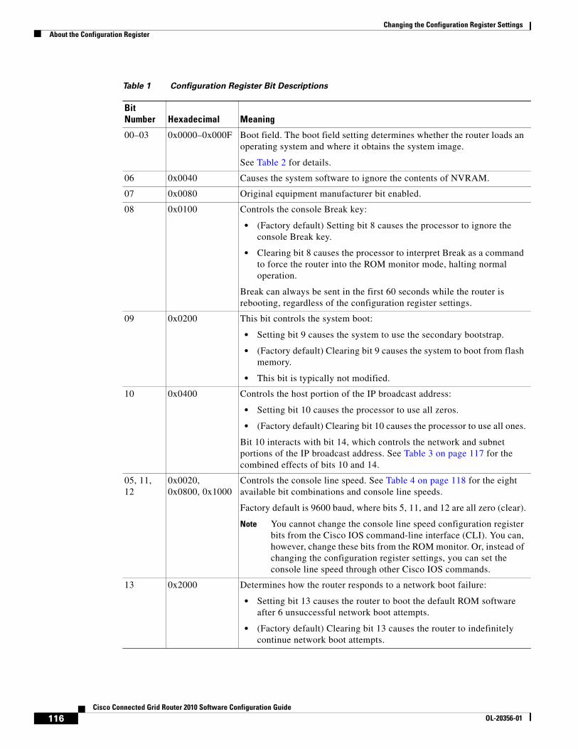
Changing the Configuration Register SettingsAbout the Configuration Register
Table 1 Configuration Register Bit Descriptions
BitNumber Hexadecimal Meaning
00–03 0x0000–0x000F Boot field. The boot field setting determines whether the router loads an operating system and where it obtains the system image.
See Table 2 for details.
06 0x0040 Causes the system software to ignore the contents of NVRAM.
07 0x0080 Original equipment manufacturer bit enabled.
08 0x0100 Controls the console Break key:
• (Factory default) Setting bit 8 causes the processor to ignore the console Break key.
• Clearing bit 8 causes the processor to interpret Break as a command to force the router into the ROM monitor mode, halting normal operation.
Break can always be sent in the first 60 seconds while the router is rebooting, regardless of the configuration register settings.
09 0x0200 This bit controls the system boot:
• Setting bit 9 causes the system to use the secondary bootstrap.
• (Factory default) Clearing bit 9 causes the system to boot from flash memory.
• This bit is typically not modified.
10 0x0400 Controls the host portion of the IP broadcast address:
• Setting bit 10 causes the processor to use all zeros.
• (Factory default) Clearing bit 10 causes the processor to use all ones.
Bit 10 interacts with bit 14, which controls the network and subnet portions of the IP broadcast address. See Table 3 on page 117 for the combined effects of bits 10 and 14.
05, 11, 12
0x0020, 0x0800, 0x1000
Controls the console line speed. See Table 4 on page 118 for the eight available bit combinations and console line speeds.
Factory default is 9600 baud, where bits 5, 11, and 12 are all zero (clear).
Note You cannot change the console line speed configuration register bits from the Cisco IOS command-line interface (CLI). You can, however, change these bits from the ROM monitor. Or, instead of changing the configuration register settings, you can set the console line speed through other Cisco IOS commands.
13 0x2000 Determines how the router responds to a network boot failure:
• Setting bit 13 causes the router to boot the default ROM software after 6 unsuccessful network boot attempts.
• (Factory default) Clearing bit 13 causes the router to indefinitely continue network boot attempts.
116Cisco Connected Grid Router 2010 Software Configuration Guide
OL-20356-01
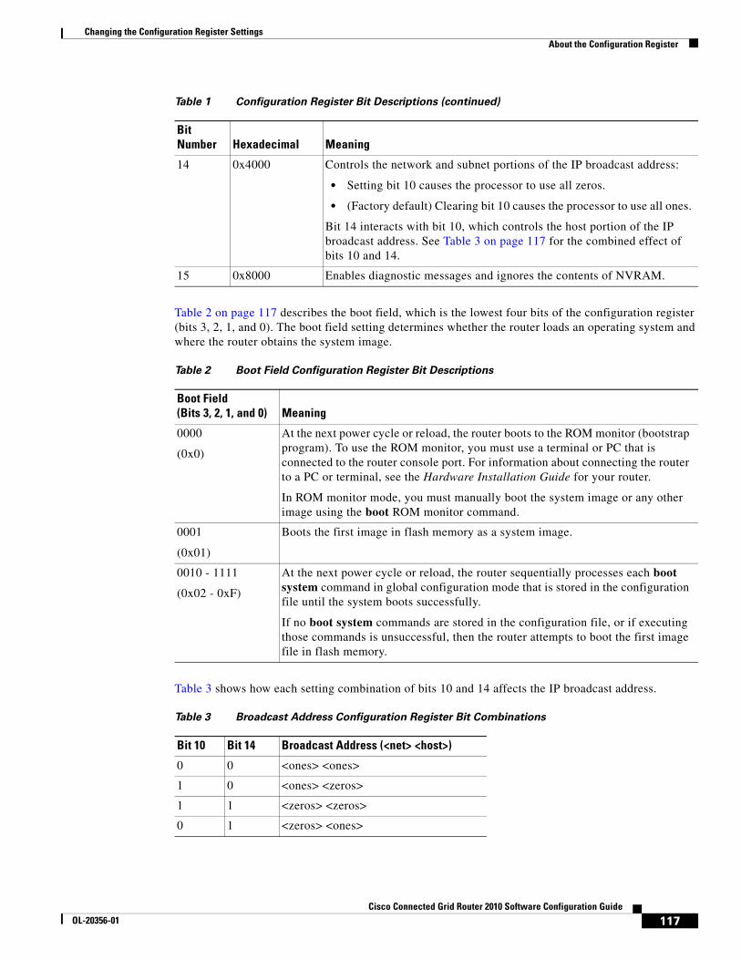
Changing the Configuration Register SettingsAbout the Configuration Register
Table 2 on page 117 describes the boot field, which is the lowest four bits of the configuration register (bits 3, 2, 1, and 0). The boot field setting determines whether the router loads an operating system and where the router obtains the system image.
Table 3 shows how each setting combination of bits 10 and 14 affects the IP broadcast address.
14 0x4000 Controls the network and subnet portions of the IP broadcast address:
• Setting bit 10 causes the processor to use all zeros.
• (Factory default) Clearing bit 10 causes the processor to use all ones.
Bit 14 interacts with bit 10, which controls the host portion of the IP broadcast address. See Table 3 on page 117 for the combined effect of bits 10 and 14.
15 0x8000 Enables diagnostic messages and ignores the contents of NVRAM.
Table 1 Configuration Register Bit Descriptions (continued)
BitNumber Hexadecimal Meaning
Table 2 Boot Field Configuration Register Bit Descriptions
Boot Field(Bits 3, 2, 1, and 0) Meaning
0000
(0x0)
At the next power cycle or reload, the router boots to the ROM monitor (bootstrap program). To use the ROM monitor, you must use a terminal or PC that is connected to the router console port. For information about connecting the router to a PC or terminal, see the Hardware Installation Guide for your router.
In ROM monitor mode, you must manually boot the system image or any other image using the boot ROM monitor command.
0001
(0x01)
Boots the first image in flash memory as a system image.
0010 - 1111
(0x02 - 0xF)
At the next power cycle or reload, the router sequentially processes each boot system command in global configuration mode that is stored in the configuration file until the system boots successfully.
If no boot system commands are stored in the configuration file, or if executing those commands is unsuccessful, then the router attempts to boot the first image file in flash memory.
Table 3 Broadcast Address Configuration Register Bit Combinations
Bit 10 Bit 14 Broadcast Address (<net> <host>)
0 0 <ones> <ones>
1 0 <ones> <zeros>
1 1 <zeros> <zeros>
0 1 <zeros> <ones>
117Cisco Connected Grid Router 2010 Software Configuration Guide
OL-20356-01
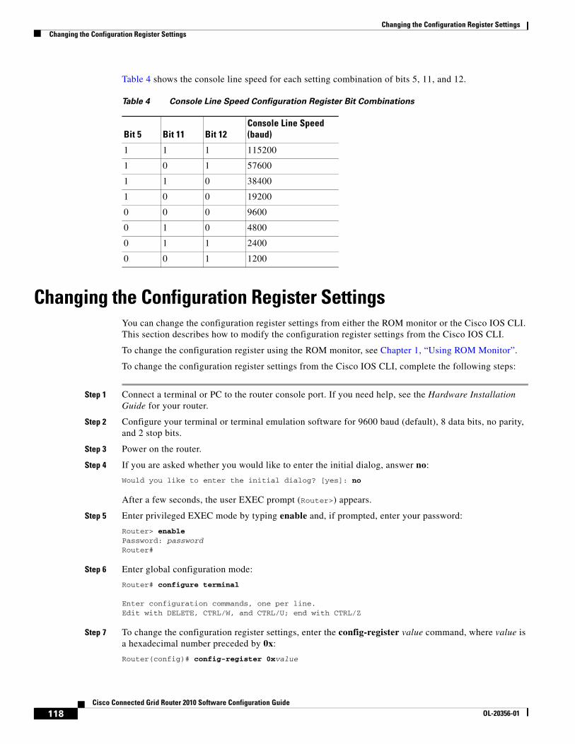
Changing the Configuration Register SettingsChanging the Configuration Register Settings
Table 4 shows the console line speed for each setting combination of bits 5, 11, and 12.
Changing the Configuration Register SettingsYou can change the configuration register settings from either the ROM monitor or the Cisco IOS CLI. This section describes how to modify the configuration register settings from the Cisco IOS CLI.
To change the configuration register using the ROM monitor, see Chapter 1, “Using ROM Monitor”.
To change the configuration register settings from the Cisco IOS CLI, complete the following steps:
Step 1 Connect a terminal or PC to the router console port. If you need help, see the Hardware Installation Guide for your router.
Step 2 Configure your terminal or terminal emulation software for 9600 baud (default), 8 data bits, no parity, and 2 stop bits.
Step 3 Power on the router.
Step 4 If you are asked whether you would like to enter the initial dialog, answer no:
Would you like to enter the initial dialog? [yes]: no
After a few seconds, the user EXEC prompt (Router>) appears.
Step 5 Enter privileged EXEC mode by typing enable and, if prompted, enter your password:
Router> enablePassword: passwordRouter#
Step 6 Enter global configuration mode:
Router# configure terminal
Enter configuration commands, one per line.Edit with DELETE, CTRL/W, and CTRL/U; end with CTRL/Z
Step 7 To change the configuration register settings, enter the config-register value command, where value is a hexadecimal number preceded by 0x:
Router(config)# config-register 0xvalue
Table 4 Console Line Speed Configuration Register Bit Combinations
Bit 5 Bit 11 Bit 12Console Line Speed (baud)
1 1 1 115200
1 0 1 57600
1 1 0 38400
1 0 0 19200
0 0 0 9600
0 1 0 4800
0 1 1 2400
0 0 1 1200
118Cisco Connected Grid Router 2010 Software Configuration Guide
OL-20356-01
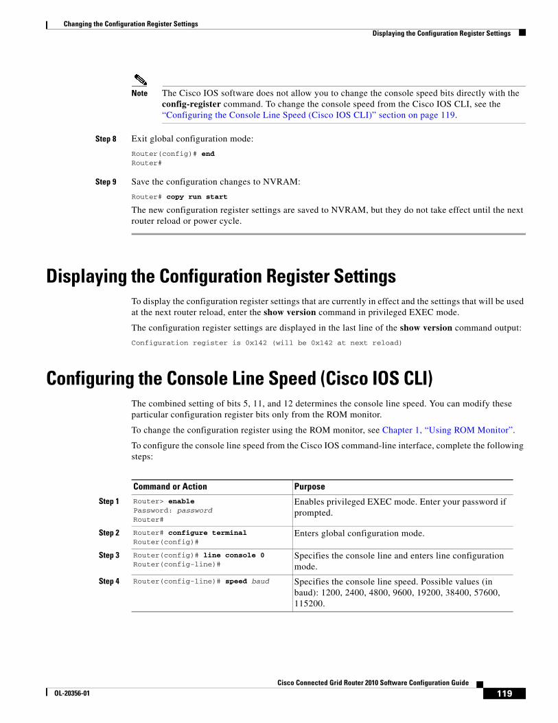
Changing the Configuration Register SettingsDisplaying the Configuration Register Settings
Note The Cisco IOS software does not allow you to change the console speed bits directly with the config-register command. To change the console speed from the Cisco IOS CLI, see the “Configuring the Console Line Speed (Cisco IOS CLI)” section on page 119.
Step 8 Exit global configuration mode:
Router(config)# endRouter#
Step 9 Save the configuration changes to NVRAM:
Router# copy run start
The new configuration register settings are saved to NVRAM, but they do not take effect until the next router reload or power cycle.
Displaying the Configuration Register SettingsTo display the configuration register settings that are currently in effect and the settings that will be used at the next router reload, enter the show version command in privileged EXEC mode.
The configuration register settings are displayed in the last line of the show version command output:
Configuration register is 0x142 (will be 0x142 at next reload)
Configuring the Console Line Speed (Cisco IOS CLI)The combined setting of bits 5, 11, and 12 determines the console line speed. You can modify these particular configuration register bits only from the ROM monitor.
To change the configuration register using the ROM monitor, see Chapter 1, “Using ROM Monitor”.
To configure the console line speed from the Cisco IOS command-line interface, complete the following steps:
Command or Action Purpose
Step 1 Router> enablePassword: passwordRouter#
Enables privileged EXEC mode. Enter your password if prompted.
Step 2 Router# configure terminalRouter(config)#
Enters global configuration mode.
Step 3 Router(config)# line console 0Router(config-line)#
Specifies the console line and enters line configuration mode.
Step 4 Router(config-line)# speed baud Specifies the console line speed. Possible values (in baud): 1200, 2400, 4800, 9600, 19200, 38400, 57600, 115200.
119Cisco Connected Grid Router 2010 Software Configuration Guide
OL-20356-01

Changing the Configuration Register SettingsConfiguring the Console Line Speed (Cisco IOS CLI)
120Cisco Connected Grid Router 2010 Software Configuration Guide
OL-20356-01
Cisco ConnecOL-20356-01
I N D E X
A
adequate flash memory to upgrade 59
advanced CompactFlash memory 2
assigning an interface IP address 16
auxiliary line configuration 24
auxiliary port, for dial backup 49
B
backing up startup configuration 57
backing up startup configuration file 27
baud rate
setting for console terminal 118
bridging, configuring 39
C
choosing Cisco IOS release 56
Cisco Configuration Professional Express 5, 11
Cisco IOS
choosing release 56
downloading images 57
upgrading image 57
command-line access configuration 39
commands
exec-timeout 16
CompactFlash
creating directories 81
deleting files 80
formatting 76
managing directories 81
online insertion/removal 76
removing directories 82
renaming files 80
requirements and restrictions 75
viewing file content 78
configuration example 52
configuration examples
dynamic routes 42
EIGRP 44
static route 41
configuration register
changing settings 118
configuring
auxiliary line 24
bridging 39
command-line access 39
default route 19
dynamic routes 42
EIGRP, IP 43 to 44
enable password 13
enable secret password 13
Gigabit Ethernet interfaces 36
global parameters 35
GRP 43
hostname 12
interface cards 37
interface description 16
IP EIGRP 43 to 44
loopback interface 37 to 38
modules 37
privileged EXEC timeout 15
RIP 42
RIP routes 42
static routes 40
I-1ted Grid Router 2010 Software Configuration Guide
Index
timeout 16
virtual terminal lines 22
console
USB 2
console port, for dial backup 49
copper connection
SFP/gigabit ethernet port 2
copying CompactFlash files 77
copying image using ROM monitor 64
creating CompactFlash directories 81
D
default
configuration, viewing 34
network 20
route configuration 19
routes 20
deleting files from CompactFlash 80
dial backup
configuring 49
displaying CompactFlash file content 78
displaying CompactFlash platform support status and errors 78
downloading Cisco IOS images 57
DRAM, adequate for upgrading 59
dynamic routes
configuration 42
configuration example 42
configuring 42
E
EIGRP configuration example 44
enable password configuration 13
enable secret password configuration 13
I-2Cisco Connected Grid Router 2010 Software Configuration Guide
F
failover redundancy 47
fiber connection
SFP/gigabit ethernet port 2
finding the IOS version 56
flash memory, adequate to upgrade 59
formatting CompactFlash 76
G
gateway of last resort 20
Gigabit Ethernet interfaces, configuring 36
Gigabit Ethernet ports 4
global parameters, setting up 35
grid router WAN interface cards
router slots 2
GRP configuration 43
H
hostname configuration 12
I
initial configuration setup 5
integrated routing and bridging configuration 19
interface card
configuration 37
interface description configuration 16
interface IP address assignment 16
interface port labels 36
IP routing 19
L
loading new system IOS image 67
loopback interface, configuring 37 to 38
OL-20356-01

Index
M
managing CompactFlash directories 81
memory
advanced CompactFlash 2
module configuration 37
modules
router slots 2
monitoring internal router temperature 29
N
network connectivity verification 26
new system IOS image, loading 67
O
online insertion/removal of CompactFlash 76
P
parameters, setting up global 35
port
SFP-GE 47
port labels for interfaces 36
ports
Gigabit Ethernet 4
RS232 4
USB 4
privileged EXEC timeout configuration 15
R
RCP, upgrading 62
release
new features 2
remote management, configuring 49
removing CompactFlash directories 82
CiscOL-20356-01
renaming CompactFlash files 80
RIP
configuring 42
RIP route configuration 42
ROM monitor, coping image 64
router, monitoring internal temperature 29
router slots 2
RS232 ports 4
S
saving router configuration 27
setup, initial 5
SFP/gigabit ethernet port
copper 2
fiber 2
SFP-GE port 47
show version command 56
slots 3
software upgrades, IOS 56
startup configuration, backing up 57
static route configuration 40
static routes
configuration 40
configuration example 41
configuring 40
T
Tables
configuration register settings for boot field 117
TFTP, upgrading 62
timeout, disabling 16
U
upgrading, adequate DRAM 59
upgrading Cisco IOS image 57
I-3 o Connected Grid Router 2010 Software Configuration Guide

Index
upgrading IOS software 56
USB
console 2
ports 4
using RCP to upgrade 62
using ROM monitor to copy image 64
using TFTP to upgrade 62
V
verifying
IP EIGRP configuration 44
network connectivity 26
RIP routing configuration 43
static route configuration 41
virtual terminal line configuration 22
I-4Cisco Connected Grid Router 2010 Software Configuration Guide
OL-20356-01