Embed Size (px)
Citation preview
¨
Cisco LightStream 1010 ATM SwitchManagement Module Guide

9032352 E1i
Notice
Cabletron Systems reserves the right to make changes in specifications and other information contained in this document without prior notice. The reader should in all cases consult Cabletron Systems to determine whether any such changes have been made.
The hardware, firmware, or software described in this manual is subject to change without notice.
IN NO EVENT SHALL CABLETRON SYSTEMS BE LIABLE FOR ANY INCIDENTAL, INDIRECT, SPECIAL, OR CONSEQUENTIAL DAMAGES WHATSOEVER (INCLUDING BUT NOT LIMITED TO LOST PROFITS) ARISING OUT OF OR RELATED TO THIS MANUAL OR THE INFORMATION CONTAINED IN IT, EVEN IF CABLETRON SYSTEMS HAS BEEN ADVISED OF, KNOWN, OR SHOULD HAVE KNOWN, THE POSSIBILITY OF SUCH DAMAGES.
Virus Disclaimer
Cabletron has tested its software with current virus checking technologies. However, because no anti-virus system is 100% reliable, we strongly caution you to write protect and then verify that the Licensed Software, prior to installing it, is virus-free with an anti-virus system in which you have confidence.
Cabletron Systems makes no representations or warranties to the effect that the Licensed Software is virus-free.
Copyright © February 1998, by Cabletron Systems, Inc. All rights reserved.
Printed in the United States of America.
Order Number: 9032352 E1
Cabletron Systems, Inc.P.O. Box 5005Rochester, NH 03866-5005
SPECTRUM
, the
SPECTRUM
IMT/VNM
logo,
DCM
,
IMT
, and
VNM
are registered trademarks, and
SpectroGRAPH
,
SpectroSERVER
,
Inductive Modeling Technology
,
Device Communications Manager
, and
Virtual Network Machine
are trademarks of Cabletron Systems, Inc.
Ethernet
is a trademark of Xerox Corporation.
LightStream
is a trademark of Cisco.
Cisco LightStream 1010 ATM Switchii Management Module Guide
Restricted Rights Notice
(Applicable to licenses to the United States Government only.)
1. Use, duplication, or disclosure by the Government is subject to restrictions as set forth in subparagraph (c) (1) (ii) of the Rights in Technical Data and Computer Software clause at DFARS 252.227-7013.
Cabletron Systems, Inc., 35 Industrial Way, Rochester, New Hampshire 03866-5005.
2. (a) This computer software is submitted with restricted rights. It may not be used, reproduced, or disclosed by the Government except as provided in paragraph (b) of this Notice or as otherwise expressly stated in the contract.
(b) This computer software may be:
(1) Used or copied for use in or with the computer or computers for which it was acquired, including use at any Government installation to which such computer or computers may be transferred;
(2) Used or copied for use in a backup computer if any computer for which it was acquired is inoperative;
(3) Reproduced for safekeeping (archives) or backup purposes;
(4) Modified, adapted, or combined with other computer software, provided that the modified, combined, or adapted portions of the derivative software incorporating restricted computer software are made subject to the same restricted rights;
(5) Disclosed to and reproduced for use by support service contractors in accordance with subparagraphs (b) (1) through (4) of this clause, provided the Government makes such disclosure or reproduction subject to these restricted rights; and
(6) Used or copied for use in or transferred to a replacement computer.
(c) Notwithstanding the foregoing, if this computer software is published copyrighted computer software, it is licensed to the Government, without disclosure prohibitions, with the minimum rights set forth in paragraph (b) of this clause.
(d) Any other rights or limitations regarding the use, duplication, or disclosure of this computer software are to be expressly stated in, or incorporated in, the contract.
(e) This Notice shall be marked on any reproduction of this computer software, in whole or in part.
9032352 E1iii
Contents
Preface
What Is in This Guide .........................................................................................................xiConventions ........................................................................................................................ xiiRelated SPECTRUM Documentation................................................................................ xiiOther Related Documentation .......................................................................................... xiii
Chapter 1 Introduction
What Is in This Chapter..................................................................................................... 1-1Cisco LightStream 1010 ATM Switch ............................................................................... 1-1SPECTRUM Device Management ..................................................................................... 1-2
Accessing SPECTRUM Views ..................................................................................... 1-2Table Views ......................................................................................................................... 1-5
Chapter 2 Device Views
What Is in This Chapter..................................................................................................... 2-1Logical Device View ..................................................................................................... 2-1Logical Device Detail ................................................................................................... 2-3
Interface Label....................................................................................................... 2-4Administrative Status Label................................................................................. 2-4Interface Status View ............................................................................................ 2-4InterfaceType Label............................................................................................... 2-4MAC Address Label ............................................................................................... 2-6Interface Address Translation Table View ........................................................... 2-6Network Address Label ......................................................................................... 2-6Gauge Label ........................................................................................................... 2-6Interface Icon Subviews Menu.............................................................................. 2-7
Interface Icon Subviews Menu Selections .................................................................. 2-8Interface Physical Error View............................................................................... 2-8Connections............................................................................................................ 2-8
SVC Addresses ................................................................................................ 2-9SVP Addresses................................................................................................. 2-9
Links..................................................................................................................... 2-10Virtual Channels ........................................................................................... 2-10Virtual Paths ................................................................................................. 2-11
Interface Threshold View .................................................................................... 2-11Gauge Control Panel .................................................................................................. 2-11
Contents Cisco LightStream 1010 ATM Switchiv Management Module Guide
Chapter 3 Configuration Views
What Is in This Chapter .....................................................................................................3-1Interface Configuration View .............................................................................................3-2Device Configuration View .................................................................................................3-4Switch Resource Management Configuration View ..........................................................3-5
Default QOS Objective .................................................................................................3-5Queued Cells .................................................................................................................3-6
Switch Resource Management Configuration Details View .............................................3-7Interface Resource Management Traffic Flow Direction View...................................3-8Interface Resource Management State Information View .......................................3-10Interface Resource Management Statistics Information View ................................3-11Interface Resource Management Output Queue Configuration View .....................3-12Interface Resource Management Thresholds View...................................................3-13
Switch Application Interface Configuration View ...........................................................3-13ATM IF Configuration Table......................................................................................3-13IF Configuration Table ...............................................................................................3-14
Chapter 4 Event and Alarm Messages
What Is in This Chapter .....................................................................................................4-1Device Events and Alarms..................................................................................................4-1
Chapter 5 Application Views
What Is in This Chapter .....................................................................................................5-1Common Applications .........................................................................................................5-1Application View .................................................................................................................5-2
Device Application View...............................................................................................5-2Switching Application .........................................................................................................5-5
Interface ........................................................................................................................5-6Switch Application TC Sublayer Table View ........................................................5-6Switch Application DS3 PLCP Table View ...........................................................5-6Switch Interface Physical Layer View ..................................................................5-7
Cross Connect Table View ............................................................................................5-7Switch Application Virtual Channel Cross Connect Table View .........................5-8Switch Application Virtual Channel Cross Connect View ...................................5-9Switch Application Virtual Path Cross Connect Table View................................5-9Switch Application Virtual Path Cross Connect View........................................5-10
Link Table View ..........................................................................................................5-10Switch Application VCL Table View....................................................................5-10Switch Application VCL View..............................................................................5-12Switch Application Interface Virtual Channel Link Table Extension View......5-12Switch Application VPL Table View....................................................................5-14ATM Switch Application VPL Table View...........................................................5-15
Switch Application Addresses View...........................................................................5-15Switch Application Traffic Parameter Table View ....................................................5-15Switch Application AAL5 VCC Table View................................................................5-17Switch Application Registered Services View ...........................................................5-17Accounting Control .....................................................................................................5-18
Switch Application Accounting Selection Control Table View ...........................5-18Switch Application Accounting File Control Table View....................................5-18
9032352 E1 Contentsv
Switch Application Accounting Interface Table View ........................................ 5-19Switch Application Accounting Trap Control View............................................ 5-20
Switch Application ATM Access Group Table View.................................................. 5-20PNNI........................................................................................................................... 5-21
Switch Application PNNI Base View.................................................................. 5-21Switch Application PNNI Node Table View ....................................................... 5-22Switch Application PNNI Interface Table View................................................. 5-22Switch Application PNNI Precedence Table View ............................................. 5-24Switch Application Route Address Table View................................................... 5-24
Chassis Application .......................................................................................................... 5-25Chassis Application Chassis Group View ................................................................. 5-25Chassis Application Module Group View.................................................................. 5-27Chassis Application Sub Module Group View .......................................................... 5-27Chassis Application Port Group View ....................................................................... 5-28Chassis CPU Switch View ......................................................................................... 5-28
Cisco Chassis Application ................................................................................................ 5-30Chassis Card View ..................................................................................................... 5-30Chassis General Information View ........................................................................... 5-31
Chassis Information ............................................................................................ 5-31ROM Information ................................................................................................ 5-31RAM Information................................................................................................. 5-32
Cisco Interface Application .............................................................................................. 5-32Terminal Server Application............................................................................................ 5-33
Terminal Server Line View........................................................................................ 5-33Terminal Server Session View................................................................................... 5-34
Index

Contents Cisco LightStream 1010 ATM Switchvi Management Module Guide
9032352 E1vii
Figures
Chapter 1 Introduction
Figure 1-1. Using Double-Click Zons to Access SPECTRUM Views ..................................... 1-3Figure 1-2. Using the Icon Subviews Menu to Access SPECTRUM Views .......................... 1-4Figure 1-3. Accessing Device-Specific Subviews .................................................................... 1-4
Chapter 2 Device Views
Figure 2-1. Logical Device View .............................................................................................. 2-2Figure 2-2. Logical Device Detail View ................................................................................... 2-3Figure 2-3. Gauge Control Panel ........................................................................................... 2-12
Chapter 5 Application Views
Figure 5-1. Device Application View (Icon Mode) .................................................................. 5-3Figure 5-2. Device Application View (List Mode) ................................................................... 5-4

Figures Cisco LightStream 1010 ATM Switchviii Management Module Guide
9032352 E1ix
Tables
Chapter 2 Device Views
Table 2-1. Administrative Status Values............................................................................... 2-4Table 2-2. Interface Types ...................................................................................................... 2-5Table 2-3. Interface Icon Subviews Menu.............................................................................. 2-7Table 2-4. SVC & SVP Direction Values................................................................................ 2-9Table 2-5. Totals Mode: Attributes and Corresponding Color............................................ 2-13Table 2-6. Rates Mode: Attributes and Corresponding Color............................................. 2-13
Chapter 3 Configuration Views
Table 3-1. IF Type Value ........................................................................................................ 3-2
Chapter 4 Event and Alarm Messages
Table 4-1. Events and Alarms ................................................................................................ 4-2
Chapter 5 Application Views
Table 5-1. LS_Switch_App Icon Subviews Menu Selections................................................. 5-5Table 5-2. DS3 PLCP Alarm Values ...................................................................................... 5-7Table 5-3. Service Class Values............................................................................................ 5-16Table 5-4. Command Values................................................................................................. 5-19Table 5-5. Agent Mode Values.............................................................................................. 5-20Table 5-6. Link Selection Values.......................................................................................... 5-22Table 5-7. Optimization Values............................................................................................ 5-23Table 5-8. LS1010CHas_App Icon Subviews Menu ............................................................ 5-25Table 5-9. CiscoChas_App Icon Subviews Menu................................................................. 5-30Table 5-10. CiscoTS_App Icon Subviews Menu..................................................................... 5-33

Tables Cisco LightStream 1010 ATM Switchx Management Module Guide
9032352 E1xi
Preface
Use this guide as a reference for the Cisco LightStream 1010 ATM Switch management software. Before using this guide, you should be familiar with SPECTRUM’s functions and navigational techniques as described in the
SPECTRUM Administrator’s Reference
and the
SPECTRUM Operator’s Reference
.
For the purposes of this guide, the Cisco LightStream 1010 ATM Switch is referred to as “device.”
What Is in This Guide
The following outlines the organization of the
Cisco LightStream 1010 ATM Switch Management Module Guide:
Chapter Description
Chapter 1
Introduction
Describes the device, the management module software, and model types. This chapter also provides information on accessing device-specific views.
Chapter 2
Device Views
Describes the Device views representing the device.
Chapter 3
Configuration Views
Describes the Configuration views for the device and the network management information provided by the views.
Chapter 4
Event and Alarm Messages
Lists and explains the event and alarm messages generated in the Event Log or Alarm Manager for the device.
Chapter 5
Application Views
Describes the Application views for the device and application-specific information for this device.
Conventions
Preface Cisco LightStream 1010 ATM Switchxii Management Module Guide
Conventions
This guide uses the following conventions:
• Menu selections and buttons referenced in text appear in
bold
; for example,
Configuration
or
Detail
.
• Button names appear in shadowed boxes when introducing paragraphs describing their use; for example:
• Menu navigation appears in order of selection; for example,
Icon Subviews -> Utilities -> Application
.
• Referenced chapter titles and section headings appear in
italics
.
• Referenced documents appear in
bold italics
.
• References in blue are hypertext links for online documents.
Related SPECTRUM Documentation
When using this guide, you should have a clear understanding of SPECTRUM functionality and navigation techniques as described in the following recommended documentation:
SPECTRUM Views
Report Generator User’s Guide
Application View Reference
Getting Started with SPECTRUM 4.0 for Operators
Getting Started with SPECTRUM 4.0 for Administrators
How to Manage Your Network with SPECTRUM
Help
9032352 E1 Prefacexiii
Other Related Documentation
Other Related Documentation
Refer to the following documentation for more information on managing TCP/IP-based networks:
Martin, James, Kathleen Kavanagh Chapman, Joe Leben.
Local Area Networks: Architectures and Implementations
, 2d ed. Englewood Cliffs, NJ: Prentice Hall, 1994.
Rose, Marshall T.
The Simple Book: An Introduction to Management of TCP/IP-based Internets
. Englewood Cliffs, NJ: Prentice Hall, 1991.
Stallings, William.
Data and Computer Communications
, 4th ed. New York: Macmillan Publishing Company, 1994.
Tanenbaum, Andrew S.
Computer Networks
, 3d ed. Englewood Cliffs, NJ: Prentice Hall, 1996.

Other Related Documentation
Preface Cisco LightStream 1010 ATM Switchxi v Management Module Guide
9032352 E11-1
Chapter 1
Introduction
What Is in This Chapter
This chapter introduces the SPECTRUM management module for the Cisco LightStream 1010 ATM Switch. It describes the following:
• Cisco LightStream 1010 ATM Switch• SPECTRUM Device Management
- Accessing SPECTRUM Views• Table Views
Cisco LightStream 1010 ATM Switch
The Cisco LightStream 1010 ATM Switch is a five slot modular chassis that provides switched ATM connections to individual workstations, servers, LAN segments, or other ATM switches and routers, using fiber-optics, unshielded twisted-pair (UTP), and coaxial cable. The central slot is dedicated to an ATM Switch Processor (ASP) module that supports both 5 Gbps shared memory and fully non-blocking switch fabric. The ASP card also supports a Reduced Instruction Set (RISC) processor that is the intelligence for the chassis. The remaining slots support up to four Carrier Modules (CAMs) with each of these supporting up to two Port Adapter Modules (PAMs).
The Device icon provides access to SPECTRUM views that display device-specific information. Access these views using double-click zones (Figure 1-1) or Icon Subviews menus (Figure 1-2).
NOTE
The LightStream 1010 ASP and PAMs may be installed in the Catalyst 5500 switch chassis. In the Catalyst 5500 switch chassis the ASP must be installed in slot number 13 and the PAMs installed in slot numbers 9 through 12.
SPECTRUM Device Management
Introduction Cisco LightStream 1010 ATM Switch1-2 Management Module Guide
SPECTRUM Device Management
SPECTRUM management modules are software packages that provide templates for creating models of devices. These templates, called model types, specify attributes that correspond to objects defined in the Management Information Bases (MIBs) which govern the operation of the device or application to be modeled.
SpectroGRAPH displays models as icons. These icons provide color-coded status information and double-click access to other views that contain detailed configuration and performance information. The models that are represented by these icons reside in the SpectroSERVER database, where they are continuously updated with new information retrieved during the polling cycle. The model type name of the device for this management module is LS1010.
Accessing SPECTRUM Views
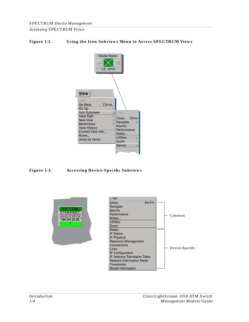
Icons and labels that display information within an icon, provide access to SPECTRUM views. This is done using double-click zones (Figure 1-1) or Icon Subviews menus (Figure 1-2).
To access the Icon Subviews menu as shown in Figure 1-2, and Figure 1-3 do the following:
1. Highlight the icon.
2. From the View menu, select
Icon Subviews
or click the applicable mouse button (middle or right). Refer to the
Operator’s Reference
for information on configuring your mouse.
9032352 E1 Introduction1-3
SPECTRUM Device Management
Accessing SPECTRUM Views
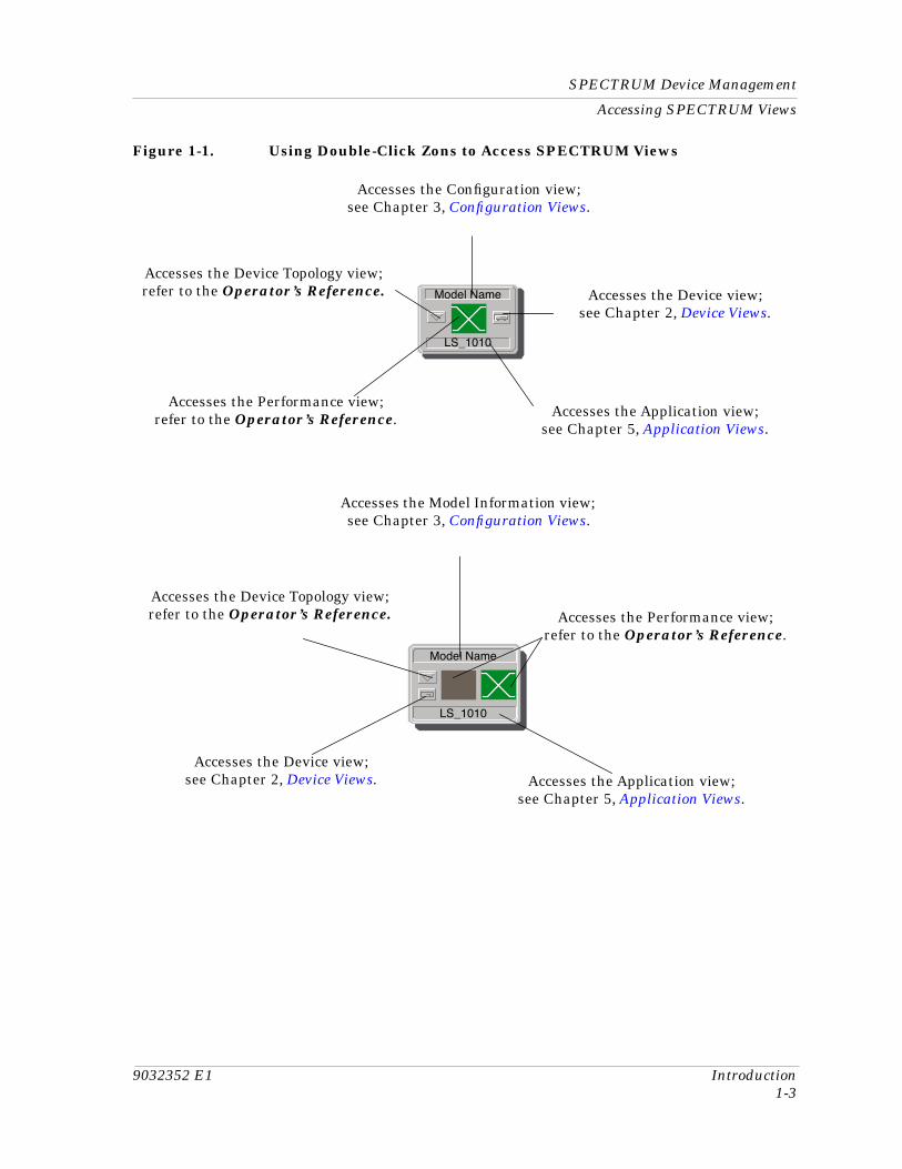
Figure 1-1. Using Double-Click Zons to Access SPECTRUM Views
Accesses the Model Information view; see Chapter 3, Configuration Views.
Accesses the Application view; see Chapter 5, Application Views.
Accesses the Configuration view; see Chapter 3, Configuration Views.
Accesses the Application view; see Chapter 5, Application Views.
Accesses the Performance view; refer to the Operator’s Reference.
Model Name
LS_1010
Model Name
LS_1010
Accesses the Device view; see Chapter 2, Device Views.
Accesses the Device Topology view; refer to the Operator’s Reference. Accesses the Device view;
see Chapter 2, Device Views.
Accesses the Performance view; refer to the Operator’s Reference.
Accesses the Device Topology view; refer to the Operator’s Reference.
SPECTRUM Device ManagementAccessing SPECTRUM Views
Introduction Cisco LightStream 1010 ATM Switch1-4 Management Module Guide
Figure 1-2. Using the Icon Subviews Menu to Access SPECTRUM Views
Figure 1-3. Accessing Device-Specific Subviews
Go Back Ctrl+bGo UpIcon SubviewsView PathNew ViewBookmarksView HistoryCurrent View Info...Notes...Jump by name...
Close Ctrl+cNavigateAlarmsPerformanceNotes...UtilitiesZoomDevice
View
Model Name
LS_1010
Device-Specific
Common
Close Alt+F4NavigateAlarmsPerformanceNotes...UtilitiesZoomDetailIF StatusIF PhysicalResource ManagementConnectionsLinksIF ConÞgurationIF Address Translation TableNetwork Information PanelThresholdsModel Information
13 ONETHERNET0:01D:17:2F:CA
1134.141.27.20
9032352 E1 Introduction1-5
Table Views
Accessing SPECTRUM Views
Table ViewsWithin many of SPECTRUM’s views, you will find tables containing information that you can configure. These tables can be sorted, searched, and updated using the buttons contained within these views. These buttons are defined below. In addition, double-clicking any entry within these tables will open another view which contains identical information with the exception that this data pertains only to the entry selected.
Sorts the table columns by selecting a table column heading and then clicking the sort button. This only works once and there is no undo
Searches for a particular entry in the table.
Updates the table with the latest configuration information.
Sort
Find
Update

Table ViewsAccessing SPECTRUM Views
Introduction Cisco LightStream 1010 ATM Switch1-6 Management Module Guide
9032352 E12-1
Chapter 2
Device Views
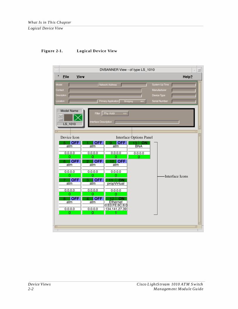
What Is in This ChapterThis chapter provides a description of the Device views for the Cisco LightStream 1010 ATM Switch Management Module. The Device view allows you to display a logical representation of the switch.
Logical Device View
The Logical Device view is a representation of the device configuration. If the configuration of the device changes during the polling cycle, SPECTRUM automatically updates the view. Figure 2-1 shows the Logical Device view.
What Is in This ChapterLogical Device View
Device Views Cisco LightStream 1010 ATM Switch2-2 Management Module Guide
Figure 2-1. Logical Device View
* File View Help?
Filter
Interface Description
Phy Addr
Model
Contact
Description
Location
Network Address System Up Time
Manufacturer
Device Type
Serial NumberPrimary Application
Interface Options PanelDevice Icon
Interface Icons
1atm
0
Bridging
0.0.0.0
Model Name
LS_1010
OFF
2atm
00.0.0.0
OFF
3atm
00.0.0.0
OFF
4atm
00.0.0.0
OFF
5atm
00.0.0.0
OFF
6atm
00.0.0.0
OFF
7atm
00.0.0.0
OFF
8atm
00.0.0.0
OFF
9atm
00.0.0.0
OFF
11propVirtual
00.0.0.0
ON
10atm
00.0.0.0
OFF
12Ethernet
1134.141.27.39
ON
13BNA
00.0.0.0
ON
0:E0:FE:6C:6:0
DVBANNER View - of type LS_1010
9032352 E1 Device Views2-3
What Is in This Chapter
Logical Device Detail
Logical Device Detail
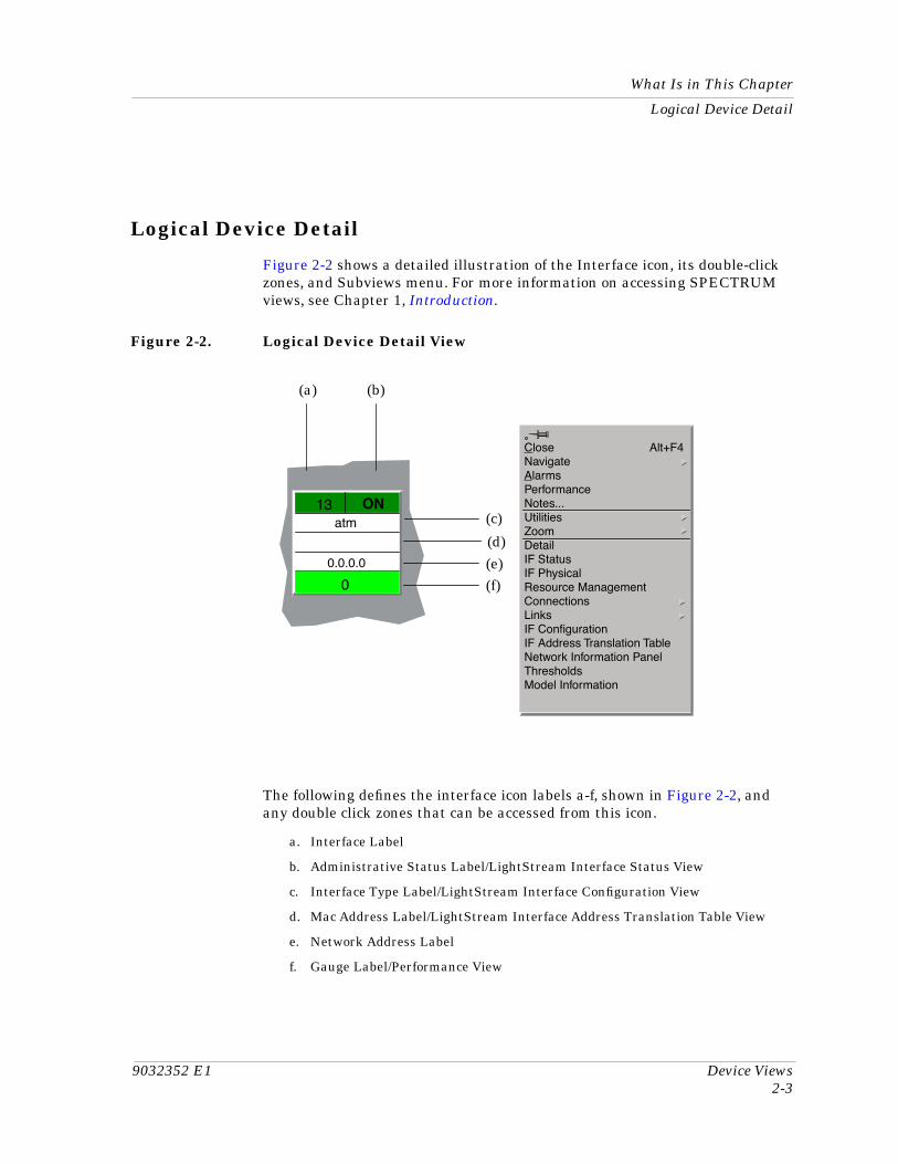
Figure 2-2 shows a detailed illustration of the Interface icon, its double-click zones, and Subviews menu. For more information on accessing SPECTRUM views, see Chapter 1, Introduction.
Figure 2-2. Logical Device Detail View
The following defines the interface icon labels a-f, shown in Figure 2-2, and any double click zones that can be accessed from this icon.
a. Interface Label
b. Administrative Status Label/LightStream Interface Status View
c. Interface Type Label/LightStream Interface Configuration View
d. Mac Address Label/LightStream Interface Address Translation Table View
e. Network Address Label
f. Gauge Label/Performance View
Close Alt+F4NavigateAlarmsPerformanceNotes...UtilitiesZoomDetailIF StatusIF PhysicalResource ManagementConnectionsLinksIF ConÞgurationIF Address Translation TableNetwork Information PanelThresholdsModel Information
13atm
0
0.0.0.0
ON(c)
(e)(f)
(a) (b)
(d)
What Is in This ChapterLogical Device Detail
Device Views Cisco LightStream 1010 ATM Switch2-4 Management Module Guide
Interface Label
This label displays the interface (port) number.
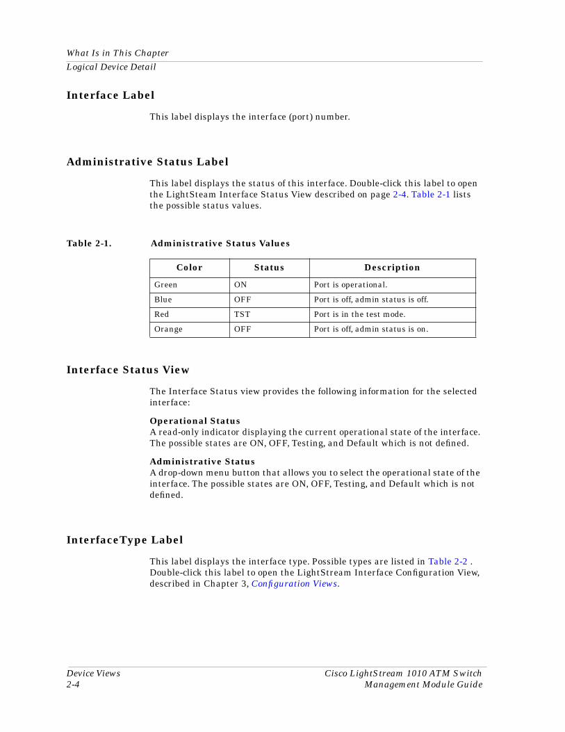
Administrative Status Label
This label displays the status of this interface. Double-click this label to open the LightSteam Interface Status View described on page 2-4. Table 2-1 lists the possible status values.
Interface Status View
The Interface Status view provides the following information for the selected interface:
Operational StatusA read-only indicator displaying the current operational state of the interface. The possible states are ON, OFF, Testing, and Default which is not defined.
Administrative StatusA drop-down menu button that allows you to select the operational state of the interface. The possible states are ON, OFF, Testing, and Default which is not defined.
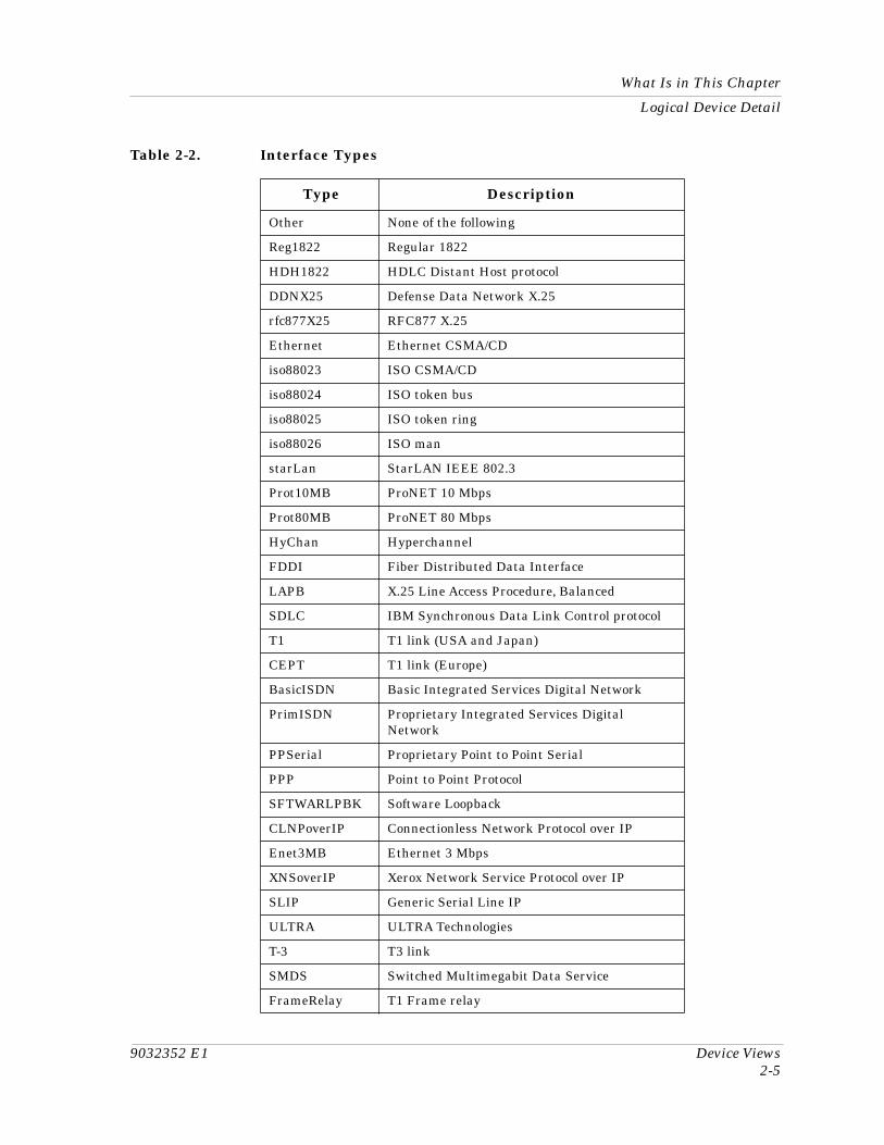
InterfaceType Label
This label displays the interface type. Possible types are listed in Table 2-2 . Double-click this label to open the LightStream Interface Configuration View, described in Chapter 3, Configuration Views.
Table 2-1. Administrative Status Values
Color Status Description
Green ON Port is operational.
Blue OFF Port is off, admin status is off.
Red TST Port is in the test mode.
Orange OFF Port is off, admin status is on.
9032352 E1 Device Views2-5
What Is in This Chapter
Logical Device Detail
Table 2-2. Interface Types
Type Description
Other None of the following
Reg1822 Regular 1822
HDH1822 HDLC Distant Host protocol
DDNX25 Defense Data Network X.25
rfc877X25 RFC877 X.25
Ethernet Ethernet CSMA/CD
iso88023 ISO CSMA/CD
iso88024 ISO token bus
iso88025 ISO token ring
iso88026 ISO man
starLan StarLAN IEEE 802.3
Prot10MB ProNET 10 Mbps
Prot80MB ProNET 80 Mbps
HyChan Hyperchannel
FDDI Fiber Distributed Data Interface
LAPB X.25 Line Access Procedure, Balanced
SDLC IBM Synchronous Data Link Control protocol
T1 T1 link (USA and Japan)
CEPT T1 link (Europe)
BasicISDN Basic Integrated Services Digital Network
PrimISDN Proprietary Integrated Services Digital Network
PPSerial Proprietary Point to Point Serial
PPP Point to Point Protocol
SFTWARLPBK Software Loopback
CLNPoverIP Connectionless Network Protocol over IP
Enet3MB Ethernet 3 Mbps
XNSoverIP Xerox Network Service Protocol over IP
SLIP Generic Serial Line IP
ULTRA ULTRA Technologies
T-3 T3 link
SMDS Switched Multimegabit Data Service
FrameRelay T1 Frame relay
What Is in This ChapterLogical Device Detail
Device Views Cisco LightStream 1010 ATM Switch2-6 Management Module Guide
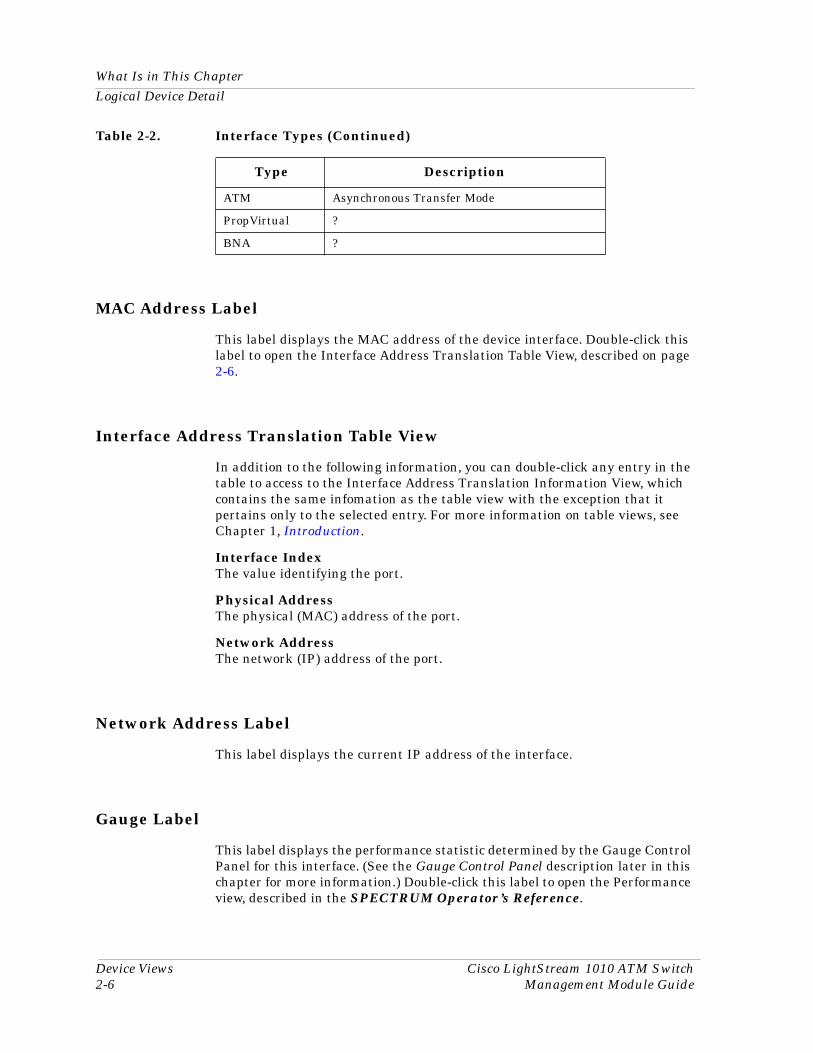
MAC Address Label
This label displays the MAC address of the device interface. Double-click this label to open the Interface Address Translation Table View, described on page 2-6.
Interface Address Translation Table View
In addition to the following information, you can double-click any entry in the table to access to the Interface Address Translation Information View, which contains the same infomation as the table view with the exception that it pertains only to the selected entry. For more information on table views, see Chapter 1, Introduction.
Interface IndexThe value identifying the port.
Physical AddressThe physical (MAC) address of the port.
Network AddressThe network (IP) address of the port.
Network Address Label
This label displays the current IP address of the interface.
Gauge Label
This label displays the performance statistic determined by the Gauge Control Panel for this interface. (See the Gauge Control Panel description later in this chapter for more information.) Double-click this label to open the Performance view, described in the SPECTRUM Operator’s Reference.
ATM Asynchronous Transfer Mode
PropVirtual ?
BNA ?
Table 2-2. Interface Types (Continued)
Type Description
9032352 E1 Device Views2-7
What Is in This Chapter
Logical Device Detail
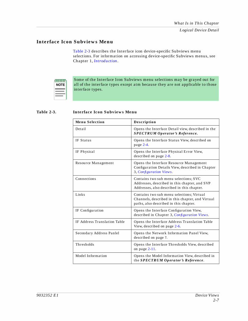
Interface Icon Subviews Menu
Table 2-3 describes the Interface icon device-specific Subviews menu selections. For information on accessing device-specific Subviews menus, see Chapter 1, Introduction.
NOTE
Some of the Interface Icon Subviews menu selections may be grayed out for all of the interface types except atm because they are not applicable to those interface types.
Table 2-3. Interface Icon Subviews Menu
Menu Selection Description
Detail Opens the Interface Detail view, described in the SPECTRUM Operator’s Reference.
IF Status Opens the Interface Status View, described on page 2-4.
IF Physical Opens the Interface Physical Error View, described on page 2-8.
Resource Management Opens the Interface Resource Management Configuration Details View, described in Chapter 3, Configuration Views.
Connections Contains two sub menu selections; SVC Addresses, described in this chapter, and SVP Addresses, also described in this chapter.
Links Contains two sub menu selections; Virtual Channels, described in this chapter, and Virtual paths, also described in this chapter.
IF Configuration Opens the Interface Configuration View, described in Chapter 3, Configuration Views.
IF Address Translation Table Opens the Interface Address Translation Table View, described on page 2-6.
Secondary Address Panlel Opens the Network Information Panel View, described on page ?.
Thresholds Opens the Interface Thresholds View, described on page 2-11.
Model Information Opens the Model Information View, described in the SPECTRUM Operator’s Reference.
What Is in This ChapterInterface Icon Subviews Menu Selections
Device Views Cisco LightStream 1010 ATM Switch2-8 Management Module Guide
Interface Icon Subviews Menu Selections
Interface Physical Error View
The Interface Physical Error View provides the following error information on a specific interface:
If IndexThe index number identifying the port to which it is attached.
StatusThe current staus of the interface. The value of this object is only valid when the interface’s Administrative Status is set to “up” . Possible values are los, lof, loc, ais, yelowLine, yellowPath, lop, idle, yellowAlarm, plcpLOF, plcpYellow, maFERF, pathAis, and ocd.
Plcp Bip ViolationsThe number of Physical Layer Convergence Protocol (PLCP) BIP violations on the physical interface. This object is only present for DS3/E3 interfaces.
Section Parity ErrorsThe number of section parity errors on the physical interface.This object is only present for SONET interfaces.
LCV ErrorsThe number of Line Code Violation (LCV) errors on the physical interface. This object is only present for DS3/E3 interfaces.
C Bit Parity ErrorsThe number of C-bit parity violations on the physical interface. This object is only present for DS3/E3 interfaces.
Path Parity ErrorsThe number of B3 (BIP) errors on the physical interface. This object is only present for SONET interfaces.
P Bit Parity ErrorsThe number of P-bit parity violations on the physical interface. This object is only present for DS3/E3 interfaces.
Connections
This Subview menu selection contains two sub-selections; SVC Addresses and SVP Adddresses.
9032352 E1 Device Views2-9
What Is in This Chapter
Interface Icon Subviews Menu Selections
SVC Addresses
The Switched Virtual Channel (SVC) Address Table view provides the following information:
IF IndexThe index number identifying the interface to which it is attached.
SVC AddressesThe SVC address. This depends on the direction the interface is in. Possible values are: p2pcalling (point to point calling), p2pcalled (point to point called), p2mproot (point to multi-point root) , and p2mpleaf (point to multi-point leaf).
VPI ValueThe SVC’s Virtual Path Identifier (VPI) value, on this interface.
VCI ValueThe SVC’s Virtual Channel Identifier (VCI) value, on this interface.
SVC DirectionThis value indicates whether the selected Virtual Channel Link (VCL) is the calling side, the side that has been called, the root side or the leaf for this address. Possible values are listed in Table 2-4.
SVP Addresses
The Switched Virtual Path (SVP) Address Table view, provides the following information:
SVP AddressThe address of the switched virtual path, depending upon whether the paths direction is: p2pCallingSide, p2pCalledSide, p2mpRoot or p2mpLeaf.
SVP’s VPIThe Switched Virtual Path’s (SVP) VPI value on this interface.
SVP DirectionThis value indicates whether the SVP is on the calling side, the called side, the root side or the leaf side. Table 2-4 lists the possible values.
Table 2-4. SVC & SVP Direction Values
Value Description
p2pCallingSide Point to point calling side.
p2pCalledSide Point to point called side.
What Is in This ChapterInterface Icon Subviews Menu Selections
Device Views Cisco LightStream 1010 ATM Switch2-10 Management Module Guide
Links
This subview menu selection contains two sub-selections; Virtual Channels and Virtual Paths.
Virtual Channels
Opens the IF Virtual Channel Link Table view which provides the following information on the switch’s VCLs. In addition, double-clicking any entry in this table will open the ATM IF Virtual Channel Link View. For more information on table views, see Chapter 1, Introduction.
VPIThe SVC’s VPI value on this interface.
VCIThe SVC’s VCI value on this interface.
Cast TypeThe VCL cast type, its possible values are: point to point, point to multi-point root, and point to multi-point leaf.
Span TypeThe VCL span types which can be either a transit connection or a terminating one. If it is a transit connection, then it is passed on, if it is a terminating connection, then it ends there.
Config TypeThe VCL configuration types. Possible values are: permanent, switch, soft, and other.
In CellsThe total number of cells received on the selected VCL.
Out CellsThe total number of cells transmitted on the selected VCL.
p2mpRoot Point to multi-point root.
p2mpLeaf Point to multi-point leaf.
Table 2-4. SVC & SVP Direction Values
Value Description
9032352 E1 Device Views2-11
What Is in This Chapter
Gauge Control Panel
Virtual Paths
Opens the IF Virtual Path Link Table view which contains the same information as the IF Virtual Channel Link Table view described on page 2-10.
Interface Threshold View
The Interface Threshold View provides the following information:
Load ThresholdThe ON and OFF values are set to determine the point at which a load alarm will be turned on or off.
Packet Rate ThresholdThe ON and OFF values are set to determine the point at which a packet transmission alarm will be turned on or off.
Error Rate ThresholdThe ON and OFF values are set to determine the point at which an error alarm will be turned on or off.
% Discarded ThresholdThe ON and OFF values are set to determine the point at which a discarded threshold alarm will be turned on or off.
Gauge Control Panel
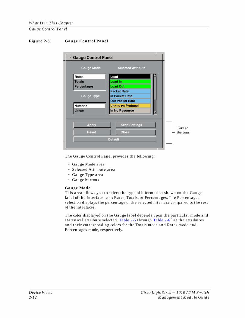
This view (Figure 2-3) allows you to change the type of statistical information displayed on the Gauge label of the Interface icon. To access the Gauge Control Panel view, double-click the background of the Interface Options panel within the main banner, or:
1. Highlight the Interface Options panel.
2. From the View menu, select Icon Subviews -> Gauge Control Panel.
What Is in This ChapterGauge Control Panel
Device Views Cisco LightStream 1010 ATM Switch2-12 Management Module Guide
Figure 2-3. Gauge Control Panel
The Gauge Control Panel provides the following:
• Gauge Mode area• Selected Attribute area• Gauge Type area• Gauge buttons
Gauge ModeThis area allows you to select the type of information shown on the Gauge label of the Interface icon: Rates, Totals, or Percentages. The Percentages selection displays the percentage of the selected interface compared to the rest of the interfaces.
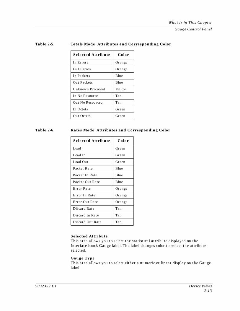
The color displayed on the Gauge label depends upon the particular mode and statistical attribute selected. Table 2-5 through Table 2-6 list the attributes and their corresponding colors for the Totals mode and Rates mode and Percentages mode, respectively.
Gauge Buttons
Gauge Mode Selected Attribute
Rates Load
Totals Load In
Percentages Load Out
Packet Rate
Gauge Type In Packet Rate
Out Packet Rate
Numeric Unknown Protocol
Linear In No Resource
Apply Keep Settings
Reset Close
Default
Gauge Control Panel
Rates
Numeric
9032352 E1 Device Views2-13
What Is in This Chapter
Gauge Control Panel
Selected AttributeThis area allows you to select the statistical attribute displayed on the Interface icon’s Gauge label. The label changes color to reflect the attribute selected.
Gauge TypeThis area allows you to select either a numeric or linear display on the Gauge label.
Table 2-5. Totals Mode: Attributes and Corresponding Color
Selected Attribute Color
In Errors Orange
Out Errors Orange
In Packets Blue
Out Packets Blue
Unknown Protocoal Yellow
In No Resource Tan
Out No Resourceq Tan
In Octets Green
Out Octets Green
Table 2-6. Rates Mode: Attributes and Corresponding Color
Selected Attribute Color
Load Green
Load In Green
Load Out Green
Packet Rate Blue
Packet In Rate Blue
Packet Out Rate Blue
Error Rate Orange
Error In Rate Orange
Error Out Rate Orange
Discard Rate Tan
Discard In Rate Tan
Discard Out Rate Tan
What Is in This ChapterGauge Control Panel
Device Views Cisco LightStream 1010 ATM Switch2-14 Management Module Guide
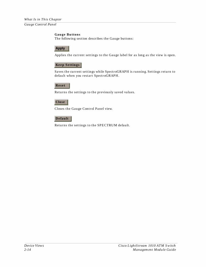
Gauge ButtonsThe following section describes the Gauge buttons:
Applies the current settings to the Gauge label for as long as the view is open.
Saves the current settings while SpectroGRAPH is running. Settings return to default when you restart SpectroGRAPH.
Returns the settings to the previously saved values.
Closes the Gauge Control Panel view.
Returns the settings to the SPECTRUM default.
Apply
Keep Settings
Reset
Close
Default
9032352 E13-1
Chapter 3
Configuration Views
What Is in This ChapterThis chapter describes the Configuration views available for the Cisco LightStream 1010 ATM Switch. These views display network configuration and operating information for the device and its interfaces.
The following Configuration views are available for this device:
• Interface Configuration• Device Configuration• Translation Table Configuration View• Switch Resource Management Configuration• Switch Resource Management Configuration Details View• Switch Application Interface Configuration View
Interface Configuration View
Configuration Views Cisco LightStream 1010 ATM Switch3-2 Management Module Guide
Interface Configuration View This view contains more detailed network configuration information for the device interface. To access this view:
1. Highlight the device Icon within the Logical Device view.
2. Select IF Configuration from the Icon Subviews menu.
This view provides the following information:
IF IndexDisplays the index which is attached to the selected interface.
Total ConnectionsThe total number of existing connections at this interface.
ILMI ConfigEnable/Disable Interim Local Management Interface (ILMI) configuration on this interface. The configuration takes effect on the next interface restart.
ILMI Auto ConfigEnable/Disable ILMI link and interface type determination. The configuration takes effect on the next interface restart
ILMI Address RegEnable/Disable ILMI address registration on this interface. This configuration takes effect on the next interface restart.
ILMI Keep AliveThe amount of time, in seconds, that should elapse between successive ILMI keepalive messages sent on this interface. A value of 0 disables this function.
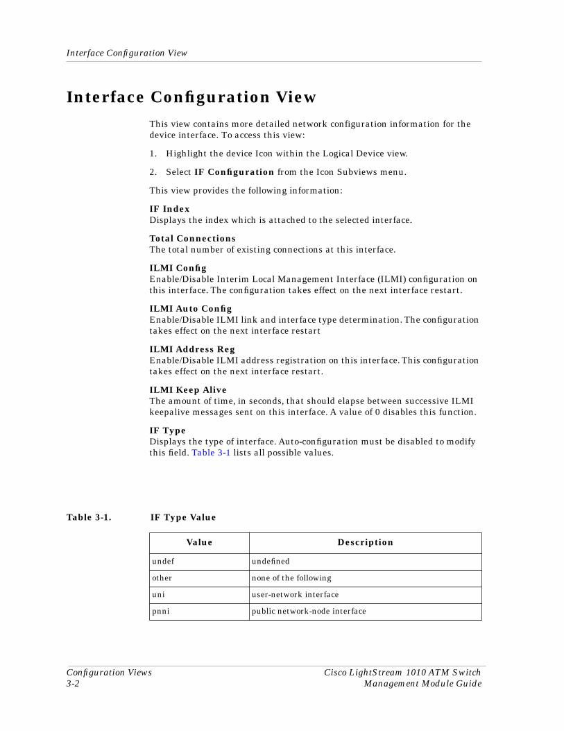
IF TypeDisplays the type of interface. Auto-configuration must be disabled to modify this field. Table 3-1 lists all possible values.
Table 3-1. IF Type Value
Value Description
undef undefined
other none of the following
uni user-network interface
pnni public network-node interface
9032352 E1 Configuration Views3-3
Interface Configuration View
UNI TypeThe type of User to Network Interface (UNI) this interface is using. Its value can be either public or private.
SideThe side of the network user interface which is either a user or network side. Not Applicable indicates that it is other than uni or iisp.
Port TypeThe type of physical layer medium on the port. Possible values are cpu, ethernet, oc3Utp, oc3SingModeFiber, oc3MultiModeFiber, oc12SingModeFiber, ds, e3, and other.
Received CellsThe number of cells received on this interface.
Received LedThe received LED color for this port. Possible values are: off, steadyGreen, steadyYellow, steadyRed, flashGreen, flashYellow, and flashRed.
Xmited CellsThe number of cells transmitted on this interface.
Xmit LedThe transmitted LED color for this port. Possible values are: off, steadyGreen, steadyYellow, steadyRed, flashGreen, flashYellow, and flashRed.
Active SVPsThe number of active Switched Virtual Paths (SVPs) at this interface.
Active SVCsThe number of active Switched Virtual Channels (SVCs) at this interface.
PVPsThe number of Permanent Virtual Paths (PVPs) at this interface.
PVCsThe number of Permanent Virtual Channels (PVCs) at this interface.
Configured VPsThe number of configured Virtual Paths at this interface.
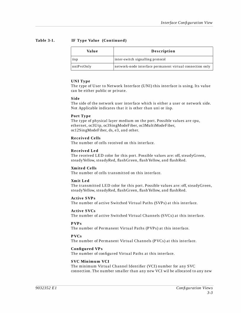
SVC Minimum VCIThe minimum Virtual Channel Identifier (VCI) number for any SVC connection. The number smaller than any new VCI wil be allocated to any new
iisp inter-switch signalling protocol
nniPvcOnly network-node interface permanent virtual connection only
Table 3-1. IF Type Value (Continued)
Value Description
Device Configuration View
Configuration Views Cisco LightStream 1010 ATM Switch3-4 Management Module Guide
PVC. This applies to every Virtual Path Identifier (VPI) number of the physical interface and every logical port.
VC Dest AddressThe twenty byte ATM address of the destination ATM interface for soft ATM PVC/PVP.
Device Configuration View This view contains more detailed network configuration information for the device. To access this view:
1. Highlight the Device Icon within the Logical Device view.
2. Select Configuration from the Icon Subviews menu.
This view provides the following information:
Device NameThe name of the device.
Contact StatusIndicates whether a connection with this device has been established.
Number of InterfacesIndicates the number of interfaces connected to this device.
Router RedundancyIndicates whether this device has router redundancy capabilities. This will either be False or True.
This button opens the Interface Address Translation Table View, described in Chapter 2, Device Views.
This button allows you to reconfigure the table. Upon completion a pop-up window appears stating that that the action was successful ?
Interface Configuration TableIn addition to providing the following information, double-clicking any entry in the table will open the LightStream Interface Configuration Information View. For more information on table views, see Chapter 1, Introduction.
IndexIndicates the index number to which the interface is attached.
IF Address Translation
ReconÞgure
9032352 E1 Configuration Views3-5
Switch Resource Management Configuration View
Default QOS Objective
DescriptionDisplays a description of the interface and its location within the switch.
TypeIndicates the type of interface attached to the device. Possible types are listed in Table 2-2.
BandwidthDisplays the current bandwidth value being used by the interface.
Physical AddressThe physical ( MAC) address for the active Ethernet port only.
Oper StatusDisplays the current operational status of the interface.
Admin StatusDisplays the current Administrative status of the interface, either on or off.
Last ChangeDisplays when the last change was made to the interface.
Packet SizeDisplays the size of the packet on the interface.
Switch Resource Management Configuration View
This view contains more detailed network configuration information for the device. To access this view:
1. Highlight the Switching Application icon within the Application view.
2. Select Resource Management from the Icon Subviews menu.
This view is divided into two tables that provide the following information:
Default QOS Objective
This table contains resource management configuration information for default Quality of Service (QoS) objective values used when a signalling request is received on a UNI interface. The following fields are cross-referenced by the QoS categories CBR, VBR RT, and VBR NRT.
QOS MaxThe default maximum Cell Transfer Delay (CTD) for the service category. It applies only to Constant Bit Rate (CBR) and Variable Bit Rate-Real Time (VBR-RT) service categories. Specifying a value of 16777215 signifies that this
Switch Resource Management Configuration ViewQueued Cells
Configuration Views Cisco LightStream 1010 ATM Switch3-6 Management Module Guide
parameter should not be checked during connection setup. The units are measuered in microseconds.
Peak to Peak CDVThe default peak-to-peak Cell Delay Variation (CDV) for the service category. It applies only to cbr and vbr-rt service categories. Specifying a value of 16777215 signifies that this parameter should not be checked during connection setup. The units are measuered in microseconds.
QOS CLRThe default QOS Cell Loss Ratio (CLR) for the service category Specifying a value of 0 signifies that this parameter should not be checked during connection setup. The units of this object are negative powers of ten.
Queued Cells
This table contains Resource Management information on the cells in the output queues of a shared-memory switch. Rows are indexed by priority and cross-referenced by Cell Limit and Cell Count.
PriorityThe cell priority. Possible values are p1, p2, p3, and p4.
Cell LimitConfigured limit on the number of cells on all output queues of the switch at any time of a particular priority.
Cell CountThe number of all cells on all output queues of the switch at any time of a particular priority.
In addition to the tables, this view also provides the following information.
Over Subscription FactorThe Over Subscription Factor (OSF) is used on switch startup/OIR to determine the maximum sizes of VBR-NRT and ABR/UBR queues. In general, the larger the value of the OSF specified, the larger the queues are made at startup.
SCR Margin FactorThe Sustained Cell Rate Margin Factor (SCRMF) is used in Conection Admission Control (CAC) of VBR connections to vary the weight given to the difference between Sustained Cell Rate (SCR) and Peak Cell Rate (PCR) specified in the traffic contract.
ABR Congestion NotifyThe ABR congestion notification object determines the type of congestion notification used on ABR connections in the switch. This notification can be done either via relative-rate or Explicit Forward Congestion Indication marking in ATM cells or both. Possible values are: Relative Rate, EFCI, and EFCI and Rel Rate.
9032352 E1 Configuration Views3-7
Switch Resource Management Configuration Details View
Switch Resource Management Configuration Details View
This view contains more detailed network configuration information for the device. To access this view:
1. Highlight the Device Icon within the Logical Device view.
2. Select Resource Management from the Icon Subviews menu.
This view provides the following information:
IF IndexThe unique value assigned to the interface for identification purposes.
Link DistanceThe link distance defined for the interface, expressed in kilometers.
Best Effort LimitThe limit on the number of Best Effort connections that can be established on this interface. A value of 4294967295 disables this field.
Out Pacing:
ForceMust be set to forceChange, only if changing the pacing rate would reduce the port rate below the value currently alocated to Guaranteed Services Categories (CBR/VBR) for the output flow.
Rate RequestedThis field reflects an explicit configuration of the state of pacing, expressed in kilobits per second, for this interface. If the value of this field is zero, pacing is disabled.
Rate InstalledThe output pacing value, in kilobits per second. This object is not defined for logical port ATM interfaces.
Traffic FlowThis field contains a button labeled Direction and when clicked on it opens the LightStream Interface Resource Management Traffic Flow Direction View described below.
Service CategoryThis field contains two buttons, State and Statistics. Clicking on State opens the Interface Resource Management State Information view, described in this chapter. Clicking on Statistics opens the Interface Resource Management Statistics Information view, described in this chapter
Output QueuesThis field contains two buttons, Configuration and Thresholds. Clicking on Configuration opens the Interface Resource Management Output Queue Configuration View, described in this chapter, Clicking on Thresholds opens

Switch Resource Management Configuration Details ViewInterface Resource Management Traffic Flow Direction View
Configuration Views Cisco LightStream 1010 ATM Switch3-8 Management Module Guide
the Interface Resource Management Thresholds View described in this chapter.
Interface Resource Management Traffic Flow Direction View
This view displays detailed information on the traffic flow direction of the ATM interface.
Max AggregateA configuration in the Controller Link Sharing (CLS) scheme which specifies the maximum aggregate Guaranteed Service (CBR or VBR) traffic that can be allocated in a traffic direction on an interface. It is expressed as a percentage of the maximum traffic direction's bandwidth (applies after output pacing, for example). This object interacts with MaxVbr (if specified) such that MaxVbr <= MaxAgg. This object interacts with MaxCbr (if specified) such that MaxCbr <= MaxAgg. This object interacts with MaxAbr (if specified) such that MaxAbr <= MaxAgg. This object interacts with MaxUbr (if specified) such that MaxUbr <= MaxAgg.If the object is set to -1, the object is considered to be unspecified. This object is not defined for logical port ATM interfaces.
Link Share Min CBRA Configuration in the Controller Link Sharing (CLS) scheme which specifies a minimum amount of CBR traffic that canbe reserved in a traffic direction on an interface. It is expressed as a percentage of the maximum traffic direction's bandwidth (applies after output pacing,for example). This object interacts with MinVbr, MinAbr, MinUbr (if specified) such that MinVbr + MinCbr + MinAbr + MinUbr <= 95%. This object interacts with MaxCbr (if specified) such that MinCbr < MaxCbr.If the object is set to -1, the object is considered to be unspecified. This object is not defined for logical port ATM interfaces.
Link Share Max CBRA Configuration in the Controller Link Sharing (CLS) scheme whci specifies the maximum CBR traffic that can be allocated in a traffic direction on an interface. It is expressed as a percentage of the maximum traffic direction's bandwidth (applies after output pacing, for example). This object interacts with MinCbr (if specified) such that MinCbr <= MaxCbr. This object interacts with MaxAgg (if specified) such that MaxCbr <= MaxAgg. (not defined for logical port ATM interfaces).
NOTE
A change to the value of these fields will affect subsequent connections, not the existing connection.
9032352 E1 Configuration Views3-9
Switch Resource Management Configuration Details View
Interface Resource Management Traffic Flow Direction View
Link Share Min VBRA Configuration in the Controller Link Sharing (CLS) scheme which specifies a minimum amount of VBR traffic that can be reserved in a traffic direction on an interface. It is expressed as a percentage of the maximum traffic direction's bandwidth (applies after output pacing, for example). This object interacts with MinCbr, MinAbr, and MinUbr (if specified), such that MinVbr + MinCbr + MinAbr + MinUbr <= 95%. This object interacts with MaxVbr (if specified) such that MinVbr <= MaxVbr. If the object is set to -1, the object is considered to be unspecified This object is not defined for logical port ATM interfaces.
Link Share Max VBRA configuration in the Controller Link Sharing (CLS) scheme which specifies the maximum VBR traffic that can be allocated in a traffic direction on an interface. It is expressed as a percentage of the maximum traffic direction's bandwidth (applies after output pacing, for example). This object interacts with MinVbr (if specified) such that MinVbr <= MaxVbr. This object also interacts with MaxAgg (if specified) such that MaxVbr <= MaxAgg. If the object is set to -1, the object is considered to be unspecified. This object is not defined for logical port ATM interfaces.
Max CBR PCRThis value specifies the maximum Peak Cell Rate (PCR) traffic parameter that can be specified for CBR connections in a traffic direction on an interface. It is specified in cells-per-second.
Max CBR ToleranceThis value specifies the maximum limit parameter, in cell-times, used in the GCRA algorithm for traffic policing that can be specified for CBR connections in a traffic direction on an interface..
Max VBR PCRThis value specifies the maximum PCR traffic parameter that can be specified for VBR connections in a traffic direction on an interface. It is specified in cells-per-second.
Max VBR SCRThis value specifies the maximum Sustained Cell Rate (SCR) traffic parameter that can be specified for VBR connections in a traffic direction on an interface. It is specified in cells-per-second.
NOTE
The following fields can be disabled by entering the value 4294967295.
Switch Resource Management Configuration Details ViewInterface Resource Management State Information View
Configuration Views Cisco LightStream 1010 ATM Switch3-10 Management Module Guide
Max VBR ToleranceThis value specifies the maximum limit parameter used in the Generic Cell Rate Algorithm (GCRA) for traffic policing that can be specified for VBR connections in a traffic direction on an interface. It is specified in cell-times.
Max ABR PCRThis value specifies the maximum PCR traffic parameter that can be specified for ABR connections in a traffic direction on an interface. It is specified in cells-per-second.
Max ABR ToleranceThis value specifies the maximum limit parameter used in the GCRA algorithm for traffic policing that can be specified for ABR connections in a traffic direction on an interface. It is specified in cell-times.
Max UBR PCRThis value specifies the maximum PCR traffic parameter that can be specified for UBR connections in a traffic direction on an interface. It is specified in cells-per-second.
Max UBR ToleranceThis value specifies the maximum limit parameter used in the GCRA for traffic policing that can be specified for UBR connections in a traffic direction on an interface. It is specified in cell-times.
Interface Resource Management State Information View
This view is a table implemented using integers. It provides the following information.
All of these fields are cross-referenced by Service Category. The categories are CBR, VBR RT, VBR NRT, ABR, and UBR.
Avail Cell Rate (RX)The available cell rate, in cells per second, for traffic received on the interface for this Service Category. This is the bandwidth available for connections.
Avail Cell Rate (TX)The available cell rate, in cells per second, for traffic transmitted on the interface for this Service Category. This is the bandwidth available to connections.
Alloc Cell Rate (RX)The allocateds cell rate, in cells per second, for traffic received on the interface for this Service Category. This is the bandwidth available for connections.
Alloc Cell Rate (TX)The allocated cell rate, in cells per second, for traffic transmitted on the interface for this Service Category. This is the bandwidth available to connections.
9032352 E1 Configuration Views3-11
Switch Resource Management Configuration Details View
Interface Resource Management Statistics Information View
# Signalled ConnsThe number of signalled connections (VC or VP) of this Service Category currently allocated on this interface.
# Permanent ConnsThe number of permanent connections (VC or VP) of this Service Category currently allocated on this interface.
Max Cell Trans. DelayThe Maximum Cell Transfer Delay estimated to be experienced by cells of connections transmitted on this interface for the Service Category.
Peak to Peak CDVThe default peak-to-peak Cell Delay Variation estimated to be experienced by cells of connections transmitted on this interface for the Service Category.
TX Cell Loss RatioThe Cell Loss Ratio estimated to be experienced by cells of connections transmitted on this interface for the Service Category.
Interface Resource Management Statistics Information View
This view is a table implemented using integers. It provides the following information.
All of these fields are cross-referenced by Service Category. The categories are CBR, VBR RT, VBR NRT, ABR, and UBR.
Total Alloc RequestsThe number of resource allocation requests for this interface.
SuccessfulThe number of successful resource allocation requests for this interface.
Failed (Trafic Params)The number of resource allocation requests which are considered to be in error due to an unsupported combination of traffic parameters.
Failed (Lack Bandwidth)The number of resource allocation requests which are considered to be in error due to a lack of bandwidth.
Failed (Cell Loss)The number of resource allocation requests which are considered to be in error due to exceeding cell loss criterion.
Failed (Delay)The number of resource allocation requests which are considered to be in error because they exceed cell loss criterion.

Switch Resource Management Configuration Details ViewInterface Resource Management Output Queue Configuration View
Configuration Views Cisco LightStream 1010 ATM Switch3-12 Management Module Guide
Failed (Cell Delay Var)The number of resource allocation requests which are considered to be in error because they exceed cell delay variation criterion.
Failed (BE Limit)The number of resource allocation requests which are considered to be in error because they exceed a limit on the number of best-effort connections.
Failed (Parm Limit)The number of resource allocation requests which are considered to be in error because they exceed cell delay variation criterion.
Failed (Other)The number of resource allocation requests which are considered to be in error for an unknown reason.
Interface Resource Management Output Queue Configuration View
This view contains the Output Queue Configuration Table, which provides the following information:
Service CatThe Service Category(s) sharing this output queue on the ATM interface. Possible bit positions are:
1: constant bit rate (CBR)
2: variable bit rate- real time (VBR-RT)
4: variable bit rate-non real time (VBR-NRT)
8: available bit rate (ABR)
16: unspecified bit rate (UBR)
24: not defined
Req. Max SizeThe configuration of the maximum number of cells that may occupy this queue. If the default value is 0 then the queue size is calculated by software.
Inst. Max SizeThe maximum number of cells that may occupy this queue. This value will be a multiple of 32.
Max Size ForceChanges the value of the Requested Maximum Size of a queue.
Cell CountCount of the number of cells in the output queue.
9032352 E1 Configuration Views3-13
Switch Application Interface Configuration View
Interface Resource Management Thresholds View
Interface Resource Management Thresholds View
This view contains the Interface Thresholds table which provides threshold values for the following service categories: CBR, VBR-RT, VBR-NRT, ABR, and UBR.
DiscardThe output queue Cell Loss Priority/EPD (CLP/PD) threshold for this Service Category on this ATM interface.
EFCIThe output queue Explicit Forward Congestion Indication (EFCI) marking threshold for this Service Category on this ATM interface.
Switch Application Interface Configuration View
This view contains more detailed network configuration information for the device. To access this view:
1. Highlight the Switching Application icon within the Applications view.
2. Select Interface Configuration from the Icon Subviews menu.
This view is broken into two tables that are detailed below:
ATM IF Configuration Table
This table provides the following information about the ATM interface configuration:
IF IndexThe unique value identifying the interface to which it is attached.
Max VPCsMaximum number of Virtual Path Connections (VPCs) supported per interface.
Max VCCsMaximum number of Virtual Channel Connections (VCCs) supported per interface.
Conf VPCsThe number of configured VPCs on the interface. Can range from 0-256.
Config VCCsThe number of configured VCCs on the interface.
Switch Application Interface Configuration ViewIF Configuration Table
Configuration Views Cisco LightStream 1010 ATM Switch3-14 Management Module Guide
Max VPI BitsMaximum number of Virtual Path Identifier bits (VPI bits) allowed on this interface
Max VCI BitsMaximum number of Virtual Channel Identifire bits (VCI bits) allowed on this interface.
ILMI VPIThe VPI value of the VCC suporting the ILMI at this ATM interface.
ILMI VCIThe VCI value of the VCC supporting the ILMI at this ATM interface.
Address TypeThe type of primary ATM Address configured for use on this ATM interface. Possible values are: private, nsape164, nativeE164, and other.
Admin AddressAn address assigned for administrative purposes.
Neighbor AddressThe IP Address of the neighbor system connected to the far end of this interface, to which a network management station can send SNMP messages in order to access network information concerning the operation of the neighbor system.
Neighbor IF NameThe interface name of the neighbor system connected to the far end of this interface.
IF Configuration Table
This table provides the following information about the LightStream interface configuration:
IF IndexThe value of this object identifies the interface for which the entry contains management information.
ConnectionsThe number of connections currently attached to the interface.
PVPsThe number of PVPs currently attached to the interface.
PVCsThe number of PVCs currently attached to the interface.
Active SVPsThe number of SVPs currently active on the interface.
9032352 E1 Configuration Views3-15
Switch Application Interface Configuration View
IF Configuration Table
Active SVCsThe number of SVCs currently active on the interface.
Xmit CellsThe number of cells transmitted on this interface.
Recv CellsThe number of cells received on this interface.

Switch Application Interface Configuration ViewIF Configuration Table
Configuration Views Cisco LightStream 1010 ATM Switch3-16 Management Module Guide
9032352 E14-1
Chapter 4
Event and Alarm Messages
What Is in This ChapterThis chapter lists the types of events and alarms generated by the Cisco LightStream band provides any probable cause messages corresponding to these alarms.
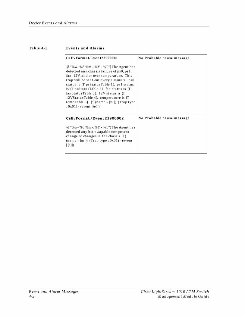
Device Events and AlarmsTable 4-1 lists the SPECTRUM database directory paths (in bold) and the messages displayed for the Event Log and Alarm Manager when applicable.
Device Events and Alarms
Event and Alarm Messages Cisco LightStream 1010 ATM Switch4-2 Management Module Guide
Table 4-1. Events and Alarms
CsEvFormat/Event23900001
{d "%w- %d %m-, %Y - %T"} The Agent has detected any chassis failure of ps0, ps1, fan, 12V, and or over temperature. This trap will be sent out every 1 minute. ps0 status is {T psStatusTable 1}. ps1 status is {T psStatusTable 2}. fan status is {T fanStatusTable 3}. 12V status is {T 12VStatusTable 4}. temperature is {T tempTable 5}. {t} (name - {m }). (Trap type : 0x01) - (event [{e}])
No Probable cause message.
CsEvFormat/Event23900002
{d "%w- %d %m-, %Y - %T"} The Agent has detected any hot-swapable component change or changes in the chassis. {t} (name - {m }). (Trap type : 0x01) - (event [{e}])
No Probable cause message.
9032352 E15-1
Chapter 5
Application Views
What Is in This ChapterThis chapter describes the Cisco LightStream 1010 ATM Switch’s device-specific applications which are listed below.
• LS_Switch_App• LS1010Chas_App• CiscoChasApp• CiscoIFApp• CiscoTSApp
Common ApplicationsThis device supports the following common applications described in the SPECTRUM Application View Reference:
• MIB-II (SNMP2_Agent)- ICMP (ICMP_App)- IP (IP2_App)- System (System2_App)- TCP (TCP2_App)- UDP (UDP2_App)
• RS-232 App (RFC1317App)
• This device also supports standard RMON (purchased separately) which is described in its management module guide.
Application ViewDevice Application View
Application Views Cisco LightStream 1010 ATM Switch5-2 Management Module Guide
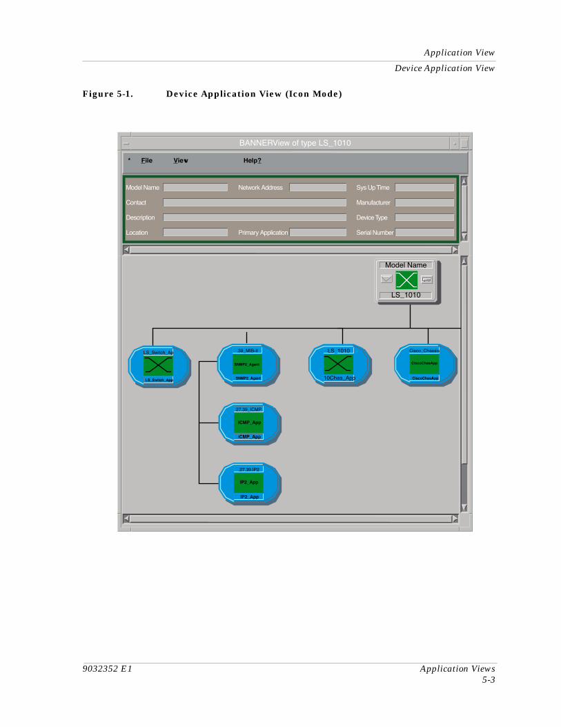
Application ViewThe Application view displays information on any application supported by the device. Each application appears as an icon in the Application view. Access application-specific Model Information Views, Performance Views, and Detail Views from these icons. Depending on the specific application, various additional views are also available and discussed in this section.
Device Application View
This view shows the common and device-specific applications supported by this device and provides access to application-specific information.
See Chapter 1, Introduction for information on Accessing SPECTRUM Views (1-2).
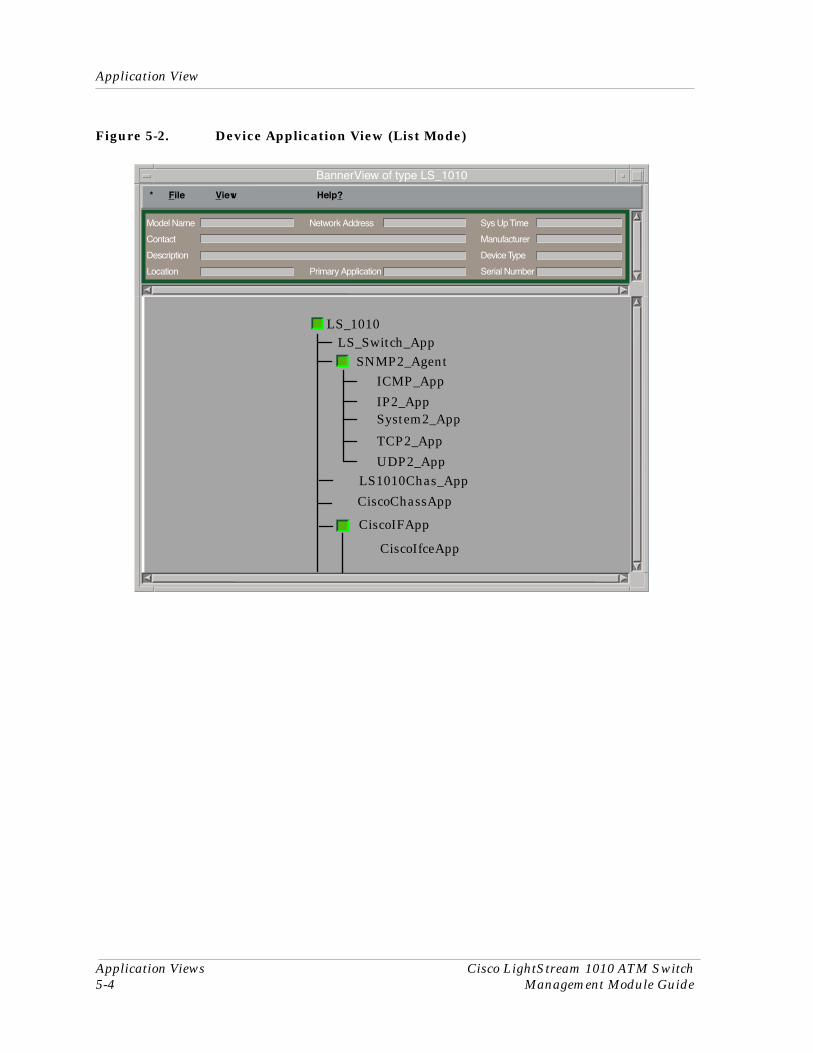
Figure 5-1 shows an example of an Application view in the Icon mode. Figure 5-2 shows an example of an Application view in the List mode.
To change the display mode, select View -> Mode -> List or Icon.
9032352 E1 Application Views5-3
Application View
Device Application View
Figure 5-1. Device Application View (Icon Mode)
BANNERView of type LS_1010
* File View Help?
Model Name
Contact
Description
Location
Network Address
Primary Application
Sys Up Time
Manufacturer
Device Type
Serial Number
LS_1010
10Chas_App
LS_Switch_Ap
LS_Switch_App
Model Name
LS_1010
Cisco_Chassis
CiscoChasApp
CiscoChasApp
.39_MIB-II
SNMP2_Agent
SNMP2_Agent
27.39_ICMP
ICMP_App
.27.39.IP2
IP2_App
ICMP_App
IP2_App
Application View
Application Views Cisco LightStream 1010 ATM Switch5-4 Management Module Guide
Figure 5-2. Device Application View (List Mode)
BannerView of type LS_1010
* File View Help?
Model Name
Contact
Description
Location
Network Address
Primary Application
Sys Up Time
Manufacturer
Device Type
Serial Number
LS_1010
SNMP2_AgentICMP_App
CiscoChassApp
LS_Switch_App
IP2_AppSystem2_App
TCP2_App
UDP2_App
CiscoIFApp
CiscoIfceApp
LS1010Chas_App
9032352 E1 Application Views5-5
Switching Application
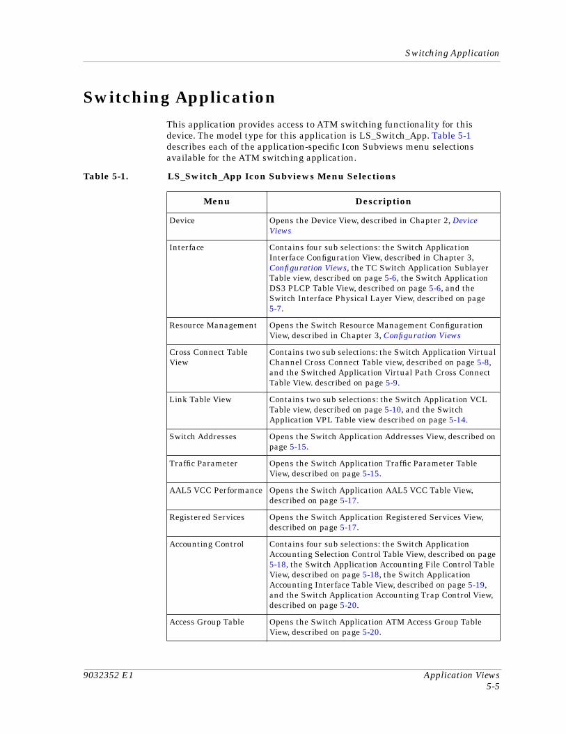
Switching ApplicationThis application provides access to ATM switching functionality for this device. The model type for this application is LS_Switch_App. Table 5-1 describes each of the application-specific Icon Subviews menu selections available for the ATM switching application.
Table 5-1. LS_Switch_App Icon Subviews Menu Selections
Menu Description
Device Opens the Device View, described in Chapter 2, Device Views
Interface Contains four sub selections: the Switch Application Interface Configuration View, described in Chapter 3, Configuration Views, the TC Switch Application Sublayer Table view, described on page 5-6, the Switch Application DS3 PLCP Table View, described on page 5-6, and the Switch Interface Physical Layer View, described on page 5-7.
Resource Management Opens the Switch Resource Management Configuration View, described in Chapter 3, Configuration Views
Cross Connect Table View
Contains two sub selections: the Switch Application Virtual Channel Cross Connect Table view, described on page 5-8, and the Switched Application Virtual Path Cross Connect Table View. described on page 5-9.
Link Table View Contains two sub selections: the Switch Application VCL Table view, described on page 5-10, and the Switch Application VPL Table view described on page 5-14.
Switch Addresses Opens the Switch Application Addresses View, described on page 5-15.
Traffic Parameter Opens the Switch Application Traffic Parameter Table View, described on page 5-15.
AAL5 VCC Performance Opens the Switch Application AAL5 VCC Table View, described on page 5-17.
Registered Services Opens the Switch Application Registered Services View, described on page 5-17.
Accounting Control Contains four sub selections: the Switch Application Accounting Selection Control Table View, described on page 5-18, the Switch Application Accounting File Control Table View, described on page 5-18, the Switch Application Accounting Interface Table View, described on page 5-19, and the Switch Application Accounting Trap Control View, described on page 5-20.
Access Group Table Opens the Switch Application ATM Access Group Table View, described on page 5-20.
Switching ApplicationInterface
Application Views Cisco LightStream 1010 ATM Switch5-6 Management Module Guide
Interface
This menu selection contains the following sub selections:
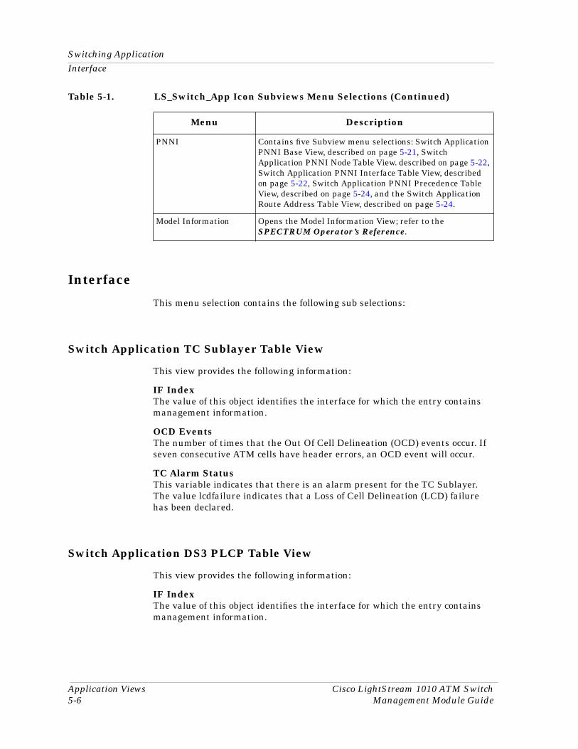
Switch Application TC Sublayer Table View
This view provides the following information:
IF IndexThe value of this object identifies the interface for which the entry contains management information.
OCD EventsThe number of times that the Out Of Cell Delineation (OCD) events occur. If seven consecutive ATM cells have header errors, an OCD event will occur.
TC Alarm StatusThis variable indicates that there is an alarm present for the TC Sublayer. The value lcdfailure indicates that a Loss of Cell Delineation (LCD) failure has been declared.
Switch Application DS3 PLCP Table View
This view provides the following information:
IF IndexThe value of this object identifies the interface for which the entry contains management information.
PNNI Contains five Subview menu selections: Switch Application PNNI Base View, described on page 5-21, Switch Application PNNI Node Table View. described on page 5-22, Switch Application PNNI Interface Table View, described on page 5-22, Switch Application PNNI Precedence Table View, described on page 5-24, and the Switch Application Route Address Table View, described on page 5-24.
Model Information Opens the Model Information View; refer to the SPECTRUM Operator’s Reference.
Table 5-1. LS_Switch_App Icon Subviews Menu Selections (Continued)
Menu Description
9032352 E1 Application Views5-7
Switching Application
Cross Connect Table View
SEFSsThe number of Digital Signal, Level 3 Physical Layer Convergence Protocol (DS3 PLCP) Severely Errored Framing Seconds (SEFSs). Each SEFS represents a one second interval which contains one or more SEF event.
Alarm StateThis variable indicates whether an alarm is present for the DS3 PLCP. Table 5-2 lists all possible values.
UASsThe counter associated with the number of Unavailable Seconds (UASs) encountered by the PLCP.
Switch Interface Physical Layer View
This view displays the IF Index of all interfaces currently attached to the device. Double-click any of the index entries to open the Interface Physical Error View, described in Chapter 2, Device Views.
Cross Connect Table View
This Icon Subviews menu selection contains the following sub selections which contain information about all virtual channel and virtual path cross connections, in addition these views contain a Row Status Procedure, which enables you to create a new connection or remove an existing one.
Row Status Procedure1. Click the Index button to select an index value. This will display aVC
Cross Connect Index dialog box which will provide an index.
2. Set Connection Information: Enter the requested information for this connection in the box labeled Connection Information, then press return.
a. Click OK in the Save Changes dialog box.
Table 5-2. DS3 PLCP Alarm Values
Value Description
noAlarm No alarm is currently present.
received FarEnd Alarm The DS3 PLCP has received an incoming yellow signal.
incomingLOF The DS3 PLCP has declared a Loss Of Frame failure condition.
Switching ApplicationCross Connect Table View
Application Views Cisco LightStream 1010 ATM Switch5-8 Management Module Guide
3. Click either the Create Connection button or the Remove Connection Button.
Switch Application Virtual Channel Cross Connect Table View
In addition to the following information, this table also provides double-click access to the Switch Application Virtual Channel Cross Connect View. For more information on table views, see Chapter 1, Introduction.
IndexA unique value used to identify this VC cross-connect.
Low IF
The value of this object is equal to the index value of the ATM interface port for this VC cross-connect.
Low VPIThe value of this object is equal to the VPI value at the ATM interface associated with this VC cross-connect.
Low VCIThe value of this object is equal to the VCI value at the ATM interface associated with this VC cross-connect.
High IFThe value of this object is equal to the index value for the ATM interface port for this VC cross-connect.
High VPIThe value of this object is equal to the VPI value at the ATM interface associated with the VC cross-connect High Index, defined above.
High VCIThe value of this object is equal to the VCI value at the ATM interface associated with the VC cross-connect High Index, defined above.
Admin StatusThe value of this object identifies the desired administrative status of the VC cross-connect. Possible states are up or down indicating that the traffic flow is enabled or disabled respectively.
Row StatusThe status of an entry in the table. Possibilities are active, notInService, notReady, createAndGo, createAndWait, and destroy
9032352 E1 Application Views5-9
Switching Application
Cross Connect Table View
Switch Application Virtual Channel Cross Connect View
This view contains the same information as the Switch Application Virtual Channel Cross Connect Table view, except it applies only to a single entry within the table. Also, this view contains the following information:
L2H Op StatusThis value identifies the current operational status of the VC cross-connection in one direction (i.e., from low to high).
H2L Op StatusThe value of this object identifies the current operational status of the VC cross-connection in one direction (i.e., from high to low).
L2H Last ChangeThis value is the same as the MIB II’s System Up Time at the time the VC cross-connect became active in a low to high direction.
H2L Last ChangeThis value is the same as the MIB II’s System Up Time at the time the VC cross-connect became active in a high to low direction.
Switch Application Virtual Path Cross Connect Table View
This view contains the following information:
IndexA unique value used to identify this VC cross-connect.
Low IndexThe value of this object is equal to the index value of the ATM interface port for this VC cross-connect.
Low VPIThe value of this object is equal to the VPI value at the ATM interface associated with this VC cross-connect.
High VPIThe value of this object is equal to the VPI value at the ATM interface associated with the VC cross-connect High IF, defined above.
Admin StatusThe value of this object identifies the desired administrative status of the VC cross-connect. Possible states are up or down indicating that the traffic flow is enabled or disabled respectively.
Row StatusThe status of an entry in the table. Possibilities are active, notInService, notReady, createAndGo, createAndWait, and destroy
Switching ApplicationLink Table View
Application Views Cisco LightStream 1010 ATM Switch5-10 Management Module Guide
Switch Application Virtual Path Cross Connect View
This view contains the same information as the Switch Application Virtual Path Cross Connect Table view, with the exception that it pertains only to the table entry selected. Also, this view contains the following information:
L2H Op StatusThis value identifies the current operational status of the VP cross-connection in one direction (i.e., from low to high).
H2L Op StatusThe value of this object identifies the current operational status of the VP cross-connection in one direction (i.e., from high to low).
L2H Last ChangeThis value is the same as the MIB II’s System Up Time at the time the VP cross-connect became active in a low to high direction.
H2L Last ChangeThis value is the same as the MIB II’s System Up Time at the time the VP cross-connect became active in a high to low direction.
Link Table View
This Icon Subviews menu selection contains the following sub selections which contain information about all virtual channel and path cross links, in addition these views contain a Row Status Procedure, which enables you to create a new link or remove an existing one.
Row Status Procedure1. Set Link Information: Enter the requested information for this connection
in the box labeled Link Information, then press return.
a. Click OK in the Save Changes dialog box.
2. Click either the Create Link button or the Remove Link Button.
Switch Application VCL Table View
In addition to the following information, this table also provides double-click access to the Switch Application Virtual Channel Link View, which contains the same information as the table view with the exception that it pertains only to the entry clicked on. For more information on table views, see Chapter 1, Introduction.
IFThe index number associated with this interface.
9032352 E1 Application Views5-11
Switching Application
Link Table View
VPIThe Virtual Channel’s VPI value on this interface.
VCIThe Virtual Channel’s VCI value on this interface.
Admin StatusThe value of this object identifies the desired administrative status of the VCL. Possible states are up or down indicating that the traffic flow is enabled or disabled respectively.
Oper StatusThe current operational status of the VCL. Possible states are up, down, and unknown.
Rx IndexThe row of the ATM Traffic Descriptor Table which applies to the receive direction of this VCL.
Xmit IndexThe row of the ATM Traffic Descriptor Table which applies to the transmit direction of this VCL.
AAL TypeThe type of ATM Adaption Layer (AAL) used on this VCL. Possible values are aal1, aal34, aal5, other, and unknown.
Xmit SizeThe maximum AAL5 Common Part Convergence Sublayer (CPCS) Service Data Unit (SDU) size, in octets, that is supported on the transmit direction of the VCL.
Rx SizeThe maximum AAL5 CPCS SDU size, in octets, that is supported on the receive direction of this VCL.
Encaps TypeThe type of data encapsulation used over the AAL5 SSCS layer. Possible types are vcMultiplexRoutedProtocol, vcMultiplexBridgedProtocol8023, vcMultiplexed BridgedProtocol8025, vcMultiplexedBridgedProtocol8026, vcMultiplexedLANemulation8023, vcMultiplexLANemulation8025, llcEncapsulation, multiprotocolFrameRelaySscs, other, and unknown.
Cross Connect IdThe connection identifier for a VCL which is cross-connected to another VCL on the same VCC.
Row StatusThe status of an entry in the table. Possibilities are active, notInService, notReady, createAndGo, createAndWait, and destroy.
Switching ApplicationLink Table View
Application Views Cisco LightStream 1010 ATM Switch5-12 Management Module Guide
Switch Application VCL View
To access this view, double click any entry within Switch Application VCL Table view. This view contains the same information as the table with the exception that the information pertains only to the selected entry. Also, this view contains the LightStream Table Extension button which is described below.
This button opens the Switch Application Interface Virtual Channel Link Table Extension View described below.
Switch Application Interface Virtual Channel Link Table Extension View
Num AttemptsNumber of retries made to install this soft virtual path connection.
Install TimeThe time when the VC counter began. This time is derived from System Up Time.
Slow Retry IntervalSoft Permanent Virtual Connection (SPVC) retry rate, in seconds.
OAM End LoopbackEnable end-to-end lopback on this virtual table.
OAM AIS EnableEnables the Alarm Indication Signal (AIS) function of the Operations, Administration and Maintenance (OAM) cell generation, if the connection goes down.
OAM RDI EnableEnables the Remote Defect Indication (RDI) of the OAM cell generation, if the connection goes down.
Cross IF IndexFor point to point connections, this number is the index for the cross-connected VPL for this VPL. For point to multipoint, this will be the root index VPL or this is the first leaf of a root VPL entry.
Cross VPIThis number specifies the VPI value of the VPL to which this VPL is connected.
Cross VCIThis number specifies the VCI value of the VPL to which this VPL is connected.
LightStream Table Extension
9032352 E1 Application Views5-13
Switching Application
Link Table View
In CellsThe total number of cells received on this VPL.
Out CellsThe total number of cell transmitted on this VPL.
AAL Encap ProtocolsProtocol for terminating the Virtual Channel, if the encapFlag value is set to aal5mux. Possible protocol values are: ip, xns, appletalk, clns, decnet, novell, apollo, vines, and other.
AAL Encap FlagEncapsulation type for terminating a Virtual Channel. Possible values are: aal5Snap, aal5Nlpid, aal5FrNlpid, aal5mux, aal34Smds, aalQsAal, aal5Ilmi, aal5Lane, and aal5Pnni.
AAL User VC TypeUser virtual circuit types. These only apply if the encapsulation type is aal5Lane. Possibilities are: boxConfigure, busForward, busSend, clientConfigure, clientData, clientDirect, clientDistribute, client Forward, clientSend, configure, serverConfigure, serverDirect, and serverDistribute.
Next Leaf IF IndexFor a point to point connection this value will be zero (i.e not used). For a point to multi-point connection this will be the next leaf VCL’s interface index on the multicast chain. This value will be zero, if this is the root VCL and if the value is zero for a leaf VCL. This also means that this is the last leaf.
Next Leaf VPIThis value applies only to point to multi-point connections where this will be the next leaf VCL’s VPI on the multicast chain.
Next Leaf VCIThis value applies only to point to multi-point connections where this will be the next leaf VCL’s VCI on the multicast chain.
LocationIndicates whether the Soft PVC is the called side or the calling side.
Last Release CauseNumber referencing a Cause Information Element which indicates the reason for the last software change.
Atm in Arp IntervalThe time interval, in minutes, to send Address Resolution Protocol (ARP) on a PVC for IP over ATM.
Cast TypeThe VCL cast type. Possible values are point to point, point to multi-point root, or leaf.
Span TypeThe VCL span type; either a transit one or a terminating one.
Switching ApplicationLink Table View
Application Views Cisco LightStream 1010 ATM Switch5-14 Management Module Guide
Config TypeThe configuration type of the VCL. Possible values are permanent, switch, soft, or other.
Remote AddrSoft PVC target address if this is the calling side of the connection else Soft PVC source address if this is the called side.
Remote VPISoft PVC target VPI in the calling side of the connection. This value is zero if this is the called side.
Remote VCI Soft PVC target VCI in the calling side of the connection. This value is zero if this is the called side.
Rx UPC ModeThis value represents the Usage Parameter Control (UPC) object. Possible values are: passing, tagging, dropping, or local shaping.
EPD EnableThis value represents the Early Packet Discard (EPD) operation and is either enabled or disabled.
Conn StateThe Connection State of this VCL, possible values are setup, release, not installed, down, and up.
Switch Application VPL Table View
This view contains the following virtual path link information:
IF The interface value associated with this entry.
Admin StatusThe value of this object identifies the desired administrative status of the VPL. Possible states are up or down indicating that the traffic flow is enabled or disabled respectively
Oper StatusThis value indicates the current status of the VPL. Possible values are up, down, and unknown.
Rcv IndexThe value of this object identifies the row in the Traffic Description Parameter Table which applies to the receive direction on the VPL.
Xmit IndexThe value of this object identifies the row in the Traffic Description Parameter Table which applies to the transmit direction on the VPL.
9032352 E1 Application Views5-15
Switching Application
Switch Application Addresses View
Cross Connect IdA unique value used to identify this VPL’s cross-connection.
Row StatusThe status of an entry in the table. Possibilities are active, notInService, notReady, createAndGo, createAndWait, and destroy.
ATM Switch Application VPL Table View
T o access this view, double-click an entry in the Switch Application VPL Table view. This view contains the same information as the table, with the exception that it pertains only to the selected entry. Also, this view contains the following information:
Last Change Displays the time the the VPL entered its current operational state.
VPIThe Virtual Path Identifier for this index entry.
Switch Application Addresses View
In addition to the following information, this table also provides double-click access to the Switch Application Address View. For more information on table views, see Chapter 1, Introduction.
IndexThe index value attached to this switch.
AddressA valid address for a given switch.
Row StatusThis object is used to create and delete rows in the Switch Address Table. Possible values are: active, notInService, notReady, createAndGo, createAndWait, and destroy.
Switch Application Traffic Parameter Table View
In addition to the following information, double-clicking any entry in this table will open the Switch Application Traffic Parameter View, which contains the same information as the table view with the exception that it pertains only to the selected entry. For more information on table views, see Chapter 1, Introduction.
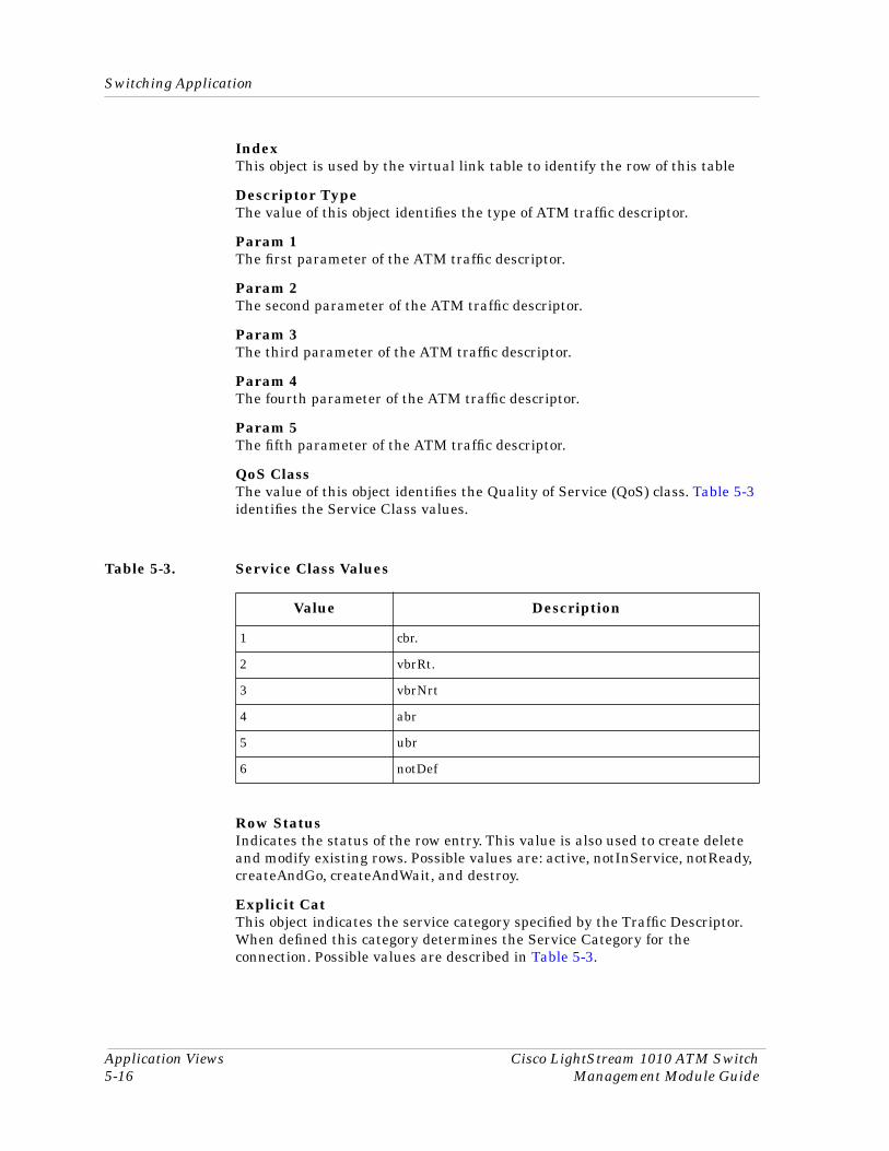
Switching Application
Application Views Cisco LightStream 1010 ATM Switch5-16 Management Module Guide
IndexThis object is used by the virtual link table to identify the row of this table
Descriptor TypeThe value of this object identifies the type of ATM traffic descriptor.
Param 1The first parameter of the ATM traffic descriptor.
Param 2The second parameter of the ATM traffic descriptor.
Param 3The third parameter of the ATM traffic descriptor.
Param 4The fourth parameter of the ATM traffic descriptor.
Param 5The fifth parameter of the ATM traffic descriptor.
QoS ClassThe value of this object identifies the Quality of Service (QoS) class. Table 5-3 identifies the Service Class values.
Row StatusIndicates the status of the row entry. This value is also used to create delete and modify existing rows. Possible values are: active, notInService, notReady, createAndGo, createAndWait, and destroy.
Explicit CatThis object indicates the service category specified by the Traffic Descriptor. When defined this category determines the Service Category for the connection. Possible values are described in Table 5-3.
Table 5-3. Service Class Values
Value Description
1 cbr.
2 vbrRt.
3 vbrNrt
4 abr
5 ubr
6 notDef
9032352 E1 Application Views5-17
Switching Application
Switch Application AAL5 VCC Table View
Derived CatThis object defines the Service Category derived from the Traffic Descriptor. This object mirrors thef Explicit Cat, if that entry is defined and not equal to notDef.
Switch Application AAL5 VCC Table View
IF IndexA unique value used to identify the device.
VPIThe VPI value of the AAL5 VCC at the interface identified by the interface index.
VCIThe VCI value of the AAL5 VCC at the interface identified by the interface index.
ErrorsThe number of AAL5 CPCS PDUs received with the CRC-32 errors on this interface
Time OutsThe number or partially reassembled ALL5 CPCS PDUs which were discarded on this interface because they were not fully reassembled within the required period.
Oversized SDUsThe number of AAL5 CPCS PDUs discarded on this interface because the SDUs were too large.
Switch Application Registered Services View
Instance (IF Index, Service ID, Address Index)The value which uniquely identifies the type of service at the address given by the corresponding address contained in ATM Address.
ATM AddressAn ATM address to which the ATM end-systems on this User Network Interface (UNI) can attempt to establish a connection for the service.
Parameter 1An octet string used according to the value of the Registered Services Service ID.
Row StatusThe status of this row. Possible values are: active, notInService, notReady, createAndGo, createAndWait, and destroy.
Switching ApplicationAccounting Control
Application Views Cisco LightStream 1010 ATM Switch5-18 Management Module Guide
Accounting Control
These views are for the management, collection, and storage of accounting information as pertains to connections in a connection oriented network.
This Icon Subviews menu selection contains the following sub selections.
Switch Application Accounting Selection Control Table View
IndexA unique value that identifies a list or subtree stored in this table.
ListThe combined values of this field and Subtree, specify which data is to be collected.
SubtreeThe combined values of this field and List, specify which data is to be collected.
TypeIndicates the types of connections for which the information selected by this entry are to be collected.
FileThe name of the file into which all accounting information, identified by the index, will be stored. If the index number does not match an actual row in the table, then no data is collected
Row StatusThe status of this row. Possible values are: active, notInService, notReady, createAndGo, createAndWait, and destroy.
Switch Application Accounting File Control Table View
IndexA unique value identifying a file into which accounting data is to be stored. This value is required to be the permanent handle of the entry for as long as it exists.
NameThe name of the file into which the accounting data is to be stored. If the naming convention is a combination of suffixes then the name of the current file is the concatenation of Name and Suffix. The value of this field cannot be modified if the value of Row Status is active.
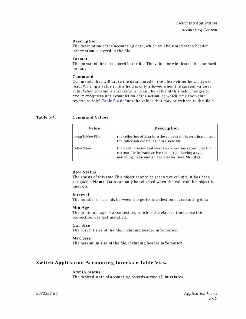
9032352 E1 Application Views5-19
Switching Application
Accounting Control
DescriptionThe description of the accounting data, which will be stored when header information is stored in the file.
FormatThe format of the data stored in the file. The value ber indicates the standard format.
CommandCommands that will cause the data stored in the file to either be written or read. Writing a value to this field is only allowed when the current value is ‘idle’. When a value is successful written, the value of this field changes to cmdInProgress until completion of the action, at which time the value reverts to ‘idle’. Table 5-4 defines the values that may be written to this field.
Row StatusThe status of this row. This object cannot be set to ‘active’ until it has been assigned a Name. Data can only be collected when the value of this object is active.
IntervalThe number of seconds between the periodic collection of accounting data.
Min AgeThe minimum age of a connection, which is the elapsed time since the connection was last installed.
Cur SizeThe current size of the file, including header information.
Max SizeThe maximum size of the file, including header information.
Switch Application Accounting Interface Table View
Admin StatusThe desired state of accounting records across all interfaces.
Table 5-4. Command Values
Value Description
swapToNewFile the collection of data into the current file is terminated, and the collection continues into a new file
collectNow the agent creates and stores a connection record into the current file for each active connection having a type matching Type and an age greater than Min Age
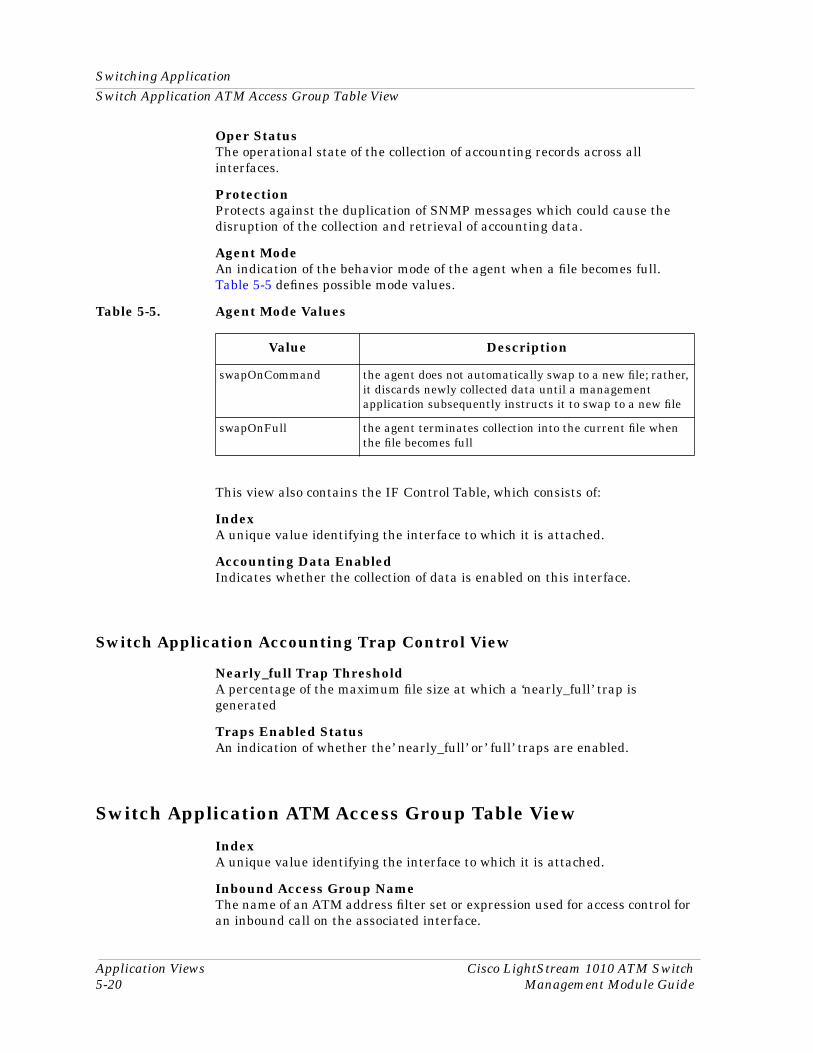
Switching ApplicationSwitch Application ATM Access Group Table View
Application Views Cisco LightStream 1010 ATM Switch5-20 Management Module Guide
Oper StatusThe operational state of the collection of accounting records across all interfaces.
ProtectionProtects against the duplication of SNMP messages which could cause the disruption of the collection and retrieval of accounting data.
Agent ModeAn indication of the behavior mode of the agent when a file becomes full. Table 5-5 defines possible mode values.
This view also contains the IF Control Table, which consists of:
IndexA unique value identifying the interface to which it is attached.
Accounting Data EnabledIndicates whether the collection of data is enabled on this interface.
Switch Application Accounting Trap Control View
Nearly_full Trap ThresholdA percentage of the maximum file size at which a ‘nearly_full’ trap is generated
Traps Enabled StatusAn indication of whether the’ nearly_full’ or’ full’ traps are enabled.
Switch Application ATM Access Group Table View
IndexA unique value identifying the interface to which it is attached.
Inbound Access Group NameThe name of an ATM address filter set or expression used for access control for an inbound call on the associated interface.
Table 5-5. Agent Mode Values
Value Description
swapOnCommand the agent does not automatically swap to a new file; rather, it discards newly collected data until a management application subsequently instructs it to swap to a new file
swapOnFull the agent terminates collection into the current file when the file becomes full
9032352 E1 Application Views5-21
Switching Application
PNNI
Outbound Access Group NameThe name of an ATM address filter set or expression used for access control for an outbound call on the associated interface.
PNNI
This Icon Subviews menu selection contains the following sub selections which contain in-depth information about the device’s Private Network to Network Interface (PNNI functionality)
Switch Application PNNI Base View
Computation EnabledSpecifies whether the background route computation is enabled on this switching system. It is recommended that this field be enabled in large networks due to improved scalability in terms of processing requirements.
Polling IntervalSpecifies how often the switching system polls in order to discover any significant changes that would require a new computation of the background routes.
Insignificant ThresholdSpecifies the number of insignificant changes necessary to trigger a new computation of the background routes.
Resource Management Polling IntervalSpecifies how often Private Network to Network Interface (PNNI) polls resource management to update the values of local interface metrics and attributes.
Administrative Weight ModeSpecifies the mode of default administrative weight assignment for PNNI interfaces. When the value is set to uniform, by default the administrative weight of each PNNI interface is set to 5040, as defined in the ATM Forum PNNI 1.0 specifications. When the value is set to linespeed, by default the administrative weight is set based on the linespeed or maximum cell rate of the interface
Maximum Administrative Weight PercentageSpecifies the maximum acceptable administrative weight for alternate routes as a percentage of the least administrative weight of any route to the destination. This only takes effect when background route computation is enabled.
Route Optimization ThresholdSpecifies the percentage reduction, in the administrative weight of the existing path, required to trigger route optimization.

Switching ApplicationPNNI
Application Views Cisco LightStream 1010 ATM Switch5-22 Management Module Guide
Switch Application PNNI Node Table View
Internal Summary Address(es)Specifies whether automatic generation of an internal summary address based on the switch address or node ID is enabled.
Redistribute Static RoutesSpecifies whether redistribution of ATM static routes to the PNNI routing domain is enabled.
Maximum PTSE RequestsSpecifies the maximum number of PNNI Topology State Elements (PTSEs) that can be requested in one PTSE request packet.
NameThe name of the PNNI node.
Scope MappingSpecifies the configuration mode of the mapping from organizational scope values to PNNI scope.
Double-clicking any entry in this table will open the Switch Application PNNI Node View, which contains the same information as the table view except that it pertains only to the selected entry.
Switch Application PNNI Interface Table View
InterfaceA table of cisco specific attributes used to configure a physical interface or subinterface on a switching system which is capable of being used for PNNI routing.
Link SelectionFor Constant Bit Rate (CBR) or Variable Bit Rate (VBR) setups. Specifies a method for selecting one link out of multiple links with sufficient resources to the same neighbor node. Table 5-6 describes Link Selection values.
Table 5-6. Link Selection Values
Value Description
adminWeightMinimize transmits the call on the interface with the lowest administrative weight
blockingMinimize minimizes subsequent call blocking
transmitSpeedMaximize transmits call on highest speed parallel link
loadBalance balances calls across parallel links
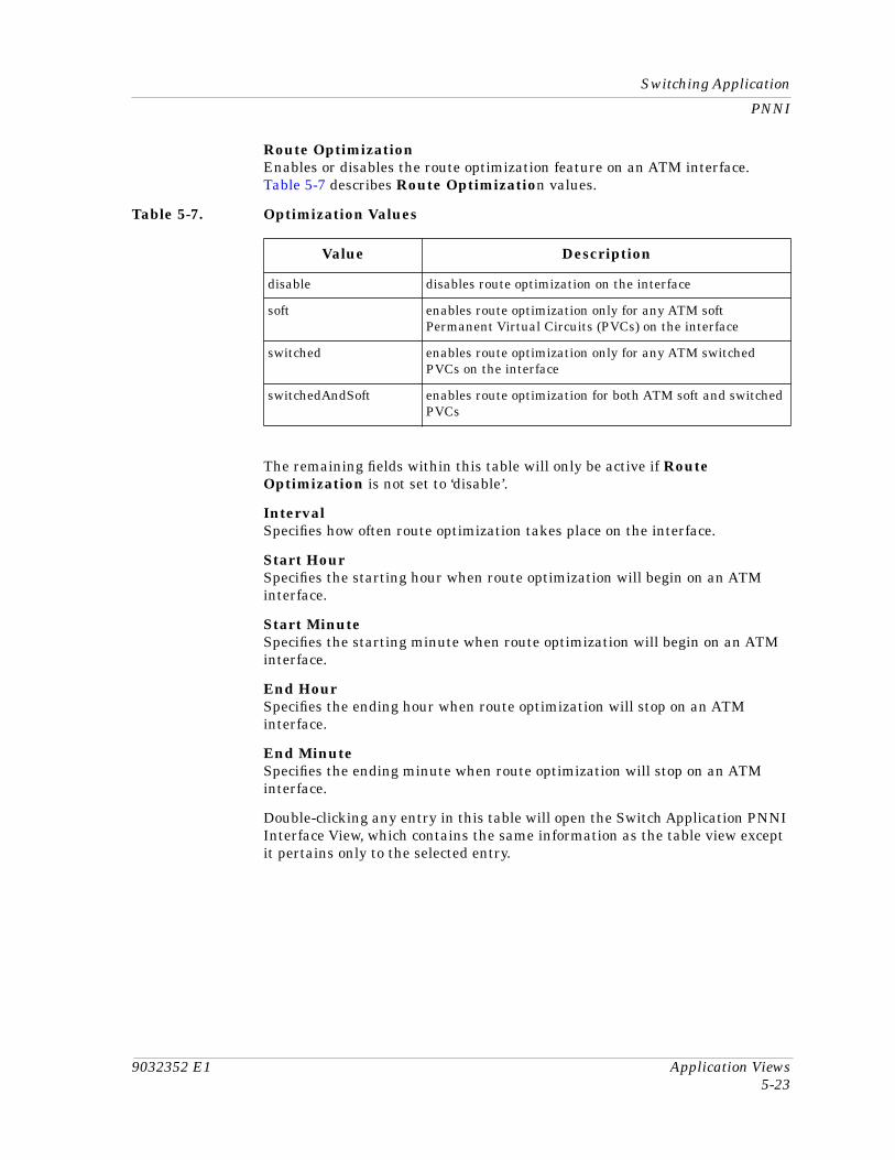
9032352 E1 Application Views5-23
Switching Application
PNNI
Route OptimizationEnables or disables the route optimization feature on an ATM interface. Table 5-7 describes Route Optimization values.
The remaining fields within this table will only be active if Route Optimization is not set to ‘disable’.
IntervalSpecifies how often route optimization takes place on the interface.
Start HourSpecifies the starting hour when route optimization will begin on an ATM interface.
Start MinuteSpecifies the starting minute when route optimization will begin on an ATM interface.
End HourSpecifies the ending hour when route optimization will stop on an ATM interface.
End MinuteSpecifies the ending minute when route optimization will stop on an ATM interface.
Double-clicking any entry in this table will open the Switch Application PNNI Interface View, which contains the same information as the table view except it pertains only to the selected entry.
Table 5-7. Optimization Values
Value Description
disable disables route optimization on the interface
soft enables route optimization only for any ATM soft Permanent Virtual Circuits (PVCs) on the interface
switched enables route optimization only for any ATM switched PVCs on the interface
switchedAndSoft enables route optimization for both ATM soft and switched PVCs
Switching ApplicationPNNI
Application Views Cisco LightStream 1010 ATM Switch5-24 Management Module Guide
Switch Application PNNI Precedence Table View
This table specifies the precedence of different types of reachable addresses, double-clicking any entry within the table will open the Switch Application PNNI Precedence View which contains the same information as the table view except it pertains only to the selected entry. The precedence values are:
1. static local internal with metrics
2. static local exterior
3. static local exterior with metrics
4. PNNI remote internal
5. PNNI remote internal with metrics
6. PNNI remote exterior
7. PNNI remote exterior with metrics
Switch Application Route Address Table View
Instance (Node Index. Route Address. Prefix Length. Route Address Index.)An entry containing Cisco specific PNNI information about a reachable address prefix.
Forwarding E164 AddressThe native E.164 address used as the called party address when the call matching pnniRouteAddrAddress is forwarded across the interface identified by pnniRouteAddrIfIndex.
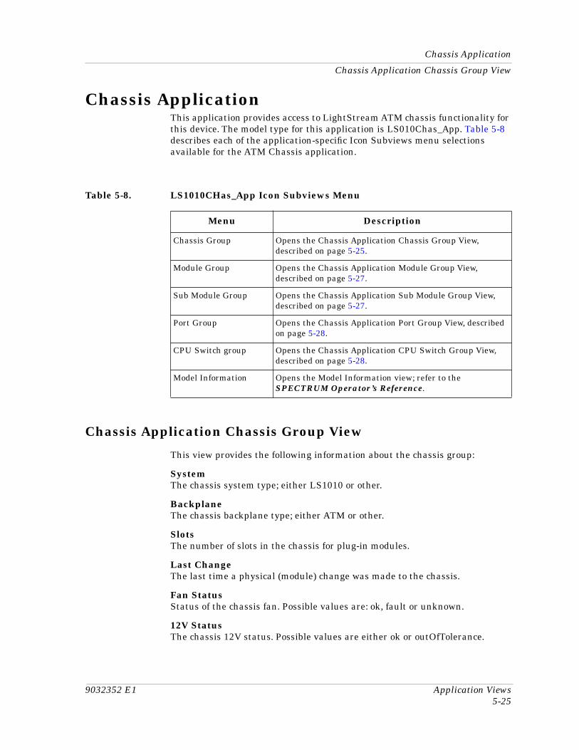
9032352 E1 Application Views5-25
Chassis Application
Chassis Application Chassis Group View
Chassis ApplicationThis application provides access to LightStream ATM chassis functionality for this device. The model type for this application is LS010Chas_App. Table 5-8 describes each of the application-specific Icon Subviews menu selections available for the ATM Chassis application.
Chassis Application Chassis Group View
This view provides the following information about the chassis group:
SystemThe chassis system type; either LS1010 or other.
BackplaneThe chassis backplane type; either ATM or other.
SlotsThe number of slots in the chassis for plug-in modules.
Last ChangeThe last time a physical (module) change was made to the chassis.
Fan StatusStatus of the chassis fan. Possible values are: ok, fault or unknown.
12V StatusThe chassis 12V status. Possible values are either ok or outOfTolerance.
Table 5-8. LS1010CHas_App Icon Subviews Menu
Menu Description
Chassis Group Opens the Chassis Application Chassis Group View, described on page 5-25.
Module Group Opens the Chassis Application Module Group View, described on page 5-27.
Sub Module Group Opens the Chassis Application Sub Module Group View, described on page 5-27.
Port Group Opens the Chassis Application Port Group View, described on page 5-28.
CPU Switch group Opens the Chassis Application CPU Switch Group View, described on page 5-28.
Model Information Opens the Model Information view; refer to the SPECTRUM Operator’s Reference.
Chassis ApplicationChassis Application Chassis Group View
Application Views Cisco LightStream 1010 ATM Switch5-26 Management Module Guide
Enet Link LEDEthernet Link status LED of the CPU card. Possible values are: off, yellow, red and green.
Fan LEDLED status of fan. Possible values are: off, red, yellow or green.
Temperature StatusThe chassis temperature status. Possible values are either ok or overTemperature.
CPU Status LEDLED status of the CPU card. Possible values are: off, red, yellow, and green.
PCMCIA Slot 0 TypeType of PCMCIA slot for 0. Possible values are: unknown, empty, and flash.
Power Supply 0
TypeThe type of power supply. Possible values are: powerone, astec, and empty.
Admin StatusEnable or disable power supply 0.
StatusStatus of power supply 0. Possible values are: ok, fault, and unknown
LEDLED status of power supply 0. Possible values are: red, yellow, green, and off.
PCMCIA Slot 1 TypeType of PCMCIA slot for 1. Possible values are: unknown, empty, and flash.
Power Supply 1
TypeThe type of power supply. Possible values are: powerone, astec, and empty.
Admin StatusEnable or disable power supply 1.
StatusStatus of power supply 1. Possible values are: ok, fault, and unknown.
LEDLED status of power supply 1. Possible values are: red, yellow, green, and off.
Chassis Failure ActionThe action to take when there is any chassis failure, including: power failure, voltage, temperature and fan failure. Possibilities are: shutdown, send a trap, send a trap and shutdown, and nothing
Chassis Change ActionThe action to take when there is any chassis change, including: a change to the power supply, fan or any boards. Possibilities are nothing or send a trap.
9032352 E1 Application Views5-27
Chassis Application
Chassis Application Module Group View
Chassis Application Module Group View
In addition to the following information, this table also provides double-click access to the Chassis Application Module Group Configuration View. For more information on table views, see Chapter 1, Introduction.
ModuleA unique value that identifies each module.
TypeThe type of module.
Serial #The serial number of the module.
Hw VersionThe hardware version of the module.
Sw VersionThe software version of the module.
DescriptionA descriptive string used by the agent to describe the module.
Sub ModulesThe maximum number of sub-modules supported on this module.
Admin StatusThe administrative status of the module. Possible values are: enable, disable, and reset.
Chassis Application Sub Module Group View
In addition to the following information, this table also provides double-click access to the Chassis Application Sub Module Group Configuration View. For more information on table views, see Chapter 1, Introduction.
ModuleThe module identifier to which the sub-module is attached.
Sub ModuleA unique value for each sub-module within the module. This value is determined by the sub-slot number where the sub-module is attached.
TypeThe type of sub-module. Possible types are: other, oc3Utp, oc3SingleModeFiber, oc12SingleModeFiber, oc3MultiModeFiber, oc12MultiModeFiber, ds, e3, cpuSwitch, featureFpga, and featureAsic.
Serial #The serial number of the sub-module.
Chassis ApplicationChassis Application Port Group View
Application Views Cisco LightStream 1010 ATM Switch5-28 Management Module Guide
Hw VersionThe hardware version of the sub-module.
Sw VersionThe software version of the sub-module.
DescriptionA descriptive string used by the agent to describe the sub-module.
PortsThe maximum number of ports supported by this sub-module.
Admin StatusThe administrative status of this sub-module. Possible values are reset and ok.
Chassis Application Port Group View
This view provides the following information:
Module A unique value that identifies the module to which this port is attached.
Sub ModuleA unique value that identifies the sub-module to which this port is attached.
PortA unique value identifying each port attached to a sub-module.
InterfaceA cross reference to the port’s interface index.
Chassis CPU Switch View
This view provides the following information:
Total Cell Buffer CountThe total cell buffer count in the switch’s shared memory.
Free Cell Buffer CountThe total number of free cell buffers in the switch’s shared memory.
Total Cells DiscardedThe total cells discarded by the switch.
Total Invalid CellsThe number of invalid cells on the switch.
CPU Admin StatusCPU Administrative status of the switch. Possible values are ok and reset.
9032352 E1 Application Views5-29
Chassis Application
Chassis CPU Switch View
Terminate OAM FlowTerminate all the incoming OAM cells to the CPU port.
IndexA unique number used to identify the chassis CPU switch.
Invalid Cell HeaderA list of invalid cell header entries.
Cisco Chassis ApplicationChassis Card View
Application Views Cisco LightStream 1010 ATM Switch5-30 Management Module Guide
Cisco Chassis ApplicationThis application provides access to Cisco ATM Interface functionality for this device. The model type for this application is CiscoChas_App. Table 5-9 describes each of the application-specific Icon Subviews menu selections available for the ATM Interface application.
Chassis Card View
This view displays the Chassis Slot Table, which provides the following information on the cards contained in the chassis:
SlotThe slot number in which this card is installed. If the slot number is not applicable or not determinable, this field will display-1.
TypeThe functional type of the card installed in this slot. The following values are possible types: Unknown, csc1, csc2, csc3, csc4, rp, csc-m, csc-mt, csc-mc, csc-mcplus, csc-envm, csc-16, csc-p, csc-a, csc-e1, csc-e2, csc-y, csc-s, csc-t, sci4s, sci2s2t, sci4t, mci1t, mci2t, mci1s, mci1s1t, mci2s, mci1e, mci1e1t, mci1e2t, mci1e1s, mci1e1s1t, mci1e2s, mci2e, mci2e1t, mci2e2t, mci2e1s, mci2e1s1t, mci2e2s, csc-r, csc-r16, csc-r16m, csc-1r, csc-2r, csc-cctl1, csc-cctl2, csc-mec2, csc-mec4, csc-mec6, csc-fci, csc-fcit, csc-hsci, csc-ctr, sp, eip, fip, hip, sip, trip, fsip, aip, mip, ssp, npm-4000-fddi-sas, npm-4000-fddi-das, npm-4000-1e, npm-4000-1r, npm-4000-2s, npm-4000-2e1, npm-4000-2e, npm-4000-2r1, npm-4000-2r, npm-4000-4t.
DescriptionA description of this card.
Software Ver.The version number of the firmware installed on this card. If no version number is available, this field will remain empty.
Hardware Ver.The hardware revision level of this card. If no revision level is available, this field will remain empty.
Table 5-9. CiscoChas_App Icon Subviews Menu
Menu Description
Card Information Opens the Chassis Card View, described on page 5-30.
General Opens the Chassis General Information View, described on page 5-31.
Model Information View Opens the Model Information View; refer to the SPECTRUM Operator’s Reference.
9032352 E1 Application Views5-31
Cisco Chassis Application
Chassis General Information View
Serial No.The serial number of this card. If no serial number is available, this field will contain a zero.
Chassis General Information View
This view displays information on the chassis in which the switch is installed. This view is divided into the three sections described below.
Chassis Information
This section of the Chassis Card View provides physical information about the chassis. The following information is provided:
Hardware Revision LevelThe version number of the chassis hardware. If the version number is not available, this field will remain empty.
Chassis TypeThe type of chassis. Possible chassis types are Unknown, Multibus, Agsplus, Igs, c2000, c3000, c4000, c7000, cs-500, c7010, c2500, and c4500.
Chassis ID/Serial No.A unique identifier for this chassis. The default value is the serial number of the chassis. If no serial number is available and no alternative ID has been set for the chassis, this field will remain empty.
Number of Chassis SlotsThe number of slots in this chassis model.
ROM Information
This section of the Chassis Card View provides the following information about the ROM installed in the chassis:
ROM Monitor VersionThe version number of the ROM monitor.
ROM Software VersionThe version number of the ROM system software. If no version number is available, this field will remain empty.
Config RegisterThe current value of the configuration register.
Cisco Interface ApplicationChassis General Information View
Application Views Cisco LightStream 1010 ATM Switch5-32 Management Module Guide
RAM Information
This section of the Chassis Card View provides the following information about the RAM installed in the chassis:
System CPU RAM (bytes)The amount of RAM available to the CPU, displayed in bytes.
Non-volatile RAM Used (bytes)The amount of non-volatile configuration memory in use, displayed in bytes.
Non-volatile RAM Size (bytes)The total size, in bytes, of non-volatile configuration memory.
Cisco Interface ApplicationThis application provides access to ATM Interface functionality for this device. The model type for this application is CiscoIFApp. Opening the Icon Subviews menu will reveal the Model Information view which is described in the Operator’s Reference.
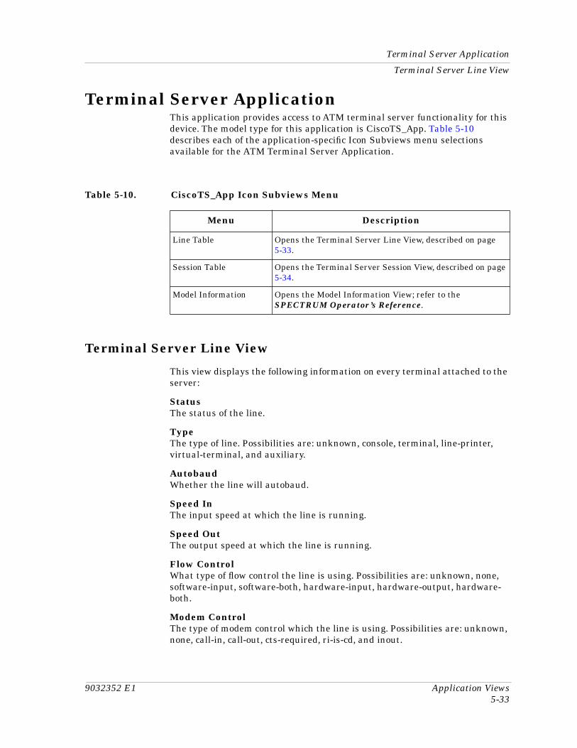
9032352 E1 Application Views5-33
Terminal Server Application
Terminal Server Line View
Terminal Server ApplicationThis application provides access to ATM terminal server functionality for this device. The model type for this application is CiscoTS_App. Table 5-10 describes each of the application-specific Icon Subviews menu selections available for the ATM Terminal Server Application.
Terminal Server Line View
This view displays the following information on every terminal attached to the server:
StatusThe status of the line.
TypeThe type of line. Possibilities are: unknown, console, terminal, line-printer, virtual-terminal, and auxiliary.
AutobaudWhether the line will autobaud.
Speed InThe input speed at which the line is running.
Speed OutThe output speed at which the line is running.
Flow ControlWhat type of flow control the line is using. Possibilities are: unknown, none, software-input, software-both, hardware-input, hardware-output, hardware-both.
Modem ControlThe type of modem control which the line is using. Possibilities are: unknown, none, call-in, call-out, cts-required, ri-is-cd, and inout.
Table 5-10. CiscoTS_App Icon Subviews Menu
Menu Description
Line Table Opens the Terminal Server Line View, described on page 5-33.
Session Table Opens the Terminal Server Session View, described on page 5-34.
Model Information Opens the Model Information View; refer to the SPECTRUM Operator’s Reference.
Terminal Server ApplicationTerminal Server Session View
Application Views Cisco LightStream 1010 ATM Switch5-34 Management Module Guide
LocationThe line’s physical location.
Term TypeThe line’s terminal type.
Length In LinesLength, in lines, of the terminal’s screen, attached to this line.
Width in CharWidth, in characters, of the terminal’s screen, attached to this line.
Escape CharEscape character used to break out of active sessions.
Idle Time OutThe time, in seconds, before a timeout condition will occur.
Session Time OutThe time, in seconds, before a session timeout condition will occur.
RotaryThe rotary group number the line belongs to.
# of ConnectionsNumber of times a connection has been made to or from this line.
Current SessionCurrent number of sessions in use on this line.
UserTACACS user name, if TACACS is enabled.
NoiseCount of garbage characters received when the line is inactive.
Line NumberA unique value used to identify the line.
Time ActiveThe time, in seconds, since the line was activated.
Terminal Server Session View
This view provides the following information about all current sessions attached to the server:
TypeThe type of session. Possibilities are: unknown, pad, stream, rlogin, telnet, tcp, lat, mop, slip, xrfemote, and rshell.
DirectionThe direction of the session.
9032352 E1 Application Views5-35
Terminal Server Application
Terminal Server Session View
AddrThe remote host address of the session.
NameThe remote host name of the session.
StateA boolean value indicating whether the session is active.
IdleTime, in seconds, that the session has been idle.
LineA unique value used to identify the line.
SessionA unique value used to identify the session.

Terminal Server ApplicationTerminal Server Session View
Application Views Cisco LightStream 1010 ATM Switch5-36 Management Module Guide
9032352 E11
IndexAAccounting Control 5-18Active SVCs 3-3Active SVPs 3-3Adminisrtative Status 2-4Administrative Status Label 2-3, 2-4Alarm Discard Threshold 2-11Application View 5-1, 5-2Apply 2-14ATM IF Configuration Table
Address Type 3-14Admin Address 3-14Conf VPCs 3-13Config VCCs 3-13IF Index 3-13ILMI VCI 3-14ILMI VPI 3-14Max VCCs 3-13Max VCI Bits 3-14Max VPCs 3-13Max VPI Bits 3-14Neighbor Address 3-14Neighbor IF Name 3-14
ATM Switch ApplicationVPL Table View 5-15
ATM Switch Application VPL Table ViewLast Change 5-15VPI 5-15
Attribute Selected 2-12
CC Bit Parity Errors 2-8Cast Type 2-10Chassis
Configuration View 3-2, 3-4Contact 3-2Description 3-2Location 3-2Serial Number 3-2Slot Table 5-30Type 3-2
Version 3-2Chassis Application
Chassis Group View 5-2512V Status 5-25Admin Status 5-26Backplane 5-25Chassis Change Action 5-26Chassis Failure Action 5-26CPU Status LED 5-26Enet Link LED 5-26Fan LED 5-26Fan Status 5-25Last Change 5-25LED 5-26PCMCIA Slot 0 Type 5-26PCMCIA Slot 1 Type 5-26Power Supply 0 5-26Power Supply 1 5-26Slots 5-25Status 5-26System 5-25Temperature Status 5-26Type 5-26
Module Group View 5-27Admin Status 5-27Description 5-27Hw Version 5-27Module 5-27Serial # 5-27Sub Modules 5-27Sw Version 5-27Type 5-27
Port Group View 5-28Sub Module Group View 5-27
Chassis ApplictionPort Group
Interface 5-28Module 5-28Port 5-28Sub Module 5-28
Sub Module GroupAdmin Status 5-28Description 5-28
Index Cisco LightStream 1010 ATM Switch2 Management Module Guide
Hw Version 5-28Module 5-27Ports 5-28Serial # 5-27Sub Module 5-27Sw Version 5-28Type 5-27
Chassis Card View 5-30Description 5-30Hardware Ver. 5-30Serial Number 5-31Slot 5-30Software Ver. 5-30Type 5-30
Chassis CPU Switch View 5-28CPU Admin Status 5-28Free Cell Buffer Count 5-28Index 5-29Invalid Cell Header 5-29Terminate OAM Flow 5-29Total Cell Buffer Count 5-28Total Cells Discarded 5-28Total Invalid Cells 5-28
Chassis Device View 2-2Chassis General Information View 5-31Chassis Information 5-31
Chassis ID/Serial No. 5-31Chassis Type 5-31Hardware Revision Level 5-31Number of Chassis Slots 5-31
Chassis Manager Application View 5-4Cisco Chassis Application 5-30Cisco LightStream 1010 ATM Switch
xiCiscoChas_App 5-30CiscoChasApp 5-1CiscoIFApp 5-1CiscoTS_App 5-33CiscoTSApp 5-1Close 2-14Common Applications 5-1Config Type 2-10Configuration View 3-1Configured VPs 3-3Connections 2-8Cross Connect Table View 5-7
Row Status Procedure 5-7
DDefault Button 2-14Device Application View 5-2
Icon mode 5-2List mode 5-2
Device Configuration ViewContact Status 3-4IF Address Translation 3-4Interface Configuration Table 3-4
Admin Status 3-5Bandwidth 3-5Description 3-5Index 3-4Last Change 3-5Oper Status 3-5Packet Size 3-5Physical Address 3-5Type 3-5
Number of Interfaces 3-4Reconfigure 3-4Router Redundancy 3-4
Device IconAdministrative Status Label 2-4Interface Label 2-4Interface Status View 2-4
Administrative Status 2-4Interface Type Label 2-4InterfaceType Label 2-4Operational Status 2-4
Device Icon Subviews Menu 2-8Device Identification Labels 2-6Device Name 3-4Device Views 2-1
banner 2-2Direction 5-34documentation
conventions xiiorganization xi
EEnvironmental
Device ViewAccessing 2-2
Error Rate Threshold 2-11
FFast Ethernet Application 5-29
9032352 E1 Index3
GGauge
Buttons 2-14Label 2-6Mode 2-13Selected Attribute 2-13Type 2-13
Gauge Label 2-3Getting Help xiii
HHDLC 2-5
IICMP_App 5-1IF Index 2-9If Index 2-8IFChas_App 5-32In Cells 2-10Interface
Index 2-6Status of 2-4Type 2-5
Interface IconInterface label 2-4
Interface Icon, Device View 2-2Administrative Status Label 2-4Gauge Label 2-6Network Information Label 2-6
Interface Label 2-4Interface Options Panel 2-13Interface Resource Management
State Information# Permanent Conns 3-11# Signalled Conns 3-11Alloc Cell Rate (TX) 3-10Avail Cell Rate (TX) 3-10Max Cell Trans. Delay 3-11Peak to Peak CTD 3-11TX Cell Loss Ratio 3-11
Statistics InformationFailed (BE Limit) 3-12Failed (Cell Delay Var) 3-12Failed (Cell Loss) 3-11Failed (Delay) 3-11Failed (Lack Bandwidth) 3-11Failed (Other) 3-12
Failed (Parm Limit) 3-12Failed (Trafic Params) 3-11Successful 3-11Total Alloc Requests 3-11
Traffic Flow Direction ViewLink Share Max CBR 3-8Link Share Max VBR 3-9Link Share Min CBR 3-8Link Share Min VBR 3-9Max ABR PCR 3-10Max ABR Tolerance 3-10Max Aggregate 3-8Max CBR PCR 3-9Max CBR Tolerance 3-9Max UBR PCR 3-10Max UBR Tolerance 3-10Max VBR PCR 3-9Max VBR SCR 3-9Max VBR Tolerance 3-10
Interface Resource Management Output Queue Configuration
Cell Coun 3-12Inst. Max Size 3-12Max Size Force 3-12Req. Max Size 3-12Service Cat 3-12
Interface Resource Management StateInformation
Alloc Cell Rate (RX) 3-10Interface Resourcee Management
State InformationAvail Cell Rate (RX) 3-10
Interface Status View 2-4Administrative Status 2-4Interface Type Label 2-4Operational Status 2-4
Interface Type Label 2-3, 2-4IP Application 5-1
KKeep Settings Button 2-14
LLast
Attachment Change 3-3Configuration Change 3-3Physical Change 3-3
Index Cisco LightStream 1010 ATM Switch4 Management Module Guide
LCV Errors 2-8LightStream IF Configuration Table
Active SVCs 3-15Active SVPs 3-14Connections 3-14IF Index 3-14PVCs 3-14PVPs 3-14Recv Cells 3-15Xmit Cells 3-15
LightStream Interface Address Translation Table View 2-3
LightStream Interface Configuration View 2-3
LightStream Interface Resource Management Thresholds View
Discard 3-13EFCI 3-13
LightStream Switch Application Traffic Parameter Table View 5-15
LightStream Switch Application Virtual Channel Link Table View 5-10
Link Table View 5-10Row Status Procedure 5-10
Links 2-10Load Alarm Threshold 2-11Low VPI 5-8LS_Switch_App 5-1, 5-5LS010Chas_App 5-25LS10Chas_App 5-1
MMAC Address Label 2-6Mac Address Label 2-3MIB-II 5-1Model Information 5-5Module 5-28Module Configuration 3-1
NNetwork Address 2-6Network Address Label 2-3NMM Agent Configuration 3-1Notice i
OOperational Status 2-4Out Cells 2-10
PP Bit Parity Errors 2-8Packet Threshold 2-11Path Parity Errors 2-8Performance Statistics 2-6Physical Address 2-6Plcp Bip Violations 2-8PNNI 5-21PVCs 3-3PVPs 3-3
RRAM Information 5-32
Non-volatile RAM Size (bytes) 5-32Non-volatile RAM Used (bytes) 5-32System CPU RAM (bytes) 5-32
Received Cells 3-3Redundancy Table 5-5Related Reading xiiiReset 2-14Restricted Rights Notice iiROM Information 5-31
Config Register 5-31Monitor Version 5-31Software Version 5-31
RS-232 App 5-1
SSection Parity Errors 2-8SEHI100TX-22 Device 1-1Selected Attribute 2-13SNMP2_Agent 5-1Span Type 2-10SPECTRUM Device Management 1-2Status 2-8SVC Addresses 2-9SVC Direction 2-9SVC Minimum VCI 3-3SVP Address 2-9SVP Direction 2-9SVP’s VPI 2-9
9032352 E1 Index5
Switch ApplicationAAL5 VCC Table View 5-17
Errors 5-17AAL5VCC Table View
IF Index 5-17Oversized SDUs 5-17Time Outs 5-17VCI 5-17VPI 5-17
Accounting File Control Table ViewCommand 5-19Cur Size 5-19Description 5-19Format 5-19Index 5-18Interval 5-19Max Size 5-19Min Age 5-19Name 5-18Row Status 5-19
Accounting Interface Table ViewAccounting Data Enabled 5-20Admin Status 5-19Agent Mode 5-20Index 5-20Oper Status 5-20Protection 5-20
Accounting Selection Control Table ViewFile 5-18Index 5-18List 5-18Row Status 5-18Subtree 5-18Type 5-18
Accounting Trap Control ViewNearly_full Trap Threshold 5-20Traps Enabled Status 5-20
Application Addresses ViewAddress 5-15Index 5-15Row Status 5-15
Application ATM Access Group Table View
Inbound Access Group Name 5-20Index 5-20Outbound Access Group Name 5-21
Application Route Address Table ViewForwarding E164 Address 5-24Instance 5-24
DS3 PLCP Table View 5-6
Alarm State 5-7IF Index 5-6SEFSs 5-7UASs 5-7
Interface Virtual Channel Link Table Extension View 5-12
AAL Encap Flag 5-13AAL Encap Protocols 5-13AAL User VC Type 5-13Atm in Arp Interval 5-13Cast Type 5-13Config Type 5-14Conn State 5-14Cross IF Index 5-12Cross VCI 5-12Cross VPI 5-12EPD Enable 5-14In Cells 5-13Install Time 5-12Last Release Cause 5-13Location 5-13Next Leaf IF Index 5-13Next Leaf VCI 5-13Next Leaf VPI 5-13Num Attempts 5-12OAM AIS Enable 5-12OAM End Loopback 5-12OAM RDI Enable 5-12Out Cells 5-13Remote Addr 5-14Remote VCI 5-14Remote VPI 5-14Rx UPC Mode 5-14Slow Retry Interval 5-12Span Type 5-13
PNNI Base ViewAdministrative Weight Mode 5-21Computation Enabled 5-21Insignificant Threshold 5-21Maximum Administrative Weight
Percentage 5-21Polling Interval 5-21Resource Management Polling
Interval 5-21Route Optimization Threshold 5-21
PNNI Interface Table ViewEnd Hour 5-23End Minute 5-23Interface 5-22Interval 5-23
Index Cisco LightStream 1010 ATM Switch6 Management Module Guide
Link Selection 5-22Route Optimization 5-23Start Hour 5-23Start Minute 5-23
PNNI Node Table ViewInternal Summary Address(es) 5-22Maximum PTSE Requests 5-22Name 5-22Redistribute Static Routes 5-22Scope Mapping 5-22
Registered Services ViewATM Address 5-17Instance (IF Index, Service ID,
Address Index) 5-17Parameter 1 5-17Row Status 5-17
TC Sublayer Table ViewIF Index 5-6OCD Events 5-6TC Alarm Status 5-6
Traffic Parameter Table ViewDerived Cat 5-17Descriptor Type 5-16Explicit Cat 5-16Index 5-16Param 1 5-16Param 2 5-16Param 3 5-16Param 4 5-16Param 5 5-16QoS Class 5-16Row Status 5-16
VCL Table ViewAAL Type 5-11Admin Status 5-11Cross Connect Id 5-11Encaps Type 5-11IF 5-10LightStream Table Extension 5-12Oper Status 5-11Row Status 5-11Rx Index 5-11Rx Size 5-11VCI 5-11Xmit Index 5-11Xmit Size 5-11
Virtual Channel Cross Connect Table View
Admin Status 5-8High IF 5-8
High VCI 5-8High VPI 5-8Index 5-8Low IF 5-8Low VCI 5-8
Virtual Channel Cross Connect View 5-9H2L Last Change 5-9H2L Op Status 5-9L2H Last Change 5-9L2H Op Status 5-9
Virtual Path Cross Connect Table ViewIndex 5-9
Virtual Path Cross Connect ViewH2L Last Change 5-10H2L Op Status 5-10L2H Last Change 5-10L2H Op Status 5-10
Switch Application Accounting File Control Table View 5-18
Switch Application Accounting Interface Table View 5-19
Switch Application Accounting Selection Control Table View 5-18
Switch Application Addresses View 5-15Switch Application Interface Configuration
View 3-1Switch Application Registered Services
View 5-17Switch Application TC Sublayer Table
View 5-6Switch Application VCL Table View 5-10Switch Application VCL View 5-12Switch Application Virtual Channel Cross
Connect Table ViewRow Status 5-8
Switch Application Virtual Path Cross Connect Table View 5-9, 5-10
Admin Status 5-9High VPI 5-9Low Index 5-9Low VPI 5-9Row Status 5-9
Switch Application Virtual Path Link Table View 5-14
Switch Application VPL Table ViewAdmin Status 5-14Cross Connect Id 5-15IF 5-14Oper Status 5-14Rcv Descr Index 5-14
9032352 E1 Index7
Row Status 5-15Xmit Descr Index 5-14
Switch Interface Physical Layer view 5-7Switch Resource Management
Configuration 3-1Switch Resource Management Configuration
Details View 3-1Switch Resource Management Configuration
ViewDefault QOS Objective 3-5
Peak to Peak CDV 3-6QOS CLR 3-6QOS Max 3-5
Queued Cells 3-6ABR Congestion Notify 3-6Cell Count 3-6Cell Limit 3-6Over Subscription Factor 3-6Priority 3-6SCR Margin Factor 3-6
Switched Resource Management Configuration Details View
Best Effort Limit 3-7Force 3-7IF Index 3-7Link Distance 3-7Out Pacing 3-7Output Queues 3-7Rate Installed 3-7Rate Requested 3-7Service Category 3-7Traffic Flow 3-7
Switching Application 5-5System2_App 5-1
TTCP (TCP2_App) 5-1TCP/IP Based Networks xiiiTerminal Server Application Views 5-33Terminal Server Line View
# of Connections 5-34Autobaud 5-33Current Session 5-34Escape Char 5-34Flow Control 5-33Idle Time Out 5-34Length In Lines 5-34Line Number 5-34Location 5-34
Modem Control 5-33Noise 5-34Rotary 5-34Session Time Out 5-34Speed In 5-33Speed Out 5-33Status 5-33Term Type 5-34Time Active 5-34Type 5-33User 5-34Width in Char 5-34
Terminal Server Sesion ViewAddr 5-35Idle 5-35Line 5-35Name 5-35Session 5-35State 5-35Type 5-34
Terminal Server Session View 5-34Total
Attachment Changes 3-3Configuration Changes 3-3Physical Changes 3-2
Trademarks i
UUDP Application 5-1
VVC 2-10VC Dest Address 3-4VCI Value 2-9Virtual Paths 2-11Virus Disclaimer iVPI 2-10, 5-11VPI Value 2-9
XXmit Led 3-3