Embed Size (px)
Citation preview
White paper
Cisco public
© 2017 Cisco and/or its affiliates. All rights reserved. This document is Cisco Public Information. Page 1 of 18
Cisco Nexus 9300-EX Platform Switches Architecture
White paper
Cisco public
© 2017 Cisco and/or its affiliates. All rights reserved. This document is Cisco Public Information. Page 2 of 18
Content
Introduction ............................................................................................................................................ 3
Cisco Nexus 9300-EX platform overview .................................................................................................... 4
Cisco Nexus 93180YC-EX switch architecture ........................................................................................................................ 5 Cisco Nexus 93108TC-EX switch architecture ........................................................................................................................ 6 Cisco Nexus 93180LC-EX switch architecture ......................................................................................................................... 7
Cisco cloud scale ASICs in Cisco Nexus 9300-EX platform ............................................................................. 7
Cisco cloud scale LSE ASIC architecture ...................................................................................................... 7
LSE forwarding table ............................................................................................................................................................. 8 LSE buffer architecture .......................................................................................................................................................... 9 Buffer allocation .................................................................................................................................................................. 10 Intelligent buffer management ............................................................................................................................................ 12
Approximate fair discard ........................................................................................................................................................... 12 Dynamic packet prioritization ................................................................................................................................................... 13
Cisco Nexus 9300-EX platform unicast packet forwarding .......................................................................... 14
Forwarding pipelines on LSE ASICs ...................................................................................................................................... 14 Ingress pipeline: input forwarding controller ........................................................................................................................ 15
Packet-header parsing .............................................................................................................................................................. 15 Layer 2 and layer 3 forwarding lookup ....................................................................................................................................... 15 Ingress ACL processing .............................................................................................................................................................16 Ingress traffic classification .......................................................................................................................................................16 Ingress forwarding result generation .........................................................................................................................................16
Ingress pipeline: input data-path controller ......................................................................................................................... 16 Broadcast network and central statistics module .......................................................................................................................16
Egress pipeline: output data-path controller ........................................................................................................................ 16 Egress pipeline: output forwarding controller ....................................................................................................................... 17
Cisco Nexus 9300-EX platform multicast packet forwarding ....................................................................... 17
Conclusion ............................................................................................................................................. 18
For more information ............................................................................................................................. 18
White paper
Cisco public
© 2017 Cisco and/or its affiliates. All rights reserved. This document is Cisco Public Information. Page 3 of 18
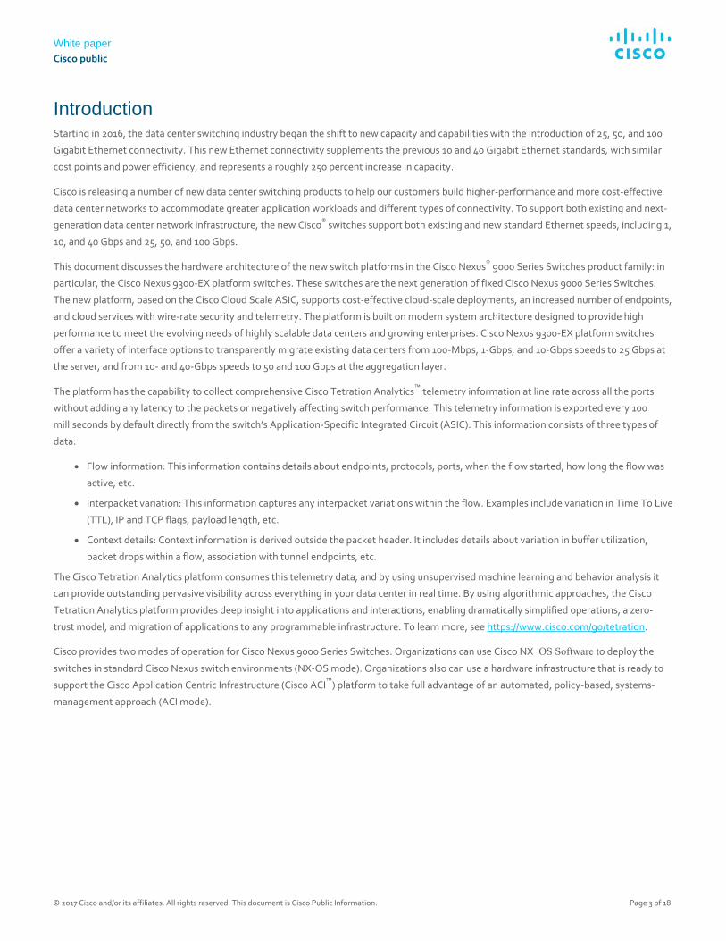
Introduction Starting in 2016, the data center switching industry began the shift to new capacity and capabilities with the introduction of 25, 50, and 100
Gigabit Ethernet connectivity. This new Ethernet connectivity supplements the previous 10 and 40 Gigabit Ethernet standards, with similar
cost points and power efficiency, and represents a roughly 250 percent increase in capacity.
Cisco is releasing a number of new data center switching products to help our customers build higher-performance and more cost-effective
data center networks to accommodate greater application workloads and different types of connectivity. To support both existing and next-
generation data center network infrastructure, the new Cisco® switches support both existing and new standard Ethernet speeds, including 1,
10, and 40 Gbps and 25, 50, and 100 Gbps.
This document discusses the hardware architecture of the new switch platforms in the Cisco Nexus® 9000 Series Switches product family: in
particular, the Cisco Nexus 9300-EX platform switches. These switches are the next generation of fixed Cisco Nexus 9000 Series Switches.
The new platform, based on the Cisco Cloud Scale ASIC, supports cost-effective cloud-scale deployments, an increased number of endpoints,
and cloud services with wire-rate security and telemetry. The platform is built on modern system architecture designed to provide high
performance to meet the evolving needs of highly scalable data centers and growing enterprises. Cisco Nexus 9300-EX platform switches
offer a variety of interface options to transparently migrate existing data centers from 100-Mbps, 1-Gbps, and 10-Gbps speeds to 25 Gbps at
the server, and from 10- and 40-Gbps speeds to 50 and 100 Gbps at the aggregation layer.
The platform has the capability to collect comprehensive Cisco Tetration Analytics™ telemetry information at line rate across all the ports
without adding any latency to the packets or negatively affecting switch performance. This telemetry information is exported every 100
milliseconds by default directly from the switch’s Application-Specific Integrated Circuit (ASIC). This information consists of three types of
data:
● Flow information: This information contains details about endpoints, protocols, ports, when the flow started, how long the flow was
active, etc.
● Interpacket variation: This information captures any interpacket variations within the flow. Examples include variation in Time To Live
(TTL), IP and TCP flags, payload length, etc.
● Context details: Context information is derived outside the packet header. It includes details about variation in buffer utilization,
packet drops within a flow, association with tunnel endpoints, etc.
The Cisco Tetration Analytics platform consumes this telemetry data, and by using unsupervised machine learning and behavior analysis it
can provide outstanding pervasive visibility across everything in your data center in real time. By using algorithmic approaches, the Cisco
Tetration Analytics platform provides deep insight into applications and interactions, enabling dramatically simplified operations, a zero-
trust model, and migration of applications to any programmable infrastructure. To learn more, see https://www.cisco.com/go/tetration.
Cisco provides two modes of operation for Cisco Nexus 9000 Series Switches. Organizations can use Cisco NX‑OS Software to deploy the
switches in standard Cisco Nexus switch environments (NX-OS mode). Organizations also can use a hardware infrastructure that is ready to
support the Cisco Application Centric Infrastructure (Cisco ACI™) platform to take full advantage of an automated, policy-based, systems-
management approach (ACI mode).
White paper
Cisco public
© 2017 Cisco and/or its affiliates. All rights reserved. This document is Cisco Public Information. Page 4 of 18
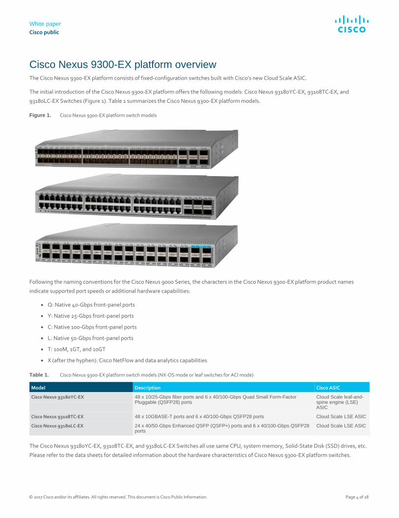
Cisco Nexus 9300-EX platform overview The Cisco Nexus 9300-EX platform consists of fixed-configuration switches built with Cisco’s new Cloud Scale ASIC.
The initial introduction of the Cisco Nexus 9300-EX platform offers the following models: Cisco Nexus 93180YC-EX, 93108TC-EX, and
93180LC-EX Switches (Figure 1). Table 1 summarizes the Cisco Nexus 9300-EX platform models.
Figure 1. Cisco Nexus 9300-EX platform switch models
Following the naming conventions for the Cisco Nexus 9000 Series, the characters in the Cisco Nexus 9300-EX platform product names
indicate supported port speeds or additional hardware capabilities:
● Q: Native 40-Gbps front-panel ports
● Y: Native 25-Gbps front-panel ports
● C: Native 100-Gbps front-panel ports
● L: Native 50-Gbps front-panel ports
● T: 100M, 1GT, and 10GT
● X (after the hyphen): Cisco NetFlow and data analytics capabilities
Table 1. Cisco Nexus 9300-EX platform switch models (NX-OS mode or leaf switches for ACI mode)
Model Description Cisco ASIC
Cisco Nexus 93180YC-EX 48 x 10/25-Gbps fiber ports and 6 x 40/100-Gbps Quad Small Form-Factor Pluggable (QSFP28) ports
Cloud Scale leaf-and-spine engine (LSE) ASIC
Cisco Nexus 93108TC-EX 48 x 10GBASE-T ports and 6 x 40/100-Gbps QSFP28 ports Cloud Scale LSE ASIC
Cisco Nexus 93180LC-EX 24 x 40/50-Gbps Enhanced QSFP (QSFP+) ports and 6 x 40/100-Gbps QSFP28 ports
Cloud Scale LSE ASIC
The Cisco Nexus 93180YC-EX, 93108TC-EX, and 93180LC-EX Switches all use same CPU, system memory, Solid-State Disk (SSD) drives, etc.
Please refer to the data sheets for detailed information about the hardware characteristics of Cisco Nexus 9300-EX platform switches.
White paper
Cisco public
© 2017 Cisco and/or its affiliates. All rights reserved. This document is Cisco Public Information. Page 5 of 18
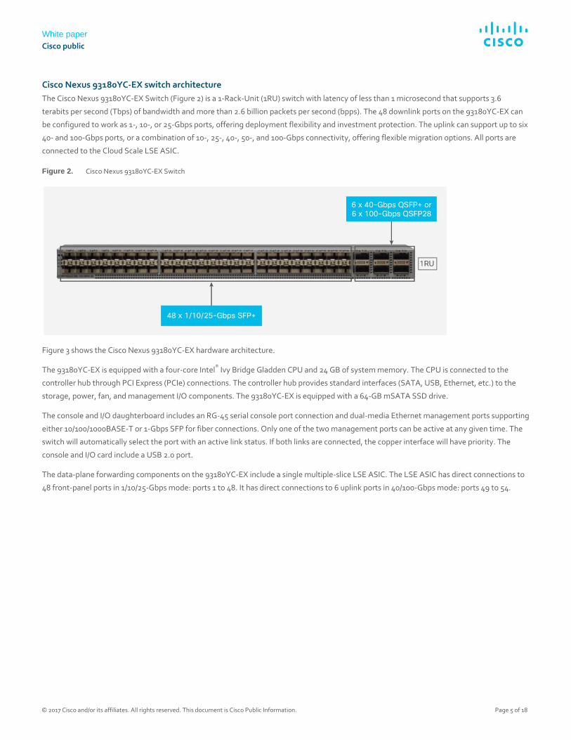
Cisco Nexus 93180YC-EX switch architecture
The Cisco Nexus 93180YC-EX Switch (Figure 2) is a 1-Rack-Unit (1RU) switch with latency of less than 1 microsecond that supports 3.6
terabits per second (Tbps) of bandwidth and more than 2.6 billion packets per second (bpps). The 48 downlink ports on the 93180YC-EX can
be configured to work as 1-, 10-, or 25-Gbps ports, offering deployment flexibility and investment protection. The uplink can support up to six
40- and 100-Gbps ports, or a combination of 10-, 25-, 40-, 50-, and 100-Gbps connectivity, offering flexible migration options. All ports are
connected to the Cloud Scale LSE ASIC.
Figure 2. Cisco Nexus 93180YC-EX Switch
Figure 3 shows the Cisco Nexus 93180YC-EX hardware architecture.
The 93180YC-EX is equipped with a four-core Intel® Ivy Bridge Gladden CPU and 24 GB of system memory. The CPU is connected to the
controller hub through PCI Express (PCIe) connections. The controller hub provides standard interfaces (SATA, USB, Ethernet, etc.) to the
storage, power, fan, and management I/O components. The 93180YC-EX is equipped with a 64-GB mSATA SSD drive.
The console and I/O daughterboard includes an RG-45 serial console port connection and dual-media Ethernet management ports supporting
either 10/100/1000BASE-T or 1-Gbps SFP for fiber connections. Only one of the two management ports can be active at any given time. The
switch will automatically select the port with an active link status. If both links are connected, the copper interface will have priority. The
console and I/O card include a USB 2.0 port.
The data-plane forwarding components on the 93180YC-EX include a single multiple-slice LSE ASIC. The LSE ASIC has direct connections to
48 front-panel ports in 1/10/25-Gbps mode: ports 1 to 48. It has direct connections to 6 uplink ports in 40/100-Gbps mode: ports 49 to 54.
White paper
Cisco public
© 2017 Cisco and/or its affiliates. All rights reserved. This document is Cisco Public Information. Page 6 of 18
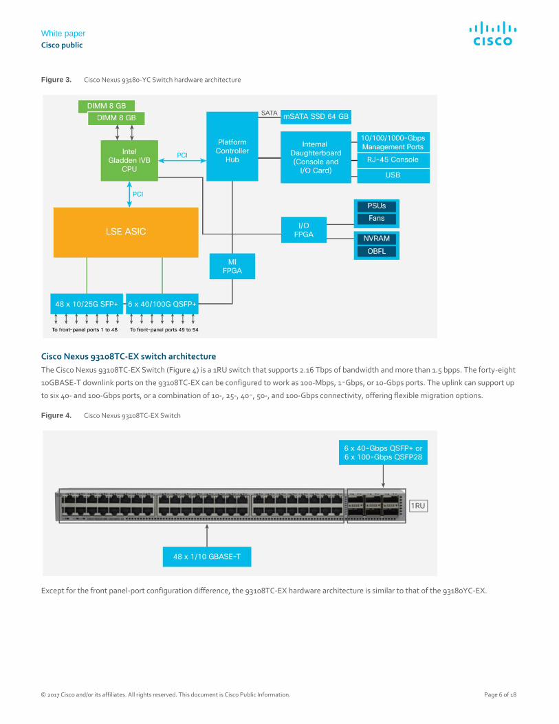
Figure 3. Cisco Nexus 93180-YC Switch hardware architecture
Cisco Nexus 93108TC-EX switch architecture
The Cisco Nexus 93108TC-EX Switch (Figure 4) is a 1RU switch that supports 2.16 Tbps of bandwidth and more than 1.5 bpps. The forty-eight
10GBASE-T downlink ports on the 93108TC-EX can be configured to work as 100-Mbps, 1‑Gbps, or 10-Gbps ports. The uplink can support up
to six 40- and 100-Gbps ports, or a combination of 10-, 25-, 40‑, 50-, and 100-Gbps connectivity, offering flexible migration options.
Figure 4. Cisco Nexus 93108TC-EX Switch
Except for the front panel-port configuration difference, the 93108TC-EX hardware architecture is similar to that of the 93180YC-EX.
White paper
Cisco public
© 2017 Cisco and/or its affiliates. All rights reserved. This document is Cisco Public Information. Page 7 of 18
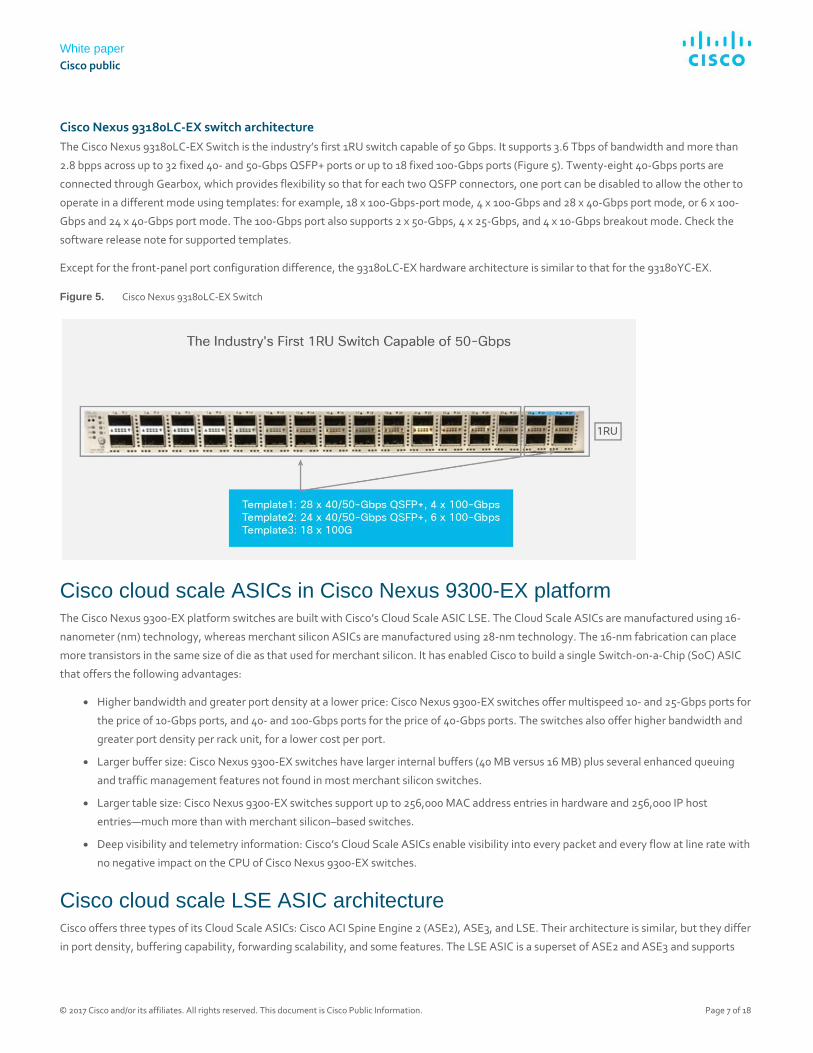
Cisco Nexus 93180LC-EX switch architecture
The Cisco Nexus 93180LC-EX Switch is the industry’s first 1RU switch capable of 50 Gbps. It supports 3.6 Tbps of bandwidth and more than
2.8 bpps across up to 32 fixed 40- and 50-Gbps QSFP+ ports or up to 18 fixed 100-Gbps ports (Figure 5). Twenty-eight 40-Gbps ports are
connected through Gearbox, which provides flexibility so that for each two QSFP connectors, one port can be disabled to allow the other to
operate in a different mode using templates: for example, 18 x 100-Gbps-port mode, 4 x 100-Gbps and 28 x 40-Gbps port mode, or 6 x 100-
Gbps and 24 x 40-Gbps port mode. The 100-Gbps port also supports 2 x 50-Gbps, 4 x 25-Gbps, and 4 x 10-Gbps breakout mode. Check the
software release note for supported templates.
Except for the front-panel port configuration difference, the 93180LC-EX hardware architecture is similar to that for the 93180YC-EX.
Figure 5. Cisco Nexus 93180LC-EX Switch
Cisco cloud scale ASICs in Cisco Nexus 9300-EX platform The Cisco Nexus 9300-EX platform switches are built with Cisco’s Cloud Scale ASIC LSE. The Cloud Scale ASICs are manufactured using 16-
nanometer (nm) technology, whereas merchant silicon ASICs are manufactured using 28-nm technology. The 16-nm fabrication can place
more transistors in the same size of die as that used for merchant silicon. It has enabled Cisco to build a single Switch-on-a-Chip (SoC) ASIC
that offers the following advantages:
● Higher bandwidth and greater port density at a lower price: Cisco Nexus 9300-EX switches offer multispeed 10- and 25-Gbps ports for
the price of 10-Gbps ports, and 40- and 100-Gbps ports for the price of 40-Gbps ports. The switches also offer higher bandwidth and
greater port density per rack unit, for a lower cost per port.
● Larger buffer size: Cisco Nexus 9300-EX switches have larger internal buffers (40 MB versus 16 MB) plus several enhanced queuing
and traffic management features not found in most merchant silicon switches.
● Larger table size: Cisco Nexus 9300-EX switches support up to 256,000 MAC address entries in hardware and 256,000 IP host
entries—much more than with merchant silicon–based switches.
● Deep visibility and telemetry information: Cisco’s Cloud Scale ASICs enable visibility into every packet and every flow at line rate with
no negative impact on the CPU of Cisco Nexus 9300-EX switches.
Cisco cloud scale LSE ASIC architecture Cisco offers three types of its Cloud Scale ASICs: Cisco ACI Spine Engine 2 (ASE2), ASE3, and LSE. Their architecture is similar, but they differ
in port density, buffering capability, forwarding scalability, and some features. The LSE ASIC is a superset of ASE2 and ASE3 and supports
White paper
Cisco public
© 2017 Cisco and/or its affiliates. All rights reserved. This document is Cisco Public Information. Page 8 of 18
Cisco ACI leaf switch and Fabric Extender (FEX) functions. Like the other Cloud Scale ASICs, the LSE uses a multiple-slice SOC design. The
Cisco Nexus 9300-EX platform switches are built with the LSE ASIC.
Each ASIC has three main components:
● Slice components: The slices make up the switching subsystems. They include multimode MAC addresses, packet parser, forwarding
lookup controller, I/O packet buffering, buffer accounting, output queuing, scheduling, and output rewrite components.
● I/O components: The I/O components consist of high-speed Serializer/Deserializer (SerDes) blocks. These vary based on the total
number of ports. They determine the total bandwidth capacity of the ASICs.
● Global components: The global components consist of the PCIe Generation 2 (Gen 2) controller for register and Enhanced Direct
Memory Access (EDMA) access and a set of point-to-multipoint wires to connect all the slices together. Components also include the
central statistics counter modules and modules to generate core and MAC address clocks.
The LSE ASIC is assembled with two slices, with each slice capable of supporting up to 800 Gbps of bandwidth, for a total of 1.6 Tbps at 1.25
GHz. Each slice has 40 ports independent of the speed or type of the ports. The port available speeds are 1, 10, 25, 40, 50, and 100 Gbps.
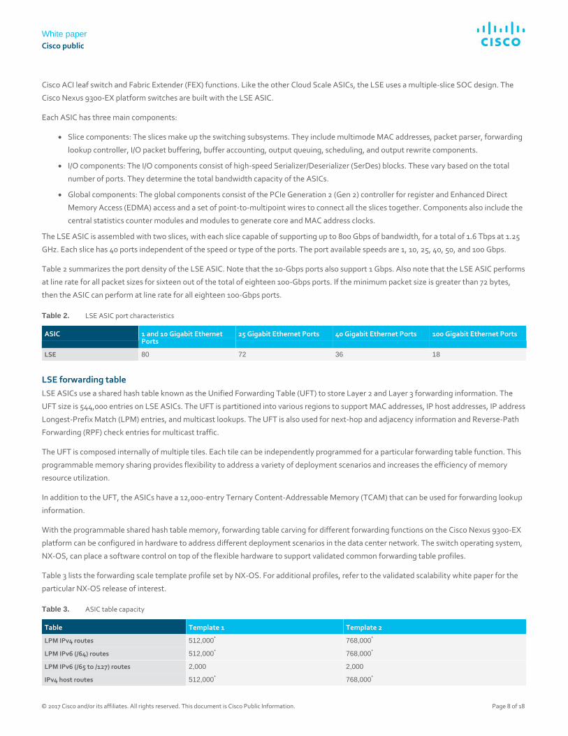
Table 2 summarizes the port density of the LSE ASIC. Note that the 10-Gbps ports also support 1 Gbps. Also note that the LSE ASIC performs
at line rate for all packet sizes for sixteen out of the total of eighteen 100-Gbps ports. If the minimum packet size is greater than 72 bytes,
then the ASIC can perform at line rate for all eighteen 100-Gbps ports.
Table 2. LSE ASIC port characteristics
ASIC 1 and 10 Gigabit Ethernet Ports
25 Gigabit Ethernet Ports 40 Gigabit Ethernet Ports 100 Gigabit Ethernet Ports
LSE 80 72 36 18
LSE forwarding table
LSE ASICs use a shared hash table known as the Unified Forwarding Table (UFT) to store Layer 2 and Layer 3 forwarding information. The
UFT size is 544,000 entries on LSE ASICs. The UFT is partitioned into various regions to support MAC addresses, IP host addresses, IP address
Longest-Prefix Match (LPM) entries, and multicast lookups. The UFT is also used for next-hop and adjacency information and Reverse-Path
Forwarding (RPF) check entries for multicast traffic.
The UFT is composed internally of multiple tiles. Each tile can be independently programmed for a particular forwarding table function. This
programmable memory sharing provides flexibility to address a variety of deployment scenarios and increases the efficiency of memory
resource utilization.
In addition to the UFT, the ASICs have a 12,000-entry Ternary Content-Addressable Memory (TCAM) that can be used for forwarding lookup
information.
With the programmable shared hash table memory, forwarding table carving for different forwarding functions on the Cisco Nexus 9300-EX
platform can be configured in hardware to address different deployment scenarios in the data center network. The switch operating system,
NX-OS, can place a software control on top of the flexible hardware to support validated common forwarding table profiles.
Table 3 lists the forwarding scale template profile set by NX-OS. For additional profiles, refer to the validated scalability white paper for the
particular NX-OS release of interest.
Table 3. ASIC table capacity
Table Template 1 Template 2
LPM IPv4 routes 512,000* 768,000*
LPM IPv6 (/64) routes 512,000* 768,000*
LPM IPv6 (/65 to /127) routes 2,000 2,000
IPv4 host routes 512,000* 768,000*
White paper
Cisco public
© 2017 Cisco and/or its affiliates. All rights reserved. This document is Cisco Public Information. Page 9 of 18
IPv6 host routes 24,000 24,000
Multicast 16,000 16,000
MAC addresses 96,000 16,000
* Shared entries
LSE buffer architecture
The slices in the LSE ASICs function as switching subsystems. Each slice has its own buffer memory, which is shared among all the ports on
this slice. Only ports within that slice can use the shared buffer space.
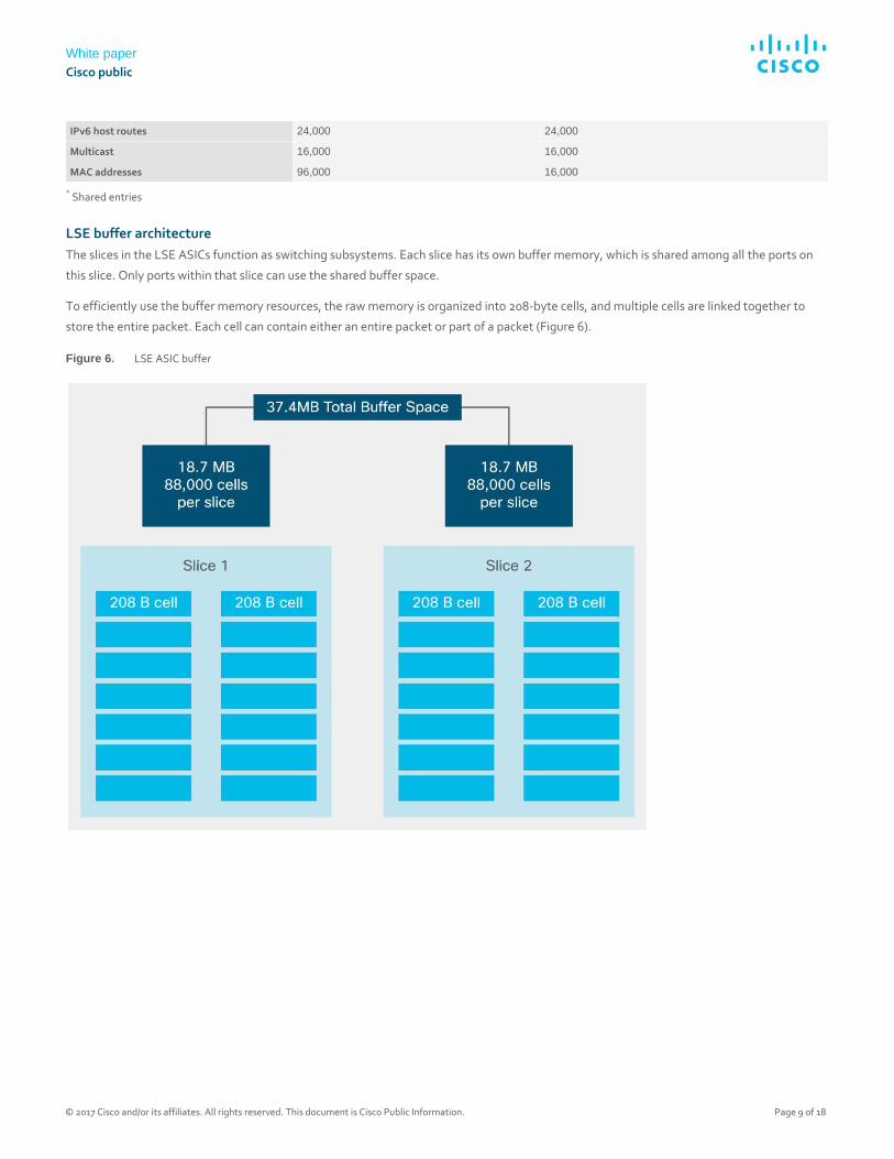
To efficiently use the buffer memory resources, the raw memory is organized into 208-byte cells, and multiple cells are linked together to
store the entire packet. Each cell can contain either an entire packet or part of a packet (Figure 6).
Figure 6. LSE ASIC buffer
White paper
Cisco public
© 2017 Cisco and/or its affiliates. All rights reserved. This document is Cisco Public Information. Page 10 of 18
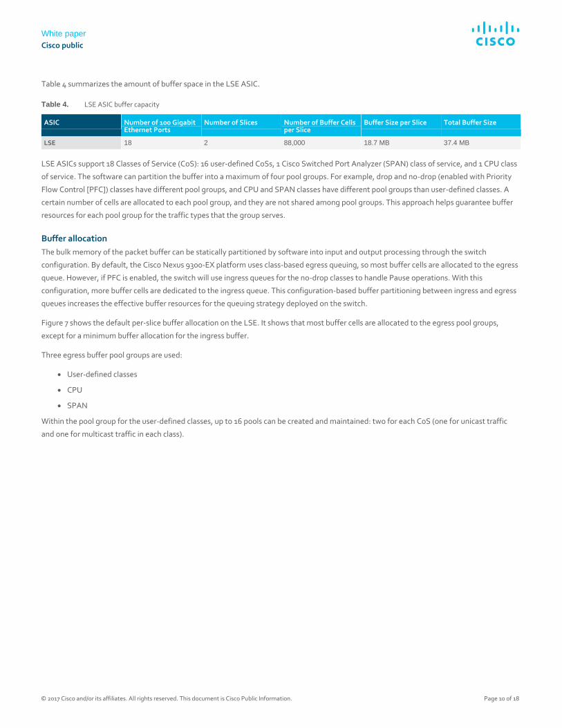
Table 4 summarizes the amount of buffer space in the LSE ASIC.
Table 4. LSE ASIC buffer capacity
ASIC Number of 100 Gigabit Ethernet Ports
Number of Slices Number of Buffer Cells per Slice
Buffer Size per Slice Total Buffer Size
LSE 18 2 88,000 18.7 MB 37.4 MB
LSE ASICs support 18 Classes of Service (CoS): 16 user-defined CoSs, 1 Cisco Switched Port Analyzer (SPAN) class of service, and 1 CPU class
of service. The software can partition the buffer into a maximum of four pool groups. For example, drop and no-drop (enabled with Priority
Flow Control [PFC]) classes have different pool groups, and CPU and SPAN classes have different pool groups than user-defined classes. A
certain number of cells are allocated to each pool group, and they are not shared among pool groups. This approach helps guarantee buffer
resources for each pool group for the traffic types that the group serves.
Buffer allocation
The bulk memory of the packet buffer can be statically partitioned by software into input and output processing through the switch
configuration. By default, the Cisco Nexus 9300-EX platform uses class-based egress queuing, so most buffer cells are allocated to the egress
queue. However, if PFC is enabled, the switch will use ingress queues for the no-drop classes to handle Pause operations. With this
configuration, more buffer cells are dedicated to the ingress queue. This configuration-based buffer partitioning between ingress and egress
queues increases the effective buffer resources for the queuing strategy deployed on the switch.
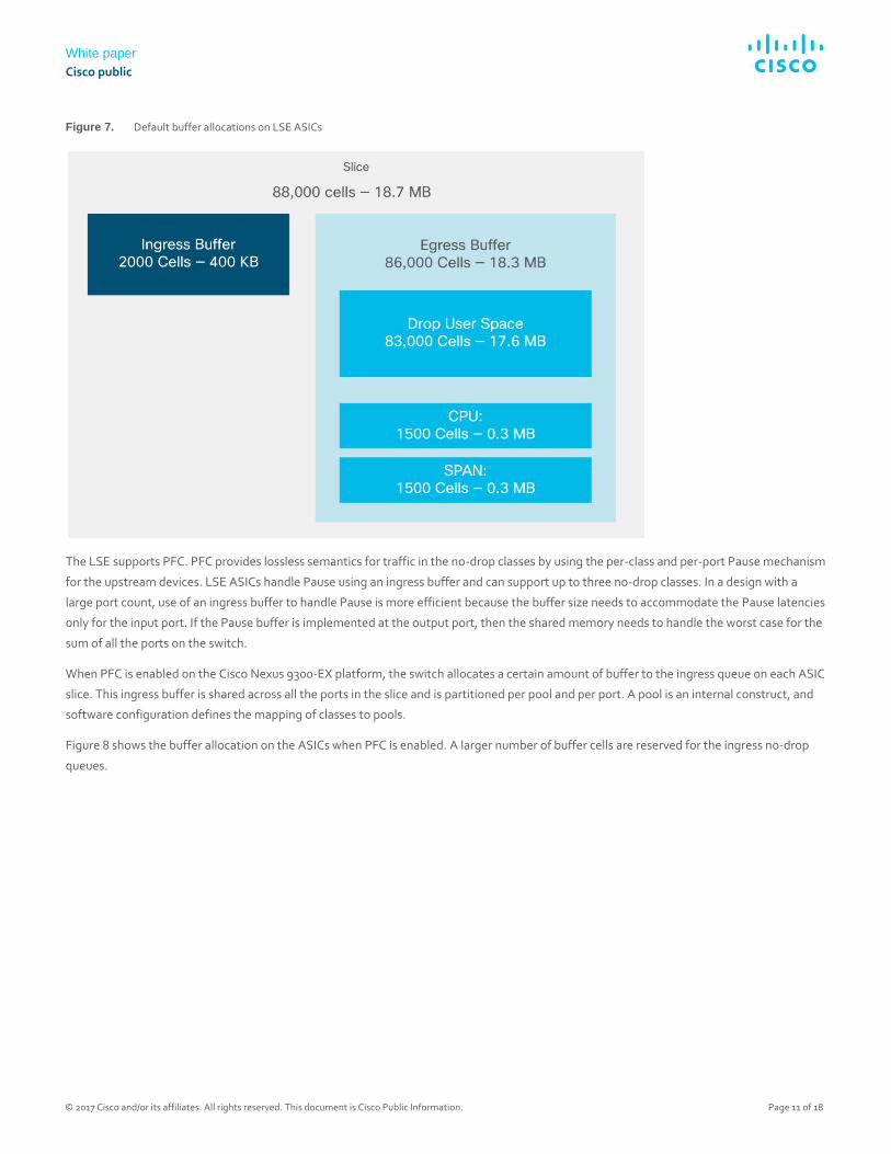
Figure 7 shows the default per-slice buffer allocation on the LSE. It shows that most buffer cells are allocated to the egress pool groups,
except for a minimum buffer allocation for the ingress buffer.
Three egress buffer pool groups are used:
● User-defined classes
● CPU
● SPAN
Within the pool group for the user-defined classes, up to 16 pools can be created and maintained: two for each CoS (one for unicast traffic
and one for multicast traffic in each class).
White paper
Cisco public
© 2017 Cisco and/or its affiliates. All rights reserved. This document is Cisco Public Information. Page 11 of 18
Figure 7. Default buffer allocations on LSE ASICs
The LSE supports PFC. PFC provides lossless semantics for traffic in the no-drop classes by using the per-class and per-port Pause mechanism
for the upstream devices. LSE ASICs handle Pause using an ingress buffer and can support up to three no-drop classes. In a design with a
large port count, use of an ingress buffer to handle Pause is more efficient because the buffer size needs to accommodate the Pause latencies
only for the input port. If the Pause buffer is implemented at the output port, then the shared memory needs to handle the worst case for the
sum of all the ports on the switch.
When PFC is enabled on the Cisco Nexus 9300-EX platform, the switch allocates a certain amount of buffer to the ingress queue on each ASIC
slice. This ingress buffer is shared across all the ports in the slice and is partitioned per pool and per port. A pool is an internal construct, and
software configuration defines the mapping of classes to pools.
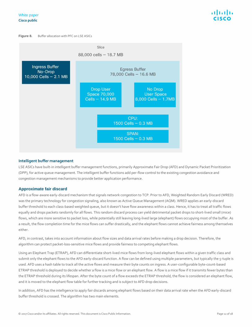
Figure 8 shows the buffer allocation on the ASICs when PFC is enabled. A larger number of buffer cells are reserved for the ingress no-drop
queues.
White paper
Cisco public
© 2017 Cisco and/or its affiliates. All rights reserved. This document is Cisco Public Information. Page 12 of 18
Figure 8. Buffer allocation with PFC on LSE ASICs
Intelligent buffer management
LSE ASICs have built-in intelligent buffer management functions, primarily Approximate Fair Drop (AFD) and Dynamic Packet Prioritization
(DPP), for active queue management. The intelligent buffer functions add per-flow control to the existing congestion avoidance and
congestion management mechanisms to provide better application performance.
Approximate fair discard
AFD is a flow-aware early-discard mechanism that signals network congestion to TCP. Prior to AFD, Weighted Random Early Discard (WRED)
was the primary technology for congestion signaling, also known as Active Queue Management (AQM). WRED applies an early-discard
buffer threshold to each class-based weighted queue, but it doesn’t have flow awareness within a class. Hence, it has to treat all traffic flows
equally and drops packets randomly for all flows. This random discard process can yield detrimental packet drops to short-lived small (mice)
flows, which are more sensitive to packet loss, while potentially still leaving long-lived large (elephant) flows occupying most of the buffer. As
a result, the flow completion time for the mice flows can suffer drastically, and the elephant flows cannot achieve fairness among themselves
either.
AFD, in contrast, takes into account information about flow sizes and data arrival rates before making a drop decision. Therefore, the
algorithm can protect packet-loss-sensitive mice flows and provide fairness to competing elephant flows.
Using an Elephant Trap (ETRAP), AFD can differentiate short-lived mice flows from long-lived elephant flows within a given traffic class and
submit only the elephant flows to the AFD early-discard function. A flow can be defined using multiple parameters, but typically the 5-tuple is
used. AFD uses a hash table to track all the active flows and measure their byte counts on ingress. A user-configurable byte-count-based
ETRAP threshold is deployed to decide whether a flow is a mice flow or an elephant flow. A flow is a mice flow if it transmits fewer bytes than
the ETRAP threshold during its lifespan. After the byte count of a flow exceeds the ETRAP threshold, the flow is considered an elephant flow,
and it is moved to the elephant flow table for further tracking and is subject to AFD drop decisions.
In addition, AFD has the intelligence to apply fair discards among elephant flows based on their data arrival rate when the AFD early-discard
buffer threshold is crossed. The algorithm has two main elements.
White paper
Cisco public
© 2017 Cisco and/or its affiliates. All rights reserved. This document is Cisco Public Information. Page 13 of 18
One element is rate measurement: ETRAP measures the arrival rate of each flow in the elephant flow table on the ingress port, and the
measured arrival rate is carried in the packet header when packets are internally forwarded to the egress port.
The other main element of AFD is the fair-rate calculation: the AFD algorithm dynamically computes a per-flow fair rate on an egress port
using a feedback mechanism based on the egress port queue occupancy. When a packet of an elephant flow enters the egress port queue,
the AFD algorithm compares the measured arrival rate of the flow with the computed fair share. If the arrival rate of an elephant flow is less
than the per-flow fair rate, the packet is not dropped. However, if the arrival rate exceeds the computed per-flow fair rate on the egress port,
packets will be dropped from that flow in proportion to the amount that the flow exceeds the fair rate. The drop probability is computed
using the fair rate and the measured flow rate. As a result, all elephant flows achieve the fair rate. The AFD parameters for the output queues
are configured using profiles. The profile, as with WRED, can be configured to mark a packet with Explicit Congestion Notification (ECN)
instead of dropping it.
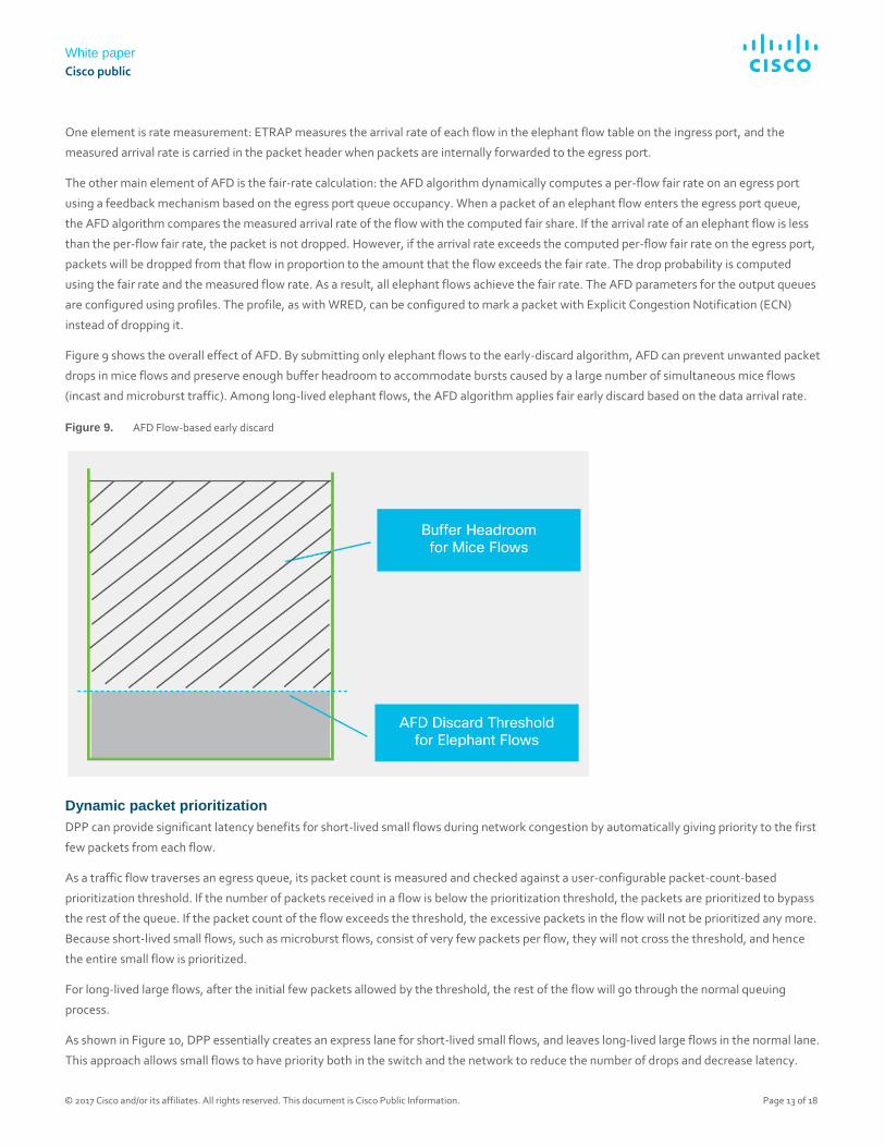
Figure 9 shows the overall effect of AFD. By submitting only elephant flows to the early-discard algorithm, AFD can prevent unwanted packet
drops in mice flows and preserve enough buffer headroom to accommodate bursts caused by a large number of simultaneous mice flows
(incast and microburst traffic). Among long-lived elephant flows, the AFD algorithm applies fair early discard based on the data arrival rate.
Figure 9. AFD Flow-based early discard
Dynamic packet prioritization
DPP can provide significant latency benefits for short-lived small flows during network congestion by automatically giving priority to the first
few packets from each flow.
As a traffic flow traverses an egress queue, its packet count is measured and checked against a user-configurable packet-count-based
prioritization threshold. If the number of packets received in a flow is below the prioritization threshold, the packets are prioritized to bypass
the rest of the queue. If the packet count of the flow exceeds the threshold, the excessive packets in the flow will not be prioritized any more.
Because short-lived small flows, such as microburst flows, consist of very few packets per flow, they will not cross the threshold, and hence
the entire small flow is prioritized.
For long-lived large flows, after the initial few packets allowed by the threshold, the rest of the flow will go through the normal queuing
process.
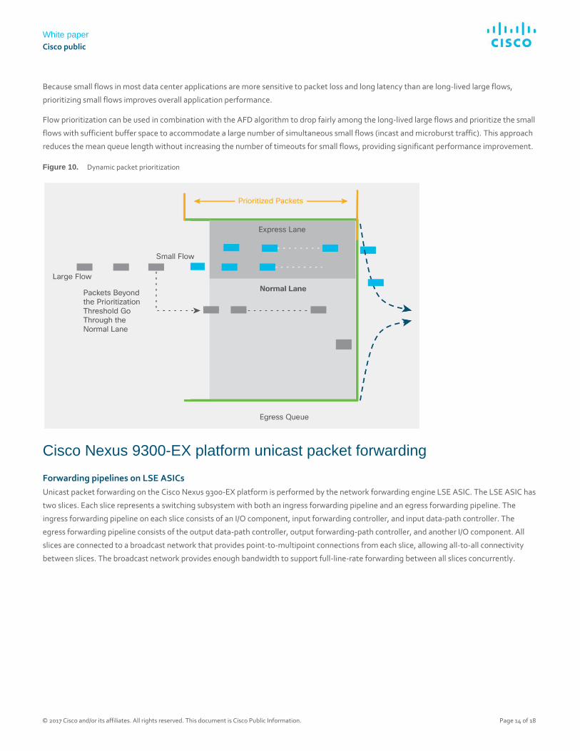
As shown in Figure 10, DPP essentially creates an express lane for short-lived small flows, and leaves long-lived large flows in the normal lane.
This approach allows small flows to have priority both in the switch and the network to reduce the number of drops and decrease latency.
White paper
Cisco public
© 2017 Cisco and/or its affiliates. All rights reserved. This document is Cisco Public Information. Page 14 of 18
Because small flows in most data center applications are more sensitive to packet loss and long latency than are long-lived large flows,
prioritizing small flows improves overall application performance.
Flow prioritization can be used in combination with the AFD algorithm to drop fairly among the long-lived large flows and prioritize the small
flows with sufficient buffer space to accommodate a large number of simultaneous small flows (incast and microburst traffic). This approach
reduces the mean queue length without increasing the number of timeouts for small flows, providing significant performance improvement.
Figure 10. Dynamic packet prioritization
Cisco Nexus 9300-EX platform unicast packet forwarding
Forwarding pipelines on LSE ASICs
Unicast packet forwarding on the Cisco Nexus 9300-EX platform is performed by the network forwarding engine LSE ASIC. The LSE ASIC has
two slices. Each slice represents a switching subsystem with both an ingress forwarding pipeline and an egress forwarding pipeline. The
ingress forwarding pipeline on each slice consists of an I/O component, input forwarding controller, and input data-path controller. The
egress forwarding pipeline consists of the output data-path controller, output forwarding-path controller, and another I/O component. All
slices are connected to a broadcast network that provides point-to-multipoint connections from each slice, allowing all-to-all connectivity
between slices. The broadcast network provides enough bandwidth to support full-line-rate forwarding between all slices concurrently.
White paper
Cisco public
© 2017 Cisco and/or its affiliates. All rights reserved. This document is Cisco Public Information. Page 15 of 18
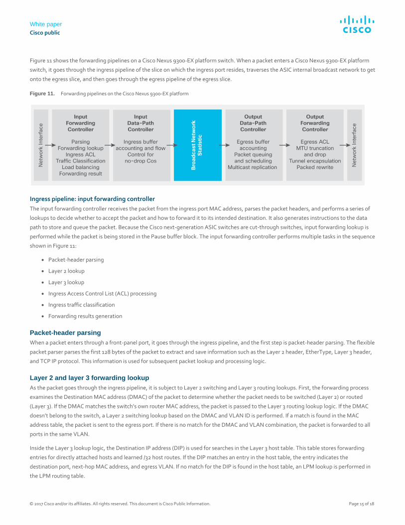
Figure 11 shows the forwarding pipelines on a Cisco Nexus 9300-EX platform switch. When a packet enters a Cisco Nexus 9300-EX platform
switch, it goes through the ingress pipeline of the slice on which the ingress port resides, traverses the ASIC internal broadcast network to get
onto the egress slice, and then goes through the egress pipeline of the egress slice.
Figure 11. Forwarding pipelines on the Cisco Nexus 9300-EX platform
Ingress pipeline: input forwarding controller
The input forwarding controller receives the packet from the ingress port MAC address, parses the packet headers, and performs a series of
lookups to decide whether to accept the packet and how to forward it to its intended destination. It also generates instructions to the data
path to store and queue the packet. Because the Cisco next-generation ASIC switches are cut-through switches, input forwarding lookup is
performed while the packet is being stored in the Pause buffer block. The input forwarding controller performs multiple tasks in the sequence
shown in Figure 11:
● Packet-header parsing
● Layer 2 lookup
● Layer 3 lookup
● Ingress Access Control List (ACL) processing
● Ingress traffic classification
● Forwarding results generation
Packet-header parsing
When a packet enters through a front-panel port, it goes through the ingress pipeline, and the first step is packet-header parsing. The flexible
packet parser parses the first 128 bytes of the packet to extract and save information such as the Layer 2 header, EtherType, Layer 3 header,
and TCP IP protocol. This information is used for subsequent packet lookup and processing logic.
Layer 2 and layer 3 forwarding lookup
As the packet goes through the ingress pipeline, it is subject to Layer 2 switching and Layer 3 routing lookups. First, the forwarding process
examines the Destination MAC address (DMAC) of the packet to determine whether the packet needs to be switched (Layer 2) or routed
(Layer 3). If the DMAC matches the switch’s own router MAC address, the packet is passed to the Layer 3 routing lookup logic. If the DMAC
doesn’t belong to the switch, a Layer 2 switching lookup based on the DMAC and VLAN ID is performed. If a match is found in the MAC
address table, the packet is sent to the egress port. If there is no match for the DMAC and VLAN combination, the packet is forwarded to all
ports in the same VLAN.
Inside the Layer 3 lookup logic, the Destination IP address (DIP) is used for searches in the Layer 3 host table. This table stores forwarding
entries for directly attached hosts and learned /32 host routes. If the DIP matches an entry in the host table, the entry indicates the
destination port, next-hop MAC address, and egress VLAN. If no match for the DIP is found in the host table, an LPM lookup is performed in
the LPM routing table.
White paper
Cisco public
© 2017 Cisco and/or its affiliates. All rights reserved. This document is Cisco Public Information. Page 16 of 18
Ingress ACL processing
In addition to forwarding lookup processing, the packet undergoes ingress ACL processing. The ACL TCAM is checked for ingress ACL
matches. Each ASIC has an ingress ACL TCAM table of 4000 entries per slice to support system internal ACLs and user-defined ingress ACLs.
These ACLs include Port ACLs (PACLs), Routed ACLs (RACLs), and VLAN ACLs (VACLs). ACL entries are localized to the slice and are
programmed only where needed. This approach makes the best use of the ACL TCAM in the Cisco Nexus 9300-EX platform switch.
Ingress traffic classification
Cisco Nexus 9300-EX platform switches support ingress traffic classification. On an ingress interface, traffic can be classified based on the
address field, IEEE 802.1q CoS, and IP precedence or Differentiated Services Code Point (DSCP) in the packet header. The classified traffic
can be assigned to one of the eight Quality-of-Service (QoS) groups. The QoS groups internally identify the traffic classes that are used for
subsequent QoS processes as packets traverse the system.
Ingress forwarding result generation
The final step in the ingress forwarding pipeline is to collect all the forwarding metadata generated earlier in the pipeline and pass it to the
downstream blocks through the data path. A 64-byte internal header is stored along with the incoming packet in the packet buffer. This
internal header includes 16 bytes of iETH (internal communication protocol) header information, which is added on top of the packet when
the packet is transferred to the output data-path controller through the broadcast network. This 16-byte iETH header is stripped off when the
packet exits the front-panel port. The other 48 bytes of internal header space are used only to pass metadata from the input forwarding
queue to the output forwarding queue and are consumed by the output forwarding engine.
Ingress pipeline: input data-path controller
The input data-path controller performs ingress accounting functions, admission functions, and flow control for the no-drop CoS. The ingress
admission-control mechanism determines whether a packet should be admitted into memory. This decision is based on the amount of buffer
memory available and the amount of buffer space already used by the ingress port and traffic class. The input data-path controller forwards
the packet to the output data-path controller through the broadcast network.
Broadcast network and central statistics module
The broadcast network is a set of point-to-multipoint wires that allows connectivity between all slices on the ASIC. The input data-path
controller has a point-to-multipoint connection to the output data-path controllers on all slices, including its own slice. The central statistics
module is connected to the broadcast network. The central statistics module provides packet, byte, and atomic counter statistics.
Egress pipeline: output data-path controller
The output data-path controller performs egress buffer accounting, packet queuing, scheduling, and multicast replication. All ports
dynamically share the egress buffer resource. The details of dynamic buffer allocation are described earlier in this document.
The output data-path controller also performs packet shaping. Following the design principle of simplicity and efficiency, the Cisco Nexus
9300-EX platform uses a simple egress queuing architecture. In the event of egress port congestion, packets are directly queued in the buffer
of the egress slice. There are no Virtual output Queues (VoQs) on the ingress slice. This approach greatly simplifies system buffer
management and queuing implementation.
White paper
Cisco public
© 2017 Cisco and/or its affiliates. All rights reserved. This document is Cisco Public Information. Page 17 of 18
A Cisco Nexus 9300-EX switch can support up to 10 traffic classes on egress, 8 user-defined classes identified by QoS group IDs, a CPU control
traffic class, and a SPAN traffic class. Each user-defined class can have a unicast queue and a multicast queue per egress port. This approach
helps ensure that no single port can consume more than its fair share of the buffer memory and cause buffer starvation for other ports.
Egress pipeline: output forwarding controller
The output forwarding controller receives the input packet and associated metadata from the buffer manager and is responsible for all
packet rewrite operations and application of egress policy. It extracts internal header information and various packet-header fields from the
packet, performs a series of lookups, and generates the rewrite instructions.
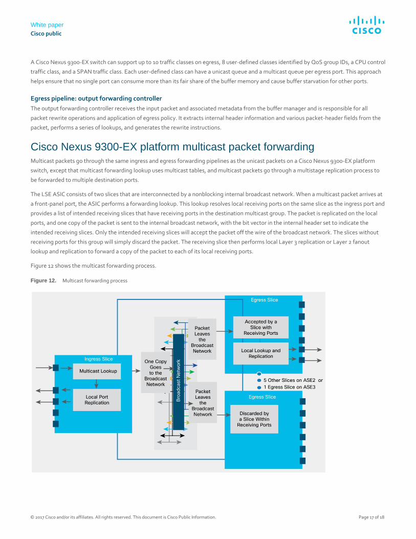
Cisco Nexus 9300-EX platform multicast packet forwarding Multicast packets go through the same ingress and egress forwarding pipelines as the unicast packets on a Cisco Nexus 9300-EX platform
switch, except that multicast forwarding lookup uses multicast tables, and multicast packets go through a multistage replication process to
be forwarded to multiple destination ports.
The LSE ASIC consists of two slices that are interconnected by a nonblocking internal broadcast network. When a multicast packet arrives at
a front-panel port, the ASIC performs a forwarding lookup. This lookup resolves local receiving ports on the same slice as the ingress port and
provides a list of intended receiving slices that have receiving ports in the destination multicast group. The packet is replicated on the local
ports, and one copy of the packet is sent to the internal broadcast network, with the bit vector in the internal header set to indicate the
intended receiving slices. Only the intended receiving slices will accept the packet off the wire of the broadcast network. The slices without
receiving ports for this group will simply discard the packet. The receiving slice then performs local Layer 3 replication or Layer 2 fanout
lookup and replication to forward a copy of the packet to each of its local receiving ports.
Figure 12 shows the multicast forwarding process.
Figure 12. Multicast forwarding process
White paper
Cisco public
© 2017 Cisco and/or its affiliates. All rights reserved. This document is Cisco Public Information. Page 18 of 18
Conclusion Cisco Nexus 9300-EX platform switches are the next generation of fixed Cisco Nexus 9000 Series Switches. The new platform, based on
Cisco’s Cloud Scale ASIC, supports cost-effective cloud-scale deployments, an increased number of endpoints, and cloud services with wire-
rate security and telemetry. The platform is built on a modern system architecture designed to provide high performance to meet the
evolving needs of highly scalable data centers and growing enterprises. Cisco Nexus 9300-EX platform switches offer a variety of interface
options to transparently migrate existing data centers from 100-Mbps, 1-Gbps, and 10-Gbps speeds to 25 Gbps at the server, and from 10-
and 40-Gbps speeds to 50 and 100 Gbps at the aggregation layer. The platform can collect comprehensive Cisco Tetration Analytics
telemetry information at line rate across all the ports without adding any latency to the packets or negatively affecting switch performance.
For more information For more information about the Cisco Nexus 9000 Series Switches, see the detailed product information at the product homepage at
http://www.cisco.com/c/en/us/products/switches/nexus-9000-series-switches/index.html.
Printed in USAs C11-739134-00 06/17