Embed Size (px)
Citation preview
Americas HeadquartersCisco Systems, Inc.170 West Tasman DriveSan Jose, CA 95134-1706 USAhttp://www.cisco.comTel: 408 526-4000
800 553-NETS (6387)Fax: 408 527-0883
Cisco Unified Serviceability Administration GuideFor Cisco Unified CCX and Cisco Unified IP IVR Release 8.0(1)
February 2010

THE SPECIFICATIONS AND INFORMATION REGARDING THE PRODUCTS IN THIS MANUAL ARE SUBJECT TO CHANGE WITHOUT NOTICE. ALL STATEMENTS, INFORMATION, AND RECOMMENDATIONS IN THIS MANUAL ARE BELIEVED TO BE ACCURATE BUT ARE PRESENTED WITHOUT WARRANTY OF ANY KIND, EXPRESS OR IMPLIED. USERS MUST TAKE FULL RESPONSIBILITY FOR THEIR APPLICATION OF ANY PRODUCTS.
THE SOFTWARE LICENSE AND LIMITED WARRANTY FOR THE ACCOMPANYING PRODUCT ARE SET FORTH IN THE INFORMATION PACKET THAT SHIPPED WITH THE PRODUCT AND ARE INCORPORATED HEREIN BY THIS REFERENCE. IF YOU ARE UNABLE TO LOCATE THE SOFTWARE LICENSE OR LIMITED WARRANTY, CONTACT YOUR CISCO REPRESENTATIVE FOR A COPY.
The Cisco implementation of TCP header compression is an adaptation of a program developed by the University of California, Berkeley (UCB) as part of UCB’s public domain version of the UNIX operating system. All rights reserved. Copyright © 1981, Regents of the University of California.
NOTWITHSTANDING ANY OTHER WARRANTY HEREIN, ALL DOCUMENT FILES AND SOFTWARE OF THESE SUPPLIERS ARE PROVIDED “AS IS” WITH ALL FAULTS. CISCO AND THE ABOVE-NAMED SUPPLIERS DISCLAIM ALL WARRANTIES, EXPRESSED OR IMPLIED, INCLUDING, WITHOUT LIMITATION, THOSE OF MERCHANTABILITY, FITNESS FOR A PARTICULAR PURPOSE AND NONINFRINGEMENT OR ARISING FROM A COURSE OF DEALING, USAGE, OR TRADE PRACTICE.
IN NO EVENT SHALL CISCO OR ITS SUPPLIERS BE LIABLE FOR ANY INDIRECT, SPECIAL, CONSEQUENTIAL, OR INCIDENTAL DAMAGES, INCLUDING, WITHOUT LIMITATION, LOST PROFITS OR LOSS OR DAMAGE TO DATA ARISING OUT OF THE USE OR INABILITY TO USE THIS MANUAL, EVEN IF CISCO OR ITS SUPPLIERS HAVE BEEN ADVISED OF THE POSSIBILITY OF SUCH DAMAGES.
CCDE, CCENT, CCSI, Cisco Eos, Cisco Explorer, Cisco HealthPresence, Cisco IronPort, the Cisco logo, Cisco Nurse Connect, Cisco Pulse, Cisco SensorBase, Cisco StackPower, Cisco StadiumVision, Cisco TelePresence, Cisco TrustSec, Cisco Unified Computing System, Cisco WebEx, DCE, Flip Channels, Flip for Good, Flip Mino, Flipshare (Design), Flip Ultra, Flip Video, Flip Video (Design), Instant Broadband, and Welcome to the Human Network are trademarks; Changing the Way We Work, Live, Play, and Learn, Cisco Capital, Cisco Capital (Design), Cisco:Financed (Stylized), Cisco Store, Flip Gift Card, and One Million Acts of Green are service marks; and Access Registrar, Aironet, AllTouch, AsyncOS, Bringing the Meeting To You, Catalyst, CCDA, CCDP, CCIE, CCIP, CCNA, CCNP, CCSP, CCVP, Cisco, the Cisco Certified Internetwork Expert logo, Cisco IOS, Cisco Lumin, Cisco Nexus, Cisco Press, Cisco Systems, Cisco Systems Capital, the Cisco Systems logo, Cisco Unity, Collaboration Without Limitation, Continuum, EtherFast, EtherSwitch, Event Center, Explorer, Follow Me Browsing, GainMaker, iLYNX, IOS, iPhone, IronPort, the IronPort logo, Laser Link, LightStream, Linksys, MeetingPlace, MeetingPlace Chime Sound, MGX, Networkers, Networking Academy, PCNow, PIX, PowerKEY, PowerPanels, PowerTV, PowerTV (Design), PowerVu, Prisma, ProConnect, ROSA, SenderBase, SMARTnet, Spectrum Expert, StackWise, WebEx, and the WebEx logo are registered trademarks of Cisco and/or its affiliates in the United States and certain other countries.
All other trademarks mentioned in this document or website are the property of their respective owners. The use of the word partner does not imply a partnership relationship between Cisco and any other company. (1002R)
Cisco Unified Serviceability Administration Guide for Cisco Unifed CCX and Cisco Unified IP IVR Copyright © 2010 Cisco Systems, Inc. All rights reserved.
Cisco
C O N T E N T S
Preface ix
P A R T 1 Cisco Unified Serviceability
C H A P T E R 1 Understanding Cisco Unified Serviceability 1-1
Cisco Unified Serviceability Overview 1-1
Reporting and Monitoring Tools 1-2
Remote Serviceability Tools 1-2
Customized Log-on Message 1-3
Browser Support 1-3
Where to Find More Information 1-3
C H A P T E R 2 Using Cisco Unified Serviceability 2-1
Accessing Cisco Unified Serviceability 2-1
Installing the Server Certificate 2-2
HTTPS Overview for Internet Explorer 2-2
Installing the Certificate with Internet Explorer 6 2-3
Installing the Certificate with Internet Explorer 7 2-4
Using the Cisco Unified Serviceability Interface 2-5
Using Accessibility Features 2-6
Where to Find More Information 2-7
P A R T 2 Alarms
C H A P T E R 3 Understanding Alarms 3-1
Understanding Alarms 3-1
Alarm Configuration 3-2
Alarm Definitions 3-2
Viewing Alarm Information 3-3
Alarm Configuration Checklist 3-3
Where to Find More Information 3-4
iiiUnified Serviceability Administration Guide for Cisco Unifed CCX Release 8.0(1)
Contents
C H A P T E R 4 Configuring Alarms 4-1
Configuring an Alarm for a Service 4-1
Service Groups in Alarm Configuration 4-3
Alarm Configuration Settings 4-3
Where to Find More Information 4-5
C H A P T E R 5 Viewing and Updating Alarm Definitions 5-1
Viewing Alarm Definitions and Adding User-Defined Descriptions 5-1
System Alarm Catalog Descriptions 5-2
Where to Find More Information 5-3
P A R T 3 Trace
C H A P T E R 6 Understanding Trace 6-1
Understanding Trace 6-1
Trace Configuration 6-1
Troubleshooting Trace Settings 6-2
Trace Collection 6-2
Trace Configuration and Collection Checklist 6-3
Where to Find More Information 6-4
C H A P T E R 7 Configuring Trace 7-1
Configuring Trace Parameters 7-1
Service Groups in Trace Configuration 7-3
Debug Trace Level Settings 7-4
Trace Field Descriptions 7-5
Cisco Database Layer Monitor Trace Fields 7-5
Cisco RIS Data Collector Trace Fields 7-6
Trace Output Settings Descriptions and Defaults 7-6
Where to Find More Information 7-7
C H A P T E R 8 Configuring Troubleshooting Trace Settings 8-1
Where to Find More Information 8-2
P A R T 4 Tools
ivCisco Unified Serviceability Administration Guide for Cisco Unifed CCX Release 8.0(1)
Contents
C H A P T E R 9 Understanding Services 9-1
Feature Services 9-1
Database and Admin Services 9-2
Performance and Monitoring Services 9-2
Directory Services 9-2
Network Services 9-2
Performance and Monitoring Services 9-3
Backup and Restore Services 9-4
System Services 9-4
Platform Services 9-5
Security Services 9-6
DB Services 9-6
SOAP Services 9-6
Service Activation 9-7
Control Center 9-7
Services Configuration Checklist 9-8
Where to Find More Information 9-8
C H A P T E R 10 Understanding Serviceability Reports Archive 10-1
Serviceability Reporter Service Parameters 10-2
Server Statistics Report 10-2
Alert Summary Report 10-4
Serviceability Reports Archive Configuration Checklist 10-6
Where to Find More Information 10-6
C H A P T E R 11 Configuring Services 11-1
Activating and Deactivating Feature Services 11-1
Cluster Service Activation Recommendations 11-2
Starting, Stopping, Restarting, and Refreshing Status of Services in Control Center 11-3
Using a Command Line Interface to Start and Stop Services 11-4
Where to Find More Information 11-4
C H A P T E R 12 Configuring Serviceability Reports Archive 12-1
Where to Find More Information 12-2
C H A P T E R 13 Configuring the Audit Log 13-1
Understanding Audit Logging 13-1
vCisco Unified Serviceability Administration Guide for Cisco Unifed CCX Release 8.0(1)
Contents
Configuring the Audit Log 13-2
Audit Log Configuration Settings 13-2
Where to Find More Information 13-4
P A R T 5 Simple Network Management Protocol (SNMP)
C H A P T E R 14 Understanding Simple Network Management Protocol 14-1
Simple Network Management Protocol Support 14-1
SNMP Basics 14-1
SNMP Master Agent and Subagents 14-2
SNMP Configuration Requirements 14-2
SNMP Version 1 Support 14-2
SNMP Version 2c Support 14-3
SNMP Version 3 Support 14-3
SNMP Services 14-3
SNMP Community Strings and Users 14-4
SNMP Traps and Informs 14-4
SNMP Management Information Base (MIB) 14-5
SNMP Trace Configuration 14-9
SNMP Configuration Checklist 14-9
Where to Find More Information 14-10
C H A P T E R 15 Configuring SNMP V1/V2c 15-1
Finding a Community String 15-1
Configuring a Community String 15-2
Community String Configuration Settings 15-3
Deleting a Community String 15-4
SNMP Notification Destination 15-5
Finding a Notification Destination for SNMP V1/V2c 15-5
Configuring a Notification Destination for SNMP V1/V2c 15-6
Notification Destination Configuration Settings for SNMP V1/V2c 15-7
Deleting a Notification Destination for SNMP V1/V2c 15-8
Where to Find More Information 15-8
C H A P T E R 16 Configuring SNMP V3 16-1
Finding the SNMP User 16-1
Configuring the SNMP User 16-2
viCisco Unified Serviceability Administration Guide for Cisco Unifed CCX Release 8.0(1)

Contents
SNMP User Configuration Settings 16-3
Deleting the SNMP User 16-4
SNMP Notification Destination 16-5
Finding a Notification Destination for SNMP V3 16-5
Configuring a Notification Destination for SNMP V3 16-6
Notification Destination Configuration Settings for SNMP V3 16-7
Deleting a Notification Destination for SNMP V3 16-8
Where to Find More Information 16-8
C H A P T E R 17 Configuring SNMP System Group 17-1
Configuring the MIB2 System Group 17-1
MIB2 System Group Configuration Settings 17-2
Where to Find More Information 17-2
C H A P T E R 18 Configuring SNMP Trap Parameters 18-1
Configuring CISCO-SYSLOG-MIB Trap Parameters 18-1
Where to Find More Information 18-1
I N D E X
viiCisco Unified Serviceability Administration Guide for Cisco Unifed CCX Release 8.0(1)

Contents
viiiCisco Unified Serviceability Administration Guide for Cisco Unifed CCX Release 8.0(1)
Preface
This preface describes the purpose, audience, organization, and conventions of this guide, and provides information on how to obtain related documentation.
Note Cisco Unified Contact Center Express and Cisco Unified IP IVR will be referred to as Unified CCX in the rest of this document.
The preface covers these topics:
• Purpose, page ix
• Audience, page x
• Organization, page x
• Related Documentation, page xi
• Conventions, page xi
• Obtaining Documentation, Obtaining Support, and Security Guidelines, page xii
PurposeThe Cisco Unified Serviceability Administration Guide provides description and procedures for:
• Configuring alarms and traces for platform components and
• SNMP for platform and Unified CCX components
through Cisco Unified Serviceability web interface of Unified CCX 8.0(1).
Note For configuration of alarms and traces for Unified CCX components, see Cisco Unified CCX Serviceability Administration Guide.
Use this guide with the documentation for your configuration:
Cisco Unified CCX Cisco Unified CCX Serviceability Administration Guide and Cisco Unified CCX Real-Time Monitoring Tool Administration Guide.
ixCisco Unified Serviceability Administration Guide for Cisco Unifed CCX Release 8.0(1)
Preface
These documents provide the following information:
• Cisco Unified CCX Serviceability Administration Guide—This document provides description and procedures for configuring alarms, traces, service parameters, performance configuration, and logging through Unified CCX Serviceability.
• Cisco Unified CCX Real-Time Monitoring Tool Administration Guide—This document describes how to use RTMT, a tool that allows you to monitor many aspects of the system (critical services, alerts, performance counters, and so on).
Tip For Cisco Unified CCX, you must perform serviceability-related tasks in both Cisco Unified Serviceability and Cisco Unified CCX Serviceability; for example, you may need to start and stop services, configure alarms and traces in both applications to troubleshoot a problem.
AudienceThe Cisco Unified Serviceability Administration Guide assists administrators that configure, troubleshoot, and support Cisco Unified CCX. This guide requires knowledge of telephony and IP networking technology.
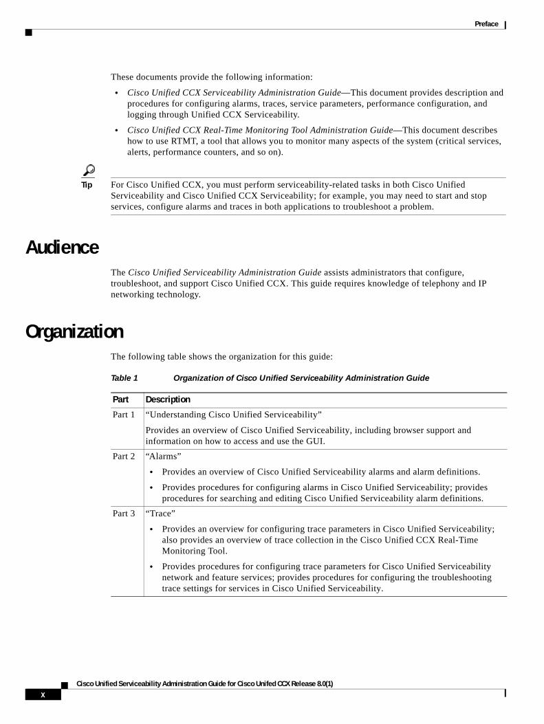
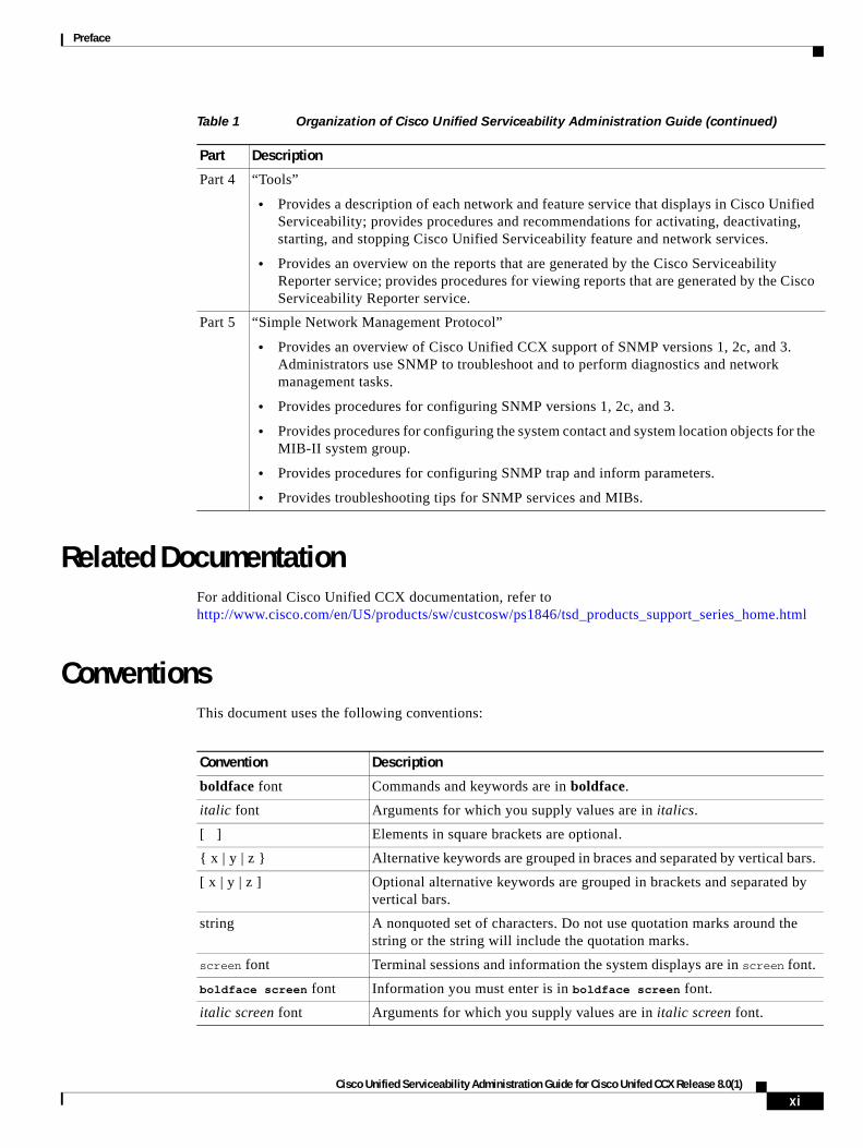
OrganizationThe following table shows the organization for this guide:
Table 1 Organization of Cisco Unified Serviceability Administration Guide
Part Description
Part 1 “Understanding Cisco Unified Serviceability”
Provides an overview of Cisco Unified Serviceability, including browser support and information on how to access and use the GUI.
Part 2 “Alarms”
• Provides an overview of Cisco Unified Serviceability alarms and alarm definitions.
• Provides procedures for configuring alarms in Cisco Unified Serviceability; provides procedures for searching and editing Cisco Unified Serviceability alarm definitions.
Part 3 “Trace”
• Provides an overview for configuring trace parameters in Cisco Unified Serviceability; also provides an overview of trace collection in the Cisco Unified CCX Real-Time Monitoring Tool.
• Provides procedures for configuring trace parameters for Cisco Unified Serviceability network and feature services; provides procedures for configuring the troubleshooting trace settings for services in Cisco Unified Serviceability.
xCisco Unified Serviceability Administration Guide for Cisco Unifed CCX Release 8.0(1)
Preface
Related DocumentationFor additional Cisco Unified CCX documentation, refer to http://www.cisco.com/en/US/products/sw/custcosw/ps1846/tsd_products_support_series_home.html
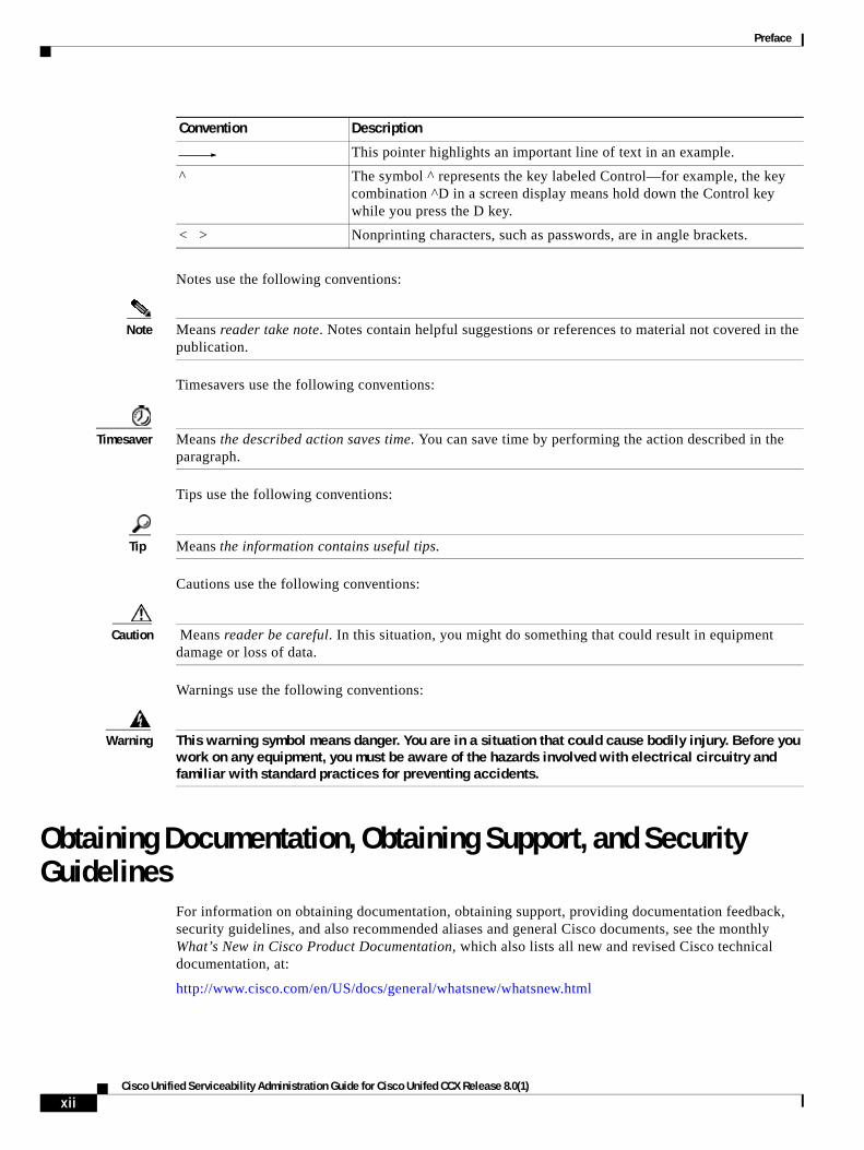
ConventionsThis document uses the following conventions:
Part 4 “Tools”
• Provides a description of each network and feature service that displays in Cisco Unified Serviceability; provides procedures and recommendations for activating, deactivating, starting, and stopping Cisco Unified Serviceability feature and network services.
• Provides an overview on the reports that are generated by the Cisco Serviceability Reporter service; provides procedures for viewing reports that are generated by the Cisco Serviceability Reporter service.
Part 5 “Simple Network Management Protocol”
• Provides an overview of Cisco Unified CCX support of SNMP versions 1, 2c, and 3. Administrators use SNMP to troubleshoot and to perform diagnostics and network management tasks.
• Provides procedures for configuring SNMP versions 1, 2c, and 3.
• Provides procedures for configuring the system contact and system location objects for the MIB-II system group.
• Provides procedures for configuring SNMP trap and inform parameters.
• Provides troubleshooting tips for SNMP services and MIBs.
Table 1 Organization of Cisco Unified Serviceability Administration Guide (continued)
Part Description
Convention Description
boldface font Commands and keywords are in boldface.
italic font Arguments for which you supply values are in italics.
[ ] Elements in square brackets are optional.
{ x | y | z } Alternative keywords are grouped in braces and separated by vertical bars.
[ x | y | z ] Optional alternative keywords are grouped in brackets and separated by vertical bars.
string A nonquoted set of characters. Do not use quotation marks around the string or the string will include the quotation marks.
screen font Terminal sessions and information the system displays are in screen font.
boldface screen font Information you must enter is in boldface screen font.
italic screen font Arguments for which you supply values are in italic screen font.
xiCisco Unified Serviceability Administration Guide for Cisco Unifed CCX Release 8.0(1)
Preface
Notes use the following conventions:
Note Means reader take note. Notes contain helpful suggestions or references to material not covered in the publication.
Timesavers use the following conventions:
Timesaver Means the described action saves time. You can save time by performing the action described in the paragraph.
Tips use the following conventions:
Tip Means the information contains useful tips.
Cautions use the following conventions:
Caution Means reader be careful. In this situation, you might do something that could result in equipment damage or loss of data.
Warnings use the following conventions:
Warning This warning symbol means danger. You are in a situation that could cause bodily injury. Before you work on any equipment, you must be aware of the hazards involved with electrical circuitry and familiar with standard practices for preventing accidents.
Obtaining Documentation, Obtaining Support, and Security Guidelines
For information on obtaining documentation, obtaining support, providing documentation feedback, security guidelines, and also recommended aliases and general Cisco documents, see the monthly What’s New in Cisco Product Documentation, which also lists all new and revised Cisco technical documentation, at:
http://www.cisco.com/en/US/docs/general/whatsnew/whatsnew.html
This pointer highlights an important line of text in an example.
^ The symbol ^ represents the key labeled Control—for example, the key combination ^D in a screen display means hold down the Control key while you press the D key.
< > Nonprinting characters, such as passwords, are in angle brackets.
Convention Description
xiiCisco Unified Serviceability Administration Guide for Cisco Unifed CCX Release 8.0(1)

Preface
GlossaryFor a complete list of terms used in Cisco Unified CCX and Cisco Unified IP IVR, see http://www.cisco.com/en/US/products/sw/custcosw/ps1846/prod_technical_reference_list.html.
xiiiCisco Unified Serviceability Administration Guide for Cisco Unifed CCX Release 8.0(1)

Preface
xivCisco Unified Serviceability Administration Guide for Cisco Unifed CCX Release 8.0(1)
P A R T 1
Cisco Unified Serviceability

Cisco Unified Serviceability Admin
C H A P T E R 1
Understanding Cisco Unified ServiceabilityNote This document uses the following abbreviation for the Cisco products - Unified CCX refers to Cisco Unified Contact Center Express and Cisco Unified IP IVR.
This chapter contains information on the following topics:
• Cisco Unified Serviceability Overview, page 1-1
• Reporting and Monitoring Tools, page 1-2
• Remote Serviceability Tools, page 1-2
• Customized Log-on Message, page 1-3
• Browser Support, page 1-3
• Where to Find More Information, page 1-3
Cisco Unified Serviceability OverviewCisco Unified Serviceability, a web-based troubleshooting tool, provides the following functionality:
• Saves alarms and events for troubleshooting and provides alarm message definitions for both Unified CCX and Unified Communications platform.
• Saves trace information to various log files for troubleshooting.
• Monitors real-time behavior of components through the Cisco Unified Real-Time Monitoring Tool (RTMT).
• Provides audit capability by logging any configuration changes by a user or as a result of the user action.
• Provides feature services that you can activate, deactivate, and view through the Service Activation window.
• Provides an interface for starting and stopping feature and network services.
• Generates and archives daily reports; for example, alert summary or server statistic reports.
• Allows Cisco Unified CCX to work as a managed device for SNMP remote management and troubleshooting for both Unified CCX and platform.
• Monitors the disk usage of the log partition on a server.
• Monitors the number of threads and processes in the system; uses cache to enhance the performance.
1-1istration Guide for Cisco Unifed CCX Release 8.0(1)
Chapter 1 Understanding Cisco Unified Serviceability Reporting and Monitoring Tools
Note Cisco Unified Serviceability in Unified CCX supports the functionality that is described in the Cisco Unified Serviceability Administration Guide; for tasks that are specific to Cisco Unified CCX Serviceability, refer to the Cisco Unified CCX Serviceability Administration Guide.
Tip Cisco RIS Data Collector provides Process and Thread statistic counters in the Cisco Unified Real-Time Monitoring Tool. To configure the maximum number of processes and threads that are allowed, so Cisco RIS Data Collector can provide these associated counters, access the Maximum Number of Threads and Process service parameter for the Cisco RIS Data Collector service in the administration interface for your configuration. For information on configuring service parameters, refer to the Cisco Unified CCX Serviceability Administration Guide.
Tip For Cisco Unified CCX, you must perform serviceability-related tasks in both Cisco Unified Serviceability and Cisco Unified CCX Serviceability; for example, you may need to start and stop services, configure alarms, and traces in both applications to troubleshoot a problem.
Reporting and Monitoring ToolsCisco Unified Serviceability provides the following reporting tools:
• Cisco Unified Real-Time Monitoring Tool (RTMT)—Monitors real-time behavior of components through RTMT; creates daily reports that you can access through the Serviceability Reports Archive. For more information, refer to the Cisco Unified CCX Real-Time Monitoring Tool Administration Guide.
• Serviceability Reports Archive—Archives reports that the Cisco Serviceability Reporter service generates.
Remote Serviceability ToolsTo supplement the management and administration of the Cisco Unified CCX server, you can use remote serviceability tools. Using these tools, you can gather system and debug information for diagnostic help or remote troubleshooting. The tools can process and report on a collection of local or remote Cisco Unified CCX configuration information. With customer permission, technical support engineers log on to a Cisco Unified CCX server and get a desktop or shell that allows them to perform any function that could be done from a local logon session.
Cisco Unified CCX supports the following capabilities for remote serviceability:
• Simple Network Management Protocol (SNMP)—Provides remote management for managed devices such as Cisco Unified CCX.
• Show Command Line Interface—Displays Cisco Unified CCX system data.
• CiscoWorks Lan Management Solution—Purchased separately from Cisco Unified CCX, supports maintenance of Cisco networks and devices. The following features, which serve as examples only, show how you can use CiscoWorks Lan Management Solution to manage Cisco Unified CCX operations:
1-2Cisco Unified Serviceability Administration Guide for Cisco Unifed CCX Release 8.0(1)
Chapter 1 Understanding Cisco Unified Serviceability Customized Log-on Message
Syslog Analysis tools monitor and manage a wide range of events and error messages concurrently on each Cisco Unified CCX server and other Cisco devices at your site.
Cisco Discovery Protocol (CDP) enables discovery of Cisco Unified CCX servers and management of those servers by CiscoWorks Lan Management Solution. After you use the CDP cache MIB of the direct neighboring device to discover Cisco Unified CCX, you can use CiscoWorks Lan Management Solution to query other Cisco Unified CCX-supported MIBs for provisions or statistics information about topology services, user tracking, path analysis, and other network management services. When you use CiscoWorks Lan Management Solution, you must keep the CDP driver enabled at all times to discover Cisco Unified CCX.
Customized Log-on MessageYou can upload a text file that contains a customized log-on message that appears on the initial Cisco Unified Serviceability window.
For more information and the procedure for uploading your customized log-on message, refer to the Cisco Unified Communications Operating System Administration Guide for Cisco Unified CCX and Cisco Unified IP IVR Release 8.0(1).
Browser SupportCisco supports these browsers with Cisco Unified Serviceability:
• Internet Explorer 6 or higher
• Firefox Version 2.0 or 3.0 browser
To access Cisco Unified Serviceability, you must browse to the application from a machine that runs the supported browser.
Note Cisco Unified Real-Time Monitoring Tool, a separate plug-in, supports a different set of browsers. Refer to the Cisco Unified CCX Real-Time Monitoring Tool Administration Guide for more information.
Cisco Unified Serviceability uses HTTPS to establish secure connections.
Tip Cisco Unified Serviceability does not support the buttons in your browser. Do not use the browser controls, for example, the Back button, when you perform configuration tasks.
Where to Find More InformationAdditional Cisco Documentation
• Cisco Unified CCX Real-Time Monitoring Tool Administration Guide
• Cisco Unified CCX Serviceability Administration Guide
• Cisco Unified CCX Administration Guide
1-3Cisco Unified Serviceability Administration Guide for Cisco Unifed CCX Release 8.0(1)

Chapter 1 Understanding Cisco Unified Serviceability Where to Find More Information
1-4Cisco Unified Serviceability Administration Guide for Cisco Unifed CCX Release 8.0(1)
Cisco Unified Serviceability Admin
C H A P T E R 2
Using Cisco Unified ServiceabilityThis chapter comprises the following topics:
• Accessing Cisco Unified Serviceability, page 2-1
• Installing the Server Certificate, page 2-2
• Using the Cisco Unified Serviceability Interface, page 2-5
• Using Accessibility Features, page 2-6
• Where to Find More Information, page 2-7
Accessing Cisco Unified ServiceabilityYou can access the Serviceability application
• by entering https://<server name or IP address>:8443/ccmservice/ in a browser window.
• by choosing Cisco Unified Serviceability in the Navigation menu in the Cisco Unified CCX Administration console.
• by choosing Application > Serviceability Webpage in the Real-Time Monitoring Tool (RTMT) menu and then entering a valid username and password.
Note You can access Cisco Unified Serviceability using the Application administration user credentials as configured during installation of Unified CCX. Cisco Unified OS Administration and Disaster Recovery System require a separate authentication procedure.
The system uses the Cisco Tomcat service to authenticate users before allowing access to the web application. If you get a security alert that the site is not trusted, this indicates that the server certificate has not yet downloaded.
To access Cisco Unified Serviceability, perform the following procedure:
Procedure
Step 1 In a supported browser, browse to the server where the Cisco Unified Serviceability service runs.
2-1istration Guide for Cisco Unifed CCX Release 8.0(1)
Chapter 2 Using Cisco Unified Serviceability Installing the Server Certificate
Tip In the supported browser, enter https://<server name or IP address>:8443/ccmservice/, where server name or IP address equals the server where the Cisco Unified Serviceability service runs and 8443 equals the port number for HTTPS.
Step 2 If the system prompts you about certificates, see the “Installing the Server Certificate” section on page 2-2.
Step 3 Enter a valid username and password; click Login.
To clear the username and password, click Reset.
Additional Information
See the “Related Topics” section on page 2-7.
Installing the Server CertificateThis section contains information on the following topics:
• HTTPS Overview for Internet Explorer, page 2-2
• Installing the Certificate with Internet Explorer 6, page 2-3
• Installing the Certificate with Internet Explorer 7, page 2-4
Hypertext Transfer Protocol over Secure Sockets Layer (SSL), which secures communication between the browser client and the Tomcat web server, uses a certificate and a public key to encrypt the data that is transferred over the internet. HTTPS, which ensures the identity of the server, supports applications, such as Cisco Unified Serviceability. HTTPS also ensures that the user login password transports securely via the web.
Note Due to the way IE 7 handles certificates, this browser displays an error status after you import the server certificate. This status persists if you reenter the URL or refresh or relaunch the browser and does not indicate an error. Refer to the “Installing the Certificate with Internet Explorer 7” section on page 2-4 for more information.
HTTPS Overview for Internet ExplorerOn the first attempt to access Cisco Unified Serviceability, a Security Alert dialog box, which indicates that the server is not trusted because the server certificate does not exist in the trusted folder, displays. When the dialog box displays, perform one of the following tasks:
• By clicking Yes, you choose to trust the certificate for the current web session only. If you trust the certificate for the current session only, the Security Alert dialog box displays each time that you access the application: that is, until you install the certificate in the trusted folder.
• By clicking View Certificate > Install Certificate, you indicate that you intend to perform certificate installation tasks, so you always trust the certificate. If you install the certificate in the trusted folder, the Security Alert dialog box does not display each time that you access the web application.
2-2Cisco Unified Serviceability Administration Guide for Cisco Unifed CCX Release 8.0(1)
Chapter 2 Using Cisco Unified Serviceability Installing the Server Certificate
• By clicking No, you cancel the action. No authentication occurs, and you cannot access the web application.
Note The system issues the certificate by using the hostname. If you attempt to access a web application by using the IP address, the Security Alert dialog box displays, even though you installed the certificate.
Additional Information
See the “Related Topics” section on page 2-7.
Installing the Certificate with Internet Explorer 6Perform the following procedure to save the HTTPS certificate in the trusted folder.
Procedure
Step 1 Browse to the application on the Tomcat web server.
Step 2 When the Security Alert dialog box displays, click View Certificate. To verify certificate details, click the Details tab.
Step 3 In the Certificate pane, click Install Certificate.
Step 4 When the Certificate Import Wizard displays, click Next.
Step 5 Click the Place all certificates in the following store radio button; click Browse.
Step 6 Browse to Trusted Root Certification Authorities; select it and click OK.
Step 7 Click Next.
Step 8 Click Finish.
A Security Warning Box displays the certificate thumbprint for you.
Step 9 To install the certificate, click Yes.
A message states that the import was successful. Click OK.
Step 10 In the lower, right corner of the dialog box, click OK.
Step 11 To trust the certificate, so you do not receive the dialog box again, click Yes.
Tip You can verify the certificate was installed successfully by clicking the Certification Path tab in the Certificate pane.
Additional Information
See the “Related Topics” section on page 2-7.
2-3Cisco Unified Serviceability Administration Guide for Cisco Unifed CCX Release 8.0(1)
Chapter 2 Using Cisco Unified Serviceability Installing the Server Certificate
Installing the Certificate with Internet Explorer 7Internet Explorer 7 adds security features that change the way that the browser handles Cisco certificates for website access. Because Cisco provides a self-signed certificate for the Cisco Unified CCX server, Internet Explorer 7 flags the Cisco Unified CCX website as untrusted and provides a certificate error, even when the trust store contains the server certificate.
Note Internet Explorer 7, which is a Windows Vista feature, also runs on Windows XP Service Pack 2 (SP2), Windows XP Professional x64 Edition, and Windows Server 2003 Service Pack 1 (SP1). Java Runtime Environment (JRE) must be present to provide Java-related browser support for IE.
Be sure to import the Cisco Unified CCX certificate to Internet Explorer 7 to secure access without having to reload the certificate every time that you restart the browser. If you continue to a website that has a certificate warning and the certificate is not in the trust store, Internet Explorer 7 remembers the certificate for the current session only.
After you download the server certificate, Internet Explorer 7 continues to display certificate errors for the website. You can ignore the security warnings when the Trusted Root Certificate Authority trust store for the browser contains the imported certificate.
The following procedure describes how to import the Cisco Unified CCX certificate to the root certificate trust store for Internet Explorer 7.
Procedure
Step 1 Browse to application on the Tomcat server by entering the hostname (server name) or IP address in the browser.
The browser displays a Certificate Error: Navigation Blocked message to indicate that this website is untrusted.
Step 2 To access the server, click Continue to this website (not recommended)
The administration window displays, and the browser displays the address bar and Certificate Error status in red.
Step 3 To import the server certificate, click the Certificate Error status box to display the status report. Click the View Certificates link in the report.
Step 4 Verify the certificate details.
The Certification Path tab displays “This CA Root certificate is not trusted because it is not in the Trusted Root Certification Authorities store.”
Step 5 Select the General tab in the Certificate window and click Install Certificate.
The Certificate Import Wizard launches.
Step 6 To start the Wizard, click Next.
The Certificate Store window displays.
Step 7 Verify that the Automatic option, which allows the wizard to select the certificate store for this certificate type, is selected and click Next.
Step 8 Verify the setting and click Finish.
A security warning displays for the import operation.
Step 9 To install the certificate, click Yes.
2-4Cisco Unified Serviceability Administration Guide for Cisco Unifed CCX Release 8.0(1)
Chapter 2 Using Cisco Unified Serviceability Using the Cisco Unified Serviceability Interface
The Import Wizard displays “The import was successful.”
Step 10 Click OK. The next time that you click the View certificates link, the Certification Path tab in the Certificate window displays “This certificate is OK.”
Step 11 To verify that the trust store contains the imported certificate, click Tools > Internet Options in the Internet Explorer toolbar and select the Content tab. Click Certificates and select the Trusted Root Certifications Authorities tab. Scroll to find the imported certificate in the list.
After importing the certificate, the browser continues to display the address bar and a Certificate Error status in red. The status persists even if you reenter the hostname or IP address or refresh or relaunch the browser.
Additional Information
See the “Related Topics” section on page 2-7.
Using the Cisco Unified Serviceability InterfaceIn addition to performing troubleshooting and service-related tasks in Cisco Unified Serviceability, you can perform the following tasks:
• To display documentation for a single window, choose Help > This Page in Cisco Unified Serviceability.
• To display a list of documents that are available with this release (or to access the online help index), choose Help > Contents in Cisco Unified Serviceability.
• To verify the version of Cisco Unified Serviceability that runs on the server, choose Help > About or click the About link in the upper, right corner of the window.
• To go directly to the home page in Cisco Unified Serviceability from a configuration window, choose Cisco Unified Serviceability from the Navigation drop-down list box in the upper, right corner of the window.
Note In some scenarios, you cannot access the Cisco Unified Serviceability from Cisco Unified OS Administration. A “Loading, please wait” message displays indefinitely. If the redirect fails, log out from Cisco Unified OS Administration, select Cisco Unified Serviceability from the navigation menu, and log in to Cisco Unified Serviceability.
• To access other application GUIs, choose the appropriate application from the Navigation drop-down list box in the upper, right corner of the window; then, click Go.
• To log out of Cisco Unified Serviceability, click the Logout link in the upper, right corner of the Cisco Unified Serviceability window.
• In each Cisco Unified Serviceability configuration window, configuration icons display that correspond to the configuration buttons at the bottom of the window; for example, you can either click the Save icon or the Save button to complete the task.
Tip Cisco Unified Serviceability does not support the buttons in your browser. Do not use the browser buttons, for example, the Back button, when you perform configuration tasks.
2-5Cisco Unified Serviceability Administration Guide for Cisco Unifed CCX Release 8.0(1)
Chapter 2 Using Cisco Unified Serviceability Using Accessibility Features
Tip When a session has been idle for more than 30 minutes, the Cisco Unified Serviceability user interface allows you to make changes before indicating that the session has timed out and redirecting you to the login window. After you log in again, you may have to repeat those changes. This behavior occurs in the Alarm, Trace, Service Activation, Control Center, and SNMP windows. If you know that the session has been idle for more than 30 minutes, log out by using the Logout button before making any changes in the user interface.
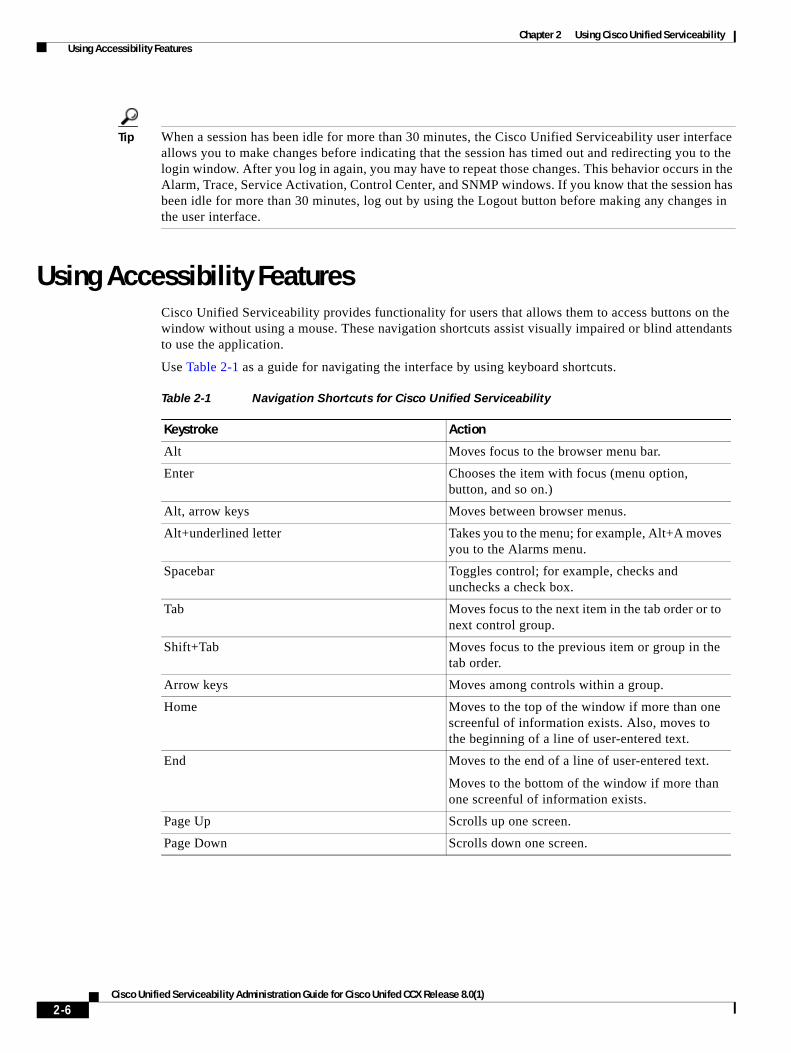
Using Accessibility FeaturesCisco Unified Serviceability provides functionality for users that allows them to access buttons on the window without using a mouse. These navigation shortcuts assist visually impaired or blind attendants to use the application.
Use Table 2-1 as a guide for navigating the interface by using keyboard shortcuts.
Table 2-1 Navigation Shortcuts for Cisco Unified Serviceability
Keystroke Action
Alt Moves focus to the browser menu bar.
Enter Chooses the item with focus (menu option, button, and so on.)
Alt, arrow keys Moves between browser menus.
Alt+underlined letter Takes you to the menu; for example, Alt+A moves you to the Alarms menu.
Spacebar Toggles control; for example, checks and unchecks a check box.
Tab Moves focus to the next item in the tab order or to next control group.
Shift+Tab Moves focus to the previous item or group in the tab order.
Arrow keys Moves among controls within a group.
Home Moves to the top of the window if more than one screenful of information exists. Also, moves to the beginning of a line of user-entered text.
End Moves to the end of a line of user-entered text.
Moves to the bottom of the window if more than one screenful of information exists.
Page Up Scrolls up one screen.
Page Down Scrolls down one screen.
2-6Cisco Unified Serviceability Administration Guide for Cisco Unifed CCX Release 8.0(1)
Chapter 2 Using Cisco Unified Serviceability Where to Find More Information
Where to Find More InformationRelated Topics
• Accessing Cisco Unified Serviceability, page 2-1
• Installing the Server Certificate, page 2-2
• Using the Cisco Unified Serviceability Interface, page 2-5
• Using Accessibility Features, page 2-6
Additional Cisco Documentation
• Cisco Unified CCX Administration Guide
• Cisco Unified CCX Serviceability Administration Guide
• Cisco Unified CCX Real-Time Monitoring Tool Administration Guide
2-7Cisco Unified Serviceability Administration Guide for Cisco Unifed CCX Release 8.0(1)

Chapter 2 Using Cisco Unified Serviceability Where to Find More Information
2-8Cisco Unified Serviceability Administration Guide for Cisco Unifed CCX Release 8.0(1)

P A R T 2
Alarms

Cisco Unified Serviceability Admin
C H A P T E R 3
Understanding AlarmsThis chapter, which provides information on Cisco Unified Serviceability alarms, contains the following topics:
• Understanding Alarms, page 3-1
• Alarm Configuration, page 3-2
• Alarm Definitions, page 3-2
• Viewing Alarm Information, page 3-3
• Alarm Configuration Checklist, page 3-3
• Where to Find More Information, page 3-4
Understanding AlarmsCisco Unified Serviceability alarms provide information on runtime status and the state of the system, so you can troubleshoot problems that are associated with your system; for example, to identify issues with the Disaster Recovery System. Alarm information, which includes an explanation and recommended action, also includes the application name, machine name, and so on, to help you perform troubleshooting. If you have clusters, this is even true for problems that are not on your local Cisco Unified CCX.
You configure the alarm interface to send alarm information to multiple locations, and each location can have its own alarm event level (from debug to emergency). You can direct alarms to the Syslog Viewer (local syslog), Syslog file (remote syslog), an SDI trace log file, or to all destinations.
When a service issues an alarm, the alarm interface sends the alarm information to the locations that you configure (and that are specified in the routing list in the alarm definition) (for example, SDI trace). The system can either forward the alarm information, as is the case with SNMP traps, or the system can write the alarm information to its final destination (such as a log file).
Note Cisco Unified CCX supports SNMP traps.
Tip For the Remote Syslog Server, do not specify a Cisco Unified CCX server, which cannot accept syslog messages from other servers.
3-1istration Guide for Cisco Unifed CCX Release 8.0(1)
Chapter 3 Understanding Alarms Alarm Configuration
You use the Trace and Log Central option in the Cisco Unified CCX Real-Time Monitoring Tool (RTMT) to collect alarms that get sent to an SDI trace log file. You use the SysLog Viewer in RTMT to view alarm information that gets sent to the local syslog.
Alarm ConfigurationYou can configure alarms for services, such as Cisco Database Layer Monitor, in Cisco Unified Serviceability. Then, you configure the location(s), such as Syslog Viewer (local syslog), where you want the system to send the alarm information. With this option, you can
• Configure alarms for services on a particular server or on both servers in a Unified CCX cluster.
• Configure different remote syslog servers for the configured service(s) or server(s)
• Configure different alarm event level settings for different destinations
The alarms include system (OS/hardware platform), application (services), and security alarms.
Cisco Unified CCX also uses alarms, which are available in Cisco Unified CCX Serviceability. For detailed information on how to configure alarms in Cisco Unified CCX, see the Cisco Unified CCX Serviceability Administration Guide.
Note If local syslog is enabled for an application alarm, the system sends the alarm to the local syslog server when the alarm exceeds the local syslog threshold . If remote syslog is also enabled in Cisco Unified Serviceability, the system forwards the alarm to the remote syslog server by using the application threshold that is configured in Cisco Unified Serviceability.
The event level/severity settings provide a filtering mechanism for the alarms and messages that the system collects. This setting helps to prevent the Syslog and trace files from becoming overloaded. The system forwards only alarms and messages that exceed the configured threshold.
For more information about the severity levels attached to alarms and events, see the “Alarm Definitions” section on page 3-2.
Alarm DefinitionsUsed for reference, alarm definitions describe alarm messages: what they mean and how to recover from them. You search the Alarm Definitions window for alarm information of Unified CCX Administration and platform. When you click any service-specific alarm definition, a description of the alarm information (including any user-defined text that you have added) and a recommended action display.
You can search for definitions of all alarms that display in Cisco Unified Serviceability. To aid you with troubleshooting problems, the definitions, which exist in a corresponding catalog, include the alarm name, description, explanation, recommended action, severity, parameters, monitors, and so on.
When the system generates an alarm, it uses the alarm definition name in the alarm information, so you can identify the alarm. In the alarm definition, you can view the routing list, which specifies the locations where the system can send the alarm information. The routing list may include the following locations, which correlate to the locations that you can configure in the Alarm Configuration window:
• SDI —The system sends the alarm information to the SDI trace if you enable the alarm for this option and specify an appropriate event level in the Alarm Configuration window.
3-2Cisco Unified Serviceability Administration Guide for Cisco Unifed CCX Release 8.0(1)
Chapter 3 Understanding Alarms Viewing Alarm Information
• Sys Log—The system sends the alarm information to the remote syslog server if you enable the alarm for this option, specify an appropriate event level in the Alarm Configuration window, and enter a server name or IP address for the remote syslog server.
• Event Log—The system sends the alarm information to the local syslog, which you can view in the SysLog Viewer in the Cisco Unified CCX Real-Time Monitoring Tool (RTMT), if you enable the alarm for this option and specify an appropriate event level in the Alarm Configuration window.
• Data Collector—System sends the alarm information to the real-time information system (RIS data collector) (for alert purposes only). You cannot configure this option in the Alarm Configuration window.
Tip If the SNMP Traps location displays in the routing list, the system forwards the alarm information to the appropriate SNMP agents, which generates the required traps according to the definition in the respective MIB.
The system sends an alarm if the configured alarm event level for the specific location in the Alarm Configuration window is equal to or lower than the severity that is listed in the alarm definition. For example, if the severity in the alarm definition equals WARNING_ALARM, and, in the Alarm Configuration window, you configure the alarm event level for the specific destination as Warning, Notice, Informational, or Debug, which are lower event levels, the system sends the alarm to the corresponding destination. If you configure the alarm event level as Emergency, Alert, Critical, or Error, the system does not send the alarm to the corresponding location.
For each Cisco Unified Serviceability alarm definition, you can include an additional explanation or recommendation. All administrators have access to the added information. You directly enter information into the User Defined Text pane that displays in the Alarm Details window. Standard horizontal and vertical scroll bars support scrolling. Cisco Unified Serviceability adds the information to the database.
Viewing Alarm InformationYou view alarm information to determine whether problems exist. The method that you use to view the alarm information depends on the destination that you chose when you configured the alarm. You can view alarm information that is sent to the SDI trace log file by using the Trace and Log Central option in RTMT or by using a text editor. You can view alarm information that gets sent to local syslog by using the SysLog Viewer in RTMT.
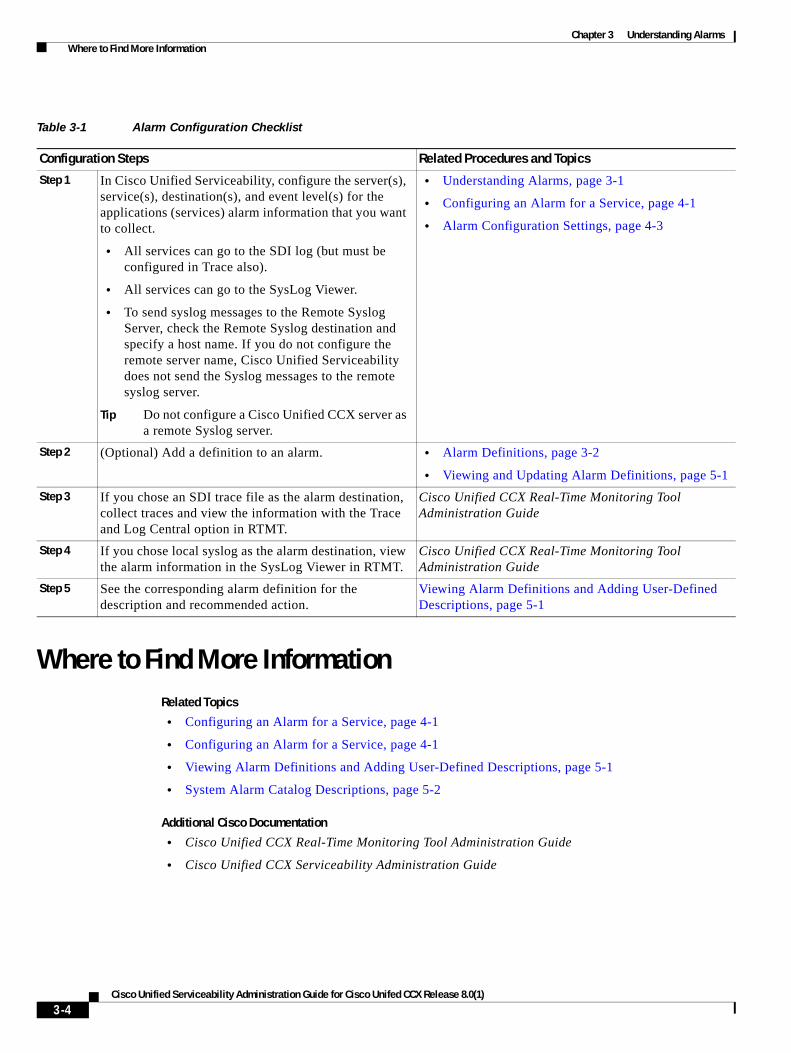
Alarm Configuration ChecklistTable 3-1 provides an overview of the steps for configuring alarms.
3-3Cisco Unified Serviceability Administration Guide for Cisco Unifed CCX Release 8.0(1)
Chapter 3 Understanding Alarms Where to Find More Information
Where to Find More InformationRelated Topics
• Configuring an Alarm for a Service, page 4-1
• Configuring an Alarm for a Service, page 4-1
• Viewing Alarm Definitions and Adding User-Defined Descriptions, page 5-1
• System Alarm Catalog Descriptions, page 5-2
Additional Cisco Documentation
• Cisco Unified CCX Real-Time Monitoring Tool Administration Guide
• Cisco Unified CCX Serviceability Administration Guide
Table 3-1 Alarm Configuration Checklist
Configuration Steps Related Procedures and Topics
Step 1 In Cisco Unified Serviceability, configure the server(s), service(s), destination(s), and event level(s) for the applications (services) alarm information that you want to collect.
• All services can go to the SDI log (but must be configured in Trace also).
• All services can go to the SysLog Viewer.
• To send syslog messages to the Remote Syslog Server, check the Remote Syslog destination and specify a host name. If you do not configure the remote server name, Cisco Unified Serviceability does not send the Syslog messages to the remote syslog server.
Tip Do not configure a Cisco Unified CCX server as a remote Syslog server.
• Understanding Alarms, page 3-1
• Configuring an Alarm for a Service, page 4-1
• Alarm Configuration Settings, page 4-3
Step 2 (Optional) Add a definition to an alarm. • Alarm Definitions, page 3-2
• Viewing and Updating Alarm Definitions, page 5-1
Step 3 If you chose an SDI trace file as the alarm destination, collect traces and view the information with the Trace and Log Central option in RTMT.
Cisco Unified CCX Real-Time Monitoring Tool Administration Guide
Step 4 If you chose local syslog as the alarm destination, view the alarm information in the SysLog Viewer in RTMT.
Cisco Unified CCX Real-Time Monitoring Tool Administration Guide
Step 5 See the corresponding alarm definition for the description and recommended action.
Viewing Alarm Definitions and Adding User-Defined Descriptions, page 5-1
3-4Cisco Unified Serviceability Administration Guide for Cisco Unifed CCX Release 8.0(1)
Cisco Unified Serviceability Admin
C H A P T E R 4
Configuring AlarmsThis chapter contains the following topics:
• Configuring an Alarm for a Service, page 4-1
• Service Groups in Alarm Configuration, page 4-3
• Alarm Configuration Settings, page 4-3
• Where to Find More Information, page 4-5
Configuring an Alarm for a ServiceThis section describes how to add or update an alarm for a feature or network service that you manage through Cisco Unified Serviceability.
Note Cisco recommends that you do not change SNMP Trap and Catalog configurations.
Refer to your online OS documentation for more information on how to use your standard registry editor.
Procedure
Step 1 Choose Alarm > Configuration.
The Alarm Configuration window displays.
Step 2 From the Server drop-down list box, choose the server for which you want to configure the alarm; then, click Go.
Step 3 From the Service Group drop-down list box, choose the category of service, for example, Database and Admin Services, for which you want to configure the alarm; then, click Go.
Tip For a list of services that correspond to the service groups, see Table 4-1.
Step 4 From the Service drop-down list box, choose the service for which you want to configure the alarm; then, click Go.
Only services that support the service group and your configuration display.
4-1istration Guide for Cisco Unifed CCX Release 8.0(1)
Chapter 4 Configuring Alarms Configuring an Alarm for a Service
Tip The drop-down list box displays active and inactive services.
In the Alarm Configuration window, a list of alarm monitors with the event levels displays for the chosen service.In addition, the Apply to All Nodes check box displays. In a High Availability (HA) deployment, you can apply the alarm configuration for the service to all servers in the cluster by checking the Apply to All Nodes check box.
Step 5 Configure the settings, as described in Table 4-2, which includes descriptions for monitors and event levels.
Step 6 To save your configuration, click the Save button.
Note To set the default, click the Set Default button; then, click Save.
Services That Use Cisco Tomcat
Some services in Unified Serviceability use Cisco Tomcat for alarm generation. For example, the system login alarm AuthenticationFailed uses Cisco Tomcat. To generate alarms for such services, perform the following procedure:
Procedure
Step 1 In Cisco Unified Serviceability, choose Alarm > Configuration.
Step 2 From the Server drop-down list box, choose the server for which you want to configure the alarm; then, click Go.
Step 3 From the Services Group drop-down list box, choose Platform Services; then, click Go.
Step 4 From the Services drop-down list box, choose Cisco Tomcat; then, click Go.
Step 5 Configure the settings, as described in Table 4-2, which includes descriptions for monitors and event levels.
Step 6 To save your configuration, click the Save button.
Tip The system sends the alarm if the configured alarm event level for the specific destination in the Alarm Configuration window is equal to or lower than the severity that is listed in the alarm definition. For example, if the severity in the alarm definition equals WARNING_ALARM, and, in the Alarm Configuration window, you configure the alarm event level for the specific destination as Warning, Notice, Informational, or Debug, which are lower event levels, the system sends the alarm to the corresponding destination. If you configure the alarm event level as Emergency, Alert, Critical, or Error, which are higher severity levels, the system does not send the alarm to the corresponding location.
Additional Information
See the “Related Topics” section on page 4-5.
4-2Cisco Unified Serviceability Administration Guide for Cisco Unifed CCX Release 8.0(1)
Chapter 4 Configuring Alarms Service Groups in Alarm Configuration
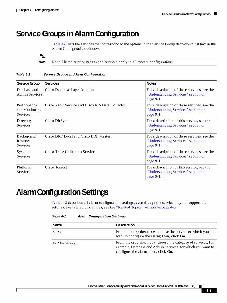
Service Groups in Alarm ConfigurationTable 4-1 lists the services that correspond to the options in the Service Group drop-down list box in the Alarm Configuration window.
Note Not all listed service groups and services apply to all system configurations.
Alarm Configuration SettingsTable 4-2 describes all alarm configuration settings, even though the service may not support the settings. For related procedures, see the “Related Topics” section on page 4-5.
Table 4-1 Service Groups in Alarm Configuration
Service Group Services Notes
Database and Admin Services
Cisco Database Layer Monitor For a description of these services, see the “Understanding Services” section on page 9-1.
Performance and Monitoring Services
Cisco AMC Service and Cisco RIS Data Collector For a description of these services, see the “Understanding Services” section on page 9-1.
Directory Services
Cisco DirSync For a description of this service, see the “Understanding Services” section on page 9-1.
Backup and Restore Services
Cisco DRF Local and Cisco DRF Master For a description of these services, see the “Understanding Services” section on page 9-1.
System Services
Cisco Trace Collection Service For a description of these services, see the “Understanding Services” section on page 9-1.
Platform Services
Cisco Tomcat For a description of this service, see the “Understanding Services” section on page 9-1.
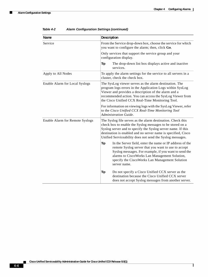
Table 4-2 Alarm Configuration Settings
Name Description
Server From the drop-down box, choose the server for which you want to configure the alarm; then, click Go.
Service Group From the drop-down box, choose the category of services, for example, Database and Admin Services, for which you want to configure the alarm; then, click Go.
4-3Cisco Unified Serviceability Administration Guide for Cisco Unifed CCX Release 8.0(1)
Chapter 4 Configuring Alarms Alarm Configuration Settings
Service From the Service drop-down box, choose the service for which you want to configure the alarm; then, click Go.
Only services that support the service group and your configuration display.
Tip The drop-down list box displays active and inactive services.
Apply to All Nodes To apply the alarm settings for the service to all servers in a cluster, check the check box.
Enable Alarm for Local Syslogs The SysLog viewer serves as the alarm destination. The program logs errors in the Application Logs within SysLog Viewer and provides a description of the alarm and a recommended action. You can access the SysLog Viewer from the Cisco Unified CCX Real-Time Monitoring Tool.
For information on viewing logs with the SysLog Viewer, refer to the Cisco Unified CCX Real-Time Monitoring Tool Administration Guide.
Enable Alarm for Remote Syslogs The Syslog file serves as the alarm destination. Check this check box to enable the Syslog messages to be stored on a Syslog server and to specify the Syslog server name. If this destination is enabled and no server name is specified, Cisco Unified Serviceability does not send the Syslog messages.
Tip In the Server field, enter the name or IP address of the remote Syslog server that you want to use to accept Syslog messages. For example, if you want to send the alarms to CiscoWorks Lan Management Solution, specify the CiscoWorks Lan Management Solution server name.
Tip Do not specify a Cisco Unified CCX server as the destination because the Cisco Unified CCX server does not accept Syslog messages from another server.
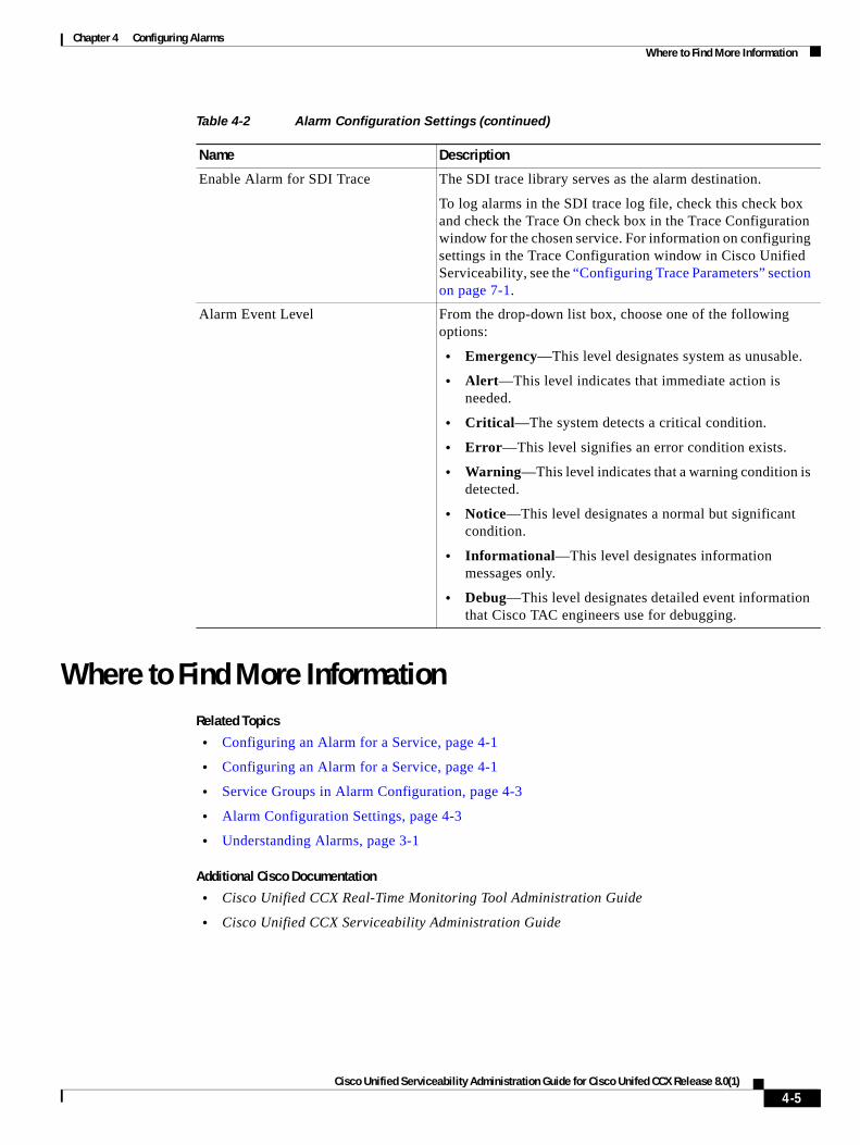
Table 4-2 Alarm Configuration Settings (continued)
Name Description
4-4Cisco Unified Serviceability Administration Guide for Cisco Unifed CCX Release 8.0(1)
Chapter 4 Configuring Alarms Where to Find More Information
Where to Find More InformationRelated Topics
• Configuring an Alarm for a Service, page 4-1
• Configuring an Alarm for a Service, page 4-1
• Service Groups in Alarm Configuration, page 4-3
• Alarm Configuration Settings, page 4-3
• Understanding Alarms, page 3-1
Additional Cisco Documentation
• Cisco Unified CCX Real-Time Monitoring Tool Administration Guide
• Cisco Unified CCX Serviceability Administration Guide
Enable Alarm for SDI Trace The SDI trace library serves as the alarm destination.
To log alarms in the SDI trace log file, check this check box and check the Trace On check box in the Trace Configuration window for the chosen service. For information on configuring settings in the Trace Configuration window in Cisco Unified Serviceability, see the “Configuring Trace Parameters” section on page 7-1.
Alarm Event Level From the drop-down list box, choose one of the following options:
• Emergency—This level designates system as unusable.
• Alert—This level indicates that immediate action is needed.
• Critical—The system detects a critical condition.
• Error—This level signifies an error condition exists.
• Warning—This level indicates that a warning condition is detected.
• Notice—This level designates a normal but significant condition.
• Informational—This level designates information messages only.
• Debug—This level designates detailed event information that Cisco TAC engineers use for debugging.
Table 4-2 Alarm Configuration Settings (continued)
Name Description
4-5Cisco Unified Serviceability Administration Guide for Cisco Unifed CCX Release 8.0(1)

Chapter 4 Configuring Alarms Where to Find More Information
4-6Cisco Unified Serviceability Administration Guide for Cisco Unifed CCX Release 8.0(1)
Cisco Unified Serviceability Admin
C H A P T E R 5
Viewing and Updating Alarm DefinitionsThis chapter, which provides procedural information to search, view, and create user information for alarm definitions that display in Cisco Unified Serviceability, contains the following topics:
• Viewing Alarm Definitions and Adding User-Defined Descriptions, page 5-1
• System Alarm Catalog Descriptions, page 5-2
• Where to Find More Information, page 5-3
Viewing Alarm Definitions and Adding User-Defined Descriptions
This section describes how to search and view an alarm definition for Unified CCX and platform components through Cisco Unified Serviceability.
Procedure
Step 1 In Cisco Unified Serviceability, choose Alarm > Definitions.
The Alarm Message Definitions window displays.
Step 2 From the Find alarms where drop-down list box, choose the catalog for which you want to view the definitions.
Step 3 From the Equals drop-down list box, choose a catalog of alarm definitions or enter the alarm name in the Enter Alarm Name field. For a list of System Alarm Catalog options, see Table 5-1.
Step 4 Click the Find button.
The definitions list displays for the alarm catalog that you chose.
Tip Multiple pages of alarm definitions may exist. To choose another page, click the appropriate navigation button at the bottom of the Alarm Message Definitions window or enter a page number in the Page field. To change the number of alarms that display in the window, choose a different value from the Rows per Page drop-down list box.
Step 5 In the list, click the hyperlink alarm definition for which you want to view alarm details, such as a description, alarm severity, and so on.
The Alarm Information window displays.
5-1istration Guide for Cisco Unifed CCX Release 8.0(1)
Chapter 5 Viewing and Updating Alarm Definitions System Alarm Catalog Descriptions
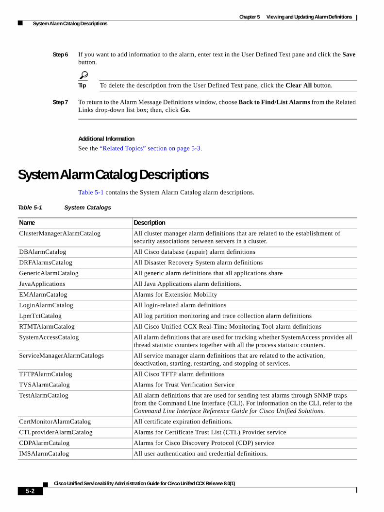
Step 6 If you want to add information to the alarm, enter text in the User Defined Text pane and click the Save button.
Tip To delete the description from the User Defined Text pane, click the Clear All button.
Step 7 To return to the Alarm Message Definitions window, choose Back to Find/List Alarms from the Related Links drop-down list box; then, click Go.
Additional Information
See the “Related Topics” section on page 5-3.
System Alarm Catalog DescriptionsTable 5-1 contains the System Alarm Catalog alarm descriptions.
Table 5-1 System Catalogs
Name Description
ClusterManagerAlarmCatalog All cluster manager alarm definitions that are related to the establishment of security associations between servers in a cluster.
DBAlarmCatalog All Cisco database (aupair) alarm definitions
DRFAlarmsCatalog All Disaster Recovery System alarm definitions
GenericAlarmCatalog All generic alarm definitions that all applications share
JavaApplications All Java Applications alarm definitions.
EMAlarmCatalog Alarms for Extension Mobility
LoginAlarmCatalog All login-related alarm definitions
LpmTctCatalog All log partition monitoring and trace collection alarm definitions
RTMTAlarmCatalog All Cisco Unified CCX Real-Time Monitoring Tool alarm definitions
SystemAccessCatalog All alarm definitions that are used for tracking whether SystemAccess provides all thread statistic counters together with all the process statistic counters.
ServiceManagerAlarmCatalogs All service manager alarm definitions that are related to the activation, deactivation, starting, restarting, and stopping of services.
TFTPAlarmCatalog All Cisco TFTP alarm definitions
TVSAlarmCatalog Alarms for Trust Verification Service
TestAlarmCatalog All alarm definitions that are used for sending test alarms through SNMP traps from the Command Line Interface (CLI). For information on the CLI, refer to the Command Line Interface Reference Guide for Cisco Unified Solutions.
CertMonitorAlarmCatalog All certificate expiration definitions.
CTLproviderAlarmCatalog Alarms for Certificate Trust List (CTL) Provider service
CDPAlarmCatalog Alarms for Cisco Discovery Protocol (CDP) service
IMSAlarmCatalog All user authentication and credential definitions.
5-2Cisco Unified Serviceability Administration Guide for Cisco Unifed CCX Release 8.0(1)
Chapter 5 Viewing and Updating Alarm Definitions Where to Find More Information
Additional Information
See the “Related Topics” section on page 5-3.
Where to Find More InformationRelated Topics
• Understanding Alarms, page 3-1
• Viewing Alarm Definitions and Adding User-Defined Descriptions, page 5-1
• System Alarm Catalog Descriptions, page 5-2
5-3Cisco Unified Serviceability Administration Guide for Cisco Unifed CCX Release 8.0(1)

Chapter 5 Viewing and Updating Alarm Definitions Where to Find More Information
5-4Cisco Unified Serviceability Administration Guide for Cisco Unifed CCX Release 8.0(1)

P A R T 3
Trace

Cisco Unified Serviceability Admin
C H A P T E R 6
Understanding TraceThis chapter, which provides information on Cisco Unified Serviceability trace, contains the following topics:
• Understanding Trace, page 6-1
• Trace Configuration, page 6-1
• Troubleshooting Trace Settings, page 6-2
• Trace Collection, page 6-2
• Trace Configuration and Collection Checklist, page 6-3
• Where to Find More Information, page 6-4
Understanding TraceCisco Unified Serviceability provides trace tools to assist you in troubleshooting issues with your voice application. Cisco Unified Serviceability supports SDI (System Diagnostic Interface) trace and Log4J trace (for Java applications).
You use the Trace Configuration window to specify the level of information that you want traced as well the type of information that you want to be included in each trace file.
In the Alarm Configuration window, you can direct alarms to various locations including SDI trace log files. After you have configured information that you want to include in the trace files for the various services, you can collect and view trace files by using the trace and log central option in the Cisco Unified Real-Time Monitoring Tool.
Trace ConfigurationYou can configure trace parameters for any feature or network service that displays in Cisco Unified Serviceability. If you have a Cisco Unified CCX cluster, (Cisco Unified CCX only) you can configure trace parameters for any feature or network service that is available on any Cisco Unified CCX server in the cluster. Use the Trace Configuration window to specify the parameters that you want to trace for troubleshooting problems.
You can configure the level of information that you want traced (debug level), what information you want to trace (trace fields), and information about the trace files (such as number of files per service, size of file, and time that the data is stored in the trace files.) If you have a Cisco Unified CCX cluster, you can configure trace for a single service or apply the trace settings for that service to all servers in the cluster.
6-1istration Guide for Cisco Unifed CCX Release 8.0(1)
Chapter 6 Understanding Trace Troubleshooting Trace Settings
If you want to use predetermined troubleshooting trace settings rather than choosing your own trace fields, you can use the Troubleshooting Trace window. For more information on troubleshooting trace, see the “Troubleshooting Trace Settings” section on page 6-2.
After you have configured information that you want to include in the trace files for the various services, you can collect trace files by using the trace and log central option in RTMT. For more information regarding trace collection, see the “Trace Collection” section on page 6-2.
Troubleshooting Trace SettingsThe Troubleshooting Trace Settings window allows you to choose the services in Cisco Unified Serviceability for which you want to set predetermined troubleshooting trace settings. In this window, you can choose a single service or multiple services and change the trace settings for those services to the predetermined trace settings.
If you have a Cisco Unified CCX cluster , you can choose the services on different servers in the cluster, so the trace settings of the chosen services get changed to the predetermined trace settings. You can choose specific activated services for a single server or all activated services for the secondary server. In the window, N/A displays next to inactive services.
Note The predetermined troubleshooting trace settings for a Cisco Unified CCX feature or network service include SDI and Log4j trace settings. Before the troubleshooting trace settings get applied, the system backs up the original trace settings. When you reset the troubleshooting trace settings, the original trace settings get restored.
When you open the Troubleshooting Trace Settings window after you apply troubleshooting trace settings to a service, the service that you set for troubleshooting displays as checked. In the Troubleshooting Trace Settings window, you can reset the trace settings to the original settings.
After you apply Troubleshooting Trace Setting to a service, the Trace Configuration window displays a message that troubleshooting trace is set for the given service(s). From the Related Links drop-down list box, you can choose the Troubleshooting Trace Settings option if you want to reset the settings for the service. For the given service, the Trace Configuration window displays all the settings as read-only, except for some parameters of trace output settings; for example, Maximum No. of Files. You can modify these parameters even after you apply troubleshooting trace settings.
Trace CollectionUse Trace and Log Central, an option in the Cisco Unified Real-Time Monitoring Tool, to collect, view, and zip various service traces and/or other log files. With the Trace and Log Central option, you can collect SDI traces, Application Logs, System Logs (such as Event View Application, Security, and System logs), and crash dump files.
Tip To collect CSA logs, check the Cisco Security Agent check box in the Select System Logs tab in RTMT. To access user logs that provide information about users that are logging in and out, check the Security Logs check box in the Select System Logs tab.
6-2Cisco Unified Serviceability Administration Guide for Cisco Unifed CCX Release 8.0(1)
Chapter 6 Understanding Trace Trace Configuration and Collection Checklist
Tip Do not use NotePad to view collected trace files.
For more information on trace collection, refer to the Cisco Unified CCX Real-Time Monitoring Tool Administration Guide.
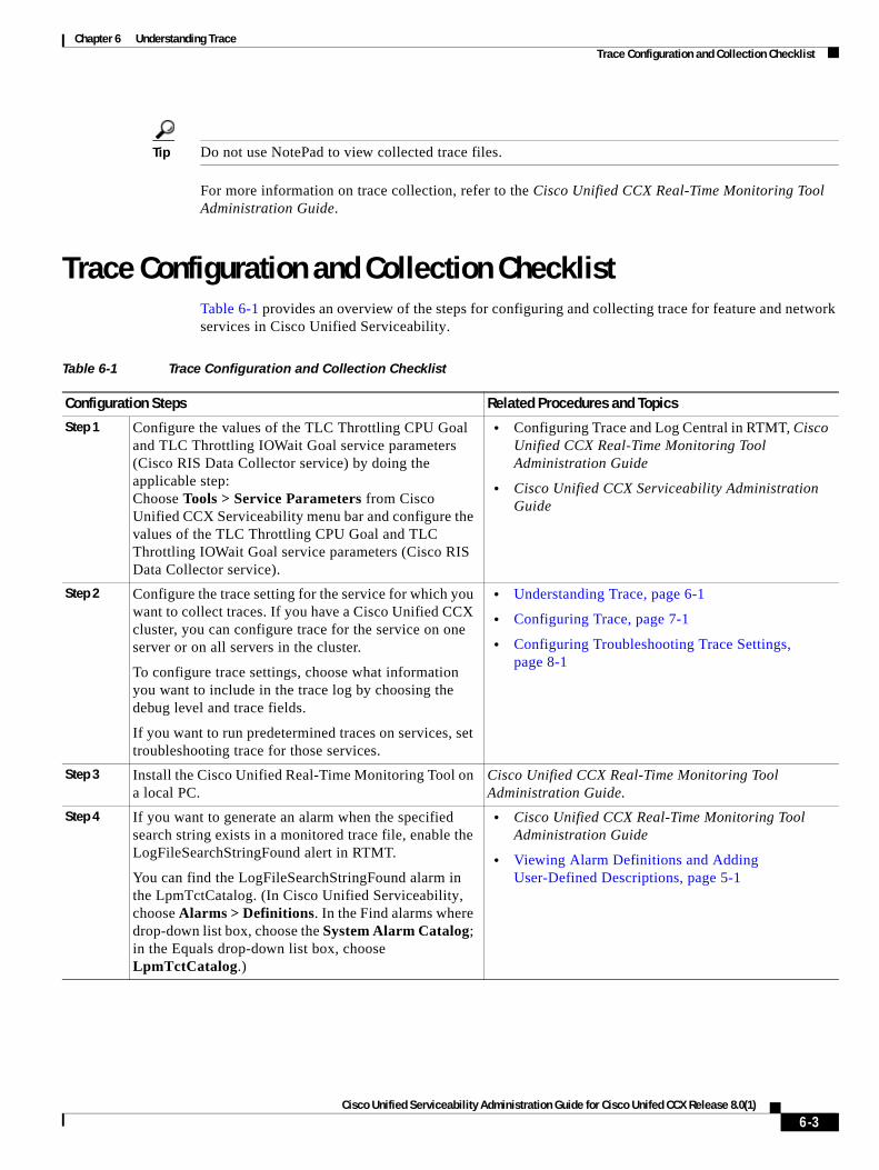
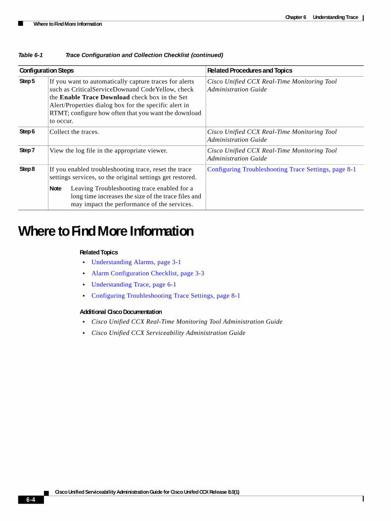
Trace Configuration and Collection ChecklistTable 6-1 provides an overview of the steps for configuring and collecting trace for feature and network services in Cisco Unified Serviceability.
Table 6-1 Trace Configuration and Collection Checklist
Configuration Steps Related Procedures and Topics
Step 1 Configure the values of the TLC Throttling CPU Goal and TLC Throttling IOWait Goal service parameters (Cisco RIS Data Collector service) by doing the applicable step: Choose Tools > Service Parameters from Cisco Unified CCX Serviceability menu bar and configure the values of the TLC Throttling CPU Goal and TLC Throttling IOWait Goal service parameters (Cisco RIS Data Collector service).
• Configuring Trace and Log Central in RTMT, Cisco Unified CCX Real-Time Monitoring Tool Administration Guide
• Cisco Unified CCX Serviceability Administration Guide
Step 2 Configure the trace setting for the service for which you want to collect traces. If you have a Cisco Unified CCX cluster, you can configure trace for the service on one server or on all servers in the cluster.
To configure trace settings, choose what information you want to include in the trace log by choosing the debug level and trace fields.
If you want to run predetermined traces on services, set troubleshooting trace for those services.
• Understanding Trace, page 6-1
• Configuring Trace, page 7-1
• Configuring Troubleshooting Trace Settings, page 8-1
Step 3 Install the Cisco Unified Real-Time Monitoring Tool on a local PC.
Cisco Unified CCX Real-Time Monitoring Tool Administration Guide.
Step 4 If you want to generate an alarm when the specified search string exists in a monitored trace file, enable the LogFileSearchStringFound alert in RTMT.
You can find the LogFileSearchStringFound alarm in the LpmTctCatalog. (In Cisco Unified Serviceability, choose Alarms > Definitions. In the Find alarms where drop-down list box, choose the System Alarm Catalog; in the Equals drop-down list box, choose LpmTctCatalog.)
• Cisco Unified CCX Real-Time Monitoring Tool Administration Guide
• Viewing Alarm Definitions and Adding User-Defined Descriptions, page 5-1
6-3Cisco Unified Serviceability Administration Guide for Cisco Unifed CCX Release 8.0(1)
Chapter 6 Understanding Trace Where to Find More Information
Where to Find More InformationRelated Topics
• Understanding Alarms, page 3-1
• Alarm Configuration Checklist, page 3-3
• Understanding Trace, page 6-1
• Configuring Troubleshooting Trace Settings, page 8-1
Additional Cisco Documentation
• Cisco Unified CCX Real-Time Monitoring Tool Administration Guide
• Cisco Unified CCX Serviceability Administration Guide
Step 5 If you want to automatically capture traces for alerts such as CriticalServiceDownand CodeYellow, check the Enable Trace Download check box in the Set Alert/Properties dialog box for the specific alert in RTMT; configure how often that you want the download to occur.
Cisco Unified CCX Real-Time Monitoring Tool Administration Guide
Step 6 Collect the traces. Cisco Unified CCX Real-Time Monitoring Tool Administration Guide
Step 7 View the log file in the appropriate viewer. Cisco Unified CCX Real-Time Monitoring Tool Administration Guide
Step 8 If you enabled troubleshooting trace, reset the trace settings services, so the original settings get restored.
Note Leaving Troubleshooting trace enabled for a long time increases the size of the trace files and may impact the performance of the services.
Configuring Troubleshooting Trace Settings, page 8-1
Table 6-1 Trace Configuration and Collection Checklist (continued)
Configuration Steps Related Procedures and Topics
6-4Cisco Unified Serviceability Administration Guide for Cisco Unifed CCX Release 8.0(1)
Cisco Unified Serviceability Admin
C H A P T E R 7
Configuring TraceNote Enabling trace decreases system performance; therefore, enable trace only for troubleshooting purposes. For assistance in using trace, contact your technical support team.
This chapter contains the following topics:
• Configuring Trace Parameters, page 7-1
• Service Groups in Trace Configuration, page 7-3
• Debug Trace Level Settings, page 7-4
• Trace Field Descriptions, page 7-5
• Trace Output Settings Descriptions and Defaults, page 7-6
• Where to Find More Information, page 7-7
Configuring Trace ParametersThis section describes how to configure trace parameters for feature and network services that you manage through Cisco Unified Serviceability.
Tip For Cisco Unified CCX, you may need to run trace in Cisco Unified Serviceability and Cisco Unified CCX Serviceability to troubleshoot Cisco Unified CCX issues. To troubleshoot services that are supported in Cisco Unified Serviceability, you run trace in Cisco Unified Serviceability. Similarly, to troubleshoot Cisco Unified CCX components, you run trace in Cisco Unified CCX Serviceability. For information on how to run trace in Cisco Unified CCX, refer to the Cisco Unified CCX Serviceability Administration Guide.
Procedure
Step 1 Choose Trace > Configuration.
The Trace Configuration window displays.
Step 2 From the Server drop-down list box, choose the server that is running the service for which you want to configure trace; then, click Go.
7-1istration Guide for Cisco Unifed CCX Release 8.0(1)
Chapter 7 Configuring Trace Configuring Trace Parameters
Step 3 From the Service Group drop-down list box, choose the service group for the service that you want to configure trace; then, click Go.
Tip Table 7-1 lists the services and trace libraries that correspond to the options that display in the Service Group drop-down list box.
Step 4 From the Service drop-down list box, choose the service for which you want to configure trace; then, click Go.
The drop-down list box displays active and inactive services.
If you configured Troubleshooting Trace for the service, a message displays at the top of the window that indicates that the Troubleshooting Traces feature is set, which means that the system disables all fields in the Trace Configuration window except for Trace Output Settings. To configure the Trace Output Settings, go to Step 10. To reset Troubleshooting Trace, see the “Configuring Troubleshooting Trace Settings” section on page 8-1.
The trace parameters display for the service that you chose. In addition, the Apply to All Nodes check box displays.
Step 5 If you have a Cisco Unified CCX cluster, you can apply the trace settings for the service or trace library to all servers in the cluster by checking the Apply to All Nodes check box.
Step 6 Check the Trace On check box.
Step 7 From the Debug Trace Level drop-down list box, choose the level of information that you want traced, as described in “Debug Trace Level Settings” section on page 7-4.
Step 8 Check the Trace Fields check box for the service that you chose; for example, Cisco Log Partition Monitoring Tool Trace Fields.
Step 9 If the service does not have multiple trace settings where you can specify the traces that you want to activate, check the Enable All Trace check box. If the service that you chose has multiple trace settings, check the check boxes next to the trace check boxes that you want to enable, as described in Trace Field Descriptions, page 7-5.
Step 10 To limit the number and size of the trace files, specify the trace output setting. See Table 7-6 for descriptions and default values.
Step 11 To save your trace parameters configuration, click the Save button.
The changes to trace configuration take effect immediately for all services. To set the default, click the Set Default button.
Additional Information
See the “Related Topics” section on page 7-7.
7-2Cisco Unified Serviceability Administration Guide for Cisco Unifed CCX Release 8.0(1)
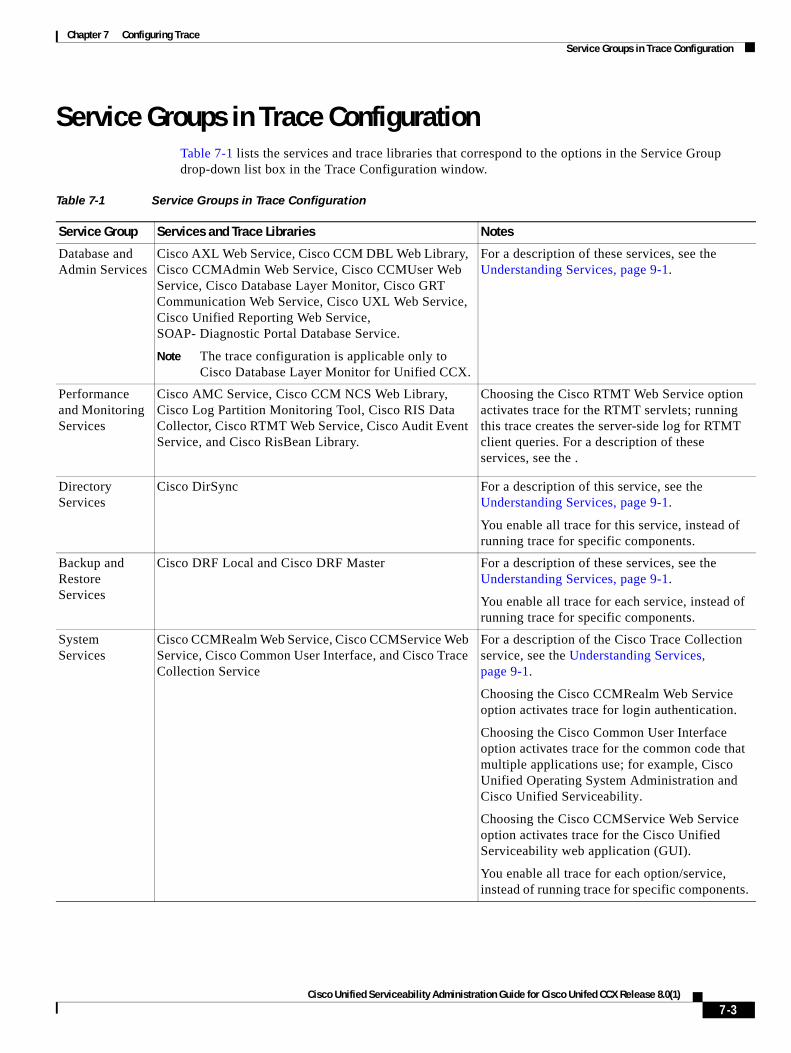
Chapter 7 Configuring Trace Service Groups in Trace Configuration
Service Groups in Trace ConfigurationTable 7-1 lists the services and trace libraries that correspond to the options in the Service Group drop-down list box in the Trace Configuration window.
Table 7-1 Service Groups in Trace Configuration
Service Group Services and Trace Libraries Notes
Database and Admin Services
Cisco AXL Web Service, Cisco CCM DBL Web Library, Cisco CCMAdmin Web Service, Cisco CCMUser Web Service, Cisco Database Layer Monitor, Cisco GRT Communication Web Service, Cisco UXL Web Service, Cisco Unified Reporting Web Service, SOAP- Diagnostic Portal Database Service.
Note The trace configuration is applicable only to Cisco Database Layer Monitor for Unified CCX.
For a description of these services, see the Understanding Services, page 9-1.
Performance and Monitoring Services
Cisco AMC Service, Cisco CCM NCS Web Library, Cisco Log Partition Monitoring Tool, Cisco RIS Data Collector, Cisco RTMT Web Service, Cisco Audit Event Service, and Cisco RisBean Library.
Choosing the Cisco RTMT Web Service option activates trace for the RTMT servlets; running this trace creates the server-side log for RTMT client queries. For a description of these services, see the .
Directory Services
Cisco DirSync For a description of this service, see the Understanding Services, page 9-1.
You enable all trace for this service, instead of running trace for specific components.
Backup and Restore Services
Cisco DRF Local and Cisco DRF Master For a description of these services, see the Understanding Services, page 9-1.
You enable all trace for each service, instead of running trace for specific components.
System Services
Cisco CCMRealm Web Service, Cisco CCMService Web Service, Cisco Common User Interface, and Cisco Trace Collection Service
For a description of the Cisco Trace Collection service, see the Understanding Services, page 9-1.
Choosing the Cisco CCMRealm Web Service option activates trace for login authentication.
Choosing the Cisco Common User Interface option activates trace for the common code that multiple applications use; for example, Cisco Unified Operating System Administration and Cisco Unified Serviceability.
Choosing the Cisco CCMService Web Service option activates trace for the Cisco Unified Serviceability web application (GUI).
You enable all trace for each option/service, instead of running trace for specific components.
7-3Cisco Unified Serviceability Administration Guide for Cisco Unifed CCX Release 8.0(1)
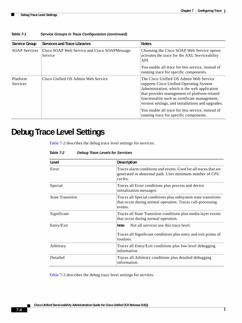
Chapter 7 Configuring Trace Debug Trace Level Settings
Debug Trace Level SettingsTable 7-2 describes the debug trace level settings for services.
Table 7-3 describes the debug trace level settings for servlets.
SOAP Services Cisco SOAP Web Service and Cisco SOAPMessage Service
Choosing the Cisco SOAP Web Service option activates the trace for the AXL Serviceability API.
You enable all trace for this service, instead of running trace for specific components.
Platform Services
Cisco Unified OS Admin Web Service The Cisco Unified OS Admin Web Service supports Cisco Unified Operating System Administration, which is the web application that provides management of platform-related functionality such as certificate management, version settings, and installations and upgrades.
You enable all trace for this service, instead of running trace for specific components.
Table 7-1 Service Groups in Trace Configuration (continued)
Service Group Services and Trace Libraries Notes
Table 7-2 Debug Trace Levels for Services
Level Description
Error Traces alarm conditions and events. Used for all traces that are generated in abnormal path. Uses minimum number of CPU cycles.
Special Traces all Error conditions plus process and device initialization messages.
State Transition Traces all Special conditions plus subsystem state transitions that occur during normal operation. Traces call-processing events.
Significant Traces all State Transition conditions plus media layer events that occur during normal operation.
Entry/Exit Note Not all services use this trace level.
Traces all Significant conditions plus entry and exit points of routines.
Arbitrary Traces all Entry/Exit conditions plus low-level debugging information.
Detailed Traces all Arbitrary conditions plus detailed debugging information.
7-4Cisco Unified Serviceability Administration Guide for Cisco Unifed CCX Release 8.0(1)
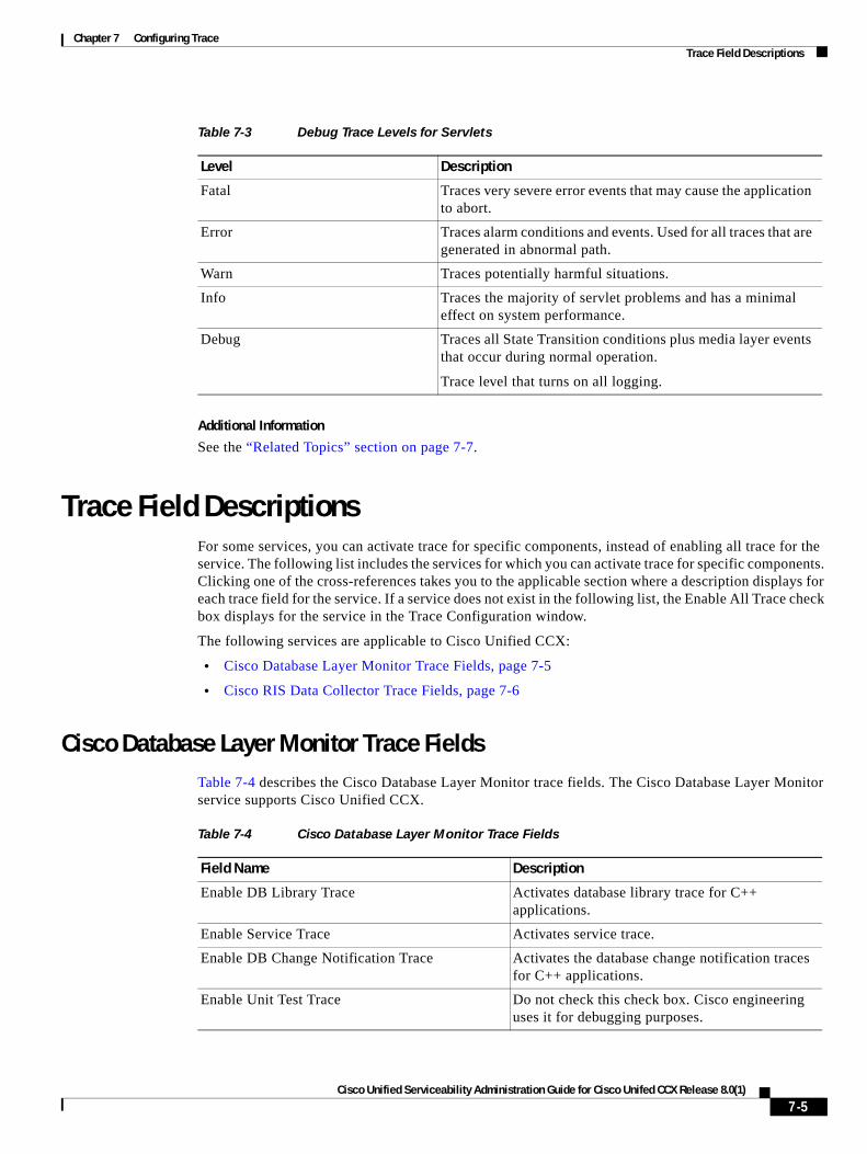
Chapter 7 Configuring Trace Trace Field Descriptions
Additional Information
See the “Related Topics” section on page 7-7.
Trace Field DescriptionsFor some services, you can activate trace for specific components, instead of enabling all trace for the service. The following list includes the services for which you can activate trace for specific components. Clicking one of the cross-references takes you to the applicable section where a description displays for each trace field for the service. If a service does not exist in the following list, the Enable All Trace check box displays for the service in the Trace Configuration window.
The following services are applicable to Cisco Unified CCX:
• Cisco Database Layer Monitor Trace Fields, page 7-5
• Cisco RIS Data Collector Trace Fields, page 7-6
Cisco Database Layer Monitor Trace FieldsTable 7-4 describes the Cisco Database Layer Monitor trace fields. The Cisco Database Layer Monitor service supports Cisco Unified CCX.
Table 7-3 Debug Trace Levels for Servlets
Level Description
Fatal Traces very severe error events that may cause the application to abort.
Error Traces alarm conditions and events. Used for all traces that are generated in abnormal path.
Warn Traces potentially harmful situations.
Info Traces the majority of servlet problems and has a minimal effect on system performance.
Debug Traces all State Transition conditions plus media layer events that occur during normal operation.
Trace level that turns on all logging.
Table 7-4 Cisco Database Layer Monitor Trace Fields
Field Name Description
Enable DB Library Trace Activates database library trace for C++ applications.
Enable Service Trace Activates service trace.
Enable DB Change Notification Trace Activates the database change notification traces for C++ applications.
Enable Unit Test Trace Do not check this check box. Cisco engineering uses it for debugging purposes.
7-5Cisco Unified Serviceability Administration Guide for Cisco Unifed CCX Release 8.0(1)
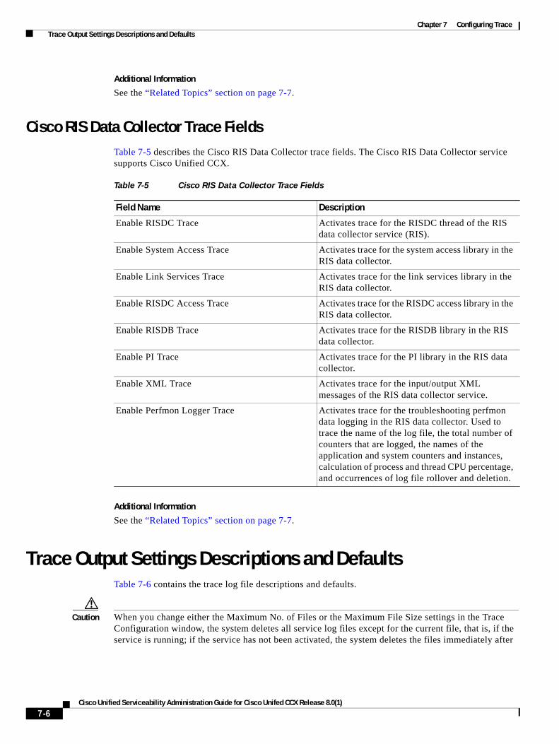
Chapter 7 Configuring Trace Trace Output Settings Descriptions and Defaults
Additional Information
See the “Related Topics” section on page 7-7.
Cisco RIS Data Collector Trace FieldsTable 7-5 describes the Cisco RIS Data Collector trace fields. The Cisco RIS Data Collector service supports Cisco Unified CCX.
Additional Information
See the “Related Topics” section on page 7-7.
Trace Output Settings Descriptions and DefaultsTable 7-6 contains the trace log file descriptions and defaults.
Caution When you change either the Maximum No. of Files or the Maximum File Size settings in the Trace Configuration window, the system deletes all service log files except for the current file, that is, if the service is running; if the service has not been activated, the system deletes the files immediately after
Table 7-5 Cisco RIS Data Collector Trace Fields
Field Name Description
Enable RISDC Trace Activates trace for the RISDC thread of the RIS data collector service (RIS).
Enable System Access Trace Activates trace for the system access library in the RIS data collector.
Enable Link Services Trace Activates trace for the link services library in the RIS data collector.
Enable RISDC Access Trace Activates trace for the RISDC access library in the RIS data collector.
Enable RISDB Trace Activates trace for the RISDB library in the RIS data collector.
Enable PI Trace Activates trace for the PI library in the RIS data collector.
Enable XML Trace Activates trace for the input/output XML messages of the RIS data collector service.
Enable Perfmon Logger Trace Activates trace for the troubleshooting perfmon data logging in the RIS data collector. Used to trace the name of the log file, the total number of counters that are logged, the names of the application and system counters and instances, calculation of process and thread CPU percentage, and occurrences of log file rollover and deletion.
7-6Cisco Unified Serviceability Administration Guide for Cisco Unifed CCX Release 8.0(1)
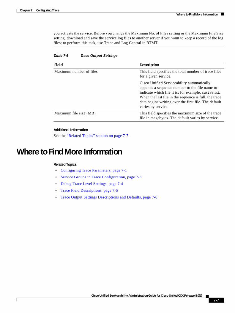
Chapter 7 Configuring Trace Where to Find More Information
you activate the service. Before you change the Maximum No. of Files setting or the Maximum File Size setting, download and save the service log files to another server if you want to keep a record of the log files; to perform this task, use Trace and Log Central in RTMT.
Additional Information
See the “Related Topics” section on page 7-7.
Where to Find More InformationRelated Topics
• Configuring Trace Parameters, page 7-1
• Service Groups in Trace Configuration, page 7-3
• Debug Trace Level Settings, page 7-4
• Trace Field Descriptions, page 7-5
• Trace Output Settings Descriptions and Defaults, page 7-6
Table 7-6 Trace Output Settings
Field Description
Maximum number of files This field specifies the total number of trace files for a given service.
Cisco Unified Serviceability automatically appends a sequence number to the file name to indicate which file it is; for example, cus299.txt. When the last file in the sequence is full, the trace data begins writing over the first file. The default varies by service.
Maximum file size (MB) This field specifies the maximum size of the trace file in megabytes. The default varies by service.
7-7Cisco Unified Serviceability Administration Guide for Cisco Unifed CCX Release 8.0(1)

Chapter 7 Configuring Trace Where to Find More Information
7-8Cisco Unified Serviceability Administration Guide for Cisco Unifed CCX Release 8.0(1)
Cisco Unified Serviceability Admin
C H A P T E R 8
Configuring Troubleshooting Trace SettingsThe Troubleshooting Trace Settings window allows you to choose the services for which you want to set predetermined troubleshooting trace settings. This chapter contains information on how to set and reset troubleshooting trace settings for services that exist in Cisco Unified Serviceability.
Note Leaving Troubleshooting Trace enabled for a long time increases the size of the trace files and may impact the performance of the services.
Procedure
Step 1 In Cisco Unified Serviceability, choose Trace > Troubleshooting Trace Settings.
Step 2 From the Server drop-down list box, choose the server where you want to troubleshoot trace settings; then, click Go.
Note A list of services displays. The services that are not activated display as N/A.
Step 3 Perform one of the following tasks:
• To check specific services for the server that you chose in the Server drop-down list box, check the service(s) check box(es) in the Services pane; for example, the Database and Admin Services, Performance and Monitoring Services, or the Backup and Restore Services pane (and so on).
This task affects only the server that you chose in the Server drop-down list box.
• Check one of the following check boxes:
– Check All Services—Automatically checks all check boxes for the services on the current server that you chose in the Server drop-down list box.
– Check Selected Services on All Nodes—Allows you to check specific service check boxes in the Troubleshooting Trace Setting window. This setting applies for all servers in the cluster where the service is activated.
– Check All Services on All Nodes —Automatically checks all check boxes for all services for all servers in the cluster. When you check this check box, the Check All Services and Check Selected Services on All Nodes check boxes automatically get checked.
Step 4 Click the Save button.
Step 5 After you configure troubleshooting trace for one or more services, you can restore the original trace settings. If you want to restore the original trace settings, click one of the following buttons:
8-1istration Guide for Cisco Unifed CCX Release 8.0(1)
Chapter 8 Configuring Troubleshooting Trace Settings Where to Find More Information
• Reset Troubleshooting Traces—Restores the original trace settings for the services on the server that you chose in the Server drop-down list box; also displays as an icon that you can click.
After you click the reset button, the window refreshes, and the service check boxes display as unchecked.
Additional Information
See the “Related Topics” section on page 8-2.
Where to Find More InformationRelated Topics
• Configuring Trace, page 7-1
• Understanding Trace, page 6-1
8-2Cisco Unified Serviceability Administration Guide for Cisco Unifed CCX Release 8.0(1)

P A R T 4
Tools

Cisco Unified Serviceability Admin
C H A P T E R 9
Understanding ServicesCisco Unified Serviceability service management includes working with feature and network services and servlets, which are associated with the Tomcat Java Webserver. Feature services allow you to use application features, such as Serviceability Reports Archive, while network services are required for your system to function.
If something is wrong with a service or servlet, an alarm gets written to an alarm monitor. After viewing the alarm information, you can run a trace on the service. Be aware that services and servlets display different trace levels in the Trace Configuration window.
This chapter, which provides a description of services/servlets, Service Activation, and Control Center, contains information on the following topics:
• Feature Services, page 9-1
• Network Services, page 9-2
• Service Activation, page 9-7
• Control Center, page 9-7
• Services Configuration Checklist, page 9-8
• Where to Find More Information, page 9-8
Feature ServicesIn Cisco Unified Serviceability, you can activate, start, and stop feature services. Activation turns on and starts the service. After you activate a service in the Service Activation window, you do not need to start it in the Control Center—Feature Services window. If the service does not start for any reason, you must start it in the Control Center—Features Services window.
After the system is installed, it does not automatically activate feature services, which are related services that are required if you want to use your configuration features; for example, the Serviceability Reports Archive feature.
After you activate feature services, you can modify associated settings in Cisco Unified CCX Serviceability.
If you are upgrading Cisco Unified CCX, those services that you activated on the system prior to the upgrade automatically activate and start after the upgrade.
In the Service Activation window, Cisco Unified Serviceability categorizes feature services into the following groups:
• Database and Admin Services, page 9-2
9-1istration Guide for Cisco Unifed CCX Release 8.0(1)
Chapter 9 Understanding Services Network Services
• Performance and Monitoring Services, page 9-2
• Directory Services, page 9-2
In the Control Center—Feature Services window, Cisco Unified Serviceability categorizes services into the same groups that display in the Service Activation window.
Tip For service activation recommendations, see the “Service Activation” section on page 9-7 and the “Activating and Deactivating Feature Services” section on page 11-1.
Database and Admin ServicesThe following Database and Admin Services are not applicable for Unified CCX.
• Cisco AXL Web Service
• Cisco UXL Web Service
Performance and Monitoring ServicesThis section describes the Performance Monitoring Services.
Cisco Serviceability Reporter
The Cisco Serviceability Reporter service generates the daily reports that are described in “Understanding Serviceability Reports Archive” section on page 10-1.
In a Cisco Unified CCX cluster, this service gets installed on both the nodes in the cluster. Reporter generates reports once a day based on logged information. You can access the reports that Reporter generates in Cisco Unified Serviceability from the Tools menu. Each summary report comprises different charts that display the statistics for that particular report. After you activate the service, report generation may take up to 24 hours.
Directory ServicesThe Cisco DirSynch directory services is not applicable for Unified CCX.
Network ServicesInstalled automatically, network services include services that the system requires to function; for example, database and platform services. Because these services are required for basic functionality, you cannot activate them in the Service Activation window. If necessary, for example, for troubleshooting purposes, you may need to stop and start (or restart) a network service in the Call Control—Network Services window.
After the installation of your application, network services start automatically, as noted in the Call Control—Network Services window. In the Control Center—Network Services window, Cisco Unified Serviceability categorizes services into the following groups:
• Performance and Monitoring Services, page 9-3
• Backup and Restore Services, page 9-4
9-2Cisco Unified Serviceability Administration Guide for Cisco Unifed CCX Release 8.0(1)
Chapter 9 Understanding Services Network Services
• System Services, page 9-4
• Platform Services, page 9-5
• Security Services, page 9-6
• DB Services, page 9-6
• SOAP Services, page 9-6
Performance and Monitoring ServicesThis section describes the Performance and Monitoring Services.
Cisco Unified Serviceability RTMT
The Cisco Unified Serviceability RTMT servlet supports the Cisco Unified CCX Real-Time Monitoring Tool (RTMT), which allows you to collect and view traces, view performance monitoring objects, work with alerts, and monitor devices, system performance, CTI applications, and so on.
Cisco RTMT Reporter Servlet
The Cisco RTMT Reporter servlet allows you to publish reports for RTMT.
Cisco Log Partition Monitoring Tool
The Cisco Log Partition Monitoring Tool service supports the Log Partition Monitoring feature, which monitors the disk usage of the log partition on a server (or all servers in the cluster) by using configured thresholds and a polling interval.
Cisco Tomcat Stats Servlet
The Cisco Tomcat Stats Servlet allows you to monitor the Tomcat perfmon counters by using RTMT or the Command Line Interface. Do not stop this service unless you suspect that this service is using too many resources, such as CPU time.
Cisco RIS Data Collector
The Real-time Information Server (RIS) maintains real-time information such as device registration status, performance counter statistics, critical alarms generated, and so on. The Cisco RIS Data Collector service provides an interface for applications, such as the Cisco Unified CCX Real-Time Monitoring Tool (RTMT), SOAP applications, and so on, to retrieve the information that is stored in the RIS server (or in all RIS servers in the cluster).
Cisco AMC Service
Used for the Cisco Unified CCX Real-Time Monitoring Tool (RTMT), this service, Alert Manager and Collector service, allows RTMT to retrieve real-time information that exists on the server (or on all servers in the cluster).
Cisco Audit Event Service
The Cisco Audit Event Service monitors and logs any configuration change to the Cisco Unified CCX system by a user or as a result of the user action.
Cisco RisBean Library
Cisco RisBean Library comprises a library that some webapps use to communicate with other internal services.
9-3Cisco Unified Serviceability Administration Guide for Cisco Unifed CCX Release 8.0(1)
Chapter 9 Understanding Services Network Services
You should leave trace settings at default level unless you are instructed by TAC to change them to debug an issue.
Backup and Restore ServicesThis section describes the Backup and Restore Services.
Cisco DRF Master
The CiscoDRF Master Agent service supports the DRF Master Agent, which works with the Disaster Recovery System graphical user interface (GUI) or command line interface (CLI) to schedule backups, perform restorations, view dependencies, check status of jobs, and cancel jobs, if necessary. The Cisco DRF Master Agent also provides the storage medium for the backup and restoration process.
Cisco DRF Local
The Cisco DRF Local service supports the Cisco DRF Local Agent, which acts as the workhorse for the DRF Master Agent. Components register with the Cisco DRF Local Agent to use the disaster recovery framework. The Cisco DRF Local Agent executes commands that it receives from the Cisco DRF Master Agent. Cisco DRF Local Agent sends the status, logs, and command results to the Cisco DRF Master Agent.
System ServicesThis section describes the System Services.
Cisco Unified Serviceability
The Cisco CallManager Serviceability service supports Cisco Unified Serviceability, the web application/interface that you use to troubleshoot issues and manage services. This service, which is installed automatically, allows you access to the Cisco Unified Serviceability graphical user interface (GUI). If you stop this service, you cannot access the Cisco Unified Serviceability GUI when you browse into that server.
Cisco CDP
Cisco CDP advertises the voice application to other network management applications, so the network management application, for example, SNMP or CiscoWorks Lan Management Solution, can perform network management tasks for the voice application.
Cisco Trace Collection Servlet
The Cisco Trace Collection Servlet, along with the Cisco Trace Collection Service, supports trace collection and allows users to view traces by using RTMT. If you stop this service on a server, you cannot collect or view traces on that server.
For SysLog Viewer and Trace and Log Central to work in RTMT, the Cisco Trace Collection Servlet and the Cisco Trace Collection Service must run on the server.
Cisco Trace Collection Service
The Cisco Trace Collection Service, along with the Cisco Trace Collection Servlet, supports trace collection and allows users to view traces by using the RTMT client. If you stop this service on a server, you cannot collect or view traces on that server.
9-4Cisco Unified Serviceability Administration Guide for Cisco Unifed CCX Release 8.0(1)
Chapter 9 Understanding Services Network Services
For SysLog Viewer and Trace and Log Central to work in RTMT, the Cisco Trace Collection Servlet and the Cisco Trace Collection Service must run on the server.
Tip If necessary, Cisco recommends that, to reduce the initialization time, you restart the Cisco Trace Collection Service before restarting Cisco Trace Collection Servlet.
Platform ServicesThis section describes the Platform Services.
A Cisco DB
A Cisco DB service supports the Progres database engine.
A Cisco DB Replicator
The A Cisco DB Replicator service ensures database configuration and data synchronization between the primary and secondary Unified CCX servers in the cluster.
Cisco Tomcat
The Cisco Tomcat service supports the web server.
SNMP Master Agent
This service, which acts as the agent protocol engine, provides authentication, authorization, access control, and privacy functions that relate to SNMP requests.
Tip After you complete SNMP configuration in Cisco Unified Serviceability, you must restart the SNMP Master Agent service in the Control Center—Network Features window.
MIB2 Agent
This service provides SNMP access to variables, which are defined in RFC 1213, that read and write variables; for example, system, interfaces, IP, and so on.
Host Resources Agent
This service provides SNMP access to host information, such as storage resources, process tables, device information, and installed software base. This service implements the HOST-RESOURCES-MIB.
Native Agent Adaptor
This service, which supports vendor MIBs, allows you to forward SNMP requests to another SNMP agent that runs on the system.
System Application Agent
This service provides SNMP access to the applications that are installed and executing on the system. This implements the SYSAPPL-MIB.
Cisco CDP Agent
This service uses the Cisco Discovery Protocol to provide SNMP access to network connectivity information on the Cisco Unified CCX server. This service implements the CISCO-CDP-MIB.
9-5Cisco Unified Serviceability Administration Guide for Cisco Unifed CCX Release 8.0(1)
Chapter 9 Understanding Services Network Services
Cisco Syslog Agent
This service supports gathering of syslog messages that various components generate. This service implements the CISCO-SYSLOG-MIB.
Caution Stopping any SNMP service may result in loss of data because the network management system no longer monitors the network. Do not stop the services unless the your technical support team tells you to do so.
Cisco Certificate Expiry Monitor
This service periodically checks the expiration status of certificates that the system generates and sends notification when a certificate gets close to its expiration date. You manage the certificates that use this service in Cisco Unified Operating System Administration.
Security ServicesThis section describes the Security Services.
Cisco Trust Verification Service
Cisco Trust Verification Service is a service running on a Cisco Unified CCX server or a dedicated server, that authenticates certificates on behalf of phones and other endpoints. It associates a list of roles for the owner of the certificate. A certificate or the owner can be associated with one or many roles.
The protocol between phones and Trust Verification Service allows phones to request for verification. Trust Verification Service validates the certificate and returns a list of roles associated with it. The protocol allows Trust Verification Service to authenticate a request and conversely, a phone to authenticate the response from Trust Verification Service. The protocol protects the integrity of the request and the response. Confidentiality of the request and the response is not required.
Multiples instances of Cisco Trust Verification Service run on different servers in the cluster to provide scalability. These servers may or may not be the same as the ones hosting the Cisco Unified CallManager. Phones obtain a list of Trust Verification Services in the network and connect to one of them using a selection algorithm (example: Round Robin). If the contacted Trust Verification Service does not respond, the phone switches to the next Trust Verification Service in the list.
Note This service is not applicable for Unified CCX 8.0(1).
DB ServicesThis section describes the DB Services.
Cisco Database Layer Monitor
The Cisco Database Layer Monitor service monitors aspects of the database layer. This service takes responsibility for change notification and monitoring.
SOAP ServicesThis section describes the SOAP Services.
9-6Cisco Unified Serviceability Administration Guide for Cisco Unifed CCX Release 8.0(1)
Chapter 9 Understanding Services Service Activation
Cisco SOAP-Real-Time Service APIs
The Cisco SOAP-Real-Time Service APIs allow you to collect real-time information for devices and CTI applications. This service also provides APIs for activating, starting, and stopping services.
Cisco SOAP-Performance Monitoring APIs
The Cisco SOAP-Performance Monitoring APIs service allows you to use performance monitoring counters for various applications through SOAP APIs; for example, you can monitor memory information per service, CPU usage, performance monitoring counters, and so on.
Cisco SOAP-Log Collection APIs
The Cisco SOAP-Log Collection APIs service allows you to collect log files and to schedule collection of log files on a remote SFTP server. Examples of log files that you can collect include syslog, core dump files, Cisco application trace files, and so on.
Service ActivationYou can activate or deactivate multiple feature services or choose default services to activate from the Service Activation window in Cisco Unified Serviceability.
Cisco Unified Serviceability activates feature services in automatic mode and checks for service dependencies. When you choose to activate a feature service, Cisco Unified Serviceability prompts you to select all the other services, if any, that depend on that service to run. When you click the Set to Default button, Cisco Unified Serviceability chooses those services that are required to run on the server.
In a Cisco Unified CCX cluster, you need to do this process for each server. Activating a service automatically starts the service. You start/stop services from Control Center.
Control CenterFrom Control Center in Cisco Unified Serviceability, you can view status and start and stop one service at a time. In a cluster, you can perform these functions for one server in the cluster. To perform these tasks, Cisco Unified Serviceability provides two Control Center windows. To start, stop, and restart network services, access the Control Center—Network Services window. To start, stop, and restart feature services, access the Control Center—Feature Services window.
Tip Use the Related Links drop-down list box and the Go button to navigate to Control Center and Service Activation windows.
9-7Cisco Unified Serviceability Administration Guide for Cisco Unifed CCX Release 8.0(1)
Chapter 9 Understanding Services Services Configuration Checklist
Services Configuration ChecklistTable 9-1 lists the steps for working with services.
Where to Find More InformationRelated Topics
• Control Center, page 9-7
• Feature Services, page 9-1
• Network Services, page 9-2
Additional Cisco Documentation
• Cisco Unified CCX Serviceability Administration Guide
• Cisco Unified CCX Real-Time Monitoring Tool Administration Guide
Table 9-1 Services Configuration Checklist
Configuration Steps Procedures and Related Topics
Step 1 Activate the feature services that you want to run. • Feature Services, page 9-1
• Activating and Deactivating Feature Services, page 11-1
Step 2 Configure the appropriate service parameters. • You configure service parameters in Cisco Unified CCX Serviceability. For service parameter configuration, see the Cisco Unified CCX Serviceability Administration Guide.
Step 3 If necessary, troubleshoot problems by using the Cisco Unified Serviceability trace tools.
• Configuring Trace, page 7-1
• Cisco Unified CCX Real-Time Monitoring Tool Administration Guide
9-8Cisco Unified Serviceability Administration Guide for Cisco Unifed CCX Release 8.0(1)
Cisco Unified Serviceability Admin
C H A P T E R 10
Understanding Serviceability Reports ArchiveThe Cisco Serviceability Reporter service generates daily reports in Cisco Unified Serviceability. Each report provides a summary that comprises different charts that display the statistics for that particular report. Reporter generates reports once a day on the basis of logged information.
The following sections provide additional information, including detailed information about each report that Serviceability Reporter generates:
• Serviceability Reporter Service Parameters, page 10-2
• Server Statistics Report, page 10-2
• Alert Summary Report, page 10-4
• Serviceability Reports Archive Configuration Checklist, page 10-6
• Where to Find More Information, page 10-6
Note Because the Cisco Serviceability Reporter is only active on the primary Cisco Unified CCX server, at any time, Reporter generates reports only on the primary node and not the secondary node.
You can view reports from Cisco Unified Serviceability > Tools > Serviceability Reports Archive. You must activate the Cisco Serviceability Reporter service before you can view reports. After you activate the service, report generation may take up to 24 hours.
The reports contain 24-hour data for the previous day. A suffix that is added to the report names shows the date for which Reporter generated them; for example, AlertRep_mm_dd_yyyy.pdf. The Serviceability Reports Archive window uses this date to display the reports for the relevant date only. The reports generate from the data that is present in the log files, with the timestamp for the previous day. The system considers log files for the current date and the previous two days for collecting data. In a Cisco Unified CCX cluster, this takes into account the time zone differences between the server locations.
The time that is shown in the report reflects the server “System Time.” In a Unified CCX cluster configuration, the time that is shown in the report reflects the first server “System Time.” If the first server and subsequent server(s) are in different time zones, the first server “System Time” shows in the report.
Note You can pick up log files from the server while you are generating reports, or in a cluster configuration from both the nodes in the cluster.
10-1istration Guide for Cisco Unifed CCX Release 8.0(1)
Chapter 10 Understanding Serviceability Reports Archive Serviceability Reporter Service Parameters
Serviceability Reporter Service ParametersCisco Serviceability Reporter uses the following service parameters:
• RTMT Reporter Designated Node—Specifies the designated node on which RTMT Reporter runs. This default equals the IP address of the server on which the Cisco Serviceability Reporter service is first activated.
Because the Serviceability Reporter service is CPU intensive, Cisco recommends that you specify a non-call processing node.
• Report Generation Time—Specifies the number of minutes after midnight. Reports generate at this time for the most recent day. The minimum value equals 0 and the maximum value equals 1439.
• Report Deletion Age—Specifies the number of days that the report must be kept on the disk. The system deletes reports that are older than the specified age. The minimum value equals 0, and the maximum value equals 30.
Tip You can disable reports by setting the service parameter Report Deletion Age to a value of 0.
For more information about service parameter configuration, refer to Cisco Unified CCX Serviceability Administration Guide.
Server Statistics ReportThe Server Statistics Report provides the following line charts:
• Percentage of CPU per Server, page 10-2
• Percentage of Memory Usage per Server, page 10-3
• Percentage of Hard Disk Usage of the Largest Partition per Server, page 10-3
Percentage of CPU per Server
A line chart displays the percentage of CPU usage for the server (or for each server in a Cisco Unified CCX cluster). The line in the chart represents the data for the server (or one line for each server in a Cisco Unified CCX cluster) for which data is available. Each data value in the chart represents the average CPU usage for a 15-minute duration. If no data exists for the server (or for any one server in a Cisco Unified CCX cluster), Reporter does not generate the line that represents that server. If there are no lines to generate, Reporter does not create the chart. The message “No data for Server Statistics report available” displays.
Figure 10-1 shows a line chart example that represents the percentage of CPU usage per server in a Cisco Unified CCX cluster configuration.
10-2Cisco Unified Serviceability Administration Guide for Cisco Unifed CCX Release 8.0(1)
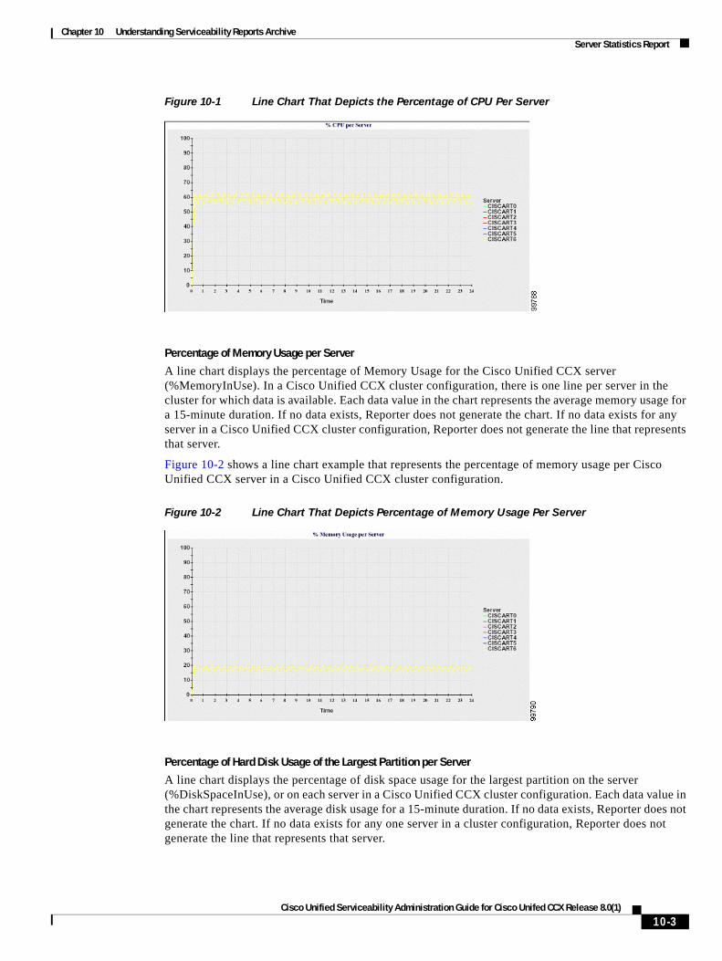
Chapter 10 Understanding Serviceability Reports Archive Server Statistics Report
Figure 10-1 Line Chart That Depicts the Percentage of CPU Per Server
Percentage of Memory Usage per Server
A line chart displays the percentage of Memory Usage for the Cisco Unified CCX server (%MemoryInUse). In a Cisco Unified CCX cluster configuration, there is one line per server in the cluster for which data is available. Each data value in the chart represents the average memory usage for a 15-minute duration. If no data exists, Reporter does not generate the chart. If no data exists for any server in a Cisco Unified CCX cluster configuration, Reporter does not generate the line that represents that server.
Figure 10-2 shows a line chart example that represents the percentage of memory usage per Cisco Unified CCX server in a Cisco Unified CCX cluster configuration.
Figure 10-2 Line Chart That Depicts Percentage of Memory Usage Per Server
Percentage of Hard Disk Usage of the Largest Partition per Server
A line chart displays the percentage of disk space usage for the largest partition on the server (%DiskSpaceInUse), or on each server in a Cisco Unified CCX cluster configuration. Each data value in the chart represents the average disk usage for a 15-minute duration. If no data exists, Reporter does not generate the chart. If no data exists for any one server in a cluster configuration, Reporter does not generate the line that represents that server.
10-3Cisco Unified Serviceability Administration Guide for Cisco Unifed CCX Release 8.0(1)
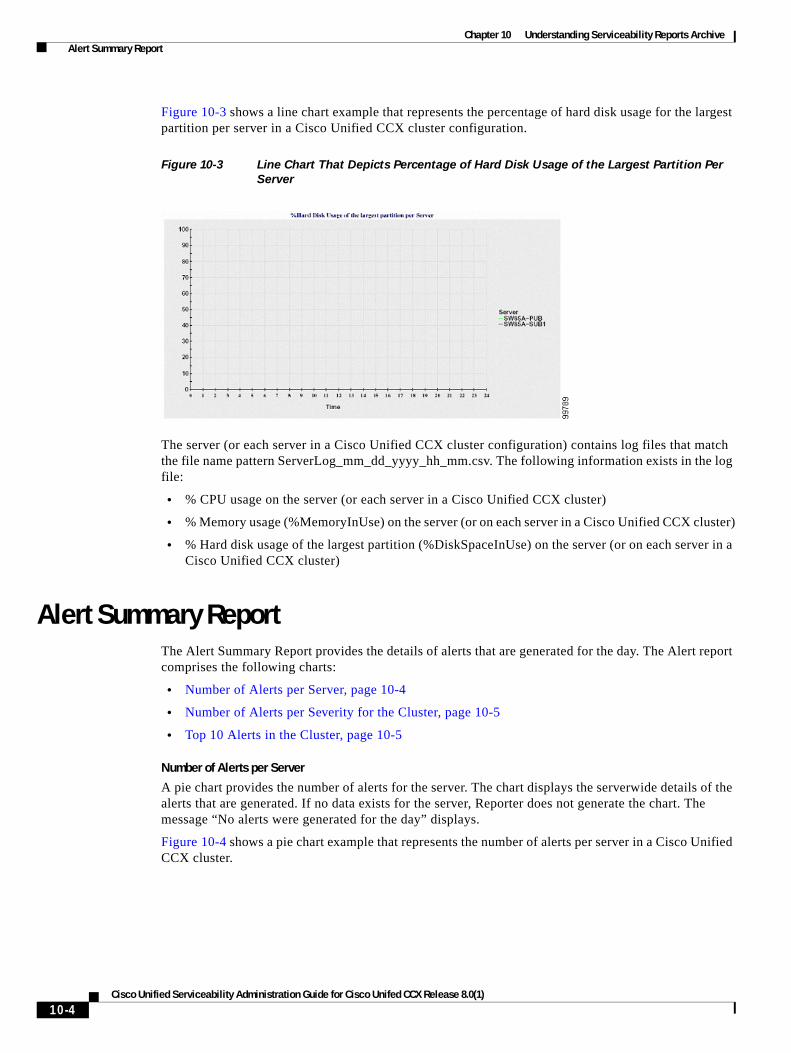
Chapter 10 Understanding Serviceability Reports Archive Alert Summary Report
Figure 10-3 shows a line chart example that represents the percentage of hard disk usage for the largest partition per server in a Cisco Unified CCX cluster configuration.
Figure 10-3 Line Chart That Depicts Percentage of Hard Disk Usage of the Largest Partition Per
Server
The server (or each server in a Cisco Unified CCX cluster configuration) contains log files that match the file name pattern ServerLog_mm_dd_yyyy_hh_mm.csv. The following information exists in the log file:
• % CPU usage on the server (or each server in a Cisco Unified CCX cluster)
• % Memory usage (%MemoryInUse) on the server (or on each server in a Cisco Unified CCX cluster)
• % Hard disk usage of the largest partition (%DiskSpaceInUse) on the server (or on each server in a Cisco Unified CCX cluster)
Alert Summary ReportThe Alert Summary Report provides the details of alerts that are generated for the day. The Alert report comprises the following charts:
• Number of Alerts per Server, page 10-4
• Number of Alerts per Severity for the Cluster, page 10-5
• Top 10 Alerts in the Cluster, page 10-5
Number of Alerts per Server
A pie chart provides the number of alerts for the server. The chart displays the serverwide details of the alerts that are generated. If no data exists for the server, Reporter does not generate the chart. The message “No alerts were generated for the day” displays.
Figure 10-4 shows a pie chart example that represents the number of alerts per server in a Cisco Unified CCX cluster.
10-4Cisco Unified Serviceability Administration Guide for Cisco Unifed CCX Release 8.0(1)
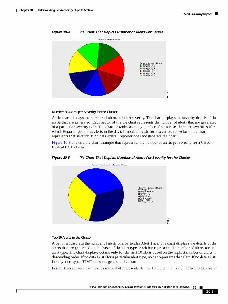
Chapter 10 Understanding Serviceability Reports Archive Alert Summary Report
Figure 10-4 Pie Chart That Depicts Number of Alerts Per Server
Number of Alerts per Severity for the Cluster
A pie chart displays the number of alerts per alert severity. The chart displays the severity details of the alerts that are generated. Each sector of the pie chart represents the number of alerts that are generated of a particular severity type. The chart provides as many number of sectors as there are severities (for which Reporter generates alerts in the day). If no data exists for a severity, no sector in the chart represents that severity. If no data exists, Reporter does not generate the chart.
Figure 10-5 shows a pie chart example that represents the number of alerts per severity for a Cisco Unified CCX cluster.
Figure 10-5 Pie Chart That Depicts Number of Alerts Per Severity for the Cluster
Top 10 Alerts in the Cluster
A bar chart displays the number of alerts of a particular Alert Type. The chart displays the details of the alerts that are generated on the basis of the alert type. Each bar represents the number of alerts for an alert type. The chart displays details only for the first 10 alerts based on the highest number of alerts in descending order. If no data exists for a particular alert type, no bar represents that alert. If no data exists for any alert type, RTMT does not generate the chart.
Figure 10-6 shows a bar chart example that represents the top 10 alerts in a Cisco Unified CCX cluster.
10-5Cisco Unified Serviceability Administration Guide for Cisco Unifed CCX Release 8.0(1)
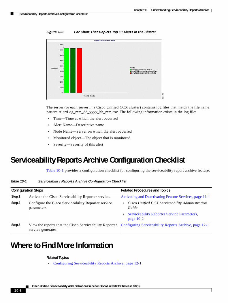
Chapter 10 Understanding Serviceability Reports Archive Serviceability Reports Archive Configuration Checklist
Figure 10-6 Bar Chart That Depicts Top 10 Alerts in the Cluster
The server (or each server in a Cisco Unified CCX cluster) contains log files that match the file name pattern AlertLog_mm_dd_yyyy_hh_mm.csv. The following information exists in the log file:
• Time—Time at which the alert occurred
• Alert Name—Descriptive name
• Node Name—Server on which the alert occurred
• Monitored object—The object that is monitored
• Severity—Severity of this alert
Serviceability Reports Archive Configuration ChecklistTable 10-1 provides a configuration checklist for configuring the serviceability report archive feature.
Where to Find More InformationRelated Topics
• Configuring Serviceability Reports Archive, page 12-1
Table 10-1 Serviceability Reports Archive Configuration Checklist
Configuration Steps Related Procedures and Topics
Step 1 Activate the Cisco Serviceability Reporter service. Activating and Deactivating Feature Services, page 11-1
Step 2 Configure the Cisco Serviceability Reporter service parameters.
• Cisco Unified CCX Serviceability Administration Guide
• Serviceability Reporter Service Parameters, page 10-2
Step 3 View the reports that the Cisco Serviceability Reporter service generates.
Configuring Serviceability Reports Archive, page 12-1
10-6Cisco Unified Serviceability Administration Guide for Cisco Unifed CCX Release 8.0(1)

Chapter 10 Understanding Serviceability Reports Archive Where to Find More Information
Additional Cisco Documentation
• Cisco Unified CCX Serviceability Administration Guide
• Cisco Unified CCX Real-Time Monitoring Tool Administration Guide
10-7Cisco Unified Serviceability Administration Guide for Cisco Unifed CCX Release 8.0(1)

Chapter 10 Understanding Serviceability Reports Archive Where to Find More Information
10-8Cisco Unified Serviceability Administration Guide for Cisco Unifed CCX Release 8.0(1)
Cisco Unified Serviceability Admin
C H A P T E R 11
Configuring ServicesThis chapter contains information on the following topics:
• Activating and Deactivating Feature Services, page 11-1
• Cluster Service Activation Recommendations, page 11-2
• Starting, Stopping, Restarting, and Refreshing Status of Services in Control Center, page 11-3
• Using a Command Line Interface to Start and Stop Services, page 11-4
Activating and Deactivating Feature ServicesYou activate and deactivate feature services in the Service Activation window in Cisco Unified Serviceability. Services that display in the Service Activation window do not start until you activate them.
Cisco Unified Serviceability allows you to activate and deactivate only features services (not network services). You may activate or deactivate as many services as you want at the same time. Some feature services depend on other services, and the dependent services get activated before the feature service activates.
Tip Before you activate services in the Service Activation window, review Table 11-1.
To activate or deactivate feature services in Cisco Unified Serviceability, perform the following procedure:
Procedure
Step 1 Choose Tools > Service Activation.
The Service Activation window displays.
Step 2 From the Server drop-down list box, choose the server where you want to activate the service; then, click Go.
For the server that you chose, the window displays the service names and the activation status of the services.
Step 3 To activate all services in the Service Activation window, check the Check All Services check box.
11-1istration Guide for Cisco Unifed CCX Release 8.0(1)
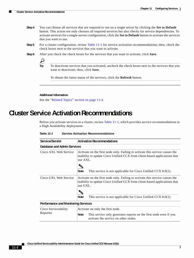
Chapter 11 Configuring Services Cluster Service Activation Recommendations
Step 4 You can choose all services that are required to run on a single server by clicking the Set to Default button. This action not only chooses all required services but also checks for service dependencies. To activate services for a single-server configuration, click the Set to Default button or activate the services that you want to use.
Step 5 For a cluster configuration, review Table 11-1 for service activation recommendations; then, check the check boxes next to the services that you want to activate.
Step 6 After you check the check boxes for the services that you want to activate, click Save.
Tip To deactivate services that you activated, uncheck the check boxes next to the services that you want to deactivate; then, click Save. To obtain the latest status of the services, click the Refresh button.
Additional Information
See the “Related Topics” section on page 11-4.
Cluster Service Activation RecommendationsBefore you activate services in a cluster, review Table 11-1, which provides service recommendations in a High Availability deployment.
Table 11-1 Service Activation Recommendations
Service/Servlet Activation Recommendations
Database and Admin Services
Cisco AXL Web Service Activate on the first node only. Failing to activate this service causes the inability to update Cisco Unified CCX from client-based applications that use AXL.
Note This service is not applicable for Cisco Unified CCX 8.0(1).
Cisco UXL Web Service Activate on the first node only. Failing to activate this service causes the inability to update Cisco Unified CCX from client-based applications that use UXL.
Note This service is not applicable for Cisco Unified CCX 8.0(1).
Performance and Monitoring Services
Cisco Serviceability Reporter
Activate on only the first node.
Note This service only generates reports on the first node even if you activate the service on other nodes.
11-2Cisco Unified Serviceability Administration Guide for Cisco Unifed CCX Release 8.0(1)
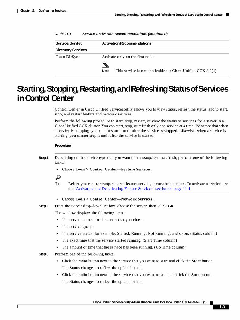
Chapter 11 Configuring Services Starting, Stopping, Restarting, and Refreshing Status of Services in Control Center
Starting, Stopping, Restarting, and Refreshing Status of Services in Control Center
Control Center in Cisco Unified Serviceability allows you to view status, refresh the status, and to start, stop, and restart feature and network services.
Perform the following procedure to start, stop, restart, or view the status of services for a server in a Cisco Unified CCX cluster. You can start, stop, or refresh only one service at a time. Be aware that when a service is stopping, you cannot start it until after the service is stopped. Likewise, when a service is starting, you cannot stop it until after the service is started.
Procedure
Step 1 Depending on the service type that you want to start/stop/restart/refresh, perform one of the following tasks:
• Choose Tools > Control Center—Feature Services.
Tip Before you can start/stop/restart a feature service, it must be activated. To activate a service, see the “Activating and Deactivating Feature Services” section on page 11-1.
• Choose Tools > Control Center—Network Services.
Step 2 From the Server drop-down list box, choose the server; then, click Go.
The window displays the following items:
• The service names for the server that you chose.
• The service group.
• The service status; for example, Started, Running, Not Running, and so on. (Status column)
• The exact time that the service started running. (Start Time column)
• The amount of time that the service has been running. (Up Time column)
Step 3 Perform one of the following tasks:
• Click the radio button next to the service that you want to start and click the Start button.
The Status changes to reflect the updated status.
• Click the radio button next to the service that you want to stop and click the Stop button.
The Status changes to reflect the updated status.
Directory Services
Cisco DirSync Activate only on the first node.
Note This service is not applicable for Cisco Unified CCX 8.0(1).
Table 11-1 Service Activation Recommendations (continued)
Service/Servlet Activation Recommendations
11-3Cisco Unified Serviceability Administration Guide for Cisco Unifed CCX Release 8.0(1)
Chapter 11 Configuring Services Using a Command Line Interface to Start and Stop Services
• Click the radio button next to the service that you want to restart and click the Restart button.
A message indicates that restarting may take a while. Click OK.
• To get the latest status of the services, click the Refresh button.
• To go to the Service Activation window or to the other Control Center window, choose an option from the Related Links drop-down list box and click Go.
Additional Information
See the “Related Topics” section on page 11-4.
Using a Command Line Interface to Start and Stop ServicesYou can start and stop some services through the Command Line Interface (CLI). For a list of services that you can start and stop through the CLI and for information on how to perform these tasks, refer to the Command Line Interface Reference Guide for Cisco Unified Solutions.
Tip You must start and stop most services from Control Center in Cisco Unified Serviceability.
Additional Information
See the “Related Topics” section on page 11-4.
Where to Find More InformationRelated Topics
• Understanding Services, page 9-1
• Activating and Deactivating Feature Services, page 11-1
• Cluster Service Activation Recommendations, page 11-2
• Starting, Stopping, Restarting, and Refreshing Status of Services in Control Center, page 11-3
• Using a Command Line Interface to Start and Stop Services, page 11-4
11-4Cisco Unified Serviceability Administration Guide for Cisco Unifed CCX Release 8.0(1)
Cisco Unified Serviceability Admin
C H A P T E R 12
Configuring Serviceability Reports ArchiveThe Cisco Serviceability Reporter service generates daily reports in Cisco Unified Serviceability. Each report provides a summary that comprises different charts that display the statistics for that particular report. Reporter generates reports once a day on the basis of logged information.
This section describes how to use the Serviceability Reports Archive window.
Before you Begin
Activate the Cisco Serviceability Reporter service, which is CPU intensive. After you activate the service, report generation may take up to 24 hours.
Procedure
Step 1 Choose Tools > Serviceability Reports Archive.
The Serviceability Reports Archive window displays the month and year for which the reports are available.
Step 2 From the Month-Year pane, choose the month and year for which you want to display reports.
A list of days that correspond to the month displays.
Step 3 To view reports, click the link that corresponds to the day for which reports were generated.
The report files for the day that you chose display.
Step 4 To view a particular PDF report, click the link of the report that you want to view.
Tip If you browsed into Cisco Unified Serviceability by using the server name, you must log in to Cisco Unified Serviceability before you can view the report.
Tip If your network uses Network Address Translation (NAT) and you are trying to access serviceability reports inside the NAT, enter the IP address for the private network that is associated with the NAT in the browser URL. If you are trying to access the reports outside the NAT, enter the public IP address, and NAT will accordingly translate/map to the private IP address.
Tip To view PDF reports, you must install Acrobat ® Reader on your machine. To download Acrobat Reader, click the link at the bottom of the Serviceability Reports Archive window.
12-1istration Guide for Cisco Unifed CCX Release 8.0(1)
Chapter 12 Configuring Serviceability Reports Archive Where to Find More Information
A window opens and displays the PDF file of the report that you chose.
Additional Information
See the “Related Topics” section on page 12-2.
Where to Find More InformationRelated Topics
• Understanding Serviceability Reports Archive, page 10-1
Additional Cisco Documentation
Cisco Unified CCX Real-Time Monitoring Tool Administration Guide
12-2Cisco Unified Serviceability Administration Guide for Cisco Unifed CCX Release 8.0(1)
Cisco Unified Serviceability Admin
C H A P T E R 13
Configuring the Audit LogWith audit logging, configuration changes to the Cisco Unified CCX system gets logged in separate log files for auditing. This chapter contains the following topics:
• Understanding Audit Logging, page 13-1
• Configuring the Audit Log, page 13-2
• Audit Log Configuration Settings, page 13-2
• Where to Find More Information, page 13-4
Understanding Audit LoggingWith audit logging, configuration changes to the Cisco Unified CCX system gets logged in separate log files for auditing. The Cisco Audit Event Service, which displays under Control Center—Network Services in Cisco Unified Serviceability, monitors and logs any configuration change to the Cisco Unified CCX system by a user or as a result of the user action.
You access the Audit Log Configuration window in Cisco Unified Serviceability to configure the settings for the audit logs.
Tip Be aware that audit event logging is centralized and enabled by default. An alarm monitor called Syslog Audit writes the logs. By default, the logs are configured to rotate. If the AuditLogAlarmMonitor cannot write an audit event, the AuditLogAlarmMonitor logs this failure as a critical error in the syslog file. The Alert Manager reports this error as part of a SeverityMatchFound alert. The actual operation continues even if the event logging fails. All audit logs get collected, viewed and deleted from Trace and Log Central in the Cisco Unified CCX Real-Time Monitoring Tool.
The following Cisco Unified CCX components generate audit events:
• Cisco Unified Serviceability, page 13-1
• Cisco Unified CCX Real-Time Monitoring Tool, page 13-2
Cisco Unified Serviceability
Cisco Unified Serviceability logs the following events:
• Activation, deactivation, start, or stop of a service.
• Changes in trace configurations and alarm configurations.
• Changes in SNMP configurations.
13-1istration Guide for Cisco Unifed CCX Release 8.0(1)
Chapter 13 Configuring the Audit Log Configuring the Audit Log
• Review of any report in the Serviceability Reports Archive. This log gets viewed on the reporter node.
Cisco Unified CCX Real-Time Monitoring Tool
Cisco Unified CCX Real-Time Monitoring Tool logs the following events with an audit event alarm:
• Alert configuration.
• Alert suspension.
• E-mail configuration.
• Set node alert status.
• Alert addition.
• Add alert action.
• Clear alert.
• Enable alert.
• Remove alert action.
• Remove alert.
Configuring the Audit LogTo configure the audit log, perform the following procedure:
Procedure
Step 1 In Cisco Unified Serviceability, choose Tools > Audit Log Configuration.
The Audit Log Configuration window displays.
Step 2 Configure the settings in Table 13-1.
Step 3 Click Save.
Tip At any time, you can click Set to Default to specify the default values. After you set the defaults, click Save to save the default values.
Additional Information
See the “Related Topics” section on page 13-4.
Audit Log Configuration SettingsTable 13-1 describes the settings that you can configure in the Audit Log Configuration window in Cisco Unified Serviceability. For more information on audit logging, see the “Where to Find More Information” section on page 13-4.
13-2Cisco Unified Serviceability Administration Guide for Cisco Unifed CCX Release 8.0(1)
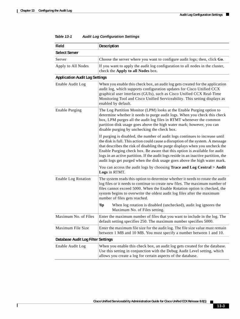
Chapter 13 Configuring the Audit Log Audit Log Configuration Settings
Table 13-1 Audit Log Configuration Settings
Field Description
Select Server
Server Choose the server where you want to configure audit logs; then, click Go.
Apply to All Nodes If you want to apply the audit log configuration to all nodes in the cluster, check the Apply to all Nodes box.
Application Audit Log Settings
Enable Audit Log When you enable this check box, an audit log gets created for the application audit log, which supports configuration updates for Cisco Unified CCX graphical user interfaces (GUIs), such as Cisco Unified CCX Real-Time Monitoring Tool and Cisco Unified Serviceability. This setting displays as enabled by default.
Enable Purging The Log Partition Monitor (LPM) looks at the Enable Purging option to determine whether it needs to purge audit logs. When you check this check box, LPM purges all the audit log files in RTMT whenever the common partition disk usage goes above the high water mark; however, you can disable purging by unchecking the check box.
If purging is disabled, the number of audit logs continues to increase until the disk is full. This action could cause a disruption of the system. A message that describes the risk of disabling the purge displays when you uncheck the Enable Purging check box. Be aware that this option is available for audit logs in an active partition. If the audit logs reside in an inactive partition, the audit logs get purged when the disk usage goes above the high water mark.
You can access the audit logs by choosing Trace and Log Central > Audit Logs in RTMT.
Enable Log Rotation The system reads this option to determine whether it needs to rotate the audit log files or it needs to continue to create new files. The maximum number of files cannot exceed 5000. When the Enable Rotation option is checked, the system begins to overwrite the oldest audit log files after the maximum number of files gets reached.
Tip When log rotation is disabled (unchecked), audit log ignores the Maximum No. of Files setting.
Maximum No. of Files Enter the maximum number of files that you want to include in the log. The default setting specifies 250. The maximum number specifies 5000.
Maximum File Size Enter the maximum file size for the audit log. The file size value must remain between 1 MB and 10 MB. You must specify a number between 1 and 10.
Database Audit Log Filter Settings
Enable Audit Log When you enable this check box, an audit log gets created for the database. Use this setting in conjunction with the Debug Audit Level setting, which allows you create a log for certain aspects of the database.
13-3Cisco Unified Serviceability Administration Guide for Cisco Unifed CCX Release 8.0(1)
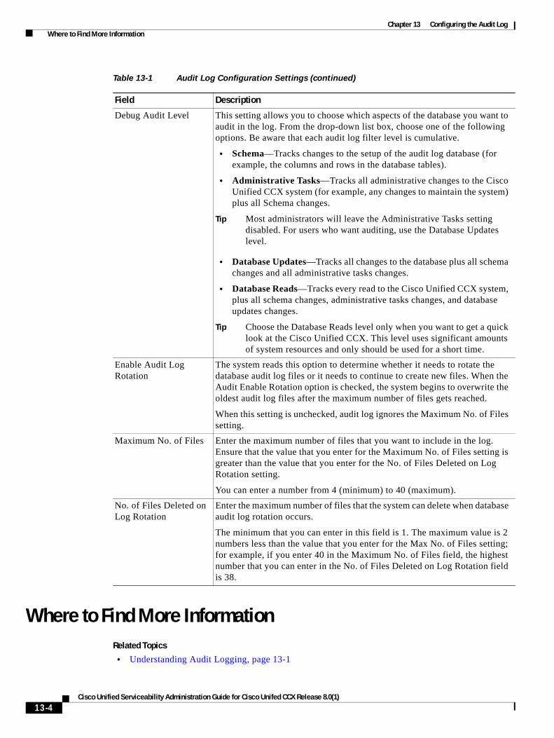
Chapter 13 Configuring the Audit Log Where to Find More Information
Where to Find More InformationRelated Topics
• Understanding Audit Logging, page 13-1
Debug Audit Level This setting allows you to choose which aspects of the database you want to audit in the log. From the drop-down list box, choose one of the following options. Be aware that each audit log filter level is cumulative.
• Schema—Tracks changes to the setup of the audit log database (for example, the columns and rows in the database tables).
• Administrative Tasks—Tracks all administrative changes to the Cisco Unified CCX system (for example, any changes to maintain the system) plus all Schema changes.
Tip Most administrators will leave the Administrative Tasks setting disabled. For users who want auditing, use the Database Updates level.
• Database Updates—Tracks all changes to the database plus all schema changes and all administrative tasks changes.
• Database Reads—Tracks every read to the Cisco Unified CCX system, plus all schema changes, administrative tasks changes, and database updates changes.
Tip Choose the Database Reads level only when you want to get a quick look at the Cisco Unified CCX. This level uses significant amounts of system resources and only should be used for a short time.
Enable Audit Log Rotation
The system reads this option to determine whether it needs to rotate the database audit log files or it needs to continue to create new files. When the Audit Enable Rotation option is checked, the system begins to overwrite the oldest audit log files after the maximum number of files gets reached.
When this setting is unchecked, audit log ignores the Maximum No. of Files setting.
Maximum No. of Files Enter the maximum number of files that you want to include in the log. Ensure that the value that you enter for the Maximum No. of Files setting is greater than the value that you enter for the No. of Files Deleted on Log Rotation setting.
You can enter a number from 4 (minimum) to 40 (maximum).
No. of Files Deleted on Log Rotation
Enter the maximum number of files that the system can delete when database audit log rotation occurs.
The minimum that you can enter in this field is 1. The maximum value is 2 numbers less than the value that you enter for the Max No. of Files setting; for example, if you enter 40 in the Maximum No. of Files field, the highest number that you can enter in the No. of Files Deleted on Log Rotation field is 38.
Table 13-1 Audit Log Configuration Settings (continued)
Field Description
13-4Cisco Unified Serviceability Administration Guide for Cisco Unifed CCX Release 8.0(1)
Chapter 13 Configuring the Audit Log Where to Find More Information
• Configuring the Audit Log, page 13-2
• Audit Log Configuration Settings, page 13-2
• Configuring Trace, page 7-1
• Configuring Troubleshooting Trace Settings, page 8-1
• Network Services, page 9-2
Additional Cisco Documentation
• Cisco Unified CCX Real-Time Monitoring Tool Administration Guide
• Cisco Unified CCX Administration Guide
13-5Cisco Unified Serviceability Administration Guide for Cisco Unifed CCX Release 8.0(1)

Chapter 13 Configuring the Audit Log Where to Find More Information
13-6Cisco Unified Serviceability Administration Guide for Cisco Unifed CCX Release 8.0(1)
P A R T 5
Simple Network Management Protocol (SNMP)

Cisco Unified Serviceability Admin
C H A P T E R 14
Understanding Simple Network Management ProtocolThis chapter provides information on the following topics:
• Simple Network Management Protocol Support, page 14-1
• SNMP Basics, page 14-1
• SNMP Master Agent and Subagents, page 14-2
• SNMP Configuration Requirements, page 14-2
• SNMP Version 1 Support, page 14-2
• SNMP Version 2c Support, page 14-3
• SNMP Version 3 Support, page 14-3
• SNMP Services, page 14-3
• SNMP Community Strings and Users, page 14-4
• SNMP Traps and Informs, page 14-4
• SNMP Management Information Base (MIB), page 14-5
• SNMP Trace Configuration, page 14-9
• SNMP Configuration Checklist, page 14-9
Simple Network Management Protocol SupportSimple Network Management Protocol (SNMP) is an industry-standard interface for exchanging management information between network devices. SNMP and its components provide you with information about your Cisco Unified CCX system. You can refer to this information to monitor and manage the status of the Cisco Unified CCX system, its subsystems, and its related installed components. You can also use this information to troubleshoot problems, if they arise.
You can set up SNMP traps to automatically notify you of high-severity messages and errors that are generated by the Cisco Unified CCX system.
SNMP BasicsA network management system (NMS) uses SNMP to exchange management information between devices on a network. An SNMP-managed network is made up of the following main components:
14-1istration Guide for Cisco Unifed CCX Release 8.0(1)
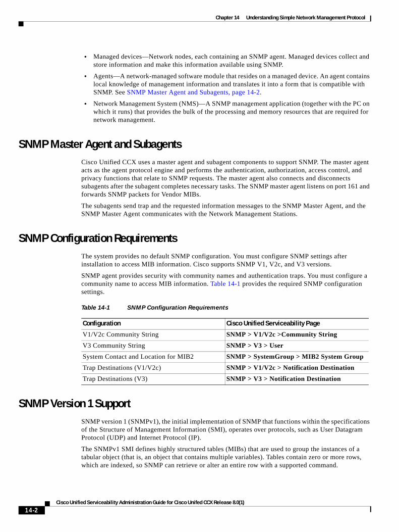
Chapter 14 Understanding Simple Network Management Protocol
• Managed devices—Network nodes, each containing an SNMP agent. Managed devices collect and store information and make this information available using SNMP.
• Agents—A network-managed software module that resides on a managed device. An agent contains local knowledge of management information and translates it into a form that is compatible with SNMP. See SNMP Master Agent and Subagents, page 14-2.
• Network Management System (NMS)—A SNMP management application (together with the PC on which it runs) that provides the bulk of the processing and memory resources that are required for network management.
SNMP Master Agent and SubagentsCisco Unified CCX uses a master agent and subagent components to support SNMP. The master agent acts as the agent protocol engine and performs the authentication, authorization, access control, and privacy functions that relate to SNMP requests. The master agent also connects and disconnects subagents after the subagent completes necessary tasks. The SNMP master agent listens on port 161 and forwards SNMP packets for Vendor MIBs.
The subagents send trap and the requested information messages to the SNMP Master Agent, and the SNMP Master Agent communicates with the Network Management Stations.
SNMP Configuration RequirementsThe system provides no default SNMP configuration. You must configure SNMP settings after installation to access MIB information. Cisco supports SNMP V1, V2c, and V3 versions.
SNMP agent provides security with community names and authentication traps. You must configure a community name to access MIB information. Table 14-1 provides the required SNMP configuration settings.
SNMP Version 1 SupportSNMP version 1 (SNMPv1), the initial implementation of SNMP that functions within the specifications of the Structure of Management Information (SMI), operates over protocols, such as User Datagram Protocol (UDP) and Internet Protocol (IP).
The SNMPv1 SMI defines highly structured tables (MIBs) that are used to group the instances of a tabular object (that is, an object that contains multiple variables). Tables contain zero or more rows, which are indexed, so SNMP can retrieve or alter an entire row with a supported command.
Table 14-1 SNMP Configuration Requirements
Configuration Cisco Unified Serviceability Page
V1/V2c Community String SNMP > V1/V2c >Community String
V3 Community String SNMP > V3 > User
System Contact and Location for MIB2 SNMP > SystemGroup > MIB2 System Group
Trap Destinations (V1/V2c) SNMP > V1/V2c > Notification Destination
Trap Destinations (V3) SNMP > V3 > Notification Destination
14-2Cisco Unified Serviceability Administration Guide for Cisco Unifed CCX Release 8.0(1)
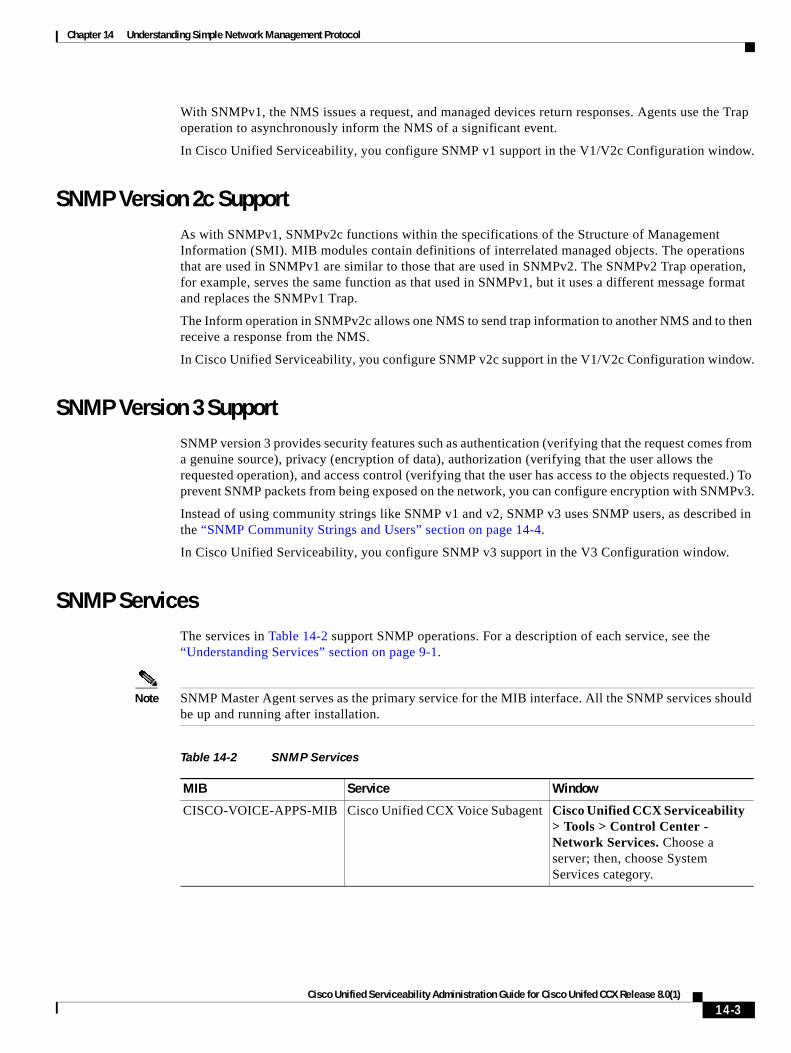
Chapter 14 Understanding Simple Network Management Protocol
With SNMPv1, the NMS issues a request, and managed devices return responses. Agents use the Trap operation to asynchronously inform the NMS of a significant event.
In Cisco Unified Serviceability, you configure SNMP v1 support in the V1/V2c Configuration window.
SNMP Version 2c SupportAs with SNMPv1, SNMPv2c functions within the specifications of the Structure of Management Information (SMI). MIB modules contain definitions of interrelated managed objects. The operations that are used in SNMPv1 are similar to those that are used in SNMPv2. The SNMPv2 Trap operation, for example, serves the same function as that used in SNMPv1, but it uses a different message format and replaces the SNMPv1 Trap.
The Inform operation in SNMPv2c allows one NMS to send trap information to another NMS and to then receive a response from the NMS.
In Cisco Unified Serviceability, you configure SNMP v2c support in the V1/V2c Configuration window.
SNMP Version 3 SupportSNMP version 3 provides security features such as authentication (verifying that the request comes from a genuine source), privacy (encryption of data), authorization (verifying that the user allows the requested operation), and access control (verifying that the user has access to the objects requested.) To prevent SNMP packets from being exposed on the network, you can configure encryption with SNMPv3.
Instead of using community strings like SNMP v1 and v2, SNMP v3 uses SNMP users, as described in the “SNMP Community Strings and Users” section on page 14-4.
In Cisco Unified Serviceability, you configure SNMP v3 support in the V3 Configuration window.
SNMP ServicesThe services in Table 14-2 support SNMP operations. For a description of each service, see the “Understanding Services” section on page 9-1.
Note SNMP Master Agent serves as the primary service for the MIB interface. All the SNMP services should be up and running after installation.
Table 14-2 SNMP Services
MIB Service Window
CISCO-VOICE-APPS-MIB Cisco Unified CCX Voice Subagent Cisco Unified CCX Serviceability > Tools > Control Center - Network Services. Choose a server; then, choose System Services category.
14-3Cisco Unified Serviceability Administration Guide for Cisco Unifed CCX Release 8.0(1)
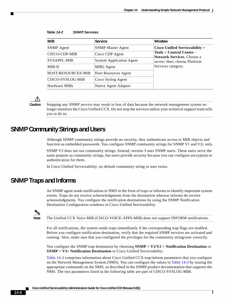
Chapter 14 Understanding Simple Network Management Protocol
Caution Stopping any SNMP service may result in loss of data because the network management system no longer monitors the Cisco Unified CCX. Do not stop the services unless your technical support team tells you to do so.
SNMP Community Strings and UsersAlthough SNMP community strings provide no security, they authenticate access to MIB objects and function as embedded passwords. You configure SNMP community strings for SNMP V1 and V2c only.
SNMP V3 does not use community strings. Instead, version 3 uses SNMP users. These users serve the same purpose as community strings, but users provide security because you can configure encryption or authentication for them.
In Cisco Unified Serviceability, no default community string or user exists.
SNMP Traps and InformsAn SNMP agent sends notifications to NMS in the form of traps or informs to identify important system events. Traps do not receive acknowledgments from the destination whereas informs do receive acknowledgments. You configure the notification destinations by using the SNMP Notification Destination Configuration windows in Cisco Unified Serviceability.
Note The Unified CCX Voice MIB (CISCO-VOICE-APPS-MIB) does not support INFORM notifications.
For all notifications, the system sends traps immediately if the corresponding trap flags are enabled. Before you configure notification destination, verify that the required SNMP services are activated and running. Also, make sure that you configured the privileges for the community string/user correctly. You configure the SNMP trap destination by choosing SNMP > V1/V2 > Notification Destination or SNMP > V3> Notification Destination in Cisco Unified Serviceability.
Table 14-3 comprises information about Cisco Unified CCX trap/inform parameters that you configure on the Network Management System (NMS). You can configure the values in Table 14-3 by issuing the appropriate commands on the NMS, as described in the SNMP product documentation that supports the NMS. The two parameters listed in the following table are part of CISCO-SYSLOG-MIB.
SNMP Agent SNMP Master Agent Cisco Unified Serviceability > Tools > Control Center - Network Services. Choose a server; then, choose Platform Services category.
CISCO-CDP-MIB Cisco CDP Agent
SYSAPPL-MIB System Application Agent
MIB-II MIB2 Agent
HOST-RESOURCES-MIB Host Resources Agent
CISCO-SYSLOG-MIB Cisco Syslog Agent
Hardware MIBs Native Agent Adaptor
Table 14-2 SNMP Services
MIB Service Window
14-4Cisco Unified Serviceability Administration Guide for Cisco Unifed CCX Release 8.0(1)
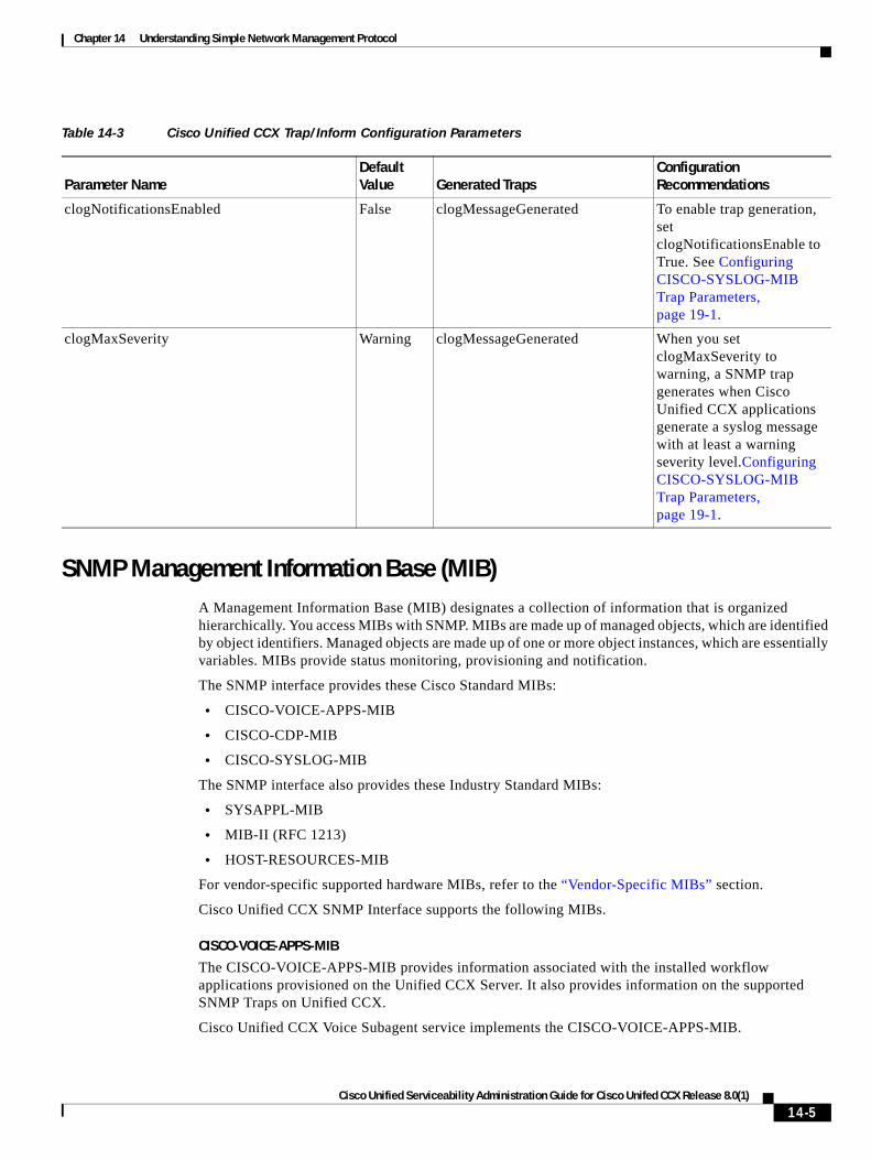
Chapter 14 Understanding Simple Network Management Protocol
SNMP Management Information Base (MIB)A Management Information Base (MIB) designates a collection of information that is organized hierarchically. You access MIBs with SNMP. MIBs are made up of managed objects, which are identified by object identifiers. Managed objects are made up of one or more object instances, which are essentially variables. MIBs provide status monitoring, provisioning and notification.
The SNMP interface provides these Cisco Standard MIBs:
• CISCO-VOICE-APPS-MIB
• CISCO-CDP-MIB
• CISCO-SYSLOG-MIB
The SNMP interface also provides these Industry Standard MIBs:
• SYSAPPL-MIB
• MIB-II (RFC 1213)
• HOST-RESOURCES-MIB
For vendor-specific supported hardware MIBs, refer to the “Vendor-Specific MIBs” section.
Cisco Unified CCX SNMP Interface supports the following MIBs.
CISCO-VOICE-APPS-MIB
The CISCO-VOICE-APPS-MIB provides information associated with the installed workflow applications provisioned on the Unified CCX Server. It also provides information on the supported SNMP Traps on Unified CCX.
Cisco Unified CCX Voice Subagent service implements the CISCO-VOICE-APPS-MIB.
Table 14-3 Cisco Unified CCX Trap/Inform Configuration Parameters
Parameter NameDefault Value Generated Traps
Configuration Recommendations
clogNotificationsEnabled False clogMessageGenerated To enable trap generation, set clogNotificationsEnable to True. See Configuring CISCO-SYSLOG-MIB Trap Parameters, page 19-1.
clogMaxSeverity Warning clogMessageGenerated When you set clogMaxSeverity to warning, a SNMP trap generates when Cisco Unified CCX applications generate a syslog message with at least a warning severity level.Configuring CISCO-SYSLOG-MIB Trap Parameters, page 19-1.
14-5Cisco Unified Serviceability Administration Guide for Cisco Unifed CCX Release 8.0(1)
Chapter 14 Understanding Simple Network Management Protocol
For more information about the CISCO-VOICE-APPS-MIB, refer to this URL: ftp://ftp.cisco.com/pub/mibs/v2/CISCO-VOICE-APPS-MIB.my.
Cisco Unified CCX Voice Subagent Service communicates with the SNMP Master Agent through Cisco Unified CCX SNMP Java Adaptor. The Cisco Unified CCX SNMP Java Adaptor service should be up and running for the Unified CCX Voice Subagent to work properly.
You can manage Cisco Unified CCX SNMP Java Adaptor service from Cisco Unified CCX Serviceability web interface.
Note In Cisco Unified CCX 8.0(1), while exposing the Unified CCX workflow information through CISCO-VOICE-APPS-MIB, only one trigger per application row will be returned when doing a walk on the workflow table (cvaWorkflowInstallTable object). If there are multiple triggers associated with a Workflow application, these will be shown as separate entries (rows).
CISCO-CDP-MIB
The CISCO-CDP-MIB provides information about device identifications, CDP running status, CDP transmitting frequency, and the time for the receiving device to hold CDP messages (time to live). This MIB stores information in a table called cdpGlobalInfo.
The CDP subagent implements the CDP-MIB.
For more information about the CISCO-CDP-MIB, refer to this URL: ftp://ftp.cisco.com/pub/mibs/v2/CISCO-CDP-MIB.my
SYSAPPL-MIB
Use the System Application Agent to get information from the SYSAPPL-MIB, such as installed applications, application components, and processes that are running on the system.
Note Unlike previous releases of Cisco Unified CCX, the SysAppl MIB implementation in Unified CCX 8.0(1) does not distinguish between Unified CCX activated services and deactivated services. It shows all the installed services in Unified CCX.
Note In Unified CCX 8.0(1), the SysAppl MIB will not provide the Unified CCX subsystem information and their status information. You can view the subsystem and their status information through Cisco Unified CCX Serviceability web interface.
The SYSAPPL-MIB allows you to use CiscoWorks or a third-party NMS browser to remotely access information about the Cisco Unified CCX components including:
• Cisco Unified CCX Engine
• Cisco Unified CCX Database
• Cisco Desktop License and Resource Manager Service
• Cisco Desktop Call/Chat Service
• Cisco Desktop Enterprise Service
• Cisco Desktop Sync Service
• Cisco Desktop Browser and IP Phone Agent Service
• Cisco Desktop Recording and Statistics Service
14-6Cisco Unified Serviceability Administration Guide for Cisco Unifed CCX Release 8.0(1)
Chapter 14 Understanding Simple Network Management Protocol
• Cisco Desktop VoIP Monitor Service
• Cisco Desktop Recording and Playback Service
• Cisco Desktop LDAP Monitor Service
• Cisco Desktop Agent E-Mail Service
• Cisco Unified CCX Voice Subagent
• Cisco Unified CCX Cluster View Daemon
• Cisco Unified CCX SNMP Java Adapter
• Cisco Unified CCX DB Perfmon Counter Service
• Cisco Unified CCX Perfmon Counter Service
MIB-II
Use MIB2 agent to get information from MIB-II. The MIB2 agent provides access to variables that are defined in RFC 1213, such as interfaces, IP, and so on, and supports the following groups of objects:
• system
• interfaces
• at
• ip
• icmp
• tcp
• udp
• snmp
HOST-RESOURCES MIB
Use Host Resources Agent to get values from HOST-RESOURCES-MIB. The Host Resources Agent provides SNMP access to host information, such as storage resources, process tables, device information, and installed software base. The Host Resources Agent supports the following groups of objects:
• hrSystem
• hrStorage
• hrDevice
• hrSWRun
• hrSWRunPerf
• hrSWInstalled
CISCO-SYSLOG-MIB
Syslog tracks and logs all system messages, from informational through critical. With this MIB, network management applications can receive syslog messages as SNMP traps:
The Cisco Syslog Agent supports trap functionality with the following MIB objects:
• clogNotificationsSent
• clogNotificationsEnabled
• clogMaxSeverity
14-7Cisco Unified Serviceability Administration Guide for Cisco Unifed CCX Release 8.0(1)
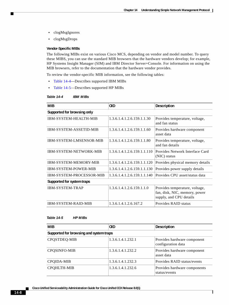
Chapter 14 Understanding Simple Network Management Protocol
• clogMsgIgnores
• clogMsgDrops
Vendor-Specific MIBs
The following MIBs exist on various Cisco MCS, depending on vendor and model number. To query these MIBS, you can use the standard MIB browsers that the hardware vendors develop; for example, HP Systems Insight Manager (SIM) and IBM Director Server+Console. For information on using the MIB browsers, refer to the documentation that the hardware vendor provides.
To review the vendor-specific MIB information, see the following tables:
• Table 14-4—Describes supported IBM MIBs
• Table 14-5—Describes supported HP MIBs
Table 14-4 IBM MIBs
MIB OID Description
Supported for browsing only
IBM-SYSTEM-HEALTH-MIB 1.3.6.1.4.1.2.6.159.1.1.30 Provides temperature, voltage, and fan status
IBM-SYSTEM-ASSETID-MIB 1.3.6.1.4.1.2.6.159.1.1.60 Provides hardware component asset data
IBM-SYSTEM-LMSENSOR-MIB 1.3.6.1.4.1.2.6.159.1.1.80 Provides temperature, voltage, and fan details
IBM-SYSTEM-NETWORK-MIB 1.3.6.1.4.1.2.6.159.1.1.110 Provides Network Interface Card (NIC) status
IBM-SYSTEM-MEMORY-MIB 1.3.6.1.4.1.2.6.159.1.1.120 Provides physical memory details
IBM-SYSTEM-POWER-MIB 1.3.6.1.4.1.2.6.159.1.1.130 Provides power supply details
IBM-SYSTEM-PROCESSOR-MIB 1.3.6.1.4.1.2.6.159.1.1.140 Provides CPU asset/status data
Supported for system traps
IBM-SYSTEM-TRAP 1.3.6.1.4.1.2.6.159.1.1.0 Provides temperature, voltage, fan, disk, NIC, memory, power supply, and CPU details
IBM-SYSTEM-RAID-MIB 1.3.6.1.4.1.2.6.167.2 Provides RAID status
Table 14-5 HP MIBs
MIB OID Description
Supported for browsing and system traps
CPQSTDEQ-MIB 1.3.6.1.4.1.232.1 Provides hardware component configuration data
CPQSINFO-MIB 1.3.6.1.4.1.232.2 Provides hardware component asset data
CPQIDA-MIB 1.3.6.1.4.1.232.3 Provides RAID status/events
CPQHLTH-MIB 1.3.6.1.4.1.232.6 Provides hardware components status/events
14-8Cisco Unified Serviceability Administration Guide for Cisco Unifed CCX Release 8.0(1)
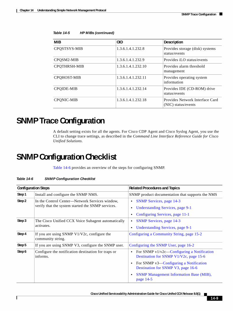
Chapter 14 Understanding Simple Network Management Protocol SNMP Trace Configuration
SNMP Trace ConfigurationA default setting exists for all the agents. For Cisco CDP Agent and Cisco Syslog Agent, you use the CLI to change trace settings, as described in the Command Line Interface Reference Guide for Cisco Unified Solutions.
SNMP Configuration ChecklistTable 14-6 provides an overview of the steps for configuring SNMP.
CPQSTSYS-MIB 1.3.6.1.4.1.232.8 Provides storage (disk) systems status/events
CPQSM2-MIB 1.3.6.1.4.1.232.9 Provides iLO status/events
CPQTHRSH-MIB 1.3.6.1.4.1.232.10 Provides alarm threshold management
CPQHOST-MIB 1.3.6.1.4.1.232.11 Provides operating system information
CPQIDE-MIB 1.3.6.1.4.1.232.14 Provides IDE (CD-ROM) drive status/events
CPQNIC-MIB 1.3.6.1.4.1.232.18 Provides Network Interface Card (NIC) status/events
Table 14-5 HP MIBs (continued)
MIB OID Description
Table 14-6 SNMP Configuration Checklist
Configuration Steps Related Procedures and Topics
Step 1 Install and configure the SNMP NMS. SNMP product documentation that supports the NMS
Step 2 In the Control Center—Network Services window, verify that the system started the SNMP services.
• SNMP Services, page 14-3
• Understanding Services, page 9-1
• Configuring Services, page 11-1
Step 3 The Cisco Unified CCX Voice Subagent automatically activates.
• SNMP Services, page 14-3
• Understanding Services, page 9-1
Step 4 If you are using SNMP V1/V2c, configure the community string.
Configuring a Community String, page 15-2
Step 5 If you are using SNMP V3, configure the SNMP user. Configuring the SNMP User, page 16-2
Step 6 Configure the notification destination for traps or informs.
• For SNMP v1/v2c—Configuring a Notification Destination for SNMP V1/V2c, page 15-6
• For SNMP v3—Configuring a Notification Destination for SNMP V3, page 16-6
• SNMP Management Information Base (MIB), page 14-5
14-9Cisco Unified Serviceability Administration Guide for Cisco Unifed CCX Release 8.0(1)
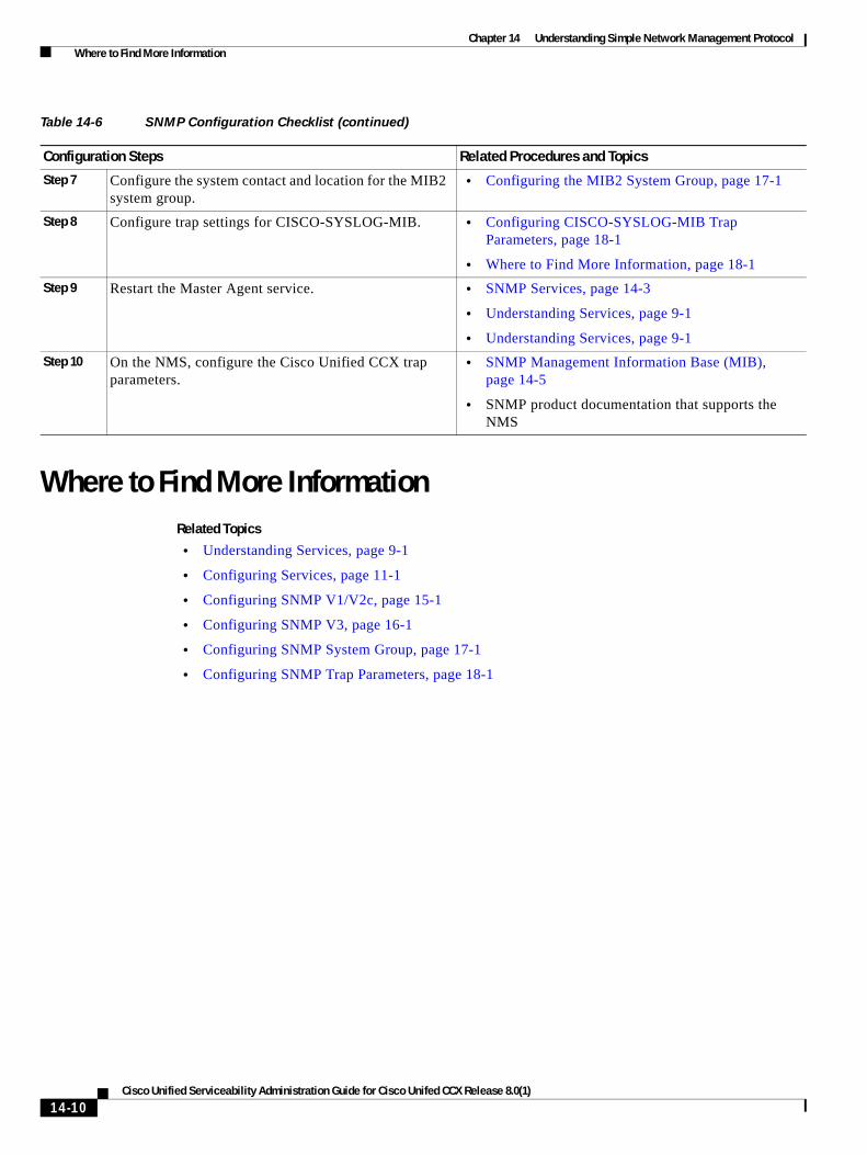
Chapter 14 Understanding Simple Network Management Protocol Where to Find More Information
Where to Find More InformationRelated Topics
• Understanding Services, page 9-1
• Configuring Services, page 11-1
• Configuring SNMP V1/V2c, page 15-1
• Configuring SNMP V3, page 16-1
• Configuring SNMP System Group, page 17-1
• Configuring SNMP Trap Parameters, page 18-1
Step 7 Configure the system contact and location for the MIB2 system group.
• Configuring the MIB2 System Group, page 17-1
Step 8 Configure trap settings for CISCO-SYSLOG-MIB. • Configuring CISCO-SYSLOG-MIB Trap Parameters, page 18-1
• Where to Find More Information, page 18-1
Step 9 Restart the Master Agent service. • SNMP Services, page 14-3
• Understanding Services, page 9-1
• Understanding Services, page 9-1
Step 10 On the NMS, configure the Cisco Unified CCX trap parameters.
• SNMP Management Information Base (MIB), page 14-5
• SNMP product documentation that supports the NMS
Table 14-6 SNMP Configuration Checklist (continued)
Configuration Steps Related Procedures and Topics
14-10Cisco Unified Serviceability Administration Guide for Cisco Unifed CCX Release 8.0(1)
Cisco Unified Serviceability Admin
C H A P T E R 15
Configuring SNMP V1/V2cThis chapter describes how to configure SNMP versions 1 and 2c, so that the network management system can monitor both Unified CCX and Unified Communications platform and it contains the following topics:
• Finding a Community String, page 15-1
• Configuring a Community String, page 15-2
• Community String Configuration Settings, page 15-3
• Deleting a Community String, page 15-4
• SNMP Notification Destination, page 15-5
• Finding a Notification Destination for SNMP V1/V2c, page 15-5
• Configuring a Notification Destination for SNMP V1/V2c, page 15-6
• Notification Destination Configuration Settings for SNMP V1/V2c, page 15-7
• Deleting a Notification Destination for SNMP V1/V2c, page 15-8
• Where to Find More Information, page 15-8
Tip If you use SNMP version 3, see the “Configuring SNMP V3” section on page 16-1.
Finding a Community String
Tip The Add New button does not display in the SNMP Community String Configuration window until you click the Find button. If no community strings exist and you want to add a community string, click the Find button and wait for the window to refresh. The Add New button displays.
To find a community string, perform the following procedure:
Procedure
Step 1 Choose Snmp > V1/V2c > Community String.
The Find/List window displays.
15-1istration Guide for Cisco Unifed CCX Release 8.0(1)
Chapter 15 Configuring SNMP V1/V2c Configuring a Community String
Step 2 From the Find Community Strings where Name drop-down list box, choose the specific search criteria that you want to use for the community string.
Step 3 Enter the community string for which you want to search.
Step 4 In the Server field, enter the hostname or IP address of the server where the community string exists.
Step 5 Click Find.
After you click the Find button, the Add New button displays. After the search results display, the Apply to All Nodes check box displays.
Step 6 If you want to apply the configuration from one of the options in the search results to all nodes in the cluster, check the check box next to the name of the option and check the Apply to All Nodes check box.
Step 7 From the list of results, click the community string that you want to view.
Step 8 To add or update a community string, see the “Configuring a Community String” section on page 15-2.
Additional Information
See the “Where to Find More Information” section on page 15-8.
Configuring a Community StringBecause the SNMP agent provides security by using community strings, you must configure the community string to access any management information base (MIB) in a Cisco Unified CCX system. Change the community string to limit access to the Cisco Unified CCX system. To add, modify, and delete community strings, access the SNMP Community String configuration window.
Procedure
Step 1 Perform the procedure in the “Finding a Community String” section on page 15-1.
Step 2 Perform one of the following tasks:
• To add a new community string, click the Add New button and go to Step 3.
• To modify an existing community string, locate the community string, as described in the “Finding a Community String” section on page 15-1; click the name of the community string that you want to edit and go to Step 3.
You cannot change the name of the community string or the server.
• To delete a community string, see the “Deleting a Community String” section on page 15-4.
Step 3 Enter the configuration settings, as described in Table 15-1.
Tip Before you save the configuration, you can click the Clear All button at any time to delete all information that you entered for all settings in the window.
Step 4 After you complete the configuration, click Add New to save a new community string or click Save to save changes to an existing community string.
Step 5 A message indicates that changes will not take effect until you restart the SNMP master agent. To continue the configuration without restarting the SNMP master agent, click Cancel. To restart the SNMP master agent service, click OK.
15-2Cisco Unified Serviceability Administration Guide for Cisco Unifed CCX Release 8.0(1)
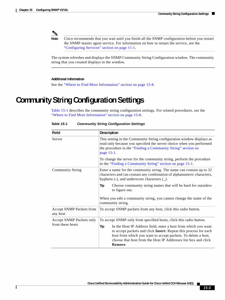
Chapter 15 Configuring SNMP V1/V2c Community String Configuration Settings
Note Cisco recommends that you wait until you finish all the SNMP configuration before you restart the SNMP master agent service. For information on how to restart the service, see the “Configuring Services” section on page 11-1.
The system refreshes and displays the SNMP Community String Configuration window. The community string that you created displays in the window.
Additional Information
See the “Where to Find More Information” section on page 15-8.
Community String Configuration SettingsTable 15-1 describes the community string configuration settings. For related procedures, see the “Where to Find More Information” section on page 15-8.
Table 15-1 Community String Configuration Settings
Field Description
Server This setting in the Community String configuration window displays as read only because you specified the server choice when you performed the procedure in the “Finding a Community String” section on page 15-1.
To change the server for the community string, perform the procedure in the “Finding a Community String” section on page 15-1.
Community String Enter a name for the community string. The name can contain up to 32 characters and can contain any combination of alphanumeric characters, hyphens (-), and underscore characters (_).
Tip Choose community string names that will be hard for outsiders to figure out.
When you edit a community string, you cannot change the name of the community string.
Accept SNMP Packets from any host
To accept SNMP packets from any host, click this radio button.
Accept SNMP Packets only from these hosts
To accept SNMP only from specified hosts, click this radio button.
Tip In the Host IP Address field, enter a host from which you want to accept packets and click Insert. Repeat this process for each host from which you want to accept packets. To delete a host, choose that host from the Host IP Addresses list box and click Remove.
15-3Cisco Unified Serviceability Administration Guide for Cisco Unifed CCX Release 8.0(1)
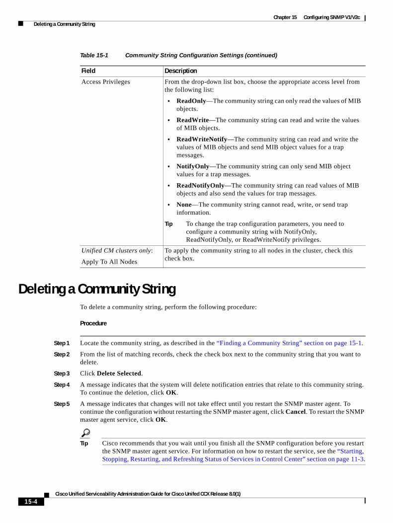
Chapter 15 Configuring SNMP V1/V2c Deleting a Community String
Deleting a Community StringTo delete a community string, perform the following procedure:
Procedure
Step 1 Locate the community string, as described in the “Finding a Community String” section on page 15-1.
Step 2 From the list of matching records, check the check box next to the community string that you want to delete.
Step 3 Click Delete Selected.
Step 4 A message indicates that the system will delete notification entries that relate to this community string. To continue the deletion, click OK.
Step 5 A message indicates that changes will not take effect until you restart the SNMP master agent. To continue the configuration without restarting the SNMP master agent, click Cancel. To restart the SNMP master agent service, click OK.
Tip Cisco recommends that you wait until you finish all the SNMP configuration before you restart the SNMP master agent service. For information on how to restart the service, see the “Starting, Stopping, Restarting, and Refreshing Status of Services in Control Center” section on page 11-3.
Access Privileges From the drop-down list box, choose the appropriate access level from the following list:
• ReadOnly—The community string can only read the values of MIB objects.
• ReadWrite—The community string can read and write the values of MIB objects.
• ReadWriteNotify—The community string can read and write the values of MIB objects and send MIB object values for a trap messages.
• NotifyOnly—The community string can only send MIB object values for a trap messages.
• ReadNotifyOnly—The community string can read values of MIB objects and also send the values for trap messages.
• None—The community string cannot read, write, or send trap information.
Tip To change the trap configuration parameters, you need to configure a community string with NotifyOnly, ReadNotifyOnly, or ReadWriteNotify privileges.
Unified CM clusters only:
Apply To All Nodes
To apply the community string to all nodes in the cluster, check this check box.
Table 15-1 Community String Configuration Settings (continued)
Field Description
15-4Cisco Unified Serviceability Administration Guide for Cisco Unifed CCX Release 8.0(1)
Chapter 15 Configuring SNMP V1/V2c SNMP Notification Destination
After the window refreshes, the string that you deleted no longer displays in the results.
Additional Information
See the “Where to Find More Information” section on page 15-8.
SNMP Notification DestinationThe following sections apply to SNMP V1/V2c notification destination configuration.
• Finding a Notification Destination for SNMP V1/V2c, page 15-5
• Configuring a Notification Destination for SNMP V1/V2c, page 15-6
• Notification Destination Configuration Settings for SNMP V1/V2c, page 15-7
• Deleting a Notification Destination for SNMP V1/V2c, page 15-8
Finding a Notification Destination for SNMP V1/V2c
Tip The Add New button does not display in the SNMP Notification Destination Configuration window until you click the Find button. If no notification destinations exist and you want to add a notification destination, click the Find button and wait for the window to refresh. The Add New button displays.
To find a notification destination for V1/V2c, perform the following procedure:
Procedure
Step 1 Choose Snmp > V1/V2c > Notification Destination.
The Find/List window displays.
Step 2 From the Find Notification where Destination IP drop-down list box, choose the specific search criteria that you want to use to find the notification destination.
Step 3 Enter the notification destination for which you want to search.
Step 4 In the Server field, enter the hostname or IP address of the server that supports the notification destination.
Step 5 Click Find.
After you click the Find button, the Add New button displays. After the search results display, the Apply to All Nodes check box displays.
Step 6 If you want to apply the configuration from one of the options in the search results to all nodes in the cluster, check the check box next to the name of the option and check the Apply to All Nodes check box.
Step 7 To view the configuration for one of the items in the search results, click the item.
Step 8 To add or update a notification string, see the “Configuring a Notification Destination for SNMP V1/V2c” section on page 15-6.
15-5Cisco Unified Serviceability Administration Guide for Cisco Unifed CCX Release 8.0(1)
Chapter 15 Configuring SNMP V1/V2c Configuring a Notification Destination for SNMP V1/V2c
Additional Information
See the “Where to Find More Information” section on page 15-8.
Configuring a Notification Destination for SNMP V1/V2cTo configure the notification destination (trap receiver) for V1/V2c, perform the following procedure.
Procedure
Step 1 Perform the procedure in the “Finding a Notification Destination for SNMP V1/V2c” section on page 15-5.
Step 2 Perform one of the following tasks:
• To add a new SNMP notification destination, click the Add New button and go to Step 3.
You configure the notification destination for the server that you choose in the Server drop-down list box in the Find/List window.
• To modify an existing SNMP notification destination, locate the notification destination, as described in the “Finding a Notification Destination for SNMP V1/V2c” section on page 15-5; click the name of the SNMP notification destination that you want to edit and go to Step 3.
• To delete an SNMP notification destination, see the “Deleting a Notification Destination for SNMP V1/V2c” section on page 15-8.
Step 3 Enter the configuration settings, as described in Table 15-2.
Tip Before you save the configuration, you can click the Clear button at any time to delete all information that you entered for all settings in the window.
Step 4 To save a notification destination, click Insert, or click Save to save changes to an existing notification destination.
Step 5 A message indicates that changes will not take effect until you restart the SNMP master agent. To continue the configuration without restarting the SNMP master agent, click Cancel. To restart the SNMP master agent, click OK.
Note Cisco recommends that you wait until you finish the SNMP configuration before you restart the SNMP master agent service. For information on how to restart the service, see the “Configuring Services” section on page 11-1.
Additional Information
See the “Where to Find More Information” section on page 15-8.
15-6Cisco Unified Serviceability Administration Guide for Cisco Unifed CCX Release 8.0(1)
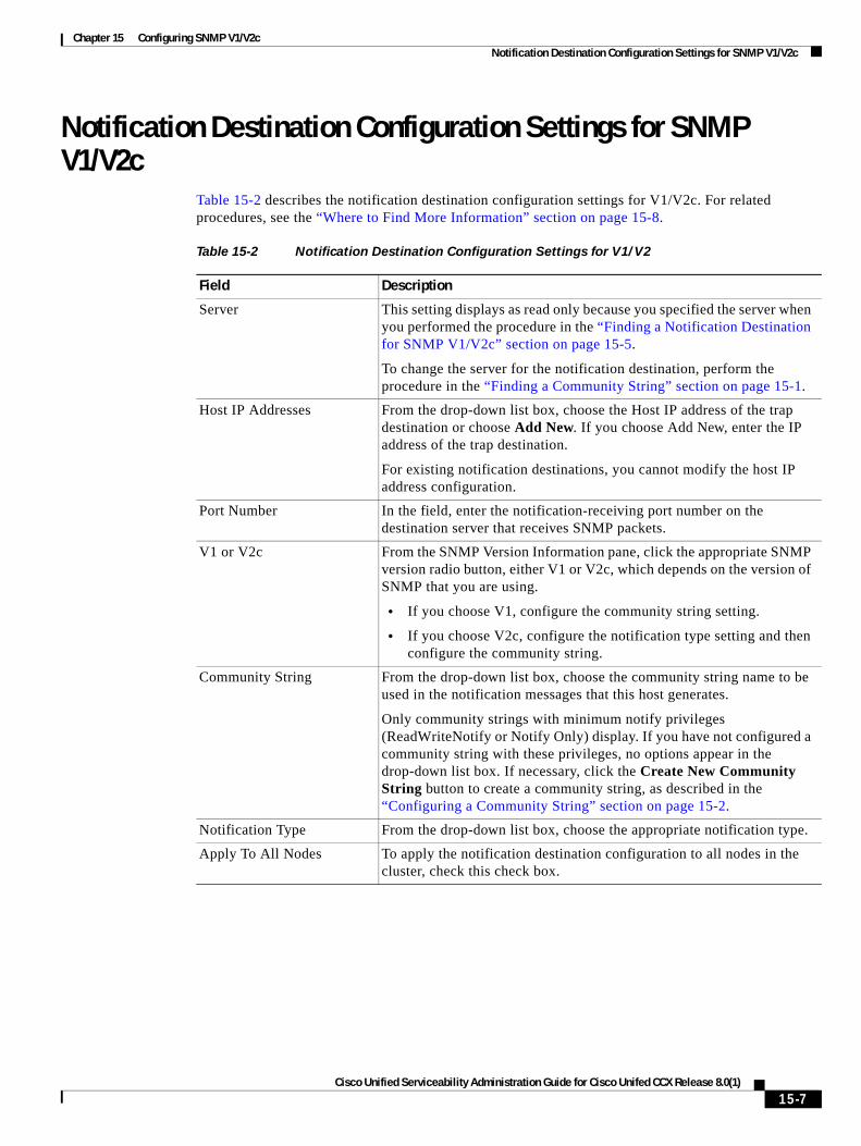
Chapter 15 Configuring SNMP V1/V2c Notification Destination Configuration Settings for SNMP V1/V2c
Notification Destination Configuration Settings for SNMP V1/V2c
Table 15-2 describes the notification destination configuration settings for V1/V2c. For related procedures, see the “Where to Find More Information” section on page 15-8.
Table 15-2 Notification Destination Configuration Settings for V1/V2
Field Description
Server This setting displays as read only because you specified the server when you performed the procedure in the “Finding a Notification Destination for SNMP V1/V2c” section on page 15-5.
To change the server for the notification destination, perform the procedure in the “Finding a Community String” section on page 15-1.
Host IP Addresses From the drop-down list box, choose the Host IP address of the trap destination or choose Add New. If you choose Add New, enter the IP address of the trap destination.
For existing notification destinations, you cannot modify the host IP address configuration.
Port Number In the field, enter the notification-receiving port number on the destination server that receives SNMP packets.
V1 or V2c From the SNMP Version Information pane, click the appropriate SNMP version radio button, either V1 or V2c, which depends on the version of SNMP that you are using.
• If you choose V1, configure the community string setting.
• If you choose V2c, configure the notification type setting and then configure the community string.
Community String From the drop-down list box, choose the community string name to be used in the notification messages that this host generates.
Only community strings with minimum notify privileges (ReadWriteNotify or Notify Only) display. If you have not configured a community string with these privileges, no options appear in the drop-down list box. If necessary, click the Create New Community String button to create a community string, as described in the “Configuring a Community String” section on page 15-2.
Notification Type From the drop-down list box, choose the appropriate notification type.
Apply To All Nodes To apply the notification destination configuration to all nodes in the cluster, check this check box.
15-7Cisco Unified Serviceability Administration Guide for Cisco Unifed CCX Release 8.0(1)

Chapter 15 Configuring SNMP V1/V2c Deleting a Notification Destination for SNMP V1/V2c
Deleting a Notification Destination for SNMP V1/V2cTo delete a notification destination, perform the following procedure:
Procedure
Step 1 Locate the notification destination, as described in the “Finding a Notification Destination for SNMP V1/V2c” section on page 15-5.
Step 2 From the list of matching records, check the check box next to the notification destination that you want to delete.
Step 3 Click Delete Selected.
Step 4 A message asks whether you want to delete the notification entries. To continue the deletion, click OK.
Step 5 A message indicates that changes will not take effect until you restart the SNMP master agent. To continue the configuration without restarting the SNMP master agent, click Cancel. To restart the SNMP master agent service, click OK.
Tip Cisco recommends that you wait until you finish all the SNMP configuration before you restart the SNMP master agent service. For information on how to restart the service, see the “Configuring Services” section on page 11-1.
After the window refreshes, the notification destination that you deleted no longer displays in the results.
Additional Information
See the “Where to Find More Information” section on page 15-8.
Where to Find More InformationRelated Topics
• Understanding Simple Network Management Protocol, page 14-1
• Finding a Community String, page 15-1
• Configuring a Community String, page 15-2
• Community String Configuration Settings, page 15-3
• Deleting a Community String, page 15-4
• SNMP Notification Destination, page 15-5
• Finding a Notification Destination for SNMP V1/V2c, page 15-5
• Configuring a Notification Destination for SNMP V1/V2c, page 15-6
• Notification Destination Configuration Settings for SNMP V1/V2c, page 15-7
• Deleting a Notification Destination for SNMP V1/V2c, page 15-8
• Configuring SNMP V3, page 16-1
• Configuring SNMP System Group, page 17-1
15-8Cisco Unified Serviceability Administration Guide for Cisco Unifed CCX Release 8.0(1)
Cisco Unified Serviceability Admin
C H A P T E R 16
Configuring SNMP V3This chapter, which describes how to configure SNMP v3, so the network management system can monitor Cisco Unified CCX, contains the following topics:
• Finding the SNMP User, page 16-1
• Configuring the SNMP User, page 16-2
• SNMP User Configuration Settings, page 16-3
• Deleting the SNMP User, page 16-4
• Finding a Notification Destination for SNMP V3, page 16-5
• Configuring a Notification Destination for SNMP V3, page 16-6
• Notification Destination Configuration Settings for SNMP V3, page 16-7
• Where to Find More Information, page 16-8
Tip If you use SNMP v1 or v2c, see the “Configuring SNMP V1/V2c” section on page 15-1.
Finding the SNMP User
Tip The Add New button does not display in the SNMP User Configuration window until you click the Find button. If no users exist and you want to add a user, click the Find button and wait for the window to refresh. The Add New button displays.
To find a SNMP user, perform the following procedure:
Procedure
Step 1 Choose Snmp > V3 > User.
The SNMP User Configuration window displays.
Step 2 From the Find User where Name list box, choose the specific search criteria that you want to use to find the user; for example, begins with.
Step 3 Enter the user name for which you want to search.
16-1istration Guide for Cisco Unifed CCX Release 8.0(1)
Chapter 16 Configuring SNMP V3 Configuring the SNMP User
Step 4 From the Server drop-down list box, choose the hostname or IP address of the server where you access the user.
Step 5 Click Find.
After you click the Find button, the Add New button displays. After the search results display, the Apply to All Nodes check box displays.
Step 6 Unified CM clusters only: If you want to apply the configuration from one of the options in the search results to all nodes in the cluster, check the check box next to the name of the option and check the Apply to All Nodes check box.
Step 7 From the list of results, click the user that you want to view.
Step 8 To add or update a user, see the “Configuring the SNMP User” section on page 16-2.
Additional Information
See the “Related Topics” section on page 16-8.
Configuring the SNMP UserTo configure user(s) for SNMP, perform the following procedure:
Procedure
Step 1 Perform the procedure in the “Finding a Notification Destination for SNMP V3” section on page 16-5.
Step 2 Perform one of the following tasks:
• To add a new SNMP user, click the Add New button in the SNMP User Configuration Find/List window and go to Step 3.
• To modify an existing SNMP user, locate the user, as described in the “Finding a Notification Destination for SNMP V3” section on page 16-5; click the name of the SNMP user that you want to edit and go to Step 3.
• To delete an SNMP user, see the “Deleting the SNMP User” section on page 16-4.
Step 3 Enter the configuration settings, as described in Table 16-1.
Tip Before you save the configuration, you can click the Clear All button at any time to delete all information that you entered for all settings in the window.
Step 4 To add a new user, click Insert, or click Save to save changes to an existing user.
Step 5 A message indicates that changes will not take effect until you restart the SNMP master agent. To continue the configuration without restarting the SNMP master agent, click Cancel. To restart the SNMP master agent service, click OK.
Tip Cisco recommends that you wait until you finish the SNMP configuration before you restart the SNMP master agent service. For information on how to restart the service, see the “Configuring Services” section on page 11-1.
16-2Cisco Unified Serviceability Administration Guide for Cisco Unifed CCX Release 8.0(1)
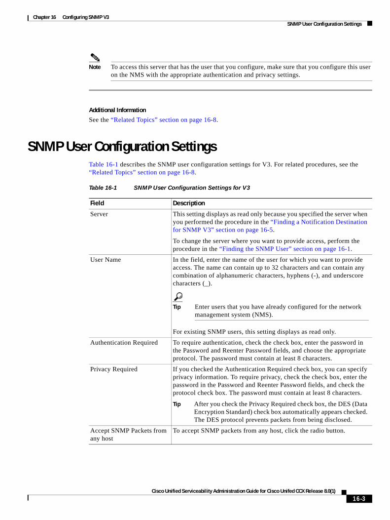
Chapter 16 Configuring SNMP V3 SNMP User Configuration Settings
Note To access this server that has the user that you configure, make sure that you configure this user on the NMS with the appropriate authentication and privacy settings.
Additional Information
See the “Related Topics” section on page 16-8.
SNMP User Configuration SettingsTable 16-1 describes the SNMP user configuration settings for V3. For related procedures, see the “Related Topics” section on page 16-8.
Table 16-1 SNMP User Configuration Settings for V3
Field Description
Server This setting displays as read only because you specified the server when you performed the procedure in the “Finding a Notification Destination for SNMP V3” section on page 16-5.
To change the server where you want to provide access, perform the procedure in the “Finding the SNMP User” section on page 16-1.
User Name In the field, enter the name of the user for which you want to provide access. The name can contain up to 32 characters and can contain any combination of alphanumeric characters, hyphens (-), and underscore characters (_).
Tip Enter users that you have already configured for the network management system (NMS).
For existing SNMP users, this setting displays as read only.
Authentication Required To require authentication, check the check box, enter the password in the Password and Reenter Password fields, and choose the appropriate protocol. The password must contain at least 8 characters.
Privacy Required If you checked the Authentication Required check box, you can specify privacy information. To require privacy, check the check box, enter the password in the Password and Reenter Password fields, and check the protocol check box. The password must contain at least 8 characters.
Tip After you check the Privacy Required check box, the DES (Data Encryption Standard) check box automatically appears checked. The DES protocol prevents packets from being disclosed.
Accept SNMP Packets from any host
To accept SNMP packets from any host, click the radio button.
16-3Cisco Unified Serviceability Administration Guide for Cisco Unifed CCX Release 8.0(1)
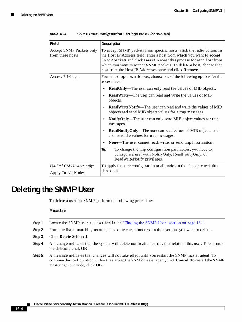
Chapter 16 Configuring SNMP V3 Deleting the SNMP User
Deleting the SNMP UserTo delete a user for SNMP, perform the following procedure:
Procedure
Step 1 Locate the SNMP user, as described in the “Finding the SNMP User” section on page 16-1.
Step 2 From the list of matching records, check the check box next to the user that you want to delete.
Step 3 Click Delete Selected.
Step 4 A message indicates that the system will delete notification entries that relate to this user. To continue the deletion, click OK.
Step 5 A message indicates that changes will not take effect until you restart the SNMP master agent. To continue the configuration without restarting the SNMP master agent, click Cancel. To restart the SNMP master agent service, click OK.
Accept SNMP Packets only from these hosts
To accept SNMP packets from specific hosts, click the radio button. In the Host IP Address field, enter a host from which you want to accept SNMP packets and click Insert. Repeat this process for each host from which you want to accept SNMP packets. To delete a host, choose that host from the Host IP Addresses pane and click Remove.
Access Privileges From the drop-down list box, choose one of the following options for the access level:
• ReadOnly—The user can only read the values of MIB objects.
• ReadWrite—The user can read and write the values of MIB objects.
• ReadWriteNotify—The user can read and write the values of MIB objects and send MIB object values for a trap messages.
• NotifyOnly—The user can only send MIB object values for trap messages.
• ReadNotifyOnly—The user can read values of MIB objects and also send the values for trap messages.
• None—The user cannot read, write, or send trap information.
Tip To change the trap configuration parameters, you need to configure a user with NotifyOnly, ReadNotifyOnly, or ReadWriteNotify privileges.
Unified CM clusters only:
Apply To All Nodes
To apply the user configuration to all nodes in the cluster, check this check box.
Table 16-1 SNMP User Configuration Settings for V3 (continued)
Field Description
16-4Cisco Unified Serviceability Administration Guide for Cisco Unifed CCX Release 8.0(1)
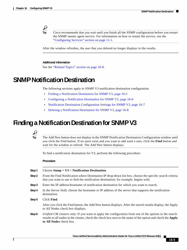
Chapter 16 Configuring SNMP V3 SNMP Notification Destination
Tip Cisco recommends that you wait until you finish all the SNMP configuration before you restart the SNMP master agent service. For information on how to restart the service, see the “Configuring Services” section on page 11-1.
After the window refreshes, the user that you deleted no longer displays in the results.
Additional Information
See the “Related Topics” section on page 16-8.
SNMP Notification DestinationThe following sections apply to SNMP V3 notification destination configuration.
• Finding a Notification Destination for SNMP V3, page 16-5
• Configuring a Notification Destination for SNMP V3, page 16-6
• Notification Destination Configuration Settings for SNMP V3, page 16-7
• Deleting a Notification Destination for SNMP V3, page 16-8
Finding a Notification Destination for SNMP V3
Tip The Add New button does not display in the SNMP Notification Destination Configuration window until you click the Find button. If no users exist and you want to add want a user, click the Find button and wait for the window to refresh. The Add New button displays.
To find a notification destination for V3, perform the following procedure:
Procedure
Step 1 Choose Snmp > V3 > Notification Destination.
Step 2 From the Find Notification where Destination IP drop-down list box, choose the specific search criteria that you want to use to find the notification destination; for example, begins with.
Step 3 Enter the IP address/hostname of notification destination for which you want to search.
Step 4 In the Server field, choose the hostname or IP address of the server that supports the notification destination.
Step 5 Click Find.
After you click the Find button, the Add New button displays. After the search results display, the Apply to All Nodes check box displays.
Step 6 Unified CM clusters only: If you want to apply the configuration from one of the options in the search results to all nodes in the cluster, check the check box next to the name of the option and check the Apply to All Nodes check box.
16-5Cisco Unified Serviceability Administration Guide for Cisco Unifed CCX Release 8.0(1)
Chapter 16 Configuring SNMP V3 Configuring a Notification Destination for SNMP V3
Step 7 From the list of results, click the notification destination that you want to view.
Step 8 To add or update a notification destination, see the “Configuring a Notification Destination for SNMP V3” section on page 16-6.
Additional Information
See the “Related Topics” section on page 16-8.
Configuring a Notification Destination for SNMP V3To configure the trap receiver, perform the following procedure:
Procedure
Step 1 Perform the procedure in the “Finding a Notification Destination for SNMP V3” section on page 16-5.
Step 2 Perform one of the following tasks:
• To add a new SNMP notification destination, click the Add New button in the search results window and go to Step 3.
• To modify an existing SNMP notification destination, locate the notification destination in the search results window; click the name of the SNMP notification destination that you want to edit and go to Step 3.
• To delete an SNMP notification destination, see the “Deleting a Notification Destination for SNMP V3” section on page 16-8.
Step 3 Configure the settings, as described in Table 16-2.
Tip Before you save the configuration, you can click the Clear button at any time to delete all information that you entered for all settings in the window.
Step 4 To save a notification destination, click Insert, or click Save to save changes to an existing notification destination.
Step 5 A message indicates that changes will not take effect until you restart the SNMP master agent. To continue the configuration without restarting the SNMP master agent, click Cancel. To restart the SNMP master agent service, click OK.
Tip Cisco recommends that you wait until you finish the SNMP configuration before you restart the SNMP master agent service. For information on how to restart the service, see the “Configuring Services” section on page 11-1.
Additional Information
See the “Related Topics” section on page 16-8.
16-6Cisco Unified Serviceability Administration Guide for Cisco Unifed CCX Release 8.0(1)
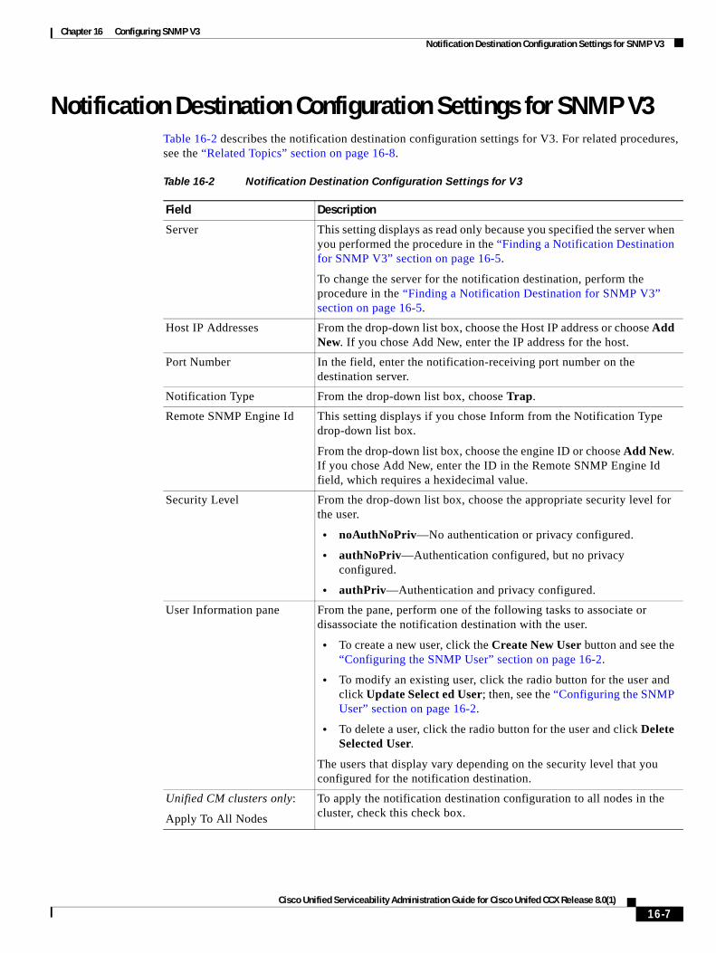
Chapter 16 Configuring SNMP V3 Notification Destination Configuration Settings for SNMP V3
Notification Destination Configuration Settings for SNMP V3Table 16-2 describes the notification destination configuration settings for V3. For related procedures, see the “Related Topics” section on page 16-8.
Table 16-2 Notification Destination Configuration Settings for V3
Field Description
Server This setting displays as read only because you specified the server when you performed the procedure in the “Finding a Notification Destination for SNMP V3” section on page 16-5.
To change the server for the notification destination, perform the procedure in the “Finding a Notification Destination for SNMP V3” section on page 16-5.
Host IP Addresses From the drop-down list box, choose the Host IP address or choose Add New. If you chose Add New, enter the IP address for the host.
Port Number In the field, enter the notification-receiving port number on the destination server.
Notification Type From the drop-down list box, choose Trap.
Remote SNMP Engine Id This setting displays if you chose Inform from the Notification Type drop-down list box.
From the drop-down list box, choose the engine ID or choose Add New. If you chose Add New, enter the ID in the Remote SNMP Engine Id field, which requires a hexidecimal value.
Security Level From the drop-down list box, choose the appropriate security level for the user.
• noAuthNoPriv—No authentication or privacy configured.
• authNoPriv—Authentication configured, but no privacy configured.
• authPriv—Authentication and privacy configured.
User Information pane From the pane, perform one of the following tasks to associate or disassociate the notification destination with the user.
• To create a new user, click the Create New User button and see the “Configuring the SNMP User” section on page 16-2.
• To modify an existing user, click the radio button for the user and click Update Select ed User; then, see the “Configuring the SNMP User” section on page 16-2.
• To delete a user, click the radio button for the user and click Delete Selected User.
The users that display vary depending on the security level that you configured for the notification destination.
Unified CM clusters only:
Apply To All Nodes
To apply the notification destination configuration to all nodes in the cluster, check this check box.
16-7Cisco Unified Serviceability Administration Guide for Cisco Unifed CCX Release 8.0(1)
Chapter 16 Configuring SNMP V3 Deleting a Notification Destination for SNMP V3
Deleting a Notification Destination for SNMP V3To delete a notification destination, perform the following procedure:
Procedure
Step 1 Locate the SNMP notification destination, as described in the “Finding a Notification Destination for SNMP V3” section on page 16-5.
Step 2 From the list of matching records, check the check box next to the notification destination that you want to delete.
Step 3 Click Delete Selected.
Step 4 A message asks you if you want to delete the notification destination. To continue the deletion, click OK.
Step 5 A message indicates that changes will not take effect until you restart the SNMP master agent. To continue the configuration without restarting the SNMP master agent, click Cancel. To restart the SNMP master agent service, click OK.
Tip Cisco recommends that you wait until you finish all the SNMP configuration before you restart the SNMP master agent service. For information on how to restart the service, see the “Configuring Services” section on page 11-1.
After the window refreshes, the notification destination that you deleted no longer displays in the search results window.
Additional Information
See the “Related Topics” section on page 16-8.
Where to Find More InformationRelated Topics
• Understanding Simple Network Management Protocol, page 14-1
• Finding the SNMP User, page 16-1
• Configuring the SNMP User, page 16-2
• SNMP User Configuration Settings, page 16-3
• Deleting the SNMP User, page 16-4
• Finding a Notification Destination for SNMP V3, page 16-5
• Configuring a Notification Destination for SNMP V3, page 16-6
• Notification Destination Configuration Settings for SNMP V3, page 16-7
• Deleting a Notification Destination for SNMP V3, page 16-8
• Configuring SNMP V1/V2c, page 15-1
• Configuring SNMP System Group, page 17-1
16-8Cisco Unified Serviceability Administration Guide for Cisco Unifed CCX Release 8.0(1)
Cisco Unified Serviceability Admin
C H A P T E R 17
Configuring SNMP System GroupCisco Unified Serviceability provides the MIB2 System Group Configuration window where you can configure the system contact and system location objects for the MIB-II system group. For example, you could enter Administrator, 555-121-6633, for the system contact and San Jose, Bldg 23, 2nd floor, for the system location. This chapter contains information on the following topics:
• Configuring the MIB2 System Group, page 17-1
• MIB2 System Group Configuration Settings, page 17-2
• Where to Find More Information, page 17-2
Configuring the MIB2 System GroupPerform the following procedure to configure a system contact and system location for the MIB-II system group.
Tip This procedure supports SNMP v1, v2c, and v3 configuration.
Procedure
Step 1 Choose Snmp > SystemGroup > MIB2 System Group.
Step 2 Configure the settings, as described in Table 17-1.
Step 3 Click Save.
Step 4 A message indicates that changes will not take effect until you restart the SNMP master agent. To continue the configuration without restarting the SNMP master agent service, click Cancel. To restart the SNMP master agent service, click OK.
Note To clear the System Contact and System Location fields, click the Clear All button. To delete the system configuration, click the Clear All button and the Save button.
Additional Information
See the “Related Topics” section on page 17-2.
17-1istration Guide for Cisco Unifed CCX Release 8.0(1)
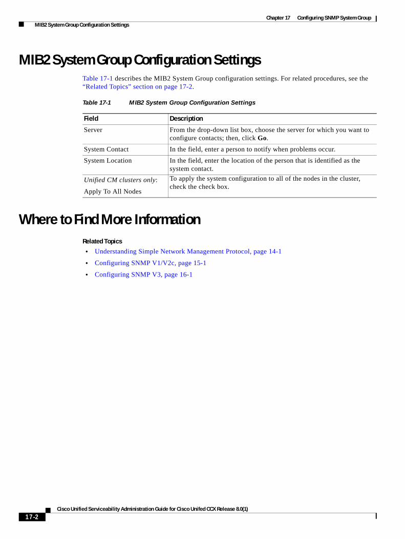
Chapter 17 Configuring SNMP System Group MIB2 System Group Configuration Settings
MIB2 System Group Configuration SettingsTable 17-1 describes the MIB2 System Group configuration settings. For related procedures, see the “Related Topics” section on page 17-2.
Where to Find More InformationRelated Topics
• Understanding Simple Network Management Protocol, page 14-1
• Configuring SNMP V1/V2c, page 15-1
• Configuring SNMP V3, page 16-1
Table 17-1 MIB2 System Group Configuration Settings
Field Description
Server From the drop-down list box, choose the server for which you want to configure contacts; then, click Go.
System Contact In the field, enter a person to notify when problems occur.
System Location In the field, enter the location of the person that is identified as the system contact.
Unified CM clusters only:
Apply To All Nodes
To apply the system configuration to all of the nodes in the cluster, check the check box.
17-2Cisco Unified Serviceability Administration Guide for Cisco Unifed CCX Release 8.0(1)
Cisco Unified Serviceability Admin
C H A P T E R 18
Configuring SNMP Trap ParametersThis section describes how to use CLI commands to set configurable trap settings. Table 14-3 provides the SNMP trap configuration parameters and recommended configuration for CISCO-SYSLOG-MIB. This chapter provides information on the following topic:
• Configuring CISCO-SYSLOG-MIB Trap Parameters, page 18-1
Configuring CISCO-SYSLOG-MIB Trap ParametersUse these guidelines to configure CISCO-SYSLOG-MIB trap settings on your system:
• Set clogsNotificationEnabled (1.3.6.1.4.1.9.9.41.1.1.2) to true by using the SNMP Set operation; for example, use the net-snmp set utility to set this OID to true from the linux command line using: snmpset -c <community string> -v2c <transmitter ipaddress> 1.3.6.1.4.1.9.9.41.1.1.2.0 i 1
You can also use any other SNMP management application for the SNMP Set operation.
• Set clogMaxSeverity (1.3.6.1.4.1.9.9.41.1.1.3) value by using the SNMP Set operation; for example, use the net-snmp set utility to set this OID value from the linux command line using: snmpset -c public -v2c 1<transmitter ipaddress> 1.3.6.1.4.1.9.9.41.1.1.3.0 i <value>
Enter a severity number for the <value> setting. Severity values increase as severity decreases. A value of 1 (Emergency) indicates highest severity, and a value of 8 (Debug) indicates lowest severity. Syslog agent ignores any messages greater than the value that you specify; for example, to trap all syslog messages, use a value of 8.
You can also use any other SNMP management application for the SNMP Set operation.
Note Before logging, Syslog truncates any trap message data that is larger than the specified Syslog buffer size. The Syslog trap message length limitation equals 255 bytes.
Where to Find More InformationRelated Topics
• Understanding Services, page 9-1
• Configuring Services, page 11-1
• Configuring SNMP Trap Parameters, page 18-1
18-1istration Guide for Cisco Unifed CCX Release 8.0(1)
Chapter 18 Configuring SNMP Trap Parameters Where to Find More Information
• Configuring SNMP V1/V2c, page 15-1
• Configuring SNMP V3, page 16-1
• Configuring SNMP System Group, page 17-1
Related Documentation
Command Line Interface Reference Guide for Cisco Unified CCX
18-2Cisco Unified Serviceability Administration Guide for Cisco Unifed CCX Release 8.0(1)
Cisco Unified Serviceability Admi
I N D E X
finding 16-5
A
accessibility features 2-6
accessing
CAR 2-5
web interface 2-1
A Cisco DB service 9-5
alarm definitions
creating user-defined text for 5-1
overview 3-2
searching for and viewing 5-1
System Alarm Catalog 5-2
alarms
configuration checklist 3-3
configuration overview 3-2
configuring 4-1
definitions 3-2
NT Event Viewer 4-3
overview 3-1
SDI trace library 4-3
service groups for 4-3
Syslog 4-3
System Alarm Catalog 5-2
updating 4-1
viewing information 3-3
alert summary report 10-4
audit log
configuration settings (table) 13-2
configuring 13-2
understanding 13-1
where to find more information 13-4
B
browser support 1-3
C
Cisco AMC Service 9-3
Cisco AXL Web Service 9-2
Cisco CallManager Serviceability service 9-4
Cisco CDP Agent service 9-5
CISCO-CDP-MIB 14-6
Cisco CDP service 9-4
Cisco Certificate Expiry Monitor service 9-6
Cisco Database Layer Monitor service 9-6
Cisco DB service 9-5
Cisco DRF Local 9-4
Cisco DRF Master 9-4
Cisco Log Partition Monitoring Tool service 9-3
Cisco RIS Data Collector service 9-3
Cisco RTMT Reporter Servlet 9-3
Cisco Serviceability Reporter service 9-2
Cisco SOAP-Log Collection APIs 9-7
Cisco SOAP-Performance Monitoring APIs service 9-7
Cisco SOAP-Real-Time Service APIs service 9-7
Cisco Syslog Agent service 9-6
CISCO-SYSLOG-MIB 14-7
trap parameters
configuring 18-1
Cisco Tomcat service 9-5
Cisco Tomcat Stats Servlet 9-3
Cisco Trace Collection Service 9-4
IN-1nistration for Cisco Unifed CCX Release 8.0(1)Guide
Index
Cisco Trace Collection Servlet 9-4
Cisco Trust Verification Service 9-6
Cisco UXL Web Service 9-2
CLI
starting services 11-4
stopping services 11-4
cluster
service activation recommendations 11-2
community strings
configuration settings 15-3
configuring 15-2
deleting 15-4
description 14-4
finding 15-1
Control Center
feature services 9-7
network services 9-7
overview 9-7
starting services 9-7, 11-3
stopping services 9-7, 11-3
viewing service status 9-7
viewing status 11-3
D
debug trace levels
Database Layer Monitor fields 7-5
RIS Data Collector fields 7-6
service settings 7-4
servlet settings 7-5
device name based trace monitoring 7-1
F
feature services
activating 9-1, 11-1
configuration checklist 9-8
deactivating 11-1
IN-2Cisco Unified Serviceability Administration for Cisco Unifed CCX R
overview 9-1
starting 9-1, 11-3
stopping 9-1, 11-3
viewing status 9-1, 11-3
H
Host Resources Agent service 9-5
HOST-RESOURCES MIB 14-7
HTTPS
overview (IE and Netscape) 2-2
saving certificate to trusted folder (IE) 2-3, 2-4
I
informs
configuration parameters 14-5
configuration settings 15-7, 16-7
configuring 15-6, 16-6
deleting 15-8, 16-8
finding 15-5
L
logging out of interface 2-5
M
Management Information Base (MIB)
CISCO-SYSLOG-MIB 14-7
HOST-RESOURCES MIB 14-7
MIB-II 14-7
overview 14-5
SYSAPPL-MIB 14-6
MIB2 Agent service 9-5
MIB2 system group
configuring 17-1
MIB-II 14-7
elease 8.0(1)Guide
Index
N
navigating to other web interfaces 2-5
Network Agent Adaptor service 9-5
network services
Control Center 9-2
overview 9-2
starting 9-2, 11-3
stopping 9-2, 11-3
viewing status 9-2, 11-3
notification destination (V1/V2)
configuration settings 15-7
configuring 15-6
deleting 15-8
finding 15-5
notification destination (V3)
configuration settings 16-7
configuring 16-6
deleting 16-8
finding 16-5
NT Event Viewer 4-3
O
output settings for trace 7-7
overview
accessibility features 2-6
accessing CAR 2-5
accessing Dialed Number Analyzer 2-5
accessing online help 2-5
accessing web interface 2-1
alarm definitions 3-2
alarms 3-1
browser support 1-3
CAR 1-2
Cisco Unified Serviceability 1-1
Dialed Number Analyzer 1-2
feature services 9-1
HTTPS 2-2
Cisco Unified Serviceabi
logging out of interface 2-5
MIBs 14-5
navigating to other web interfaces 2-5
network services 9-2
remote serviceability 1-2
RTMT 1-2
serviceability archive reports 10-1
serviceability reports archive 10-1
SNMP 14-1
trace 6-1
trace collection 6-2
traps 14-4
troubleshooting trace settings 6-2
verifying version 2-5
R
Real-Time Monitoring Tool
alert summary report 10-4
server statistics report 10-2
service 9-3
Cisco AMC Service 9-3
Cisco CallManager Serviceability RTMT 9-3
Cisco Log Partition Monitoring Tool 9-3
Cisco RIS Data Collector 9-3
Cisco RTMT Reporter Servlet 9-3
Cisco Tomcat Stats Servlet 9-3
serviceability reports archive
service parameters 10-2
remote serviceability 1-2
report
alert summary 10-4
server statistics 10-2
reporting tools 1-2
overview 1-2
IN-3lity Administration for Cisco Unifed CCX Release 8.0(1)Guide
Index
S
security
HTTPS for IE 6 2-3
HTTPS for IE 7 2-4
server statistics report 10-2
service
A Cisco DB 9-5
activating 11-1
activating trace 7-1
Cisco AMC Service 9-3
Cisco AXL Web Service 9-2
Cisco CallManager Serviceability 9-4
Cisco CallManager Serviceability RTMT 9-3
Cisco CDP 9-4
Cisco CDP Agent 9-5
Cisco Certificate Expiry Monitor 9-6
Cisco Database Layer Monitor 9-6
Cisco DRF Local 9-4
Cisco DRF Master 9-4
Cisco Log Partition Monitoring Tool 9-3
Cisco RIS Data Collector 9-3
Cisco RTMT Reporter Servlet 9-3
Cisco Serviceability Reporter 9-2
Cisco SOAP-Log Collection APIs 9-7
Cisco SOAP-Performance Monitoring APIs 9-7
Cisco SOAP-Real-Time Service APIs 9-7
Cisco Syslog Agent 9-6
Cisco Tomcat 9-5
Cisco Tomcat Stats Servlet 9-3
Cisco Trace Collection Service 9-4
Cisco Trace Collection Servlet 9-4
Cisco Trust Verification Service 9-6
Cisco UXL Web Service 9-2
configuration checklist 9-8
configuring alarms for 4-1
Control Center overview 9-7
deactivating 11-1
debug trace levels 7-4
IN-4Cisco Unified Serviceability Administration for Cisco Unifed CCX R
feature services 9-1
Host Resources Agent 9-5
MIB2 Agent 9-5
Native Agent Adaptor 9-5
network services 9-2
SNMP Master Agent 9-5
starting 11-3
starting services 9-7
stopping 11-3
stopping services 9-7
System Application Agent 9-5
viewing service status 9-7
viewing status 11-3
serviceability reports archive
alert summary report 10-4
configuration checklist 10-6
configuring 12-1
overview 10-1
server statistic report 10-2
service parameters 10-2
service activation
activating 11-1
deactivating 11-1
recommendations for a cluster 11-2
service groups
alarms 4-3
for trace 7-3
services
trace field descriptions 7-5
servlet
debug trace levels 7-5
Simple Network Management Protocol
see SNMP 14-1
SNMP
basics 14-1, 14-2
CISCO-SYSLOG-MIB trap parameters
configuring 18-1
community strings
configuration settings 15-3
elease 8.0(1)Guide
Index
configuring 15-2
deleting 15-4
description 14-4
finding 15-1
configuration checklist 14-9
configuration requirements 14-2
finding 16-5
informs
configuration parameters 14-5
configuration settings 15-7, 16-7
configuring 15-6, 16-6
deleting 15-8, 16-8
finding 15-5
Management Information Base (MIB) 14-5
MIB 14-5
MIB2 system group
configuring 17-1
notification destination (V1/V2)
configuration settings 15-7
configuring 15-6
deleting 15-8
finding 15-5
notification destination (V3)
configuration settings 16-7
configuring 16-6
deleting 16-8
finding 16-5
overview 14-1
remote monitoring with 14-1
service
Cisco CDP Agent 9-5
Cisco Syslog Agent 9-6
Host Resources Agent 9-5
MIB2 Agent 9-5
Network Agent Adaptor 9-5
SNMP Master Agent 9-5
System Application Agent 9-5
services 14-3
SNMPv1 14-2
Cisco Unified Serviceabi
SNMPv2c 14-3
SNMPv3 14-3
trace configuration 14-9
traps
configuration parameters 14-5
configuration settings 15-7, 16-7
configuring 15-6, 16-6
deleting 15-8, 16-8
finding 15-5, 16-5
overview 14-4
user
configuration settings 16-3
configuring 16-2
deleting 16-4
description 14-4
finding 16-1
SNMP Master Agent service 9-5
SOAP
service
Cisco SOAP-Log Collection APIs 9-7
Cisco SOAP-Performance Monitoring APIs 9-7
Cisco SOAP-Real-Time Service APIs 9-7
SYSAPPL-MIB 14-6
System Alarm Catalog 5-2
System Application Agent service 9-5
T
trace
Cisco Database Layer Monitor service
trace fields 7-5
Cisco RIS Data Collector service
trace fields 7-6
collection 6-2
configuration and collection checklist 6-3
configuration overview 6-1
configuring 7-1
debug trace levels for service 7-4
debug trace levels for servlet 7-5
IN-5lity Administration for Cisco Unifed CCX Release 8.0(1)Guide
Index
device name based trace monitoring 7-1
output settings 7-7
overview 6-1
recommendations for SNMP 14-9
service groups for 7-3
trace and log central 6-2
trace field descriptions 7-5
troubleshooting trace settings 6-2, 8-1
trace collection 6-2
traps
configuration parameters 14-5
configuration settings 15-7, 16-7
configuring 15-6, 16-6
deleting 15-8, 16-8
finding 15-5, 16-5
overview 14-4
troubleshooting
trace settings 6-2, 8-1
U
user-defined alarm descriptions 5-1
users (SNMP)
configuration settings 16-3
configuring 16-2
deleting 16-4
description 14-4
finding 16-1
V
viewing alarm information 3-3
IN-6Cisco Unified Serviceability Administration for Cisco Unifed CCX R
elease 8.0(1)Guide