Embed Size (px)
Citation preview
Americas HeadquartersCisco Systems, Inc.170 West Tasman DriveSan Jose, CA 95134-1706 USAhttp://www.cisco.comTel: 408 526-4000
800 553-NETS (6387)Fax: 408 527-0883
Cisco Video Surveillance IP Camera Configuration GuideRelease 1.1.1
Text Part Number: OL-28116-01
NOTICE. ALL STATEMENTS, INFORMATION, AND RECOMMENDATIONS IN THIS MANUAL ARE BELIEVED TO BE ACCURATE BUT ARE PRESENTED WITHOUT WARRANTY OF ANY KIND, EXPRESS OR IMPLIED. USERS MUST TAKE FULL RESPONSIBILITY FOR THEIR APPLICATION OF ANY PRODUCTS.
THE SOFTWARE LICENSE AND LIMITED WARRANTY FOR THE ACCOMPANYING PRODUCT ARE SET FORTH IN THE INFORMATION PACKET THAT SHIPPED WITH THE PRODUCT AND ARE INCORPORATED HEREIN BY THIS REFERENCE. IF YOU ARE UNABLE TO LOCATE THE SOFTWARE LICENSE OR LIMITED WARRANTY, CONTACT YOUR CISCO REPRESENTATIVE FOR A COPY.
The Cisco implementation of TCP header compression is an adaptation of a program developed by the University of California, Berkeley (UCB) as part of UCB’s public domain version of the UNIX operating system. All rights reserved. Copyright © 1981, Regents of the University of California.
NOTWITHSTANDING ANY OTHER WARRANTY HEREIN, ALL DOCUMENT FILES AND SOFTWARE OF THESE SUPPLIERS ARE PROVIDED “AS IS” WITH ALL FAULTS. CISCO AND THE ABOVE-NAMED SUPPLIERS DISCLAIM ALL WARRANTIES, EXPRESSED OR IMPLIED, INCLUDING, WITHOUT LIMITATION, THOSE OF MERCHANTABILITY, FITNESS FOR A PARTICULAR PURPOSE AND NONINFRINGEMENT OR ARISING FROM A COURSE OF DEALING, USAGE, OR TRADE PRACTICE.
IN NO EVENT SHALL CISCO OR ITS SUPPLIERS BE LIABLE FOR ANY INDIRECT, SPECIAL, CONSEQUENTIAL, OR INCIDENTAL DAMAGES, INCLUDING, WITHOUT LIMITATION, LOST PROFITS OR LOSS OR DAMAGE TO DATA ARISING OUT OF THE USE OR INABILITY TO USE THIS MANUAL, EVEN IF CISCO OR ITS SUPPLIERS HAVE BEEN ADVISED OF THE POSSIBILITY OF SUCH DAMAGES.
Cisco and the Cisco Logo are trademarks of Cisco Systems, Inc. and/or its affiliates in the U.S. and other countries. A listing of Cisco's trademarks can be found at www.cisco.com/go/trademarks. Third party trademarks mentioned are the property of their respective owners. The use of the word partner does not imply a partnership relationship between Cisco and any other company. (1005R)
Cisco Video Surveillance IP Camera Configuration Guide, Release 1.1.1 Copyright © 2012 Cisco Systems, Inc. All rights reserved.
OL-28116-01
C O N T E N T S
Preface v
Overview v
Organization v
Obtaining Documentation, Obtaining Support, and Security Guidelines vi
C H A P T E R 1 Overview 1-1
IP Camera Features 1-1
Accessing the IP Camera 1-2
Understanding the IP Camera User Interface 1-3
IP Camera Window Links 1-4
IP Camera Windows 1-4
C H A P T E R 2 Performing the Initial Setup of the IP Camera 2-1
C H A P T E R 3 Viewing Live Video 3-1
C H A P T E R 4 Feature Setup 4-1
Streaming Window 4-1
Camera Window 4-5
Video Overlay Window 4-7
IO Ports Window 4-8
Event Notification Window 4-9
C H A P T E R 5 Network Setup 5-1
Basic Window 5-1
IP Addressing Window 5-2
Time Window 5-4
Discovery Window 5-5
IP Filter Window 5-6
QoS Window 5-7
iiiCisco Video Surveillance IP Camera Configuration Guide, Release 1.1.1
Contents
C H A P T E R 6 Administration 6-1
Initialization Window 6-1
User Window 6-3
Maintenance Window 6-4
Firmware Window 6-6
Device Processes Window 6-7
Password Complexity Window 6-8
C H A P T E R 7 Log Configuration 7-1
Log Setup Window 7-1
Local Log Window 7-4
I N D E X
ivCisco Video Surveillance IP Camera Configuration Guide, Release 1.1.1
OL-28116-01
Preface
OverviewThis document, Cisco Video Surveillance IP Camera Configuration Guide, Release 1.1.1, provides information about installing and deploying the Cisco Video Surveillance 6020 High-Definition IP Camera.
OrganizationThis manual is organized as follows:
Chapter 1, “Overview” Provides information about the IP camera features, instructions for accessing the user interface, and information about the user interface.
Chapter 2, “Performing the Initial Setup of the IP Camera”
Provides information and instructions about performing the initial setup of the IP Camera
Chapter 3, “Viewing Live Video” Provides information and instructions about viewing live video.
Chapter 4, “Feature Setup” Provides information and instructions for configuring IP camera features, such as streaming, camera capabilities, video overlay, I/O ports, and events.
Chapter 5, “Network Setup” Provides information and instructions for configuring network setting, such as IP addressing, time, discovery, IP filtering, and Quality of Service (QoS).
Chapter 6, “Administration” Provides information and instructions for performing administrative tasks, such as IP camera initialization, user management, maintenance, firmware upgrade, device processes management, and password complexity.
Chapter 7, “Log Configuration” Provides information and instructions for configuring and viewing logs.
vCisco Video Surveillance IP Camera Configuration Guide, Release 1.1.1
OL-28116-01
Preface
Obtaining Documentation, Obtaining Support, and Security Guidelines
For information about obtaining documentation, submitting a service request, and gathering additional information, see the monthly What’s New in Cisco Product Documentation, which also lists all new and revised Cisco technical documentation, at:
http://www.cisco.com/en/US/docs/general/whatsnew/whatsnew.html
Subscribe to the What’s New in Cisco Product Documentation as a Really Simple Syndication (RSS) feed and set content to be delivered directly to your desktop using a reader application. The RSS feeds are a free service and Cisco currently supports RSS version 2.0.
viCisco Video Surveillance IP Camera Configuration Guide, Release 1.1.1
OL-28116-01

Cisco Video SurveilOL-28116-01
C H A P T E R 1
OverviewThis chapter provides information about the Cisco Video Surveillance 6000 Series IP camera features, instructions for accessing the user interface, and information about the user interface. It includes the following topics:
• IP Camera Features, page 1-1
• Accessing the IP Camera, page 1-2
• Understanding the IP Camera User Interface, page 1-3
IP Camera FeaturesThe Cisco Video Surveillance IP Camera offers a feature-rich digital camera solution for a video surveillance system. The camera provides high-definition (HD) video and simultaneous H.264 and MJPEG compression, streaming up to 30 frames per second (fps) at 1080p (1920 x 1080) resolution.
In addition, the IP camera provides networking and security capabilities, including multicast support, hardware-based Advanced Encryption Standard (AES), and hardware-based Data Encryption Standard/Triple Data Encryption Standard (DES/3DES) encryption. The camera can be powered through an external power supply or by integrated Power over Ethernet (PoE).
The IP camera includes the following key features:
• H.264 and MJPEG compression—The IP camera can generate H.264 and MJPEG streams simultaneously.
• Progressive scan video—The IP camera captures each frame at its entire resolution using progressive scan rather than interlaced video capture, which captures each field of video.
• Analog video output—Supports analog video for all resolutions with 15 fps or lower with no secondary stream.
• Medianet—The IP camera supports the Auto Smartports feature of the Media Services Interface (MSI). MSI enables a camera to participate as an endpoint in the Cisco medianet architecture when connected to a medianet enabled switch.
• Day/night switch support—An IR-cut filter provides increased sensitivity in low-light conditions.
• Multi-protocol support—Supports these protocols: DHCP, FTP, HTTP, HTTPS, NTP, RTP, RTSP, SMTP, SNMP v2 and v3, SSL/TLS, and TCP/IP.
• Web-based management—You perform ongoing administration and management of the IP camera through web-based configuration menus.
1-1lance IP Camera Configuration Guide, Release 1.1.1
Chapter 1 OverviewAccessing the IP Camera
• Motion detection—The IP camera can detect motion in user-designated fields of view by analyzing changes in pixels and generate an alert if motion is detected.
• Flexible scheduling—You can configure the IP camera to respond to events that occur within a designated schedule.
• Syslog support—The IP camera can send log data to a Syslog server.
• IP address filter—You can designate IP addresses that can access the IP camera and IP addresses that cannot access the IP camera.
• User-definable HTTP/ HTTPS port number—Allows you to define the port that is used to connect to the camera through the Internet.
• DHCP support—The IP camera can automatically obtain its IP addresses in a network in which DHCP is enabled.
• Network Time Protocol (NTP) support—Allows the IP camera to calibrate its internal clock with a local or Internet time server.
• Support for C and CS mount lenses—The IP camera supports a variety of C and CS mount lenses.
• Power options—The IP camera can be powered with 12 volts DC or 24 volts AC, which is provided through an optional external power adapter, or through PoE (802.3af), which is provided through a supported switch.
• Camera access control—You can control access to IP camera configuration windows and live video by configuring various user types and log in credentials.
Accessing the IP CameraAfter you perform the initial configuration as described in the Chapter 2, “Performing the Initial Setup of the IP Camera,” follow the steps in this section each time that you want to access the IP camera windows to make configuration settings, view live video, or perform other activities.
You access these windows by connecting to the IP camera from any PC that is on the same network as the IP camera and that meets these requirements:
• Operating system—Microsoft Windows 7 (32-bit or 64-bit)
• Browser—Internet Explorer 8.0 (32-bit only)
You need this information to access the IP camera windows:
• IP address of the IP camera. By default, the IP camera attempts to obtain an IP address from a DHCP server in your network. If the IP camera cannot obtain an IP address through DHCP within 90 seconds of powering up or resetting, it uses the default IP address of 192.168.0.100.
• Port number, if other than the default value. Default port numbers for the IP camera are 443 for HTTPS and 80 for HTTP. The IP camera administrator can configure an HTTPS port and an HTTP port as described in the “Initialization Window” section on page 6-1.
• Your user name and password for the IP camera. The IP camera administrator configures user names and passwords as described in the “User Window” section on page 6-3.
To access the IP camera windows, perform the following these steps.
Before you Begin
The Microsoft .NET Framework version 2.0 or later must be installed on the PC that you use to connect to the IP camera. You can download the .NET Framework from the Microsoft website.
1-2Cisco Video Surveillance IP Camera Configuration Guide, Release 1.1.1
OL-28116-01
Chapter 1 OverviewUnderstanding the IP Camera User Interface
Procedure
Step 1 Start Internet Explorer and enter the following in the address field:
protocol://ip_address:port_number
where:
• protocol is HTTPS for a secure connection or HTTP for a non-secure connection. You can use HTTP only if you configure the camera to accept non-secure HTTP connections as described in Chapter 2, “Performing the Initial Setup of the IP Camera.”
• ip_address is the IP address of the IP camera. The default IP address is 192.168.0.100.
• port_number is the port number that is used for HTTPS or HTTP connections to the IP camera. You do not need to enter a port number if you are connecting through the default HTTPS port 443 or the default HTTP port 80.
For example,
• Enter the following for a secure connection if the IP address is 192.168.0.100 and the HTTPS port number is 443:
https://192.168.0.100
• Enter the following for a secure connection if the IP address is 203.70.212.52 and the HTTPS port number is 1024:
https://203.70.212.52:1024
• Enter the following for a non-secure connection if the IP address is 203.70.212.52 and the HTTP port number is 80:
http://203.70.212.52
• Enter the following for a non-secure connection if the IP address is 203.70.212.52 and the HTTP port number is 1024:
http://203.70.212.52:1024
Step 2 Enter your IP camera user name and password in the Username and Password fields, then click Login.
To log in as the IP camera administrator, enter the user name admin (which is case sensitive) and the password that is configured for the administrator. To log in as a user, enter the user name and password that are configured for the user.
The Home window for the IP Camera appears.
Understanding the IP Camera User InterfaceAfter you log in to the IP camera, you can access the IP camera windows and perform a variety of administrative and user procedures.
The links and activities that you can see and access in the IP camera windows depend on your IP camera privilege level. Privilege levels are configured as described in the “User Window” section on page 6-3 and include the following:
• Administrator—Can access all IP camera windows, features, and functions.
• Viewer—Can access the Camera Video & Control window with limited controls, and can access the Refresh, Logout, About, and Help links from that window.
1-3Cisco Video Surveillance IP Camera Configuration Guide, Release 1.1.1
OL-28116-01
Chapter 1 OverviewUnderstanding the IP Camera User Interface
IP Camera Window LinksThe IP Camera user interface includes links that you use to access various windows and perform other activities. Table 1-1 describes each link and lists the IP camera privilege level that you must have to access the link.
IP Camera WindowsThe IP camera user interface includes these main windows:
• System Information window—Accessed by clicking the Home link. Displays the information that is described in Table 1-2.
• Camera Video & Control window—Accessed by clicking the View Video link. Displays live video from the camera and lets you control a variety of camera and display functions. For detailed information, see Chapter 3, “Viewing Live Video.”
• Setup window—Accessed by clicking the Setup link. Provides access to the IP camera configuration windows. For detailed information, see the following chapters:
– Chapter 4, “Feature Setup.”
– Chapter 5, “Network Setup.”
– Chapter 6, “Administration.”
– Chapter 7, “Log Configuration.”
Table 1-1 Links in the IP Camera Windows
Link Description Privilege Level
Refresh Updates the information in the window that is currently displayed. Administrator
User
Home Displays the System Information window. For more information, see Table 1-2.
Administrator
View Video Displays the Camera Video & Control window.
You may be prompted to install ActiveX controls when trying to access this window for the first time. ActiveX controls are required to view video from the IP camera. Follow the on-screen prompts to install ActiveX controls.
Administrator
User
Setup Displays the Setup window and provides access to the configuration menus for the IP camera.
Administrator
Logout Logs you out from the IP camera. Administrator
User
About Displays a pop-up window with model, version, and copyright information for the IP camera.
Administrator
User
Help Displays reference information for the window that is currently displayed.
Administrator
User
1-4Cisco Video Surveillance IP Camera Configuration Guide, Release 1.1.1
OL-28116-01
Chapter 1 OverviewUnderstanding the IP Camera User Interface
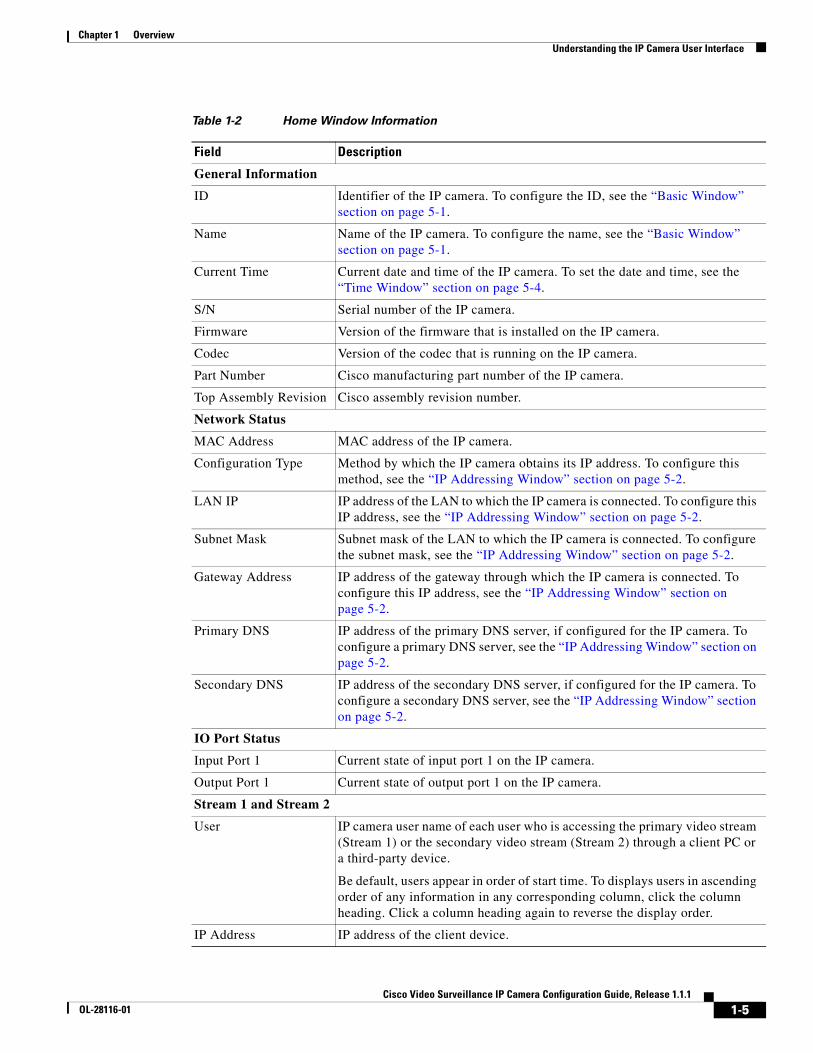
Table 1-2 Home Window Information
Field Description
General Information
ID Identifier of the IP camera. To configure the ID, see the “Basic Window” section on page 5-1.
Name Name of the IP camera. To configure the name, see the “Basic Window” section on page 5-1.
Current Time Current date and time of the IP camera. To set the date and time, see the “Time Window” section on page 5-4.
S/N Serial number of the IP camera.
Firmware Version of the firmware that is installed on the IP camera.
Codec Version of the codec that is running on the IP camera.
Part Number Cisco manufacturing part number of the IP camera.
Top Assembly Revision Cisco assembly revision number.
Network Status
MAC Address MAC address of the IP camera.
Configuration Type Method by which the IP camera obtains its IP address. To configure this method, see the “IP Addressing Window” section on page 5-2.
LAN IP IP address of the LAN to which the IP camera is connected. To configure this IP address, see the “IP Addressing Window” section on page 5-2.
Subnet Mask Subnet mask of the LAN to which the IP camera is connected. To configure the subnet mask, see the “IP Addressing Window” section on page 5-2.
Gateway Address IP address of the gateway through which the IP camera is connected. To configure this IP address, see the “IP Addressing Window” section on page 5-2.
Primary DNS IP address of the primary DNS server, if configured for the IP camera. To configure a primary DNS server, see the “IP Addressing Window” section on page 5-2.
Secondary DNS IP address of the secondary DNS server, if configured for the IP camera. To configure a secondary DNS server, see the “IP Addressing Window” section on page 5-2.
IO Port Status
Input Port 1 Current state of input port 1 on the IP camera.
Output Port 1 Current state of output port 1 on the IP camera.
Stream 1 and Stream 2
User IP camera user name of each user who is accessing the primary video stream (Stream 1) or the secondary video stream (Stream 2) through a client PC or a third-party device.
Be default, users appear in order of start time. To displays users in ascending order of any information in any corresponding column, click the column heading. Click a column heading again to reverse the display order.
IP Address IP address of the client device.
1-5Cisco Video Surveillance IP Camera Configuration Guide, Release 1.1.1
OL-28116-01

Chapter 1 OverviewUnderstanding the IP Camera User Interface
Start Time Time and date that the client accessed the video stream for this session.
Elapsed Time Length of time that the client has been accessing the video stream.
Table 1-2 Home Window Information (continued)
Field Description
1-6Cisco Video Surveillance IP Camera Configuration Guide, Release 1.1.1
OL-28116-01
Cisco Video SurveilOL-28116-01
C H A P T E R 2
Performing the Initial Setup of the IP CameraAfter you install the IP camera, or after you perform a factory reset procedure, you must access the IP camera and make initial configuration settings. These settings include administrator and root passwords, and whether the IP camera can be accessed through an HTTP connection in addition to the default HTTPS (HTTP secure) connection.
To make these configuration settings, you connect to the IP camera from any PC that is on the same network as the IP camera. The PC must meet these requirements:
• Operating system—Microsoft Windows 7 Enterprise (32-bit or 64-bit)
• Browser—Internet Explorer 8.0 (32-bit only)
In addition, you must know the IP address and default login credentials of the IP camera. By default, when the IP camera powers on, it attempts to obtain an IP address from a DHCP server in your network. If the camera cannot obtain an IP address through DCHP within 90 seconds, it uses a default IP address of 192.168.0.100. The default login credentials (Username/Password) are admin/admin.
To connect to the IP camera for the first time and make initial configuration settings, perform the following steps. You can change these configuration settings in the future as described in the Cisco Video Surveillance 6000 Series IP Camera Configuration Guide.
Before you Begin
The Microsoft .NET Framework version 2.0 or later must be installed on the PC that you use to connect to the IP camera. You can download the .NET Framework from the Microsoft website.
Procedure
Step 1 Start Internet Explorer, enter HTTPS://ip_address in the address field, and press Enter.
Replace ip_address with the IP address that the IP camera obtained through DHCP or, if the camera was unable to obtain this IP address, enter 192.168.0.100.
The Login window appears.
Step 2 Enter the default login credentials:
Username: admin
Password: admin
The Initialization window appears.
2-1lance IP Camera Configuration Guide, Release 1.1.1
Chapter 2 Performing the Initial Setup of the IP Camera
Step 3 In the Password and Confirm Password fields of the admin row, enter a password for the IP camera administrator.
You must enter the same password in both fields. The password is case sensitive and must contain at least eight characters, which can be letters, numbers, and special characters, but no spaces. Special characters are: ! " # $ % & ' ( ) * + , - . : ; < = > ? @ [ \ ] ^ _ ` { | } ~.
Step 4 In the Password and Confirm Password fields of the Root row, enter a password that is used when accessing the IP camera through a Secure Shell (SSH) connection.
You must enter the same password in both fields. The password is case sensitive and must contain at least eight characters, which can be letters, numbers, and special characters, but no spaces. Special characters are: ! " # $ % & ' ( ) * + , - . : ; < = > ? @ [ \ ] ^ _ ` { | } ~.
You use the root password if you need to troubleshoot the IP camera through a SSH connection with the assistance of the Cisco Technical Assistance Center.
Step 5 In the Access Protocols area, check the Enable HTTP check box if you want to allow both HTTP and HTTPS connections to the IP camera.
By default, only the Enable HTTPS check box is checked, which allows only HTTPS (secure) connections to the IP camera.
Step 6 Click Apply.
The IP camera reboots and the Login window appears.
Step 7 After the IP camera reboots, start Internet Explorer and, in the Address field, enter the following:
protocol://ip_address
where:
• protocol is HTTPS or HTTP. (You can use HTTP only if you enabled it in Step 5.)
• ip_address is the IP address that you used in Step 1.
Step 8 If you are prompted to install ActiveX controls, which are required to view video from the IP camera, follow the on-screen prompts to do so.
The Home window appears.
2-2Cisco Video Surveillance IP Camera Configuration Guide, Release 1.1.1
OL-28116-01
Cisco Video SurveilOL-28116-01
C H A P T E R 3
Viewing Live VideoAfter you install and set up the Cisco Video Surveillance IP Camera, can connect to the IP camera through Internet Explorer and access the Camera Video & Control window to view live video from the IP camera.
The Camera Video & Control window also provides for controlling the video display, configuring preset positions, and controlling certain IP camera functions. Available controls depend on the privilege level of the user.
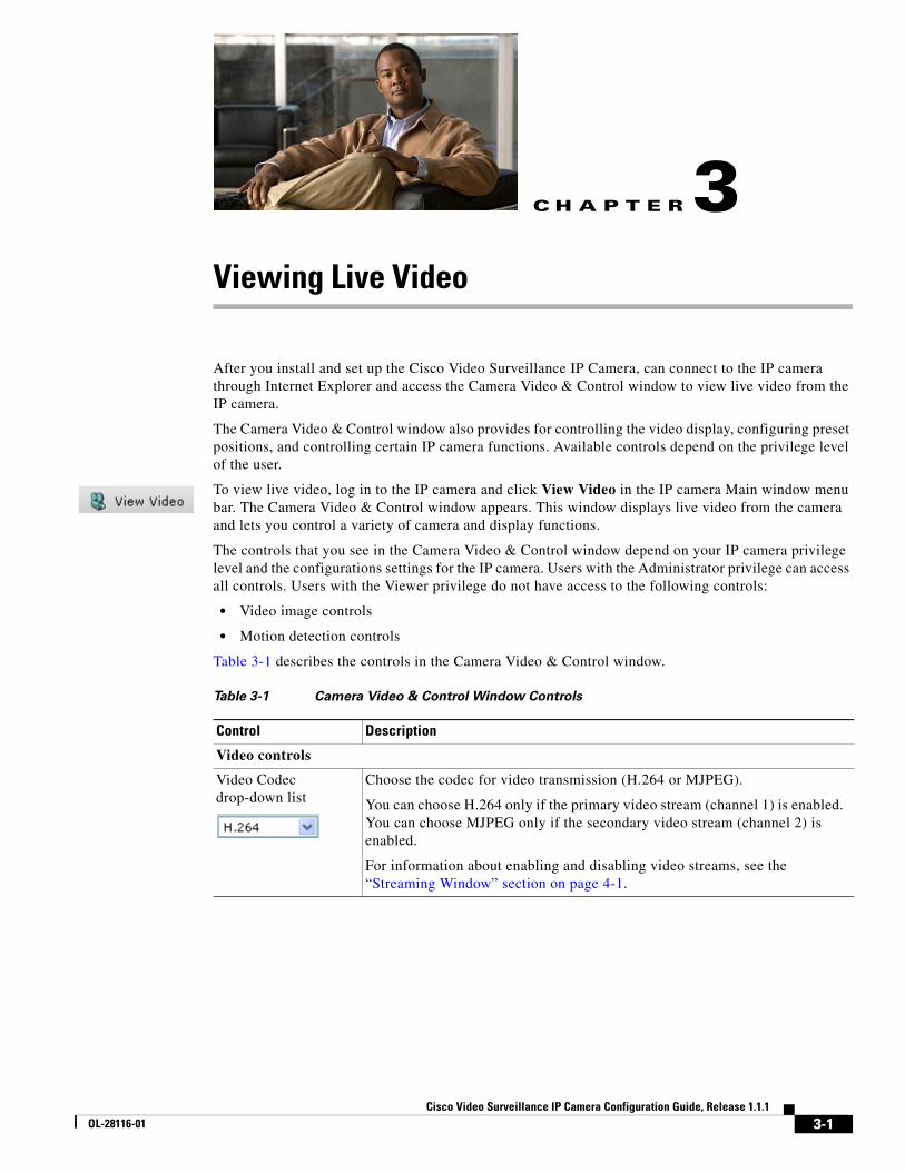
To view live video, log in to the IP camera and click View Video in the IP camera Main window menu bar. The Camera Video & Control window appears. This window displays live video from the camera and lets you control a variety of camera and display functions.
The controls that you see in the Camera Video & Control window depend on your IP camera privilege level and the configurations settings for the IP camera. Users with the Administrator privilege can access all controls. Users with the Viewer privilege do not have access to the following controls:
• Video image controls
• Motion detection controls
Table 3-1 describes the controls in the Camera Video & Control window.
Table 3-1 Camera Video & Control Window Controls
Control Description
Video controls
Video Codec drop-down list
Choose the codec for video transmission (H.264 or MJPEG).
You can choose H.264 only if the primary video stream (channel 1) is enabled. You can choose MJPEG only if the secondary video stream (channel 2) is enabled.
For information about enabling and disabling video streams, see the “Streaming Window” section on page 4-1.
3-1lance IP Camera Configuration Guide, Release 1.1.1
Chapter 3 Viewing Live Video
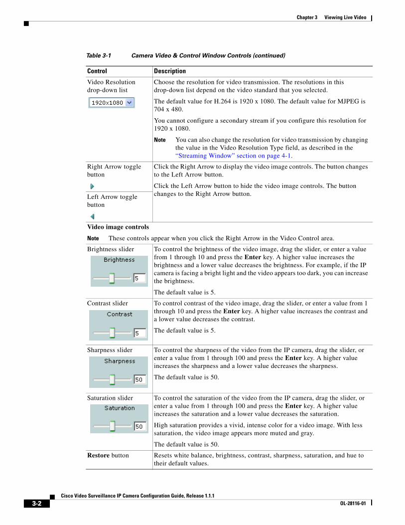
Video Resolution drop-down list
Choose the resolution for video transmission. The resolutions in this drop-down list depend on the video standard that you selected.
The default value for H.264 is 1920 x 1080. The default value for MJPEG is 704 x 480.
You cannot configure a secondary stream if you configure this resolution for 1920 x 1080.
Note You can also change the resolution for video transmission by changing the value in the Video Resolution Type field, as described in the “Streaming Window” section on page 4-1.
Right Arrow toggle button
Click the Right Arrow to display the video image controls. The button changes to the Left Arrow button.
Click the Left Arrow button to hide the video image controls. The button changes to the Right Arrow button.Left Arrow toggle
button
Video image controls
Note These controls appear when you click the Right Arrow in the Video Control area.
Brightness slider To control the brightness of the video image, drag the slider, or enter a value from 1 through 10 and press the Enter key. A higher value increases the brightness and a lower value decreases the brightness. For example, if the IP camera is facing a bright light and the video appears too dark, you can increase the brightness.
The default value is 5.
Contrast slider To control contrast of the video image, drag the slider, or enter a value from 1 through 10 and press the Enter key. A higher value increases the contrast and a lower value decreases the contrast.
The default value is 5.
Sharpness slider To control the sharpness of the video from the IP camera, drag the slider, or enter a value from 1 through 100 and press the Enter key. A higher value increases the sharpness and a lower value decreases the sharpness.
The default value is 50.
Saturation slider To control the saturation of the video from the IP camera, drag the slider, or enter a value from 1 through 100 and press the Enter key. A higher value increases the saturation and a lower value decreases the saturation.
High saturation provides a vivid, intense color for a video image. With less saturation, the video image appears more muted and gray.
The default value is 50.
Restore button Resets white balance, brightness, contrast, sharpness, saturation, and hue to their default values.
Table 3-1 Camera Video & Control Window Controls (continued)
Control Description
3-2Cisco Video Surveillance IP Camera Configuration Guide, Release 1.1.1
OL-28116-01

Chapter 3 Viewing Live Video
Image tools
Hotspot Zoom button Click this latch button to enables the digital zoom feature, which provides five-step digital zooming in for the normal (not full screen) video display. Click this button again to disable the digital zoom feature.
To perform a digital zoom, engage the Hotspot Zoom button and click the video display. The first five clicks zoom the display. The sixth click returns to unzoomed display.
Hotspot Pan/Tilt button
Click this latch button to enable the hotspot pan/tilt feature, which lets you pan and tilt the IP camera toward a point that you click in the video display.
To perform a hotspot pan/tilt action, engage the Hotspot Pan/Tilt button, then click the video image at the location toward which you want the IP camera to pan and tilt.
This feature require that the IP camera be installed with a pan/tilt mount that supports the Pelco D protocol and that pan and tilt functions are enabled.
Save Snapshot button Captures and saves a the current video image as a .gif file or a .jpg file in the location of your choice and with the file name of your choice.
When you click this button, the Snapshot window appears. Click Save and follow the on-screen prompts to save the image with the name and in the location that you want.
Flip button Rotates the video image by 180 degrees.
Mirror button Reverses the video image.
Restore button Displays the default video image, which is not rotated and not reversed.
Full Screen button Displays the video image in full screen mode.
To return to normal display mode, click the full screen image.
Motion detection
Up Arrow toggle button
Click the Up Arrow to display the motion detection controls. The button changes to the Down Arrow button.
Click the Down Arrow button to hide the motion detection controls. The button changes to the Up Arrow button.Down Arrow toggle
button
Table 3-1 Camera Video & Control Window Controls (continued)
Control Description
3-3Cisco Video Surveillance IP Camera Configuration Guide, Release 1.1.1
OL-28116-01
Chapter 3 Viewing Live Video
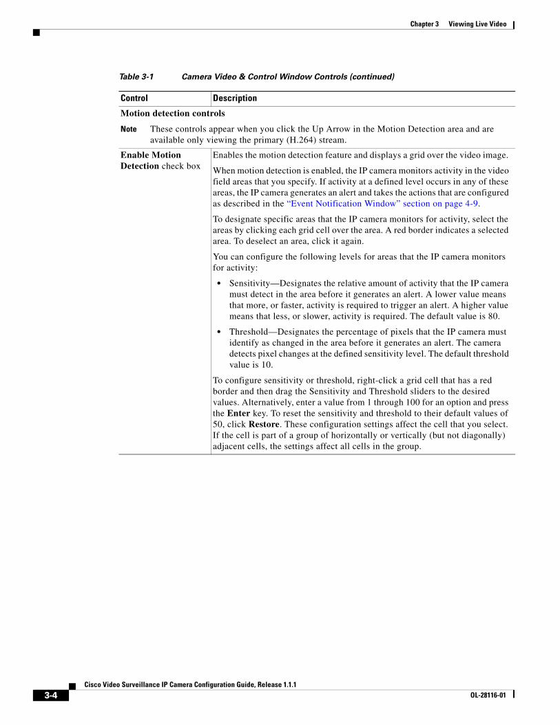
Motion detection controls
Note These controls appear when you click the Up Arrow in the Motion Detection area and are available only viewing the primary (H.264) stream.
Enable Motion Detection check box
Enables the motion detection feature and displays a grid over the video image.
When motion detection is enabled, the IP camera monitors activity in the video field areas that you specify. If activity at a defined level occurs in any of these areas, the IP camera generates an alert and takes the actions that are configured as described in the “Event Notification Window” section on page 4-9.
To designate specific areas that the IP camera monitors for activity, select the areas by clicking each grid cell over the area. A red border indicates a selected area. To deselect an area, click it again.
You can configure the following levels for areas that the IP camera monitors for activity:
• Sensitivity—Designates the relative amount of activity that the IP camera must detect in the area before it generates an alert. A lower value means that more, or faster, activity is required to trigger an alert. A higher value means that less, or slower, activity is required. The default value is 80.
• Threshold—Designates the percentage of pixels that the IP camera must identify as changed in the area before it generates an alert. The camera detects pixel changes at the defined sensitivity level. The default threshold value is 10.
To configure sensitivity or threshold, right-click a grid cell that has a red border and then drag the Sensitivity and Threshold sliders to the desired values. Alternatively, enter a value from 1 through 100 for an option and press the Enter key. To reset the sensitivity and threshold to their default values of 50, click Restore. These configuration settings affect the cell that you select. If the cell is part of a group of horizontally or vertically (but not diagonally) adjacent cells, the settings affect all cells in the group.
Table 3-1 Camera Video & Control Window Controls (continued)
Control Description
3-4Cisco Video Surveillance IP Camera Configuration Guide, Release 1.1.1
OL-28116-01
Chapter 3 Viewing Live Video
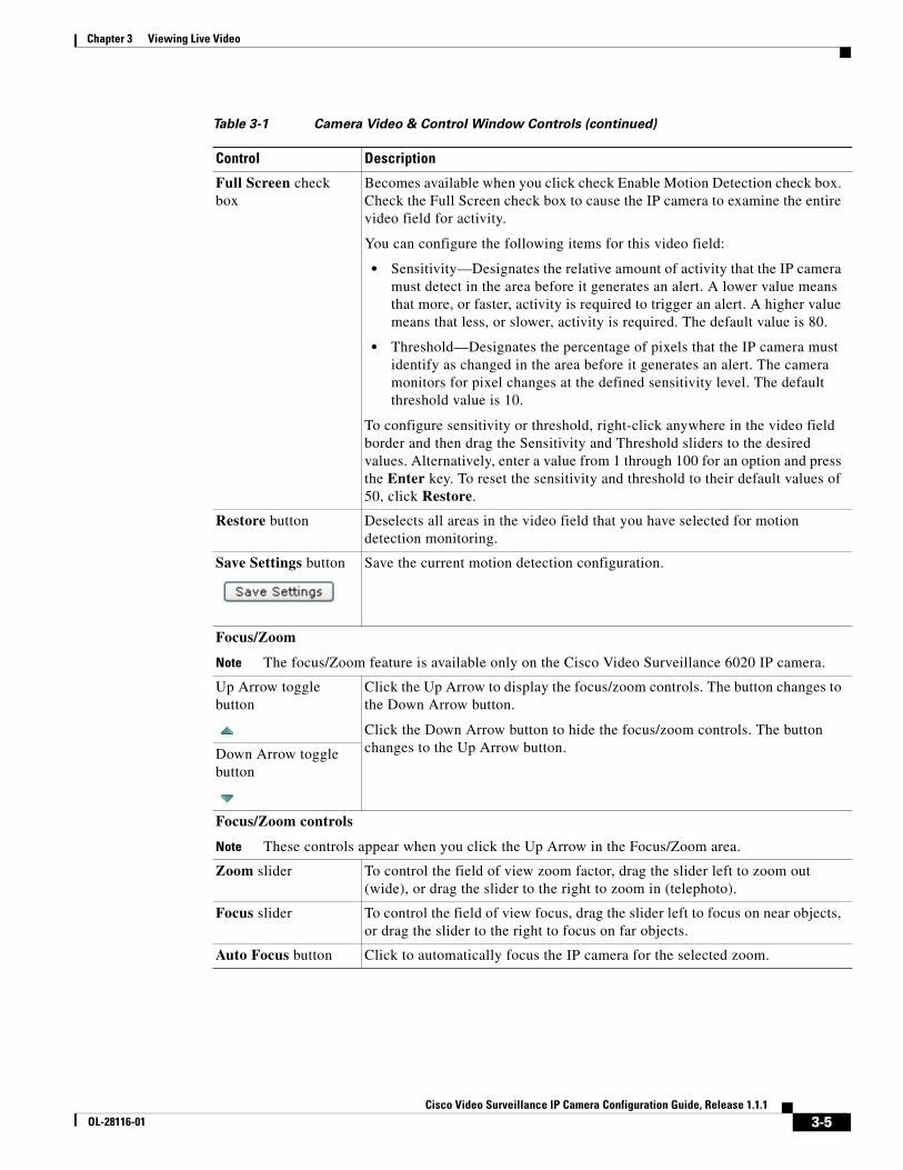
Full Screen check box
Becomes available when you click check Enable Motion Detection check box. Check the Full Screen check box to cause the IP camera to examine the entire video field for activity.
You can configure the following items for this video field:
• Sensitivity—Designates the relative amount of activity that the IP camera must detect in the area before it generates an alert. A lower value means that more, or faster, activity is required to trigger an alert. A higher value means that less, or slower, activity is required. The default value is 80.
• Threshold—Designates the percentage of pixels that the IP camera must identify as changed in the area before it generates an alert. The camera monitors for pixel changes at the defined sensitivity level. The default threshold value is 10.
To configure sensitivity or threshold, right-click anywhere in the video field border and then drag the Sensitivity and Threshold sliders to the desired values. Alternatively, enter a value from 1 through 100 for an option and press the Enter key. To reset the sensitivity and threshold to their default values of 50, click Restore.
Restore button Deselects all areas in the video field that you have selected for motion detection monitoring.
Save Settings button Save the current motion detection configuration.
Focus/Zoom
Note The focus/Zoom feature is available only on the Cisco Video Surveillance 6020 IP camera.
Up Arrow toggle button
Click the Up Arrow to display the focus/zoom controls. The button changes to the Down Arrow button.
Click the Down Arrow button to hide the focus/zoom controls. The button changes to the Up Arrow button.Down Arrow toggle
button
Focus/Zoom controls
Note These controls appear when you click the Up Arrow in the Focus/Zoom area.
Zoom slider To control the field of view zoom factor, drag the slider left to zoom out (wide), or drag the slider to the right to zoom in (telephoto).
Focus slider To control the field of view focus, drag the slider left to focus on near objects, or drag the slider to the right to focus on far objects.
Auto Focus button Click to automatically focus the IP camera for the selected zoom.
Table 3-1 Camera Video & Control Window Controls (continued)
Control Description
3-5Cisco Video Surveillance IP Camera Configuration Guide, Release 1.1.1
OL-28116-01
Chapter 3 Viewing Live Video
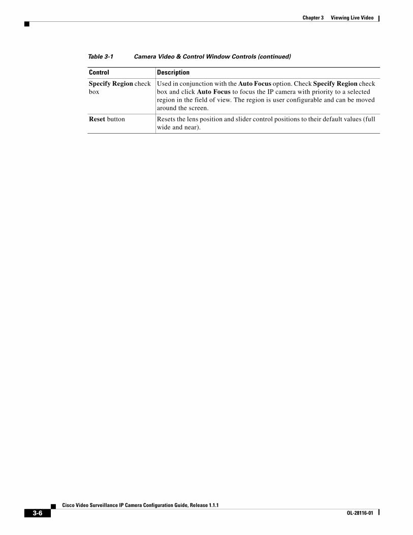
Specify Region check box
Used in conjunction with the Auto Focus option. Check Specify Region check box and click Auto Focus to focus the IP camera with priority to a selected region in the field of view. The region is user configurable and can be moved around the screen.
Reset button Resets the lens position and slider control positions to their default values (full wide and near).
Table 3-1 Camera Video & Control Window Controls (continued)
Control Description
3-6Cisco Video Surveillance IP Camera Configuration Guide, Release 1.1.1
OL-28116-01
Cisco Video SurveilOL-28116-01
C H A P T E R 4
Feature SetupThe Feature Setup windows let you configure a variety of IP camera features and functions. The following sections describe the Feature Setup windows in detail:
• Streaming Window, page 4-1
• Camera Window, page 4-5
• Video Overlay Window, page 4-7
• IO Ports Window, page 4-8
• Event Notification Window, page 4-9
Streaming WindowThe Streaming window provides options for configuring video streams from the IP camera. You can configure settings for the primary and an optional secondary video stream.
Configuring a secondary stream is useful for providing a video stream that is at a lower resolution than the primary stream to third-party devices or software.
The primary stream supports H.264 for video. The secondary stream supports MJPEG for video.
When configuring video streams, be aware of the following guidelines:
• You cannot configure a secondary stream (channel 2) if you configure the resolution for the primary stream (channel 1) to 1920 x 1080
• You cannot configure the resolution for the primary stream to 1920 x 1080 if a secondary stream is enabled
• The resolution of the primary stream must be higher than the resolution of the secondary stream
• You cannot configure a maximum frame rate of 30 for the primary stream if the secondary stream is enabled.
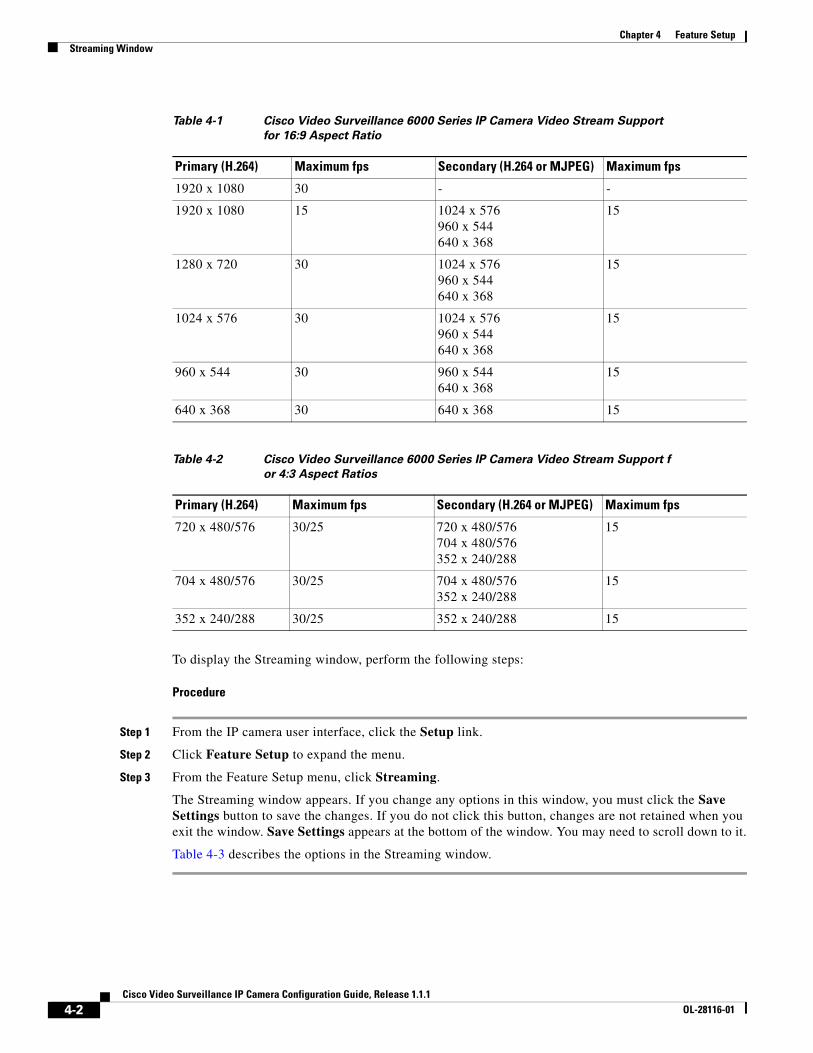
• Multiple secondary frame rates are supported. Table 4-1 shows the frame rate combinations of primary and secondary streams with a 16:9 aspect ratio, and Table 4-2 shows the frame rate combinations of primary and secondary streams with a 4:3 aspect ratio. If a secondary frame rate that is not shown in this table is selected in Cisco Video Surveillance Manager, the IP camera uses the closest available frame rate.
4-1lance IP Camera Configuration Guide, Release 1.1.1
Chapter 4 Feature SetupStreaming Window
To display the Streaming window, perform the following steps:
Procedure
Step 1 From the IP camera user interface, click the Setup link.
Step 2 Click Feature Setup to expand the menu.
Step 3 From the Feature Setup menu, click Streaming.
The Streaming window appears. If you change any options in this window, you must click the Save Settings button to save the changes. If you do not click this button, changes are not retained when you exit the window. Save Settings appears at the bottom of the window. You may need to scroll down to it.
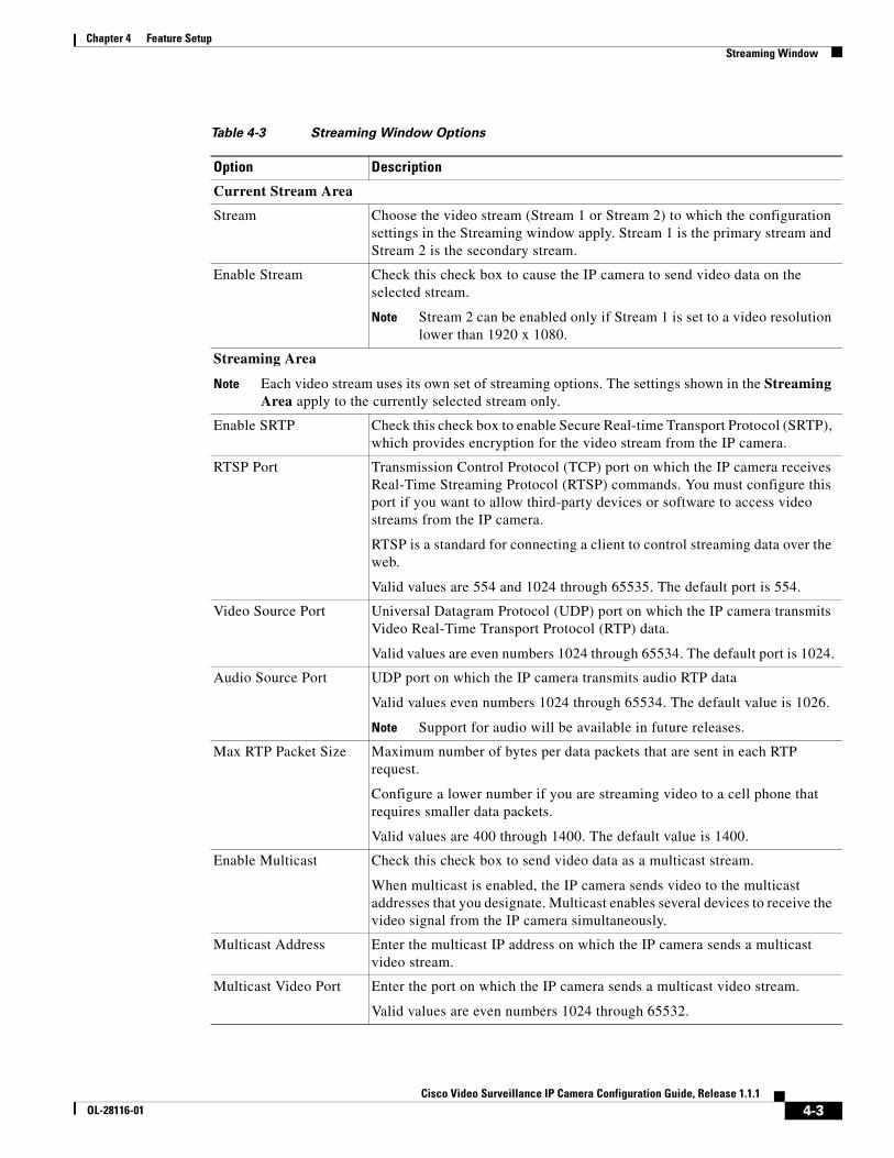
Table 4-3 describes the options in the Streaming window.
Table 4-1 Cisco Video Surveillance 6000 Series IP Camera Video Stream Support for 16:9 Aspect Ratio
Primary (H.264) Maximum fps Secondary (H.264 or MJPEG) Maximum fps
1920 x 1080 30 - -
1920 x 1080 15 1024 x 576 960 x 544 640 x 368
15
1280 x 720 30 1024 x 576 960 x 544 640 x 368
15
1024 x 576 30 1024 x 576 960 x 544 640 x 368
15
960 x 544 30 960 x 544 640 x 368
15
640 x 368 30 640 x 368 15
Table 4-2 Cisco Video Surveillance 6000 Series IP Camera Video Stream Support f or 4:3 Aspect Ratios
Primary (H.264) Maximum fps Secondary (H.264 or MJPEG) Maximum fps
720 x 480/576 30/25 720 x 480/576 704 x 480/576 352 x 240/288
15
704 x 480/576 30/25 704 x 480/576 352 x 240/288
15
352 x 240/288 30/25 352 x 240/288 15
4-2Cisco Video Surveillance IP Camera Configuration Guide, Release 1.1.1
OL-28116-01
Chapter 4 Feature SetupStreaming Window
Table 4-3 Streaming Window Options
Option Description
Current Stream Area
Stream Choose the video stream (Stream 1 or Stream 2) to which the configuration settings in the Streaming window apply. Stream 1 is the primary stream and Stream 2 is the secondary stream.
Enable Stream Check this check box to cause the IP camera to send video data on the selected stream.
Note Stream 2 can be enabled only if Stream 1 is set to a video resolution lower than 1920 x 1080.
Streaming Area
Note Each video stream uses its own set of streaming options. The settings shown in the Streaming Area apply to the currently selected stream only.
Enable SRTP Check this check box to enable Secure Real-time Transport Protocol (SRTP), which provides encryption for the video stream from the IP camera.
RTSP Port Transmission Control Protocol (TCP) port on which the IP camera receives Real-Time Streaming Protocol (RTSP) commands. You must configure this port if you want to allow third-party devices or software to access video streams from the IP camera.
RTSP is a standard for connecting a client to control streaming data over the web.
Valid values are 554 and 1024 through 65535. The default port is 554.
Video Source Port Universal Datagram Protocol (UDP) port on which the IP camera transmits Video Real-Time Transport Protocol (RTP) data.
Valid values are even numbers 1024 through 65534. The default port is 1024.
Audio Source Port UDP port on which the IP camera transmits audio RTP data
Valid values even numbers 1024 through 65534. The default value is 1026.
Note Support for audio will be available in future releases.
Max RTP Packet Size Maximum number of bytes per data packets that are sent in each RTP request.
Configure a lower number if you are streaming video to a cell phone that requires smaller data packets.
Valid values are 400 through 1400. The default value is 1400.
Enable Multicast Check this check box to send video data as a multicast stream.
When multicast is enabled, the IP camera sends video to the multicast addresses that you designate. Multicast enables several devices to receive the video signal from the IP camera simultaneously.
Multicast Address Enter the multicast IP address on which the IP camera sends a multicast video stream.
Multicast Video Port Enter the port on which the IP camera sends a multicast video stream.
Valid values are even numbers 1024 through 65532.
4-3Cisco Video Surveillance IP Camera Configuration Guide, Release 1.1.1
OL-28116-01
Chapter 4 Feature SetupStreaming Window
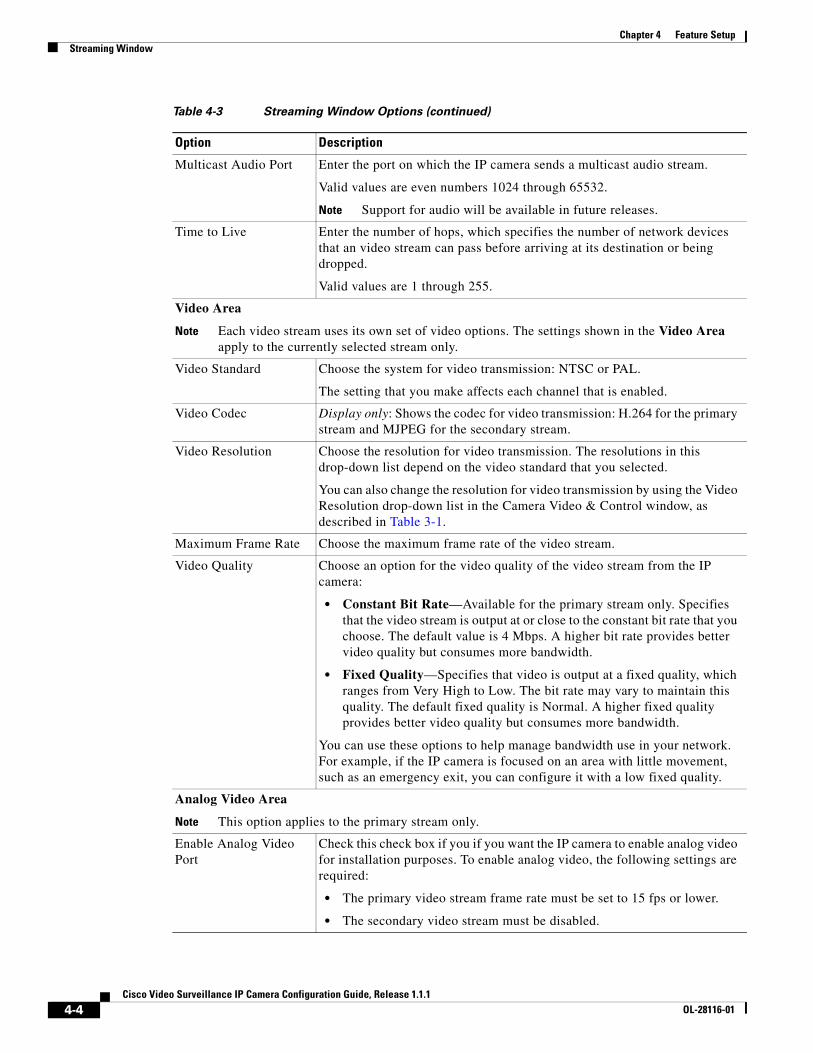
Multicast Audio Port Enter the port on which the IP camera sends a multicast audio stream.
Valid values are even numbers 1024 through 65532.
Note Support for audio will be available in future releases.
Time to Live Enter the number of hops, which specifies the number of network devices that an video stream can pass before arriving at its destination or being dropped.
Valid values are 1 through 255.
Video Area
Note Each video stream uses its own set of video options. The settings shown in the Video Area apply to the currently selected stream only.
Video Standard Choose the system for video transmission: NTSC or PAL.
The setting that you make affects each channel that is enabled.
Video Codec Display only: Shows the codec for video transmission: H.264 for the primary stream and MJPEG for the secondary stream.
Video Resolution Choose the resolution for video transmission. The resolutions in this drop-down list depend on the video standard that you selected.
You can also change the resolution for video transmission by using the Video Resolution drop-down list in the Camera Video & Control window, as described in Table 3-1.
Maximum Frame Rate Choose the maximum frame rate of the video stream.
Video Quality Choose an option for the video quality of the video stream from the IP camera:
• Constant Bit Rate—Available for the primary stream only. Specifies that the video stream is output at or close to the constant bit rate that you choose. The default value is 4 Mbps. A higher bit rate provides better video quality but consumes more bandwidth.
• Fixed Quality—Specifies that video is output at a fixed quality, which ranges from Very High to Low. The bit rate may vary to maintain this quality. The default fixed quality is Normal. A higher fixed quality provides better video quality but consumes more bandwidth.
You can use these options to help manage bandwidth use in your network. For example, if the IP camera is focused on an area with little movement, such as an emergency exit, you can configure it with a low fixed quality.
Analog Video Area
Note This option applies to the primary stream only.
Enable Analog Video Port
Check this check box if you if you want the IP camera to enable analog video for installation purposes. To enable analog video, the following settings are required:
• The primary video stream frame rate must be set to 15 fps or lower.
• The secondary video stream must be disabled.
Table 4-3 Streaming Window Options (continued)
Option Description
4-4Cisco Video Surveillance IP Camera Configuration Guide, Release 1.1.1
OL-28116-01
Chapter 4 Feature SetupCamera Window
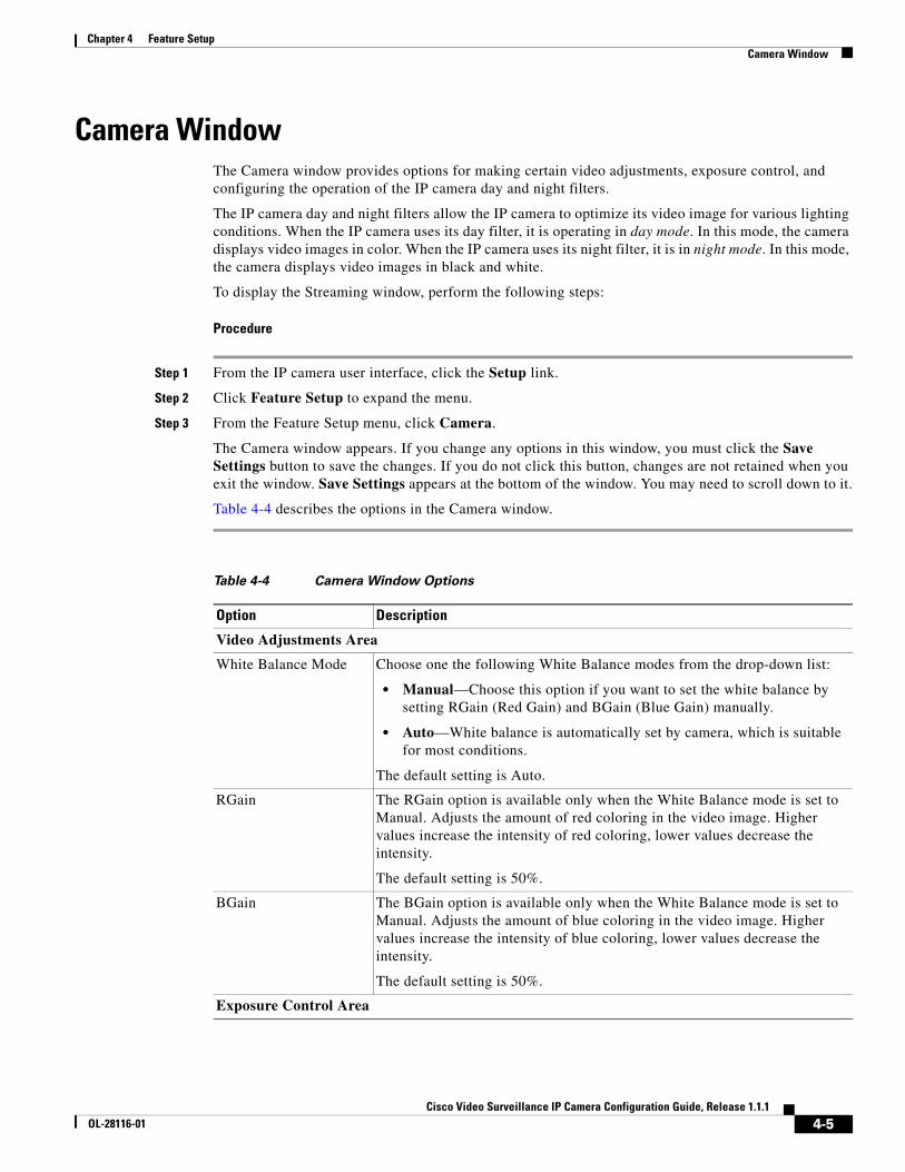
Camera WindowThe Camera window provides options for making certain video adjustments, exposure control, and configuring the operation of the IP camera day and night filters.
The IP camera day and night filters allow the IP camera to optimize its video image for various lighting conditions. When the IP camera uses its day filter, it is operating in day mode. In this mode, the camera displays video images in color. When the IP camera uses its night filter, it is in night mode. In this mode, the camera displays video images in black and white.
To display the Streaming window, perform the following steps:
Procedure
Step 1 From the IP camera user interface, click the Setup link.
Step 2 Click Feature Setup to expand the menu.
Step 3 From the Feature Setup menu, click Camera.
The Camera window appears. If you change any options in this window, you must click the Save Settings button to save the changes. If you do not click this button, changes are not retained when you exit the window. Save Settings appears at the bottom of the window. You may need to scroll down to it.
Table 4-4 describes the options in the Camera window.
Table 4-4 Camera Window Options
Option Description
Video Adjustments Area
White Balance Mode Choose one the following White Balance modes from the drop-down list:
• Manual—Choose this option if you want to set the white balance by setting RGain (Red Gain) and BGain (Blue Gain) manually.
• Auto—White balance is automatically set by camera, which is suitable for most conditions.
The default setting is Auto.
RGain The RGain option is available only when the White Balance mode is set to Manual. Adjusts the amount of red coloring in the video image. Higher values increase the intensity of red coloring, lower values decrease the intensity.
The default setting is 50%.
BGain The BGain option is available only when the White Balance mode is set to Manual. Adjusts the amount of blue coloring in the video image. Higher values increase the intensity of blue coloring, lower values decrease the intensity.
The default setting is 50%.
Exposure Control Area
4-5Cisco Video Surveillance IP Camera Configuration Guide, Release 1.1.1
OL-28116-01
Chapter 4 Feature SetupCamera Window
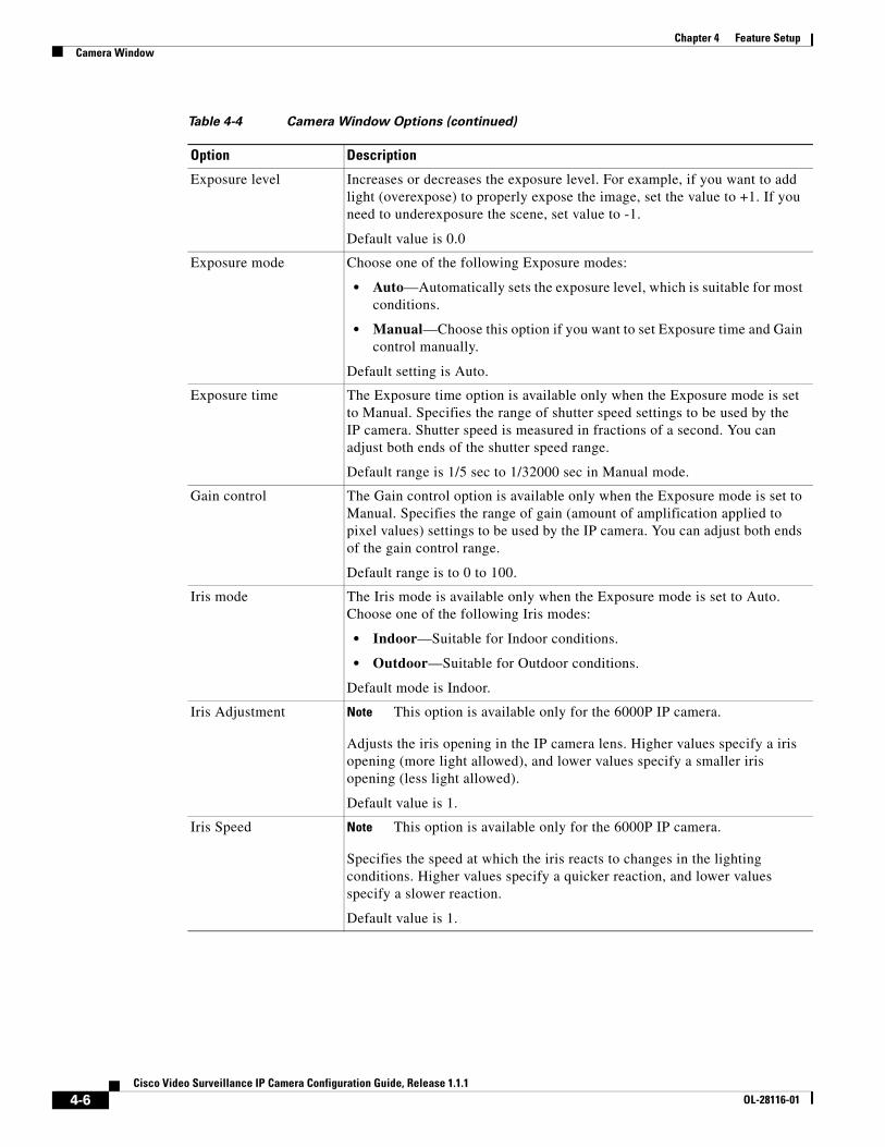
Exposure level Increases or decreases the exposure level. For example, if you want to add light (overexpose) to properly expose the image, set the value to +1. If you need to underexposure the scene, set value to -1.
Default value is 0.0
Exposure mode Choose one of the following Exposure modes:
• Auto—Automatically sets the exposure level, which is suitable for most conditions.
• Manual—Choose this option if you want to set Exposure time and Gain control manually.
Default setting is Auto.
Exposure time The Exposure time option is available only when the Exposure mode is set to Manual. Specifies the range of shutter speed settings to be used by the IP camera. Shutter speed is measured in fractions of a second. You can adjust both ends of the shutter speed range.
Default range is 1/5 sec to 1/32000 sec in Manual mode.
Gain control The Gain control option is available only when the Exposure mode is set to Manual. Specifies the range of gain (amount of amplification applied to pixel values) settings to be used by the IP camera. You can adjust both ends of the gain control range.
Default range is to 0 to 100.
Iris mode The Iris mode is available only when the Exposure mode is set to Auto. Choose one of the following Iris modes:
• Indoor—Suitable for Indoor conditions.
• Outdoor—Suitable for Outdoor conditions.
Default mode is Indoor.
Iris Adjustment Note This option is available only for the 6000P IP camera.
Adjusts the iris opening in the IP camera lens. Higher values specify a iris opening (more light allowed), and lower values specify a smaller iris opening (less light allowed).
Default value is 1.
Iris Speed Note This option is available only for the 6000P IP camera.
Specifies the speed at which the iris reacts to changes in the lighting conditions. Higher values specify a quicker reaction, and lower values specify a slower reaction.
Default value is 1.
Table 4-4 Camera Window Options (continued)
Option Description
4-6Cisco Video Surveillance IP Camera Configuration Guide, Release 1.1.1
OL-28116-01
Chapter 4 Feature SetupVideo Overlay Window
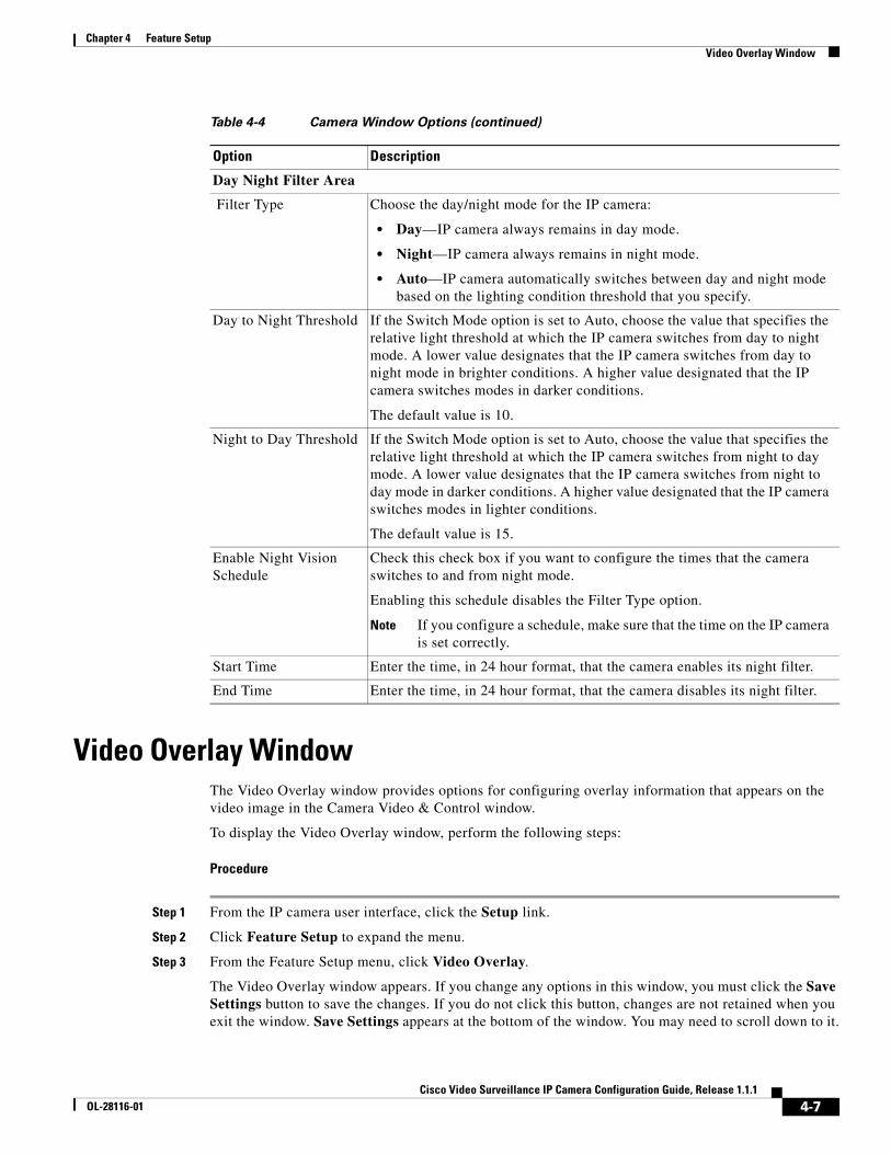
Video Overlay WindowThe Video Overlay window provides options for configuring overlay information that appears on the video image in the Camera Video & Control window.
To display the Video Overlay window, perform the following steps:
Procedure
Step 1 From the IP camera user interface, click the Setup link.
Step 2 Click Feature Setup to expand the menu.
Step 3 From the Feature Setup menu, click Video Overlay.
The Video Overlay window appears. If you change any options in this window, you must click the Save Settings button to save the changes. If you do not click this button, changes are not retained when you exit the window. Save Settings appears at the bottom of the window. You may need to scroll down to it.
Day Night Filter Area
Filter Type Choose the day/night mode for the IP camera:
• Day—IP camera always remains in day mode.
• Night—IP camera always remains in night mode.
• Auto—IP camera automatically switches between day and night mode based on the lighting condition threshold that you specify.
Day to Night Threshold If the Switch Mode option is set to Auto, choose the value that specifies the relative light threshold at which the IP camera switches from day to night mode. A lower value designates that the IP camera switches from day to night mode in brighter conditions. A higher value designated that the IP camera switches modes in darker conditions.
The default value is 10.
Night to Day Threshold If the Switch Mode option is set to Auto, choose the value that specifies the relative light threshold at which the IP camera switches from night to day mode. A lower value designates that the IP camera switches from night to day mode in darker conditions. A higher value designated that the IP camera switches modes in lighter conditions.
The default value is 15.
Enable Night Vision Schedule
Check this check box if you want to configure the times that the camera switches to and from night mode.
Enabling this schedule disables the Filter Type option.
Note If you configure a schedule, make sure that the time on the IP camera is set correctly.
Start Time Enter the time, in 24 hour format, that the camera enables its night filter.
End Time Enter the time, in 24 hour format, that the camera disables its night filter.
Table 4-4 Camera Window Options (continued)
Option Description
4-7Cisco Video Surveillance IP Camera Configuration Guide, Release 1.1.1
OL-28116-01
Chapter 4 Feature SetupIO Ports Window
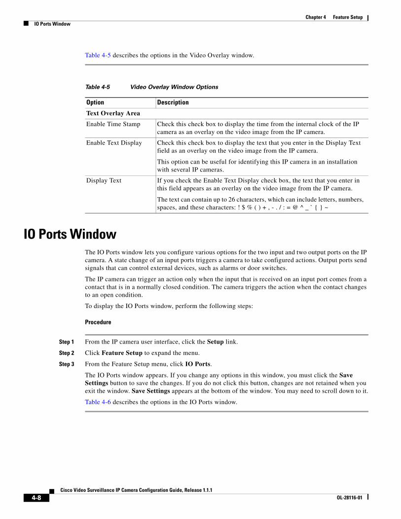
Table 4-5 describes the options in the Video Overlay window.
IO Ports WindowThe IO Ports window lets you configure various options for the two input and two output ports on the IP camera. A state change of an input ports triggers a camera to take configured actions. Output ports send signals that can control external devices, such as alarms or door switches.
The IP camera can trigger an action only when the input that is received on an input port comes from a contact that is in a normally closed condition. The camera triggers the action when the contact changes to an open condition.
To display the IO Ports window, perform the following steps:
Procedure
Step 1 From the IP camera user interface, click the Setup link.
Step 2 Click Feature Setup to expand the menu.
Step 3 From the Feature Setup menu, click IO Ports.
The IO Ports window appears. If you change any options in this window, you must click the Save Settings button to save the changes. If you do not click this button, changes are not retained when you exit the window. Save Settings appears at the bottom of the window. You may need to scroll down to it.
Table 4-6 describes the options in the IO Ports window.
Table 4-5 Video Overlay Window Options
Option Description
Text Overlay Area
Enable Time Stamp Check this check box to display the time from the internal clock of the IP camera as an overlay on the video image from the IP camera.
Enable Text Display Check this check box to display the text that you enter in the Display Text field as an overlay on the video image from the IP camera.
This option can be useful for identifying this IP camera in an installation with several IP cameras.
Display Text If you check the Enable Text Display check box, the text that you enter in this field appears as an overlay on the video image from the IP camera.
The text can contain up to 26 characters, which can include letters, numbers, spaces, and these characters: ! $ % ( ) + , - . / : = @ ^ _ ` { } ~
4-8Cisco Video Surveillance IP Camera Configuration Guide, Release 1.1.1
OL-28116-01
Chapter 4 Feature SetupEvent Notification Window
Event Notification WindowThe Event Notification window provides options for how the IP camera handles events. An event is any of the following:
• A change of state from low to high or from high to low on an input port of the IP camera. For related information about input ports, see the “IO Ports Window” section on page 4-8.
• Motion that the IP camera detects. For related information about motion detection, see the “Motion detection controls” rows in Table 3-1.
• Loss of video signal.
When an event occurs, it triggers the IP camera to take certain configured actions:
• HTTP notification—IP camera sends notification to a remote system via HTTP. This information includes the following:
– Device ID—ID of the IP camera
– Device name—Name of the IP camera
– IP address—IP address of the IP camera
– MAC address—MAC address of the IP camera
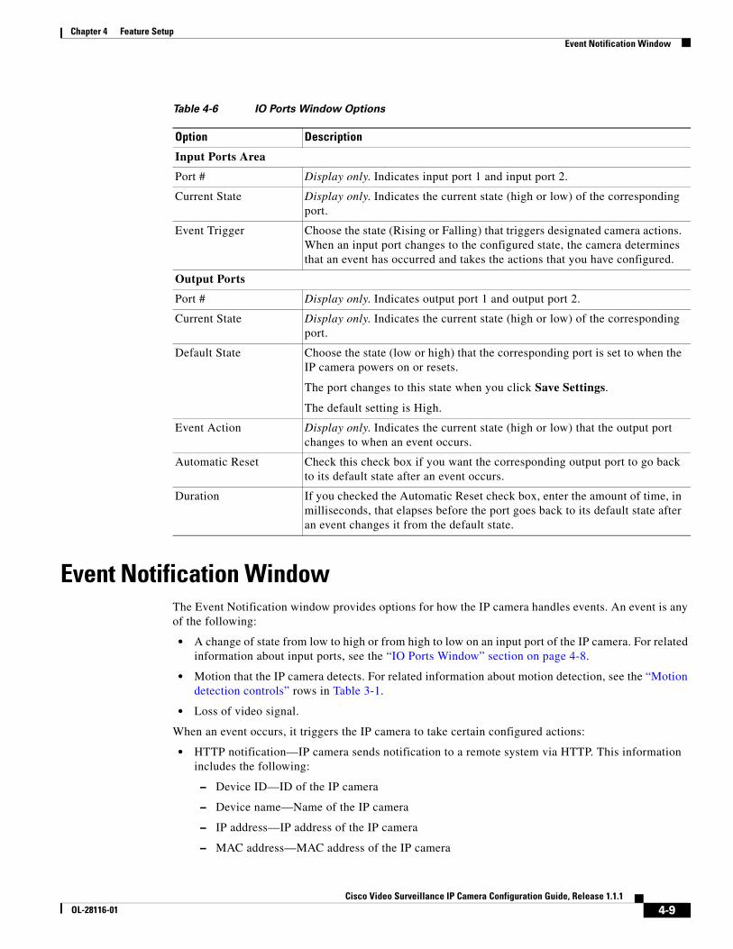
Table 4-6 IO Ports Window Options
Option Description
Input Ports Area
Port # Display only. Indicates input port 1 and input port 2.
Current State Display only. Indicates the current state (high or low) of the corresponding port.
Event Trigger Choose the state (Rising or Falling) that triggers designated camera actions. When an input port changes to the configured state, the camera determines that an event has occurred and takes the actions that you have configured.
Output Ports
Port # Display only. Indicates output port 1 and output port 2.
Current State Display only. Indicates the current state (high or low) of the corresponding port.
Default State Choose the state (low or high) that the corresponding port is set to when the IP camera powers on or resets.
The port changes to this state when you click Save Settings.
The default setting is High.
Event Action Display only. Indicates the current state (high or low) that the output port changes to when an event occurs.
Automatic Reset Check this check box if you want the corresponding output port to go back to its default state after an event occurs.
Duration If you checked the Automatic Reset check box, enter the amount of time, in milliseconds, that elapses before the port goes back to its default state after an event changes it from the default state.
4-9Cisco Video Surveillance IP Camera Configuration Guide, Release 1.1.1
OL-28116-01
Chapter 4 Feature SetupEvent Notification Window
– Channel ID—Channel identification number (1 for primary stream or 2 for secondary stream)
– Channel name—Name that is configured for the channel
– Date and time—Date and time that the event occurred
– Active post Count—Sequence number of the notification for this event
– Event type—Type of event
– Event state—Indicates whether the event is active or inactive at the time that the event was detected for this notification
– Event description—Description of the event.
– Input port ID—If the event was triggered by an input port state change, port ID of the port
– Region index—If the event was triggered by motion detection, identification number of the region in which the IP camera detected motion
– Sensitivity level—If the event was triggered by motion detection, sensitivity that is configured for the region in which motion was detected
– Detection threshold—If the event was triggered by motion detection, threshold that is configured for the region in which motion was detected
• Output port state change—Changes the state of an IP camera output port from low to high or from high to low.
• Syslog server message—Sends a notification message to the designated Syslog server.
The Event Notification window also allows you to designate schedules. If an event takes place within a designated schedule, the IP camera takes the actions that you configure.
Procedure
Step 1 From the IP camera user interface, click the Setup link.
Step 2 Click Feature Setup to expand the menu.
Step 3 From the Feature Setup menu, click Event.
The Event Notification window appears. If you change any options in this window, you must click the Save Settings button to save the changes. If you do not click this button, changes are not retained when you exit the window. Save Settings appears at the bottom of the window. You may need to scroll down to it.
Table 4-7 describes the options in the Event Notification window.
4-10Cisco Video Surveillance IP Camera Configuration Guide, Release 1.1.1
OL-28116-01
Chapter 4 Feature SetupEvent Notification Window
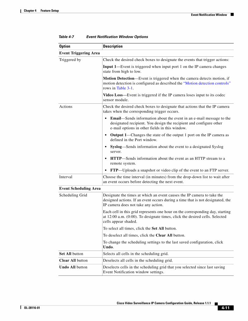
Table 4-7 Event Notification Window Options
Option Description
Event Triggering Area
Triggered by Check the desired check boxes to designate the events that trigger actions:
Input 1—Event is triggered when input port 1 on the IP camera changes state from high to low.
Motion Detection—Event is triggered when the camera detects motion, if motion detection is configured as described the “Motion detection controls” rows in Table 3-1.
Video Loss—Event is triggered if the IP camera loses input to its codec sensor module.
Actions Check the desired check boxes to designate that actions that the IP camera takes when the corresponding trigger occurs.
• Email—Sends information about the event in an e-mail message to the designated recipient. You design the recipient and configure other e-mail options in other fields in this window.
• Output 1—Changes the state of the output 1 port on the IP camera as defined in the Port window.
• Syslog—Sends information about the event to a designated Syslog server.
• HTTP—Sends information about the event as an HTTP stream to a remote system.
• FTP—Uploads a snapshot or video clip of the event to an FTP server.
Interval Choose the time interval (in minutes) from the drop-down list to wait after an event occurs before detecting the next event.
Event Scheduling Area
Scheduling Grid Designate the times at which an event causes the IP camera to take the designed actions. If an event occurs during a time that is not designated, the IP camera does not take any action.
Each cell in this grid represents one hour on the corresponding day, starting at 12:00 a.m. (0:00). To designate times, click the desired cells. Selected cells appear shaded.
To select all times, click the Set All button.
To deselect all times, click the Clear All button.
To change the scheduling settings to the last saved configuration, click Undo.
Set All button Selects all cells in the scheduling grid.
Clear All button Deselects all cells in the scheduling grid.
Undo All button Deselects cells in the scheduling grid that you selected since last saving Event Notification window settings.
4-11Cisco Video Surveillance IP Camera Configuration Guide, Release 1.1.1
OL-28116-01
Chapter 4 Feature SetupEvent Notification Window
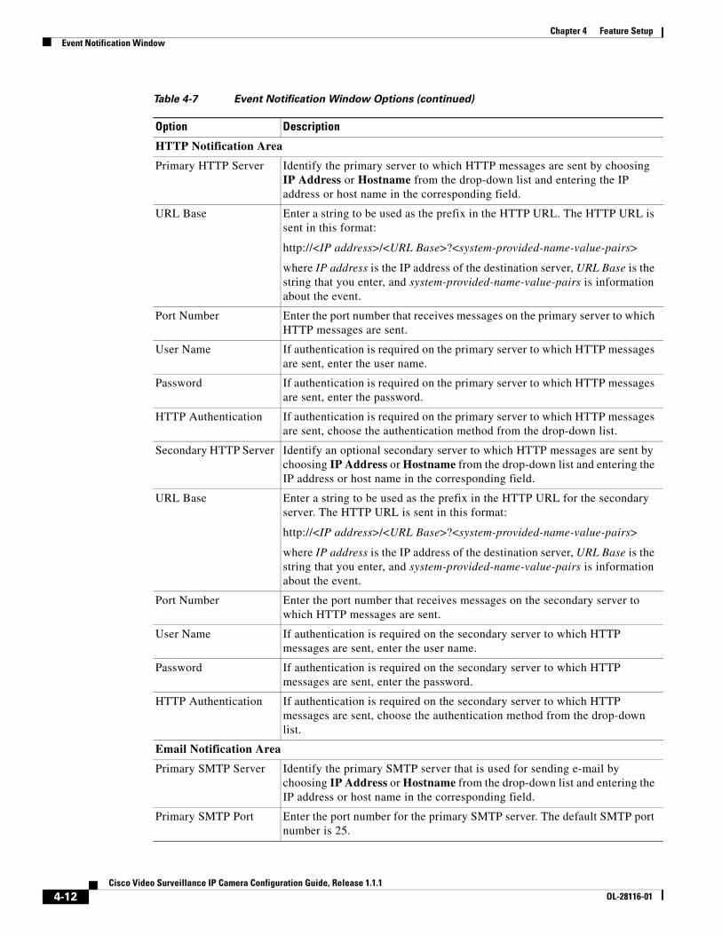
HTTP Notification Area
Primary HTTP Server Identify the primary server to which HTTP messages are sent by choosing IP Address or Hostname from the drop-down list and entering the IP address or host name in the corresponding field.
URL Base Enter a string to be used as the prefix in the HTTP URL. The HTTP URL is sent in this format:
http://<IP address>/<URL Base>?<system-provided-name-value-pairs>
where IP address is the IP address of the destination server, URL Base is the string that you enter, and system-provided-name-value-pairs is information about the event.
Port Number Enter the port number that receives messages on the primary server to which HTTP messages are sent.
User Name If authentication is required on the primary server to which HTTP messages are sent, enter the user name.
Password If authentication is required on the primary server to which HTTP messages are sent, enter the password.
HTTP Authentication If authentication is required on the primary server to which HTTP messages are sent, choose the authentication method from the drop-down list.
Secondary HTTP Server Identify an optional secondary server to which HTTP messages are sent by choosing IP Address or Hostname from the drop-down list and entering the IP address or host name in the corresponding field.
URL Base Enter a string to be used as the prefix in the HTTP URL for the secondary server. The HTTP URL is sent in this format:
http://<IP address>/<URL Base>?<system-provided-name-value-pairs>
where IP address is the IP address of the destination server, URL Base is the string that you enter, and system-provided-name-value-pairs is information about the event.
Port Number Enter the port number that receives messages on the secondary server to which HTTP messages are sent.
User Name If authentication is required on the secondary server to which HTTP messages are sent, enter the user name.
Password If authentication is required on the secondary server to which HTTP messages are sent, enter the password.
HTTP Authentication If authentication is required on the secondary server to which HTTP messages are sent, choose the authentication method from the drop-down list.
Email Notification Area
Primary SMTP Server Identify the primary SMTP server that is used for sending e-mail by choosing IP Address or Hostname from the drop-down list and entering the IP address or host name in the corresponding field.
Primary SMTP Port Enter the port number for the primary SMTP server. The default SMTP port number is 25.
Table 4-7 Event Notification Window Options (continued)
Option Description
4-12Cisco Video Surveillance IP Camera Configuration Guide, Release 1.1.1
OL-28116-01
Chapter 4 Feature SetupEvent Notification Window
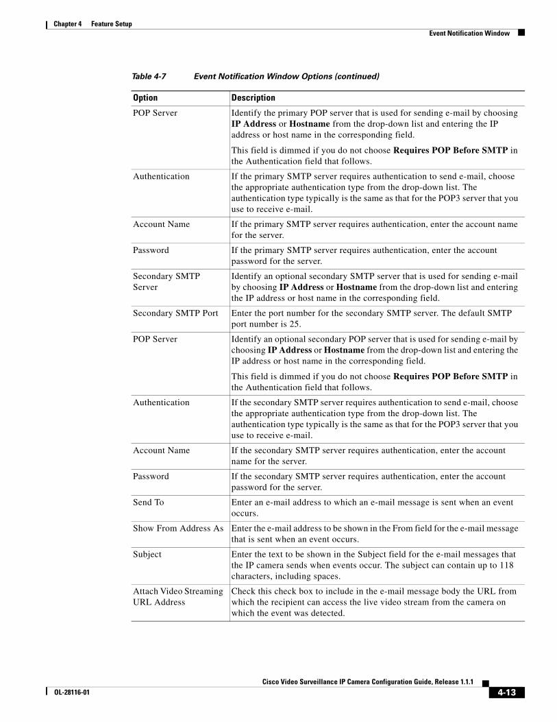
POP Server Identify the primary POP server that is used for sending e-mail by choosing IP Address or Hostname from the drop-down list and entering the IP address or host name in the corresponding field.
This field is dimmed if you do not choose Requires POP Before SMTP in the Authentication field that follows.
Authentication If the primary SMTP server requires authentication to send e-mail, choose the appropriate authentication type from the drop-down list. The authentication type typically is the same as that for the POP3 server that you use to receive e-mail.
Account Name If the primary SMTP server requires authentication, enter the account name for the server.
Password If the primary SMTP server requires authentication, enter the account password for the server.
Secondary SMTP Server
Identify an optional secondary SMTP server that is used for sending e-mail by choosing IP Address or Hostname from the drop-down list and entering the IP address or host name in the corresponding field.
Secondary SMTP Port Enter the port number for the secondary SMTP server. The default SMTP port number is 25.
POP Server Identify an optional secondary POP server that is used for sending e-mail by choosing IP Address or Hostname from the drop-down list and entering the IP address or host name in the corresponding field.
This field is dimmed if you do not choose Requires POP Before SMTP in the Authentication field that follows.
Authentication If the secondary SMTP server requires authentication to send e-mail, choose the appropriate authentication type from the drop-down list. The authentication type typically is the same as that for the POP3 server that you use to receive e-mail.
Account Name If the secondary SMTP server requires authentication, enter the account name for the server.
Password If the secondary SMTP server requires authentication, enter the account password for the server.
Send To Enter an e-mail address to which an e-mail message is sent when an event occurs.
Show From Address As Enter the e-mail address to be shown in the From field for the e-mail message that is sent when an event occurs.
Subject Enter the text to be shown in the Subject field for the e-mail messages that the IP camera sends when events occur. The subject can contain up to 118 characters, including spaces.
Attach Video Streaming URL Address
Check this check box to include in the e-mail message body the URL from which the recipient can access the live video stream from the camera on which the event was detected.
Table 4-7 Event Notification Window Options (continued)
Option Description
4-13Cisco Video Surveillance IP Camera Configuration Guide, Release 1.1.1
OL-28116-01
Chapter 4 Feature SetupEvent Notification Window
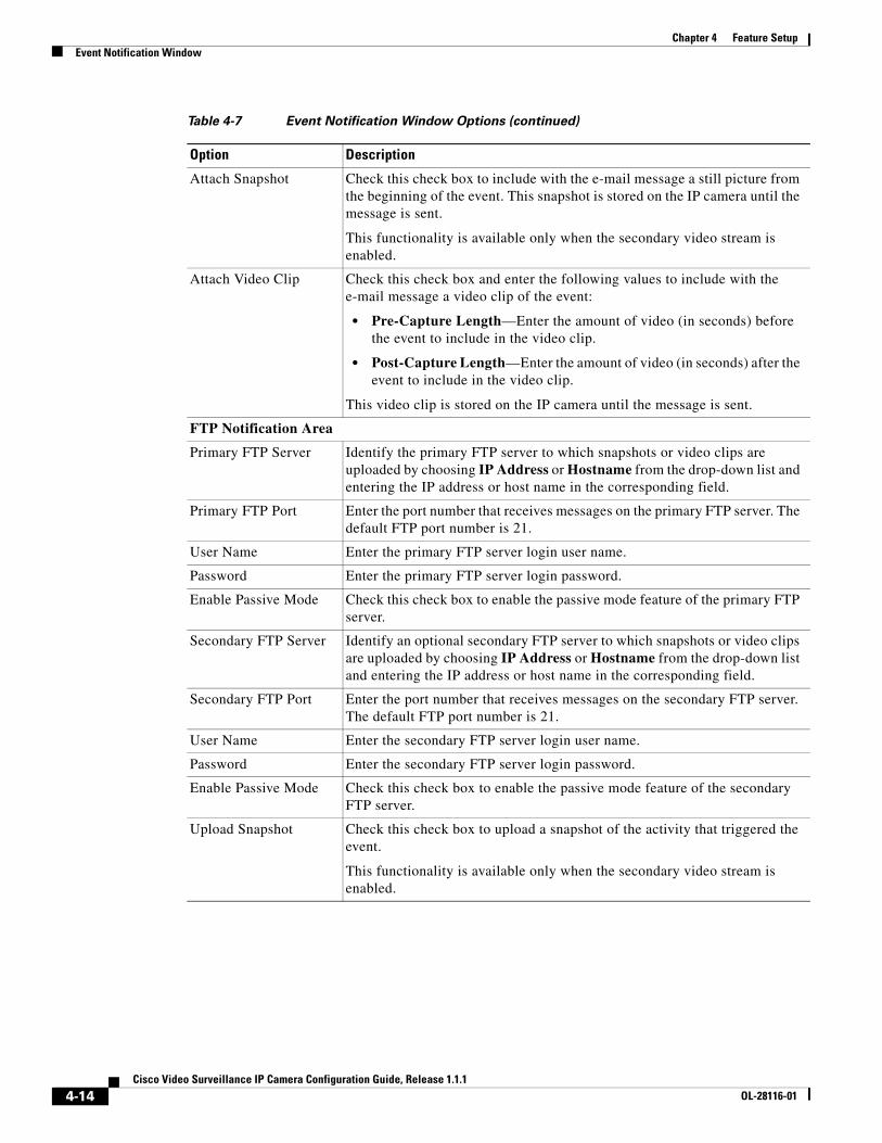
Attach Snapshot Check this check box to include with the e-mail message a still picture from the beginning of the event. This snapshot is stored on the IP camera until the message is sent.
This functionality is available only when the secondary video stream is enabled.
Attach Video Clip Check this check box and enter the following values to include with the e-mail message a video clip of the event:
• Pre-Capture Length—Enter the amount of video (in seconds) before the event to include in the video clip.
• Post-Capture Length—Enter the amount of video (in seconds) after the event to include in the video clip.
This video clip is stored on the IP camera until the message is sent.
FTP Notification Area
Primary FTP Server Identify the primary FTP server to which snapshots or video clips are uploaded by choosing IP Address or Hostname from the drop-down list and entering the IP address or host name in the corresponding field.
Primary FTP Port Enter the port number that receives messages on the primary FTP server. The default FTP port number is 21.
User Name Enter the primary FTP server login user name.
Password Enter the primary FTP server login password.
Enable Passive Mode Check this check box to enable the passive mode feature of the primary FTP server.
Secondary FTP Server Identify an optional secondary FTP server to which snapshots or video clips are uploaded by choosing IP Address or Hostname from the drop-down list and entering the IP address or host name in the corresponding field.
Secondary FTP Port Enter the port number that receives messages on the secondary FTP server. The default FTP port number is 21.
User Name Enter the secondary FTP server login user name.
Password Enter the secondary FTP server login password.
Enable Passive Mode Check this check box to enable the passive mode feature of the secondary FTP server.
Upload Snapshot Check this check box to upload a snapshot of the activity that triggered the event.
This functionality is available only when the secondary video stream is enabled.
Table 4-7 Event Notification Window Options (continued)
Option Description
4-14Cisco Video Surveillance IP Camera Configuration Guide, Release 1.1.1
OL-28116-01
Chapter 4 Feature SetupEvent Notification Window
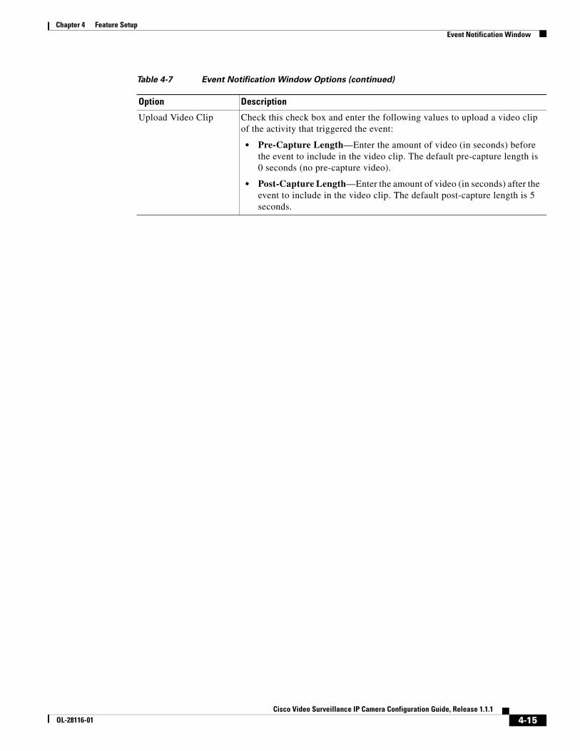
Upload Video Clip Check this check box and enter the following values to upload a video clip of the activity that triggered the event:
• Pre-Capture Length—Enter the amount of video (in seconds) before the event to include in the video clip. The default pre-capture length is 0 seconds (no pre-capture video).
• Post-Capture Length—Enter the amount of video (in seconds) after the event to include in the video clip. The default post-capture length is 5 seconds.
Table 4-7 Event Notification Window Options (continued)
Option Description
4-15Cisco Video Surveillance IP Camera Configuration Guide, Release 1.1.1
OL-28116-01

Chapter 4 Feature SetupEvent Notification Window
4-16Cisco Video Surveillance IP Camera Configuration Guide, Release 1.1.1
OL-28116-01
Cisco Video SurveilOL-28116-01
C H A P T E R 5
Network SetupThe Network Setup windows let you configure various network-related settings for the IP camera.
The following sections describe the Network Setup windows in detail:
• Basic Window, page 5-1
• IP Addressing Window, page 5-2
• Time Window, page 5-4
• Discovery Window, page 5-5
• IP Filter Window, page 5-6
• QoS Window, page 5-7
Basic WindowThe Basic window provides options for identifying the IP camera and controlling basic operations.
To display the Basic window, perform the following steps:
Procedure
Step 1 From the IP camera user interface, click the Setup link.
Step 2 Click Network Setup to expand the menu.
Step 3 From the Network Setup menu, click Basic.
The Basic window appears. If you change any options in this window, you must click the Save Settings button to save the changes. If you do not click this button, changes are not retained when you exit the window. Save Settings appears at the bottom of the window. You may need to scroll down to it.
Table 5-1 describes the options in the Basic window.
5-1lance IP Camera Configuration Guide, Release 1.1.1
Chapter 5 Network SetupIP Addressing Window
IP Addressing WindowThe IP Addressing window provides options for configuring the IP address of the IP camera.
To display the Basic window, perform the following steps:
Procedure
Step 1 From the IP camera user interface, click the Setup link.
Step 2 Click Network Setup to expand the menu.
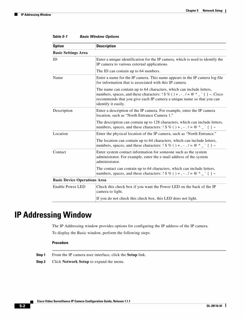
Table 5-1 Basic Window Options
Option Description
Basic Settings Area
ID Enter a unique identification for the IP camera, which is used to identify the IP camera to various external applications.
The ID can contain up to 64 numbers.
Name Enter a name for the IP camera. This name appears in the IP camera log file for information that is associated with this IP camera.
The name can contain up to 64 characters, which can include letters, numbers, spaces, and these characters: ! $ % ( ) + , - . / = @ ^ _ ` { } ~. Cisco recommends that you give each IP camera a unique name so that you can identify it easily.
Description Enter a description of the IP camera. For example, enter the IP camera location, such as “North Entrance Camera 1.”
The description can contain up to 128 characters, which can include letters, numbers, spaces, and these characters: ! $ % ( ) + , - . / = @ ^ _ ` { } ~
Location Enter the physical location of the IP camera, such as “North Entrance.”
The location can contain up to 64 characters, which can include letters, numbers, spaces, and these characters: ! $ % ( ) + , - . / = @ ^ _ ` { } ~
Contact Enter system contact information for someone such as the system administrator. For example, enter the e-mail address of the system administrator.
The contact can contain up to 64 characters, which can include letters, numbers, spaces, and these characters: ! $ % ( ) + , - . / = @ ^ _ ` { } ~
Basic Device Operations Area
Enable Power LED Check this check box if you want the Power LED on the back of the IP camera to light.
If you do not check this check box, this LED does not light.
5-2Cisco Video Surveillance IP Camera Configuration Guide, Release 1.1.1
OL-28116-01
Chapter 5 Network SetupIP Addressing Window
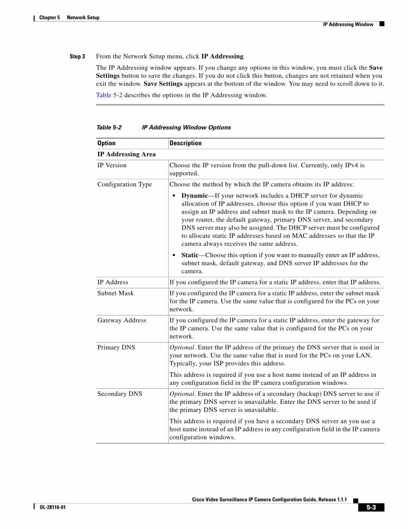
Step 3 From the Network Setup menu, click IP Addressing.
The IP Addressing window appears. If you change any options in this window, you must click the Save Settings button to save the changes. If you do not click this button, changes are not retained when you exit the window. Save Settings appears at the bottom of the window. You may need to scroll down to it.
Table 5-2 describes the options in the IP Addressing window.
Table 5-2 IP Addressing Window Options
Option Description
IP Addressing Area
IP Version Choose the IP version from the pull-down list. Currently, only IPv4 is supported.
Configuration Type Choose the method by which the IP camera obtains its IP address:
• Dynamic—If your network includes a DHCP server for dynamic allocation of IP addresses, choose this option if you want DHCP to assign an IP address and subnet mask to the IP camera. Depending on your router, the default gateway, primary DNS server, and secondary DNS server may also be assigned. The DHCP server must be configured to allocate static IP addresses based on MAC addresses so that the IP camera always receives the same address.
• Static—Choose this option if you want to manually enter an IP address, subnet mask, default gateway, and DNS server IP addresses for the camera.
IP Address If you configured the IP camera for a static IP address, enter that IP address.
Subnet Mask If you configured the IP camera for a static IP address, enter the subnet mask for the IP camera. Use the same value that is configured for the PCs on your network.
Gateway Address If you configured the IP camera for a static IP address, enter the gateway for the IP camera. Use the same value that is configured for the PCs on your network.
Primary DNS Optional. Enter the IP address of the primary the DNS server that is used in your network. Use the same value that is used for the PCs on your LAN. Typically, your ISP provides this address.
This address is required if you use a host name instead of an IP address in any configuration field in the IP camera configuration windows.
Secondary DNS Optional. Enter the IP address of a secondary (backup) DNS server to use if the primary DNS server is unavailable. Enter the DNS server to be used if the primary DNS server is unavailable.
This address is required if you have a secondary DNS server an you use a host name instead of an IP address in any configuration field in the IP camera configuration windows.
5-3Cisco Video Surveillance IP Camera Configuration Guide, Release 1.1.1
OL-28116-01
Chapter 5 Network SetupTime Window
Time WindowThe Time window provides options for setting and maintaining the time of the IP camera.
To display the Time window, perform the following steps:
Procedure
Step 1 From the IP camera user interface, click the Setup link.
Step 2 Click Network Setup to expand the menu.
Step 3 From the Network Setup menu, click Time.
The Time window appears. If you change any options in this window, you must click the Save Settings button to save the changes. If you do not click this button, changes are not retained when you exit the window. Save Settings appears at the bottom of the window. You may need to scroll down to it.
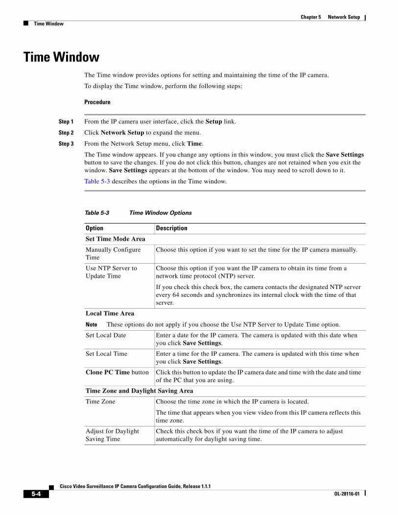
Table 5-3 describes the options in the Time window.
Table 5-3 Time Window Options
Option Description
Set Time Mode Area
Manually Configure Time
Choose this option if you want to set the time for the IP camera manually.
Use NTP Server to Update Time
Choose this option if you want the IP camera to obtain its time from a network time protocol (NTP) server.
If you check this check box, the camera contacts the designated NTP server every 64 seconds and synchronizes its internal clock with the time of that server.
Local Time Area
Note These options do not apply if you choose the Use NTP Server to Update Time option.
Set Local Date Enter a date for the IP camera. The camera is updated with this date when you click Save Settings.
Set Local Time Enter a time for the IP camera. The camera is updated with this time when you click Save Settings.
Clone PC Time button Click this button to update the IP camera date and time with the date and time of the PC that you are using.
Time Zone and Daylight Saving Area
Time Zone Choose the time zone in which the IP camera is located.
The time that appears when you view video from this IP camera reflects this time zone.
Adjust for Daylight Saving Time
Check this check box if you want the time of the IP camera to adjust automatically for daylight saving time.
5-4Cisco Video Surveillance IP Camera Configuration Guide, Release 1.1.1
OL-28116-01
Chapter 5 Network SetupDiscovery Window
Discovery WindowThe Discovery window provides options for configuring the IP camera to work with Cisco Discovery Protocol or Bonjour. These applications facilitate monitoring and management of your network.
To display the Discovery window, perform the following steps:
Procedure
Step 1 From the IP camera user interface, click the Setup link.
Step 2 Click Network Setup to expand the menu.
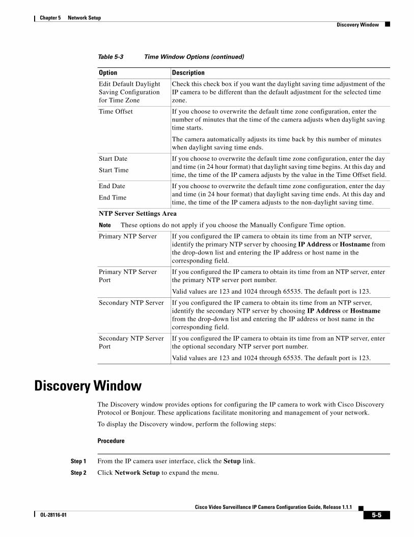
Edit Default Daylight Saving Configuration for Time Zone
Check this check box if you want the daylight saving time adjustment of the IP camera to be different than the default adjustment for the selected time zone.
Time Offset If you choose to overwrite the default time zone configuration, enter the number of minutes that the time of the camera adjusts when daylight saving time starts.
The camera automatically adjusts its time back by this number of minutes when daylight saving time ends.
Start Date
Start Time
If you choose to overwrite the default time zone configuration, enter the day and time (in 24 hour format) that daylight saving time begins. At this day and time, the time of the IP camera adjusts by the value in the Time Offset field.
End Date
End Time
If you choose to overwrite the default time zone configuration, enter the day and time (in 24 hour format) that daylight saving time ends. At this day and time, the time of the IP camera adjusts to the non-daylight saving time.
NTP Server Settings Area
Note These options do not apply if you choose the Manually Configure Time option.
Primary NTP Server If you configured the IP camera to obtain its time from an NTP server, identify the primary NTP server by choosing IP Address or Hostname from the drop-down list and entering the IP address or host name in the corresponding field.
Primary NTP Server Port
If you configured the IP camera to obtain its time from an NTP server, enter the primary NTP server port number.
Valid values are 123 and 1024 through 65535. The default port is 123.
Secondary NTP Server If you configured the IP camera to obtain its time from an NTP server, identify the secondary NTP server by choosing IP Address or Hostname from the drop-down list and entering the IP address or host name in the corresponding field.
Secondary NTP Server Port
If you configured the IP camera to obtain its time from an NTP server, enter the optional secondary NTP server port number.
Valid values are 123 and 1024 through 65535. The default port is 123.
Table 5-3 Time Window Options (continued)
Option Description
5-5Cisco Video Surveillance IP Camera Configuration Guide, Release 1.1.1
OL-28116-01
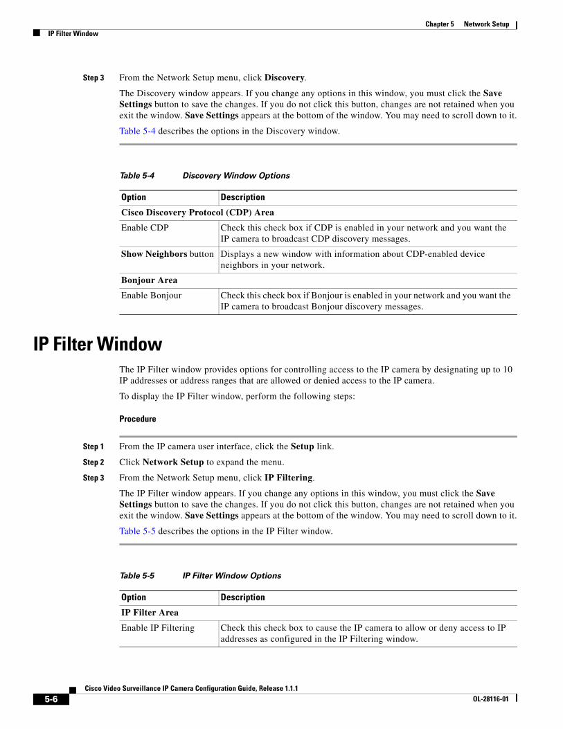
Chapter 5 Network SetupIP Filter Window
Step 3 From the Network Setup menu, click Discovery.
The Discovery window appears. If you change any options in this window, you must click the Save Settings button to save the changes. If you do not click this button, changes are not retained when you exit the window. Save Settings appears at the bottom of the window. You may need to scroll down to it.
Table 5-4 describes the options in the Discovery window.
IP Filter WindowThe IP Filter window provides options for controlling access to the IP camera by designating up to 10 IP addresses or address ranges that are allowed or denied access to the IP camera.
To display the IP Filter window, perform the following steps:
Procedure
Step 1 From the IP camera user interface, click the Setup link.
Step 2 Click Network Setup to expand the menu.
Step 3 From the Network Setup menu, click IP Filtering.
The IP Filter window appears. If you change any options in this window, you must click the Save Settings button to save the changes. If you do not click this button, changes are not retained when you exit the window. Save Settings appears at the bottom of the window. You may need to scroll down to it.
Table 5-5 describes the options in the IP Filter window.
Table 5-4 Discovery Window Options
Option Description
Cisco Discovery Protocol (CDP) Area
Enable CDP Check this check box if CDP is enabled in your network and you want the IP camera to broadcast CDP discovery messages.
Show Neighbors button Displays a new window with information about CDP-enabled device neighbors in your network.
Bonjour Area
Enable Bonjour Check this check box if Bonjour is enabled in your network and you want the IP camera to broadcast Bonjour discovery messages.
Table 5-5 IP Filter Window Options
Option Description
IP Filter Area
Enable IP Filtering Check this check box to cause the IP camera to allow or deny access to IP addresses as configured in the IP Filtering window.
5-6Cisco Video Surveillance IP Camera Configuration Guide, Release 1.1.1
OL-28116-01
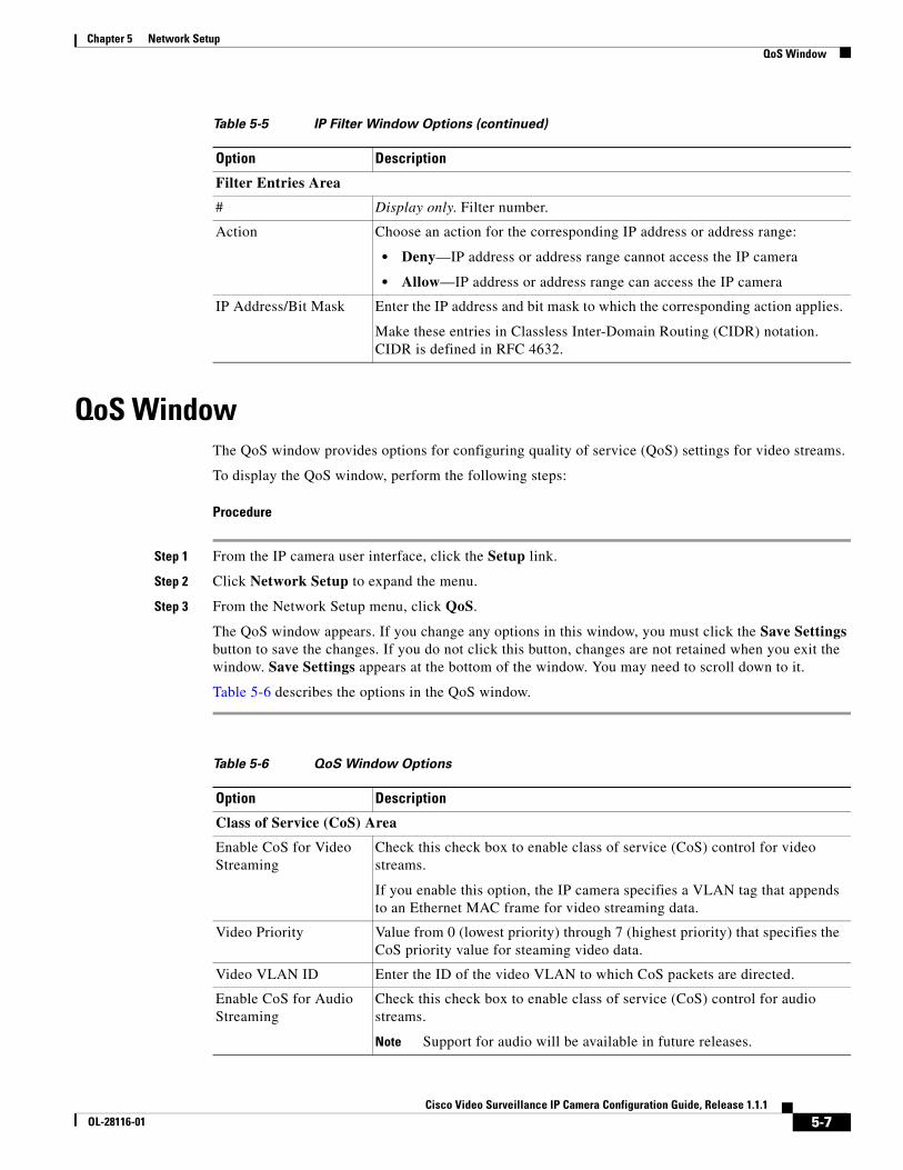
Chapter 5 Network SetupQoS Window
QoS WindowThe QoS window provides options for configuring quality of service (QoS) settings for video streams.
To display the QoS window, perform the following steps:
Procedure
Step 1 From the IP camera user interface, click the Setup link.
Step 2 Click Network Setup to expand the menu.
Step 3 From the Network Setup menu, click QoS.
The QoS window appears. If you change any options in this window, you must click the Save Settings button to save the changes. If you do not click this button, changes are not retained when you exit the window. Save Settings appears at the bottom of the window. You may need to scroll down to it.
Table 5-6 describes the options in the QoS window.
Filter Entries Area
# Display only. Filter number.
Action Choose an action for the corresponding IP address or address range:
• Deny—IP address or address range cannot access the IP camera
• Allow—IP address or address range can access the IP camera
IP Address/Bit Mask Enter the IP address and bit mask to which the corresponding action applies.
Make these entries in Classless Inter-Domain Routing (CIDR) notation. CIDR is defined in RFC 4632.
Table 5-5 IP Filter Window Options (continued)
Option Description
Table 5-6 QoS Window Options
Option Description
Class of Service (CoS) Area
Enable CoS for Video Streaming
Check this check box to enable class of service (CoS) control for video streams.
If you enable this option, the IP camera specifies a VLAN tag that appends to an Ethernet MAC frame for video streaming data.
Video Priority Value from 0 (lowest priority) through 7 (highest priority) that specifies the CoS priority value for steaming video data.
Video VLAN ID Enter the ID of the video VLAN to which CoS packets are directed.
Enable CoS for Audio Streaming
Check this check box to enable class of service (CoS) control for audio streams.
Note Support for audio will be available in future releases.
5-7Cisco Video Surveillance IP Camera Configuration Guide, Release 1.1.1
OL-28116-01
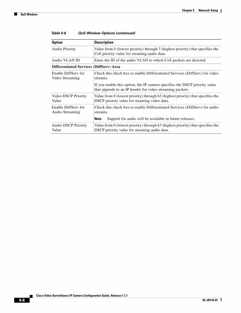
Chapter 5 Network SetupQoS Window
Audio Priority Value from 0 (lowest priority) through 7 (highest priority) that specifies the CoS priority value for steaming audio data.
Audio VLAN ID Enter the ID of the audio VLAN to which CoS packets are directed.
Differentiated Services (DiffServ) Area
Enable DiffServ for Video Streaming
Check this check box to enable Differentiated Services (DiffServ) for video streams.
If you enable this option, the IP camera specifies the DSCP priority value that appends to an IP header for video streaming packets.
Video DSCP Priority Value
Value from 0 (lowest priority) through 63 (highest priority) that specifies the DSCP priority value for steaming video data.
Enable DiffServ for Audio Streaming
Check this check box to enable Differentiated Services (DiffServ) for audio streams.
Note Support for audio will be available in future releases.
Audio DSCP Priority Value
Value from 0 (lowest priority) through 63 (highest priority) that specifies the DSCP priority value for steaming audio data.
Table 5-6 QoS Window Options (continued)
Option Description
5-8Cisco Video Surveillance IP Camera Configuration Guide, Release 1.1.1
OL-28116-01
Cisco Video SurveilOL-28116-01
C H A P T E R 6
AdministrationThe Administrator windows lets you perform several general administrative operations, including enabling HTTP and HTTPS access to the IP camera, configuring users, resetting or rebooting the IP camera, and updating firmware.
The following sections describe the Administration windows in detail:
• Initialization Window, page 6-1
• User Window, page 6-3
• Maintenance Window, page 6-4
• Firmware Window, page 6-6
• Device Processes Window, page 6-7
• Password Complexity Window, page 6-8
Initialization WindowThe Account Initialization window provides options for configuring passwords for the IP camera default administrator accounts, and for configuring which protocols can be used to access the IP camera.
The IP camera always has an HTTP/HTTPS administrator who can access the IP camera through an HTTP or HTTPS connection. The name of this administrator is admin. The password is configurable.
If you want to access the IP camera through SSH, you must configure a password for an SSH administrator. The name of this administrator is root. The password is configurable.
To display the Initialization window, perform the following steps:
Procedure
Step 1 From the IP camera user interface, click the Setup link.
Step 2 Click Administration to expand the menu.
Step 3 From the Administration menu, click Initialization.
The Initialization window appears. If you change any options in this window, you must click the Save Settings button to save the changes. If you do not click this button, changes are not retained when you exit the window. Save Settings appears at the bottom of the window. You may need to scroll down to it.
6-1lance IP Camera Configuration Guide, Release 1.1.1
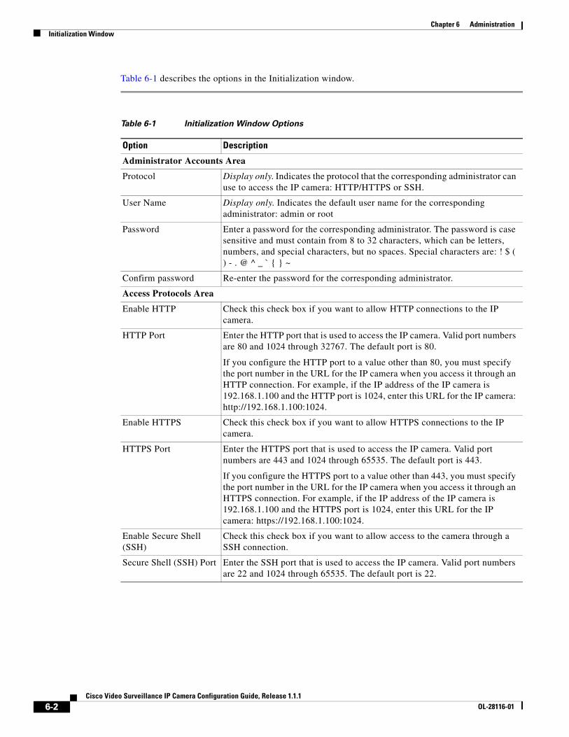
Chapter 6 AdministrationInitialization Window
Table 6-1 describes the options in the Initialization window.
Table 6-1 Initialization Window Options
Option Description
Administrator Accounts Area
Protocol Display only. Indicates the protocol that the corresponding administrator can use to access the IP camera: HTTP/HTTPS or SSH.
User Name Display only. Indicates the default user name for the corresponding administrator: admin or root
Password Enter a password for the corresponding administrator. The password is case sensitive and must contain from 8 to 32 characters, which can be letters, numbers, and special characters, but no spaces. Special characters are: ! $ ( ) - . @ ^ _ ` { } ~
Confirm password Re-enter the password for the corresponding administrator.
Access Protocols Area
Enable HTTP Check this check box if you want to allow HTTP connections to the IP camera.
HTTP Port Enter the HTTP port that is used to access the IP camera. Valid port numbers are 80 and 1024 through 32767. The default port is 80.
If you configure the HTTP port to a value other than 80, you must specify the port number in the URL for the IP camera when you access it through an HTTP connection. For example, if the IP address of the IP camera is 192.168.1.100 and the HTTP port is 1024, enter this URL for the IP camera: http://192.168.1.100:1024.
Enable HTTPS Check this check box if you want to allow HTTPS connections to the IP camera.
HTTPS Port Enter the HTTPS port that is used to access the IP camera. Valid port numbers are 443 and 1024 through 65535. The default port is 443.
If you configure the HTTPS port to a value other than 443, you must specify the port number in the URL for the IP camera when you access it through an HTTPS connection. For example, if the IP address of the IP camera is 192.168.1.100 and the HTTPS port is 1024, enter this URL for the IP camera: https://192.168.1.100:1024.
Enable Secure Shell (SSH)
Check this check box if you want to allow access to the camera through a SSH connection.
Secure Shell (SSH) Port Enter the SSH port that is used to access the IP camera. Valid port numbers are 22 and 1024 through 65535. The default port is 22.
6-2Cisco Video Surveillance IP Camera Configuration Guide, Release 1.1.1
OL-28116-01
Chapter 6 AdministrationUser Window
User WindowThe User window lets you configure the following types of IP camera users:
• Administrator—Can access all IP camera windows, features, and functions.
• Viewer—Can access only the Camera Video & Control window and all features in that window except:
– Video image controls
– Set Current Preset as Home button
– Add Preset Position button
– Deleted Selected Preset button
– Pan/tilt speed controls
– Motion detection controls
There is always at least one user with Administrator privileges configured. The user name of this user is “admin.” You can configure up to four additional users and assign privilege levels to each one.
When you configure users, follow these guidelines:
• After you enter a name, password, and privilege level for a user, click Add next to the user information to save your changes.
• To change the password for an existing user, click Change next to the user name.
• To remove a user, click Delete next to the user. If you delete a user who is logged into the IP camera, the user remains logged in and can continue access the IP camera.
• To change the name of a user, you must delete the user then create a new user.
To display the User window, perform the following steps:
Procedure
Step 1 From the IP camera user interface, click the Setup link.
Step 2 Click Administration to expand the menu.
Step 3 From the Administration menu, click Users.
The User window appears. If you change any options in this window, you must click the Save Settings button to save the changes. If you do not click this button, changes are not retained when you exit the window. Save Settings appears at the bottom of the window. You may need to scroll down to it.
Table 6-2 describes the options in the User window.
6-3Cisco Video Surveillance IP Camera Configuration Guide, Release 1.1.1
OL-28116-01
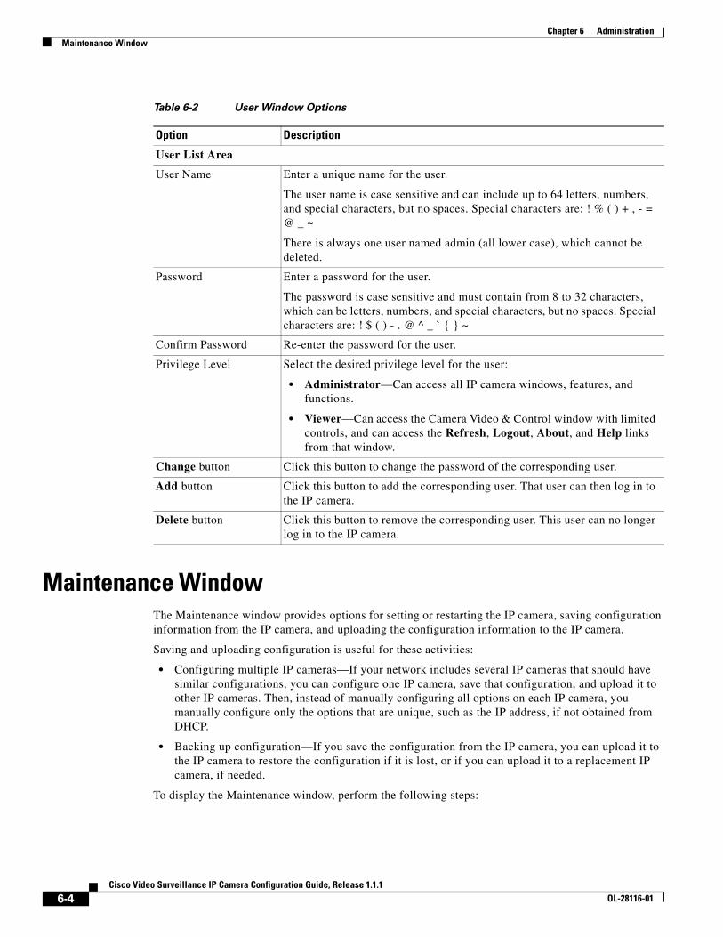
Chapter 6 AdministrationMaintenance Window
Maintenance WindowThe Maintenance window provides options for setting or restarting the IP camera, saving configuration information from the IP camera, and uploading the configuration information to the IP camera.
Saving and uploading configuration is useful for these activities:
• Configuring multiple IP cameras—If your network includes several IP cameras that should have similar configurations, you can configure one IP camera, save that configuration, and upload it to other IP cameras. Then, instead of manually configuring all options on each IP camera, you manually configure only the options that are unique, such as the IP address, if not obtained from DHCP.
• Backing up configuration—If you save the configuration from the IP camera, you can upload it to the IP camera to restore the configuration if it is lost, or if you can upload it to a replacement IP camera, if needed.
To display the Maintenance window, perform the following steps:
Table 6-2 User Window Options
Option Description
User List Area
User Name Enter a unique name for the user.
The user name is case sensitive and can include up to 64 letters, numbers, and special characters, but no spaces. Special characters are: ! % ( ) + , - = @ _ ~
There is always one user named admin (all lower case), which cannot be deleted.
Password Enter a password for the user.
The password is case sensitive and must contain from 8 to 32 characters, which can be letters, numbers, and special characters, but no spaces. Special characters are: ! $ ( ) - . @ ^ _ ` { } ~
Confirm Password Re-enter the password for the user.
Privilege Level Select the desired privilege level for the user:
• Administrator—Can access all IP camera windows, features, and functions.
• Viewer—Can access the Camera Video & Control window with limited controls, and can access the Refresh, Logout, About, and Help links from that window.
Change button Click this button to change the password of the corresponding user.
Add button Click this button to add the corresponding user. That user can then log in to the IP camera.
Delete button Click this button to remove the corresponding user. This user can no longer log in to the IP camera.
6-4Cisco Video Surveillance IP Camera Configuration Guide, Release 1.1.1
OL-28116-01
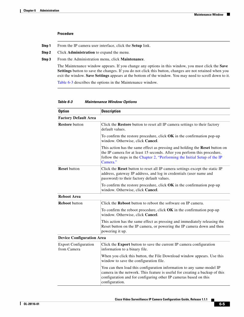
Chapter 6 AdministrationMaintenance Window
Procedure
Step 1 From the IP camera user interface, click the Setup link.
Step 2 Click Administration to expand the menu.
Step 3 From the Administration menu, click Maintenance.
The Maintenance window appears. If you change any options in this window, you must click the Save Settings button to save the changes. If you do not click this button, changes are not retained when you exit the window. Save Settings appears at the bottom of the window. You may need to scroll down to it.
Table 6-3 describes the options in the Maintenance window.
Table 6-3 Maintenance Window Options
Option Description
Factory Default Area
Restore button Click the Restore button to reset all IP camera settings to their factory default values.
To confirm the restore procedure, click OK in the confirmation pop-up window. Otherwise, click Cancel.
This action has the same effect as pressing and holding the Reset button on the IP camera for at least 15 seconds. After you perform this procedure, follow the steps in the Chapter 2, “Performing the Initial Setup of the IP Camera.”
Reset button Click the Reset button to reset all IP camera settings except the static IP address, gateway IP address, and log in credentials (user name and password) to their factory default values.
To confirm the restore procedure, click OK in the confirmation pop-up window. Otherwise, click Cancel.
Reboot Area
Reboot button Click the Reboot button to reboot the software on IP camera.
To confirm the reboot procedure, click OK in the confirmation pop-up window. Otherwise, click Cancel.
This action has the same effect as pressing and immediately releasing the Reset button on the IP camera, or powering the IP camera down and then powering it up.
Device Configuration Area
Export Configuration from Camera
Click the Export button to save the current IP camera configuration information to a binary file.
When you click this button, the File Download window appears. Use this window to save the configuration file.
You can then load this configuration information to any same-model IP camera in the network. This feature is useful for creating a backup of this configuration and for configuring other IP cameras based on this configuration.
6-5Cisco Video Surveillance IP Camera Configuration Guide, Release 1.1.1
OL-28116-01
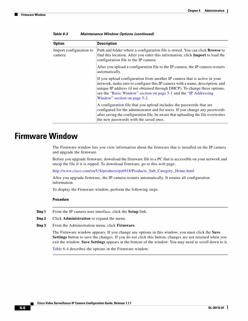
Chapter 6 AdministrationFirmware Window
Firmware WindowThe Firmware window lets you view information about the firmware that is installed on the IP camera and upgrade the firmware.
Before you upgrade firmware, download the firmware file to a PC that is accessible on your network and unzip the file if it is zipped. To download firmware, go to this web page:
http://www.cisco.com/en/US/products/ps6918/Products_Sub_Category_Home.html
After you upgrade firmware, the IP camera restarts automatically. It retains all configuration information.
To display the Firmware window, perform the following steps:
Procedure
Step 1 From the IP camera user interface, click the Setup link.
Step 2 Click Administration to expand the menu.
Step 3 From the Administration menu, click Firmware.
The Firmware window appears. If you change any options in this window, you must click the Save Settings button to save the changes. If you do not click this button, changes are not retained when you exit the window. Save Settings appears at the bottom of the window. You may need to scroll down to it.
Table 6-4 describes the options in the Firmware window.
Import configuration to camera
Path and folder where a configuration file is stored. You can click Browse to find this location. After you enter this information, click Import to load the configuration file to the IP camera.
After you upload a configuration file to the IP camera, the IP camera restarts automatically.
If you upload configuration from another IP camera that is active in your network, make sure to configure this IP camera with a name, description, and unique IP address (if not obtained through DHCP). To change these options, see the “Basic Window” section on page 5-1 and the “IP Addressing Window” section on page 5-2.
A configuration file that you upload includes the passwords that are configured for the administrator and for users. If you change any passwords after saving the configuration file, be aware that uploading the file overwrites the new passwords with the saved ones.
Table 6-3 Maintenance Window Options (continued)
Option Description
6-6Cisco Video Surveillance IP Camera Configuration Guide, Release 1.1.1
OL-28116-01
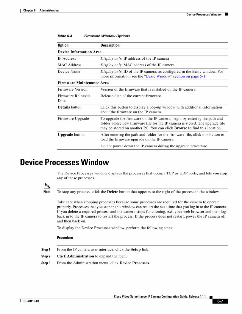
Chapter 6 AdministrationDevice Processes Window
Device Processes WindowThe Device Processes window displays the processes that occupy TCP or UDP ports, and lets you stop any of these processes.
Note To stop any process, click the Delete button that appears to the right of the process in the window.
Take care when stopping processes because some processes are required for the camera to operate properly. Processes that you stop in this window can restart the next time that you log in to the IP camera. If you delete a required process and the camera stops functioning, exit your web browser and then log back in to the IP camera to restart the process. If the process does not restart, power the IP camera off and then back on.
To display the Device Processes window, perform the following steps:
Procedure
Step 1 From the IP camera user interface, click the Setup link.
Step 2 Click Administration to expand the menu.
Step 3 From the Administration menu, click Device Processes.
Table 6-4 Firmware Window Options
Option Description
Device Information Area
IP Address Display only. IP address of the IP camera
MAC Address Display only. MAC address of the IP camera.
Device Name Display only. ID of the IP camera, as configured in the Basic window. For more information, see the “Basic Window” section on page 5-1.
Firmware Maintenance Area
Firmware Version Version of the firmware that is installed on the IP camera.
Firmware Released Date
Release date of the current firmware.
Details button Click this button to display a pop-up window with additional information about the firmware on the IP camera.
Firmware Upgrade To upgrade the firmware on the IP camera, begin by entering the path and folder where new firmware file for the IP camera is stored. The upgrade file may be stored on another PC. You can click Browse to find this location.
Upgrade button After entering the path and folder for the firmware file, click this button to load the firmware upgrade on the IP camera.
Do not power down the IP camera during the upgrade procedure.
6-7Cisco Video Surveillance IP Camera Configuration Guide, Release 1.1.1
OL-28116-01
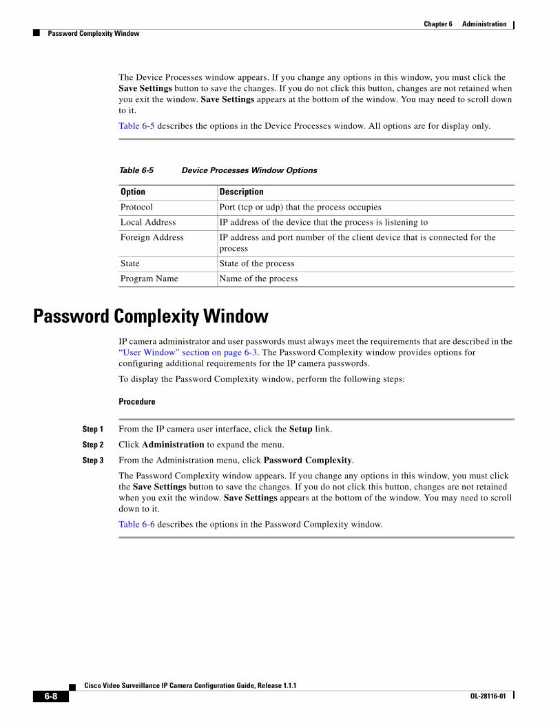
Chapter 6 AdministrationPassword Complexity Window
The Device Processes window appears. If you change any options in this window, you must click the Save Settings button to save the changes. If you do not click this button, changes are not retained when you exit the window. Save Settings appears at the bottom of the window. You may need to scroll down to it.
Table 6-5 describes the options in the Device Processes window. All options are for display only.
Password Complexity WindowIP camera administrator and user passwords must always meet the requirements that are described in the “User Window” section on page 6-3. The Password Complexity window provides options for configuring additional requirements for the IP camera passwords.
To display the Password Complexity window, perform the following steps:
Procedure
Step 1 From the IP camera user interface, click the Setup link.
Step 2 Click Administration to expand the menu.
Step 3 From the Administration menu, click Password Complexity.
The Password Complexity window appears. If you change any options in this window, you must click the Save Settings button to save the changes. If you do not click this button, changes are not retained when you exit the window. Save Settings appears at the bottom of the window. You may need to scroll down to it.
Table 6-6 describes the options in the Password Complexity window.
Table 6-5 Device Processes Window Options
Option Description
Protocol Port (tcp or udp) that the process occupies
Local Address IP address of the device that the process is listening to
Foreign Address IP address and port number of the client device that is connected for the process
State State of the process
Program Name Name of the process
6-8Cisco Video Surveillance IP Camera Configuration Guide, Release 1.1.1
OL-28116-01
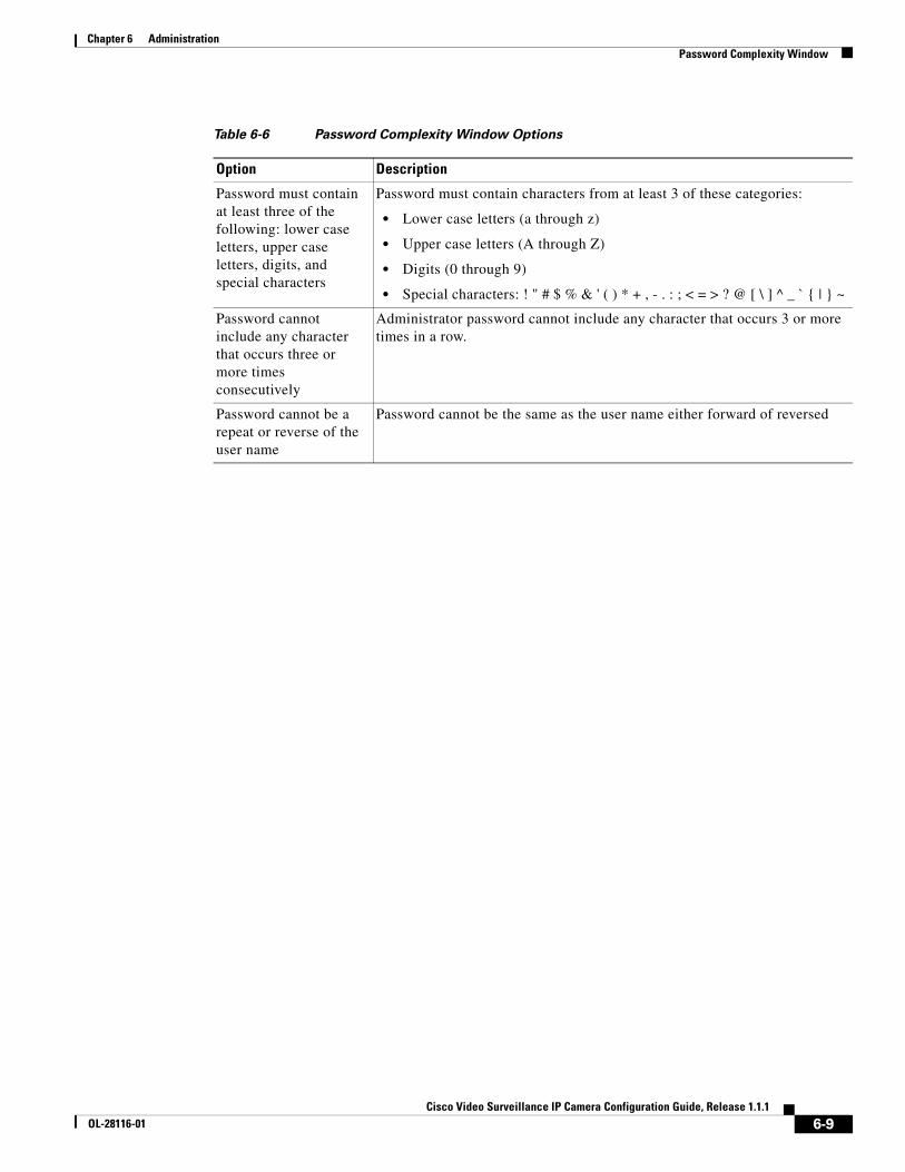
Chapter 6 AdministrationPassword Complexity Window
Table 6-6 Password Complexity Window Options
Option Description
Password must contain at least three of the following: lower case letters, upper case letters, digits, and special characters
Password must contain characters from at least 3 of these categories:
• Lower case letters (a through z)
• Upper case letters (A through Z)
• Digits (0 through 9)
• Special characters: ! " # $ % & ' ( ) * + , - . : ; < = > ? @ [ \ ] ^ _ ` { | } ~
Password cannot include any character that occurs three or more times consecutively
Administrator password cannot include any character that occurs 3 or more times in a row.
Password cannot be a repeat or reverse of the user name
Password cannot be the same as the user name either forward of reversed
6-9Cisco Video Surveillance IP Camera Configuration Guide, Release 1.1.1
OL-28116-01

Chapter 6 AdministrationPassword Complexity Window
6-10Cisco Video Surveillance IP Camera Configuration Guide, Release 1.1.1
OL-28116-01
Cisco Video SurveilOL-28116-01
C H A P T E R 7
Log ConfigurationThe Log windows let you set up and view the IP camera log file, which captures information about the IP camera and its activities.
The IP camera stores the log file in its internal SDRAM. If the SDRAM becomes full, the IP camera begins to overwrite existing information. To avoid losing log information, you can configure the IP camera to send log information to a Syslog server.
Caution Because the logs are stored in the internal camera SDRAM, all existing logs in the camera will be lost after a camera reboot, power-up, or power-down.
The following sections describe the Log windows in detail:
• Log Setup Window, page 7-1
• Local Log Window, page 7-4
Log Setup WindowThe Log Setup window provides options for configuring the log file and an optional syslog server on which to store log files.
To display the Log Setup window, perform the following steps:
Procedure
Step 1 From the IP camera user interface, click the Setup link.
Step 2 Click Log to expand the menu.
Step 3 From the Log menu, click Setup.
The Log Setup window appears. If you change any options in this window, you must click the Save Settings button to save the changes. If you do not click this button, changes are not retained when you exit the window. Save Settings appears at the bottom of the window. You may need to scroll down to it.
Table 7-1 describes the options in the Log Setup window.
7-1lance IP Camera Configuration Guide, Release 1.1.1
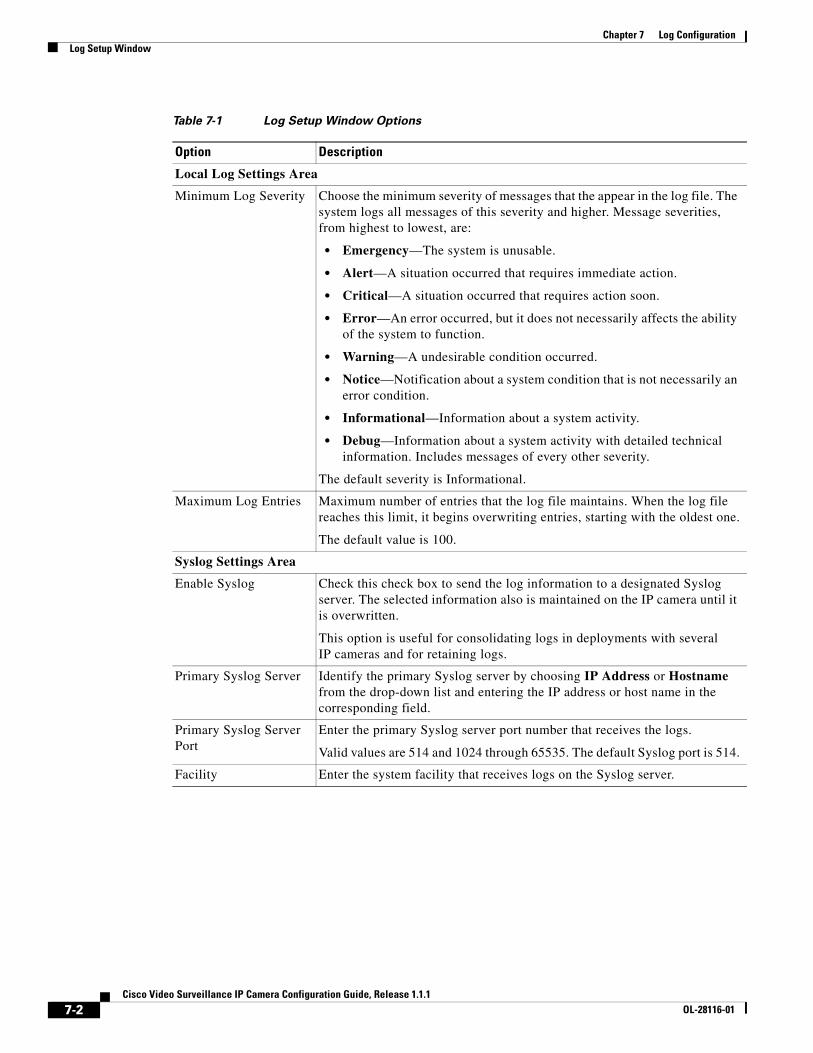
Chapter 7 Log ConfigurationLog Setup Window
Table 7-1 Log Setup Window Options
Option Description
Local Log Settings Area
Minimum Log Severity Choose the minimum severity of messages that the appear in the log file. The system logs all messages of this severity and higher. Message severities, from highest to lowest, are:
• Emergency—The system is unusable.
• Alert—A situation occurred that requires immediate action.
• Critical—A situation occurred that requires action soon.
• Error—An error occurred, but it does not necessarily affects the ability of the system to function.
• Warning—A undesirable condition occurred.
• Notice—Notification about a system condition that is not necessarily an error condition.
• Informational—Information about a system activity.
• Debug—Information about a system activity with detailed technical information. Includes messages of every other severity.
The default severity is Informational.
Maximum Log Entries Maximum number of entries that the log file maintains. When the log file reaches this limit, it begins overwriting entries, starting with the oldest one.
The default value is 100.
Syslog Settings Area
Enable Syslog Check this check box to send the log information to a designated Syslog server. The selected information also is maintained on the IP camera until it is overwritten.
This option is useful for consolidating logs in deployments with several IP cameras and for retaining logs.
Primary Syslog Server Identify the primary Syslog server by choosing IP Address or Hostname from the drop-down list and entering the IP address or host name in the corresponding field.
Primary Syslog Server Port
Enter the primary Syslog server port number that receives the logs.
Valid values are 514 and 1024 through 65535. The default Syslog port is 514.
Facility Enter the system facility that receives logs on the Syslog server.
7-2Cisco Video Surveillance IP Camera Configuration Guide, Release 1.1.1
OL-28116-01

Chapter 7 Log ConfigurationLog Setup Window
Minimum Log Severity Choose the minimum severity of messages that are sent to the Syslog server. The system sends all messages of this severity and higher. Message severities, from highest to lowest, are:
• Emergency—The system is unusable.
• Alert—A situation occurred that requires immediate action.
• Critical—A situation occurred that requires action soon.
• Error—An error occurred, but it does not necessarily affects the ability of the system to function.
• Warning—A undesirable condition occurred.
• Notice—Notification about a system condition that is not an error condition.
• Informational—Information about a system activity.
• Debug—Information about a system activity with detailed technical information. Includes messages of every other severity.
The default severity is Informational.
Secondary Syslog Server
Identify an optional secondary Syslog server by choosing IP Address or Hostname from the drop-down list and entering the IP address or host name in the corresponding field.
Secondary Syslog Server Port
Enter the port number that receives the logs on the secondary Syslog server.
Valid values are 514 and 1024 through 65535. The default Syslog port is 514.
Facility Enter the system facility that receives logs on the Syslog server.
Minimum Log Severity Choose the minimum severity of messages that are sent to the secondary Syslog server. The system sends all messages of this severity and higher. Message severities, from highest to lowest, are:
• Emergency—The system is unusable.
• Alert—A situation occurred that requires immediate action.
• Critical—A situation occurred that requires action soon.
• Error—An error occurred, but it does not necessarily affect the ability of the system to function.
• Warning—An undesirable condition occurred.
• Notice—Notification about a system condition that is not an error condition.
• Informational—Information about a system activity.
• Debug—Information about a system activity with detailed technical information. Includes messages of every other severity.
Table 7-1 Log Setup Window Options (continued)
Option Description
7-3Cisco Video Surveillance IP Camera Configuration Guide, Release 1.1.1
OL-28116-01
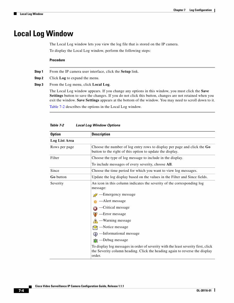
Chapter 7 Log ConfigurationLocal Log Window
Local Log WindowThe Local Log window lets you view the log file that is stored on the IP camera.
To display the Local Log window, perform the following steps:
Procedure
Step 1 From the IP camera user interface, click the Setup link.
Step 2 Click Log to expand the menu.
Step 3 From the Log menu, click Local Log.
The Local Log window appears. If you change any options in this window, you must click the Save Settings button to save the changes. If you do not click this button, changes are not retained when you exit the window. Save Settings appears at the bottom of the window. You may need to scroll down to it.
Table 7-2 describes the options in the Local Log window.
Table 7-2 Local Log Window Options
Option Description
Log List Area
Rows per page Choose the number of log entry rows to display per page and click the Go button to the right of this option to update the display.
Filter Choose the type of log message to include in the display.
To include messages of every severity, choose All.
Since Choose the time period for which you want to view log messages.
Go button Update the log display based on the values in the Filter and Since fields.
Severity An icon in this column indicates the severity of the corresponding log message:
—Emergency message
—Alert message
—Critical message
—Error message
—Warning message
—Notice message
—Informational message
—Debug message
To display log messages in order of severity with the least severity first, click the Severity column heading. Click the heading again to reverse the display order.
7-4Cisco Video Surveillance IP Camera Configuration Guide, Release 1.1.1
OL-28116-01
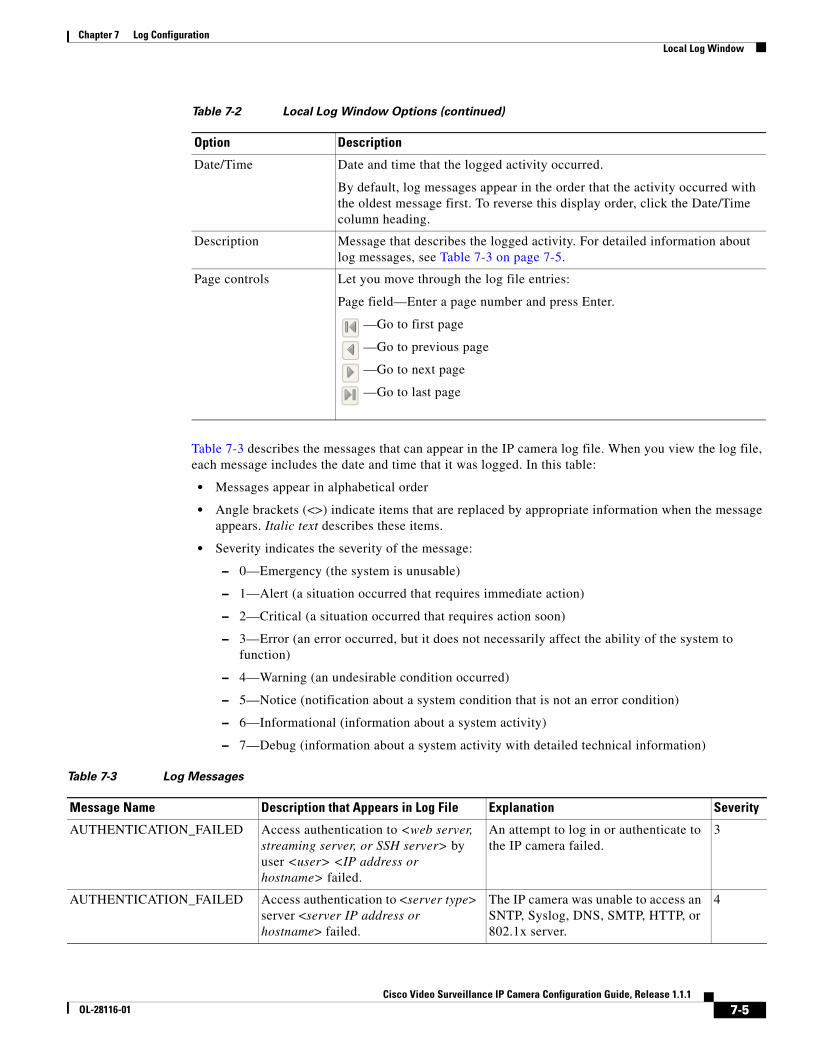
Chapter 7 Log ConfigurationLocal Log Window
Table 7-3 describes the messages that can appear in the IP camera log file. When you view the log file, each message includes the date and time that it was logged. In this table:
• Messages appear in alphabetical order
• Angle brackets (<>) indicate items that are replaced by appropriate information when the message appears. Italic text describes these items.
• Severity indicates the severity of the message:
– 0—Emergency (the system is unusable)
– 1—Alert (a situation occurred that requires immediate action)
– 2—Critical (a situation occurred that requires action soon)
– 3—Error (an error occurred, but it does not necessarily affect the ability of the system to function)
– 4—Warning (an undesirable condition occurred)
– 5—Notice (notification about a system condition that is not an error condition)
– 6—Informational (information about a system activity)
– 7—Debug (information about a system activity with detailed technical information)
Date/Time Date and time that the logged activity occurred.
By default, log messages appear in the order that the activity occurred with the oldest message first. To reverse this display order, click the Date/Time column heading.
Description Message that describes the logged activity. For detailed information about log messages, see Table 7-3 on page 7-5.
Page controls Let you move through the log file entries:
Page field—Enter a page number and press Enter.
—Go to first page
—Go to previous page
—Go to next page
—Go to last page
Table 7-2 Local Log Window Options (continued)
Option Description
Table 7-3 Log Messages
Message Name Description that Appears in Log File Explanation Severity
AUTHENTICATION_FAILED Access authentication to <web server, streaming server, or SSH server> by user <user> <IP address or hostname> failed.
An attempt to log in or authenticate to the IP camera failed.
3
AUTHENTICATION_FAILED Access authentication to <server type> server <server IP address or hostname> failed.
The IP camera was unable to access an SNTP, Syslog, DNS, SMTP, HTTP, or 802.1x server.
4
7-5Cisco Video Surveillance IP Camera Configuration Guide, Release 1.1.1
OL-28116-01
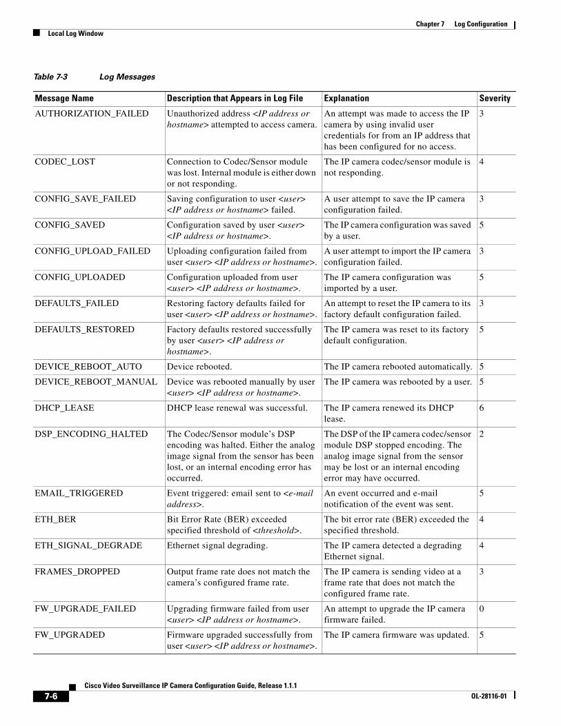
Chapter 7 Log ConfigurationLocal Log Window
AUTHORIZATION_FAILED Unauthorized address <IP address or hostname> attempted to access camera.
An attempt was made to access the IP camera by using invalid user credentials for from an IP address that has been configured for no access.
3
CODEC_LOST Connection to Codec/Sensor module was lost. Internal module is either down or not responding.
The IP camera codec/sensor module is not responding.
4
CONFIG_SAVE_FAILED Saving configuration to user <user> <IP address or hostname> failed.
A user attempt to save the IP camera configuration failed.
3
CONFIG_SAVED Configuration saved by user <user> <IP address or hostname>.
The IP camera configuration was saved by a user.
5
CONFIG_UPLOAD_FAILED Uploading configuration failed from user <user> <IP address or hostname>.
A user attempt to import the IP camera configuration failed.
3
CONFIG_UPLOADED Configuration uploaded from user <user> <IP address or hostname>.
The IP camera configuration was imported by a user.
5
DEFAULTS_FAILED Restoring factory defaults failed for user <user> <IP address or hostname>.
An attempt to reset the IP camera to its factory default configuration failed.
3
DEFAULTS_RESTORED Factory defaults restored successfully by user <user> <IP address or hostname>.
The IP camera was reset to its factory default configuration.
5
DEVICE_REBOOT_AUTO Device rebooted. The IP camera rebooted automatically. 5
DEVICE_REBOOT_MANUAL Device was rebooted manually by user <user> <IP address or hostname>.
The IP camera was rebooted by a user. 5
DHCP_LEASE DHCP lease renewal was successful. The IP camera renewed its DHCP lease.
6
DSP_ENCODING_HALTED The Codec/Sensor module’s DSP encoding was halted. Either the analog image signal from the sensor has been lost, or an internal encoding error has occurred.
The DSP of the IP camera codec/sensor module DSP stopped encoding. The analog image signal from the sensor may be lost or an internal encoding error may have occurred.
2
EMAIL_TRIGGERED Event triggered: email sent to <e-mail address>.
An event occurred and e-mail notification of the event was sent.
5
ETH_BER Bit Error Rate (BER) exceeded specified threshold of <threshold>.
The bit error rate (BER) exceeded the specified threshold.
4
ETH_SIGNAL_DEGRADE Ethernet signal degrading. The IP camera detected a degrading Ethernet signal.
4
FRAMES_DROPPED Output frame rate does not match the camera’s configured frame rate.
The IP camera is sending video at a frame rate that does not match the configured frame rate.
3
FW_UPGRADE_FAILED Upgrading firmware failed from user <user> <IP address or hostname>.
An attempt to upgrade the IP camera firmware failed.
0
FW_UPGRADED Firmware upgraded successfully from user <user> <IP address or hostname>.
The IP camera firmware was updated. 5
Table 7-3 Log Messages
Message Name Description that Appears in Log File Explanation Severity
7-6Cisco Video Surveillance IP Camera Configuration Guide, Release 1.1.1
OL-28116-01
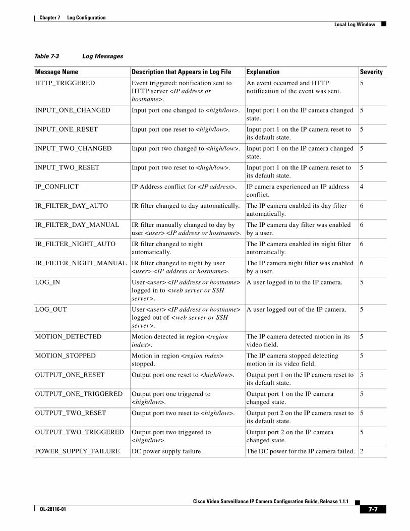
Chapter 7 Log ConfigurationLocal Log Window
HTTP_TRIGGERED Event triggered: notification sent to HTTP server <IP address or hostname>.
An event occurred and HTTP notification of the event was sent.
5
INPUT_ONE_CHANGED Input port one changed to <high/low>. Input port 1 on the IP camera changed state.
5
INPUT_ONE_RESET Input port one reset to <high/low>. Input port 1 on the IP camera reset to its default state.
5
INPUT_TWO_CHANGED Input port two changed to <high/low>. Input port 1 on the IP camera changed state.
5
INPUT_TWO_RESET Input port two reset to <high/low>. Input port 1 on the IP camera reset to its default state.
5
IP_CONFLICT IP Address conflict for <IP address>. IP camera experienced an IP address conflict.
4
IR_FILTER_DAY_AUTO IR filter changed to day automatically. The IP camera enabled its day filter automatically.
6
IR_FILTER_DAY_MANUAL IR filter manually changed to day by user <user> <IP address or hostname>.
The IP camera day filter was enabled by a user.
6
IR_FILTER_NIGHT_AUTO IR filter changed to night automatically.
The IP camera enabled its night filter automatically.
6
IR_FILTER_NIGHT_MANUAL IR filter changed to night by user <user> <IP address or hostname>.
The IP camera night filter was enabled by a user.
6
LOG_IN User <user> <IP address or hostname> logged in to <web server or SSH server>.
A user logged in to the IP camera. 5
LOG_OUT User <user> <IP address or hostname> logged out of <web server or SSH server>.
A user logged out of the IP camera. 5
MOTION_DETECTED Motion detected in region <region index>.
The IP camera detected motion in its video field.
5
MOTION_STOPPED Motion in region <region index> stopped.
The IP camera stopped detecting motion in its video field.
5
OUTPUT_ONE_RESET Output port one reset to <high/low>. Output port 1 on the IP camera reset to its default state.
5
OUTPUT_ONE_TRIGGERED Output port one triggered to <high/low>.
Output port 1 on the IP camera changed state.
5
OUTPUT_TWO_RESET Output port two reset to <high/low>. Output port 2 on the IP camera reset to its default state.
5
OUTPUT_TWO_TRIGGERED Output port two triggered to <high/low>.
Output port 2 on the IP camera changed state.
5
POWER_SUPPLY_FAILURE DC power supply failure. The DC power for the IP camera failed. 2
Table 7-3 Log Messages
Message Name Description that Appears in Log File Explanation Severity
7-7Cisco Video Surveillance IP Camera Configuration Guide, Release 1.1.1
OL-28116-01

Chapter 7 Log ConfigurationLocal Log Window
SERVER_CONTACTED Communication established with <server type> server <server or IP address>.
The IP camera established communication with an SNTP, DHCP, Syslog, DNS, SMTP, HTTP, or 802.1x server.
6
SERVER_LOST Communication lost with <server type> server <server or IP address>.
The IP camera lost communication with an SNTP, DHCP, Syslog, DNS, SMTP, HTTP, or 802.1x server.
4
SERVER_UNREACHABLE Failed to contact <server type> server <server or IP address>.
The IP camera was unable to contact an SNTP, DHCP, Syslog, DNS, SMTP, HTTP, or 802.1x server or a gateway.
4
START_STREAM Channel <channel ID> started streaming to user <user> <IP address or hostname>.
The IP camera began streaming video to a user device.
6
STOP_STREAM Channel <channel ID> stopped streaming to user <user> <IP address or hostname>.
The IP camera stopped streaming video to a user device.
6
TEMP_THRESHOLD_T1 Current temperature, <temperature>, <exceeds/is below> <high temperature/ low_temperature> threshold.
The internal temperature of the IP camera is lower than 59°F (15°C) or higher than 149°F (65°C).
2
TEMP_THRESHOLD_T2 Current temperature, <temperature>, <exceeds/is below> <high temperature/ low_temperature> threshold.
The internal temperature of the IP camera is lower than 32°F (0°C) or higher than 176°F (80°C).
4
TEMP_THRESHOLD_T3 Current temperature, <temperature>, <exceeds/is below> <high temperature/ low_temperature> threshold.
The internal temperature of the IP camera is lower than 5°F (–15°C) or higher than 194°F (90°C).
5
TIME_DST_SWITCH Time switched to Daylight Savings time with an offset of <offset> minutes.
The IP camera internal clock switched to daylight saving time.
6
TIME_REG_SWITCH Time switched from Daylight Savings time with an offset of <offset> minutes.
The IP camera internal clock switched to standard time.
6
UNEXPECTED_EXCEPTION Unexpected exception occurred. Could not <read/write> <to/from> repository by user <user> <IP address or hostname>.
IP camera could not read or write information to its internal repository.
2
Table 7-3 Log Messages
Message Name Description that Appears in Log File Explanation Severity
7-8Cisco Video Surveillance IP Camera Configuration Guide, Release 1.1.1
OL-28116-01
Cisco Video SurveilOL-28116-01
I N D E X
A
About link 1-4
Account Initialization window
options 6-2
overview 6-1
action
triggered by event 4-9
ActiveX controls 1-4
Administration windows 6-1, 7-1
audio
settings 4-4
B
backing up, configuration of IP camera 6-4
Basic Settings window
options 5-2
overview 5-1
bit rate, of video 4-4
Bonjour, enabling on camera 5-6
brightness 3-2
C
Camera Settings window
options 4-5
overview 4-5
Camera Video & Control window
accessing 3-1
description 1-4
displaying 1-4
CDP (Cisco Discovery Protocol), enabling on camera 5-6
configuration windows
accessing 1-2
Account Initialization window 6-1
Administration windows 6-1
Basic Settings window 5-1
Camera Settings window 4-5
Device Processes window 6-7
Discovery Settings window 5-5
Event Notification window 4-9
Feature Setup windows 4-1
Firmware Settings window 6-6
IO Ports Settings window 4-8
IP Addressing window 5-2
IP Filter Settings window 5-6
Local Log window 7-4
Log Setup Settings window 7-1
Log windows 7-1
Maintenance Settings window 6-4
Network Setup windows 5-1
Password Complexity window 6-8
QoS Settings window 5-7
Streaming Settings window 4-1
Time Settings window 5-4
User Settings window 6-3
Video Overlay Settings window 4-7
connecting, to the IP camera
after the first time 1-2
for the first time 2-1
PC requirements for 1-2, 2-1
secure connection 1-3
contrast 3-2
IN-1lance IP Camera Configuration Guide, Release 1.1.1
Index
D
date and time
configuring manually 5-4
updating through NTP server 5-4
day
filter 4-5
mode 4-5
daylight saving time, adjustment for 5-4
Device Processes window
options 6-8
overview 6-7
DHCP, obtaining IP address through 2-1, 5-3
Differentiated Services (DiffServ) 5-8
Discovery Settings window
options 5-6
overview 5-5
DNS server
primary 5-3
secondary 5-3
dual streaming 4-1
E
e-mail notification
configuring 4-12
From field 4-13
recipients 4-13
event
actions
HTTP notification 4-9
output port state change 4-10
syslog server message 4-10
overview 4-9
trigger types 4-11
Event Notification window
options 4-11
overview 4-9
IN-2Cisco Video Surveillance IP Camera Configuration Guide, Release
F
factory default configurations, resetting 6-5
factory default configurations, restoring 6-5
Feature Setup windows 4-1
firmware
upgrading 6-6, 6-7
version in IP camera 6-7
Firmware Settings window
options 6-7
overview 6-6
focus/zoom
accessing controls 3-5
controls 3-5
FTP notification
configuring 4-14
G
gateway, for IP camera 5-3
H
help, for IP camera windows 1-4
Home window
accessing 1-2
description 1-3, 1-4
displaying 1-4
HTTP
accessing camera through 1-3
allowing access through 2-2, 6-2
default port 6-2
port 6-2
HTTPS
accessing camera through 1-3
allowing access through 6-2
default port 6-2
port 6-2
1.1.1OL-28116-01
Index
I
input ports
state change 4-9
IO Ports Settings window
options 4-9
overview 4-8
IP address
controlling access by 5-6
default for IP camera 1-2, 1-3, 2-1
fixed 5-3
obtaining from DCHP server 2-1
obtaining through DHCP 5-3
static 5-3
IP Addressing window
options 5-3
overview 5-2
IP camera
accessing through a web browser 1-2, 2-1
connecting to after the first time 1-2
connecting to for the first time 2-1
controlling access to 5-6
day mode 4-5
logging in to 1-3
logging out of 1-4
MAC address 6-7
name 5-2
night mode 4-5
overview 1-1
panning 3-3
rebooting 6-5
restarting 6-5
restoring factory default configurations 6-5
tilting 3-3
time zone 5-4
windows 1-2, 1-4
IP Filter Settings window
options 5-6
overview 5-6
Cisco VideOL-28116-01
L
live video
viewing
through home window 3-1
through third-party device or software 3-1
See also video
Local Log window
options 7-4
overview 7-4
log file
sending to Syslog server 7-2
storage of 7-1
viewing 7-4
log in, to IP camera 1-3
log out, of IP camera 1-4
Log Setup Settings window
options 7-2
overview 7-1
M
MAC address, of IP camera 6-7
Maintenance Settings window
options 6-5
overview 6-4
motion detection
accessing controls 3-3
enabling 3-4
sensitivity 3-4, 3-5
threshold 3-4, 3-5
Motion detection controls 3-4
multicast
address 4-3
enabling 4-3
port 4-3, 4-4
IN-3o Surveillance IP Camera Configuration Guide, Release 1.1.1
Index
N
name, of IP camera 5-2, 6-7
Network Setup windows 5-1
night
filter 4-5
mode 4-5
O
output ports
power on state 4-9
P
panning 3-3
password
complexity 6-8
configuring requirements for 6-8
for primary SMTP server 4-13
for secondary SMTP server 4-13
for user 6-4
hardening 6-8
requirements for 2-2, 6-4
Password Complexity window
options 6-9
overview 6-8
port number 1-2
processes
descriptions 6-8
stopping 6-7
Q
QoS Settings window
options 5-7
overview 5-7
quality of service 5-7
IN-4Cisco Video Surveillance IP Camera Configuration Guide, Release
R
rebooting, IP camera 6-5
Refresh link 1-4
resetting, factory default configurations 6-5
restarting, IP camera 6-5
restoring, factory default configurations 6-5
S
saturation 3-2
secure connection 1-3
security
controlling processes 6-7
password hardening 6-8
stopping processes 6-7
sensitivity, for motion detection 3-4, 3-5
Setup window
description 1-4
displaying 1-4
sharpness 3-2
SSH
allowing access through 6-2
alternative port 6-2
default port 6-2
Streaming Settings window
options 4-3
overview 4-1
subnet mask, of IP camera 5-3
Syslog server 7-2
T
text overlay, on video 4-8
threshold, for motion detection 3-4, 3-5
tilting 3-3
Time Settings window
options 5-4
overview 5-4
1.1.1OL-28116-01
Index
time stamp, on video 4-8
time zone, of IP camera 5-4
trigger, for event 4-11
U
user, password 6-4
user name, requirements for 6-4
User Settings window
options 6-4
overview 6-3
V
video
bit rate 4-4
primary stream 4-1
quality 4-4
secondary stream 4-1
text overlay 4-8
time stamp on 4-8
viewing live
through Home window 3-1
through third-party device or software 3-1
See also live video
video codec
controls in Camera Video/Control window 3-1
display in Streaming Settings window 4-4
video image
controls in Camera Video/Control window 3-2
optimizing for lighting condition 4-5
Video Overlay Settings window
options 4-8
overview 4-7
video resolution
configuration guidelines 4-1
controls in Camera Video/Control window 3-2
View Video link 1-4
Cisco VideOL-28116-01
Z
zoom
accessing controls 3-5
zoom controls 3-5
IN-5o Surveillance IP Camera Configuration Guide, Release 1.1.1

Index
IN-6Cisco Video Surveillance IP Camera Configuration Guide, Release
1.1.1OL-28116-01