Embed Size (px)
Citation preview

Cisco Video Surveillance Manager Safety and Security Desktop User Guide Release 7.0
Americas HeadquartersCisco Systems, Inc.170 West Tasman DriveSan Jose, CA 95134-1706 USAhttp://www.cisco.comTel: 408 526-4000
800 553-NETS (6387)Fax: 408 527-0883
Text Part Number: OL-27379-03

THE SPECIFICATIONS AND INFORMATION REGARDING THE PRODUCTS IN THIS MANUAL ARE SUBJECT TO CHANGE WITHOUT NOTICE. ALL STATEMENTS, INFORMATION, AND RECOMMENDATIONS IN THIS MANUAL ARE BELIEVED TO BE ACCURATE BUT ARE PRESENTED WITHOUT WARRANTY OF ANY KIND, EXPRESS OR IMPLIED. USERS MUST TAKE FULL RESPONSIBILITY FOR THEIR APPLICATION OF ANY PRODUCTS.
THE SOFTWARE LICENSE AND LIMITED WARRANTY FOR THE ACCOMPANYING PRODUCT ARE SET FORTH IN THE INFORMATION PACKET THAT SHIPPED WITH THE PRODUCT AND ARE INCORPORATED HEREIN BY THIS REFERENCE. IF YOU ARE UNABLE TO LOCATE THE SOFTWARE LICENSE OR LIMITED WARRANTY, CONTACT YOUR CISCO REPRESENTATIVE FOR A COPY.
The Cisco implementation of TCP header compression is an adaptation of a program developed by the University of California, Berkeley (UCB) as part of UCB’s public domain version of the UNIX operating system. All rights reserved. Copyright © 1981, Regents of the University of California.
NOTWITHSTANDING ANY OTHER WARRANTY HEREIN, ALL DOCUMENT FILES AND SOFTWARE OF THESE SUPPLIERS ARE PROVIDED “AS IS” WITH ALL FAULTS. CISCO AND THE ABOVE-NAMED SUPPLIERS DISCLAIM ALL WARRANTIES, EXPRESSED OR IMPLIED, INCLUDING, WITHOUT LIMITATION, THOSE OF MERCHANTABILITY, FITNESS FOR A PARTICULAR PURPOSE AND NONINFRINGEMENT OR ARISING FROM A COURSE OF DEALING, USAGE, OR TRADE PRACTICE.
IN NO EVENT SHALL CISCO OR ITS SUPPLIERS BE LIABLE FOR ANY INDIRECT, SPECIAL, CONSEQUENTIAL, OR INCIDENTAL DAMAGES, INCLUDING, WITHOUT LIMITATION, LOST PROFITS OR LOSS OR DAMAGE TO DATA ARISING OUT OF THE USE OR INABILITY TO USE THIS MANUAL, EVEN IF CISCO OR ITS SUPPLIERS HAVE BEEN ADVISED OF THE POSSIBILITY OF SUCH DAMAGES.
Cisco and the Cisco logo are trademarks or registered trademarks of Cisco and/or its affiliates in the U.S. and other countries. To view a list of Cisco trademarks, go to this URL: www.cisco.com/go/trademarks. Third-party trademarks mentioned are the property of their respective owners. The use of the word partner does not imply a partnership relationship between Cisco and any other company. (1110R)
Any Internet Protocol (IP) addresses and phone numbers used in this document are not intended to be actual addresses and phone numbers. Any examples, command display output, network topology diagrams, and other figures included in the document are shown for illustrative purposes only. Any use of actual IP addresses or phone numbers in illustrative content is unintentional and coincidental.
Cisco Video Surveillance Manager Safety and Security Desktop User Guide © 2012-2013 Cisco Systems, Inc. All rights reserved.
OL-27379-03
C O N T E N T S
Preface v
Overview v
Obtaining Documentation, Obtaining Support, and Security Guidelines v
C H A P T E R 1 Getting Started 1-1
Overview 1-1
Understanding the Video Viewing Options 1-4
Requirements 1-5
Installing the Application 1-6
Logging In 1-7
Changing Your Password 1-7
C H A P T E R 2 Viewing a Video Grid 2-1
Viewing Video from Specific Cameras 2-2
Viewing Camera Video in a Multi-Pane Grid 2-4
Displaying a Video Grid on a Separate Monitor 2-5
Creating a Video Wall 2-8
Configuring Unattended Workstations 2-10
C H A P T E R 3 Controlling Video Playback 3-1
Overview 3-2
Viewing Live Video 3-3
Viewing Recorded Video 3-6
Creating Video Clips 3-10
Creating a Repeat Segment 3-16
Using Record Now 3-17
Using the Pop-Up Menu 3-18
Understanding Video Pane Border Colors 3-19
Using the Smooth Video Options When Viewing Live Video 3-20
Synchronizing Video Playback in Multiple Panes 3-21
Using Pan, Tilt, and Zoom (PTZ) Controls 3-24
iiiCisco Video Surveillance Manager Safety and Security Desktop User Guide
Contents
C H A P T E R 4 Viewing Alerts 4-1
Alert Management Overview 4-2
Common Tasks 4-3
Impact of Device Location Changes on Alerts 4-4
C H A P T E R 5 Viewing Cameras and Alerts on Map 5-1
C H A P T E R 6 Editing Locations and Maps 6-1
Map Editor Overview 6-2
Editing Locations 6-3
Adding or Updating Map Images 6-5
Placing a Sub-Location on a Map 6-6
ivCisco Video Surveillance Manager Safety and Security Desktop User Guide
OL-27379-03
Preface
Revised: April 12, 2013
OverviewThis Cisco Video Surveillance Manager Safety and Security Desktop User Guide provides an overview of the desktop software used to view video from the Cisco Video Surveillance Manager (Cisco VSM).
Obtaining Documentation, Obtaining Support, and Security Guidelines
For information about obtaining documentation, submitting a service request, and gathering additional information, see the monthly What’s New in Cisco Product Documentation. This document also lists all new and revised Cisco technical documentation. It is available at:
http://www.cisco.com/en/US/docs/general/whatsnew/whatsnew.html
Subscribe to the What’s New in Cisco Product Documentation as a Really Simple Syndication (RSS) feed and set content to be delivered directly to your desktop using a reader application. The RSS feeds are a free service and Cisco currently supports RSS version 2.0.
See also the Related Documentation section.
vCisco Video Surveillance Manager Safety and Security Desktop User Guide
OL-27379-03

Preface
viCisco Video Surveillance Manager Safety and Security Desktop User Guide
OL-27379-03
Cisco Video SurveillancOL-27379-03
C H A P T E R 1
Getting StartedContents • Overview, page 1-1
• Understanding the Video Viewing Options, page 1-4
• Requirements, page 1-5
• Installing the Application, page 1-6
• Logging In, page 1-7
OverviewThe Cisco Video Surveillance Safety and Security Desktop application (Cisco SASD) allows you to monitor live and recorded video surveillance using a variety of tools. For example:
• View a list of available cameras based on the camera location.
• View the cameras and related video on a map.
• View system alerts and the camera that generated the alert.
• View multiple cameras in a grid.
• Create multiple viewing windows and drag them onto additional monitors connected to the PC workstation.
• Create Video Walls to display the same pre-defined set of viewing panes on multiple workstations.
• Use Unattended Mode to automatically open the Video Walls on workstations that do not have a mouse or keyboard.
1-1e Manager Safety and Security Desktop User Guide
Chapter 1 Getting StartedOverview
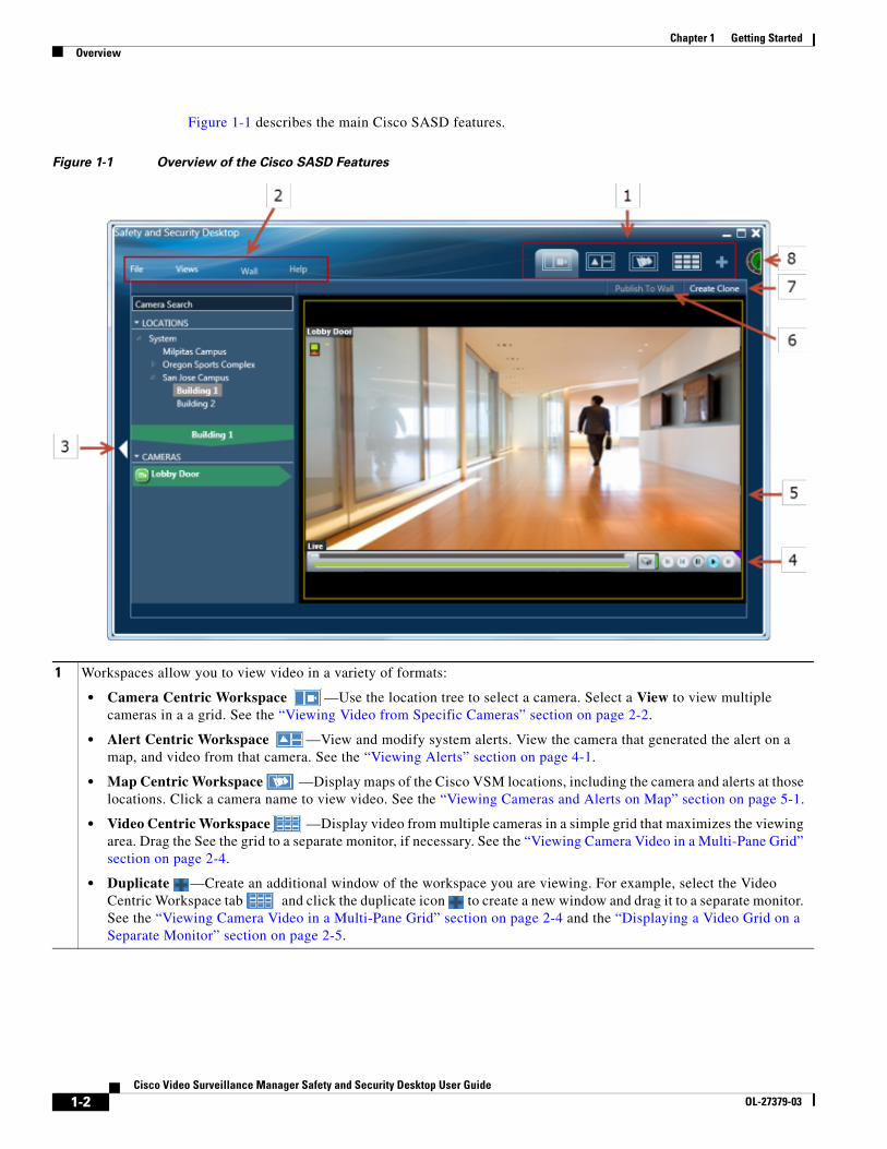
Figure 1-1 describes the main Cisco SASD features.
Figure 1-1 Overview of the Cisco SASD Features
1 Workspaces allow you to view video in a variety of formats:
• Camera Centric Workspace —Use the location tree to select a camera. Select a View to view multiple cameras in a a grid. See the “Viewing Video from Specific Cameras” section on page 2-2.
• Alert Centric Workspace —View and modify system alerts. View the camera that generated the alert on a map, and video from that camera. See the “Viewing Alerts” section on page 4-1.
• Map Centric Workspace —Display maps of the Cisco VSM locations, including the camera and alerts at those locations. Click a camera name to view video. See the “Viewing Cameras and Alerts on Map” section on page 5-1.
• Video Centric Workspace —Display video from multiple cameras in a simple grid that maximizes the viewing area. Drag the See the grid to a separate monitor, if necessary. See the “Viewing Camera Video in a Multi-Pane Grid” section on page 2-4.
• Duplicate —Create an additional window of the workspace you are viewing. For example, select the Video Centric Workspace tab and click the duplicate icon to create a new window and drag it to a separate monitor. See the “Viewing Camera Video in a Multi-Pane Grid” section on page 2-4 and the “Displaying a Video Grid on a Separate Monitor” section on page 2-5.
1-2Cisco Video Surveillance Manager Safety and Security Desktop User Guide
OL-27379-03
Chapter 1 Getting StartedOverview
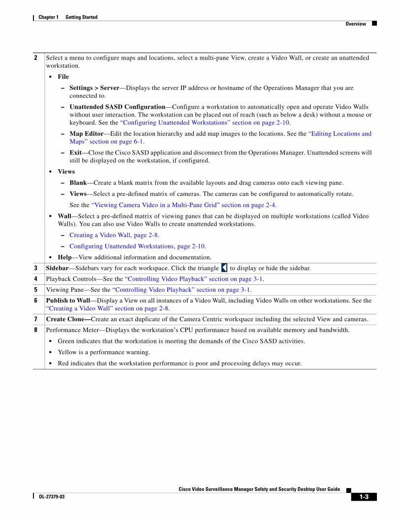
2 Select a menu to configure maps and locations, select a multi-pane View, create a Video Wall, or create an unattended workstation.
• File
– Settings > Server—Displays the server IP address or hostname of the Operations Manager that you are connected to.
– Unattended SASD Configuration—Configure a workstation to automatically open and operate Video Walls without user interaction. The workstation can be placed out of reach (such as below a desk) without a mouse or keyboard. See the “Configuring Unattended Workstations” section on page 2-10.
– Map Editor—Edit the location hierarchy and add map images to the locations. See the “Editing Locations and Maps” section on page 6-1.
– Exit—Close the Cisco SASD application and disconnect from the Operations Manager. Unattended screens will still be displayed on the workstation, if configured.
• Views
– Blank—Create a blank matrix from the available layouts and drag cameras onto each viewing pane.
– Views—Select a pre-defined matrix of cameras. The cameras can be configured to automatically rotate.
See the “Viewing Camera Video in a Multi-Pane Grid” section on page 2-4.
• Wall—Select a pre-defined matrix of viewing panes that can be displayed on multiple workstations (called Video Walls). You can also use Video Walls to create unattended workstations.
– Creating a Video Wall, page 2-8.
– Configuring Unattended Workstations, page 2-10.
• Help—View additional information and documentation.
3 Sidebar—Sidebars vary for each workspace. Click the triangle to display or hide the sidebar.
4 Playback Controls—See the “Controlling Video Playback” section on page 3-1.
5 Viewing Pane—See the “Controlling Video Playback” section on page 3-1.
6 Publish to Wall—Display a View on all instances of a Video Wall, including Video Walls on other workstations. See the “Creating a Video Wall” section on page 2-8.
7 Create Clone—Create an exact duplicate of the Camera Centric workspace including the selected View and cameras.
8 Performance Meter—Displays the workstation’s CPU performance based on available memory and bandwidth.
• Green indicates that the workstation is meeting the demands of the Cisco SASD activities.
• Yellow is a performance warning.
• Red indicates that the workstation performance is poor and processing delays may occur.
1-3Cisco Video Surveillance Manager Safety and Security Desktop User Guide
OL-27379-03
Chapter 1 Getting StartedUnderstanding the Video Viewing Options
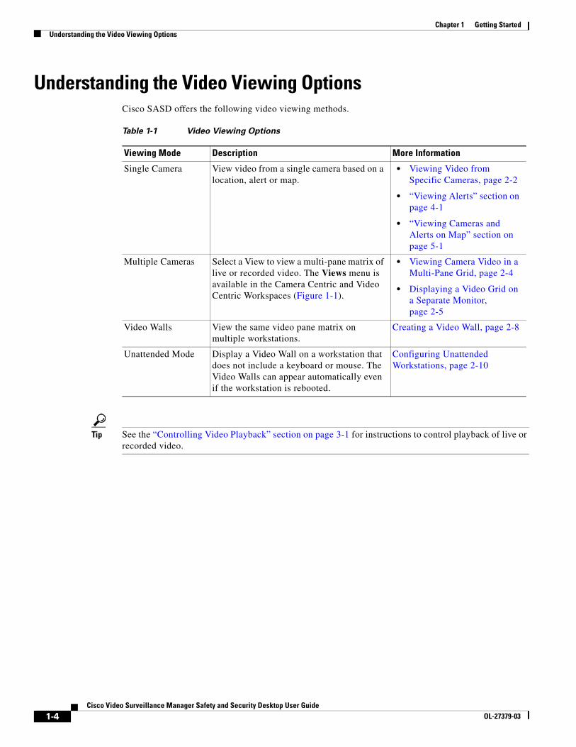
Understanding the Video Viewing OptionsCisco SASD offers the following video viewing methods.
Table 1-1 Video Viewing Options
Viewing Mode Description More Information
Single Camera View video from a single camera based on a location, alert or map.
• Viewing Video from Specific Cameras, page 2-2
• “Viewing Alerts” section on page 4-1
• “Viewing Cameras and Alerts on Map” section on page 5-1
Multiple Cameras Select a View to view a multi-pane matrix of live or recorded video. The Views menu is available in the Camera Centric and Video Centric Workspaces (Figure 1-1).
• Viewing Camera Video in a Multi-Pane Grid, page 2-4
• Displaying a Video Grid on a Separate Monitor, page 2-5
Video Walls View the same video pane matrix on multiple workstations.
Creating a Video Wall, page 2-8
Unattended Mode Display a Video Wall on a workstation that does not include a keyboard or mouse. The Video Walls can appear automatically even if the workstation is rebooted.
Configuring Unattended Workstations, page 2-10
Tip See the “Controlling Video Playback” section on page 3-1 for instructions to control playback of live or recorded video.
1-4Cisco Video Surveillance Manager Safety and Security Desktop User Guide
OL-27379-03
Chapter 1 Getting StartedRequirements
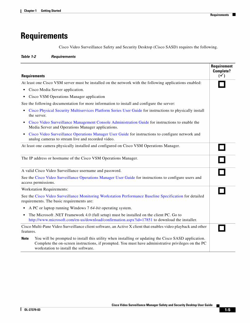
Requirements Cisco Video Surveillance Safety and Security Desktop (Cisco SASD) requires the following.
Table 1-2 Requirements
Requirements
Requirement Complete?
( )
At least one Cisco VSM server must be installed on the network with the following applications enabled:
• Cisco Media Server application.
• Cisco VSM Operations Manager application
See the following documentation for more information to install and configure the server:
• Cisco Physical Security Multiservices Platform Series User Guide for instructions to physically install the server.
• Cisco Video Surveillance Management Console Administration Guide for instructions to enable the Media Server and Operations Manager applications.
• Cisco Video Surveillance Operations Manager User Guide for instructions to configure network and analog cameras to stream live and recorded video.
At least one camera physically installed and configured on Cisco VSM Operations Manager.
The IP address or hostname of the Cisco VSM Operations Manager.
A valid Cisco Video Surveillance username and password.
See the Cisco Video Surveillance Operations Manager User Guide for instructions to configure users and access permissions.
Workstation Requirements:
See the Cisco Video Surveillance Monitoring Workstation Performance Baseline Specification for detailed requirements. The basic requirements are:
• A PC or laptop running Windows 7 64-bit operating system.
• The Microsoft .NET Framework 4.0 (full setup) must be installed on the client PC. Go to http://www.microsoft.com/en-us/download/confirmation.aspx?id=17851 to download the installer.
Cisco Multi-Pane Video Surveillance client software, an Active X client that enables video playback and other features.
Note You will be prompted to install this utility when installing or updating the Cisco SASD application. Complete the on-screen instructions, if prompted. You must have administrative privileges on the PC workstation to install the software.
1-5Cisco Video Surveillance Manager Safety and Security Desktop User Guide
OL-27379-03
Chapter 1 Getting StartedInstalling the Application
Installing the ApplicationProcedure
Step 1 Verify that the system and workstation requirements are met, as described in the “Requirements” section on page 1-5.
Step 2 Install the Microsoft .NET Framework 4.0, if necessary.
Go to http://www.microsoft.com/en-us/download/confirmation.aspx?id=17851 to download the installer.
Step 3 Log in to the Cisco VSM browser-based Operations Manager.
a. Launch the 32-bit version of Internet Explorer 8 on your Windows 7 computer.
b. Enter the URL for the Cisco VSM Operations Manager.
c. Enter your username and password.
d. Choose the default “localhost” if your account was created using the Operations Manager. Select a Domain if you are a user from an external database (Active Directory LDAP domain).
e. Enter a new password if prompted.
f. You must enter a new username the first time you log in, or when your password periodically expires.
Step 4 Select the Operations tab.
Step 5 Click Safety and Security Desktop (under the Software heading).
Step 6 Follow the onscreen instructions to complete the installation.
Tip • To access the application on your workstation, double-click the Safety And Security Desktop icon on your desktop, or go to Start > All Programs > Cisco > Cisco Safety And Security Desktop.
• You can save the installer file and use it to install the application on multiple workstations, if necessary. Users must have a valid Cisco VSM username and password to access the system.
• An error appears if the Microsoft .NET Framework 4.0 is not installed. Go to http://www.microsoft.com/en-us/download/confirmation.aspx?id=17851 to download the installer, then repeat this procedure.
• If prompted, complete the on-screen instructions to install or upgrade the Cisco Multi-Pane Video Surveillance client software on your computer. This application is an Active X client that enables video playback and other features. Video will not play unless the Cisco Multi-Pane client software is correctly installed. You must have administrative privileges on the PC workstation to install the software.
1-6Cisco Video Surveillance Manager Safety and Security Desktop User Guide
OL-27379-03
Chapter 1 Getting StartedLogging In
Logging InProcedure
Step 1 Double-click the Safety And Security Desktop shortcut on your desktop, or select Start Menu > Programs > Cisco Safety And Security Desktop.
Step 2 Enter the following login information:
• Server—The IP address or hostname of the Cisco VSM Operations Manager.
• Domain—Select “localhost” if your account was created using Cisco VSM, or select another option if logging in from an external database (Active Directory LDAP domain).
• Username—Enter the username provided by your system administrator.
• Password—Enter the password provided by your system administrator.
Note You will be prompted to change your password the first time you log on, or when your password expires. The first-time login password can only be changed by the Operations Manager administrator.
Changing Your PasswordTo change your password, log on to the browser-based Cisco VSM Operations Manager and click on your username.
Step 1 Launch a web-browser (such as the 32-bit Internet Explorer (IE) 8 web browser).
Step 2 Enter the same IP address/hostname used to access the Cisco SASD.
Step 3 Enter the same username and password used to access the Cisco SASD.
Step 4 Click on your username in the upper right corner of the Cisco VSM Operations Manager.
Step 5 Enter and reenter your new password.
1-7Cisco Video Surveillance Manager Safety and Security Desktop User Guide
OL-27379-03

Chapter 1 Getting StartedLogging In
1-8Cisco Video Surveillance Manager Safety and Security Desktop User Guide
OL-27379-03
Cisco Video SurveillancOL-27379-03
C H A P T E R 2
Viewing a Video GridTo view video from multiple cameras in a grid layout, refer to the following topics.
Contents
• Viewing Video from Specific Cameras, page 2-2
• Viewing Camera Video in a Multi-Pane Grid, page 2-4
• Displaying a Video Grid on a Separate Monitor, page 2-5
• Creating a Video Wall, page 2-8
• Configuring Unattended Workstations, page 2-10
2-1e Manager Safety and Security Desktop User Guide
Chapter 2 Viewing a Video GridViewing Video from Specific Cameras
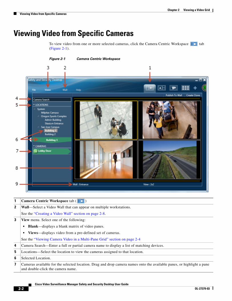
Viewing Video from Specific Cameras To view video from one or more selected cameras, click the Camera Centric Workspace tab (Figure 2-1).
Figure 2-1 Camera Centric Workspace
1 Camera Centric Workspace tab ( )
2 Wall—Select a Video Wall that can appear on multiple workstations.
See the “Creating a Video Wall” section on page 2-8.
3 View menu. Select one of the following:
• Blank—displays a blank matrix of video panes.
• Views—displays video from a pre-defined set of cameras.
See the “Viewing Camera Video in a Multi-Pane Grid” section on page 2-4
4 Camera Search—Enter a full or partial camera name to display a list of matching devices.
5 Locations—Select the location to view the cameras assigned to that location.
6 Selected Location.
7 Cameras available for the selected location. Drag and drop camera names onto the available panes, or highlight a pane and double-click the camera name.
2-2Cisco Video Surveillance Manager Safety and Security Desktop User Guide
OL-27379-03
Chapter 2 Viewing a Video GridViewing Video from Specific Cameras
Procedure
Step 1 Select the Camera Centric Workspace tab .
Step 2 Click the Views menu and select one of the following options:
• Blank—displays a blank matrix of video panes.
• Views—displays video from a pre-defined set of cameras.
Step 3 (Optional) Select a video source (camera) for each pane:
a. Search for a camera name or select a location.
b. Drag-and-drop camera names onto the available viewing panes (you can also highlight a pane and double-click the camera name).
Step 4 Use the video playback controls as described in the “Controlling Video Playback” section on page 3-1.
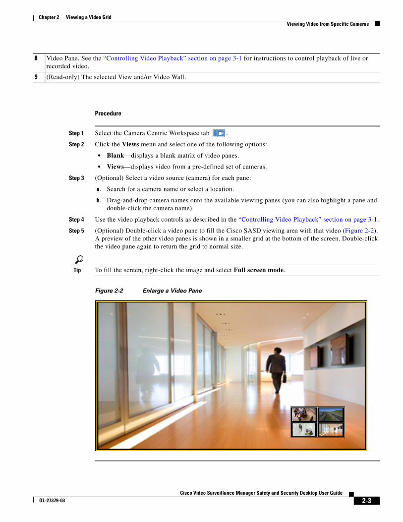
Step 5 (Optional) Double-click a video pane to fill the Cisco SASD viewing area with that video (Figure 2-2). A preview of the other video panes is shown in a smaller grid at the bottom of the screen. Double-click the video pane again to return the grid to normal size.
Tip To fill the screen, right-click the image and select Full screen mode.
Figure 2-2 Enlarge a Video Pane
8 Video Pane. See the “Controlling Video Playback” section on page 3-1 for instructions to control playback of live or recorded video.
9 (Read-only) The selected View and/or Video Wall.
2-3Cisco Video Surveillance Manager Safety and Security Desktop User Guide
OL-27379-03
Chapter 2 Viewing a Video GridViewing Camera Video in a Multi-Pane Grid
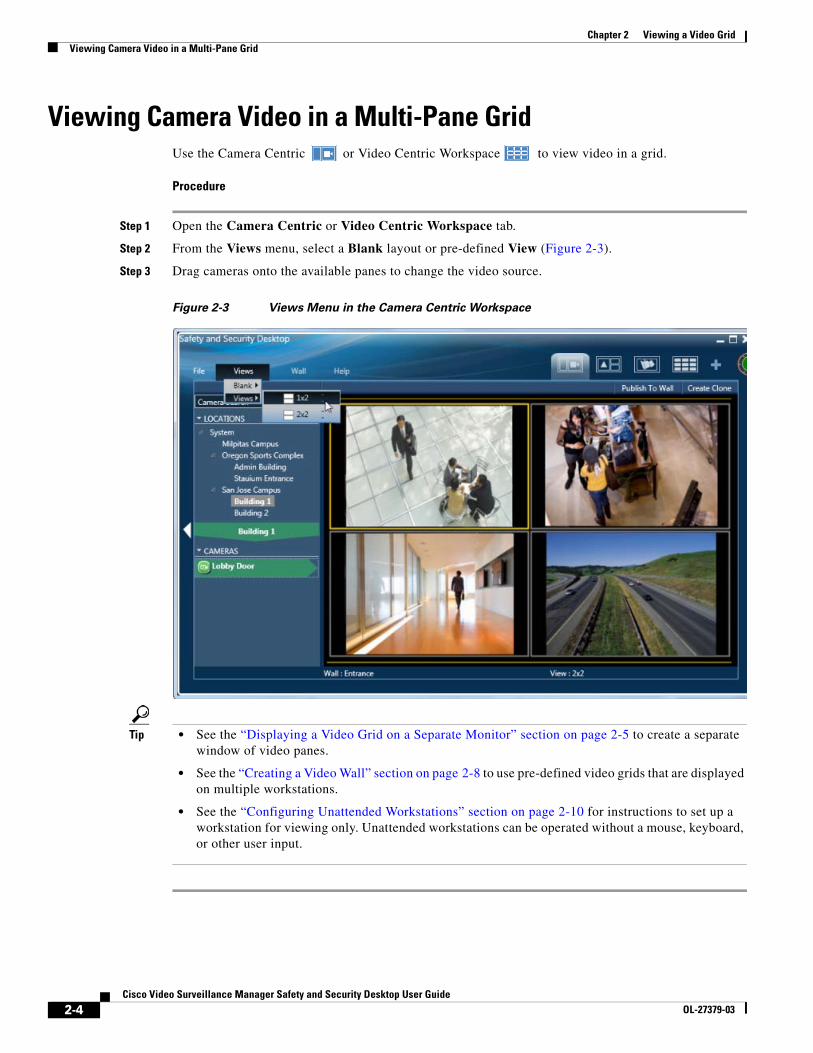
Viewing Camera Video in a Multi-Pane GridUse the Camera Centric or Video Centric Workspace to view video in a grid.
Procedure
Step 1 Open the Camera Centric or Video Centric Workspace tab.
Step 2 From the Views menu, select a Blank layout or pre-defined View (Figure 2-3).
Step 3 Drag cameras onto the available panes to change the video source.
Figure 2-3 Views Menu in the Camera Centric Workspace
Tip • See the “Displaying a Video Grid on a Separate Monitor” section on page 2-5 to create a separate window of video panes.
• See the “Creating a Video Wall” section on page 2-8 to use pre-defined video grids that are displayed on multiple workstations.
• See the “Configuring Unattended Workstations” section on page 2-10 for instructions to set up a workstation for viewing only. Unattended workstations can be operated without a mouse, keyboard, or other user input.
2-4Cisco Video Surveillance Manager Safety and Security Desktop User Guide
OL-27379-03
Chapter 2 Viewing a Video GridDisplaying a Video Grid on a Separate Monitor
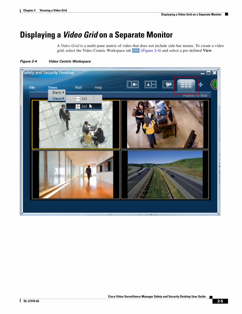
Displaying a Video Grid on a Separate MonitorA Video Grid is a multi-pane matrix of video that does not include side-bar menus. To create a video grid, select the Video Centric Workspace tab (Figure 2-4) and select a pre-defined View.
Figure 2-4 Video Centric Workspace
2-5Cisco Video Surveillance Manager Safety and Security Desktop User Guide
OL-27379-03
Chapter 2 Viewing a Video GridDisplaying a Video Grid on a Separate Monitor
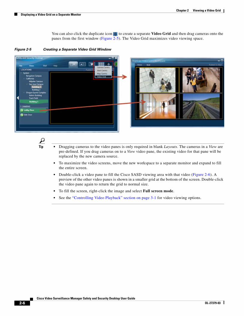
You can also click the duplicate icon to create a separate Video Grid and then drag cameras onto the panes from the first window (Figure 2-5). The Video Grid maximizes video viewing space.
Figure 2-5 Creating a Separate Video Grid Window
Tip • Dragging cameras to the video panes is only required in blank Layouts. The cameras in a View are pre-defined. If you drag cameras on to a View video pane, the existing video for that pane will be replaced by the new camera source.
• To maximize the video screens, move the new workspace to a separate monitor and expand to fill the entire screen.
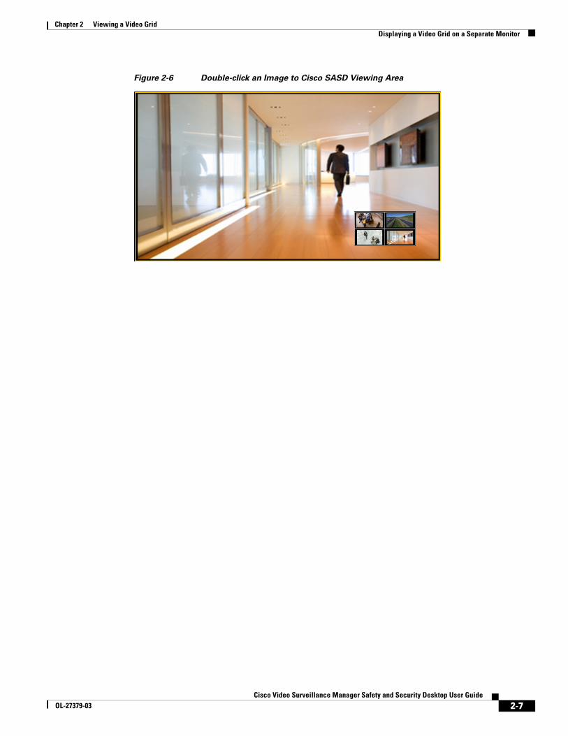
• Double-click a video pane to fill the Cisco SASD viewing area with that video (Figure 2-6). A preview of the other video panes is shown in a smaller grid at the bottom of the screen. Double-click the video pane again to return the grid to normal size.
• To fill the screen, right-click the image and select Full screen mode.
• See the “Controlling Video Playback” section on page 3-1 for video viewing options.
2-6Cisco Video Surveillance Manager Safety and Security Desktop User Guide
OL-27379-03
Chapter 2 Viewing a Video GridDisplaying a Video Grid on a Separate Monitor
Figure 2-6 Double-click an Image to Cisco SASD Viewing Area
2-7Cisco Video Surveillance Manager Safety and Security Desktop User Guide
OL-27379-03
Chapter 2 Viewing a Video GridCreating a Video Wall
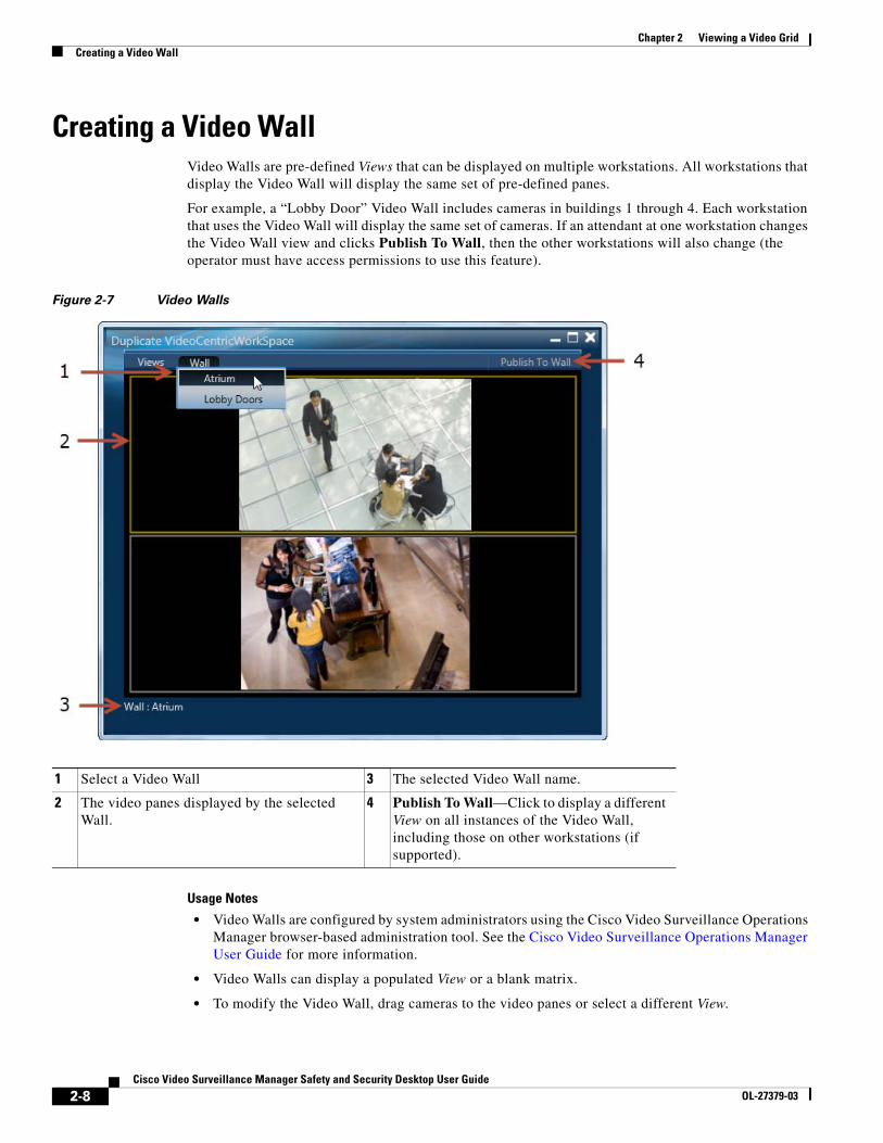
Creating a Video WallVideo Walls are pre-defined Views that can be displayed on multiple workstations. All workstations that display the Video Wall will display the same set of pre-defined panes.
For example, a “Lobby Door” Video Wall includes cameras in buildings 1 through 4. Each workstation that uses the Video Wall will display the same set of cameras. If an attendant at one workstation changes the Video Wall view and clicks Publish To Wall, then the other workstations will also change (the operator must have access permissions to use this feature).
Figure 2-7 Video Walls
1 Select a Video Wall 3 The selected Video Wall name.
2 The video panes displayed by the selected Wall.
4 Publish To Wall—Click to display a different View on all instances of the Video Wall, including those on other workstations (if supported).
Usage Notes
• Video Walls are configured by system administrators using the Cisco Video Surveillance Operations Manager browser-based administration tool. See the Cisco Video Surveillance Operations Manager User Guide for more information.
• Video Walls can display a populated View or a blank matrix.
• To modify the Video Wall, drag cameras to the video panes or select a different View.
2-8Cisco Video Surveillance Manager Safety and Security Desktop User Guide
OL-27379-03
Chapter 2 Viewing a Video GridCreating a Video Wall
• To display a different view on all other workstations that display the Video Wall, select a new View and click Publish to Wall. If a Video Wall is configured with a Default View, the Video Wall will revert to the default after a pre-set amount of time (such as 40 seconds).
• See the “Configuring Unattended Workstations” section on page 2-10 for instructions to set up a workstation for viewing only. Unattended workstations that display Video Walls can be operated without a mouse, keyboard, or other user input.
Procedure
Step 1 Open a video viewing window using one of the following options:
• Select the Camera Centric Workspace tab.
• Select the Video Centric Workspace tab.
• Click the duplicate icon and select Video Grid (Figure 2-5).
Step 2 Select a Video Wall from the Wall menu (Figure 2-7).
Step 3 (Optional) Change the displayed video:
• Drag cameras onto the available panes (you may need to click the duplicate icon and open a Camera Centric Workspace to access the camera list).
• Choose a different View.
Note When a pane is updated, all panes in the Video Wall will refresh, which can cause a loss of video for a few seconds.
Step 4 (Optional) Display a different View on all instances of the Video Wall (such as other workstations that display the same Video Wall).
a. Select a View from the View menu.
b. Click Publish to Wall.
Tip • If a Default View is configured for the Video Wall, the window will revert to that Default View after a configured amount of time.
• The Publish to Wall option is enabled only when you select a different View in the Video Wall window.
• You must have access permissions for Publish to Wall. See the Cisco Video Surveillance Operations Manager User Guide for more information.
2-9Cisco Video Surveillance Manager Safety and Security Desktop User Guide
OL-27379-03
Chapter 2 Viewing a Video GridConfiguring Unattended Workstations
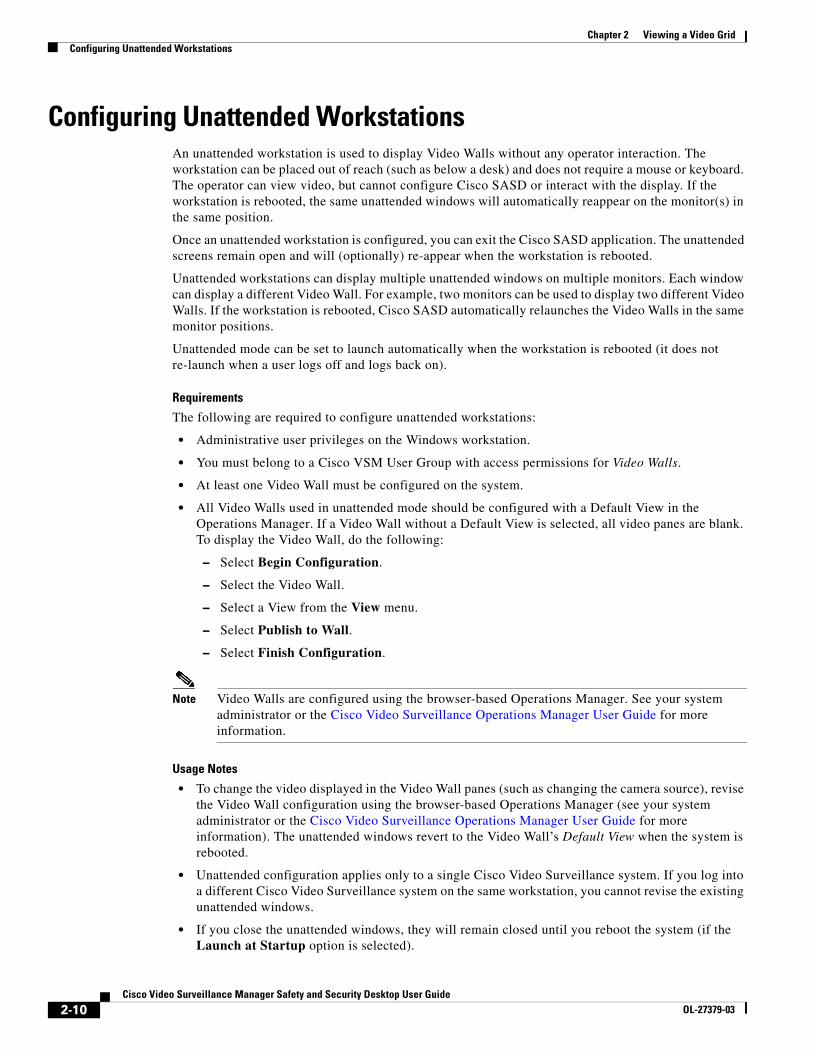
Configuring Unattended Workstations An unattended workstation is used to display Video Walls without any operator interaction. The workstation can be placed out of reach (such as below a desk) and does not require a mouse or keyboard. The operator can view video, but cannot configure Cisco SASD or interact with the display. If the workstation is rebooted, the same unattended windows will automatically reappear on the monitor(s) in the same position.
Once an unattended workstation is configured, you can exit the Cisco SASD application. The unattended screens remain open and will (optionally) re-appear when the workstation is rebooted.
Unattended workstations can display multiple unattended windows on multiple monitors. Each window can display a different Video Wall. For example, two monitors can be used to display two different Video Walls. If the workstation is rebooted, Cisco SASD automatically relaunches the Video Walls in the same monitor positions.
Unattended mode can be set to launch automatically when the workstation is rebooted (it does not re-launch when a user logs off and logs back on).
Requirements
The following are required to configure unattended workstations:
• Administrative user privileges on the Windows workstation.
• You must belong to a Cisco VSM User Group with access permissions for Video Walls.
• At least one Video Wall must be configured on the system.
• All Video Walls used in unattended mode should be configured with a Default View in the Operations Manager. If a Video Wall without a Default View is selected, all video panes are blank. To display the Video Wall, do the following:
– Select Begin Configuration.
– Select the Video Wall.
– Select a View from the View menu.
– Select Publish to Wall.
– Select Finish Configuration.
Note Video Walls are configured using the browser-based Operations Manager. See your system administrator or the Cisco Video Surveillance Operations Manager User Guide for more information.
Usage Notes
• To change the video displayed in the Video Wall panes (such as changing the camera source), revise the Video Wall configuration using the browser-based Operations Manager (see your system administrator or the Cisco Video Surveillance Operations Manager User Guide for more information). The unattended windows revert to the Video Wall’s Default View when the system is rebooted.
• Unattended configuration applies only to a single Cisco Video Surveillance system. If you log into a different Cisco Video Surveillance system on the same workstation, you cannot revise the existing unattended windows.
• If you close the unattended windows, they will remain closed until you reboot the system (if the Launch at Startup option is selected).
2-10Cisco Video Surveillance Manager Safety and Security Desktop User Guide
OL-27379-03
Chapter 2 Viewing a Video GridConfiguring Unattended Workstations
• The unattended mode will repeatedly restart if video to all panes is lost. This can be caused by network or system issues , or if a Video Wall without a default view is selected. This allows unattended mode to recover when the problem is resolved. For example, if the video streams for all panes are provided by a single Media Server, and that Media Server goes down, then the unattended mode will restart until communication with the server is reestablished. If the Media Server fails over to another server, then the new server will provide video streaming and the video will be displayed.
• If the video stream is lost for one (but not all) of the video panes, unattended mode will not restart and the pane will display an error message and icon. The video will automatically re-appear only if the video is in unattended mode and the camera is enabled for failover.
Launch At Startup
The Launch At Startup option allows you to define if the unattended windows will automatically re-launch when the workstation is restarted. Review the following usage notes to understand when the windows will launch
• To change the Launch at Startup option, select File > Unattended SASD Configuration > Begin Configuration to enter configuration mode, as described in the following Procedure.
• Unattended windows will not re-launch when a user logs off and logs back on. The windows re-launch only when the workstation is rebooted.
Procedure
Step 1 Connect a keyboard and mouse to the workstation.
Step 2 Launch Cisco SASD and log in to the application.
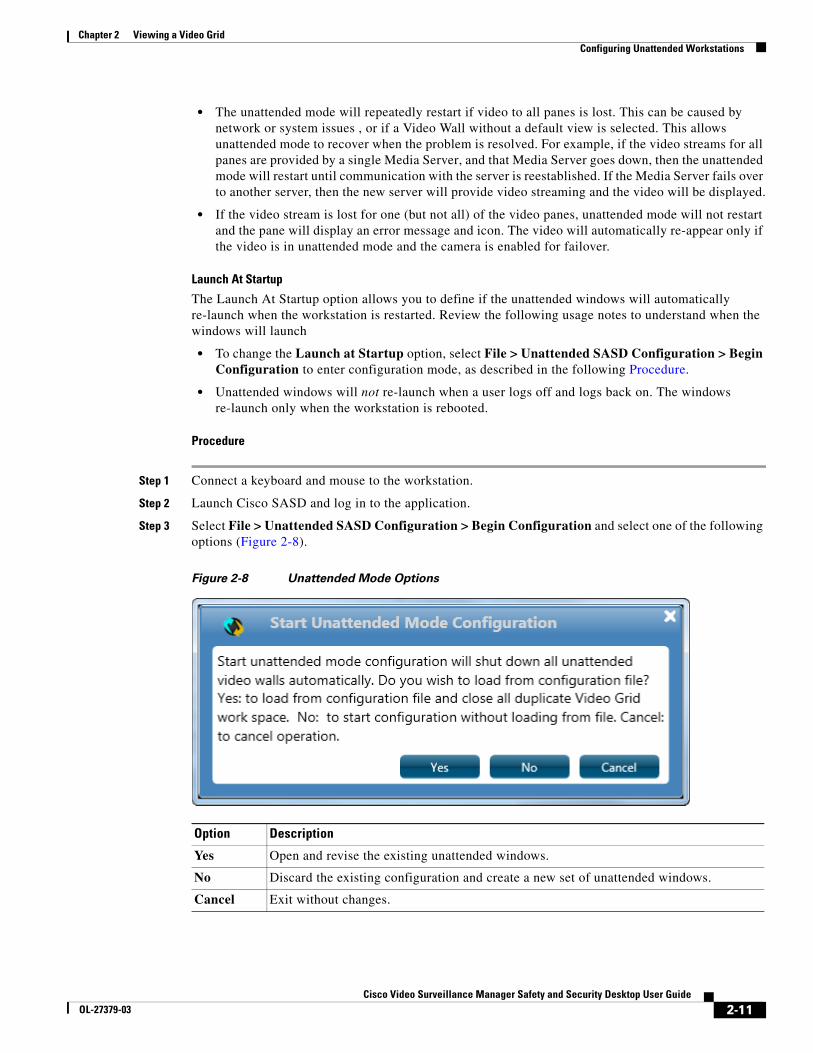
Step 3 Select File > Unattended SASD Configuration > Begin Configuration and select one of the following options (Figure 2-8).
Figure 2-8 Unattended Mode Options
Option Description
Yes Open and revise the existing unattended windows.
No Discard the existing configuration and create a new set of unattended windows.
Cancel Exit without changes.
2-11Cisco Video Surveillance Manager Safety and Security Desktop User Guide
OL-27379-03
Chapter 2 Viewing a Video GridConfiguring Unattended Workstations
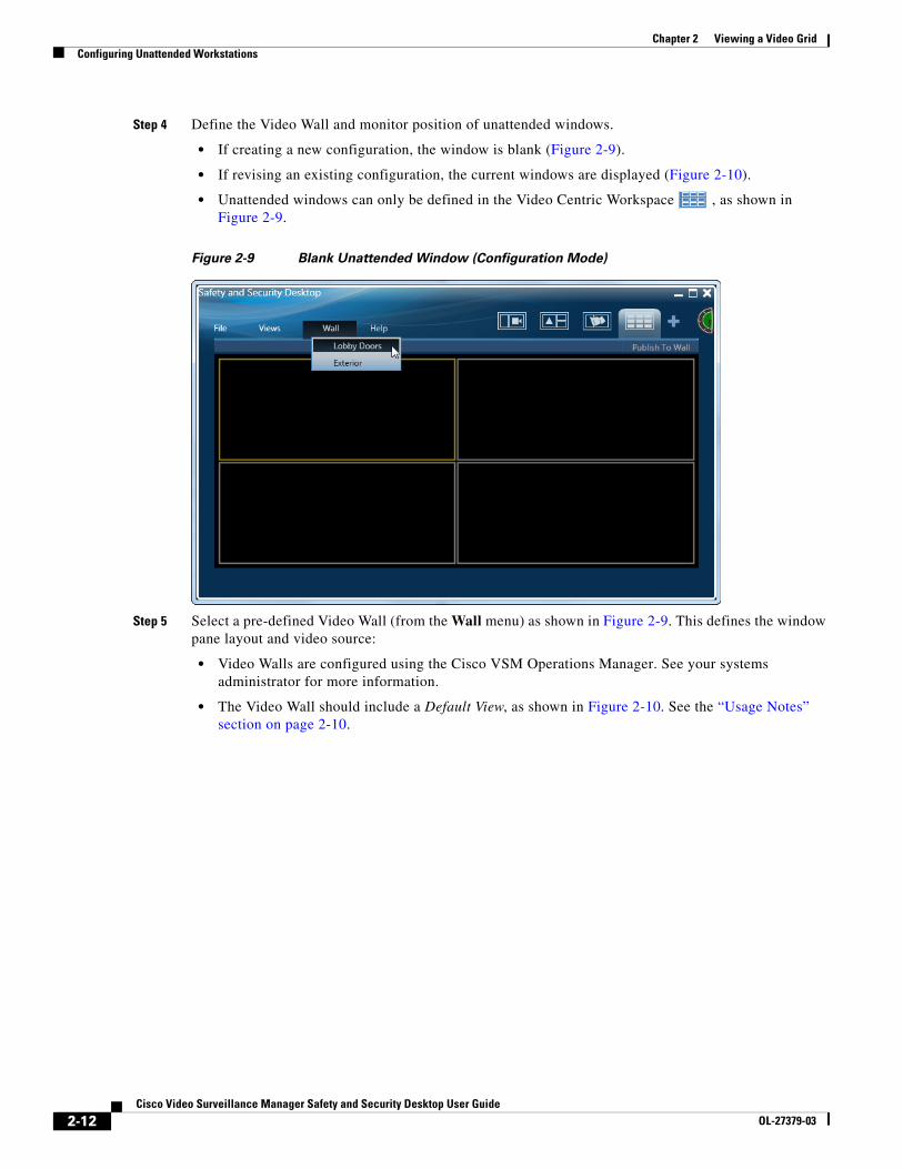
Step 4 Define the Video Wall and monitor position of unattended windows.
• If creating a new configuration, the window is blank (Figure 2-9).
• If revising an existing configuration, the current windows are displayed (Figure 2-10).
• Unattended windows can only be defined in the Video Centric Workspace , as shown in Figure 2-9.
Figure 2-9 Blank Unattended Window (Configuration Mode)
Step 5 Select a pre-defined Video Wall (from the Wall menu) as shown in Figure 2-9. This defines the window pane layout and video source:
• Video Walls are configured using the Cisco VSM Operations Manager. See your systems administrator for more information.
• The Video Wall should include a Default View, as shown in Figure 2-10. See the “Usage Notes” section on page 2-10.
2-12Cisco Video Surveillance Manager Safety and Security Desktop User Guide
OL-27379-03
Chapter 2 Viewing a Video GridConfiguring Unattended Workstations
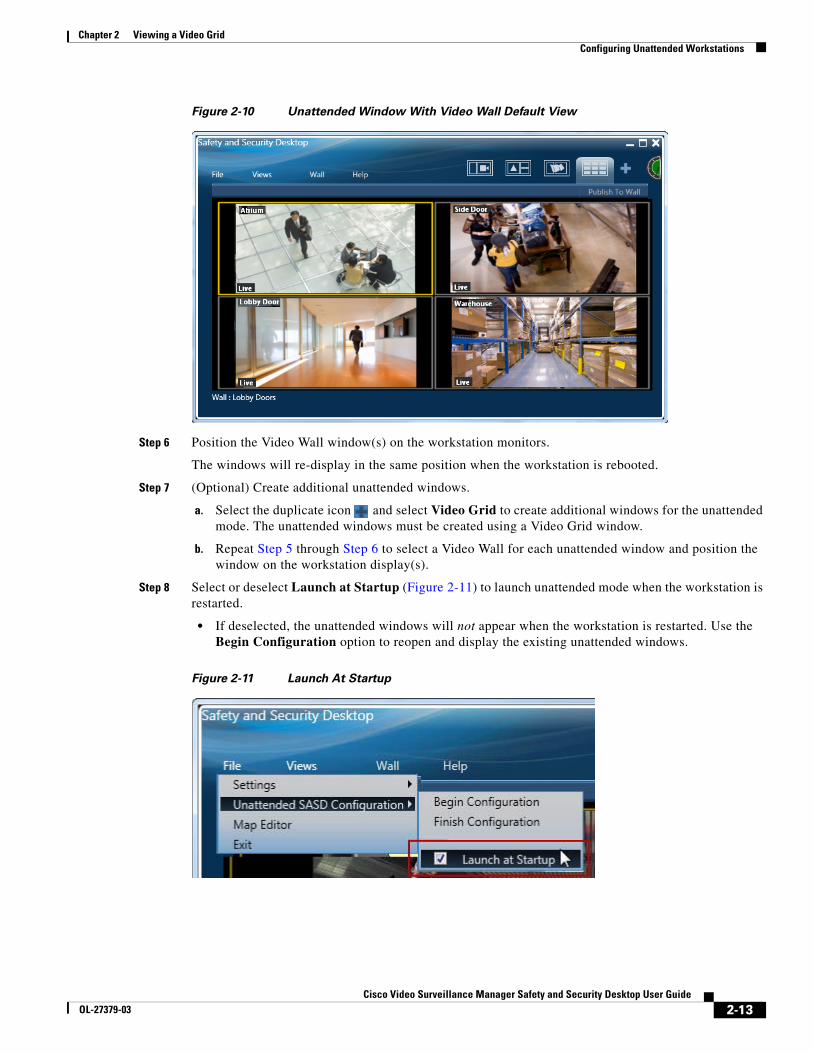
Figure 2-10 Unattended Window With Video Wall Default View
Step 6 Position the Video Wall window(s) on the workstation monitors.
The windows will re-display in the same position when the workstation is rebooted.
Step 7 (Optional) Create additional unattended windows.
a. Select the duplicate icon and select Video Grid to create additional windows for the unattended mode. The unattended windows must be created using a Video Grid window.
b. Repeat Step 5 through Step 6 to select a Video Wall for each unattended window and position the window on the workstation display(s).
Step 8 Select or deselect Launch at Startup (Figure 2-11) to launch unattended mode when the workstation is restarted.
• If deselected, the unattended windows will not appear when the workstation is restarted. Use the Begin Configuration option to reopen and display the existing unattended windows.
Figure 2-11 Launch At Startup
2-13Cisco Video Surveillance Manager Safety and Security Desktop User Guide
OL-27379-03
Chapter 2 Viewing a Video GridConfiguring Unattended Workstations
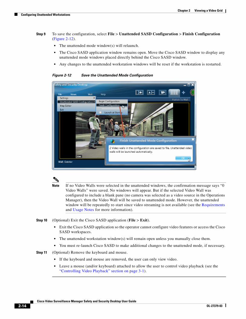
Step 9 To save the configuration, select File > Unattended SASD Configuration > Finish Configuration (Figure 2-12).
• The unattended mode window(s) will relaunch.
• The Cisco SASD application window remains open. Move the Cisco SASD window to display any unattended mode windows placed directly behind the Cisco SASD window.
• Any changes to the unattended workstation windows will be reset if the workstation is restarted.
Figure 2-12 Save the Unattended Mode Configuration
Note If no Video Walls were selected in the unattended windows, the confirmation message says “0 Video Walls” were saved. No windows will appear. But if the selected Video Wall was configured to include a blank pane (no camera was selected as a video source in the Operations Manager), then the Video Wall will be saved to unattended mode. However, the unattended window will be repeatedly re-start since video streaming is not available (see the Requirements and Usage Notes for more information).
Step 10 (Optional) Exit the Cisco SASD application (File > Exit).
• Exit the Cisco SASD application so the operator cannot configure video features or access the Cisco SASD workspaces.
• The unattended workstation window(s) will remain open unless you manually close them.
• You must re-launch Cisco SASD to make additional changes to the unattended mode, if necessary.
Step 11 (Optional) Remove the keyboard and mouse.
• If the keyboard and mouse are removed, the user can only view video.
• Leave a mouse (and/or keyboard) attached to allow the user to control video playback (see the “Controlling Video Playback” section on page 3-1).
2-14Cisco Video Surveillance Manager Safety and Security Desktop User Guide
OL-27379-03
Cisco Video SurveillancOL-27379-03
C H A P T E R 3
Controlling Video PlaybackEach video viewing pane in a Cisco Video Surveillance monitoring application supports the following controls and features.
The features available on your workstation depend on the following:
• The camera and system configuration.
• Your user account access permissions.
• The features supported by the video monitoring application.
Contents
Refer to the following topics for more information.
• Overview, page 3-2
• Viewing Live Video, page 3-3
• Viewing Recorded Video, page 3-6
• Creating Video Clips, page 3-10
• Using Record Now, page 3-17
• Using the Pop-Up Menu, page 3-18
• Understanding Video Pane Border Colors, page 3-19
• Using the Smooth Video Options When Viewing Live Video, page 3-20
• Synchronizing Video Playback in Multiple Panes, page 3-21
• Using Pan, Tilt, and Zoom (PTZ) Controls, page 3-24
3-1e Manager Safety and Security Desktop User Guide
Chapter 3 Controlling Video Playback
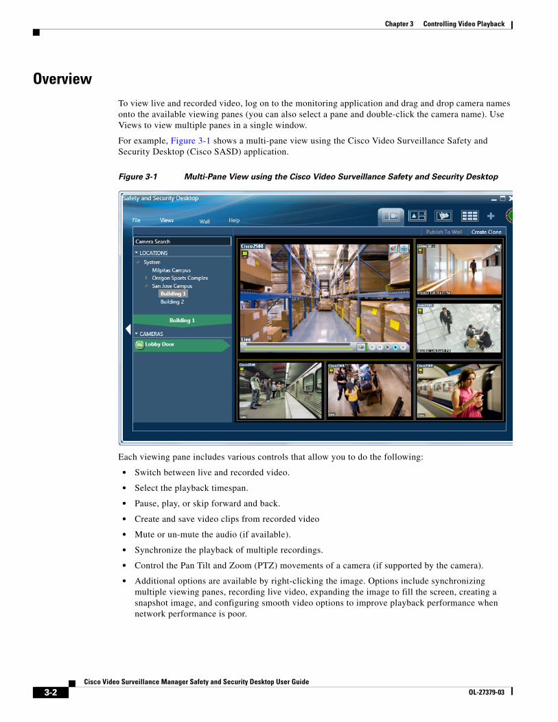
OverviewTo view live and recorded video, log on to the monitoring application and drag and drop camera names onto the available viewing panes (you can also select a pane and double-click the camera name). Use Views to view multiple panes in a single window.
For example, Figure 3-1 shows a multi-pane view using the Cisco Video Surveillance Safety and Security Desktop (Cisco SASD) application.
Figure 3-1 Multi-Pane View using the Cisco Video Surveillance Safety and Security Desktop
Each viewing pane includes various controls that allow you to do the following:
• Switch between live and recorded video.
• Select the playback timespan.
• Pause, play, or skip forward and back.
• Create and save video clips from recorded video
• Mute or un-mute the audio (if available).
• Synchronize the playback of multiple recordings.
• Control the Pan Tilt and Zoom (PTZ) movements of a camera (if supported by the camera).
• Additional options are available by right-clicking the image. Options include synchronizing multiple viewing panes, recording live video, expanding the image to fill the screen, creating a snapshot image, and configuring smooth video options to improve playback performance when network performance is poor.
3-2Cisco Video Surveillance Manager Safety and Security Desktop User Guide
OL-27379-03
Chapter 3 Controlling Video Playback
Note The available controls depend on the camera model and system configuration. For example, pan-tilt-zoom (PTZ) controls are available only on cameras that support PTZ. Recording options are available only if the camera is configured to record video. Synchronized playback is available for recorded video (not live video). See your system administrator for more information.
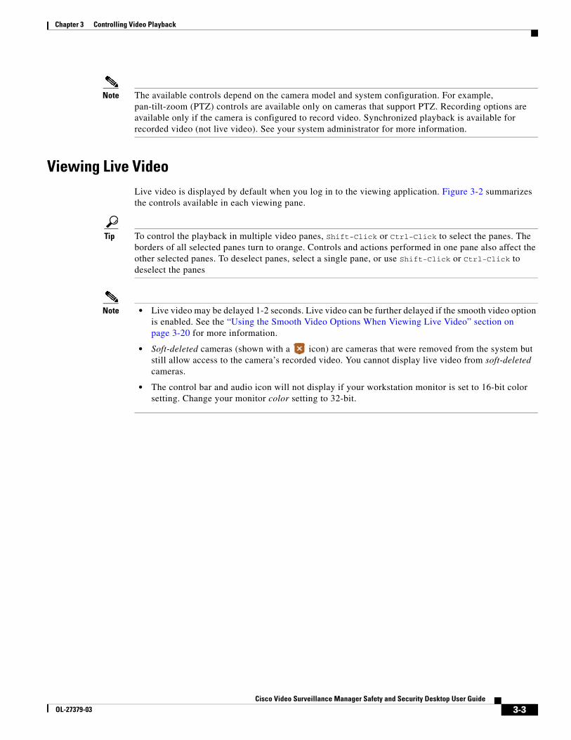
Viewing Live VideoLive video is displayed by default when you log in to the viewing application. Figure 3-2 summarizes the controls available in each viewing pane.
Tip To control the playback in multiple video panes, Shift-Click or Ctrl-Click to select the panes. The borders of all selected panes turn to orange. Controls and actions performed in one pane also affect the other selected panes. To deselect panes, select a single pane, or use Shift-Click or Ctrl-Click to deselect the panes
Note • Live video may be delayed 1-2 seconds. Live video can be further delayed if the smooth video option is enabled. See the “Using the Smooth Video Options When Viewing Live Video” section on page 3-20 for more information.
• Soft-deleted cameras (shown with a icon) are cameras that were removed from the system but still allow access to the camera’s recorded video. You cannot display live video from soft-deleted cameras.
• The control bar and audio icon will not display if your workstation monitor is set to 16-bit color setting. Change your monitor color setting to 32-bit.
3-3Cisco Video Surveillance Manager Safety and Security Desktop User Guide
OL-27379-03
Chapter 3 Controlling Video Playback
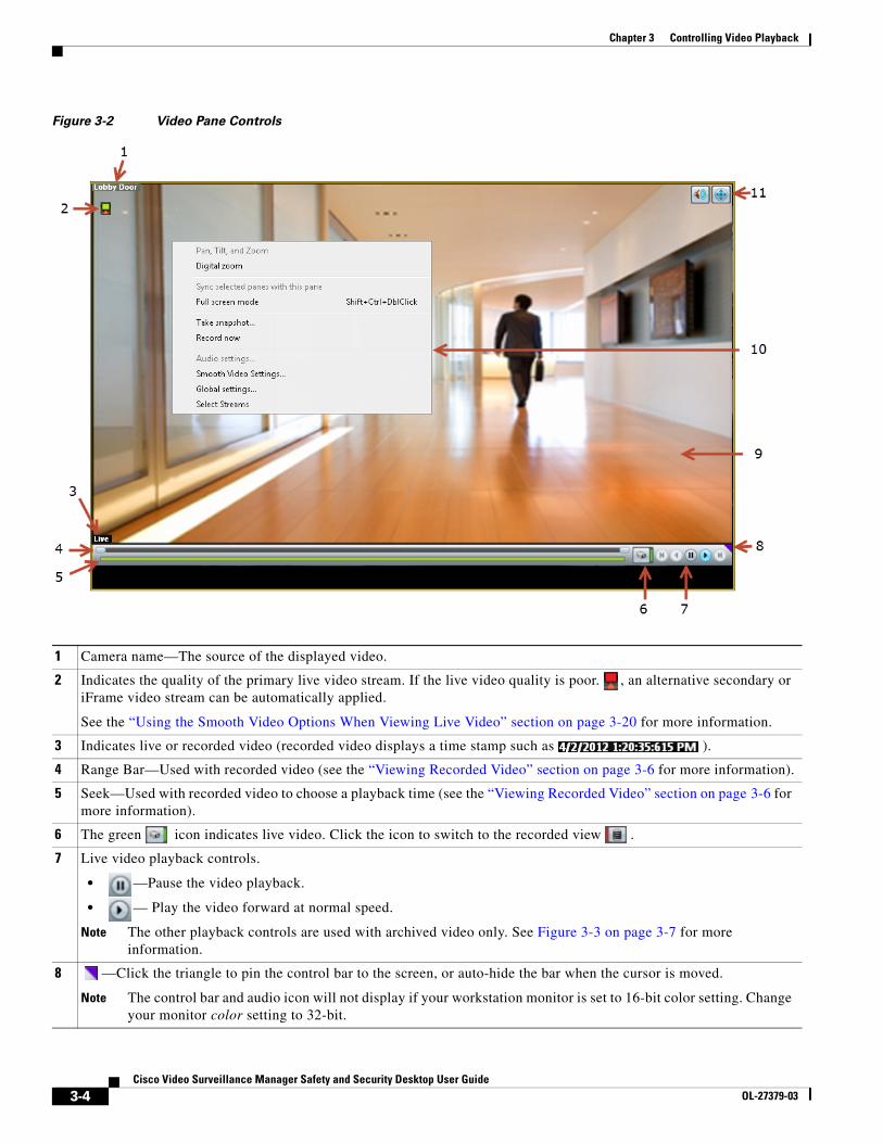
Figure 3-2 Video Pane Controls
1 Camera name—The source of the displayed video.
2 Indicates the quality of the primary live video stream. If the live video quality is poor. , an alternative secondary or iFrame video stream can be automatically applied.
See the “Using the Smooth Video Options When Viewing Live Video” section on page 3-20 for more information.
3 Indicates live or recorded video (recorded video displays a time stamp such as ).
4 Range Bar—Used with recorded video (see the “Viewing Recorded Video” section on page 3-6 for more information).
5 Seek—Used with recorded video to choose a playback time (see the “Viewing Recorded Video” section on page 3-6 for more information).
6 The green icon indicates live video. Click the icon to switch to the recorded view .
7 Live video playback controls.
• —Pause the video playback.
• — Play the video forward at normal speed.
Note The other playback controls are used with archived video only. See Figure 3-3 on page 3-7 for more information.
8 —Click the triangle to pin the control bar to the screen, or auto-hide the bar when the cursor is moved.
Note The control bar and audio icon will not display if your workstation monitor is set to 16-bit color setting. Change your monitor color setting to 32-bit.
3-4Cisco Video Surveillance Manager Safety and Security Desktop User Guide
OL-27379-03
Chapter 3 Controlling Video Playback
Additional Information
Refer to the following topics for additional options:
• Using Record Now, page 3-17
• Using the Pop-Up Menu, page 3-18
• Using the Smooth Video Options When Viewing Live Video, page 3-20
• Synchronizing Video Playback in Multiple Panes, page 3-21
• Using Pan, Tilt, and Zoom (PTZ) Controls, page 3-24
9 Video image.
10 Camera menu.
Right-click the image to open the menu and select an option. Options not supported by the camera are disabled (shown in gray). See the “Using the Pop-Up Menu” section on page 3-18 for more information.
11 Control icons.
• —Audio. The audio icon appears if the camera supports audio. Click the icon to enable or mute live audio volume. This control does not affect recorded video.
• —PTZ. Click to enable or disable the Pan, Tilt and Zoom (PTZ) controls. See the “Using Pan, Tilt, and Zoom (PTZ) Controls” section on page 3-24.
• — See the “Synchronizing Video Playback in Multiple Panes” section on page 3-21.
Note The control bar and audio icon will not display if your workstation monitor is set to 16-bit color setting. Change your monitor color setting to 32-bit.
3-5Cisco Video Surveillance Manager Safety and Security Desktop User Guide
OL-27379-03
Chapter 3 Controlling Video Playback
Viewing Recorded VideoYou can view recorded video from a continuos loop, for a motion event, or from a video clip. The camera must be configured to support each of these options, and you must have access to a video viewing application that supports these functions (some applications are used for viewing only).
For example, a camera can be configured to record the following:
• Continuous recordings that include video from a set amount of time, such as the past 60 minutes.
• Motion event recordings that are triggered whenever a motion event occurs. Video is recorded when the motion occurs, and for a configured number of seconds before and after the event. Use a video viewing application (such as the Cisco Video Surveillance Safety and Security Desktop) to view motion event video.
Tip To control the playback in multiple video panes, press Shift-Click to select multiple concurrent panes, or Ctrl-Click to select individual panes. The borders of all selected panes turn to orange. Controls and actions performed in one pane also affect the other selected panes. To deselect panes, select a single pane, or use Shift-Click or Ctrl-Click to deselect the panes
Usage Notes
• Multi-pane video clips can also be saved to your desktop and played using the Cisco Video Surveillance Review Player.
• If the Record Now feature is enabled, right-click the image and choose Record Now to record live video.
• If a camera is soft-deleted, you can still access the camera’s recorded video but cannot display live video. Recordings are retained on the system until removed according to the recording retention settings.
• Click the icon to toggle between live and recorded video. The icon appears when recorded video is displayed.
• The first time you select a camera’s recorded video, the playback begins slightly behind the live (current) time. When you toggle between live and recorded, recorded video returns to the previously selected timestamp.
3-6Cisco Video Surveillance Manager Safety and Security Desktop User Guide
OL-27379-03
Chapter 3 Controlling Video Playback
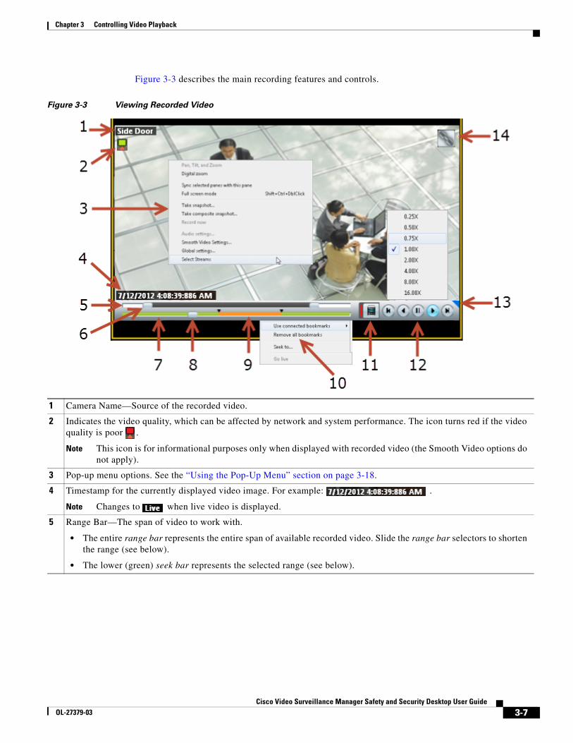
Figure 3-3 describes the main recording features and controls.
Figure 3-3 Viewing Recorded Video
1 Camera Name—Source of the recorded video.
2 Indicates the video quality, which can be affected by network and system performance. The icon turns red if the video quality is poor .
Note This icon is for informational purposes only when displayed with recorded video (the Smooth Video options do not apply).
3 Pop-up menu options. See the “Using the Pop-Up Menu” section on page 3-18.
4 Timestamp for the currently displayed video image. For example: .
Note Changes to when live video is displayed.
5 Range Bar—The span of video to work with.
• The entire range bar represents the entire span of available recorded video. Slide the range bar selectors to shorten the range (see below).
• The lower (green) seek bar represents the selected range (see below).
3-7Cisco Video Surveillance Manager Safety and Security Desktop User Guide
OL-27379-03
Chapter 3 Controlling Video Playback
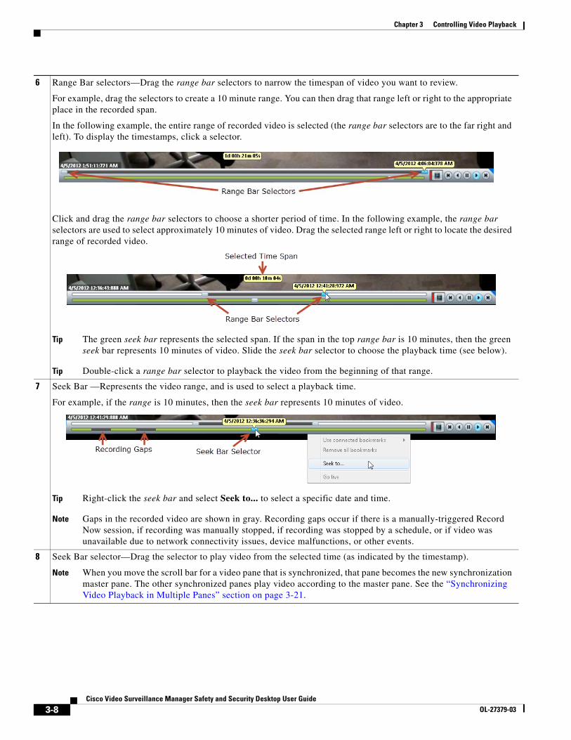
6 Range Bar selectors—Drag the range bar selectors to narrow the timespan of video you want to review.
For example, drag the selectors to create a 10 minute range. You can then drag that range left or right to the appropriate place in the recorded span.
In the following example, the entire range of recorded video is selected (the range bar selectors are to the far right and left). To display the timestamps, click a selector.
Click and drag the range bar selectors to choose a shorter period of time. In the following example, the range bar selectors are used to select approximately 10 minutes of video. Drag the selected range left or right to locate the desired range of recorded video.
Tip The green seek bar represents the selected span. If the span in the top range bar is 10 minutes, then the green seek bar represents 10 minutes of video. Slide the seek bar selector to choose the playback time (see below).
Tip Double-click a range bar selector to playback the video from the beginning of that range.
7 Seek Bar —Represents the video range, and is used to select a playback time.
For example, if the range is 10 minutes, then the seek bar represents 10 minutes of video.
Tip Right-click the seek bar and select Seek to... to select a specific date and time.
Note Gaps in the recorded video are shown in gray. Recording gaps occur if there is a manually-triggered Record Now session, if recording was manually stopped, if recording was stopped by a schedule, or if video was unavailable due to network connectivity issues, device malfunctions, or other events.
8 Seek Bar selector—Drag the selector to play video from the selected time (as indicated by the timestamp).
Note When you move the scroll bar for a video pane that is synchronized, that pane becomes the new synchronization master pane. The other synchronized panes play video according to the master pane. See the “Synchronizing Video Playback in Multiple Panes” section on page 3-21.
3-8Cisco Video Surveillance Manager Safety and Security Desktop User Guide
OL-27379-03
Chapter 3 Controlling Video Playback
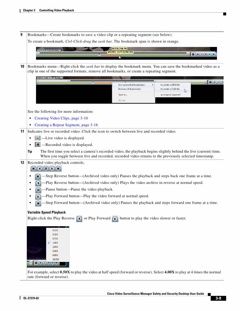
9 Bookmarks—Create bookmarks to save a video clip or a repeating segment (see below).
To create a bookmark, Ctrl-Click-drag the seek bar. The bookmark span is shown in orange.
10 Bookmarks menu—Right-click the seek bar to display the bookmark menu. You can save the bookmarked video as a clip in one of the supported formats, remove all bookmarks, or create a repeating segment.
See the following for more information:
• Creating Video Clips, page 3-10
• Creating a Repeat Segment, page 3-16
11 Indicates live or recorded video. Click the icon to switch between live and recorded video.
• —Live video is displayed.
• —Recorded video is displayed.
Tip The first time you select a camera’s recorded video, the playback begins slightly behind the live (current) time. When you toggle between live and recorded, recorded video returns to the previously selected timestamp.
12 Recorded video playback controls.
• —Step Reverse button—(Archived video only) Pauses the playback and steps back one frame at a time.
• —Play Reverse button—(Archived video only) Plays the video archive in reverse at normal speed.
• —Pause button—Pause the video playback.
• —Play Forward button—Play the video forward at normal speed.
• —Step Forward button—(Archived video only) Pauses the playback and steps forward one frame at a time.
Variable Speed Playback
Right-click the Play Reverse or Play Forward button to play the video slower or faster.
For example, select 0.50X to play the video at half speed (forward or reverse). Select 4.00X to play at 4 times the normal rate (forward or reverse).
3-9Cisco Video Surveillance Manager Safety and Security Desktop User Guide
OL-27379-03
Chapter 3 Controlling Video Playback
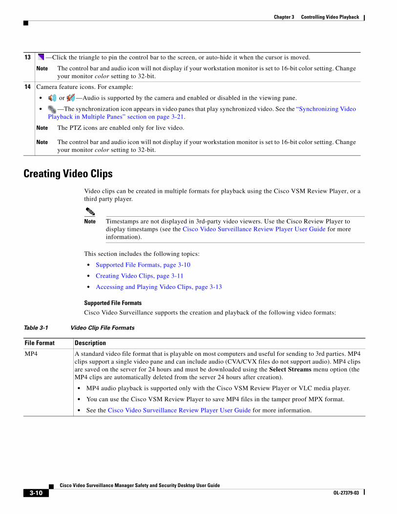
Creating Video ClipsVideo clips can be created in multiple formats for playback using the Cisco VSM Review Player, or a third party player.
Note Timestamps are not displayed in 3rd-party video viewers. Use the Cisco Review Player to display timestamps (see the Cisco Video Surveillance Review Player User Guide for more information).
This section includes the following topics:
• Supported File Formats, page 3-10
• Creating Video Clips, page 3-11
• Accessing and Playing Video Clips, page 3-13
Supported File Formats
Cisco Video Surveillance supports the creation and playback of the following video formats:
13 —Click the triangle to pin the control bar to the screen, or auto-hide it when the cursor is moved.
Note The control bar and audio icon will not display if your workstation monitor is set to 16-bit color setting. Change your monitor color setting to 32-bit.
14 Camera feature icons. For example:
• or —Audio is supported by the camera and enabled or disabled in the viewing pane.
• —The synchronization icon appears in video panes that play synchronized video. See the “Synchronizing Video Playback in Multiple Panes” section on page 3-21.
Note The PTZ icons are enabled only for live video.
Note The control bar and audio icon will not display if your workstation monitor is set to 16-bit color setting. Change your monitor color setting to 32-bit.
Table 3-1 Video Clip File Formats
File Format Description
MP4 A standard video file format that is playable on most computers and useful for sending to 3rd parties. MP4 clips support a single video pane and can include audio (CVA/CVX files do not support audio). MP4 clips are saved on the server for 24 hours and must be downloaded using the Select Streams menu option (the MP4 clips are automatically deleted from the server 24 hours after creation).
• MP4 audio playback is supported only with the Cisco VSM Review Player or VLC media player.
• You can use the Cisco VSM Review Player to save MP4 files in the tamper proof MPX format.
• See the Cisco Video Surveillance Review Player User Guide for more information.
3-10Cisco Video Surveillance Manager Safety and Security Desktop User Guide
OL-27379-03
Chapter 3 Controlling Video Playback
Tip You can also right-click a video pane and select Take Snapshot to save a still image in BMP, JPEG, PNG, and TIFF formats. See the “Using the Pop-Up Menu” section on page 3-18 for more information.
Creating Video Clips
To create video clips, create a bookmark span and select the file format, as described in the following procedure.
Notes:
• The Media Server hard disk volume must have sufficient disk space to create the video clip or the operation will fail. See your system administrator for more information.
• MP4 clips:
– MP4 files are stored on the server until you download them. Clips are automatically deleted after 24 hours, or when downloaded to a local disk.
– MP4 clips can only be downloaded by the user who created the clip.
– You can only create up to five MP4 clips at a time per Media Server.
– MP4 clipping failure can only be viewed in the Cisco Video Surveillance Safety and Security Desktop (Cisco SASD) Alert workspace.
• CVA/CVX clips are downloaded immediately and not stored on the server.
• If the clipping fails, see your system administrator for assistance.
Procedure:
Step 1 Select a video pane from the viewing application (such as Cisco SASD or Operations Manager).
Tip To create a multi-pane clip in the CVA format, press Shift-Click to select multiple concurrent panes, or Ctrl-Click to select individual panes.
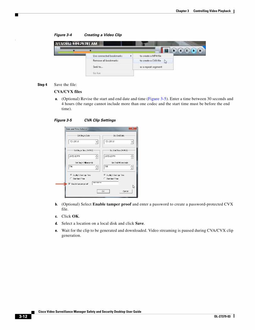
Step 2 In the green seek bar, Ctrl-Click and drag the mouse cursor to create a bookmark span. The bookmark span is shown in orange (Figure 3-4).
Step 3 Right-click the bookmark and select Use connected bookmarks (Figure 3-4) to create a file in the desired format.
CVA Cisco video archives (CVA) can include multiple video panes that synchronize to the same time. CVA files can only be opened in applications that support the CVA format (such as the Cisco Review Player).
CVA files do not support audio playback.
CVX A tamper proof CVA file. CVX files require a password that is entered when the file is created. You must enter the password to open and view the video file. CVX video playback will shut down if the file is tampered with.
CVX files do not support audio.
Table 3-1 Video Clip File Formats (continued)
File Format Description
3-11Cisco Video Surveillance Manager Safety and Security Desktop User Guide
OL-27379-03
Chapter 3 Controlling Video Playback
Figure 3-4 Creating a Video Clip.
Step 4 Save the file:
CVA/CVX files
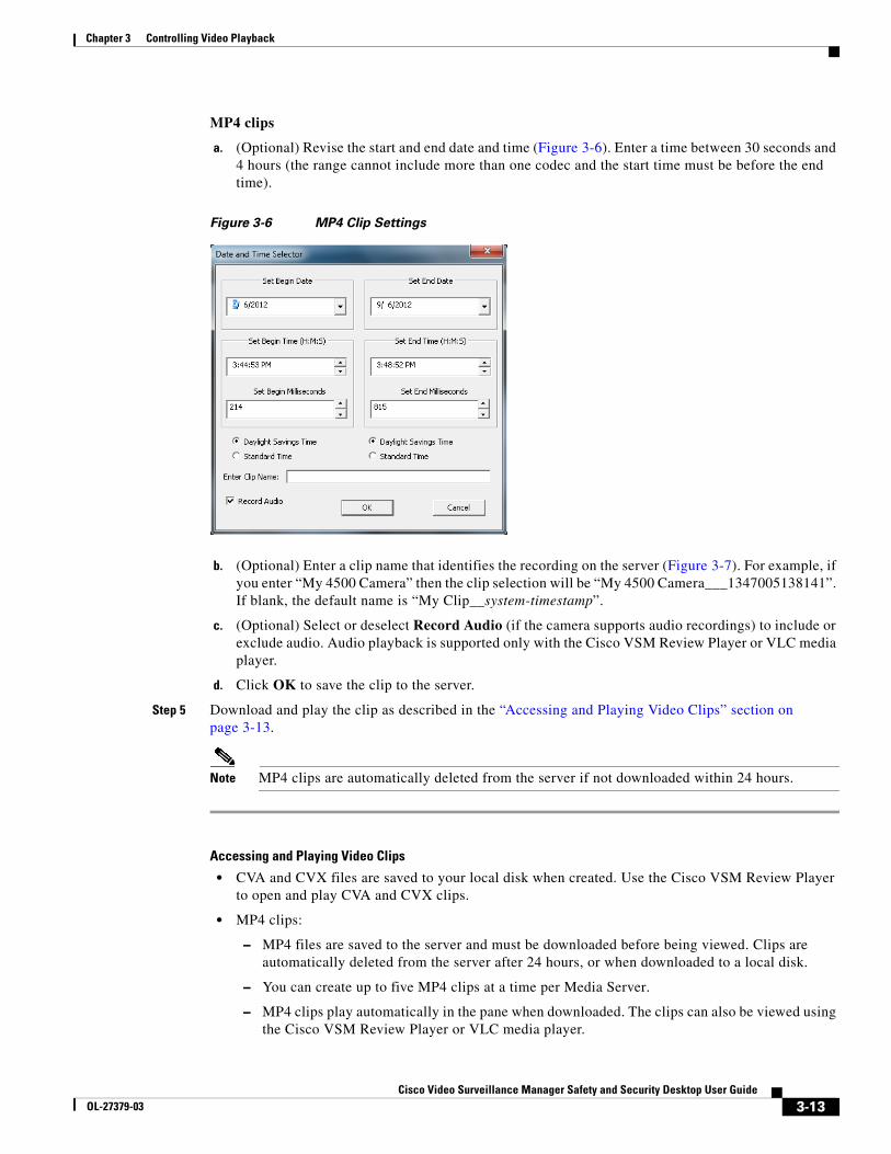
a. (Optional) Revise the start and end date and time (Figure 3-5). Enter a time between 30 seconds and 4 hours (the range cannot include more than one codec and the start time must be before the end time).
Figure 3-5 CVA Clip Settings
b. (Optional) Select Enable tamper proof and enter a password to create a password-protected CVX file.
c. Click OK.
d. Select a location on a local disk and click Save.
e. Wait for the clip to be generated and downloaded. Video streaming is paused during CVA/CVX clip generation.
3-12Cisco Video Surveillance Manager Safety and Security Desktop User Guide
OL-27379-03
Chapter 3 Controlling Video Playback
MP4 clips
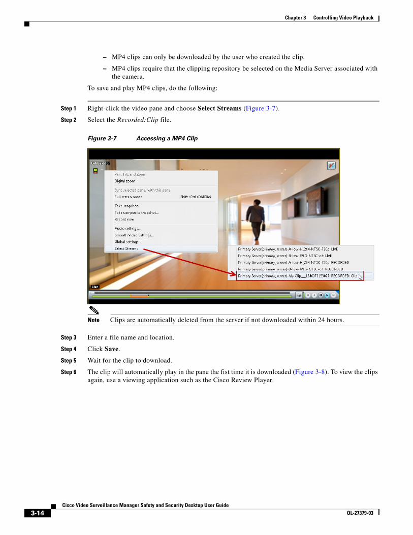
a. (Optional) Revise the start and end date and time (Figure 3-6). Enter a time between 30 seconds and 4 hours (the range cannot include more than one codec and the start time must be before the end time).
Figure 3-6 MP4 Clip Settings
b. (Optional) Enter a clip name that identifies the recording on the server (Figure 3-7). For example, if you enter “My 4500 Camera” then the clip selection will be “My 4500 Camera___1347005138141”. If blank, the default name is “My Clip__system-timestamp”.
c. (Optional) Select or deselect Record Audio (if the camera supports audio recordings) to include or exclude audio. Audio playback is supported only with the Cisco VSM Review Player or VLC media player.
d. Click OK to save the clip to the server.
Step 5 Download and play the clip as described in the “Accessing and Playing Video Clips” section on page 3-13.
Note MP4 clips are automatically deleted from the server if not downloaded within 24 hours.
Accessing and Playing Video Clips
• CVA and CVX files are saved to your local disk when created. Use the Cisco VSM Review Player to open and play CVA and CVX clips.
• MP4 clips:
– MP4 files are saved to the server and must be downloaded before being viewed. Clips are automatically deleted from the server after 24 hours, or when downloaded to a local disk.
– You can create up to five MP4 clips at a time per Media Server.
– MP4 clips play automatically in the pane when downloaded. The clips can also be viewed using the Cisco VSM Review Player or VLC media player.
3-13Cisco Video Surveillance Manager Safety and Security Desktop User Guide
OL-27379-03
Chapter 3 Controlling Video Playback
– MP4 clips can only be downloaded by the user who created the clip.
– MP4 clips require that the clipping repository be selected on the Media Server associated with the camera.
To save and play MP4 clips, do the following:
Step 1 Right-click the video pane and choose Select Streams (Figure 3-7).
Step 2 Select the Recorded:Clip file.
Figure 3-7 Accessing a MP4 Clip
Note Clips are automatically deleted from the server if not downloaded within 24 hours.
Step 3 Enter a file name and location.
Step 4 Click Save.
Step 5 Wait for the clip to download.
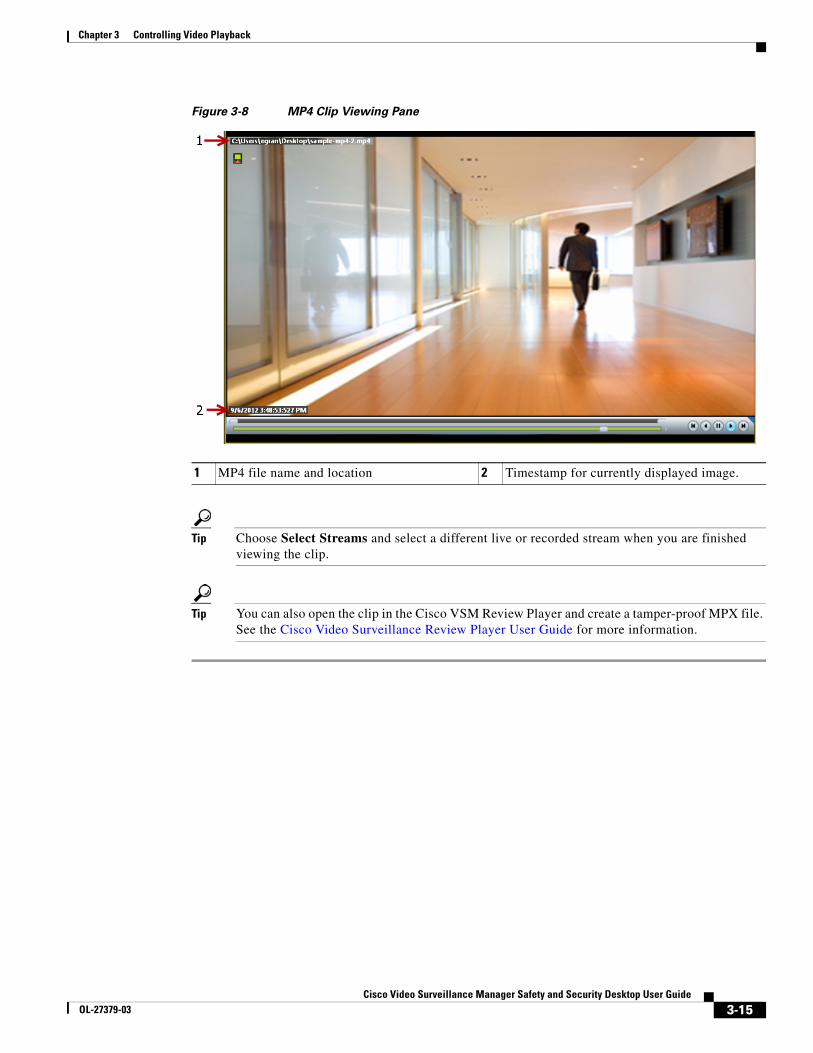
Step 6 The clip will automatically play in the pane the fist time it is downloaded (Figure 3-8). To view the clips again, use a viewing application such as the Cisco Review Player.
3-14Cisco Video Surveillance Manager Safety and Security Desktop User Guide
OL-27379-03
Chapter 3 Controlling Video Playback
Figure 3-8 MP4 Clip Viewing Pane
1 MP4 file name and location 2 Timestamp for currently displayed image.
Tip Choose Select Streams and select a different live or recorded stream when you are finished viewing the clip.
Tip You can also open the clip in the Cisco VSM Review Player and create a tamper-proof MPX file. See the Cisco Video Surveillance Review Player User Guide for more information.
3-15Cisco Video Surveillance Manager Safety and Security Desktop User Guide
OL-27379-03
Chapter 3 Controlling Video Playback
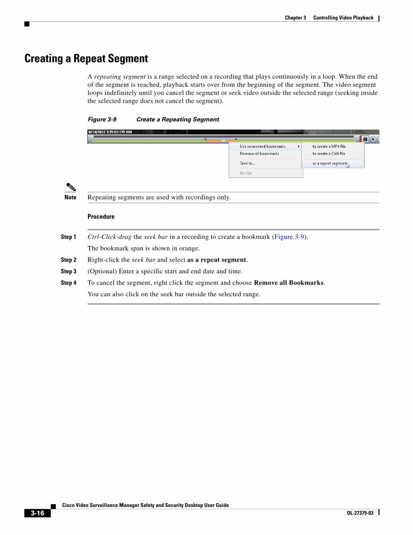
Creating a Repeat SegmentA repeating segment is a range selected on a recording that plays continuously in a loop. When the end of the segment is reached, playback starts over from the beginning of the segment. The video segment loops indefinitely until you cancel the segment or seek video outside the selected range (seeking inside the selected range does not cancel the segment).
Figure 3-9 Create a Repeating Segment
Note Repeating segments are used with recordings only.
Procedure
Step 1 Ctrl-Click-drag the seek bar in a recording to create a bookmark (Figure 3-9).
The bookmark span is shown in orange.
Step 2 Right-click the seek bar and select as a repeat segment.
Step 3 (Optional) Enter a specific start and end date and time.
Step 4 To cancel the segment, right click the segment and choose Remove all Bookmarks.
You can also click on the seek bar outside the selected range.
3-16Cisco Video Surveillance Manager Safety and Security Desktop User Guide
OL-27379-03
Chapter 3 Controlling Video Playback
Using Record NowTo manually trigger recording of a live video stream, right-click the image and choose Record Now.
Requirements
• The Record Now option must be enabled for the camera configuration in the Operations Manager.
• Your use account must include access permissions to view recorded video.
• You can record video from the live primary video stream only.
Usage Notes
• Audio is not recorded.
• Video is recorded for a system-defined length of time (the default is 5 minutes).
• The recording is retained on the system according to the event retention settings for the camera. For example, if the camera’s event recordings are retained for 30 days, then the Record Now recordings will also be available for 30 days. When the retention time is exceeded, the recording is automatically deleted (see the “Creating Video Clips” section on page 3-10 to save the video to a separate file).
Procedure
Step 1 Log in to the video viewing application and select a camera.
Step 2 Choose live video (see the “Viewing Live Video” section on page 3-3).
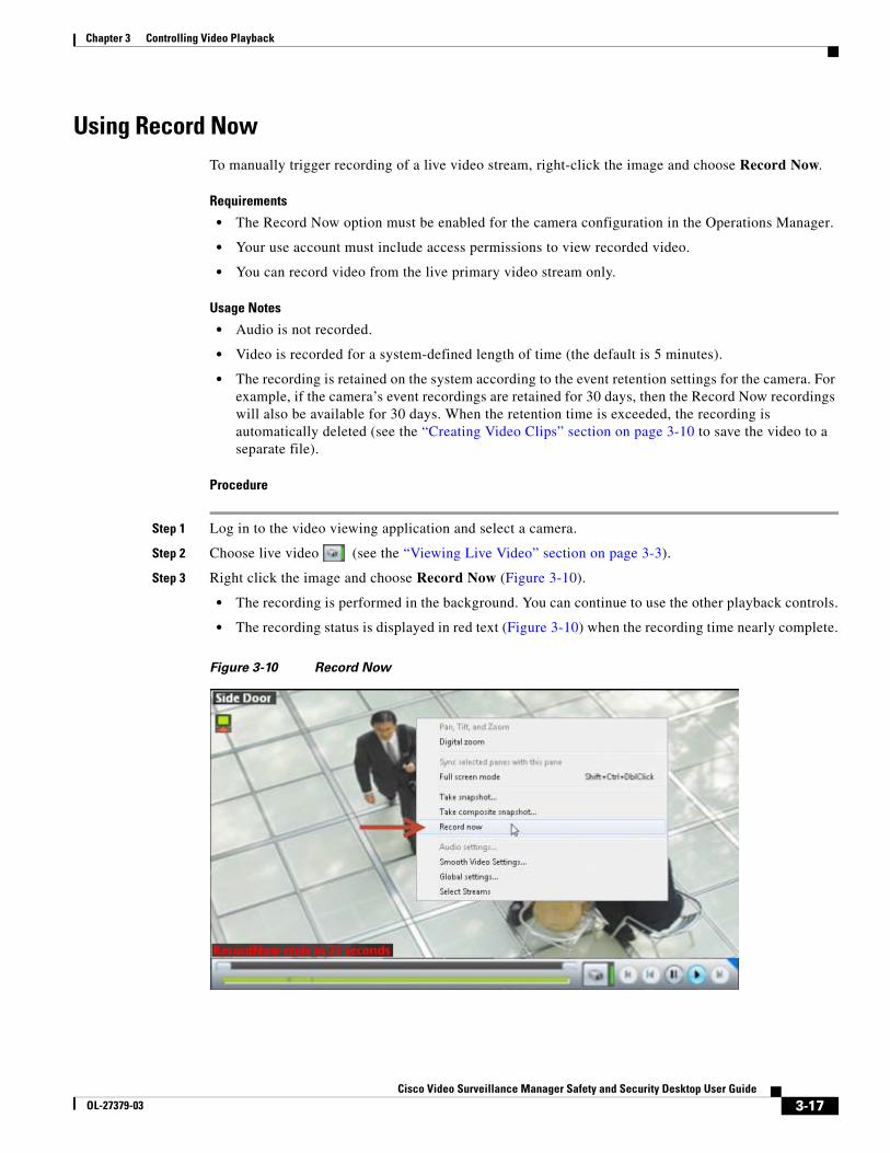
Step 3 Right click the image and choose Record Now (Figure 3-10).
• The recording is performed in the background. You can continue to use the other playback controls.
• The recording status is displayed in red text (Figure 3-10) when the recording time nearly complete.
Figure 3-10 Record Now
3-17Cisco Video Surveillance Manager Safety and Security Desktop User Guide
OL-27379-03
Chapter 3 Controlling Video Playback
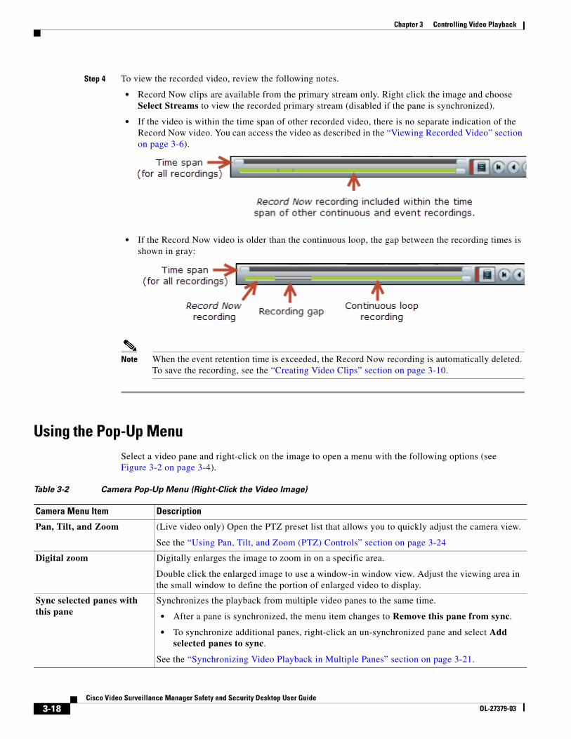
Step 4 To view the recorded video, review the following notes.
• Record Now clips are available from the primary stream only. Right click the image and choose Select Streams to view the recorded primary stream (disabled if the pane is synchronized).
• If the video is within the time span of other recorded video, there is no separate indication of the Record Now video. You can access the video as described in the “Viewing Recorded Video” section on page 3-6).
• If the Record Now video is older than the continuous loop, the gap between the recording times is shown in gray:
Note When the event retention time is exceeded, the Record Now recording is automatically deleted. To save the recording, see the “Creating Video Clips” section on page 3-10.
Using the Pop-Up MenuSelect a video pane and right-click on the image to open a menu with the following options (see Figure 3-2 on page 3-4).
Table 3-2 Camera Pop-Up Menu (Right-Click the Video Image)
Camera Menu Item Description
Pan, Tilt, and Zoom (Live video only) Open the PTZ preset list that allows you to quickly adjust the camera view.
See the “Using Pan, Tilt, and Zoom (PTZ) Controls” section on page 3-24
Digital zoom Digitally enlarges the image to zoom in on a specific area.
Double click the enlarged image to use a window-in window view. Adjust the viewing area in the small window to define the portion of enlarged video to display.
Sync selected panes with this pane
Synchronizes the playback from multiple video panes to the same time.
• After a pane is synchronized, the menu item changes to Remove this pane from sync.
• To synchronize additional panes, right-click an un-synchronized pane and select Add selected panes to sync.
See the “Synchronizing Video Playback in Multiple Panes” section on page 3-21.
3-18Cisco Video Surveillance Manager Safety and Security Desktop User Guide
OL-27379-03
Chapter 3 Controlling Video Playback
Understanding Video Pane Border ColorsThe color that surrounds a video pane indicates the status of the video in that pane. For example, when you click anywhere in a video pane, the pane becomes active and the border changes to orange. The controls and actions performed apply to the active pane.
Table 3-3 describes the meaning of each color.
Table 3-3 Video Pane Border Colors
Color Description
Gray The pane is not highlighted. All panes have a gray border by default.
Orange The pane is selected as the active pane, and the controls and actions apply to that pane. If multiple panes are selected as active panes, the controls and actions performed on one pane apply to all active panes.
Full screen mode Enlarges the video image to fill your display screen.
Tip To exit, press Esc, or right-click and choose Full screen mode again.
Take snapshot Saves a snapshot of a single video pane (excluding control icons, timestamps and other information) in BMP, JPEG, PNG, or TIFF format.
Take composite snapshot Saves a snapshot of all panes in a multi-pane layout (including control icons, timestamps and other information) in BMP, JPEG, PNG, or TIFF format.
Record now (Live video only) Immediately begins recording video.
See the “Using Record Now” section on page 3-17 for more information.
Note The Record Now option must be enabled in the camera configuration.
Audio settings (Cameras with audio support only). Opens a window used to adjust video playback volume and balance.
Smooth video settings (Live video only) Creates a smooth video playback if the playback is choppy or delayed due to network or other performance issues.
See the “Using the Smooth Video Options When Viewing Live Video” section on page 3-20.
Global settings Provides settings that apply to all video panes. For example: UI transparency and zoom video to fit the pane.
Select streams Allows you to select the live and recorded video streams (primary or secondary) supported by the camera.
Note Select Streams is disabled when the pane is synchronized. See the “Synchronizing Video Playback in Multiple Panes” section on page 3-21 for more information.
Table 3-2 Camera Pop-Up Menu (Right-Click the Video Image) (continued)
Camera Menu Item Description
3-19Cisco Video Surveillance Manager Safety and Security Desktop User Guide
OL-27379-03
Chapter 3 Controlling Video Playback
Using the Smooth Video Options When Viewing Live Video If live video playback is choppy due to network or other performance issues, use the Smooth video settings to automatically do the following:
• Create a video data buffer (in seconds) that delays live playback while video data is cached. Live video can then be played back smoothly despite network delays between the camera, Media Server, and workstation.
• Automatically switch to a different stream if the live video quality is poor.
Icon Colors
The video quality icons in each pane indicate the following:
• Green indicates everything is fine.
• Yellow indicates that the client workstation has detected the play back is not smooth.
• Red indicates a severe adverse situation. Action will be taken to correct the situation, such as switching to secondary stream or iFrame streaming.
Usage Notes
• The Smooth Video Options are available only for live video on non-PTZ cameras (the Smooth Video Options are automatically disabled on PTZ cameras).
• The settings are applied to all non-PTZ cameras and are persistent for the current PC workstation. For example, the settings will remain if you log out and back in, or view a different camera and then return to the current camera.
• The settings also apply to the non-PTZ cameras when using the Cisco Safety and Security Desktop (SASD) application and the Cisco Video Surveillance Management Console.
• The Smooth Video options are disabled if you manually select a stream (right-click a video pane and choose Select Streams). The pane will display the selected stream even if the video quality is poor (the video will not automatically switch to the Smooth Video alternative stream). To cancel the manually selected stream and re-enable the Smooth Video settings, reload the view or drag and drop the camera again.
• If a video stream is selected from a redundant media server, the Smooth Video option is disabled (the camera will not use a secondary stream even if the video quality icon is red).
Procedure
Step 1 Right-click a live video image to open the pop-up menu.
Step 2 Select or deselect Enable Smooth Video for Live non-PTZ Camera to enable the smooth video options.
Step 3 (Optional) Enter the Preroll Buffer Size in Seconds to define the number of seconds that live video will be delayed.
Video data is saved in a cache on your PC to avoid pauses caused by network bandwidth and other issues. We recommend a value between 1.5 and 3 seconds.
3-20Cisco Video Surveillance Manager Safety and Security Desktop User Guide
OL-27379-03
Chapter 3 Controlling Video Playback
Caution We strongly recommend that the Preroll Buffer be disabled (enter 0 or leave the field blank) since streaming delays can cause a potential security risk. We recommend that you address the network bandwidth or performance issues causing the delays. Use the Preroll Buffer only when significant stuttering occurs and a network resolution is not available.
Step 4 Use the Smooth Video Options to define an alternative video stream that will be used if video quality is poor despite the smooth video buffer (video quality is indicated by the icon on the live viewing pane).
• Secondary Stream—(Only if configured on the camera) If the live video quality is poor , the secondary video stream is used. Secondary streams typically present a lower-quality image that requires less bandwidth and processing.
• I frame only—If the live video quality is poor , then only the iFrame video is displayed. iFrame video reduces the bandwidth requirement to correct the situation.
• None—If the live video quality is poor , no change is made and the selected stream is displayed even if it results in choppy or paused playback.
Note • These options are not used if the video quality is acceptable or if the icon is yellow (intermediate) . The selected stream is displayed normally.
• A down arrow is displayed when the secondary or iFrame stream is applied.
• If an alternative stream is applied, the settings remain until you close and reopen the video source (camera).
Synchronizing Video Playback in Multiple PanesTo synchronize video playback from multiple panes, select multiple panes, right-click the pane that defines the master time, and choose Sync Selected Panes With This Pane. All panes will play video from the same date and time.
Usage Notes
• All panes will play forward when synchronization begins, even if one or more of the panes was playing in reverse.
• Synchronization for recorded video is performed only if the time in the selected panes overlap. If the time for a video pane does not overlap with the master pane, the pane is excluded from synchronization.
• When you move the scroll bar for a video pane that is synchronized, that pane becomes the new synchronization master pane. The other synchronized panes play video according to the new master pane.
• If the seek controls are used to search video, the other synchronized panes pause until the seek completes, then continue to display video that is synchronized with the new master pane time.
• You can switch the synchronized panes between live and recorded video.
3-21Cisco Video Surveillance Manager Safety and Security Desktop User Guide
OL-27379-03
Chapter 3 Controlling Video Playback
• To remove a pane from the synchronized playback, right-click the pane and choose Remove This Pane From Sync to remove it.
• To add un-synchronized panes, right-click the pane and choose Add selected panes to sync.
• The Select Streams menu item is disabled when a pane is synchronized.
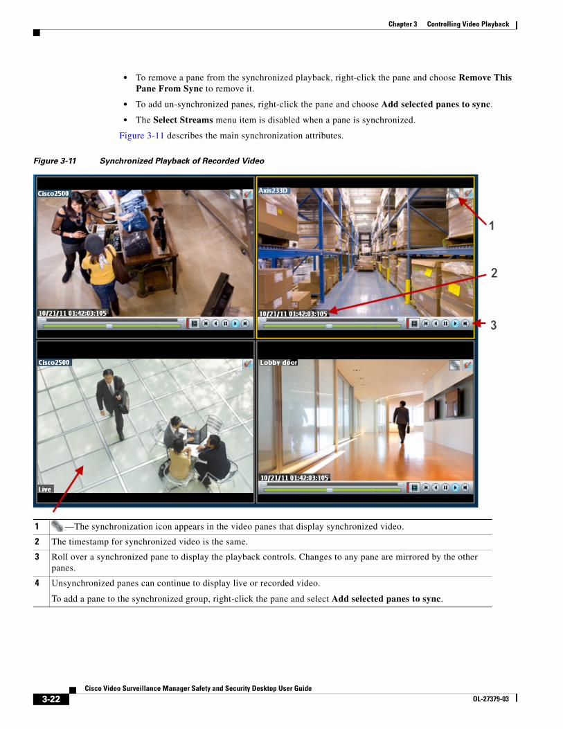
Figure 3-11 describes the main synchronization attributes.
Figure 3-11 Synchronized Playback of Recorded Video
1 —The synchronization icon appears in the video panes that display synchronized video.
2 The timestamp for synchronized video is the same.
3 Roll over a synchronized pane to display the playback controls. Changes to any pane are mirrored by the other panes.
4 Unsynchronized panes can continue to display live or recorded video.
To add a pane to the synchronized group, right-click the pane and select Add selected panes to sync.
3-22Cisco Video Surveillance Manager Safety and Security Desktop User Guide
OL-27379-03
Chapter 3 Controlling Video Playback
Procedure
To play recorded video from multiple video panes synchronized to the same time, do the following:
Step 1 Select a layout or pre-defined view from the View menu.
Step 2 Shift-click or Control-click to select multiple video panes for synchronization.
The selected panes are displayed with a light yellow border.
Step 3 Right-click a video pane and select Sync Selected Panes With This Pane from the menu.
The selected pane becomes the master pane.
Step 4 (Optional) To remove a pane from the synchronized group, right-click the pane and choose Remove This Pane From Sync.
Note The pane continues to play video from the same timestamp, but the video can be stopped or altered without affecting the other panes.
Step 5 (Optional) To add un-synchronized panes, right-click the pane and choose Add selected panes to sync.
3-23Cisco Video Surveillance Manager Safety and Security Desktop User Guide
OL-27379-03
Chapter 3 Controlling Video Playback
Using Pan, Tilt, and Zoom (PTZ) ControlsCameras that support pan, tilt and zoom (PTZ) movements display a PTZ icon . To pan and tilt, left-click the image (the movement icons appear) and drag the mouse right, left, up and down. To zoom, shift-click the image and drag the mouse up and down (to zoom in and out).
You can also use a USB joystick. See the “Calibrating a Joystick for Windows 7” section on page 3-26.
In addition, PTZ presets allow the camera to quickly jump to a preset position. For example, a PTZ preset could zoom in on a doorway, or pan to the opposite end of a parking lot. PTZ presets can be triggered using a mouse, joystick or automatically triggered event.
Note Cameras can also be configured with PTZ tours that automatically cycle between PTZ preset positions. You can interrupt the tour using the PTZ controls, and the tour will resume after a set amount of time. See your system administrator for more information.
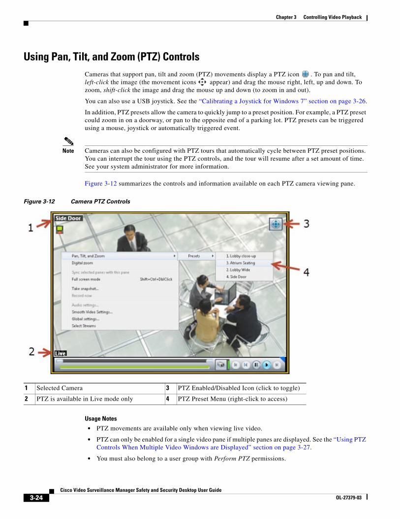
Figure 3-12 summarizes the controls and information available on each PTZ camera viewing pane.
Figure 3-12 Camera PTZ Controls
1 Selected Camera 3 PTZ Enabled/Disabled Icon (click to toggle)
2 PTZ is available in Live mode only 4 PTZ Preset Menu (right-click to access)
Usage Notes
• PTZ movements are available only when viewing live video.
• PTZ can only be enabled for a single video pane if multiple panes are displayed. See the “Using PTZ Controls When Multiple Video Windows are Displayed” section on page 3-27.
• You must also belong to a user group with Perform PTZ permissions.
3-24Cisco Video Surveillance Manager Safety and Security Desktop User Guide
OL-27379-03
Chapter 3 Controlling Video Playback
Procedure
To control a camera’s PTZ movement or trigger a PTZ preset position, do the following:
Step 1 Display the live video from a PTZ-enabled camera:
a. Click Monitor Video.
b. Expand the location tree and select the camera.
c. Highlight a video pane and double-click a camera name.
Step 2 Verify that the PTZ controls are enabled:
• —PTZ controls are supported by the camera and enabled in the viewing pane.
• —PTZ controls are disabled. Click the icon to enable PTZ controls.
Note If a higher-priority user is using the PTZ controls, the PTZ controls remain locked and you cannot control the PTZ movements until released by the higher priority user.
Step 3 To move the camera position, use the following controls.
Using a Mouse
– Pan and Tilt—Left-click the image and drag the mouse ( ) right, left, up and down.
– Zoom—Shift-click the image and drag the mouse ( ) up and down to zoom in and out.
Using a USB Joystick
– Pan—move the joystick bar horizontally.
– Tilt— move the joystick bar vertically.
– Zoom —twist the joystick.
Tip See the “Calibrating a Joystick for Windows 7” section on page 3-26 for information to set up a USB joystick for the first time.
Step 4 (Optional) Select a PTZ preset position.
Using a Mouse
– Right-click the image and choose Pan, Tilt, and Zoom and then Presets (Figure 3-12).
– Choose a preset to move the camera to the defined position.
Using a USB Joystick
– Press the joystick button that corresponds to the PTZ preset number.
– For example, joystick button 1 triggers PTZ preset 1, joystick button 2 triggers PTZ preset 2, etc.
3-25Cisco Video Surveillance Manager Safety and Security Desktop User Guide
OL-27379-03
Chapter 3 Controlling Video Playback
Calibrating a Joystick for Windows 7
To use a USB joystick to control PTZ camera movements, connect the joystick to a USB port on the client PC and calibrate the device for Window 7. You can use the software and instructions included with the joystick, or use the built-in Windows calibration utility, as described in the following procedure.
Procedure
Step 1 Install and configure the USB joystick according to the manufacturer instructions.
• See the device documentation for more information.
• The manufacturer may also include a calibration utility that can be used instead of the built-in Windows utility.
Step 2 In Windows 7, calibrate the device using the Game Controllers control panel.
a. Select Control Panel from the Start menu.
b. Select Hardware and Sound.
c. Select Devices and Printers.
d. Double-click Game Controllers.
e. Highlight the joystick device and click Properties.
f. Click Calibrate in the pop-up window.
g. Follow the on-screen instructions to complete the process.
Tip You can also use the Windows search function: choose Search from the Start menu and enter “set up USB game controllers” to open the Game Controllers control panel. Highlight the joystick icon and click Calibrate. Follow the on-screen instructions to complete the process.
Step 3 Click Finish or OK to close the windows.
3-26Cisco Video Surveillance Manager Safety and Security Desktop User Guide
OL-27379-03
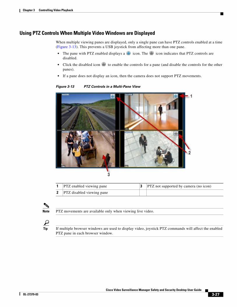
Chapter 3 Controlling Video Playback
Using PTZ Controls When Multiple Video Windows are Displayed
When multiple viewing panes are displayed, only a single pane can have PTZ controls enabled at a time (Figure 3-13). This prevents a USB joystick from affecting more than one pane.
• The pane with PTZ enabled displays a icon. The icon indicates that PTZ controls are disabled.
• Click the disabled icon to enable the controls for a pane (and disable the controls for the other panes).
• If a pane does not display an icon, then the camera does not support PTZ movements.
Figure 3-13 PTZ Controls in a Multi-Pane View
1 PTZ enabled viewing pane 3 PTZ not supported by camera (no icon)
2 PTZ disabled viewing pane
Note PTZ movements are available only when viewing live video.
Tip If multiple browser windows are used to display video, joystick PTZ commands will affect the enabled PTZ pane in each browser window.
3-27Cisco Video Surveillance Manager Safety and Security Desktop User Guide
OL-27379-03

Chapter 3 Controlling Video Playback
3-28Cisco Video Surveillance Manager Safety and Security Desktop User Guide
OL-27379-03
Cisco Video SurveillancOL-27379-03
C H A P T E R 4
Viewing AlertsSelect the Alerts Centric Workspace (Figure 4-1) to view a summary of system alerts and the cameras and events related to each alert (if available). Alerts can include motion events, or device and system health notifications.
You can also do the following:
• Acknowledge, close, or re-open alerts
• Add a comment, or flag the alert as a false alarm.
• View video related to motion and analytics alerts.
Tip Alerts can include multiple events. For example, if the same event occurs repeatedly over time, only a single alerts is generated. Select an alert to view the events associated with that alert.
Contents
• Alert Management Overview, page 4-2
• Common Tasks, page 4-3
• Alert Management Overview, page 4-2
4-1e Manager Safety and Security Desktop User Guide
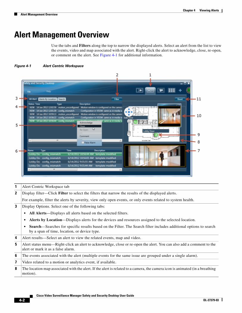
Chapter 4 Viewing AlertsAlert Management Overview
Alert Management OverviewUse the tabs and Filters along the top to narrow the displayed alerts. Select an alert from the list to view the events, video and map associated with the alert. Right-click the alert to acknowledge, close, re-open, or comment on the alert. See Figure 4-1 for additional information.
Figure 4-1 Alert Centric Workspace
1 Alert Centric Workspace tab
2 Display filter—Click Filter to select the filters that narrow the results of the displayed alerts.
For example, filter the alerts by severity, view only open events, or only events related to system health.
3 Display Options. Select one of the following tabs:
• All Alerts—Displays all alerts based on the selected filters.
• Alerts by Location—Displays alerts for the devices and resources assigned to the selected location.
• Search—Searches for specific results based on the Filter. The Search filter includes additional options to search by a span of time, location, or device type.
4 Alert results—Select an alert to view the related events, map and video.
5 Alert status menu—Right-click an alert to acknowledge, close or re-open the alert. You can also add a comment to the alert or mark it as a false alarm.
6 The events associated with the alert (multiple events for the same issue are grouped under a single alarm).
7 Video related to a motion or analytics event, if available.
8 The location map associated with the alert. If the alert is related to a camera, the camera icon is animated (in a breathing motion).
4-2Cisco Video Surveillance Manager Safety and Security Desktop User Guide
OL-27379-03
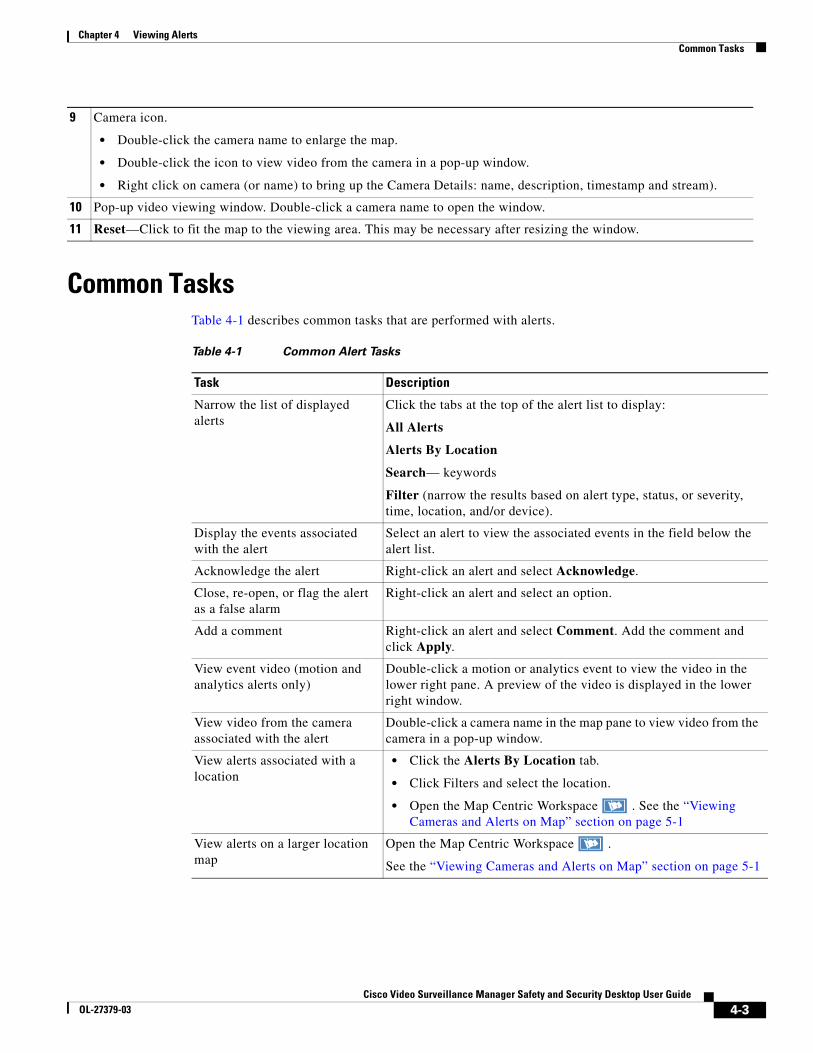
Chapter 4 Viewing AlertsCommon Tasks
Common TasksTable 4-1 describes common tasks that are performed with alerts.
Table 4-1 Common Alert Tasks
Task Description
Narrow the list of displayed alerts
Click the tabs at the top of the alert list to display:
All Alerts
Alerts By Location
Search— keywords
Filter (narrow the results based on alert type, status, or severity, time, location, and/or device).
Display the events associated with the alert
Select an alert to view the associated events in the field below the alert list.
Acknowledge the alert Right-click an alert and select Acknowledge.
Close, re-open, or flag the alert as a false alarm
Right-click an alert and select an option.
Add a comment Right-click an alert and select Comment. Add the comment and click Apply.
View event video (motion and analytics alerts only)
Double-click a motion or analytics event to view the video in the lower right pane. A preview of the video is displayed in the lower right window.
View video from the camera associated with the alert
Double-click a camera name in the map pane to view video from the camera in a pop-up window.
View alerts associated with a location
• Click the Alerts By Location tab.
• Click Filters and select the location.
• Open the Map Centric Workspace . See the “Viewing Cameras and Alerts on Map” section on page 5-1
View alerts on a larger location map
Open the Map Centric Workspace .
See the “Viewing Cameras and Alerts on Map” section on page 5-1
9 Camera icon.
• Double-click the camera name to enlarge the map.
• Double-click the icon to view video from the camera in a pop-up window.
• Right click on camera (or name) to bring up the Camera Details: name, description, timestamp and stream).
10 Pop-up video viewing window. Double-click a camera name to open the window.
11 Reset—Click to fit the map to the viewing area. This may be necessary after resizing the window.
4-3Cisco Video Surveillance Manager Safety and Security Desktop User Guide
OL-27379-03
Chapter 4 Viewing AlertsImpact of Device Location Changes on Alerts
Impact of Device Location Changes on AlertsBecause device locations rarely change, the alert location will normally be the same as the device location. However, if the device location is changed, the following will occur:
• New events show the new location, but are added to the existing (and open) alert at the old location.
• When the alert is closed by an operator, any new events create a new alert at the new location (the location reference in the alert is now consistent with the device location in the event).
For example:
1. Events are added to Alert 1 at the original Location 1:
Alert 1 Location 1 Device 1
Event 99 Location1 device1
Event 98 Location1 device1
Etc.
2. The device location is changed to Location 2.
3. New events generated for an existing (and open) Alert 1 are added to the alert using the new Location 2, but the alert is still associated with the original Location 1.
Alert 1 Location 1 Device 1
Event 101 Location2 device1
Event 100 Location2 device1
Event 99 Location1 device1
Event 98 Location1 device1
Etc.
4. An operator closes the alert (by right-clicking on it).
5. New events are associated with a new alert in the new Location 2 (the location reference in the alert is now consistent with the device location in the event).
Alert 2 Location 2 Device 1
Event 103 Location2 device1
Event 102 Location2 device1
Etc.
4-4Cisco Video Surveillance Manager Safety and Security Desktop User Guide
OL-27379-03

Cisco Video SurveillancOL-27379-03
C H A P T E R 5
Viewing Cameras and Alerts on MapThe Map Centric Workspace (Figure 5-1) displays maps of the region, city, building or other areas where the Cisco VSM is deployed. Click a location to view the associated map, and a list of available cameras for that location. To view video, double-click a camera name to a pop-up viewing window.
5-1e Manager Safety and Security Desktop User Guide
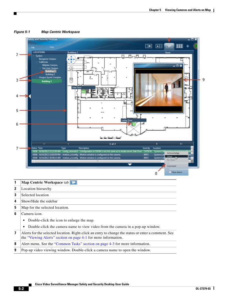
Chapter 5 Viewing Cameras and Alerts on Map
Figure 5-1 Map Centric Workspace
1 Map Centric Workspace tab
2 Location hierarchy
3 Selected location
4 Show/Hide the sidebar
5 Map for the selected location.
6 Camera icon.
• Double-click the icon to enlarge the map.
• Double-click the camera name to view video from the camera in a pop-up window.
7 Alerts for the selected location. Right-click an entry to change the status or enter a comment. See the “Viewing Alerts” section on page 4-1 for more information.
8 Alert menu. See the “Common Tasks” section on page 4-3 for more information.
9 Pop-up video viewing window. Double-click a camera name to open the window.
5-2Cisco Video Surveillance Manager Safety and Security Desktop User Guide
OL-27379-03
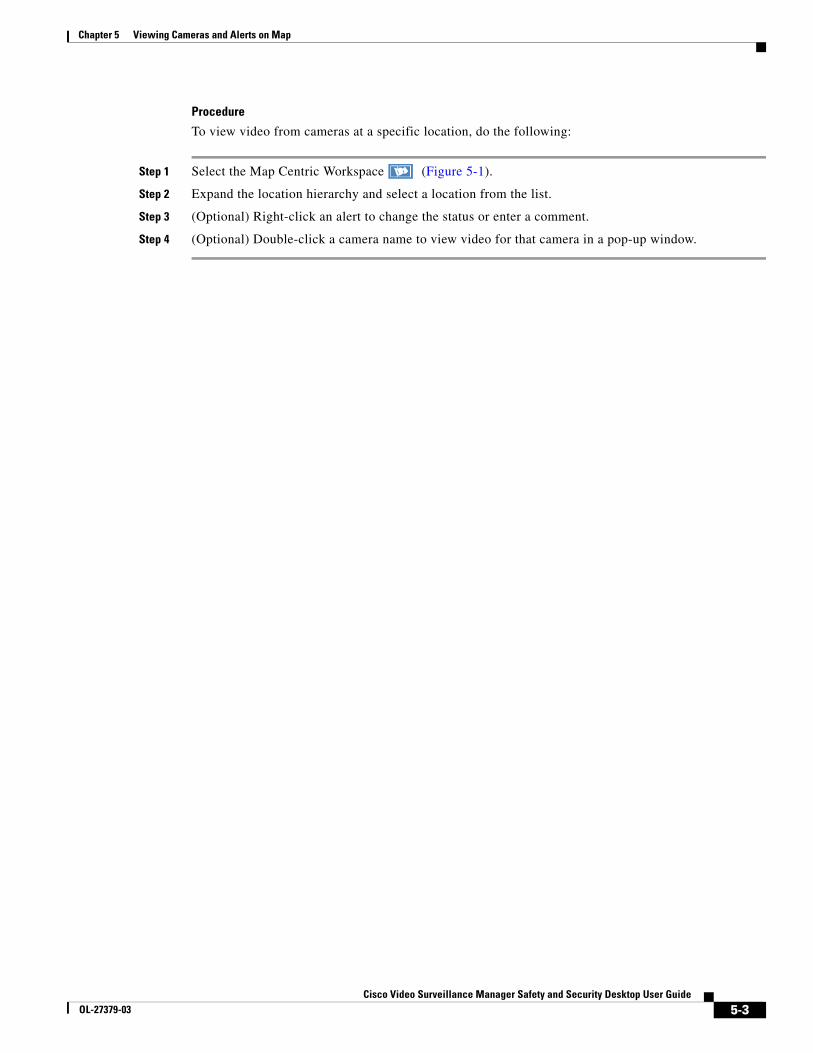
Chapter 5 Viewing Cameras and Alerts on Map
Procedure
To view video from cameras at a specific location, do the following:
Step 1 Select the Map Centric Workspace (Figure 5-1).
Step 2 Expand the location hierarchy and select a location from the list.
Step 3 (Optional) Right-click an alert to change the status or enter a comment.
Step 4 (Optional) Double-click a camera name to view video for that camera in a pop-up window.
5-3Cisco Video Surveillance Manager Safety and Security Desktop User Guide
OL-27379-03

Chapter 5 Viewing Cameras and Alerts on Map
5-4Cisco Video Surveillance Manager Safety and Security Desktop User Guide
OL-27379-03
Cisco Video SurveillancOL-27379-03
C H A P T E R 6
Editing Locations and MapsRefer to the following topics to edit the locations and associated map images displayed in the Cisco Video Surveillance Safety and Security Desktop (Cisco SASD) application.
Contents
• Map Editor Overview, page 6-2
• Editing Locations, page 6-3
• Adding or Updating Map Images, page 6-5
• Placing a Sub-Location on a Map, page 6-6
6-1e Manager Safety and Security Desktop User Guide
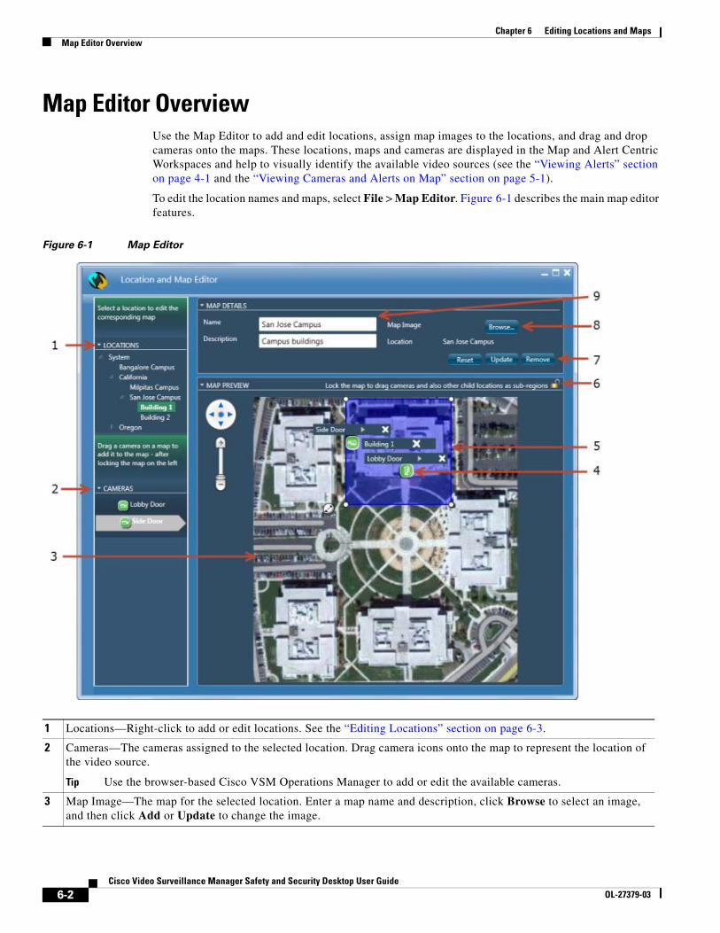
Chapter 6 Editing Locations and MapsMap Editor Overview
Map Editor OverviewUse the Map Editor to add and edit locations, assign map images to the locations, and drag and drop cameras onto the maps. These locations, maps and cameras are displayed in the Map and Alert Centric Workspaces and help to visually identify the available video sources (see the “Viewing Alerts” section on page 4-1 and the “Viewing Cameras and Alerts on Map” section on page 5-1).
To edit the location names and maps, select File > Map Editor. Figure 6-1 describes the main map editor features.
Figure 6-1 Map Editor
1 Locations—Right-click to add or edit locations. See the “Editing Locations” section on page 6-3.
2 Cameras—The cameras assigned to the selected location. Drag camera icons onto the map to represent the location of the video source.
Tip Use the browser-based Cisco VSM Operations Manager to add or edit the available cameras.
3 Map Image—The map for the selected location. Enter a map name and description, click Browse to select an image, and then click Add or Update to change the image.
6-2Cisco Video Surveillance Manager Safety and Security Desktop User Guide
OL-27379-03
Chapter 6 Editing Locations and MapsEditing Locations
Editing LocationsLocations allow you to organize your deployment according to the real-world location of equipment and users. Locations also allow administrators to restrict user access to the specific cameras, policies, and data (such as alerts) required by the user’s role within the organization. For example, while a super-admin has full access to all locations and devices, a local campus administrator might have access only to the devices and policies required to manage that site.
For example, a create a top-level location for a city or region. Then create sub-locations for the cities where Cisco VSM cameras are installed. You can create additional sub-locations for a geographic location, campus, building or other area, such as floors, lobbies, or doors.
Note • The Locations displayed in the Cisco Safety and Security desktop application are the same as those displayed in the web-based Cisco VSOM administration tool. Changes to the Location hierarchy in either application are reflected in both tools. For example, if you add or rename a location using the desktop application, those changes also appear in the web-based administration tool.
• Locations are also edited using the browser-based Cisco VSM Operations Manager. Since Locations are also assigned to cameras, Media Servers, users, and other system attributes, only administrators should add or edit the locations to ensure system integrity.
Procedure
To add or edit a location, right-click a location name and select an option from the menu.
Step 1 Select File > Map Editor.
4 Camera icon—Represents a video source in the map image. Click the lock icon to lock the image ( ) and drag a camera name onto the map image. Click the arrow next to the camera name to rotate the icon.
5 Sub-Location—A clickable area on the map that represents a sub-location. Click the lock icon to lock the image ( ) and drag the sub-location onto the map. Use the tools in the corners and center of the blue box to resize or move the clickable area.
6 Lock icon—Click the lock icon to lock the image ( ) and prevent it from changing when you drag cameras and sub-locations onto the map (sub-locations are clickable areas that appear in the Map Centric Workspace).
7 Reset—Click to fit the map to the viewing area. This may be necessary after resizing the window.
Add—Adds a new map is no map exists for the selected location (click Browse and select an image file from a local or network drive).
Update—Saves changes to the image is a different map is selected or if sub-locations or cameras are added.
Remove—Removes the location image, sub-locations and camera icons.
8 Browse—Identifies the map image file that will be used to Add or Update the image displayed for the location.
The supported file formats are: jpg, jpeg, png, bmp, gif, tiff, and tif.
9 Map name and description.
6-3Cisco Video Surveillance Manager Safety and Security Desktop User Guide
OL-27379-03
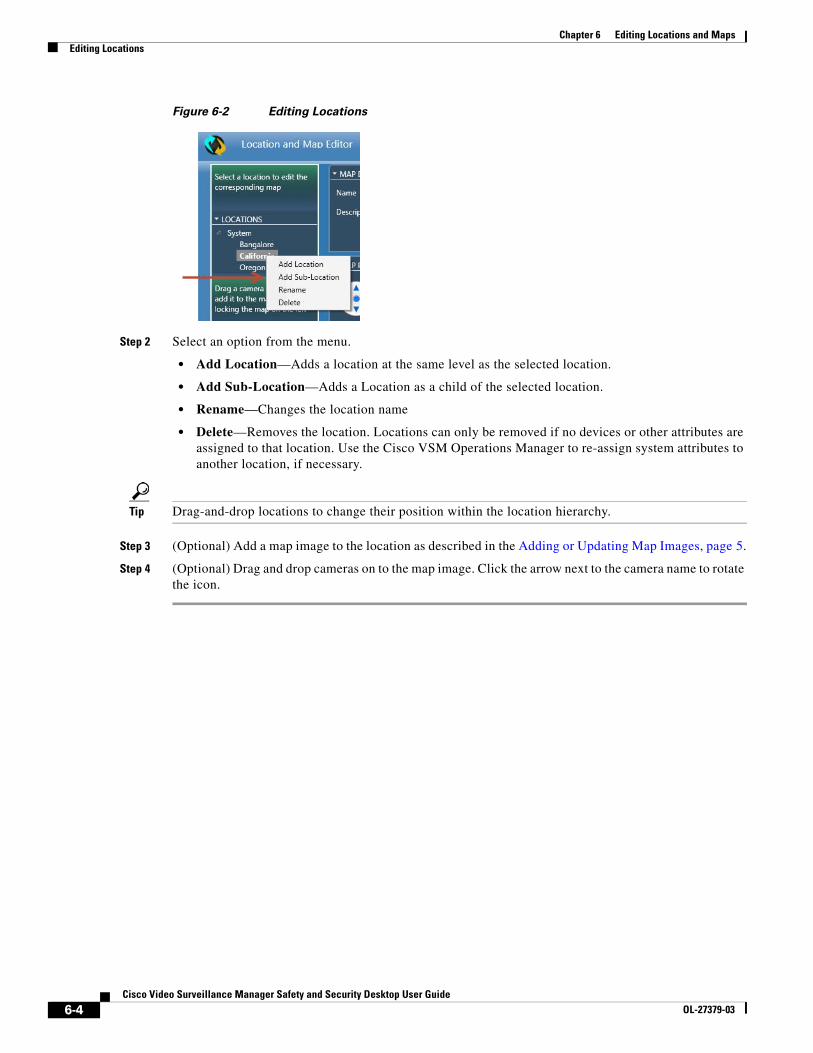
Chapter 6 Editing Locations and MapsEditing Locations
Figure 6-2 Editing Locations
Step 2 Select an option from the menu.
• Add Location—Adds a location at the same level as the selected location.
• Add Sub-Location—Adds a Location as a child of the selected location.
• Rename—Changes the location name
• Delete—Removes the location. Locations can only be removed if no devices or other attributes are assigned to that location. Use the Cisco VSM Operations Manager to re-assign system attributes to another location, if necessary.
Tip Drag-and-drop locations to change their position within the location hierarchy.
Step 3 (Optional) Add a map image to the location as described in the Adding or Updating Map Images, page 5.
Step 4 (Optional) Drag and drop cameras on to the map image. Click the arrow next to the camera name to rotate the icon.
6-4Cisco Video Surveillance Manager Safety and Security Desktop User Guide
OL-27379-03
Chapter 6 Editing Locations and MapsAdding or Updating Map Images
Adding or Updating Map ImagesMap images are assigned to a location, and appear in the Map and Alert Centric Workspaces.
Note The supported file formats are: jpg, jpeg, png, bmp, gif, tiff, and tif.
To add or update the map image for a location, select a location, and then select the map image file that should appear for that location, as shown in Figure 6-1 on page 6-2. You can also enter a name and location for the map image.
Procedure
Step 1 Select File > Map Editor.
Step 2 Select a location.
Step 3 In the Map Details section, define the map image:
a. Enter a name and description for the map image.
b. Click Browse to select a map image file form a local or network drive.
Step 4 (Optional) Drag and drop cameras on to the map image. Click the arrow next to the camera name to rotate the icon.
• Click a location to display the cameras associated with that location.
• Click the arrow next to the camera name to rotate the icon.
Step 5 Click Add or Update.
Tip Click Remove to remove the map image. The map image is removed from the Cisco Safety and Security application, but the image file is not deleted from your hard drive.
Step 6 Continue to the “Placing a Sub-Location on a Map” section on page 6-6.
Related Documentation
• Placing a Sub-Location on a Map, page 6-6
• Viewing Alerts, page 4-1
• Viewing Cameras and Alerts on Map, page 5-1
6-5Cisco Video Surveillance Manager Safety and Security Desktop User Guide
OL-27379-03
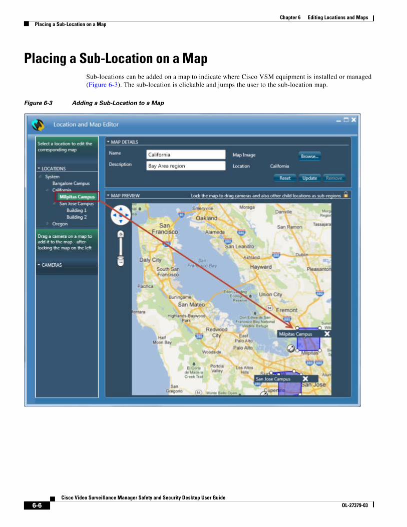
Chapter 6 Editing Locations and MapsPlacing a Sub-Location on a Map
Placing a Sub-Location on a MapSub-locations can be added on a map to indicate where Cisco VSM equipment is installed or managed (Figure 6-3). The sub-location is clickable and jumps the user to the sub-location map.
Figure 6-3 Adding a Sub-Location to a Map
6-6Cisco Video Surveillance Manager Safety and Security Desktop User Guide
OL-27379-03
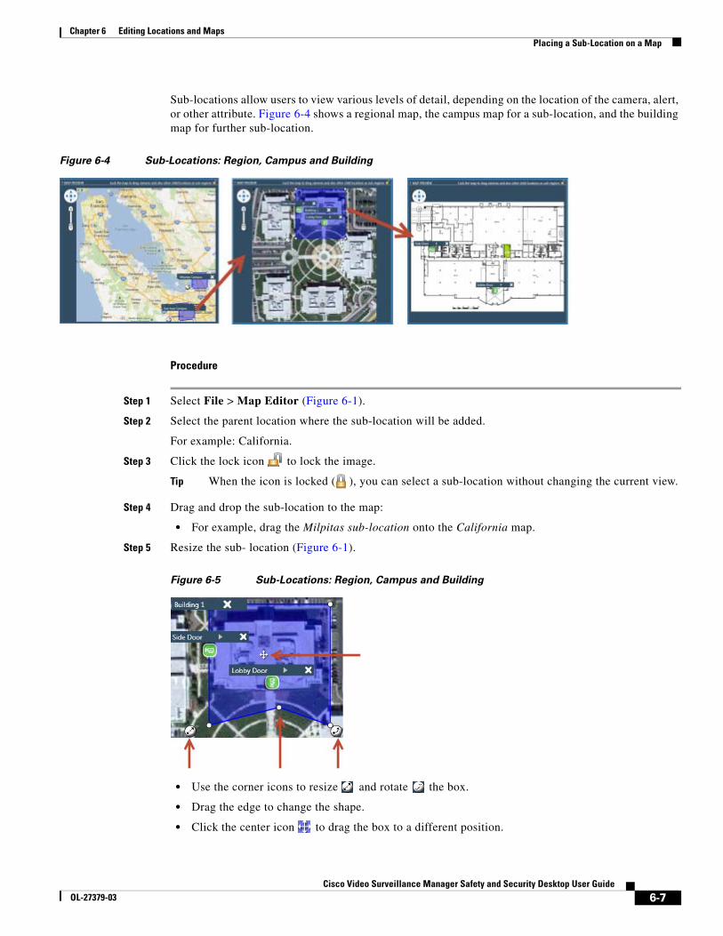
Chapter 6 Editing Locations and MapsPlacing a Sub-Location on a Map
Sub-locations allow users to view various levels of detail, depending on the location of the camera, alert, or other attribute. Figure 6-4 shows a regional map, the campus map for a sub-location, and the building map for further sub-location.
Figure 6-4 Sub-Locations: Region, Campus and Building
Procedure
Step 1 Select File > Map Editor (Figure 6-1).
Step 2 Select the parent location where the sub-location will be added.
For example: California.
Step 3 Click the lock icon to lock the image.
Tip When the icon is locked ( ), you can select a sub-location without changing the current view.
Step 4 Drag and drop the sub-location to the map:
• For example, drag the Milpitas sub-location onto the California map.
Step 5 Resize the sub- location (Figure 6-1).
Figure 6-5 Sub-Locations: Region, Campus and Building
• Use the corner icons to resize and rotate the box.
• Drag the edge to change the shape.
• Click the center icon to drag the box to a different position.
6-7Cisco Video Surveillance Manager Safety and Security Desktop User Guide
OL-27379-03
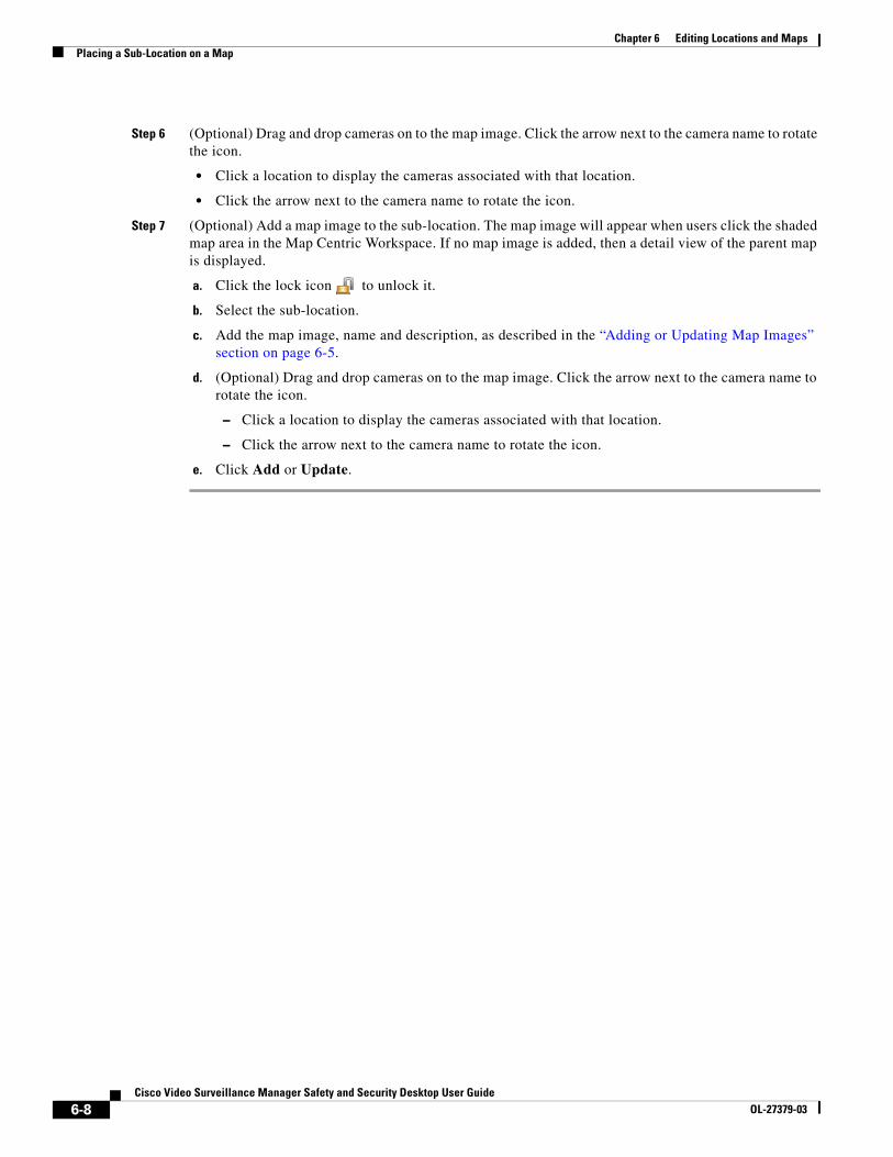
Chapter 6 Editing Locations and MapsPlacing a Sub-Location on a Map
Step 6 (Optional) Drag and drop cameras on to the map image. Click the arrow next to the camera name to rotate the icon.
• Click a location to display the cameras associated with that location.
• Click the arrow next to the camera name to rotate the icon.
Step 7 (Optional) Add a map image to the sub-location. The map image will appear when users click the shaded map area in the Map Centric Workspace. If no map image is added, then a detail view of the parent map is displayed.
a. Click the lock icon to unlock it.
b. Select the sub-location.
c. Add the map image, name and description, as described in the “Adding or Updating Map Images” section on page 6-5.
d. (Optional) Drag and drop cameras on to the map image. Click the arrow next to the camera name to rotate the icon.
– Click a location to display the cameras associated with that location.
– Click the arrow next to the camera name to rotate the icon.
e. Click Add or Update.
6-8Cisco Video Surveillance Manager Safety and Security Desktop User Guide
OL-27379-03
Cisco Video Surveillance ManaOL-27379-03
A
P P E N D I X A Related DocumentationUse one of the following methods to access the Cisco Video Surveillance (Cisco VSM) documentation:
• Click Help at the top of the screen to open the online help system.
• Go to the Cisco Video Surveillance documentation web site (the documents and direct links are summarized below).
Documentation Summary and Links
Refer to the following documentation for additional information about Cisco Video Surveillance, including server installation, system configuration, video monitoring, and other features.
Topic Related Document Description
All Documents Cisco Video Surveillance documentation web site
Links to all of the documents described in this table.
Release Notes Release Notes for Cisco Video Surveillance Manager, Release 7.0
Describes the new and changed features, open and resolved caveats, and other information.
Server installation Cisco Physical Security Multiservices Platform Series User Guide
Instructions to physically install and set up the Cisco VSM server appliance. Each server can run the Media Server application, the Operations Manager application, or both.
Management Console Cisco Video Surveillance Management Console Administration Guide
Use the browser-based Cisco VSM Management Console to set up and maintain a Cisco VSM server. Tasks include server software and driver pack upgrades, Media Server backups.
Browser-based configuration and monitoring
Cisco Video Surveillance Operations Manager User Guide
Use the browser-based Operations Manager to configure and manage a Cisco VSM deployment.
The Operation Manager can also be used to monitor live and recorded video.
Workstation video monitoring
Cisco Video Surveillance Safety and Security Desktop User Guide
Use the Cisco Video Surveillance Safety and Security Desktop (Cisco SASD) application to view cameras, video and alerts on a graphical map. You can also display a video grid on a separate monitor, view Video Walls on multiple workstations, or create unattended workstations.
Video clip player Cisco Video Surveillance Review Player User Guide
Use the Cisco VSM Review Player desktop application for basic playback of multi-pane video clips.
A-1ger Safety and Security Desktop User Guide
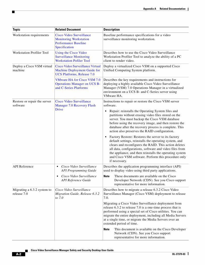
Appendix A Related Documentation
Workstation requirements Cisco Video Surveillance Monitoring Workstation Performance Baseline Specification
Baseline performance specifications for a video surveillance monitoring workstation.
Workstation Profiler Tool Using the Cisco Video Surveillance Monitoring Workstation Pofiler Tool
Describes how to use the Cisco Video Surveillance Workstation Profiler Tool to analyze the ability of a PC client to render video.
Deploy a Cisco VSM virtual machine
Cisco Video Surveillance Virtual Machine Deployment Guide for UCS Platforms, Release 7.0
Deploy a virtualized Cisco VSM on a supported Cisco Unified Computing System platform.
VMware HA for Cisco VSM 7.0 Operations Manager on UCS B- and C-Series Platforms
Describes the key requirements and instructions for deploying a highly available Cisco Video Surveillance Manager (VSM) 7.0 Operations Manager in a virtualized environment on a UCS B- and C-Series server using VMware HA.
Restore or repair the server software
Cisco Video Surveillance Manager 7.0 Recovery Flash Drive
Instructions to repair or restore the Cisco VSM server software.
• Repair: reinstalls the Operating System files and partitions without erasing video files stored on the server. You must backup the Cisco VSM database before using the recovery image, and then restore the database after the recovery process is complete. This action also preserves the RAID configuration.
• Factory Restore: Restores the server to its factory default settings, reinstalls the operating system, and clears and reconfigures the RAID. This action deletes all data, configurations, software and video files from the appliance, and then reinstalls the operating system and Cisco VSM software. Perform this procedure only if necessary.
API Reference • Cisco Video Surveillance API Programming Guide
• Cisco Video Surveillance API Reference Guide
Describes the application programming interface (API) used to display video using third party applications.
Note These documents are available on the Cisco Developer Network (CDN). See you Cisco support representative for more information.
Migrating a 6.3.2 system to release 7.0
Cisco Video Surveillance Migration Guide, Release 6.3.2 to 7.0
Describes how to migrate a release 6.3.2 Cisco Video Surveillance Manager (Cisco VSM) deployment to release 7.0.
Migrating a Cisco Video Surveillance deployment from release 6.3.2 to release 7.0 is a one-time process that is performed using a special set of Cisco utilities. You can migrate the entire deployment, including all Media Servers at a single time, or migrate the Media Servers over an extended period of time.
Note This document is available on the Cisco Developer Network (CDN). See you Cisco support representative for more information.
Topic Related Document Description
A-2Cisco Video Surveillance Manager Safety and Security Desktop User Guide
OL-27379-03

Appendix A Related Documentation
A-3Cisco Video Surveillance Manager Safety and Security Desktop User Guide
OL-27379-03