Embed Size (px)
Citation preview
OL-14435-01
C H A P T E R 8
Cisco Wireless Mesh NetworkingThis document provides design and deployment guidelines for the deployment of secure enterprise, campus, and metropolitan Wi-Fi networks within the Cisco Wireless Mesh Networking solution, a component of the Cisco Unified Wireless Network solution.
Note For more detailed information about Cisco Wireless Mesh Networking, including configuration and deployment, refer to the Cisco Mesh Access Points, Design and Deployment Guide, Release 7.3 at http://www.cisco.com/en/US/docs/wireless/technology/mesh/7.3/design/guide/Mesh.html.
Mesh networking employs Cisco Aironet 1500 Series outdoor mesh access points (APs) and indoor mesh APs (Cisco Aironet 1040, 1130, 1140, 1240, 1250, 1260, 2600, 3500e, 3500i, 3600e, and 3600i series APs) along with the Cisco Wireless LAN Controller (WLC), and Cisco Prime Infrastructure to provide scalable, central management and mobility between indoor and outdoor deployments. Control and Provisioning of Wireless Access Points (CAPWAP) protocol manages the connection of the mesh APs to the network.
End-to-end security within the mesh network is supported by employing Advanced Encryption Standard (AES) encryption between the wireless mesh APs and Wi-Fi Protected Access 2 (WPA2) clients. This document also outlines radio frequency (RF) components to consider when designing an outdoor network.
The features described in this document are for the following products:
• Cisco Aironet 1550 (1552) Series outdoor 802.11n mesh APs
• Cisco Aironet 1520 (1522, 1524) Series outdoor mesh APs
• Cisco Aironet 1040, 1130, 1140, 1240, 1250, 1260, 2600, 3500e, 3500i, 3600e, and 3600i series indoor mesh APs
• Mesh features in Cisco Wireless LAN Controller
• Mesh features in Cisco Prime Infrastructure
Note Cisco Aironet 1505 and 1510 mesh APs are not supported because of their End-of-Life status.
8-1Enterprise Mobility 7.3 Design Guide
Chapter 8 Cisco Wireless Mesh Networking
Access Point RolesAccess points (APs) within a mesh network operate in one of the following two ways:
• Root AP (RAP)
• Mesh AP (MAP)
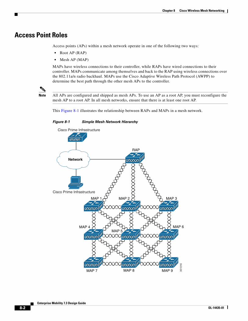
MAPs have wireless connections to their controller, while RAPs have wired connections to their controller. MAPs communicate among themselves and back to the RAP using wireless connections over the 802.11a/n radio backhaul. MAPs use the Cisco Adaptive Wireless Path Protocol (AWPP) to determine the best path through the other mesh APs to the controller.
Note All APs are configured and shipped as mesh APs. To use an AP as a root AP, you must reconfigure the mesh AP to a root AP. In all mesh networks, ensure that there is at least one root AP.
This Figure 8-1 illustrates the relationship between RAPs and MAPs in a mesh network.
Figure 8-1 Simple Mesh Network Hierarchy
3510
16
Cisco Prime Infrastructure
Cisco Prime Infrastructure
Network
RAP
MAP 1 MAP 2 MAP 3
MAP 4 MAP 6MAP 5
MAP 7 MAP 8 MAP 9
8-2Enterprise Mobility 7.3 Design Guide
OL-14435-01
Chapter 8 Cisco Wireless Mesh NetworkingCisco Indoor Mesh Access Points
Network AccessWireless mesh networks can simultaneously carry two different traffic types. They are as follows:
• Wireless LAN client traffic
• MAP Ethernet port traffic
Wireless LAN client traffic terminates on the controller, and the Ethernet traffic terminates on the Ethernet ports of the mesh APs.
Access to the wireless LAN mesh for mesh APs is managed by the following authentication methods:
• MAC authentication—Mesh APs are added to a database that can be referenced to ensure they are provided access to a given controller and mesh network.
• External RADIUS Authentication—Mesh APs can be externally authorized using a RADIUS server such as Cisco ACS (4.1 and later) that supports the client authentication type of Identity Services Engine (ISE) or Extensible Authentication Protocol-FAST (EAP-FAST) with certificates.
Network SegmentationMembership to the wireless LAN mesh network for mesh APs is controlled by the bridge group names (BGNs). Mesh APs can be placed in similar bridge groups to manage membership or provide network segmentation.
Cisco Indoor Mesh Access PointsIndoor mesh is available on the following APs. The list shows the 802.11 protocol supported by each group of APs:
• 802.11a/b/g
– 1130
– 1240
• 802.11n
– 1040
– 1140
– 1250
– 1260
• 802.11n+CleanAir
– 2600
– 3500e
– 3500i
– 3600
8-3Enterprise Mobility 7.3 Design Guide
OL-14435-01
Chapter 8 Cisco Wireless Mesh NetworkingCisco Outdoor Mesh Access Points
Note For more information about controller software support for APs, see the Cisco Wireless Solutions Software Compatibility Matrix at: http://www.cisco.com/en/US/docs/wireless/controller/5500/tech_notes/Wireless_Software_Compatibility_Matrix.html.
Enterprise 11n mesh is an enhancement added to the Cisco Unified Wireless Network feature to work with the 802.11n APs. Enterprise 11n mesh features are compatible with non-802.11n mesh but add higher backhaul and client access speeds. The 802.11n indoor APs are two-radio Wi-Fi infrastructure devices for select indoor deployments. One radio can be used for local (client) access for the AP and the other radio can be configured for wireless backhaul. The backhaul is supported only on the 5-GHz radio. Enterprise 11n mesh supports P2P, P2MP, and mesh types of architectures.
You have a choice of ordering indoor APs directly in the bridge mode so that these APs can be used directly as mesh APs. If you have these APs in a local mode (nonmesh), then you have to connect these APs to the controller and change the AP mode to the bridge mode (mesh). This scenario can become cumbersome particularly if the volume of the APs being deployed is large and if the APs are already deployed in the local mode for a traditional nonmesh wireless coverage.
The Cisco indoor mesh APs are equipped with the following two simultaneously operating ratios:
• 2.4-GHz radio used for client access
• 5-GHz radio used for data backhaul
Cisco Outdoor Mesh Access PointsCisco outdoor mesh APs comprise of the Cisco Aironet 1500 series APs. The 1500 series includes 1552 11n outdoor mesh APs, 1522 dual radio mesh APs, and 1524 multi-radio mesh APs. There are two 1524 models; public safety and 1524PS.
Note In the 6.0 release, the AP1524SB AP was launched in A, C, and N domains. In the 7.0 release, the AP1524SB AP was launched in the -E, -M, -K, -S, and -T domains.
Cisco 1500 series mesh APs are the core components of the wireless mesh deployment. AP1500s are configured by both the controller (GUI and CLI) and Cisco Prime Infrastructure. Communication between outdoor mesh APs (MAPs and RAPs) is over the 802.11a/n radio backhaul. Client traffic is generally transmitted over the 802.11b/g/n radio (802.11a/n can also be configured to accept client traffic), and public safety traffic (AP1524PS only) is transmitted over the 4.9-GHz radio.
The mesh AP can also operate as a relay node for other APs not directly connected to a wired network. Intelligent wireless routing is provided by the Adaptive Wireless Path Protocol (AWPP). This Cisco protocol enables each mesh AP to identify its neighbors and intelligently choose the optimal path to the wired network by calculating the cost of each path in terms of the signal strength and the number of hops required to get to a controller.
8-4Enterprise Mobility 7.3 Design Guide
OL-14435-01
Chapter 8 Cisco Wireless Mesh NetworkingCisco Outdoor Mesh Access Points
AP1500s are manufactured in two different configurations: cable and non-cable.
• The cable configuration can be mounted to a cable strand and supports power-over-cable (POC).
• The non-cable configuration supports multiple antennas. It can be mounted to a pole or building wall and supports several power options.
Uplinks support includes Gigabit Ethernet (1000BASE-T) and a small form-factor (SFP) slot that can be plugged for a fiber or cable modem interface. Both single mode and multimode SFPs up to 1000BASE-BX are supported. The cable modem can be DOCSIS 2.0 or DOCSIS/EuroDOCSIS 3.0 depending upon the type of mesh AP.
AP1500s are available in a hazardous location hardware enclosure. When configured, the AP1500 complies with safety standards for Class I, Division 2, Zone 2 hazardous locations.
The 1520 and 1550 series APs can operate apart from the mesh mode, in the following modes:
• Local mode—In this mode, the AP can handle clients on its assigned channel or while monitoring all channels on the band over a 180-second period. During this time, the AP listens on each channel for 50 milliseconds for rogue client beacons, noise floor measurements, interference, and IDS events. The AP also scans for CleanAir interference on the channel.
• FlexConnect mode—FlexConnect is a wireless solution for branch office and remote office deployments. The FlexConnect mode enables you to configure and control APs in a branch or remote office from the corporate office through a WAN link without having to deploy a controller in each office. The FlexConnect mode can switch client data traffic locally and perform client authentication locally when the connection to the controller is lost. When connected to the controller, the FlexConnect mode can also tunnel traffic back to the controller.
• Monitor mode—In this mode, the AP radios are in the receive state. The AP scans all of the channels every 12 seconds for rogue client beacons, noise floor measurements, interference, IDS events, and CleanAir intruders.
• Rogue Detector mode—In this mode, the AP radio is turned off, and the AP listens only to the wired traffic. The controller passes the APs that are configured as rogue detectors as well as lists of suspected rogue clients and AP MAC addresses. The rogue detector listens for ARP packets and can be connected to all broadcast domains through a trunk link.
• Sniffer mode—In this mode, the AP captures and forwards all packets on a channel to a remote device that decodes the packets with packet analyzer software such as Wireshark.
Cisco Aironet 1552 Mesh Access PointThe Cisco Aironet 1550 Series Outdoor Mesh Access Point is a modularized wireless outdoor 802.11n AP designed for use in a mesh network. The AP supports point-to-multipoint mesh wireless connectivity and wireless client access simultaneously. The AP can also operate as a relay node for other APs that are not directly connected to a wired network. Intelligent wireless routing is provided by the Adaptive Wireless Path Protocol (AWPP). This enables the AP to identify its neighbors and intelligently choose the optimal path to the wired network by calculating the cost of each path in terms of signal strength and the number of hops required to get to a controller.
The 1550 series APs leverage 802.11n technology with integrated radio and internal/external antennas. The 1552 outdoor platform consists of Multiple Input Multiple Output (MIMO) WLAN radios. It offers 2x3 MIMO with two spatial streams and beamforming, and comes with integrated spectrum intelligence (CleanAir).
CleanAir provides full 11n data rates while detecting, locating, classifying, and mitigating radio frequency (RF) interference to provide the best client experience possible. CleanAir technology on the outdoor 11n platform mitigates Wi-Fi and non-Wi-Fi interference on 2.4-GHz radios.
8-5Enterprise Mobility 7.3 Design Guide
OL-14435-01
Chapter 8 Cisco Wireless Mesh NetworkingCisco Outdoor Mesh Access Points
The 1550 series APs have two radios: 2.4-GHz and 5-GHz MIMO radios. While the 2.4-GHz radios are used primarily for local access, the 5-GHz radios are used for both local access and wireless backhaul in mesh mode.
Note The 2.4-GHz radios cannot be used for backhaul in 1552 APs.
The 2.4-GHz b/g/n radio has the following features:
• Operates in the 2.4-GHz ISM band.
• Supports channels 1-11 in the United States, 1-13 in Europe, and 1-13 in Japan.
• Has two transmitters for 802.11b/g/n operation.
• You can configure the output power for 5 power levels.
• The radio has three receivers that enable maximum-ratio combining (MRC).
The 5-GHz a/n radio has the following feature:
• Operates in the UNII-2 band (5.25 to 5.35 GHz), UNII-2 Extended/ETSI band (5.47 to 5.725 GHz), and the upper ISM band (5.725 to 5.850 GHz).
• Has two transmitters for 802.11a operation.
• Power settings can change depending on the regulatory domain. You can configure the output power for 5 power levels in 3 dB steps.
• The radio has three receivers that enable maximum-ratio combining (MRC).
The 1550 series APs have the following features:
• Supports modularity of the 1520 series and allows flexibility in radio configuration
• Fully interoperable with the 1520 series APs
• Can also interoperate with legacy clients and offers enhanced backhaul performance
• Multicast VideoStream is supported when the AP is configured in Local mode.
• HotSpot 2.0 is supported when the AP is configured in Local / FlexConnect / Mesh mode
• AP1552 is QoS capable of supporting quality VoWLAN calls.
• Band select, which notifies a connected client to roam from 2.4 GHz to 5 GHz, is supported.
• DTLS support allows AP1552 to encrypt data in all supported AP modes except bridge mode.
• You can enable CleanAir on the 5-GHz radio by navigating to Wireless > Radios > 802.11a > Configure on the controller GUI.
Cisco 1522 Mesh Access PointThe AP1522 mesh AP (part numbers: AIR–LAP1522AG–X–K9, AIR–LAP1522HZ–X–K9, AIR–LAP1522PC–X–K9) includes two radios: a 2.4-GHz and a 4.9- to 5.8-GHz radio. The 2.4-GHz (802.11b/g) radio is for client access and the 5-GHz (802.11a) radio is used as the backhaul. With the 7.0.116.0 release and later releases, 2.4 GHz is available for backhaul. This feature is applicable only to AP1522.
The 5-GHz radio is a 802.11a radio that covers the 4.9- to 5.8-GHz frequency band and is used as a backhaul. It can also be used for client access if the universal client access feature is enabled.
8-6Enterprise Mobility 7.3 Design Guide
OL-14435-01
Chapter 8 Cisco Wireless Mesh NetworkingEthernet Ports
Cisco 1524SB Mesh Access PointThe AP1524SB mesh AP (part number: AIR–LAP1524SB–X–K9) includes three radios: one 2.4-GHz radio and two 5-GHz radios.
The 2.4-GHz radio is for client access (nonpublic safety traffic). The two 5-GHz radios serve as serial backhauls: one uplink and one downlink. The AP1524SB is suitable for linear deployments.
Note In the 6.0 release, the 5-GHz radios in the –A domain could be operated only in the 5.8-GHz band with 5 channels. In the 7.0 release, these radios cover the whole 5-GHz band.
Each 5-GHz radio backhaul is configured with a different backhaul channel. There is no need to use the same shared wireless medium between the north-bound and south-bound traffic in a mesh tree-based network.
On the RAP, the radio in slot 2 is used to extend the backhaul in the downlink direction; the radio in slot 1 is used only for client access and not mesh.
On the MAP, the radio in slot 2 is used for the backhaul in the uplink direction; the radio in slot 1 is used for the backhaul in the downlink direction.
You only need to configure the RAP downlink (slot 2) channel. The MAPs automatically select their channels from the channel subset. The available channels for the 5.8-GHz band are 149, 153, 157, 161, and 165.
Ethernet PortsAP1500s support four Gigabit Ethernet interfaces.
• Port 0 (g0) is a Power over Ethernet (PoE) input port–PoE (in)
• Port 1 (g1) is a PoE output port–PoE (out)
• Port 2 (g2) is a cable connection
• Port 3 (g3) is a fiber connection
You can query the status of these four interfaces in the controller CLI and Cisco Prime Infrastructure.
In the controller CLI, the show mesh env summary command is used to display the status of the ports. The Up or Down (Dn) status of the four ports is reported in the following format:
port0(PoE-in):port1(PoE-out):port2(cable):port3(fiber)
For example, rap1522.a380 in the display below shows a port status of UpDnDnDn. This indicates the following:
PoE-in port 0 (g0) is Up, PoE-out port 1 (g1) is Down (Dn), Cable port 2 (g2) is Down (Dn), and Fiber port 3 (g3) is Down (Dn)
(controller)> show mesh env summaryAP Name Temperature(C/F) Heater Ethernet Battery----------------------- -------- ------- -------- -------rap1242.c9ef N/A N/A UP N/Arap1522.a380 29/84 OFF UpDnDnDn N/Arap1522.4da8 31/87 OFF UpDnDnDn N/A
8-7Enterprise Mobility 7.3 Design Guide
OL-14435-01
Chapter 8 Cisco Wireless Mesh Networking1550 Series Multiple Power Options
1550 Series Multiple Power OptionsPower options include the following:
Power over Ethernet (PoE)-In
• 56 VDC using a Power Injector (1552E and 1552H)
• PoE-In is not 802.3af and does not work with PoE 802.3af-capable Ethernet switch
AC Power
• 100 to 480 VAC (47-63 Hz)—Connecting AC or Streetlight Power (1552E)
• 100 to 240 VAC—Connecting AC or Streetlight Power (1552H)
External Supply
• 12 VDC—Connecting DC Power Cable (All Models)
Internal Battery Backup (1552E and 1552H)
Power over Cable (PoC)
• 40 to 90VAC—Connecting Cable PoC (1552C)
PoE-Out 802.3af compliant to connect IP devices such as Video Cameras (1552E and 1552H)
• (PoE-Out) is not available when using Power Injector (PoE-In) as the power source
802.3af compliant PoE-Out to connect IP devices such as video cameras (1552E and 1552H)
• This port also performs Auto-MDIX, which enables to connect crossover or straight through cables.
The 1550 series APs can be connected to more than one power source. The APs detect the available power sources and switch to the preferred power source using the following default prioritization:
• AC power or PoC power
• External 12-VDC power
• Power injector PoE power
• Internal battery power
Cisco Wireless LAN ControllersThe wireless mesh solution is supported on Cisco 2500, 5500, and 8500 Series Wireless LAN Controllers. For more information about these controllers, see:
http://www.cisco.com/en/US/products/ps6302/Products_Sub_Category_Home.html.
Cisco Prime InfrastructureThe Cisco Prime Infrastructure provides a graphical platform for wireless mesh planning, configuration, and management. Network managers can use the Cisco Prime Infrastructure to design, control, and monitor wireless mesh networks from a central location.
8-8Enterprise Mobility 7.3 Design Guide
OL-14435-01
Chapter 8 Cisco Wireless Mesh NetworkingArchitecture
With the Cisco Prime Infrastructure, network administrators have a solution for RF prediction, policy provisioning, network optimization, troubleshooting, user tracking, security monitoring, and wireless LAN systems management. Graphical interfaces make wireless LAN deployment and operations simple and cost-effective. Detailed trending and analysis reports make the Cisco Prime Infrastructure vital to ongoing network operations.
The Cisco Prime Infrastructure runs on a server platform with an embedded database, which provides scalability that allows hundreds of controllers and thousands of Cisco mesh APs to be managed. Controllers can be located on the same LAN as the Cisco Prime Infrastructure, on separate routed subnets, or across a wide-area connection.
Architecture
Control and Provisioning of Wireless Access PointsControl and Provisioning of Wireless Access Points (CAPWAP) is the protocol used by the controller to manage APs (mesh and nonmesh) in the network. In release 5.2, CAPWAP replaced the lightweight AP protocol (LWAPP).
Note CAPWAP significantly reduces capital expenditures (CapEx) and operational expenses (OpEx), which enables the Cisco wireless mesh networking solution to be a cost-effective and secure deployment option in enterprise, campus, and metropolitan networks.
CAPWAP Discovery on a Mesh NetworkThe process for CAPWAP discovery on a mesh network is as follows:
1. A mesh AP establishes a link before starting CAPWAP discovery, whereas a nonmesh AP starts CAPWAP discovery using a static IP for the mesh AP, if any.
2. The mesh AP initiates CAPWAP discovery using a static IP for the mesh AP on the Layer 3 network or searches the network for its assigned primary, secondary, or tertiary controller. A maximum of 10 attempts are made to connect.
Note The mesh AP searches a list of controllers configured on the AP (primed) during setup.
3. If Step 2 fails after 10 attempts, the mesh AP falls back to DHCP and attempts to connect in 10 tries.
4. If both Steps 2 and 3 fail and there is no successful CAPWAP connection to a controller, then the mesh AP falls back to LWAPP.
5. If there is no discovery after attempting Steps 2, 3, and 4, the mesh AP tries the next link.
Adaptive Wireless Path ProtocolThe Adaptive Wireless Path Protocol (AWPP) is designed specifically for wireless mesh networking to provide ease of deployment, fast convergence, and minimal resource consumption.
8-9Enterprise Mobility 7.3 Design Guide
OL-14435-01
Chapter 8 Cisco Wireless Mesh NetworkingAdaptive Wireless Path Protocol
AWPP takes advantage of the CAPWAP WLAN, where client traffic is tunneled to the controller and is therefore hidden from the AWPP process. Also, the advance radio management features in the CAPWAP WLAN solution are available to the wireless mesh network and do not have to be built into AWPP.
AWPP enables a remote AP to dynamically find the best path back to a RAP for each MAP that is part of the RAP’s bridge group (BGN). Unlike traditional routing protocols, AWPP takes RF details into account.
To optimize the route, a MAP actively solicits neighbor MAP. During the solicitation, the MAP learns all of the available neighbors back to a RAP, determines which neighbor offers the best path, and then synchronizes with that neighbor. The path decisions of AWPP are based on the link quality and the number of hops.
AWPP automatically determines the best path back to the CAPWAP controller by calculating the cost of each path in terms of the signal strength and number of hops. After the path is established, AWPP continuously monitors conditions and changes routes to reflect changes in conditions. AWPP also performs a smoothing function to signal condition information to ensure that the ephemeral nature of RF environments does not impact network stability.
Traffic FlowThe traffic flow within the wireless mesh can be divided into three components:
1. Overlay CAPWAP traffic that flows within a standard CAPWAP AP deployment; that is, CAPWAP traffic between the CAPWAP AP and the CAPWAP controller.
2. Wireless mesh data frame flow.
3. AWPP exchanges.
As the CAPWAP model is well known and the AWPP is a proprietary protocol, only the wireless mesh data flow is described. The key to the wireless mesh data flow is the address fields of the 802.11 frames being sent between mesh APs.
An 802.11 data frame can use up to four address fields: receiver, transmitter, destination, and source. The standard frame from a WLAN client to an AP uses only three of these address fields because the transmitter address and the source address are the same. However, in a WLAN bridging network, all four address fields are used because the source of the frame might not be the transmitter of the frame, because the frame might have been generated by a device behind the transmitter.
8-10Enterprise Mobility 7.3 Design Guide
OL-14435-01
Chapter 8 Cisco Wireless Mesh NetworkingMesh Neighbors, Parents, and Children
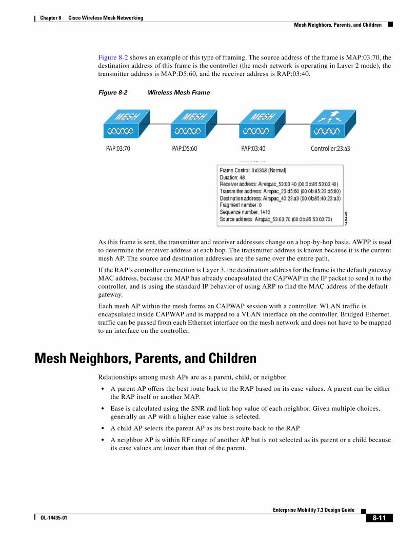
Figure 8-2 shows an example of this type of framing. The source address of the frame is MAP:03:70, the destination address of this frame is the controller (the mesh network is operating in Layer 2 mode), the transmitter address is MAP:D5:60, and the receiver address is RAP:03:40.
Figure 8-2 Wireless Mesh Frame
As this frame is sent, the transmitter and receiver addresses change on a hop-by-hop basis. AWPP is used to determine the receiver address at each hop. The transmitter address is known because it is the current mesh AP. The source and destination addresses are the same over the entire path.
If the RAP’s controller connection is Layer 3, the destination address for the frame is the default gateway MAC address, because the MAP has already encapsulated the CAPWAP in the IP packet to send it to the controller, and is using the standard IP behavior of using ARP to find the MAC address of the default gateway.
Each mesh AP within the mesh forms an CAPWAP session with a controller. WLAN traffic is encapsulated inside CAPWAP and is mapped to a VLAN interface on the controller. Bridged Ethernet traffic can be passed from each Ethernet interface on the mesh network and does not have to be mapped to an interface on the controller.
Mesh Neighbors, Parents, and ChildrenRelationships among mesh APs are as a parent, child, or neighbor.
• A parent AP offers the best route back to the RAP based on its ease values. A parent can be either the RAP itself or another MAP.
• Ease is calculated using the SNR and link hop value of each neighbor. Given multiple choices, generally an AP with a higher ease value is selected.
• A child AP selects the parent AP as its best route back to the RAP.
• A neighbor AP is within RF range of another AP but is not selected as its parent or a child because its ease values are lower than that of the parent.
PAP:03:70 PAP:D5:60 PAP:03:40 Controller:23:a3
8-11Enterprise Mobility 7.3 Design Guide
OL-14435-01
Chapter 8 Cisco Wireless Mesh NetworkingMesh Neighbors, Parents, and Children
Criteria to Choose the Best ParentAWPP follows this process in selecting parents for a RAP or MAP with a radio backhaul:
• A list of channels with neighbors is generated by passive scanning in the scan state, which is a subset of all backhaul channels.
• The channels with neighbors are sought by actively scanning in the seek state, and the backhaul channel is changed to the channel with the best neighbor.
• The parent is set to the best neighbor, and the parent-child handshake is completed in the seek state.
• Parent maintenance and optimization occurs in the maintain state.
This algorithm is run at startup and whenever a parent is lost and no other potential parent exists, and is usually followed by CAPWAP network and controller discovery. All neighbor protocol frames carry the channel information.
Parent maintenance occurs by the child node sending a directed NEIGHBOR_REQUEST to the parent and the parent responding with a NEIGHBOR_RESPONSE.
Parent optimization and refresh occurs by the child node sending a NEIGHBOR_REQUEST broadcast on the same channel on which its parent resides, and by evaluating all responses from neighboring nodes on the channel.
A parent mesh AP provides the best path back to a RAP. AWPP uses ease to determine the best path. Ease can be considered the opposite of cost, and the preferred path is the path with the higher ease.
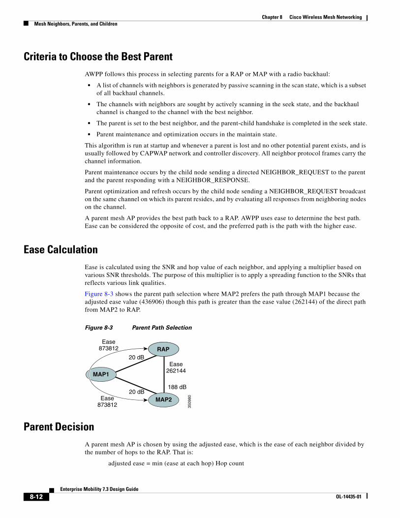
Ease CalculationEase is calculated using the SNR and hop value of each neighbor, and applying a multiplier based on various SNR thresholds. The purpose of this multiplier is to apply a spreading function to the SNRs that reflects various link qualities.
Figure 8-3 shows the parent path selection where MAP2 prefers the path through MAP1 because the adjusted ease value (436906) though this path is greater than the ease value (262144) of the direct path from MAP2 to RAP.
Figure 8-3 Parent Path Selection
Parent DecisionA parent mesh AP is chosen by using the adjusted ease, which is the ease of each neighbor divided by the number of hops to the RAP. That is:
adjusted ease = min (ease at each hop) Hop count
3509
80
MAP1
RAP
MAP2Ease873812
Ease873812
Ease262144
20 dB
20 dB188 dB
8-12Enterprise Mobility 7.3 Design Guide
OL-14435-01
Chapter 8 Cisco Wireless Mesh NetworkingMesh Deployment Modes
Mesh Deployment ModesIn a Cisco wireless outdoor mesh network, multiple mesh APs comprise a network that provides secure, scalable outdoor wireless LAN.
The three RAPs are connected to the wired network at each location and are located on the building roof. All the downstream APs operate as MAPs and communicate using wireless links (not shown).
Both MAPs and RAPs can provide WLAN client access; however, the location of RAPs are often not suitable for providing client access. All the three APs in are located on the building roofs and are functioning as RAPs. These RAPs are connected to the network at each location.
Some of the buildings have onsite controllers to terminate CAPWAP sessions from the mesh APs but it is not a mandatory requirement because CAPWAP sessions can be back hauled to a controller over a wide-area network (WAN).
Wireless BackhaulIn a Cisco wireless backhaul network, traffic can be bridged between MAPs and RAPs. This traffic can be from wired devices that are being bridged by the wireless mesh or CAPWAP traffic from the mesh APs. This traffic is always AES encrypted when it crosses a wireless mesh link such as a wireless backhaul.
AES encryption is established as part of the mesh AP neighbor relationship with other mesh APs. The encryption keys used between mesh APs are derived during the EAP authentication process.
Only 5 GHz backhaul is possible on all mesh APs except 1522 in which either 2.4 or 5 GHz radio can be configured as a backhaul radio (see Configuring Advanced Features).
Universal AccessYou can configure the backhaul on mesh APs to accept client traffic over its 802.11a radio. This feature is identified as Backhaul Client Access in the controller GUI (Monitor > Wireless). When this feature is disabled, backhaul traffic is transmitted only over the 802.11a or 802.11a/n radio and client association is allowed only over the 802.11b/g or 802.11b/g/n radio. For more information about the configuration, see the Configuring Advanced Features.
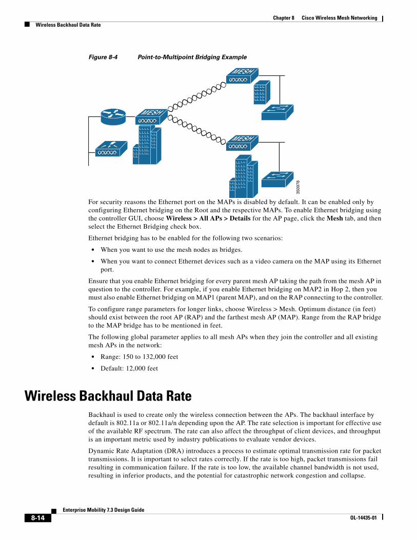
Point-to-Multipoint Wireless BridgingIn the point-to-multipoint bridging scenario, a RAP acting as a root bridge connects multiple MAPs as nonroot bridges with their associated wired LANs. By default, this feature is disabled for all MAPs. If Ethernet bridging is used, you must enable it on the controller for the respective MAP and for the RAP.
Figure 8-4 shows a simple deployment with one RAP and two MAPs, but this configuration is fundamentally a wireless mesh with no WLAN clients. Client access can still be provided with Ethernet bridging enabled, although if bridging between buildings, MAP coverage from a high rooftop might not be suitable for client access.
8-13Enterprise Mobility 7.3 Design Guide
OL-14435-01
Chapter 8 Cisco Wireless Mesh NetworkingWireless Backhaul Data Rate
Figure 8-4 Point-to-Multipoint Bridging Example
For security reasons the Ethernet port on the MAPs is disabled by default. It can be enabled only by configuring Ethernet bridging on the Root and the respective MAPs. To enable Ethernet bridging using the controller GUI, choose Wireless > All APs > Details for the AP page, click the Mesh tab, and then select the Ethernet Bridging check box.
Ethernet bridging has to be enabled for the following two scenarios:
• When you want to use the mesh nodes as bridges.
• When you want to connect Ethernet devices such as a video camera on the MAP using its Ethernet port.
Ensure that you enable Ethernet bridging for every parent mesh AP taking the path from the mesh AP in question to the controller. For example, if you enable Ethernet bridging on MAP2 in Hop 2, then you must also enable Ethernet bridging on MAP1 (parent MAP), and on the RAP connecting to the controller.
To configure range parameters for longer links, choose Wireless > Mesh. Optimum distance (in feet) should exist between the root AP (RAP) and the farthest mesh AP (MAP). Range from the RAP bridge to the MAP bridge has to be mentioned in feet.
The following global parameter applies to all mesh APs when they join the controller and all existing mesh APs in the network:
• Range: 150 to 132,000 feet
• Default: 12,000 feet
Wireless Backhaul Data RateBackhaul is used to create only the wireless connection between the APs. The backhaul interface by default is 802.11a or 802.11a/n depending upon the AP. The rate selection is important for effective use of the available RF spectrum. The rate can also affect the throughput of client devices, and throughput is an important metric used by industry publications to evaluate vendor devices.
Dynamic Rate Adaptation (DRA) introduces a process to estimate optimal transmission rate for packet transmissions. It is important to select rates correctly. If the rate is too high, packet transmissions fail resulting in communication failure. If the rate is too low, the available channel bandwidth is not used, resulting in inferior products, and the potential for catastrophic network congestion and collapse.
3509
78
8-14Enterprise Mobility 7.3 Design Guide
OL-14435-01
Chapter 8 Cisco Wireless Mesh NetworkingClientLink Technology
Data rates also affect the RF coverage and network performance. Lower data rates, for example 6 Mbps, can extend farther from the AP than can higher data rates, for example 300 Mbps. As a result, the data rate affects cell coverage and consequently the number of APs required. Different data rates are achieved by sending a more redundant signal on the wireless link, allowing data to be easily recovered from noise. The number of symbols sent out for a packet at the 1-Mbps data rate is higher than the number of symbols used for the same packet at 11 Mbps. Therefore, sending data at the lower bit rates takes more time than sending the equivalent data at a higher bit rate, resulting in reduced throughput.
A lower bit rate might allow a greater distance between MAPs, but there are likely to be gaps in the WLAN client coverage, and the capacity of the backhaul network is reduced. An increased bit rate for the backhaul network either requires more MAPs or results in a reduced SNR between MAPs, limiting mesh reliability and interconnection.
ClientLink TechnologyMany networks still support a mix of 802.11a/g and 802.11n clients. Because 802.11a/g clients (legacy clients) operate at lower data rates, the older clients can reduce the capacity of the entire network. Cisco’s ClientLink technology can help solve problems related to adoption of 802.11n in mixed-client networks by ensuring that 802.11a/g clients operate at the best possible rates, especially when they are near cell boundaries.
Advanced signal processing has been added to the Wi-Fi chipset. Multiple transmit antennas are used to focus transmissions in the direction of the 802.11a/g client, increasing the downlink signal-to-noise ratio and the data rate over range, thereby reducing coverage holes and enhancing the overall system performance. This technology learns the optimum way to combine the signal received from a client and then uses this information to send packets in an optimum way back to the client. This technique is also referred to as Multiple-input multiple-output (MIMO) beamforming, transmit beamforming, or cophasing, and it is the only enterprise-class and service provider-class solution in the market that does not require expensive antenna arrays.
The 802.11n systems take advantage of multipath by sending multiple radio signals simultaneously. Each of these signals, called a spatial stream, is sent from its own antenna using its own transmitter. Because there is some space between these antennas, each signal follows a slightly different path to the receiver, a situation called spatial diversity. The receiver has multiple antennas as well, each with its own radio that independently decodes the arriving signals, and each signal is combined with signals from the other receiver radios. This results in multiple data streams receiving at the same time. This enables a higher throughput than previous 802.11a/g systems, but requires an 802.11n capable client to decipher the signal. Therefore, both AP and client need to support this capability. Due to the complexity of issues, in the first generation of mainstream 802.11n chipsets, neither the AP nor client chipsets implemented 802.11n transmit beamforming. Therefore, the 802.11n standard transmit beamforming will be available eventually, but not until the next generation of chipsets take hold in the market. We intend to lead in this area going forward.
We realized that for the current generation of 802.11n APs, while the second transmit path was being well utilized for 802.11n clients (to implement spatial diversity), it was not being fully used for 802.11a/g clients. In other words, for 802.11 a/g clients, some of the capabilities of the extra transmit path was lying idle. In addition, we realized that for many networks, the performance of the installed 802.11 a/g client base would be a limiting factor on the network.
To take advantage of this fallow capacity and greatly enhance overall network capacity by bringing 802.11 a/g clients up to a higher performance level, we created an innovation in transmit beamforming technology, called ClientLink.
8-15Enterprise Mobility 7.3 Design Guide
OL-14435-01
Chapter 8 Cisco Wireless Mesh NetworkingController Planning
ClientLink uses advanced signal processing techniques and multiple transmit paths to optimize the signal received by 802.11a/g clients in the downlink direction without requiring feedback. Because no special feedback is required, Cisco ClientLink works with all existing 802.11a/g clients.
Cisco ClientLink technology effectively enables the AP to optimize the SNR exactly at the position where the client is placed. ClientLink provides a gain of almost 4 dB in the downlink direction. Improved SNR yields many benefits, such as a reduced number of retries and higher data rates. For example, a client at the edge of the cell that might previously have been capable of receiving packets at 12 Mbps could now receive them at 36 Mbps. Typical measurements of downlink performance with ClientLink show as much as 65 percent greater throughput for 802.11a/g clients. By allowing the Wi-Fi system to operate at higher data rates and with fewer retries, ClientLink increases the overall capacity of the system, which means an efficient use of spectrum resources.
ClientLink in the 1552 APs is based on ClientLink capability available in AP3500s. Therefore, the AP has the ability to beamform well to nearby clients and to update beamforming information on 802.11ACKs. Therefore, even if there is no dedicated uplink traffic, the ClientLink works well, which is beneficial to both TCP and UDP traffic streams. There are no RSSI watermarks, which the client has to cross to take advantage of this beamforming with Cisco 802.11n APs.
ClientLink can beamform to 15 clients at a time. Therefore, the host must select the best 15 if the number of legacy clients exceeds 15 per radio. AP1552 has two radios, which means that up to 30 clients can be beamformed in time domain.
Although ClientLink is applied to legacy OFDM portions of packets, which refers to 11a/g rates (not 11b) for both indoor and outdoor 802.11n APs, there is one difference between ClientLink for indoor 11n and ClientLink for outdoor 11n. For indoor 11n APs, SW limits the affected rates to 24, 36, 48, and 54 Mbps. This is done to avoid clients sticking to a faraway AP in an indoor environment. SW also does not allow ClientLink to work for those rates for 11n clients because the throughput gain is so minimal. However, there is a demonstrable gain for pure legacy clients. For outdoor 11n APs, we do need more coverage. Thus, three more additional legacy data rates lower than 24 Mbps have been added. ClientLink for outdoors is applicable to legacy data rates of 6, 9, 12, 18, 24, 36, 48, and 54 Mbps.
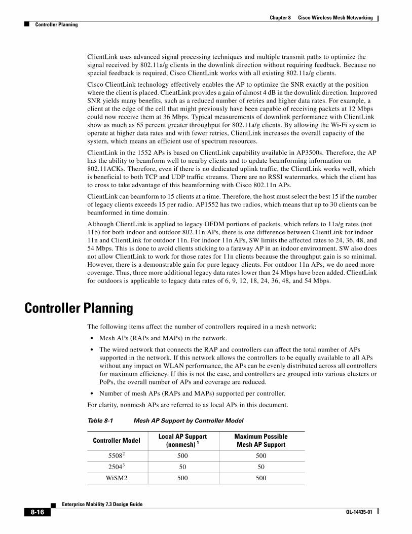
Controller PlanningThe following items affect the number of controllers required in a mesh network:
• Mesh APs (RAPs and MAPs) in the network.
• The wired network that connects the RAP and controllers can affect the total number of APs supported in the network. If this network allows the controllers to be equally available to all APs without any impact on WLAN performance, the APs can be evenly distributed across all controllers for maximum efficiency. If this is not the case, and controllers are grouped into various clusters or PoPs, the overall number of APs and coverage are reduced.
• Number of mesh APs (RAPs and MAPs) supported per controller.
For clarity, nonmesh APs are referred to as local APs in this document.
Table 8-1 Mesh AP Support by Controller Model
Controller Model Local AP Support (nonmesh) 1
Maximum PossibleMesh AP Support
55082 500 500
25043 50 50
WiSM2 500 500
8-16Enterprise Mobility 7.3 Design Guide
OL-14435-01
Chapter 8 Cisco Wireless Mesh NetworkingWireless Mesh Network Coverage Considerations
Note Mesh is fully supported on Cisco 5508 Controllers. The Base License (LIC-CT508-Base) is sufficient for indoor and outdoor APs (AP152X). The WPlus License (LIC-WPLUS-SW) is merged with the base license. The WPlus License is not required for indoor mesh APs.
Wireless Mesh Network Coverage ConsiderationsThis section provides a summary of items that must be considered for maximum wireless LAN coverage in an urban or suburban area, to adhere to compliance conditions for respective domains.
The following recommendations assume a flat terrain with no obstacles (green field deployment).
We always recommend that you perform a site survey before taking any real estimations for the area and creating a bill of materials.
Cell Planning and Distance
For the Cisco 1520 Series Access Points
The RAP-to-MAP ratio is the starting point. For general planning purposes, the current ratio is 20 MAPs per RAP.
We recommend the following values for cell planning and distance in non-voice networks:
• RAP-to-MAP ratio—Recommended maximum ratio is 20 MAPs per RAP.
• AP-to-AP distance—A spacing of no more than of 2000 feet (609.6 meters) between each mesh AP is recommended. When you extend the mesh network on the backhaul (no client access), use a cell radius of 1000 feet (304.8 meters).
• Hop count—Three to four hops. One square mile in feet (52802), is nine cells and you can cover one square mile with approximately three or four hops.
• For 2.4 GHz, the local access cell size radius is 600 feet (182.88 meters). One cell size is around 1.310 x 10⁶, so there are 25 cells per square mile.
Collocating Mesh Access PointsThe following recommendations provide guidelines to determine the required antenna separation when you collocate AP1500s on the same tower. The recommended minimum separations for antennas, transmit powers, and channel spacing are addressed.
The goal of proper spacing and antenna selection is to provide sufficient isolation by way of antenna radiation pattern, free space path loss, and adjacent or alternate adjacent channel receiver rejection to provide independent operation of the collocated units. The goal is to have negligible throughput degradation due to a CCA hold-off, and negligible receive sensitivity degradation due to a receive noise floor increase.
1. Local AP support is the total number of nonmesh APs supported on the controller model.
2. For 5508, controllers, the number of MAPs is equal to (local AP support - number of RAPs).
3. For 2504, controllers, the number of MAPs is equal to (local AP support - number of RAPs).
8-17Enterprise Mobility 7.3 Design Guide
OL-14435-01
Chapter 8 Cisco Wireless Mesh NetworkingCleanAir
You must follow antenna proximity requirements, which depend upon the adjacent and alternate adjacent channel usage.
Collocating AP1500s on Adjacent ChannelsIf two collocated AP1500s operate on adjacent channels such as channel 149 (5745 MHz) and channel 152 (5765 MHz), the minimum vertical separation between the two AP1500s is 40 feet (12.192 meters) (the requirement applies for mesh APs equipped with either 8 dBi omnidirectional or 17 dBi high-gain directional patch antennas).
If two collocated AP1500s operate on channels 1, 6, or 11 (2412 to 2437 MHz) with a 5.5-dBi omnidirectional antenna, then the minimum vertical separation is 8 feet (2.438 meters).
Collocating AP1500s on Alternate Adjacent ChannelsIf two collocated AP1500s operate on alternate adjacent channels such as channel 149 (5745 MHz) and channel 157 (5785 MHz), the minimum vertical separation between the two AP1500s is 10 feet (3.048 meters) (the requirements applies for mesh APs equipped with either 8-dBi omnidirectional or 17-dBi high-gain directional patch antennas).
If two collocated AP1500s operate on alternate adjacent channels 1 and 11 (2412 MHz and 2462 MHz) with a 5.5-dBi omnidirectional antenna, then the minimum vertical separation is 2 feet (0.609 meters).
In summary, a 5-GHz antenna isolation determines mesh AP spacing requirements and antenna proximity must be followed and is dependent upon the adjacent and alternate adjacent channel usage.
CleanAirThe 1550 series leverages 802.11n technology with integrated radio and internal/external antennas. The 1550 series APs are based on the same chipset as the present CleanAir capable Aironet 3500 APs. In other words, the 1550 series APs are capable of doing CleanAir.
With the 7.3.101.0 release, 2600 series APs can mesh with each other and can also provide CleanAir functionality.
With the 7.2.103.0 release, 3600 series APs can mesh with each other and can also provide CleanAir functionality.
With the 7.0.116.0 release, 3500 series APs can mesh with each other and can also provide CleanAir functionality.
CleanAir in mesh (1552, 2600, 3500 and 3600) can be implemented on the 2.4-GHz radio and provides clients complete 802.11n data rates while detecting, locating, classifying, and mitigating radio frequency (RF) interference. This provides a carrier class management and customer experience and ensures that you have control over the spectrum in the deployed location. CleanAir enabled RRM technology on the outdoor 11n platform detects, quantifies, and mitigates Wi-Fi and non-Wi-Fi interference on 2.4-GHz radios. AP1552 supports CleanAir in 2.4 GHz client access mode.
8-18Enterprise Mobility 7.3 Design Guide
OL-14435-01
Chapter 8 Cisco Wireless Mesh NetworkingWireless Mesh Mobility Groups
CleanAir AdvisorIf CleanAir is enabled on a backhaul radio, CleanAir Advisor is activated. CleanAir Advisor generates Air Quality Index (AQI) and Interferer Detection Reports (IDR) but the reports are only displayed in the controller. No action is taken through event driven RRM (ED-RRM). CleanAir Advisor is only present on the 5-GHz backhaul radio of APs in bridge mode.
Wireless Mesh Mobility GroupsA mobility group allows controllers to peer with each other to support seamless roaming across controller boundaries. APs learn the IP addresses of the other members of the mobility group after the CAPWAP Join process. A controller can be a member of a single mobility group which can contain up to 24 controllers. Mobility is supported across 72 controllers. There can be up to 72 members (WLCs) in the mobility list with up to 24 members in the same mobility group (or domain) participating in client hand-offs. The IP address of a client does not have to be renewed in the same mobility domain. Renewing the IP address is irrelevant in the controller-based architecture when you use this feature.
Multiple ControllersThe consideration in distance of the CAPWAP controllers from other CAPWAP controllers in the mobility group, and the distance of the CAPWAP controllers from the RAP, is similar to the consideration of an CAPWAP WLAN deployment in an enterprise.
There are operational advantages to centralizing CAPWAP controllers, and these advantages need to be traded off against the speed and capacity of the links to the CAPWAP APs and the traffic profile of the WLAN clients using these mesh APs.
If the WLAN client traffic is expected to be focused on particular sites, such as the Internet or a data center, centralizing the controllers at the same sites as these traffic focal points gives the operational advantages without sacrificing traffic efficiency.
If the WLAN client traffic is more peer-to-peer, a distributed controller model might be a better fit. It is likely that a majority of the WLAN traffic are clients in the area, with a smaller amount of traffic going to other locations. Given that many peer-to-peer applications can be sensitive to delay and packet loss, you should ensure that traffic between peers takes the most efficient path.
Given that most deployments see a mix of client-server traffic and peer-to peer traffic, it is likely that a hybrid model of CAPWAP controller placement is used, where points of presence (PoPs) are created with clusters of controllers placed in strategic locations in the network.
The CAPWAP model used in the wireless mesh network is designed for campus networks; that is, it expects a high-speed, low-latency network between the CAPWAP mesh APs and the CAPWAP controller.
Increasing Mesh AvailabilityIn the Cell Planning Distance section, a wireless mesh cell of one square mile was created and then built upon. This wireless mesh cell has similar properties to the cells used to create a cellular phone network because the smaller cells (rather than the defined maximum cell size) can be created to cover the same physical area, providing greater availability or capacity. This process is done by adding a RAP to the cell. Similar to the larger mesh deployment, the decision is whether to use RAP on the same channel, as
8-19Enterprise Mobility 7.3 Design Guide
OL-14435-01
Chapter 8 Cisco Wireless Mesh NetworkingIncreasing Mesh Availability
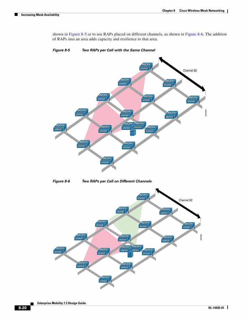
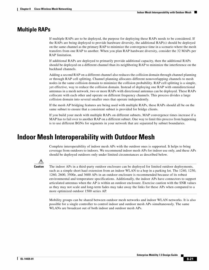
shown in Figure 8-5 or to use RAPs placed on different channels, as shown in Figure 8-6. The addition of RAPs into an area adds capacity and resilience to that area.
Figure 8-5 Two RAPs per Cell with the Same Channel
Figure 8-6 Two RAPs per Cell on Different Channels
Channel B2
35
09
81
Channel B2350982
8-20Enterprise Mobility 7.3 Design Guide
OL-14435-01
Chapter 8 Cisco Wireless Mesh NetworkingIndoor Mesh Interoperability with Outdoor Mesh
Multiple RAPsIf multiple RAPs are to be deployed, the purpose for deploying these RAPs needs to be considered. If the RAPs are being deployed to provide hardware diversity, the additional RAP(s) should be deployed on the same channel as the primary RAP to minimize the convergence time in a scenario where the mesh transfers from one RAP to another. When you plan RAP hardware diversity, consider the 32 MAPs per RAP limitation.
If additional RAPs are deployed to primarily provide additional capacity, then the additional RAPs should be deployed on a different channel than its neighboring RAP to minimize the interference on the backhaul channels.
Adding a second RAP on a different channel also reduces the collision domain through channel planning or through RAP cell splitting. Channel planning allocates different nonoverlapping channels to mesh nodes in the same collision domain to minimize the collision probability. RAP cell splitting is a simple, yet effective, way to reduce the collision domain. Instead of deploying one RAP with omnidirectional antennas in a mesh network, two or more RAPs with directional antennas can be deployed. These RAPs collocate with each other and operate on different frequency channels. This process divides a large collision domain into several smaller ones that operate independently.
If the mesh AP bridging features are being used with multiple RAPs, these RAPs should all be on the same subnet to ensure that a consistent subnet is provided for bridge clients.
If you build your mesh with multiple RAPs on different subnets, MAP convergence times increase if a MAP has to fail over to another RAP on a different subnet. One way to limit this process from happening is to use different BGNs for segments in your network that are separated by subnet boundaries.
Indoor Mesh Interoperability with Outdoor MeshComplete interoperability of indoor mesh APs with the outdoor ones is supported. It helps to bring coverage from outdoors to indoors. We recommend indoor mesh APs for indoor use only, and these APs should be deployed outdoors only under limited circumstances as described below.
Caution The indoor APs in a third-party outdoor enclosure can be deployed for limited outdoor deployments, such as a simple short haul extension from an indoor WLAN to a hop in a parking lot. The 1240, 1250, 1260, 2600, 3500e, and 3600 APs in an outdoor enclosure is recommended because of its robust environmental and temperature specifications. Additionally, the indoor APs have connectors to support articulated antennas when the AP is within an outdoor enclosure. Exercise caution with the SNR values as they may not scale and long-term fades may take away the links for these APs when compared to a more optimized outdoor 1500 series AP.
Mobility groups can be shared between outdoor mesh networks and indoor WLAN networks. It is also possible for a single controller to control indoor and outdoor mesh APs simultaneously. The same WLANs are broadcast out of both indoor and outdoor mesh APs.
8-21Enterprise Mobility 7.3 Design Guide
OL-14435-01
Chapter 8 Cisco Wireless Mesh NetworkingConnecting the Cisco 1500 Series Mesh APs to the Network
Connecting the Cisco 1500 Series Mesh APs to the NetworkThis section describes how to connect the Cisco 1500 Series mesh APs to the network.
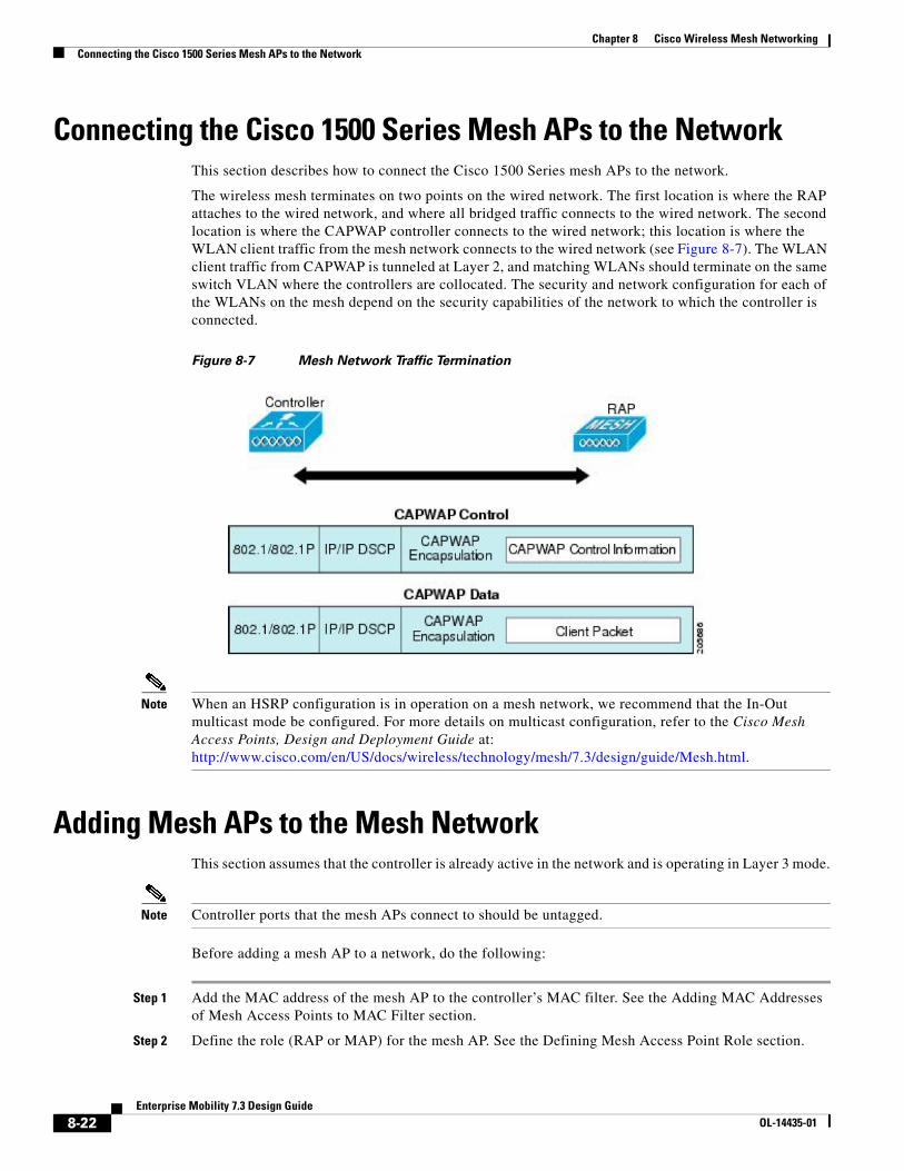
The wireless mesh terminates on two points on the wired network. The first location is where the RAP attaches to the wired network, and where all bridged traffic connects to the wired network. The second location is where the CAPWAP controller connects to the wired network; this location is where the WLAN client traffic from the mesh network connects to the wired network (see Figure 8-7). The WLAN client traffic from CAPWAP is tunneled at Layer 2, and matching WLANs should terminate on the same switch VLAN where the controllers are collocated. The security and network configuration for each of the WLANs on the mesh depend on the security capabilities of the network to which the controller is connected.
Figure 8-7 Mesh Network Traffic Termination
Note When an HSRP configuration is in operation on a mesh network, we recommend that the In-Out multicast mode be configured. For more details on multicast configuration, refer to the Cisco Mesh Access Points, Design and Deployment Guide at: http://www.cisco.com/en/US/docs/wireless/technology/mesh/7.3/design/guide/Mesh.html.
Adding Mesh APs to the Mesh NetworkThis section assumes that the controller is already active in the network and is operating in Layer 3 mode.
Note Controller ports that the mesh APs connect to should be untagged.
Before adding a mesh AP to a network, do the following:
Step 1 Add the MAC address of the mesh AP to the controller’s MAC filter. See the Adding MAC Addresses of Mesh Access Points to MAC Filter section.
Step 2 Define the role (RAP or MAP) for the mesh AP. See the Defining Mesh Access Point Role section.
8-22Enterprise Mobility 7.3 Design Guide
OL-14435-01
Chapter 8 Cisco Wireless Mesh NetworkingAdding Mesh APs to the Mesh Network
Step 3 Verify that Layer 3 is configured on the controller.
Step 4 Configure a primary, secondary, and tertiary controller for each mesh AP. Configure a backup controller. See the Configuring Backup Controllers section.
Step 5 Configure external authentication of MAC addresses using an external RADIUS server. See the Configuring External Authentication and Authorization Using a RADIUS Server.
Step 6 Configure global mesh parameters.
Step 7 Configure universal client access.
Step 8 Configure local mesh parameters.
Step 9 Configure antenna parameters.
Step 10 Configure channels for serial backhaul. This step is applicable only to serial backhaul APs.
Step 11 Configure the DCA channels for the mesh APs.
Step 12 Configure mobility groups (if desired) and assign controllers.
Step 13 Configure Ethernet bridging (if desired).
Step 14 Configure advanced features such as Ethernet VLAN tagging network, video, and voice.
8-23Enterprise Mobility 7.3 Design Guide
OL-14435-01

Chapter 8 Cisco Wireless Mesh NetworkingAdding Mesh APs to the Mesh Network
8-24Enterprise Mobility 7.3 Design Guide
OL-14435-01