Embed Size (px)
DESCRIPTION
Citrix XenServer and NetApp
Citation preview
Citrix XenServer and NetApp Storage Best Practices
Citrix Systems, Inc. and NetApp, Inc.
February 2014 | TR-3732 | Rev 5.3
www.citrix.com
Citrix XenServer and NetApp Storage Best Practices
2
Contents
Chapter 1: Getting Started ................................................................................................................................ 8
Overview of Citrix XenServer ...................................................................................................................... 8
Overview of NetApp Storage Solutions ..................................................................................................... 8
Assumptions ................................................................................................................................................... 9
Configuration Requirements ........................................................................................................................ 9
NetApp Storage Requirements ................................................................................................................................. 9
XenServer Requirements ........................................................................................................................................... 9
Chapter 2: Overview of XenServer Storage .................................................................................................11
Configuring Access to Storage ...................................................................................................................11
Virtual Disk Images (VDIs) ........................................................................................................................12
Configuring Storage Repositories Using XenCenter ..............................................................................12
Shared iSCSI Storage ................................................................................................................................................ 13
Shared Fibre Channel Storage ................................................................................................................................ 14
Shared NAS using NFS ........................................................................................................................................... 14
Chapter 3: NetApp Configuration and Setup ..............................................................................................15
Configuring the NetApp Management Network ....................................................................................15
Obtaining the IP address for a NetApp Storage Controller ..................................................................16
Configuring a NetApp VIF ........................................................................................................................16
Configuring a NetApp Aggregate ..............................................................................................................20
Configuring a Volume .................................................................................................................................23
Choosing Thin Provisioning or Thick Provisioning ........................................................................................... 24
Reclaiming Space with NetApp Deduplication ................................................................................................... 25
Creating a Volume .................................................................................................................................................... 27
Creating an Initiator Group ........................................................................................................................28
Chapter 4: XenServer Storage Best Practices ..............................................................................................31
Overview .......................................................................................................................................................31
Citrix XenServer and NetApp Storage Best Practices
3
Best Practices for IP-Based Storage Networks ........................................................................................31
Creating a Separate Network for IP-based Storage Traffic ............................................................................... 32
Chapter 5: XenServer NFS Storage Configuration and Setup ..................................................................39
Overall Process .............................................................................................................................................39
Enabling the NFS Service on the NetApp ...............................................................................................40
Exporting the NFS Volume .......................................................................................................................40
Creating an NFS SR in XenCenter ............................................................................................................42
Creating an NFS Virtual Disk in the SR ...................................................................................................44
Chapter 6: XenServer iSCSI Software Initiator Configuration .................................................................45
Configuring iSCSI Software Initiator Storage ..........................................................................................45
Retrieving and Changing the IQN in a XenServer Host ................................................................................... 46
Enabling the iSCSI service on the NetApp storage ............................................................................................ 47
Creating a LUN for iSCSI Software Initiator ....................................................................................................... 47
Creating an iSCSI Software Initiator SR Using XenCenter ............................................................................... 50
Chapter 7: Creating an iSCSI Hardware SR .................................................................................................54
Overview .......................................................................................................................................................54
Overall Process for iSCSI Hardware SRs .................................................................................................55
XenServer HBA Support ........................................................................................................................................ 55
Configuring an HBA ................................................................................................................................................ 55
Creating a LUN for iSCSI Hardware .................................................................................................................... 58
Adding a Persistent Target to the HBA Ports ..................................................................................................... 60
Creating an iSCSI SR over HBA ............................................................................................................................ 64
Chapter 8: XenServer Fibre Channel Storage Configuration ....................................................................67
Overview .......................................................................................................................................................67
Configuring the Fibre Channel Ports as Targets .....................................................................................68
Configuring a Fibre Channel Storage Repository....................................................................................68
Retrieving the WWPN for an HBA using XenCenter ....................................................................................... 69
Creating the LUN in System Manager .................................................................................................................. 69
Citrix XenServer and NetApp Storage Best Practices
4
Creating an SR for Fibre Channel .......................................................................................................................... 72
Fibre Channel over Ethernet ......................................................................................................................74
Chapter 9: Configuring Storage with StorageLink ......................................................................................75
Overview .......................................................................................................................................................75
StorageLink Requirements ...................................................................................................................................... 75
Configuring StorageLink Storage Repositories ........................................................................................76
Methods of Creating StorageLink SRs .................................................................................................................. 77
Upgrading StorageLink and StorageLink Gateway SRs .........................................................................78
Enabling httpd for StorageLink .................................................................................................................78
Creating an iSCSI Software SR and LUN Using StorageLink .......................................................................... 79
Creating an SR and a LUN for Fibre Channel with StorageLink .........................................................83
Chapter 10: Configuring Storage with NetApp Virtual Storage Console for Citrix XenServer ...........86
Overview .......................................................................................................................................................86
Storage Controller Discovery and Configuration Overview .................................................................87
Discovering and Adding Storage Controllers ...................................................................................................... 87
Editing Storage Controllers..................................................................................................................................... 90
Deleting Storage Controllers .................................................................................................................................. 91
Host Management ........................................................................................................................................91
Managing Storage Repositories Overview ................................................................................................96
Provisioning Storage Repositories ......................................................................................................................... 96
Monitoring Storage Repository Usage .................................................................................................................. 99
Resizing Storage Repositories ............................................................................................................................... 100
Deduplicating Storage Repositories ..................................................................................................................... 101
Destroying Storage Repositories .......................................................................................................................... 102
Cloning Virtual Machine Overview ........................................................................................................ 103
Chapter 11: Creating Redundancy for Storage Traffic ............................................................................ 109
Overview .................................................................................................................................................... 109
Understanding NIC Bonding ............................................................................................................................... 110
Citrix XenServer and NetApp Storage Best Practices
5
Understanding XenServer Multipathing ............................................................................................................. 112
Selecting XenServer Multipathing or NIC Bonding ......................................................................................... 115
Configuring iSCSI Software Initiator Multipathing ............................................................................. 116
Creating Multiple Storage Management Interfaces for iSCSI Multipathing ................................................. 117
Configuring Multipathing for iSCSI Software ................................................................................................... 120
Enabling Multipathed for iSCSI Hardware SRs ................................................................................... 122
Configuring Fibre Channel Multipathing .............................................................................................. 123
Configuring the Switches for Fibre Channel Multipathing.............................................................................. 123
Editing the Multipath.conf File ............................................................................................................... 124
Enabling Multipathing in XenCenter ..................................................................................................... 126
Verifying Multipathing is Working Correctly ..................................................................................................... 129
Troubleshooting Multipathing ................................................................................................................ 130
Chapter 12: Configuring a High Availability Pair of Controllers (ALUA) ........................................... 131
Overview .................................................................................................................................................... 131
ALUA Overview ..................................................................................................................................................... 131
ALUA Configuration Overview ........................................................................................................................... 133
Preparing to Configure ALUA ................................................................................................................ 134
Minimum Requirements ........................................................................................................................................ 134
Preparing Your Physical Environment ............................................................................................................... 134
Configuring a High Availability Pair of Controllers ......................................................................................... 134
Retrieving the WWPN for an HBA using XenCenter ..................................................................................... 135
Zoning the Fibre Channel Switches for ALUA................................................................................................. 136
Creating the Initiator Group on the Owner Controller ...................................................................... 137
Creating the LUN on the Owner Controller ........................................................................................ 139
Verifying the NetApp High Availability Feature Is Enabled .............................................................. 139
Verifying Failover Works ...................................................................................................................................... 140
Creating a Multipathed XenServer SR for ALUA ................................................................................ 141
Configuring the Fibre Channel Ports as Targets ............................................................................................... 141
Citrix XenServer and NetApp Storage Best Practices
6
Editing the Multipath.conf File to Use the NetApp ALUA Settings............................................................. 142
Enabling Multipathing for ALUA ....................................................................................................................... 144
Verifying Multipathing is Working before Configuring ALUA ...................................................................... 145
Creating the SR ....................................................................................................................................................... 146
Verifying Your ALUA Configuration is Correct .................................................................................. 146
Troubleshooting ALUA ........................................................................................................................... 149
Chapter 13: Backup and Recovery ............................................................................................................. 150
Creating Snapshots for Virtual Machines .............................................................................................. 150
Scheduling Snapshots ............................................................................................................................... 153
Managing Chains of Snapshots ............................................................................................................... 156
Backing up VM Metadata Information on the Storage ....................................................................... 156
Backing up Storage Repositories (NetApp SnapMirror) ..................................................................... 158
Creating the SnapMirror Relationship................................................................................................................. 159
Configuring and Using XenServer Disaster Recovery......................................................................... 168
Planning XenServer DR Configuration .............................................................................................................. 169
Configuring DR in XenCenter ............................................................................................................................. 172
Verifying DR is Working ....................................................................................................................................... 172
Recovering from a Disaster .................................................................................................................................. 174
Using SnapMirror and XenCenter to Restore the Primary Site (Failback) ................................................... 176
Appendix A: Fixing Misaligned Windows Guest Operating System .................................................... 178
Overview .................................................................................................................................................... 178
Resolution .................................................................................................................................................. 181
Appendix B: Authentication Considerations ............................................................................................ 182
Equating Windows 'Domain\Administrator' privileges to UNIX 'root' ....................................................... 182
Appendix C: Enhancements in Data ONTAP ......................................................................................... 184
Revisions ........................................................................................................................................................ 185
References ...................................................................................................................................................... 186

Citrix XenServer and NetApp Storage Best Practices
7
Citrix Worldwide ....................................................................................................................................... 186
Citrix XenServer and NetApp Storage Best Practices
8
Chapter 1: Getting Started
This guide supplements your NetApp storage and XenServer documentation. This chapter includes the following information:
An overview of Citrix XenServer and NetApp storage
NetApp and XenServer storage requirements
StorageLink requirements
Overview of Citrix XenServer
Citrix XenServer is an enterprise-ready virtualization platform with the scalability required by Microsoft Exchange Server, Microsoft SQL Server, Citrix XenApp, Citrix XenDesktop, and other business-critical applications.
Key benefits and features include:
Simple deployment and installation
Flexible shared infrastructure
On-demand deployment of Windows and Linux virtual machines
Powerful storage management
Efficient, secure virtual networking
Live migration
XenCenter™ multi-server management, included with product
Deliver server workloads on demand via streaming
Overview of NetApp Storage Solutions
Unified storage solutions from NetApp complement the manageability, utilization, and cost-saving benefits of Citrix XenServer. NetApp solutions enable powerful thin provisioning, simplified data management and scalable and consistent I/O performance for all IT applications across NAS, Fibre Channel and iSCSI SAN in a single pool of storage. Key benefits and features include:
Supports SAN, IP-SAN, or NAS
Scale non-disruptively to 100’s of TB
Citrix XenServer and NetApp Storage Best Practices
9
Easily installed, configured, managed, and maintained
Rapid backup and recovery with zero penalty snapshots
Simple, cost effective replication for Disaster Recovery and integrated site recovery
Ability to create multi-VM and boot sequenced virtual appliances (vApps) that integrate with Integrated Site Recovery and High Availability
Enables a physical CPU to be assigned to a VM providing high-end graphics
Instant space efficient data clones for provisioning and testing
Dynamically expand and contract storage volumes as needed
Data deduplication to reduce capacity requirements o Access to use existing storage-based features such as data replication, de-duplication, snapshot and
cloning
Transparent Storage Cache Sharing to increase I/O performance
Integrated StorageLink
Automated remote data replication between storage with fast recovery and failback capabilities.
Flash Cache to help reduce virtual desktop storm activities
NetApp storage solutions offers these powerful data management and data protection capabilities allowing Citrix XenServer users the ability to lower cost while meeting their capacity, utilization, and performance requirements.
Note: Make sure your configuration is supported by contacting NetApp sales engineer to check NetApp IMT tool at the support.netapp.com site.
Assumptions
This guide makes the following assumptions:
You installed Data ONTAP 7.3.4 or higher on your storage array and your array is up and running. For information about installing ONTAP on your array, see the Data ONTAP documentation for your version on the http://support.netapp.com.
You understand basic storage concepts and basic information about your array.
You understand basic XenServer storage and networking concepts and configuration.
NetApp OnCommand System Manager 2.0 is used throughout this document. To download the System Manager, see http://support.netapp.com.
Configuration Requirements
This section lists the requirements to use XenServer 6.0 and/or its StorageLink feature with NetApp storage.
NetApp Storage Requirements
A NetApp storage controller that is on the XenServer Hardware Compatibility List.
XenServer Requirements
XenServer 6.0, XenServer 6.1 or XenServer 6.2
Citrix XenServer and NetApp Storage Best Practices
10
o Note: To use Thin Provisioning with StorageLink, you must install XenServer 6.0.2 to obtain a fix for a known XenServer issue.
o Note: StorageLink feature has been deprecated with XenServer 6.2.
XenCenter 6.0, XenCenter 6.1 or XenCenter 6.2
Important: For StorageLink requirements, see “StorageLink Requirements” on page 75, which appears in “Chapter 9: Configuring Storage with StorageLink.”
Citrix XenServer and NetApp Storage Best Practices
11
Chapter 2: Overview of XenServer Storage
This chapter provides an overview of the following:
Access to storage
Virtual disk images
Different types of XenServer storage repositories (iSCSI, Fibre Channel, and NAS)
StorageLink storage repositories
Configuring Access to Storage
The XenServer host accesses containers named Storage Repositories (SRs) in which virtual disks (Virtual Disk Images (VDIs) are stored. A VDI is a disk abstraction which, when attached to a host, appears like a physical disk drive to the virtual machine.
SRs can be shared between servers in a resource pool and can exist on different types of physical storage device, both internal and external, including local disk devices and shared network storage. VDIs may be files on a local disk, on an NFS share, Logical Volumes within a LUN or a raw LUN itself directly attached to the virtual machine. XenServer supports advanced storage features, such as sparse provisioning, image snapshots, and fast cloning, for many different storage targets.
Each XenServer host can access multiple SRs of any type simultaneously. A pool of hosts can share an SR (shared storage), or an SR can be dedicated to a single host. All hosts in a resource pool must be able to access shared storage. Shared storage is required for non-live and live migration of virtual machines (XenMotion).
When you configure a server or pool, you nominate a default SR which is used to store crash dump data and images of suspended VMs, and which will be the default SR used for new virtual disks. At pool level, the default SR must be a shared SR. Any new virtual disks, crash dump files or suspended VM images created within the resource pool are stored in the pool's default SR, providing a mechanism to recover from physical server failure. For standalone servers, the default SR can be local or shared. When you add shared storage to a standalone server, the shared storage will automatically become the default SR for that server.
There are four options for hosting shared storage on a NetApp device: the Citrix StorageLink feature, an NFS files share, an iSCSI LUN, a Fibre Channel LUN, or a Fibre Channel over Ethernet LUN. Also,
Citrix XenServer and NetApp Storage Best Practices
12
XenServer supports three types of mapping physical storage to a VDI: file-based VHD on a file system, logical volume-based VHDs on a LUN (LVM), and LUN per VDI.
Virtual Disk Images (VDIs)
There are two VDI types (files and LUNs) that can be accessed with a NetApp device as the backend over four different SR driver types (iSCSI, NFS, FC, and StorageLink):
NetApp managed LUNs. Managed NetApp LUNs are accessible using the StorageLink feature included in XenServer, and are hosted on a NetApp device running a version of Data ONTAP 7.3.6 or greater. LUNs are allocated on demand using StorageLink and mapped dynamically to the host while a VM is active. StorageLink provides transparent access to all the thin provisioning and fast clone capabilities of the device.
VHD files. The VHD format can be used to store VDIs in a sparse format. Being sparse, the image file grows proportionally to the number of writes to the disk by the virtual machine, so large portions of the disk that are typically not used do not consume unnecessary space. All hosts in a pool can share VHD on NFS, iSCSI, or Hardware Host Bus Adapter (HBA) storage repositories.
Logical Volume Manager (LVM). The default XenServer block device-based storage inserts a Logical VHD on a Logical Unit Volume Manager (LVM) on a disk: either a locally attached device Number (LUN) or a SAN attached LUN over either Fibre Channel, iSCSI, or SAS.
Configuring Storage Repositories Using XenCenter
When using a NetApp device as your networked, backend storage, you can use several different methods of configuring storage, depending on the storage protocol in use in your environment as well as your goals and needs. For ease use of use, Citrix recommends using XenCenter to configure storage.
The way in which you create storage repositories and the required prerequisites varies according to two things:
The storage protocol
Whether or not you are using the XenCenter StorageLink feature to create the SR
Supported Protocols
Network Attached Storage using NFS
iSCSI
Fibre Channel
StorageLink
Creating the SR using StorageLink lets XenServer use the NetApp capabilities to provide data efficiency, high performance and ensure compatibility with existing ONTAP device management tools. This allows for fast provisioning of VDIs, fast cloning of VDIs, and fast snapshots of VDIs.
The following sections give an overview of the above storage types and the benefits associated with them. All shared storage options enable VM agility using XenMotion—VMs can be started on any XenServer host in a resource pool and migrated between them. For information about StorageLink, see “Chapter 9: Configuring Storage with StorageLink.”
Citrix XenServer and NetApp Storage Best Practices
13
Note: As of XenServer 6.0, the StorageLink Gateway is not supported. StorageLink is now part of XenCenter.
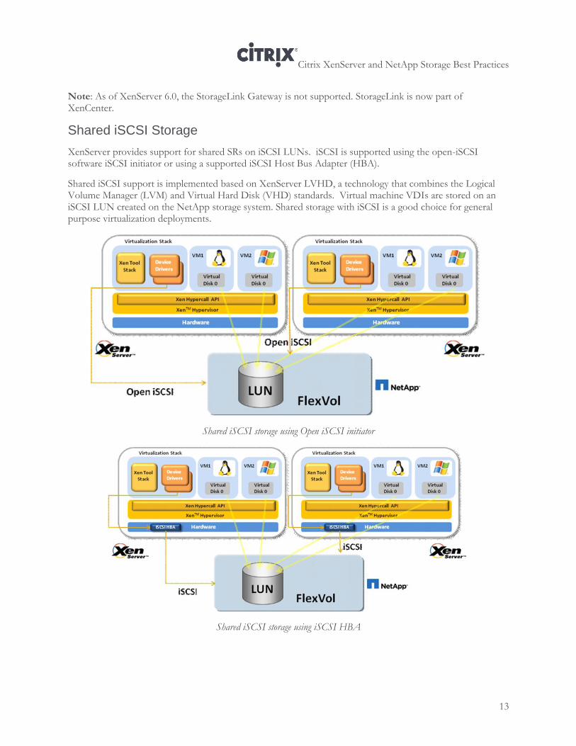
Shared iSCSI Storage
XenServer provides support for shared SRs on iSCSI LUNs. iSCSI is supported using the open-iSCSI software iSCSI initiator or using a supported iSCSI Host Bus Adapter (HBA).
Shared iSCSI support is implemented based on XenServer LVHD, a technology that combines the Logical Volume Manager (LVM) and Virtual Hard Disk (VHD) standards. Virtual machine VDIs are stored on an iSCSI LUN created on the NetApp storage system. Shared storage with iSCSI is a good choice for general purpose virtualization deployments.
Shared iSCSI storage using Open iSCSI initiator
Shared iSCSI storage using iSCSI HBA
Citrix XenServer and NetApp Storage Best Practices
14
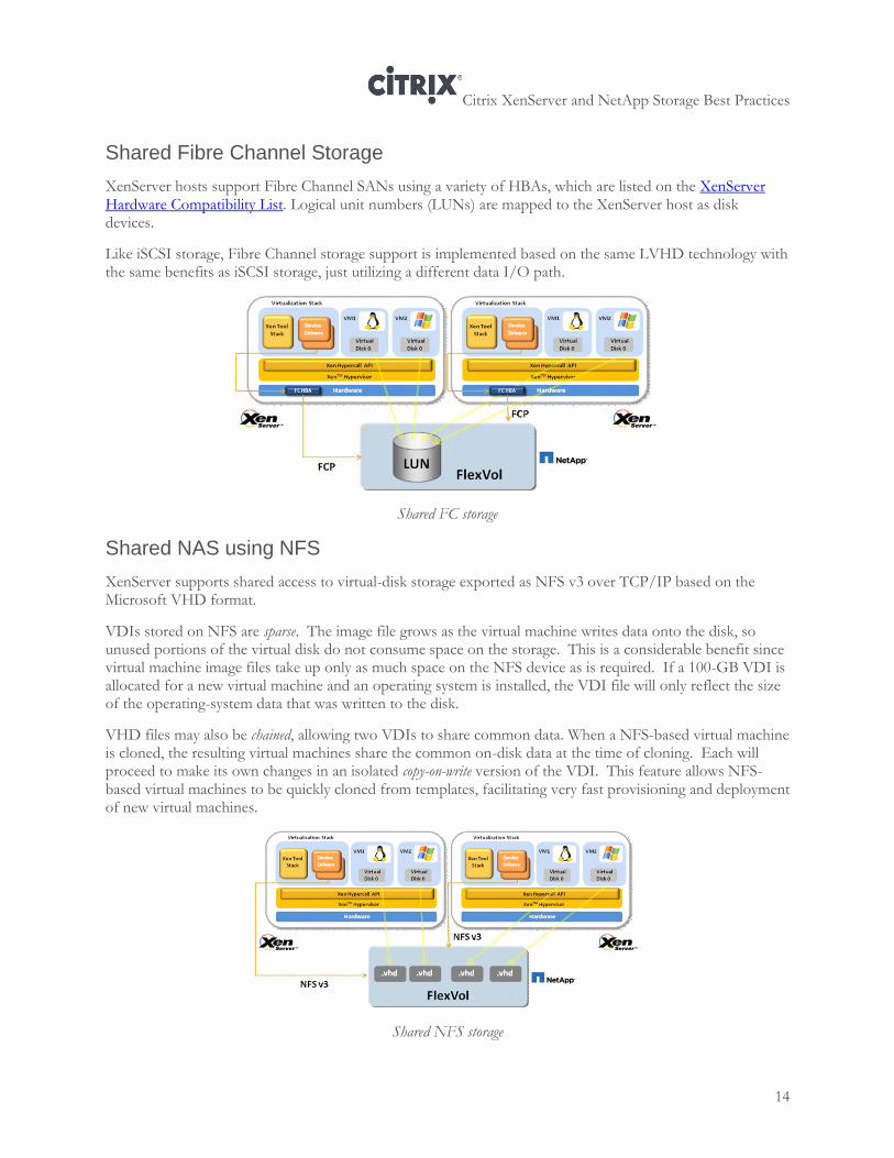
Shared Fibre Channel Storage
XenServer hosts support Fibre Channel SANs using a variety of HBAs, which are listed on the XenServer Hardware Compatibility List. Logical unit numbers (LUNs) are mapped to the XenServer host as disk devices.
Like iSCSI storage, Fibre Channel storage support is implemented based on the same LVHD technology with the same benefits as iSCSI storage, just utilizing a different data I/O path.
Shared FC storage
Shared NAS using NFS
XenServer supports shared access to virtual-disk storage exported as NFS v3 over TCP/IP based on the Microsoft VHD format.
VDIs stored on NFS are sparse. The image file grows as the virtual machine writes data onto the disk, so unused portions of the virtual disk do not consume space on the storage. This is a considerable benefit since virtual machine image files take up only as much space on the NFS device as is required. If a 100-GB VDI is allocated for a new virtual machine and an operating system is installed, the VDI file will only reflect the size of the operating-system data that was written to the disk.
VHD files may also be chained, allowing two VDIs to share common data. When a NFS-based virtual machine is cloned, the resulting virtual machines share the common on-disk data at the time of cloning. Each will proceed to make its own changes in an isolated copy-on-write version of the VDI. This feature allows NFS-based virtual machines to be quickly cloned from templates, facilitating very fast provisioning and deployment of new virtual machines.
Shared NFS storage
Citrix XenServer and NetApp Storage Best Practices
15
Chapter 3: NetApp Configuration and Setup
This chapter covers the best practices for configuring the NetApp active-active controller configuration, including how to configure:
Interface groups (also known as VIFs) and aggregates
Thin Provisioning
Space reservations with fractional reservations
Space reclaiming with NetApp deduplication
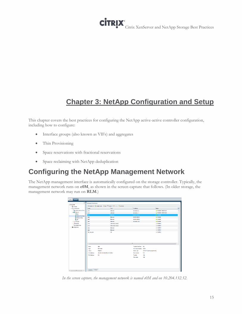
Configuring the NetApp Management Network
The NetApp management interface is automatically configured on the storage controller. Typically, the management network runs on e0M, as shown in the screen capture that follows. (In older storage, the management network may run on RLM.)
In the screen capture, the management network is named e0M and on 10.204.132.52.
Citrix XenServer and NetApp Storage Best Practices
16
The NetApp management interface should not be bonded (used in a VIF) or used for any non-management traffic, such as storage traffic. The management interface should be on its own subnet.
Best Practice
When using NetApp with XenServer, do not allow iSCSI traffic on the NetApp management interface. If XenServer detects iSCSI traffic on this network, it uses the network and, especially when multipathing is enabled, sends iSCSI traffic through it.
Obtaining the IP address for a NetApp Storage Controller
When specifying an IP address for the controller, specify the IP address associated with the first non-management network interface.
To obtain the IP address for a controller
1. In NetApp System Manager, in the left pane, select <your controller> > Configuration > Network > Network Interfaces.
2. In the list that appears, in the Name column, look for either e0a or vif0. In the screen capture on page 15, the IP address of the controller is 10.204.132.54.
(The storage management network runs on e0M. In older storage, the management network may run on RLM. In the screen capture on page 15, the management network is on 10.204.132.52.)
Configuring a NetApp VIF
A NetApp VIF, sometimes known as an interface group, is a way of aggregating up to four network interfaces on the storage system into one logical interface unit. NetApp VIFs provide failover for the network connection and, in some cases, increased throughput to the storage device. In many ways, a NetApp VIF is similar to NIC teaming or NIC bonding.
Best Practice
NetApp recommends that storage controllers have two or more target ports to create redundant paths between the NetApp storage and XenServer. For the best performance, configure the maximum amount of network connections for both controllers for optimal performance.
When multiple virtual interfaces are grouped together, NetApp refers to the link they collectively form as a trunk.
While NetApp provides three types of VIFs (static, single mode, and dynamic mode), the best practice is to use dynamic mode. Dynamic mode VIFs use Link Aggregation Control Protocol (LACP). These VIFs can detect if a link is lost and if the storage controller cannot communicate with the directly attached switch port.
Citrix XenServer and NetApp Storage Best Practices
17
Best Practice
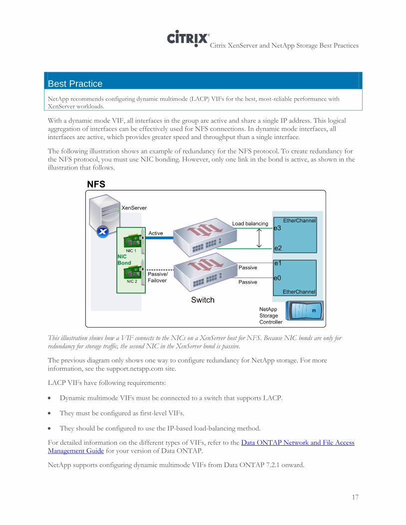
NetApp recommends configuring dynamic multimode (LACP) VIFs for the best, most-reliable performance with XenServer workloads.
With a dynamic mode VIF, all interfaces in the group are active and share a single IP address. This logical aggregation of interfaces can be effectively used for NFS connections. In dynamic mode interfaces, all interfaces are active, which provides greater speed and throughput than a single interface.
The following illustration shows an example of redundancy for the NFS protocol. To create redundancy for the NFS protocol, you must use NIC bonding. However, only one link in the bond is active, as shown in the illustration that follows.
This illustration shows how a VIF connects to the NICs on a XenServer host for NFS. Because NIC bonds are only for redundancy for storage traffic, the second NIC in the XenServer bond is passive.
The previous diagram only shows one way to configure redundancy for NetApp storage. For more information, see the support.netapp.com site.
LACP VIFs have following requirements:
Dynamic multimode VIFs must be connected to a switch that supports LACP.
They must be configured as first-level VIFs.
They should be configured to use the IP-based load-balancing method.
For detailed information on the different types of VIFs, refer to the Data ONTAP Network and File Access Management Guide for your version of Data ONTAP.
NetApp supports configuring dynamic multimode VIFs from Data ONTAP 7.2.1 onward.
Citrix XenServer and NetApp Storage Best Practices
18
Requirements
The following prerequisites must be met before creating a VIF:
Configure the VIF as a first-level VIF.
All dynamic mode VIFs must be:
Active and share a same MAC address.
Be located on a non-routable VLAN or network created for NFS network traffic
Configured into a trunk, either manually as a multimode VIF or dynamically as a LACP VIF
If LACP is used, set the VIF type to static LACP instead of multimode on the NetApp storage controller
Set the storage controller and switch ports that are part of the dynamic mode VIF to the same speed, duplex, and flow control settings.
For more information about NetApp VIFs, see the network management guide for your version of ONTAP (for example, Data ONTAP 8.1 7-Mode Network Management Guide).
Before You Begin
Identify or install a switch that supports link aggregation over multiple port connections in your network, configured according to your switch vendor's instructions. Configure the switch so all port connections form one logical port. (The switch must support manually configurable trunking over multiple port connections.)
Note: If you have already connected this controller to XenServer by creating an SR, be sure to detach the SR in XenCenter before performing this procedure.
For more information about creating a VIF, see the network management guide for your version of ONTAP (for example, Data ONTAP 8.1 7-Mode Network Management Guide).
To create a dynamic multimode (LACP) VIF
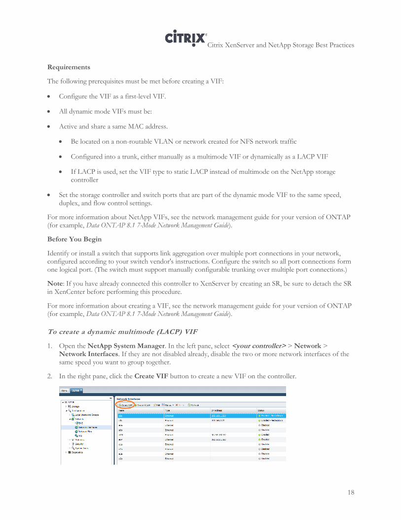
1. Open the NetApp System Manager. In the left pane, select <your controller> > Network > Network Interfaces. If they are not disabled already, disable the two or more network interfaces of the same speed you want to group together.
2. In the right pane, click the Create VIF button to create a new VIF on the controller.
Citrix XenServer and NetApp Storage Best Practices
19
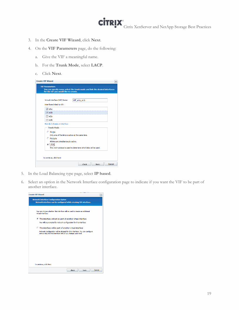
3. In the Create VIF Wizard, click Next.
4. On the VIF Parameters page, do the following:
a. Give the VIF a meaningful name.
b. For the Trunk Mode, select LACP.
c. Click Next.
5. In the Load Balancing type page, select IP based.
6. Select an option in the Network Interface configuration page to indicate if you want the VIF to be part of another interface.
Citrix XenServer and NetApp Storage Best Practices
20
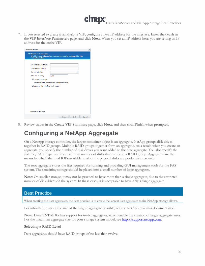
7. If you selected to create a stand-alone VIF, configure a new IP address for the interface. Enter the details in the VIF Interface Parameters page, and click Next. When you set an IP address here, you are setting an IP address for the entire VIF.
8. Review values in the Create VIF Summary page, click Next, and then click Finish when prompted.
Configuring a NetApp Aggregate
On a NetApp storage controller, the largest container object is an aggregate. NetApp groups disk drives together in RAID groups. Multiple RAID groups together form an aggregate. As a result, when you create an aggregate, you specify the number of disk drives you want added to the new aggregate. You also specify the volume, RAID type, and the maximum number of disks that can be in a RAID group. Aggregates are the means by which the total IOPs available to all of the physical disks are pooled as a resource.
The root aggregate stores the files required for running and providing GUI management tools for the FAS system. The remaining storage should be placed into a small number of large aggregates.
Note: On smaller storage, it may not be practical to have more than a single aggregate, due to the restricted number of disk drives on the system. In these cases, it is acceptable to have only a single aggregate.
Best Practice
When creating the data aggregate, the best practice is to create the largest data aggregate as the NetApp storage allows.
For information about the size of the largest aggregate possible, see the NetApp maximas documentation.
Note: Data ONTAP 8.x has support for 64-bit aggregates, which enable the creation of larger aggregate sizes. For the maximum aggregate size for your storage system model, see http://support.netapp.com.
Selecting a RAID Level
Data aggregates should have RAID groups of no less than twelve.
Citrix XenServer and NetApp Storage Best Practices
21
Best Practice
To achieve safety and economy, NetApp recommends configuring NetApp recommends using RAID-DP on all RAID groups that store XenServer data.
Using NetApp RAID-DP
NetApp RAID-DP is an advanced RAID 6 technology. While all RAID 6 implementations protect against double disk failures and MEDR, most come with a substantial performance penalty that disqualifies them from production storage environments. NetApp RAID-DP mitigates the risks of RAID 5, the budget impact of RAID 1+0, and the performance issues of other RAID 6 implementations. NetApp RAID-DP is the only RAID 6 solution offering double-parity protection without compromise to budgets, performance, or data protection. NetApp RAID-DP delivers maximum double-disk failure protection, substantially lower performance overhead than competitive RAID 6 implementations, and a cost equal to or less than single-parity RAID 5.
To create an aggregate using NetApp System Manager
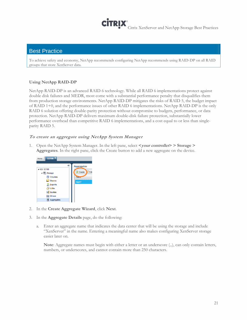
1. Open the NetApp System Manager. In the left pane, select <your controller> > Storage > Aggregates. In the right pane, click the Create button to add a new aggregate on the device.
2. In the Create Aggregate Wizard, click Next.
3. In the Aggregate Details page, do the following:
a. Enter an aggregate name that indicates the data center that will be using the storage and include “XenServer” in the name. Entering a meaningful name also makes configuring XenServer storage easier later on.
Note: Aggregate names must begin with either a letter or an underscore (_), can only contain letters, numbers, or underscores, and cannot contain more than 250 characters.
Citrix XenServer and NetApp Storage Best Practices
22
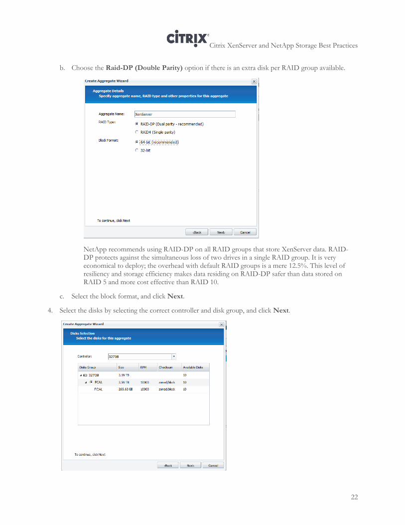
b. Choose the Raid-DP (Double Parity) option if there is an extra disk per RAID group available.
NetApp recommends using RAID-DP on all RAID groups that store XenServer data. RAID-DP protects against the simultaneous loss of two drives in a single RAID group. It is very economical to deploy; the overhead with default RAID groups is a mere 12.5%. This level of resiliency and storage efficiency makes data residing on RAID-DP safer than data stored on RAID 5 and more cost effective than RAID 10.
c. Select the block format, and click Next.
4. Select the disks by selecting the correct controller and disk group, and click Next.
Citrix XenServer and NetApp Storage Best Practices
23
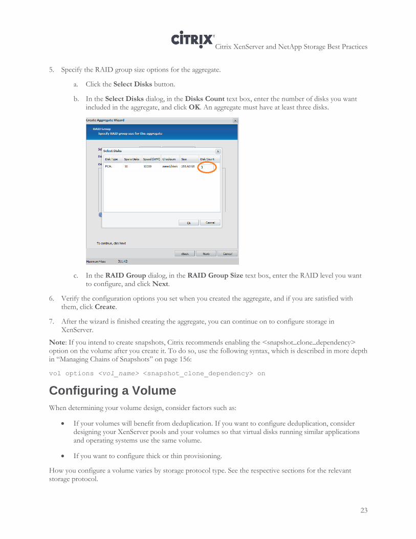
5. Specify the RAID group size options for the aggregate.
a. Click the Select Disks button.
b. In the Select Disks dialog, in the Disks Count text box, enter the number of disks you want included in the aggregate, and click OK. An aggregate must have at least three disks.
c. In the RAID Group dialog, in the RAID Group Size text box, enter the RAID level you want to configure, and click Next.
6. Verify the configuration options you set when you created the aggregate, and if you are satisfied with them, click Create.
7. After the wizard is finished creating the aggregate, you can continue on to configure storage in XenServer.
Note: If you intend to create snapshots, Citrix recommends enabling the <snapshot_clone_dependency> option on the volume after you create it. To do so, use the following syntax, which is described in more depth in “Managing Chains of Snapshots” on page 156:
vol options <vol_name> <snapshot_clone_dependency> on
Configuring a Volume
When determining your volume design, consider factors such as:
If your volumes will benefit from deduplication. If you want to configure deduplication, consider designing your XenServer pools and your volumes so that virtual disks running similar applications and operating systems use the same volume.
If you want to configure thick or thin provisioning.
How you configure a volume varies by storage protocol type. See the respective sections for the relevant storage protocol.
Citrix XenServer and NetApp Storage Best Practices
24
Choosing Thin Provisioning or Thick Provisioning
NetApp and XenServer both support provisioning storage as either thick or thin.
Thick provisioning pre-allocates storage; thin provisioning provides storage on demand.
Thin provisioning lets the administrator make more efficient use of storage space in order to avoid
running out of storage and reduces the associated application downtime when expanding the provisioned
storage.
Although no system can be run at 100% storage utilization, there are methods of storage virtualization that let administrators oversubscribe storage in the same manner as server resources (such as CPU, memory, networking, and so on).
The value of thin-provisioned storage is that storage is treated as a shared resource and is consumed only when each individual virtual machine requires it. This sharing increases the total utilization rate of storage by eliminating the unused but provisioned areas of storage that are associated with traditional storage.
The drawback to thin provisioning and oversubscribing storage is that (without the addition of physical storage) if every virtual machine requires its maximum possible storage at the same time, there will not be enough storage to satisfy the requests. As a result, more storage space may appear available to the virtual machines than is actually available on the associated SR.
It is important to note that there are no space guarantees, and allocation of a LUN does not claim any data blocks in the FlexVol until the virtual machine writes data into it.
Thin provisioning is a very useful space conserving mechanism for virtual-machine disk storage, since many virtual machines are likely to significantly under-utilize all the virtual disk space allocated.
Because space is not guaranteed when operating in thin-provisioning mode, it is possible to over-provision the amount of allocated space. If an over-provisioned aggregate runs out of space, a LUN will be forcibly set offline when any data writes are received, which may cause a virtual machine to crash. Using the NetApp Data ONTAP alerts can greatly improve the management of space usage.
Recommended Storage-Management Policies for Thin Provisioning
NetApp recommends that when you enable NetApp thin provisioning, you also configure storage-management policies on the volumes that contain the thin-provisioned LUNs. These policies help provide the thin-provisioned LUNs with storage capacity, as they require it. The policies include automatic sizing of a volume and automatic Snapshot deletion.
Volume Auto Size
Volume Auto Size is a policy-based space management feature in Data ONTAP that lets a volume grow in defined increments up to a predefined limit when the volume is nearly full. For Citrix environments, NetApp recommends setting this value to ‘on’. Doing so requires setting the maximum volume and increment size options. 1. Log in to NetApp console. 2. Set Volume Auto Size Policy
Vol autosize <vol-name> [-m <size>[k|m|g|t]][-i <size>[k|m|g|t]] on.
Citrix XenServer and NetApp Storage Best Practices
25
Snapshot Auto Delete
Snapshot Auto Delete is a policy-based space-management feature that automatically deletes the oldest
Snapshot copies on a volume when that volume is nearly full. NetApp recommends setting this value to delete Snapshot copies at 5% of available space. In addition, you should set the volume option to have the system attempt to grow the volume before deleting Snapshot copies. 1. Log in to NetApp console. 2. Set Snapshot Auto Delete Policy 3. snap autodelete <vol-name> commitment try trigger
snap autodelete <vol-name> commitment try triggervolume
target_free_space 5 delete_order oldest_first.
Reclaiming Space with NetApp Deduplication
In some virtualized environments, NetApp deduplication helps saves space by reducing duplicated stored data, such as guest operating systems or applications, and reclaiming redundant copies of blocks in a volume. Whether or not deduplication is valuable varies according to the way in which the SR was created and your goals.
Deduplication is enabled at the volume level. It can be enabled on any number of flexible volumes in a storage system. It can be run one of four different ways:
Scheduled on specific days and at specific times
Manually, by using the command line
Automatically, when 20% new data has been written to the volume
Automatically on the destination volume, when used with SnapVault
Below are some results from testing NetApp deduplication:
Supported by all storage data access types; iSCSI, FCP & NFS
>70% with virtualization environment
In some cases, but not always in virtualized environments, saves up to 95% for full backups; 25% to 55% for most data sets.
Use with Standard (Non-StorageLink) SRs
If your SRs are using NFS or iSCSI or Fibre Channel (LVHD) connectivity, deduplication is helpful since multiple virtual disks reside in the same volume. Deduplication is particularly useful with NFS since, typically, an NFS store has more virtual disks than an individual iSCSI or Fibre Channel SR.
The amount of disk space saved when deduplication is running varies according to how you schedule it to run. While deduplication runs in the background, it consumes compute cycles on the storage. As a result, you may want to schedule deduplication to avoid peak periods of activity, such as the morning boot and login cycles. However, when you delay deduplication, more disk space is used until the process can be run.
NetApp deduplication is post process and should be scheduled when storage demands are light to avoid adding additional load during peak production times.
Citrix XenServer and NetApp Storage Best Practices
26
Use with StorageLink SRs
The value of using deduplication typically varies according to the way in which you created the StorageLink SRs. As described in more depth on page 75, there are two methods of configuring StorageLink:
Precreated volumes. When you specify a previously created volume when using the StorageLink SR wizard to create an SR, for each virtual disk, a LUN is created in the volume. In this case, deduplication is useful because there is a considerable amount of data in a volume that might be duplicated.
StorageLink-created volumes. When each virtual disk has its own volume, deduplication is not as helpful unless there is redundant data in the volume, such as an unencrypted backup repository.
Note: If NetApp deduplication is going to be enabled for the FlexVol® from XenCenter or StorageLink, note that the volume size should match the maximum supported deduplication limit for the device.
Considerations
The maximum flexible volume size limitation for deduplication varies based on the platform (this number depends primarily on the amount of system memory). When this limit is reached, writes to the volume fail just as they would with any other volume after it is full.
This could be important to consider if the flexible volumes are ever moved to a different platform with a smaller maximum flexible volume size. For current volume limits, please consult TR-3505: NetApp Deduplication for FAS and V-Series Deployment and Implementation Guide, available at http://support.netapp.com/.
The maximum shared data limit per volume for deduplication is 16TB, regardless of the platform type. Once this limit is reached, there is no more deduplication of data in the volume, but writes to the volume continue to work successfully until the volume is completely full.
When data deduplication is enabled on a volume, the amount of data deduplication realized is based on the similarity of the data stored in the volume. For the largest storage savings, NetApp recommends grouping similar operating systems and similar applications into one volume. For deduplication best practices, including scheduling and performance considerations, see TR 3505 NetApp FAS Dedupe: Data Deduplication Deployment and Implementation Guide.
Notes:
Only one deduplication process can run on a flexible volume at a time.
Up to eight deduplication processes can run concurrently on eight volumes within the same NetApp active-active controller configuration.
If deduplication is paused or interrupted for whatever reason, you do not have to start deduplication again. Deduplication checkpoint restart allows a deduplication process that was interrupted to continue from the last checkpoint. If the system is restarted while deduplication is in process, when the system is once again online, the deduplication process automatically restarts from the last checkpoint.
Citrix XenServer and NetApp Storage Best Practices
27
Creating a Volume
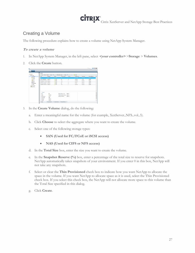
The following procedure explains how to create a volume using NetApp System Manager.
To create a volume
1. In NetApp System Manager, in the left pane, select <your controller> >Storage > Volumes.
2. Click the Create button.
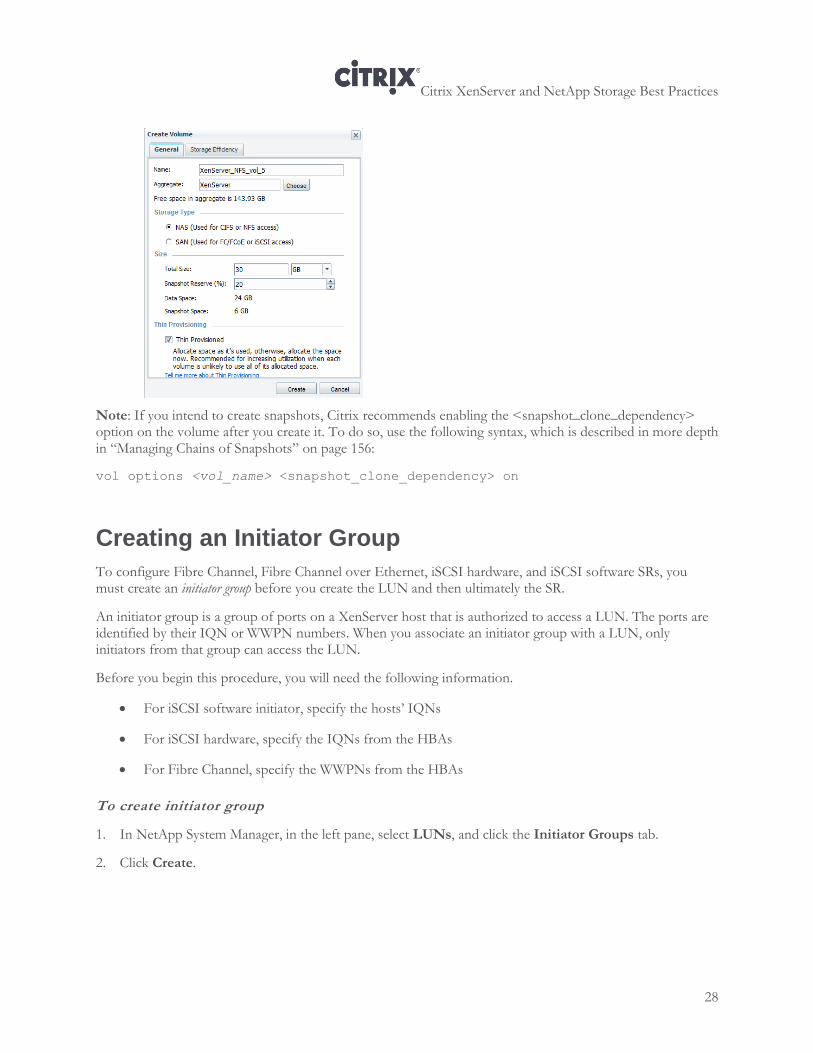
3. In the Create Volume dialog, do the following:
a. Enter a meaningful name for the volume (for example, XenServer_NFS_vol_5).
b. Click Choose to select the aggregate where you want to create the volume.
c. Select one of the following storage types:
SAN (Used for FC/FCoE or iSCSI access)
NAS (Used for CIFS or NFS access)
d. In the Total Size box, enter the size you want to create the volume.
e. In the Snapshot Reserve (%) box, enter a percentage of the total size to reserve for snapshots. NetApp automatically takes snapshots of your environment. If you enter 0 in this box, NetApp will not take any snapshots.
f. Select or clear the Thin Provisioned check box to indicate how you want NetApp to allocate the space in the volume. If you want NetApp to allocate space as it is used, select the Thin Provisioned check box. If you select this check box, the NetApp will not allocate more space to this volume than the Total Size specified in this dialog.
g. Click Create.
Citrix XenServer and NetApp Storage Best Practices
28
Note: If you intend to create snapshots, Citrix recommends enabling the <snapshot_clone_dependency> option on the volume after you create it. To do so, use the following syntax, which is described in more depth in “Managing Chains of Snapshots” on page 156:
vol options <vol_name> <snapshot_clone_dependency> on
Creating an Initiator Group
To configure Fibre Channel, Fibre Channel over Ethernet, iSCSI hardware, and iSCSI software SRs, you must create an initiator group before you create the LUN and then ultimately the SR.
An initiator group is a group of ports on a XenServer host that is authorized to access a LUN. The ports are identified by their IQN or WWPN numbers. When you associate an initiator group with a LUN, only initiators from that group can access the LUN.
Before you begin this procedure, you will need the following information.
For iSCSI software initiator, specify the hosts’ IQNs
For iSCSI hardware, specify the IQNs from the HBAs
For Fibre Channel, specify the WWPNs from the HBAs
To create initiator group
1. In NetApp System Manager, in the left pane, select LUNs, and click the Initiator Groups tab.
2. Click Create.
Citrix XenServer and NetApp Storage Best Practices
29
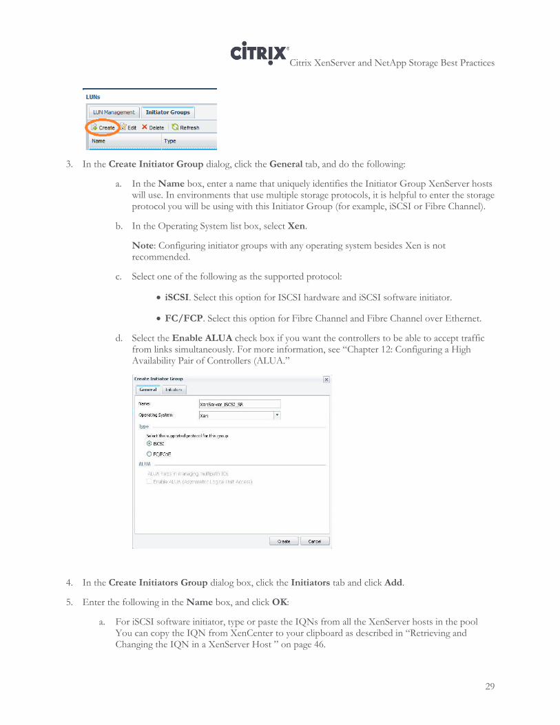
3. In the Create Initiator Group dialog, click the General tab, and do the following:
a. In the Name box, enter a name that uniquely identifies the Initiator Group XenServer hosts will use. In environments that use multiple storage protocols, it is helpful to enter the storage protocol you will be using with this Initiator Group (for example, iSCSI or Fibre Channel).
b. In the Operating System list box, select Xen.
Note: Configuring initiator groups with any operating system besides Xen is not recommended.
c. Select one of the following as the supported protocol:
iSCSI. Select this option for ISCSI hardware and iSCSI software initiator.
FC/FCP. Select this option for Fibre Channel and Fibre Channel over Ethernet.
d. Select the Enable ALUA check box if you want the controllers to be able to accept traffic from links simultaneously. For more information, see “Chapter 12: Configuring a High Availability Pair of Controllers (ALUA.”
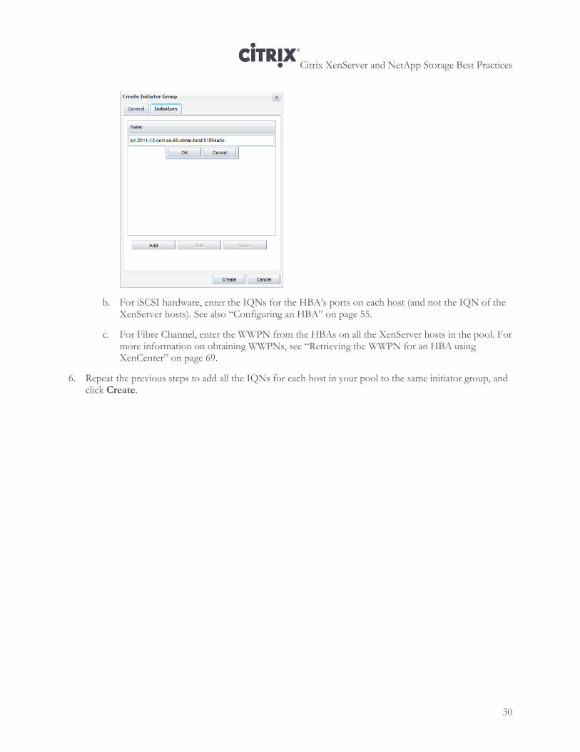
4. In the Create Initiators Group dialog box, click the Initiators tab and click Add.
5. Enter the following in the Name box, and click OK:
a. For iSCSI software initiator, type or paste the IQNs from all the XenServer hosts in the pool You can copy the IQN from XenCenter to your clipboard as described in “Retrieving and Changing the IQN in a XenServer Host ” on page 46.
Citrix XenServer and NetApp Storage Best Practices
30
b. For iSCSI hardware, enter the IQNs for the HBA’s ports on each host (and not the IQN of the XenServer hosts). See also “Configuring an HBA” on page 55.
c. For Fibre Channel, enter the WWPN from the HBAs on all the XenServer hosts in the pool. For more information on obtaining WWPNs, see “Retrieving the WWPN for an HBA using XenCenter” on page 69.
6. Repeat the previous steps to add all the IQNs for each host in your pool to the same initiator group, and click Create.
Citrix XenServer and NetApp Storage Best Practices
31
Chapter 4: XenServer Storage Best Practices
This chapter covers the best practices for configuring the various available storage options (NFS, iSCSI, FC) with a NetApp active-active configuration, including:
Best practices for XenServer IP-based storage networks
Best practices for creating redundancy for storage traffic
Overview
This chapter provides an introduction to best practices for networking and creating redundancy for XenServer IP-based storage, such as NFS and iSCSI software initiator.
In general, Citrix recommends separating storage traffic from other traffic types by creating a dedicated network for storage traffic and ensuring the traffic is actually segregated, as described in the section that follows.
XenServer supports two types of redundancy for storage networks: multipathing and bonding. Configuring multipathing or bonding helps provide redundancy for network storage traffic in case of partial network or device failure. The term multipathing refers to routing storage traffic to a storage device over multiple paths for redundancy (failover) and increased throughput. The term bonding, often known as NIC teaming, connects two NICs together as a logical channel.
In general, Citrix recommends multipathing over NIC bonding. However, this may not be possible for all storage protocols, such as NFS. This topic is discussed in more detail in “Selecting XenServer Multipathing or NIC Bonding.”
Best Practices for IP-Based Storage Networks
If you want to configure NFS or iSCSI software initiator storage, it is worth reviewing the following section, which provides best-practice information about XenServer networking for IP-based storage.
In most XenServer environments, the best practice is to segregate traffic according to traffic type: XenServer management traffic, VM traffic, and storage traffic. Specifically, for NFS and iSCSI storage implementations, Citrix recommends dedicating one or more NICs as a separate storage network. In smaller environments, routing guest, management, and/or storage traffic together may not matter. However, in larger environments
Citrix XenServer and NetApp Storage Best Practices
32
or environments with strict security policies, you may want to separate your traffic.
Best Practice
Citrix recommends segregating management, storage, and VM traffic so that each traffic type is on its own network. This reduces contention, simplifies security, and improves manageability.
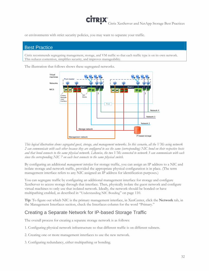
The illustration that follows shows these segregated networks.
This logical illustration shows segregated guest, storage, and management networks. In this scenario, all the VMs using network 2 can communicate with each other because they are configured to use the same (corresponding) NIC bond on their respective hosts and that bond connects to the same physical network. Likewise, the two VMs connected to network 3 can communicate with each since the corresponding NIC 7 on each host connects to the same physical switch.
By configuring an additional management interface for storage traffic, you can assign an IP address to a NIC and isolate storage and network traffic, provided the appropriate physical configuration is in place. (The term management interface refers to any NIC assigned an IP address for identification purposes.)
You can segregate traffic by configuring an additional management interface for storage and configure XenServer to access storage through that interface. Then, physically isolate the guest network and configure virtual machines to only use that isolated network. Ideally, the network should be bonded or have multipathing enabled, as described in “Understanding NIC Bonding” on page 110.
Tip: To figure out which NIC is the primary management interface, in XenCenter, click the Network tab, in the Management Interfaces section, check the Interfaces column for the word “Primary.”
Creating a Separate Network for IP-based Storage Traffic
The overall process for creating a separate storage network is as follows:
1. Configuring physical network infrastructure so that different traffic is on different subnets.
2. Creating one or more management interfaces to use the new network.
3. Configuring redundancy, either multipathing or bonding.
Citrix XenServer and NetApp Storage Best Practices
33
For IP-based storage, such as iSCSI software initiator and NFS, to communicate with XenServer, the XenServer NICs must have IP addresses. To specify an IP address for a NIC or bond, requires either:
Configuring additional (non-primary) management interfaces so you can assign IP addresses to NICs
besides the primary management interface for routing storage traffic.
Routing storage traffic through the primary management interface—since the primary management
interface has an IP address this will work.
The best practice recommendation is to create an additional management interface and segregating the storage traffic on its own network. If desired, you can bond the storage network.
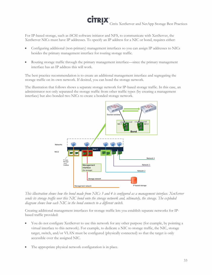
The illustration that follows shows a separate storage network for IP-based storage traffic. In this case, an administrator not only separated the storage traffic from other traffic types (by creating a management interface) but also bonded two NICs to create a bonded storage network.
This illustration shows how the bond made from NICs 3 and 4 is configured as a management interface. XenServer sends its storage traffic over this NIC bond onto the storage network and, ultimately, the storage. The exploded diagram shows how each NIC in the bond connects to a different switch.
Creating additional management interfaces for storage traffic lets you establish separate networks for IP-based traffic provided:
You do not configure XenServer to use this network for any other purpose (for example, by pointing a
virtual interface to this network). For example, to dedicate a NIC to storage traffic, the NIC, storage
target, switch, and/or VLAN must be configured (physically connected) so that the target is only
accessible over the assigned NIC.
The appropriate physical network configuration is in place.
Citrix XenServer and NetApp Storage Best Practices
34
To ensure that the storage traffic is separated from the management traffic, the storage network must be on a different subnet network than the primary management interface. The subnet for storage must be a separate IP subnet that is not “routable” from the primary management interface. If the physical or logical configuration does not enforce the traffic separation, XenServer may direct storage traffic over the primary management interface after a host reboot, due to the order in which XenServer initializes NICs.
Some environments, such as test labs or at very small companies, may experience little impact from routing management and storage traffic on one interface. However, in general, Citrix strongly recommends that you do not route storage traffic over the primary management interface.
If you want to bond a management interface, create the management interface first and then bond it.
Depending on your redundancy requirements, you can connect the NICs in the bond to either the same or separate switches. (If you connect one of the NICs to a second, redundant switch and a NIC or switch fails, traffic fails over to the other NIC.)
If you choose to connect the NICs to two separate switches, the switches must be on the same physical network and be functioning as one logical switch, as described in “Understanding NIC Bonding” on page 110.
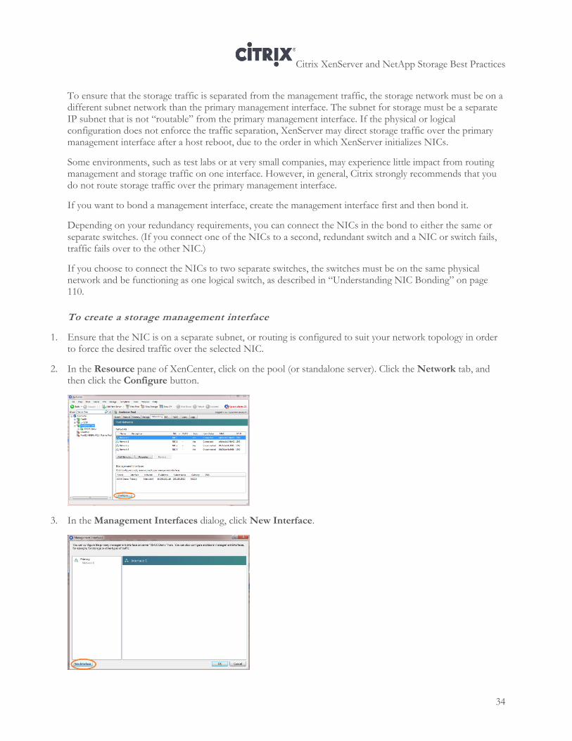
To create a storage management interface
1. Ensure that the NIC is on a separate subnet, or routing is configured to suit your network topology in order to force the desired traffic over the selected NIC.
2. In the Resource pane of XenCenter, click on the pool (or standalone server). Click the Network tab, and then click the Configure button.
3. In the Management Interfaces dialog, click New Interface.
Citrix XenServer and NetApp Storage Best Practices
35
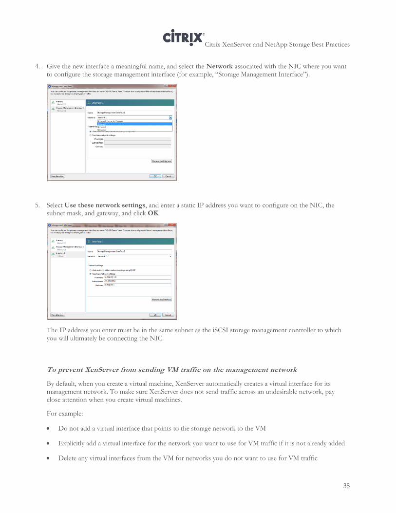
4. Give the new interface a meaningful name, and select the Network associated with the NIC where you want to configure the storage management interface (for example, “Storage Management Interface”).
5. Select Use these network settings, and enter a static IP address you want to configure on the NIC, the subnet mask, and gateway, and click OK.
The IP address you enter must be in the same subnet as the iSCSI storage management controller to which you will ultimately be connecting the NIC.
To prevent XenServer from sending VM traffic on the management network
By default, when you create a virtual machine, XenServer automatically creates a virtual interface for its management network. To make sure XenServer does not send traffic across an undesirable network, pay close attention when you create virtual machines.
For example:
Do not add a virtual interface that points to the storage network to the VM
Explicitly add a virtual interface for the network you want to use for VM traffic if it is not already added
Delete any virtual interfaces from the VM for networks you do not want to use for VM traffic
Citrix XenServer and NetApp Storage Best Practices
36
If you want to dedicate a NIC for storage, check XenCenter to make sure that the NIC’s associated network is not configured so that it is added to the VMs by default. To do so, in the Networks tab, right-click <your-storage-network> > Properties. Click Network Settings and make sure the Automatically add this network to new virtual machines check box is not selected.
To configure VMs with only guest networks
Note: In this procedure, the networks in the screen captures are renamed for clarity. Unless you change the names of your networks in XenCenter, XenServer networks do not have names like “storage network” or “management network” by default. You can use this procedure to add or remove the networks of your choice from a VM. However, the procedure is not mandatory.
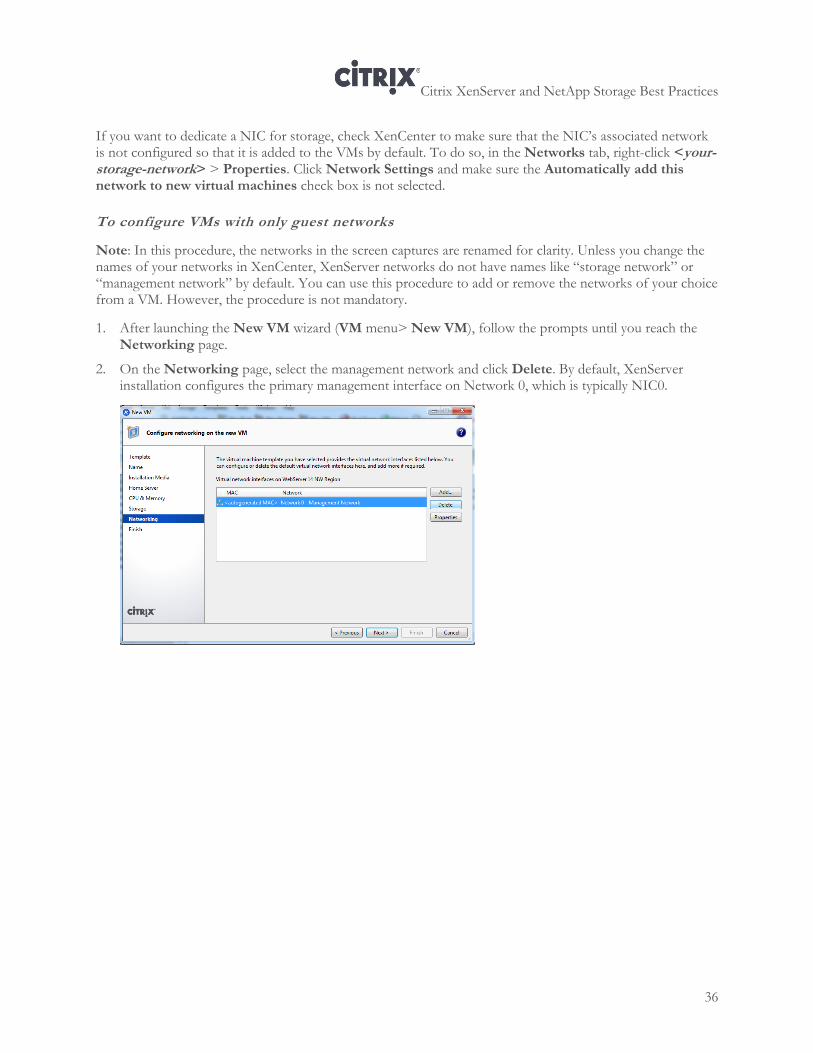
1. After launching the New VM wizard (VM menu> New VM), follow the prompts until you reach the Networking page.
2. On the Networking page, select the management network and click Delete. By default, XenServer installation configures the primary management interface on Network 0, which is typically NIC0.
Citrix XenServer and NetApp Storage Best Practices
37
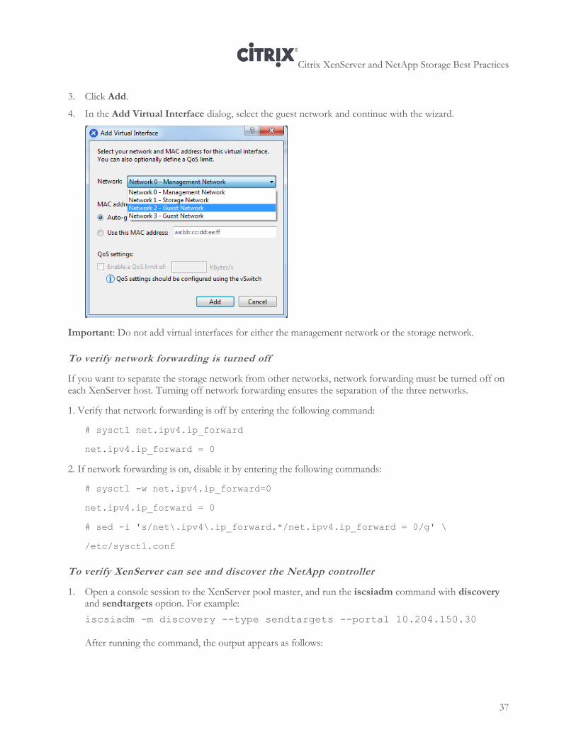
3. Click Add.
4. In the Add Virtual Interface dialog, select the guest network and continue with the wizard.
Important: Do not add virtual interfaces for either the management network or the storage network.
To verify network forwarding is turned off
If you want to separate the storage network from other networks, network forwarding must be turned off on each XenServer host. Turning off network forwarding ensures the separation of the three networks.
1. Verify that network forwarding is off by entering the following command:
# sysctl net.ipv4.ip_forward
net.ipv4.ip_forward = 0
2. If network forwarding is on, disable it by entering the following commands:
# sysctl -w net.ipv4.ip_forward=0
net.ipv4.ip_forward = 0
# sed -i 's/net\.ipv4\.ip_forward.*/net.ipv4.ip_forward = 0/g' \
/etc/sysctl.conf
To verify XenServer can see and discover the NetApp controller
1. Open a console session to the XenServer pool master, and run the iscsiadm command with discovery and sendtargets option. For example:
iscsiadm -m discovery --type sendtargets --portal 10.204.150.30
After running the command, the output appears as follows:

Citrix XenServer and NetApp Storage Best Practices
38
[root@host-34 ~]# iscsiadm -m discovery --type sendtargets --portal
10.204.150.30
10.204.150.30:3260,1000 iqn.1992-08.com.netapp:sn.1574216687
10.204.151.30:3260,1001 iqn.1992-08.com.netapp:sn.1574216687
The command returns multiple targets on the NetApp active-active controller configuration showing that the backend storage device is configured properly.
Citrix XenServer and NetApp Storage Best Practices
39
Chapter 5: XenServer NFS Storage Configuration and Setup
This chapter provides information about the following:
Enabling the NFS service on the NetApp Storage Controller
Exporting the NFS volume
Creating an NFS SR in XenCenter
Overall Process
Configure NetApp NFS storage for use with XenServer, requires the following process:
1. Using the NetApp System Manager, create the aggregate where you want to create the volume, if you
have not done so already. See “Configuring a NetApp Aggregate” page 20.
2. Using the NetApp System Manager, enable the NFS service on the NetApp, if it is not already enabled. See the section that follows.
Using the NetApp System Manager, create the NFS volume. See
Citrix XenServer and NetApp Storage Best Practices
40
3. Creating a Volume” on page 27.
4. Using the NetApp System Manager, export the NFS volume, as described in this chapter.
5. Create the SR in XenCenter.
Enabling the NFS Service on the NetApp
If it is not already enabled, start the NFS service on the storage.
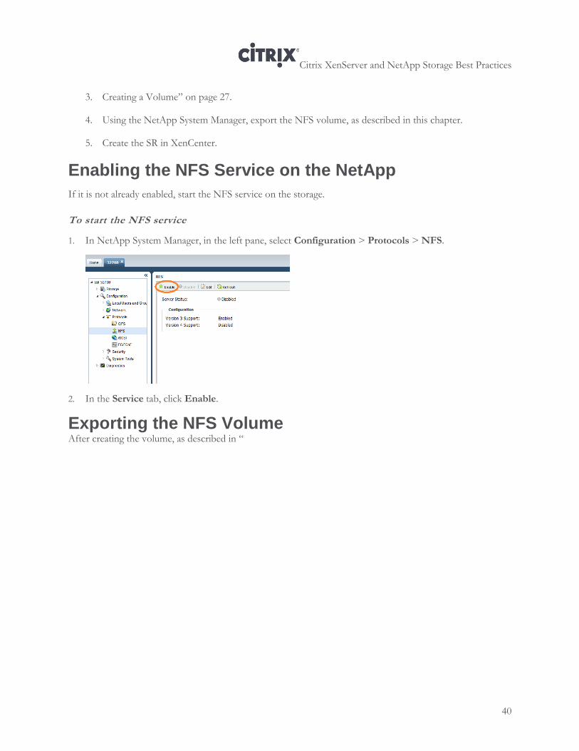
To start the NFS service
1. In NetApp System Manager, in the left pane, select Configuration > Protocols > NFS.
2. In the Service tab, click Enable.
Exporting the NFS Volume After creating the volume, as described in “
Citrix XenServer and NetApp Storage Best Practices
41
Creating a Volume” on page 27, you must export it so XenServer can connect to it.
For the XenServer host to be able to create SRs on the exported NFS target, the host’s IP address or subnet mask needs to be granted Root Access. You can grant the root access using NetApp System Manager by using one of several different approaches:
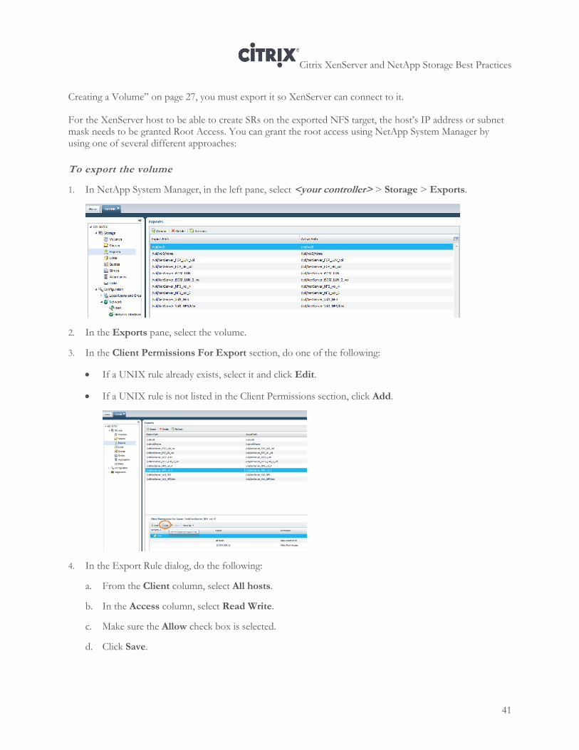
To export the volume
1. In NetApp System Manager, in the left pane, select <your controller> > Storage > Exports.
2. In the Exports pane, select the volume.
3. In the Client Permissions For Export section, do one of the following:
If a UNIX rule already exists, select it and click Edit.
If a UNIX rule is not listed in the Client Permissions section, click Add.
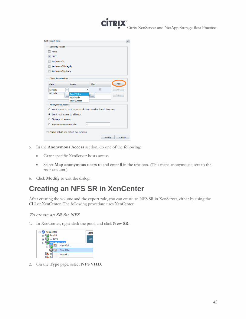
4. In the Export Rule dialog, do the following:
a. From the Client column, select All hosts.
b. In the Access column, select Read Write.
c. Make sure the Allow check box is selected.
d. Click Save.
Citrix XenServer and NetApp Storage Best Practices
42
5. In the Anonymous Access section, do one of the following:
Grant specific XenServer hosts access.
Select Map anonymous users to and enter 0 in the text box. (This maps anonymous users to the root account.)
6. Click Modify to exit the dialog.
Creating an NFS SR in XenCenter
After creating the volume and the export rule, you can create an NFS SR in XenServer, either by using the CLI or XenCenter. The following procedure uses XenCenter.
To create an SR for NFS
1. In XenCenter, right-click the pool, and click New SR.
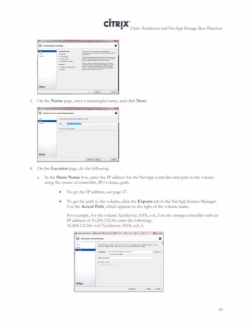
2. On the Type page, select NFS VHD.
Citrix XenServer and NetApp Storage Best Practices
43
3. On the Name page, enter a meaningful name, and click Next.
4. On the Location page, do the following:
a. In the Share Name box, enter the IP address for the NetApp controller and path to the volume using the syntax of controller_IP:/volume_path.
To get the IP address, see page 27.
To get the path to the volume, click the Exports tab in the NetApp System Manager. Use the Actual Path, which appears to the right of the volume name.
For example, for the volume XenServer_NFS_vol_5 on the storage controller with an IP address of 10.204.132.54, enter the following: 10.204.132.54:/vol/XenServer_NFS_vol_5.
Citrix XenServer and NetApp Storage Best Practices
44
b. Click Scan.
c. Leave all other settings at their default.
5. Click Finish. By default, XenServer automatically creates a VDI when you create an NFS SR. The VDI that is created in the NFS SR is thin-provisioned.
Creating an NFS Virtual Disk in the SR
The following procedure explains how to create an NFS virtual disk in the SR. Perform this procedure after creating and exporting a volume.
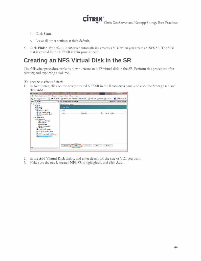
To create a virtual disk 1. In XenCenter, click on the newly created NFS SR in the Resources pane, and click the Storage tab and
click Add.
2. In the Add Virtual Disk dialog, and enter details for the size of VDI you want. 3. Make sure the newly created NFS SR is highlighted, and click Add.
Citrix XenServer and NetApp Storage Best Practices
45
Chapter 6: XenServer iSCSI Software Initiator Configuration
This chapter provides information about the following:
Configuring iSCSI software initiator storage, including how to use NetApp System Manager to create initiator groups, how to create a LUN, and how to change the IQN in XenServer and create an SR using XenServer
Configuring iSCSI software initiator storage and simultaneously creating a LUN by using StorageLink
Configuring iSCSI Software Initiator Storage
There are two paths for configuring iSCSI software initiator storage with XenServer: one that includes multipathing, listed as an optional step below, and one that does not. The overall process for configuring iSCSI software initiator storage with XenServer is as follows:
1. Using the NetApp System Manager, create the aggregate where you want the LUN to be stored, if you
have not done so already.
2. Retrieve the IQN for the XenServer host from XenCenter.
3. Using the NetApp System Manager, enable the iSCSI service on the NetApp
4. Using the NetApp System Manager, create an initiator group (also known as an igroup).
5. Using the NetApp System Manager, create the LUN.
6. (Optional.) Enable multipathing, as described in “Configuring Multipathing for iSCSI Software” on page
120.
7. Create the SR in XenCenter.
Citrix XenServer and NetApp Storage Best Practices
46
Retrieving and Changing the IQN in a XenServer Host
XenServer automatically generates a different IQN for each host that is valid for use when creating iSCSI initiator groups. However, depending on the naming conventions in your organization, you may want to change this IQN.
Even if your organization does not have naming conventions, including the host name or other meaningful information makes it easier to know what IQNs are associated with what hosts when you are creating initiator groups in NetApp System Manager.
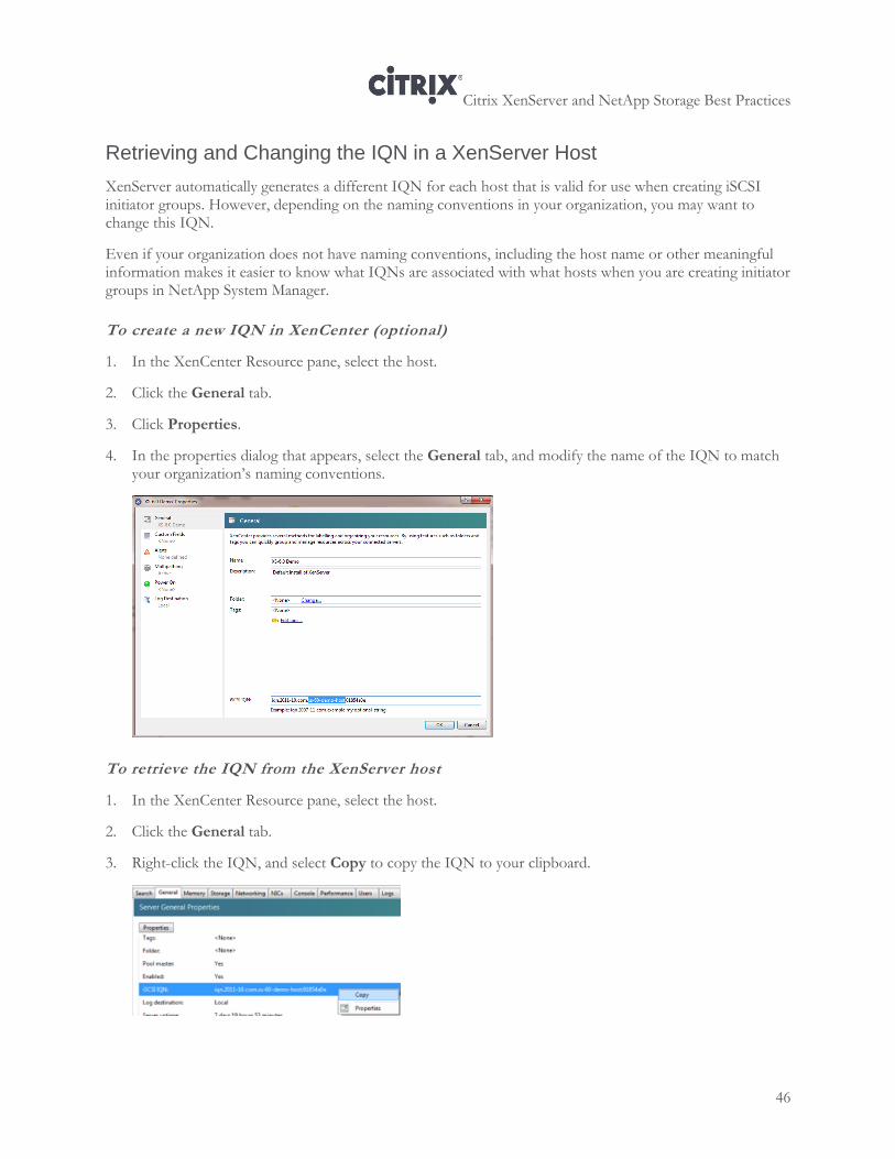
To create a new IQN in XenCenter (optional)
1. In the XenCenter Resource pane, select the host.
2. Click the General tab.
3. Click Properties.
4. In the properties dialog that appears, select the General tab, and modify the name of the IQN to match your organization’s naming conventions.
To retrieve the IQN from the XenServer host
1. In the XenCenter Resource pane, select the host.
2. Click the General tab.
3. Right-click the IQN, and select Copy to copy the IQN to your clipboard.
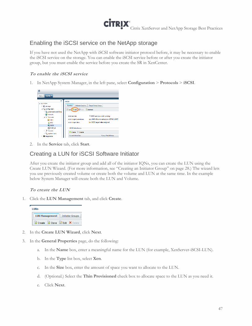
Citrix XenServer and NetApp Storage Best Practices
47
Enabling the iSCSI service on the NetApp storage
If you have not used the NetApp with iSCSI software initiator protocol before, it may be necessary to enable the iSCSI service on the storage. You can enable the iSCSI service before or after you create the initiator group, but you must enable the service before you create the SR in XenCenter.
To enable the iSCSI service
1. In NetApp System Manager, in the left pane, select Configuration > Protocols > iSCSI.
2. In the Service tab, click Start.
Creating a LUN for iSCSI Software Initiator
After you create the initiator group and add all of the initiator IQNs, you can create the LUN using the Create LUN Wizard. (For more information, see “Creating an Initiator Group” on page 28.) The wizard lets you use previously created volume or create both the volume and LUN at the same time. In the example below System Manager will create both the LUN and Volume.
To create the LUN
1. Click the LUN Management tab, and click Create.
2. In the Create LUN Wizard, click Next.
3. In the General Properties page, do the following:
a. In the Name box, enter a meaningful name for the LUN (for example, XenServer-iSCSI-LUN).
b. In the Type list box, select Xen.
c. In the Size box, enter the amount of space you want to allocate to the LUN.
d. (Optional.) Select the Thin Provisioned check box to allocate space to the LUN as you need it.
e. Click Next.
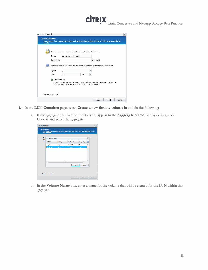
Citrix XenServer and NetApp Storage Best Practices
48
4. In the LUN Container page, select Create a new flexible volume in and do the following:
a. If the aggregate you want to use does not appear in the Aggregate Name box by default, click Choose and select the aggregate.
b. In the Volume Name box, enter a name for the volume that will be created for the LUN within that aggregate.
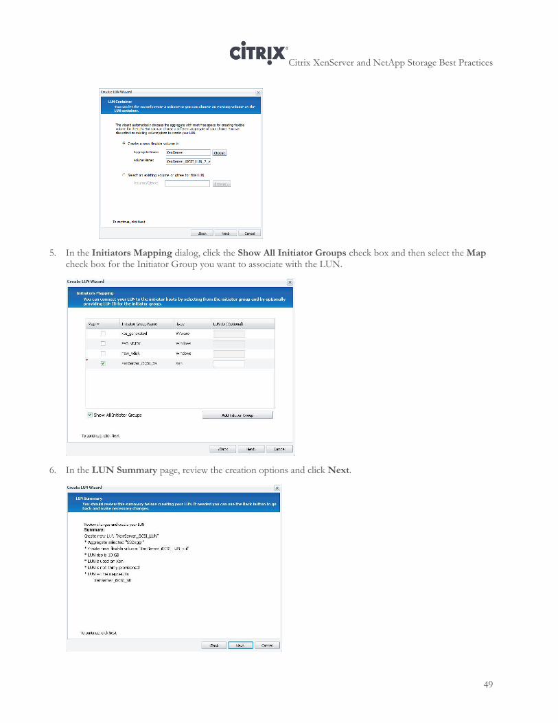
Citrix XenServer and NetApp Storage Best Practices
49
5. In the Initiators Mapping dialog, click the Show All Initiator Groups check box and then select the Map check box for the Initiator Group you want to associate with the LUN.
6. In the LUN Summary page, review the creation options and click Next.
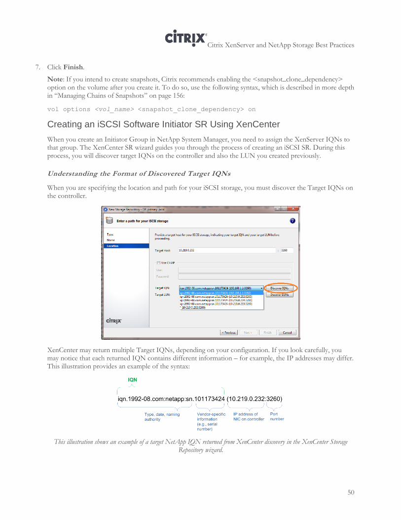
Citrix XenServer and NetApp Storage Best Practices
50
7. Click Finish.
Note: If you intend to create snapshots, Citrix recommends enabling the <snapshot_clone_dependency> option on the volume after you create it. To do so, use the following syntax, which is described in more depth in “Managing Chains of Snapshots” on page 156:
vol options <vol_name> <snapshot_clone_dependency> on
Creating an iSCSI Software Initiator SR Using XenCenter
When you create an Initiator Group in NetApp System Manager, you need to assign the XenServer IQNs to that group. The XenCenter SR wizard guides you through the process of creating an iSCSI SR. During this process, you will discover target IQNs on the controller and also the LUN you created previously.
Understanding the Format of Discovered Target IQNs
When you are specifying the location and path for your iSCSI storage, you must discover the Target IQNs on the controller.
XenCenter may return multiple Target IQNs, depending on your configuration. If you look carefully, you may notice that each returned IQN contains different information – for example, the IP addresses may differ. This illustration provides an example of the syntax:
This illustration shows an example of a target NetApp IQN returned from XenCenter discovery in the XenCenter Storage Repository wizard.
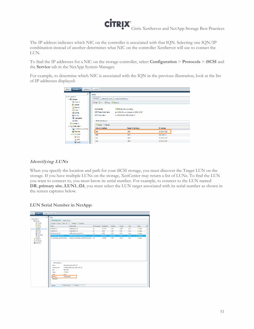
Citrix XenServer and NetApp Storage Best Practices
51
The IP address indicates which NIC on the controller is associated with that IQN. Selecting one IQN/IP combination instead of another determines what NIC on the controller XenServer will use to contact the LUN.
To find the IP addresses for a NIC on the storage controller, select Configuration > Protocols > iSCSI and the Service tab in the NetApp System Manager.
For example, to determine which NIC is associated with the IQN in the previous illustration, look at the list of IP addresses displayed:
Identifying LUNs
When you specify the location and path for your iSCSI storage, you must discover the Target LUN on the storage. If you have multiple LUNs on the storage, XenCenter may return a list of LUNs. To find the LUN you want to connect to, you must know its serial number. For example, to connect to the LUN named DR_primary site_LUN1_f24, you must select the LUN target associated with its serial number as shown in the screen captures below.
LUN Serial Number in NetApp:
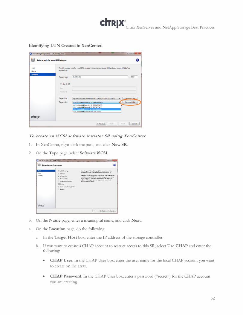
Citrix XenServer and NetApp Storage Best Practices
52
Identifying LUN Created in XenCenter:
To create an iSCSI software initiator SR using XenCenter
1. In XenCenter, right-click the pool, and click New SR.
2. On the Type page, select Software iSCSI.
3. On the Name page, enter a meaningful name, and click Next.
4. On the Location page, do the following:
a. In the Target Host box, enter the IP address of the storage controller.
b. If you want to create a CHAP account to restrict access to this SR, select Use CHAP and enter the following:
CHAP User. In the CHAP User box, enter the user name for the local CHAP account you want
to create on the array.
CHAP Password. In the CHAP User box, enter a password (“secret”) for the CHAP account
you are creating.
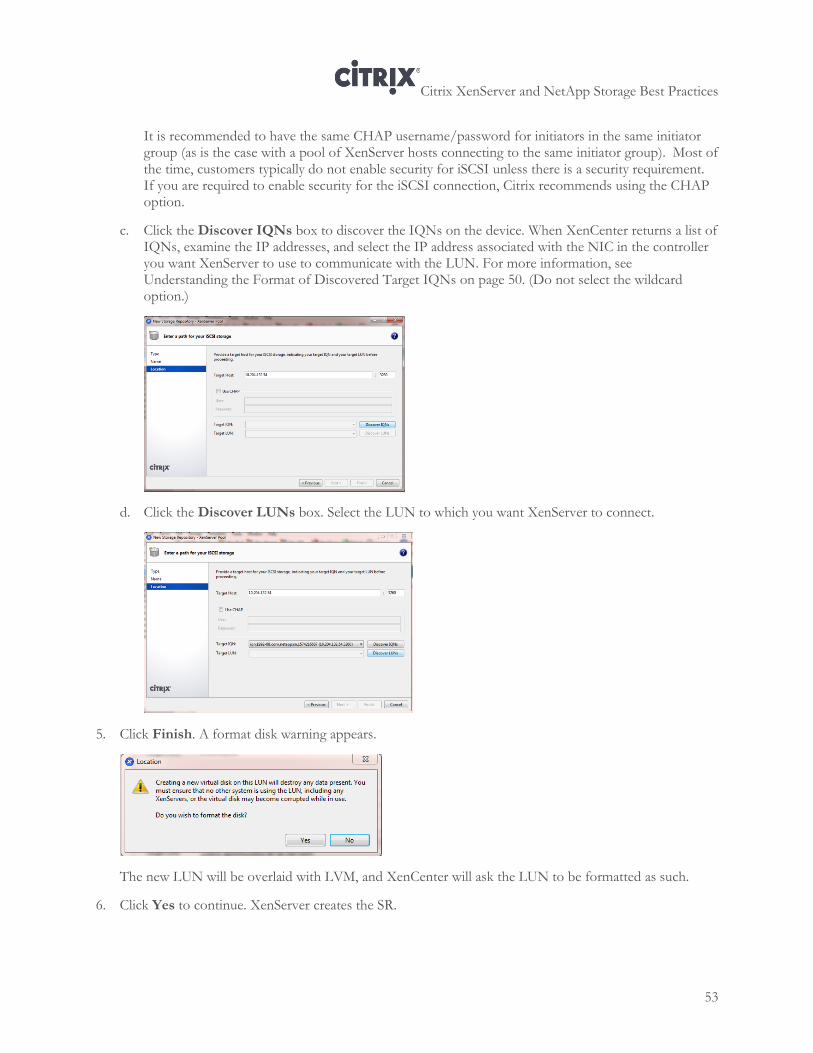
Citrix XenServer and NetApp Storage Best Practices
53
It is recommended to have the same CHAP username/password for initiators in the same initiator group (as is the case with a pool of XenServer hosts connecting to the same initiator group). Most of the time, customers typically do not enable security for iSCSI unless there is a security requirement. If you are required to enable security for the iSCSI connection, Citrix recommends using the CHAP option.
c. Click the Discover IQNs box to discover the IQNs on the device. When XenCenter returns a list of IQNs, examine the IP addresses, and select the IP address associated with the NIC in the controller you want XenServer to use to communicate with the LUN. For more information, see Understanding the Format of Discovered Target IQNs on page 50. (Do not select the wildcard option.)
d. Click the Discover LUNs box. Select the LUN to which you want XenServer to connect.
5. Click Finish. A format disk warning appears.
The new LUN will be overlaid with LVM, and XenCenter will ask the LUN to be formatted as such.
6. Click Yes to continue. XenServer creates the SR.
Citrix XenServer and NetApp Storage Best Practices
54
Chapter 7: Creating an iSCSI Hardware SR
This chapter provides information about creating iSCSI hardware SR and includes the following topics:
Configuring an HBA
Creating an initiator group
Creating a LUN for iSCSI hardware
Adding a persistent iSCSI target to the HBA ports
Enabling multipathing
Creating an iSCSI SR over HBA
Overview
This chapter explains how to create an SR when you want to use HBAs to connect to the storage over the iSCSI protocol.
This chapter provides an example of how to create an iSCSI hardware SR using a QLogic HBA as an example. If your HBA is from another vendor, use this example as a general guide, but use an HBA configuration utility from your HBA vendor and follow their instructions for configuring the HBA.
When you are configuring an iSCSI HBA SR, you must make the HBA aware of the storage controller and restrict the LUN so that it cannot accept connections from any other hosts other than the HBAs you specify (through LUN masking).
This means that you need to:
1. Create a persistent iSCSI target on each port on the HBA (by providing each port on the HBA with the IQNs from the storage controller).
2. Specify the IQNs that are allowed to connect to the storage target by creating an initiator group that has the IQNs from authorized HBAs in it.
Note: In order to use an HBA for iSCSI storage, XenServer must detect the HBA as an iSCSI port.
Citrix XenServer and NetApp Storage Best Practices
55
Overall Process for iSCSI Hardware SRs
Before you can create an iSCSI hardware SR, you must install the HBA and configure it. This section explains the process from a high level.
1. Enable the iSCSI service on storage. See “Enabling the iSCSI service on the NetApp ” on page 47.
2. Configure the HBA on each host.
a. Set the IP networking configuration for each port on the HBA.
b. Add a persistent iSCSI target to each port of the HBA.
c. Rescan the HBA controller to display the available LUNs.
d. Note the IQN for the HBA. If an IQN is not already set on the HBA, you might need to configure an IQN for the HBA: in this case, see the HBA vendor’s documentation.
3. Create an initiator group.
4. Create a new LUN specifying the HBA IQNs for each host in the pool.
5. Create the HBA SR.
As an example, this guide uses a QLogic iSCSI HBA and the CLI iscli command.
XenServer HBA Support
XenServer supports the several different brands of HBAs, as listed in the storage controllers section of the XenServer Hardware Compatibility List (http://hcl.xensource.com/HCLHome.aspx). However, each XenServer host contains utilities for configuring the following HBAs:
QLogic. XenServer includes the iscli command, which is found at /opt/QLogic_Corporation/SANsurferiCLI/iscli.
Emulex. XenServer includes the hbanywhere utility, which is found at /usr/sbin/hbanyware.
Access these utilities by running them from the CLI on the XenServer host.
Configuring an HBA
Configuring an HBA is a two-step process:
1. Set the IP networking configuration for the HBA. You can set either a static or DHCP IP address.
2. Add a persistent iSCSI target to each port on the HBA.
Because storage is a pool-wide feature, you need to perform these steps for each HBA you want to configure on each host in the pool.
If you are using an Emulex HBA or another brand on the XenServer Hardware Compatibility List, see the HBA’s documentation for the details of the HBA-side configuration.
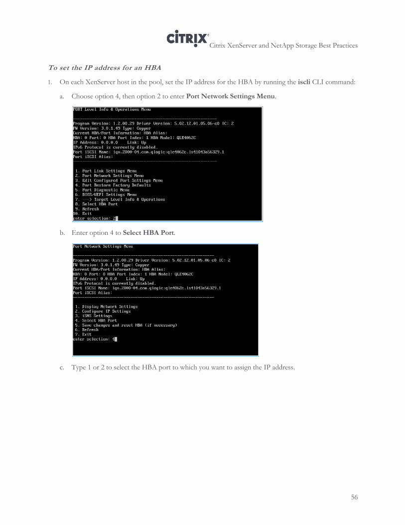
Citrix XenServer and NetApp Storage Best Practices
56
To set the IP address for an HBA
1. On each XenServer host in the pool, set the IP address for the HBA by running the iscli CLI command:
a. Choose option 4, then option 2 to enter Port Network Settings Menu.
b. Enter option 4 to Select HBA Port.
c. Type 1 or 2 to select the HBA port to which you want to assign the IP address.
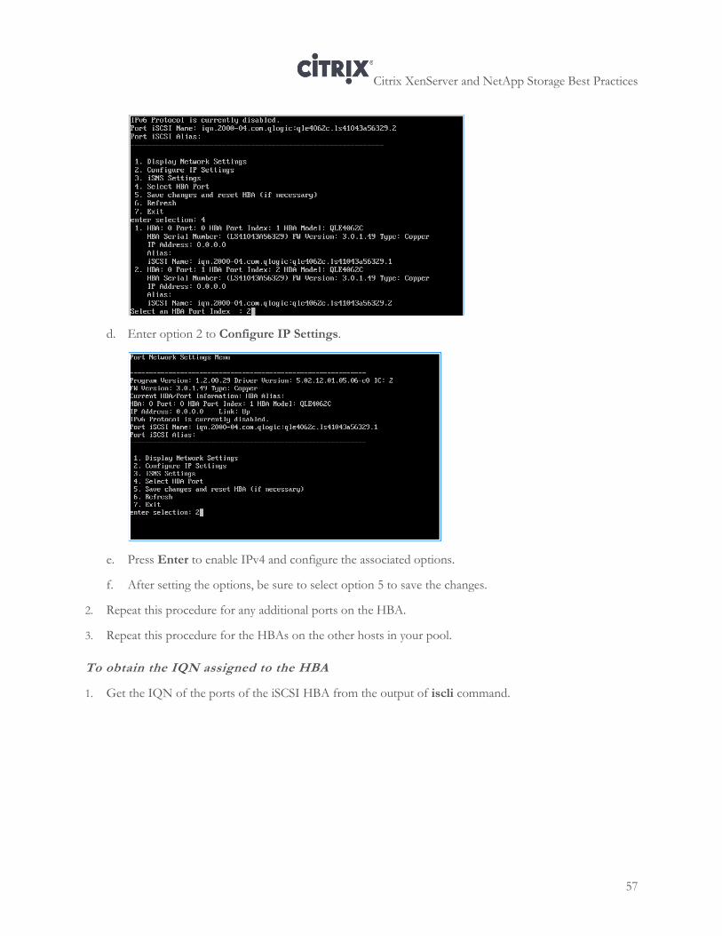
Citrix XenServer and NetApp Storage Best Practices
57
d. Enter option 2 to Configure IP Settings.
e. Press Enter to enable IPv4 and configure the associated options.
f. After setting the options, be sure to select option 5 to save the changes.
2. Repeat this procedure for any additional ports on the HBA.
3. Repeat this procedure for the HBAs on the other hosts in your pool.
To obtain the IQN assigned to the HBA
1. Get the IQN of the ports of the iSCSI HBA from the output of iscli command.
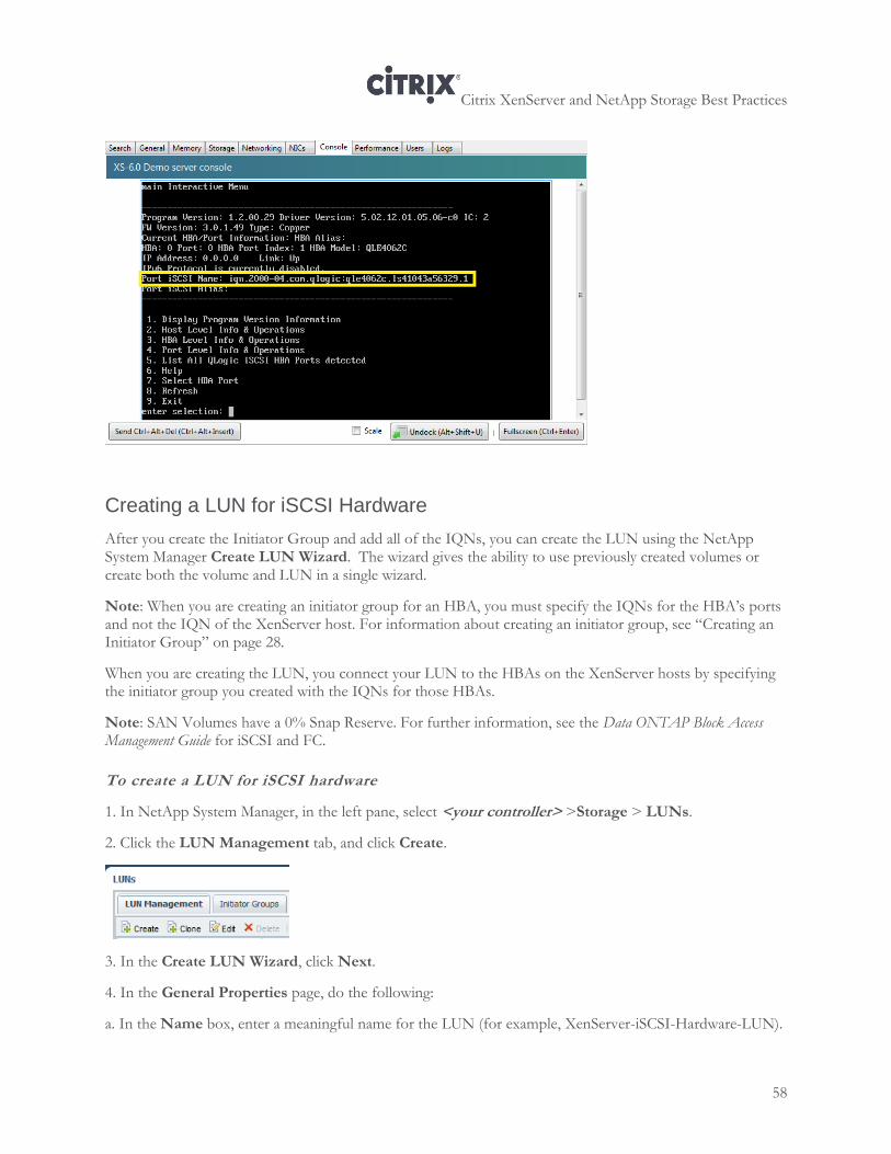
Citrix XenServer and NetApp Storage Best Practices
58
Creating a LUN for iSCSI Hardware
After you create the Initiator Group and add all of the IQNs, you can create the LUN using the NetApp System Manager Create LUN Wizard. The wizard gives the ability to use previously created volumes or create both the volume and LUN in a single wizard.
Note: When you are creating an initiator group for an HBA, you must specify the IQNs for the HBA’s ports and not the IQN of the XenServer host. For information about creating an initiator group, see “Creating an Initiator Group” on page 28.
When you are creating the LUN, you connect your LUN to the HBAs on the XenServer hosts by specifying the initiator group you created with the IQNs for those HBAs.
Note: SAN Volumes have a 0% Snap Reserve. For further information, see the Data ONTAP Block Access Management Guide for iSCSI and FC.
To create a LUN for iSCSI hardware
1. In NetApp System Manager, in the left pane, select <your controller> >Storage > LUNs.
2. Click the LUN Management tab, and click Create.
3. In the Create LUN Wizard, click Next.
4. In the General Properties page, do the following:
a. In the Name box, enter a meaningful name for the LUN (for example, XenServer-iSCSI-Hardware-LUN).
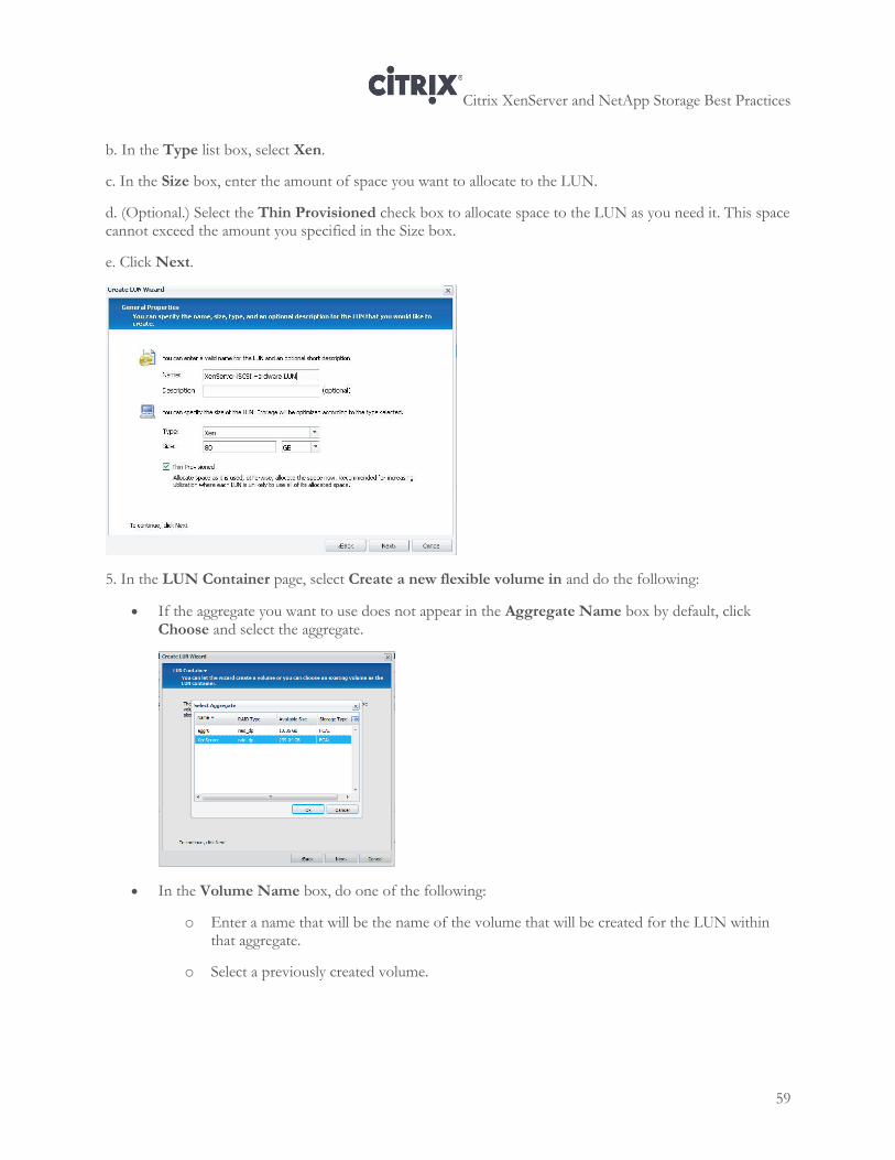
Citrix XenServer and NetApp Storage Best Practices
59
b. In the Type list box, select Xen.
c. In the Size box, enter the amount of space you want to allocate to the LUN.
d. (Optional.) Select the Thin Provisioned check box to allocate space to the LUN as you need it. This space cannot exceed the amount you specified in the Size box.
e. Click Next.
5. In the LUN Container page, select Create a new flexible volume in and do the following:
If the aggregate you want to use does not appear in the Aggregate Name box by default, click Choose and select the aggregate.
In the Volume Name box, do one of the following:
o Enter a name that will be the name of the volume that will be created for the LUN within that aggregate.
o Select a previously created volume.
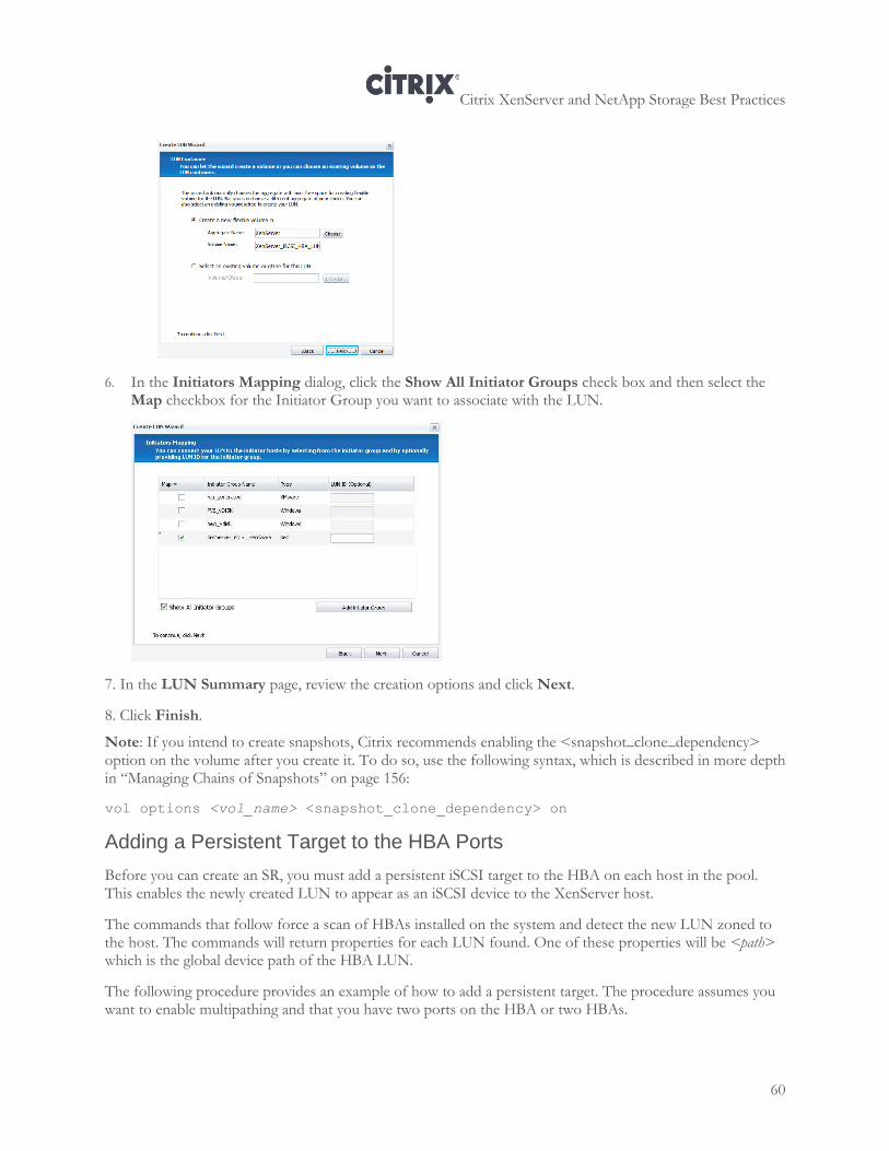
Citrix XenServer and NetApp Storage Best Practices
60
6. In the Initiators Mapping dialog, click the Show All Initiator Groups check box and then select the Map checkbox for the Initiator Group you want to associate with the LUN.
7. In the LUN Summary page, review the creation options and click Next.
8. Click Finish.
Note: If you intend to create snapshots, Citrix recommends enabling the <snapshot_clone_dependency> option on the volume after you create it. To do so, use the following syntax, which is described in more depth in “Managing Chains of Snapshots” on page 156:
vol options <vol_name> <snapshot_clone_dependency> on
Adding a Persistent Target to the HBA Ports
Before you can create an SR, you must add a persistent iSCSI target to the HBA on each host in the pool. This enables the newly created LUN to appear as an iSCSI device to the XenServer host.
The commands that follow force a scan of HBAs installed on the system and detect the new LUN zoned to the host. The commands will return properties for each LUN found. One of these properties will be <path> which is the global device path of the HBA LUN.
The following procedure provides an example of how to add a persistent target. The procedure assumes you want to enable multipathing and that you have two ports on the HBA or two HBAs.
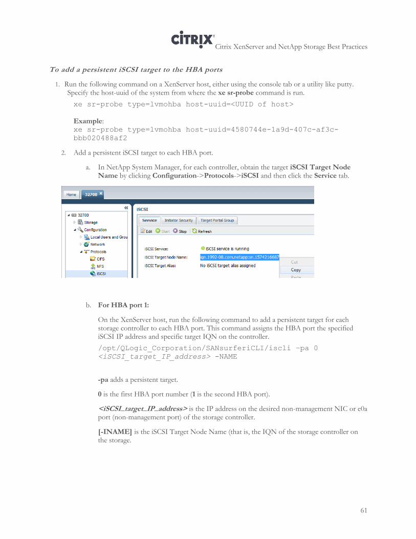
Citrix XenServer and NetApp Storage Best Practices
61
To add a persistent iSCSI target to the HBA ports
1. Run the following command on a XenServer host, either using the console tab or a utility like putty. Specify the host-uuid of the system from where the xe sr-probe command is run.
xe sr-probe type=lvmohba host-uuid=<UUID of host>
Example: xe sr-probe type=lvmohba host-uuid=4580744e-1a9d-407c-af3c-
bbb020488af2
2. Add a persistent iSCSI target to each HBA port.
a. In NetApp System Manager, for each controller, obtain the target iSCSI Target Node Name by clicking Configuration->Protocols->iSCSI and then click the Service tab.
b. For HBA port 1:
On the XenServer host, run the following command to add a persistent target for each storage controller to each HBA port. This command assigns the HBA port the specified iSCSI IP address and specific target IQN on the controller.
/opt/QLogic_Corporation/SANsurferiCLI/iscli –pa 0
<iSCSI_target_IP_address> -NAME
-pa adds a persistent target.
0 is the first HBA port number (1 is the second HBA port).
<iSCSI_target_IP_address> is the IP address on the desired non-management NIC or e0a port (non-management port) of the storage controller.
[-INAME] is the iSCSI Target Node Name (that is, the IQN of the storage controller on the storage.
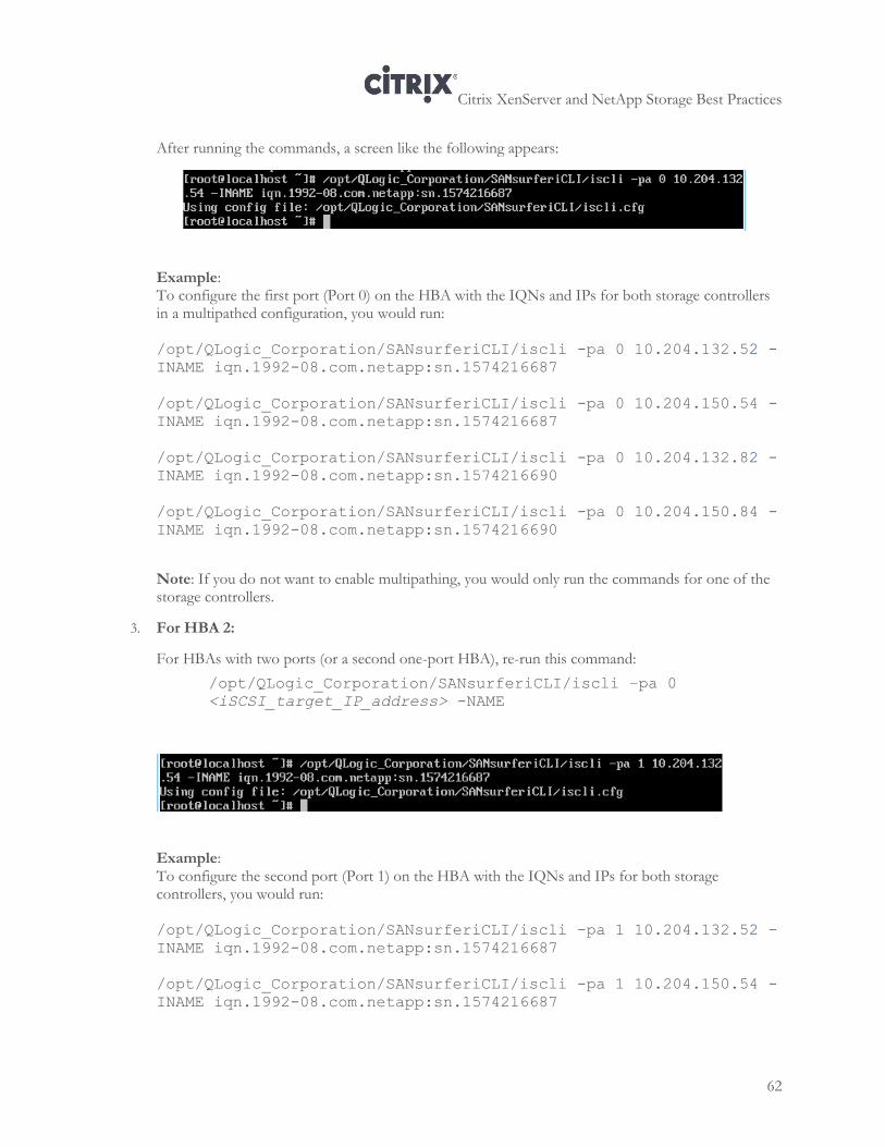
Citrix XenServer and NetApp Storage Best Practices
62
After running the commands, a screen like the following appears:
Example: To configure the first port (Port 0) on the HBA with the IQNs and IPs for both storage controllers in a multipathed configuration, you would run: /opt/QLogic_Corporation/SANsurferiCLI/iscli -pa 0 10.204.132.52 -
INAME iqn.1992-08.com.netapp:sn.1574216687
/opt/QLogic_Corporation/SANsurferiCLI/iscli -pa 0 10.204.150.54 -
INAME iqn.1992-08.com.netapp:sn.1574216687
/opt/QLogic_Corporation/SANsurferiCLI/iscli -pa 0 10.204.132.82 -
INAME iqn.1992-08.com.netapp:sn.1574216690
/opt/QLogic_Corporation/SANsurferiCLI/iscli -pa 0 10.204.150.84 -
INAME iqn.1992-08.com.netapp:sn.1574216690
Note: If you do not want to enable multipathing, you would only run the commands for one of the storage controllers.
3. For HBA 2:
For HBAs with two ports (or a second one-port HBA), re-run this command:
/opt/QLogic_Corporation/SANsurferiCLI/iscli –pa 0
<iSCSI_target_IP_address> -NAME
Example: To configure the second port (Port 1) on the HBA with the IQNs and IPs for both storage controllers, you would run: /opt/QLogic_Corporation/SANsurferiCLI/iscli -pa 1 10.204.132.52 -
INAME iqn.1992-08.com.netapp:sn.1574216687
/opt/QLogic_Corporation/SANsurferiCLI/iscli -pa 1 10.204.150.54 -
INAME iqn.1992-08.com.netapp:sn.1574216687
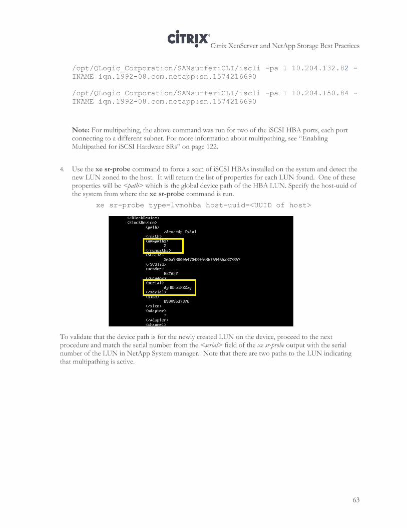
Citrix XenServer and NetApp Storage Best Practices
63
/opt/QLogic_Corporation/SANsurferiCLI/iscli -pa 1 10.204.132.82 -
INAME iqn.1992-08.com.netapp:sn.1574216690
/opt/QLogic_Corporation/SANsurferiCLI/iscli -pa 1 10.204.150.84 -
INAME iqn.1992-08.com.netapp:sn.1574216690
Note: For multipathing, the above command was run for two of the iSCSI HBA ports, each port connecting to a different subnet. For more information about multipathing, see “Enabling Multipathed for iSCSI Hardware SRs” on page 122.
4. Use the xe sr-probe command to force a scan of iSCSI HBAs installed on the system and detect the
new LUN zoned to the host. It will return the list of properties for each LUN found. One of these properties will be <path> which is the global device path of the HBA LUN. Specify the host-uuid of the system from where the xe sr-probe command is run.
xe sr-probe type=lvmohba host-uuid=<UUID of host>
To validate that the device path is for the newly created LUN on the device, proceed to the next procedure and match the serial number from the <serial> field of the xe sr-probe output with the serial number of the LUN in NetApp System manager. Note that there are two paths to the LUN indicating that multipathing is active.
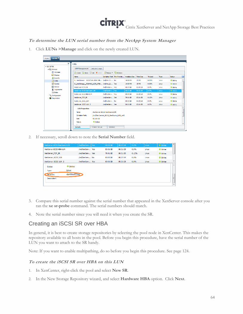
Citrix XenServer and NetApp Storage Best Practices
64
To determine the LUN serial number from the NetApp System Manager
1. Click LUNs >Manage and click on the newly created LUN.
2. If necessary, scroll down to note the Serial Number field.
3. Compare this serial number against the serial number that appeared in the XenServer console after you ran the xe sr-probe command. The serial numbers should match.
4. Note the serial number since you will need it when you create the SR.
Creating an iSCSI SR over HBA
In general, it is best to create storage repositories by selecting the pool node in XenCenter. This makes the repository available to all hosts in the pool. Before you begin this procedure, have the serial number of the LUN you want to attach to the SR handy.
Note: If you want to enable multipathing, do so before you begin this procedure. See page 124.
To create the iSCSI SR over HBA on this LUN
1. In XenCenter, right-click the pool and select New SR.
2. In the New Storage Repository wizard, and select Hardware HBA option. Click Next.
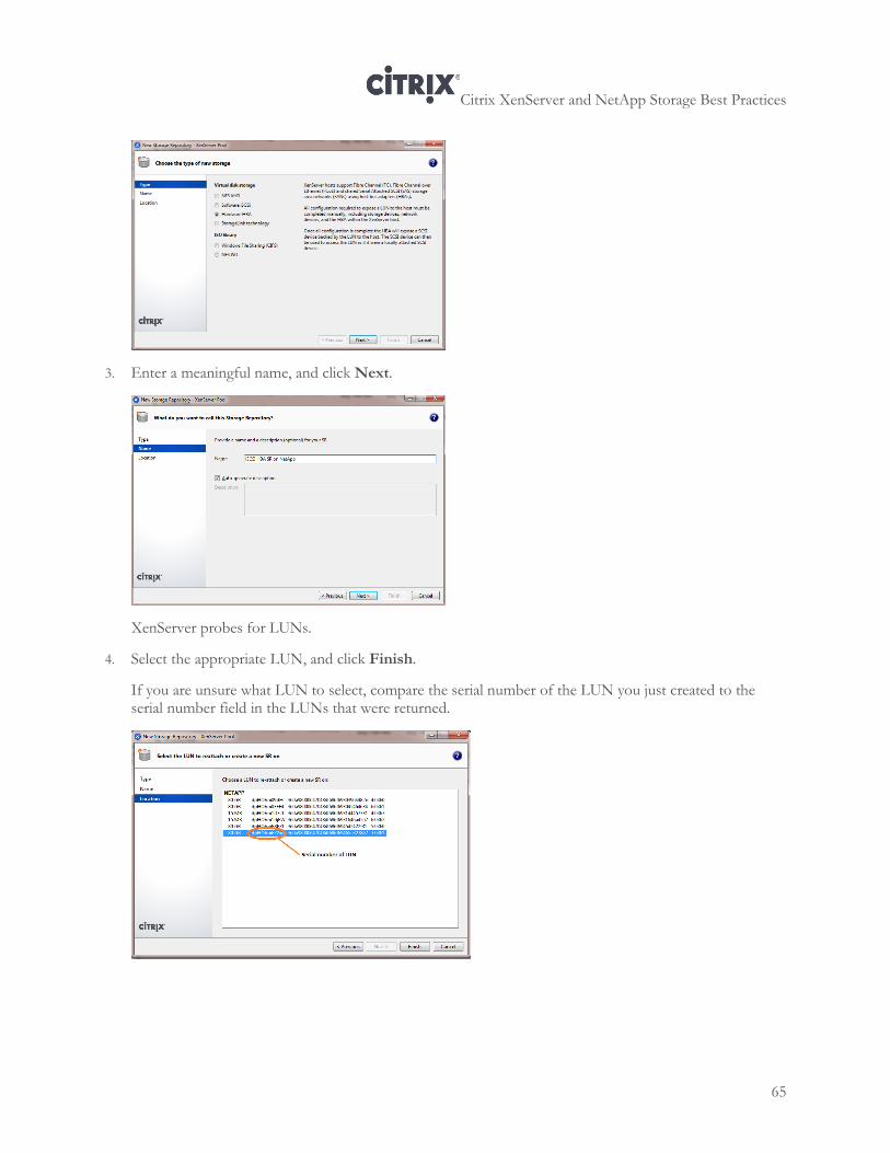
Citrix XenServer and NetApp Storage Best Practices
65
3. Enter a meaningful name, and click Next.
XenServer probes for LUNs.
4. Select the appropriate LUN, and click Finish.
If you are unsure what LUN to select, compare the serial number of the LUN you just created to the serial number field in the LUNs that were returned.
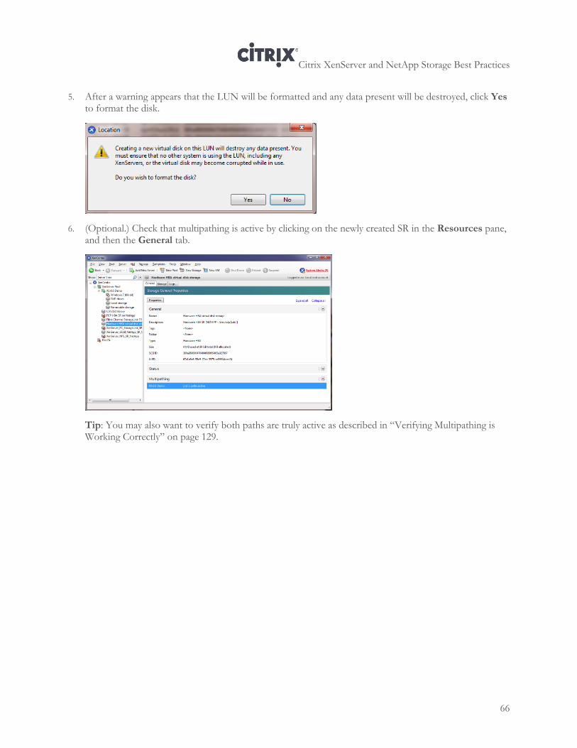
Citrix XenServer and NetApp Storage Best Practices
66
5. After a warning appears that the LUN will be formatted and any data present will be destroyed, click Yes to format the disk.
6. (Optional.) Check that multipathing is active by clicking on the newly created SR in the Resources pane, and then the General tab.
Tip: You may also want to verify both paths are truly active as described in “Verifying Multipathing is Working Correctly” on page 129.
Citrix XenServer and NetApp Storage Best Practices
67
Chapter 8: XenServer Fibre Channel Storage Configuration
This chapter provides information about configuring Fibre Channel storage for XenServer, including information about the following:
Using XenServer with multiple clustered storage filers
Configuring the Fibre Channel ports on the filer as targets
Retrieving the WWPN for the HBAs on the host
Creating an initiator group for Fibre Channel in NetApp System Manager
Creating a LUN for Fibre Channel in NetApp System Manager
Configuring a XenServer Fibre Channel SR
Overview
When configuring Fibre Channel storage repositories for XenServer, there are two major configuration techniques:
Using the SR wizard and creating the SR using the HBA option. This requires creating a LUN using NetApp System Manager first.
Using the StorageLink feature in the SR wizard and creating the LUN on the storage at the same time as you create the SR.
In addition, other design choices, such as if you have clustered NetApp filers or have ALUA enabled, will
affect your configuration process. Likewise, if you want to configure multipathing, Citrix recommends doing
so before you create the SR.
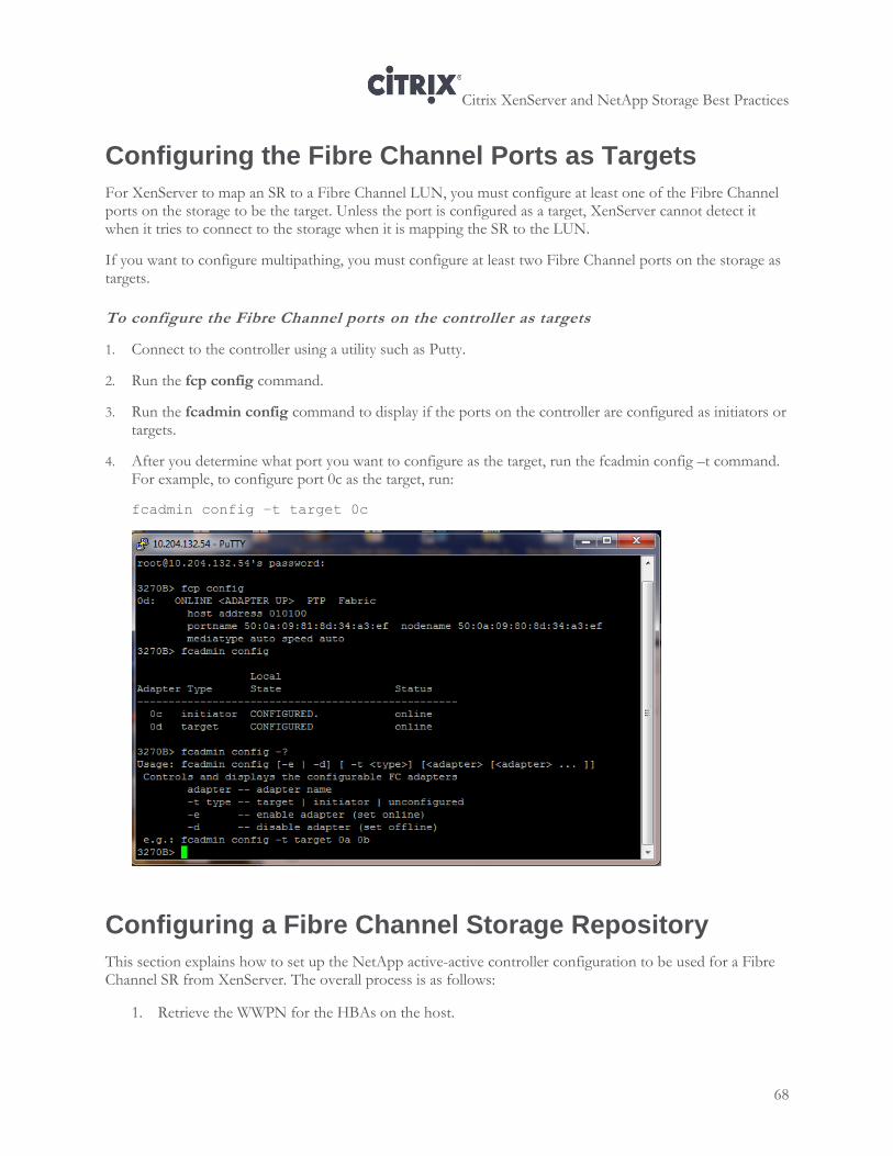
Citrix XenServer and NetApp Storage Best Practices
68
Configuring the Fibre Channel Ports as Targets
For XenServer to map an SR to a Fibre Channel LUN, you must configure at least one of the Fibre Channel ports on the storage to be the target. Unless the port is configured as a target, XenServer cannot detect it when it tries to connect to the storage when it is mapping the SR to the LUN.
If you want to configure multipathing, you must configure at least two Fibre Channel ports on the storage as targets.
To configure the Fibre Channel ports on the controller as targets
1. Connect to the controller using a utility such as Putty.
2. Run the fcp config command.
3. Run the fcadmin config command to display if the ports on the controller are configured as initiators or targets.
4. After you determine what port you want to configure as the target, run the fcadmin config –t command. For example, to configure port 0c as the target, run:
fcadmin config –t target 0c
Configuring a Fibre Channel Storage Repository
This section explains how to set up the NetApp active-active controller configuration to be used for a Fibre Channel SR from XenServer. The overall process is as follows:
1. Retrieve the WWPN for the HBAs on the host.
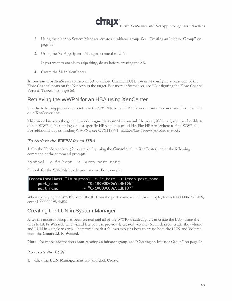
Citrix XenServer and NetApp Storage Best Practices
69
2. Using the NetApp System Manager, create an initiator group. See “Creating an Initiator Group” on
page 28.
3. Using the NetApp System Manager, create the LUN.
If you want to enable multipathing, do so before creating the SR.
4. Create the SR in XenCenter.
Important: For XenServer to map an SR to a Fibre Channel LUN, you must configure at least one of the Fibre Channel ports on the NetApp as the target. For more information, see “Configuring the Fibre Channel Ports as Targets” on page 68.
Retrieving the WWPN for an HBA using XenCenter
Use the following procedure to retrieve the WWPNs for an HBA. You can run this command from the CLI on a XenServer host.
This procedure uses the generic, vendor-agnostic systool command. However, if desired, you may be able to obtain WWPNs by running vendor-specific HBA utilities or utilities like HBAAnywhere to find WWPNs. For additional tips on finding WWPNs, see CTX118791--Multipathing Overview for XenServer 5.0.
To retrieve the WWPN for an HBA
1. On the XenServer host (for example, by using the Console tab in XenCenter), enter the following command at the command prompt:
systool -c fc_host -v |grep port_name
2. Look for the WWPNs beside port_name. For example:
When specifying the WWPN, omit the 0x from the port_name value. For example, for 0x10000000c9adbf06, enter 10000000c9adbf06.
Creating the LUN in System Manager
After the initiator group has been created and all of the WWPNs added, you can create the LUN using the Create LUN Wizard. The wizard lets you use previously created volumes (or, if desired, create the volume and LUN in a single wizard). The procedure that follows explains how to create both the LUN and Volume from the Create LUN Wizard.
Note: For more information about creating an initiator group, see “Creating an Initiator Group” on page 28.
To create the LUN
1. Click the LUN Management tab, and click Create.
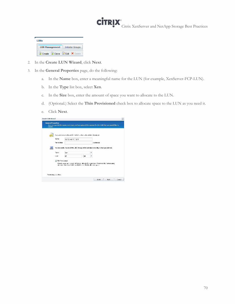
Citrix XenServer and NetApp Storage Best Practices
70
2. In the Create LUN Wizard, click Next.
3. In the General Properties page, do the following:
a. In the Name box, enter a meaningful name for the LUN (for example, XenServer-FCP-LUN).
b. In the Type list box, select Xen.
c. In the Size box, enter the amount of space you want to allocate to the LUN.
d. (Optional.) Select the Thin Provisioned check box to allocate space to the LUN as you need it.
e. Click Next.
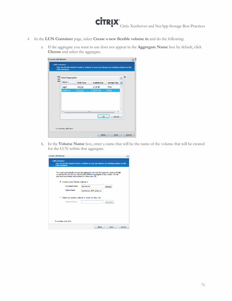
Citrix XenServer and NetApp Storage Best Practices
71
4. In the LUN Container page, select Create a new flexible volume in and do the following:
a. If the aggregate you want to use does not appear in the Aggregate Name box by default, click Choose and select the aggregate.
b. In the Volume Name box, enter a name that will be the name of the volume that will be created for the LUN within that aggregate.
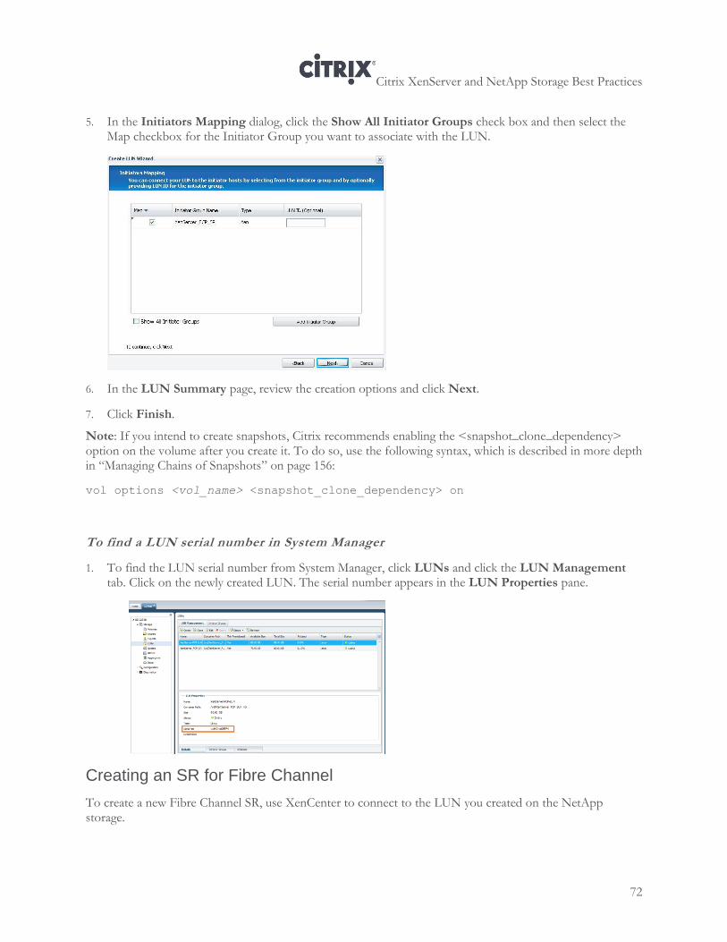
Citrix XenServer and NetApp Storage Best Practices
72
5. In the Initiators Mapping dialog, click the Show All Initiator Groups check box and then select the Map checkbox for the Initiator Group you want to associate with the LUN.
6. In the LUN Summary page, review the creation options and click Next.
7. Click Finish.
Note: If you intend to create snapshots, Citrix recommends enabling the <snapshot_clone_dependency> option on the volume after you create it. To do so, use the following syntax, which is described in more depth in “Managing Chains of Snapshots” on page 156:
vol options <vol_name> <snapshot_clone_dependency> on
To find a LUN serial number in System Manager
1. To find the LUN serial number from System Manager, click LUNs and click the LUN Management tab. Click on the newly created LUN. The serial number appears in the LUN Properties pane.
Creating an SR for Fibre Channel
To create a new Fibre Channel SR, use XenCenter to connect to the LUN you created on the NetApp storage.
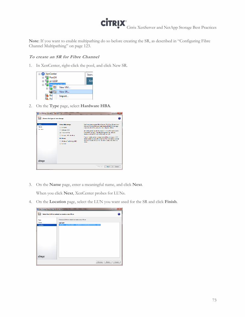
Citrix XenServer and NetApp Storage Best Practices
73
Note: If you want to enable multipathing do so before creating the SR, as described in “Configuring Fibre Channel Multipathing” on page 123.
To create an SR for Fibre Channel
1. In XenCenter, right-click the pool, and click New SR.
2. On the Type page, select Hardware HBA.
3. On the Name page, enter a meaningful name, and click Next.
When you click Next, XenCenter probes for LUNs.
4. On the Location page, select the LUN you want used for the SR and click Finish.
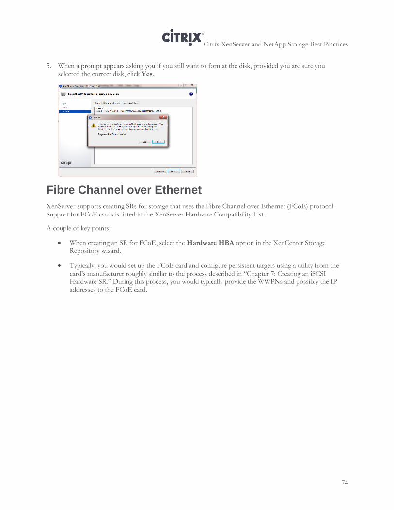
Citrix XenServer and NetApp Storage Best Practices
74
5. When a prompt appears asking you if you still want to format the disk, provided you are sure you selected the correct disk, click Yes.
Fibre Channel over Ethernet
XenServer supports creating SRs for storage that uses the Fibre Channel over Ethernet (FCoE) protocol. Support for FCoE cards is listed in the XenServer Hardware Compatibility List.
A couple of key points:
When creating an SR for FCoE, select the Hardware HBA option in the XenCenter Storage Repository wizard.
Typically, you would set up the FCoE card and configure persistent targets using a utility from the card’s manufacturer roughly similar to the process described in “Chapter 7: Creating an iSCSI Hardware SR.” During this process, you would typically provide the WWPNs and possibly the IP addresses to the FCoE card.
Citrix XenServer and NetApp Storage Best Practices
75
Chapter 9: Configuring Storage with StorageLink
This chapter contains information about StorageLink, including the following:
An explanation of StorageLink and different ways to use it, including best practices
StorageLink requirements
An overview of how to configure StorageLink SRs
Overview
StorageLink is a XenServer feature that provides an easy way for people not comfortable with storage configuration to create a volume and a LUN from within XenCenter. If you use StorageLink, XenServer interacts with the NetApp storage on your behalf to create the volume and LUN for you. You specify the options you want in the LUN and volume, such as deduplication and thin provisioning, when you create the SR in XenCenter.
StorageLink also provides benefits for experienced administrators. A StorageLink SR provides direct access to high-performance storage, allowing the VMs in your XenServer environment to benefit from array-side enterprise storage services such as replication, de-duplication, thin provisioning, snapshots and cloning, data protection, and performance optimization.
As described in more depth in the sections that follow, if desired, you can create the volume on the storage before using StorageLink. This lets you control the ratio of LUNs to volumes and create meaningful names for volumes while accessing the storage directly.
StorageLink SRs use storage adapters to access different storage arrays on all common storage technologies including both NAS and SAN over either Fibre Channel or iSCSI. The features available on a given StorageLink SR depend on the capabilities of the underlying array. StorageLink SRs can co-exist with other SR types on the same storage array hardware, and multiple StorageLink SRs can be defined within the same resource pool.
StorageLink Requirements
StorageLink is supported for Fibre Channel and iSCSI protocols for both NAS and SAN.
Citrix XenServer and NetApp Storage Best Practices
76
Requirements
XenServer Enterprise or Platinum edition license
httpd must be enabled on the NetApp storage
Fibre Channel. When creating a Fibre Channel SR through StorageLink, a NetApp license for iSCSI must be present on the storage or ONTAP 8.1 is required.
Note: As of XenServer 6.0, StorageLink is now integrated in XenServer. The StorageLink Gateway is not available or supported for XenServer 6.0.
Limitations
StorageLink SRs are not supported with XenDesktop.
Configuring StorageLink Storage Repositories
You can create NetApp StorageLink SRs for both NAS and SAN over either Fibre Channel or iSCSI. Depending on your environment and goals, StorageLink provides three advantages:
StorageLink SRs use the storage management software to access the storage.
StorageLink simplifies the storage configuration process. For example, when you create a NetApp StorageLink SR from XenCenter, StorageLink automatically creates the LUN, volume, and initiator group for you. This means you do not have to go in to the storage management software to create these objects. However, you do need to have created an aggregate before you run the XenCenter SR wizard.
Every VDI created gets its own LUN. All StorageLink SRs use a LUN-per-VDI model where a new LUN is provisioned for each virtual disk (VDI). By default, the XenServer block device-based storage inserts a Logical Volume Manager on a disk, either a locally attached device (LVM type SR) or a SAN attached LUN over either Fibre Channel (LVMoHBA type SR), iSCSI (LVMoISCSI type SR) or SAS (LVMoHBA type Sr). When you use StorageLink to configure an SR, LUNs are directly mapped to virtual machines as VDIs. As a result, the array storage abstraction matches the VDI storage abstraction, which is helpful in environments that manage storage provisioning at an array level.
StorageLink can co-exist with other SR types on the same storage hardware. Likewise, you can define multiple StorageLink SRs in the same resource pool.
The features available in a given StorageLink SR depend on the capabilities of the underlying storage.
When StorageLink creates an SR (and the associated LUN and volume), StorageLink automatically creates the initiator group with the Linux operating system. Manually configuring initiator groups with other operating systems is not recommended.
Note: Creating a Fibre Channel SR using StorageLink requires that the storage has an iSCSI license on it or be running ONTAP 8.1. If neither applies, create the SR using the standard SR creation process (without StorageLink) in XenCenter.
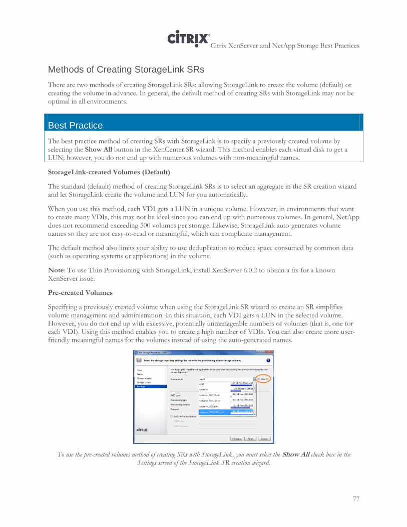
Citrix XenServer and NetApp Storage Best Practices
77
Methods of Creating StorageLink SRs
There are two methods of creating StorageLink SRs: allowing StorageLink to create the volume (default) or creating the volume in advance. In general, the default method of creating SRs with StorageLink may not be optimal in all environments.
Best Practice
The best practice method of creating SRs with StorageLink is to specify a previously created volume by selecting the Show All button in the XenCenter SR wizard. This method enables each virtual disk to get a LUN; however, you do not end up with numerous volumes with non-meaningful names.
StorageLink-created Volumes (Default)
The standard (default) method of creating StorageLink SRs is to select an aggregate in the SR creation wizard and let StorageLink create the volume and LUN for you automatically.
When you use this method, each VDI gets a LUN in a unique volume. However, in environments that want to create many VDIs, this may not be ideal since you can end up with numerous volumes. In general, NetApp does not recommend exceeding 500 volumes per storage. Likewise, StorageLink auto-generates volume names so they are not easy-to-read or meaningful, which can complicate management.
The default method also limits your ability to use deduplication to reduce space consumed by common data (such as operating systems or applications) in the volume.
Note: To use Thin Provisioning with StorageLink, install XenServer 6.0.2 to obtain a fix for a known XenServer issue.
Pre-created Volumes
Specifying a previously created volume when using the StorageLink SR wizard to create an SR simplifies volume management and administration. In this situation, each VDI gets a LUN in the selected volume. However, you do not end up with excessive, potentially unmanageable numbers of volumes (that is, one for each VDI). Using this method enables you to create a high number of VDIs. You can also create more user-friendly meaningful names for the volumes instead of using the auto-generated names.
To use the pre-created volumes method of creating SRs with StorageLink, you must select the Show All check box in the Settings screen of the StorageLink SR creation wizard.
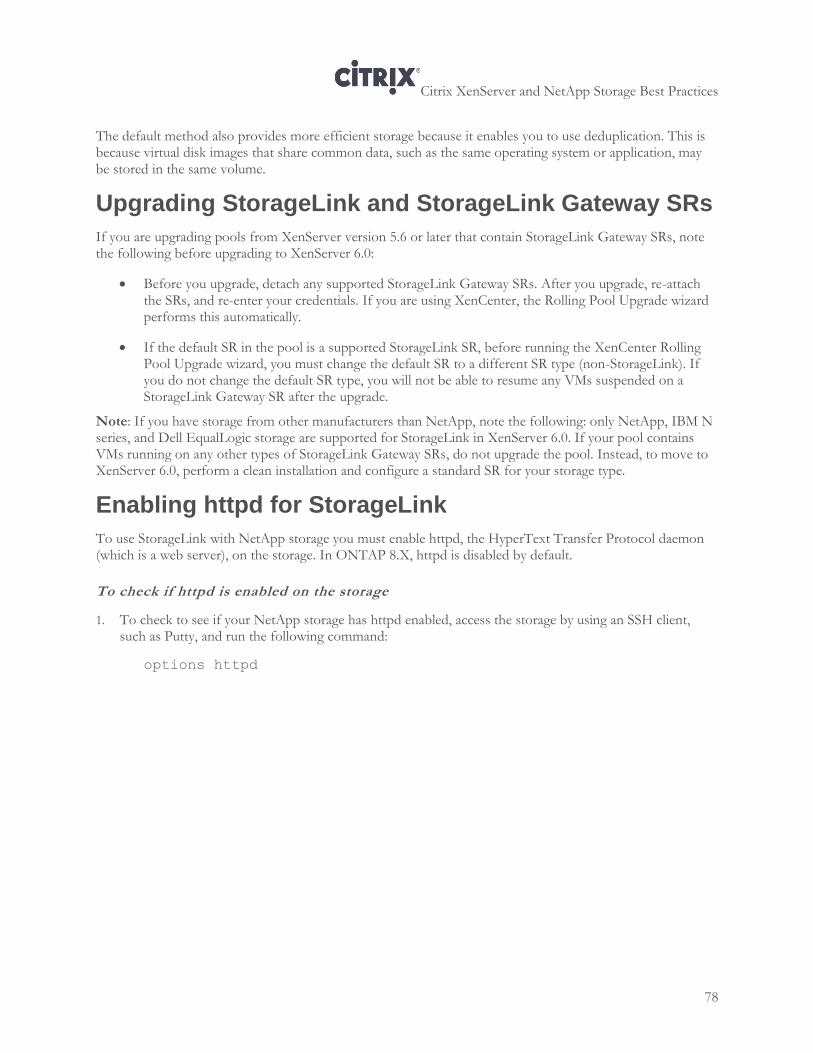
Citrix XenServer and NetApp Storage Best Practices
78
The default method also provides more efficient storage because it enables you to use deduplication. This is because virtual disk images that share common data, such as the same operating system or application, may be stored in the same volume.
Upgrading StorageLink and StorageLink Gateway SRs
If you are upgrading pools from XenServer version 5.6 or later that contain StorageLink Gateway SRs, note the following before upgrading to XenServer 6.0:
Before you upgrade, detach any supported StorageLink Gateway SRs. After you upgrade, re-attach the SRs, and re-enter your credentials. If you are using XenCenter, the Rolling Pool Upgrade wizard performs this automatically.
If the default SR in the pool is a supported StorageLink SR, before running the XenCenter Rolling Pool Upgrade wizard, you must change the default SR to a different SR type (non-StorageLink). If you do not change the default SR type, you will not be able to resume any VMs suspended on a StorageLink Gateway SR after the upgrade.
Note: If you have storage from other manufacturers than NetApp, note the following: only NetApp, IBM N series, and Dell EqualLogic storage are supported for StorageLink in XenServer 6.0. If your pool contains VMs running on any other types of StorageLink Gateway SRs, do not upgrade the pool. Instead, to move to XenServer 6.0, perform a clean installation and configure a standard SR for your storage type.
Enabling httpd for StorageLink
To use StorageLink with NetApp storage you must enable httpd, the HyperText Transfer Protocol daemon (which is a web server), on the storage. In ONTAP 8.X, httpd is disabled by default.
To check if httpd is enabled on the storage
1. To check to see if your NetApp storage has httpd enabled, access the storage by using an SSH client, such as Putty, and run the following command:
options httpd
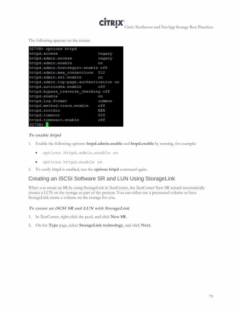
Citrix XenServer and NetApp Storage Best Practices
79
The following appears on the screen:
To enable httpd
1. Enable the following options: httpd.admin.enable and httpd.enable by running, for example:
options httpd.admin.enable on
options httpd.enable on
2. To verify httpd is enabled, run the options httpd command again.
Creating an iSCSI Software SR and LUN Using StorageLink
When you create an SR by using StorageLink in XenCenter, the XenCenter New SR wizard automatically creates a LUN on the storage as part of the process. You can either use a precreated volume or have StorageLink create a volume on the storage for you.
To create an iSCSI SR and LUN with StorageLink
1. In XenCenter, right-click the pool, and click New SR.
2. On the Type page, select StorageLink technology, and click Next.
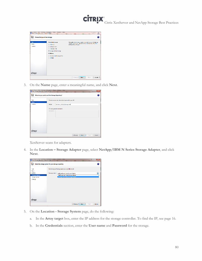
Citrix XenServer and NetApp Storage Best Practices
80
3. On the Name page, enter a meaningful name, and click Next.
XenServer scans for adapters.
4. In the Location – Storage Adapter page, select NetApp/IBM N Series Storage Adapter, and click Next.
5. On the Location - Storage System page, do the following:
a. In the Array target box, enter the IP address for the storage controller. To find the IP, see page 16.
b. In the Credentials section, enter the User name and Password for the storage.
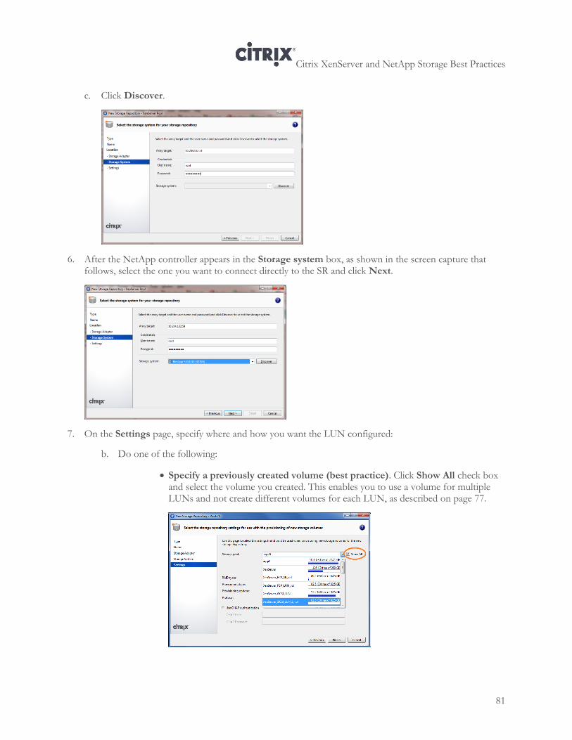
Citrix XenServer and NetApp Storage Best Practices
81
c. Click Discover.
6. After the NetApp controller appears in the Storage system box, as shown in the screen capture that follows, select the one you want to connect directly to the SR and click Next.
7. On the Settings page, specify where and how you want the LUN configured:
b. Do one of the following:
Specify a previously created volume (best practice). Click Show All check box and select the volume you created. This enables you to use a volume for multiple LUNs and not create different volumes for each LUN, as described on page 77.
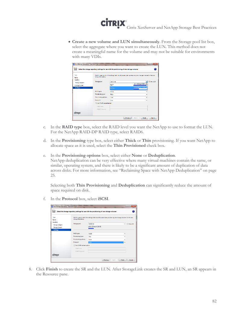
Citrix XenServer and NetApp Storage Best Practices
82
Create a new volume and LUN simultaneously. From the Storage pool list box, select the aggregate where you want to create the LUN. This method does not create a meaningful name for the volume and may not be suitable for environments with many VDIs.
c. In the RAID type box, select the RAID level you want the NetApp to use to format the LUN. For the NetApp RAID-DP RAID type, select RAID6.
d. In the Provisioning type box, select either Thick or Thin provisioning. If you want NetApp to allocate space as it is used, select the Thin Provisioned check box.
e. In the Provisioning options box, select either None or Deduplication. NetApp deduplication can be very effective where many virtual machines contain the same, or similar, operating system, and there is likely to be a significant amount of duplication of data across disks. For more information, see “Reclaiming Space with NetApp Deduplication” on page 25.
Selecting both Thin Provisioning and Deduplication can significantly reduce the amount of space required on disk.
f. In the Protocol box, select iSCSI.
8. Click Finish to create the SR and the LUN. After StorageLink creates the SR and LUN, an SR appears in the Resource pane.
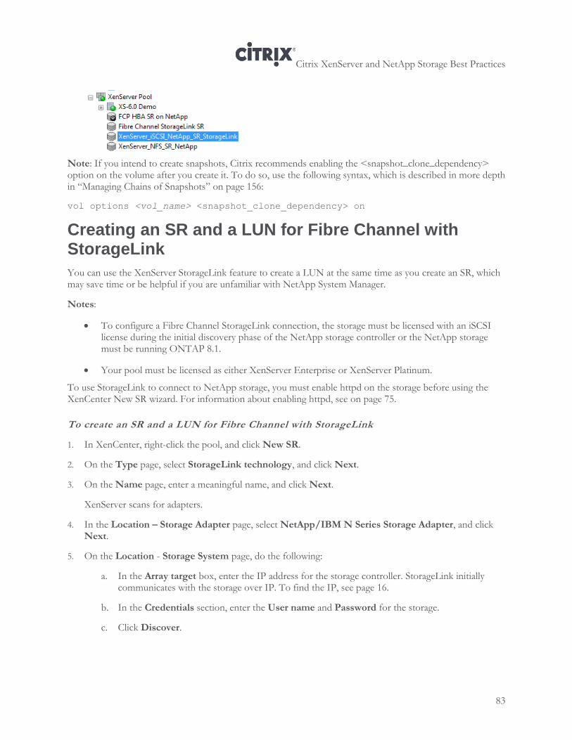
Citrix XenServer and NetApp Storage Best Practices
83
Note: If you intend to create snapshots, Citrix recommends enabling the <snapshot_clone_dependency> option on the volume after you create it. To do so, use the following syntax, which is described in more depth in “Managing Chains of Snapshots” on page 156:
vol options <vol_name> <snapshot_clone_dependency> on
Creating an SR and a LUN for Fibre Channel with StorageLink
You can use the XenServer StorageLink feature to create a LUN at the same time as you create an SR, which may save time or be helpful if you are unfamiliar with NetApp System Manager.
Notes:
To configure a Fibre Channel StorageLink connection, the storage must be licensed with an iSCSI license during the initial discovery phase of the NetApp storage controller or the NetApp storage must be running ONTAP 8.1.
Your pool must be licensed as either XenServer Enterprise or XenServer Platinum.
To use StorageLink to connect to NetApp storage, you must enable httpd on the storage before using the XenCenter New SR wizard. For information about enabling httpd, see on page 75.
To create an SR and a LUN for Fibre Channel with StorageLink
1. In XenCenter, right-click the pool, and click New SR.
2. On the Type page, select StorageLink technology, and click Next.
3. On the Name page, enter a meaningful name, and click Next.
XenServer scans for adapters.
4. In the Location – Storage Adapter page, select NetApp/IBM N Series Storage Adapter, and click Next.
5. On the Location - Storage System page, do the following:
a. In the Array target box, enter the IP address for the storage controller. StorageLink initially communicates with the storage over IP. To find the IP, see page 16.
b. In the Credentials section, enter the User name and Password for the storage.
c. Click Discover.
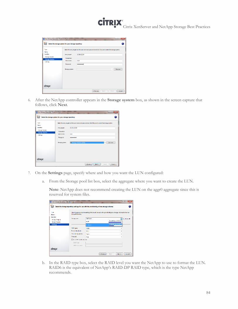
Citrix XenServer and NetApp Storage Best Practices
84
6. After the NetApp controller appears in the Storage system box, as shown in the screen capture that follows, click Next.
7. On the Settings page, specify where and how you want the LUN configured:
a. From the Storage pool list box, select the aggregate where you want to create the LUN.
Note: NetApp does not recommend creating the LUN on the aggr0 aggregate since this is reserved for system files.
b. In the RAID type box, select the RAID level you want the NetApp to use to format the LUN. RAID6 is the equivalent of NetApp’s RAID-DP RAID type, which is the type NetApp recommends.
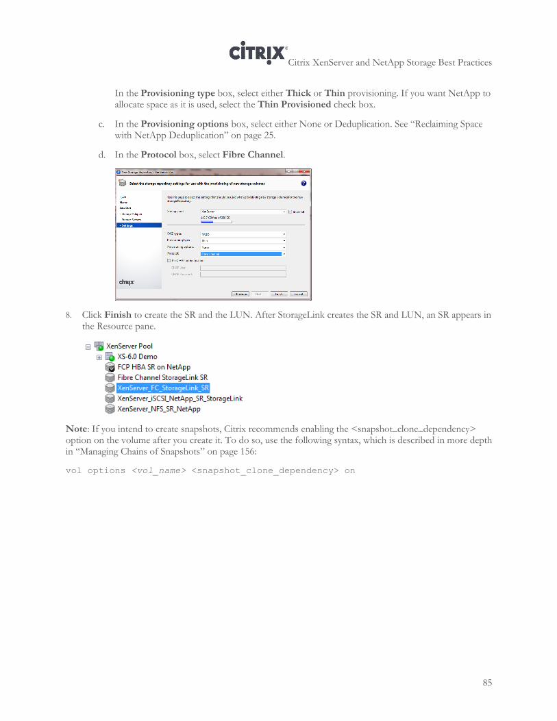
Citrix XenServer and NetApp Storage Best Practices
85
In the Provisioning type box, select either Thick or Thin provisioning. If you want NetApp to allocate space as it is used, select the Thin Provisioned check box.
c. In the Provisioning options box, select either None or Deduplication. See “Reclaiming Space with NetApp Deduplication” on page 25.
d. In the Protocol box, select Fibre Channel.
8. Click Finish to create the SR and the LUN. After StorageLink creates the SR and LUN, an SR appears in the Resource pane.
Note: If you intend to create snapshots, Citrix recommends enabling the <snapshot_clone_dependency> option on the volume after you create it. To do so, use the following syntax, which is described in more depth in “Managing Chains of Snapshots” on page 156:
vol options <vol_name> <snapshot_clone_dependency> on
Citrix XenServer and NetApp Storage Best Practices
86
Chapter 10: Configuring Storage with NetApp Virtual Storage Console for Citrix XenServer
This chapter contains information about NetApp Virtual Storage Console for Citrix XenServer, including the following:
Virtual Storage Console for XenServer overview
Storage Controller Management
Storage Repository Management
Overview
Virtual Storage Console for Citrix XenServer software is a single XenCenter Client plug-in that provides storage controller configuration, storage repository provisioning, and virtual machine (VM) cloning for Citrix XenServer environments running NetApp storage.
Virtual Storage Console for Citrix XenServer software offers fully orchestrated, XenServer administration-driven provisioning and cloning capabilities:
Storage controller discovery and configuration
NFS, iSCSI and Fibre Channel storage repository provisioning, deduplication and destruction
Resizing of existing NFS storage repository
Rapid VM cloning (in existing and new NFS-based storage repositories) for persistent desktops and virtual servers powered by NetApp FlexClone
Cloned VMs are instantly available in the Citrix XenDesktop for placement into catalogs
Role Based Access Control (RBAC) support
For installation and configuration detail, please see Virtual Storage Console Installation and Administration Guide. To download the Virtual Storage Console for Citrix XenServer, see the NetApp website.
Citrix XenServer and NetApp Storage Best Practices
87
Storage Controller Discovery and Configuration Overview VSC for Citrix XenServer provides the function of adding or discovering storage controllers and specifying credentials through the Tools > NetApp VSC > Discovery and Configuration option.
Before the VSC for Citrix XenServer can display and manage storage repositories, you must manually add or discover the storage controllers that provide the storage. As part of the discovery process, you must supply credentials, which are treated as global credentials and are applied to each controller that is discovered. If the credentials fail, you will need to edit the credentials individually.
Storage controller credentials are assigned based on the user name/password pair. This can be the root account or a custom account that uses role-based access control (RBAC). You cannot change the privileges associated with that user name/password pair in the Credentials section of the New Controller wizard. For more information regarding RBAC, see the XenCenter Help.
As part of the discovery process, the only types of storage controllers that are discovered are Administrator Vservers and physical storage controllers. If a physical storage controller has vFiler units configured, they will display in the Storage Controllers dialog box, in the Pass-Through Controllers section of the dialog box.
Discovering and Adding Storage Controllers
When discovering or adding storage controllers, you have the following options:
As part of the discovery process, you must supply credentials, which are treated as global credentials and are applied to each controller that is discovered. If the credentials fail, you will need to edit the credentials individually.
To discover or add a controller
1. Open XenCenter.
2. Select Tools > NetApp VSC > Discovery and Configuration.
3. Click Add a Controller. The New Controller wizard opens.
4. Select one of the following storage controller options and provide the appropriate input:
Add a single controller. Adds a single controller with a specified IP address or host name.
Discover controllers by IP range. Discovers a group of controllers within a specified range of IP addresses.
Discover controllers by net mask. Discovers a group of controllers at a specified IP address and by a net mask.
Note: When discovering a storage controller with multiple IP addresses and you plan to provision iSCSI storage repositories, the following recommendations will aid in facilitating the provisioning process:
• Only one IP address (either one vif or interface group for Data ONTAP operating in 7-mode, or one LIF for clustered Data ONTAP) should be designated for iSCSI provisioning. • The IP designated for iSCSI provisioning should not share a subnet with any of the other IP addresses.
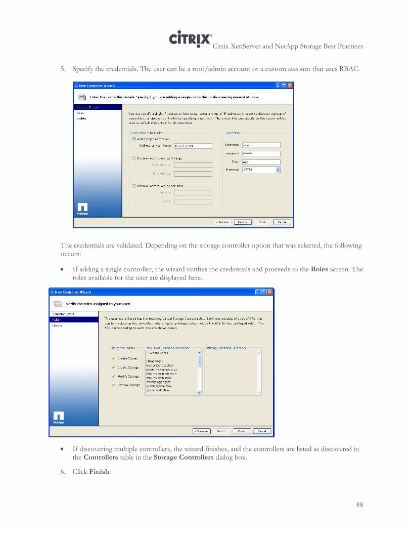
Citrix XenServer and NetApp Storage Best Practices
88
5. Specify the credentials. The user can be a root/admin account or a custom account that uses RBAC.
The credentials are validated. Depending on the storage controller option that was selected, the following occurs:
If adding a single controller, the wizard verifies the credentials and proceeds to the Roles screen. The roles available for the user are displayed here.
If discovering multiple controllers, the wizard finishes, and the controllers are listed as discovered in the Controllers table in the Storage Controllers dialog box.
6. Click Finish.
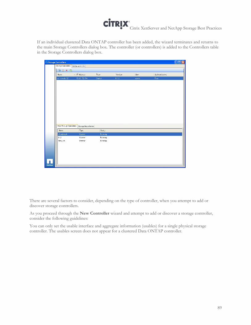
Citrix XenServer and NetApp Storage Best Practices
89
If an individual clustered Data ONTAP controller has been added, the wizard terminates and returns to the main Storage Controllers dialog box. The controller (or controllers) is added to the Controllers table in the Storage Controllers dialog box.
There are several factors to consider, depending on the type of controller, when you attempt to add or discover storage controllers.
As you proceed through the New Controller wizard and attempt to add or discover a storage controller, consider the following guidelines:
You can only set the usable interface and aggregate information (usables) for a single physical storage controller. The usables screen does not appear for a clustered Data ONTAP controller.
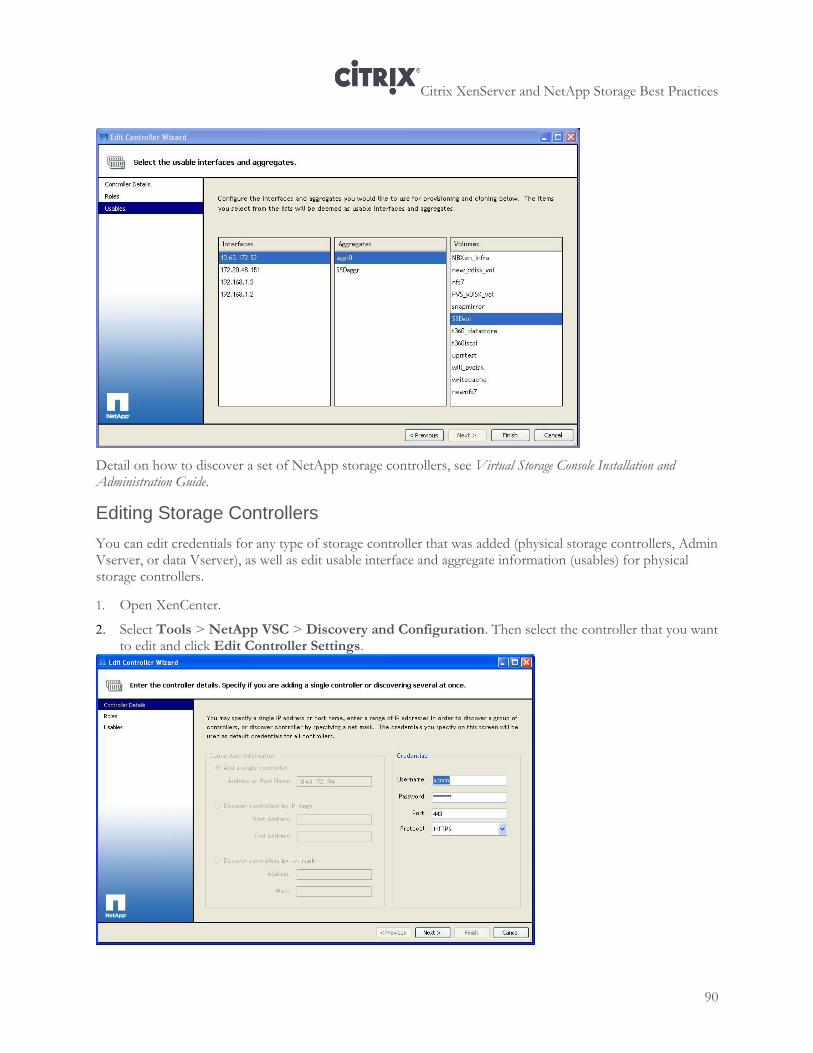
Citrix XenServer and NetApp Storage Best Practices
90
Detail on how to discover a set of NetApp storage controllers, see Virtual Storage Console Installation and Administration Guide.
Editing Storage Controllers
You can edit credentials for any type of storage controller that was added (physical storage controllers, Admin Vserver, or data Vserver), as well as edit usable interface and aggregate information (usables) for physical storage controllers.
1. Open XenCenter.
2. Select Tools > NetApp VSC > Discovery and Configuration. Then select the controller that you want to edit and click Edit Controller Settings.
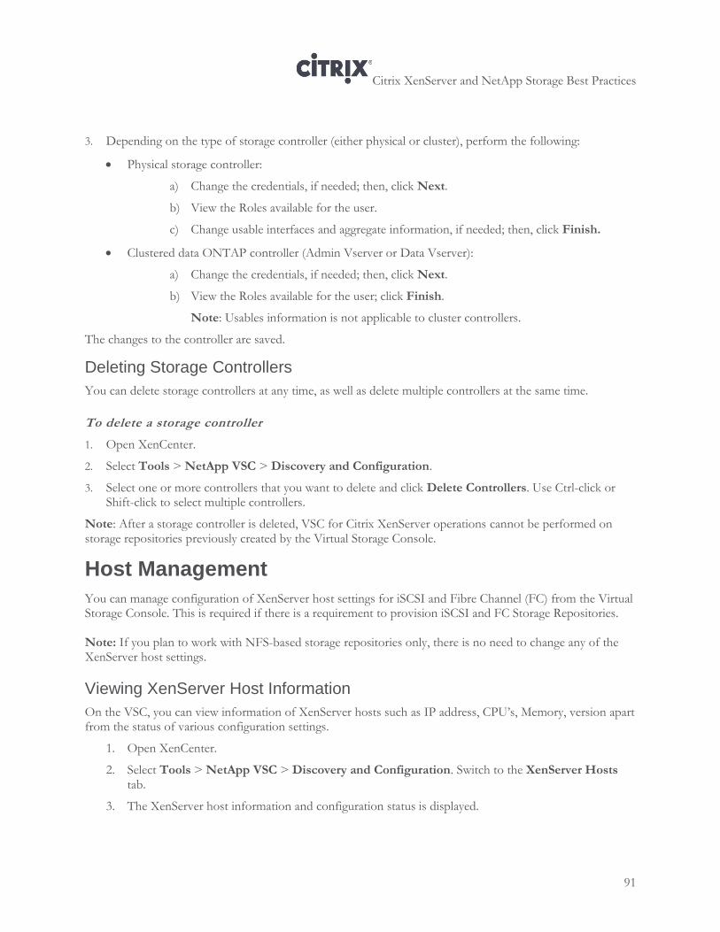
Citrix XenServer and NetApp Storage Best Practices
91
3. Depending on the type of storage controller (either physical or cluster), perform the following:
Physical storage controller:
a) Change the credentials, if needed; then, click Next.
b) View the Roles available for the user.
c) Change usable interfaces and aggregate information, if needed; then, click Finish.
Clustered data ONTAP controller (Admin Vserver or Data Vserver):
a) Change the credentials, if needed; then, click Next.
b) View the Roles available for the user; click Finish.
Note: Usables information is not applicable to cluster controllers.
The changes to the controller are saved.
Deleting Storage Controllers
You can delete storage controllers at any time, as well as delete multiple controllers at the same time.
To delete a storage controller
1. Open XenCenter.
2. Select Tools > NetApp VSC > Discovery and Configuration.
3. Select one or more controllers that you want to delete and click Delete Controllers. Use Ctrl-click or Shift-click to select multiple controllers.
Note: After a storage controller is deleted, VSC for Citrix XenServer operations cannot be performed on storage repositories previously created by the Virtual Storage Console.
Host Management
You can manage configuration of XenServer host settings for iSCSI and Fibre Channel (FC) from the Virtual Storage Console. This is required if there is a requirement to provision iSCSI and FC Storage Repositories. Note: If you plan to work with NFS-based storage repositories only, there is no need to change any of the XenServer host settings.
Viewing XenServer Host Information
On the VSC, you can view information of XenServer hosts such as IP address, CPU’s, Memory, version apart from the status of various configuration settings.
1. Open XenCenter.
2. Select Tools > NetApp VSC > Discovery and Configuration. Switch to the XenServer Hosts tab.
3. The XenServer host information and configuration status is displayed.
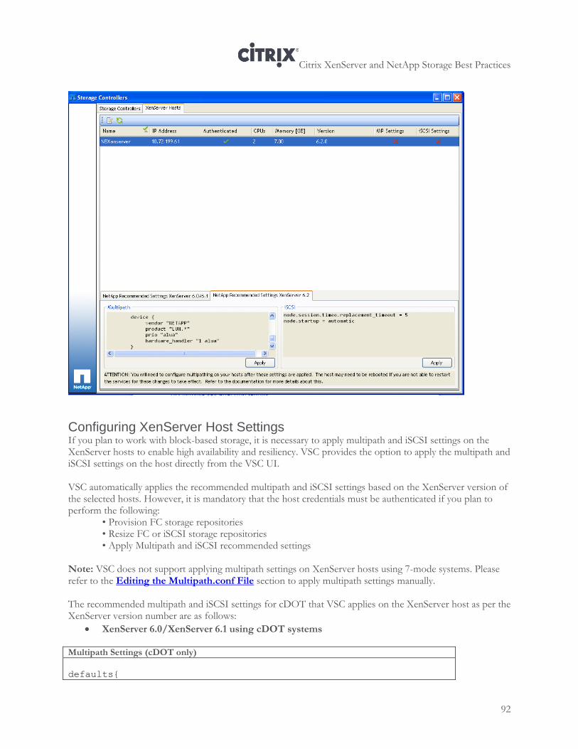
Citrix XenServer and NetApp Storage Best Practices
92
Configuring XenServer Host Settings If you plan to work with block-based storage, it is necessary to apply multipath and iSCSI settings on the XenServer hosts to enable high availability and resiliency. VSC provides the option to apply the multipath and iSCSI settings on the host directly from the VSC UI. VSC automatically applies the recommended multipath and iSCSI settings based on the XenServer version of the selected hosts. However, it is mandatory that the host credentials must be authenticated if you plan to perform the following:
• Provision FC storage repositories • Resize FC or iSCSI storage repositories • Apply Multipath and iSCSI recommended settings
Note: VSC does not support applying multipath settings on XenServer hosts using 7-mode systems. Please refer to the Editing the Multipath.conf File section to apply multipath settings manually. The recommended multipath and iSCSI settings for cDOT that VSC applies on the XenServer host as per the XenServer version number are as follows:
XenServer 6.0/XenServer 6.1 using cDOT systems
Multipath Settings (cDOT only)
defaults{
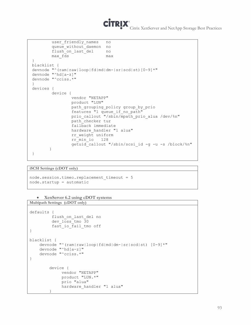
Citrix XenServer and NetApp Storage Best Practices
93
user_friendly_names no
queue_without_daemon no
flush_on_last_del no
max_fds max
}
blacklist {
devnode "^(ram|raw|loop|fd|md|dm-|sr|scd|st)[0-9]*"
devnode "^hd[a-z]"
devnode "^cciss.*"
}
devices {
device {
vendor "NETAPP"
product "LUN"
path_grouping_policy group_by_prio
features "1 queue_if_no_path"
prio_callout "/sbin/mpath_prio_alua /dev/%n"
path_checker tur
failback immediate
hardware_handler "1 alua"
rr_weight uniform
rr_min_io 128
getuid_callout "/sbin/scsi_id -g -u -s /block/%n"
}
}
iSCSI Settings (cDOT only)
node.session.timeo.replacement_timeout = 5
node.startup = automatic
XenServer 6.2 using cDOT systems Multipath Settings (cDOT only)
defaults {
flush_on_last_del no
dev_loss_tmo 30
fast_io_fail_tmo off
}
blacklist {
devnode "^(ram|raw|loop|fd|md|dm-|sr|scd|st) [0-9]*"
devnode "^hd[a-z]"
devnode "^cciss.*"
}
device {
vendor "NETAPP"
product "LUN.*"
prio "alua"
hardware_handler "1 alua"
}
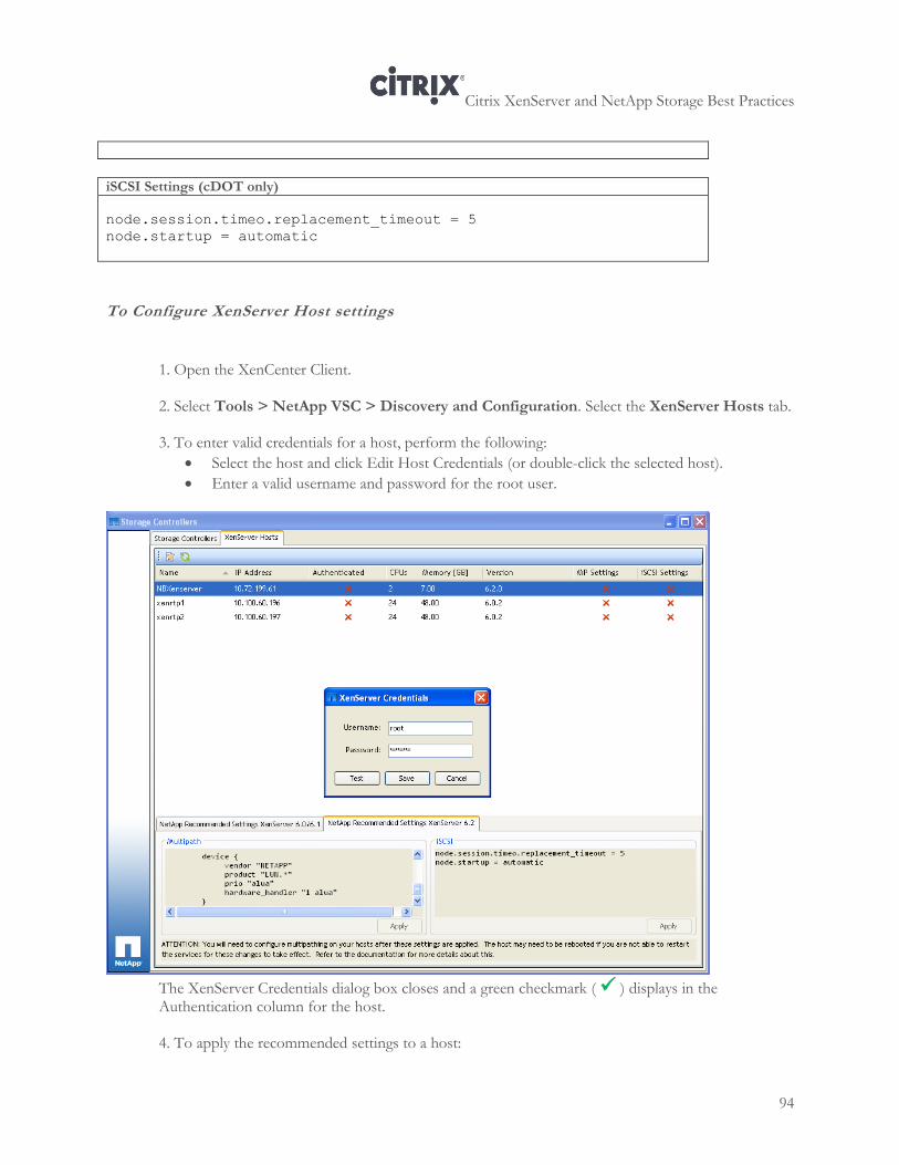
Citrix XenServer and NetApp Storage Best Practices
94
iSCSI Settings (cDOT only) node.session.timeo.replacement_timeout = 5
node.startup = automatic
To Configure XenServer Host settings
1. Open the XenCenter Client. 2. Select Tools > NetApp VSC > Discovery and Configuration. Select the XenServer Hosts tab. 3. To enter valid credentials for a host, perform the following:
Select the host and click Edit Host Credentials (or double-click the selected host).
Enter a valid username and password for the root user.
The XenServer Credentials dialog box closes and a green checkmark ( ) displays in the Authentication column for the host. 4. To apply the recommended settings to a host:
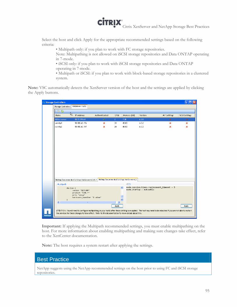
Citrix XenServer and NetApp Storage Best Practices
95
Select the host and click Apply for the appropriate recommended settings based on the following criteria:
• Multipath only: if you plan to work with FC storage repositories. Note: Multipathing is not allowed on iSCSI storage repositories and Data ONTAP operating in 7-mode. • iSCSI only: if you plan to work with iSCSI storage repositories and Data ONTAP operating in 7-mode. • Multipath or iSCSI: if you plan to work with block-based storage repositories in a clustered system.
Note: VSC automatically detects the XenServer version of the host and the settings are applied by clicking the Apply buttons.
Important: If applying the Multipath recommended settings, you must enable multipathing on the host. For more information about enabling multipathing and making sure changes take effect, refer to the XenCenter documentation. Note: The host requires a system restart after applying the settings.
Best Practice
NetApp suggests using the NetApp recommended settings on the host prior to using FC and iSCSI storage repositories.
Citrix XenServer and NetApp Storage Best Practices
96
Managing Storage Repositories Overview You can provision, resize, configure deduplication settings, and destroy storage repositories.
Provisioning Storage Repositories
You can create new storage repositories at the Pool and individual XenServer levels. At the Pool level, the storage repository will appear in all of the servers currently configured in that Pool. Before you can provision storage repositories, storage controllers must be discovered and configured.
About this task
Depending on the mode in which you are operating, storage repositories can be provisioned as follows -
When using Data ONTAP operating in 7-Mode, you can elect to provision on a physical storage controller or any vFiler units it may contain.
When using clustered Data ONTAP, you can either select the cluster and the data Vserver through which to provision the new storage repository, or select any Vservers which may have been added directly (for example, without an Admin Vserver) to the VSC for Citrix XenServer.
Note: There are certain limitations with direct-connect Vservers:
To provision storage repositories on direct-connect Vservers, a new role and a new user with the required privileges to provision must be created. The default vsadmin role assigned to Vservers does not contain the volume efficiency commands needed by for provisioning and cloning. For more information on performing this operation, see the System Manager documentation available from the NetApp Support site.
Storage repositories creation is not supported on striped aggregates. When you add a direct- connect Vserver, any striped aggregates associated with it appear as available. Provisioning on those striped aggregates will fail.
Also, when provisioning block-based (FC and iSCSI) storage repositories, the process might take a longer time (as compared to NFS-based storage repositories) due to having to re-scan Host Bus Adapters (HBAs) on the XenServers. Note: When managing storage repositories in clustered systems, if Load Sharing Mirror (LSM) on the root volume of a clustered system is enabled, it is recommended that you either perform an incremental update so the volume is available for VSC or disable LSM altogether. For detailed information, refer to the NetApp Technical Report TR-4015: SnapMirror Configuration and Best Practices Guide for Data ONTAP 8.1 Operating in Cluster-Mode.
To provision storage repositories
1. Open XenCenter.
2. Right-click a pool or XenServer and select NetApp VSC > Provision Storage Repository. The Storage Repository Provisioning wizard opens.
3. Select the target storage controller where the storage repository will be provisioned.
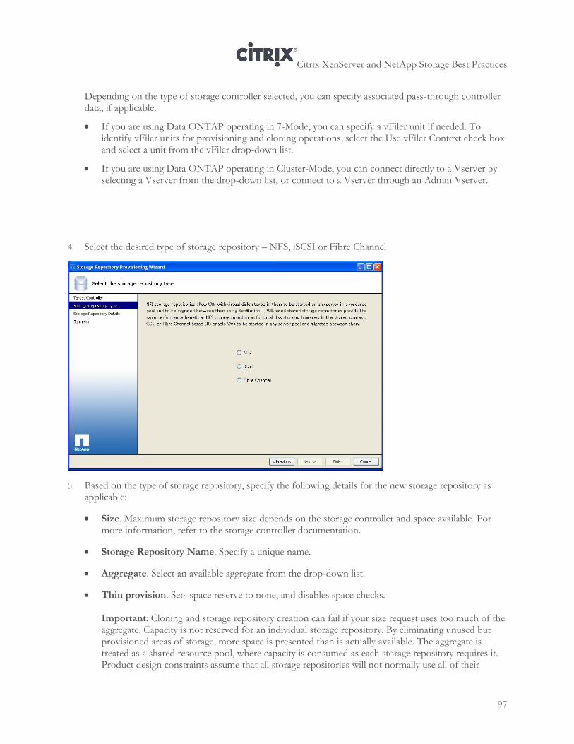
Citrix XenServer and NetApp Storage Best Practices
97
Depending on the type of storage controller selected, you can specify associated pass-through controller data, if applicable.
If you are using Data ONTAP operating in 7-Mode, you can specify a vFiler unit if needed. To identify vFiler units for provisioning and cloning operations, select the Use vFiler Context check box and select a unit from the vFiler drop-down list.
If you are using Data ONTAP operating in Cluster-Mode, you can connect directly to a Vserver by selecting a Vserver from the drop-down list, or connect to a Vserver through an Admin Vserver.
4. Select the desired type of storage repository – NFS, iSCSI or Fibre Channel
5. Based on the type of storage repository, specify the following details for the new storage repository as applicable:
Size. Maximum storage repository size depends on the storage controller and space available. For more information, refer to the storage controller documentation.
Storage Repository Name. Specify a unique name.
Aggregate. Select an available aggregate from the drop-down list.
Thin provision. Sets space reserve to none, and disables space checks.
Important: Cloning and storage repository creation can fail if your size request uses too much of the aggregate. Capacity is not reserved for an individual storage repository. By eliminating unused but provisioned areas of storage, more space is presented than is actually available. The aggregate is treated as a shared resource pool, where capacity is consumed as each storage repository requires it. Product design constraints assume that all storage repositories will not normally use all of their
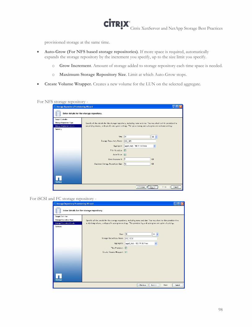
Citrix XenServer and NetApp Storage Best Practices
98
provisioned storage at the same time.
Auto-Grow (For NFS based storage repositories). If more space is required, automatically expands the storage repository by the increment you specify, up to the size limit you specify.
o Grow Increment. Amount of storage added to storage repository each time space is needed.
o Maximum Storage Repository Size. Limit at which Auto-Grow stops.
Create Volume Wrapper. Creates a new volume for the LUN on the selected aggregate.
For NFS storage repository -
For iSCSI and FC storage repository -
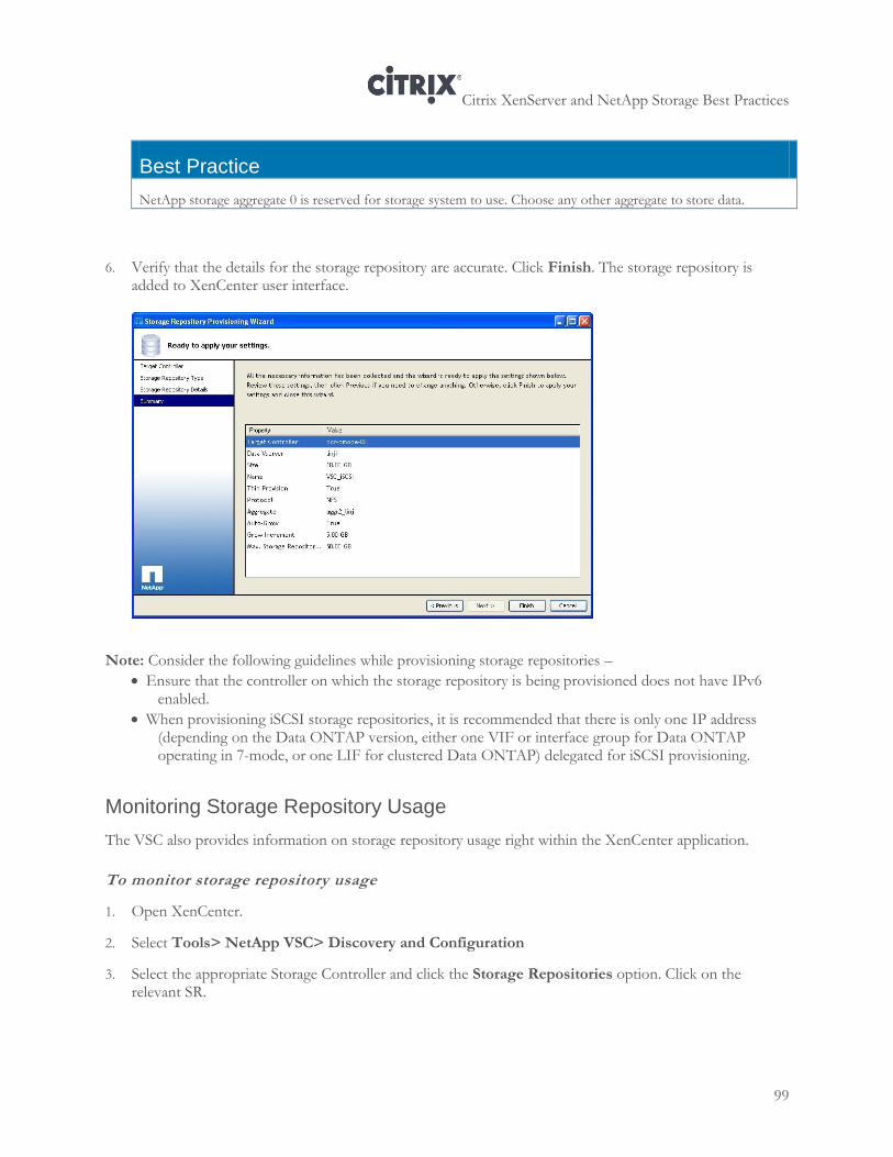
Citrix XenServer and NetApp Storage Best Practices
99
Best Practice
NetApp storage aggregate 0 is reserved for storage system to use. Choose any other aggregate to store data.
6. Verify that the details for the storage repository are accurate. Click Finish. The storage repository is added to XenCenter user interface.
Note: Consider the following guidelines while provisioning storage repositories –
Ensure that the controller on which the storage repository is being provisioned does not have IPv6 enabled.
When provisioning iSCSI storage repositories, it is recommended that there is only one IP address (depending on the Data ONTAP version, either one VIF or interface group for Data ONTAP operating in 7-mode, or one LIF for clustered Data ONTAP) delegated for iSCSI provisioning.
Monitoring Storage Repository Usage
The VSC also provides information on storage repository usage right within the XenCenter application.
To monitor storage repository usage
1. Open XenCenter.
2. Select Tools> NetApp VSC> Discovery and Configuration
3. Select the appropriate Storage Controller and click the Storage Repositories option. Click on the relevant SR.
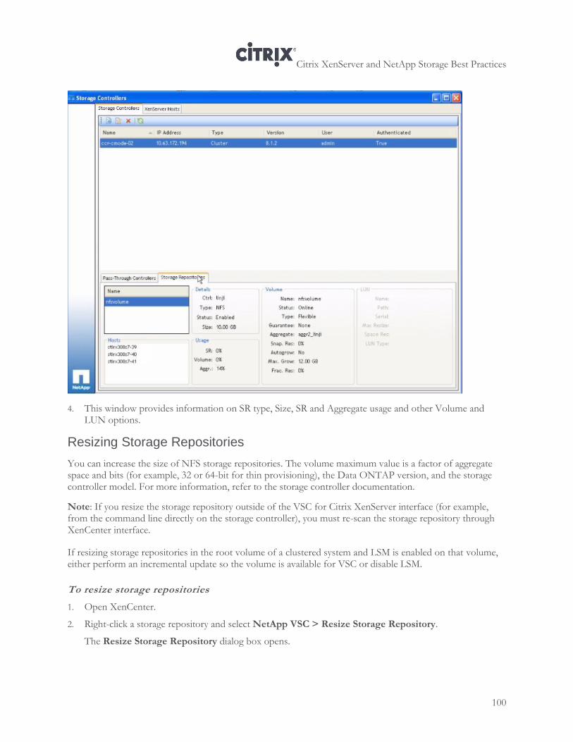
Citrix XenServer and NetApp Storage Best Practices
100
4. This window provides information on SR type, Size, SR and Aggregate usage and other Volume and LUN options.
Resizing Storage Repositories
You can increase the size of NFS storage repositories. The volume maximum value is a factor of aggregate space and bits (for example, 32 or 64-bit for thin provisioning), the Data ONTAP version, and the storage controller model. For more information, refer to the storage controller documentation.
Note: If you resize the storage repository outside of the VSC for Citrix XenServer interface (for example, from the command line directly on the storage controller), you must re-scan the storage repository through XenCenter interface.
If resizing storage repositories in the root volume of a clustered system and LSM is enabled on that volume, either perform an incremental update so the volume is available for VSC or disable LSM.
To resize storage repositories
1. Open XenCenter.
2. Right-click a storage repository and select NetApp VSC > Resize Storage Repository.
The Resize Storage Repository dialog box opens.
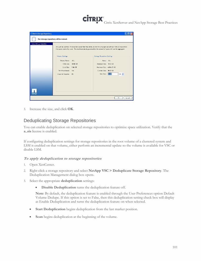
Citrix XenServer and NetApp Storage Best Practices
101
3. Increase the size, and click OK.
Deduplicating Storage Repositories
You can enable deduplication on selected storage repositories to optimize space utilization. Verify that the a_sis license is enabled.
If configuring deduplication settings for storage repositories in the root volume of a clustered system and LSM is enabled on that volume, either perform an incremental update so the volume is available for VSC or disable LSM.
To apply deduplication to storage repositories
1. Open XenCenter.
2. Right-click a storage repository and select NetApp VSC > Deduplicate Storage Repository. The Deduplication Management dialog box opens.
3. Select the appropriate deduplication settings:
Disable Deduplication turns the deduplication feature off.
Note: By default, the deduplication feature is enabled through the User Preferences option Default Volume Dedupe. If this option is set to False, then this deduplication setting check box will display as Enable Deduplication and turns the deduplication feature on when selected.
Start Deduplication begins deduplication from the last marker position.
Scan begins deduplication at the beginning of the volume.
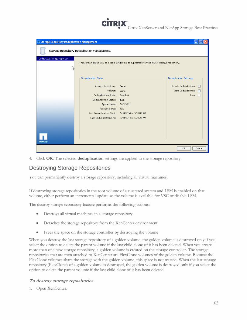
Citrix XenServer and NetApp Storage Best Practices
102
4. Click OK. The selected deduplication settings are applied to the storage repository.
Destroying Storage Repositories
You can permanently destroy a storage repository, including all virtual machines.
If destroying storage repositories in the root volume of a clustered system and LSM is enabled on that volume, either perform an incremental update so the volume is available for VSC or disable LSM.
The destroy storage repository feature performs the following actions:
Destroys all virtual machines in a storage repository
Detaches the storage repository from the XenCenter environment
Frees the space on the storage controller by destroying the volume
When you destroy the last storage repository of a golden volume, the golden volume is destroyed only if you select the option to delete the parent volume if the last child clone of it has been deleted. When you create more than one new storage repository, a golden volume is created on the storage controller. The storage repositories that are then attached to XenCenter are FlexClone volumes of the golden volume. Because the FlexClone volumes share the storage with the golden volume, this space is not wasted. When the last storage repository (FlexClone) of a golden volume is destroyed, the golden volume is destroyed only if you select the option to delete the parent volume if the last child clone of it has been deleted.
To destroy storage repositories
1. Open XenCenter.
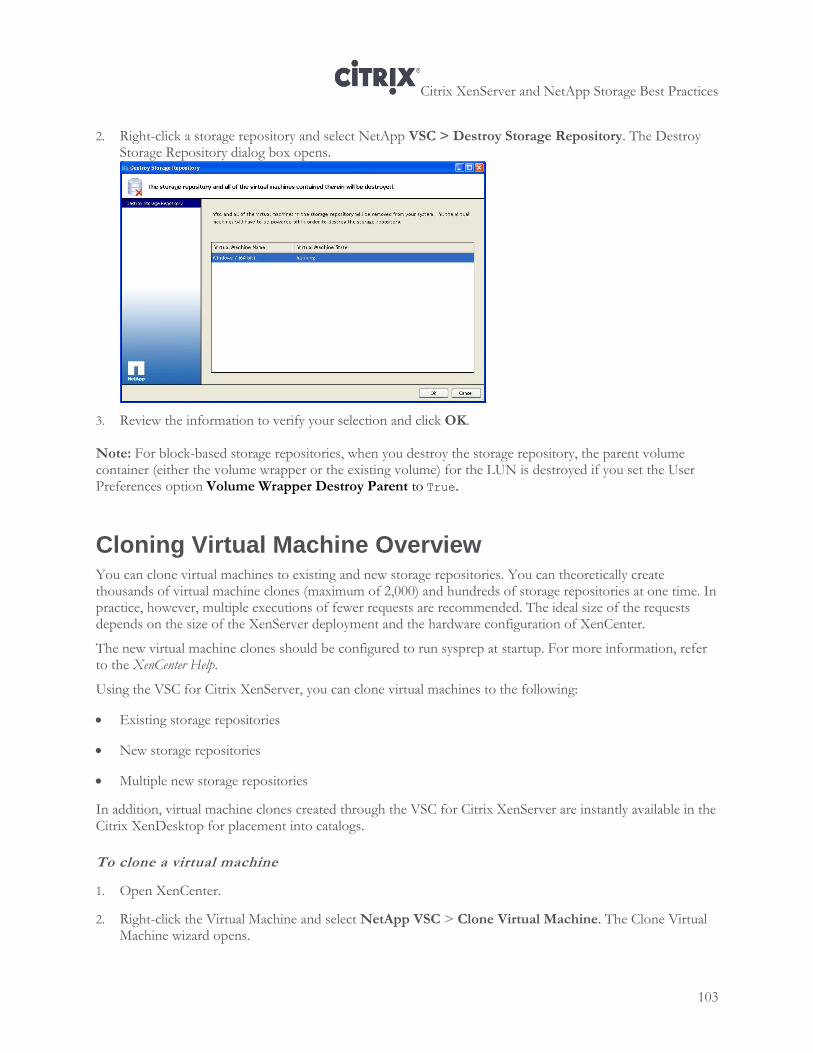
Citrix XenServer and NetApp Storage Best Practices
103
2. Right-click a storage repository and select NetApp VSC > Destroy Storage Repository. The Destroy Storage Repository dialog box opens.
3. Review the information to verify your selection and click OK.
Note: For block-based storage repositories, when you destroy the storage repository, the parent volume container (either the volume wrapper or the existing volume) for the LUN is destroyed if you set the User Preferences option Volume Wrapper Destroy Parent to True.
Cloning Virtual Machine Overview You can clone virtual machines to existing and new storage repositories. You can theoretically create thousands of virtual machine clones (maximum of 2,000) and hundreds of storage repositories at one time. In practice, however, multiple executions of fewer requests are recommended. The ideal size of the requests depends on the size of the XenServer deployment and the hardware configuration of XenCenter.
The new virtual machine clones should be configured to run sysprep at startup. For more information, refer to the XenCenter Help.
Using the VSC for Citrix XenServer, you can clone virtual machines to the following:
Existing storage repositories
New storage repositories
Multiple new storage repositories
In addition, virtual machine clones created through the VSC for Citrix XenServer are instantly available in the Citrix XenDesktop for placement into catalogs.
To clone a virtual machine
1. Open XenCenter.
2. Right-click the Virtual Machine and select NetApp VSC > Clone Virtual Machine. The Clone Virtual Machine wizard opens.
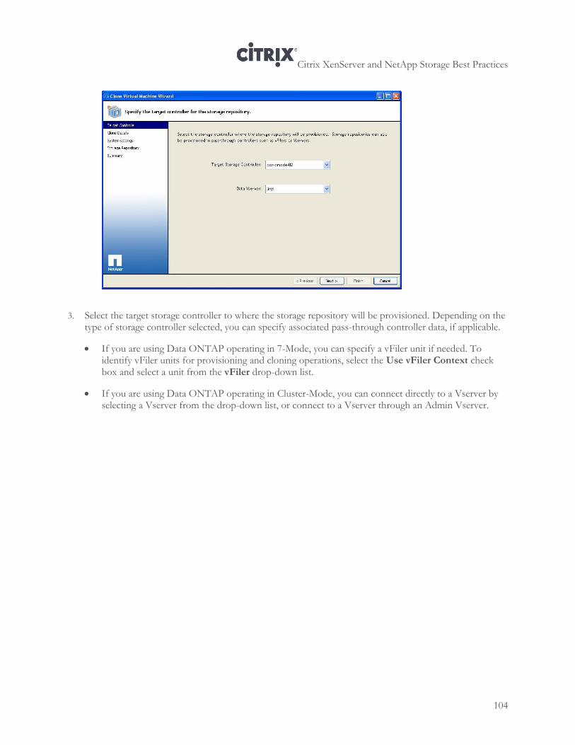
Citrix XenServer and NetApp Storage Best Practices
104
3. Select the target storage controller to where the storage repository will be provisioned. Depending on the type of storage controller selected, you can specify associated pass-through controller data, if applicable.
If you are using Data ONTAP operating in 7-Mode, you can specify a vFiler unit if needed. To identify vFiler units for provisioning and cloning operations, select the Use vFiler Context check box and select a unit from the vFiler drop-down list.
If you are using Data ONTAP operating in Cluster-Mode, you can connect directly to a Vserver by selecting a Vserver from the drop-down list, or connect to a Vserver through an Admin Vserver.
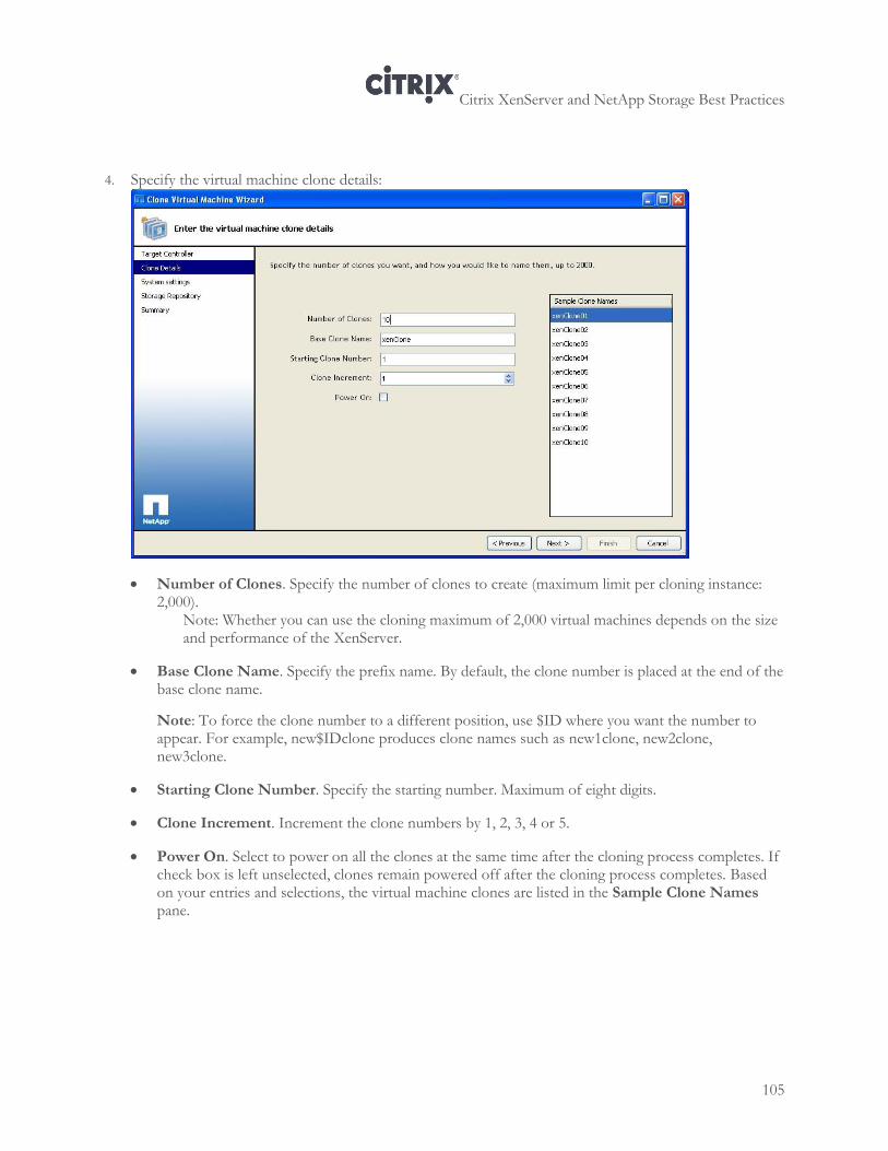
Citrix XenServer and NetApp Storage Best Practices
105
4. Specify the virtual machine clone details:
Number of Clones. Specify the number of clones to create (maximum limit per cloning instance: 2,000).
Note: Whether you can use the cloning maximum of 2,000 virtual machines depends on the size and performance of the XenServer.
Base Clone Name. Specify the prefix name. By default, the clone number is placed at the end of the base clone name.
Note: To force the clone number to a different position, use $ID where you want the number to appear. For example, new$IDclone produces clone names such as new1clone, new2clone, new3clone.
Starting Clone Number. Specify the starting number. Maximum of eight digits.
Clone Increment. Increment the clone numbers by 1, 2, 3, 4 or 5.
Power On. Select to power on all the clones at the same time after the cloning process completes. If check box is left unselected, clones remain powered off after the cloning process completes. Based on your entries and selections, the virtual machine clones are listed in the Sample Clone Names pane.
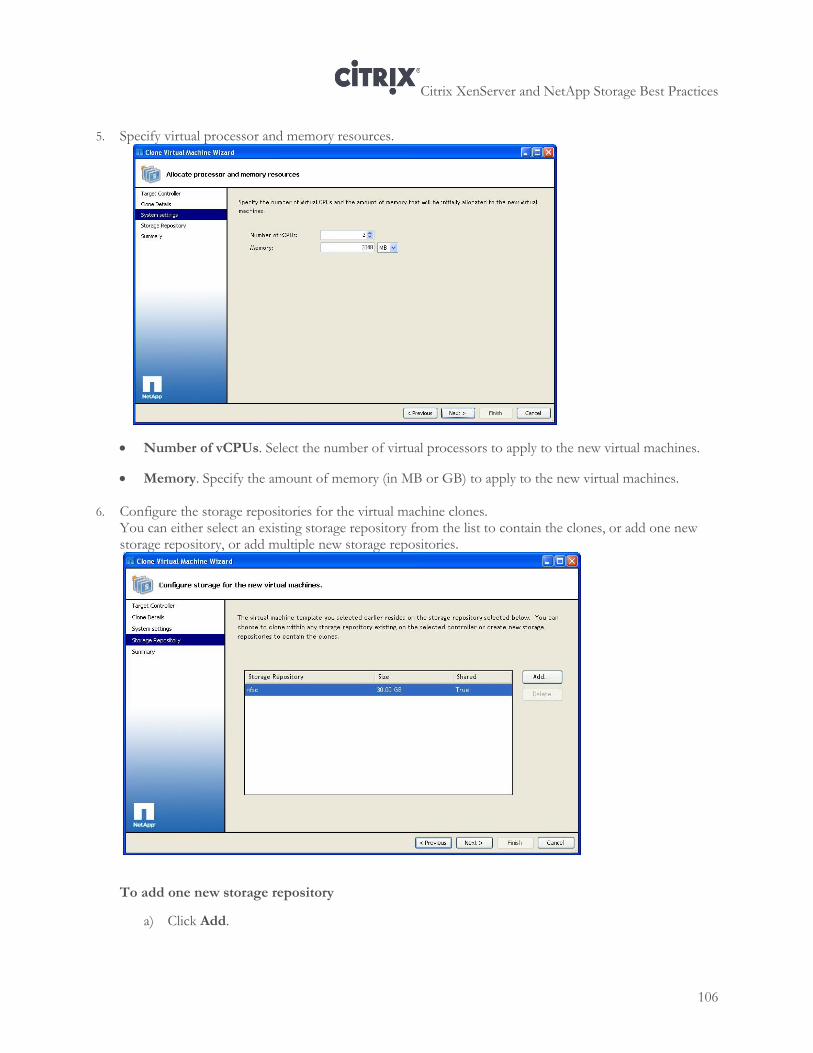
Citrix XenServer and NetApp Storage Best Practices
106
5. Specify virtual processor and memory resources.
Number of vCPUs. Select the number of virtual processors to apply to the new virtual machines.
Memory. Specify the amount of memory (in MB or GB) to apply to the new virtual machines.
6. Configure the storage repositories for the virtual machine clones. You can either select an existing storage repository from the list to contain the clones, or add one new storage repository, or add multiple new storage repositories.
To add one new storage repository
a) Click Add.
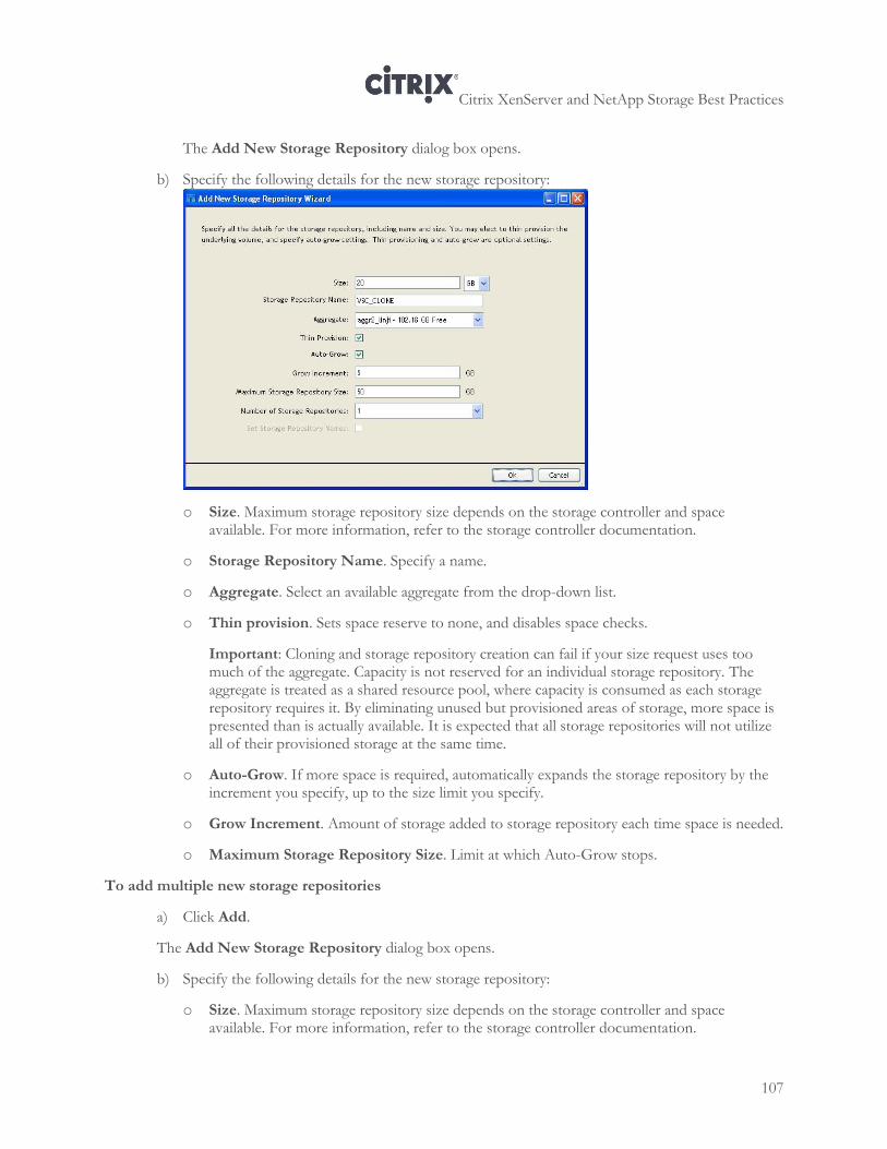
Citrix XenServer and NetApp Storage Best Practices
107
The Add New Storage Repository dialog box opens.
b) Specify the following details for the new storage repository:
o Size. Maximum storage repository size depends on the storage controller and space available. For more information, refer to the storage controller documentation.
o Storage Repository Name. Specify a name.
o Aggregate. Select an available aggregate from the drop-down list.
o Thin provision. Sets space reserve to none, and disables space checks.
Important: Cloning and storage repository creation can fail if your size request uses too much of the aggregate. Capacity is not reserved for an individual storage repository. The aggregate is treated as a shared resource pool, where capacity is consumed as each storage repository requires it. By eliminating unused but provisioned areas of storage, more space is presented than is actually available. It is expected that all storage repositories will not utilize all of their provisioned storage at the same time.
o Auto-Grow. If more space is required, automatically expands the storage repository by the increment you specify, up to the size limit you specify.
o Grow Increment. Amount of storage added to storage repository each time space is needed.
o Maximum Storage Repository Size. Limit at which Auto-Grow stops.
To add multiple new storage repositories
a) Click Add.
The Add New Storage Repository dialog box opens.
b) Specify the following details for the new storage repository:
o Size. Maximum storage repository size depends on the storage controller and space available. For more information, refer to the storage controller documentation.
Citrix XenServer and NetApp Storage Best Practices
108
o Number of Storage Repositories. Select the number of new storage repositories. The number of new storage repositories must divide evenly into the number of total new clones.
Note: The number of storage repositories that can be added is limited by the number of FlexClone volumes that can be created on the storage platform and Data ONTAP version. As a result, because of these limitations and depending on your environment, if you attempt to add a large number (for example, 1,000) of storage repositories, the operation might fail. For more information, refer to the storage controller documentation.
o Golden Volume Name. Specify a name.
o Aggregate. Select an available aggregate from the drop-down list.
o Thin provision. Sets space reserve to none, and disables space checks.
Important: Cloning and storage repository creation can fail if your size request uses too much of the aggregate. Capacity is not reserved for an individual storage repository. By eliminating unused but provisioned areas of storage, more space is presented than is actually available. The aggregate is treated as a shared resource pool, where capacity is consumed as each storage repository requires it. Product design constraints assume that all storage repositories will not normally use all of their provisioned storage at the same time.
o Auto-Grow. If more space is required, automatically expands the storage repository by the increment you specify, up to the size limit you specify.
o Grow Increment. Amount of storage added to storage repository each time space is needed.
o Maximum Storage Repository Size. Limit at which Auto-Grow stops.
o Set Storage Repository Names. Enables modification of default storage repositories name. 7. Review the summary page and click Finish to proceed.
Citrix XenServer and NetApp Storage Best Practices
109
Chapter 11: Creating Redundancy for Storage Traffic
This chapter provides information about the following:
Configuring NIC bonding and multipathing
Creating Multiple Storage Management Interfaces for iSCSI Multipathing
Configuring Fibre Channel Multipathing
For information about configuring ALUA, see “Chapter 12: Configuring a High Availability Pair of Controllers (ALUA.”
Overview
XenServer supports NIC bonding, and it supports active/active multipathing for iSCSI and Fibre Channel protocols. This section provides information about configuring multipathing and NIC bonding and includes the following topics:
An overview of NIC bonding
When to select NIC bonding or multipathing
Understanding XenServer multipathing and multipath handler support
This section also contains background information that may not be necessary for some audiences. However, this information is given to provide a common baseline of information and avoid pitfalls that result from common misconceptions.
Best Practice
For proper redundancy, configure NIC bonding or multipathing with at least two physical Ethernet switches.
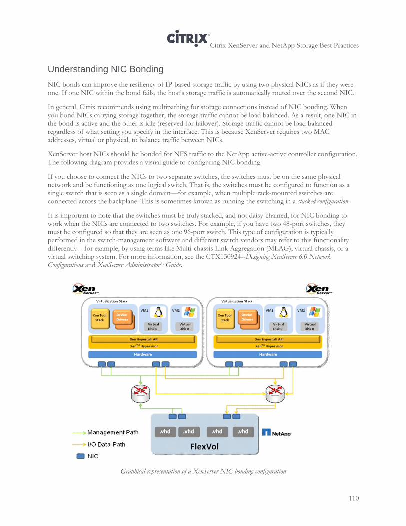
Citrix XenServer and NetApp Storage Best Practices
110
Understanding NIC Bonding
NIC bonds can improve the resiliency of IP-based storage traffic by using two physical NICs as if they were one. If one NIC within the bond fails, the host's storage traffic is automatically routed over the second NIC.
In general, Citrix recommends using multipathing for storage connections instead of NIC bonding. When you bond NICs carrying storage together, the storage traffic cannot be load balanced. As a result, one NIC in the bond is active and the other is idle (reserved for failover). Storage traffic cannot be load balanced regardless of what setting you specify in the interface. This is because XenServer requires two MAC addresses, virtual or physical, to balance traffic between NICs.
XenServer host NICs should be bonded for NFS traffic to the NetApp active-active controller configuration. The following diagram provides a visual guide to configuring NIC bonding.
If you choose to connect the NICs to two separate switches, the switches must be on the same physical network and be functioning as one logical switch. That is, the switches must be configured to function as a single switch that is seen as a single domain—for example, when multiple rack-mounted switches are connected across the backplane. This is sometimes known as running the switching in a stacked configuration.
It is important to note that the switches must be truly stacked, and not daisy-chained, for NIC bonding to work when the NICs are connected to two switches. For example, if you have two 48-port switches, they must be configured so that they are seen as one 96-port switch. This type of configuration is typically performed in the switch-management software and different switch vendors may refer to this functionality differently – for example, by using terms like Multi-chassis Link Aggregation (MLAG), virtual chassis, or a virtual switching system. For more information, see the CTX130924--Designing XenServer 6.0 Network Configurations and XenServer Administrator’s Guide.
Graphical representation of a XenServer NIC bonding configuration
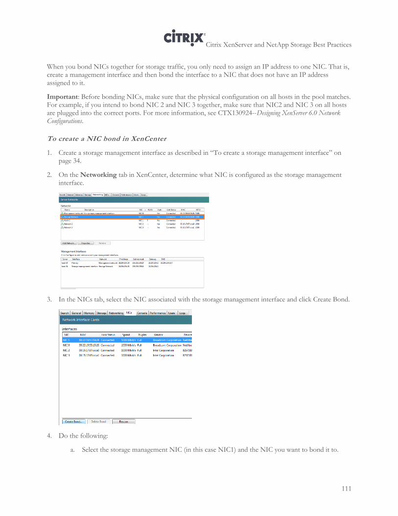
Citrix XenServer and NetApp Storage Best Practices
111
When you bond NICs together for storage traffic, you only need to assign an IP address to one NIC. That is, create a management interface and then bond the interface to a NIC that does not have an IP address assigned to it.
Important: Before bonding NICs, make sure that the physical configuration on all hosts in the pool matches. For example, if you intend to bond NIC 2 and NIC 3 together, make sure that NIC2 and NIC 3 on all hosts are plugged into the correct ports. For more information, see CTX130924--Designing XenServer 6.0 Network Configurations.
To create a NIC bond in XenCenter
1. Create a storage management interface as described in “To create a storage management interface” on page 34.
2. On the Networking tab in XenCenter, determine what NIC is configured as the storage management interface.
3. In the NICs tab, select the NIC associated with the storage management interface and click Create Bond.
4. Do the following:
a. Select the storage management NIC (in this case NIC1) and the NIC you want to bond it to.
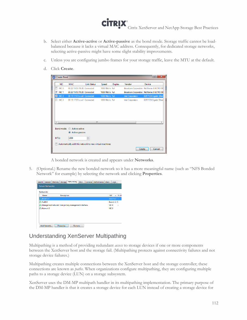
Citrix XenServer and NetApp Storage Best Practices
112
b. Select either Active-active or Active-passive as the bond mode. Storage traffic cannot be load-balanced because it lacks a virtual MAC address. Consequently, for dedicated storage networks, selecting active-passive might have some slight stability improvements.
c. Unless you are configuring jumbo frames for your storage traffic, leave the MTU at the default.
d. Click Create.
A bonded network is created and appears under Networks.
5. (Optional.) Rename the new bonded network so it has a more meaningful name (such as “NFS Bonded Network” for example) by selecting the network and clicking Properties.
Understanding XenServer Multipathing
Multipathing is a method of providing redundant access to storage devices if one or more components between the XenServer host and the storage fail. (Multipathing protects against connectivity failures and not storage device failures.)
Multipathing creates multiple connections between the XenServer host and the storage controller; these connections are known as paths. When organizations configure multipathing, they are configuring multiple paths to a storage device (LUN) on a storage subsystem.
XenServer uses the DM-MP multipath handler in its multipathing implementation. The primary purpose of the DM-MP handler is that it creates a storage device for each LUN instead of creating a storage device for
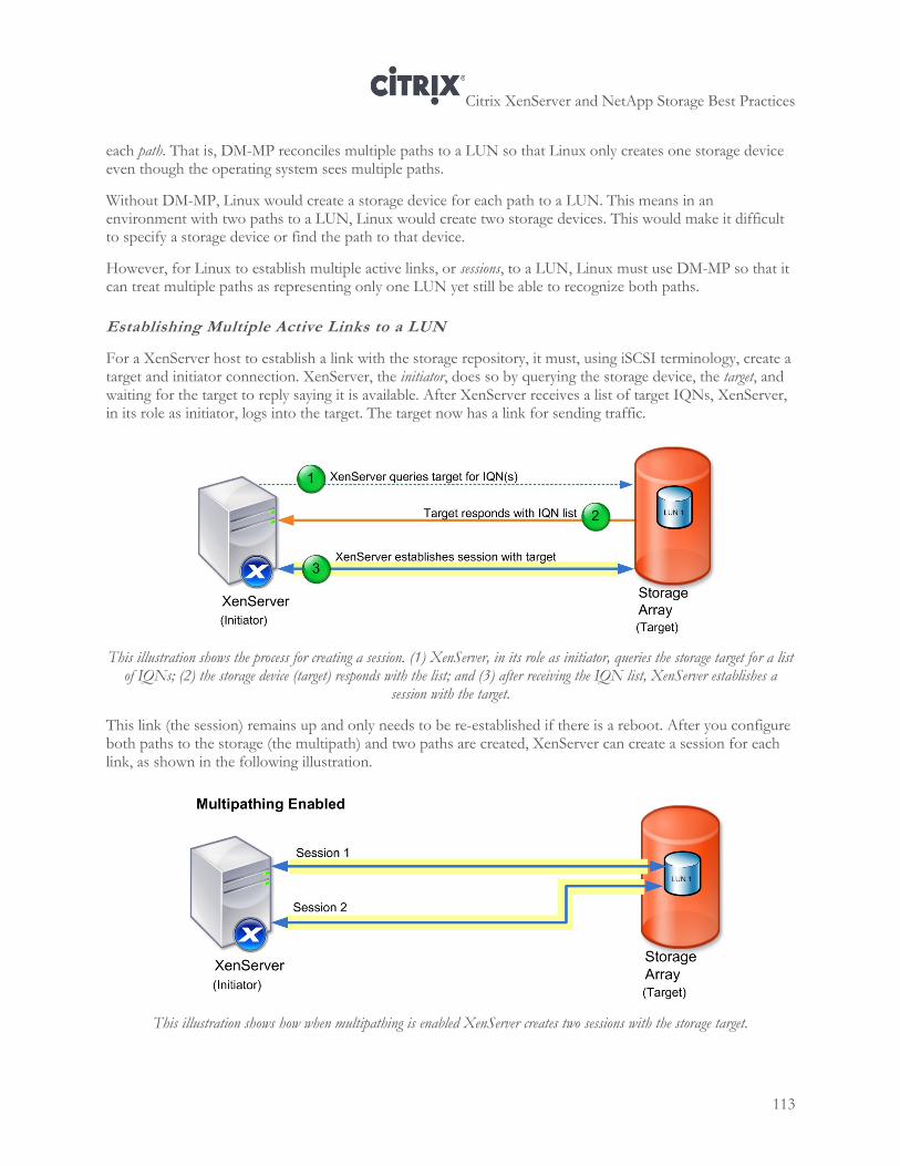
Citrix XenServer and NetApp Storage Best Practices
113
each path. That is, DM-MP reconciles multiple paths to a LUN so that Linux only creates one storage device even though the operating system sees multiple paths.
Without DM-MP, Linux would create a storage device for each path to a LUN. This means in an environment with two paths to a LUN, Linux would create two storage devices. This would make it difficult to specify a storage device or find the path to that device.
However, for Linux to establish multiple active links, or sessions, to a LUN, Linux must use DM-MP so that it can treat multiple paths as representing only one LUN yet still be able to recognize both paths.
Establishing Multiple Active Links to a LUN
For a XenServer host to establish a link with the storage repository, it must, using iSCSI terminology, create a target and initiator connection. XenServer, the initiator, does so by querying the storage device, the target, and waiting for the target to reply saying it is available. After XenServer receives a list of target IQNs, XenServer, in its role as initiator, logs into the target. The target now has a link for sending traffic.
This illustration shows the process for creating a session. (1) XenServer, in its role as initiator, queries the storage target for a list of IQNs; (2) the storage device (target) responds with the list; and (3) after receiving the IQN list, XenServer establishes a
session with the target.
This link (the session) remains up and only needs to be re-established if there is a reboot. After you configure both paths to the storage (the multipath) and two paths are created, XenServer can create a session for each link, as shown in the following illustration.
This illustration shows how when multipathing is enabled XenServer creates two sessions with the storage target.
Citrix XenServer and NetApp Storage Best Practices
114
The multipath handler uses target IQNs to determine if the storage devices discovered on the target are different LUNs or different paths. The handler makes this determination by querying the storage target. The target replies with the IQN, which includes the LUN serial number. (Ideally, regardless of the number of paths connecting to a LUN, the serial number in the IQN is always the same.)
For Fibre Channel, the process is similar. However, the multipath handler uses target WWPNs.
The multipath handler checks IQNs for matching serial numbers to determine how many paths are associated with each LUN. When the serial numbers in the IQNs match, the handler assumes that the IQNs are associated with the same LUN and therefore must represent different paths to that LUN.
When you create the storage repository and multipathing is enabled (specifically, when you create the Physical Block Device (PBD)), XenServer includes a multihome parameter that configures XenServer to expect a multihomed device. (The term multihome refers to computer or, in this case, a storage device that has multiple IP addresses connected to a network.)
If XenServer is not aware the storage device is multihomed (because multipathing was not enabled before the PBD/storage repository was created), XenServer can only create one session (or path) to the storage.
For iSCSI storage, it is better to configure multipathing first; however, if you created the storage repository first, you can put the host into maintenance mode and then configure multipathing. (For Fibre Channel, Citrix strongly recommends configuring multipathing and enabling the multipathing check box in XenCenter before creating the storage repository.)
With all types of SANs, it is best to plan and design your storage and networking configuration before implementation, determine you want multipathing, and configure it before putting the pool into production. Configuring multipathing after the pool is live results in a service interruption: configuring multipathing affects all VMs connected to the storage repository.
Important points to note about multipathing:
1. Multipathing is a “pool-level” feature and if you enable multipathing on one host, multipathing must be
enabled on all hosts in the pool. It is possible to enable multipathing for only specific storage in a pool by
following instructions for excluding storage using the blacklist in the multipath.conf file, as described in
CTX118791—Multipathing Overview for XenServer 5.0.
2. Multipathing is enabled at the host level. However, although hosts must have the same (shared) storage
repositories on each host in the pool, hosts can have more than one SR. This means that if you enable
multipathing it applies to all SRs in the pool and assumes multiple paths. If multiple paths are not present
for a specific LUN, XenServer can still connect with multipathing enabled. However, there might be a
slight performance degradation.
With NetApp arrays, dynamic multipathing uses a round-robin mode load balancing algorithm for the connection to the owning controller. Multipathing can be enabled via XenCenter or on the command line. However, before attempting to enable multipathing, verify that multiple targets are available on your storage server.
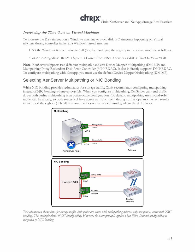
Citrix XenServer and NetApp Storage Best Practices
115
Increasing the Time Outs on Virtual Machines
To increase the Disk timeout on a Windows machine to avoid disk I/O timeouts happening on Virtual machine during controller faults, at a Windows virtual machine
1. Set the Windows timeout value to 190 (Sec) by modifying the registry in the virtual machine as follows: Start->run->regedit->HKLM->System->CurrentControlSet->Services->disk->TimeOutValue=190
Note: XenServer supports two different multipath handlers: Device Mapper Multipathing (DM-MP) and Multipathing Proxy Redundant Disk Array Controller (MPP RDAC). It also indirectly supports DMP RDAC. To configure multipathing with NetApp, you must use the default Device Mapper Multipathing (DM-MP).
Selecting XenServer Multipathing or NIC Bonding
While NIC bonding provides redundancy for storage traffic, Citrix recommends configuring multipathing instead of NIC bonding whenever possible. When you configure multipathing, XenServer can send traffic down both paths: multipathing is an active-active configuration. (By default, multipathing uses round-robin mode load balancing, so both routes will have active traffic on them during normal operation, which results in increased throughput.) The illustration that follows provides a visual guide to the differences.
This illustration shows how, for storage traffic, both paths are active with multipathing whereas only one path is active with NIC bonding. This example shows iSCSI multipathing. However, the same principle applies when Fibre Channel multipathing is compared to NIC bonding.
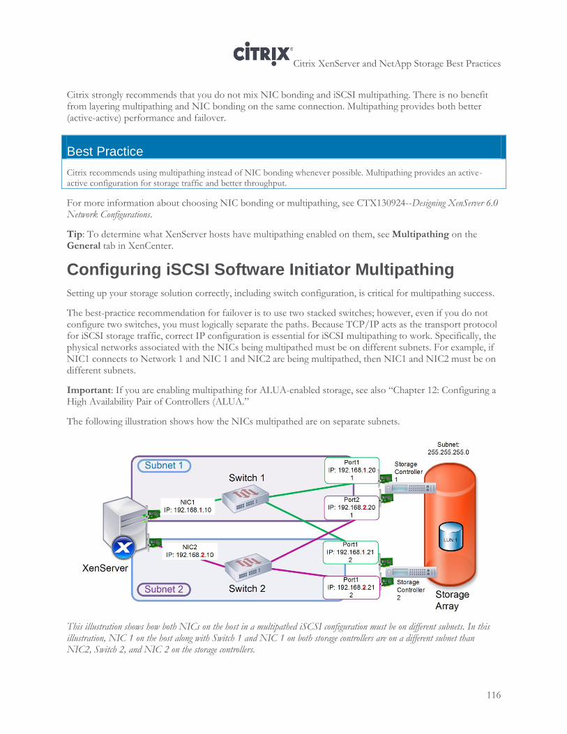
Citrix XenServer and NetApp Storage Best Practices
116
Citrix strongly recommends that you do not mix NIC bonding and iSCSI multipathing. There is no benefit from layering multipathing and NIC bonding on the same connection. Multipathing provides both better (active-active) performance and failover.
Best Practice
Citrix recommends using multipathing instead of NIC bonding whenever possible. Multipathing provides an active-active configuration for storage traffic and better throughput.
For more information about choosing NIC bonding or multipathing, see CTX130924--Designing XenServer 6.0 Network Configurations.
Tip: To determine what XenServer hosts have multipathing enabled on them, see Multipathing on the General tab in XenCenter.
Configuring iSCSI Software Initiator Multipathing
Setting up your storage solution correctly, including switch configuration, is critical for multipathing success.
The best-practice recommendation for failover is to use two stacked switches; however, even if you do not configure two switches, you must logically separate the paths. Because TCP/IP acts as the transport protocol for iSCSI storage traffic, correct IP configuration is essential for iSCSI multipathing to work. Specifically, the physical networks associated with the NICs being multipathed must be on different subnets. For example, if NIC1 connects to Network 1 and NIC 1 and NIC2 are being multipathed, then NIC1 and NIC2 must be on different subnets.
Important: If you are enabling multipathing for ALUA-enabled storage, see also “Chapter 12: Configuring a High Availability Pair of Controllers (ALUA.”
The following illustration shows how the NICs multipathed are on separate subnets.
This illustration shows how both NICs on the host in a multipathed iSCSI configuration must be on different subnets. In this illustration, NIC 1 on the host along with Switch 1 and NIC 1 on both storage controllers are on a different subnet than NIC2, Switch 2, and NIC 2 on the storage controllers.
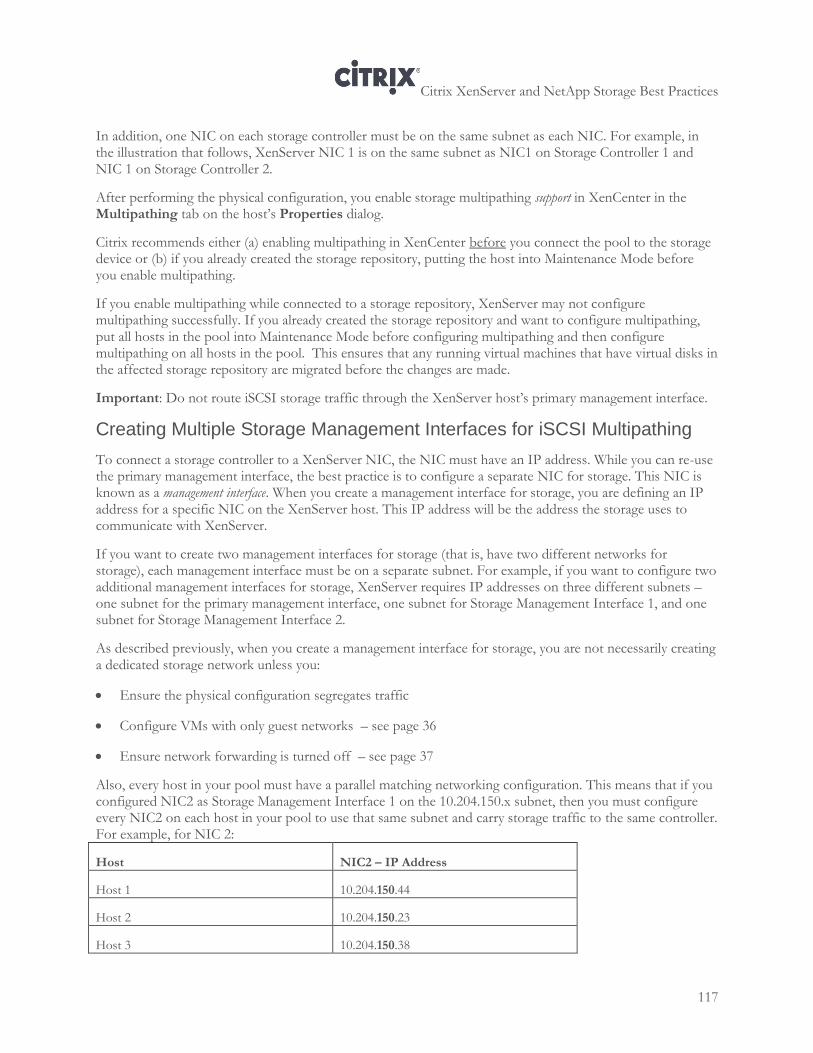
Citrix XenServer and NetApp Storage Best Practices
117
In addition, one NIC on each storage controller must be on the same subnet as each NIC. For example, in the illustration that follows, XenServer NIC 1 is on the same subnet as NIC1 on Storage Controller 1 and NIC 1 on Storage Controller 2.
After performing the physical configuration, you enable storage multipathing support in XenCenter in the Multipathing tab on the host’s Properties dialog.
Citrix recommends either (a) enabling multipathing in XenCenter before you connect the pool to the storage device or (b) if you already created the storage repository, putting the host into Maintenance Mode before you enable multipathing.
If you enable multipathing while connected to a storage repository, XenServer may not configure multipathing successfully. If you already created the storage repository and want to configure multipathing, put all hosts in the pool into Maintenance Mode before configuring multipathing and then configure multipathing on all hosts in the pool. This ensures that any running virtual machines that have virtual disks in the affected storage repository are migrated before the changes are made.
Important: Do not route iSCSI storage traffic through the XenServer host’s primary management interface.
Creating Multiple Storage Management Interfaces for iSCSI Multipathing
To connect a storage controller to a XenServer NIC, the NIC must have an IP address. While you can re-use the primary management interface, the best practice is to configure a separate NIC for storage. This NIC is known as a management interface. When you create a management interface for storage, you are defining an IP address for a specific NIC on the XenServer host. This IP address will be the address the storage uses to communicate with XenServer.
If you want to create two management interfaces for storage (that is, have two different networks for storage), each management interface must be on a separate subnet. For example, if you want to configure two additional management interfaces for storage, XenServer requires IP addresses on three different subnets – one subnet for the primary management interface, one subnet for Storage Management Interface 1, and one subnet for Storage Management Interface 2.
As described previously, when you create a management interface for storage, you are not necessarily creating a dedicated storage network unless you:
Ensure the physical configuration segregates traffic
Configure VMs with only guest networks – see page 36
Ensure network forwarding is turned off – see page 37
Also, every host in your pool must have a parallel matching networking configuration. This means that if you configured NIC2 as Storage Management Interface 1 on the 10.204.150.x subnet, then you must configure every NIC2 on each host in your pool to use that same subnet and carry storage traffic to the same controller. For example, for NIC 2:
Host NIC2 – IP Address
Host 1 10.204.150.44
Host 2 10.204.150.23
Host 3 10.204.150.38
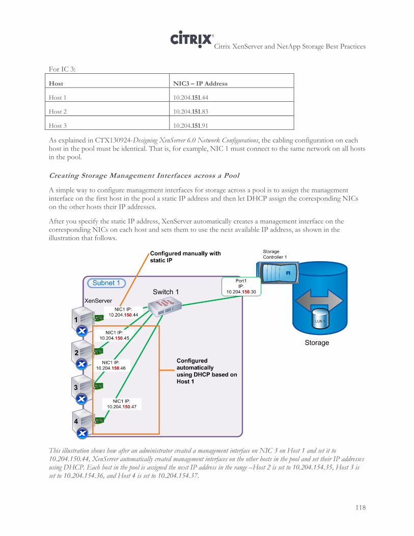
Citrix XenServer and NetApp Storage Best Practices
118
For IC 3:
Host NIC3 – IP Address
Host 1 10.204.151.44
Host 2 10.204.151.83
Host 3 10.204.151.91
As explained in CTX130924-Designing XenServer 6.0 Network Configurations, the cabling configuration on each host in the pool must be identical. That is, for example, NIC 1 must connect to the same network on all hosts in the pool.
Creating Storage Management Interfaces across a Pool
A simple way to configure management interfaces for storage across a pool is to assign the management interface on the first host in the pool a static IP address and then let DHCP assign the corresponding NICs on the other hosts their IP addresses.
After you specify the static IP address, XenServer automatically creates a management interface on the corresponding NICs on each host and sets them to use the next available IP address, as shown in the illustration that follows.
This illustration shows how after an administrator created a management interface on NIC 3 on Host 1 and set it to 10.204.150.44, XenServer automatically created management interfaces on the other hosts in the pool and set their IP addresses using DHCP. Each host in the pool is assigned the next IP address in the range –Host 2 is set to 10.204.154.35, Host 3 is set to 10.204.154.36, and Host 4 is set to 10.204.154.37.
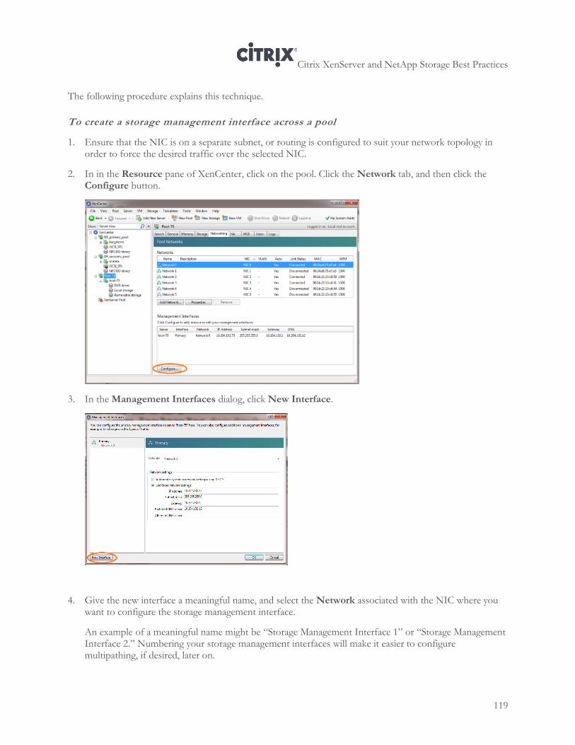
Citrix XenServer and NetApp Storage Best Practices
119
The following procedure explains this technique.
To create a storage management interface across a pool
1. Ensure that the NIC is on a separate subnet, or routing is configured to suit your network topology in order to force the desired traffic over the selected NIC.
2. In in the Resource pane of XenCenter, click on the pool. Click the Network tab, and then click the Configure button.
3. In the Management Interfaces dialog, click New Interface.
4. Give the new interface a meaningful name, and select the Network associated with the NIC where you want to configure the storage management interface.
An example of a meaningful name might be “Storage Management Interface 1” or “Storage Management Interface 2.” Numbering your storage management interfaces will make it easier to configure multipathing, if desired, later on.
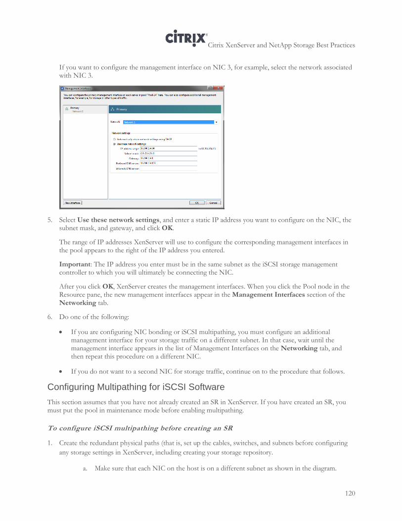
Citrix XenServer and NetApp Storage Best Practices
120
If you want to configure the management interface on NIC 3, for example, select the network associated with NIC 3.
5. Select Use these network settings, and enter a static IP address you want to configure on the NIC, the subnet mask, and gateway, and click OK.
The range of IP addresses XenServer will use to configure the corresponding management interfaces in the pool appears to the right of the IP address you entered.
Important: The IP address you enter must be in the same subnet as the iSCSI storage management controller to which you will ultimately be connecting the NIC.
After you click OK, XenServer creates the management interfaces. When you click the Pool node in the Resource pane, the new management interfaces appear in the Management Interfaces section of the Networking tab.
6. Do one of the following:
If you are configuring NIC bonding or iSCSI multipathing, you must configure an additional management interface for your storage traffic on a different subnet. In that case, wait until the management interface appears in the list of Management Interfaces on the Networking tab, and then repeat this procedure on a different NIC.
If you do not want to a second NIC for storage traffic, continue on to the procedure that follows.
Configuring Multipathing for iSCSI Software
This section assumes that you have not already created an SR in XenServer. If you have created an SR, you must put the pool in maintenance mode before enabling multipathing.
To configure iSCSI multipathing before creating an SR
1. Create the redundant physical paths (that is, set up the cables, switches, and subnets before configuring
any storage settings in XenServer, including creating your storage repository.
a. Make sure that each NIC on the host is on a different subnet as shown in the diagram.
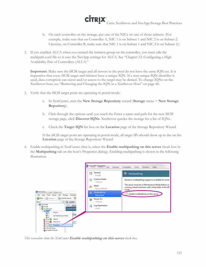
Citrix XenServer and NetApp Storage Best Practices
121
b. On each controller on the storage, put one of the NICs on one of those subnets. (For
example, make sure that on Controller A, NIC 1 is on Subnet 1 and NIC 2 is on Subnet 2.
Likewise, on Controller B, make sure that NIC 1 is on Subnet 1 and NIC 2 is on Subnet 2.)
2. If you enabled ALUA when you created the initiator group on the controller, you must edit the
multipath.conf file so it uses the NetApp settings for ALUA. See “Chapter 12: Configuring a High
Availability Pair of Controllers (ALUA.”
Important: Make sure the iSCSI target and all servers in the pool do not have the same IQN set. It is imperative that every iSCSI target and initiator have a unique IQN. If a non-unique IQN identifier is used, data corruption can occur and/or access to the target may be denied. To change IQNs on the XenServer host, see “Retrieving and Changing the IQN in a XenServer Host” on page 46.
3. Verify that the iSCSI target ports are operating in portal mode:
a. In XenCenter, start the New Storage Repository wizard (Storage menu > New Storage
Repository).
b. Click through the options until you reach the Enter a name and path for the new iSCSI
storage page, click Discover IQNs. XenServer queries the storage for a list of IQNs.
c. Check the Target IQN list box on the Location page of the Storage Repository Wizard.
If the iSCSI target ports are operating in portal mode, all target IPs should show up in the on the Location page of the Storage Repository Wizard.
4. Enable multipathing in XenCenter (that is, select the Enable multipathing on this server check box in
the Multipathing tab on the host’s Properties dialog). Enabling multipathing is shown in the following
illustration:
This screenshot show the XenCenter Enable multipathing on this server check box.
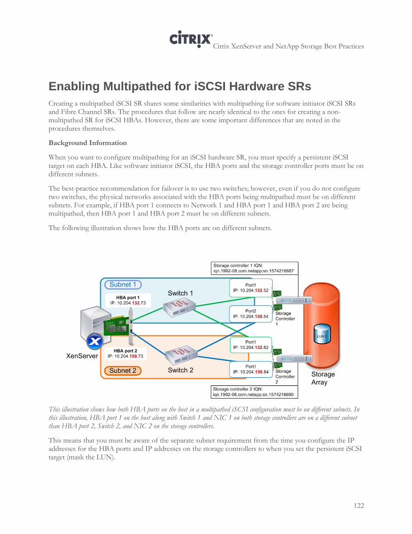
Citrix XenServer and NetApp Storage Best Practices
122
Enabling Multipathed for iSCSI Hardware SRs
Creating a multipathed iSCSI SR shares some similarities with multipathing for software initiator iSCSI SRs and Fibre Channel SRs. The procedures that follow are nearly identical to the ones for creating a non-multipathed SR for iSCSI HBAs. However, there are some important differences that are noted in the procedures themselves.
Background Information
When you want to configure multipathing for an iSCSI hardware SR, you must specify a persistent iSCSI target on each HBA. Like software initiator iSCSI, the HBA ports and the storage controller ports must be on different subnets.
The best-practice recommendation for failover is to use two switches; however, even if you do not configure two switches, the physical networks associated with the HBA ports being multipathed must be on different subnets. For example, if HBA port 1 connects to Network 1 and HBA port 1 and HBA port 2 are being multipathed, then HBA port 1 and HBA port 2 must be on different subnets.
The following illustration shows how the HBA ports are on different subnets.
This illustration shows how both HBA ports on the host in a multipathed iSCSI configuration must be on different subnets. In this illustration, HBA port 1 on the host along with Switch 1 and NIC 1 on both storage controllers are on a different subnet than HBA port 2, Switch 2, and NIC 2 on the storage controllers.
This means that you must be aware of the separate subnet requirement from the time you configure the IP addresses for the HBA ports and IP addresses on the storage controllers to when you set the persistent iSCSI target (mask the LUN).
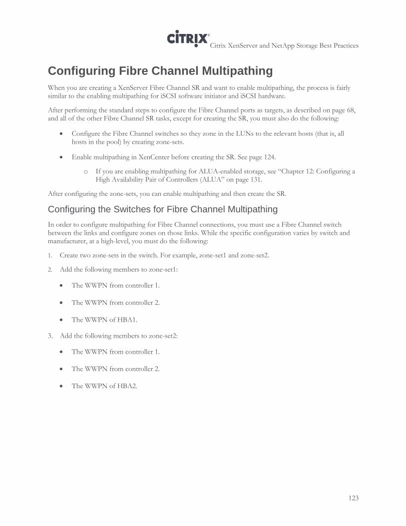
Citrix XenServer and NetApp Storage Best Practices
123
Configuring Fibre Channel Multipathing
When you are creating a XenServer Fibre Channel SR and want to enable multipathing, the process is fairly similar to the enabling multipathing for iSCSI software initiator and iSCSI hardware.
After performing the standard steps to configure the Fibre Channel ports as targets, as described on page 68, and all of the other Fibre Channel SR tasks, except for creating the SR, you must also do the following:
Configure the Fibre Channel switches so they zone in the LUNs to the relevant hosts (that is, all hosts in the pool) by creating zone-sets.
Enable multipathing in XenCenter before creating the SR. See page 124.
o If you are enabling multipathing for ALUA-enabled storage, see “Chapter 12: Configuring a High Availability Pair of Controllers (ALUA” on page 131.
After configuring the zone-sets, you can enable multipathing and then create the SR.
Configuring the Switches for Fibre Channel Multipathing
In order to configure multipathing for Fibre Channel connections, you must use a Fibre Channel switch between the links and configure zones on those links. While the specific configuration varies by switch and manufacturer, at a high-level, you must do the following:
1. Create two zone-sets in the switch. For example, zone-set1 and zone-set2.
2. Add the following members to zone-set1:
The WWPN from controller 1.
The WWPN from controller 2.
The WWPN of HBA1.
3. Add the following members to zone-set2:
The WWPN from controller 1.
The WWPN from controller 2.
The WWPN of HBA2.
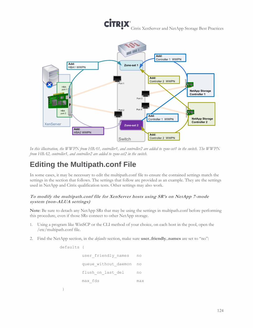
Citrix XenServer and NetApp Storage Best Practices
124
In this illustration, the WWPN from HBA1, controller1, and controller2 are added to zone-set1 in the switch. The WWPN from HBA2, controller1, and controller2 are added to zone-set2 in the switch.
Editing the Multipath.conf File
In some cases, it may be necessary to edit the multipath.conf file to ensure the contained settings match the settings in the section that follows. The settings that follow are provided as an example. They are the settings used in NetApp and Citrix qualification tests. Other settings may also work.
To modify the multipath.conf file for XenServer hosts using SR’s on NetApp 7-mode system (non-ALUA settings)
Note: Be sure to detach any NetApp SRs that may be using the settings in multipath.conf before performing this procedure, even if those SRs connect to other NetApp storage.
1. Using a program like WinSCP or the CLI method of your choice, on each host in the pool, open the /etc/multipath.conf file.
2. Find the NetApp section, in the defaults section, make sure user_friendly_names are set to “no”:
defaults {
user_friendly_names no
queue_without_daemon no
flush_on_last_del no
max_fds max
}
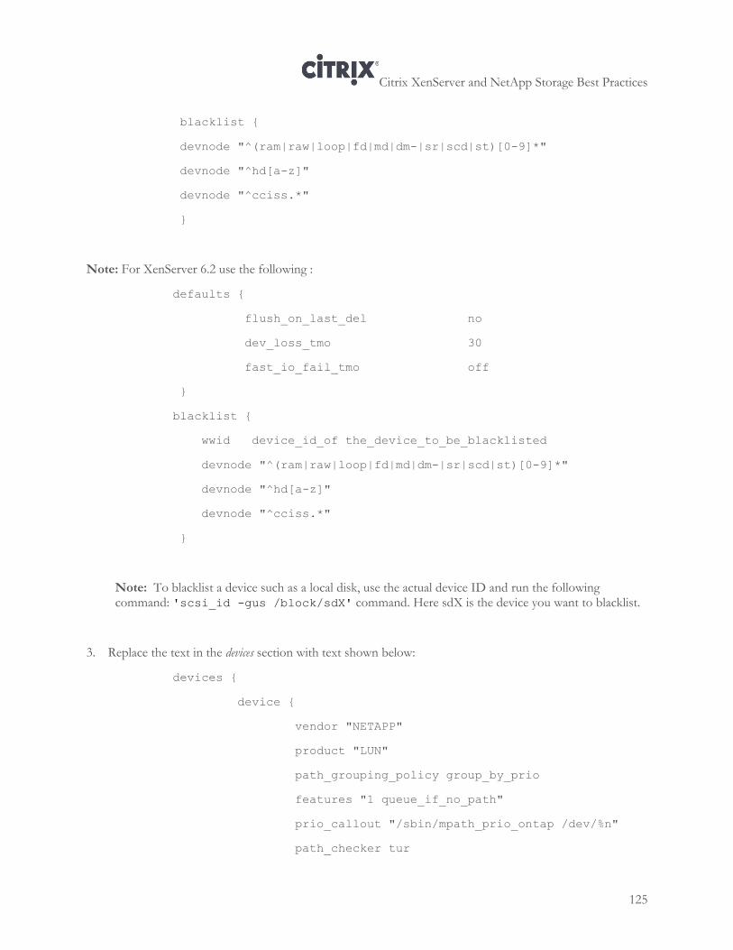
Citrix XenServer and NetApp Storage Best Practices
125
blacklist {
devnode "^(ram|raw|loop|fd|md|dm-|sr|scd|st)[0-9]*"
devnode "^hd[a-z]"
devnode "^cciss.*"
}
Note: For XenServer 6.2 use the following :
defaults {
flush_on_last_del no
dev_loss_tmo 30
fast_io_fail_tmo off
}
blacklist {
wwid device_id_of the_device_to_be_blacklisted
devnode "^(ram|raw|loop|fd|md|dm-|sr|scd|st)[0-9]*"
devnode "^hd[a-z]"
devnode "^cciss.*"
}
Note: To blacklist a device such as a local disk, use the actual device ID and run the following command: 'scsi_id -gus /block/sdX' command. Here sdX is the device you want to blacklist.
3. Replace the text in the devices section with text shown below:
devices {
device {
vendor "NETAPP"
product "LUN"
path_grouping_policy group_by_prio
features "1 queue_if_no_path"
prio_callout "/sbin/mpath_prio_ontap /dev/%n"
path_checker tur
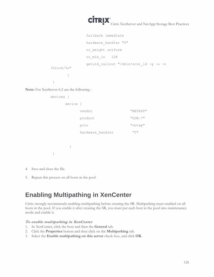
Citrix XenServer and NetApp Storage Best Practices
126
failback immediate
hardware_handler "0"
rr_weight uniform
rr_min_io 128
getuid_callout "/sbin/scsi_id -g -u -s
/block/%n"
}
}
Note: For XenServer 6.2 use the following :
devices {
device {
vendor "NETAPP"
product "LUN.*"
prio "ontap"
hardware_handler "0"
}
}
4. Save and close the file.
5. Repeat this process on all hosts in the pool.
Enabling Multipathing in XenCenter
Citrix strongly recommends enabling multipathing before creating the SR. Multipathing must enabled on all hosts in the pool. If you enable it after creating the SR, you must put each host in the pool into maintenance mode and enable it.
To enable multipathing in XenCenter
1. In XenCenter, click the host and then the General tab.
2. Click the Properties button and then click on the Multipathing tab.
3. Select the Enable multipathing on this server check box, and click OK.
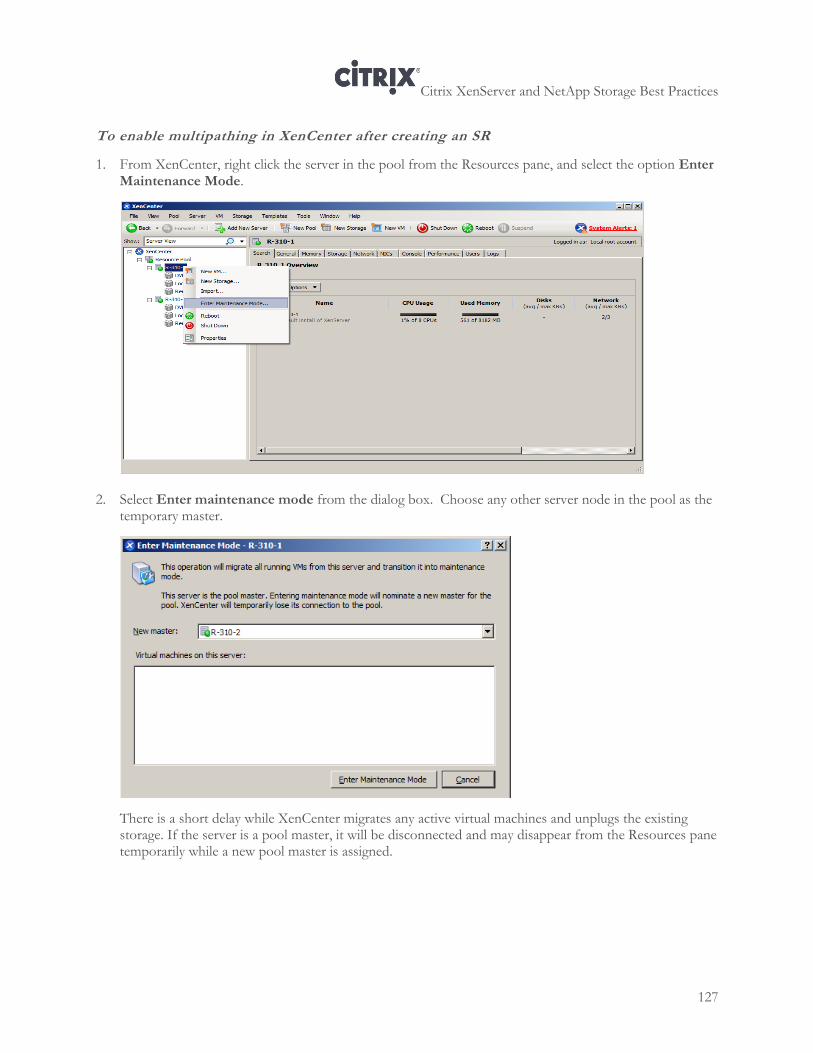
Citrix XenServer and NetApp Storage Best Practices
127
To enable multipathing in XenCenter after creating an SR
1. From XenCenter, right click the server in the pool from the Resources pane, and select the option Enter Maintenance Mode.
2. Select Enter maintenance mode from the dialog box. Choose any other server node in the pool as the
temporary master.
There is a short delay while XenCenter migrates any active virtual machines and unplugs the existing storage. If the server is a pool master, it will be disconnected and may disappear from the Resources pane temporarily while a new pool master is assigned.
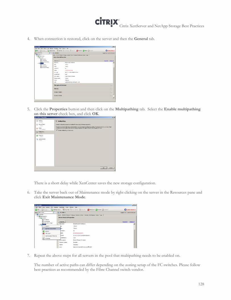
Citrix XenServer and NetApp Storage Best Practices
128
4. When connection is restored, click on the server and then the General tab.
5. Click the Properties button and then click on the Multipathing tab. Select the Enable multipathing on this server check box, and click OK.
There is a short delay while XenCenter saves the new storage configuration.
6. Take the server back out of Maintenance mode by right clicking on the server in the Resources pane and click Exit Maintenance Mode.
7. Repeat the above steps for all servers in the pool that multipathing needs to be enabled on.
The number of active paths can differ depending on the zoning setup of the FC switches. Please follow best practices as recommended by the Fibre Channel switch vendor.
Citrix XenServer and NetApp Storage Best Practices
129
Verifying Multipathing is Working Correctly
After you configure multipathing, consider verifying not only that both paths are active but also that the data sent and received on both paths is balanced. If multipathing is configured incorrectly, it is possible, in some cases, for both paths to be active but have less than optimal throughput or even have one path that barely works (but is still marked active).
To detect this issue, try using the following procedures.
To check if XenServer is using the optimal path
1. Using a utility like Putty, connect to the NetApp storage.
2. In the CLI window, enter the following command to generate traffic:
lun stats –o
3. Examine the results.
If you see a small amount of I/O on the partner (non-preferred) path, your configuration is probably correct. (The command generates a small amount of traffic.)
If you see traffic and not just I/O, there might be a problem and your multipathing configuration might be incorrect.
Tip: To reset these counters, run the lun stats –z command.
To display stats on each path to a LUN or volume
1. From the XenServer host, in the Console tab, run the following to display I/O stats for a VM:
vmstat
2. From the XenServer host, in the Console tab, run the following:
iostat
To verify multipathing is working (cable push/pull test)
Do not perform this procedure in a production environment. After an array is in production, this procedure may cause an outage.
1. Unplug one of the cables from HBA port on the host.
Assuming your environment originally had 8 paths to the storage, if XenCenter says4 of 8paths are active, multipathing is working correctly.
2. Check the storage traffic failed over by running the following command:
lun stats -o -i<checking interval><path to LUN>
Check to make sure the traffic has resumed on the HBA that is still active.
Citrix XenServer and NetApp Storage Best Practices
130
Troubleshooting Multipathing
When troubleshooting multipathing issues, setting the multipathing verbosity to the maximum in the multipath.conf file increase the number of prio errors that are captures in the syslog, which can make it easier to see errors.
To increase the verbosity for multipathing
1. Using a program like WinSCP or the CLI method of your choice, on each host in the pool, open the /etc/multipath.conf file.
2. Find the NetApp section, in the defaults section, add the keyword “verbosity” and increase the verbosity to the maximum (6):
defaults
{
user_friendly_names no
pg_prio_calc avg
verbosity 6
}
Note: Valid values for the verbosity keyword are 0 to 6, where 6 is the maximum verbosity. By default, without specifying a keyword, verbosity is set to 2.
3. Save the multipath.conf file and close it. Prio errors will begin to appear in the syslog.
Citrix XenServer and NetApp Storage Best Practices
131
Chapter 12: Configuring a High Availability Pair of Controllers (ALUA)
This chapter explains how to configure a high availability pair of NetApp controllers using Asymmetric Logical Unit Access (ALUA) for the Fibre Channel protocol:
An overview to configuring a pair of high availability controllers and the purpose of ALUA
An overview of how to configure ALUA
Information about creating the LUN and SR
How to verify your ALUA configuration
How to troubleshoot your ALUA configuration
Overview
When you have multiple controllers on a NetApp, it is possible to set them up in a high availability configuration so that if one controller fails the other controller takes over and the LUN does not experience a service interruption.
Using NetApp terminology, this is known as configuring a high availability pair of controllers. However, to set up this configuration to work with virtualized servers, you must enable ALUA or else it introduces inefficient paths between the XenServer host and the storage.
NetApp utilizes ALUA to ensure storage traffic takes the most efficient path when users configure a second storage controller for failover. In a failover configuration, the second controller, known as the partner controller, can access the LUN if the primary controller (owner) associated with the LUN fails.
ALUA Overview
ALUA is a SCSI standard some arrays use to ensure that storage traffic takes the most efficient path from the host to the storage. If ALUA is not enabled correctly on both the NetApp and XenServer host, storage traffic may experience latency and the NetApp may automatically contact NetApp support.
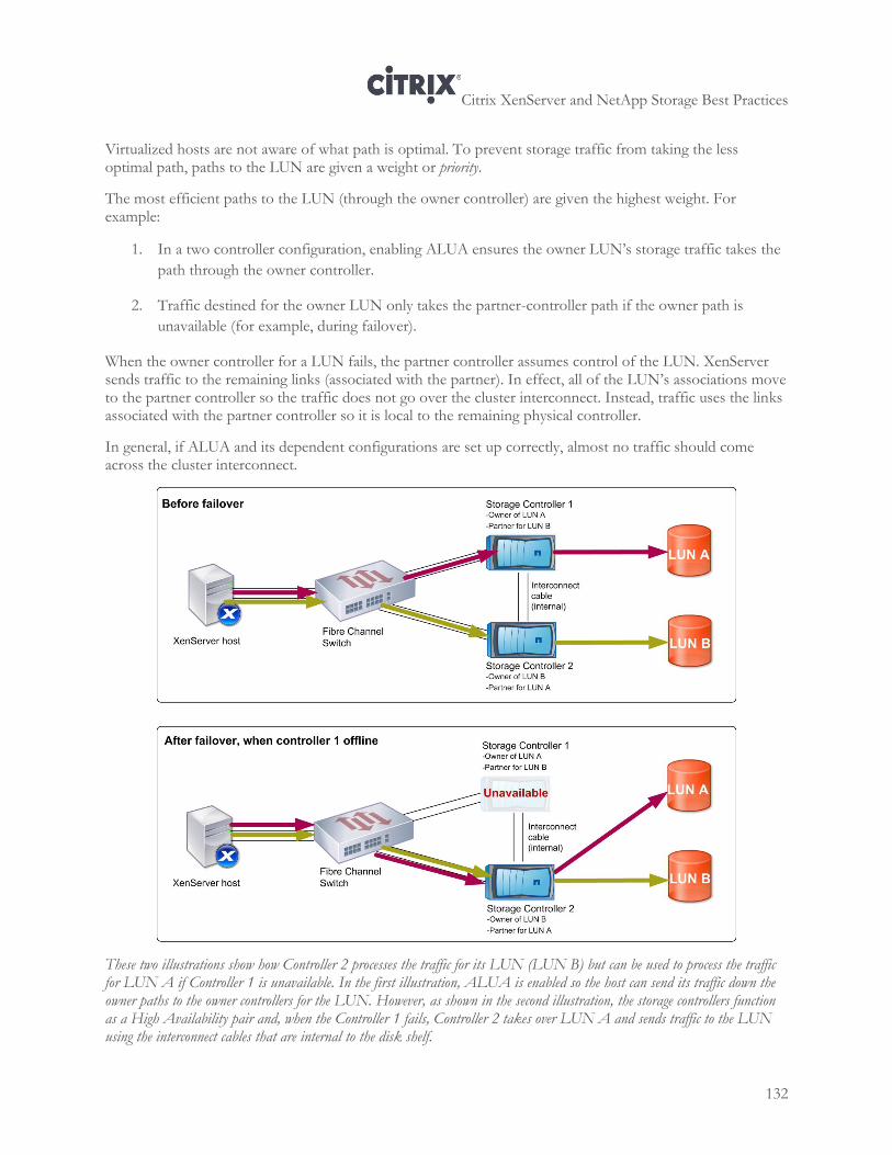
Citrix XenServer and NetApp Storage Best Practices
132
Virtualized hosts are not aware of what path is optimal. To prevent storage traffic from taking the less optimal path, paths to the LUN are given a weight or priority.
The most efficient paths to the LUN (through the owner controller) are given the highest weight. For example:
1. In a two controller configuration, enabling ALUA ensures the owner LUN’s storage traffic takes the
path through the owner controller.
2. Traffic destined for the owner LUN only takes the partner-controller path if the owner path is
unavailable (for example, during failover).
When the owner controller for a LUN fails, the partner controller assumes control of the LUN. XenServer sends traffic to the remaining links (associated with the partner). In effect, all of the LUN’s associations move to the partner controller so the traffic does not go over the cluster interconnect. Instead, traffic uses the links associated with the partner controller so it is local to the remaining physical controller.
In general, if ALUA and its dependent configurations are set up correctly, almost no traffic should come across the cluster interconnect.
These two illustrations show how Controller 2 processes the traffic for its LUN (LUN B) but can be used to process the traffic for LUN A if Controller 1 is unavailable. In the first illustration, ALUA is enabled so the host can send its traffic down the owner paths to the owner controllers for the LUN. However, as shown in the second illustration, the storage controllers function as a High Availability pair and, when the Controller 1 fails, Controller 2 takes over LUN A and sends traffic to the LUN using the interconnect cables that are internal to the disk shelf.
Citrix XenServer and NetApp Storage Best Practices
133
When owner controller (controller 1) for LUN A fails, the partner controller (controller 2) assumes control of the LUN.As a result, until controller 1 comes back online, controller 2 is processing storage traffic for both LUN A and LUN B.
Note: Although traditionally ALUA has been a Fibre Channel standard, NetApp supports it for iSCSI as of Data ONTAP 8.1. However, iSCSI is beyond the scope of this guide.
ALUA Configuration Overview
Enabling ALUA requires two performing major tasks on the XenServer and NetApp:
On each XenServer host in the pool, you must modify the multipath.conf file to use the ALUA
settings
On the owner NetApp controller, you must enable ALUA when you create the initiator group
Without these two configurations, ALUA will not work. However, to perform these tasks need to perform significantly more tasks to support the process. At a high level, configuring ALUA requires the following tasks:
1. Configuring a pair of High Availability controllers, including ensuring the correct licenses are present,
the operating systems match, and the options match.
2. Retrieving the WWPNs from the HBAs on the XenServer host.
3. Configuring zoning on the switch:
4. Configuring the NetApp:
a. Creating the initiator group on the owner controller (and enabling ALUA in it).
b. Creating the LUN on the owner controller.
c. Verifying the NetApp High Availability feature is enabled.
5. Configure storage on each XenServer host in the pool.
a. Configuring at least two Fibre Channel ports as targets.
b. Editing the multipath.conf file.
c. Enabling multipathing in XenCenter (or using the CLI, if desired).
d. Creating the SR. (If you select the pool node in XenCenter when you create the SR, you only
need to create the SR once.)
Instead of saving verification until the end, the configuration also includes verification stages after each major task to make it easier to isolate issues.
Note: All of the examples provided assume you are performing a configuration with two HBA ports and two controllers, which results in eight active paths. If your configuration is more complex and you have more
Citrix XenServer and NetApp Storage Best Practices
134
active paths, the number of paths active at different points in this process will be different from those listed in this chapter.
Preparing to Configure ALUA
This section provides information about how to configure ALUA, including the following:
Minimum requirements
An overview of configuration, including how to configure your physical environment, prepare your
controllers, retrieve WWPNs, and zone switches
How to configure the required settings on the NetApp and in XenServer
Minimum Requirements
Fibre Channel protocol configured
Fibre Channel switch; however, two switches is the NetApp best practice
Each host in the pool must have at least two Fibre Channel HBA ports (either (a) one HBA with two
ports or (b) two HBAs with one port each)
An ALUA-compliant NetApp array with two storage controllers
A version of NetApp Data ONTAP that is compatible with ALUA (see your ONTAP
documentation)
Preparing Your Physical Environment
This section describes the physical equipment configurations you should prepare before you begin to set up a high availability pair of controllers and configure ALUA.
Configuring ALUA requires two storage controllers, which can either be in the same chassis or in different chassis. Before configuring ALUA, if the two controllers are not already connected, you must connect them.
If the controllers are in different chassis, you must make an interconnect link between the two controllers using a physical interconnect cable. If the controllers are in the same chassis, they can use the internal interconnect links in the chassis.
For more information about installing controllers or connecting controllers in different chassis, see your NetApp documentation.
When enabling ALUA with Fibre Channel, subnet configuration is not relevant so the controllers can be on same subnet or different subnets.
Configuring a High Availability Pair of Controllers
NetApp uses the term High Availability to refer to two storage controllers configured for redundancy so they can provide a failover path to the same LUN.
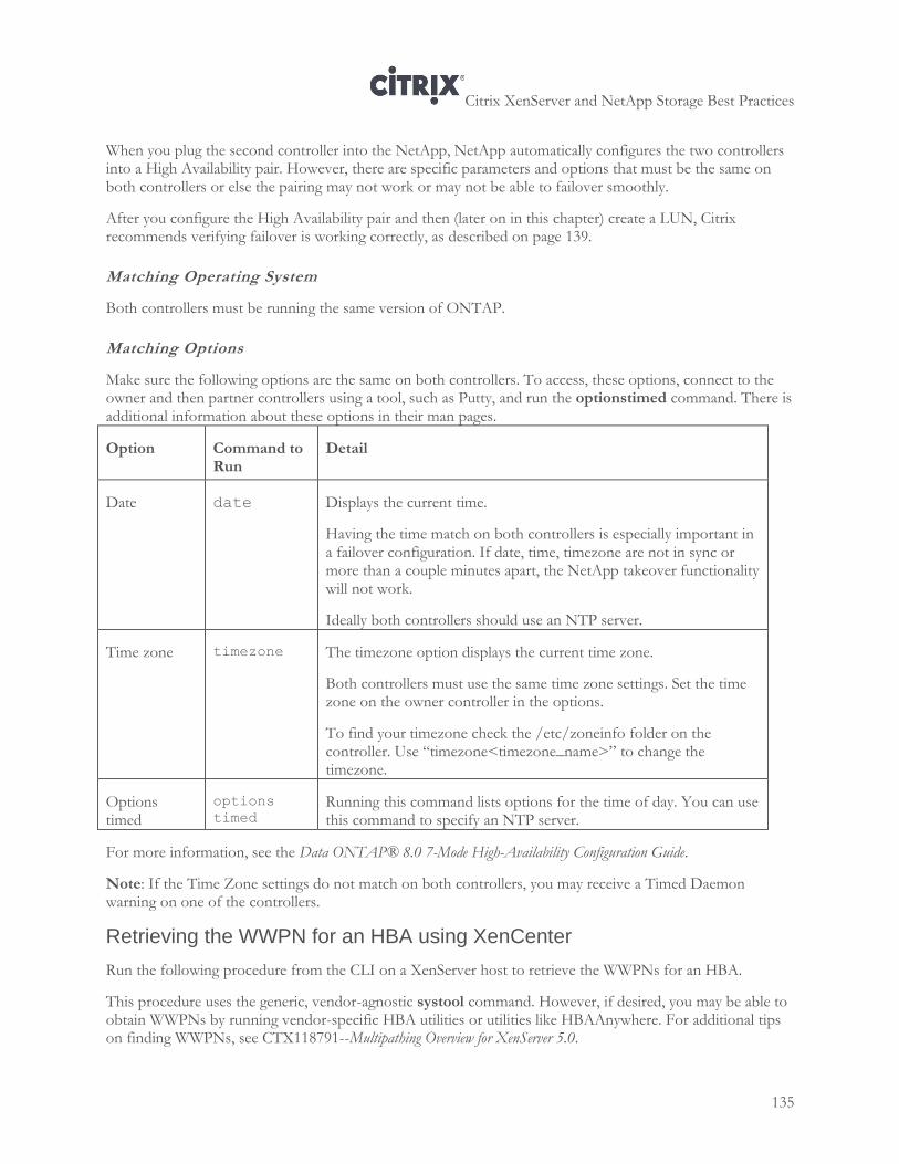
Citrix XenServer and NetApp Storage Best Practices
135
When you plug the second controller into the NetApp, NetApp automatically configures the two controllers into a High Availability pair. However, there are specific parameters and options that must be the same on both controllers or else the pairing may not work or may not be able to failover smoothly.
After you configure the High Availability pair and then (later on in this chapter) create a LUN, Citrix recommends verifying failover is working correctly, as described on page 139.
Matching Operating System
Both controllers must be running the same version of ONTAP.
Matching Options
Make sure the following options are the same on both controllers. To access, these options, connect to the owner and then partner controllers using a tool, such as Putty, and run the optionstimed command. There is additional information about these options in their man pages.
Option Command to Run
Detail
Date date
Displays the current time.
Having the time match on both controllers is especially important in a failover configuration. If date, time, timezone are not in sync or more than a couple minutes apart, the NetApp takeover functionality will not work.
Ideally both controllers should use an NTP server.
Time zone timezone
The timezone option displays the current time zone.
Both controllers must use the same time zone settings. Set the time zone on the owner controller in the options.
To find your timezone check the /etc/zoneinfo folder on the controller. Use “timezone<timezone_name>” to change the timezone.
Options timed
options
timed Running this command lists options for the time of day. You can use this command to specify an NTP server.
For more information, see the Data ONTAP® 8.0 7-Mode High-Availability Configuration Guide.
Note: If the Time Zone settings do not match on both controllers, you may receive a Timed Daemon warning on one of the controllers.
Retrieving the WWPN for an HBA using XenCenter
Run the following procedure from the CLI on a XenServer host to retrieve the WWPNs for an HBA.
This procedure uses the generic, vendor-agnostic systool command. However, if desired, you may be able to obtain WWPNs by running vendor-specific HBA utilities or utilities like HBAAnywhere. For additional tips on finding WWPNs, see CTX118791--Multipathing Overview for XenServer 5.0.
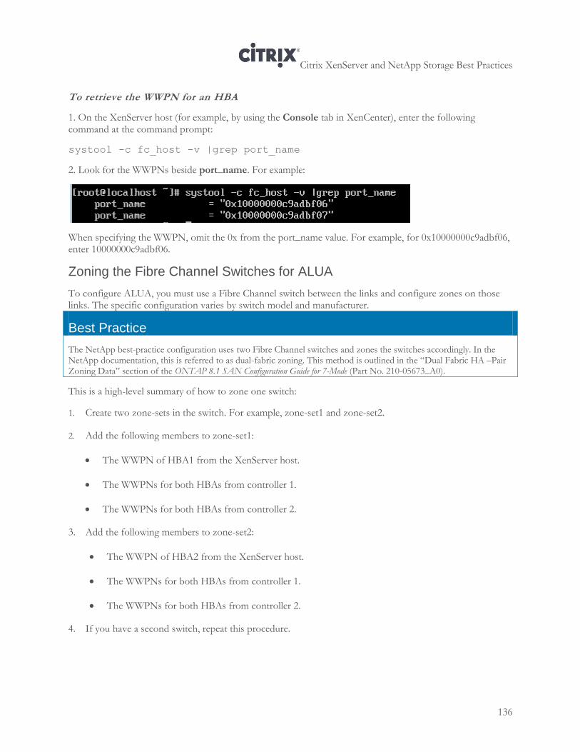
Citrix XenServer and NetApp Storage Best Practices
136
To retrieve the WWPN for an HBA
1. On the XenServer host (for example, by using the Console tab in XenCenter), enter the following command at the command prompt:
systool -c fc_host -v |grep port_name
2. Look for the WWPNs beside port_name. For example:
When specifying the WWPN, omit the 0x from the port_name value. For example, for 0x10000000c9adbf06, enter 10000000c9adbf06.
Zoning the Fibre Channel Switches for ALUA
To configure ALUA, you must use a Fibre Channel switch between the links and configure zones on those links. The specific configuration varies by switch model and manufacturer.
Best Practice
The NetApp best-practice configuration uses two Fibre Channel switches and zones the switches accordingly. In the NetApp documentation, this is referred to as dual-fabric zoning. This method is outlined in the “Dual Fabric HA –Pair Zoning Data” section of the ONTAP 8.1 SAN Configuration Guide for 7-Mode (Part No. 210-05673_A0).
This is a high-level summary of how to zone one switch:
1. Create two zone-sets in the switch. For example, zone-set1 and zone-set2.
2. Add the following members to zone-set1:
The WWPN of HBA1 from the XenServer host.
The WWPNs for both HBAs from controller 1.
The WWPNs for both HBAs from controller 2.
3. Add the following members to zone-set2:
The WWPN of HBA2 from the XenServer host.
The WWPNs for both HBAs from controller 1.
The WWPNs for both HBAs from controller 2.
4. If you have a second switch, repeat this procedure.
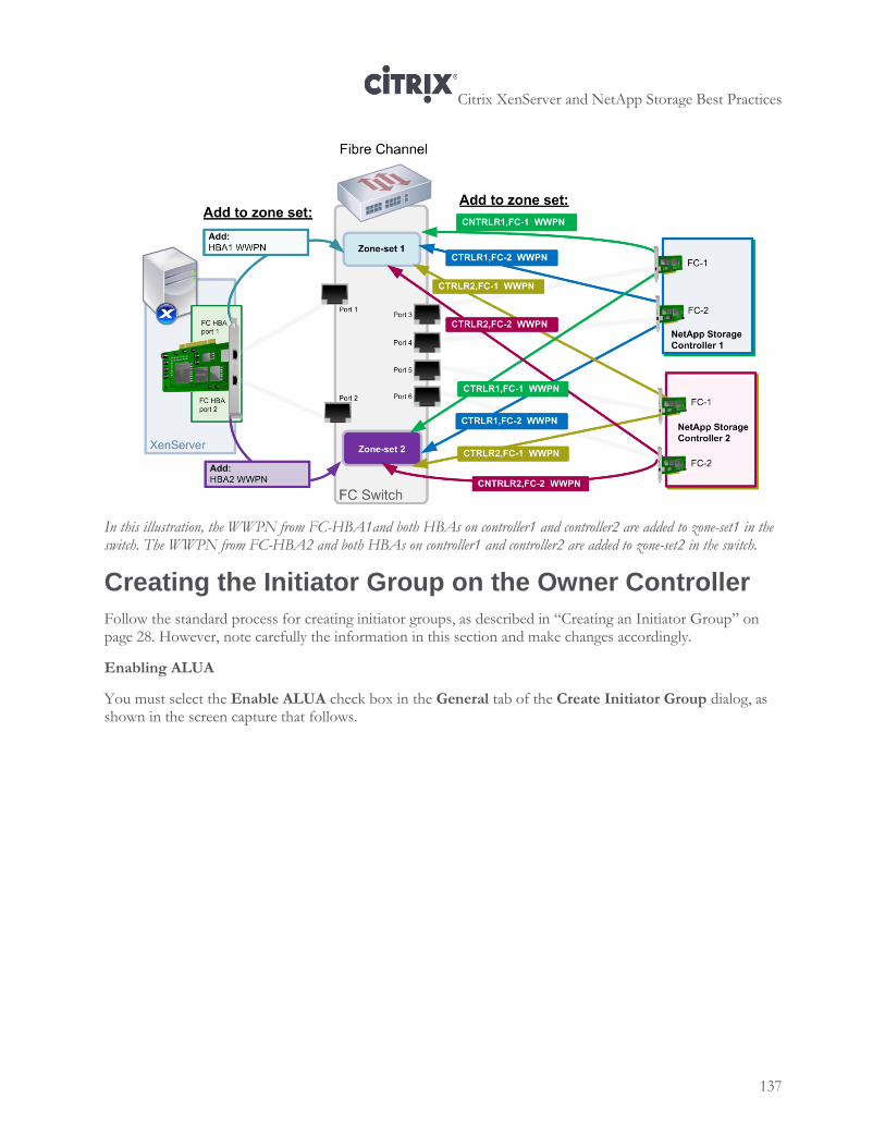
Citrix XenServer and NetApp Storage Best Practices
137
In this illustration, the WWPN from FC-HBA1and both HBAs on controller1 and controller2 are added to zone-set1 in the switch. The WWPN from FC-HBA2 and both HBAs on controller1 and controller2 are added to zone-set2 in the switch.
Creating the Initiator Group on the Owner Controller
Follow the standard process for creating initiator groups, as described in “Creating an Initiator Group” on page 28. However, note carefully the information in this section and make changes accordingly.
Enabling ALUA
You must select the Enable ALUA check box in the General tab of the Create Initiator Group dialog, as shown in the screen capture that follows.
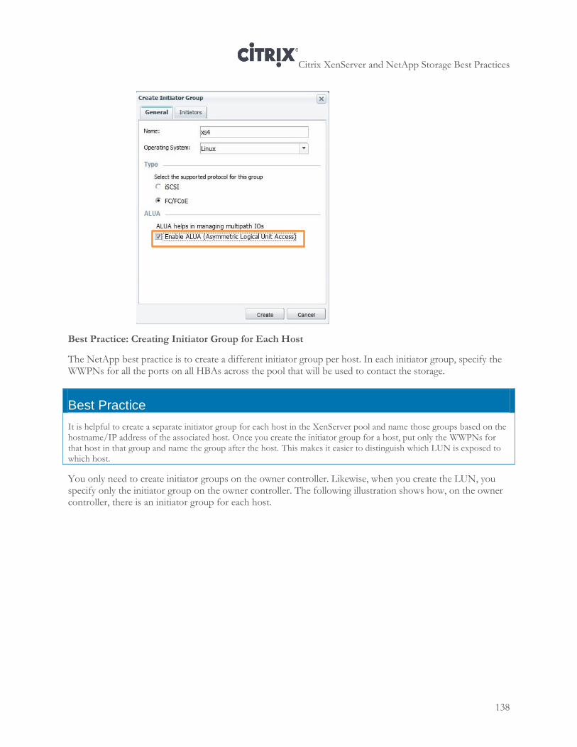
Citrix XenServer and NetApp Storage Best Practices
138
Best Practice: Creating Initiator Group for Each Host
The NetApp best practice is to create a different initiator group per host. In each initiator group, specify the WWPNs for all the ports on all HBAs across the pool that will be used to contact the storage.
Best Practice
It is helpful to create a separate initiator group for each host in the XenServer pool and name those groups based on the hostname/IP address of the associated host. Once you create the initiator group for a host, put only the WWPNs for that host in that group and name the group after the host. This makes it easier to distinguish which LUN is exposed to which host.
You only need to create initiator groups on the owner controller. Likewise, when you create the LUN, you specify only the initiator group on the owner controller. The following illustration shows how, on the owner controller, there is an initiator group for each host.
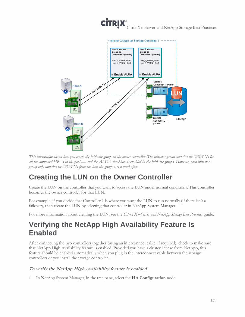
Citrix XenServer and NetApp Storage Best Practices
139
This illustration shows how you create the initiator group on the owner controller. The initiator group contains the WWPNs for all the connected HBAs in the pool — and the ALUA checkbox is enabled in the initiator groups. However, each initiator group only contains the WWPNs from the host the group was named after.
Creating the LUN on the Owner Controller
Create the LUN on the controller that you want to access the LUN under normal conditions. This controller becomes the owner controller for that LUN.
For example, if you decide that Controller 1 is where you want the LUN to run normally (if there isn’t a failover), then create the LUN by selecting that controller in NetApp System Manager.
For more information about creating the LUN, see the Citrix XenServer and NetApp Storage Best Practices guide.
Verifying the NetApp High Availability Feature Is Enabled
After connecting the two controllers together (using an interconnect cable, if required), check to make sure that NetApp High Availability feature is enabled. Provided you have a cluster license from NetApp, this feature should be enabled automatically when you plug in the interconnect cable between the storage controllers or you install the storage controller.
To verify the NetApp High Availability feature is enabled
1. In NetApp System Manager, in the tree pane, select the HA Configuration node.
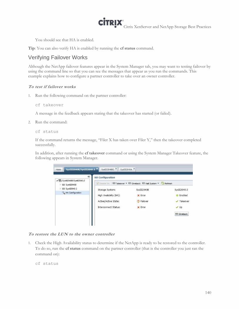
Citrix XenServer and NetApp Storage Best Practices
140
You should see that HA is enabled.
Tip: You can also verify HA is enabled by running the cf status command.
Verifying Failover Works
Although the NetApp failover features appear in the System Manager tab, you may want to testing failover by using the command line so that you can see the messages that appear as you run the commands. This example explains how to configure a partner controller to take over an owner controller.
To test if failover works
1. Run the following command on the partner controller:
cf takeover
A message in the feedback appears stating that the takeover has started (or failed).
2. Run the command:
cf status
If the command returns the message, “Filer X has taken over Filer Y,” then the takeover completed successfully.
In addition, after running the cf takeover command or using the System Manager Takeover feature, the following appears in System Manager.
To restore the LUN to the owner controller
1. Check the High Availability status to determine if the NetApp is ready to be restored to the controller.
To do so, run the cf status command on the partner controller (that is the controller you just ran the
command on):
cf status
Citrix XenServer and NetApp Storage Best Practices
141
2. If the NetApp returns “Filer X is ready for giveback,” run the following command on the partner
controller:
cf giveback
Creating a Multipathed XenServer SR for ALUA
Creating a XenServer SR for use with ALUA requires the SR be accessible through multiple paths. Configuring a multipathed SR for XenServer requires four tasks:
1. Configuring the Fibre Channel ports as targets.
2. Editing the multipath.conf file so it uses the ALUA settings for NetApp.
3. Enabling multipathing in XenCenter.
4. Creating the SR.
Configuring the Fibre Channel Ports as Targets
For XenServer to map an SR to a Fibre Channel LUN when ALUA is enabled, you must configure at least two of the Fibre Channel ports on the storage as the target. Unless the ports are configured as targets, XenServer cannot detect them when it tries to connect to the storage when it is mapping the SR to the LUN.
To configure the Fibre Channel ports on the controller as targets
1. Connect to the controller using a utility such as Putty.
2. Run the fcadminconfig command to display if the ports on the controller are configured as initiators or targets.
3. If the ports are not already offline, run the following command to set them offline:
fcadminconfig –d <adapter_name>
4. After you determine what port you want to configure as the target, run the fcadmingconfig –t <type><adapter_name>command. For example, to configure port 0c as the target, run:
fcadminconfig –t target 0c
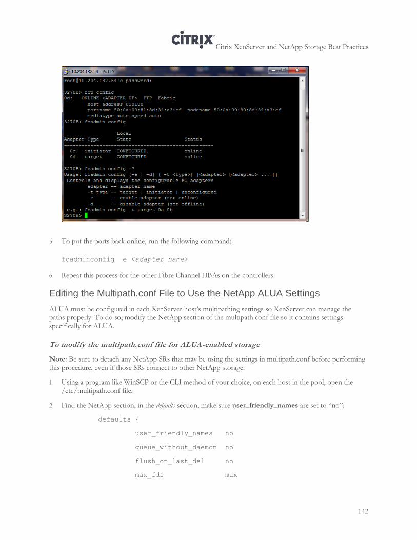
Citrix XenServer and NetApp Storage Best Practices
142
5. To put the ports back online, run the following command:
fcadminconfig –e <adapter_name>
6. Repeat this process for the other Fibre Channel HBAs on the controllers.
Editing the Multipath.conf File to Use the NetApp ALUA Settings
ALUA must be configured in each XenServer host’s multipathing settings so XenServer can manage the paths properly. To do so, modify the NetApp section of the multipath.conf file so it contains settings specifically for ALUA.
To modify the multipath.conf file for ALUA-enabled storage
Note: Be sure to detach any NetApp SRs that may be using the settings in multipath.conf before performing this procedure, even if those SRs connect to other NetApp storage.
1. Using a program like WinSCP or the CLI method of your choice, on each host in the pool, open the /etc/multipath.conf file.
2. Find the NetApp section, in the defaults section, make sure user_friendly_names are set to “no”:
defaults {
user_friendly_names no
queue_without_daemon no
flush_on_last_del no
max_fds max
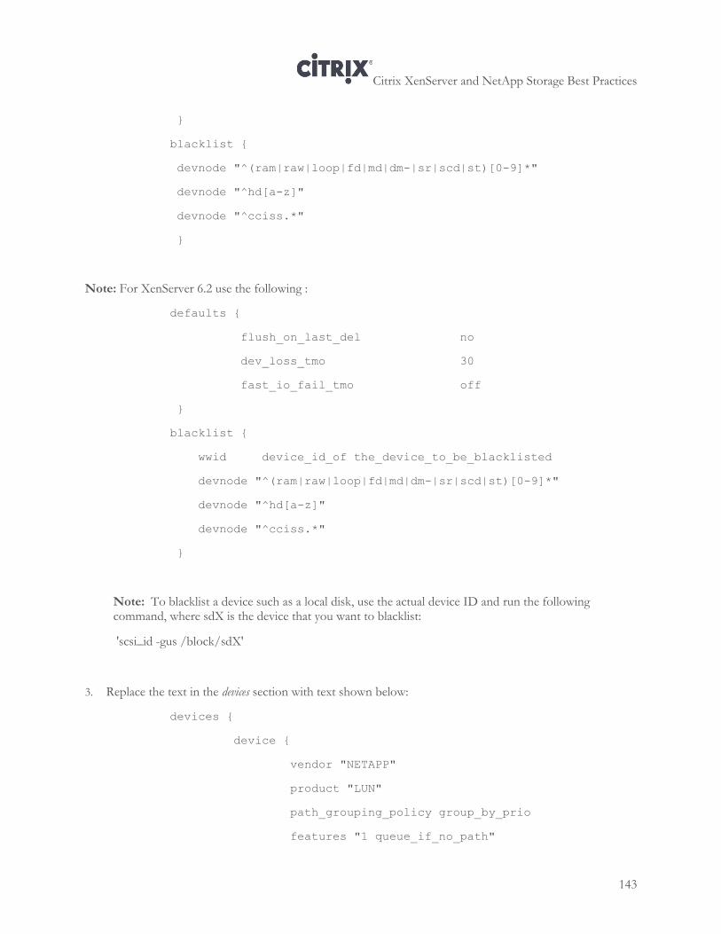
Citrix XenServer and NetApp Storage Best Practices
143
}
blacklist {
devnode "^(ram|raw|loop|fd|md|dm-|sr|scd|st)[0-9]*"
devnode "^hd[a-z]"
devnode "^cciss.*"
}
Note: For XenServer 6.2 use the following :
defaults {
flush_on_last_del no
dev_loss_tmo 30
fast_io_fail_tmo off
}
blacklist {
wwid device_id_of the_device_to_be_blacklisted
devnode "^(ram|raw|loop|fd|md|dm-|sr|scd|st)[0-9]*"
devnode "^hd[a-z]"
devnode "^cciss.*"
}
Note: To blacklist a device such as a local disk, use the actual device ID and run the following command, where sdX is the device that you want to blacklist:
'scsi_id -gus /block/sdX'
3. Replace the text in the devices section with text shown below:
devices {
device {
vendor "NETAPP"
product "LUN"
path_grouping_policy group_by_prio
features "1 queue_if_no_path"
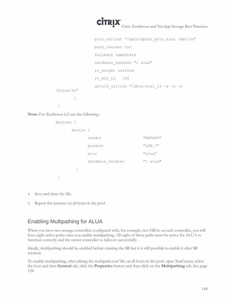
Citrix XenServer and NetApp Storage Best Practices
144
prio_callout "/sbin/mpath_prio_alua /dev/%n"
path_checker tur
failback immediate
hardware_handler "1 alua"
rr_weight uniform
rr_min_io 128
getuid_callout "/sbin/scsi_id -g -u -s
/block/%n"
}
}
Note: For XenServer 6.2 use the following :
devices {
device {
vendor "NETAPP"
product "LUN.*"
prio "alua"
hardware_handler "1 alua"
}
}
4. Save and close the file.
5. Repeat this process on all hosts in the pool.
Enabling Multipathing for ALUA
When you have two storage controllers configured with, for example, two HBAs on each controller, you will have eight active paths once you enable multipathing. All eight of these paths must be active for ALUA to function correctly and the owner controller to failover successfully.
Ideally, multipathing should be enabled before creating the SR but it is still possible to enable it after SR creation.
To enable multipathing, after editing the multipath.conf file on all hosts in the pool, open XenCenter, select the host and then General tab, click the Properties button and then click on the Multipathing tab. See page 124.
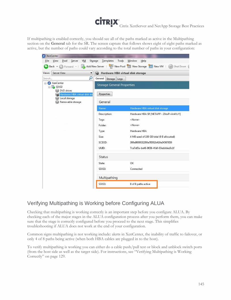
Citrix XenServer and NetApp Storage Best Practices
145
If multipathing is enabled correctly, you should see all of the paths marked as active in the Multipathing section on the General tab for the SR. The screen capture that follows shows eight of eight paths marked as active, but the number of paths could vary according to the total number of paths in your configuration:
Verifying Multipathing is Working before Configuring ALUA
Checking that multipathing is working correctly is an important step before you configure ALUA. By checking each of the major stages in the ALUA configuration process after you perform them, you can make sure that the stage is correctly configured before you proceed to the next stage. This simplifies troubleshooting if ALUA does not work at the end of your configuration.
Common signs multipathing is not working include: alerts in XenCenter, the inability of traffic to failover, or only 4 of 8 paths being active (when both HBA cables are plugged in to the host).
To verify multipathing is working you can either do a cable push/pull test or block and unblock switch ports (from the host side as well as the target side). For instructions, see “Verifying Multipathing is Working Correctly” on page 129.
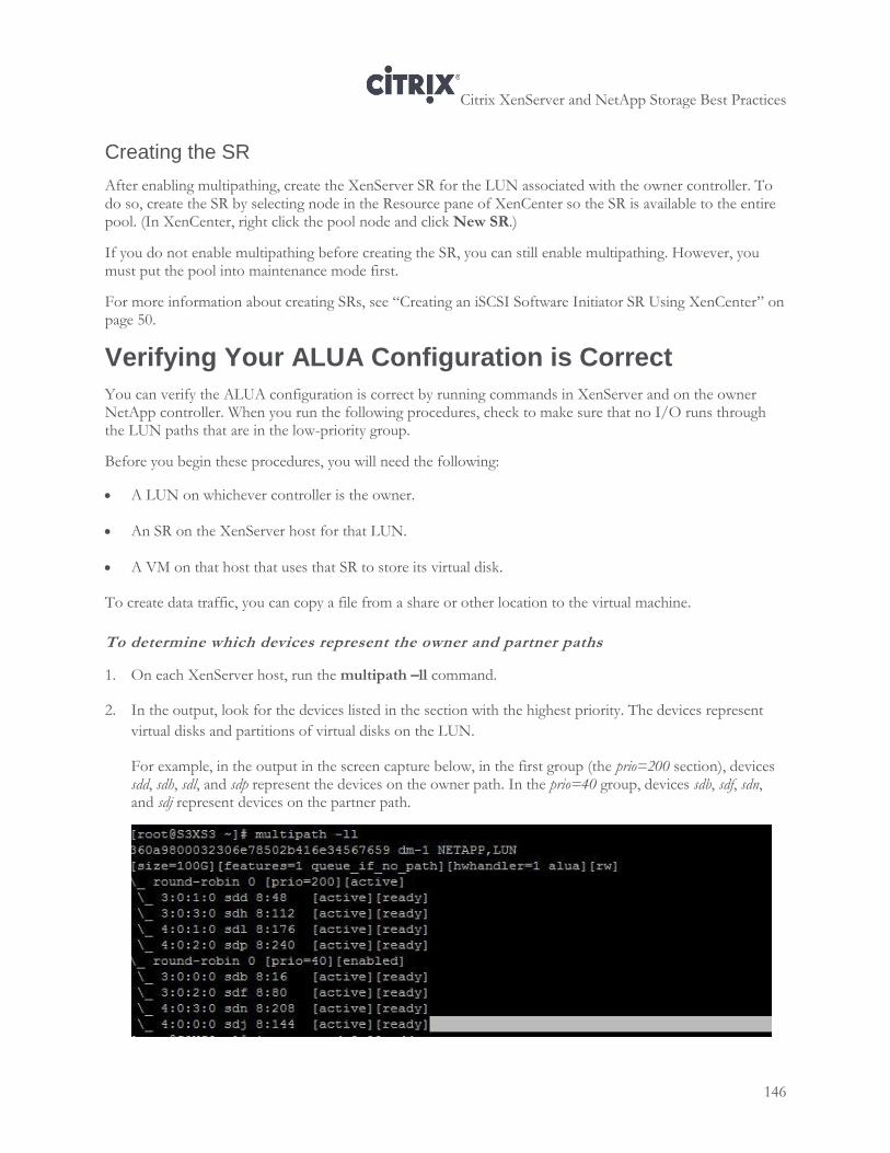
Citrix XenServer and NetApp Storage Best Practices
146
Creating the SR
After enabling multipathing, create the XenServer SR for the LUN associated with the owner controller. To do so, create the SR by selecting node in the Resource pane of XenCenter so the SR is available to the entire pool. (In XenCenter, right click the pool node and click New SR.)
If you do not enable multipathing before creating the SR, you can still enable multipathing. However, you must put the pool into maintenance mode first.
For more information about creating SRs, see “Creating an iSCSI Software Initiator SR Using XenCenter” on page 50.
Verifying Your ALUA Configuration is Correct
You can verify the ALUA configuration is correct by running commands in XenServer and on the owner NetApp controller. When you run the following procedures, check to make sure that no I/O runs through the LUN paths that are in the low-priority group.
Before you begin these procedures, you will need the following:
A LUN on whichever controller is the owner.
An SR on the XenServer host for that LUN.
A VM on that host that uses that SR to store its virtual disk.
To create data traffic, you can copy a file from a share or other location to the virtual machine.
To determine which devices represent the owner and partner paths
1. On each XenServer host, run the multipath –ll command.
2. In the output, look for the devices listed in the section with the highest priority. The devices represent
virtual disks and partitions of virtual disks on the LUN.
For example, in the output in the screen capture below, in the first group (the prio=200 section), devices sdd, sdh, sdl, and sdp represent the devices on the owner path. In the prio=40 group, devices sdb, sdf, sdn, and sdj represent devices on the partner path.
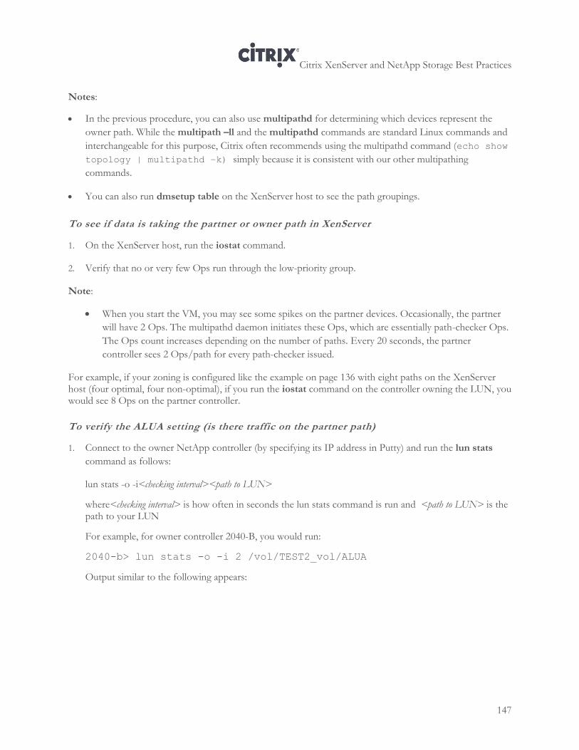
Citrix XenServer and NetApp Storage Best Practices
147
Notes:
In the previous procedure, you can also use multipathd for determining which devices represent the
owner path. While the multipath –ll and the multipathd commands are standard Linux commands and
interchangeable for this purpose, Citrix often recommends using the multipathd command (echo show
topology | multipathd –k) simply because it is consistent with our other multipathing
commands.
You can also run dmsetup table on the XenServer host to see the path groupings.
To see if data is taking the partner or owner path in XenServer
1. On the XenServer host, run the iostat command.
2. Verify that no or very few Ops run through the low-priority group.
Note:
When you start the VM, you may see some spikes on the partner devices. Occasionally, the partner
will have 2 Ops. The multipathd daemon initiates these Ops, which are essentially path-checker Ops.
The Ops count increases depending on the number of paths. Every 20 seconds, the partner
controller sees 2 Ops/path for every path-checker issued.
For example, if your zoning is configured like the example on page 136 with eight paths on the XenServer host (four optimal, four non-optimal), if you run the iostat command on the controller owning the LUN, you would see 8 Ops on the partner controller.
To verify the ALUA setting (is there traffic on the partner path)
1. Connect to the owner NetApp controller (by specifying its IP address in Putty) and run the lun stats
command as follows:
lun stats -o -i<checking interval><path to LUN>
where<checking interval> is how often in seconds the lun stats command is run and <path to LUN> is the path to your LUN
For example, for owner controller 2040-B, you would run:
2040-b> lun stats -o -i 2 /vol/TEST2_vol/ALUA
Output similar to the following appears:
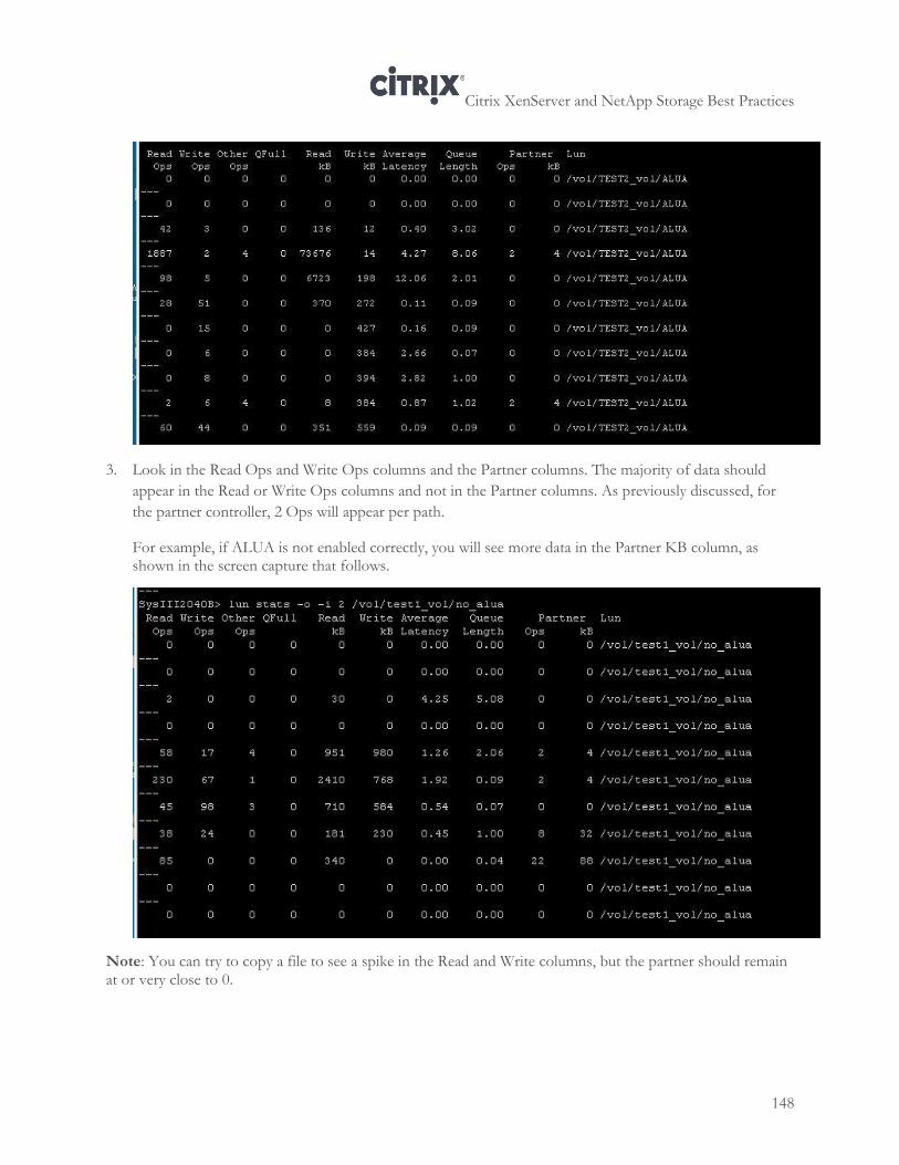
Citrix XenServer and NetApp Storage Best Practices
148
3. Look in the Read Ops and Write Ops columns and the Partner columns. The majority of data should
appear in the Read or Write Ops columns and not in the Partner columns. As previously discussed, for
the partner controller, 2 Ops will appear per path.
For example, if ALUA is not enabled correctly, you will see more data in the Partner KB column, as shown in the screen capture that follows.
Note: You can try to copy a file to see a spike in the Read and Write columns, but the partner should remain at or very close to 0.
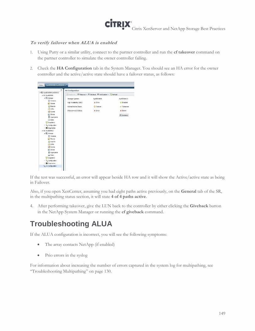
Citrix XenServer and NetApp Storage Best Practices
149
To verify failover when ALUA is enabled
1. Using Putty or a similar utility, connect to the partner controller and run the cf takeover command on
the partner controller to simulate the owner controller failing.
2. Check the HA Configuration tab in the System Manager. You should see an HA error for the owner
controller and the active/active state should have a failover status, as follows:
If the test was successful, an error will appear beside HA row and it will show the Active/active state as being in Failover.
Also, if you open XenCenter, assuming you had eight paths active previously, on the General tab of the SR, in the multipathing status section, it will state 4 of 4 paths active.
4. After performing takeover, give the LUN back to the controller by either clicking the Giveback button
in the NetApp System Manager or running the cf giveback command.
Troubleshooting ALUA
If the ALUA configuration is incorrect, you will see the following symptoms:
The array contacts NetApp (if enabled)
Prio errors in the syslog
For information about increasing the number of errors captured in the system log for multipathing, see
“Troubleshooting Multipathing” on page 130.
Citrix XenServer and NetApp Storage Best Practices
150
Chapter 13: Backup and Recovery
This chapter provides information about configuring back-up and recovery solutions using your NetApp storage and XenServer. It includes information about the following:
Creating and scheduling snapshots for virtual machines
Backing up VM metadata information using the CLI
Backing up storage volumes using NetApp SnapMirror
Configuring XenServer Disaster Recovery
Creating Snapshots for Virtual Machines
A virtual machine snapshot is a record of a running virtual machine at a point in time. When you take a snapshot of a VM, its storage information (the data on the hard drive) and metadata (configuration information) is also saved. When necessary, I/O is temporarily halted while the snapshot is being taken to ensure that a self-consistent disk image can be captured. Unlike VM exports, you can create snapshots without first shutting down the VM.
A snapshot is similar to a normal VM template but it contains all the storage and configuration information for the original VM, including networking information. Snapshots provide a fast way of creating templates that can be exported for backup purposes and then restored, or that can be used to quickly create new VMs.
XenServer snapshots are available for all storage types. XenServer has two types of virtual machine snapshots: regular and quiesced.
Regular snapshots are crash consistent and can be created on all virtual machine and SR types, including Linux virtual machines. Virtual machines snapshots can be created for both running and powered down virtual machines.
Note: To take snapshots for LVM-based storage types (XenServer version 5.5 onwards) the storage repository must be upgraded if it was created on an older version of XenServer, and the volume must be in the default format.
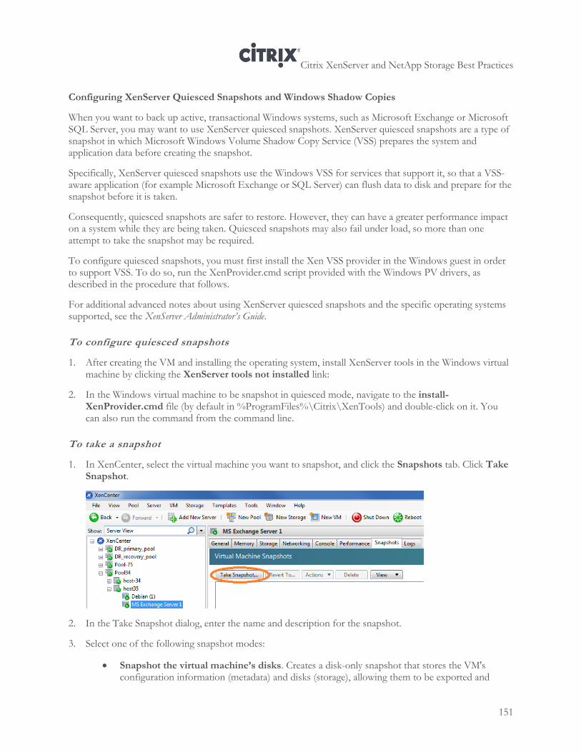
Citrix XenServer and NetApp Storage Best Practices
151
Configuring XenServer Quiesced Snapshots and Windows Shadow Copies
When you want to back up active, transactional Windows systems, such as Microsoft Exchange or Microsoft SQL Server, you may want to use XenServer quiesced snapshots. XenServer quiesced snapshots are a type of snapshot in which Microsoft Windows Volume Shadow Copy Service (VSS) prepares the system and application data before creating the snapshot.
Specifically, XenServer quiesced snapshots use the Windows VSS for services that support it, so that a VSS-aware application (for example Microsoft Exchange or SQL Server) can flush data to disk and prepare for the snapshot before it is taken.
Consequently, quiesced snapshots are safer to restore. However, they can have a greater performance impact on a system while they are being taken. Quiesced snapshots may also fail under load, so more than one attempt to take the snapshot may be required.
To configure quiesced snapshots, you must first install the Xen VSS provider in the Windows guest in order to support VSS. To do so, run the XenProvider.cmd script provided with the Windows PV drivers, as described in the procedure that follows.
For additional advanced notes about using XenServer quiesced snapshots and the specific operating systems supported, see the XenServer Administrator’s Guide.
To configure quiesced snapshots
1. After creating the VM and installing the operating system, install XenServer tools in the Windows virtual machine by clicking the XenServer tools not installed link:
2. In the Windows virtual machine to be snapshot in quiesced mode, navigate to the install-XenProvider.cmd file (by default in %ProgramFiles%\Citrix\XenTools) and double-click on it. You can also run the command from the command line.
To take a snapshot
1. In XenCenter, select the virtual machine you want to snapshot, and click the Snapshots tab. Click Take Snapshot.
2. In the Take Snapshot dialog, enter the name and description for the snapshot.
3. Select one of the following snapshot modes:
Snapshot the virtual machine’s disks. Creates a disk-only snapshot that stores the VM's configuration information (metadata) and disks (storage), allowing them to be exported and
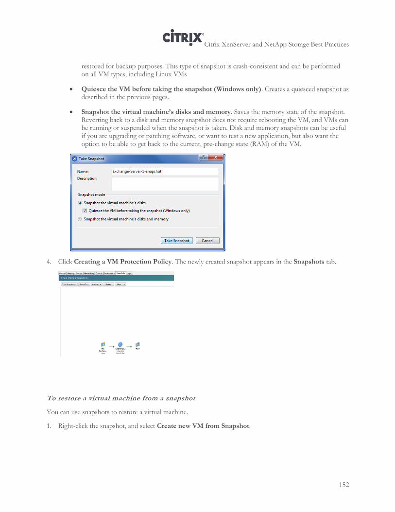
Citrix XenServer and NetApp Storage Best Practices
152
restored for backup purposes. This type of snapshot is crash-consistent and can be performed on all VM types, including Linux VMs
Quiesce the VM before taking the snapshot (Windows only). Creates a quiesced snapshot as described in the previous pages.
Snapshot the virtual machine’s disks and memory. Saves the memory state of the snapshot. Reverting back to a disk and memory snapshot does not require rebooting the VM, and VMs can be running or suspended when the snapshot is taken. Disk and memory snapshots can be useful if you are upgrading or patching software, or want to test a new application, but also want the option to be able to get back to the current, pre-change state (RAM) of the VM.
4. Click Creating a VM Protection Policy. The newly created snapshot appears in the Snapshots tab.
To restore a virtual machine from a snapshot
You can use snapshots to restore a virtual machine.
1. Right-click the snapshot, and select Create new VM from Snapshot.
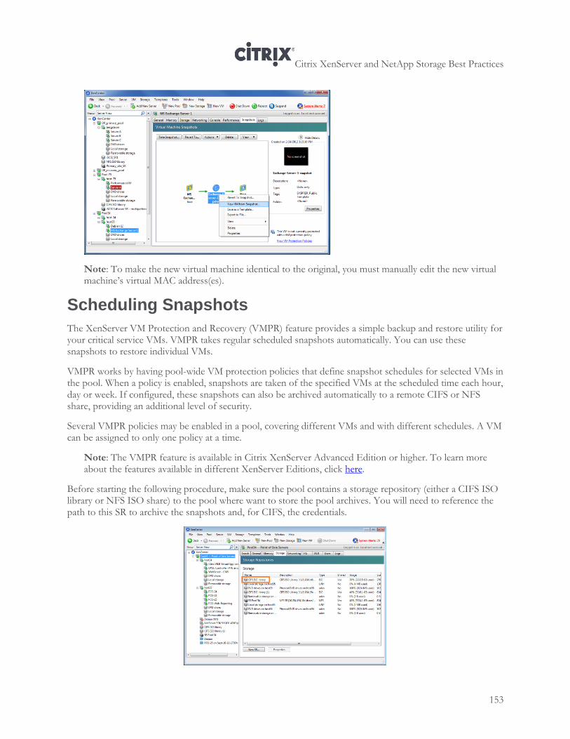
Citrix XenServer and NetApp Storage Best Practices
153
Note: To make the new virtual machine identical to the original, you must manually edit the new virtual machine’s virtual MAC address(es).
Scheduling Snapshots
The XenServer VM Protection and Recovery (VMPR) feature provides a simple backup and restore utility for your critical service VMs. VMPR takes regular scheduled snapshots automatically. You can use these snapshots to restore individual VMs.
VMPR works by having pool-wide VM protection policies that define snapshot schedules for selected VMs in the pool. When a policy is enabled, snapshots are taken of the specified VMs at the scheduled time each hour, day or week. If configured, these snapshots can also be archived automatically to a remote CIFS or NFS share, providing an additional level of security.
Several VMPR policies may be enabled in a pool, covering different VMs and with different schedules. A VM can be assigned to only one policy at a time.
Note: The VMPR feature is available in Citrix XenServer Advanced Edition or higher. To learn more about the features available in different XenServer Editions, click here.
Before starting the following procedure, make sure the pool contains a storage repository (either a CIFS ISO library or NFS ISO share) to the pool where want to store the pool archives. You will need to reference the path to this SR to archive the snapshots and, for CIFS, the credentials.
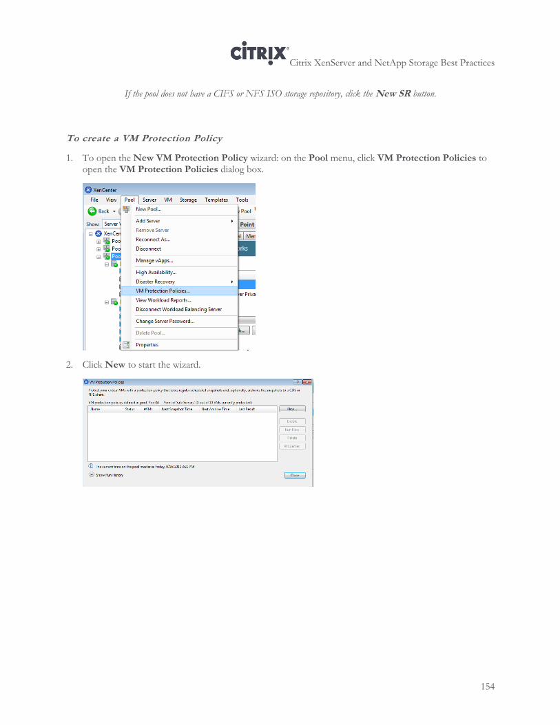
Citrix XenServer and NetApp Storage Best Practices
154
If the pool does not have a CIFS or NFS ISO storage repository, click the New SR button.
To create a VM Protection Policy
1. To open the New VM Protection Policy wizard: on the Pool menu, click VM Protection Policies to open the VM Protection Policies dialog box.
2. Click New to start the wizard.
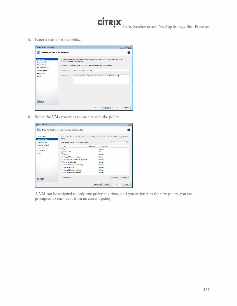
Citrix XenServer and NetApp Storage Best Practices
155
5. Enter a name for the policy.
6. Select the VMs you want to protect with the policy.
A VM can be assigned to only one policy at a time, so if you assign it to the new policy, you are prompted to remove it from its current policy.
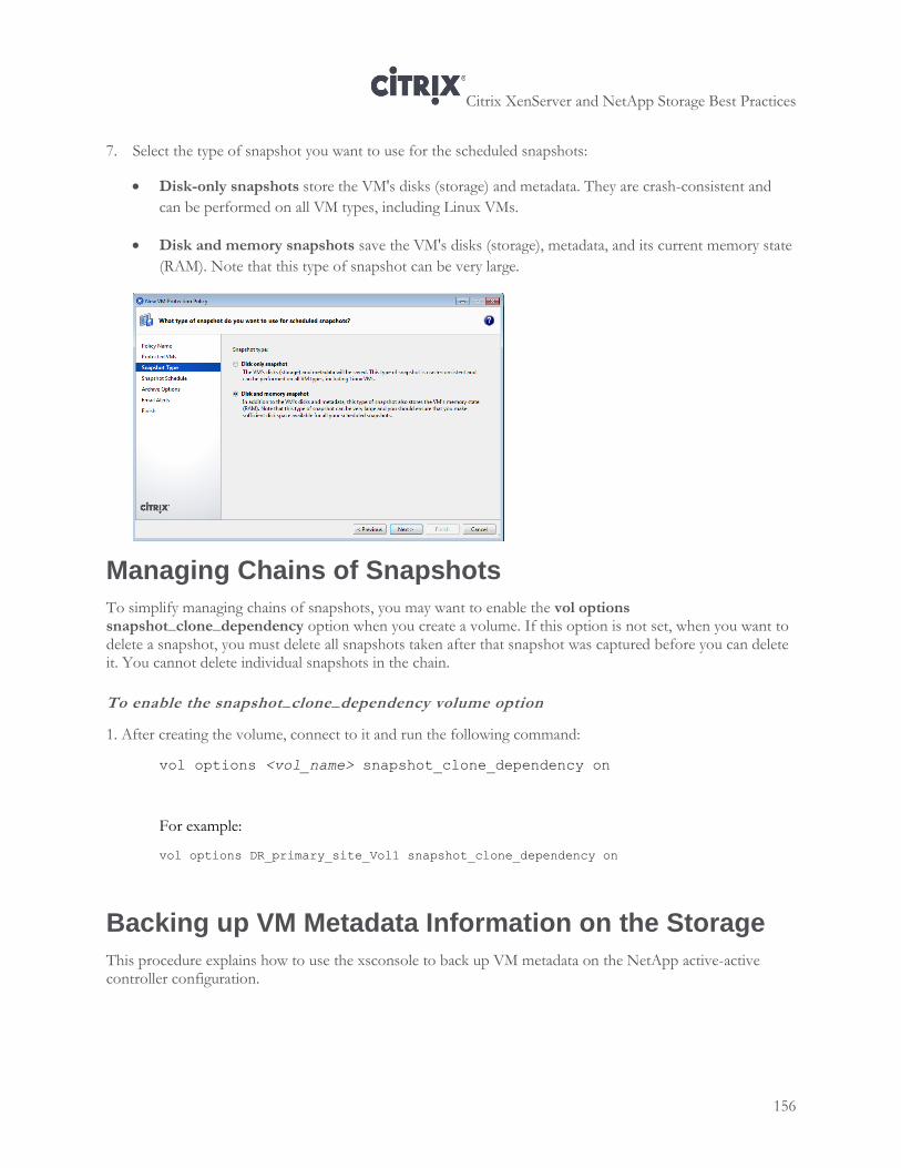
Citrix XenServer and NetApp Storage Best Practices
156
7. Select the type of snapshot you want to use for the scheduled snapshots:
Disk-only snapshots store the VM's disks (storage) and metadata. They are crash-consistent and
can be performed on all VM types, including Linux VMs.
Disk and memory snapshots save the VM's disks (storage), metadata, and its current memory state
(RAM). Note that this type of snapshot can be very large.
Managing Chains of Snapshots
To simplify managing chains of snapshots, you may want to enable the vol options snapshot_clone_dependency option when you create a volume. If this option is not set, when you want to delete a snapshot, you must delete all snapshots taken after that snapshot was captured before you can delete it. You cannot delete individual snapshots in the chain.
To enable the snapshot_clone_dependency volume option
1. After creating the volume, connect to it and run the following command:
vol options <vol_name> snapshot_clone_dependency on
For example:
vol options DR_primary_site_Vol1 snapshot_clone_dependency on
Backing up VM Metadata Information on the Storage
This procedure explains how to use the xsconsole to back up VM metadata on the NetApp active-active controller configuration.
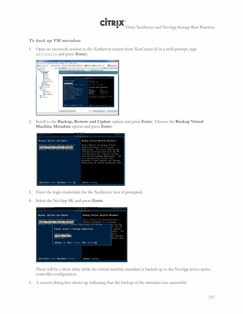
Citrix XenServer and NetApp Storage Best Practices
157
To back up VM metadata
1. Open an xsconsole session to the XenServer master from XenCenter (if in a shell prompt, type xsconsole and press Enter).
2. Scroll to the Backup, Restore and Update option and press Enter. Choose the Backup Virtual Machine Metadata option and press Enter.
3. Enter the login credentials for the XenServer host if prompted.
4. Select the NetApp SR, and press Enter.
There will be a short delay while the virtual machine metadata is backed up to the NetApp active-active controller configuration.
5. A success dialog box shows up indicating that the backup of the metadata was successful.
Citrix XenServer and NetApp Storage Best Practices
158
Backing up Storage Repositories (NetApp SnapMirror)
You can use the NetApp SnapMirror® technology to back up the volumes that make up the SR. SnapMirror creates snapshots to copy data from a source volume to a backup (partner) volume, often for disaster-recovery purposes.
Before SnapMirror can copy data, however, you must create a link between the data source and its destination.
When SnapMirror replicates data on the back-up volume, it does at almost the same time as the data is written to the source volume. For more information on use of SnapMirror, see the SnapMirror Administration guide at http://support.netapp.com. See also the Data ONTAP 8.0 7-Mode Storage Efficiency Management Guide.
Some considerations when using SnapMirror:
1. For SnapMirror volume replication, the destination storage system must use a version of Data ONTAP that is the same as or later than that of the SnapMirror source storage system. For volume SnapMirror to support replication for the purpose of disaster recovery, both the source and destination storage systems must use the same version of Data ONTAP.
2. To optimize performance, stagger Snapshot copy update schedules so that SnapMirror activity does not begin or end at the exact minute a snap sched command operation attempts to create a Snapshot copy. If the SnapMirror feature is scheduled to perform Snapshot management at the same time as a snap sched activity, the Snapshot management operations scheduled using the snap sched command might fail with syslog messages: Skipping creation of hourly snapshot and Snapshot already exists.
3. For optimum SnapMirror volume replication performance, ensure that the SnapMirror source volume and destination volume contain disks of the same size.
4. To achieve maximum space savings on the destination volume, scan the entire file system to recreate the deduplication metadata for the destination volume. Use the sis start -s command to do so. Note: The destination volume is accessible for read-write operations when the deduplication scan is in progress. The sis start command, without the -s option, has the potential for space savings on the destination volume is reduced because only the new data written to the volume will be scanned for deduplication. For more information about deduplication, see “Reclaiming Space with NetApp Deduplication” on page 25.
Note: Starting with Data ONTAP 8.0.1 7-Mode, FlexClone volumes can be replicated using volume SnapMirror without the need for additional capacity on the destination system as long as the parent of the FlexClone volume is also replicated. Please consult TR-3446: SnapMirror Async Overview and Best Practices Guide available at http://www.netapp.com.
5. For Firewall setting, allow a range of TCP ports from 10565 to 10569.
The following illustration provides an example of replication between the primary and recovery site.
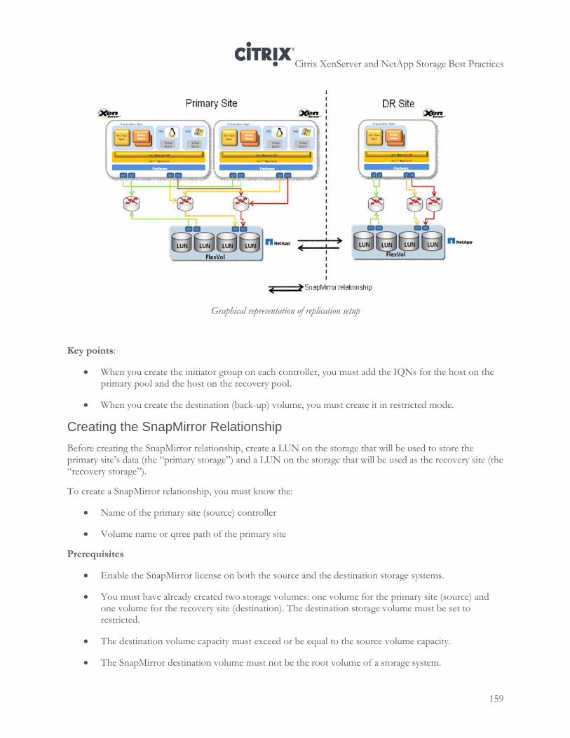
Citrix XenServer and NetApp Storage Best Practices
159
Graphical representation of replication setup
Key points:
When you create the initiator group on each controller, you must add the IQNs for the host on the primary pool and the host on the recovery pool.
When you create the destination (back-up) volume, you must create it in restricted mode.
Creating the SnapMirror Relationship
Before creating the SnapMirror relationship, create a LUN on the storage that will be used to store the primary site’s data (the “primary storage”) and a LUN on the storage that will be used as the recovery site (the “recovery storage”).
To create a SnapMirror relationship, you must know the:
Name of the primary site (source) controller
Volume name or qtree path of the primary site
Prerequisites
Enable the SnapMirror license on both the source and the destination storage systems.
You must have already created two storage volumes: one volume for the primary site (source) and one volume for the recovery site (destination). The destination storage volume must be set to restricted.
The destination volume capacity must exceed or be equal to the source volume capacity.
The SnapMirror destination volume must not be the root volume of a storage system.
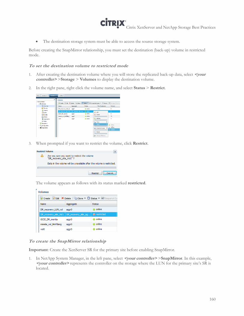
Citrix XenServer and NetApp Storage Best Practices
160
The destination storage system must be able to access the source storage system.
Before creating the SnapMirror relationship, you must set the destination (back-up) volume in restricted mode.
To set the destination volume to restricted mode
1. After creating the destination volume where you will store the replicated back-up data, select <your controller> >Storage > Volumes to display the destination volume.
2. In the right pane, right click the volume name, and select Status > Restrict.
3. When prompted if you want to restrict the volume, click Restrict.
The volume appears as follows with its status marked restricted.
To create the SnapMirror relationship
Important: Create the XenServer SR for the primary site before enabling SnapMirror.
1. In NetApp System Manager, in the left pane, select <your controller> >SnapMirror. In this example, <your controller> represents the controller on the storage where the LUN for the primary site’s SR is located.
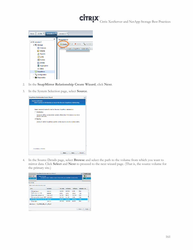
Citrix XenServer and NetApp Storage Best Practices
161
2. In the SnapMirror Relationship Create Wizard, click Next.
3. In the System Selection page, select Source.
4. In the Source Details page, select Browse and select the path to the volume from which you want to mirror data. Click Select and Next to proceed to the next wizard page. (That is, the source volume for the primary site.)
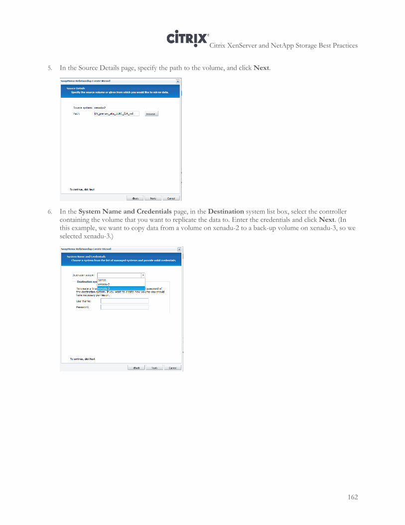
Citrix XenServer and NetApp Storage Best Practices
162
5. In the Source Details page, specify the path to the volume, and click Next.
6. In the System Name and Credentials page, in the Destination system list box, select the controller containing the volume that you want to replicate the data to. Enter the credentials and click Next. (In this example, we want to copy data from a volume on xenadu-2 to a back-up volume on xenadu-3, so we selected xenadu-3.)
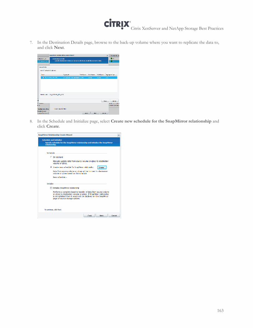
Citrix XenServer and NetApp Storage Best Practices
163
7. In the Destination Details page, browse to the back-up volume where you want to replicate the data to, and click Next.
8. In the Schedule and Initialize page, select Create new schedule for the SnapMirror relationship and click Create.
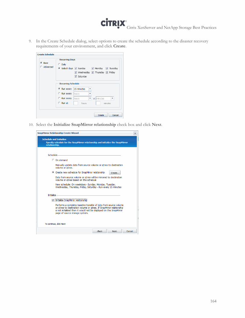
Citrix XenServer and NetApp Storage Best Practices
164
9. In the Create Schedule dialog, select options to create the schedule according to the disaster recovery requirements of your environment, and click Create.
10. Select the Initialize SnapMirror relationship check box and click Next.
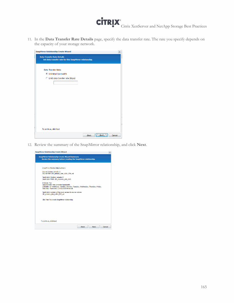
Citrix XenServer and NetApp Storage Best Practices
165
11. In the Data Transfer Rate Details page, specify the data transfer rate. The rate you specify depends on the capacity of your storage network.
12. Review the summary of the SnapMirror relationship, and click Next.
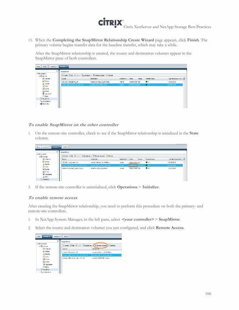
Citrix XenServer and NetApp Storage Best Practices
166
13. When the Completing the SnapMirror Relationship Create Wizard page appears, click Finish. The primary volume begins transfer data for the baseline transfer, which may take a while.
After the SnapMirror relationship is created, the source and destination volumes appear in the SnapMirror pane of both controllers.
To enable SnapMirror on the other controller
1. On the remote-site controller, check to see if the SnapMirror relationship is initialized in the State column.
2. If the remote-site controller is uninitialized, click Operations > Initialize.
To enable remote access
After creating the SnapMirror relationship, you need to perform this procedure on both the primary- and remote-site controllers.
1. In NetApp System Manager, in the left pane, select <your controller> > SnapMirror.
2. Select the source and destination volumes you just configured, and click Remote Access.
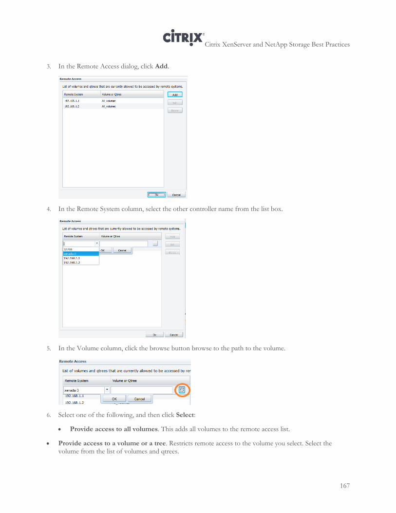
Citrix XenServer and NetApp Storage Best Practices
167
3. In the Remote Access dialog, click Add.
4. In the Remote System column, select the other controller name from the list box.
5. In the Volume column, click the browse button browse to the path to the volume.
6. Select one of the following, and then click Select:
Provide access to all volumes. This adds all volumes to the remote access list.
Provide access to a volume or a tree. Restricts remote access to the volume you select. Select the volume from the list of volumes and qtrees.
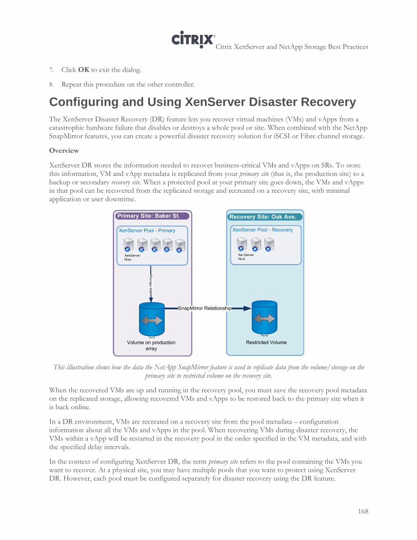
Citrix XenServer and NetApp Storage Best Practices
168
7. Click OK to exit the dialog.
8. Repeat this procedure on the other controller.
Configuring and Using XenServer Disaster Recovery
The XenServer Disaster Recovery (DR) feature lets you recover virtual machines (VMs) and vApps from a catastrophic hardware failure that disables or destroys a whole pool or site. When combined with the NetApp SnapMirror features, you can create a powerful disaster recovery solution for iSCSI or Fibre channel storage.
Overview
XenServer DR stores the information needed to recover business-critical VMs and vApps on SRs. To store this information, VM and vApp metadata is replicated from your primary site (that is, the production site) to a backup or secondary recovery site. When a protected pool at your primary site goes down, the VMs and vApps in that pool can be recovered from the replicated storage and recreated on a recovery site, with minimal application or user downtime.
This illustration shows how the data the NetApp SnapMirror feature is used to replicate data from the volume/storage on the primary site to restricted volume on the recovery site.
When the recovered VMs are up and running in the recovery pool, you must save the recovery pool metadata on the replicated storage, allowing recovered VMs and vApps to be restored back to the primary site when it is back online.
In a DR environment, VMs are recreated on a recovery site from the pool metadata – configuration information about all the VMs and vApps in the pool. When recovering VMs during disaster recovery, the VMs within a vApp will be restarted in the recovery pool in the order specified in the VM metadata, and with the specified delay intervals.
In the context of configuring XenServer DR, the term primary site refers to the pool containing the VMs you want to recover. At a physical site, you may have multiple pools that you want to protect using XenServer DR. However, each pool must be configured separately for disaster recovery using the DR feature.
Citrix XenServer and NetApp Storage Best Practices
169
The term primary pool refers to the pool on the primary site.
The term recovery pool refers to the backup pool on the recovery site.
Note: To configure DR, you must be logged in to the XenServer 6.0 pool as root or have a Role Based Access Control (RBAC) of Pool Operator or higher. The XenServer Disaster Recovery feature is available in Citrix XenServer 6.0 Platinum Edition. To learn more about the features available in different XenServer Editions, click here.
Understanding the Disaster Recovery Lifecycle
Disaster Recovery lifecycle comprises the following main phases:
1. DR Configuration on the Primary Site. Setting up the XenServer DR feature and its supporting requirements, such as the SnapMirror relationship.
2. Failover. After a disaster event at the primary site, you must manually fail over to the recovery site. The VMs will be recreated at the recovery site and your users will work from those VMs at this site until the disaster event is over.
3. DR Configuration on the Recovery Site. Setting up the XenServer DR feature and its supporting requirements on the recovery site, so that you can fail back.
4. Failback. After the disaster event is over and the primary site is back online, you can restore your environment to the primary site and its associated storage.
Each of these phases of the lifecycle requires specific procedures, which are outlined in the corresponding sections in this chapter.
Planning XenServer DR Configuration
To set up a XenServer DR solution, the storage used for both the pool metadata and the VM’s virtual disks must be replicated from your primary (production) environment to a recovery environment. Storage replication is done in NetApp by using the SnapMirror feature.
Configuration Process
When you want to configure a disaster recovery solution using NetApp and XenServer the overall process is as follows:
1. Plan where you want to locate your primary and recovery site, including the storage you want to use. Ideally, you should know the number of VMs you want to recover in a DR event or ensure you will have enough space on the recovery site.
When determining how many hosts you will need in the recovery pool, do so based on the number that would be required to run the VMs you want to recover from the primary-site pool (that is, the VMs you consider to be mission critical).
2. Create a volume and LUN on the storage where you want to store the primary site’s data.
3. Create a volume on the storage where you want to replicate the primary site’s data. That is, create the volume on the recovery storage at the recovery site.
4. Configure the SR for your primary site by following one of the standard SR creation processes in the previous chapters of this guide.
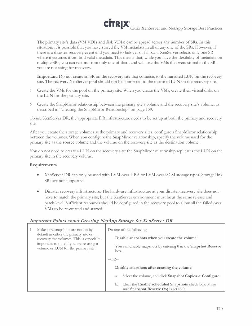
Citrix XenServer and NetApp Storage Best Practices
170
The primary site’s data (VM VDIs and disk VDIs) can be spread across any number of SRs. In this situation, it is possible that you have stored the VM metadata in all or any one of the SRs. However, if there is a disaster-recovery event and you need to failover or failback, XenServer selects only one SR where it assumes it can find valid metadata. This means that, while you have the flexibility of metadata on multiple SRs, you can restore from only one of them and will lose the VMs that were stored in the SRs you are not using for recovery.
Important: Do not create an SR on the recovery site that connects to the mirrored LUN on the recovery site. The recovery XenServer pool should not be connected to the mirrored LUN on the recovery site.
5. Create the VMs for the pool on the primary site. When you create the VMs, create their virtual disks on the LUN for the primary site.
6. Create the SnapMirror relationship between the primary site’s volume and the recovery site’s volume, as described in “Creating the SnapMirror Relationship” on page 159.
To use XenServer DR, the appropriate DR infrastructure needs to be set up at both the primary and recovery site.
After you create the storage volumes at the primary and recovery sites, configure a SnapMirror relationship between the volumes. When you configure the SnapMirror relationship, specify the volume used for the primary site as the source volume and the volume on the recovery site as the destination volume.
You do not need to create a LUN on the recovery site: the SnapMirror relationship replicates the LUN on the primary site in the recovery volume.
Requirements
XenServer DR can only be used with LVM over HBA or LVM over iSCSI storage types. StorageLink
SRs are not supported.
Disaster recovery infrastructure. The hardware infrastructure at your disaster-recovery site does not
have to match the primary site, but the XenServer environment must be at the same release and
patch level. Sufficient resources should be configured in the recovery pool to allow all the failed over
VMs to be re-created and started.
Important Points about Creating NetApp Storage for XenServer DR
1. Make sure snapshots are not on by default in either the primary site or recovery site volumes. This is especially important to note if you are re-using a volume or LUN for the primary site.
Do one of the following:
Disable snapshots when you create the volume:
You can disable snapshots by entering 0 in the Snapshot Reserve box.
--OR--
Disable snapshots after creating the volume:
a. Select the volume, and click Snapshot Copies > Configure.
b. Clear the Enable scheduled Snapshots check box. Make sure Snapshot Reserve (%) is set to 0.
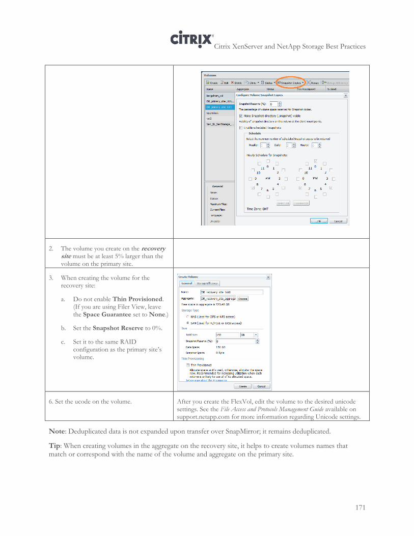
Citrix XenServer and NetApp Storage Best Practices
171
2. The volume you create on the recovery site must be at least 5% larger than the volume on the primary site.
3. When creating the volume for the recovery site:
a. Do not enable Thin Provisioned. (If you are using Filer View, leave the Space Guarantee set to None.)
b. Set the Snapshot Reserve to 0%.
c. Set it to the same RAID configuration as the primary site’s volume.
6. Set the ucode on the volume.
After you create the FlexVol, edit the volume to the desired unicode settings. See the File Access and Protocols Management Guide available on support.netapp.com for more information regarding Unicode settings.
Note: Deduplicated data is not expanded upon transfer over SnapMirror; it remains deduplicated.
Tip: When creating volumes in the aggregate on the recovery site, it helps to create volumes names that match or correspond with the name of the volume and aggregate on the primary site.
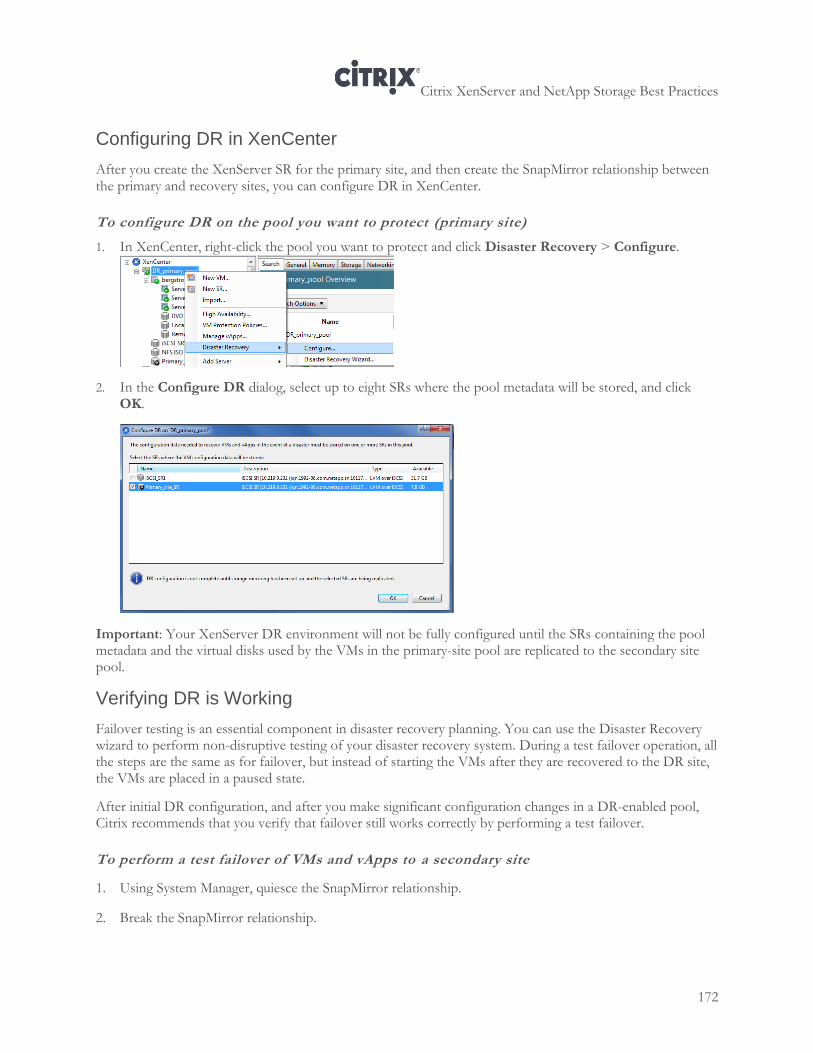
Citrix XenServer and NetApp Storage Best Practices
172
Configuring DR in XenCenter
After you create the XenServer SR for the primary site, and then create the SnapMirror relationship between the primary and recovery sites, you can configure DR in XenCenter.
To configure DR on the pool you want to protect (primary site)
1. In XenCenter, right-click the pool you want to protect and click Disaster Recovery > Configure.
2. In the Configure DR dialog, select up to eight SRs where the pool metadata will be stored, and click OK.
Important: Your XenServer DR environment will not be fully configured until the SRs containing the pool metadata and the virtual disks used by the VMs in the primary-site pool are replicated to the secondary site pool.
Verifying DR is Working
Failover testing is an essential component in disaster recovery planning. You can use the Disaster Recovery wizard to perform non-disruptive testing of your disaster recovery system. During a test failover operation, all the steps are the same as for failover, but instead of starting the VMs after they are recovered to the DR site, the VMs are placed in a paused state.
After initial DR configuration, and after you make significant configuration changes in a DR-enabled pool, Citrix recommends that you verify that failover still works correctly by performing a test failover.
To perform a test failover of VMs and vApps to a secondary site
1. Using System Manager, quiesce the SnapMirror relationship.
2. Break the SnapMirror relationship.
Citrix XenServer and NetApp Storage Best Practices
173
3. In XenCenter, select the recovery pool, and on the Pool menu, click Disaster Recovery to open the Disaster Recovery wizard.
4. Select Test Failover and then click Next.
Note: If you use Fibre Channel shared storage with LUN mirroring to replicate the data to the secondary site, before you attempt to recover data, break the SnapMirror relationship so that the recovery site has Read/Write access.
5. Select the storage repositories (SRs) containing the pool metadata for the VMs and vApps that you want to recover.
By default, the list on this wizard page shows all SRs that are currently attached within the pool. To scan for more SRs, choose Find Storage Repositories and then select the storage type to scan for:
To scan for all the available Hardware HBA SRs, select Find Hardware HBA SRs.
To scan for software iSCSI SRs, select Find Software iSCSI SRs and then enter the target host, IQN and LUN details in the dialog box.
When you have selected the required SRs in the wizard, click Next to continue.
6. Select the VMs and vApps that you wish to recover then click Next to progress to the next wizard page and begin failover prechecks.
7. Before beginning the test failover process, the wizard performs a number of pre-checks, for example, to ensure that all the storage required by the selected VMs and vApps is available.
a. Check that storage is available. If any storage is missing, you can click Attach SR on this page to find and attach the relevant SR.
b. Check that HA is not enabled on the target recovery pool. To avoid having the same VMs running on both the primary and recovery pools, HA must be disabled on the recovery pool to ensure HA does not automatically start the recovered VMs and vApps after recovery. To disable HA on the recovery pool, you can simply click Disable HA on this page. (If HA is disabled at this point, it will be enabled again automatically at the end of the test failover process.)
8. Resolve any issues on the pre-checks page, and then click Failover to begin the test failover.
A progress page is displayed showing whether recovery was successful for each VM and vApp.
Failover may take some time depending on the number of VMs and vApps you are recovering, as the metadata for the VMs and vApps are recovered from the replicated storage, the VMs and vApps are re-created in the recovery pool, the SRs containing the virtual disks are attached to the re-created VMs.
The recovered VMs are placed in a paused state: they will not be started up on the secondary site during a test failover.
9. After you are satisfied that the test failover was performed successfully, click Next in the wizard to have the wizard clean up on the DR site:
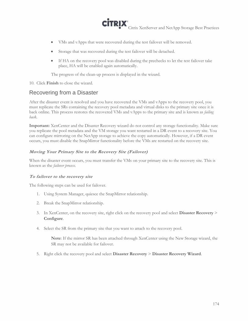
Citrix XenServer and NetApp Storage Best Practices
174
VMs and vApps that were recovered during the test failover will be removed.
Storage that was recovered during the test failover will be detached.
If HA on the recovery pool was disabled during the prechecks to let the test failover take place, HA will be enabled again automatically.
The progress of the clean-up process is displayed in the wizard.
10. Click Finish to close the wizard.
Recovering from a Disaster
After the disaster event is resolved and you have recovered the VMs and vApps to the recovery pool, you must replicate the SRs containing the recovery pool metadata and virtual disks to the primary site once it is back online. This process restores the recovered VMs and vApps to the primary site and is known as failing back.
Important: XenCenter and the Disaster Recovery wizard do not control any storage functionality. Make sure you replicate the pool metadata and the VM storage you want restarted in a DR event to a recovery site. You can configure mirroring on the NetApp storage to achieve the copy automatically. However, if a DR event occurs, you must disable the SnapMirror functionality before the VMs are restarted on the recovery site.
Moving Your Primary Site to the Recovery Site (Failover)
When the disaster event occurs, you must transfer the VMs on your primary site to the recovery site. This is known as the failover process.
To failover to the recovery site
The following steps can be used for failover.
1. Using System Manager, quiesce the SnapMirror relationship.
2. Break the SnapMirror relationship.
3. In XenCenter, on the recovery site, right click on the recovery pool and select Disaster Recovery >
Configure.
4. Select the SR from the primary site that you want to attach to the recovery pool.
Note: If the mirror SR has been attached through XenCenter using the New Storage wizard, the
SR may not be available for failover.
5. Right click the recovery pool and select Disaster Recovery > Disaster Recovery Wizard.
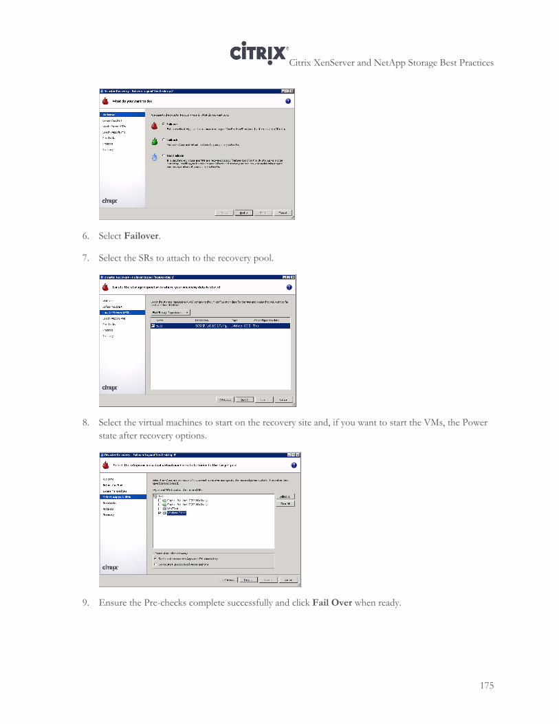
Citrix XenServer and NetApp Storage Best Practices
175
6. Select Failover.
7. Select the SRs to attach to the recovery pool.
8. Select the virtual machines to start on the recovery site and, if you want to start the VMs, the Power
state after recovery options.
9. Ensure the Pre-checks complete successfully and click Fail Over when ready.
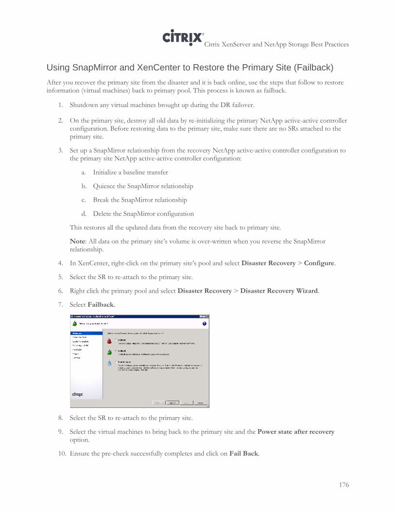
Citrix XenServer and NetApp Storage Best Practices
176
Using SnapMirror and XenCenter to Restore the Primary Site (Failback)
After you recover the primary site from the disaster and it is back online, use the steps that follow to restore information (virtual machines) back to primary pool. This process is known as failback.
1. Shutdown any virtual machines brought up during the DR failover.
2. On the primary site, destroy all old data by re-initializing the primary NetApp active-active controller configuration. Before restoring data to the primary site, make sure there are no SRs attached to the primary site.
3. Set up a SnapMirror relationship from the recovery NetApp active-active controller configuration to the primary site NetApp active-active controller configuration:
a. Initialize a baseline transfer
b. Quiesce the SnapMirror relationship
c. Break the SnapMirror relationship
d. Delete the SnapMirror configuration
This restores all the updated data from the recovery site back to primary site.
Note: All data on the primary site’s volume is over-written when you reverse the SnapMirror relationship.
4. In XenCenter, right-click on the primary site’s pool and select Disaster Recovery > Configure.
5. Select the SR to re-attach to the primary site.
6. Right click the primary pool and select Disaster Recovery > Disaster Recovery Wizard.
7. Select Failback.
8. Select the SR to re-attach to the primary site.
9. Select the virtual machines to bring back to the primary site and the Power state after recovery option.
10. Ensure the pre-check successfully completes and click on Fail Back.

Citrix XenServer and NetApp Storage Best Practices
177
11. Once the primary site is up and running, delete the SnapMirror configuration on the recovery site NetApp active-active controller configuration
12. Repeat the steps in creating the SnapMirror relationship to set up replication between the primary site and DR site.
Citrix XenServer and NetApp Storage Best Practices
178
Appendix A: Fixing Misaligned Windows Guest Operating System
This appendix provides information about fixing misaligned Windows guest operating systems, including the following:
An overview of the issue
An explanation of how to resolve the issue
For more information about fixing misaligned Windows guest operating systems, such as Windows XP, Windows Server 2003 and some version of Linux, see TR-3747 Best Practice for File System Alignment in Virtual Environments.
Overview
Disks use geometry to identify themselves and their characteristics to the upper layer operating system. The upper-layer operating system uses the disk geometry information to calculate the size of the disk and partition the disk into predetermined addressable blocks. Just as with physical disks, logical disks (LUNs) report disk geometry to the host so that it can calculate space and partition the LUN into addressable blocks.
NetApp uses 4KB blocks (4 x 1,024 = 4,096 bytes) as its basic storage building block. Writes can consume no less than a single 4KB block and can consume many 4KB blocks depending on the size of the write operation. Files that are smaller than 4KB are actually stored in the inode that contains their metadata. When a LUN is created in Data ONTAP, a certain amount of space is carved out of the disk in the form of 4KB blocks. These are then reported to the host OS with a specified geometry, depending on the LUN type selected. The host OS then takes the presented LUN and partitions it appropriately.
The problem of misaligned LUN I/O occurs when the partitioning scheme used by the host OS does not match the block boundaries inside the LUN. Note: This problem is not peculiar to NetApp. All SAN vendors have the potential to experience misalignment issues. Misalignment issues can be caused because the partition size of the blocks in the host OS use something other than 4KB blocks. Misalignment issues can be caused if the host OS imposes an offset that has not been compensated for. NetApp compensates for offsets by identifying the OS and then adjusting the offset. This is done during LUN creation when the user enters the LUN type.
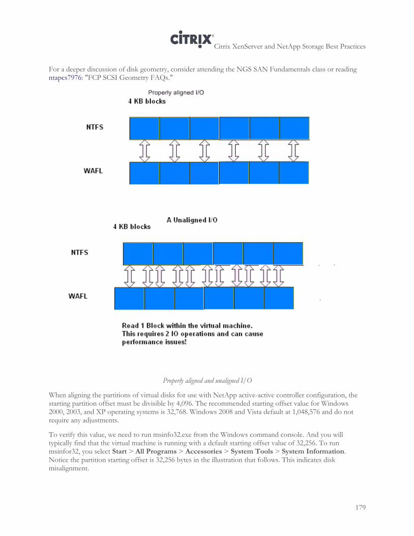
Citrix XenServer and NetApp Storage Best Practices
179
For a deeper discussion of disk geometry, consider attending the NGS SAN Fundamentals class or reading ntapcs7976: "FCP SCSI Geometry FAQs."
Properly aligned and unaligned I/O
When aligning the partitions of virtual disks for use with NetApp active-active controller configuration, the starting partition offset must be divisible by 4,096. The recommended starting offset value for Windows 2000, 2003, and XP operating systems is 32,768. Windows 2008 and Vista default at 1,048,576 and do not require any adjustments.
To verify this value, we need to run msinfo32.exe from the Windows command console. And you will typically find that the virtual machine is running with a default starting offset value of 32,256. To run msinfor32, you select Start > All Programs > Accessories > System Tools > System Information. Notice the partition starting offset is 32,256 bytes in the illustration that follows. This indicates disk misalignment.
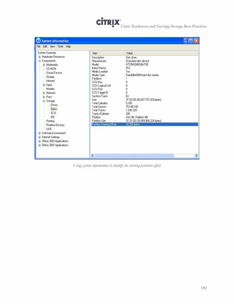
Citrix XenServer and NetApp Storage Best Practices
180
Using system information to identify the starting partition offset.
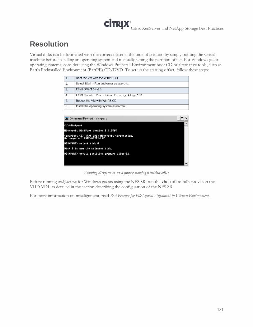
Citrix XenServer and NetApp Storage Best Practices
181
Resolution
Virtual disks can be formatted with the correct offset at the time of creation by simply booting the virtual machine before installing an operating system and manually setting the partition offset. For Windows guest operating systems, consider using the Windows Preinstall Environment boot CD or alternative tools, such as Bart's Preinstalled Environment (BartPE) CD/DVD. To set up the starting offset, follow these steps:
Running diskpart to set a proper starting partition offset.
Before running diskpart.exe for Windows guests using the NFS SR, run the vhd-util to fully provision the VHD VDI, as detailed in the section describing the configuration of the NFS SR.
For more information on misalignment, read Best Practice for File System Alignment in Virtual Environment.
Citrix XenServer and NetApp Storage Best Practices
182
Appendix B: Authentication Considerations
This appendix provides information about how to configure administrator access to the NetApp storage, including:
How to map Windows domain\administrator privileges to UNIX root privileges in environments that use multiple protocols
Equating Windows 'Domain\Administrator' privileges to UNIX 'root'
To let XenServer administrators log in to the device with root privileges and create the FlexVol volumes for the NetApp Storage Repository, use the following procedure as a guideline.
To equate Windows domain administrator privileges to UNIX root 1. To equate Windows 'Domain\Administrator' privileges to UNIX 'root' in a multi-protocol environment,
on the device enter:
device> options wafl.nt_admin_priv_map_to_root on
2. Authorizing a Unix User Account to Login As Root on the Device
Data ONTAP uses the /etc/usermap.cfg file to map user names. In its simplest form, each /etc/usermap.cfg entry contains a pair of names: the Windows name and the UNIX name. Data ONTAP can translate the Windows name to the UNIX name or vice versa.
When a connection is started, if the /etc/usermap.cfg file is missing, a default file is created. It contains commented-out sample map entries that are useful for improving security. When Data ONTAP receives a connection request from a user, it searches the /etc/usermap.cfg file to see whether an entry matches the user’s Windows domain name and user name. If an entry is found, Data ONTAP uses the UNIX name specified in the entry to look up the UID and GID from the UNIX password database. If the UNIX name is a null string, Data ONTAP denies access to the user.
If an entry is not found, Data ONTAP converts the Windows name to lowercase and considers the UNIX name to be the same as the Windows name. Data ONTAP uses this UNIX name to look up the UID and GID from the UNIX password database. Data ONTAP
Citrix XenServer and NetApp Storage Best Practices
183
http://www.citrix.com/English/partners/partner.asp?partnerID=950197scans the file sequentially. It uses the first matching entry for mapping.
For information about character coding of the /etc/usermap.cfg file, see the information about the contents of the /etc directory in the Storage Management Guide.
Specify each entry using the following format: [IP_qualifier:] Windows_name [direction] [IP_qualifier:]
UNIX_name
where IP_qualifier field is an IP address that qualifies the user name by narrowing the match. Windows_name field consists of a Windows domain name, which is optional, and a Windows user name. Direction field indicates the direction of the mapping. UNIX_name field is a UNIX name in the UNIX password database.
You can embed comments in the file by beginning the comment lines with #. Comments at the end of an entry are also allowed if preceded by #. Blank lines are ignored.
The way in which Data ONTAP interprets a domain name in the /etc/usermap.cfg file that contains a dot depends on whether storage system is in a Windows NT domain or a Windows Active Directory domain. Follow some guidelines to keep entries simple and easy to understand, and add several entries to the /etc/usermap.cfg file to prevent unauthorized users from accessing the storage system.
Citrix XenServer and NetApp Storage Best Practices
184
Appendix C: Enhancements in Data ONTAP
Data ONTAP 8.0 7-Mode introduces 64-bit aggregates which are no longer limited to 16TB. Consult TR-3786: A Thorough Introduction to 64-Bit Aggregates for complete details and sizing information, available at http://support.netapp.com.
Data ONTAP 8.0.1 7-Mode FlexClone volumes can be replicated using volume SnapMirror without the need for additional capacity on the destination system as long as the parent of the FlexClone volume is also replicated. Please consult TR-3446: SnapMirror Async Overview and Best Practices Guide available at http://support.netapp.com.
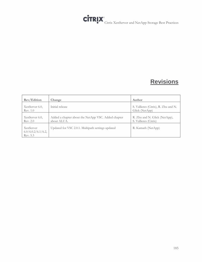
Citrix XenServer and NetApp Storage Best Practices
185
Revisions
Rev/Edition Change Author
XenServer 6.0, Rev. 1.0
Initial release S. Vallieres (Citrix), R. Zhu and N. Glick (NetApp)
XenServer 6.0, Rev. 2.0
Added a chapter about the NetApp VSC. Added chapter about ALUA.
R. Zhu and N. Glick (NetApp), S. Vallieres (Citrix)
XenServer 6.0/6.0.2/6.1/6.2, Rev. 5.3
Updated for VSC 2.0.1. Multipath settings updated R. Kamath (NetApp)
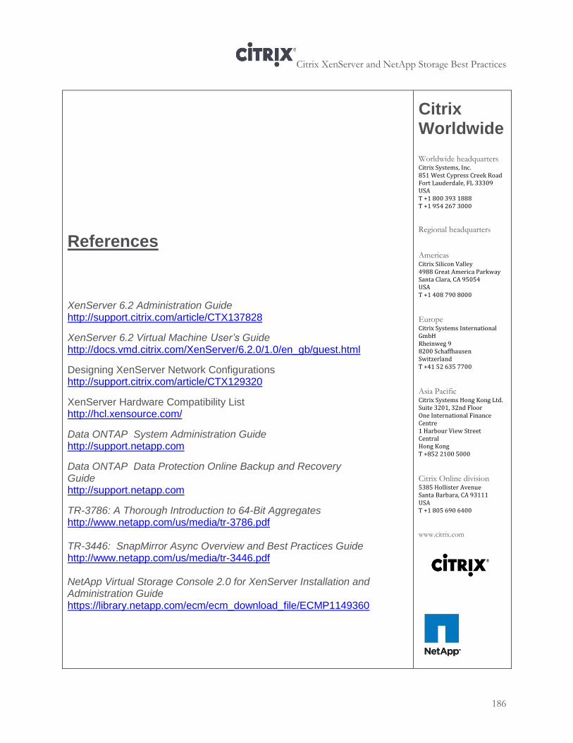
Citrix XenServer and NetApp Storage Best Practices
186
References
XenServer 6.2 Administration Guide http://support.citrix.com/article/CTX137828
XenServer 6.2 Virtual Machine User’s Guide
http://docs.vmd.citrix.com/XenServer/6.2.0/1.0/en_gb/guest.html
Designing XenServer Network Configurations http://support.citrix.com/article/CTX129320
XenServer Hardware Compatibility List http://hcl.xensource.com/
Data ONTAP System Administration Guide http://support.netapp.com
Data ONTAP Data Protection Online Backup and Recovery Guide http://support.netapp.com
TR-3786: A Thorough Introduction to 64-Bit Aggregates http://www.netapp.com/us/media/tr-3786.pdf TR-3446: SnapMirror Async Overview and Best Practices Guide http://www.netapp.com/us/media/tr-3446.pdf NetApp Virtual Storage Console 2.0 for XenServer Installation and Administration Guide https://library.netapp.com/ecm/ecm_download_file/ECMP1149360
Citrix Worldwide
Worldwide headquarters Citrix Systems, Inc. 851 West Cypress Creek Road Fort Lauderdale, FL 33309 USA T +1 800 393 1888 T +1 954 267 3000
Regional headquarters
Americas Citrix Silicon Valley 4988 Great America Parkway Santa Clara, CA 95054 USA T +1 408 790 8000
Europe Citrix Systems International GmbH Rheinweg 9 8200 Schaffhausen Switzerland T +41 52 635 7700
Asia Pacific Citrix Systems Hong Kong Ltd. Suite 3201, 32nd Floor One International Finance Centre 1 Harbour View Street Central Hong Kong T +852 2100 5000
Citrix Online division 5385 Hollister Avenue Santa Barbara, CA 93111 USA T +1 805 690 6400
www.citrix.com
Citrix XenServer and NetApp Storage Best Practices
187
Copyright © 2014 Citrix Systems. Inc. All Rights Reserved. Version: 5.3
About NetApp, Inc.
NetApp creates innovative storage and data management solutions that accelerate business breakthroughs and deliver outstanding cost efficiency. Discover our passion for helping companies around the world go further, faster at www.netapp.com.
About Citrix Systems, Inc. Citrix Systems, Inc. (NASDAQ: CTXS) is the global leader in access infrastructure and the most trusted name in secure access. More than 200,000 organizations around the world use the Citrix Access Platform to provide secure, well-managed access to business information wherever it lives —on demand. Citrix customers include 100 percent of the Fortune 100 companies, 99 percent of the Fortune 500, and 97 percent of the Fortune Global 500, in addition to hundreds of thousands of smaller businesses and individuals. Based in Fort Lauderdale, Florida, Citrix has offices in 22 countries and approximately 6,200 channel and alliance partners in more than 100 countries. Annual revenue in 2010 was $1.87 billion.
Disclaimers
This document is furnished "AS IS." Citrix, Inc. disclaims all warranties regarding the contents of this document, including, but not limited to, implied warranties of merchantability and fitness for any particular purpose. This document may contain technical or other inaccuracies or typographical errors. Citrix, Inc. reserves the right to revise the information in this document at any time without notice. This document and the software described in this document constitute confidential information of Citrix, Inc. and its licensors, and are furnished under a license from Citrix, Inc. Citrix Systems, Inc., the Citrix logo, Citrix XenServer and Citrix XenCenter, are trademarks of Citrix Systems, Inc. and/or one or more of its subsidiaries, and may be registered in the United States Patent and Trademark Office and in other countries. All other trademarks and registered trademarks are property of their respective owners. Trademarks
Data ONTAP, FlexClone, FlexVol, OnCommand, RAID-DP, Snapshot, SnapMirror, and SnapVault are trademarks or registered trademarks of NetApp, Inc. in the United States and/or other countries. Citrix, XenServer, and XenCenter are registered trademarks of Citrix Systems, Inc. All other trademarks are the property of their respective owners.