Embed Size (px)
Citation preview
FACULTY OF CIVIL AND INDUSTRIAL ENGINEERING
Master Degree in Transport Systems Engineering
CITYFLO 350 Signaling System Interface between ATP Telegrams and Brake curve
Istanbul new Metro Line Study case
Candidate:
Houshang Kheiri Sadigh
Supervisor: External Supervisor:
Prof. Stefano Ricci Engineer. Fabrizio Vagnucci
Academic Year: 2017/2018
The present thesis was written within an Internship activity
in collaboration with:
BOMBARDIER Transportation
Abstract
Public transport has been discussing for years and its importance is perceptible for anyone, as the most powerful solution for the congestion, public transport is improving day by day.
Istanbul, as one of the most crowded cities in Turkey, is requiring this improvement to meet the requirements of the citizens and the big number of tourists who are traveling to visit this amazing city every day. One of the important aspects of the public transport in mega cities is subway system, which is improving dramatically in various cities in order to move in the city as fast as possible.
In addition to the several existing metro lines in Istanbul, the municipality has decided to build a new line: Ikitelli-Atakoy is the new line, planned to manage the public transport issues in the south zone of Istanbul, where the International Ata Turk Airport is also located.
Bombardier, as the responsible company for the signaling system of the existing line Ikitelli-Kirazli, is in charge to provide the signaling system for the new line, due to the need to connect these two metro lines. Bombardier was required to update the signaling system of the old line to achieve a seamless network in these two connected lines.
There are several signaling system produced Bombardier, CITYFLO 350 is the one, which is planned to install on the Ikitelli metro project. CITYFLO 350 is a system with onboard automatic train protection (ATP) and automatic driving through an automatic train operation (ATO) with the ATP information and ATO status displayed in the driver's cab. The track to train communication is via the audio frequency track circuits and the system designed primarily for metro applications, where only limited action is in charge of the train’s driver, such as opening and closing doors, for trains running on segregated tracks.
The aim of this thesis is the clarification of this system and the customization for the metro lines in Istanbul and interface between ATP Telegrams and Brake Curve.
Revision Log
Table of Contents
Revision Log
Table of Contents
1. Introduction 4
1.1 Overview and Objective 4
1.2 Document structure 4
1.3 Terminology 4
2. Overview 6
2.1 Description of the line and of the trains 6
2.2 Cityflo350 system 7
3. System Architecture 10
3.1 Centralised Traffic Control (CTC) 11
3.2 Enviromental condition 15
3.3 Communication System 16
3.4 Computer Based Interlocking (EBILOCK 950) 20 3.4.1 Vital computer system (VCS) 21 3.4.2 Transmission system 24 3.4.3 Object Controller System (OCS) 26 3.4.4 OCS hardware and enclosures 27 3.4.5 RAMS and system redundancies 30
3.5 Wayside objects 32 3.5.1 Signals 32 3.5.2 Track circuits 33 3.5.3 Point machines 34 3.5.4 Balises 35 3.5.5 TWC access points 35
3.6 On board equipment 37 3.6.1 Interface with the wayside objects 38 3.6.2 I/O units 40 3.6.3 Computer units 42 3.6.4 Multi Functional Speed Display 43
3.7 Interfaced systems 45 3.7.1 Radio System 45 3.7.2 Earthquake Early Warning System 46 3.7.3 SCADA/ETC system interface 46
4. Functionalities 47
4.1 Centralised Traffic Control (CTC) 47 4.1.1 Basic functions 47 4.1.2 Main commands 49 4.1.3 Automatic functions 50
4.2 Local Control 56
4.3 Train Supervision Functions (ATP) 57 4.3.1 Train operation modes 57 4.3.2 Signal information sent to the train 60 4.3.3 Ceiling speed supervision 61 4.3.4 Target speed supervision 62 4.3.5 Calculation of warning and brake curves 63 4.3.6 Target restricition 64 4.3.7 Roll Away Supervision 66 4.3.8 Reversal movements 66 4.3.9 DoorS Control 66 4.3.10 ATP TELEGRAMS 67
4.4 Automatic Train Operation Functions (ATO) 68 4.4.1 General 68 4.4.2 Train to Wayside Communication (TWC) 68 4.4.3 Driving Strategy 69 4.4.4 Departure Control 70 4.4.5 Precision Stop Function 70
4.5 Emergency Stop Function 73
5. Operation 74
5.1 Normal modes 74 5.1.1 Central automatic mode 74
5.2 Degraded modes 76 5.2.1 CTC-Interlocking communication failure (local mode) 76 5.2.2 TWC failure 77 5.2.3 Videowall failure 77 5.2.4 CTC operator workstation failure 77 5.2.5 Signaling power supply failure 77 5.2.6 Interlocking Failure 77 5.2.7 Interlocking To Interlocking (ITI) link failure 78 5.2.8 Failure of OCC switches 78 5.2.9 Failure of object controllers 78 5.2.10 Failure of signal lamps 78 5.2.11 Failure of balises 78 5.2.12 Track circuit failure 79 5.2.13 On board equipment failure 79
6. Conclusions 80
7. References 81
4
1. INTRODUCTION
1.1 OVERVIEW AND OBJECTIVE
The purpose of this thesis is to give a high-level description of the development of the signaling system for the Istanbul Ikitelli-Atakoy metro line.
The description of system’s constituents is basing on a general level from an architectural and functional point of view. The section Operation presents the way the whole line normal operation
and in case of failure of any subsystem.
1.2 DOCUMENT STRUCTURE
In chapter 1, there are paragraphs concerning identification of the system proposed, objective of the document, position in the lifecycle, document structure and acronym descriptions.
In chapter 2, there is an overview of the Ikitelli-Atakoy metro line and the trains supplied by Alstom.
Chapter 3 describes the architecture of the whole system and the subsystems composing it, with their main features at a high level and the interfaces between them.
Chapter 4 describes the whole system from a functional point of view, with particular attention to the several Man-Machine interfaces.
Chapter 5 explains how the whole system should be operated by the customer, with a high level description of normal operation mode (central automatic mode) and degraded operation modes in case of any subsystem failure.
1.3 TERMINOLOGY
Acronym Description
ALU ATC Logging Unit
ATC Automatic Train Control
ATP Automatic Train Protection
ATO Automatic Train Operation
BTM Balise Transmission Module
BTRCS Bombardier Transportation Rail Control Solutions
CENELEC European Committee for Electro-technical Standardization
CBI Computer Based Interlocking
CCTV Close Circuit Tele Vision
CIS Central Interlocking System
CTC Central Traffic Control
EBICAB 800 Vital ATP system
EBILOCK 950 Vital Computer Based Interlocking System
EBISCREEN A traffic management system
EN European Norm
EMC Electromagnetic Compatibility
FMEA Failure Mode and Effect Analysis
FSP Fail Safe Processor
5
FTA Fault Tree Analysis
I/O Input / Output
IAP Intelligent Access Point
IL Interlocking
IPU Interlocking Processing Unit
ISO International Standardization Organization
ITI Interlocking To Interlocking
LCS Local Control System
LCorrLS Correct Long Stop
LCorrSS Correct Short Stop
LMajorSS Major Short Stop
LMinorLS Minor Long Stop
LProceed The distance before the PSP that Precision Stop Proceeding errors are reported at stops
MFSD Multi-Functional Speed Display
MMI Man Machine Interface
MTBF Mean Time Between Failures
MWR Mesh Wireless Router
OC Object Controller
OCC Object Controller Cabinet
OCS 950 Ebilock 950 Object Controller System
PCU Protocol Conversion Unit
PLC Programmable Logic Control
PSM Precision Stop Marker
RTU Remote Terminal Unit
Rx Receiver
SDU Speed Distance Unit
SIL Safety Integrity Level
SPU Service Processing Unit
STO Semi-automatic Train Operation
TC Track Circuit
TI21 Traction Immune type 21 jointless track circuit
TMS Traffic Management System.
TWC Train to Wayside Communication
Tx Transmitter
VCS Vital Computer System
VDX Vital Digital I/O
VPC Vital Platform Computer
WATO Wayside ATO
6
2. OVERVIEW
2.1 DESCRIPTION OF THE LINE AND OF THE TRAINS
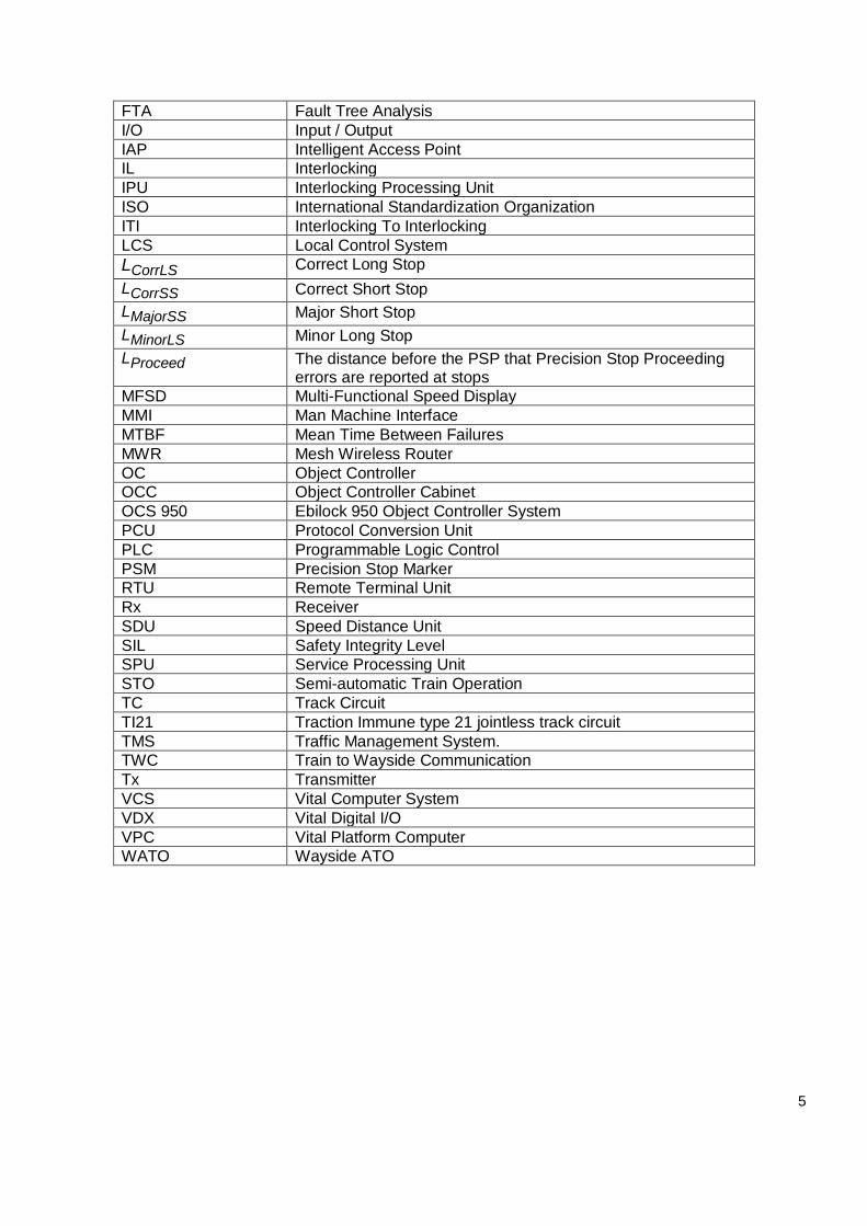
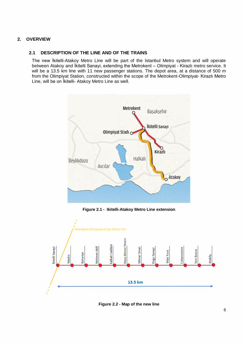
The new İkitelli-Atakoy Metro Line will be part of the Istanbul Metro system and will operate between Atakoy and İkitelli Sanayi, extending the Metrokent – Olimpiyat - Kirazlı metro service. It will be a 13.5 km line with 11 new passenger stations. The depot area, at a distance of 500 m from the Olimpiyat Station, constructed within the scope of the Metrokent-Olimpiyat- Kirazlı Metro Line, will be on İkitelli- Atakoy Metro Line as well.
Figure 2.1 - Ikitelli-Atakoy Metro Line extension
Figure 2.2 - Map of the new line
7
All the data concerning the vehicles are just for completeness, because trains are part of another contract (Alstom). For any inconsistence or error, the reference are only documents provided by Alstom.
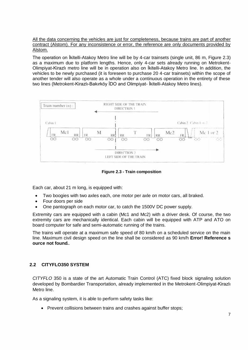
The operation on İkitelli-Atakoy Metro line will be by 4-car trainsets (single unit, 86 m, Figure 2.3) as a maximum due to platform lengths. Hence, only 4-car sets already running on Metrokent-Olimpiyat-Kirazlı metro line will be in operation also on İkitelli-Atakoy Metro line. In addition, the vehicles to be newly purchased (it is foreseen to purchase 20 4-car trainsets) within the scope of another tender will also operate as a whole under a continuous operation in the entirety of these two lines (Metrokent-Kirazlı-Bakırköy İDO and Olimpiyat- İkitelli-Atakoy Metro lines).
Figure 2.3 - Train composition
Each car, about 21 m long, is equipped with:
Two boogies with two axles each, one motor per axle on motor cars, all braked.
Four doors per side
One pantograph on each motor car, to catch the 1500V DC power supply.
Extremity cars are equipped with a cabin (Mc1 and Mc2) with a driver desk. Of course, the two extremity cars are mechanically identical. Each cabin will be equipped with ATP and ATO on board computer for safe and semi-automatic running of the trains.
The trains will operate at a maximum safe speed of 80 km/h on a scheduled service on the main line. Maximum civil design speed on the line shall be considered as 90 km/h Error! Reference source not found..
2.2 CITYFLO350 SYSTEM
CITYFLO 350 is a state of the art Automatic Train Control (ATC) fixed block signaling solution
developed by Bombardier Transportation, already implemented in the Metrokent-Olimpiyat-Kirazlı
Metro line.
As a signaling system, it is able to perform safety tasks like:
Prevent collisions between trains and crashes against buffer stops;
8
Maintain a safe distance between following trains on the same line;
Safeguard the movement of trains through points;
Prevent trains from running too fast;
Control train doors enabling.
Moreover, this system can optimize non-safety-related operations, allowing semiautomatic driving
of the trains (Grade of Automation, GoA, level 2):
Three driving strategies can be chosen in order to minimize travel time, energy
consumption or to have a compromise between them;
A speed profile computed according to the strategy and to the ceiling speed in order to
control acceleration, cruising and precision braking;
A theoretical achievable headway of 90 s in the normal direction and 120 s in the opposite
direction.
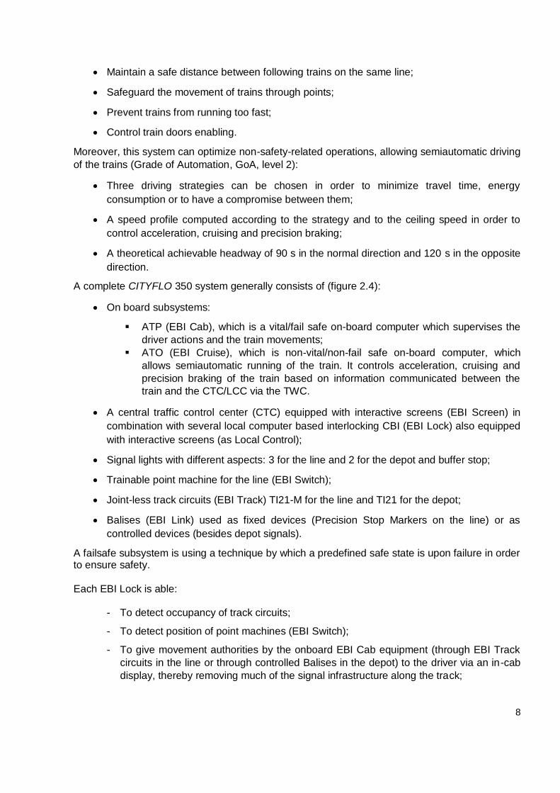
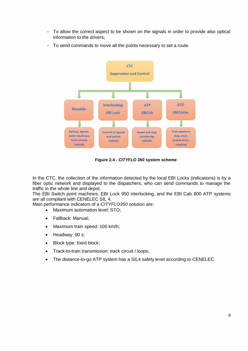
A complete CITYFLO 350 system generally consists of (figure 2.4):
On board subsystems:
ATP (EBI Cab), which is a vital/fail safe on-board computer which supervises the
driver actions and the train movements;
ATO (EBI Cruise), which is non-vital/non-fail safe on-board computer, which
allows semiautomatic running of the train. It controls acceleration, cruising and
precision braking of the train based on information communicated between the
train and the CTC/LCC via the TWC.
A central traffic control center (CTC) equipped with interactive screens (EBI Screen) in
combination with several local computer based interlocking CBI (EBI Lock) also equipped
with interactive screens (as Local Control);
Signal lights with different aspects: 3 for the line and 2 for the depot and buffer stop;
Trainable point machine for the line (EBI Switch);
Joint-less track circuits (EBI Track) TI21-M for the line and TI21 for the depot;
Balises (EBI Link) used as fixed devices (Precision Stop Markers on the line) or as
controlled devices (besides depot signals).
A failsafe subsystem is using a technique by which a predefined safe state is upon failure in order to ensure safety. Each EBI Lock is able:
- To detect occupancy of track circuits;
- To detect position of point machines (EBI Switch);
- To give movement authorities by the onboard EBI Cab equipment (through EBI Track
circuits in the line or through controlled Balises in the depot) to the driver via an in-cab
display, thereby removing much of the signal infrastructure along the track;
9
- To allow the correct aspect to be shown on the signals in order to provide also optical
information to the drivers;
- To send commands to move all the points necessary to set a route.
Figure 2.4 - CITYFLO 350 system scheme
In the CTC, the collection of the information detected by the local EBI Locks (indications) is by a fiber optic network and displayed to the dispatchers, who can send commands to manage the traffic in the whole line and depot. The EBI Switch point machines, EBI Lock 950 interlocking, and the EBI Cab 800 ATP systems are all compliant with CENELEC SIL 4. Main performance indicators of a CITYFLO350 solution are:
Maximum automation level: STO;
Fallback: Manual;
Maximum train speed: 100 km/h;
Headway: 90 s;
Block type: fixed block;
Track-to-train transmission: track circuit / loops;
The distance-to-go ATP system has a SIL4 safety level according to CENELEC.
10
3. SYSTEM ARCHITECTURE
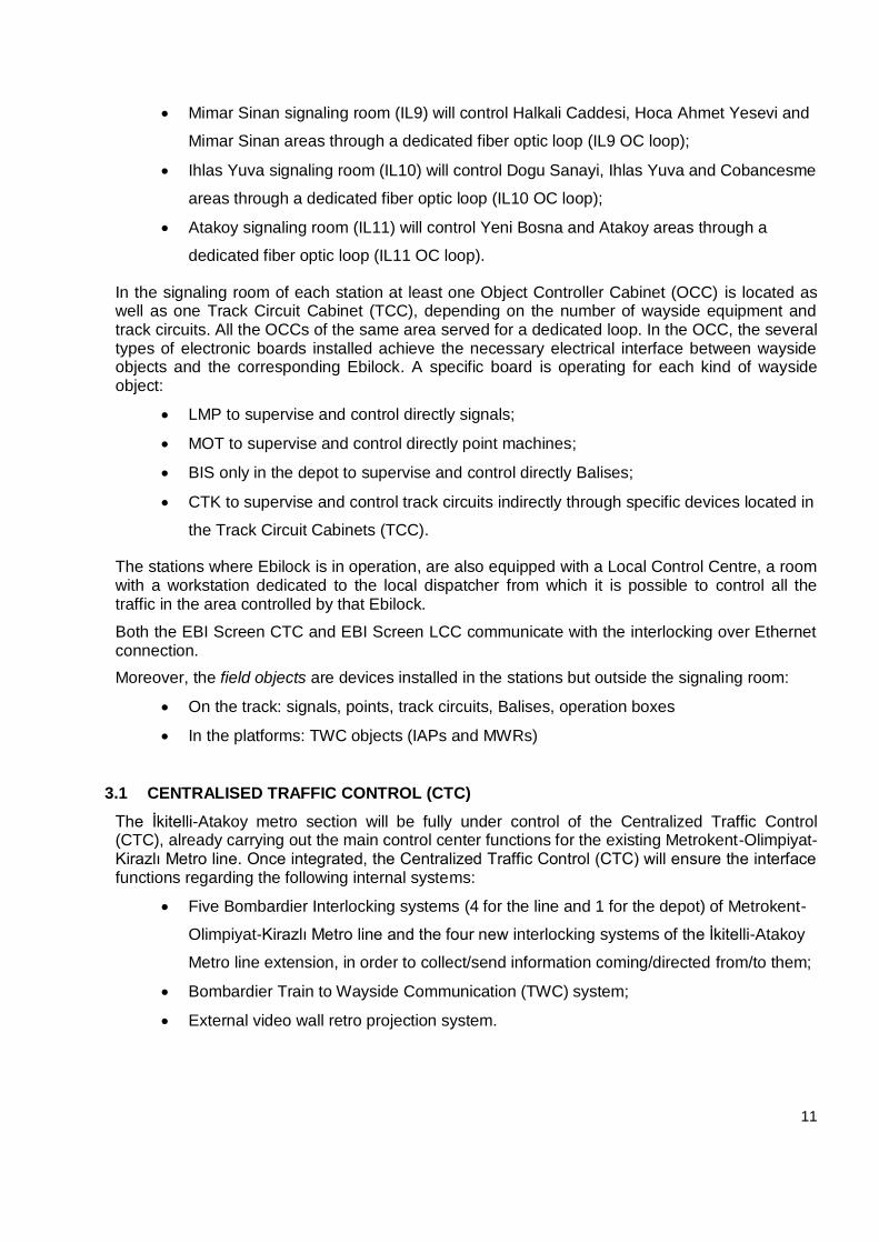
An overview of the CITYFLO 350 system architecture for this specific application is in Figure 3.1.
The İkitelli-Atakoy Metro line architecture will be fully integrated with the existing Metrokent-Olimpiyat-Kirazlı metro line and the operation will be managed by the Central Traffic Control (CTC), whose servers are located in Metrokent (Basak Konut 4) arranged in an equipment room with the following devices:
UPS station;
Two EBIScreen application servers;
EBIScreen maintenance workstation;
TWC servers.
Instead, the CTC clients are located in a control room in Olimpiyat Depot Area, configured in the following way:
Three traffic operator workstations;
One Timetable workstation;
Three 70’’ retro projection modules installed on the wall to provide to the operators a
large line overview video wall.
However, according to the contract, the Control room will move to the Olimpiyat station during the integration the İkitelli-Atakoy Metro line. At this regard, a new floor in Olimpiyat building will construct in order to arrange the equipment.
A redundant Ethernet LAN is under implementation in the whole CTC, so that each server/workstation is in a double backbone link to grant high system availability.
The four Ebilock controlling the new line will communicate with the CTC through the same fiber optic network (CTC/ITI double backbone) already connecting the five Ebilock of the existing line.
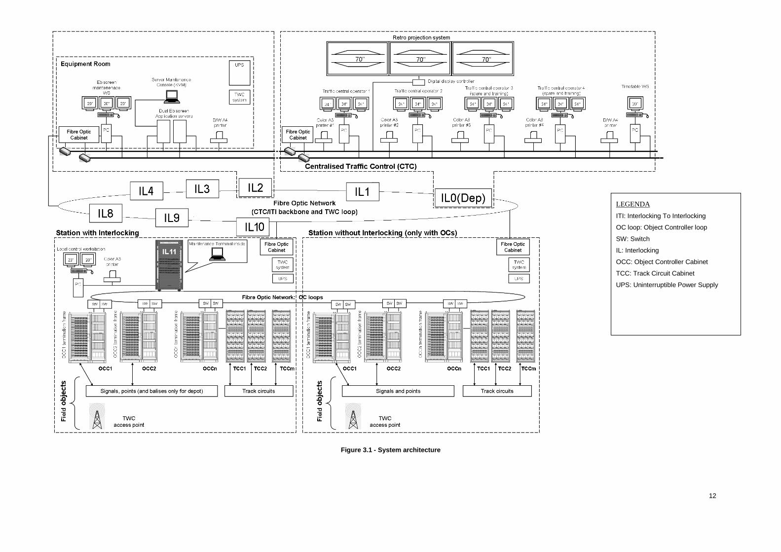
From a signaling point of view, four new interlocking areas will add to the five already in operation (Figure 3.2), the Ebilock located in:
Depot signaling room (IL0) controls just the Depot area through a dedicated fiber optic
loop (IL0 OC loop);
Olimpiyat signaling room (IL1) controls Olimpiyat and Ziya Gökalp areas through a
dedicated fiber optic loop (IL1 OC loop);
Metrokent signaling room (IL2) controls Metrokent, Basak Konutları and Siteler areas
through a dedicated fiber optic loop (IL2 OC loop);
İkitelli Sanayi signaling room (IL3) controls Turgut Özal, İkitelli Sanayi and İstoç areas
through a dedicated fiber optic loop (IL3 OC loop).
Kirazlı signaling room (IL4) controls Mahmutbey, Yenimahalle and Kirazlı areas
through a dedicated fiber optic loop (IL4 OC loop);
Bahariye signaling room (IL8) will control Masko, Bahariye and Mehmet Akif areas
through a dedicated fiber optic loop (IL8 OC loop);
11
Mimar Sinan signaling room (IL9) will control Halkali Caddesi, Hoca Ahmet Yesevi and
Mimar Sinan areas through a dedicated fiber optic loop (IL9 OC loop);
Ihlas Yuva signaling room (IL10) will control Dogu Sanayi, Ihlas Yuva and Cobancesme
areas through a dedicated fiber optic loop (IL10 OC loop);
Atakoy signaling room (IL11) will control Yeni Bosna and Atakoy areas through a
dedicated fiber optic loop (IL11 OC loop).
In the signaling room of each station at least one Object Controller Cabinet (OCC) is located as well as one Track Circuit Cabinet (TCC), depending on the number of wayside equipment and track circuits. All the OCCs of the same area served for a dedicated loop. In the OCC, the several types of electronic boards installed achieve the necessary electrical interface between wayside objects and the corresponding Ebilock. A specific board is operating for each kind of wayside object:
LMP to supervise and control directly signals;
MOT to supervise and control directly point machines;
BIS only in the depot to supervise and control directly Balises;
CTK to supervise and control track circuits indirectly through specific devices located in
the Track Circuit Cabinets (TCC).
The stations where Ebilock is in operation, are also equipped with a Local Control Centre, a room with a workstation dedicated to the local dispatcher from which it is possible to control all the traffic in the area controlled by that Ebilock.
Both the EBI Screen CTC and EBI Screen LCC communicate with the interlocking over Ethernet connection.
Moreover, the field objects are devices installed in the stations but outside the signaling room:
On the track: signals, points, track circuits, Balises, operation boxes
In the platforms: TWC objects (IAPs and MWRs)
3.1 CENTRALISED TRAFFIC CONTROL (CTC)
The İkitelli-Atakoy metro section will be fully under control of the Centralized Traffic Control (CTC), already carrying out the main control center functions for the existing Metrokent-Olimpiyat-Kirazlı Metro line. Once integrated, the Centralized Traffic Control (CTC) will ensure the interface functions regarding the following internal systems:
Five Bombardier Interlocking systems (4 for the line and 1 for the depot) of Metrokent-
Olimpiyat-Kirazlı Metro line and the four new interlocking systems of the İkitelli-Atakoy
Metro line extension, in order to collect/send information coming/directed from/to them;
Bombardier Train to Wayside Communication (TWC) system;
External video wall retro projection system.
12
Figure 3.1 - System architecture
LEGENDA
ITI: Interlocking To Interlocking
OC loop: Object Controller loop
SW: Switch
IL: Interlocking
OCC: Object Controller Cabinet
TCC: Track Circuit Cabinet
UPS: Uninterruptible Power Supply
13
Figure 3.2 - Interlocking areas and network
14
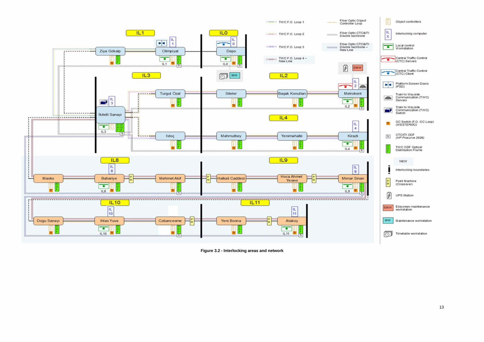
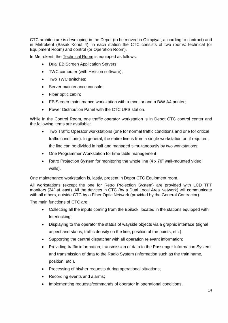
CTC architecture is developing in the Depot (to be moved in Olimpiyat, according to contract) and in Metrokent (Basak Konut 4): in each station the CTC consists of two rooms: technical (or Equipment Room) and control (or Operation Room).
In Metrokent, the Technical Room is equipped as follows:
Dual EBIScreen Application Servers;
TWC computer (with HVision software);
Two TWC switches;
Server maintenance console;
Fiber optic cabin;
EBIScreen maintenance workstation with a monitor and a B/W A4 printer;
Power Distribution Panel with the CTC UPS station.
While in the Control Room, one traffic operator workstation is in Depot CTC control center and the following items are available:
Two Traffic Operator workstations (one for normal traffic conditions and one for critical
traffic conditions). In general, the entire line is from a single workstation or, if required,
the line can be divided in half and managed simultaneously by two workstations;
One Programmer Workstation for time table management;
Retro Projection System for monitoring the whole line (4 x 70” wall-mounted video
walls).
One maintenance workstation is, lastly, present in Depot CTC Equipment room.
All workstations (except the one for Retro Projection System) are provided with LCD TFT monitors (24” at least). All the devices in CTC (by a Dual Local Area Network) will communicate with all others, outside CTC by a Fiber Optic Network (provided by the General Contractor).
The main functions of CTC are:
Collecting all the inputs coming from the Ebilock, located in the stations equipped with
Interlocking;
Displaying to the operator the status of wayside objects via a graphic interface (signal
aspect and status, traffic density on the line, position of the points, etc.);
Supporting the central dispatcher with all operation relevant information;
Providing traffic information, transmission of data to the Passenger Information System
and transmission of data to the Radio System (information such as the train name,
position, etc.),
Processing of his/her requests during operational situations;
Recording events and alarms;
Implementing requests/commands of operator in operational conditions.
15
From a software point of view, it is including several subsystems:
Core of the EBIScreen system dedicated to the processing of indications (coming from
the field) and commands sent by the operator (typically setting and canceling of
routes);
Authority Management System which acts as a filter, showing to an operator only the
information he/she is allowed to see and the commands he/she is allowed to send;
Event Logging and Alarms module: conceived to keep track of any kind of events and
especially alarms;
Train Describer (TD), whose purpose is to identify trains within the system area and
maintain train position information of these trains according to the detection information
provided by track circuits;
Timetable Management System which allows the operator to plan the seasonal
timetable with all the exceptions (holydays, Sundays, etc.) plus the possibility for the
operator to modify it online following the changing of the actual traffic;
Automating routing and automatons conceived to relieve the operators from their
routine routing tasks;
Data Archiving: it allows the storing of the events into CSV files in a system hard disk
for e.g. 6 months.
3.2 ENVIROMENTAL CONDITION
The İkitelli-Atakoy Metro Line signaling system will be under design and manufacture according the following requirements:
Compliancy with EN 50126, EN 50128 and EN 50129 standards;
Hardware, software and transmission network are fail-safe (SIL-4 level) in order to
guarantee operation under the following conditions;
Ambient temperature on line: min -10°C, Max +50°C;
Ambient temperature in tunnel: min +2°C, Max +34°C;
Ambient temperature in the CTC: between +18°C and +25°C;
Relative humidity of the air: between 5% and 95% at 20°C;
Degree of pollution: neutral atmosphere.
Moreover, all the equipment installed in open areas or subject to external ambient conditions will be IP66.
16
3.3 COMMUNICATION SYSTEM
The İkitelli-Ataköy metro line operations and functions will be under management by an appropriate communication system, which will integrate the Metrokent-Olimpiyat-Kirazlı Metro line. At last, it will consist of:
A double backbone for CTC and ITI function;
A set of nine OC loops;
At least, four loops (exactly four closed backbones) for TWC function. Three of them
are already working for the existing line.
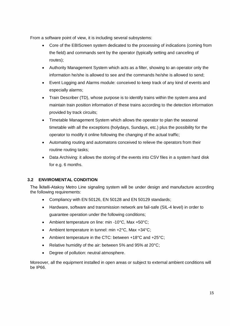
The CTC and ITI network is physically a double backbone (two pairs of optical fibers) which performs two different functions:
Connecting CTC with all the Interlocking equipped stations, in order to collect and
centralize the information coming from the nine areas managed by the Ebilock (CTC
function);
Allowing each Ebilock to exchange information with the adjacent ones (ITI function).
The Figure 3.3 shows the locations logically connected by the CTC and ITI network.
Figure 3.3 - CTC and ITI double backbone scheme
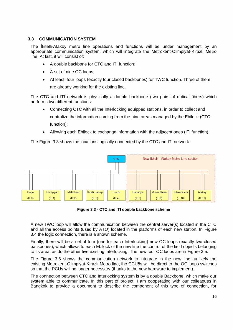
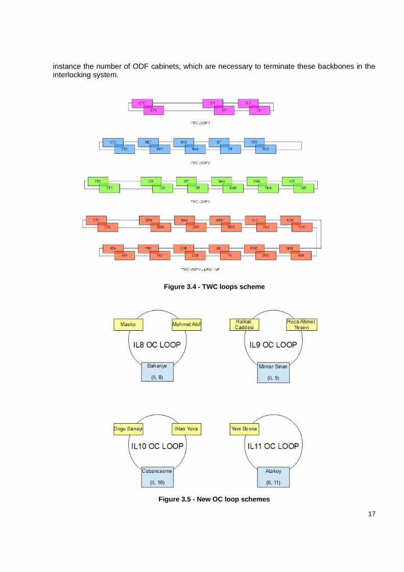
A new TWC loop will allow the communication between the central server(s) located in the CTC and all the access points (used by ATO) located in the platforms of each new station. In Figure 3.4 the logic connection, there is a shown scheme.
Finally, there will be a set of four (one for each Interlocking) new OC loops (exactly two closed backbones), which allows to each Ebilock of the new line the control of the field objects belonging to its area, as do the other five existing Interlocking. The new four OC loops are in Figure 3.5.
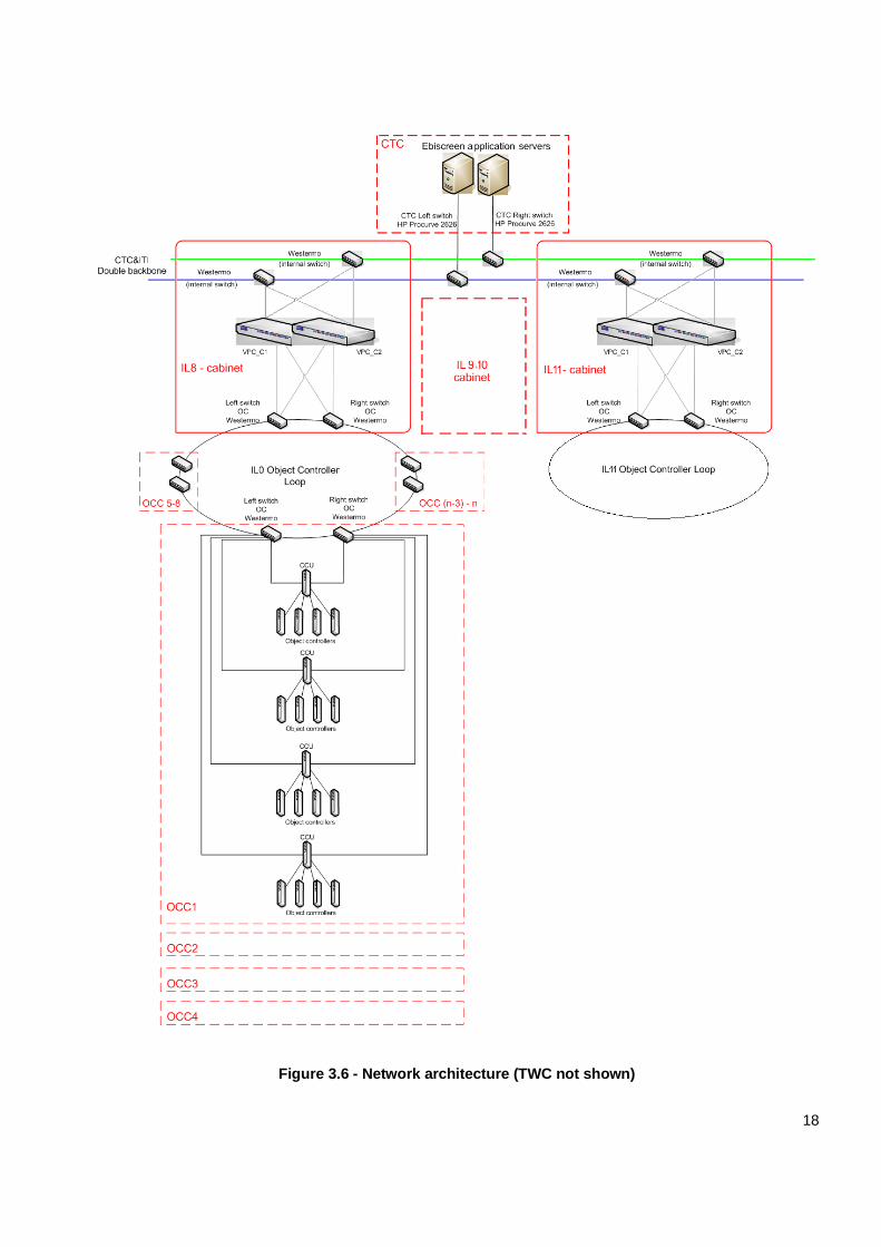
The Figure 3.6 shows the communication network to integrate in the new line: unlikely the existing Metrokent-Olimpiyat-Kirazlı Metro line, the CCU5s will be direct to the OC loops switches so that the PCUs will no longer necessary (thanks to the new hardware to implement).
The connection between CTC and Interlocking system is by a double Backbone, which make our system able to communicate. In this part of project, I am cooperating with our colleagues in Bangkok to provide a document to describe the component of this type of connection, for
17
instance the number of ODF cabinets, which are necessary to terminate these backbones in the interlocking system.
Figure 3.4 - TWC loops scheme
Figure 3.5 - New OC loop schemes
18
Figure 3.6 - Network architecture (TWC not shown)
19
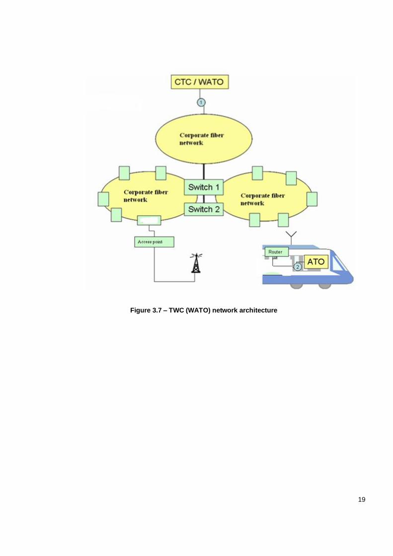
Figure 3.7 – TWC (WATO) network architecture
20
3.4 COMPUTER BASED INTERLOCKING (EBILOCK 950)
Ebilock is a computer based electronic interlocking system. It has been designed for all types of rail traffic, with stations of several sizes and providing the availability required by the Infrastructure Managers. The modular hardware and software operates reliably with minimum maintenance needs. Ebilock includes a fully redundant interlocking computer and duplicated transmission and communication units.
Ebilock has been designed to fulfill the highest safety standards in the signaling industry. It satisfies the requirements for Safety Integrity Level 4 (SIL4) in the CENELEC standards. Diversified software is one important means to reach this high safety level.
Interlocking system includes the IPU cabinets and the bridge between CTC and OC system, which is getting under control by maintenance computer.
This part of the project was dedicated to install the software which is operating this terminal.
The software has been provided by Bombardier Transportation Bangkok and we were required to follow those steps guiding to install it.
The scope of this software is making the user able to control the operations of VPCs and activate manual commands whenever necessary. Keeping the stand by VPC update, it keeps the ability to enter into operation under request.
In addition, each IPU cabinet will be in charge for maximum 3 stations. Therefore, the project involves 4 cabinets covering 11 stations.
Ebilock features (figure 3.8):
Vital platform concept with dual channel diversity on the hardware, operating system
and application levels for vital functions;
Use of commercial-off-the-shelf (COTS) hardware and operating systems with a
standardized application programming interface;
Internal and external communication using COTS Ethernet switches and TCP/IP
protocol.
The computer-based interlocking mainly:
Receives commands from railway traffic control center (local or centralized) and
evaluates them with respect to traffic safety rules and the actual traffic situation. Only
safe commands can be executed;
Monitors the railway infrastructure and the state of the traffic continuously and sends
information regarding them back to the control center (local and centralized).
The structure of Ebilock includes three major parts:
Vital Computer System (VCS) (details in §3.4.1);
Transmission system (details in §3.4.2);
Object Controller System (OCS) (details in §3.4.3).

21
Figure 3.8 - Ebilock scheme
The VCS performs the interlocking function, receiving and evaluating commands from the control center, sending orders to the object controller, receiving status information from the object controller system and sending status indications back to the LCC and to the CTC.
The transmission system is the closed network for communication between the CIS and the OCS, not indicated in Figure 3.6 because internal to each Ebilock. It is made of switches and, in the existing line, of PCUs.
The OCS controls the wayside objects, such as signals, point machines, depot Balises, track circuits, receiving and executing orders from the central interlocking system through the transmission system, monitoring object status and sending status information back to the central interlocking system through the transmission system.
As shown in the Figure 3.8, the Local Control Center (LCC) (Control Centre in the figure) is not
part of the computer-based interlocking but it is a necessary component of the system, which provides locally a Man-Machine Interface to the operator for traffic, internal and external systems management. Only a subset of the functions available in the CTC will be available from the Local control workstation and the functions available will be geographically limited to the area controlled by that interlocking.
3.4.1 VITAL COMPUTER SYSTEM (VCS)
The core of the Interlocking functions is the Vital Platform Unit (VPU). It is made of three main components: two Vital Computer System (VCS) configured in a redundant (online-stand by) configuration in order to increase availability and one local maintenance terminal. There are two version of VCS: normal (VCS_N) for standard environment condition but with high performance and rugged (VCS_R) for harder conditions but lower performance. For the İkitelli-Ataköy only normal VCS will be used.
The two identical computing subsystems are employed so that the online VCS keeps the standby
VCS updated, and the standby VCS can take over immediately and automatically in case the online fails. In case of failure, the operator has just to acknowledge the alarm generates by the system.
22
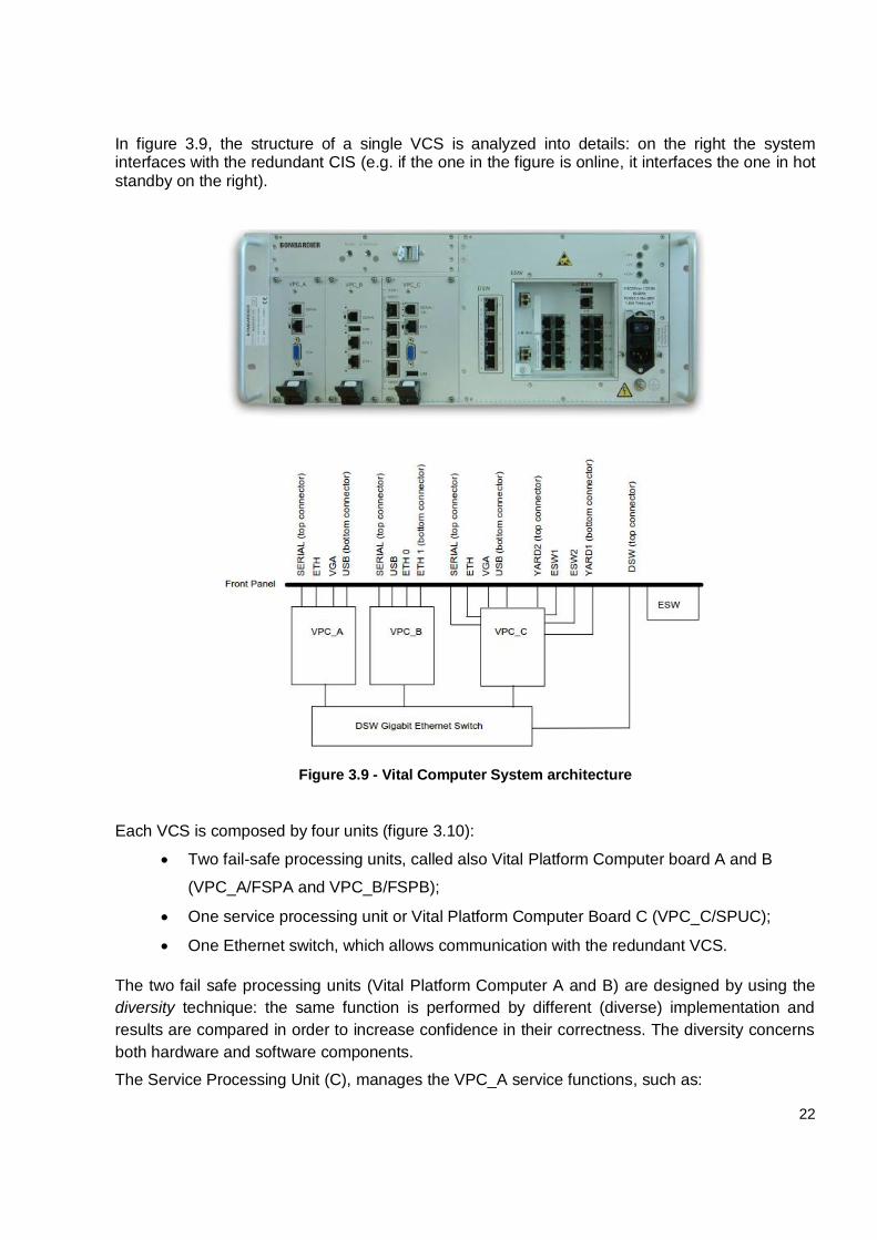
In figure 3.9, the structure of a single VCS is analyzed into details: on the right the system interfaces with the redundant CIS (e.g. if the one in the figure is online, it interfaces the one in hot standby on the right).
Figure 3.9 - Vital Computer System architecture
Each VCS is composed by four units (figure 3.10):
Two fail-safe processing units, called also Vital Platform Computer board A and B
(VPC_A/FSPA and VPC_B/FSPB);
One service processing unit or Vital Platform Computer Board C (VPC_C/SPUC);
One Ethernet switch, which allows communication with the redundant VCS.
The two fail safe processing units (Vital Platform Computer A and B) are designed by using the
diversity technique: the same function is performed by different (diverse) implementation and
results are compared in order to increase confidence in their correctness. The diversity concerns
both hardware and software components.
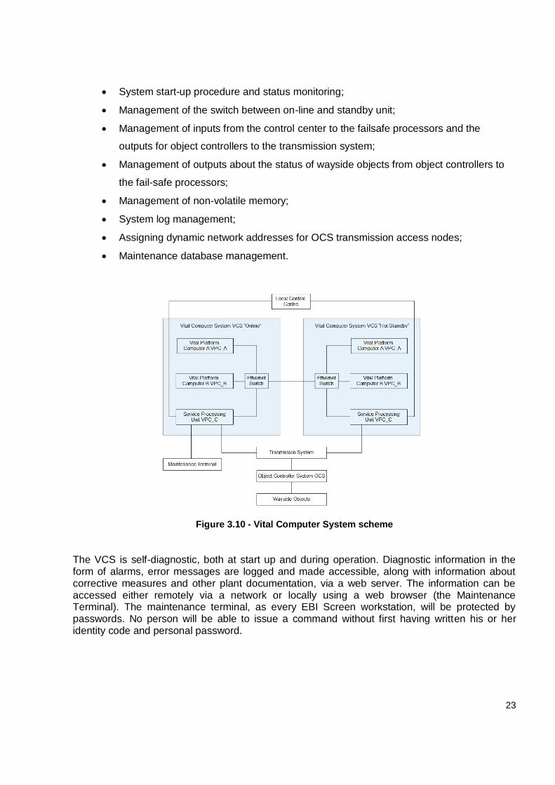
The Service Processing Unit (C), manages the VPC_A service functions, such as:
23
System start-up procedure and status monitoring;
Management of the switch between on-line and standby unit;
Management of inputs from the control center to the failsafe processors and the
outputs for object controllers to the transmission system;
Management of outputs about the status of wayside objects from object controllers to
the fail-safe processors;
Management of non-volatile memory;
System log management;
Assigning dynamic network addresses for OCS transmission access nodes;
Maintenance database management.
Figure 3.10 - Vital Computer System scheme
The VCS is self-diagnostic, both at start up and during operation. Diagnostic information in the form of alarms, error messages are logged and made accessible, along with information about corrective measures and other plant documentation, via a web server. The information can be accessed either remotely via a network or locally using a web browser (the Maintenance Terminal). The maintenance terminal, as every EBI Screen workstation, will be protected by passwords. No person will be able to issue a command without first having written his or her identity code and personal password.
24
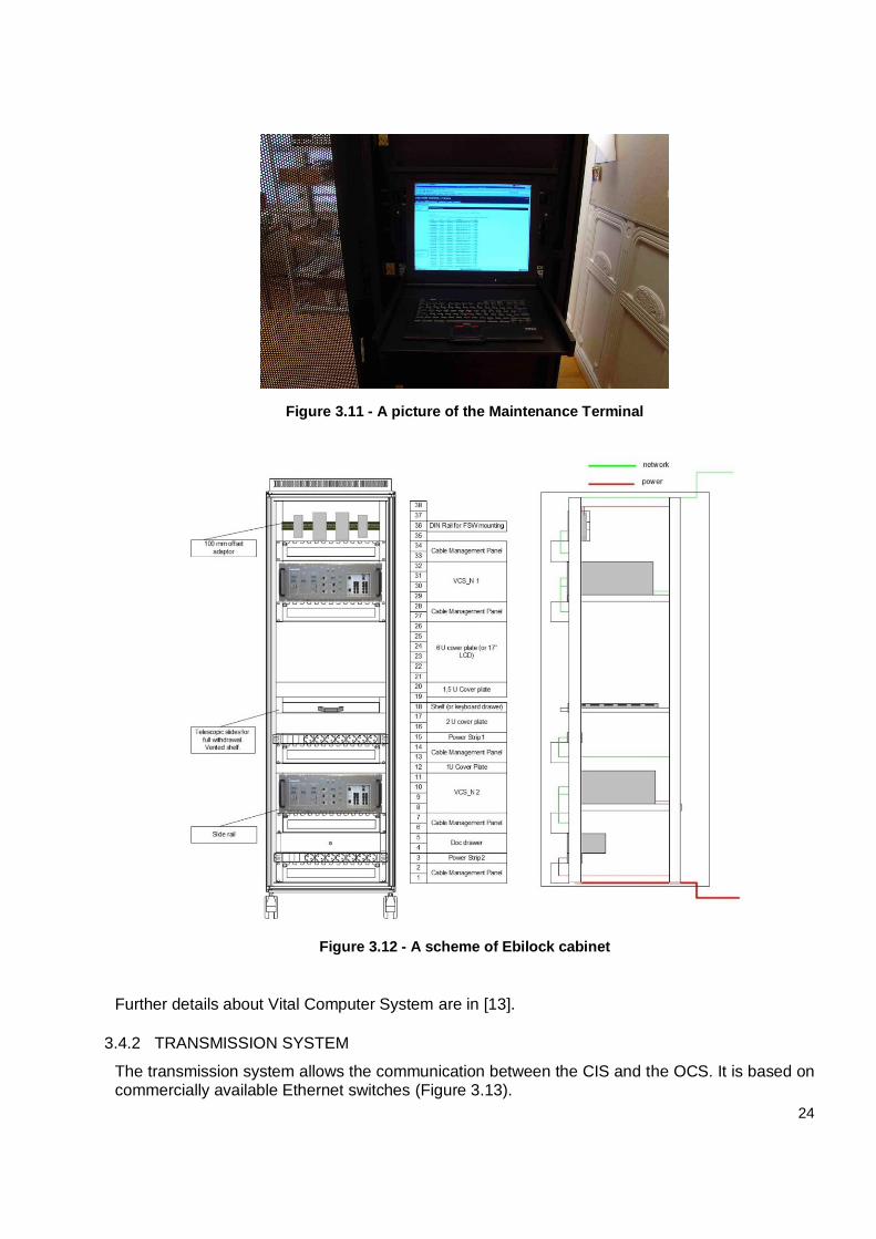
Figure 3.11 - A picture of the Maintenance Terminal
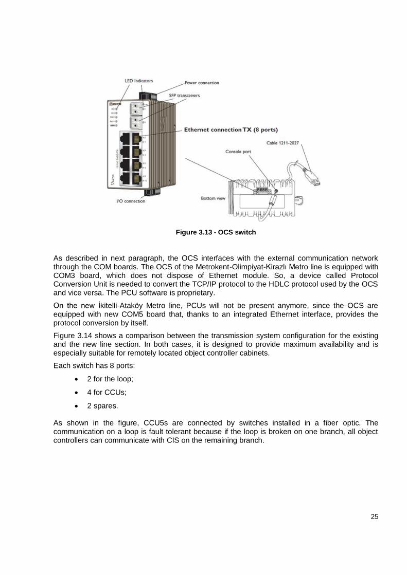
Figure 3.12 - A scheme of Ebilock cabinet
Further details about Vital Computer System are in [13].
3.4.2 TRANSMISSION SYSTEM
The transmission system allows the communication between the CIS and the OCS. It is based on commercially available Ethernet switches (Figure 3.13).
25
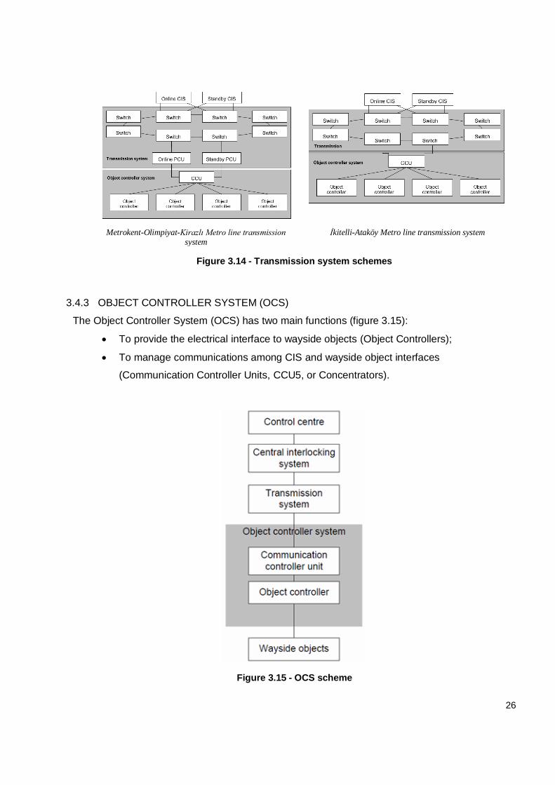
Figure 3.13 - OCS switch
As described in next paragraph, the OCS interfaces with the external communication network through the COM boards. The OCS of the Metrokent-Olimpiyat-Kirazlı Metro line is equipped with COM3 board, which does not dispose of Ethernet module. So, a device called Protocol Conversion Unit is needed to convert the TCP/IP protocol to the HDLC protocol used by the OCS and vice versa. The PCU software is proprietary.
On the new İkitelli-Ataköy Metro line, PCUs will not be present anymore, since the OCS are equipped with new COM5 board that, thanks to an integrated Ethernet interface, provides the protocol conversion by itself.
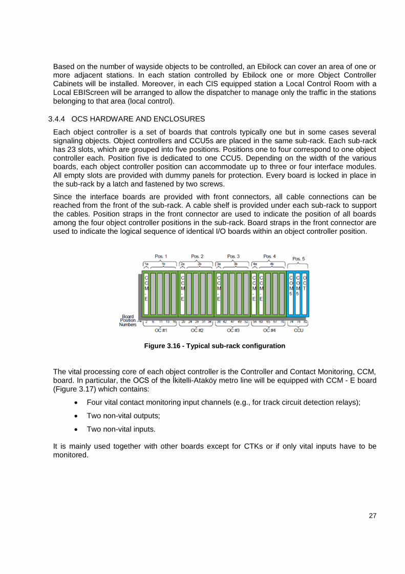
Figure 3.14 shows a comparison between the transmission system configuration for the existing and the new line section. In both cases, it is designed to provide maximum availability and is especially suitable for remotely located object controller cabinets.
Each switch has 8 ports:
2 for the loop;
4 for CCUs;
2 spares.
As shown in the figure, CCU5s are connected by switches installed in a fiber optic. The communication on a loop is fault tolerant because if the loop is broken on one branch, all object controllers can communicate with CIS on the remaining branch.
26
Metrokent-Olimpiyat-Kirazlı Metro line transmission system
İkitelli-Ataköy Metro line transmission system
Figure 3.14 - Transmission system schemes
3.4.3 OBJECT CONTROLLER SYSTEM (OCS)
The Object Controller System (OCS) has two main functions (figure 3.15):
To provide the electrical interface to wayside objects (Object Controllers);
To manage communications among CIS and wayside object interfaces
(Communication Controller Units, CCU5, or Concentrators).
Figure 3.15 - OCS scheme
27
Based on the number of wayside objects to be controlled, an Ebilock can cover an area of one or more adjacent stations. In each station controlled by Ebilock one or more Object Controller Cabinets will be installed. Moreover, in each CIS equipped station a Local Control Room with a Local EBIScreen will be arranged to allow the dispatcher to manage only the traffic in the stations belonging to that area (local control).
3.4.4 OCS HARDWARE AND ENCLOSURES
Each object controller is a set of boards that controls typically one but in some cases several signaling objects. Object controllers and CCU5s are placed in the same sub-rack. Each sub-rack has 23 slots, which are grouped into five positions. Positions one to four correspond to one object controller each. Position five is dedicated to one CCU5. Depending on the width of the various boards, each object controller position can accommodate up to three or four interface modules. All empty slots are provided with dummy panels for protection. Every board is locked in place in the sub-rack by a latch and fastened by two screws.
Since the interface boards are provided with front connectors, all cable connections can be reached from the front of the sub-rack. A cable shelf is provided under each sub-rack to support the cables. Position straps in the front connector are used to indicate the position of all boards among the four object controller positions in the sub-rack. Board straps in the front connector are used to indicate the logical sequence of identical I/O boards within an object controller position.
Figure 3.16 - Typical sub-rack configuration
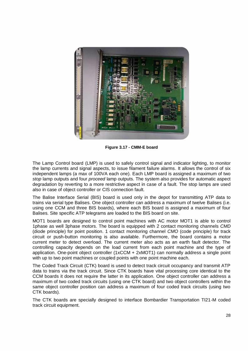
The vital processing core of each object controller is the Controller and Contact Monitoring, CCM, board. In particular, the OCS of the İkitelli-Ataköy metro line will be equipped with CCM - E board (Figure 3.17) which contains:
Four vital contact monitoring input channels (e.g., for track circuit detection relays);
Two non-vital outputs;
Two non-vital inputs.
It is mainly used together with other boards except for CTKs or if only vital inputs have to be monitored.
28
Figure 3.17 - CMM-E board
The Lamp Control board (LMP) is used to safely control signal and indicator lighting, to monitor the lamp currents and signal aspects, to issue filament failure alarms. It allows the control of six independent lamps (a max of 100VA each one). Each LMP board is assigned a maximum of two stop lamp outputs and four proceed lamp outputs. The system also provides for automatic aspect
degradation by reverting to a more restrictive aspect in case of a fault. The stop lamps are used also in case of object controller or CIS connection fault.
The Balise Interface Serial (BIS) board is used only in the depot for transmitting ATP data to trains via serial type Balises. One object controller can address a maximum of twelve Balises (i.e. using one CCM and three BIS boards), where each BIS board is assigned a maximum of four Balises. Site specific ATP telegrams are loaded to the BIS board on site.
MOT1 boards are designed to control point machines with AC motor MOT1 is able to control 1phase as well 3phase motors. The board is equipped with 2 contact monitoring channels CMD (diode principle) for point position. 1 contact monitoring channel CMO (code principle) for track
circuit or push-button monitoring is also available. Furthermore, the board contains a motor current meter to detect overload. The current meter also acts as an earth fault detector. The controlling capacity depends on the load current from each point machine and the type of application. One-point object controller (1xCCM + 2xMOT1) can normally address a single point with up to two point machines or coupled points with one point machine each.
The Coded Track Circuit (CTK) board is used to detect track circuit occupancy and transmit ATP data to trains via the track circuit. Since CTK boards have vital processing core identical to the CCM boards it does not require the latter in its application. One object controller can address a maximum of two coded track circuits (using one CTK board) and two object controllers within the same object controller position can address a maximum of four coded track circuits (using two CTK boards).
The CTK boards are specially designed to interface Bombardier Transportation TI21-M coded track circuit equipment.
29
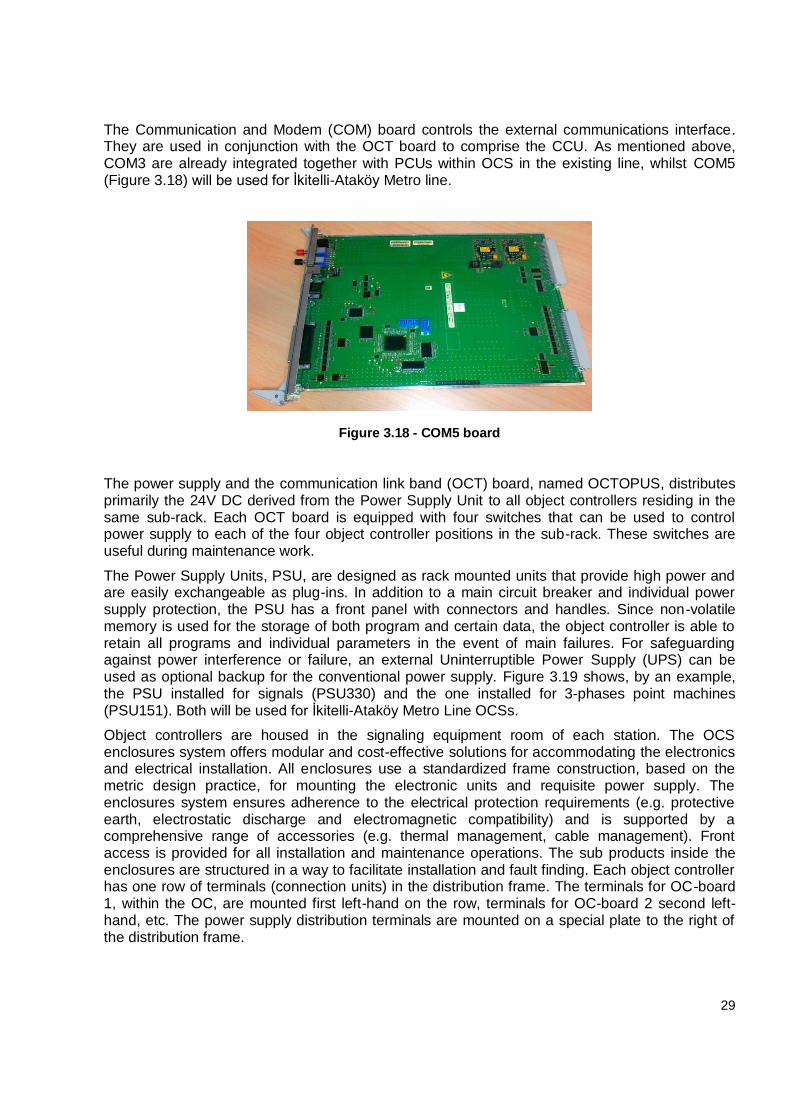
The Communication and Modem (COM) board controls the external communications interface. They are used in conjunction with the OCT board to comprise the CCU. As mentioned above, COM3 are already integrated together with PCUs within OCS in the existing line, whilst COM5 (Figure 3.18) will be used for İkitelli-Ataköy Metro line.
Figure 3.18 - COM5 board
The power supply and the communication link band (OCT) board, named OCTOPUS, distributes primarily the 24V DC derived from the Power Supply Unit to all object controllers residing in the same sub-rack. Each OCT board is equipped with four switches that can be used to control power supply to each of the four object controller positions in the sub-rack. These switches are useful during maintenance work.
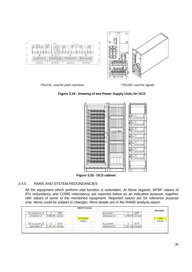
The Power Supply Units, PSU, are designed as rack mounted units that provide high power and are easily exchangeable as plug-ins. In addition to a main circuit breaker and individual power supply protection, the PSU has a front panel with connectors and handles. Since non-volatile memory is used for the storage of both program and certain data, the object controller is able to retain all programs and individual parameters in the event of main failures. For safeguarding against power interference or failure, an external Uninterruptible Power Supply (UPS) can be used as optional backup for the conventional power supply. Figure 3.19 shows, by an example, the PSU installed for signals (PSU330) and the one installed for 3-phases point machines (PSU151). Both will be used for İkitelli-Ataköy Metro Line OCSs.
Object controllers are housed in the signaling equipment room of each station. The OCS enclosures system offers modular and cost-effective solutions for accommodating the electronics and electrical installation. All enclosures use a standardized frame construction, based on the metric design practice, for mounting the electronic units and requisite power supply. The enclosures system ensures adherence to the electrical protection requirements (e.g. protective earth, electrostatic discharge and electromagnetic compatibility) and is supported by a comprehensive range of accessories (e.g. thermal management, cable management). Front access is provided for all installation and maintenance operations. The sub products inside the enclosures are structured in a way to facilitate installation and fault finding. Each object controller has one row of terminals (connection units) in the distribution frame. The terminals for OC-board 1, within the OC, are mounted first left-hand on the row, terminals for OC-board 2 second left-hand, etc. The power supply distribution terminals are mounted on a special plate to the right of the distribution frame.
30
PSU151, used for point machines PSU330, used for signals
Figure 3.19 - Drawing of two Power Supply Units for OCS
Figure 3.20 - OCS cabinet
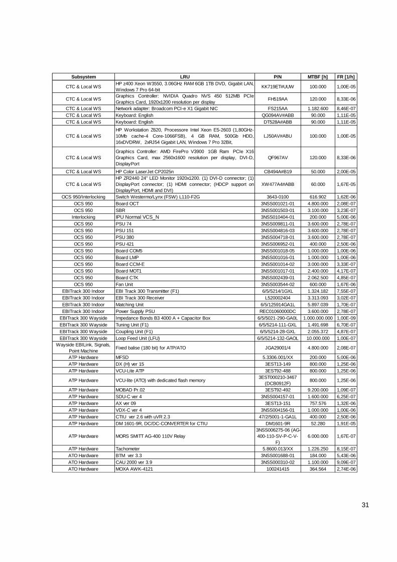
3.4.5 RAMS AND SYSTEM REDUNDANCIES
All the equipment which perform vital function is redundant. At these regards, MTBF values of IPU redundancy and COM5 redundancy are reported below as an indicative purpose, together with values of some of the mentioned equipment. Reported values are for reference purpose only. Items could be subject to changes. More details are in the RAMS analysis report.
31
Subsystem LRU P/N MTBF [h] FR [1/h]
CTC & Local WSHP z400 Xeon W3550, 3.06GHz RAM 6GB 1TB DVD, Gigabit LAN,
Windows 7 Pro 64-bitKK719ET#UUW 100.000 1,00E-05
CTC & Local WSGraphics Controller: NVIDIA Quadro NVS 450 512MB PCIe
Graphics Card, 1920x1200 resolution per displayFH519AA 120.000 8,33E-06
CTC & Local WS Network adapter: Broadcom PCI-e X1 Gigabit NIC FS215AA 1.182.600 8,46E-07
CTC & Local WS Keyboard: English QG094AV#ABB 90.000 1,11E-05
CTC & Local WS Keyboard: English DT528A#ABB 90.000 1,11E-05
CTC & Local WS
HP Workstation Z620, Processore Intel Xeon E5-2603 (1,80GHz-
10Mb cache-4 Core-1066FSB), 4 GB RAM, 500Gb HDD,
16xDVDRW, 2xRJ54 Gigabit LAN, Windows 7 Pro 32Bit,
LJ50AV#ABU 100.000 1,00E-05
CTC & Local WS
Graphics Controller: AMD FirePro V3900 1GB Ram PCIe X16
Graphics Card, max 2560x1600 resolution per display, DVI-D,
DisplayPort
QF967AV 120.000 8,33E-06
CTC & Local WS HP Color LaserJet CP2025n CB494A#B19 50.000 2,00E-05
CTC & Local WS
HP ZR2440 24" LED Monitor 1920x1200. (1) DVI-D connector; (1)
DisplayPort connector; (1) HDMI connector; (HDCP support on
DisplayPort, HDMI and DVI)
XW477A4#ABB 60.000 1,67E-05
OCS 950/Interlocking Switch Westermo/Lynx (FSW) L110-F2G 3643-0100 616.902 1,62E-06
OCS 950 Board OCT 3NSS001021-01 4.800.000 2,08E-07
OCS 950 SBR 3NSS001503-01 3.100.000 3,23E-07
Interlocking IPU Normal VCS_N 3NSS010404-01 200.000 5,00E-06
OCS 950 PSU 74 3NSS009811-01 3.600.000 2,78E-07
OCS 950 PSU 151 3NSS004816-03 3.600.000 2,78E-07
OCS 950 PSU 380 3NSS004718-01 3.600.000 2,78E-07
OCS 950 PSU 421 3NSS006952-01 400.000 2,50E-06
OCS 950 Board COM5 3NSS001018-05 1.000.000 1,00E-06
OCS 950 Board LMP 3NSS001016-01 1.000.000 1,00E-06
OCS 950 Board CCM-E 3NSS001014-02 3.000.000 3,33E-07
OCS 950 Board MOT1 3NSS001017-01 2.400.000 4,17E-07
OCS 950 Board CTK 3NSS002439-01 2.062.500 4,85E-07
OCS 950 Fan Unit 3NSS003544-02 600.000 1,67E-06
EBITrack 300 Indoor EBI Track 300 Transmitter (F1) 6/5/5214/1GXL 1.324.182 7,55E-07
EBITrack 300 Indoor EBI Track 300 Receiver L520002404 3.313.093 3,02E-07
EBITrack 300 Indoor Matching Unit 6/5/125914GA1L 5.897.039 1,70E-07
EBITrack 300 Indoor Power Supply PSU REC01060000DC 3.600.000 2,78E-07
EBITrack 300 Wayside Impedance Bonds B3 4000 A + Capacitor Box 6/5/5021-290-GA0L 1.000.000.000 1,00E-09
EBITrack 300 Wayside Tuning Unit (F1) 6/5/5214-111-GXL 1.491.698 6,70E-07
EBITrack 300 Wayside Coupling Unit (F1) 6/5/5214-28-GXL 2.055.372 4,87E-07
EBITrack 300 Wayside Loop Feed Unit (LFU) 6/5/5214-132-GAOL 10.000.000 1,00E-07
Wayside EBILink, Signals,
Point MachineFixed balise (180 bit) for ATP/ATO JGA29001/4 4.800.000 2,08E-07
ATP Hardware MFSD 5.3306.001/XX 200.000 5,00E-06
ATP Hardware DX (H) ver 15 3EST13-149 800.000 1,25E-06
ATP Hardware VCU-Lite ATP 3EST92-488 800.000 1,25E-06
ATP Hardware VCU-lite (ATO) with dedicated flash memory 3EST000210-3467
(DCB0912F)800.000 1,25E-06
ATP Hardware MOBAD Pr.02 3EST92-492 9.200.000 1,09E-07
ATP Hardware SDU-C ver 4 3NSS004157-01 1.600.000 6,25E-07
ATP Hardware AX ver 09 3EST13-151 757.576 1,32E-06
ATP Hardware VDX-C ver 4 3NSS004156-01 1.000.000 1,00E-06
ATP Hardware CTIU ver 2.6 with uVR 2.3 47/2/5001-1-GA1L 400.000 2,50E-06
ATP Hardware DM 1601-9R, DC/DC-CONVERTER for CTIU DM1601-9R 52.280 1,91E-05
ATP Hardware MORS SMITT AG-400 110V Relay
3NSS006275-06 (AG-
400-110-SV-P-C-V-
F)
6.000.000 1,67E-07
ATP Hardware Tachometer 5.8600.013/XX 1.226.250 8,15E-07
ATO Hardware BTM ver 3.3 3NSS001688-01 184.000 5,43E-06
ATO Hardware CAU 2000 ver 3.9 3NSS000310-02 1.100.000 9,09E-07
ATO Hardware MOXA AWK-4121 100241415 364.564 2,74E-06
32
Moreover, a double communication backbone ensures the highest level of integrity of the network and of the system. Below, MTBF value of switch redundancy.
3.5 WAYSIDE OBJECTS
3.5.1 SIGNALS
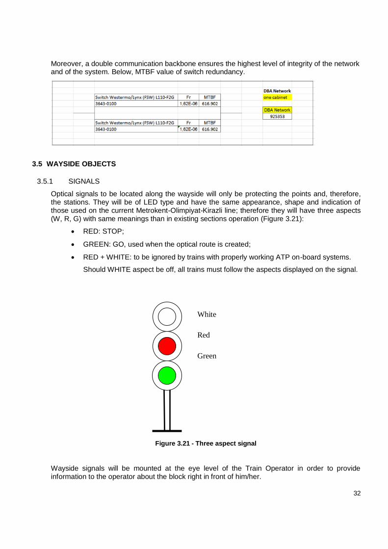
Optical signals to be located along the wayside will only be protecting the points and, therefore, the stations. They will be of LED type and have the same appearance, shape and indication of those used on the current Metrokent-Olimpiyat-Kirazli line; therefore they will have three aspects (W, R, G) with same meanings than in existing sections operation (Figure 3.21):
RED: STOP;
GREEN: GO, used when the optical route is created;
RED + WHITE: to be ignored by trains with properly working ATP on-board systems.
Should WHITE aspect be off, all trains must follow the aspects displayed on the signal.
Figure 3.21 - Three aspect signal
Wayside signals will be mounted at the eye level of the Train Operator in order to provide information to the operator about the block right in front of him/her.
White
Red
Green
33
The adopted signaling system will comply with the general signaling principles for ensuring optimum train operation at all existing traffic modes.
Manufacturing will be ensured taking into consideration the current dynamic envelope of the trains to allow access to all signal lights mounted in the tunnel. Dimensions and electric parameters definition are fine-tuned in this work.
3.5.2 TRACK CIRCUITS
Following the setup of the Metrokent-Olimpiyat-Kirazlı metro line, the track circuit foreseen for this project will be of joint-less type with telegram codes to be sent to the train (TI21-M). However, it will be necessary to use physically (isolated fishplates) at specific points, e.g. for cross-overs.
TI21-M track circuits are used for the whole line and for the depot test track and it allows circulation of the draining currents through both rails. It employs electrical joints which, through a frequency filter system, provide electrical separation without any need of cutting the rails (joint-less). The TI21-M track circuit is an Audio Frequency joint-less one. It employs eight frequencies in the range of 6.1÷8.1 kHz; the nominal frequencies are usually referred to by F1, F2, F3, F4, F5, F6, F7 and F8. The eight nominal frequencies are used as four pairs: F1/F2, F3/F4, F5/F6, and F7/F8. One pair is used per track and they are alternated.
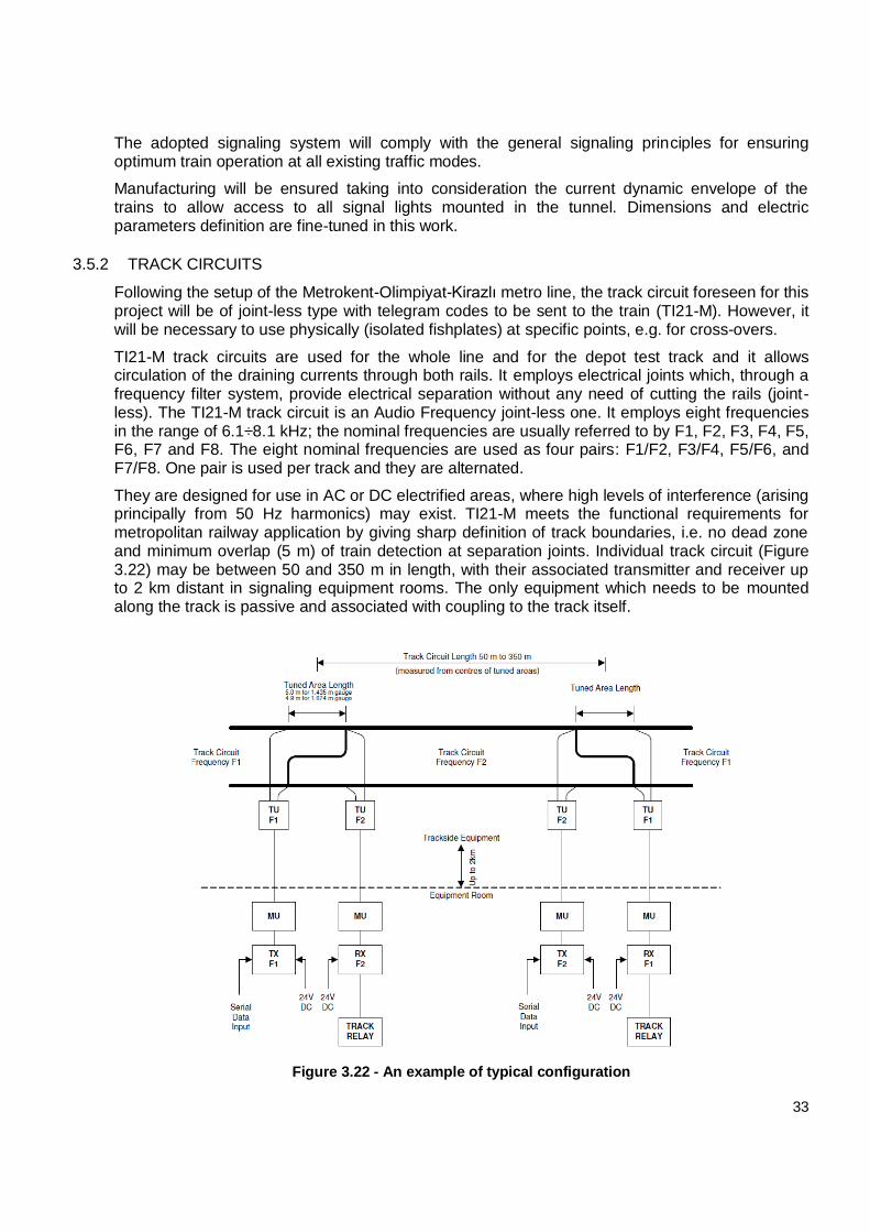
They are designed for use in AC or DC electrified areas, where high levels of interference (arising principally from 50 Hz harmonics) may exist. TI21-M meets the functional requirements for metropolitan railway application by giving sharp definition of track boundaries, i.e. no dead zone and minimum overlap (5 m) of train detection at separation joints. Individual track circuit (Figure 3.22) may be between 50 and 350 m in length, with their associated transmitter and receiver up to 2 km distant in signaling equipment rooms. The only equipment which needs to be mounted along the track is passive and associated with coupling to the track itself.
Figure 3.22 - An example of typical configuration
34
As well as providing safe train detection, TI21-M can also be used to transmit data (speed values, distances, gradients and other information) to the train in an occupied section. This data is fed to the transmitter via a serial link from the CTK object controller that provides ATP encoded data. To accommodate both requirements, the track circuit operates in the frequency range 5 to 9 kHz and is able to modulate the carrier at rates up to 100 Hz (corresponding to 197.6 Baud data rate), this is the rate at which train data is supplied to the transmitter from the CTK.
The logic used to manage the switching between Train Detect (TD) and ATP mode (the connection between the track and the ATP/ATO equipment on the train is continuous) can be summarized as follows:
With no train present in the section, the track circuit is in TD mode;
On detection of a train, the interlocking switches the track circuit to ATP mode by
sending track to train telegram information to the transmitter data input terminals;
The track circuit remains in ATP mode until the train is detected by the next track circuit
at which point the telegram ceases and it is returned to TD mode;
Should the train be stopped at the border between two track circuits, the ATP cannot
read a valid telegram and it switches automatically in YARD mode.
Successful track to train data transmission relies on the train traveling towards the transmitter of a track circuit and trains may need to travel in either direction over any particular track. The capability of switching the transmitter to the receiver is performed by relay contacts under the control of the interlocking, in order to guarantee bi-directional operations of the track circuit itself.
3.5.3 POINT MACHINES
The İkitelli-Ataköy Metro line will be equipped with trainable point machines, which will execute two main functions:
- Moving the point;
- Detection of point’s position.
Normally, the operation of the point machines is controlled by the Ebilock (centrally from CTC or locally by LCC) through MOT boards. However, the machines can also be operated individually from a local operation box, in general located near the point. In event of a failure, the point can be operated with a hand crank.
Each machine is a self-contained unit, mounted on two normally spaced sleepers. The machine can be mounted either on the right or the left hand side of the track.
The mechanism will contain an internal wiring diagram, which will be enclosed in PVC or will be plastic-coated. This enclosure will guarantee the IP66 protection class for the motor switch and the capability of operating under all tunnel operating conditions such as humidity, moisture, dust etc. and each one of the said switch motors shall include a suitable heating mechanism. Moreover, switch heaters will be installed on each outdoor switch area in order to ensure that adverse weather conditions do not have impact on the switch blade toes.
It will be possible to operate the point machines along the train routes automatically and individually but also centrally and locally by means of the local operation box.
The shift time of the points will not exceed 5 seconds. The switch response times will support the 120-second operational headway under any circumstances.
35
The vibrations that occur in the surrounding environment will not cause the point lock to open. At this regard, the point machine will prevent locking of the point if the distance between the rail tongue and the stock rail is ≥2 mm.
3.5.4 BALISES
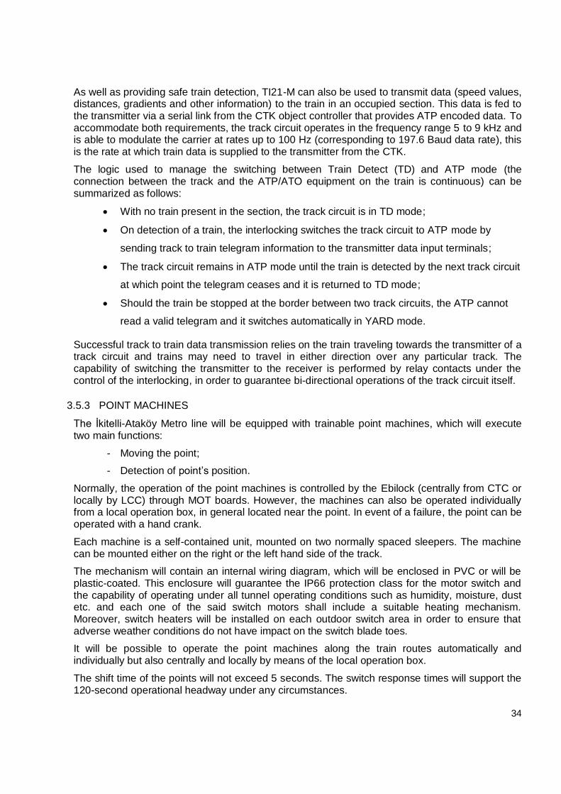
The general Balise is the device, which shall transfer wayside data to a passing vehicle.
The Balise is placed in the track, between the two rails (Figure 3.23).
Figure 3.23 - An example showing Balises installed on the track
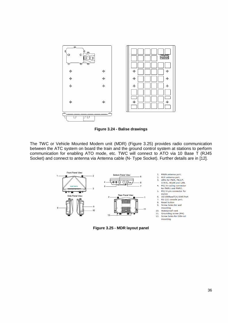
There are two types of Balises (Figure 3.24):
The fixed Balises are used on the line and as Precision Stop Markers (PSM) in order to allow the train to understand its position with a very high precision. They are placed besides platforms and on the approach to stations. They need no cables and be read by onboard ATO as position references for the platform stopping.
The Controlled Balises are managed by an interlocking system and are installed in the
depot beside signals to achieve ATP train trip in case of red signal passing.
The communication between the vehicle antenna and the Balise is based on inductive coupling. The vehicle antenna mounted underneath the front vehicle transmits a signal with a frequency of 27 MHz in order to power up the Balise electronics. The information from the Balise to the vehicle is sent at a rate of 50 kHz by means of 4.5 MHz bursts.
3.5.5 TWC ACCESS POINTS
The TWC equipment in stations consists of Wifi access points installed so as to give coverage to the train units prior to their arrival at the station, thus maximizing the time available for the transfer of data. This equipment is connected to the corporate network by a dedicated pair of fiber optics. The access points work in a frequency range subdivided into several channels, allowing more than one client to become associated to the access point. The technology used is MOXA.
36
Figure 3.24 - Balise drawings
The TWC or Vehicle Mounted Modem unit (MDR) (Figure 3.25) provides radio communication between the ATC system on board the train and the ground control system at stations to perform communication for enabling ATO mode, etc. TWC will connect to ATO via 10 Base T (RJ45 Socket) and connect to antenna via Antenna cable (N- Type Socket). Further details are in [12].
Figure 3.25 - MDR layout panel
37
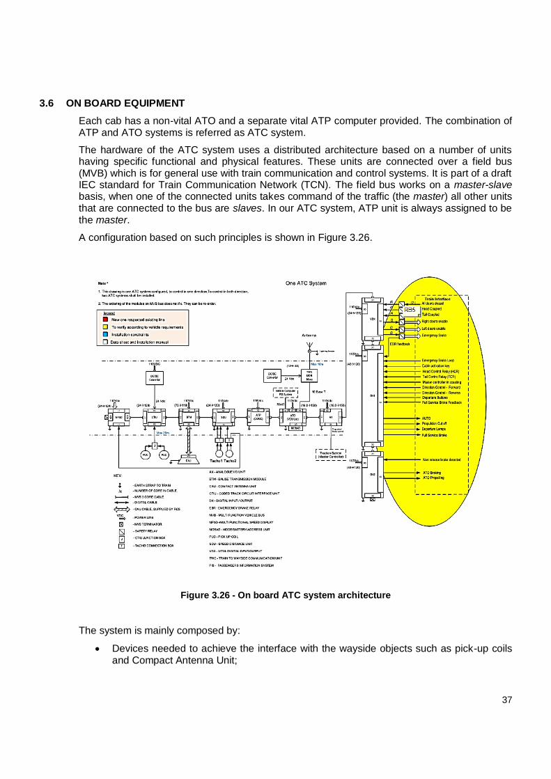
3.6 ON BOARD EQUIPMENT
Each cab has a non-vital ATO and a separate vital ATP computer provided. The combination of ATP and ATO systems is referred as ATC system.
The hardware of the ATC system uses a distributed architecture based on a number of units having specific functional and physical features. These units are connected over a field bus (MVB) which is for general use with train communication and control systems. It is part of a draft IEC standard for Train Communication Network (TCN). The field bus works on a master-slave basis, when one of the connected units takes command of the traffic (the master) all other units that are connected to the bus are slaves. In our ATC system, ATP unit is always assigned to be the master.
A configuration based on such principles is shown in Figure 3.26.
Figure 3.26 - On board ATC system architecture
The system is mainly composed by:
Devices needed to achieve the interface with the wayside objects such as pick-up coils and Compact Antenna Unit;
38
Devices such as I/O units used to collect all the information provided by the Interlocking and concerning the vehicle;
Devices such as computer units used to elaborate all the information provided by the interlocking and concerning the vehicle;
A Multi-Functional Speed Display (MFSD) located in the cabin at the driver desk, where all the driving relevant information is clearly presented to the driver.
The scheme reported above shows the interface with the trains running on the existing line. It could be subject to update once new trains architecture specification will be available.
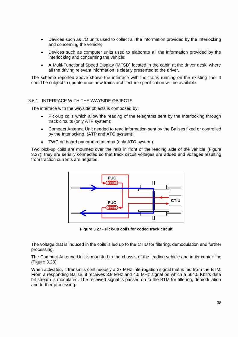
3.6.1 INTERFACE WITH THE WAYSIDE OBJECTS
The interface with the wayside objects is composed by:
Pick-up coils which allow the reading of the telegrams sent by the Interlocking through track circuits (only ATP system);
Compact Antenna Unit needed to read information sent by the Balises fixed or controlled by the Interlocking. (ATP and ATO system);
TWC on board panorama antenna (only ATO system).
Two pick-up coils are mounted over the rails in front of the leading axle of the vehicle (Figure 3.27); they are serially connected so that track circuit voltages are added and voltages resulting from traction currents are negated.
CTIUPUC
PUC
Figure 3.27 - Pick-up coils for coded track circuit
The voltage that is induced in the coils is led up to the CTIU for filtering, demodulation and further processing.
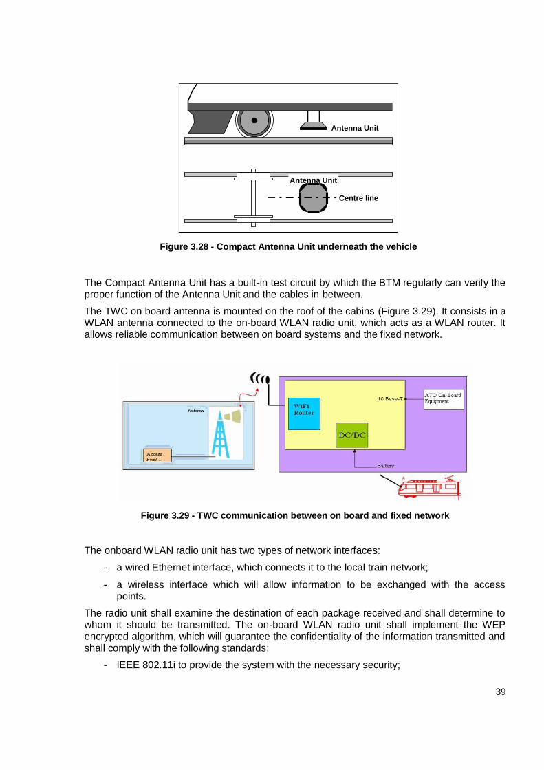
The Compact Antenna Unit is mounted to the chassis of the leading vehicle and in its center line (Figure 3.28).
When activated, it transmits continuously a 27 MHz interrogation signal that is fed from the BTM. From a responding Balise, it receives 3.9 MHz and 4.5 MHz signal on which a 564.5 Kbit/s data bit stream is modulated. The received signal is passed on to the BTM for filtering, demodulation and further processing.
39
Antenna Unit
Centre line
Antenna Unit
Figure 3.28 - Compact Antenna Unit underneath the vehicle
The Compact Antenna Unit has a built-in test circuit by which the BTM regularly can verify the proper function of the Antenna Unit and the cables in between.
The TWC on board antenna is mounted on the roof of the cabins (Figure 3.29). It consists in a WLAN antenna connected to the on-board WLAN radio unit, which acts as a WLAN router. It allows reliable communication between on board systems and the fixed network.
Figure 3.29 - TWC communication between on board and fixed network
The onboard WLAN radio unit has two types of network interfaces:
- a wired Ethernet interface, which connects it to the local train network;
- a wireless interface which will allow information to be exchanged with the access points.
The radio unit shall examine the destination of each package received and shall determine to whom it should be transmitted. The on-board WLAN radio unit shall implement the WEP encrypted algorithm, which will guarantee the confidentiality of the information transmitted and shall comply with the following standards:
- IEEE 802.11i to provide the system with the necessary security;
40
- IEEE 802.1x for authentication;
- IEEE 802.11e for the implementation of service quality.
More detailed information is the relevant Functional Design Specification documents [12].
3.6.2 I/O UNITS
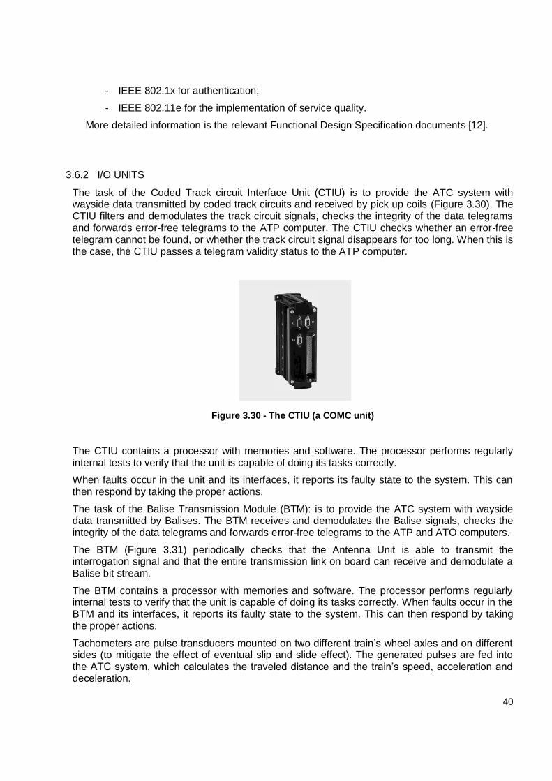
The task of the Coded Track circuit Interface Unit (CTIU) is to provide the ATC system with wayside data transmitted by coded track circuits and received by pick up coils (Figure 3.30). The CTIU filters and demodulates the track circuit signals, checks the integrity of the data telegrams and forwards error-free telegrams to the ATP computer. The CTIU checks whether an error-free telegram cannot be found, or whether the track circuit signal disappears for too long. When this is the case, the CTIU passes a telegram validity status to the ATP computer.
Figure 3.30 - The CTIU (a COMC unit)
The CTIU contains a processor with memories and software. The processor performs regularly internal tests to verify that the unit is capable of doing its tasks correctly.
When faults occur in the unit and its interfaces, it reports its faulty state to the system. This can then respond by taking the proper actions.
The task of the Balise Transmission Module (BTM): is to provide the ATC system with wayside data transmitted by Balises. The BTM receives and demodulates the Balise signals, checks the integrity of the data telegrams and forwards error-free telegrams to the ATP and ATO computers.
The BTM (Figure 3.31) periodically checks that the Antenna Unit is able to transmit the interrogation signal and that the entire transmission link on board can receive and demodulate a Balise bit stream.
The BTM contains a processor with memories and software. The processor performs regularly internal tests to verify that the unit is capable of doing its tasks correctly. When faults occur in the BTM and its interfaces, it reports its faulty state to the system. This can then respond by taking the proper actions.
Tachometers are pulse transducers mounted on two different train’s wheel axles and on different sides (to mitigate the effect of eventual slip and slide effect). The generated pulses are fed into the ATC system, which calculates the traveled distance and the train’s speed, acceleration and deceleration.
41
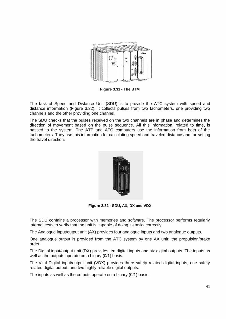
Figure 3.31 - The BTM
The task of Speed and Distance Unit (SDU) is to provide the ATC system with speed and distance information (Figure 3.32). It collects pulses from two tachometers, one providing two channels and the other providing one channel.
The SDU checks that the pulses received on the two channels are in phase and determines the direction of movement based on the pulse sequence. All this information, related to time, is passed to the system. The ATP and ATO computers use the information from both of the tachometers. They use this information for calculating speed and traveled distance and for setting the travel direction.
Figure 3.32 - SDU, AX, DX and VDX
The SDU contains a processor with memories and software. The processor performs regularly internal tests to verify that the unit is capable of doing its tasks correctly.
The Analogue input/output unit (AX) provides four analogue inputs and two analogue outputs.
One analogue output is provided from the ATC system by one AX unit: the propulsion/brake order.
The Digital input/output unit (DX) provides ten digital inputs and six digital outputs. The inputs as well as the outputs operate on a binary (0/1) basis.
The Vital Digital input/output unit (VDX) provides three safety related digital inputs, one safety related digital output, and two highly reliable digital outputs.
The inputs as well as the outputs operate on a binary (0/1) basis.
42
Three vital digital inputs are provided to the ATC system by one VDX unit:
All doors closed;
Head Coupled;
Tail Coupled.
Moreover, three vital digital outputs are provided to the ATC system by one VDX unit:
Emergency brake;
Left door enables;
Right door enables.
3.6.3 COMPUTER UNITS
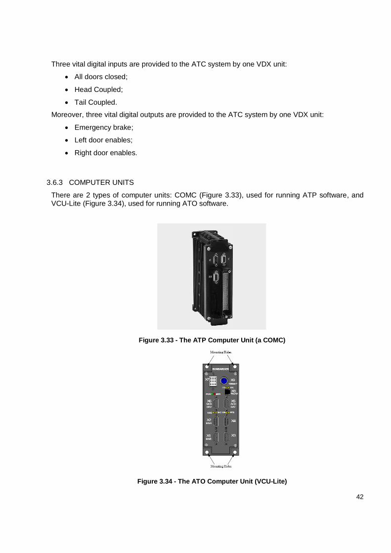
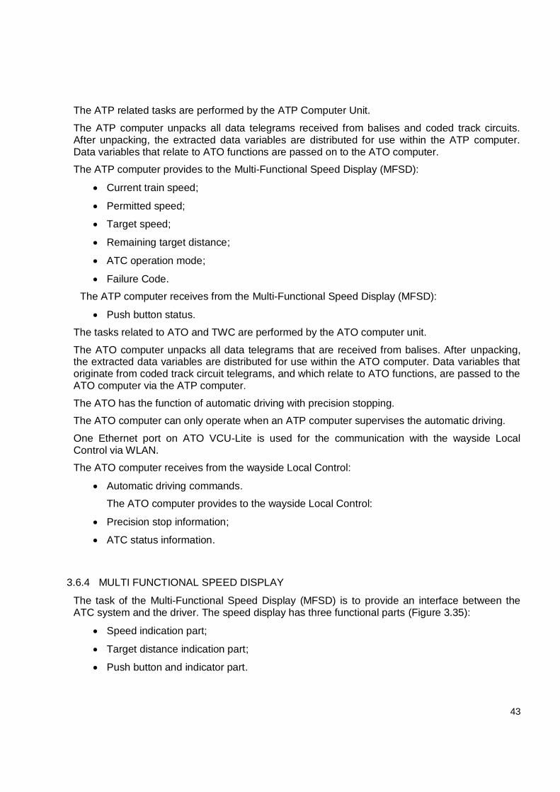
There are 2 types of computer units: COMC (Figure 3.33), used for running ATP software, and VCU-Lite (Figure 3.34), used for running ATO software.
Figure 3.33 - The ATP Computer Unit (a COMC)
Figure 3.34 - The ATO Computer Unit (VCU-Lite)
43
The ATP related tasks are performed by the ATP Computer Unit.
The ATP computer unpacks all data telegrams received from balises and coded track circuits. After unpacking, the extracted data variables are distributed for use within the ATP computer. Data variables that relate to ATO functions are passed on to the ATO computer.
The ATP computer provides to the Multi-Functional Speed Display (MFSD):
Current train speed;
Permitted speed;
Target speed;
Remaining target distance;
ATC operation mode;
Failure Code.
The ATP computer receives from the Multi-Functional Speed Display (MFSD):
Push button status.
The tasks related to ATO and TWC are performed by the ATO computer unit.
The ATO computer unpacks all data telegrams that are received from balises. After unpacking, the extracted data variables are distributed for use within the ATO computer. Data variables that originate from coded track circuit telegrams, and which relate to ATO functions, are passed to the ATO computer via the ATP computer.
The ATO has the function of automatic driving with precision stopping.
The ATO computer can only operate when an ATP computer supervises the automatic driving.
One Ethernet port on ATO VCU-Lite is used for the communication with the wayside Local Control via WLAN.
The ATO computer receives from the wayside Local Control:
Automatic driving commands.
The ATO computer provides to the wayside Local Control:
Precision stop information;
ATC status information.
3.6.4 MULTI FUNCTIONAL SPEED DISPLAY
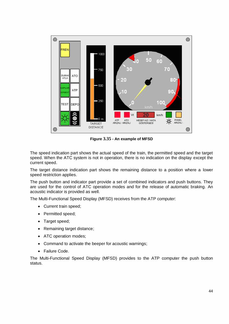
The task of the Multi-Functional Speed Display (MFSD) is to provide an interface between the ATC system and the driver. The speed display has three functional parts (Figure 3.35):
Speed indication part;
Target distance indication part;
Push button and indicator part.
44
Figure 3.35 - An example of MFSD
The speed indication part shows the actual speed of the train, the permitted speed and the target speed. When the ATC system is not in operation, there is no indication on the display except the current speed.
The target distance indication part shows the remaining distance to a position where a lower speed restriction applies.
The push button and indicator part provide a set of combined indicators and push buttons. They are used for the control of ATC operation modes and for the release of automatic braking. An acoustic indicator is provided as well.
The Multi-Functional Speed Display (MFSD) receives from the ATP computer:
Current train speed;
Permitted speed;
Target speed;
Remaining target distance;
ATC operation modes;
Command to activate the beeper for acoustic warnings;
Failure Code.
The Multi-Functional Speed Display (MFSD) provides to the ATP computer the push button status.
45
3.7 INTERFACED SYSTEMS
The İkitelli-Ataköy Metro section will interface with the same external systems of the Metrokent-Olimpiyat-Kirazlı Metro, among which are:
Central master clock;
Passenger information system;
Transmission system;
Vehicles.
In addition, new interfaces will be implemented for the following systems.
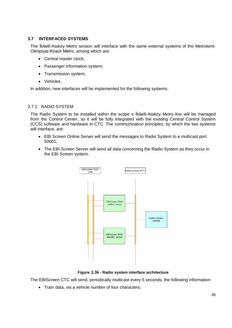
3.7.1 RADIO SYSTEM
The Radio System to be installed within the scope o İkitelli-Ataköy Metro line will be managed from the Control Center, so it will be fully integrated with the existing Central Control System (CCS) software and hardware in CTC. The communication principles, by which the two systems will interface, are:
EBI Screen Online Server will send the messages to Radio System to a multicast port 50001;
The EBI Screen Server will send all data concerning the Radio System as they occur in the EBI Screen system.
Figure 3.36 - Radio system interface architecture
The EBIScreen CTC will send, periodically multicast every 5 seconds, the following information:
Train data, via a vehicle number of four characters;
46
Train describer, via a unique train identifier of five characters: the first char (D) is the train direction; the next two characters (SS) denote the terminal destination turn-back station; the next two characters (NN) display the current Train Run.
The occupied track circuit ID in order to communicate the train location.
3.7.2 EARTHQUAKE EARLY WARNING SYSTEM
The Signaling System is designed with features that enable automatic stop of all trains operating on the line by means of a warning to be made to the Operator, in case seismic information are provided to it from the systems such as Earthquake Early Warning System in the following phases. The two systems will interface through the vital input channel of a dedicated CCM-E board.
3.7.3 SCADA/ETC SYSTEM INTERFACE
New interface will be implemented with the SCADA/ETC system to monitor the signaling UPSs and the catenary status. The info will pass through a CCM-E and then displayed and handled by the EBIScreen 2000 of the CTC/LCSS.
47
4. FUNCTIONALITIES
4.1 CENTRALISED TRAFFIC CONTROL (CTC)
4.1.1 BASIC FUNCTIONS
As told in advance in the architecture description, the basic function of the CTC is the supervision and control of the whole line managed by Ebilock, that is:
Collecting all the information about the field object status coming from the Ebilock. For instance: an open circuit caused by an occupied track circuit, the position of a point;
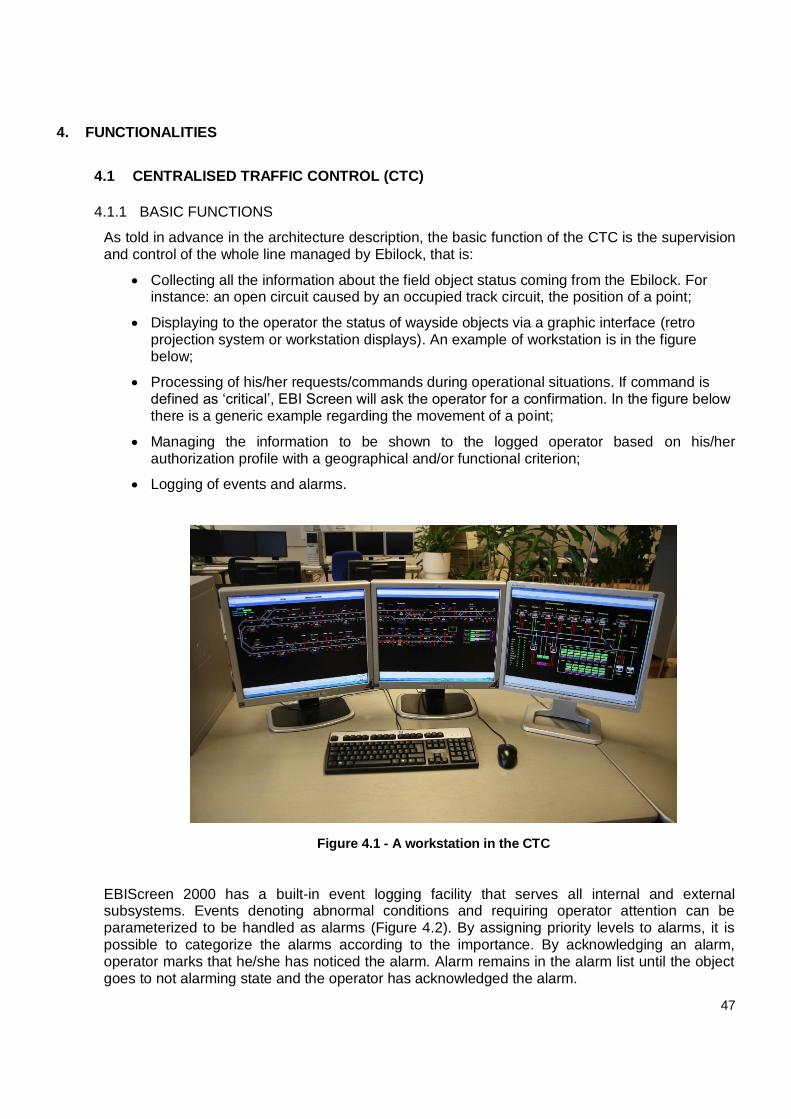
Displaying to the operator the status of wayside objects via a graphic interface (retro projection system or workstation displays). An example of workstation is in the figure below;
Processing of his/her requests/commands during operational situations. If command is defined as ‘critical’, EBI Screen will ask the operator for a confirmation. In the figure below there is a generic example regarding the movement of a point;
Managing the information to be shown to the logged operator based on his/her authorization profile with a geographical and/or functional criterion;
Logging of events and alarms.
Figure 4.1 - A workstation in the CTC
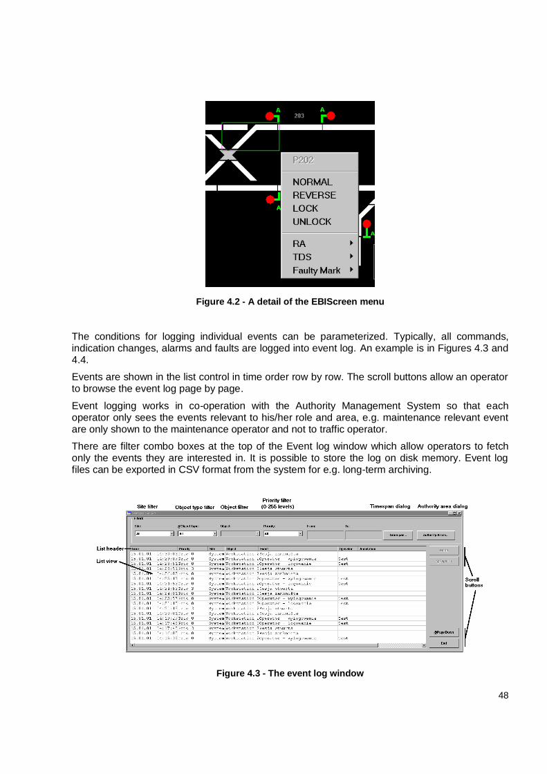
EBIScreen 2000 has a built-in event logging facility that serves all internal and external subsystems. Events denoting abnormal conditions and requiring operator attention can be parameterized to be handled as alarms (Figure 4.2). By assigning priority levels to alarms, it is possible to categorize the alarms according to the importance. By acknowledging an alarm, operator marks that he/she has noticed the alarm. Alarm remains in the alarm list until the object goes to not alarming state and the operator has acknowledged the alarm.
48
Figure 4.2 - A detail of the EBIScreen menu
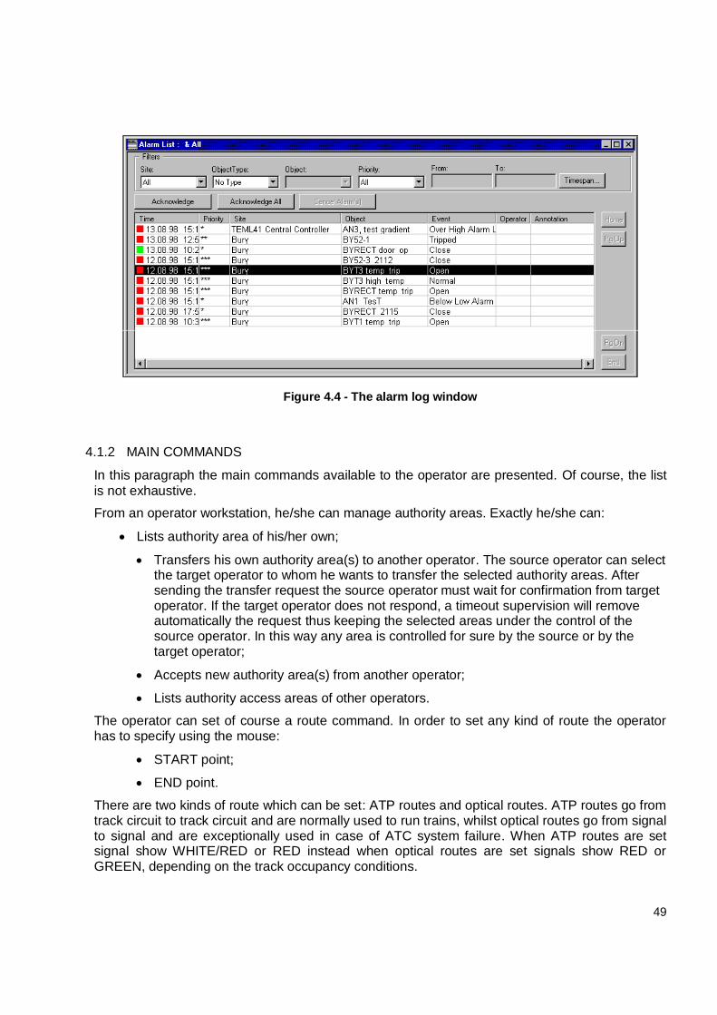
The conditions for logging individual events can be parameterized. Typically, all commands, indication changes, alarms and faults are logged into event log. An example is in Figures 4.3 and 4.4.
Events are shown in the list control in time order row by row. The scroll buttons allow an operator to browse the event log page by page.
Event logging works in co-operation with the Authority Management System so that each operator only sees the events relevant to his/her role and area, e.g. maintenance relevant event are only shown to the maintenance operator and not to traffic operator.
There are filter combo boxes at the top of the Event log window which allow operators to fetch only the events they are interested in. It is possible to store the log on disk memory. Event log files can be exported in CSV format from the system for e.g. long-term archiving.
Figure 4.3 - The event log window
49
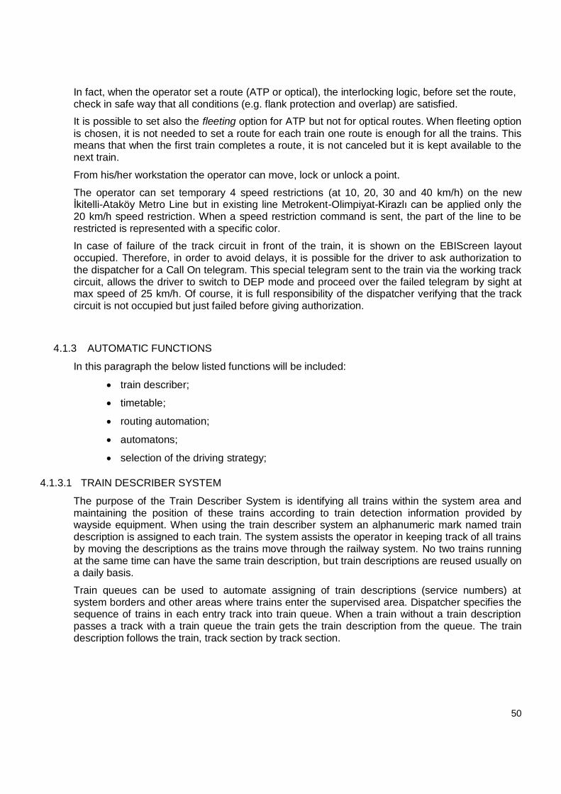
Figure 4.4 - The alarm log window
4.1.2 MAIN COMMANDS
In this paragraph the main commands available to the operator are presented. Of course, the list
is not exhaustive.
From an operator workstation, he/she can manage authority areas. Exactly he/she can:
Lists authority area of his/her own;
Transfers his own authority area(s) to another operator. The source operator can select the target operator to whom he wants to transfer the selected authority areas. After sending the transfer request the source operator must wait for confirmation from target operator. If the target operator does not respond, a timeout supervision will remove automatically the request thus keeping the selected areas under the control of the source operator. In this way any area is controlled for sure by the source or by the target operator;
Accepts new authority area(s) from another operator;
Lists authority access areas of other operators.
The operator can set of course a route command. In order to set any kind of route the operator has to specify using the mouse:
START point;
END point.
There are two kinds of route which can be set: ATP routes and optical routes. ATP routes go from track circuit to track circuit and are normally used to run trains, whilst optical routes go from signal to signal and are exceptionally used in case of ATC system failure. When ATP routes are set signal show WHITE/RED or RED instead when optical routes are set signals show RED or GREEN, depending on the track occupancy conditions.
50
In fact, when the operator set a route (ATP or optical), the interlocking logic, before set the route, check in safe way that all conditions (e.g. flank protection and overlap) are satisfied.
It is possible to set also the fleeting option for ATP but not for optical routes. When fleeting option
is chosen, it is not needed to set a route for each train one route is enough for all the trains. This means that when the first train completes a route, it is not canceled but it is kept available to the next train.
From his/her workstation the operator can move, lock or unlock a point.
The operator can set temporary 4 speed restrictions (at 10, 20, 30 and 40 km/h) on the new İkitelli-Ataköy Metro Line but in existing line Metrokent-Olimpiyat-Kirazlı can be applied only the 20 km/h speed restriction. When a speed restriction command is sent, the part of the line to be restricted is represented with a specific color.
In case of failure of the track circuit in front of the train, it is shown on the EBIScreen layout occupied. Therefore, in order to avoid delays, it is possible for the driver to ask authorization to the dispatcher for a Call On telegram. This special telegram sent to the train via the working track circuit, allows the driver to switch to DEP mode and proceed over the failed telegram by sight at max speed of 25 km/h. Of course, it is full responsibility of the dispatcher verifying that the track circuit is not occupied but just failed before giving authorization.
4.1.3 AUTOMATIC FUNCTIONS
In this paragraph the below listed functions will be included:
train describer;
timetable;
routing automation;
automatons;
selection of the driving strategy;
4.1.3.1 TRAIN DESCRIBER SYSTEM
The purpose of the Train Describer System is identifying all trains within the system area and maintaining the position of these trains according to train detection information provided by wayside equipment. When using the train describer system an alphanumeric mark named train description is assigned to each train. The system assists the operator in keeping track of all trains by moving the descriptions as the trains move through the railway system. No two trains running at the same time can have the same train description, but train descriptions are reused usually on a daily basis.
Train queues can be used to automate assigning of train descriptions (service numbers) at system borders and other areas where trains enter the supervised area. Dispatcher specifies the sequence of trains in each entry track into train queue. When a train without a train description passes a track with a train queue the train gets the train description from the queue. The train description follows the train, track section by track section.
51
The train-tracking works in spite of single indication failures. Even if a track section does not work or if the indications from points show them to be in the wrong position, the train description follows the train as correctly as possible. Trains, which pass a signal showing the stop aspect, will be also tracked, and when this and other abnormalities occur, the operator is informed through alarms. Trains with a train description are kept, even if they cannot be tracked because the information from a track section is faulty. When there are new occupations for that train, the train descriptions are picked up again, if possible.
4.1.3.2 TIMETABLES
Timetables provide the primary source of information for the automatic control of train movements through the traffic day. Definitions in the timetable are used as base timing and routing information for decision making relating to train operations. EBI Screen 2000 Timetable Management System works in co-operation with other EBI Screen 2000 subsystems (described in more detail in the following chapters) such as Train Describer system, Routing Automation and Passenger Information.
The timetable management foresees the offline preparation of the seasonal timetable with all the exceptions (holidays, Sundays, etc.), plus the possibility for the operator to modify it online, following the changing needs of train traffic.
Timetable management consists of the following components:
Static Timetable: it is possible to do a long-term planning by using periodic schedules. The operator can create a code for each different traffic scenarios and assign a code to each day within the specified date range. See an example in the figure below (Figure 4.5);
Timetable Builder: it is a tool to manage static timetable data;
Operational Timetable: it is selected for the on-line operation for a certain day. The Operational Timetable usually is loaded for two days, the current day and the next day. Once it is loaded, the operator is able to modify it with the run-time tool Timetable Editor;
Timetable Editor: a tool to manage the operational timetable on-line;
Timetable Loader: it prepares operational timetables from the static timetable data. The Timetable Loader has the following main functions:
Delete the previous operational timetables (yesterday or older);
Create the next operational timetable (tomorrow).
The Timetable Loader is activated daily at a configurable point of time. In exceptional situations, the operator can invoke it manually at any time.
4.1.3.3 AUTOMATIC ROUTE SETTING: ROUTING AUTOMATIONS AND AUTOMATONS
The intention of the automatic route setting is to relieve the operators from their routine routing tasks so that they can devote their work to more unusual situations that may arise. The system is able to generate the route setting commands itself based on knowledge of how the trains proceed through the system.
The facilities included by EBIScreen 2000 for automatic route setting are Routing Automation and Automaton.
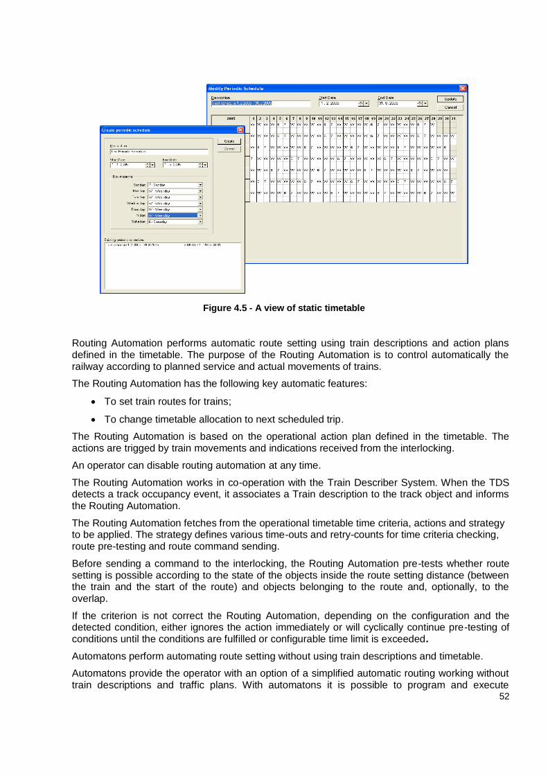
52
Figure 4.5 - A view of static timetable
Routing Automation performs automatic route setting using train descriptions and action plans defined in the timetable. The purpose of the Routing Automation is to control automatically the railway according to planned service and actual movements of trains.
The Routing Automation has the following key automatic features:
To set train routes for trains;
To change timetable allocation to next scheduled trip.
The Routing Automation is based on the operational action plan defined in the timetable. The actions are trigged by train movements and indications received from the interlocking.
An operator can disable routing automation at any time.
The Routing Automation works in co-operation with the Train Describer System. When the TDS detects a track occupancy event, it associates a Train description to the track object and informs the Routing Automation.
The Routing Automation fetches from the operational timetable time criteria, actions and strategy to be applied. The strategy defines various time-outs and retry-counts for time criteria checking, route pre-testing and route command sending.
Before sending a command to the interlocking, the Routing Automation pre-tests whether route setting is possible according to the state of the objects inside the route setting distance (between the train and the start of the route) and objects belonging to the route and, optionally, to the overlap.
If the criterion is not correct the Routing Automation, depending on the configuration and the detected condition, either ignores the action immediately or will cyclically continue pre-testing of conditions until the conditions are fulfilled or configurable time limit is exceeded.
Automatons perform automating route setting without using train descriptions and timetable.
Automatons provide the operator with an option of a simplified automatic routing working without train descriptions and traffic plans. With automatons it is possible to program and execute
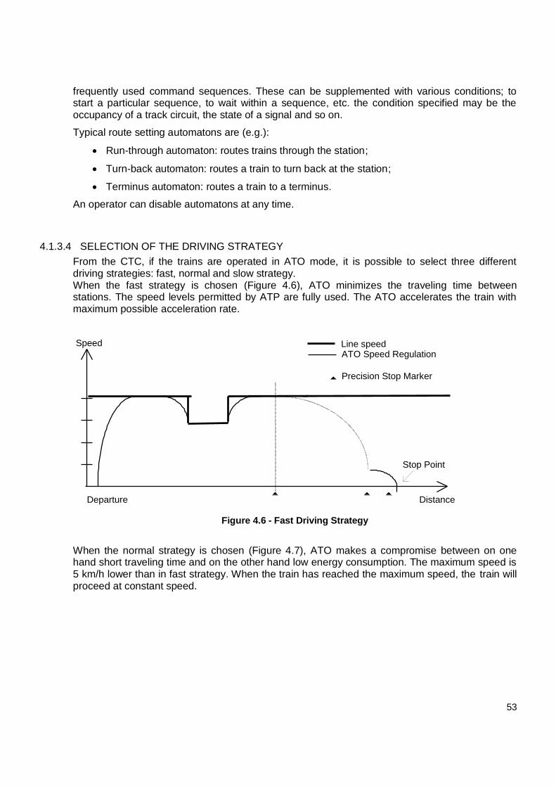
53
frequently used command sequences. These can be supplemented with various conditions; to start a particular sequence, to wait within a sequence, etc. the condition specified may be the occupancy of a track circuit, the state of a signal and so on.
Typical route setting automatons are (e.g.):
Run-through automaton: routes trains through the station;
Turn-back automaton: routes a train to turn back at the station;
Terminus automaton: routes a train to a terminus.
An operator can disable automatons at any time.
4.1.3.4 SELECTION OF THE DRIVING STRATEGY
From the CTC, if the trains are operated in ATO mode, it is possible to select three different driving strategies: fast, normal and slow strategy. When the fast strategy is chosen (Figure 4.6), ATO minimizes the traveling time between stations. The speed levels permitted by ATP are fully used. The ATO accelerates the train with maximum possible acceleration rate.
Speed
Distance
ATO Speed Regulation
Stop Point
Departure
Precision Stop Marker
Line speed
Figure 4.6 - Fast Driving Strategy
When the normal strategy is chosen (Figure 4.7), ATO makes a compromise between on one hand short traveling time and on the other hand low energy consumption. The maximum speed is 5 km/h lower than in fast strategy. When the train has reached the maximum speed, the train will proceed at constant speed.
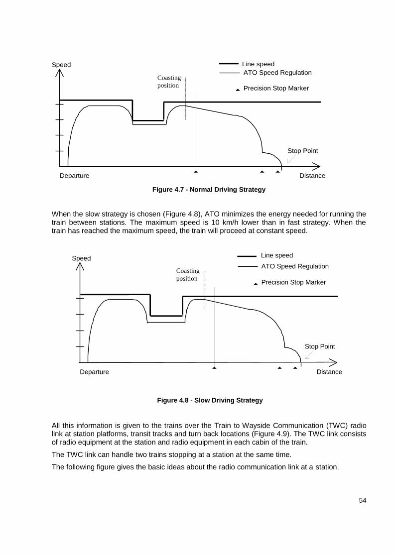
54
Speed
Distance
ATO Speed Regulation
Stop Point
Departure
Precision Stop Marker
Line speed
Coasting
position
Figure 4.7 - Normal Driving Strategy
When the slow strategy is chosen (Figure 4.8), ATO minimizes the energy needed for running the train between stations. The maximum speed is 10 km/h lower than in fast strategy. When the train has reached the maximum speed, the train will proceed at constant speed.
Speed
Distance
ATO Speed Regulation
Stop Point
Departure
Precision Stop Marker
Line speed
Coasting
position
Figure 4.8 - Slow Driving Strategy
All this information is given to the trains over the Train to Wayside Communication (TWC) radio link at station platforms, transit tracks and turn back locations (Figure 4.9). The TWC link consists of radio equipment at the station and radio equipment in each cabin of the train.
The TWC link can handle two trains stopping at a station at the same time.
The following figure gives the basic ideas about the radio communication link at a station.
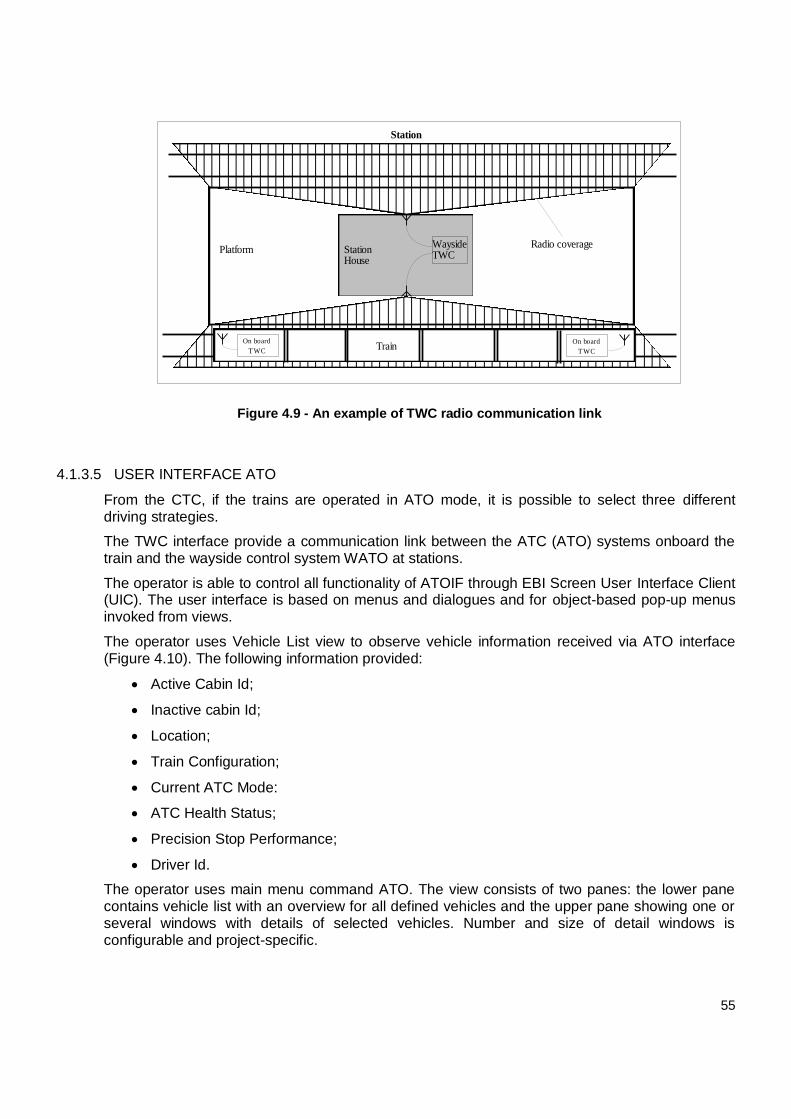
55
PlatformRadio coverage
Train
WaysideTWC
On board
T WC
Station
StationHouse
On board
T WC
Figure 4.9 - An example of TWC radio communication link
4.1.3.5 USER INTERFACE ATO
From the CTC, if the trains are operated in ATO mode, it is possible to select three different driving strategies.
The TWC interface provide a communication link between the ATC (ATO) systems onboard the train and the wayside control system WATO at stations.
The operator is able to control all functionality of ATOIF through EBI Screen User Interface Client (UIC). The user interface is based on menus and dialogues and for object-based pop-up menus invoked from views.
The operator uses Vehicle List view to observe vehicle information received via ATO interface (Figure 4.10). The following information provided:
Active Cabin Id;
Inactive cabin Id;
Location;
Train Configuration;
Current ATC Mode:
ATC Health Status;
Precision Stop Performance;
Driver Id.
The operator uses main menu command ATO. The view consists of two panes: the lower pane contains vehicle list with an overview for all defined vehicles and the upper pane showing one or several windows with details of selected vehicles. Number and size of detail windows is configurable and project-specific.
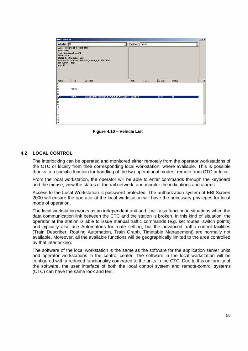
56
Figure 4.10 – Vehicle List
4.2 LOCAL CONTROL
The interlocking can be operated and monitored either remotely from the operator workstations of the CTC or locally from their corresponding local workstation, where available. This is possible thanks to a specific function for handling of the two operational modes, remote from CTC or local.
From the local workstation, the operator will be able to enter commands through the keyboard and the mouse, view the status of the rail network, and monitor the indications and alarms.
Access to the Local Workstation is password protected. The authorization system of EBI Screen 2000 will ensure the operator at the local workstation will have the necessary privileges for local mode of operation.
The local workstation works as an independent unit and it will also function in situations when the data communication link between the CTC and the station is broken. In this kind of situation, the operator at the station is able to issue manual traffic commands (e.g. set routes, switch points) and typically also use Automatons for route setting, but the advanced traffic control facilities (Train Describer, Routing Automation, Train Graph, Timetable Management) are normally not available. Moreover, all the available functions will be geographically limited to the area controlled by that interlocking.
The software of the local workstation is the same as the software for the application server units and operator workstations in the control center. The software in the local workstation will be configured with a reduced functionality compared to the units in the CTC. Due to this uniformity of the software, the user interface of both the local control system and remote-control systems (CTC) can have the same look and feel.
57
4.3 TRAIN SUPERVISION FUNCTIONS (ATP)
4.3.1 TRAIN OPERATION MODES
The train operation modes define the different ways the train can be operated in. They also define where and when the modes are used. There are three different train operation modes, see the definition of ATC Mode.
Apart from the three modes there is the ATC (or ATP) Bypass state in which the ATC is switched off and has no function. Then the TIS displays the speed on the MFSD via the analogue interface of the Speed display unit.
4.3.1.1 YARD (OR DEP) MODE
The train is operated manually by the driver (without ATO). This means that the driver performs the decrease/increase of speed and the door opening/closing. Signals will display G or R aspect but for Call On route also R/W aspect is possible.
In YARD mode the ATP has a reduced supervision and supervises only a fixed ceiling speed of 25 km/h in the forward direction and 5 km/h in the backward direction
YARD mode is normally used:
In the depot (where ATP receives no information from track circuits);
On the line if entering a track circuit, the train loses the telegram;
In case of Call On;
When driving in reverse direction;
After start-up test.
In order to enter YARD mode, the driver is requested to acknowledge the mode change by a flashing YARD indicator/button.
4.3.1.2 MANUAL WITH CAB SIGNALLING (MCS) OR ATP MODE
The ATP system controls the running of train in a safely manner. The relevant information is sent to trains continuously through the equipment along the wayside. The ATP equipped train is operated manually by the driver (without ATO), who follows onboard cab signaling. The information displayed by cab-signaling is consistent with the lineside signaling. This means that the driver performs the decrease/increase of speed using the speed controller. Track signals will display R/W aspect or, in case of optical route G or R aspect.
The ATP checks that the doors are closed before allowing the train to depart. ATP authorizes train departures based on the status of doors (open/closed). If the doors are not detected closed when the train is running the ATP shall let the train run until the driver stops the train. Door enabling is a vital function performed automatically by ATP and it is achieved using information provided by PSM balises about train position. This means that no automatic door enabling is achievable without PSM balises installed on the track.
The driver performs door opening and closing manually.
The ATP has full supervision in MCS mode. The speed supervised is not fixed (as in YARD mode) but is depending on civil speed, target speed and target distance sent to the train by interlocking.
58
In case the driver does not decrease the speed when supposed to according to the Permitted speed indicator, first receives a warning, then the decrease of speed is done automatically by the ATP by first applying the service brake and if this is not sufficient by applying the emergency brake. MCS mode is entered automatically as soon as the ATP finds all conditions for MCS fulfilled. The conditions that must be fulfilled are:
That the ATP receives valid information from the interlocking system via the track circuit;
That the track circuit signals a normal restriction with new datum point before target or
there is a valid datum point.
The ATP issues a service braking order when the train has run a certain distance after the latest
valid telegram was received. In order to proceed the driver needs to acknowledge the change to
DEP mode.
In summary, the ATP system ensures train safety through the functions given below:
Detecting the existence of all trains on the line and in the depot area (including the rail vehicles);
Controlling the actual location of the trains within the tolerance of a track circuit section;
Controlling and regulating train speed on each line section and the implementation of speed limits in trains;
Applying the train brakes in case the speed defined in certain limitations is exceeded;
Controlling the normal running direction;
Protecting the trains from approaching uncontrolled turnouts or turnouts the position of which is not known, closed lines or emergency stop areas, and under certain other dangerous situations;
Monitoring the closing and locking of the doors and authorizing train departures;
Authorizing door opening;
Blocking the door opening in case a train go through a station;
Blocking the door opening in case a train is still moving;
Monitoring the train to enable the train movement and departure on condition that the doors are closed;
Monitoring the stationary state of the train while passengers are getting on and off the train at the station;
Preventing the unauthorized Signal Passed at Danger (SPAD);
Blocking the backward slip when the train starts its movement;
Providing switch internal locking to prevent the moving of a switch while a train crosses over it and to prevent the allowance of the trains into a switch zone unless it is confirmed that the switch is in the correct position and locked;
Monitoring the door closing and locking as well as authorizing train departures;
Checking the PESBs/CESBs and fulfilling their functions;
59
Detection of train consistency violation for 4- and 8-car trains and supervision of train line;
Supervision of alignment, route locking and train movement in connecting and converging route sections.
4.3.1.3 AUTOMATIC TRAIN OPERATION (ATO) OR AUTO MODE
The train is operated automatically with the supervision of the driver that performs some actions, e.g. departing of train, door opening and closing. The driver can enter AUTO mode when the train is at standstill, the ATC system is in MCS mode, the driver’s controllers are in the correct position and communication with CTC is established. AUTO mode has also the function of stopping the train at precision points that is why this mode is not possible without PSM Balises installed on the track.
Currently, the ATO stops trains in the second half of the 180-meters platforms in the direction of operations, regardless trains lengths (4÷8-car sets). However, following the implementation of the new extension and the signaling system update, the Train Stop Position (TSP) of the 4 cars train will be located at 47 m (mid-point) of the 180 m platforms edge (towards the signals). Where the platform is 90 m long (Ikitelli-Atakoy extension), the train will stop at 2 m from the platform edge.
The speed profile followed by the train is the one corresponding to the driving strategy selected from the CTC.
The AUTO mode is selected from a push button in the driver’s panel and it is operated with the direction controller in the neutral position.
It is not usable if ATP system doesn’t work properly.
In summary, the ATP system performs the following functions:
Continuous rail - train communication;
Inspection of the train speed at all line sections;
Inspection of the operational direction in trains with ATP thus ensuring the safety distance between trains without actions by the Control Center operator;
Sending output commands to the train traction system to start the vehicles automatically from the defined automatic stopping points;
Suitable train’s acceleration, deceleration and running on a downhill slope;
Departure control (after the door closing);
Stopping at fixed points along the platforms (stopping precision is ±0.5 m);
Normal stopping using the service brake (electric brake);
Making the passengers doors operative at the station;
Regulation of running time under ATS request;
Normal stopping and starting outside the stations;
Door opening.
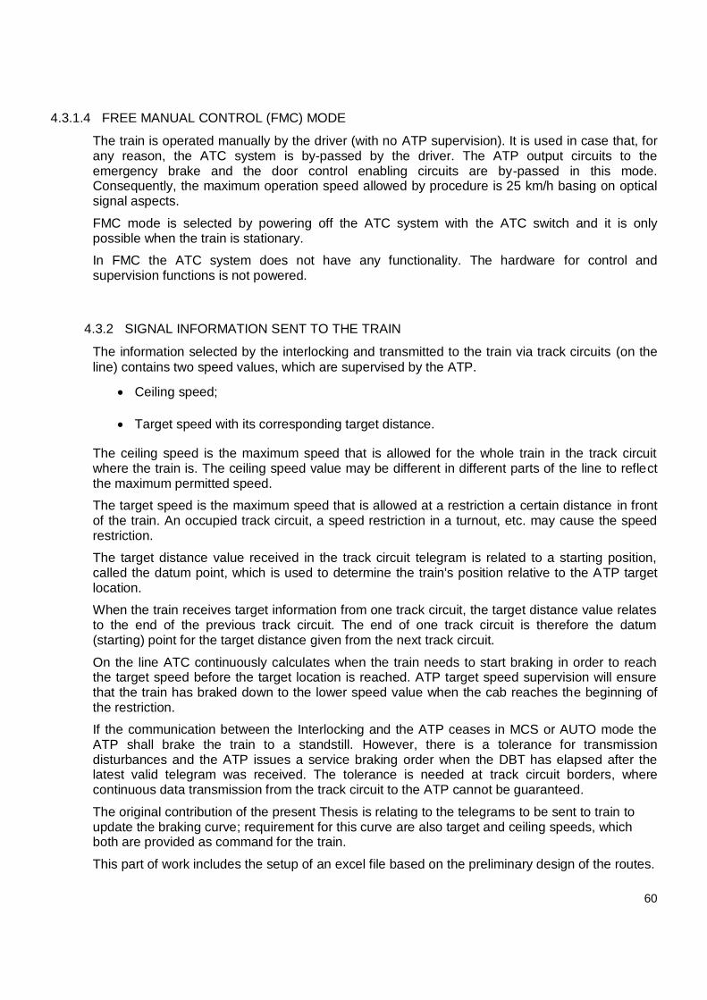
60
4.3.1.4 FREE MANUAL CONTROL (FMC) MODE
The train is operated manually by the driver (with no ATP supervision). It is used in case that, for any reason, the ATC system is by-passed by the driver. The ATP output circuits to the emergency brake and the door control enabling circuits are by-passed in this mode. Consequently, the maximum operation speed allowed by procedure is 25 km/h basing on optical signal aspects.
FMC mode is selected by powering off the ATC system with the ATC switch and it is only possible when the train is stationary.
In FMC the ATC system does not have any functionality. The hardware for control and supervision functions is not powered.
4.3.2 SIGNAL INFORMATION SENT TO THE TRAIN
The information selected by the interlocking and transmitted to the train via track circuits (on the
line) contains two speed values, which are supervised by the ATP.
Ceiling speed;
Target speed with its corresponding target distance.
The ceiling speed is the maximum speed that is allowed for the whole train in the track circuit where the train is. The ceiling speed value may be different in different parts of the line to reflect the maximum permitted speed.
The target speed is the maximum speed that is allowed at a restriction a certain distance in front of the train. An occupied track circuit, a speed restriction in a turnout, etc. may cause the speed restriction.
The target distance value received in the track circuit telegram is related to a starting position, called the datum point, which is used to determine the train's position relative to the ATP target location.
When the train receives target information from one track circuit, the target distance value relates to the end of the previous track circuit. The end of one track circuit is therefore the datum (starting) point for the target distance given from the next track circuit.
On the line ATC continuously calculates when the train needs to start braking in order to reach the target speed before the target location is reached. ATP target speed supervision will ensure that the train has braked down to the lower speed value when the cab reaches the beginning of the restriction.
If the communication between the Interlocking and the ATP ceases in MCS or AUTO mode the ATP shall brake the train to a standstill. However, there is a tolerance for transmission disturbances and the ATP issues a service braking order when the DBT has elapsed after the latest valid telegram was received. The tolerance is needed at track circuit borders, where continuous data transmission from the track circuit to the ATP cannot be guaranteed.
The original contribution of the present Thesis is relating to the telegrams to be sent to train to update the braking curve; requirement for this curve are also target and ceiling speeds, which both are provided as command for the train.
This part of work includes the setup of an excel file based on the preliminary design of the routes.
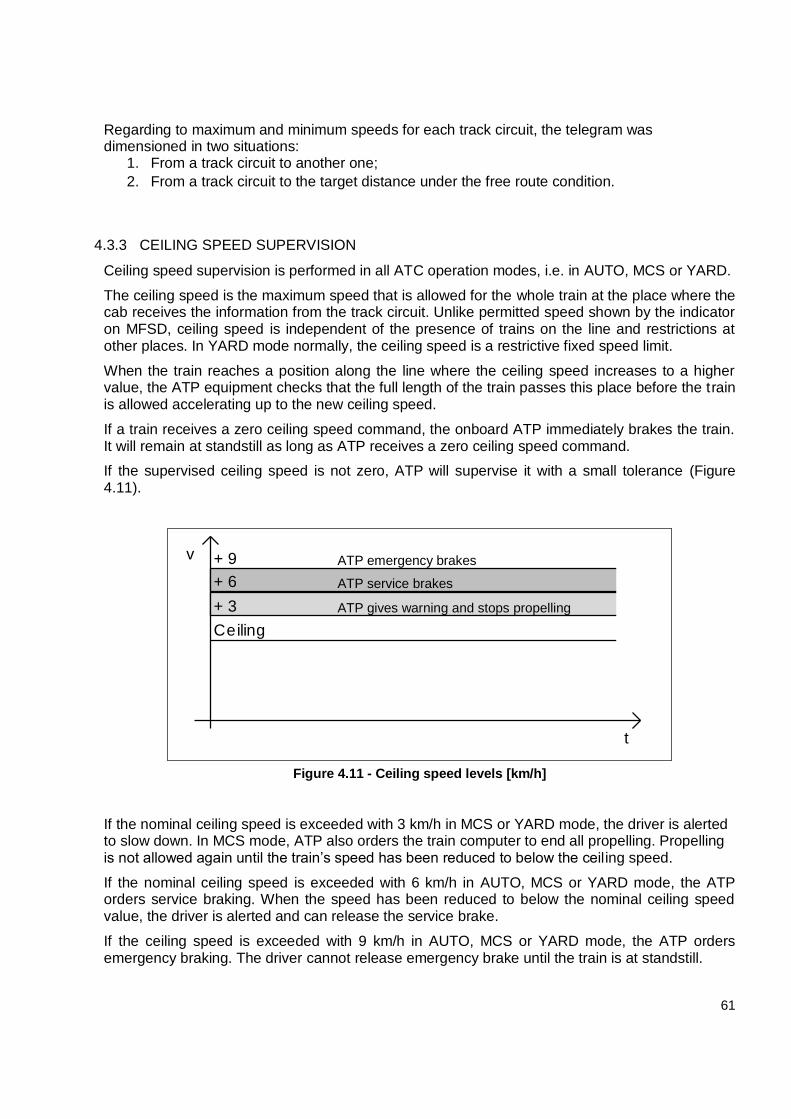
61
Regarding to maximum and minimum speeds for each track circuit, the telegram was dimensioned in two situations:
1. From a track circuit to another one;
2. From a track circuit to the target distance under the free route condition.
4.3.3 CEILING SPEED SUPERVISION
Ceiling speed supervision is performed in all ATC operation modes, i.e. in AUTO, MCS or YARD.
The ceiling speed is the maximum speed that is allowed for the whole train at the place where the cab receives the information from the track circuit. Unlike permitted speed shown by the indicator on MFSD, ceiling speed is independent of the presence of trains on the line and restrictions at other places. In YARD mode normally, the ceiling speed is a restrictive fixed speed limit.
When the train reaches a position along the line where the ceiling speed increases to a higher value, the ATP equipment checks that the full length of the train passes this place before the train is allowed accelerating up to the new ceiling speed.
If a train receives a zero ceiling speed command, the onboard ATP immediately brakes the train. It will remain at standstill as long as ATP receives a zero ceiling speed command.
If the supervised ceiling speed is not zero, ATP will supervise it with a small tolerance (Figure 4.11).
Ceiling
speed
+ 3
km/ h
+ 9
km/ h+ 6
km/ h ATP gives warning and stops propelling
ATP service brakes
ATP emergency brakesv
t
Figure 4.11 - Ceiling speed levels [km/h]
If the nominal ceiling speed is exceeded with 3 km/h in MCS or YARD mode, the driver is alerted to slow down. In MCS mode, ATP also orders the train computer to end all propelling. Propelling is not allowed again until the train’s speed has been reduced to below the ceiling speed.
If the nominal ceiling speed is exceeded with 6 km/h in AUTO, MCS or YARD mode, the ATP orders service braking. When the speed has been reduced to below the nominal ceiling speed value, the driver is alerted and can release the service brake.
If the ceiling speed is exceeded with 9 km/h in AUTO, MCS or YARD mode, the ATP orders emergency braking. The driver cannot release emergency brake until the train is at standstill.
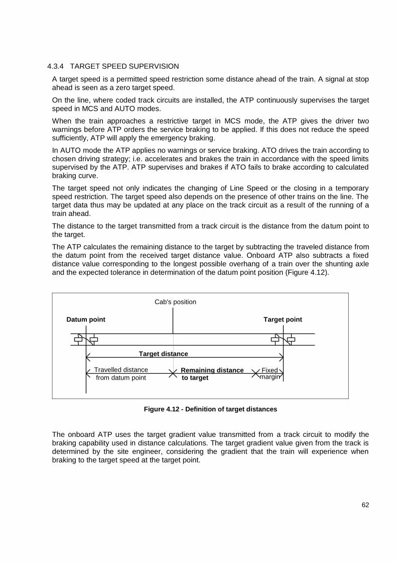
62
4.3.4 TARGET SPEED SUPERVISION
A target speed is a permitted speed restriction some distance ahead of the train. A signal at stop ahead is seen as a zero target speed.
On the line, where coded track circuits are installed, the ATP continuously supervises the target speed in MCS and AUTO modes.
When the train approaches a restrictive target in MCS mode, the ATP gives the driver two warnings before ATP orders the service braking to be applied. If this does not reduce the speed sufficiently, ATP will apply the emergency braking.
In AUTO mode the ATP applies no warnings or service braking. ATO drives the train according to chosen driving strategy; i.e. accelerates and brakes the train in accordance with the speed limits supervised by the ATP. ATP supervises and brakes if ATO fails to brake according to calculated braking curve.
The target speed not only indicates the changing of Line Speed or the closing in a temporary speed restriction. The target speed also depends on the presence of other trains on the line. The target data thus may be updated at any place on the track circuit as a result of the running of a train ahead.
The distance to the target transmitted from a track circuit is the distance from the datum point to the target.
The ATP calculates the remaining distance to the target by subtracting the traveled distance from the datum point from the received target distance value. Onboard ATP also subtracts a fixed distance value corresponding to the longest possible overhang of a train over the shunting axle and the expected tolerance in determination of the datum point position (Figure 4.12).
Target distance
Fixedmargin
Travelled distance
from datum point
Datum point Target point
Remaining distanceto target
Cab's position
Figure 4.12 - Definition of target distances
The onboard ATP uses the target gradient value transmitted from a track circuit to modify the braking capability used in distance calculations. The target gradient value given from the track is determined by the site engineer, considering the gradient that the train will experience when braking to the target speed at the target point.
63
4.3.5 CALCULATION OF WARNING AND BRAKE CURVES
In MCS mode, the warnings and the service braking application is signaled at certain time intervals before ATP must trigger the emergency braking (Figure 4.13):
First driver warning precedes second driver warning of a speed dependent time;
Second driver warning precedes service braking trig of a speed dependent time;
The application of service braking from the ATP precedes emergency braking trig with of a
speed dependent time.
Target distance
Fixedmargin
Travelled distance
from datum point
Datum point Target point
Remaining distanceto target
Emergency brake
Train's speed
Service brake
Second warning
First warning
deceleration curveEmergency brake trig
Figure 4.13 - Braking and warning curves
Thus, the driver is warned at first several seconds before the ATP orders a service braking application.
ATP adjusts the time calculations so that the driver gets the same warning time independently of the line gradient.
In AUTO mode the ATP warnings and service braking is suppressed. Any braking effort needed is handled by the ATO.
If the target point is moved further ahead, i.e. a forward train has left the track circuit ahead of the target point; the ATP recalculates the braking curves. If the distance to the new target point is far away, i.e. the train is in front of the second warning curve; the ATP shall not apply the service braking. In this situation the driver is alerted to release the brakes by a flashing BRK lamp.
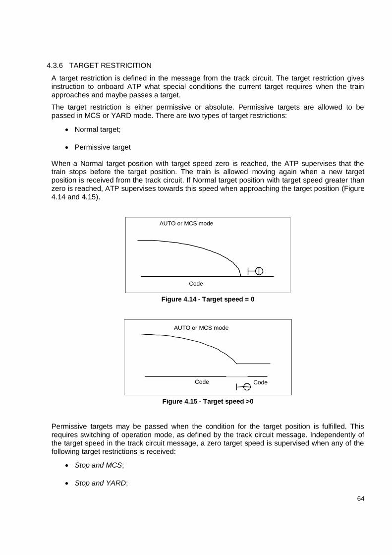
64
4.3.6 TARGET RESTRICITION
A target restriction is defined in the message from the track circuit. The target restriction gives instruction to onboard ATP what special conditions the current target requires when the train approaches and maybe passes a target.
The target restriction is either permissive or absolute. Permissive targets are allowed to be passed in MCS or YARD mode. There are two types of target restrictions:
Normal target;
Permissive target
When a Normal target position with target speed zero is reached, the ATP supervises that the train stops before the target position. The train is allowed moving again when a new target position is received from the track circuit. If Normal target position with target speed greater than zero is reached, ATP supervises towards this speed when approaching the target position (Figure 4.14 and 4.15).
Code
AUTO or MCS mode
Figure 4.14 - Target speed = 0
AUTO or MCS mode
Code Code
Figure 4.15 - Target speed >0
Permissive targets may be passed when the condition for the target position is fulfilled. This requires switching of operation mode, as defined by the track circuit message. Independently of the target speed in the track circuit message, a zero target speed is supervised when any of the following target restrictions is received:
Stop and MCS;
Stop and YARD;
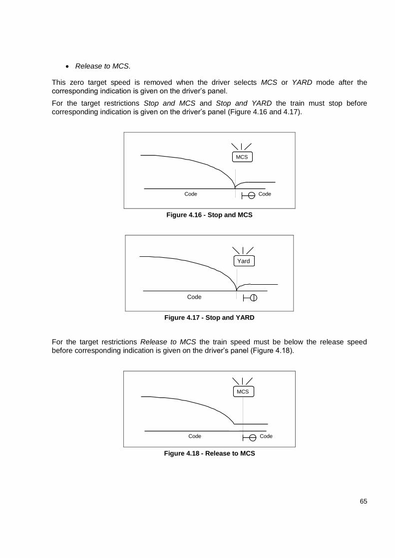
65
Release to MCS.
This zero target speed is removed when the driver selects MCS or YARD mode after the
corresponding indication is given on the driver’s panel.
For the target restrictions Stop and MCS and Stop and YARD the train must stop before
corresponding indication is given on the driver’s panel (Figure 4.16 and 4.17).
Code
MCS
Code
Figure 4.16 - Stop and MCS
Code
Yard
Figure 4.17 - Stop and YARD
For the target restrictions Release to MCS the train speed must be below the release speed
before corresponding indication is given on the driver’s panel (Figure 4.18).
Code Code
MCS
Figure 4.18 - Release to MCS
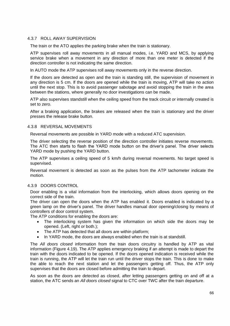
66
4.3.7 ROLL AWAY SUPERVISION
The train or the ATO applies the parking brake when the train is stationary.
ATP supervises roll away movements in all manual modes, i.e. YARD and MCS, by applying service brake when a movement in any direction of more than one meter is detected if the direction controller is not indicating the same direction.
In AUTO mode the ATP supervises roll away movements only in the reverse direction.
If the doors are detected as open and the train is standing still, the supervision of movement in any direction is 5 cm. If the doors are opened while the train is moving, ATP will take no action until the next stop. This is to avoid passenger sabotage and avoid stopping the train in the area between the stations, where generally no door investigations can be made.
ATP also supervises standstill when the ceiling speed from the track circuit or internally created is set to zero.
After a braking application, the brakes are released when the train is stationary and the driver presses the release brake button.
4.3.8 REVERSAL MOVEMENTS
Reversal movements are possible in YARD mode with a reduced ATC supervision.
The driver selecting the reverse position of the direction controller initiates reverse movements. The ATC then starts to flash the YARD mode button on the driver’s panel. The driver selects YARD mode by pushing the YARD button.
The ATP supervises a ceiling speed of 5 km/h during reversal movements. No target speed is supervised.
Reversal movement is detected as soon as the pulses from the ATP tachometer indicate the motion.
4.3.9 DOORS CONTROL
Door enabling is a vital information from the interlocking, which allows doors opening on the correct side of the train. The driver can open the doors when the ATP has enabled it. Doors enabled is indicated by a green lamp on the driver’s panel. The driver handles manual door opening/closing by means of controllers of door control system. The ATP conditions for enabling the doors are:
The interlocking system has given the information on which side the doors may be opened. (Left, right or both.);
The ATP has detected that all doors are within platform;
In YARD mode, the doors are always enabled when the train is at standstill.
The All doors closed information from the train doors circuitry is handled by ATP as vital information (Figure 4.19). The ATP applies emergency braking if an attempt is made to depart the train with the doors indicated to be opened. If the doors opened indication is received while the train is running, the ATP will let the train run until the driver stops the train. This is done to make the able to reach the next station and let the passengers getting off. Thus, the ATP only supervises that the doors are closed before admitting the train to depart.
As soon as the doors are detected as closed, after letting passengers getting on and off at a station, the ATC sends an All doors closed signal to CTC over TWC after the train departure.
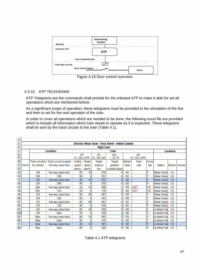
67
ATP
Door Enable/Disable
DoorsDoor Control Signal
Interlocking
SystemWayside
Carborne ATC
Train logic circuits
Figure 4.19 Door control overview.
4.3.10 ATP TELEGRAMS
ATP Telegrams are the commands shall provide for the onboard ATP to make it able for set all operations which are mentioned before.
As a significant scope of operation, these telegrams must be provided to the simulation of the line and then to set for the real operation of the train.
In order to cover all operations which are needed to be done, the following excel file are provided which is include all information which train needs to operate as it is expected. These telegrams shall be sent by the track circuits to the train (Table 4.1).
Table 4.1 ATP telegrams
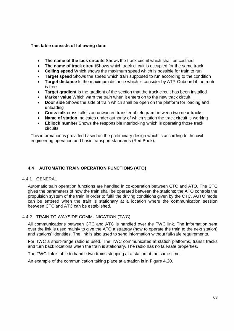
68
This table consists of following data:
The name of the tack circuits Shows the track circuit which shall be codified
The name of track circuitShows which track circuit is occupied for the same track
Ceiling speed Which shows the maximum speed which is possible for train to run
Target speed Shows the speed which train supposed to run according to the condition
Target distance Is the maximum distance which is consider by ATP-Onboard if the route
is free
Target gradient Is the gradient of the section that the track circuit has been installed
Marker value Which warn the train when it enters on to the new track circuit
Door side Shows the side of train which shall be open on the platform for loading and
unloading
Cross talk cross talk is an unwanted transfer of telegram between two near tracks.
Name of station Indicates under authority of which station the track circuit is working
Ebilock number Shows the responsible interlocking which is operating those track
circuits
This information is provided based on the preliminary design which is according to the civil engineering operation and basic transport standards (Red Book).
4.4 AUTOMATIC TRAIN OPERATION FUNCTIONS (ATO)
4.4.1 GENERAL
Automatic train operation functions are handled in co-operation between CTC and ATO. The CTC gives the parameters of how the train shall be operated between the stations; the ATO controls the propulsion system of the train in order to fulfil the driving conditions given by the CTC. AUTO mode can be entered when the train is stationary at a location where the communication session between CTC and ATC can be established.
4.4.2 TRAIN TO WAYSIDE COMMUNICATION (TWC)
All communications between CTC and ATC is handled over the TWC link. The information sent over the link is used mainly to give the ATO a strategy (how to operate the train to the next station) and stations’ identities. The link is also used to send information without fail-safe requirements.
For TWC a short-range radio is used. The TWC communicates at station platforms, transit tracks and turn back locations when the train is stationary. The radio has no fail-safe properties.
The TWC link is able to handle two trains stopping at a station at the same time.
An example of the communication taking place at a station is in Figure 4.20.
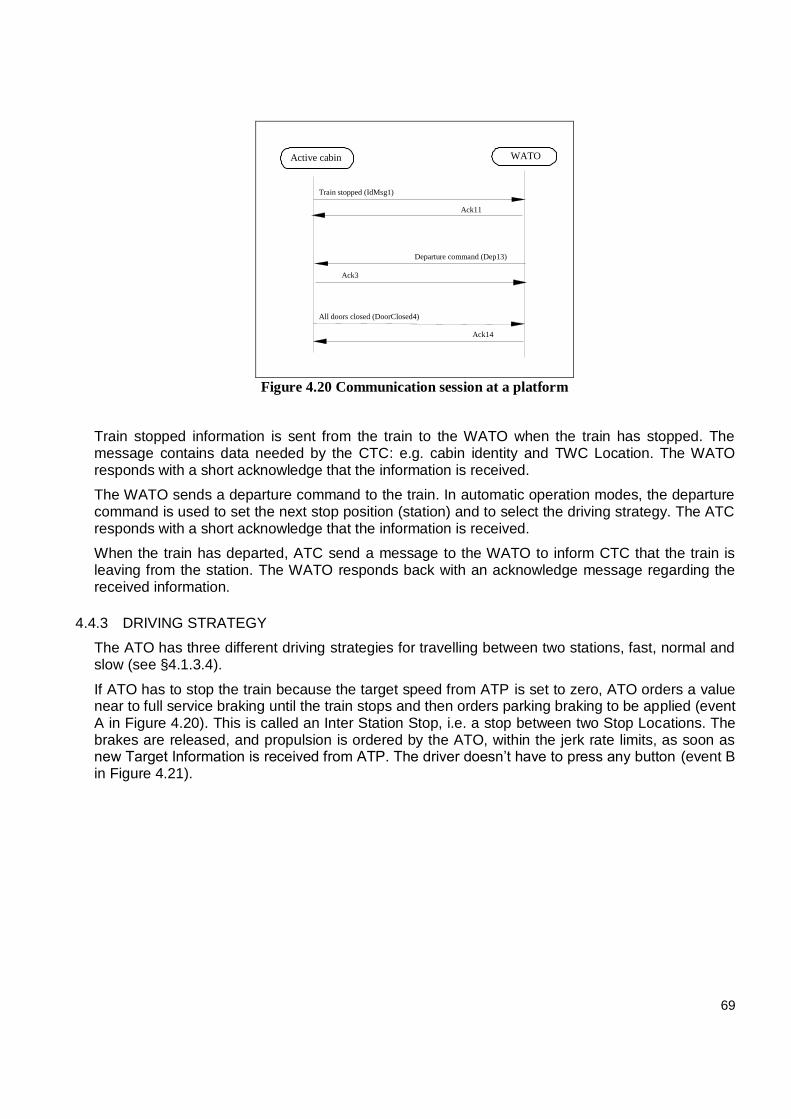
69
Active cabin WATO
Train stopped (IdMsg1)
Ack11
Ack3
Departure command (Dep13)
All doors closed (DoorClosed4)
Ack14
Figure 4.20 Communication session at a platform
Train stopped information is sent from the train to the WATO when the train has stopped. The message contains data needed by the CTC: e.g. cabin identity and TWC Location. The WATO responds with a short acknowledge that the information is received.
The WATO sends a departure command to the train. In automatic operation modes, the departure command is used to set the next stop position (station) and to select the driving strategy. The ATC responds with a short acknowledge that the information is received.
When the train has departed, ATC send a message to the WATO to inform CTC that the train is leaving from the station. The WATO responds back with an acknowledge message regarding the received information.
4.4.3 DRIVING STRATEGY
The ATO has three different driving strategies for travelling between two stations, fast, normal and slow (see §4.1.3.4).
If ATO has to stop the train because the target speed from ATP is set to zero, ATO orders a value near to full service braking until the train stops and then orders parking braking to be applied (event A in Figure 4.20). This is called an Inter Station Stop, i.e. a stop between two Stop Locations. The brakes are released, and propulsion is ordered by the ATO, within the jerk rate limits, as soon as new Target Information is received from ATP. The driver doesn’t have to press any button (event B in Figure 4.21).
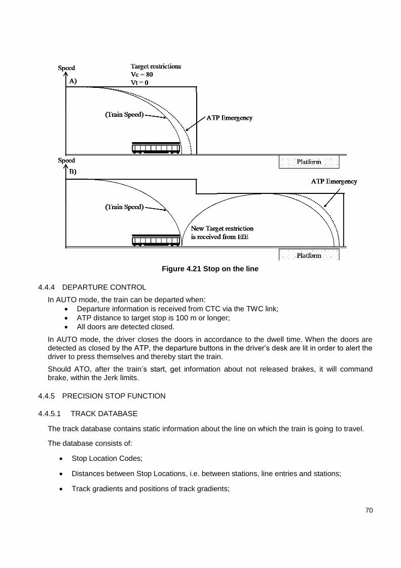
70
Figure 4.21 Stop on the line
4.4.4 DEPARTURE CONTROL
In AUTO mode, the train can be departed when:
Departure information is received from CTC via the TWC link;
ATP distance to target stop is 100 m or longer;
All doors are detected closed.
In AUTO mode, the driver closes the doors in accordance to the dwell time. When the doors are detected as closed by the ATP, the departure buttons in the driver’s desk are lit in order to alert the driver to press themselves and thereby start the train.
Should ATO, after the train’s start, get information about not released brakes, it will command brake, within the Jerk limits.
4.4.5 PRECISION STOP FUNCTION
4.4.5.1 TRACK DATABASE
The track database contains static information about the line on which the train is going to travel.
The database consists of:
Stop Location Codes;
Distances between Stop Locations, i.e. between stations, line entries and stations;
Track gradients and positions of track gradients;
71
Identity, position of PSM’s and the tolerance in position around PSM’s;
Permanent speed restrictions on the track.
The track database handler will supply to the ATO the distance between two stop locations, the track gradients on the line between the stop locations, their exact positions, the identity of the PSM’s, the position of the PSM’s and the range around the PSM’s.
4.4.5.2 PRECISION STOP POINT
Three or four markers, i.e. PSM3, PSM2 and PSM1:2 (and PSM1:1), are used to further correct the position travelled towards the Precision Stop Point at a Stop Location.
The ATO is continuously comparing the train’s current speed against a calculated parabolic velocity and distance profile (Figure 4.22).
Distance
Speed
Stop point
Speed profile one
Speed profile two
Figure 4.22 Precision Stop Curve
As the train moves toward the Precision Stop Point and is about to exceed the calculated speed profile, a continuous braking command is sent to the train control system. The exact position where the braking must start and the magnitude of the braking order depend, apart from current speed, also on track gradient, read from the Track Database. This ensures that braking will always be performed in the most efficient way, i.e. the speed towards the stop position must not be kept unnecessarily low. If there is an ATP stop at the Precision Stop Point, the ATO uses the track gradient sent from the ATP to avoid conflicts with the ATP brake curves, instead of using the gradients in the Track Database.
The brake order will be continuously adjusted in order to follow the calculated speed profile. As the train approaches the Precision Stop Point, a new smoother speed profile will be calculated and used until it is reached. The smoother speed profile will enable the ATO to stop the train in a smooth and precise way.
The regulation algorithm takes into account that the braking behavior at lower speeds is different since the mechanical braking will be further increased and the regenerative motor braking decreased.
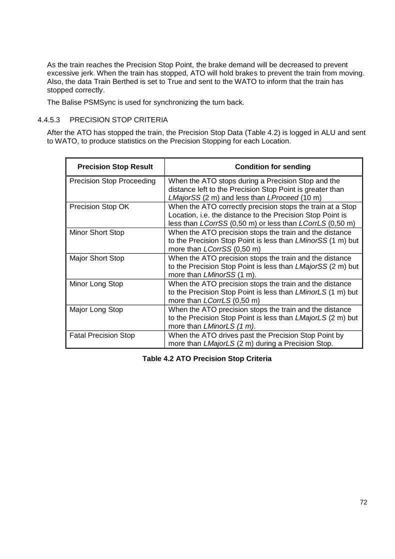
72
As the train reaches the Precision Stop Point, the brake demand will be decreased to prevent excessive jerk. When the train has stopped, ATO will hold brakes to prevent the train from moving. Also, the data Train Berthed is set to True and sent to the WATO to inform that the train has stopped correctly.
The Balise PSMSync is used for synchronizing the turn back.
4.4.5.3 PRECISION STOP CRITERIA
After the ATO has stopped the train, the Precision Stop Data (Table 4.2) is logged in ALU and sent to WATO, to produce statistics on the Precision Stopping for each Location.
Precision Stop Result Condition for sending
Precision Stop Proceeding When the ATO stops during a Precision Stop and the distance left to the Precision Stop Point is greater than LMajorSS (2 m) and less than LProceed (10 m)
Precision Stop OK When the ATO correctly precision stops the train at a Stop Location, i.e. the distance to the Precision Stop Point is less than LCorrSS (0,50 m) or less than LCorrLS (0,50 m)
Minor Short Stop When the ATO precision stops the train and the distance to the Precision Stop Point is less than LMinorSS (1 m) but more than LCorrSS (0,50 m)
Major Short Stop When the ATO precision stops the train and the distance to the Precision Stop Point is less than LMajorSS (2 m) but more than LMinorSS (1 m).
Minor Long Stop When the ATO precision stops the train and the distance to the Precision Stop Point is less than LMinorLS (1 m) but more than LCorrLS (0,50 m)
Major Long Stop When the ATO precision stops the train and the distance to the Precision Stop Point is less than LMajorLS (2 m) but more than LMinorLS (1 m).
Fatal Precision Stop When the ATO drives past the Precision Stop Point by more than LMajorLS (2 m) during a Precision Stop.
Table 4.2 ATO Precision Stop Criteria
73
4.5 EMERGENCY STOP FUNCTION
An emergency stop for each track circuit in each platform can be invoked by:
a. Platform Emergency Stop Buttons (PESB); b. Local Control; c. Central Emergency Stop Buttons (CESB) installed at CTC in a way to be one for each
interlocking zone.
The Local Control or CTC operators are able to invoke an emergency stop via a command on their screen respective of their operating mode (Local/CTC Selection Section)
An emergency stop shall invoke a ceiling speed of zero in the track circuit adjacent to the platform. Therefore, a train outside of this track circuit and outside of its minimum stopping distance shall be supervised to stop at the entrance to the platform track circuit. Trains that are moving and are inside the minimum stopping distance or are actually on the track circuit itself shall be safety braked to stop by the onboard ATP system. If the train is stationary on the track circuit itself the onboard ATP system shall not allow moving it.
74
5. OPERATION
The basic design of the signaling system has been performed considering the following input data and assumptions:
ATO mode is achievable only on normal (right) way;
ATP enables door opening only on normal (right) way (on wrong running side the driver has to use under his own responsibility the appropriate door opening bypass switch);
A dwell time of 20 s at each station for any operational mode, except end stations, where turn-backs are needed;
A headway of 120 s for correct (right) running direction, except degraded modes;
A headway of 180 s for wrong (left) running direction, except degraded modes.
5.1 NORMAL MODES
5.1.1 CENTRAL AUTOMATIC MODE
This is the fully automatic mode normally used to manage the line.
5.1.1.1 FROM THE DISPATCHER POINT OF VIEW
Line
In central automatic mode all routes are set from the CTC.
When a new operational timetable is loaded (usually it is automatic at 3:00 AM, before the traffic starts), he has to assign manually the train descriptions to the train queue according to the loaded timetable.
The trains are moved in/out of the depot from/to the line by manual route commands.
After having left depot, the train occupies the transit track circuit, it is assigned automatically a train description by the train queue. If some trains are parked in the line during the night, they need a manual assignment of train description. Before starting passenger service, the driver has to make sure that his destination matches with the destination assigned automatically by the system, asking for a confirmation to the dispatcher by radio.
All the routes, where no decisions are needed, are set in fleeting mode by central dispatcher. Turn-backs and junction routes, where decisions are needed, will be managed automatically (Automatic route setting or automaton). An operator can disable automatic route setting at any time.
When a route is fleeting, it is not needed to set a route for each train, one route is enough for all the trains. This means that when the first train completes a route, it is not canceled but it is kept available to the next train. Of course, the system supervises safely the distances between two adjacent trains.
The passenger traffic is composed only by ATC equipped trains running in AUTO mode on normal way (right).
Optical routes (from signal to signal) are not needed on the line, instead ATP routes (from track circuit to track circuit) are normally used. All the signals on the line show RED/WHITE or RED aspects.
75
The central dispatcher is not asked to do any routine action.
The central dispatcher is asked just to:
Manage unusual situations as critical commands, alarms etc;
Choose the driving strategy of the trains: fast, normal or slow;
Supervise the movements of the trains;
Modify or load time schedules, if needed.
Depot
Not being foreseen the use of ATP routes, not coded track circuits will be installed in the depot (except test track), thus only optical manual routes (from signal to signal) are available.
The central dispatcher is asked to set manually optical routes.
Signals can show only RED, YELLOW or GREEN aspect.
Only in the two track circuits belonging to the test track, the dispatcher is allowed to set ATP routes for static and limited dynamic tests.
5.1.1.2 FROM THE DRIVER POINT OF VIEW
Line
In central automatic mode, the trains run in AUTO mode. The train automatically follows the speed profile corresponding to the driving strategy selected by the CTC dispatcher and communicated to the ATO via TWC system. The ATO system operates, so that the train driver can initiate departure from all stations.
On the line the driver is asked just to:
Insert destination for each run;
Open the doors (under supervision of ATP);
Close the doors;
Departing the train (just pressing departure buttons).
For train passenger public announcements, the system will be able to provide information about next station, destination and door opening side, except for terminal stations.
Depot
Before entering the depot, the trains will stop and change to YARD mode after a driver acknowledgment. In YARD mode only, a fixed permitted speed of 25 km/h forward and 5 km/h backward is supervised by the ATP on board system. The driver has to control manually the speed of the train using the master controller based on the aspect of signals. The system will supervise just the stop at red signals via controlled Balises installed beside signals: if the train does not stop at red signals, ATP applies emergency brake after passing the Balise controlled by the signal.
Leaving the depot, the on-board system automatically switches in ATP mode and this mode is kept until the first station where, receiving data from TWC access point, it will switch to ATO mode.
76
Entering the depot and in the depot, in DEP mode, the driver has full responsibility to move the train, and here below some of the actions he needs to take:
Control manually the speed;
Stop at red signals;
Open the doors;
Close the doors.
5.1.1.2.1 COUPLING TWO TRAINS
Trains coupling must be done only in Depot area according to the process below.
1. Start coupling, the first train is set to stand still, ATC systems for both cabins are
powered up. No cabin of the first train is activated. Emergency brake of the first train is
applied.
2. Drive carefully the second train in Yard mode to couple the first train. After coupling
finish and ATC get a coupled signal from vehicle, a message code will be displayed on
MFSD showing that head couple signal is active. Inner cabin is automatically
deactivated as soon as coupling is engaged.
3. Once train coupling is completed, tail control relays of both trains will be connected
automatically. The Multiple Unit lamp on the driver desk must be ON. The Emergency
braking of the train is applied, as no cabin is active.
4. Turn off the key switch in the inner cabin, to allow activation of another cabin. Then go to the leading cabin expected to drive the train in operation.
5. Activate the leading cabin, a message code will be displayed on MFSD showing that tail coupled signal is active.
6. Drive the multiple unit to operation.
5.2 DEGRADED MODES
In this section the main subsystem failures are presented with the consequent operational modes to be used.
5.2.1 CTC-INTERLOCKING COMMUNICATION FAILURE (LOCAL MODE)
This mode is used when there is a failure of the CTC - Interlocking communication.
Being not possible the management of the whole traffic from a unique workstation, all the interlocking areas will be managed locally: a local dispatcher is needed at each local workstation in order to supervise and control traffic. In this specific application, 5 local dispatchers are needed at the Local Control Workstation in Metrokent, İkitelli Sanayi, Kirazlı, Olimpiyat, and in the Depot.
It is not possible to use routing automation, train describer but automatons can be used.
From the driver point of view, it is not possible to drive train in ATO mode, so trains have to be run in ATP mode.
77
If only some areas are managed locally and the remaining areas are managed centrally, the trains will run in ATO mode in the area controlled centrally and, entering areas managed locally, the driver will need to switch to ATP mode. Leaving areas managed locally, the driver will switch back to ATO mode.
5.2.2 TWC FAILURE
The TWC system is designed in such a way that in case of any single point of failures the system will automatically converge without any significant consequence by a redundant system.
If there is more than a single point of failure in the TWC subsystem, it is not possible to run trains in AUTO mode. Should the trains before the failure be not running in AUTO mode, there are no consequences. Should the trains be running in AUTO mode, the driver needs to switch to ATP the on-board system. The running of the train is still supervised safely by ATP subsystem.
5.2.3 VIDEOWALL FAILURE
In case of failure of the video wall retro projection modules, the operators keep managing the whole traffic using the monitors of their own workstation. There are no impacts on the operational mode used.
5.2.4 CTC OPERATOR WORKSTATION FAILURE
Three different operator workstations have been foreseen:
during normal traffic hours just one workstation could be used to manage the whole line;
during rush hours two different operators could be needed at two different workstations in order to allow each operator to be focused just on one part of the line.
In both these cases, if there is a failure of an operator workstation, a third operator workstation has been foreseen as spare, thus allowing dispatchers to keep any previous operational mode.
In case of failure of two operator workstations at the same time one dispatcher can keep the control of the whole line from the spare workstation.
5.2.5 SIGNALING POWER SUPPLY FAILURE
In case of signaling power supply failure, UPS will cover automatically and for a limited time span the transition from distribution network to the electric generator without any impact on the operational mode of the line.
5.2.6 INTERLOCKING FAILURE
In case of failure of a whole Ebilock, the entire area managed by that Ebilock is out of control. It is not possible to perform train detection and telegram transmission, signals get red and points can be moved only using local operation boxes or hand cranks.
For this kind of failure two different scenarios have to be distinguished:
1. When the failure happens, the train is approaching the failed area, but it is out of that area;
2. The train has already entered the area controlled by the failed interlocking.
In case 1, since the working interlocking does not receive any information about the vitality of the adjacent interlocking, the train does not receive the movement authority to enter the failed area and it is stopped at the end of the last route not including any track circuit belonging to the failed area.
78
In case 2, immediately after the failure happens, the train loses the telegram normally provided by track circuits and it is braked. In order to proceed, the driver has to ask the dispatcher for authorization to move the train in DEP mode at maximum speed of 25 km/h.
The movement of the trains in the area under the interlocking out of control must be managed under driver full responsibility, following operation instructions by dispatcher and operator.
5.2.7 INTERLOCKING TO INTERLOCKING (ITI) LINK FAILURE
ITI link allows the sharing of information between two adjacent interlocking in order to make possible routes starting in an area controlled by an interlocking and ending in an area controlled by an adjacent one. Thus, in case of ITI failure, the transition between two adjacent areas is affected and the same considerations of §5.2.6 (items 1 and 2) are valid.
Since the working interlocking does not receive any information about the vitality of the adjacent interlocking, the train does not receive the movement authority to enter the failed area and it is stopped at the end of the last route not including any track circuit belonging to the failed area.
The movement of the trains between the two interlocking must be managed under driver full responsibility, following operation instructions by dispatcher and operator.
5.2.8 FAILURE OF OCC SWITCHES
In case of failure of both OCC switches, all the field objects controlled by the object controllers
located in that cabinet are out of control.
5.2.9 FAILURE OF OBJECT CONTROLLERS
If a signal controller fails the signal gets out of control, the signal shifts to RED and a Call On procedure should be followed to go beyond the failed signal.
If a track circuit controller fails, the corresponding TC gets out of control and the Call On function has to be used to switch to DEP mode and proceed over the failed track circuit.
5.2.10 FAILURE OF SIGNAL LAMPS
If the signal is showing GREEN and a GREEN failure happens (open circuit or short circuit) the signals shifts to RED.
If the signal is showing RED and a RED failure happens (open circuit or short circuit) the signals gets dark.
If during an ATP route a signal is showing WHITE/RED and there is RED failure the signal gets dark. If there is a WHITE failure the signal shifts to RED.
5.2.11 FAILURE OF BALISES
In case of PSM Balise failure (line), the ATP door enabling function and/or the AUTO train operation mode could be affected. ATC will drop from ATO to ATP mode. ATP will not enable the door opening and the driver has to use the door opening bypass switch.
In case of controlled Balise failure (depot), if just one of the two Balises installed beside signals fails, the train can detect the failure and applies service braking. If both are missed, the train cannot detect the missed Balise.
In case of one Balise failure, the ATC must be by-passed, and the train can move with the GREEN aspect under driver responsibility.
79
5.2.12 TRACK CIRCUIT FAILURE
In case of data transmission failure, the train gets braked entering the failed track circuit and in order to proceed the driver has to ask the dispatcher for authorization to move the train in DEP.
In case of detection failure, the track circuit appears occupied, so the train gets braked and in order to proceed, the driver has to ask the dispatcher for a Call On telegram to enter the failed TC in DEP.
5.2.13 ON BOARD EQUIPMENT FAILURE
In case of ATO subsystem failure, the same considerations of §5.2.1 on TWC failure are valid.
In case of ATP subsystem failure, i.e. failure of vital onboard equipment; SDU, BTM and VDX, the system reports fatal failure emergency braking shall be applied. ATC needs to be by-passed by the driver.
The dispatcher will set optical routes just for the failed train and will restore ATP routes for all the other trains.
The driver, under his full responsibility, will drive the train at 25 km/h following optical signal aspect to the first station, where he will disembark the passengers and move to the depot.
80
6. CONCLUSIONS
In order to run the cities safe and fast, transport companies are developing their technologies to achieve the best solution for the traffic problems of the cities.
The Internship opportunity, in Bombardier Transport company, allowed to develop a deep knowledge about CITYFLO 350 Signaling system, a technological innovative introduction in the metro applications.
The CITYFLO 350 solution is a system with onboard automatic train protection (ATP) and automatic driving through an automatic train operation (ATO) with the ATP information and ATO status displayed in the driver’s cab. The track-to-train communication is achieved via audio frequency track circuits. The system is designed primarily for metro applications where only limited action is required from the train driver, such as opening and closing doors, and is used for trains running on segregated tracks.
The aim of this thesis is finding solution to provide the best way of the connection between Central Traffic Control (CTC) and EBI Lock computer-based interlocking to control all wayside equipment, wayside equipment operates due to receive the commands, these commands which are ATP Telegrams are provided as another scope of this thesis in order to give a safe movement authority to the train. The Brake Curve also is another scope of this thesis to indicate stop process of the train.
In conclusion, the main result the author wants to highlight is that there is a great potential behind modern technologies that can be exploited to guarantee innovative and improved performances in terms of safety of both new and existing lines.
81
7. REFERENCES
[1] CITYFLO 350 ISTANBUL IKITELLI-BAGCILAR METRO LINE SIGNALING SYSTEM, REV. 1.9,
2011.04.29, DOC. NO. 3NCH ZRE 0001 Y F02
[2] CITYFLO 350 TECHNICAL DESCRIPTION PR.1 - 2004.05.11
[3] CONTRACT FOR SUPPLY OF SIGNALING AND SAFETY SYSTEM FOR NEW METRO LINE
IKITELLI - OLYMPIC VILLAGE IN ISTANBUL
[4] EBISCREEN 2000 TRAFFIC MANAGEMENT SYSTEM - SYSTEM DESCRIPTION, REV.C,
18.10.2006, DOC.NO. 3EFK 25258-SP
[5] EBILOCK 950 SYSTEM DESCRIPTION R4, REV.1.3, 2005.11.08, DOC. NO.
3NSS005671D0017
[6] OBJECT CONTROLLER SYSTEM OCS950, REV. 4.1, 2005.12.20, DOC.NO.
3NSS001485D0117
[7] ATC SYSTEM ARCHITECTURE - IKITELLI METRO LINE, VER. 1.6, 2008.05.12, ATC000018
[8] POINT MACHINES JEA 72-73-74 AND DERAILER MACHINE JEA 723 FUNCTION
DESCRIPTION, VER. F, 2001.11.12, 1551-JEB7010
[9] TI21-M TECHNICAL MANUAL, ISSUE: 2, MAY 2008, M580000169A4
[10] FUNCTIONAL DESIGN SPECIFICATION CRN 27146, C 601
[11] CITYFLO 350 ISTANBUL IKITELLI-BAGCILAR METRO LINE SIGNALING SYSTEM -
PLATFORM SCREEN DOOR INTERFACE, REV. 1.0, 2017.10.25, DOC. NO. 3NCH ZRE 0001 Y
F0202
[12] CITYFLO 350 ISTANBUL IKITELLI-BAGCILAR METRO LINE SIGNALING SYSTEM – TRAIN
TO WAYSIDE COMMUNICATION SYSTEM ARCHITECTURE, DOC. NO. 3NCH ZRE 0001 Y
F02
[13] VCS_N GETTING STARTED, REV. 1.6, 2014.12.01, DOC. NO. 3NSS010404D0007