Embed Size (px)
Citation preview
Cat. No. W421-E1-04
OPERATION MANUAL
SYSMAC CS and CJ SeriesCS1W-ETN21 (100Base-TX)CJ1W-ETN21 (100Base-TX)Ethernet UnitsConstruction of Applications

CS1W-ETN21 (100Base-TX)CJ1W-ETN21 (100Base-TX)Ethernet UnitsConstruction of ApplicationsOperation ManualRevised April 2009

iv
Notice:OMRON products are manufactured for use according to proper procedures by a qualified operatorand only for the purposes described in this manual.
The following conventions are used to indicate and classify precautions in this manual. Always heedthe information provided with them. Failure to heed precautions can result in injury to people or dam-age to property.
!DANGER Indicates an imminently hazardous situation which, if not avoided, will result in death orserious injury. Additionally, there may be severe property damage.
!WARNING Indicates a potentially hazardous situation which, if not avoided, could result in death orserious injury. Additionally, there may be severe property damage.
!Caution Indicates a potentially hazardous situation which, if not avoided, may result in minor ormoderate injury, or property damage.
OMRON Product ReferencesAll OMRON products are capitalized in this manual. The word “Unit” is also capitalized when it refers toan OMRON product, regardless of whether or not it appears in the proper name of the product.
The abbreviation “Ch,” which appears in some displays and on some OMRON products, often means“word” and is abbreviated “Wd” in documentation in this sense.
The abbreviation “PLC” means Programmable Controller. “PC” is used, however, in some Program-ming Device displays to mean Programmable Controller.
Visual AidsThe following headings appear in the left column of the manual to help you locate different types ofinformation.
Note Indicates information of particular interest for efficient and convenient opera-tion of the product.
1,2,3... 1. Indicates lists of one sort or another, such as procedures, checklists, etc.
OMRON, 2003All rights reserved. No part of this publication may be reproduced, stored in a retrieval system, or transmitted, in any form, orby any means, mechanical, electronic, photocopying, recording, or otherwise, without the prior written permission ofOMRON.
No patent liability is assumed with respect to the use of the information contained herein. Moreover, because OMRON is con-stantly striving to improve its high-quality products, the information contained in this manual is subject to change withoutnotice. Every precaution has been taken in the preparation of this manual. Nevertheless, OMRON assumes no responsibilityfor errors or omissions. Neither is any liability assumed for damages resulting from the use of the information contained inthis publication.
v

vi
TABLE OF CONTENTS
PRECAUTIONS . . . . . . . . . . . . . . . . . . . . . . . . . . . . . . . . . . . xxi1 Intended Audience . . . . . . . . . . . . . . . . . . . . . . . . . . . . . . . . . . . . . . . . . . . . . . . . . . . . . . . . . xxii
2 General Precautions . . . . . . . . . . . . . . . . . . . . . . . . . . . . . . . . . . . . . . . . . . . . . . . . . . . . . . . . xxii
3 Safety Precautions . . . . . . . . . . . . . . . . . . . . . . . . . . . . . . . . . . . . . . . . . . . . . . . . . . . . . . . . . xxii
4 Operating Environment Precautions . . . . . . . . . . . . . . . . . . . . . . . . . . . . . . . . . . . . . . . . . . . xxiv
5 Application Precautions. . . . . . . . . . . . . . . . . . . . . . . . . . . . . . . . . . . . . . . . . . . . . . . . . . . . . xxiv
6 Conformance to EC Directives . . . . . . . . . . . . . . . . . . . . . . . . . . . . . . . . . . . . . . . . . . . . . . . xxvi
SECTION 1Introduction. . . . . . . . . . . . . . . . . . . . . . . . . . . . . . . . . . . . . . . 1
1-1 Ethernet Unit Communications Services. . . . . . . . . . . . . . . . . . . . . . . . . . . . . . . . . . . . . . . . 2
1-2 Functions Listed by Purpose . . . . . . . . . . . . . . . . . . . . . . . . . . . . . . . . . . . . . . . . . . . . . . . . . 2
1-3 Table of Protocols . . . . . . . . . . . . . . . . . . . . . . . . . . . . . . . . . . . . . . . . . . . . . . . . . . . . . . . . . 3
1-4 Common Protocol Settings . . . . . . . . . . . . . . . . . . . . . . . . . . . . . . . . . . . . . . . . . . . . . . . . . . 4
SECTION 2Mail Send Function. . . . . . . . . . . . . . . . . . . . . . . . . . . . . . . . . 9
2-1 Mail Send Function Overview. . . . . . . . . . . . . . . . . . . . . . . . . . . . . . . . . . . . . . . . . . . . . . . . 10
2-2 Mail Send Function Details . . . . . . . . . . . . . . . . . . . . . . . . . . . . . . . . . . . . . . . . . . . . . . . . . . 11
2-3 Mail Send Function Specifications . . . . . . . . . . . . . . . . . . . . . . . . . . . . . . . . . . . . . . . . . . . . 17
2-4 Using the Mail Send Function . . . . . . . . . . . . . . . . . . . . . . . . . . . . . . . . . . . . . . . . . . . . . . . . 18
2-5 Mail Send Function Status. . . . . . . . . . . . . . . . . . . . . . . . . . . . . . . . . . . . . . . . . . . . . . . . . . . 25
2-6 I/O Memory Data Formats. . . . . . . . . . . . . . . . . . . . . . . . . . . . . . . . . . . . . . . . . . . . . . . . . . . 26
2-7 Attached File Transfer Times . . . . . . . . . . . . . . . . . . . . . . . . . . . . . . . . . . . . . . . . . . . . . . . . 28
2-8 Mail Send Function Errors. . . . . . . . . . . . . . . . . . . . . . . . . . . . . . . . . . . . . . . . . . . . . . . . . . . 28
2-9 Example Application . . . . . . . . . . . . . . . . . . . . . . . . . . . . . . . . . . . . . . . . . . . . . . . . . . . . . . . 30
SECTION 3Receive Mail Function . . . . . . . . . . . . . . . . . . . . . . . . . . . . . . 33
3-1 Mail Receive Function Overview . . . . . . . . . . . . . . . . . . . . . . . . . . . . . . . . . . . . . . . . . . . . . 34
3-2 Mail Receive Function Specifications . . . . . . . . . . . . . . . . . . . . . . . . . . . . . . . . . . . . . . . . . . 36
3-3 Using the Mail Receive Function . . . . . . . . . . . . . . . . . . . . . . . . . . . . . . . . . . . . . . . . . . . . . 38
3-4 Remote Mail Command Details . . . . . . . . . . . . . . . . . . . . . . . . . . . . . . . . . . . . . . . . . . . . . . 42
3-5 Mail Receive Function Status . . . . . . . . . . . . . . . . . . . . . . . . . . . . . . . . . . . . . . . . . . . . . . . . 60
3-6 I/O Memory Data Formats. . . . . . . . . . . . . . . . . . . . . . . . . . . . . . . . . . . . . . . . . . . . . . . . . . . 60
3-7 Attached File Transfer Times . . . . . . . . . . . . . . . . . . . . . . . . . . . . . . . . . . . . . . . . . . . . . . . . 62
3-8 Mail Receive Function Errors . . . . . . . . . . . . . . . . . . . . . . . . . . . . . . . . . . . . . . . . . . . . . . . . 63
3-9 Example Application . . . . . . . . . . . . . . . . . . . . . . . . . . . . . . . . . . . . . . . . . . . . . . . . . . . . . . . 65
vii
TABLE OF CONTENTS
SECTION 4FTP Server. . . . . . . . . . . . . . . . . . . . . . . . . . . . . . . . . . . . . . . . 67
4-1 Overview . . . . . . . . . . . . . . . . . . . . . . . . . . . . . . . . . . . . . . . . . . . . . . . . . . . . . . . . . . . . . . . . 68
4-2 FTP Server Function Details . . . . . . . . . . . . . . . . . . . . . . . . . . . . . . . . . . . . . . . . . . . . . . . . . 69
4-3 Using the FTP Server Function . . . . . . . . . . . . . . . . . . . . . . . . . . . . . . . . . . . . . . . . . . . . . . . 70
4-4 FTP Server Application Example . . . . . . . . . . . . . . . . . . . . . . . . . . . . . . . . . . . . . . . . . . . . . 72
4-5 Using FTP Commands. . . . . . . . . . . . . . . . . . . . . . . . . . . . . . . . . . . . . . . . . . . . . . . . . . . . . . 73
4-6 Checking FTP Status . . . . . . . . . . . . . . . . . . . . . . . . . . . . . . . . . . . . . . . . . . . . . . . . . . . . . . . 79
4-7 Using File Memory . . . . . . . . . . . . . . . . . . . . . . . . . . . . . . . . . . . . . . . . . . . . . . . . . . . . . . . . 80
4-8 FTP File Transfer Time . . . . . . . . . . . . . . . . . . . . . . . . . . . . . . . . . . . . . . . . . . . . . . . . . . . . . 85
4-9 UNIX Application Example . . . . . . . . . . . . . . . . . . . . . . . . . . . . . . . . . . . . . . . . . . . . . . . . . 86
SECTION 5Automatic Clock Adjustment Function . . . . . . . . . . . . . . . . 89
5-1 Overview . . . . . . . . . . . . . . . . . . . . . . . . . . . . . . . . . . . . . . . . . . . . . . . . . . . . . . . . . . . . . . . . 90
5-2 Using the Automatic Clock Adjustment Function . . . . . . . . . . . . . . . . . . . . . . . . . . . . . . . . 91
5-3 Automatic Clock Adjustment Switch . . . . . . . . . . . . . . . . . . . . . . . . . . . . . . . . . . . . . . . . . . 94
5-4 Automatic Clock Adjustment Error Processing . . . . . . . . . . . . . . . . . . . . . . . . . . . . . . . . . . 94
SECTION 6Socket Services . . . . . . . . . . . . . . . . . . . . . . . . . . . . . . . . . . . . 97
6-1 Overview of Socket Communications from Ethernet Units . . . . . . . . . . . . . . . . . . . . . . . . . 99
6-2 Protocol Overview . . . . . . . . . . . . . . . . . . . . . . . . . . . . . . . . . . . . . . . . . . . . . . . . . . . . . . . . . 100
6-3 Overview . . . . . . . . . . . . . . . . . . . . . . . . . . . . . . . . . . . . . . . . . . . . . . . . . . . . . . . . . . . . . . . . 103
6-4 Socket Service Function Guide . . . . . . . . . . . . . . . . . . . . . . . . . . . . . . . . . . . . . . . . . . . . . . . 106
6-5 Using Socket Service Functions . . . . . . . . . . . . . . . . . . . . . . . . . . . . . . . . . . . . . . . . . . . . . . 107
6-6 Socket Service Status. . . . . . . . . . . . . . . . . . . . . . . . . . . . . . . . . . . . . . . . . . . . . . . . . . . . . . . 110
6-7 Using Socket Services by Manipulating Dedicated Control Bits . . . . . . . . . . . . . . . . . . . . . 113
6-8 Using Socket Services with CMND(490) . . . . . . . . . . . . . . . . . . . . . . . . . . . . . . . . . . . . . . . 135
6-9 Precautions in Using Socket Services . . . . . . . . . . . . . . . . . . . . . . . . . . . . . . . . . . . . . . . . . . 154
SECTION 7Using FINS Communications to Create Host Applications 159
7-1 Overview of FINS Communications . . . . . . . . . . . . . . . . . . . . . . . . . . . . . . . . . . . . . . . . . . . 160
7-2 FINS Frames . . . . . . . . . . . . . . . . . . . . . . . . . . . . . . . . . . . . . . . . . . . . . . . . . . . . . . . . . . . . . 162
7-3 FINS/UDP Method . . . . . . . . . . . . . . . . . . . . . . . . . . . . . . . . . . . . . . . . . . . . . . . . . . . . . . . . 163
7-4 FINS/TCP Method. . . . . . . . . . . . . . . . . . . . . . . . . . . . . . . . . . . . . . . . . . . . . . . . . . . . . . . . . 171
7-5 Maximum Transmission Delays: Writing/Reading to CPU Unit . . . . . . . . . . . . . . . . . . . . . 192
viii
TABLE OF CONTENTS
AppendicesA Ethernet Network Parameters . . . . . . . . . . . . . . . . . . . . . . . . . . . . . . . . . . . . . . . . . . . . . . . . 195
B Buffer Configuration . . . . . . . . . . . . . . . . . . . . . . . . . . . . . . . . . . . . . . . . . . . . . . . . . . . . . . . 197
C TCP Status Transitions . . . . . . . . . . . . . . . . . . . . . . . . . . . . . . . . . . . . . . . . . . . . . . . . . . . . . 199
D ASCII Characters . . . . . . . . . . . . . . . . . . . . . . . . . . . . . . . . . . . . . . . . . . . . . . . . . . . . . . . . . 201
E Maintenance . . . . . . . . . . . . . . . . . . . . . . . . . . . . . . . . . . . . . . . . . . . . . . . . . . . . . . . . . . . . . 203
F Inspections . . . . . . . . . . . . . . . . . . . . . . . . . . . . . . . . . . . . . . . . . . . . . . . . . . . . . . . . . . . . . . 205
Index. . . . . . . . . . . . . . . . . . . . . . . . . . . . . . . . . . . . . . . . . . . . . 207
Revision History . . . . . . . . . . . . . . . . . . . . . . . . . . . . . . . . . . . 215
ix

x
About this Manual:
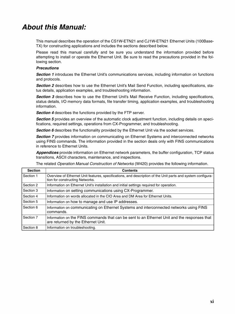
This manual describes the operation of the CS1W-ETN21 and CJ1W-ETN21 Ethernet Units (100Base-TX) for constructing applications and includes the sections described below.
Please read this manual carefully and be sure you understand the information provided beforeattempting to install or operate the Ethernet Unit. Be sure to read the precautions provided in the fol-lowing section.
Precautions
Section 1 introduces the Ethernet Unit’s communications services, including information on functionsand protocols.
Section 2 describes how to use the Ethernet Unit’s Mail Send Function, including specifications, sta-tus details, application examples, and troubleshooting information.
Section 3 describes how to use the Ethernet Unit’s Mail Receive Function, including specifications,status details, I/O memory data formats, file transfer timing, application examples, and troubleshootinginformation.
Section 4 describes the functions provided by the FTP server.
Section 5 provides an overview of the automatic clock adjustment function, including details on speci-fications, required settings, operations from CX-Programmer, and troubleshooting.
Section 6 describes the functionality provided by the Ethernet Unit via the socket services.
Section 7 provides information on communicating on Ethernet Systems and interconnected networksusing FINS commands. The information provided in the section deals only with FINS communicationsin reference to Ethernet Units.
Appendices provide information on Ethernet network parameters, the buffer configuration, TCP statustransitions, ASCII characters, maintenance, and inspections.
The related Operation Manual Construction of Networks (W420) provides the following information.
Section Contents
Section 1 Overview of Ethernet Unit features, specifications, and description of the Unit parts and system configura-tion for constructing Networks.
Section 2 Information on Ethernet Unit’s installation and initial settings required for operation.
Section 3 Information on setting communications using CX-Programmer. Section 4 Information on words allocated in the CIO Area and DM Area for Ethernet Units.
Section 5 Information on how to manage and use IP addresses.Section 6 Information on communicating on Ethernet Systems and interconnected networks using FINS
commands.Section 7 Information on the FINS commands that can be sent to an Ethernet Unit and the responses that
are returned by the Ethernet Unit.Section 8 Information on troubleshooting.
xi
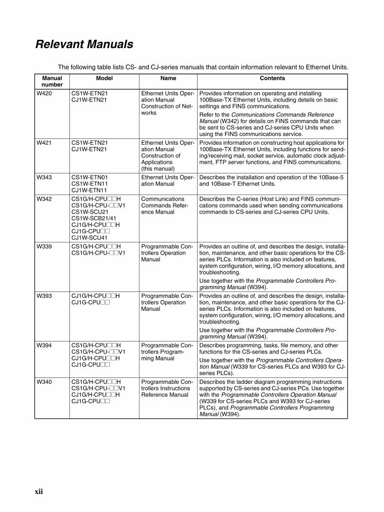
Relevant Manuals
The following table lists CS- and CJ-series manuals that contain information relevant to Ethernet Units.
Manual number
Model Name Contents
W420 CS1W-ETN21CJ1W-ETN21
Ethernet Units Oper-ation ManualConstruction of Net-works
Provides information on operating and installing 100Base-TX Ethernet Units, including details on basic settings and FINS communications.
Refer to the Communications Commands Reference Manual (W342) for details on FINS commands that can be sent to CS-series and CJ-series CPU Units when using the FINS communications service.
W421 CS1W-ETN21CJ1W-ETN21
Ethernet Units Oper-ation Manual Construction of Applications(this manual)
Provides information on constructing host applications for 100Base-TX Ethernet Units, including functions for send-ing/receiving mail, socket service, automatic clock adjust-ment, FTP server functions, and FINS communications.
W343 CS1W-ETN01CS1W-ETN11CJ1W-ETN11
Ethernet Units Oper-ation Manual
Describes the installation and operation of the 10Base-5 and 10Base-T Ethernet Units.
W342 CS1G/H-CPU@@HCS1G/H-CPU-@@V1CS1W-SCU21CS1W-SCB21/41CJ1G/H-CPU@@HCJ1G-CPU@@CJ1W-SCU41
Communications Commands Refer-ence Manual
Describes the C-series (Host Link) and FINS communi-cations commands used when sending communications commands to CS-series and CJ-series CPU Units.
W339 CS1G/H-CPU@@HCS1G/H-CPU-@@V1
Programmable Con-trollers Operation Manual
Provides an outline of, and describes the design, installa-tion, maintenance, and other basic operations for the CS-series PLCs. Information is also included on features, system configuration, wiring, I/O memory allocations, and troubleshooting.
Use together with the Programmable Controllers Pro-gramming Manual (W394).
W393 CJ1G/H-CPU@@HCJ1G-CPU@@
Programmable Con-trollers Operation Manual
Provides an outline of, and describes the design, installa-tion, maintenance, and other basic operations for the CJ-series PLCs. Information is also included on features, system configuration, wiring, I/O memory allocations, and troubleshooting. Use together with the Programmable Controllers Pro-gramming Manual (W394).
W394 CS1G/H-CPU@@HCS1G/H-CPU-@@V1CJ1G/H-CPU@@HCJ1G-CPU@@
Programmable Con-trollers Program-ming Manual
Describes programming, tasks, file memory, and other functions for the CS-series and CJ-series PLCs.
Use together with the Programmable Controllers Opera-tion Manual (W339 for CS-series PLCs and W393 for CJ-series PLCs).
W340 CS1G/H-CPU@@HCS1G/H-CPU-@@V1CJ1G/H-CPU@@HCJ1G-CPU@@
Programmable Con-trollers Instructions Reference Manual
Describes the ladder diagram programming instructions supported by CS-series and CJ-series PCs. Use together with the Programmable Controllers Operation Manual (W339 for CS-series PLCs and W393 for CJ-series PLCs), and Programmable Controllers Programming Manual (W394).
xii
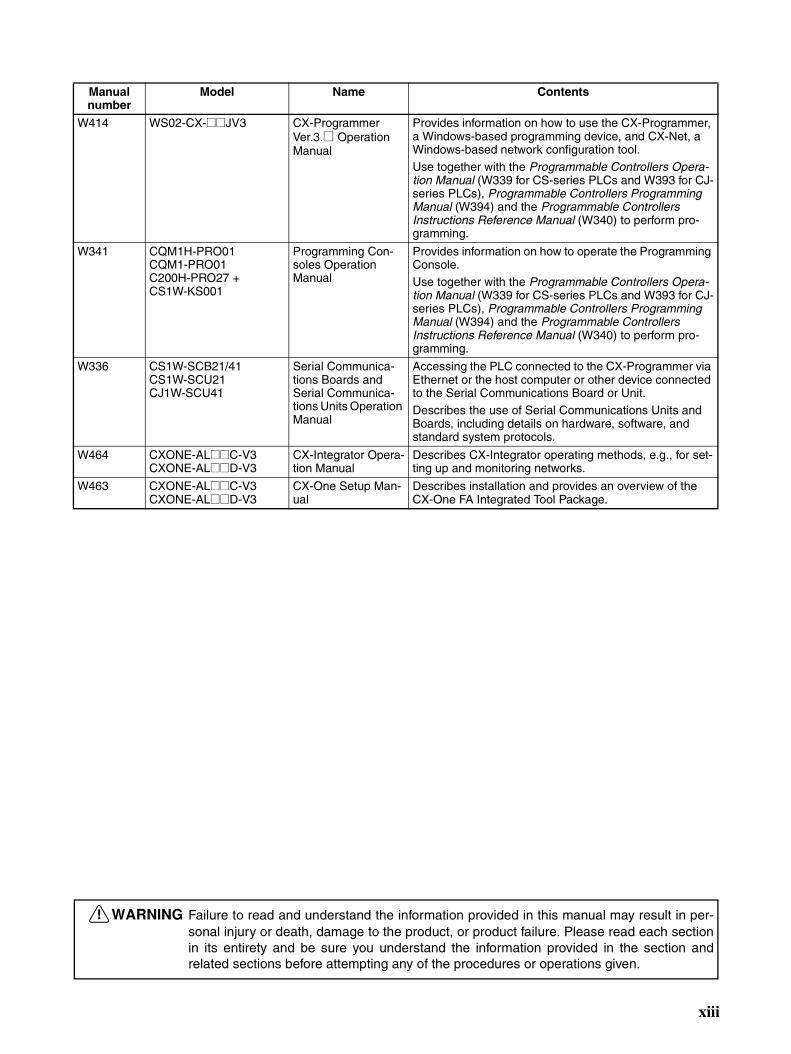
W414 WS02-CX-@@JV3 CX-Programmer Ver.3.@ Operation Manual
Provides information on how to use the CX-Programmer, a Windows-based programming device, and CX-Net, a Windows-based network configuration tool.Use together with the Programmable Controllers Opera-tion Manual (W339 for CS-series PLCs and W393 for CJ-series PLCs), Programmable Controllers Programming Manual (W394) and the Programmable Controllers Instructions Reference Manual (W340) to perform pro-gramming.
W341 CQM1H-PRO01CQM1-PRO01C200H-PRO27 + CS1W-KS001
Programming Con-soles Operation Manual
Provides information on how to operate the Programming Console.Use together with the Programmable Controllers Opera-tion Manual (W339 for CS-series PLCs and W393 for CJ-series PLCs), Programmable Controllers Programming Manual (W394) and the Programmable Controllers Instructions Reference Manual (W340) to perform pro-gramming.
W336 CS1W-SCB21/41CS1W-SCU21CJ1W-SCU41
Serial Communica-tions Boards and Serial Communica-tions Units Operation Manual
Accessing the PLC connected to the CX-Programmer via Ethernet or the host computer or other device connected to the Serial Communications Board or Unit. Describes the use of Serial Communications Units and Boards, including details on hardware, software, and standard system protocols.
W464 CXONE-AL@@C-V3CXONE-AL@@D-V3
CX-Integrator Opera-tion Manual
Describes CX-Integrator operating methods, e.g., for set-ting up and monitoring networks.
W463 CXONE-AL@@C-V3CXONE-AL@@D-V3
CX-One Setup Man-ual
Describes installation and provides an overview of the CX-One FA Integrated Tool Package.
Manual number
Model Name Contents
!WARNING Failure to read and understand the information provided in this manual may result in per-sonal injury or death, damage to the product, or product failure. Please read each sectionin its entirety and be sure you understand the information provided in the section andrelated sections before attempting any of the procedures or operations given.
xiii

xiv
Read and Understand this ManualPlease read and understand this manual before using the product. Please consult your OMRON representative if you have any questions or comments.
Warranty and Limitations of Liability
WARRANTY
OMRON's exclusive warranty is that the products are free from defects in materials and workmanship for a period of one year (or other period if specified) from date of sale by OMRON.
OMRON MAKES NO WARRANTY OR REPRESENTATION, EXPRESS OR IMPLIED, REGARDING NON-INFRINGEMENT, MERCHANTABILITY, OR FITNESS FOR PARTICULAR PURPOSE OF THE PRODUCTS. ANY BUYER OR USER ACKNOWLEDGES THAT THE BUYER OR USER ALONE HAS DETERMINED THAT THE PRODUCTS WILL SUITABLY MEET THE REQUIREMENTS OF THEIR INTENDED USE. OMRON DISCLAIMS ALL OTHER WARRANTIES, EXPRESS OR IMPLIED.
LIMITATIONS OF LIABILITY
OMRON SHALL NOT BE RESPONSIBLE FOR SPECIAL, INDIRECT, OR CONSEQUENTIAL DAMAGES, LOSS OF PROFITS OR COMMERCIAL LOSS IN ANY WAY CONNECTED WITH THE PRODUCTS, WHETHER SUCH CLAIM IS BASED ON CONTRACT, WARRANTY, NEGLIGENCE, OR STRICT LIABILITY.
In no event shall the responsibility of OMRON for any act exceed the individual price of the product on which liability is asserted.
IN NO EVENT SHALL OMRON BE RESPONSIBLE FOR WARRANTY, REPAIR, OR OTHER CLAIMS REGARDING THE PRODUCTS UNLESS OMRON'S ANALYSIS CONFIRMS THAT THE PRODUCTS WERE PROPERLY HANDLED, STORED, INSTALLED, AND MAINTAINED AND NOT SUBJECT TO CONTAMINATION, ABUSE, MISUSE, OR INAPPROPRIATE MODIFICATION OR REPAIR.
xv

Application Considerations
SUITABILITY FOR USE
OMRON shall not be responsible for conformity with any standards, codes, or regulations that apply to the combination of products in the customer's application or use of the products.
At the customer's request, OMRON will provide applicable third party certification documents identifying ratings and limitations of use that apply to the products. This information by itself is not sufficient for a complete determination of the suitability of the products in combination with the end product, machine, system, or other application or use.
The following are some examples of applications for which particular attention must be given. This is not intended to be an exhaustive list of all possible uses of the products, nor is it intended to imply that the uses listed may be suitable for the products:
• Outdoor use, uses involving potential chemical contamination or electrical interference, or conditions or uses not described in this manual.
• Nuclear energy control systems, combustion systems, railroad systems, aviation systems, medical equipment, amusement machines, vehicles, safety equipment, and installations subject to separate industry or government regulations.
• Systems, machines, and equipment that could present a risk to life or property.
Please know and observe all prohibitions of use applicable to the products.
NEVER USE THE PRODUCTS FOR AN APPLICATION INVOLVING SERIOUS RISK TO LIFE OR PROPERTY WITHOUT ENSURING THAT THE SYSTEM AS A WHOLE HAS BEEN DESIGNED TO ADDRESS THE RISKS, AND THAT THE OMRON PRODUCTS ARE PROPERLY RATED AND INSTALLED FOR THE INTENDED USE WITHIN THE OVERALL EQUIPMENT OR SYSTEM.
PROGRAMMABLE PRODUCTS
OMRON shall not be responsible for the user's programming of a programmable product, or any consequence thereof.
xvi
Disclaimers
CHANGE IN SPECIFICATIONS
Product specifications and accessories may be changed at any time based on improvements and other reasons.
It is our practice to change model numbers when published ratings or features are changed, or when significant construction changes are made. However, some specifications of the products may be changed without any notice. When in doubt, special model numbers may be assigned to fix or establish key specifications for your application on your request. Please consult with your OMRON representative at any time to confirm actual specifications of purchased products.
DIMENSIONS AND WEIGHTS
Dimensions and weights are nominal and are not to be used for manufacturing purposes, even when tolerances are shown.
PERFORMANCE DATA
Performance data given in this manual is provided as a guide for the user in determining suitability and does not constitute a warranty. It may represent the result of OMRON's test conditions, and the users must correlate it to actual application requirements. Actual performance is subject to the OMRON Warranty and Limitations of Liability.
ERRORS AND OMISSIONS
The information in this manual has been carefully checked and is believed to be accurate; however, no responsibility is assumed for clerical, typographical, or proofreading errors, or omissions.
xvii

xviii
Unit Versions of CS/CJ-series
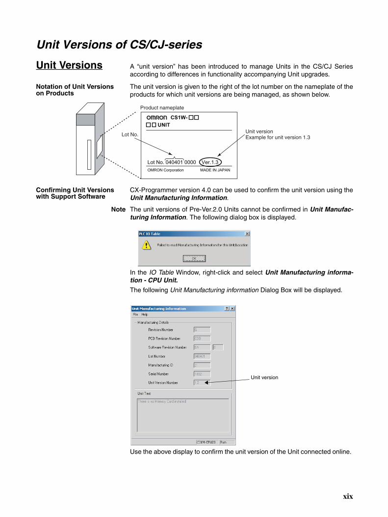
Unit Versions A “unit version” has been introduced to manage Units in the CS/CJ Seriesaccording to differences in functionality accompanying Unit upgrades.
Notation of Unit Versions on Products
The unit version is given to the right of the lot number on the nameplate of theproducts for which unit versions are being managed, as shown below.
Confirming Unit Versions with Support Software
CX-Programmer version 4.0 can be used to confirm the unit version using theUnit Manufacturing Information.
Note The unit versions of Pre-Ver.2.0 Units cannot be confirmed in Unit Manufac-turing Information. The following dialog box is displayed.
In the IO Table Window, right-click and select Unit Manufacturing informa-tion - CPU Unit.
The following Unit Manufacturing information Dialog Box will be displayed.
Use the above display to confirm the unit version of the Unit connected online.
CS1W-
UNIT
Lot No. 040401 0000 Ver.1.3
OMRON Corporation MADE IN JAPAN
Product nameplate
Unit versionExample for unit version 1.3Lot No.
Unit version
xix
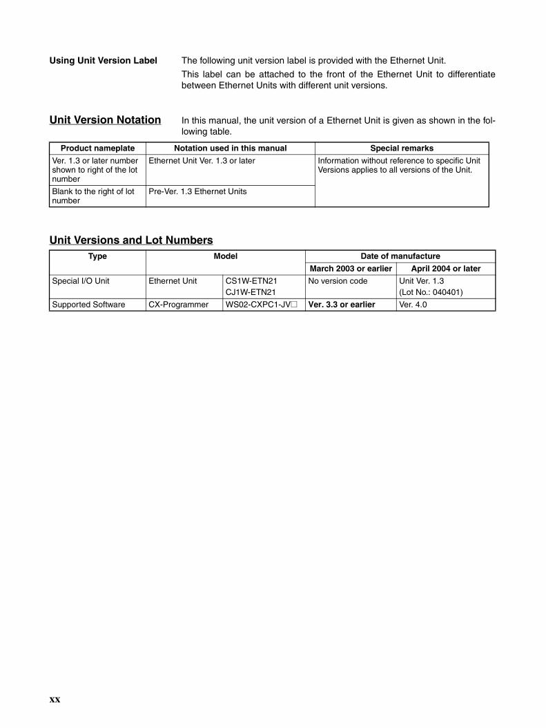
Using Unit Version Label The following unit version label is provided with the Ethernet Unit.
This label can be attached to the front of the Ethernet Unit to differentiatebetween Ethernet Units with different unit versions.
Unit Version Notation In this manual, the unit version of a Ethernet Unit is given as shown in the fol-lowing table.
Unit Versions and Lot Numbers
Product nameplate Notation used in this manual Special remarks
Ver. 1.3 or later number shown to right of the lot number
Ethernet Unit Ver. 1.3 or later Information without reference to specific Unit Versions applies to all versions of the Unit.
Blank to the right of lot number
Pre-Ver. 1.3 Ethernet Units
Type Model Date of manufacture
March 2003 or earlier April 2004 or later
Special I/O Unit Ethernet Unit CS1W-ETN21CJ1W-ETN21
No version code Unit Ver. 1.3(Lot No.: 040401)
Supported Software CX-Programmer WS02-CXPC1-JV@ Ver. 3.3 or earlier Ver. 4.0
xx
PRECAUTIONS
This section provides general precautions for using the CS1W-ETN21 and CJ1W-ETN21 Ethernet Units (100Base-TX).
The information contained in this section is important for the safe and reliable application of Ethernet Units. Youmust read this section and understand the information contained before attempting to set up or operate an EthernetUnit.
1 Intended Audience . . . . . . . . . . . . . . . . . . . . . . . . . . . . . . . . . . . . . . . . . . . . . xxii2 General Precautions . . . . . . . . . . . . . . . . . . . . . . . . . . . . . . . . . . . . . . . . . . . . xxii3 Safety Precautions. . . . . . . . . . . . . . . . . . . . . . . . . . . . . . . . . . . . . . . . . . . . . . xxii4 Operating Environment Precautions . . . . . . . . . . . . . . . . . . . . . . . . . . . . . . . . xxiv5 Application Precautions . . . . . . . . . . . . . . . . . . . . . . . . . . . . . . . . . . . . . . . . . xxiv6 Conformance to EC Directives . . . . . . . . . . . . . . . . . . . . . . . . . . . . . . . . . . . . xxvi
6-1 Applicable Directives . . . . . . . . . . . . . . . . . . . . . . . . . . . . . . . . . . . . xxvi6-2 Concepts . . . . . . . . . . . . . . . . . . . . . . . . . . . . . . . . . . . . . . . . . . . . . . xxvi
xxi
Intended Audience 1
1 Intended AudienceThis manual is intended for the following personnel, who must also haveknowledge of electrical systems (an electrical engineer or the equivalent).
• Personnel in charge of installing FA systems.
• Personnel in charge of designing FA systems.
• Personnel in charge of managing FA systems and facilities.
2 General PrecautionsThe user must operate the product according to the performance specifica-tions described in the operation manuals.
Before using the product under conditions which are not described in themanual or applying the product to nuclear control systems, railroad systems,aviation systems, vehicles, combustion systems, medical equipment, amuse-ment machines, safety equipment, and other systems, machines, and equip-ment that may have a serious influence on lives and property if usedimproperly, consult your OMRON representative.
Make sure that the ratings and performance characteristics of the product aresufficient for the systems, machines, and equipment, and be sure to providethe systems, machines, and equipment with double safety mechanisms.
This manual provides information for programming and operating the Unit. Besure to read this manual before attempting to use the Unit and keep this man-ual close at hand for reference during operation.
!WARNING It is extremely important that a PLC and all PLC Units be used for the speci-fied purpose and under the specified conditions, especially in applications thatcan directly or indirectly affect human life. You must consult with yourOMRON representative before applying a PLC System to the above-men-tioned applications.
3 Safety Precautions
!WARNING Do not attempt to take any Unit apart while the power is being supplied. Doingso may result in electric shock.
!WARNING Do not touch any of the terminals or terminal blocks while the power is beingsupplied. Doing so may result in electric shock.
!WARNING Do not attempt to disassemble, repair, or modify any Units. Any attempt to doso may result in malfunction, fire, or electric shock.
xxii
Safety Precautions 3
!WARNING Provide safety measures in external circuits (i.e., not in the ProgrammableController), including the following items, to ensure safety in the system if anabnormality occurs due to malfunction of the PLC or another external factoraffecting the PLC operation. Not doing so may result in serious accidents.
• Emergency stop circuits, interlock circuits, limit circuits, and similar safetymeasures must be provided in external control circuits.
• The PLC will turn OFF all outputs when its self-diagnosis function detectsany error or when a severe failure alarm (FALS) instruction is executed.As a countermeasure for such errors, external safety measures must beprovided to ensure safety in the system.
• The PLC outputs may remain ON or OFF due to deposits on or burning ofthe output relays, or destruction of the output transistors. As a counter-measure for such problems, external safety measures must be providedto ensure safety in the system.
• When the 24-V DC output (service power supply to the PLC) is over-loaded or short-circuited, the voltage may drop and result in the outputsbeing turned OFF. As a countermeasure for such problems, externalsafety measures must be provided to ensure safety in the system.
!Caution Execute online editing only after confirming that no adverse effects will becaused by extending the cycle time. Otherwise, the input signals may not bereadable.
• Emergency stop circuits, interlock circuits, limit circuits, and similar safetymeasures must be provided in external control circuits.
!Caution Fail-safe measures must be taken by the customer to ensure safety in theevent of incorrect, missing, or abnormal signals caused by broken signal lines,momentary power interruptions, or other causes. Serious accidents mayresult from abnormal operation if proper measures are not provided.
!Caution Confirm safety at the destination node before changing or transferring toanother node the contents of a program, the PLC Setup, I/O tables, or I/Omemory. Changing or transferring any of these without confirming safety mayresult in injury.
!Caution Tighten the screws on the terminal block of the AC Power Supply Unit to thetorque specified in the operation manual. The loose screws may result inburning or malfunction.
xxiii
Operating Environment Precautions 4
4 Operating Environment Precautions
!Caution Do not operate the control system in the following locations:
• Locations subject to direct sunlight.
• Locations subject to temperatures or humidity outside the range specifiedin the specifications.
• Locations subject to condensation as the result of severe changes in tem-perature.
• Locations subject to corrosive or flammable gases.
• Locations subject to dust (especially iron dust) or salts.
• Locations subject to exposure to water, oil, or chemicals.
• Locations subject to shock or vibration.
!Caution Take appropriate and sufficient countermeasures when installing systems inthe following locations:
• Locations subject to static electricity or other forms of noise.
• Locations subject to strong electromagnetic fields.
• Locations subject to possible exposure to radioactivity.
• Locations close to power supplies.
5 Application PrecautionsObserve the following precautions when using the Ethernet Unit.
!WARNING Always heed these precautions. Failure to abide by the following precautionscould lead to serious or possibly fatal injury.
• Always connect to a ground of 100 Ω or less when installing the Units. Notconnecting to a ground of 100 Ω or less may result in electric shock.
• Always turn OFF the power supply to the CPU Unit and Slaves beforeattempting any of the following. Not turning OFF the power supply mayresult in malfunction or electric shock.
• Mounting or dismounting I/O Units, CPU Units, Memory Packs, orMaster Units.
• Assembling the Units.
• Setting DIP switches or rotary switches.
• Connecting cables or wiring the system.
• Connecting or disconnecting the connectors.
!Caution Failure to abide by the following precautions could lead to faulty operation ofthe Ethernet Unit or the system, or could damage the Ethernet Unit. Alwaysheed these precautions.
• Interlock circuits, limit circuits, and similar safety measures in external cir-cuits (i.e., not in the Programmable Controller) must be provided by thecustomer.
xxiv
Application Precautions 5
• Always use the power supply voltages specified in the operation manuals.An incorrect voltage may result in malfunction or burning.
• Take appropriate measures to ensure that the specified power with therated voltage and frequency is supplied. Be particularly careful in placeswhere the power supply is unstable. An incorrect power supply may resultin malfunction.
• Install external breakers and take other safety measures against short-cir-cuiting in external wiring. Insufficient safety measures
• Make sure that all the Backplane mounting screws, terminal block screws,and cable connector screws are tightened to the torque specified in therelevant manuals. Incorrect tightening torque may result in malfunction.
• Leave the label attached to the Unit when wiring. Removing the label mayresult in malfunction if foreign matter enters the Unit.
• Remove the label after the completion of wiring to ensure proper heat dis-sipation. Leaving the label attached may result in malfunction.
• Use crimp terminals for wiring. Do not connect bare stranded wiresdirectly to terminals. Connection of bare stranded wires may result inburning.
• Observe the following precautions when wiring the communicationscable.
• Separate the communications cables from the power lines or high-volt-age lines.
• Do not bend the communications cables past their natural bending ra-dius.
• Do not pull on the communications cables.
• Do not place heavy objects on top of the communications cables.
• Always lay communications cable inside ducts.
• Use appropriate communications cables.
• Make sure that the terminal blocks, expansion cable connectors, andother items with locking devices are locked in place.
• Wire all connections correctly according to instructions in this manual.
• Double-check all wiring and switch settings before turning ON the powersupply. Incorrect wiring may result in burning.
• Mount Units only after checking terminal blocks and connectors com-pletely.
• Check the user program for proper execution before actually running it onthe Unit. Not checking the program may result in unexpected operation.
• Confirm that no adverse effect will occur in the system before attemptingany of the following. Not doing so may result in an unexpected operation.
• Changing the operating mode of the PLC.
• Force-setting/force-resetting any bit in memory.
• Changing the present value of any word or any set value in memory.
• After replacing Units, resume operation only after transferring to the newCPU Unit and/or Special I/O Units the contents of the DM Area, HR Area,programs, parameters, and other data required for resuming operation.Not doing so may result in an unexpected operation.
• Before touching a Unit, be sure to first touch a grounded metallic object inorder to discharge any static build-up. Not doing so may result in malfunc-tion or damage.
xxv
Conformance to EC Directives 6
• When transporting the Unit, use special packing boxes and protect it frombeing exposed to excessive vibration or impacts during transportation.
• CPU Bus Units will be restarted when routing tables are transferred froma Programming Device to the CPU Unit. Restarting these Units is requiredto read and enable the new routing tables. Confirm that the system willnot be adversely affected before allowing the CPU Bus Units to be reset.
6 Conformance to EC Directives
6-1 Applicable Directives• EMC Directives
• Low Voltage Directive
6-2 ConceptsEMC DirectivesOMRON devices that comply with EC Directives also conform to the relatedEMC standards so that they can be more easily built into other devices or theoverall machine. The actual products have been checked for conformity toEMC standards (see the following note). Whether the products conform to thestandards in the system used by the customer, however, must be checked bythe customer.
EMC-related performance of the OMRON devices that comply with EC Direc-tives will vary depending on the configuration, wiring, and other conditions ofthe equipment or control panel on which the OMRON devices are installed.The customer must, therefore, perform the final check to confirm that devicesand the overall machine conform to EMC standards.
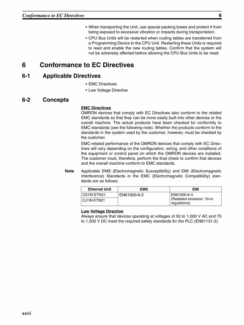
Note Applicable EMS (Electromagnetic Susceptibility) and EMI (ElectromagneticInterference) Standards in the EMC (Electromagnetic Compatibility) stan-dards are as follows:
Low Voltage DirectiveAlways ensure that devices operating at voltages of 50 to 1,000 V AC and 75to 1,500 V DC meet the required safety standards for the PLC (EN61131-2).
Ethernet Unit EMS EMI
CS1W-ETN21 EN61000-6-2 EN61000-6-4 (Radiated emission: 10-m regulations)
CJ1W-ETN21
xxvi
SECTION 1Introduction
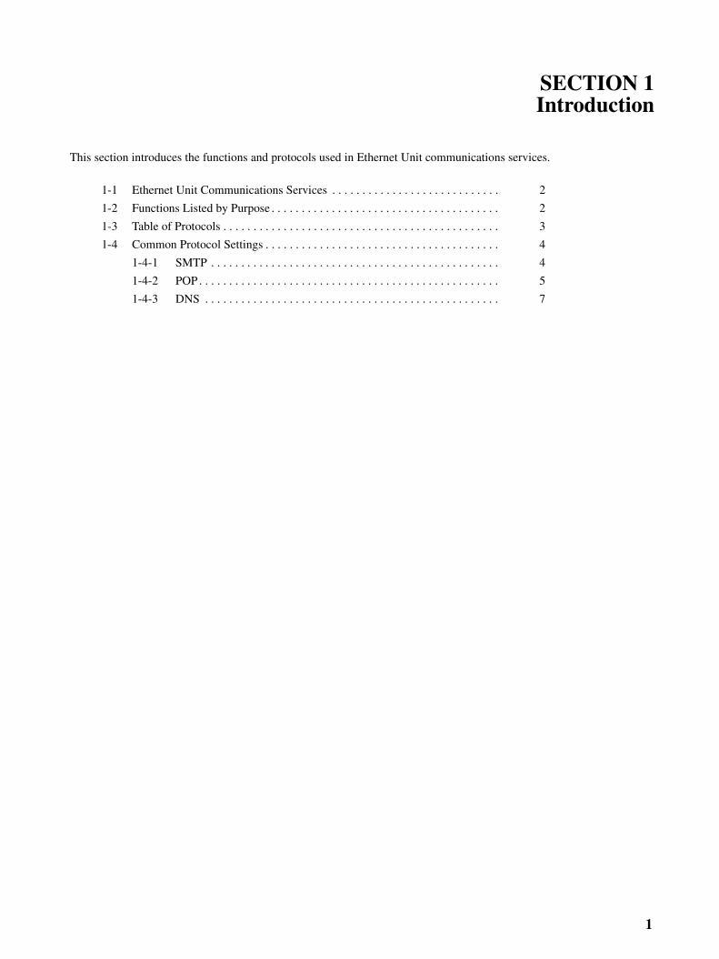
This section introduces the functions and protocols used in Ethernet Unit communications services.
1-1 Ethernet Unit Communications Services . . . . . . . . . . . . . . . . . . . . . . . . . . . . 2
1-2 Functions Listed by Purpose . . . . . . . . . . . . . . . . . . . . . . . . . . . . . . . . . . . . . . 2
1-3 Table of Protocols . . . . . . . . . . . . . . . . . . . . . . . . . . . . . . . . . . . . . . . . . . . . . . 3
1-4 Common Protocol Settings . . . . . . . . . . . . . . . . . . . . . . . . . . . . . . . . . . . . . . . 4
1-4-1 SMTP . . . . . . . . . . . . . . . . . . . . . . . . . . . . . . . . . . . . . . . . . . . . . . . . 4
1-4-2 POP. . . . . . . . . . . . . . . . . . . . . . . . . . . . . . . . . . . . . . . . . . . . . . . . . . 5
1-4-3 DNS . . . . . . . . . . . . . . . . . . . . . . . . . . . . . . . . . . . . . . . . . . . . . . . . . 7
1
Ethernet Unit Communications Services Section 1-1
1-1 Ethernet Unit Communications Services
Note When transferring data through the internet, a global IP address must beacquired for the Ethernet Unit.
1-2 Functions Listed by Purpose
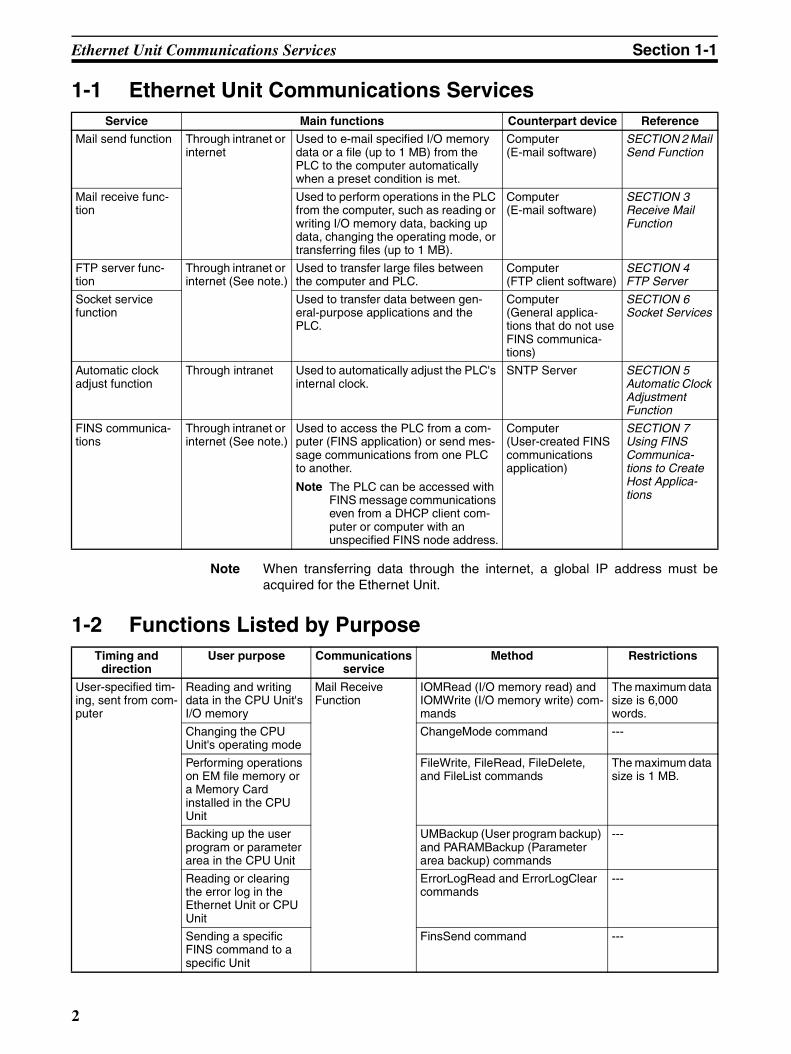
Service Main functions Counterpart device Reference
Mail send function Through intranet or internet
Used to e-mail specified I/O memory data or a file (up to 1 MB) from the PLC to the computer automatically when a preset condition is met.
Computer(E-mail software)
SECTION 2 Mail Send Function
Mail receive func-tion
Used to perform operations in the PLC from the computer, such as reading or writing I/O memory data, backing up data, changing the operating mode, or transferring files (up to 1 MB).
Computer(E-mail software)
SECTION 3 Receive Mail Function
FTP server func-tion
Through intranet or internet (See note.)
Used to transfer large files between the computer and PLC.
Computer(FTP client software)
SECTION 4 FTP Server
Socket service function
Used to transfer data between gen-eral-purpose applications and the PLC.
Computer(General applica-tions that do not use FINS communica-tions)
SECTION 6 Socket Services
Automatic clock adjust function
Through intranet Used to automatically adjust the PLC's internal clock.
SNTP Server SECTION 5 Automatic Clock Adjustment Function
FINS communica-tions
Through intranet or internet (See note.)
Used to access the PLC from a com-puter (FINS application) or send mes-sage communications from one PLC to another.
Note The PLC can be accessed with FINS message communications even from a DHCP client com-puter or computer with an unspecified FINS node address.
Computer(User-created FINS communications application)
SECTION 7 Using FINS Communica-tions to Create Host Applica-tions
Timing and direction
User purpose Communications service
Method Restrictions
User-specified tim-ing, sent from com-puter
Reading and writing data in the CPU Unit's I/O memory
Mail Receive Function
IOMRead (I/O memory read) and IOMWrite (I/O memory write) com-mands
The maximum data size is 6,000 words.
Changing the CPU Unit's operating mode
ChangeMode command ---
Performing operations on EM file memory or a Memory Card installed in the CPU Unit
FileWrite, FileRead, FileDelete, and FileList commands
The maximum data size is 1 MB.
Backing up the user program or parameter area in the CPU Unit
UMBackup (User program backup) and PARAMBackup (Parameter area backup) commands
---
Reading or clearing the error log in the Ethernet Unit or CPU Unit
ErrorLogRead and ErrorLogClear commands
---
Sending a specific FINS command to a specific Unit
FinsSend command ---
2
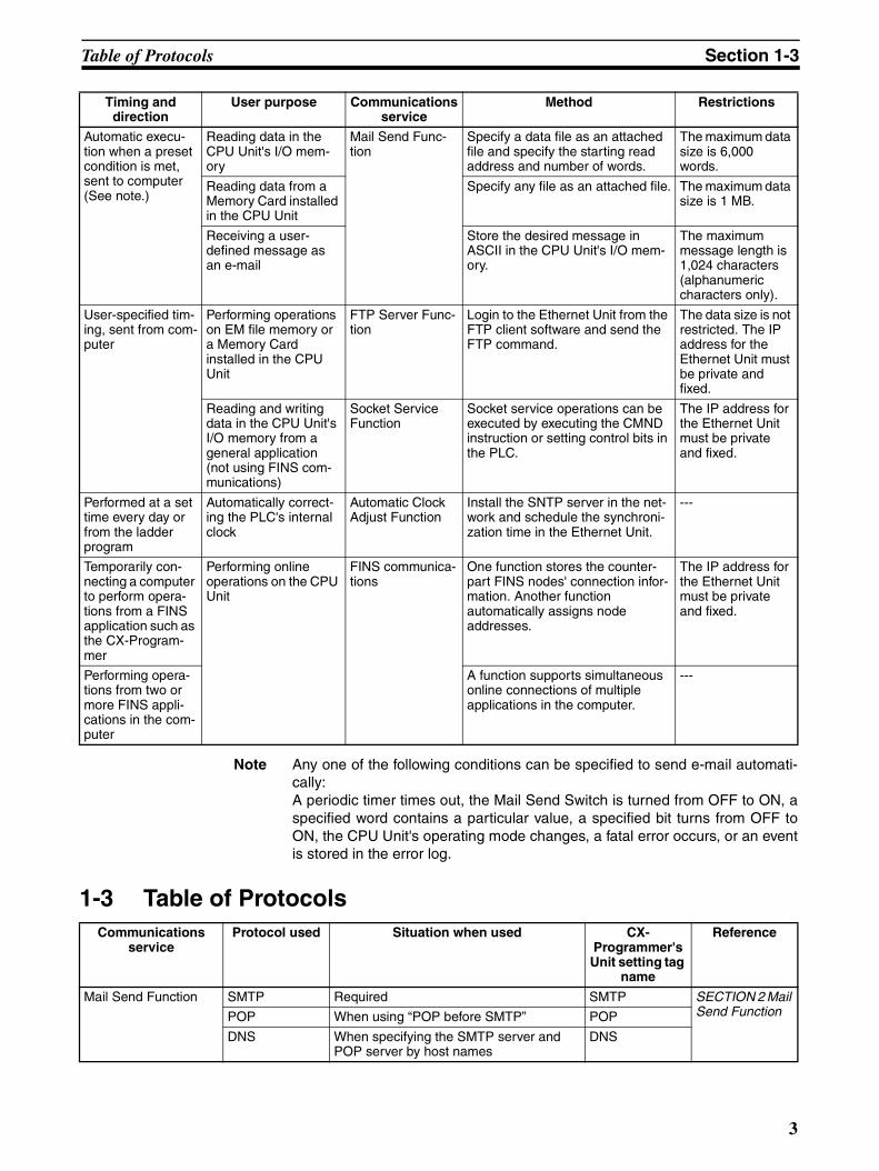
Table of Protocols Section 1-3
Note Any one of the following conditions can be specified to send e-mail automati-cally:A periodic timer times out, the Mail Send Switch is turned from OFF to ON, aspecified word contains a particular value, a specified bit turns from OFF toON, the CPU Unit's operating mode changes, a fatal error occurs, or an eventis stored in the error log.
1-3 Table of Protocols
Automatic execu-tion when a preset condition is met, sent to computer (See note.)
Reading data in the CPU Unit's I/O mem-ory
Mail Send Func-tion
Specify a data file as an attached file and specify the starting read address and number of words.
The maximum data size is 6,000 words.
Reading data from a Memory Card installed in the CPU Unit
Specify any file as an attached file. The maximum data size is 1 MB.
Receiving a user-defined message as an e-mail
Store the desired message in ASCII in the CPU Unit's I/O mem-ory.
The maximum message length is 1,024 characters (alphanumeric characters only).
User-specified tim-ing, sent from com-puter
Performing operations on EM file memory or a Memory Card installed in the CPU Unit
FTP Server Func-tion
Login to the Ethernet Unit from the FTP client software and send the FTP command.
The data size is not restricted. The IP address for the Ethernet Unit must be private and fixed.
Reading and writing data in the CPU Unit's I/O memory from a general application (not using FINS com-munications)
Socket Service Function
Socket service operations can be executed by executing the CMND instruction or setting control bits in the PLC.
The IP address for the Ethernet Unit must be private and fixed.
Performed at a set time every day or from the ladder program
Automatically correct-ing the PLC's internal clock
Automatic Clock Adjust Function
Install the SNTP server in the net-work and schedule the synchroni-zation time in the Ethernet Unit.
---
Temporarily con-necting a computer to perform opera-tions from a FINS application such as the CX-Program-mer
Performing online operations on the CPU Unit
FINS communica-tions
One function stores the counter-part FINS nodes' connection infor-mation. Another function automatically assigns node addresses.
The IP address for the Ethernet Unit must be private and fixed.
Performing opera-tions from two or more FINS appli-cations in the com-puter
A function supports simultaneous online connections of multiple applications in the computer.
---
Communications service
Protocol used Situation when used CX-Programmer's Unit setting tag
name
Reference
Mail Send Function SMTP Required SMTP SECTION 2 Mail Send FunctionPOP When using “POP before SMTP” POP
DNS When specifying the SMTP server and POP server by host names
DNS
Timing and direction
User purpose Communications service
Method Restrictions
3
Common Protocol Settings Section 1-4
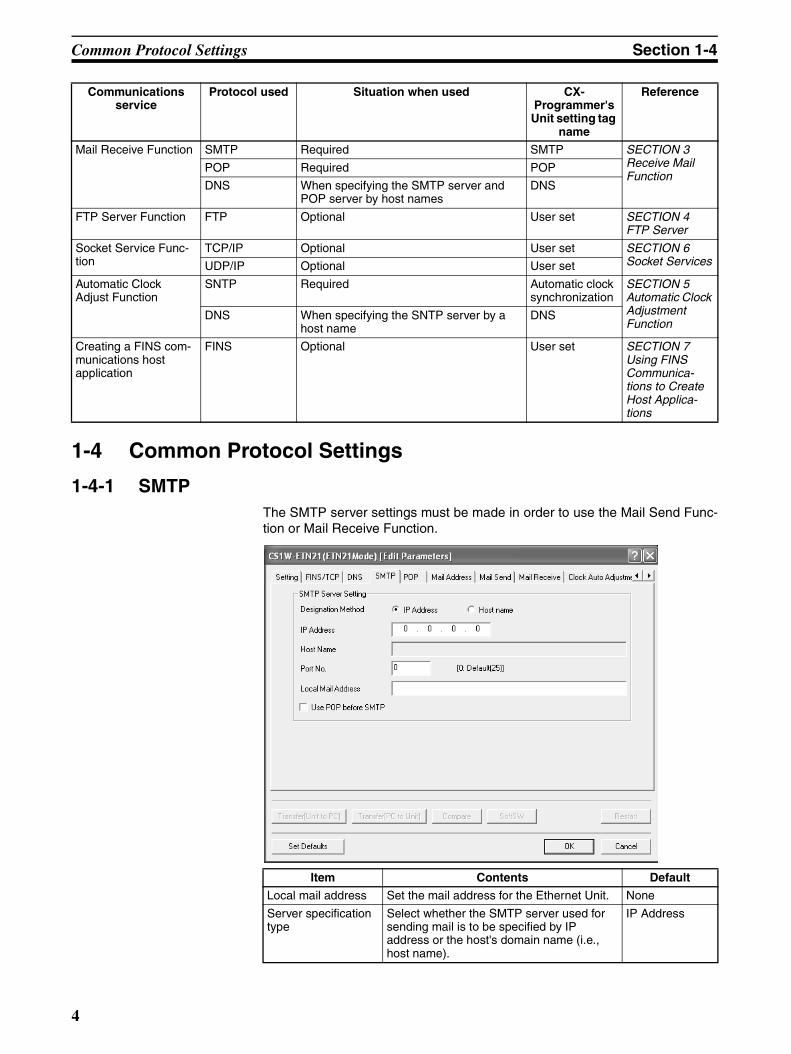
1-4 Common Protocol Settings
1-4-1 SMTPThe SMTP server settings must be made in order to use the Mail Send Func-tion or Mail Receive Function.
Mail Receive Function SMTP Required SMTP SECTION 3 Receive Mail Function
POP Required POP
DNS When specifying the SMTP server and POP server by host names
DNS
FTP Server Function FTP Optional User set SECTION 4 FTP Server
Socket Service Func-tion
TCP/IP Optional User set SECTION 6 Socket ServicesUDP/IP Optional User set
Automatic Clock Adjust Function
SNTP Required Automatic clock synchronization
SECTION 5 Automatic Clock Adjustment Function
DNS When specifying the SNTP server by a host name
DNS
Creating a FINS com-munications host application
FINS Optional User set SECTION 7 Using FINS Communica-tions to Create Host Applica-tions
Communications service
Protocol used Situation when used CX-Programmer's Unit setting tag
name
Reference
Item Contents Default
Local mail address Set the mail address for the Ethernet Unit. None
Server specification type
Select whether the SMTP server used for sending mail is to be specified by IP address or the host's domain name (i.e., host name).
IP Address
4
Common Protocol Settings Section 1-4
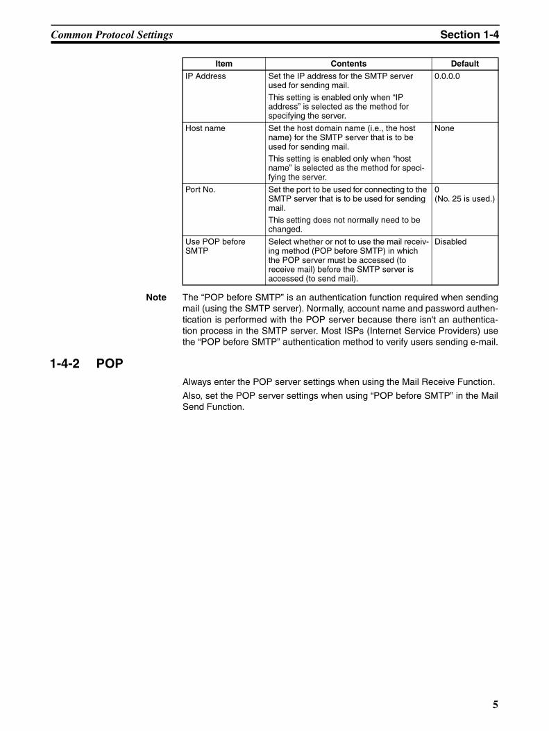
Note The “POP before SMTP” is an authentication function required when sendingmail (using the SMTP server). Normally, account name and password authen-tication is performed with the POP server because there isn't an authentica-tion process in the SMTP server. Most ISPs (Internet Service Providers) usethe “POP before SMTP” authentication method to verify users sending e-mail.
1-4-2 POPAlways enter the POP server settings when using the Mail Receive Function.
Also, set the POP server settings when using “POP before SMTP” in the MailSend Function.
IP Address Set the IP address for the SMTP server used for sending mail.
This setting is enabled only when “IP address” is selected as the method for specifying the server.
0.0.0.0
Host name Set the host domain name (i.e., the host name) for the SMTP server that is to be used for sending mail.This setting is enabled only when “host name” is selected as the method for speci-fying the server.
None
Port No. Set the port to be used for connecting to the SMTP server that is to be used for sending mail.This setting does not normally need to be changed.
0(No. 25 is used.)
Use POP before SMTP
Select whether or not to use the mail receiv-ing method (POP before SMTP) in which the POP server must be accessed (to receive mail) before the SMTP server is accessed (to send mail).
Disabled
Item Contents Default
5
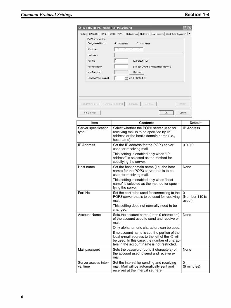
Common Protocol Settings Section 1-4
Item Contents Default
Server specification type
Select whether the POP3 server used for receiving mail is to be specified by IP address or the host's domain name (i.e., host name).
IP Address
IP Address Set the IP address for the POP3 server used for receiving mail.
This setting is enabled only when “IP address” is selected as the method for specifying the server.
0.0.0.0
Host name Set the host domain name (i.e., the host name) for the POP3 server that is to be used for receiving mail.This setting is enabled only when “host name” is selected as the method for speci-fying the server.
None
Port No. Set the port to be used for connecting to the POP3 server that is to be used for receiving mail.This setting does not normally need to be changed.
0(Number 110 is used.)
Account Name Sets the account name (up to 9 characters) of the account used to send and receive e-mail.Only alphanumeric characters can be used.If no account name is set, the portion of the local e-mail address to the left of the @ will be used. In this case, the number of charac-ters in the account name is not restricted.
None
Mail password Sets the password (up to 8 characters) of the account used to send and receive e-mail.
None
Server access inter-val time
Set the interval for sending and receiving mail. Mail will be automatically sent and received at the interval set here.
0(5 minutes)
6
Common Protocol Settings Section 1-4
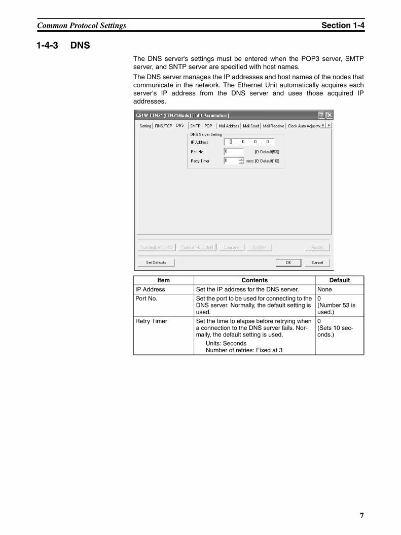
1-4-3 DNSThe DNS server's settings must be entered when the POP3 server, SMTPserver, and SNTP server are specified with host names.
The DNS server manages the IP addresses and host names of the nodes thatcommunicate in the network. The Ethernet Unit automatically acquires eachserver's IP address from the DNS server and uses those acquired IPaddresses.
Item Contents Default
IP Address Set the IP address for the DNS server. None
Port No. Set the port to be used for connecting to the DNS server. Normally, the default setting is used.
0(Number 53 is used.)
Retry Timer Set the time to elapse before retrying when a connection to the DNS server fails. Nor-mally, the default setting is used.
Units: SecondsNumber of retries: Fixed at 3
0 (Sets 10 sec-onds.)
7

Common Protocol Settings Section 1-4
8
SECTION 2Mail Send Function
This section provides an overview and describes how to use the Ethernet Unit’s Mail Send Function, including applicationexamples and troubleshooting information.
2-1 Mail Send Function Overview . . . . . . . . . . . . . . . . . . . . . . . . . . . . . . . . . . . . 10
2-1-1 Introduction. . . . . . . . . . . . . . . . . . . . . . . . . . . . . . . . . . . . . . . . . . . . 10
2-1-2 Comparison with the Earlier Mail Send Function . . . . . . . . . . . . . . 11
2-1-3 Mail Send Function's Compatibility with Earlier Models . . . . . . . . 11
2-2 Mail Send Function Details. . . . . . . . . . . . . . . . . . . . . . . . . . . . . . . . . . . . . . . 11
2-2-1 Contents of E-mail Body . . . . . . . . . . . . . . . . . . . . . . . . . . . . . . . . . 12
2-2-2 Contents of E-mail Body . . . . . . . . . . . . . . . . . . . . . . . . . . . . . . . . . 13
2-2-3 Attached File Details . . . . . . . . . . . . . . . . . . . . . . . . . . . . . . . . . . . . 15
2-2-4 Summary of E-mail Body Information and Attached Files . . . . . . . 16
2-3 Mail Send Function Specifications . . . . . . . . . . . . . . . . . . . . . . . . . . . . . . . . . 17
2-3-1 Function Specifications . . . . . . . . . . . . . . . . . . . . . . . . . . . . . . . . . . 17
2-3-2 Details of the Available Mail Triggers . . . . . . . . . . . . . . . . . . . . . . . 18
2-4 Using the Mail Send Function . . . . . . . . . . . . . . . . . . . . . . . . . . . . . . . . . . . . 18
2-4-1 Procedure . . . . . . . . . . . . . . . . . . . . . . . . . . . . . . . . . . . . . . . . . . . . . 18
2-4-2 Settings Required for the Mail Send Function . . . . . . . . . . . . . . . . . 19
2-4-3 Mail Address. . . . . . . . . . . . . . . . . . . . . . . . . . . . . . . . . . . . . . . . . . . 21
2-4-4 Send Mail . . . . . . . . . . . . . . . . . . . . . . . . . . . . . . . . . . . . . . . . . . . . . 21
2-5 Mail Send Function Status . . . . . . . . . . . . . . . . . . . . . . . . . . . . . . . . . . . . . . . 25
2-5-1 Send Mail Status . . . . . . . . . . . . . . . . . . . . . . . . . . . . . . . . . . . . . . . . 25
2-5-2 Mail Send Switch, Accessing Memory/Sending Mail Flag . . . . . . . 26
2-6 I/O Memory Data Formats . . . . . . . . . . . . . . . . . . . . . . . . . . . . . . . . . . . . . . . 26
2-7 Attached File Transfer Times . . . . . . . . . . . . . . . . . . . . . . . . . . . . . . . . . . . . . 28
2-8 Mail Send Function Errors . . . . . . . . . . . . . . . . . . . . . . . . . . . . . . . . . . . . . . . 28
2-8-1 Identifying and Correcting Mail Send Function Errors . . . . . . . . . . 28
2-8-2 Troubleshooting Mail Send Errors with LED Indicators . . . . . . . . . 29
2-8-3 Error Log Error Codes for the Mail Send Function . . . . . . . . . . . . . 29
2-9 Example Application. . . . . . . . . . . . . . . . . . . . . . . . . . . . . . . . . . . . . . . . . . . . 30
2-9-1 Step 1. Create the I/O Table . . . . . . . . . . . . . . . . . . . . . . . . . . . . . . . 30
2-9-2 Step 2. Make the Unit Setup Settings from the CX-Programmer. . . 30
2-9-3 Step 3. Transfer the CPU Bus Unit Setup Settings. . . . . . . . . . . . . . 32
2-9-4 Step 4. Automatic Transmission when Send Condition is Satisfied. 32
9
Mail Send Function Overview Section 2-1
2-1 Mail Send Function Overview
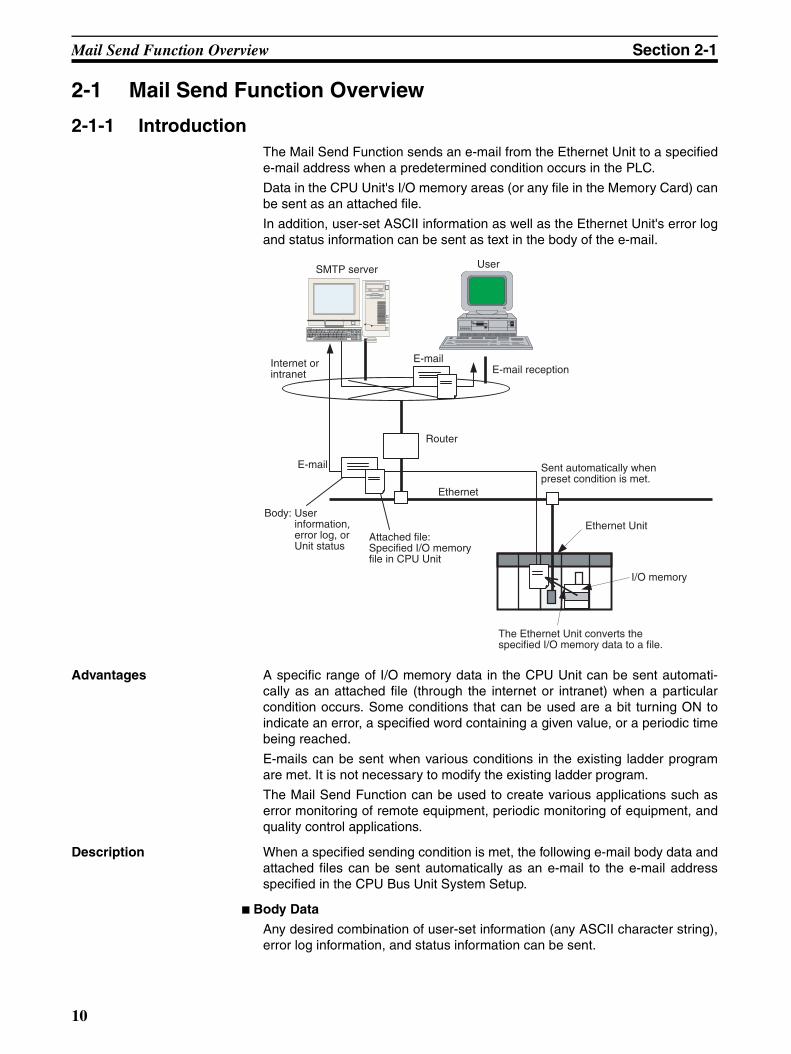
2-1-1 IntroductionThe Mail Send Function sends an e-mail from the Ethernet Unit to a specifiede-mail address when a predetermined condition occurs in the PLC.
Data in the CPU Unit's I/O memory areas (or any file in the Memory Card) canbe sent as an attached file.
In addition, user-set ASCII information as well as the Ethernet Unit's error logand status information can be sent as text in the body of the e-mail.
Advantages A specific range of I/O memory data in the CPU Unit can be sent automati-cally as an attached file (through the internet or intranet) when a particularcondition occurs. Some conditions that can be used are a bit turning ON toindicate an error, a specified word containing a given value, or a periodic timebeing reached.
E-mails can be sent when various conditions in the existing ladder programare met. It is not necessary to modify the existing ladder program.
The Mail Send Function can be used to create various applications such aserror monitoring of remote equipment, periodic monitoring of equipment, andquality control applications.
Description When a specified sending condition is met, the following e-mail body data andattached files can be sent automatically as an e-mail to the e-mail addressspecified in the CPU Bus Unit System Setup.
Body Data
Any desired combination of user-set information (any ASCII character string),error log information, and status information can be sent.
SMTP server User
E-mailE-mail reception
Router
Ethernet Unit
I/O memory
Ethernet
Internet or intranet
Sent automatically when preset condition is met.
Body: User information, error log, or Unit status
Attached file: Specified I/O memory file in CPU Unit
The Ethernet Unit converts the specified I/O memory data to a file.
10
Mail Send Function Details Section 2-2
Attached Files
An I/O memory data file created automatically by the Ethernet Unit (a speci-fied range of the CPU Unit's I/O memory data converted to a .IOM, .TXT, or.CSV file) or any file in file memory (in the CPU Unit's Memory Card) can besent as an attached file.
Send Timing
An e-mail can be sent automatically when a dedicated control bit goes fromOFF to ON, a specified word's value meets a preset condition, a specified bit'sstatus changes, an entry is recorded in the Ethernet Unit's error log, the CPUUnit's status changes (a non-fatal error occurs, a fatal error occurs, or theoperating mode changes), or at periodic intervals.
Send Mail Conditions
Up to 8 send mail conditions can be preset to send an e-mail automaticallywhen the specified conditions are met. Conditions include the send destina-tion, trigger type, I/O memory addresses to be converted to a data file or thename of the file to be read from file memory, and periodic sending interval.
2-1-2 Comparison with the Earlier Mail Send Function
2-1-3 Mail Send Function's Compatibility with Earlier ModelsWhen a CS1W-ETN21 or CJ1W-ETN21 is used to replace a CS1W-ETN01/11 or CJ1W-ETN11 Ethernet Unit in an application, the Unit's functions aredownwardly compatible if the following status bits are used.
2-2 Mail Send Function DetailsThe Mail Send Function can send information in the body of the e-mail as wellas in an attached file.
Item Earlier version Current version
Model CS1W-ETN01/11 and CJ1W-ETN11
CS1W-ETN21CJ1W-ETN21
Attached file Not supported. Supported.A range of I/O memory data can be con-verted to a data file and attached, a file in a Memory Card mounted in the CPU Unit can be attached, or a file in the CPU Unit's EM file memory can be attached.
Send mail con-ditions
Any of the following: A dedicated control bit (the Mail Send Switch) goes OFF to ON, the status of the Ethernet Unit changes (an entry is recorded in the error log), periodic timer
Any of the following:• A dedicated control bit (Mail Send Switch)
goes OFF-to-ON.• A specified word's value changes (=, <>,
<, <=, >=, or > condition).• A specific bit changes (OFF-to-ON or ON-
to-OFF).• Ethernet Unit changes (entry in error log).• CPU Unit changes (non-fatal error occurs,
fatal error occurs, or operating mode changes).
• Periodic timer
ETN01/11 ETN21
User mail send status Status of send condition setting 5
Periodic mail send status Status of send condition setting 6
Error mail send status Status of send condition setting 7
11
Mail Send Function Details Section 2-2
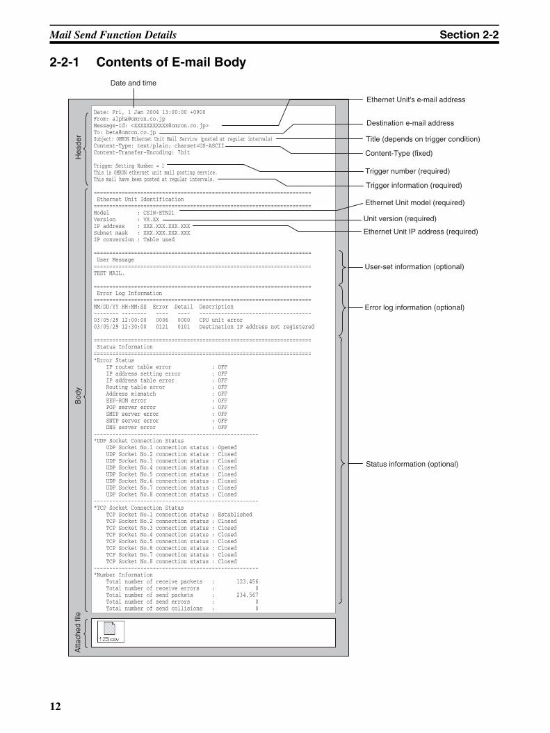
2-2-1 Contents of E-mail Body
Date and time
Ethernet Unit's e-mail address
Destination e-mail address
Title (depends on trigger condition)
Content-Type (fixed)
Trigger number (required)
Trigger information (required)
Ethernet Unit model (required)
Unit version (required)
Ethernet Unit IP address (required)
User-set information (optional)
Error log information (optional)
Status information (optional)
Bod
yA
ttach
ed fi
leH
eade
r
Date: Fri, 1 Jan 2004 13:00:00 +0900From: [email protected]: <[email protected]>To: [email protected]: OMRON Ethernet Unit Mail Service (posted at regular intervals)Content-Type: text/plain; charset=US-ASCIIContent-Transfer-Encoding: 7bit
Trigger Setting Number = 1This is OMRON ethernet unit mail posting service.This mail have been posted at regular intervals.
====================================================================== Ethernet Unit Identification======================================================================Model : CS1W-ETN21 Version : VX.XX IP address : XXX.XXX.XXX.XXXSubnet mask : XXX.XXX.XXX.XXXIP conversion : Table used
====================================================================== User Message======================================================================TEST MAIL.
====================================================================== Error Log Information======================================================================MM/DD/YY HH:MM:SS Error Detail Description-------- -------- ---- ---- ------------------------------------03/05/29 12:00:00 0006 0000 CPU unit error03/05/29 12:30:00 0121 0101 Destination IP address not registered
====================================================================== Status Information======================================================================*Error Status IP router table error : OFF IP address setting error : OFF IP address table error : OFF Routing table error : OFF Address mismatch : OFF EEP-ROM error : OFF POP server error : OFF SMTP server error : OFF SNTP server error : OFF DNS server error : OFF-----------------------------------------------------*UDP Socket Connection Status UDP Socket No.1 connection status : Opened UDP Socket No.2 connection status : Closed UDP Socket No.3 connection status : Closed UDP Socket No.4 connection status : Closed UDP Socket No.5 connection status : Closed UDP Socket No.6 connection status : Closed UDP Socket No.7 connection status : Closed UDP Socket No.8 connection status : Closed-----------------------------------------------------*TCP Socket Connection Status TCP Socket No.1 connection status : Established TCP Socket No.2 connection status : Closed TCP Socket No.3 connection status : Closed TCP Socket No.4 connection status : Closed TCP Socket No.5 connection status : Closed TCP Socket No.6 connection status : Closed TCP Socket No.7 connection status : Closed TCP Socket No.8 connection status : Closed-----------------------------------------------------*Number Information Total number of receive packets : 123,456 Total number of receive errors : 0 Total number of send packets : 234,567 Total number of send errors : 0 Total number of send collisions : 0
12
Mail Send Function Details Section 2-2
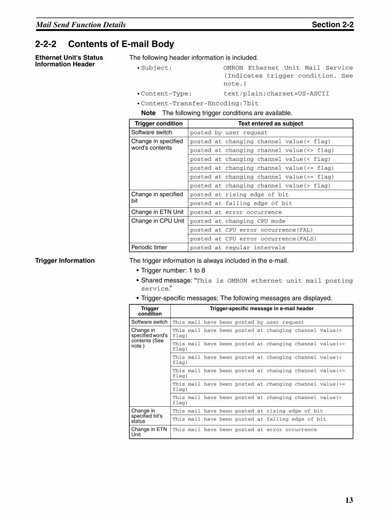
2-2-2 Contents of E-mail BodyEthernet Unit's Status Information Header
The following header information is included.
•Subject: OMRON Ethernet Unit Mail Service(Indicates trigger condition. Seenote.)
•Content-Type: text/plain;charset=US-ASCII
•Content-Transfer-Encoding:7bit
Note The following trigger conditions are available.
Trigger Information The trigger information is always included in the e-mail.
• Trigger number: 1 to 8
• Shared message: “This is OMRON ethernet unit mail postingservice.”
• Trigger-specific messages: The following messages are displayed.
Trigger condition Text entered as subject
Software switch posted by user request
Change in specified word's contents
posted at changing channel value(= flag)
posted at changing channel value(<> flag)
posted at changing channel value(< flag)
posted at changing channel value(<= flag)
posted at changing channel value(>= flag)
posted at changing channel value(> flag)
Change in specified bit
posted at rising edge of bit
posted at falling edge of bit
Change in ETN Unit posted at error occurrence
Change in CPU Unit posted at changing CPU mode
posted at CPU error occurrence(FAL)
posted at CPU error occurrence(FALS)
Periodic timer posted at regular intervals
Trigger condition
Trigger-specific message in e-mail header
Software switch This mail have been posted by user request
Change in specified word's contents (See note.)
This mail have been posted at changing channel value(= flag)
This mail have been posted at changing channel value(<> flag)
This mail have been posted at changing channel value(< flag)
This mail have been posted at changing channel value(<= flag)
This mail have been posted at changing channel value(>= flag)
This mail have been posted at changing channel value(> flag)
Change in specified bit's status
This mail have been posted at rising edge of bit
This mail have been posted at falling edge of bit
Change in ETN Unit
This mail have been posted at error occurrence
13
Mail Send Function Details Section 2-2
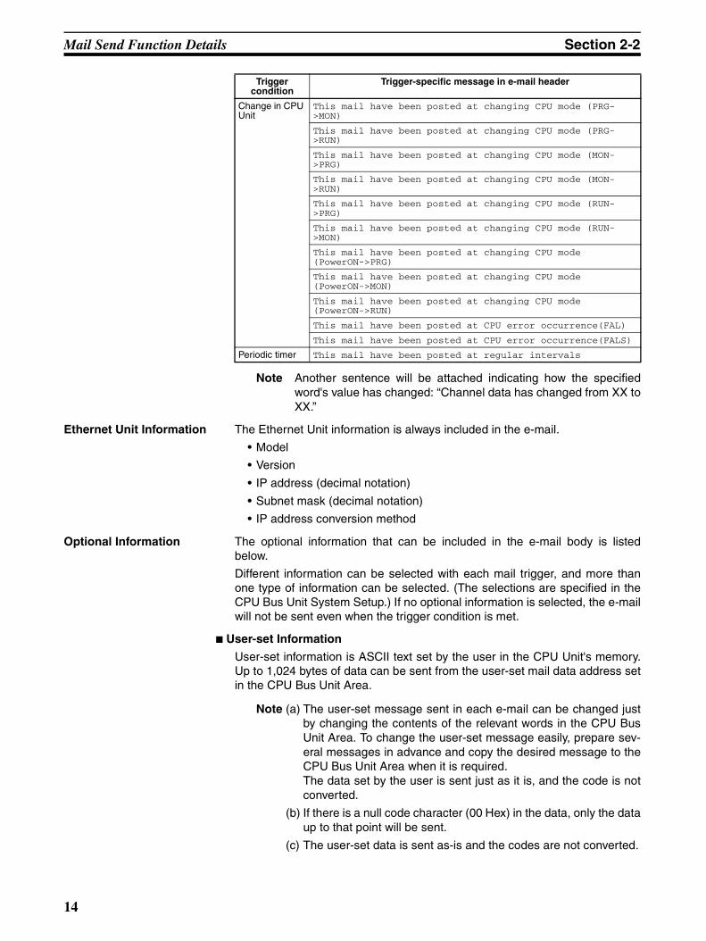
Note Another sentence will be attached indicating how the specifiedword's value has changed: “Channel data has changed from XX toXX.”
Ethernet Unit Information The Ethernet Unit information is always included in the e-mail.
• Model
• Version
• IP address (decimal notation)
• Subnet mask (decimal notation)
• IP address conversion method
Optional Information The optional information that can be included in the e-mail body is listedbelow.
Different information can be selected with each mail trigger, and more thanone type of information can be selected. (The selections are specified in theCPU Bus Unit System Setup.) If no optional information is selected, the e-mailwill not be sent even when the trigger condition is met.
User-set Information
User-set information is ASCII text set by the user in the CPU Unit's memory.Up to 1,024 bytes of data can be sent from the user-set mail data address setin the CPU Bus Unit Area.
Note (a) The user-set message sent in each e-mail can be changed justby changing the contents of the relevant words in the CPU BusUnit Area. To change the user-set message easily, prepare sev-eral messages in advance and copy the desired message to theCPU Bus Unit Area when it is required.The data set by the user is sent just as it is, and the code is notconverted.
(b) If there is a null code character (00 Hex) in the data, only the dataup to that point will be sent.
(c) The user-set data is sent as-is and the codes are not converted.
Change in CPU Unit
This mail have been posted at changing CPU mode (PRG->MON)
This mail have been posted at changing CPU mode (PRG->RUN)
This mail have been posted at changing CPU mode (MON->PRG)
This mail have been posted at changing CPU mode (MON->RUN)
This mail have been posted at changing CPU mode (RUN->PRG)
This mail have been posted at changing CPU mode (RUN->MON)
This mail have been posted at changing CPU mode (PowerON->PRG)
This mail have been posted at changing CPU mode (PowerON->MON)
This mail have been posted at changing CPU mode (PowerON->RUN)
This mail have been posted at CPU error occurrence(FAL)
This mail have been posted at CPU error occurrence(FALS)
Periodic timer This mail have been posted at regular intervals
Trigger condition
Trigger-specific message in e-mail header
14
Mail Send Function Details Section 2-2
Error Log Information
The error log information includes all of the data stored in the Ethernet Unit'serror log. The error log can contain up to 64 records. For details on the errorlog, refer to 8-3 Error Log in the Operation Manual Construction of Networks(W420).
Status Information
The following Ethernet Unit data is sent.
1. Open/closed status of UDP sockets 1 to 8
2. TCP status of TCP sockets 1 to 8
3. Unit error information
4. Counter informationTotal number of receive packets, total number of receive errors, total num-ber of send packets, total number of send errors, total number of send col-lisions
2-2-3 Attached File DetailsFiles that can be attached to e-mails are broadly divided into the following 2groups.
• I/O memory data (IOM, TXT, and CSV formats)
• File data
Only one file can be attached to each e-mail.
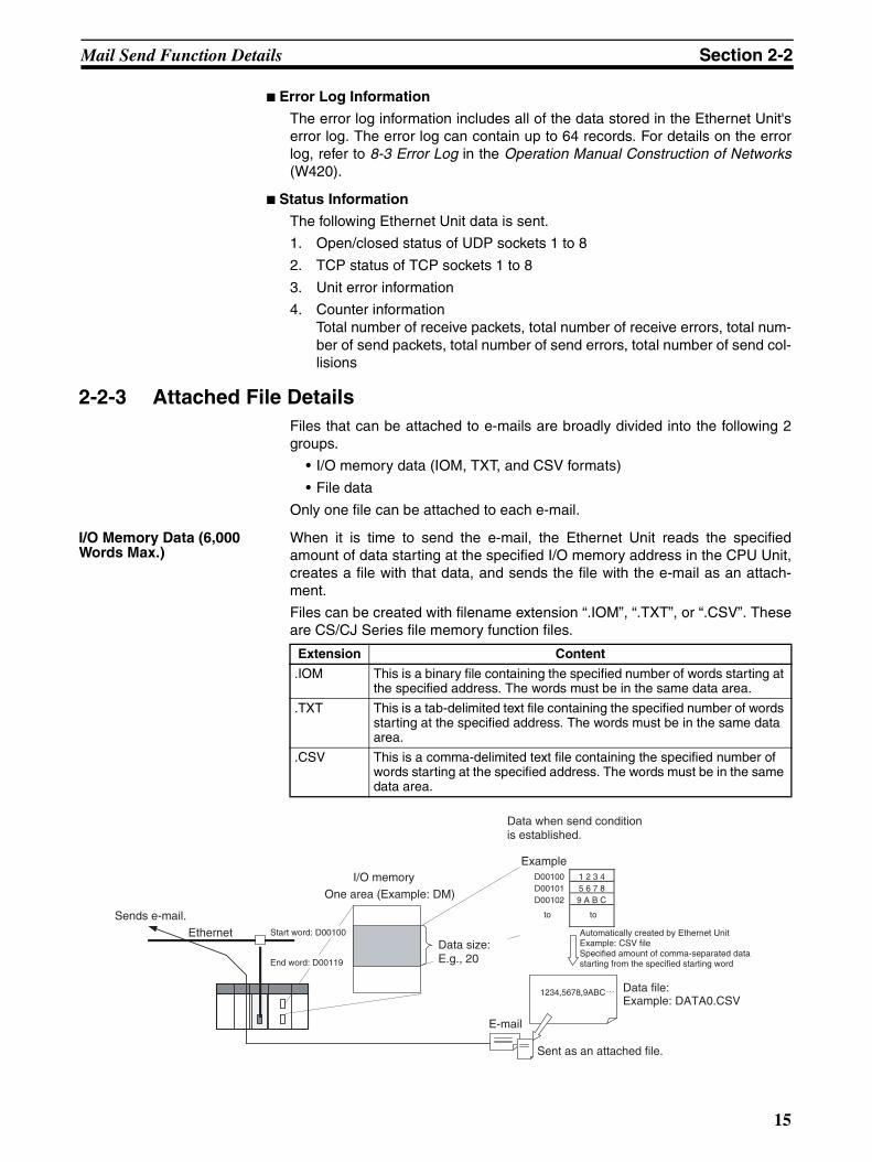
I/O Memory Data (6,000 Words Max.)
When it is time to send the e-mail, the Ethernet Unit reads the specifiedamount of data starting at the specified I/O memory address in the CPU Unit,creates a file with that data, and sends the file with the e-mail as an attach-ment.
Files can be created with filename extension “.IOM”, “.TXT”, or “.CSV”. Theseare CS/CJ Series file memory function files.
Extension Content
.IOM This is a binary file containing the specified number of words starting at the specified address. The words must be in the same data area.
.TXT This is a tab-delimited text file containing the specified number of words starting at the specified address. The words must be in the same data area.
.CSV This is a comma-delimited text file containing the specified number of words starting at the specified address. The words must be in the same data area.
1234,5678,9ABC
D00100 1 2 3 4 D00101 5 6 7 8 D00102 9 A B C
EthernetSends e-mail.
Start word: D00100
End word: D00119
I/O memoryOne area (Example: DM)
Data size: E.g., 20
Data when send condition is established.
Example
to to
Automatically created by Ethernet UnitExample: CSV fileSpecified amount of comma-separated data starting from the specified starting word
Data file:Example: DATA0.CSV
Sent as an attached file.
15
Mail Send Function Details Section 2-2
• Since the Ethernet Unit creates the data file automatically, the AccessingMemory/Sending Mail Flag (bit 01 of n+17 in the allocated CPU Bus UnitArea) will be ON while the CPU Unit's I/O memory is being accessed.
• To maintain the integrity of the data, write-protect the region of I/O mem-ory being converted to a data file by preventing the region from being writ-ten from the ladder program while this flag is ON.
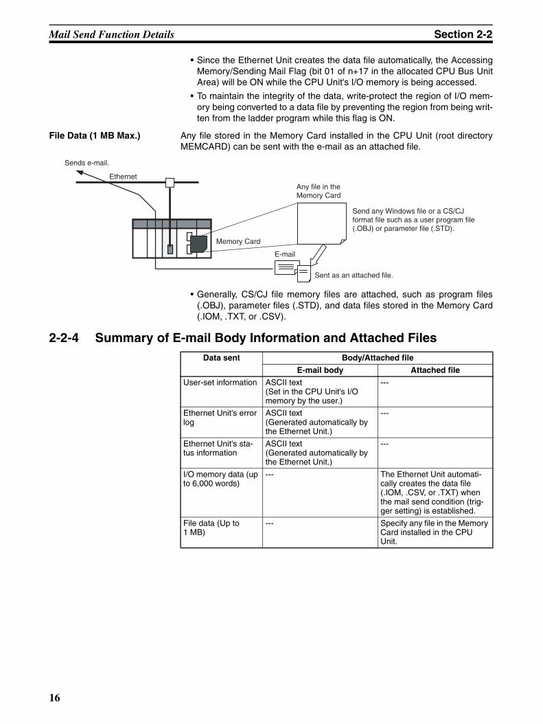
File Data (1 MB Max.) Any file stored in the Memory Card installed in the CPU Unit (root directoryMEMCARD) can be sent with the e-mail as an attached file.
• Generally, CS/CJ file memory files are attached, such as program files(.OBJ), parameter files (.STD), and data files stored in the Memory Card(.IOM, .TXT, or .CSV).
2-2-4 Summary of E-mail Body Information and Attached Files
Sends e-mail.
Ethernet
Memory Card
Sent as an attached file.
Any file in the Memory Card
Send any Windows file or a CS/CJ format file such as a user program file (.OBJ) or parameter file (.STD).
Data sent Body/Attached file
E-mail body Attached file
User-set information ASCII text(Set in the CPU Unit's I/O memory by the user.)
---
Ethernet Unit's error log
ASCII text(Generated automatically by the Ethernet Unit.)
---
Ethernet Unit's sta-tus information
ASCII text(Generated automatically by the Ethernet Unit.)
---
I/O memory data (up to 6,000 words)
--- The Ethernet Unit automati-cally creates the data file (.IOM, .CSV, or .TXT) when the mail send condition (trig-ger setting) is established.
File data (Up to 1 MB)
--- Specify any file in the Memory Card installed in the CPU Unit.
16
Mail Send Function Specifications Section 2-3
2-3 Mail Send Function Specifications
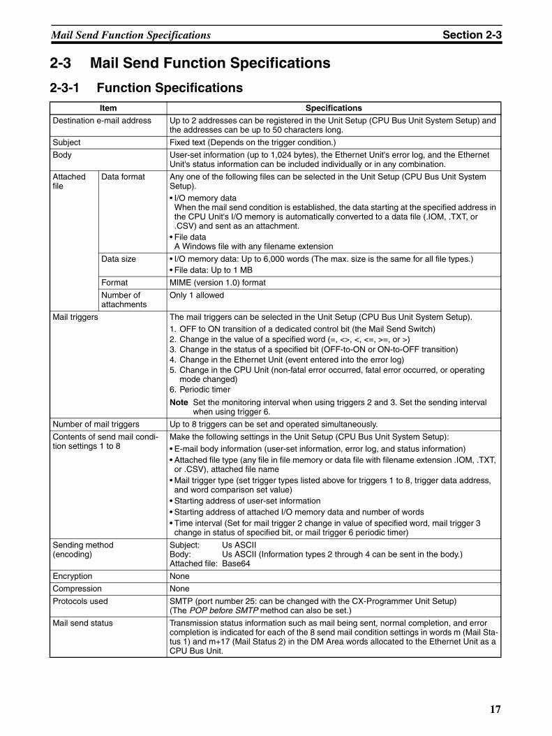
2-3-1 Function SpecificationsItem Specifications
Destination e-mail address Up to 2 addresses can be registered in the Unit Setup (CPU Bus Unit System Setup) and the addresses can be up to 50 characters long.
Subject Fixed text (Depends on the trigger condition.)
Body User-set information (up to 1,024 bytes), the Ethernet Unit's error log, and the Ethernet Unit's status information can be included individually or in any combination.
Attached file
Data format Any one of the following files can be selected in the Unit Setup (CPU Bus Unit System Setup).• I/O memory data
When the mail send condition is established, the data starting at the specified address in the CPU Unit's I/O memory is automatically converted to a data file (.IOM, .TXT, or .CSV) and sent as an attachment.
• File dataA Windows file with any filename extension
Data size • I/O memory data: Up to 6,000 words (The max. size is the same for all file types.)• File data: Up to 1 MB
Format MIME (version 1.0) format
Number of attachments
Only 1 allowed
Mail triggers The mail triggers can be selected in the Unit Setup (CPU Bus Unit System Setup).1. OFF to ON transition of a dedicated control bit (the Mail Send Switch)2. Change in the value of a specified word (=, <>, <, <=, >=, or >)3. Change in the status of a specified bit (OFF-to-ON or ON-to-OFF transition)4. Change in the Ethernet Unit (event entered into the error log)5. Change in the CPU Unit (non-fatal error occurred, fatal error occurred, or operating
mode changed)6. Periodic timer
Note Set the monitoring interval when using triggers 2 and 3. Set the sending interval when using trigger 6.
Number of mail triggers Up to 8 triggers can be set and operated simultaneously.
Contents of send mail condi-tion settings 1 to 8
Make the following settings in the Unit Setup (CPU Bus Unit System Setup):• E-mail body information (user-set information, error log, and status information)• Attached file type (any file in file memory or data file with filename extension .IOM, .TXT,
or .CSV), attached file name• Mail trigger type (set trigger types listed above for triggers 1 to 8, trigger data address,
and word comparison set value)• Starting address of user-set information• Starting address of attached I/O memory data and number of words• Time interval (Set for mail trigger 2 change in value of specified word, mail trigger 3
change in status of specified bit, or mail trigger 6 periodic timer)
Sending method(encoding)
Subject: Us ASCIIBody: Us ASCII (Information types 2 through 4 can be sent in the body.)Attached file: Base64
Encryption None
Compression None
Protocols used SMTP (port number 25: can be changed with the CX-Programmer Unit Setup)(The POP before SMTP method can also be set.)
Mail send status Transmission status information such as mail being sent, normal completion, and error completion is indicated for each of the 8 send mail condition settings in words m (Mail Sta-tus 1) and m+17 (Mail Status 2) in the DM Area words allocated to the Ethernet Unit as a CPU Bus Unit.
17
Using the Mail Send Function Section 2-4
2-3-2 Details of the Available Mail Triggers
2-4 Using the Mail Send Function
2-4-1 Procedure
Note The Ethernet Unit will be restarted when the settings data is transferred to theCPU Bus Unit System Setup Area, so that the new settings are read and
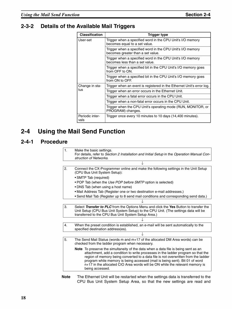
Classification Trigger type
User-set Trigger when a specified word in the CPU Unit's I/O memory becomes equal to a set value.
Trigger when a specified word in the CPU Unit's I/O memory becomes greater than a set value.
Trigger when a specified word in the CPU Unit's I/O memory becomes less than a set value.
Trigger when a specified bit in the CPU Unit's I/O memory goes from OFF to ON.
Trigger when a specified bit in the CPU Unit's I/O memory goes from ON to OFF.
Change in sta-tus
Trigger when an event is registered in the Ethernet Unit's error log.
Trigger when an error occurs in the Ethernet Unit.
Trigger when a fatal error occurs in the CPU Unit.
Trigger when a non-fatal error occurs in the CPU Unit.
Trigger when the CPU Unit's operating mode (RUN, MONITOR, or PROGRAM) changes.
Periodic inter-vals
Trigger once every 10 minutes to 10 days (14,400 minutes).
1. Make the basic settings.For details, refer to Section 2 Installation and Initial Setup in the Operation Manual Con-struction of Networks.
↓2. Connect the CX-Programmer online and make the following settings in the Unit Setup
(CPU Bus Unit System Setup):
• SMTP Tab (required)• POP Tab (when the Use POP before SMTP option is selected)• DNS Tab (when using a host name)• Mail Address Tab (Register one or two destination e-mail addresses.)• Send Mail Tab (Register up to 8 send mail conditions and corresponding send data.)
↓3. Select Transfer to PLC from the Options Menu and click the Yes Button to transfer the
Unit Setup (CPU Bus Unit System Setup) to the CPU Unit. (The settings data will be transferred to the CPU Bus Unit System Setup Area.)
↓4. When the preset condition is established, an e-mail will be sent automatically to the
specified destination address(es).
↓5. The Send Mail Status (words m and m+17 of the allocated DM Area words) can be
checked from the ladder program when necessary.
Note To preserve the simultaneity of the data when a data file is being sent as an attachment, add a condition to write processes in the ladder program so that the region of memory being converted to a data file is not overwritten from the ladder program while memory is being accessed (mail is being sent). Bit 01 of word n+17 in the allocated CIO Area words will be ON while the relevant memory is being accessed.
18
Using the Mail Send Function Section 2-4
become effective. Verify that it is safe for the Ethernet Unit to restart beforetransferring the settings data.
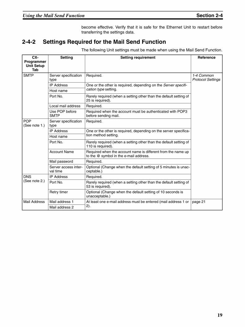
2-4-2 Settings Required for the Mail Send FunctionThe following Unit settings must be made when using the Mail Send Function.
CX-Programmer Unit Setup
Tab
Setting Setting requirement Reference
SMTP Server specification type
Required. 1-4 Common Protocol Settings
IP Address One or the other is required, depending on the Server specifi-cation type setting.Host name
Port No. Rarely required (when a setting other than the default setting of 25 is required).
Local mail address Required.
Use POP before SMTP
Required when the account must be authenticated with POP3 before sending mail.
POP(See note 1.)
Server specification type
Required.
IP Address One or the other is required, depending on the server specifica-tion method setting.Host name
Port No. Rarely required (when a setting other than the default setting of 110 is required).
Account Name Required when the account name is different from the name up to the @ symbol in the e-mail address.
Mail password Required.
Server access inter-val time
Optional (Change when the default setting of 5 minutes is unac-ceptable.)
DNS(See note 2.)
IP Address Required.
Port No. Rarely required (when a setting other than the default setting of 53 is required).
Retry timer Optional (Change when the default setting of 10 seconds is unacceptable.)
Mail Address Mail address 1 At least one e-mail address must be entered (mail address 1 or 2).
page 21
Mail address 2
19
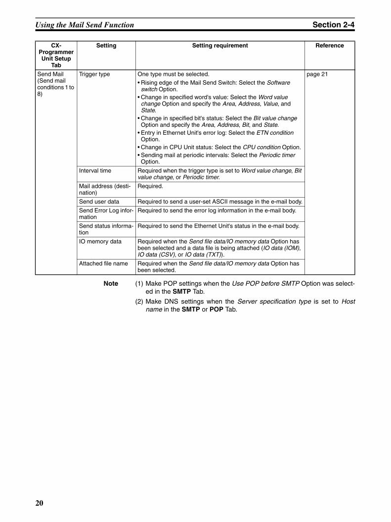
Using the Mail Send Function Section 2-4
Note (1) Make POP settings when the Use POP before SMTP Option was select-ed in the SMTP Tab.
(2) Make DNS settings when the Server specification type is set to Hostname in the SMTP or POP Tab.
Send Mail(Send mail conditions 1 to 8)
Trigger type One type must be selected.• Rising edge of the Mail Send Switch: Select the Software
switch Option.• Change in specified word's value: Select the Word value
change Option and specify the Area, Address, Value, and State.
• Change in specified bit's status: Select the Bit value change Option and specify the Area, Address, Bit, and State.
• Entry in Ethernet Unit's error log: Select the ETN condition Option.
• Change in CPU Unit status: Select the CPU condition Option.• Sending mail at periodic intervals: Select the Periodic timer
Option.
page 21
Interval time Required when the trigger type is set to Word value change, Bit value change, or Periodic timer.
Mail address (desti-nation)
Required.
Send user data Required to send a user-set ASCII message in the e-mail body.
Send Error Log infor-mation
Required to send the error log information in the e-mail body.
Send status informa-tion
Required to send the Ethernet Unit's status in the e-mail body.
IO memory data Required when the Send file data/IO memory data Option has been selected and a data file is being attached (IO data (IOM), IO data (CSV), or IO data (TXT)).
Attached file name Required when the Send file data/IO memory data Option has been selected.
CX-Programmer Unit Setup
Tab
Setting Setting requirement Reference
20
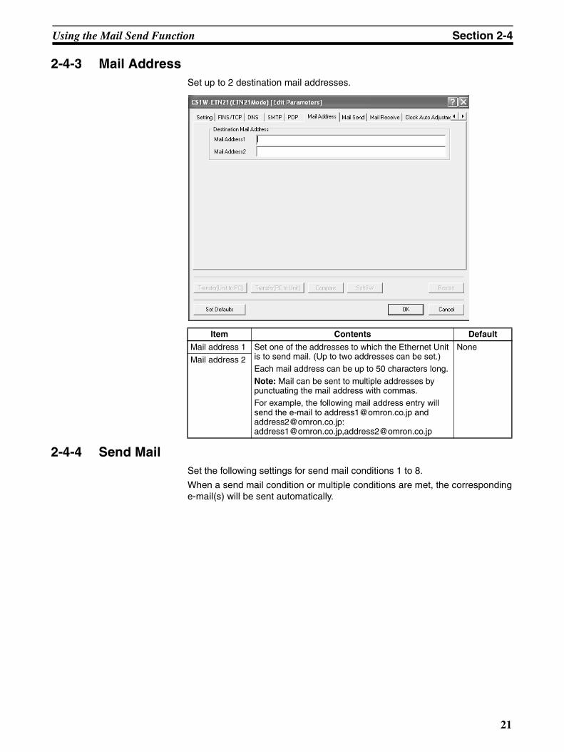
Using the Mail Send Function Section 2-4
2-4-3 Mail AddressSet up to 2 destination mail addresses.
2-4-4 Send MailSet the following settings for send mail conditions 1 to 8.
When a send mail condition or multiple conditions are met, the correspondinge-mail(s) will be sent automatically.
Item Contents Default
Mail address 1 Set one of the addresses to which the Ethernet Unit is to send mail. (Up to two addresses can be set.)Each mail address can be up to 50 characters long.
Note: Mail can be sent to multiple addresses by punctuating the mail address with commas.For example, the following mail address entry will send the e-mail to [email protected] and [email protected]:[email protected],[email protected]
None
Mail address 2
21
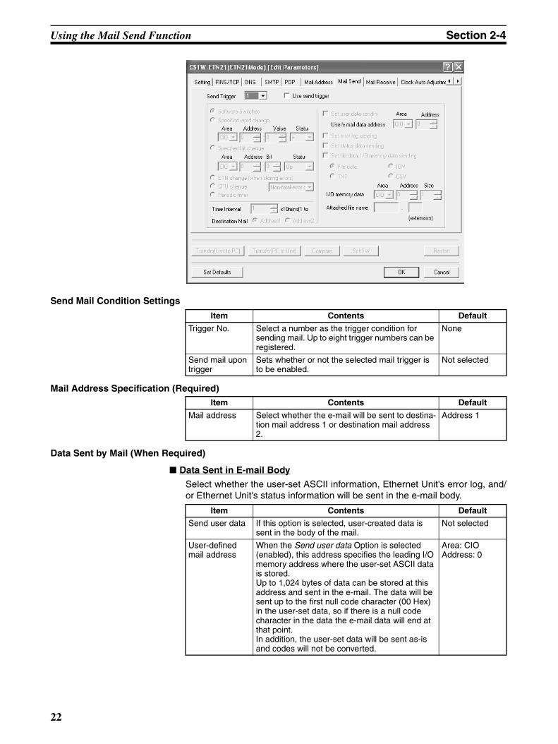
Using the Mail Send Function Section 2-4
Send Mail Condition Settings
Mail Address Specification (Required)
Data Sent by Mail (When Required)
Data Sent in E-mail Body
Select whether the user-set ASCII information, Ethernet Unit's error log, and/or Ethernet Unit's status information will be sent in the e-mail body.
Item Contents Default
Trigger No. Select a number as the trigger condition for sending mail. Up to eight trigger numbers can be registered.
None
Send mail upon trigger
Sets whether or not the selected mail trigger is to be enabled.
Not selected
Item Contents Default
Mail address Select whether the e-mail will be sent to destina-tion mail address 1 or destination mail address 2.
Address 1
Item Contents Default
Send user data If this option is selected, user-created data is sent in the body of the mail.
Not selected
User-defined mail address
When the Send user data Option is selected (enabled), this address specifies the leading I/O memory address where the user-set ASCII data is stored.Up to 1,024 bytes of data can be stored at this address and sent in the e-mail. The data will be sent up to the first null code character (00 Hex) in the user-set data, so if there is a null code character in the data the e-mail data will end at that point.In addition, the user-set data will be sent as-is and codes will not be converted.
Area: CIOAddress: 0
22
Using the Mail Send Function Section 2-4
Data Sent in an Attached File
These settings specify whether a file will be attached to the e-mail as well asthe contents of the attached file if one is being attached.
Attached File Name
Send Mail Trigger Type Setting (Required)
Specifies the type send mail condition that will be used by the Ethernet Unit toautomatically send e-mail.
When the Mail Send Function is not being used, disable the send mail upontrigger setting.
Send Error Log information
Selects whether or not the Ethernet Unit's error log will be included in the body of the e-mail.
Not selected
Send status information
Selects whether or not status information will be included in the body of the e-mail.
Not selected
Item Contents Default
Item Contents Default
Send file data or I/O memory data
This option selects whether or not a file will be attached to the e-mail.
Not selected
Attached file type
Select one of the following file types.• I/O data (.IOM)• I/O data (.TXT)• I/O data (.CSV)• File data (any file in file memory)
File data
IO memory data If an I/O data file (.IOM, .TXT, or .CSV) is selected as the attached file type, this setting specifies the leading address where the data is stored and the number of words of data that the Ethernet Unit will convert to a file.
Area: CIOAddress: 0Size: 1
Item Contents Default
Attached file name
If the above setting is checked so that files can be sent as attachments, then specify the name of the file that is to be sent.
None
I/O data file selected
The data file will be created auto-matically with the file name entered in this field.
Note Even if a filename extension is entered, it will be ignored. The Unit automatically adds the appropriate extension (.IOM, .TXT, or .CSV).
File data file selected
The file with the specified filename will be read from the Memory Card's root directory and attached to the e-mail.
Note The file must be located in the Memory Card's root directory in order to be sent as an attachment.
23
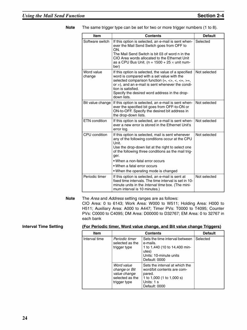
Using the Mail Send Function Section 2-4
Note The same trigger type can be set for two or more trigger numbers (1 to 8).
Note The Area and Address setting ranges are as follows:CIO Area: 0 to 6143; Work Area: W000 to W511; Holding Area: H000 toH511; Auxiliary Area: A000 to A447; Timer PVs: T0000 to T4095; CounterPVs: C0000 to C4095; DM Area: D00000 to D32767; EM Area: 0 to 32767 ineach bank
Interval Time Setting (For Periodic timer, Word value change, and Bit value change Triggers)
Item Contents Default
Software switch If this option is selected, an e-mail is sent when-ever the Mail Send Switch goes from OFF to ON.The Mail Send Switch is bit 03 of word n in the CIO Area words allocated to the Ethernet Unit as a CPU Bus Unit. (n = 1500 + 25 × unit num-ber)
Selected
Word value change
If this option is selected, the value of a specified word is compared with a set value with the selected comparison function (=, <>, <, <=, >=, or >), and an e-mail is sent whenever the condi-tion is satisfied.Specify the desired word address in the drop-down lists.
Not selected
Bit value change If this option is selected, an e-mail is sent when-ever the specified bit goes from OFF-to-ON or ON-to-OFF. Specify the desired bit address in the drop-down lists.
Not selected
ETN condition If this option is selected, an e-mail is sent when-ever a new error is stored in the Ethernet Unit's error log.
Not selected
CPU condition If this option is selected, mail is sent whenever any of the following conditions occur at the CPU Unit.Use the drop-down list at the right to select one of the following three conditions as the mail trig-ger.• When a non-fatal error occurs• When a fatal error occurs• When the operating mode is changed
Not selected
Periodic timer If this option is selected, an e-mail is sent at fixed time intervals. The time interval is set in 10-minute units in the Interval time box. (The mini-mum interval is 10 minutes.)
Not selected
Item Contents Default
Interval time Periodic timer selected as the trigger type
Sets the time interval between e-mails.1 to 1,440 (10 to 14,400 min-utes)Units: 10-minute unitsDefault: 0000
Selected
Word value change or Bit value change selected as the trigger type
Sets the interval at which the word/bit contents are com-pared.1 to 1,000 (1 to 1,000 s) Units: 1 sDefault: 0000
24
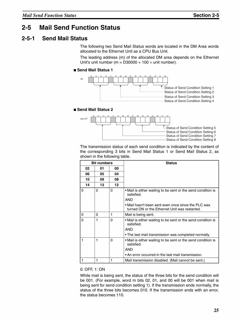
Mail Send Function Status Section 2-5
2-5 Mail Send Function Status
2-5-1 Send Mail StatusThe following two Send Mail Status words are located in the DM Area wordsallocated to the Ethernet Unit as a CPU Bus Unit.
The leading address (m) of the allocated DM area depends on the EthernetUnit's unit number (m = D30000 + 100 × unit number).
Send Mail Status 1
Send Mail Status 2
The transmission status of each send condition is indicated by the content ofthe corresponding 3 bits in Send Mail Status 1 or Send Mail Status 2, asshown in the following table.
0: OFF, 1: ON
While mail is being sent, the status of the three bits for the send condition willbe 001. (For example, word m bits 02, 01, and 00 will be 001 when mail isbeing sent for send condition setting 1). If the transmission ends normally, thestatus of the three bits becomes 010. If the transmission ends with an error,the status becomes 110.
15 14 13 12 11 10 09 08 07 06 05 04 03 02 01 00
m
Status of Send Condition Setting 1Status of Send Condition Setting 2
Status of Send Condition Setting 3Status of Send Condition Setting 4
Bit numbers Status
02 01 00
06 05 04
10 09 08
14 13 12
0 0 0 • Mail is either waiting to be sent or the send condition is satisfied.
AND• Mail hasn't been sent even once since the PLC was
turned ON or the Ethernet Unit was restarted.
0 0 1 Mail is being sent.
0 1 0 • Mail is either waiting to be sent or the send condition is satisfied.
AND• The last mail transmission was completed normally.
1 1 0 • Mail is either waiting to be sent or the send condition is satisfied.
AND• An error occurred in the last mail transmission.
1 1 1 Mail transmission disabled. (Mail cannot be sent.)
15 14 13 12 11 10 09 08 07 06 05 04 03 02 01 00
m+17
Status of Send Condition Setting 5Status of Send Condition Setting 6Status of Send Condition Setting 7Status of Send Condition Setting 8
25
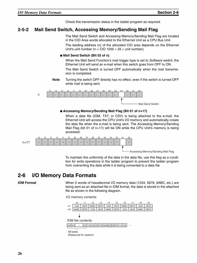
I/O Memory Data Formats Section 2-6
Check this transmission status in the ladder program as required.
2-5-2 Mail Send Switch, Accessing Memory/Sending Mail FlagThe Mail Send Switch and Accessing Memory/Sending Mail Flag are locatedin the CIO Area words allocated to the Ethernet Unit as a CPU Bus Unit.
The leading address (n) of the allocated CIO area depends on the EthernetUnit's unit number (n = CIO 1500 + 25 × unit number).
Mail Send Switch (Bit 03 of n)
When the Mail Send Function's mail trigger type is set to Software switch, theEthernet Unit will send an e-mail when this switch goes from OFF to ON.
The Mail Send Switch is turned OFF automatically when the mail transmis-sion is completed.
Note Turning the switch OFF directly has no effect, even if the switch is turned OFFwhile mail is being sent.
Accessing Memory/Sending Mail Flag (Bit 01 of n+17)
When a data file (IOM, TXT, or CSV) is being attached to the e-mail, theEthernet Unit will access the CPU Unit's I/O memory and automatically createthe data file when the e-mail is being sent. The Accessing Memory/SendingMail Flag (bit 01 of n+17) will be ON while the CPU Unit's memory is beingaccessed.
To maintain the uniformity of the data in the data file, use this flag as a condi-tion for write operations in the ladder program to prevent the ladder programfrom overwriting the data while it is being converted to a data file.
2-6 I/O Memory Data FormatsIOM Format When 5 words of hexadecimal I/O memory data (1234, 5678, 9ABC, etc.) are
being sent as an attached file in IOM format, the data is stored in the attachedfile as shown in the following diagram.
15 14 13 12 11 10 09 08 07 06 05 04 03 02 01 00
- - - - - - - - - - - - - - -n
Mail Send Switch
15 14 13 12 11 10 09 08 07 06 05 04 03 02 01 00
n+17 - - - - - - - - - - - - - - -
Accessing Memory/Sending Mail Flag
+0 +1 +2 +3 +4 +5 +6 +7 +8 +9
+0 1234 5678 9ABC DEF0 1234 5678 9ABC DEF0 1234 5678
+10 9ABC DEF0 1234 5678 9ABC DEF0 1234 5678 9ABC DEF0
XX XX XX 12 34 56 78 9A BC DE F0 12 34
I/O memory contents
IOM file contents
48 bytes (Reserved for system)
26
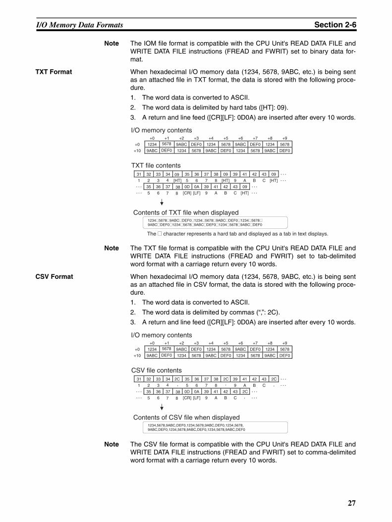
I/O Memory Data Formats Section 2-6
Note The IOM file format is compatible with the CPU Unit's READ DATA FILE andWRITE DATA FILE instructions (FREAD and FWRIT) set to binary data for-mat.
TXT Format When hexadecimal I/O memory data (1234, 5678, 9ABC, etc.) is being sentas an attached file in TXT format, the data is stored with the following proce-dure.
1. The word data is converted to ASCII.
2. The word data is delimited by hard tabs ([HT]: 09).
3. A return and line feed ([CR][LF]: 0D0A) are inserted after every 10 words.
Note The TXT file format is compatible with the CPU Unit's READ DATA FILE andWRITE DATA FILE instructions (FREAD and FWRIT) set to tab-delimitedword format with a carriage return every 10 words.
CSV Format When hexadecimal I/O memory data (1234, 5678, 9ABC, etc.) is being sentas an attached file in CSV format, the data is stored with the following proce-dure.
1. The word data is converted to ASCII.
2. The word data is delimited by commas (“,”: 2C).
3. A return and line feed ([CR][LF]: 0D0A) are inserted after every 10 words.
Note The CSV file format is compatible with the CPU Unit's READ DATA FILE andWRITE DATA FILE instructions (FREAD and FWRIT) set to comma-delimitedword format with a carriage return every 10 words.
+0 +1 +2 +3 +4 +5 +6 +7 +8 +9
+0 1234 5678 9ABC DEF0 1234 5678 9ABC DEF0 1234 5678
+10 9ABC DEF0 1234 5678 9ABC DEF0 1234 5678 9ABC DEF0
31 32 33 34 09 35 36 37 38 09 39 41 42 43 09
1 2 3 4 [HT] 5 6 7 8 [HT] 9 A B C [HT]
35 36 37 38 0D 0A 39 41 42 43 09
5 6 7 8 [CR] [LF] 9 A B C [HT]
1234@5678@9ABC@DEF0@1234@5678@9ABC@DEF0@1234@5678@ 9ABC@DEF0@1234@5678@9ABC@DEF0@1234@5678@9ABC@DEF0
The @ character represents a hard tab and displayed as a tab in text displays.
I/O memory contents
TXT file contents
Contents of TXT file when displayed
+0 +1 +2 +3 +4 +5 +6 +7 +8 +9
+0 1234 5678 9ABC DEF0 1234 5678 9ABC DEF0 1234 5678
+10 9ABC DEF0 1234 5678 9ABC DEF0 1234 5678 9ABC DEF0
31 32 33 34 2C 35 36 37 38 2C 39 41 42 43 2C
1 2 3 4 5 6 7 8 9 A B C
35 36 37 38 0D 0A 39 41 42 43 2C
5 6 7 8 [CR] [LF] 9 A B C
1234,5678,9ABC,DEF0,1234,5678,9ABC,DEF0,1234,5678, 9ABC,DEF0,1234,5678,9ABC,DEF0,1234,5678,9ABC,DEF0
I/O memory contents
CSV file contents
Contents of CSV file when displayed
,
,
,,
27
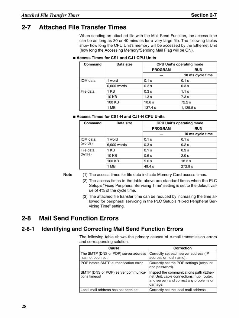
Attached File Transfer Times Section 2-7
2-7 Attached File Transfer TimesWhen sending an attached file with the Mail Send Function, the access timecan be as long as 30 or 40 minutes for a very large file. The following tablesshow how long the CPU Unit's memory will be accessed by the Ethernet Unit(how long the Accessing Memory/Sending Mail Flag will be ON).
Access Times for CS1 and CJ1 CPU Units
Access Times for CS1-H and CJ1-H CPU Units
Note (1) The access times for file data indicate Memory Card access times.
(2) The access times in the table above are standard times when the PLCSetup's “Fixed Peripheral Servicing Time” setting is set to the default val-ue of 4% of the cycle time.
(3) The attached file transfer time can be reduced by increasing the time al-lowed for peripheral servicing in the PLC Setup's “Fixed Peripheral Ser-vicing Time” setting.
2-8 Mail Send Function Errors
2-8-1 Identifying and Correcting Mail Send Function ErrorsThe following table shows the primary causes of e-mail transmission errorsand corresponding solution.
Command Data size CPU Unit's operating mode
PROGRAM RUN
--- 10 ms cycle time
IOM data 1 word 0.1 s 0.1 s
6,000 words 0.3 s 0.3 s
File data 1 KB 0.3 s 1.1 s
10 KB 1.3 s 7.3 s
100 KB 10.6 s 72.2 s
1 MB 137.4 s 1,139.5 s
Command Data size CPU Unit's operating mode
PROGRAM RUN
--- 10 ms cycle time
IOM data (words)
1 word 0.1 s 0.1 s
6,000 words 0.3 s 0.2 s
File data (bytes)
1 KB 0.1 s 0.3 s
10 KB 0.6 s 2.0 s
100 KB 5.0 s 18.3 s
1 MB 49.4 s 272.8 s
Cause Correction
The SMTP (DNS or POP) server address has not been set.
Correctly set each server address (IP address or host name).
POP before SMTP authentication error Correctly set the POP settings (account and password).
SMTP (DNS or POP) server communica-tions timeout
Inspect the communications path (Ether-net Unit, cable connections, hub, router, and server) and correct any problems or damage.
Local mail address has not been set. Correctly set the local mail address.
28
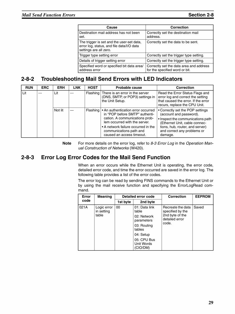
Mail Send Function Errors Section 2-8
2-8-2 Troubleshooting Mail Send Errors with LED Indicators
Note For more details on the error log, refer to 8-3 Error Log in the Operation Man-ual Construction of Networks (W420).
2-8-3 Error Log Error Codes for the Mail Send FunctionWhen an error occurs while the Ethernet Unit is operating, the error code,detailed error code, and time the error occurred are saved in the error log. Thefollowing table provides a list of the error codes.
The error log can be read by sending FINS commands to the Ethernet Unit orby using the mail receive function and specifying the ErrorLogRead com-mand.
Destination mail address has not been set.
Correctly set the destination mail address.
The trigger is set and the user-set data, error log, status, and file data/I/O data settings are all zero.
Correctly set the data to be sent.
Trigger type setting error Correctly set the trigger type setting.
Details of trigger setting error Correctly set the trigger type setting.
Specified word or specified bit data area/address error
Correctly set the data area and address for the specified word or bit.
Cause Correction
RUN ERC ERH LNK HOST Probable cause Correction
Lit --- Lit --- Flashing There is an error in the server (DNS, SMTP, or POP3) settings in the Unit Setup.
Read the Error Status Flags and error log and correct the setting that caused the error. If the error recurs, replace the CPU Unit.
Not lit --- Flashing • An authentication error occurred in “POP before SMTP” authenti-cation. A communications prob-lem occurred with the server.
• A network failure occurred in the communications path and caused an access timeout.
• Correctly set the POP settings (account and password).
• Inspect the communications path (Ethernet Unit, cable connec-tions, hub, router, and server) and correct any problems or damage.
Error code
Meaning Detailed error code Correction EEPROM
1st byte 2nd byte
021A Logic error in setting table
00 01: Data link table02: Network parameters
03: Routing tables04: Setup
05: CPU Bus Unit Words (CIO/DM)
Recreate the data specified by the 2nd byte of the detailed error code.
Saved
29
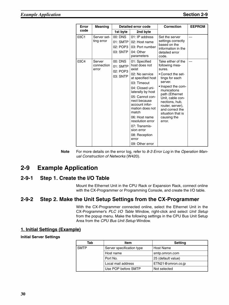
Example Application Section 2-9
Note For more details on the error log, refer to 8-3 Error Log in the Operation Man-ual Construction of Networks (W420).
2-9 Example Application
2-9-1 Step 1. Create the I/O TableMount the Ethernet Unit in the CPU Rack or Expansion Rack, connect onlinewith the CX-Programmer or Programming Console, and create the I/O table.
2-9-2 Step 2. Make the Unit Setup Settings from the CX-ProgrammerWith the CX-Programmer connected online, select the Ethernet Unit in theCX-Programmer's PLC I/O Table Window, right-click and select Unit Setupfrom the popup menu. Make the following settings in the CPU Bus Unit SetupArea from the CPU Bus Unit Setup Window.
1. Initial Settings (Example)
Initial Server Settings
03C1 Server set-ting error
00: DNS01: SMTP02: POP3
03: SNTP
01: IP address02: Host name03: Port number
04: Other parameters
Set the server settings correctly based on the information in the detailed error code.
---
03C4 Server connection error
00: DNS01: SMTP02: POP3
03: SNTP
01: Specified host does not exist
02: No service at specified host03: Timeout
04: Closed uni-laterally by host05: Cannot con-nect because account infor-mation does not match06: Host name resolution error
07: Transmis-sion error08: Reception error09: Other error
Take either of the following mea-sures.
• Correct the set-tings for each server.
• Inspect the com-munications path (Ethernet Unit, cable con-nections, hub, router, server), and correct the situation that is causing the error.
---
Error code
Meaning Detailed error code Correction EEPROM
1st byte 2nd byte
Tab Item Setting
SMTP Server specification type Host Name
Host name smtp.omron.com
Port No. 25 (default value)
Local mail address [email protected]
Use POP before SMTP Not selected
30
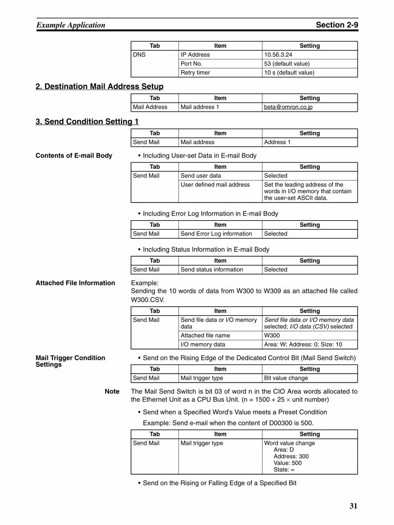
Example Application Section 2-9
2. Destination Mail Address Setup
3. Send Condition Setting 1
Contents of E-mail Body • Including User-set Data in E-mail Body
• Including Error Log Information in E-mail Body
• Including Status Information in E-mail Body
Attached File Information Example:Sending the 10 words of data from W300 to W309 as an attached file calledW300.CSV.
Mail Trigger Condition Settings
• Send on the Rising Edge of the Dedicated Control Bit (Mail Send Switch)
Note The Mail Send Switch is bit 03 of word n in the CIO Area words allocated tothe Ethernet Unit as a CPU Bus Unit. (n = 1500 + 25 × unit number)
• Send when a Specified Word's Value meets a Preset Condition
Example: Send e-mail when the content of D00300 is 500.
• Send on the Rising or Falling Edge of a Specified Bit
Tab Item Setting
DNS IP Address 10.56.3.24
Port No. 53 (default value)
Retry timer 10 s (default value)
Tab Item Setting
Mail Address Mail address 1 [email protected]
Tab Item Setting
Send Mail Mail address Address 1
Tab Item Setting
Send Mail Send user data Selected
User defined mail address Set the leading address of the words in I/O memory that contain the user-set ASCII data.
Tab Item Setting
Send Mail Send Error Log information Selected
Tab Item Setting
Send Mail Send status information Selected
Tab Item Setting
Send Mail Send file data or I/O memory data
Send file data or I/O memory data selected; I/O data (CSV) selected
Attached file name W300
I/O memory data Area: W; Address: 0; Size: 10
Tab Item Setting
Send Mail Mail trigger type Bit value change
Tab Item Setting
Send Mail Mail trigger type Word value changeArea: DAddress: 300Value: 500State: =
31
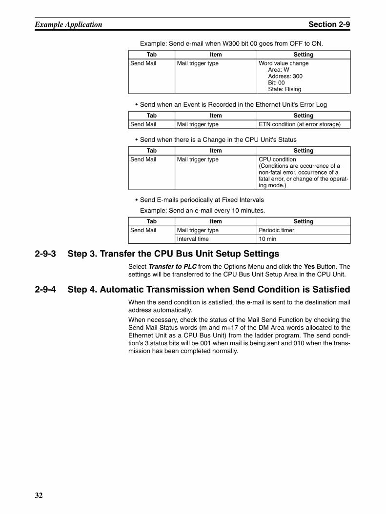
Example Application Section 2-9
Example: Send e-mail when W300 bit 00 goes from OFF to ON.
• Send when an Event is Recorded in the Ethernet Unit's Error Log
• Send when there is a Change in the CPU Unit's Status
• Send E-mails periodically at Fixed Intervals
Example: Send an e-mail every 10 minutes.
2-9-3 Step 3. Transfer the CPU Bus Unit Setup SettingsSelect Transfer to PLC from the Options Menu and click the Yes Button. Thesettings will be transferred to the CPU Bus Unit Setup Area in the CPU Unit.
2-9-4 Step 4. Automatic Transmission when Send Condition is SatisfiedWhen the send condition is satisfied, the e-mail is sent to the destination mailaddress automatically.
When necessary, check the status of the Mail Send Function by checking theSend Mail Status words (m and m+17 of the DM Area words allocated to theEthernet Unit as a CPU Bus Unit) from the ladder program. The send condi-tion's 3 status bits will be 001 when mail is being sent and 010 when the trans-mission has been completed normally.
Tab Item Setting
Send Mail Mail trigger type Word value changeArea: WAddress: 300Bit: 00State: Rising
Tab Item Setting
Send Mail Mail trigger type ETN condition (at error storage)
Tab Item Setting
Send Mail Mail trigger type CPU condition(Conditions are occurrence of a non-fatal error, occurrence of a fatal error, or change of the operat-ing mode.)
Tab Item Setting
Send Mail Mail trigger type Periodic timer
Interval time 10 min
32
SECTION 3Receive Mail Function
This section describes how to use the Ethernet Unit’s Mail Receive Function, including specifications, status details, I/Omemory data formats, file transfer timing, application examples, and troubleshooting information.
3-1 Mail Receive Function Overview . . . . . . . . . . . . . . . . . . . . . . . . . . . . . . . . . . 34
3-1-1 Introduction. . . . . . . . . . . . . . . . . . . . . . . . . . . . . . . . . . . . . . . . . . . . 34
3-1-2 Table of Remote Mail Commands . . . . . . . . . . . . . . . . . . . . . . . . . . 35
3-2 Mail Receive Function Specifications. . . . . . . . . . . . . . . . . . . . . . . . . . . . . . . 36
3-2-1 Function Specifications . . . . . . . . . . . . . . . . . . . . . . . . . . . . . . . . . . 36
3-3 Using the Mail Receive Function . . . . . . . . . . . . . . . . . . . . . . . . . . . . . . . . . . 38
3-3-1 Procedure . . . . . . . . . . . . . . . . . . . . . . . . . . . . . . . . . . . . . . . . . . . . . 38
3-3-2 Settings Required for the Mail Receive Function. . . . . . . . . . . . . . . 39
3-3-3 Receive Mail Tab . . . . . . . . . . . . . . . . . . . . . . . . . . . . . . . . . . . . . . . 40
3-4 Remote Mail Command Details . . . . . . . . . . . . . . . . . . . . . . . . . . . . . . . . . . . 42
3-4-1 Format. . . . . . . . . . . . . . . . . . . . . . . . . . . . . . . . . . . . . . . . . . . . . . . . 42
3-4-2 Response List . . . . . . . . . . . . . . . . . . . . . . . . . . . . . . . . . . . . . . . . . . 59
3-5 Mail Receive Function Status . . . . . . . . . . . . . . . . . . . . . . . . . . . . . . . . . . . . . 60
3-5-1 Accessing Memory/Receiving Mail Flag . . . . . . . . . . . . . . . . . . . . . 60
3-6 I/O Memory Data Formats . . . . . . . . . . . . . . . . . . . . . . . . . . . . . . . . . . . . . . . 60
3-7 Attached File Transfer Times . . . . . . . . . . . . . . . . . . . . . . . . . . . . . . . . . . . . . 62
3-8 Mail Receive Function Errors . . . . . . . . . . . . . . . . . . . . . . . . . . . . . . . . . . . . . 63
3-8-1 Identifying and Correcting Mail Receive Function Errors . . . . . . . . 63
3-8-2 Troubleshooting Mail Receive Errors with LED Indicators. . . . . . . 63
3-8-3 Error Log Codes Related to the Mail Receive Function. . . . . . . . . . 64
3-9 Example Application. . . . . . . . . . . . . . . . . . . . . . . . . . . . . . . . . . . . . . . . . . . . 65
3-9-1 Step 1. Create the I/O Table . . . . . . . . . . . . . . . . . . . . . . . . . . . . . . . 65
3-9-2 Step 2. Make the Unit Setup Settings from the CX-Programmer. . . 65
3-9-3 Step 3. Transfer the CPU Bus Unit Setup Settings. . . . . . . . . . . . . . 66
3-9-4 Step 4. Send Remote Mail Commands . . . . . . . . . . . . . . . . . . . . . . . 66
33
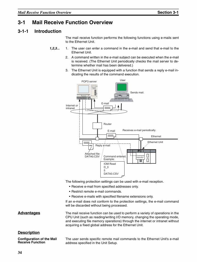
Mail Receive Function Overview Section 3-1
3-1 Mail Receive Function Overview
3-1-1 IntroductionThe mail receive function performs the following functions using e-mails sentto the Ethernet Unit.
1,2,3... 1. The user can enter a command in the e-mail and send that e-mail to theEthernet Unit.
2. A command written in the e-mail subject can be executed when the e-mailis received. (The Ethernet Unit periodically checks the mail server to de-termine whether mail has been delivered.)
3. The Ethernet Unit is equipped with a function that sends a reply e-mail in-dicating the results of the command execution.
The following protection settings can be used with e-mail reception.
• Receive e-mail from specified addresses only.
• Restrict remote e-mail commands.
• Receive e-mails with specified filename extensions only.
If an e-mail does not conform to the protection settings, the e-mail commandwill be discarded without being processed.
Advantages The mail receive function can be used to perform a variety of operations in theCPU Unit (such as reading/writing I/O memory, changing the operating mode,and executing file memory operations) through the internet or intranet withoutacquiring a fixed global address for the Ethernet Unit.
Description
Configuration of the Mail Receive Function
The user sends specific remote mail commands to the Ethernet Unit's e-mailaddress specified in the Unit Setup.
IOM Read
D_0
5
DATA0.CSV
Router
E-mail Receives e-mail periodically.
Ethernet
Ethernet Unit
Command entered.Example:
Reply e-mail
Attached file: DATA0.CSV
Internet or intranet
POP3 server User
Sends mail.
Command execution
34
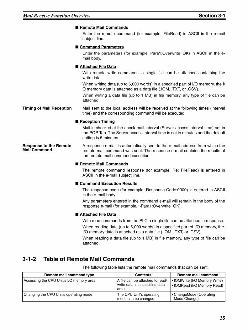
Mail Receive Function Overview Section 3-1
Remote Mail Commands
Enter the remote command (for example, FileRead) in ASCII in the e-mailsubject line.
Command Parameters
Enter the parameters (for example, Para1:Overwrite=OK) in ASCII in the e-mail body.
Attached File Data
With remote write commands, a single file can be attached containing thewrite data.
When writing data (up to 6,000 words) in a specified part of I/O memory, the I/O memory data is attached as a data file (.IOM, .TXT, or .CSV).
When writing a data file (up to 1 MB) in file memory, any type of file can beattached.
Timing of Mail Reception Mail sent to the local address will be received at the following times (intervaltime) and the corresponding command will be executed.
Reception Timing
Mail is checked at the check-mail interval (Server access interval time) set inthe POP Tab. The Server access interval time is set in minutes and the defaultsetting is 5 minutes.
Response to the Remote Mail Command
A response e-mail is automatically sent to the e-mail address from which theremote mail command was sent. The response e-mail contains the results ofthe remote mail command execution.
Remote Mail Commands
The remote command response (for example, Re: FileRead) is entered inASCII in the e-mail subject line.
Command Execution Results
The response code (for example, Response Code:0000) is entered in ASCIIin the e-mail body.
Any parameters entered in the command e-mail will remain in the body of theresponse e-mail (for example, >Para1:Overwrite=OK).
Attached File Data
With read commands from the PLC a single file can be attached in response.
When reading data (up to 6,000 words) in a specified part of I/O memory, the I/O memory data is attached as a data file (.IOM, .TXT, or .CSV).
When reading a data file (up to 1 MB) in file memory, any type of file can beattached.
3-1-2 Table of Remote Mail CommandsThe following table lists the remote mail commands that can be sent.
Remote mail command type Contents Remote mail command
Accessing the CPU Unit's I/O memory area A file can be attached to read/write data in a specified data area.
• IOMWrite (I/O Memory Write)• IOMRead (I/O Memory Read)
Changing the CPU Unit's operating mode The CPU Unit's operating mode can be changed.
• ChangeMode (Operating Mode Change)
35
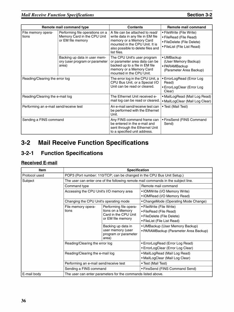
Mail Receive Function Specifications Section 3-2
3-2 Mail Receive Function Specifications
3-2-1 Function Specifications
Received E-mail
File memory opera-tions
Performing file operations on a Memory Card in the CPU Unit or EM file memory
A file can be attached to read/write data in any file in EM file memory or a Memory Card mounted in the CPU Unit. It is also possible to delete files and list files.
• FileWrite (File Write)• FileRead (File Read)• FileDelete (File Delete)• FileList (File List Read)
Backing up data in user mem-ory (user program or parameter area)
The CPU Unit's user program or parameter area data can be backed up to a file in EM file memory or a Memory Card mounted in the CPU Unit.
• UMBackup(User Memory Backup)
• PARAMBackup(Parameter Area Backup)
Reading/Clearing the error log The error log in the CPU Unit, a CPU Bus Unit, or a Special I/O Unit can be read or cleared.
• ErrorLogRead (Error Log Read)
• ErrorLogClear (Error Log Clear)
Reading/Clearing the e-mail log The Ethernet Unit received e-mail log can be read or cleared.
• MailLogRead (Mail Log Read)• MailLogClear (Mail Log Clear)
Performing an e-mail send/receive test An e-mail send/receive test can be performed with the Ethernet Unit.
• Test (Mail Test)
Sending a FINS command Any FINS command frame can be entered in the e-mail and sent through the Ethernet Unit to a specified unit address.
• FinsSend (FINS Command Send)
Remote mail command type Contents Remote mail command
Item Specification
Protocol used POP3 (Port number: 110/TCP; can be changed in the CPU Bus Unit Setup.)
Subject The user can enter one of the following remote mail commands in the subject line.
Command type Remote mail command
Accessing the CPU Unit's I/O memory area • IOMWrite (I/O Memory Write)• IOMRead (I/O Memory Read)
Changing the CPU Unit's operating mode • ChangeMode (Operating Mode Change)
File memory opera-tions
Performing file opera-tions on a Memory Card in the CPU Unit or EM file memory
• FileWrite (File Write)• FileRead (File Read)• FileDelete (File Delete)• FileList (File List Read)
Backing up data in user memory (user program or parameter area)
• UMBackup (User Memory Backup)• PARAMBackup (Parameter Area Backup)
Reading/Clearing the error log • ErrorLogRead (Error Log Read)• ErrorLogClear (Error Log Clear)
Reading/Clearing the e-mail log • MailLogRead (Mail Log Read)• MailLogClear (Mail Log Clear)
Performing an e-mail send/receive test • Test (Mail Test)
Sending a FINS command • FinsSend (FINS Command Send)
E-mail body The user can enter parameters for the commands listed above.
36
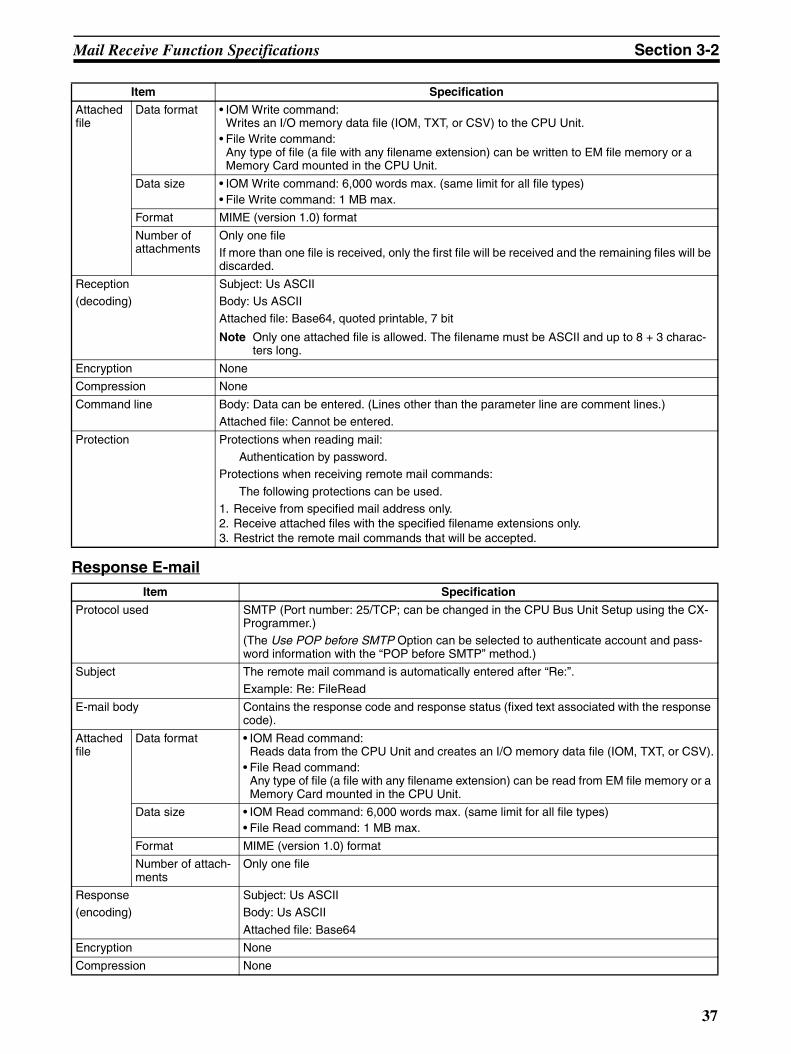
Mail Receive Function Specifications Section 3-2
Response E-mail
Attached file
Data format • IOM Write command:Writes an I/O memory data file (IOM, TXT, or CSV) to the CPU Unit.
• File Write command:Any type of file (a file with any filename extension) can be written to EM file memory or a Memory Card mounted in the CPU Unit.
Data size • IOM Write command: 6,000 words max. (same limit for all file types)• File Write command: 1 MB max.
Format MIME (version 1.0) format
Number of attachments
Only one fileIf more than one file is received, only the first file will be received and the remaining files will be discarded.
Reception(decoding)
Subject: Us ASCIIBody: Us ASCIIAttached file: Base64, quoted printable, 7 bit
Note Only one attached file is allowed. The filename must be ASCII and up to 8 + 3 charac-ters long.
Encryption None
Compression None
Command line Body: Data can be entered. (Lines other than the parameter line are comment lines.)Attached file: Cannot be entered.
Protection Protections when reading mail:Authentication by password.
Protections when receiving remote mail commands:
The following protections can be used.1. Receive from specified mail address only.2. Receive attached files with the specified filename extensions only.3. Restrict the remote mail commands that will be accepted.
Item Specification
Item Specification
Protocol used SMTP (Port number: 25/TCP; can be changed in the CPU Bus Unit Setup using the CX-Programmer.)(The Use POP before SMTP Option can be selected to authenticate account and pass-word information with the “POP before SMTP” method.)
Subject The remote mail command is automatically entered after “Re:”.Example: Re: FileRead
E-mail body Contains the response code and response status (fixed text associated with the response code).
Attached file
Data format • IOM Read command:Reads data from the CPU Unit and creates an I/O memory data file (IOM, TXT, or CSV).
• File Read command:Any type of file (a file with any filename extension) can be read from EM file memory or a Memory Card mounted in the CPU Unit.
Data size • IOM Read command: 6,000 words max. (same limit for all file types)• File Read command: 1 MB max.
Format MIME (version 1.0) format
Number of attach-ments
Only one file
Response(encoding)
Subject: Us ASCIIBody: Us ASCII
Attached file: Base64
Encryption None
Compression None
37
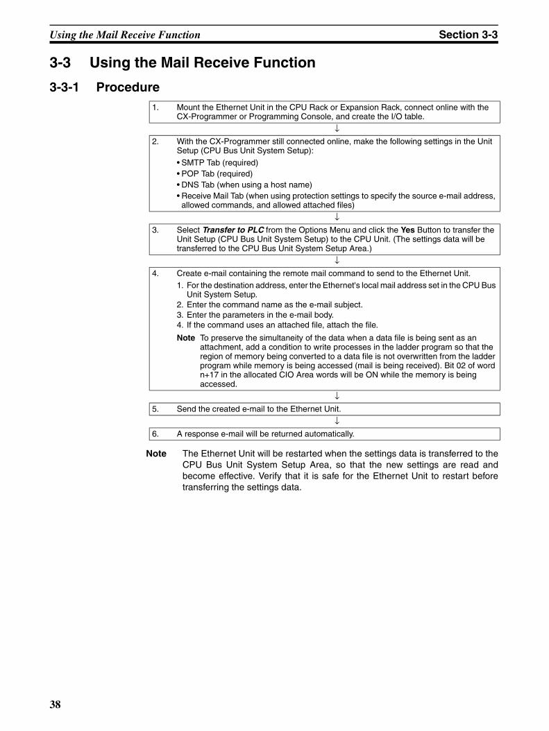
Using the Mail Receive Function Section 3-3
3-3 Using the Mail Receive Function
3-3-1 Procedure
Note The Ethernet Unit will be restarted when the settings data is transferred to theCPU Bus Unit System Setup Area, so that the new settings are read andbecome effective. Verify that it is safe for the Ethernet Unit to restart beforetransferring the settings data.
1. Mount the Ethernet Unit in the CPU Rack or Expansion Rack, connect online with the CX-Programmer or Programming Console, and create the I/O table.
↓2. With the CX-Programmer still connected online, make the following settings in the Unit
Setup (CPU Bus Unit System Setup):
• SMTP Tab (required)• POP Tab (required)• DNS Tab (when using a host name)• Receive Mail Tab (when using protection settings to specify the source e-mail address,
allowed commands, and allowed attached files)
↓3. Select Transfer to PLC from the Options Menu and click the Yes Button to transfer the
Unit Setup (CPU Bus Unit System Setup) to the CPU Unit. (The settings data will be transferred to the CPU Bus Unit System Setup Area.)
↓4. Create e-mail containing the remote mail command to send to the Ethernet Unit.
1. For the destination address, enter the Ethernet's local mail address set in the CPU Bus Unit System Setup.
2. Enter the command name as the e-mail subject.3. Enter the parameters in the e-mail body.4. If the command uses an attached file, attach the file.
Note To preserve the simultaneity of the data when a data file is being sent as an attachment, add a condition to write processes in the ladder program so that the region of memory being converted to a data file is not overwritten from the ladder program while memory is being accessed (mail is being received). Bit 02 of word n+17 in the allocated CIO Area words will be ON while the memory is being accessed.
↓5. Send the created e-mail to the Ethernet Unit.
↓6. A response e-mail will be returned automatically.
38
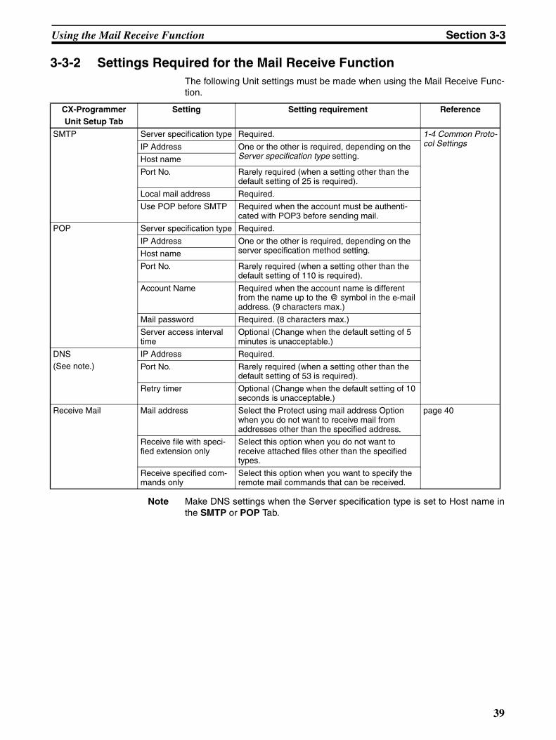
Using the Mail Receive Function Section 3-3
3-3-2 Settings Required for the Mail Receive FunctionThe following Unit settings must be made when using the Mail Receive Func-tion.
Note Make DNS settings when the Server specification type is set to Host name inthe SMTP or POP Tab.
CX-ProgrammerUnit Setup Tab
Setting Setting requirement Reference
SMTP Server specification type Required. 1-4 Common Proto-col SettingsIP Address One or the other is required, depending on the
Server specification type setting.Host name
Port No. Rarely required (when a setting other than the default setting of 25 is required).
Local mail address Required.
Use POP before SMTP Required when the account must be authenti-cated with POP3 before sending mail.
POP Server specification type Required.
IP Address One or the other is required, depending on the server specification method setting.Host name
Port No. Rarely required (when a setting other than the default setting of 110 is required).
Account Name Required when the account name is different from the name up to the @ symbol in the e-mail address. (9 characters max.)
Mail password Required. (8 characters max.)
Server access interval time
Optional (Change when the default setting of 5 minutes is unacceptable.)
DNS(See note.)
IP Address Required.
Port No. Rarely required (when a setting other than the default setting of 53 is required).
Retry timer Optional (Change when the default setting of 10 seconds is unacceptable.)
Receive Mail Mail address Select the Protect using mail address Option when you do not want to receive mail from addresses other than the specified address.
page 40
Receive file with speci-fied extension only
Select this option when you do not want to receive attached files other than the specified types.
Receive specified com-mands only
Select this option when you want to specify the remote mail commands that can be received.
39
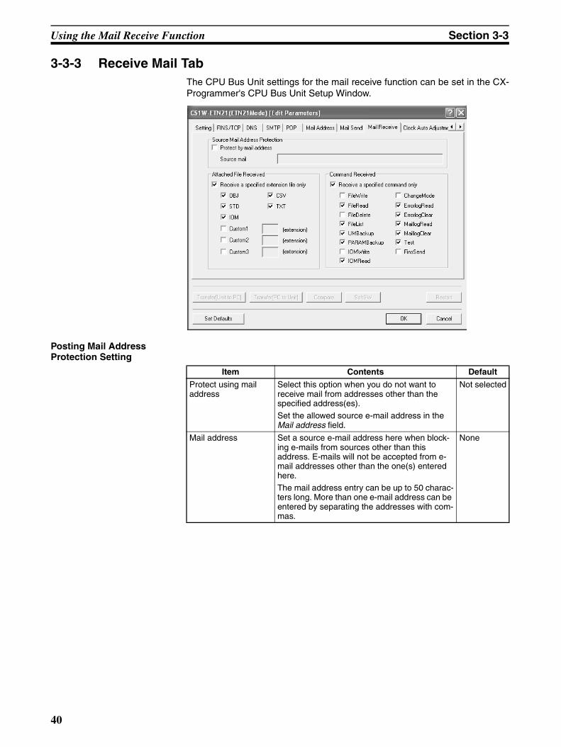
Using the Mail Receive Function Section 3-3
3-3-3 Receive Mail TabThe CPU Bus Unit settings for the mail receive function can be set in the CX-Programmer's CPU Bus Unit Setup Window.
Posting Mail Address Protection Setting
Item Contents Default
Protect using mail address
Select this option when you do not want to receive mail from addresses other than the specified address(es).Set the allowed source e-mail address in the Mail address field.
Not selected
Mail address Set a source e-mail address here when block-ing e-mails from sources other than this address. E-mails will not be accepted from e-mail addresses other than the one(s) entered here.The mail address entry can be up to 50 charac-ters long. More than one e-mail address can be entered by separating the addresses with com-mas.
None
40
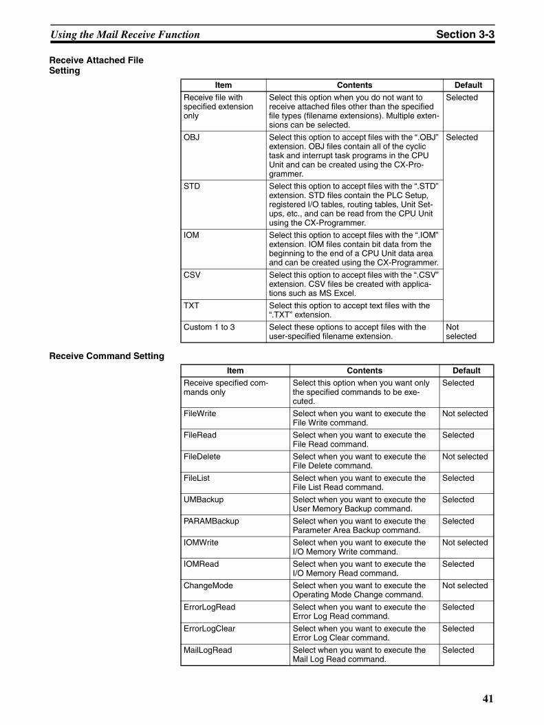
Using the Mail Receive Function Section 3-3
Receive Attached File Setting
Receive Command Setting
Item Contents Default
Receive file with specified extension only
Select this option when you do not want to receive attached files other than the specified file types (filename extensions). Multiple exten-sions can be selected.
Selected
OBJ Select this option to accept files with the “.OBJ” extension. OBJ files contain all of the cyclic task and interrupt task programs in the CPU Unit and can be created using the CX-Pro-grammer.
Selected
STD Select this option to accept files with the “.STD” extension. STD files contain the PLC Setup, registered I/O tables, routing tables, Unit Set-ups, etc., and can be read from the CPU Unit using the CX-Programmer.
IOM Select this option to accept files with the “.IOM” extension. IOM files contain bit data from the beginning to the end of a CPU Unit data area and can be created using the CX-Programmer.
CSV Select this option to accept files with the “.CSV” extension. CSV files be created with applica-tions such as MS Excel.
TXT Select this option to accept text files with the “.TXT” extension.
Custom 1 to 3 Select these options to accept files with the user-specified filename extension.
Not selected
Item Contents Default
Receive specified com-mands only
Select this option when you want only the specified commands to be exe-cuted.
Selected
FileWrite Select when you want to execute the File Write command.
Not selected
FileRead Select when you want to execute the File Read command.
Selected
FileDelete Select when you want to execute the File Delete command.
Not selected
FileList Select when you want to execute the File List Read command.
Selected
UMBackup Select when you want to execute the User Memory Backup command.
Selected
PARAMBackup Select when you want to execute the Parameter Area Backup command.
Selected
IOMWrite Select when you want to execute the I/O Memory Write command.
Not selected
IOMRead Select when you want to execute the I/O Memory Read command.
Selected
ChangeMode Select when you want to execute the Operating Mode Change command.
Not selected
ErrorLogRead Select when you want to execute the Error Log Read command.
Selected
ErrorLogClear Select when you want to execute the Error Log Clear command.
Selected
MailLogRead Select when you want to execute the Mail Log Read command.
Selected
41
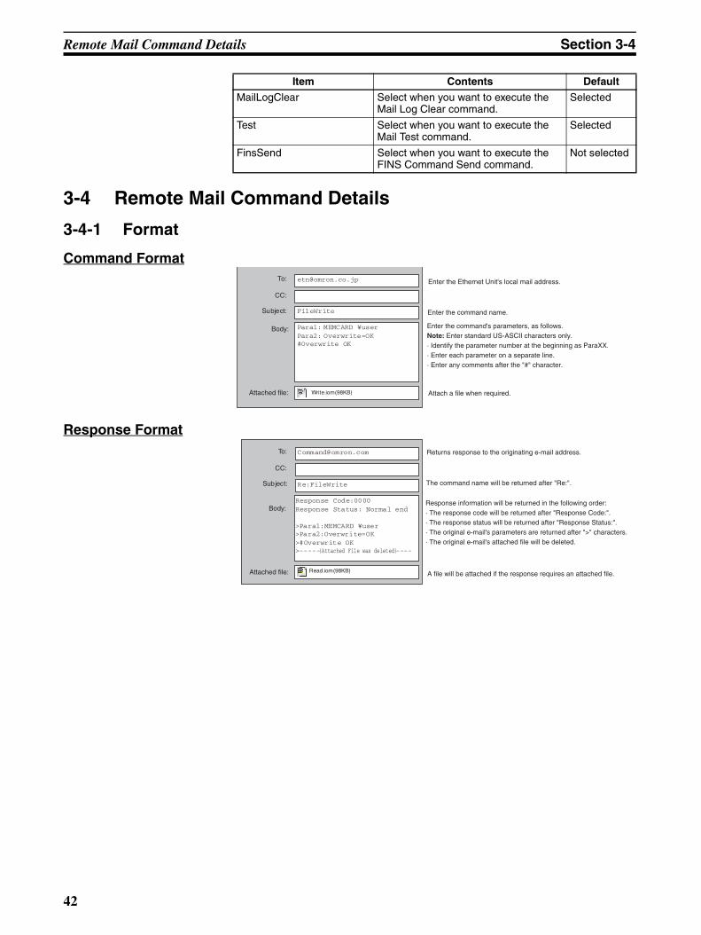
Remote Mail Command Details Section 3-4
3-4 Remote Mail Command Details
3-4-1 Format
Command Format
Response Format
MailLogClear Select when you want to execute the Mail Log Clear command.
Selected
Test Select when you want to execute the Mail Test command.
Selected
FinsSend Select when you want to execute the FINS Command Send command.
Not selected
Item Contents Default
To:
CC:
Subject:
FileWrite
Para1: MEMCARD ¥user Para2: Overwrite=OK#Overwrite OK
Write.iom(98KB)
Body:
Attached file:
Enter the Ethernet Unit's local mail address.
Enter the command name.
Enter the command's parameters, as follows.Note: Enter standard US-ASCII characters only.· Identify the parameter number at the beginning as ParaXX.· Enter each parameter on a separate line.· Enter any comments after the "#" character.
Attach a file when required.
To:
CC:
Subject:
Re:FileWrite
Response Code:0000 Response Status: Normal end >Para1:MEMCARD ¥user >Para2:Overwrite=OK >#Overwrite OK >-----(Attached File was deleted)----
Read.iom(98KB)
Body:
Attached file:
Returns response to the originating e-mail address.
The command name will be returned after "Re:".
Response information will be returned in the following order:· The response code will be returned after "Response Code:".· The response status will be returned after "Response Status:".· The original e-mail's parameters are returned after ">" characters.· The original e-mail's attached file will be deleted.
A file will be attached if the response requires an attached file.
42
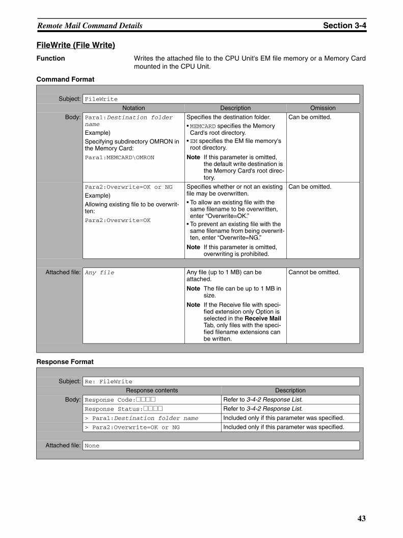
Remote Mail Command Details Section 3-4
FileWrite (File Write)
Function Writes the attached file to the CPU Unit's EM file memory or a Memory Cardmounted in the CPU Unit.
Command Format
Response Format
Subject: FileWrite
Notation Description Omission
Body: Para1:Destination folder name
Example)Specifying subdirectory OMRON in the Memory Card:
Para1:MEMCARD\OMRON
Specifies the destination folder.• MEMCARD specifies the Memory
Card's root directory.• EM specifies the EM file memory's
root directory.
Note If this parameter is omitted, the default write destination is the Memory Card's root direc-tory.
Can be omitted.
Para2:Overwrite=OK or NG
Example)Allowing existing file to be overwrit-ten:
Para2:Overwrite=OK
Specifies whether or not an existing file may be overwritten.• To allow an existing file with the
same filename to be overwritten, enter “Overwrite=OK.”
• To prevent an existing file with the same filename from being overwrit-ten, enter “Overwrite=NG.”
Note If this parameter is omitted, overwriting is prohibited.
Can be omitted.
Attached file: Any file Any file (up to 1 MB) can be attached.
Note The file can be up to 1 MB in size.
Note If the Receive file with speci-fied extension only Option is selected in the Receive Mail Tab, only files with the speci-fied filename extensions can be written.
Cannot be omitted.
Subject: Re: FileWrite
Response contents Description
Body: Response Code:@@@@ Refer to 3-4-2 Response List.
Response Status:@@@@ Refer to 3-4-2 Response List.
> Para1:Destination folder name Included only if this parameter was specified.
> Para2:Overwrite=OK or NG Included only if this parameter was specified.
Attached file: None
43
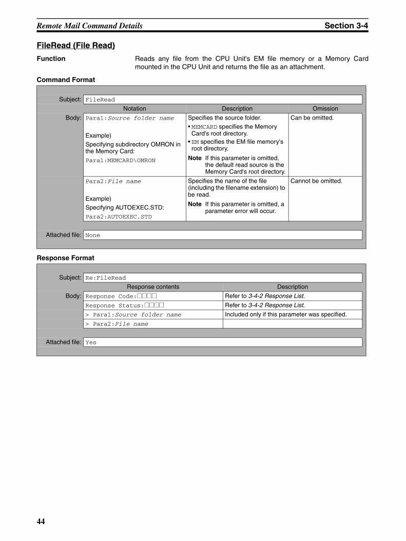
Remote Mail Command Details Section 3-4
FileRead (File Read)
Function Reads any file from the CPU Unit's EM file memory or a Memory Cardmounted in the CPU Unit and returns the file as an attachment.
Command Format
Response Format
Subject: FileRead
Notation Description Omission
Body: Para1:Source folder name
Example)Specifying subdirectory OMRON in the Memory Card:
Para1:MEMCARD\OMRON
Specifies the source folder.• MEMCARD specifies the Memory
Card's root directory.• EM specifies the EM file memory's
root directory.
Note If this parameter is omitted, the default read source is the Memory Card's root directory.
Can be omitted.
Para2:File name
Example)Specifying AUTOEXEC.STD:Para2:AUTOEXEC.STD
Specifies the name of the file (including the filename extension) to be read.
Note If this parameter is omitted, a parameter error will occur.
Cannot be omitted.
Attached file: None
Subject: Re:FileRead
Response contents Description
Body: Response Code:@@@@ Refer to 3-4-2 Response List.
Response Status:@@@@ Refer to 3-4-2 Response List.
> Para1:Source folder name Included only if this parameter was specified.
> Para2:File name
Attached file: Yes
44
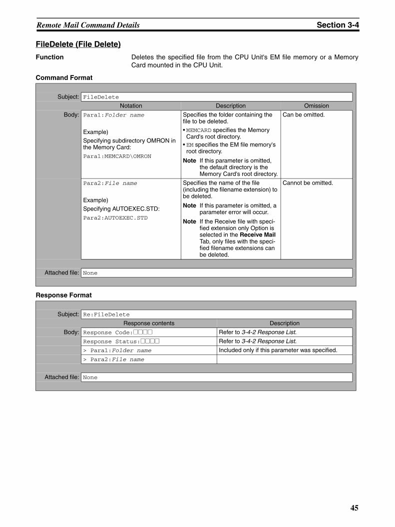
Remote Mail Command Details Section 3-4
FileDelete (File Delete)
Function Deletes the specified file from the CPU Unit's EM file memory or a MemoryCard mounted in the CPU Unit.
Command Format
Response Format
Subject: FileDelete
Notation Description Omission
Body: Para1:Folder name
Example)Specifying subdirectory OMRON in the Memory Card:
Para1:MEMCARD\OMRON
Specifies the folder containing the file to be deleted.
• MEMCARD specifies the Memory Card's root directory.
• EM specifies the EM file memory's root directory.
Note If this parameter is omitted, the default directory is the Memory Card's root directory.
Can be omitted.
Para2:File name
Example)Specifying AUTOEXEC.STD:
Para2:AUTOEXEC.STD
Specifies the name of the file (including the filename extension) to be deleted.
Note If this parameter is omitted, a parameter error will occur.
Note If the Receive file with speci-fied extension only Option is selected in the Receive Mail Tab, only files with the speci-fied filename extensions can be deleted.
Cannot be omitted.
Attached file: None
Subject: Re:FileDelete
Response contents Description
Body: Response Code:@@@@ Refer to 3-4-2 Response List.
Response Status:@@@@ Refer to 3-4-2 Response List.
> Para1:Folder name Included only if this parameter was specified.
> Para2:File name
Attached file: None
45
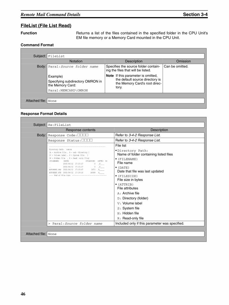
Remote Mail Command Details Section 3-4
FileList (File List Read)
Function Returns a list of the files contained in the specified folder in the CPU Unit'sEM file memory or a Memory Card mounted in the CPU Unit.
Command Format
Response Format Details
Subject: FileList
Notation Description Omission
Body: Para1:Source folder name
Example)Specifying subdirectory OMRON in the Memory Card:
Para1:MEMCARD\OMRON
Specifies the source folder contain-ing the files that will be listed.
Note If this parameter is omitted, the default source directory is the Memory Card's root direc-tory.
Can be omitted.
Attached file: None
Subject: Re:FileList
Response contents Description
Body: Response Code:@@@@ Refer to 3-4-2 Response List.
Response Status:@@@@ Refer to 3-4-2 Response List.
File list• Directory Path:
Name of folder containing listed files• (FILENAME)
File name• (DATE)
Date that file was last updated• (FILESIZE)
File size in bytes• (ATTRIB)
File attributesA: Archive fileD: Directory (folder)
V: Volume labelS: System fileH: Hidden file
R: Read-only file
> Para1:Source folder name Included only if this parameter was specified.
Attached file: None
--------------------------------------------------------
Directory Path: \omron
[A = Archive file , D = sub -Directory ]
[V = Volume label , S = System file ]
[H = Hidden file , R = Read -only file]
(FILENAME) (DATE) (FILESIZE) (ATTRI B)
. 2003/06/12 17:15:17 0 _D____
.. 2003/06/12 17:15:17 0 _D____
AUTOEXEC.OBJ 2003/06/12 17:19:07 2672 A_____
AUTOEXEC.STD 2003/06/12 17:19:10 16048 A_____
---- End of File List ----------------------------------
46
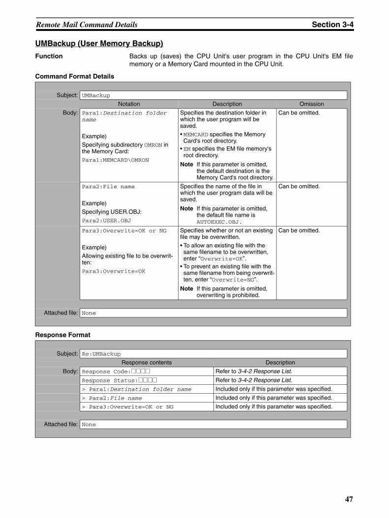
Remote Mail Command Details Section 3-4
UMBackup (User Memory Backup)
Function Backs up (saves) the CPU Unit's user program in the CPU Unit's EM filememory or a Memory Card mounted in the CPU Unit.
Command Format Details
Response Format
Subject: UMBackup
Notation Description Omission
Body: Para1:Destination folder name
Example)Specifying subdirectory OMRON in the Memory Card:Para1:MEMCARD\OMRON
Specifies the destination folder in which the user program will be saved.• MEMCARD specifies the Memory
Card's root directory.• EM specifies the EM file memory's
root directory.
Note If this parameter is omitted, the default destination is the Memory Card's root directory.
Can be omitted.
Para2:File name
Example)
Specifying USER.OBJ:Para2:USER.OBJ
Specifies the name of the file in which the user program data will be saved.
Note If this parameter is omitted, the default file name is AUTOEXEC.OBJ.
Can be omitted.
Para3:Overwrite=OK or NG
Example)Allowing existing file to be overwrit-ten:
Para3:Overwrite=OK
Specifies whether or not an existing file may be overwritten.
• To allow an existing file with the same filename to be overwritten, enter “Overwrite=OK”.
• To prevent an existing file with the same filename from being overwrit-ten, enter “Overwrite=NG”.
Note If this parameter is omitted, overwriting is prohibited.
Can be omitted.
Attached file: None
Subject: Re:UMBackup
Response contents Description
Body: Response Code:@@@@ Refer to 3-4-2 Response List.
Response Status:@@@@ Refer to 3-4-2 Response List.
> Para1:Destination folder name Included only if this parameter was specified.
> Para2:File name Included only if this parameter was specified.
> Para3:Overwrite=OK or NG Included only if this parameter was specified.
Attached file: None
47
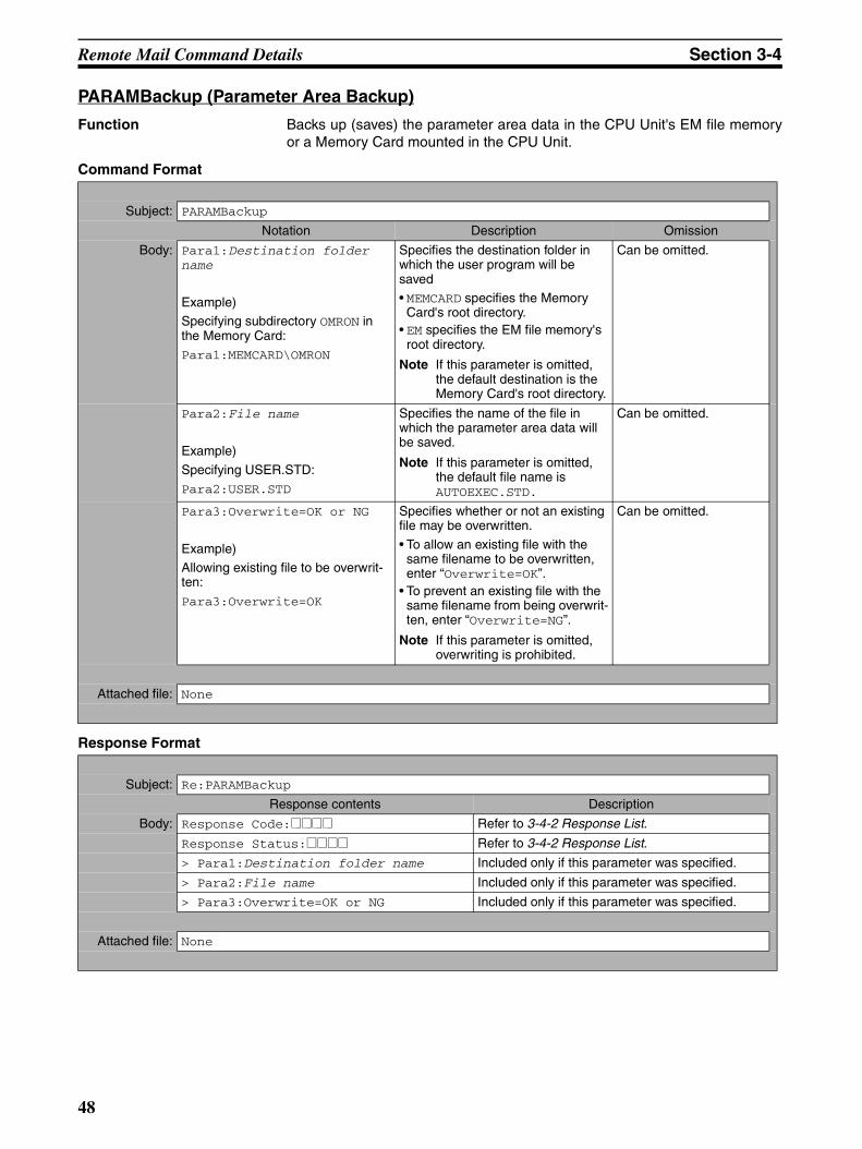
Remote Mail Command Details Section 3-4
PARAMBackup (Parameter Area Backup)
Function Backs up (saves) the parameter area data in the CPU Unit's EM file memoryor a Memory Card mounted in the CPU Unit.
Command Format
Response Format
Subject: PARAMBackup
Notation Description Omission
Body: Para1:Destination folder name
Example)Specifying subdirectory OMRON in the Memory Card:Para1:MEMCARD\OMRON
Specifies the destination folder in which the user program will be saved• MEMCARD specifies the Memory
Card's root directory.• EM specifies the EM file memory's
root directory.
Note If this parameter is omitted, the default destination is the Memory Card's root directory.
Can be omitted.
Para2:File name
Example)
Specifying USER.STD:Para2:USER.STD
Specifies the name of the file in which the parameter area data will be saved.
Note If this parameter is omitted, the default file name is AUTOEXEC.STD.
Can be omitted.
Para3:Overwrite=OK or NG
Example)Allowing existing file to be overwrit-ten:
Para3:Overwrite=OK
Specifies whether or not an existing file may be overwritten.
• To allow an existing file with the same filename to be overwritten, enter “Overwrite=OK”.
• To prevent an existing file with the same filename from being overwrit-ten, enter “Overwrite=NG”.
Note If this parameter is omitted, overwriting is prohibited.
Can be omitted.
Attached file: None
Subject: Re:PARAMBackup
Response contents Description
Body: Response Code:@@@@ Refer to 3-4-2 Response List.
Response Status:@@@@ Refer to 3-4-2 Response List.
> Para1:Destination folder name Included only if this parameter was specified.
> Para2:File name Included only if this parameter was specified.
> Para3:Overwrite=OK or NG Included only if this parameter was specified.
Attached file: None
48
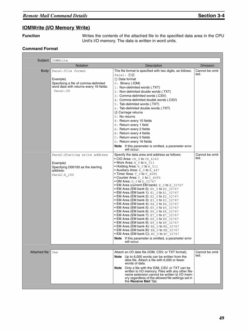
Remote Mail Command Details Section 3-4
IOMWrite (I/O Memory Write)
Function Writes the contents of the attached file to the specified data area in the CPUUnit's I/O memory. The data is written in word units.
Command Format
Subject: IOMWrite
Notation Description Omission
Body: Para1:File format
Example)Specifying a file of comma-delimited word data with returns every 16 fields: Para1:3D
The file format is specified with two digits, as follows:Para1: AB
A Data format0: Binary (.IOM)1: Non-delimited words (.TXT)2: Non-delimited double words (.TXT)3: Comma-delimited words (.CSV)4: Comma-delimited double words (.CSV)5: Tab-delimited words (.TXT)6: Tab-delimited double words (.TXT)B Carriage returns0: No returns8: Return every 10 fields9: Return every 1 fieldA: Return every 2 fieldsB: Return every 4 fieldsC: Return every 5 fieldsD: Return every 16 fieldsNote If this parameter is omitted, a parameter error
will occur.
Cannot be omit-ted.
Para2:Starting write address
Example)Specifying D00100 as the starting address:Para2:D_100
Specify the data area and address as follows:• CIO Area: CH_0 to CH_6143• Work Area: W_0 to W_511• Holding Area: H_0 to H_511• Auxiliary Area: A_0 to A_447• Timer Area: T_0 to T_4095• Counter Area: C_0 to C_4095• DM Area: D_0 to D_32767• EM Area (current EM bank): E_0 to E_32767• EM Area (EM bank 0): E0_0 to E0_32767• EM Area (EM bank 1): E1_0 to E1_32767• EM Area (EM bank 2): E2_0 to E2_32767• EM Area (EM bank 3): E3_0 to E3_32767• EM Area (EM bank 4): E4_0 to E4_32767• EM Area (EM bank 5): E5_0 to E5_32767• EM Area (EM bank 6): E6_0 to E6_32767• EM Area (EM bank 7): E7_0 to E7_32767• EM Area (EM bank 8): E8_0 to E8_32767• EM Area (EM bank 9): E9_0 to E9_32767• EM Area (EM bank A): EA_0 to EA_32767• EM Area (EM bank B): EB_0 to EB_32767• EM Area (EM bank C): EC_0 to EC_32767Note If this parameter is omitted, a parameter error
will occur.
Cannot be omit-ted.
Attached file: Yes Attach an I/O data file (IOM, CSV, or TXT format).Note Up to 6,000 words can be written from the
data file. Attach a file with 6,000 or fewer words of data.
Note Only a file with the IOM, CSV, or TXT can be written to I/O memory. Files with any other file-name extension cannot be written to I/O mem-ory regardless of the allowed file settings set in the Receive Mail Tab.
Cannot be omit-ted.
49
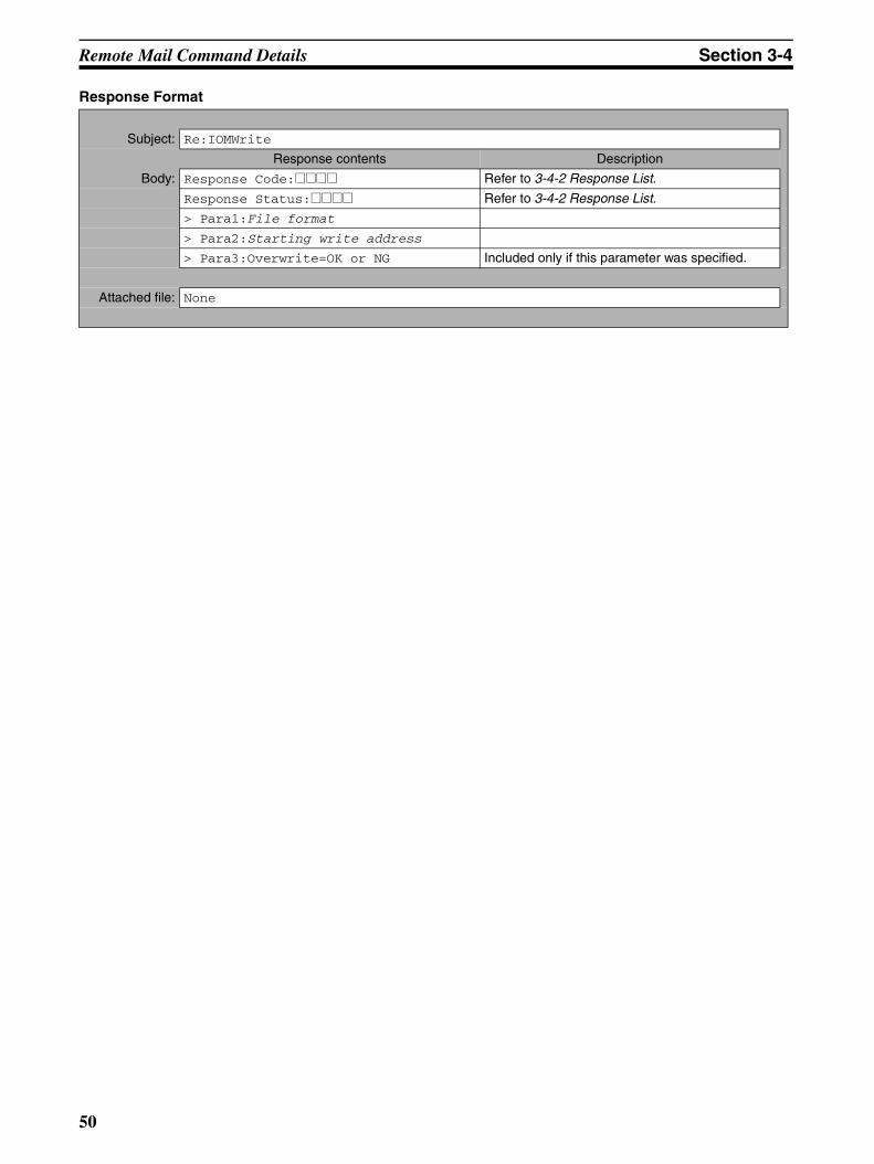
Remote Mail Command Details Section 3-4
Response Format
Subject: Re:IOMWrite
Response contents Description
Body: Response Code:@@@@ Refer to 3-4-2 Response List.
Response Status:@@@@ Refer to 3-4-2 Response List.
> Para1:File format
> Para2:Starting write address
> Para3:Overwrite=OK or NG Included only if this parameter was specified.
Attached file: None
50
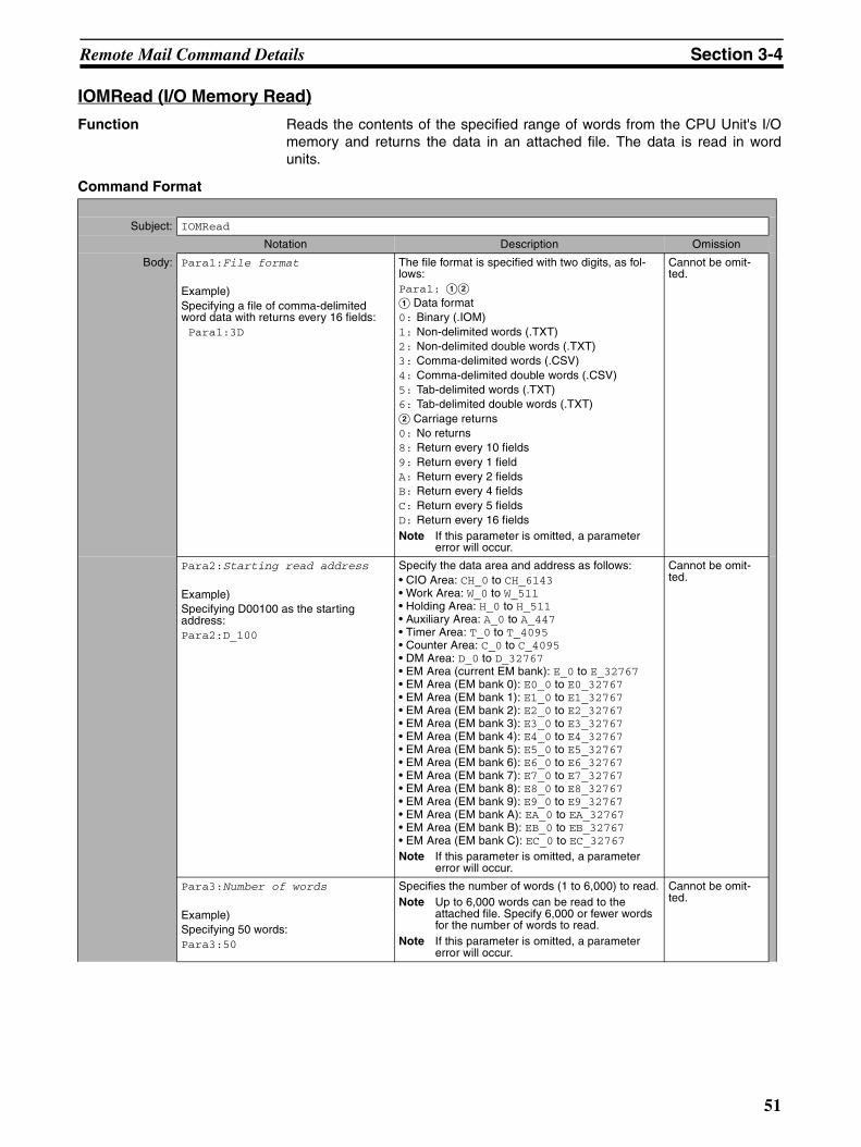
Remote Mail Command Details Section 3-4
IOMRead (I/O Memory Read)
Function Reads the contents of the specified range of words from the CPU Unit's I/Omemory and returns the data in an attached file. The data is read in wordunits.
Command Format
Subject: IOMRead
Notation Description Omission
Body: Para1:File format
Example)Specifying a file of comma-delimited word data with returns every 16 fields: Para1:3D
The file format is specified with two digits, as fol-lows:Para1: AB
A Data format0: Binary (.IOM)1: Non-delimited words (.TXT)2: Non-delimited double words (.TXT)3: Comma-delimited words (.CSV)4: Comma-delimited double words (.CSV)5: Tab-delimited words (.TXT)6: Tab-delimited double words (.TXT)B Carriage returns0: No returns8: Return every 10 fields9: Return every 1 fieldA: Return every 2 fieldsB: Return every 4 fieldsC: Return every 5 fieldsD: Return every 16 fieldsNote If this parameter is omitted, a parameter
error will occur.
Cannot be omit-ted.
Para2:Starting read address
Example)Specifying D00100 as the starting address:Para2:D_100
Specify the data area and address as follows:• CIO Area: CH_0 to CH_6143• Work Area: W_0 to W_511• Holding Area: H_0 to H_511• Auxiliary Area: A_0 to A_447• Timer Area: T_0 to T_4095• Counter Area: C_0 to C_4095• DM Area: D_0 to D_32767• EM Area (current EM bank): E_0 to E_32767• EM Area (EM bank 0): E0_0 to E0_32767• EM Area (EM bank 1): E1_0 to E1_32767• EM Area (EM bank 2): E2_0 to E2_32767• EM Area (EM bank 3): E3_0 to E3_32767• EM Area (EM bank 4): E4_0 to E4_32767• EM Area (EM bank 5): E5_0 to E5_32767• EM Area (EM bank 6): E6_0 to E6_32767• EM Area (EM bank 7): E7_0 to E7_32767• EM Area (EM bank 8): E8_0 to E8_32767• EM Area (EM bank 9): E9_0 to E9_32767• EM Area (EM bank A): EA_0 to EA_32767• EM Area (EM bank B): EB_0 to EB_32767• EM Area (EM bank C): EC_0 to EC_32767Note If this parameter is omitted, a parameter
error will occur.
Cannot be omit-ted.
Para3:Number of words
Example)Specifying 50 words:Para3:50
Specifies the number of words (1 to 6,000) to read.Note Up to 6,000 words can be read to the
attached file. Specify 6,000 or fewer words for the number of words to read.
Note If this parameter is omitted, a parameter error will occur.
Cannot be omit-ted.
51
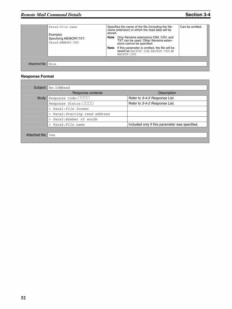
Remote Mail Command Details Section 3-4
Response Format
Para4:File name
Example)Specifying MEMORY.TXT:Para4:MEMORY.TXT
Specifies the name of the file (including the file-name extension) in which the read data will be stored.Note Only filename extensions IOM, CSV, and
TXT can be used. Other filename exten-sions cannot be specified.
Note If this parameter is omitted, the file will be saved as BACKUP.IOM, BACKUP.TXT, or BACKUP.CSV.
Can be omitted.
Attached file: None
Subject: Re:IOMRead
Response contents Description
Body: Response Code:@@@@ Refer to 3-4-2 Response List.
Response Status:@@@@ Refer to 3-4-2 Response List.
> Para1:File format
> Para2:Starting read address
> Para3:Number of words
> Para4:File name Included only if this parameter was specified.
Attached file: Yes
52
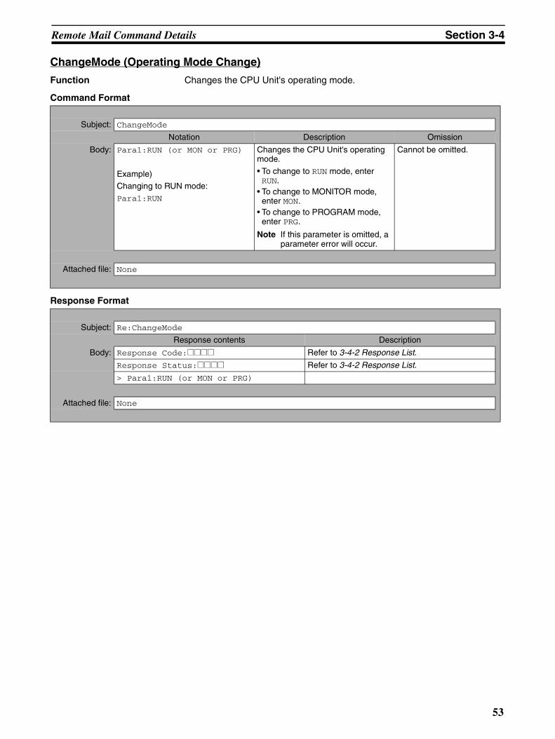
Remote Mail Command Details Section 3-4
ChangeMode (Operating Mode Change)
Function Changes the CPU Unit's operating mode.
Command Format
Response Format
Subject: ChangeMode
Notation Description Omission
Body: Para1:RUN (or MON or PRG)
Example)Changing to RUN mode:Para1:RUN
Changes the CPU Unit's operating mode.
• To change to RUN mode, enter RUN.
• To change to MONITOR mode, enter MON.
• To change to PROGRAM mode, enter PRG.
Note If this parameter is omitted, a parameter error will occur.
Cannot be omitted.
Attached file: None
Subject: Re:ChangeMode
Response contents Description
Body: Response Code:@@@@ Refer to 3-4-2 Response List.
Response Status:@@@@ Refer to 3-4-2 Response List.
> Para1:RUN (or MON or PRG)
Attached file: None
53

Remote Mail Command Details Section 3-4
ErrorLogRead (Error Log Read)
Function Reads the entire error log from the CPU Unit or a specified Special Unit (CPUBus Unit or Special I/O Unit).
Command Format
Response Format
Subject: ErrorLogRead
Notation Description Omission
Body: Para1:Unit address
Example)Specifying a CPU Bus Unit (unit number 0):
Para1:10
Specifies the unit address of the Unit from which the error log will be read.
Note If this parameter is omitted, a parameter error will occur.
Cannot be omitted.
Attached file: None
Subject: Re:ErrorLogRead
Response contents Description
Body: Response Code:@@@@ Refer to 3-4-2 Response List.
Response Status:@@@@ Refer to 3-4-2 Response List.
> Para1:Unit address
Attached file: None
54
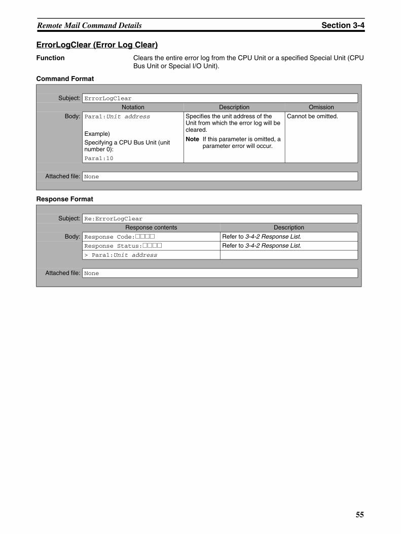
Remote Mail Command Details Section 3-4
ErrorLogClear (Error Log Clear)
Function Clears the entire error log from the CPU Unit or a specified Special Unit (CPUBus Unit or Special I/O Unit).
Command Format
Response Format
Subject: ErrorLogClear
Notation Description Omission
Body: Para1:Unit address
Example)Specifying a CPU Bus Unit (unit number 0):
Para1:10
Specifies the unit address of the Unit from which the error log will be cleared.
Note If this parameter is omitted, a parameter error will occur.
Cannot be omitted.
Attached file: None
Subject: Re:ErrorLogClear
Response contents Description
Body: Response Code:@@@@ Refer to 3-4-2 Response List.
Response Status:@@@@ Refer to 3-4-2 Response List.
> Para1:Unit address
Attached file: None
55
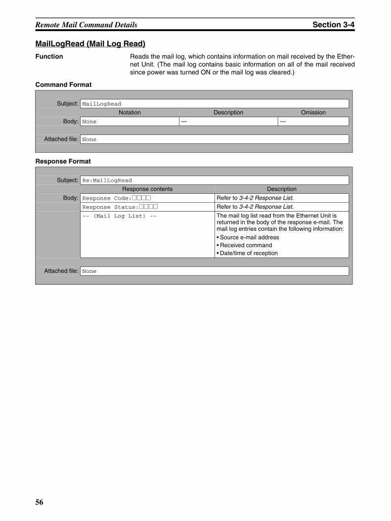
Remote Mail Command Details Section 3-4
MailLogRead (Mail Log Read)
Function Reads the mail log, which contains information on mail received by the Ether-net Unit. (The mail log contains basic information on all of the mail receivedsince power was turned ON or the mail log was cleared.)
Command Format
Response Format
Subject: MailLogRead
Notation Description Omission
Body: None --- ---
Attached file: None
Subject: Re:MailLogRead
Response contents Description
Body: Response Code:@@@@ Refer to 3-4-2 Response List.
Response Status:@@@@ Refer to 3-4-2 Response List.
-- (Mail Log List) -- The mail log list read from the Ethernet Unit is returned in the body of the response e-mail. The mail log entries contain the following information:• Source e-mail address• Received command• Date/time of reception
Attached file: None
56
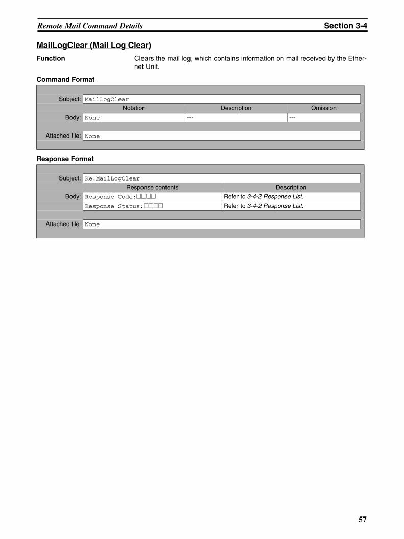
Remote Mail Command Details Section 3-4
MailLogClear (Mail Log Clear)
Function Clears the mail log, which contains information on mail received by the Ether-net Unit.
Command Format
Response Format
Subject: MailLogClear
Notation Description Omission
Body: None --- ---
Attached file: None
Subject: Re:MailLogClear
Response contents Description
Body: Response Code:@@@@ Refer to 3-4-2 Response List.
Response Status:@@@@ Refer to 3-4-2 Response List.
Attached file: None
57
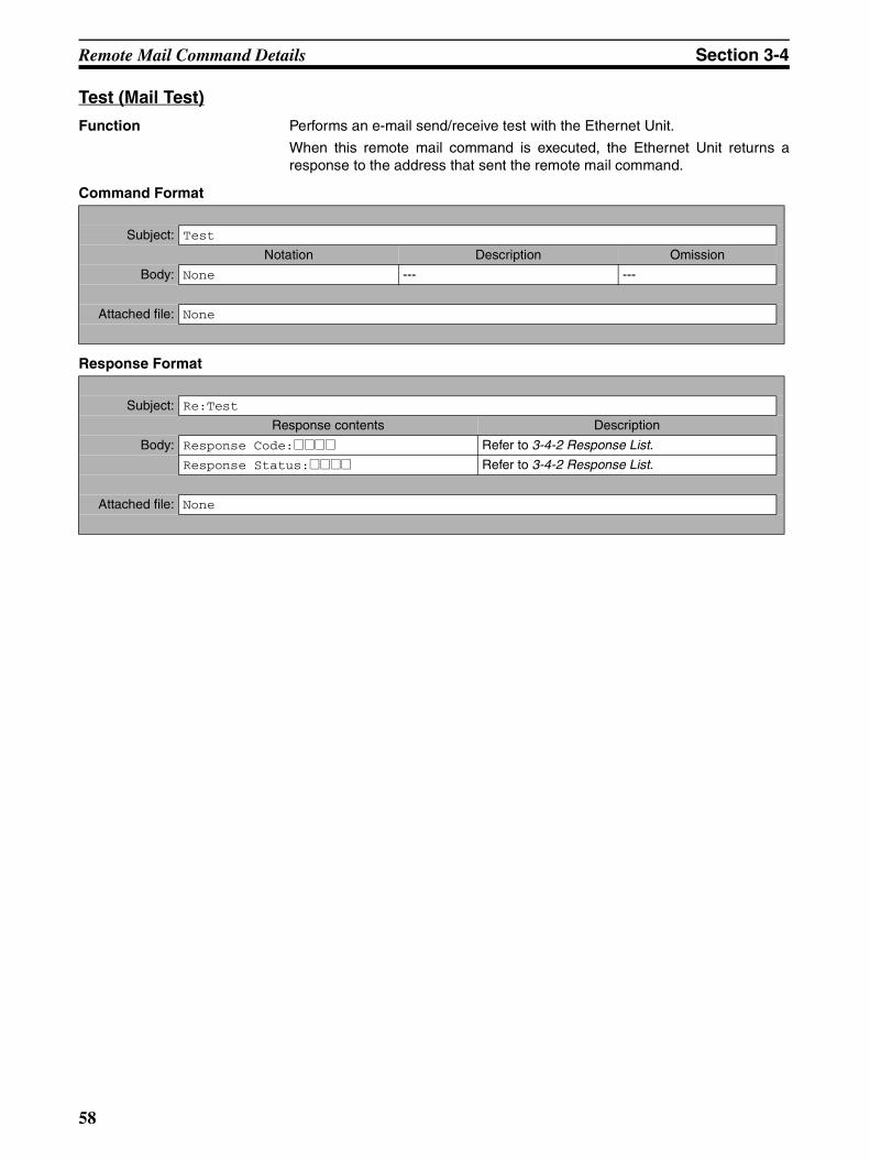
Remote Mail Command Details Section 3-4
Test (Mail Test)
Function Performs an e-mail send/receive test with the Ethernet Unit.
When this remote mail command is executed, the Ethernet Unit returns aresponse to the address that sent the remote mail command.
Command Format
Response Format
Subject: Test
Notation Description Omission
Body: None --- ---
Attached file: None
Subject: Re:Test
Response contents Description
Body: Response Code:@@@@ Refer to 3-4-2 Response List.
Response Status:@@@@ Refer to 3-4-2 Response List.
Attached file: None
58
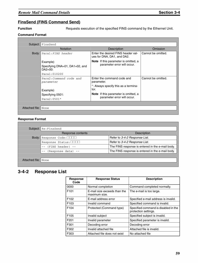
Remote Mail Command Details Section 3-4
FinsSend (FINS Command Send)
Function Requests execution of the specified FINS command by the Ethernet Unit.
Command Format
Response Format
3-4-2 Response List
Subject: FinsSend
Notation Description Omission
Body: Para1:FINS header
Example)Specifying DNA=01, DA1=02, and DA2=00:
Para1:010200
Enter the desired FINS header val-ues for DNA, DA1, and DA2.
Note If this parameter is omitted, a parameter error will occur.
Cannot be omitted.
Para2:Command code and parameter
Example)
Specifying 0501:Para2:0501*
Enter the command code and parameter.*: Always specify this as a termina-tor.
Note If this parameter is omitted, a parameter error will occur.
Cannot be omitted.
Attached file: None
Subject: Re:FinsSend
Response contents Description
Body: Response Code:@@@@ Refer to 3-4-2 Response List.
Response Status:@@@@ Refer to 3-4-2 Response List.
-- (FINS header) -- The FINS response is entered in the e-mail body.
-- (Response data) -- The FINS response is entered in the e-mail body.
Attached file: None
Response Code
Response Status Description
0000 Normal completion Command completed normally.
F101 E-mail size exceeds than the maximum size.
The e-mail is too large.
F102 E-mail address error Specified e-mail address is invalid.
F103 Invalid command Specified command is invalid.
F104 Protected (Command type) Specified command is disabled in the protection settings.
F105 Invalid subject Specified subject is invalid.
F201 Invalid parameter Specified parameter is invalid.
F301 Decoding error Decoding error
F302 Invalid attached file Attached file is invalid.
F303 Attached file does not exist No attached file
59
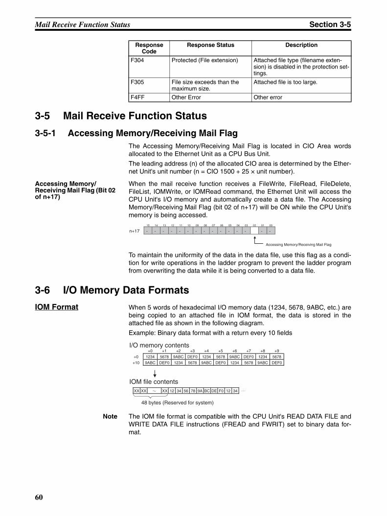
Mail Receive Function Status Section 3-5
3-5 Mail Receive Function Status
3-5-1 Accessing Memory/Receiving Mail FlagThe Accessing Memory/Receiving Mail Flag is located in CIO Area wordsallocated to the Ethernet Unit as a CPU Bus Unit.
The leading address (n) of the allocated CIO area is determined by the Ether-net Unit's unit number (n = CIO 1500 + 25 × unit number).
Accessing Memory/Receiving Mail Flag (Bit 02 of n+17)
When the mail receive function receives a FileWrite, FileRead, FileDelete,FileList, IOMWrite, or IOMRead command, the Ethernet Unit will access theCPU Unit's I/O memory and automatically create a data file. The AccessingMemory/Receiving Mail Flag (bit 02 of n+17) will be ON while the CPU Unit'smemory is being accessed.
To maintain the uniformity of the data in the data file, use this flag as a condi-tion for write operations in the ladder program to prevent the ladder programfrom overwriting the data while it is being converted to a data file.
3-6 I/O Memory Data Formats
IOM Format When 5 words of hexadecimal I/O memory data (1234, 5678, 9ABC, etc.) arebeing copied to an attached file in IOM format, the data is stored in theattached file as shown in the following diagram.
Example: Binary data format with a return every 10 fields
Note The IOM file format is compatible with the CPU Unit's READ DATA FILE andWRITE DATA FILE instructions (FREAD and FWRIT) set to binary data for-mat.
F304 Protected (File extension) Attached file type (filename exten-sion) is disabled in the protection set-tings.
F305 File size exceeds than the maximum size.
Attached file is too large.
F4FF Other Error Other error
Response Code
Response Status Description
Accessing Memory/Receiving Mail Flag
15 14 13 12 11 10 09 08 07 06 05 04 03 02 01 00
- - - - - - - - - - - - - -n+17 -
+0 +1 +2 +3 +4 +5 +6 +7 +8 +9
+0 1234 5678 9ABC DEF0 1234 5678 9ABC DEF0 1234 5678
+10 9ABC DEF0 1234 5678 9ABC DEF0 1234 5678 9ABC DEF0
XX XX XX 12 34 56 78 9A BC DE F0 12 34
48 bytes (Reserved for system)
IOM file contents
I/O memory contents
60
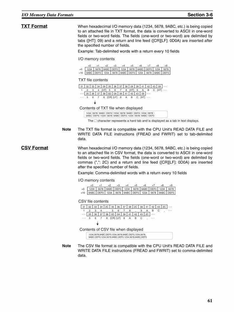
I/O Memory Data Formats Section 3-6
TXT Format When hexadecimal I/O memory data (1234, 5678, 9ABC, etc.) is being copiedto an attached file in TXT format, the data is converted to ASCII in one-wordfields or two-word fields. The fields (one-word or two-word) are delimited bytabs ([HT]: 09) and a return and line feed ([CR][LF]: 0D0A) are inserted afterthe specified number of fields.
Example: Tab-delimited words with a return every 10 fields
Note The TXT file format is compatible with the CPU Unit's READ DATA FILE andWRITE DATA FILE instructions (FREAD and FWRIT) set to tab-delimiteddata.
CSV Format When hexadecimal I/O memory data (1234, 5678, 9ABC, etc.) is being copiedto an attached file in CSV format, the data is converted to ASCII in one-wordfields or two-word fields. The fields (one-word or two-word) are delimited bycommas (",": 2C) and a return and line feed ([CR][LF]: 0D0A) are insertedafter the specified number of fields.
Example: Comma-delimited words with a return every 10 fields
Note The CSV file format is compatible with the CPU Unit's READ DATA FILE andWRITE DATA FILE instructions (FREAD and FWRIT) set to comma-delimiteddata.
+0 +1 +2 +3 +4 +5 +6 +7 +8 +9
+0 1234 5678 9ABC DEF0 1234 5678 9ABC DEF0 1234 5678
+10 9ABC DEF0 1234 5678 9ABC DEF0 1234 5678 9ABC DEF0
31 32 33 34 09 35 36 37 38 09 39 41 42 43 09
1 2 3 4 [HT] 5 6 7 8 [HT] 9 A B C [HT]
35 36 37 38 0D 0A 39 41 42 43 09
5 6 7 8 [CR] [LF] 9 A B C [HT]
1234@5678@9ABC@DEF0@1234@5678@9ABC@DEF0@1234@5678@ 9ABC@DEF0@1234@5678@9ABC@DEF0@1234@5678@9ABC@DEF0
The @ character represents a hard tab and is displayed as a tab in text displays.
I/O memory contents
TXT file contents
Contents of TXT file when displayed
1234,5678,9ABC,DEF0,1234,5678,9ABC,DEF0,1234,5678, 9ABC,DEF0,1234,5678,9ABC,DEF0,1234,5678,9ABC,DEF0
+0 +1 +2 +3 +4 +5 +6 +7 +8 +9
+0 1234 5678 9ABC DEF0 1234 5678 9ABC DEF0 1234 5678
+10 9ABC DEF0 1234 5678 9ABC DEF0 1234 5678 9ABC DEF0
31 32 33 34 2C 35 36 37 38 2C 39 41 42 43 2C
1 2 3 4 , 5 6 7 8 , 9 A B C ,
35 36 37 38 0D 0A 39 41 42 43 2C
5 6 7 8 [CR] [LF] 9 A B C ,
I/O memory contents
CSV file contents
Contents of CSV file when displayed
61
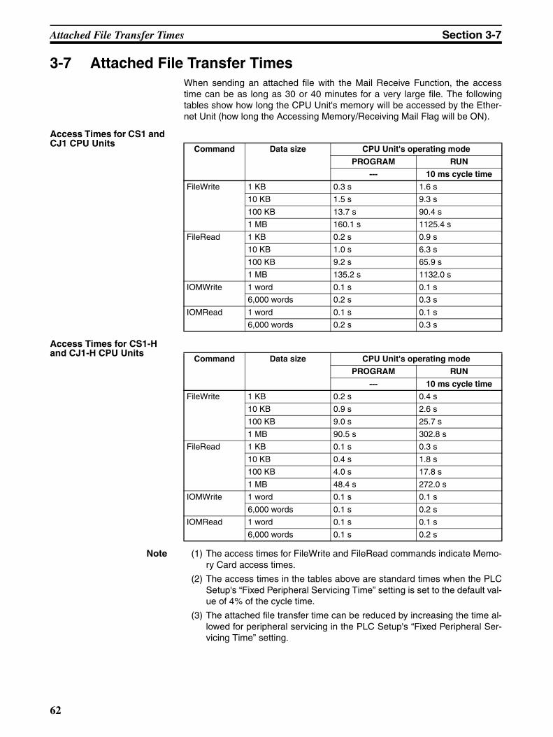
Attached File Transfer Times Section 3-7
3-7 Attached File Transfer TimesWhen sending an attached file with the Mail Receive Function, the accesstime can be as long as 30 or 40 minutes for a very large file. The followingtables show how long the CPU Unit's memory will be accessed by the Ether-net Unit (how long the Accessing Memory/Receiving Mail Flag will be ON).
Access Times for CS1 and CJ1 CPU Units
Access Times for CS1-H and CJ1-H CPU Units
Note (1) The access times for FileWrite and FileRead commands indicate Memo-ry Card access times.
(2) The access times in the tables above are standard times when the PLCSetup's “Fixed Peripheral Servicing Time” setting is set to the default val-ue of 4% of the cycle time.
(3) The attached file transfer time can be reduced by increasing the time al-lowed for peripheral servicing in the PLC Setup's “Fixed Peripheral Ser-vicing Time” setting.
Command Data size CPU Unit's operating mode
PROGRAM RUN
--- 10 ms cycle time
FileWrite 1 KB 0.3 s 1.6 s
10 KB 1.5 s 9.3 s
100 KB 13.7 s 90.4 s
1 MB 160.1 s 1125.4 s
FileRead 1 KB 0.2 s 0.9 s
10 KB 1.0 s 6.3 s
100 KB 9.2 s 65.9 s
1 MB 135.2 s 1132.0 s
IOMWrite 1 word 0.1 s 0.1 s
6,000 words 0.2 s 0.3 s
IOMRead 1 word 0.1 s 0.1 s
6,000 words 0.2 s 0.3 s
Command Data size CPU Unit's operating mode
PROGRAM RUN
--- 10 ms cycle time
FileWrite 1 KB 0.2 s 0.4 s
10 KB 0.9 s 2.6 s
100 KB 9.0 s 25.7 s
1 MB 90.5 s 302.8 s
FileRead 1 KB 0.1 s 0.3 s
10 KB 0.4 s 1.8 s
100 KB 4.0 s 17.8 s
1 MB 48.4 s 272.0 s
IOMWrite 1 word 0.1 s 0.1 s
6,000 words 0.1 s 0.2 s
IOMRead 1 word 0.1 s 0.1 s
6,000 words 0.1 s 0.2 s
62
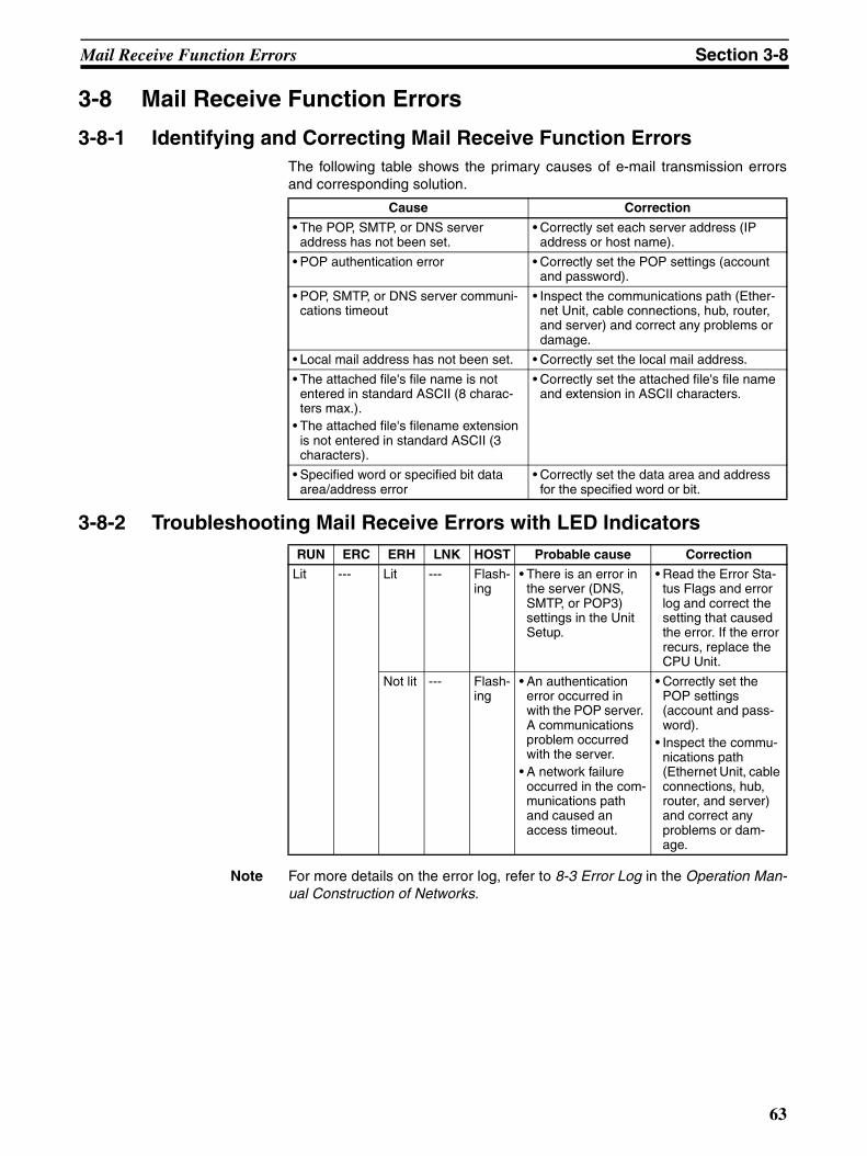
Mail Receive Function Errors Section 3-8
3-8 Mail Receive Function Errors
3-8-1 Identifying and Correcting Mail Receive Function ErrorsThe following table shows the primary causes of e-mail transmission errorsand corresponding solution.
3-8-2 Troubleshooting Mail Receive Errors with LED Indicators
Note For more details on the error log, refer to 8-3 Error Log in the Operation Man-ual Construction of Networks.
Cause Correction
• The POP, SMTP, or DNS server address has not been set.
• Correctly set each server address (IP address or host name).
• POP authentication error • Correctly set the POP settings (account and password).
• POP, SMTP, or DNS server communi-cations timeout
• Inspect the communications path (Ether-net Unit, cable connections, hub, router, and server) and correct any problems or damage.
• Local mail address has not been set. • Correctly set the local mail address.
• The attached file's file name is not entered in standard ASCII (8 charac-ters max.).
• The attached file's filename extension is not entered in standard ASCII (3 characters).
• Correctly set the attached file's file name and extension in ASCII characters.
• Specified word or specified bit data area/address error
• Correctly set the data area and address for the specified word or bit.
RUN ERC ERH LNK HOST Probable cause Correction
Lit --- Lit --- Flash-ing
• There is an error in the server (DNS, SMTP, or POP3) settings in the Unit Setup.
• Read the Error Sta-tus Flags and error log and correct the setting that caused the error. If the error recurs, replace the CPU Unit.
Not lit --- Flash-ing
• An authentication error occurred in with the POP server. A communications problem occurred with the server.
• A network failure occurred in the com-munications path and caused an access timeout.
• Correctly set the POP settings (account and pass-word).
• Inspect the commu-nications path (Ethernet Unit, cable connections, hub, router, and server) and correct any problems or dam-age.
63
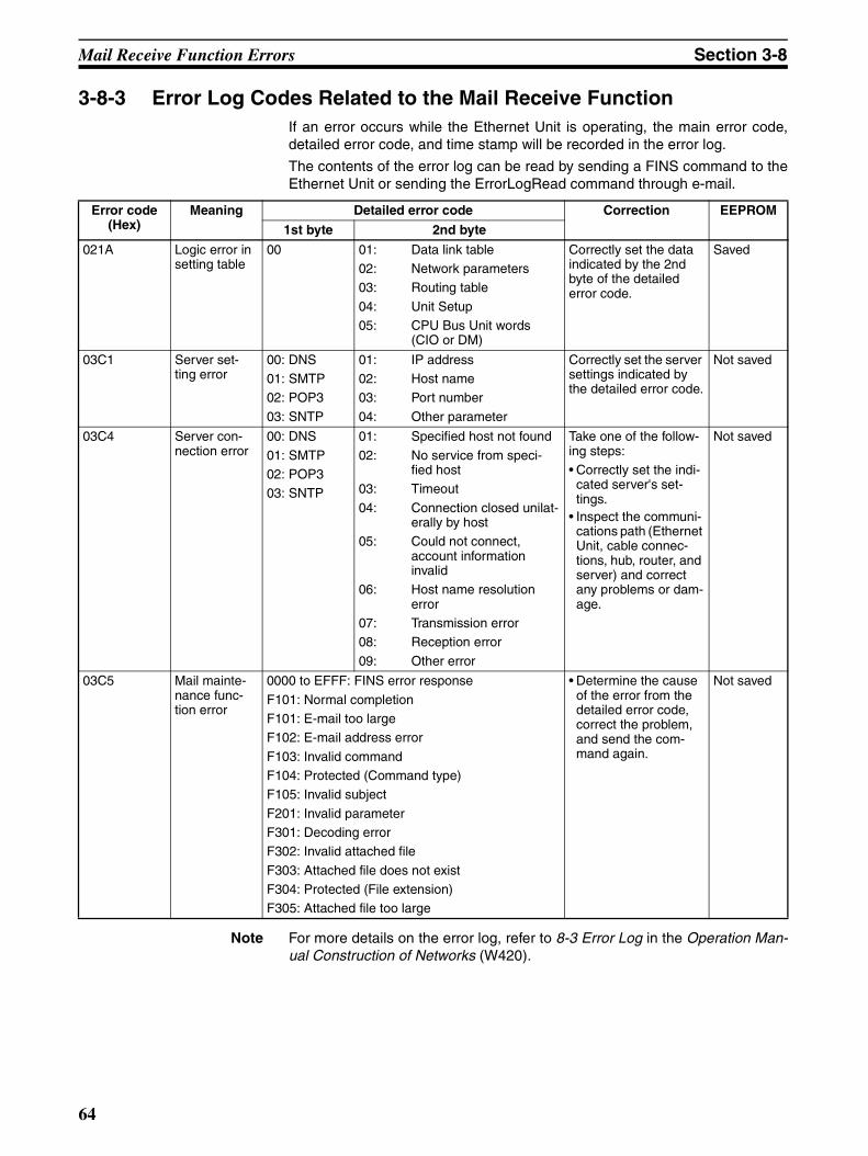
Mail Receive Function Errors Section 3-8
3-8-3 Error Log Codes Related to the Mail Receive FunctionIf an error occurs while the Ethernet Unit is operating, the main error code,detailed error code, and time stamp will be recorded in the error log.
The contents of the error log can be read by sending a FINS command to theEthernet Unit or sending the ErrorLogRead command through e-mail.
Note For more details on the error log, refer to 8-3 Error Log in the Operation Man-ual Construction of Networks (W420).
Error code (Hex)
Meaning Detailed error code Correction EEPROM
1st byte 2nd byte
021A Logic error in setting table
00 01: Data link table02: Network parameters03: Routing table
04: Unit Setup05: CPU Bus Unit words
(CIO or DM)
Correctly set the data indicated by the 2nd byte of the detailed error code.
Saved
03C1 Server set-ting error
00: DNS01: SMTP02: POP3
03: SNTP
01: IP address02: Host name03: Port number
04: Other parameter
Correctly set the server settings indicated by the detailed error code.
Not saved
03C4 Server con-nection error
00: DNS
01: SMTP02: POP303: SNTP
01: Specified host not found
02: No service from speci-fied host
03: Timeout
04: Connection closed unilat-erally by host
05: Could not connect, account information invalid
06: Host name resolution error
07: Transmission error08: Reception error
09: Other error
Take one of the follow-ing steps:• Correctly set the indi-
cated server's set-tings.
• Inspect the communi-cations path (Ethernet Unit, cable connec-tions, hub, router, and server) and correct any problems or dam-age.
Not saved
03C5 Mail mainte-nance func-tion error
0000 to EFFF: FINS error response
F101: Normal completionF101: E-mail too largeF102: E-mail address error
F103: Invalid commandF104: Protected (Command type) F105: Invalid subject
F201: Invalid parameterF301: Decoding errorF302: Invalid attached file
F303: Attached file does not existF304: Protected (File extension)F305: Attached file too large
• Determine the cause of the error from the detailed error code, correct the problem, and send the com-mand again.
Not saved
64
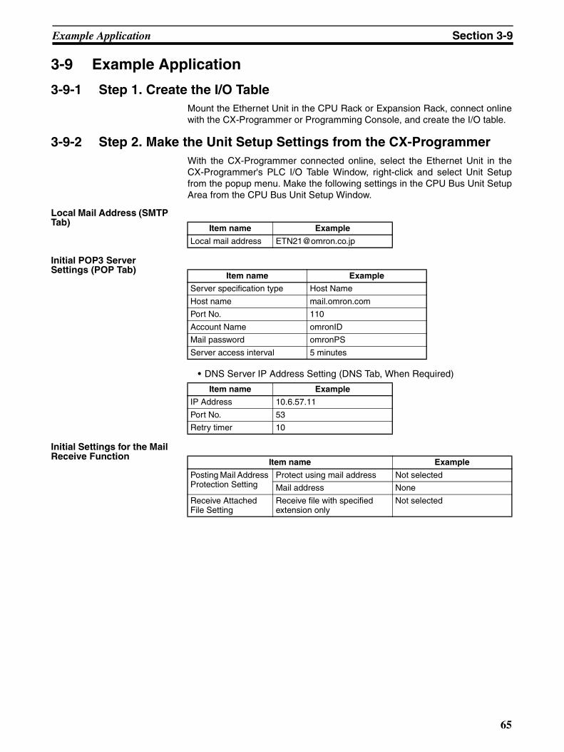
Example Application Section 3-9
3-9 Example Application
3-9-1 Step 1. Create the I/O TableMount the Ethernet Unit in the CPU Rack or Expansion Rack, connect onlinewith the CX-Programmer or Programming Console, and create the I/O table.
3-9-2 Step 2. Make the Unit Setup Settings from the CX-ProgrammerWith the CX-Programmer connected online, select the Ethernet Unit in theCX-Programmer's PLC I/O Table Window, right-click and select Unit Setupfrom the popup menu. Make the following settings in the CPU Bus Unit SetupArea from the CPU Bus Unit Setup Window.
Local Mail Address (SMTP Tab)
Initial POP3 Server Settings (POP Tab)
• DNS Server IP Address Setting (DNS Tab, When Required)
Initial Settings for the Mail Receive Function
Item name Example
Local mail address [email protected]
Item name Example
Server specification type Host Name
Host name mail.omron.com
Port No. 110
Account Name omronID
Mail password omronPS
Server access interval 5 minutes
Item name Example
IP Address 10.6.57.11
Port No. 53
Retry timer 10
Item name Example
Posting Mail Address Protection Setting
Protect using mail address Not selected
Mail address None
Receive Attached File Setting
Receive file with specified extension only
Not selected
65
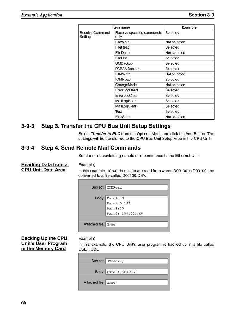
Example Application Section 3-9
3-9-3 Step 3. Transfer the CPU Bus Unit Setup SettingsSelect Transfer to PLC from the Options Menu and click the Yes Button. Thesettings will be transferred to the CPU Bus Unit Setup Area in the CPU Unit.
3-9-4 Step 4. Send Remote Mail CommandsSend e-mails containing remote mail commands to the Ethernet Unit.
Reading Data from a CPU Unit Data Area
Example)
In this example, 10 words of data are read from words D00100 to D00109 andconverted to a file called D00100.CSV.
Backing Up the CPU Unit's User Program in the Memory Card
Example)
In this example, the CPU Unit's user program is backed up in a file calledUSER.OBJ.
Receive Command Setting
Receive specified commands only
Selected
FileWrite Not selected
FileRead Selected
FileDelete Not selected
FileList Selected
UMBackup Selected
PARAMBackup Selected
IOMWrite Not selected
IOMRead Selected
ChangeMode Not selected
ErrorLogRead Selected
ErrorLogClear Selected
MailLogRead Selected
MailLogClear Selected
Test Selected
FinsSend Not selected
Item name Example
Subject: IOMRead
Body: Para1:38
Para2:D_100
Para3:10
Para4: D00100.CSV
Attached file: None
Subject: UMBackup
Body: Para2:USER.OBJ
Attached file: None
66
SECTION 4FTP Server
This section describes the functions provided by the FTP server.
4-1 Overview . . . . . . . . . . . . . . . . . . . . . . . . . . . . . . . . . . . . . . . . . . . . . . . . . . . . . 68
4-1-1 Specifications . . . . . . . . . . . . . . . . . . . . . . . . . . . . . . . . . . . . . . . . . . 68
4-2 FTP Server Function Details . . . . . . . . . . . . . . . . . . . . . . . . . . . . . . . . . . . . . . 69
4-2-1 File Types . . . . . . . . . . . . . . . . . . . . . . . . . . . . . . . . . . . . . . . . . . . . . 69
4-2-2 Connecting to the FTP Server. . . . . . . . . . . . . . . . . . . . . . . . . . . . . . 69
4-3 Using the FTP Server Function. . . . . . . . . . . . . . . . . . . . . . . . . . . . . . . . . . . . 70
4-3-1 Procedure . . . . . . . . . . . . . . . . . . . . . . . . . . . . . . . . . . . . . . . . . . . . . 70
4-3-2 List of Settings Required for the FTP Server Function . . . . . . . . . . 71
4-3-3 Setup Tab . . . . . . . . . . . . . . . . . . . . . . . . . . . . . . . . . . . . . . . . . . . . . 71
4-4 FTP Server Application Example . . . . . . . . . . . . . . . . . . . . . . . . . . . . . . . . . . 72
4-5 Using FTP Commands . . . . . . . . . . . . . . . . . . . . . . . . . . . . . . . . . . . . . . . . . . 73
4-5-1 Table of Commands . . . . . . . . . . . . . . . . . . . . . . . . . . . . . . . . . . . . . 73
4-5-2 Using the Commands . . . . . . . . . . . . . . . . . . . . . . . . . . . . . . . . . . . . 73
4-5-3 Error Messages and FTP Status . . . . . . . . . . . . . . . . . . . . . . . . . . . . 78
4-6 Checking FTP Status. . . . . . . . . . . . . . . . . . . . . . . . . . . . . . . . . . . . . . . . . . . . 79
4-6-1 FTP Status Flag. . . . . . . . . . . . . . . . . . . . . . . . . . . . . . . . . . . . . . . . . 79
4-7 Using File Memory . . . . . . . . . . . . . . . . . . . . . . . . . . . . . . . . . . . . . . . . . . . . . 80
4-7-1 File Memory . . . . . . . . . . . . . . . . . . . . . . . . . . . . . . . . . . . . . . . . . . . 80
4-7-2 File Types . . . . . . . . . . . . . . . . . . . . . . . . . . . . . . . . . . . . . . . . . . . . . 80
4-7-3 Initializing File Memory. . . . . . . . . . . . . . . . . . . . . . . . . . . . . . . . . . 82
4-7-4 I/O Memory Data Format . . . . . . . . . . . . . . . . . . . . . . . . . . . . . . . . . 82
4-8 FTP File Transfer Time. . . . . . . . . . . . . . . . . . . . . . . . . . . . . . . . . . . . . . . . . . 85
4-9 UNIX Application Example . . . . . . . . . . . . . . . . . . . . . . . . . . . . . . . . . . . . . . 86
67
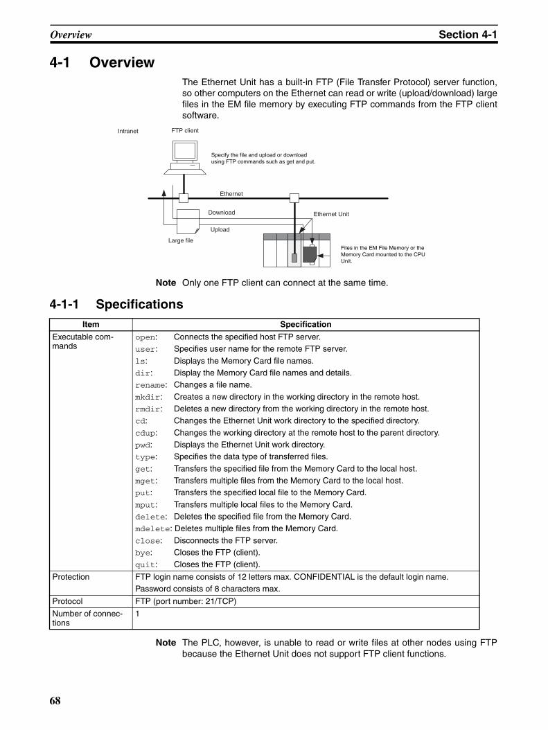
Overview Section 4-1
4-1 OverviewThe Ethernet Unit has a built-in FTP (File Transfer Protocol) server function,so other computers on the Ethernet can read or write (upload/download) largefiles in the EM file memory by executing FTP commands from the FTP clientsoftware.
Note Only one FTP client can connect at the same time.
4-1-1 Specifications
Note The PLC, however, is unable to read or write files at other nodes using FTPbecause the Ethernet Unit does not support FTP client functions.
Item Specification
Executable com-mands
open: Connects the specified host FTP server.user: Specifies user name for the remote FTP server.
ls: Displays the Memory Card file names.dir: Display the Memory Card file names and details.rename: Changes a file name.
mkdir: Creates a new directory in the working directory in the remote host.rmdir: Deletes a new directory from the working directory in the remote host.cd: Changes the Ethernet Unit work directory to the specified directory.
cdup: Changes the working directory at the remote host to the parent directory.pwd: Displays the Ethernet Unit work directory. type: Specifies the data type of transferred files.
get: Transfers the specified file from the Memory Card to the local host.mget: Transfers multiple files from the Memory Card to the local host.put: Transfers the specified local file to the Memory Card.
mput: Transfers multiple local files to the Memory Card.delete: Deletes the specified file from the Memory Card.mdelete: Deletes multiple files from the Memory Card.
close: Disconnects the FTP server.bye: Closes the FTP (client).quit: Closes the FTP (client).
Protection FTP login name consists of 12 letters max. CONFIDENTIAL is the default login name.Password consists of 8 characters max.
Protocol FTP (port number: 21/TCP)
Number of connec-tions
1
Ethernet Unit
Ethernet
FTP client Intranet
Large file
Upload
Download
Specify the file and upload or download using FTP commands such as get and put.
Files in the EM File Memory or the Memory Card mounted to the CPU Unit.
68
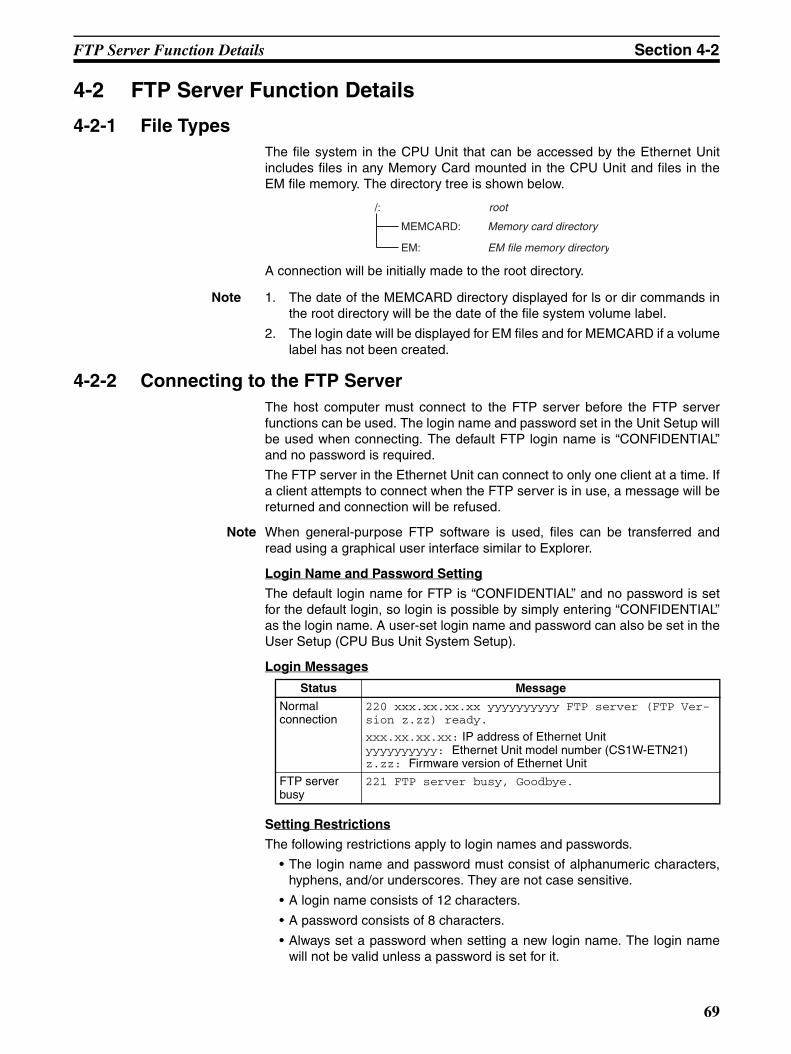
FTP Server Function Details Section 4-2
4-2 FTP Server Function Details
4-2-1 File TypesThe file system in the CPU Unit that can be accessed by the Ethernet Unitincludes files in any Memory Card mounted in the CPU Unit and files in theEM file memory. The directory tree is shown below.
A connection will be initially made to the root directory.
Note 1. The date of the MEMCARD directory displayed for ls or dir commands inthe root directory will be the date of the file system volume label.
2. The login date will be displayed for EM files and for MEMCARD if a volumelabel has not been created.
4-2-2 Connecting to the FTP ServerThe host computer must connect to the FTP server before the FTP serverfunctions can be used. The login name and password set in the Unit Setup willbe used when connecting. The default FTP login name is “CONFIDENTIAL”and no password is required.
The FTP server in the Ethernet Unit can connect to only one client at a time. Ifa client attempts to connect when the FTP server is in use, a message will bereturned and connection will be refused.
Note When general-purpose FTP software is used, files can be transferred andread using a graphical user interface similar to Explorer.
Login Name and Password Setting
The default login name for FTP is “CONFIDENTIAL” and no password is setfor the default login, so login is possible by simply entering “CONFIDENTIAL”as the login name. A user-set login name and password can also be set in theUser Setup (CPU Bus Unit System Setup).
Login Messages
Setting Restrictions
The following restrictions apply to login names and passwords.
• The login name and password must consist of alphanumeric characters,hyphens, and/or underscores. They are not case sensitive.
• A login name consists of 12 characters.
• A password consists of 8 characters.
• Always set a password when setting a new login name. The login namewill not be valid unless a password is set for it.
/: root
MEMCARD: Memory card directory
EM: EM file memory directory
Status Message
Normalconnection
220 xxx.xx.xx.xx yyyyyyyyyy FTP server (FTP Ver-sion z.zz) ready.
xxx.xx.xx.xx: IP address of Ethernet Unityyyyyyyyyy: Ethernet Unit model number (CS1W-ETN21)z.zz: Firmware version of Ethernet Unit
FTP server busy
221 FTP server busy, Goodbye.
69
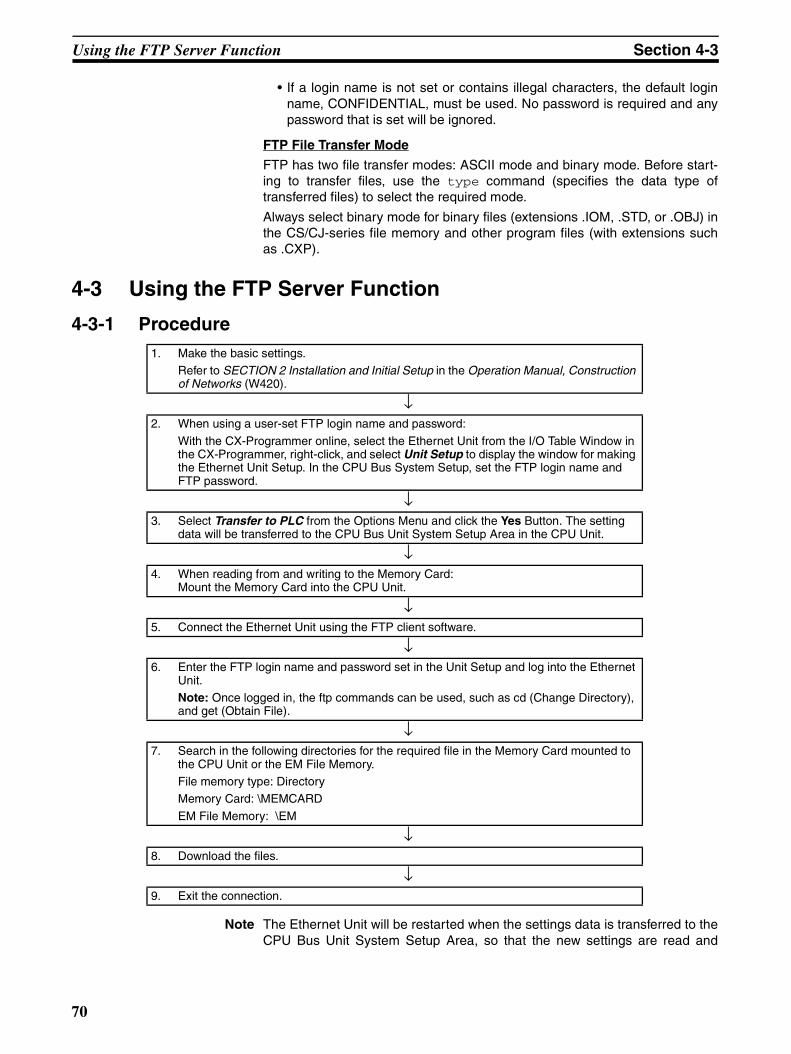
Using the FTP Server Function Section 4-3
• If a login name is not set or contains illegal characters, the default loginname, CONFIDENTIAL, must be used. No password is required and anypassword that is set will be ignored.
FTP File Transfer Mode
FTP has two file transfer modes: ASCII mode and binary mode. Before start-ing to transfer files, use the type command (specifies the data type oftransferred files) to select the required mode.
Always select binary mode for binary files (extensions .IOM, .STD, or .OBJ) inthe CS/CJ-series file memory and other program files (with extensions suchas .CXP).
4-3 Using the FTP Server Function
4-3-1 Procedure
Note The Ethernet Unit will be restarted when the settings data is transferred to theCPU Bus Unit System Setup Area, so that the new settings are read and
1. Make the basic settings.Refer to SECTION 2 Installation and Initial Setup in the Operation Manual, Construction of Networks (W420).
↓2. When using a user-set FTP login name and password:
With the CX-Programmer online, select the Ethernet Unit from the I/O Table Window in the CX-Programmer, right-click, and select Unit Setup to display the window for making the Ethernet Unit Setup. In the CPU Bus System Setup, set the FTP login name and FTP password.
↓3. Select Transfer to PLC from the Options Menu and click the Yes Button. The setting
data will be transferred to the CPU Bus Unit System Setup Area in the CPU Unit.
↓4. When reading from and writing to the Memory Card:
Mount the Memory Card into the CPU Unit.
↓5. Connect the Ethernet Unit using the FTP client software.
↓6. Enter the FTP login name and password set in the Unit Setup and log into the Ethernet
Unit.Note: Once logged in, the ftp commands can be used, such as cd (Change Directory), and get (Obtain File).
↓7. Search in the following directories for the required file in the Memory Card mounted to
the CPU Unit or the EM File Memory.File memory type: DirectoryMemory Card: \MEMCARD
EM File Memory: \EM
↓8. Download the files.
↓9. Exit the connection.
70
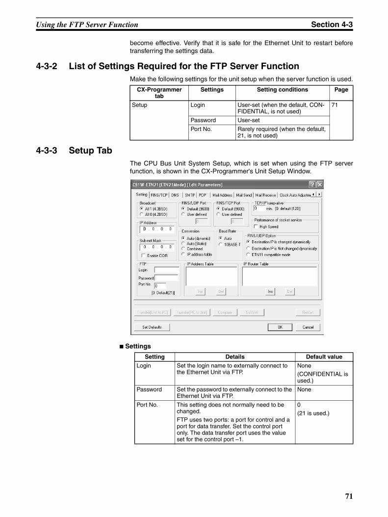
Using the FTP Server Function Section 4-3
become effective. Verify that it is safe for the Ethernet Unit to restart beforetransferring the settings data.
4-3-2 List of Settings Required for the FTP Server FunctionMake the following settings for the unit setup when the server function is used.
4-3-3 Setup TabThe CPU Bus Unit System Setup, which is set when using the FTP serverfunction, is shown in the CX-Programmer's Unit Setup Window.
Settings
CX-Programmer tab
Settings Setting conditions Page
Setup Login User-set (when the default, CON-FIDENTIAL, is not used)
71
Password User-set
Port No. Rarely required (when the default, 21, is not used)
Setting Details Default value
Login Set the login name to externally connect to the Ethernet Unit via FTP.
None(CONFIDENTIAL is used.)
Password Set the password to externally connect to the Ethernet Unit via FTP.
None
Port No. This setting does not normally need to be changed.FTP uses two ports: a port for control and a port for data transfer. Set the control port only. The data transfer port uses the value set for the control port –1.
0(21 is used.)
71
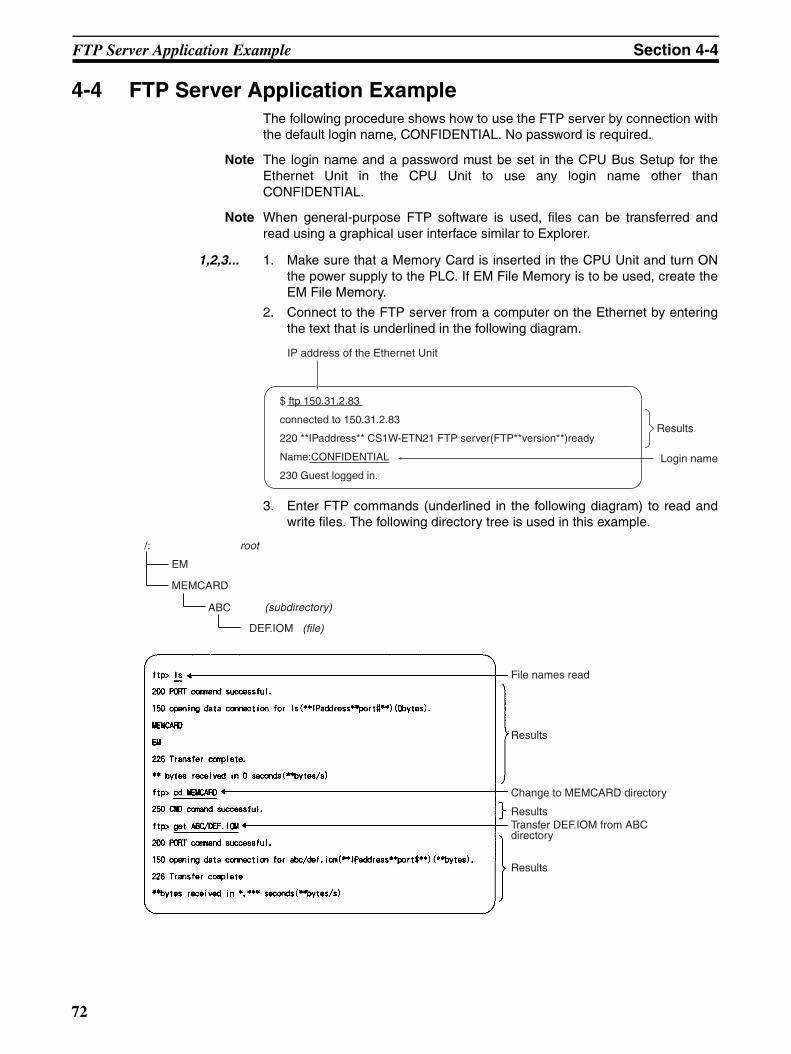
FTP Server Application Example Section 4-4
4-4 FTP Server Application ExampleThe following procedure shows how to use the FTP server by connection withthe default login name, CONFIDENTIAL. No password is required.
Note The login name and a password must be set in the CPU Bus Setup for theEthernet Unit in the CPU Unit to use any login name other thanCONFIDENTIAL.
Note When general-purpose FTP software is used, files can be transferred andread using a graphical user interface similar to Explorer.
1,2,3... 1. Make sure that a Memory Card is inserted in the CPU Unit and turn ONthe power supply to the PLC. If EM File Memory is to be used, create theEM File Memory.
2. Connect to the FTP server from a computer on the Ethernet by enteringthe text that is underlined in the following diagram.
3. Enter FTP commands (underlined in the following diagram) to read andwrite files. The following directory tree is used in this example.
IP address of the Ethernet Unit
Results
Login name
$ ftp 150.31.2.83
connected to 150.31.2.83
220 **IPaddress** CS1W-ETN21 FTP server(FTP**version**)ready
Name:CONFIDENTIAL
230 Guest logged in.
File names read
Results
Change to MEMCARD directory
ResultsTransfer DEF.IOM from ABC directory
Results
/: root
EM
MEMCARD
ABC
DEF.IOM (file)
(subdirectory)
72
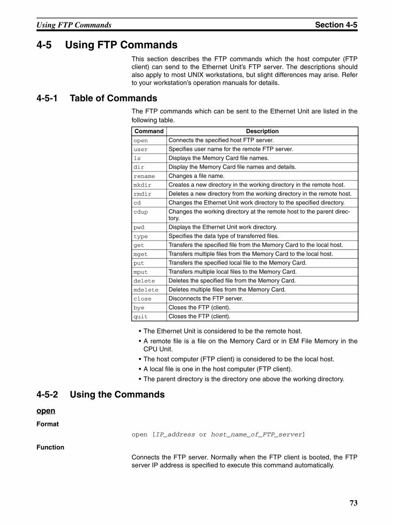
Using FTP Commands Section 4-5
4-5 Using FTP CommandsThis section describes the FTP commands which the host computer (FTPclient) can send to the Ethernet Unit’s FTP server. The descriptions shouldalso apply to most UNIX workstations, but slight differences may arise. Referto your workstation’s operation manuals for details.
4-5-1 Table of CommandsThe FTP commands which can be sent to the Ethernet Unit are listed in thefollowing table.
• The Ethernet Unit is considered to be the remote host.
• A remote file is a file on the Memory Card or in EM File Memory in theCPU Unit.
• The host computer (FTP client) is considered to be the local host.
• A local file is one in the host computer (FTP client).
• The parent directory is the directory one above the working directory.
4-5-2 Using the Commands
open
Format
open [IP_address or host_name_of_FTP_server]
Function
Connects the FTP server. Normally when the FTP client is booted, the FTPserver IP address is specified to execute this command automatically.
Command Description
open Connects the specified host FTP server.
user Specifies user name for the remote FTP server.
ls Displays the Memory Card file names.
dir Display the Memory Card file names and details.
rename Changes a file name.
mkdir Creates a new directory in the working directory in the remote host.
rmdir Deletes a new directory from the working directory in the remote host.
cd Changes the Ethernet Unit work directory to the specified directory.
cdup Changes the working directory at the remote host to the parent direc-tory.
pwd Displays the Ethernet Unit work directory.
type Specifies the data type of transferred files.
get Transfers the specified file from the Memory Card to the local host.
mget Transfers multiple files from the Memory Card to the local host.
put Transfers the specified local file to the Memory Card.
mput Transfers multiple local files to the Memory Card.
delete Deletes the specified file from the Memory Card.
mdelete Deletes multiple files from the Memory Card.
close Disconnects the FTP server.
bye Closes the FTP (client).
quit Closes the FTP (client).
73
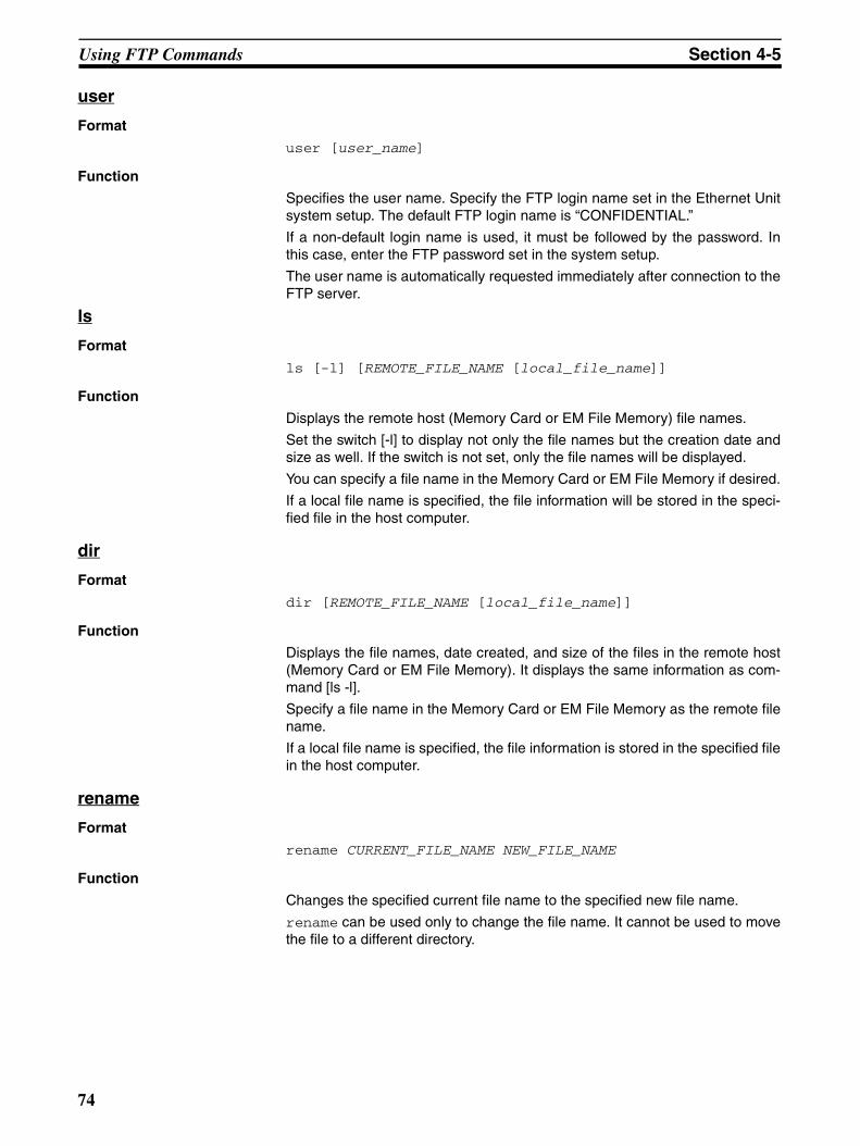
Using FTP Commands Section 4-5
user
Format
user [user_name]
Function
Specifies the user name. Specify the FTP login name set in the Ethernet Unitsystem setup. The default FTP login name is “CONFIDENTIAL.”
If a non-default login name is used, it must be followed by the password. Inthis case, enter the FTP password set in the system setup.
The user name is automatically requested immediately after connection to theFTP server.
ls
Format
ls [-l] [REMOTE_FILE_NAME [local_file_name]]
Function
Displays the remote host (Memory Card or EM File Memory) file names.
Set the switch [-l] to display not only the file names but the creation date andsize as well. If the switch is not set, only the file names will be displayed.
You can specify a file name in the Memory Card or EM File Memory if desired.
If a local file name is specified, the file information will be stored in the speci-fied file in the host computer.
dir
Format
dir [REMOTE_FILE_NAME [local_file_name]]
Function
Displays the file names, date created, and size of the files in the remote host(Memory Card or EM File Memory). It displays the same information as com-mand [ls -l].
Specify a file name in the Memory Card or EM File Memory as the remote filename.
If a local file name is specified, the file information is stored in the specified filein the host computer.
rename
Format
rename CURRENT_FILE_NAME NEW_FILE_NAME
Function
Changes the specified current file name to the specified new file name.
rename can be used only to change the file name. It cannot be used to movethe file to a different directory.
74
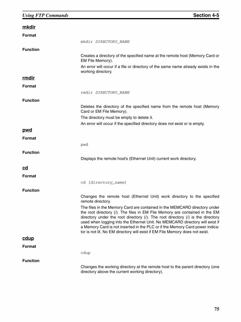
Using FTP Commands Section 4-5
mkdir
Format
mkdir DIRECTORY_NAME
Function
Creates a directory of the specified name at the remote host (Memory Card orEM File Memory).
An error will occur if a file or directory of the same name already exists in theworking directory.
rmdir
Format
rmdir DIRECTORY_NAME
Function
Deletes the directory of the specified name from the remote host (MemoryCard or EM File Memory).
The directory must be empty to delete it.
An error will occur if the specified directory does not exist or is empty.
pwd
Format
pwd
Function
Displays the remote host’s (Ethernet Unit) current work directory.
cd
Format
cd [directory_name]
Function
Changes the remote host (Ethernet Unit) work directory to the specifiedremote directory.
The files in the Memory Card are contained in the MEMCARD directory underthe root directory (/). The files in EM File Memory are contained in the EMdirectory under the root directory (/). The root directory (/) is the directoryused when logging into the Ethernet Unit. No MEMCARD directory will exist ifa Memory Card is not inserted in the PLC or if the Memory Card power indica-tor is not lit. No EM directory will exist if EM File Memory does not exist.
cdup
Format
cdup
Function
Changes the working directory at the remote host to the parent directory (onedirectory above the current working directory).
75
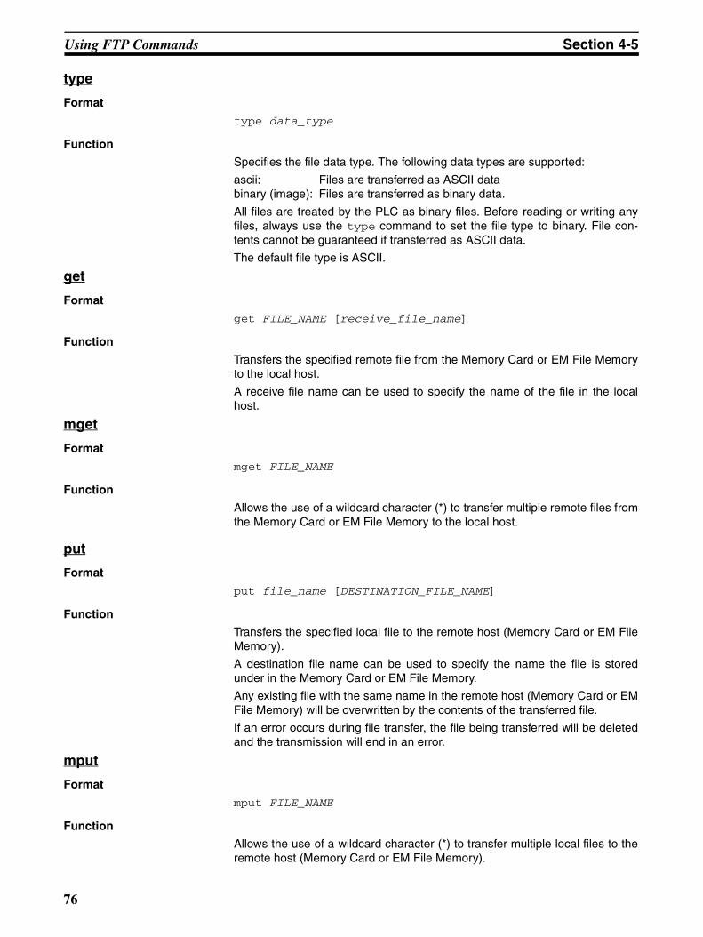
Using FTP Commands Section 4-5
type
Format
type data_type
Function
Specifies the file data type. The following data types are supported:
ascii: Files are transferred as ASCII data binary (image): Files are transferred as binary data.
All files are treated by the PLC as binary files. Before reading or writing anyfiles, always use the type command to set the file type to binary. File con-tents cannot be guaranteed if transferred as ASCII data.
The default file type is ASCII.
get
Format
get FILE_NAME [receive_file_name]
Function
Transfers the specified remote file from the Memory Card or EM File Memoryto the local host.
A receive file name can be used to specify the name of the file in the localhost.
mget
Format
mget FILE_NAME
Function
Allows the use of a wildcard character (*) to transfer multiple remote files fromthe Memory Card or EM File Memory to the local host.
put
Format
put file_name [DESTINATION_FILE_NAME]
Function
Transfers the specified local file to the remote host (Memory Card or EM FileMemory).
A destination file name can be used to specify the name the file is storedunder in the Memory Card or EM File Memory.
Any existing file with the same name in the remote host (Memory Card or EMFile Memory) will be overwritten by the contents of the transferred file.
If an error occurs during file transfer, the file being transferred will be deletedand the transmission will end in an error.
mput
Format
mput FILE_NAME
Function
Allows the use of a wildcard character (*) to transfer multiple local files to theremote host (Memory Card or EM File Memory).
76
Using FTP Commands Section 4-5
Any existing file with the same name in the remote host (Memory Card or EMFile Memory) will be overwritten by the contents of the transferred file.
If an error occurs during file transfer, the file being transferred will be deletedand the transmission of that file will end in an error. However, mput executionwill continue and remaining files will be transferred.
delete
Format
delete FILE_NAME
Function
Deletes the specified remote file from the Memory Card or EM File Memory.
mdelete
Format
mdelete FILE_NAME
Function
Allows the use of a wildcard character (*) to delete multiple remote files fromthe Memory Card or EM File Memory.
close
Format
close
Function
Disconnects the Ethernet Unit’s FTP server.
bye
Format
bye
Function
Ends the FTP (client).
quit
Format
quit
Function
Ends the FTP (client).
77
Using FTP Commands Section 4-5
4-5-3 Error Messages and FTP StatusError Messages
The error messages returned by the Ethernet Unit are listed in the followingtable.
Message Meaning
PPP is a directory. The path name indicated at PPP is a directory.
PPP is not a directory. The path name indicated at PPP is not a directory.
Another unit has access authority (FINS error 0 x 3001).
Another Unit currently has the access right.
Bad sequence of commands. The RNFR command has not been executed.
Can't create data socket (X.X.X.X, YY). A socket cannot be created.
Cannot access to device (FINS error 0 x 250F). A file device error has occurred.
Cannot get memory blocks. A message memory block cannot be allocated.
Command format error (FINS error 0 x 1003). The command format is incorrect.
Connect error. A connection error has occurred.
Directories of old and new paths are not same. The directories before and after changing the name are different.
Directory name length exceeded max. size. The directory name is too long.
Directory not empty (FINS error 0 x 2108). The directory must be empty to delete it.
Fatal error (FINS error 0 x 1101). A parameter error has occurred.
Fatal error (FINS error 0 x 1103).
File or directory already exists. The specified file or directory name already exists.
File or directory already exists (FINS error 0 x 2107).
File or directory name illegal. The file or directory name is incorrect.
File or directory name illegal (FINS error 0 x 110C).
File read error (FINS error 0 x 1104). An error occurs when reading the file.
File read error (FINS error 0 x 110B).
File write error (FINS error 0 x 2106). An error occurs when reading the file.
File write error (FINS error 0 x 2107).
FINS error MRES 0 x XX: SRES 0 x XX. Some other FINS error has occurred.
Length of directory name too long. The path name of the directory is too long.
No space to create entry (FINS error 0 x 2103). There are too many files to create a new one.
No such device (FINS error 0 x 2301). The file device cannot be found.
No such file or directory. The specified file or directory does not exist.
No such file or directory (FINS error 0 x 2006).
No such file or directory (FINS error 0 x 2106).
Not enough memory. The communications buffers are full.
Not enough space in the system. (FINS error 1104).
The file device is full.
PLC communication error (timeout). File access timed out.
Socket canceled. The socket was canceled.
Socket error NN. A socket bind error occurred. The error code will be given at NN.
Socket receive error NN. A data reception error occurred. The error code will be given at NN.
Socket send error NN. A data send error occurred. The error code will be given at NN.
Timeout (900 seconds): closing control connection. The connection was closed because the client did not respond for 15 minutes.
Too many open files. Too many sockets have been created.
Write access denied. Writing is not possible.
Write access denied. (FINS error 0 x 2101).
78
Checking FTP Status Section 4-6
PPP: Path nameXXX: IP addressYY: Port numberMM: FINS error codeNN: Socket error code
4-6 Checking FTP Status
4-6-1 FTP Status FlagThe current status of the FTP server can be obtained from the service statusin the words allocated to the Ethernet Unit in the CPU Bus Unit Area in theCIO Area. The word containing the FTP Status Flag can be computed as fol-lows: CIO 1500 + (25 x unit number) + 17
Note 1. File operations for files on the Memory Card are performed during FTPcommunications. Do not remove the Memory Card or turn OFF power tothe PLC while FTP is being used.
2. When using File Memory Instruction from the program in the CPU Unit,program exclusive control using the FTP Status Flag so that the same datais not manipulated simultaneously by more than one instruction.
3. The FTP status can also be checked using the software switch settings onthe CX-Programmer.
FTP Indicator
The FTP indicator on the Ethernet Unit indicates FTP status as shown in thefollowing table.
Status of bit 00
Meaning
1 FTP server busy (a user is connected)
0 FTP server free
FTP Status Flag
15 14 13 12 11 10 9 8 7 6 5 4 3 2 1 0n+17
FTP indicator Meaning
Lit FTP server busy (a user is connected)
Not lit FTP server free
79
Using File Memory Section 4-7
4-7 Using File MemoryThere are two media that can be used to store files in memory for CS/CJ-series PLCs:
• Memory Cards
• EM File Memory
4-7-1 File Memory
4-7-2 File Types File Names
Files are distinguished by assigning file names and extensions. The followingcharacters can be used in file names and extensions:
Alphanumeric characters: A to Z and 0 to 9. (Names converted to all-caps)! & $ # ’ [ ] - ^ ( ) _
The following characters cannot be used in files names and extensions:
, . / ? * ” : ; < > = + (spaces)
File names are not case sensitive and will be converted to all-caps in the PLCfile system. File names can be up to 8 character long with 3-character exten-sions. An error will occur if a file name or extension is too long. The first period(.) in a file name will be taken as the delimiter between the file name andextension. Extensions are determined by the file type.
Directories
Up to five levels of directories (including root as the first level) can be createdas file storage locations. A maximum of 65 characters can be used in direc-tory names.
CPU Unit
Memory Card
EM File Memory
File
File
File
File
Media Memory type Capacity Model File data recognized by CPU Unit
CS/CJ-series Memory Cards
Flash memory 8 MB HMC-EF861 • Complete user program • Specified portions of I/O Memory• Parameter area data (e.g. PLC
Setup)
15 MB HMC-EF171
30 MB HMC-EF371
EM File Memory
RAM Max. capacity of EM Area in CPU Unit
All EM Area banks from specified bank in I/O Memory (specified in PLC Setup)
80
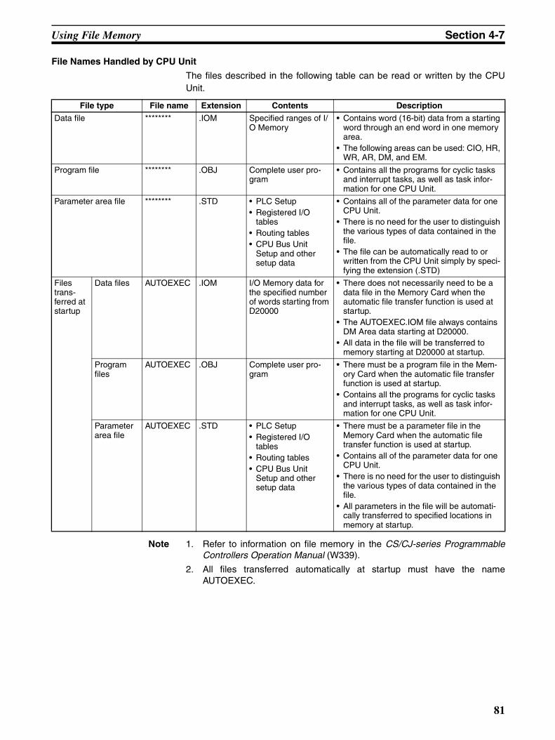
Using File Memory Section 4-7
File Names Handled by CPU Unit
The files described in the following table can be read or written by the CPUUnit.
Note 1. Refer to information on file memory in the CS/CJ-series ProgrammableControllers Operation Manual (W339).
2. All files transferred automatically at startup must have the nameAUTOEXEC.
File type File name Extension Contents Description
Data file ******** .IOM Specified ranges of I/O Memory
• Contains word (16-bit) data from a starting word through an end word in one memory area.
• The following areas can be used: CIO, HR, WR, AR, DM, and EM.
Program file ******** .OBJ Complete user pro-gram
• Contains all the programs for cyclic tasks and interrupt tasks, as well as task infor-mation for one CPU Unit.
Parameter area file ******** .STD • PLC Setup• Registered I/O
tables• Routing tables• CPU Bus Unit
Setup and other setup data
• Contains all of the parameter data for one CPU Unit.
• There is no need for the user to distinguish the various types of data contained in the file.
• The file can be automatically read to or written from the CPU Unit simply by speci-fying the extension (.STD)
Files trans-ferred at startup
Data files AUTOEXEC .IOM I/O Memory data for the specified number of words starting from D20000
• There does not necessarily need to be a data file in the Memory Card when the automatic file transfer function is used at startup.
• The AUTOEXEC.IOM file always contains DM Area data starting at D20000.
• All data in the file will be transferred to memory starting at D20000 at startup.
Program files
AUTOEXEC .OBJ Complete user pro-gram
• There must be a program file in the Mem-ory Card when the automatic file transfer function is used at startup.
• Contains all the programs for cyclic tasks and interrupt tasks, as well as task infor-mation for one CPU Unit.
Parameter area file
AUTOEXEC .STD • PLC Setup• Registered I/O
tables• Routing tables• CPU Bus Unit
Setup and other setup data
• There must be a parameter file in the Memory Card when the automatic file transfer function is used at startup.
• Contains all of the parameter data for one CPU Unit.
• There is no need for the user to distinguish the various types of data contained in the file.
• All parameters in the file will be automati-cally transferred to specified locations in memory at startup.
81
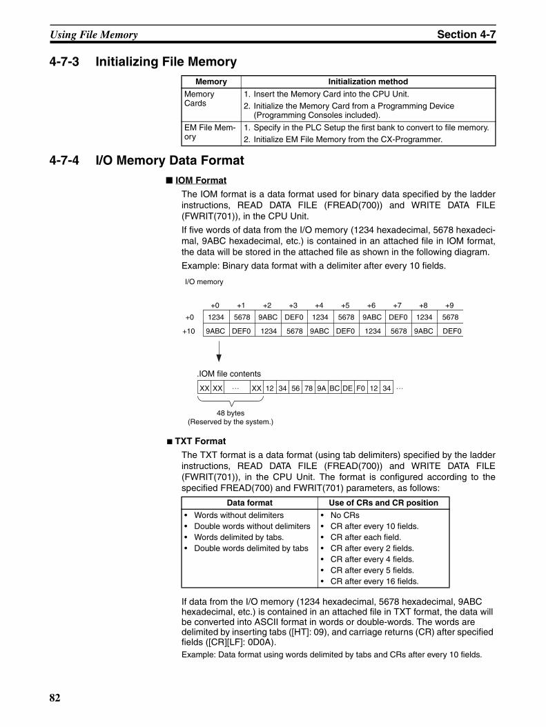
Using File Memory Section 4-7
4-7-3 Initializing File Memory
4-7-4 I/O Memory Data Format IOM Format
The IOM format is a data format used for binary data specified by the ladderinstructions, READ DATA FILE (FREAD(700)) and WRITE DATA FILE(FWRIT(701)), in the CPU Unit.
If five words of data from the I/O memory (1234 hexadecimal, 5678 hexadeci-mal, 9ABC hexadecimal, etc.) is contained in an attached file in IOM format,the data will be stored in the attached file as shown in the following diagram.
Example: Binary data format with a delimiter after every 10 fields.
TXT Format
The TXT format is a data format (using tab delimiters) specified by the ladderinstructions, READ DATA FILE (FREAD(700)) and WRITE DATA FILE(FWRIT(701)), in the CPU Unit. The format is configured according to thespecified FREAD(700) and FWRIT(701) parameters, as follows:
If data from the I/O memory (1234 hexadecimal, 5678 hexadecimal, 9ABC hexadecimal, etc.) is contained in an attached file in TXT format, the data will be converted into ASCII format in words or double-words. The words are delimited by inserting tabs ([HT]: 09), and carriage returns (CR) after specified fields ([CR][LF]: 0D0A). Example: Data format using words delimited by tabs and CRs after every 10 fields.
Memory Initialization method
Memory Cards
1. Insert the Memory Card into the CPU Unit.2. Initialize the Memory Card from a Programming Device
(Programming Consoles included).
EM File Mem-ory
1. Specify in the PLC Setup the first bank to convert to file memory.2. Initialize EM File Memory from the CX-Programmer.
+0 +1 +2 +3 +4 +5 +6 +7 +8 +9
+0 1234 5678 9ABC DEF0 1234 5678 9ABC DEF0 1234 5678
+10 9ABC DEF0 1234 5678 9ABC DEF0 1234 5678 9ABC DEF0
XX XX XX 12 34 56 78 9A BC DE F0 12 34
I/O memory
.IOM file contents
48 bytes(Reserved by the system.)
Data format Use of CRs and CR position
• Words without delimiters• Double words without delimiters• Words delimited by tabs.• Double words delimited by tabs
• No CRs• CR after every 10 fields.• CR after each field.• CR after every 2 fields.• CR after every 4 fields.• CR after every 5 fields.• CR after every 16 fields.
82
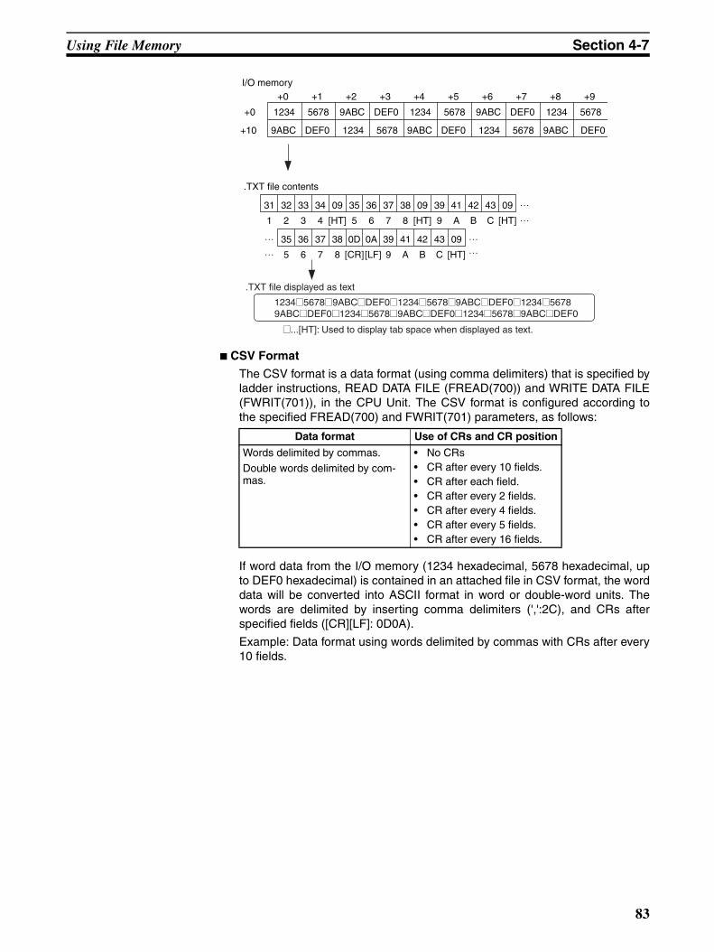
Using File Memory Section 4-7
CSV Format
The CSV format is a data format (using comma delimiters) that is specified byladder instructions, READ DATA FILE (FREAD(700)) and WRITE DATA FILE(FWRIT(701)), in the CPU Unit. The CSV format is configured according tothe specified FREAD(700) and FWRIT(701) parameters, as follows:
If word data from the I/O memory (1234 hexadecimal, 5678 hexadecimal, upto DEF0 hexadecimal) is contained in an attached file in CSV format, the worddata will be converted into ASCII format in word or double-word units. Thewords are delimited by inserting comma delimiters (',':2C), and CRs afterspecified fields ([CR][LF]: 0D0A).
Example: Data format using words delimited by commas with CRs after every10 fields.
+0 +1 +2 +3 +4 +5 +6 +7 +8 +9
+0 1234 5678 9ABC DEF0 1234 5678 9ABC DEF0 1234 5678
+10 9ABC DEF0 1234 5678 9ABC DEF0 1234 5678 9ABC DEF0
31 32 33 34 09 35 36 37 38 09 39 41 42 43 09
I/O memory
.TXT file contents
1 2 3 4 [HT] 5 6 7 8 [HT] 9 A B C [HT]
35 36 37 38 0D 0A 39 41 42 43 09
5 6 7 8 [CR][LF] 9 A B C [HT]
1234@5678@9ABC@DEF0@1234@5678@9ABC@DEF0@1234@56789ABC@DEF0@1234@5678@9ABC@DEF0@1234@5678@9ABC@DEF0
@...[HT]: Used to display tab space when displayed as text.
.TXT file displayed as text
Data format Use of CRs and CR position
Words delimited by commas.Double words delimited by com-mas.
• No CRs• CR after every 10 fields.• CR after each field.• CR after every 2 fields.• CR after every 4 fields.• CR after every 5 fields.• CR after every 16 fields.
83
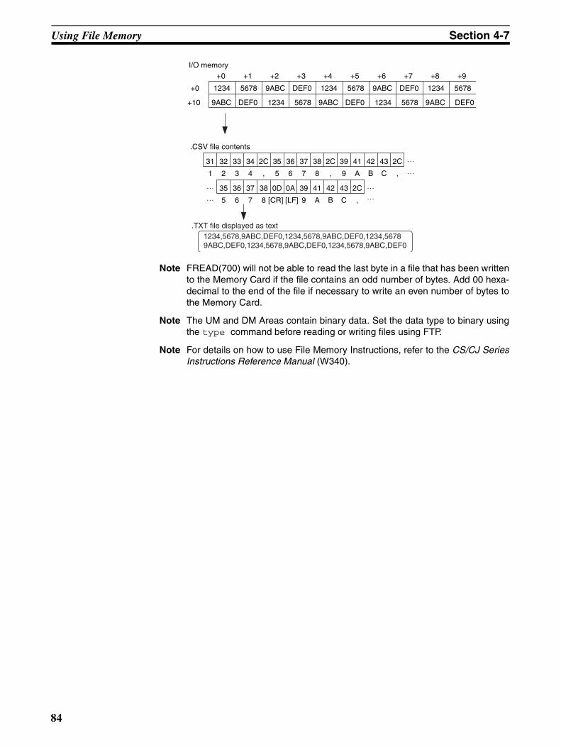
Using File Memory Section 4-7
Note FREAD(700) will not be able to read the last byte in a file that has been writtento the Memory Card if the file contains an odd number of bytes. Add 00 hexa-decimal to the end of the file if necessary to write an even number of bytes tothe Memory Card.
Note The UM and DM Areas contain binary data. Set the data type to binary usingthe type command before reading or writing files using FTP.
Note For details on how to use File Memory Instructions, refer to the CS/CJ SeriesInstructions Reference Manual (W340).
+0 +1 +2 +3 +4 +5 +6 +7 +8 +9
+0 1234 5678 9ABC DEF0 1234 5678 9ABC DEF0 1234 5678
+10 9ABC DEF0 1234 5678 9ABC DEF0 1234 5678 9ABC DEF0
31 32 33 34 2C 35 36 37 38 2C 39 41 42 43 2C
I/O memory
.CSV file contents
1 2 3 4 , 5 6 7 8 , 9 A B C ,
35 36 37 38 0D 0A 39 41 42 43 2C
5 6 7 8 [CR] [LF] 9 A B C ,
1234,5678,9ABC,DEF0,1234,5678,9ABC,DEF0,1234,56789ABC,DEF0,1234,5678,9ABC,DEF0,1234,5678,9ABC,DEF0
.TXT file displayed as text
84
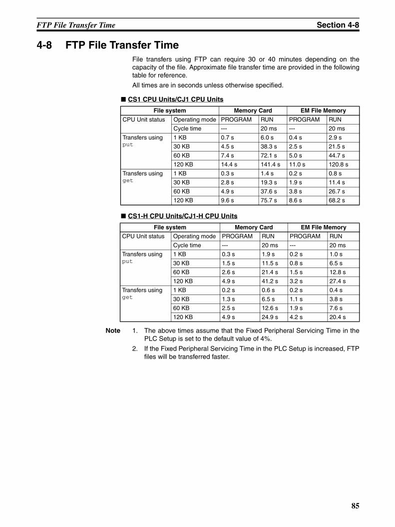
FTP File Transfer Time Section 4-8
4-8 FTP File Transfer TimeFile transfers using FTP can require 30 or 40 minutes depending on thecapacity of the file. Approximate file transfer time are provided in the followingtable for reference.
All times are in seconds unless otherwise specified.
CS1 CPU Units/CJ1 CPU Units
CS1-H CPU Units/CJ1-H CPU Units
Note 1. The above times assume that the Fixed Peripheral Servicing Time in thePLC Setup is set to the default value of 4%.
2. If the Fixed Peripheral Servicing Time in the PLC Setup is increased, FTPfiles will be transferred faster.
File system Memory Card EM File Memory
CPU Unit status Operating mode PROGRAM RUN PROGRAM RUN
Cycle time --- 20 ms --- 20 ms
Transfers using put
1 KB 0.7 s 6.0 s 0.4 s 2.9 s
30 KB 4.5 s 38.3 s 2.5 s 21.5 s
60 KB 7.4 s 72.1 s 5.0 s 44.7 s
120 KB 14.4 s 141.4 s 11.0 s 120.8 s
Transfers using get
1 KB 0.3 s 1.4 s 0.2 s 0.8 s
30 KB 2.8 s 19.3 s 1.9 s 11.4 s
60 KB 4.9 s 37.6 s 3.8 s 26.7 s
120 KB 9.6 s 75.7 s 8.6 s 68.2 s
File system Memory Card EM File Memory
CPU Unit status Operating mode PROGRAM RUN PROGRAM RUN
Cycle time --- 20 ms --- 20 ms
Transfers using put
1 KB 0.3 s 1.9 s 0.2 s 1.0 s
30 KB 1.5 s 11.5 s 0.8 s 6.5 s
60 KB 2.6 s 21.4 s 1.5 s 12.8 s
120 KB 4.9 s 41.2 s 3.2 s 27.4 s
Transfers using get
1 KB 0.2 s 0.6 s 0.2 s 0.4 s
30 KB 1.3 s 6.5 s 1.1 s 3.8 s
60 KB 2.5 s 12.6 s 1.9 s 7.6 s
120 KB 4.9 s 24.9 s 4.2 s 20.4 s
85
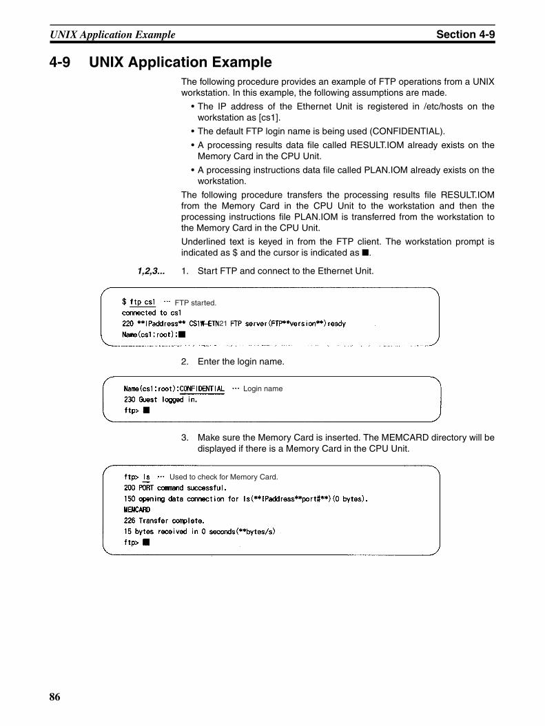
UNIX Application Example Section 4-9
4-9 UNIX Application ExampleThe following procedure provides an example of FTP operations from a UNIXworkstation. In this example, the following assumptions are made.
• The IP address of the Ethernet Unit is registered in /etc/hosts on theworkstation as [cs1].
• The default FTP login name is being used (CONFIDENTIAL).
• A processing results data file called RESULT.IOM already exists on theMemory Card in the CPU Unit.
• A processing instructions data file called PLAN.IOM already exists on theworkstation.
The following procedure transfers the processing results file RESULT.IOMfrom the Memory Card in the CPU Unit to the workstation and then theprocessing instructions file PLAN.IOM is transferred from the workstation tothe Memory Card in the CPU Unit.
Underlined text is keyed in from the FTP client. The workstation prompt isindicated as $ and the cursor is indicated as .
1,2,3... 1. Start FTP and connect to the Ethernet Unit.
2. Enter the login name.
3. Make sure the Memory Card is inserted. The MEMCARD directory will bedisplayed if there is a Memory Card in the CPU Unit.
FTP started.
21
Login name
Used to check for Memory Card.
86
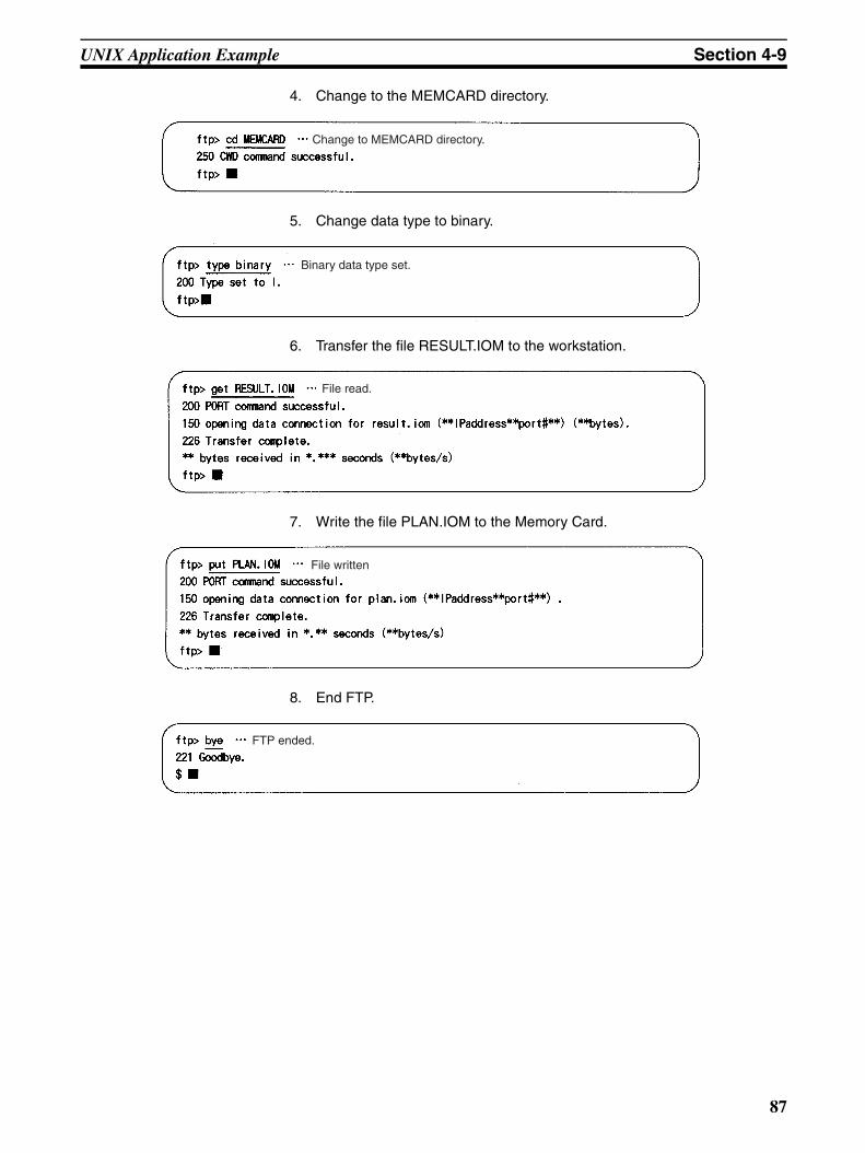
UNIX Application Example Section 4-9
4. Change to the MEMCARD directory.
5. Change data type to binary.
6. Transfer the file RESULT.IOM to the workstation.
7. Write the file PLAN.IOM to the Memory Card.
8. End FTP.
Change to MEMCARD directory.
Binary data type set.
File read.
File written
FTP ended.
87

UNIX Application Example Section 4-9
88
SECTION 5Automatic Clock Adjustment Function
This section provides an overview of the automatic clock adjustment function, including details on specifications, requiredsettings, operations from CX-Programmer, and troubleshooting.
5-1 Overview . . . . . . . . . . . . . . . . . . . . . . . . . . . . . . . . . . . . . . . . . . . . . . . . . . . . . 90
5-1-1 Overview. . . . . . . . . . . . . . . . . . . . . . . . . . . . . . . . . . . . . . . . . . . . . . 90
5-1-2 Specifications . . . . . . . . . . . . . . . . . . . . . . . . . . . . . . . . . . . . . . . . . . 91
5-2 Using the Automatic Clock Adjustment Function . . . . . . . . . . . . . . . . . . . . . 91
5-2-1 Procedure . . . . . . . . . . . . . . . . . . . . . . . . . . . . . . . . . . . . . . . . . . . . . 91
5-2-2 Settings Required for Automatic Clock Adjustment Function. . . . . 92
5-2-3 Auto Adjust Time . . . . . . . . . . . . . . . . . . . . . . . . . . . . . . . . . . . . . . . 93
5-3 Automatic Clock Adjustment Switch . . . . . . . . . . . . . . . . . . . . . . . . . . . . . . . 94
5-4 Automatic Clock Adjustment Error Processing . . . . . . . . . . . . . . . . . . . . . . . 94
5-4-1 Automatic Clock Adjustment (SNTP) Errors. . . . . . . . . . . . . . . . . . 94
5-4-2 Troubleshooting Automatic Clock Adjustment Errors with Indicators 94
5-4-3 Error Log Error Codes for the Automatic Clock Adjustment Function 95
89
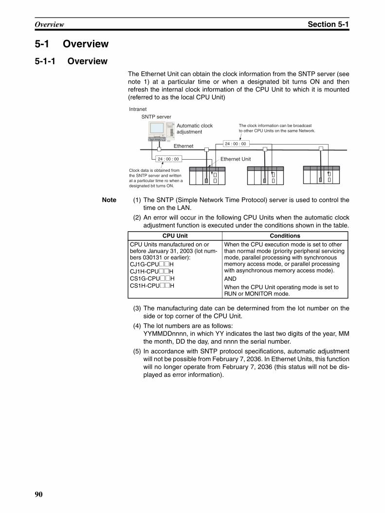
Overview Section 5-1
5-1 Overview
5-1-1 OverviewThe Ethernet Unit can obtain the clock information from the SNTP server (seenote 1) at a particular time or when a designated bit turns ON and thenrefresh the internal clock information of the CPU Unit to which it is mounted(referred to as the local CPU Unit)
Note (1) The SNTP (Simple Network Time Protocol) server is used to control thetime on the LAN.
(2) An error will occur in the following CPU Units when the automatic clockadjustment function is executed under the conditions shown in the table.
(3) The manufacturing date can be determined from the lot number on theside or top corner of the CPU Unit.
(4) The lot numbers are as follows:YYMMDDnnnn, in which YY indicates the last two digits of the year, MMthe month, DD the day, and nnnn the serial number.
(5) In accordance with SNTP protocol specifications, automatic adjustmentwill not be possible from February 7, 2036. In Ethernet Units, this functionwill no longer operate from February 7, 2036 (this status will not be dis-played as error information).
24 : 00 : 00
Intranet
SNTP server
Automatic clock adjustment
Ethernet
Ethernet Unit
The clock information can be broadcast to other CPU Units on the same Network.
24 : 00 : 00
Clock data is obtained from the SNTP server and written at a particular time ro when a designated bit turns ON.
CPU Unit Conditions
CPU Units manufactured on or before January 31, 2003 (lot num-bers 030131 or earlier):CJ1G-CPU@@HCJ1H-CPU@@HCS1G-CPU@@HCS1H-CPU@@H
When the CPU execution mode is set to other than normal mode (priority peripheral servicing mode, parallel processing with synchronous memory access mode, or parallel processing with asynchronous memory access mode).ANDWhen the CPU Unit operating mode is set to RUN or MONITOR mode.
90
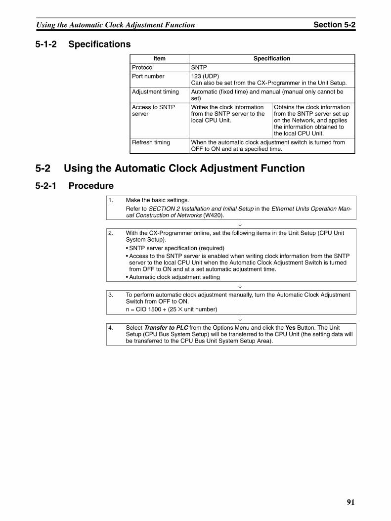
Using the Automatic Clock Adjustment Function Section 5-2
5-1-2 Specifications
5-2 Using the Automatic Clock Adjustment Function
5-2-1 Procedure
Item Specification
Protocol SNTP
Port number 123 (UDP)Can also be set from the CX-Programmer in the Unit Setup.
Adjustment timing Automatic (fixed time) and manual (manual only cannot be set)
Access to SNTP server
Writes the clock information from the SNTP server to the local CPU Unit.
Obtains the clock information from the SNTP server set up on the Network, and applies the information obtained to the local CPU Unit.
Refresh timing When the automatic clock adjustment switch is turned from OFF to ON and at a specified time.
1. Make the basic settings.
Refer to SECTION 2 Installation and Initial Setup in the Ethernet Units Operation Man-ual Construction of Networks (W420).
↓2. With the CX-Programmer online, set the following items in the Unit Setup (CPU Unit
System Setup).
• SNTP server specification (required)• Access to the SNTP server is enabled when writing clock information from the SNTP
server to the local CPU Unit when the Automatic Clock Adjustment Switch is turned from OFF to ON and at a set automatic adjustment time.
• Automatic clock adjustment setting
↓3. To perform automatic clock adjustment manually, turn the Automatic Clock Adjustment
Switch from OFF to ON.n = CIO 1500 + (25 × unit number)
↓4. Select Transfer to PLC from the Options Menu and click the Yes Button. The Unit
Setup (CPU Bus System Setup) will be transferred to the CPU Unit (the setting data will be transferred to the CPU Bus Unit System Setup Area).
91
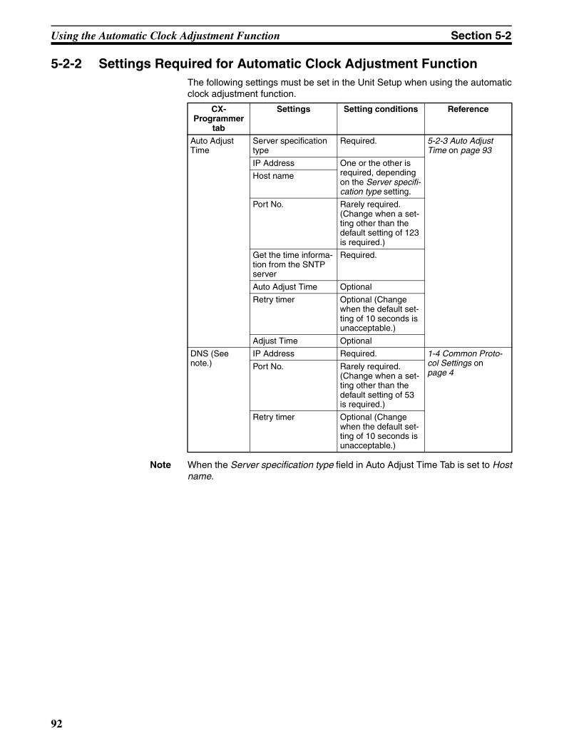
Using the Automatic Clock Adjustment Function Section 5-2
5-2-2 Settings Required for Automatic Clock Adjustment FunctionThe following settings must be set in the Unit Setup when using the automaticclock adjustment function.
Note When the Server specification type field in Auto Adjust Time Tab is set to Hostname.
CX-Programmer
tab
Settings Setting conditions Reference
Auto Adjust Time
Server specification type
Required. 5-2-3 Auto Adjust Time on page 93
IP Address One or the other is required, depending on the Server specifi-cation type setting.
Host name
Port No. Rarely required. (Change when a set-ting other than the default setting of 123 is required.)
Get the time informa-tion from the SNTP server
Required.
Auto Adjust Time Optional
Retry timer Optional (Change when the default set-ting of 10 seconds is unacceptable.)
Adjust Time Optional
DNS (See note.)
IP Address Required. 1-4 Common Proto-col Settings on page 4
Port No. Rarely required. (Change when a set-ting other than the default setting of 53 is required.)
Retry timer Optional (Change when the default set-ting of 10 seconds is unacceptable.)
92
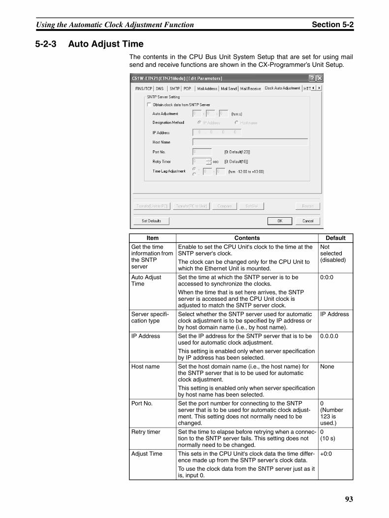
Using the Automatic Clock Adjustment Function Section 5-2
5-2-3 Auto Adjust TimeThe contents in the CPU Bus Unit System Setup that are set for using mailsend and receive functions are shown in the CX-Programmer’s Unit Setup.
Item Contents Default
Get the time information from the SNTP server
Enable to set the CPU Unit's clock to the time at the SNTP server's clock.The clock can be changed only for the CPU Unit to which the Ethernet Unit is mounted.
Not selected (disabled)
Auto Adjust Time
Set the time at which the SNTP server is to be accessed to synchronize the clocks.
When the time that is set here arrives, the SNTP server is accessed and the CPU Unit clock is adjusted to match the SNTP server clock.
0:0:0
Server specifi-cation type
Select whether the SNTP server used for automatic clock adjustment is to be specified by IP address or by host domain name (i.e., by host name).
IP Address
IP Address Set the IP address for the SNTP server that is to be used for automatic clock adjustment.
This setting is enabled only when server specification by IP address has been selected.
0.0.0.0
Host name Set the host domain name (i.e., the host name) for the SNTP server that is to be used for automatic clock adjustment.
This setting is enabled only when server specification by host name has been selected.
None
Port No. Set the port number for connecting to the SNTP server that is to be used for automatic clock adjust-ment. This setting does not normally need to be changed.
0(Number 123 is used.)
Retry timer Set the time to elapse before retrying when a connec-tion to the SNTP server fails. This setting does not normally need to be changed.
0(10 s)
Adjust Time This sets in the CPU Unit's clock data the time differ-ence made up from the SNTP server's clock data.
To use the clock data from the SNTP server just as it is, input 0.
+0:0
93
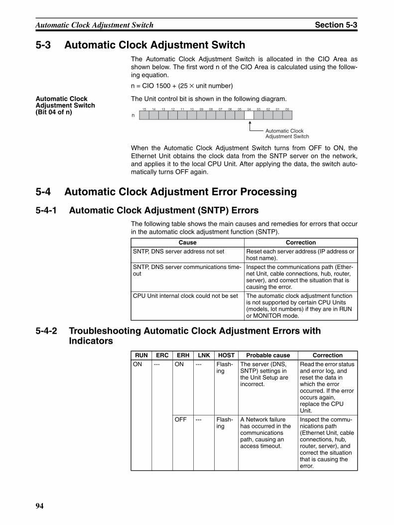
Automatic Clock Adjustment Switch Section 5-3
5-3 Automatic Clock Adjustment SwitchThe Automatic Clock Adjustment Switch is allocated in the CIO Area asshown below. The first word n of the CIO Area is calculated using the follow-ing equation.
n = CIO 1500 + (25 × unit number)
Automatic Clock Adjustment Switch(Bit 04 of n)
The Unit control bit is shown in the following diagram.
When the Automatic Clock Adjustment Switch turns from OFF to ON, theEthernet Unit obtains the clock data from the SNTP server on the network,and applies it to the local CPU Unit. After applying the data, the switch auto-matically turns OFF again.
5-4 Automatic Clock Adjustment Error Processing
5-4-1 Automatic Clock Adjustment (SNTP) ErrorsThe following table shows the main causes and remedies for errors that occurin the automatic clock adjustment function (SNTP).
5-4-2 Troubleshooting Automatic Clock Adjustment Errors with Indicators
15 14 13 12 11 10 09 08 07 06 05 04 03 02 01 00
n
Automatic Clock Adjustment Switch
Cause Correction
SNTP, DNS server address not set Reset each server address (IP address or host name).
SNTP, DNS server communications time-out
Inspect the communications path (Ether-net Unit, cable connections, hub, router, server), and correct the situation that is causing the error.
CPU Unit internal clock could not be set The automatic clock adjustment function is not supported by certain CPU Units (models, lot numbers) if they are in RUN or MONITOR mode.
RUN ERC ERH LNK HOST Probable cause Correction
ON --- ON --- Flash-ing
The server (DNS, SNTP) settings in the Unit Setup are incorrect.
Read the error status and error log, and reset the data in which the error occurred. If the error occurs again, replace the CPU Unit.
OFF --- Flash-ing
A Network failure has occurred in the communications path, causing an access timeout.
Inspect the commu-nications path (Ethernet Unit, cable connections, hub, router, server), and correct the situation that is causing the error.
94
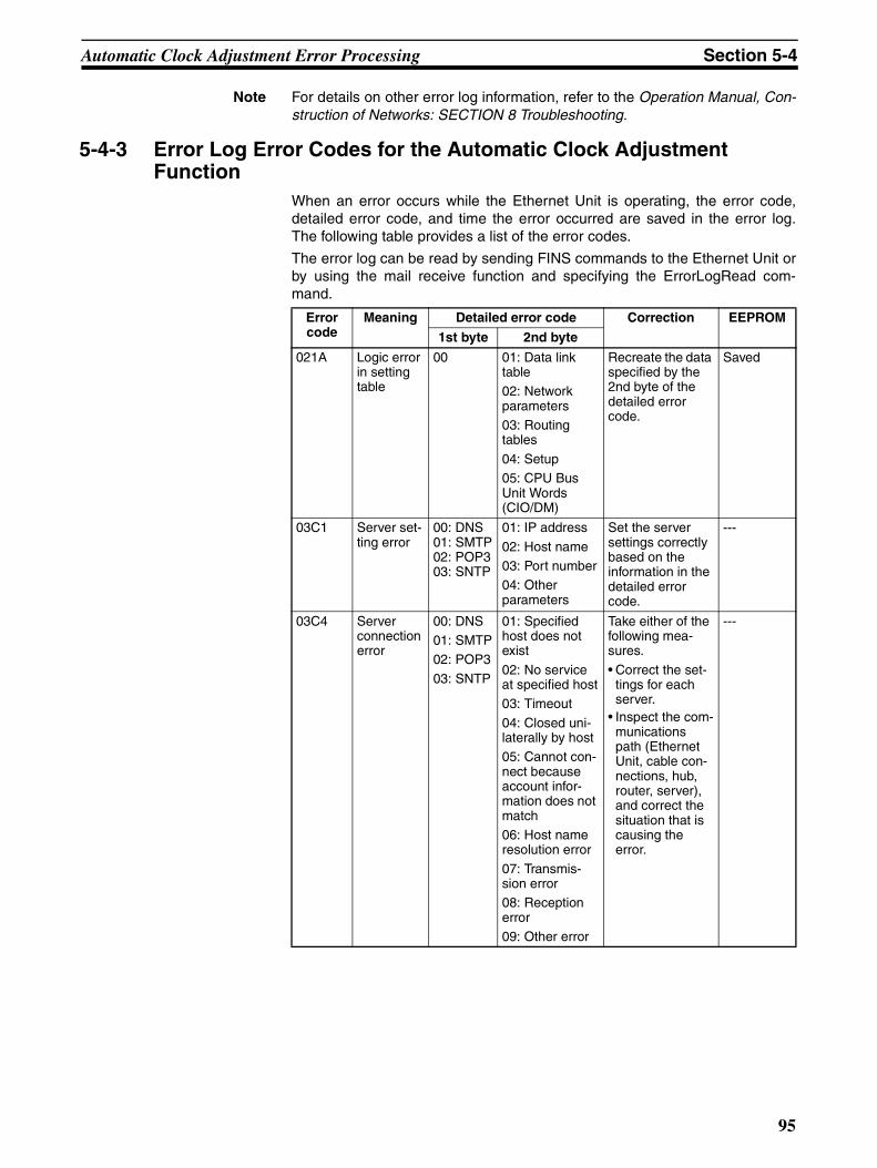
Automatic Clock Adjustment Error Processing Section 5-4
Note For details on other error log information, refer to the Operation Manual, Con-struction of Networks: SECTION 8 Troubleshooting.
5-4-3 Error Log Error Codes for the Automatic Clock Adjustment Function
When an error occurs while the Ethernet Unit is operating, the error code,detailed error code, and time the error occurred are saved in the error log.The following table provides a list of the error codes.
The error log can be read by sending FINS commands to the Ethernet Unit orby using the mail receive function and specifying the ErrorLogRead com-mand.
Error code
Meaning Detailed error code Correction EEPROM
1st byte 2nd byte
021A Logic error in setting table
00 01: Data link table02: Network parameters03: Routing tables
04: Setup05: CPU Bus Unit Words (CIO/DM)
Recreate the data specified by the 2nd byte of the detailed error code.
Saved
03C1 Server set-ting error
00: DNS01: SMTP02: POP303: SNTP
01: IP address
02: Host name03: Port number04: Other parameters
Set the server settings correctly based on the information in the detailed error code.
---
03C4 Server connection error
00: DNS01: SMTP02: POP3
03: SNTP
01: Specified host does not exist
02: No service at specified host03: Timeout
04: Closed uni-laterally by host05: Cannot con-nect because account infor-mation does not match06: Host name resolution error
07: Transmis-sion error08: Reception error09: Other error
Take either of the following mea-sures.
• Correct the set-tings for each server.
• Inspect the com-munications path (Ethernet Unit, cable con-nections, hub, router, server), and correct the situation that is causing the error.
---
95
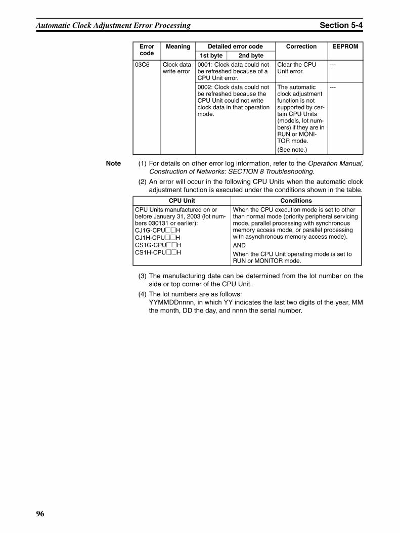
Automatic Clock Adjustment Error Processing Section 5-4
Note (1) For details on other error log information, refer to the Operation Manual,Construction of Networks: SECTION 8 Troubleshooting.
(2) An error will occur in the following CPU Units when the automatic clockadjustment function is executed under the conditions shown in the table.
(3) The manufacturing date can be determined from the lot number on theside or top corner of the CPU Unit.
(4) The lot numbers are as follows:YYMMDDnnnn, in which YY indicates the last two digits of the year, MMthe month, DD the day, and nnnn the serial number.
03C6 Clock data write error
0001: Clock data could not be refreshed because of a CPU Unit error.
Clear the CPU Unit error.
---
0002: Clock data could not be refreshed because the CPU Unit could not write clock data in that operation mode.
The automatic clock adjustment function is not supported by cer-tain CPU Units (models, lot num-bers) if they are in RUN or MONI-TOR mode.
(See note.)
---
Error code
Meaning Detailed error code Correction EEPROM
1st byte 2nd byte
CPU Unit Conditions
CPU Units manufactured on or before January 31, 2003 (lot num-bers 030131 or earlier):CJ1G-CPU@@HCJ1H-CPU@@HCS1G-CPU@@HCS1H-CPU@@H
When the CPU execution mode is set to other than normal mode (priority peripheral servicing mode, parallel processing with synchronous memory access mode, or parallel processing with asynchronous memory access mode).
ANDWhen the CPU Unit operating mode is set to RUN or MONITOR mode.
96
SECTION 6Socket Services
This section describes the functionality provided by the Ethernet Unit via the socket services.
6-1 Overview of Socket Communications from Ethernet Units . . . . . . . . . . . . . . 99
6-1-1 What are Sockets?. . . . . . . . . . . . . . . . . . . . . . . . . . . . . . . . . . . . . . . 99
6-1-2 Socket Port Numbers . . . . . . . . . . . . . . . . . . . . . . . . . . . . . . . . . . . . 99
6-2 Protocol Overview. . . . . . . . . . . . . . . . . . . . . . . . . . . . . . . . . . . . . . . . . . . . . . 100
6-2-1 Differences between TCP and UDP . . . . . . . . . . . . . . . . . . . . . . . . . 100
6-2-2 Opening TCP Sockets. . . . . . . . . . . . . . . . . . . . . . . . . . . . . . . . . . . . 100
6-2-3 Fragmentation of Send Data . . . . . . . . . . . . . . . . . . . . . . . . . . . . . . . 102
6-3 Overview . . . . . . . . . . . . . . . . . . . . . . . . . . . . . . . . . . . . . . . . . . . . . . . . . . . . . 103
6-3-1 Socket Service Functions . . . . . . . . . . . . . . . . . . . . . . . . . . . . . . . . . 103
6-3-2 Using Socket Services with Socket Service Request Switches . . . . 104
6-3-3 Using Socket Services with CMND(490). . . . . . . . . . . . . . . . . . . . . 105
6-3-4 Specific Socket Service Functions . . . . . . . . . . . . . . . . . . . . . . . . . . 105
6-3-5 Differences with Previous Models . . . . . . . . . . . . . . . . . . . . . . . . . . 106
6-4 Socket Service Function Guide. . . . . . . . . . . . . . . . . . . . . . . . . . . . . . . . . . . . 106
6-4-1 Manipulating Dedicated Control Bits . . . . . . . . . . . . . . . . . . . . . . . . 106
6-4-2 Executing CMND(490) . . . . . . . . . . . . . . . . . . . . . . . . . . . . . . . . . . 106
6-5 Using Socket Service Functions . . . . . . . . . . . . . . . . . . . . . . . . . . . . . . . . . . . 107
6-5-1 Procedure . . . . . . . . . . . . . . . . . . . . . . . . . . . . . . . . . . . . . . . . . . . . . 107
6-5-2 Settings Required for Socket Service Function . . . . . . . . . . . . . . . . 107
6-5-3 Setup Tab . . . . . . . . . . . . . . . . . . . . . . . . . . . . . . . . . . . . . . . . . . . . . 108
6-6 Socket Service Status . . . . . . . . . . . . . . . . . . . . . . . . . . . . . . . . . . . . . . . . . . . 110
6-6-1 CIO Area Allocations . . . . . . . . . . . . . . . . . . . . . . . . . . . . . . . . . . . . 110
6-6-2 DM Area Allocations . . . . . . . . . . . . . . . . . . . . . . . . . . . . . . . . . . . . 111
6-7 Using Socket Services by Manipulating Dedicated Control Bits . . . . . . . . . . 113
6-7-1 Application Procedure . . . . . . . . . . . . . . . . . . . . . . . . . . . . . . . . . . . 113
6-7-2 Socket Services and Socket Status . . . . . . . . . . . . . . . . . . . . . . . . . . 114
6-7-3 Socket Service Parameters . . . . . . . . . . . . . . . . . . . . . . . . . . . . . . . . 115
6-7-4 Parameters. . . . . . . . . . . . . . . . . . . . . . . . . . . . . . . . . . . . . . . . . . . . . 117
6-7-5 Socket Service Request Switches . . . . . . . . . . . . . . . . . . . . . . . . . . . 119
6-7-6 Response Codes . . . . . . . . . . . . . . . . . . . . . . . . . . . . . . . . . . . . . . . . 120
6-7-7 Timing Charts . . . . . . . . . . . . . . . . . . . . . . . . . . . . . . . . . . . . . . . . . . 125
6-7-8 TCP/IP Communications Programming Example . . . . . . . . . . . . . . 127
6-7-9 UDP/IP Communications Programming Example . . . . . . . . . . . . . . 131
97
6-8 Using Socket Services with CMND(490) . . . . . . . . . . . . . . . . . . . . . . . . . . . . 135
6-8-1 Using Socket Service . . . . . . . . . . . . . . . . . . . . . . . . . . . . . . . . . . . . 135
6-8-2 Socket Services and Socket Status . . . . . . . . . . . . . . . . . . . . . . . . . . 136
6-8-3 Basic FINS Command Format . . . . . . . . . . . . . . . . . . . . . . . . . . . . . 137
6-8-4 Response Codes in the Command Response. . . . . . . . . . . . . . . . . . . 138
6-8-5 Response Codes in the Results Storage Areas . . . . . . . . . . . . . . . . . 138
6-8-6 Communications Timing Chart . . . . . . . . . . . . . . . . . . . . . . . . . . . . . 138
6-8-7 Socket Service Timing Chart . . . . . . . . . . . . . . . . . . . . . . . . . . . . . . 138
6-8-8 TCP/IP Communications Programming Example . . . . . . . . . . . . . . 140
6-8-9 UDP/IP Communications Programming Example . . . . . . . . . . . . . . 148
6-9 Precautions in Using Socket Services . . . . . . . . . . . . . . . . . . . . . . . . . . . . . . . 154
6-9-1 UDP and TCP Socket Services . . . . . . . . . . . . . . . . . . . . . . . . . . . . . 154
6-9-2 UDP Socket Service . . . . . . . . . . . . . . . . . . . . . . . . . . . . . . . . . . . . . 154
6-9-3 TCP Socket Service. . . . . . . . . . . . . . . . . . . . . . . . . . . . . . . . . . . . . . 154
6-9-4 Precautions in Using Socket Service Request Switches . . . . . . . . . . 155
6-9-5 Times Required for Sending and Receiving for Socket Services . . . 156
98
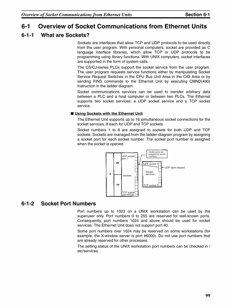
Overview of Socket Communications from Ethernet Units Section 6-1
6-1 Overview of Socket Communications from Ethernet Units6-1-1 What are Sockets?
Sockets are interfaces that allow TCP and UDP protocols to be used directlyfrom the user program. With personal computers, socket are provided as Clanguage interface libraries, which allow TCP or UDP protocols to beprogramming using library functions. With UNIX computers, socket interfacesare supported in the form of system calls.
The CS/CJ-series PLCs support the socket service from the user program.The user program requests service functions either by manipulating SocketService Request Switches in the CPU Bus Unit Area in the CIO Area or bysending FINS commands to the Ethernet Unit by executing CMND(490)instruction in the ladder diagram.
Socket communications services can be used to transfer arbitrary databetween a PLC and a host computer or between two PLCs. The Ethernetsupports two socket services: a UDP socket service and a TCP socketservice.
Using Sockets with the Ethernet Unit
The Ethernet Unit supports up to 16 simultaneous socket connections for thesocket services, 8 each for UDP and TCP sockets.
Socket numbers 1 to 8 are assigned to sockets for both UDP and TCPsockets. Sockets are managed from the ladder-diagram program by assigninga socket port for each socket number. The socket port number is assignedwhen the socket is opened.
6-1-2 Socket Port NumbersPort numbers up to 1023 on a UNIX workstation can be used by thesuperuser only. Port numbers 0 to 255 are reserved for well-known ports.Consequently, port numbers 1024 and above should be used for socketservices. The Ethernet Unit does not support port #0.
Some port numbers over 1024 may be reserved on some workstations (forexample, the X-window server is port #6000). Do not use port numbers thatare already reserved for other processes.
The setting status of the UNIX workstation port numbers can be checked in /etc/services.
UDP socket port 1
TCP socket port 65535
Sockets
Socket ports are assigned to socket numbers.
UDP socket 1
TCP socket 8
Socket services
UDP open request
99
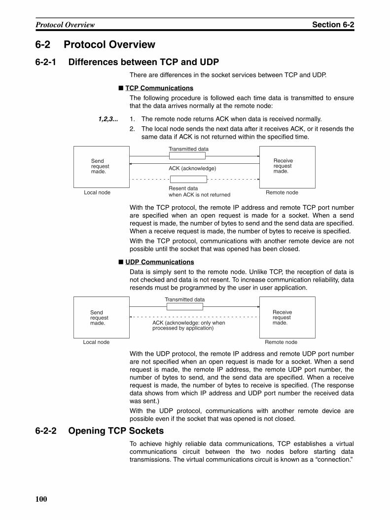
Protocol Overview Section 6-2
6-2 Protocol Overview
6-2-1 Differences between TCP and UDPThere are differences in the socket services between TCP and UDP.
TCP Communications
The following procedure is followed each time data is transmitted to ensurethat the data arrives normally at the remote node:
1,2,3... 1. The remote node returns ACK when data is received normally.
2. The local node sends the next data after it receives ACK, or it resends thesame data if ACK is not returned within the specified time.
With the TCP protocol, the remote IP address and remote TCP port numberare specified when an open request is made for a socket. When a sendrequest is made, the number of bytes to send and the send data are specified.When a receive request is made, the number of bytes to receive is specified.
With the TCP protocol, communications with another remote device are notpossible until the socket that was opened has been closed.
UDP Communications
Data is simply sent to the remote node. Unlike TCP, the reception of data isnot checked and data is not resent. To increase communication reliability, dataresends must be programmed by the user in user application.
With the UDP protocol, the remote IP address and remote UDP port numberare not specified when an open request is made for a socket. When a sendrequest is made, the remote IP address, the remote UDP port number, thenumber of bytes to send, and the send data are specified. When a receiverequest is made, the number of bytes to receive is specified. (The responsedata shows from which IP address and UDP port number the received datawas sent.)
With the UDP protocol, communications with another remote device arepossible even if the socket that was opened is not closed.
6-2-2 Opening TCP SocketsTo achieve highly reliable data communications, TCP establishes a virtualcommunications circuit between the two nodes before starting datatransmissions. The virtual communications circuit is known as a “connection.”
Local node
Transmitted data
ACK (acknowledge)
Remote node
Send request made.
Receive request made.
Resent data when ACK is not returned
Local node Remote node
Transmitted data
ACK (acknowledge: only when processed by application)
Send request made.
Receive request made.
100
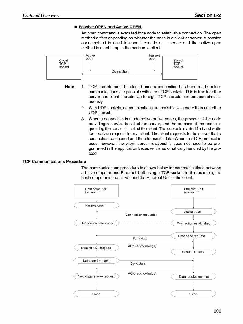
Protocol Overview Section 6-2
Passive OPEN and Active OPEN
An open command is executed for a node to establish a connection. The openmethod differs depending on whether the node is a client or server. A passiveopen method is used to open the node as a server and the active openmethod is used to open the node as a client.
Note 1. TCP sockets must be closed once a connection has been made beforecommunications are possible with other TCP sockets. This is true for otherserver and client sockets. Up to eight TCP sockets can be open simulta-neously.
2. With UDP sockets, communications are possible with more than one otherUDP socket.
3. When a connection is made between two nodes, the process at the nodeproviding a service is called the server, and the process at the node re-questing the service is called the client. The server is started first and waitsfor a service request from a client. The client requests to the server that aconnection be opened and then transmits data. When the TCP protocol isused, however, the client–server relationship does not need to be pro-grammed in the application because it is automatically handled by the pro-tocol.
TCP Communications Procedure
The communications procedure is shown below for communications betweena host computer and Ethernet Unit using a TCP socket. In this example, thehost computer is the server and the Ethernet Unit is the client.
Client TCP socket
Active open
Connection
Passive open Server
TCP socket
Host computer (server)
Passive open
Ethernet Unit (client)
Connection requestedActive open
Send dataData send request
Data receive request ACK (acknowledge)
Send next data
Connection established
Close Close
Send data
ACK (acknowledge)
Connection established
Data send request
Data receive requestNext data receive request
101
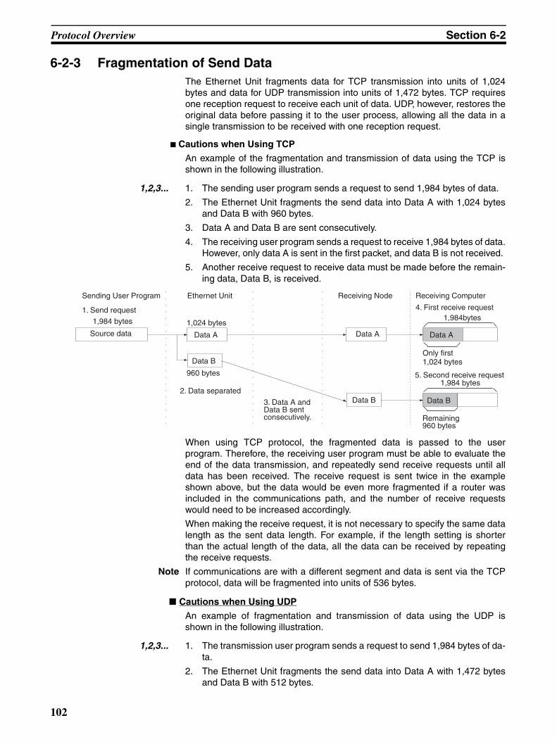
Protocol Overview Section 6-2
6-2-3 Fragmentation of Send DataThe Ethernet Unit fragments data for TCP transmission into units of 1,024bytes and data for UDP transmission into units of 1,472 bytes. TCP requiresone reception request to receive each unit of data. UDP, however, restores theoriginal data before passing it to the user process, allowing all the data in asingle transmission to be received with one reception request.
Cautions when Using TCP
An example of the fragmentation and transmission of data using the TCP isshown in the following illustration.
1,2,3... 1. The sending user program sends a request to send 1,984 bytes of data.
2. The Ethernet Unit fragments the send data into Data A with 1,024 bytesand Data B with 960 bytes.
3. Data A and Data B are sent consecutively.
4. The receiving user program sends a request to receive 1,984 bytes of data.However, only data A is sent in the first packet, and data B is not received.
5. Another receive request to receive data must be made before the remain-ing data, Data B, is received.
When using TCP protocol, the fragmented data is passed to the userprogram. Therefore, the receiving user program must be able to evaluate theend of the data transmission, and repeatedly send receive requests until alldata has been received. The receive request is sent twice in the exampleshown above, but the data would be even more fragmented if a router wasincluded in the communications path, and the number of receive requestswould need to be increased accordingly.
When making the receive request, it is not necessary to specify the same datalength as the sent data length. For example, if the length setting is shorterthan the actual length of the data, all the data can be received by repeatingthe receive requests.
Note If communications are with a different segment and data is sent via the TCPprotocol, data will be fragmented into units of 536 bytes.
Cautions when Using UDP
An example of fragmentation and transmission of data using the UDP isshown in the following illustration.
1,2,3... 1. The transmission user program sends a request to send 1,984 bytes of da-ta.
2. The Ethernet Unit fragments the send data into Data A with 1,472 bytesand Data B with 512 bytes.
Data B
Sending User Program Ethernet Unit
1. Send request
Source data
1,984 bytes 1,024 bytes
Data A
Data B
960 bytes
Data A
Data B
Data A
2. Data separated
3. Data A and Data B sent consecutively.
Receiving Node Receiving Computer
4. First receive request1,984bytes
1,984 bytes
Remaining 960 bytes
5. Second receive request
Only first 1,024 bytes
102
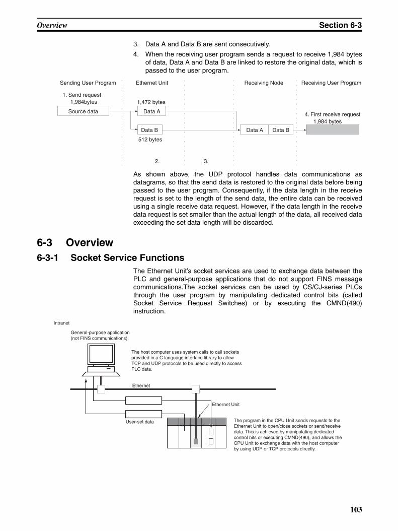
Overview Section 6-3
3. Data A and Data B are sent consecutively.
4. When the receiving user program sends a request to receive 1,984 bytesof data, Data A and Data B are linked to restore the original data, which ispassed to the user program.
As shown above, the UDP protocol handles data communications asdatagrams, so that the send data is restored to the original data before beingpassed to the user program. Consequently, if the data length in the receiverequest is set to the length of the send data, the entire data can be receivedusing a single receive data request. However, if the data length in the receivedata request is set smaller than the actual length of the data, all received dataexceeding the set data length will be discarded.
6-3 Overview6-3-1 Socket Service Functions
The Ethernet Unit’s socket services are used to exchange data between thePLC and general-purpose applications that do not support FINS messagecommunications.The socket services can be used by CS/CJ-series PLCsthrough the user program by manipulating dedicated control bits (calledSocket Service Request Switches) or by executing the CMND(490)instruction.
Source data
1,984bytes
Sending User Program
1. Send request
Data A
Data B
1,472 bytes
512 bytes
Ethernet Unit Receiving Node Receiving User Program
4. First receive request1,984 bytes
Data A Data B
3. 2.
Ethernet Unit
Ethernet
Intranet
User-set data
General-purpose application (not FINS communications);
The host computer uses system calls to call sockets provided in a C language interface library to allow TCP and UDP protocols to be used directly to access PLC data.
The program in the CPU Unit sends requests to the Ethernet Unit to open/close sockets or send/receive data. This is achieved by manipulating dedicated control bits or executing CMND(490), and allows the CPU Unit to exchange data with the host computer by using UDP or TCP protocols directly.
103
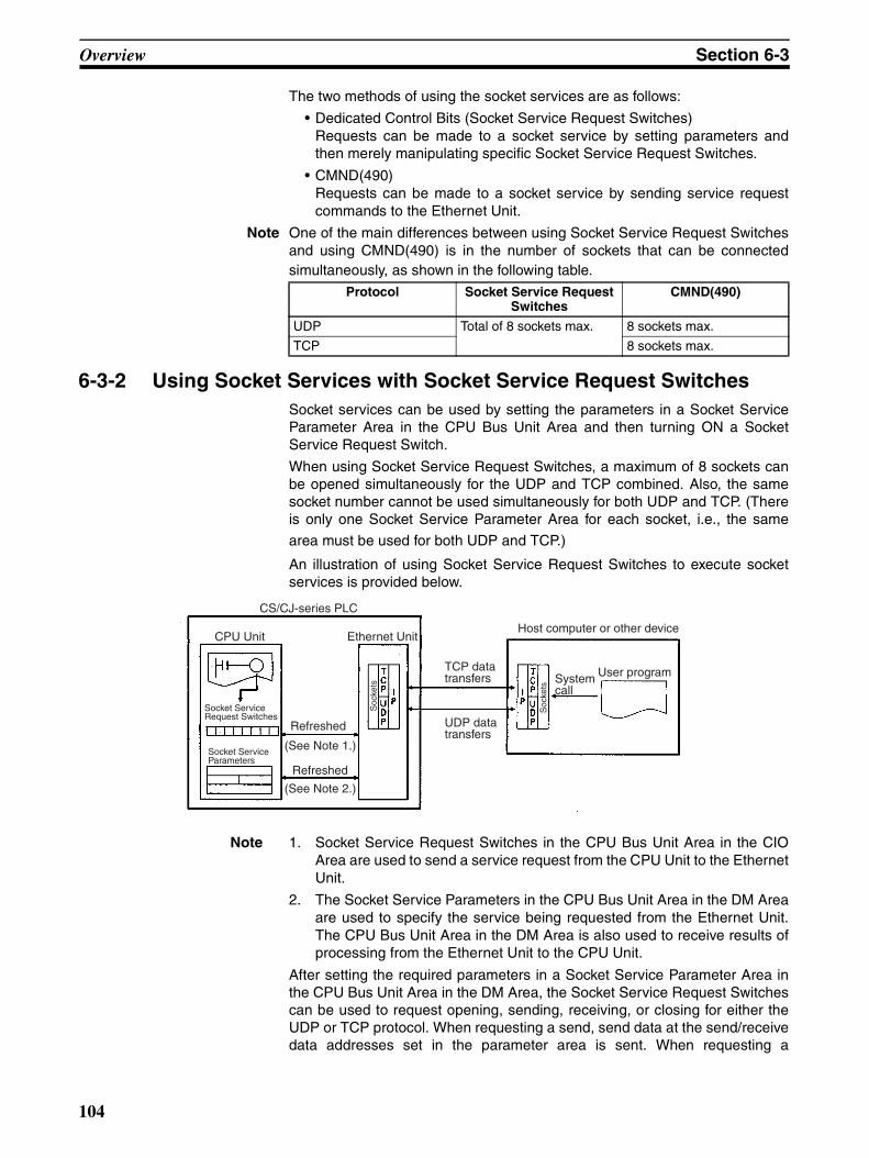
Overview Section 6-3
The two methods of using the socket services are as follows:
• Dedicated Control Bits (Socket Service Request Switches)Requests can be made to a socket service by setting parameters andthen merely manipulating specific Socket Service Request Switches.
• CMND(490)Requests can be made to a socket service by sending service requestcommands to the Ethernet Unit.
Note One of the main differences between using Socket Service Request Switchesand using CMND(490) is in the number of sockets that can be connectedsimultaneously, as shown in the following table.
6-3-2 Using Socket Services with Socket Service Request SwitchesSocket services can be used by setting the parameters in a Socket ServiceParameter Area in the CPU Bus Unit Area and then turning ON a SocketService Request Switch.
When using Socket Service Request Switches, a maximum of 8 sockets canbe opened simultaneously for the UDP and TCP combined. Also, the samesocket number cannot be used simultaneously for both UDP and TCP. (Thereis only one Socket Service Parameter Area for each socket, i.e., the same
area must be used for both UDP and TCP.)
An illustration of using Socket Service Request Switches to execute socketservices is provided below.
Note 1. Socket Service Request Switches in the CPU Bus Unit Area in the CIOArea are used to send a service request from the CPU Unit to the EthernetUnit.
2. The Socket Service Parameters in the CPU Bus Unit Area in the DM Areaare used to specify the service being requested from the Ethernet Unit.The CPU Bus Unit Area in the DM Area is also used to receive results ofprocessing from the Ethernet Unit to the CPU Unit.
After setting the required parameters in a Socket Service Parameter Area inthe CPU Bus Unit Area in the DM Area, the Socket Service Request Switchescan be used to request opening, sending, receiving, or closing for either theUDP or TCP protocol. When requesting a send, send data at the send/receivedata addresses set in the parameter area is sent. When requesting a
Protocol Socket Service Request Switches
CMND(490)
UDP Total of 8 sockets max. 8 sockets max.
TCP 8 sockets max.
CS/CJ-series PLC
CPU Unit Ethernet Unit
Socket Service Request Switches
Socket Service Parameters
Refreshed
(See Note 1.)
Refreshed
(See Note 2.)
TCP data transfers
UDP data transfers
Host computer or other device
System call
User program
Soc
kets
Soc
kets
104
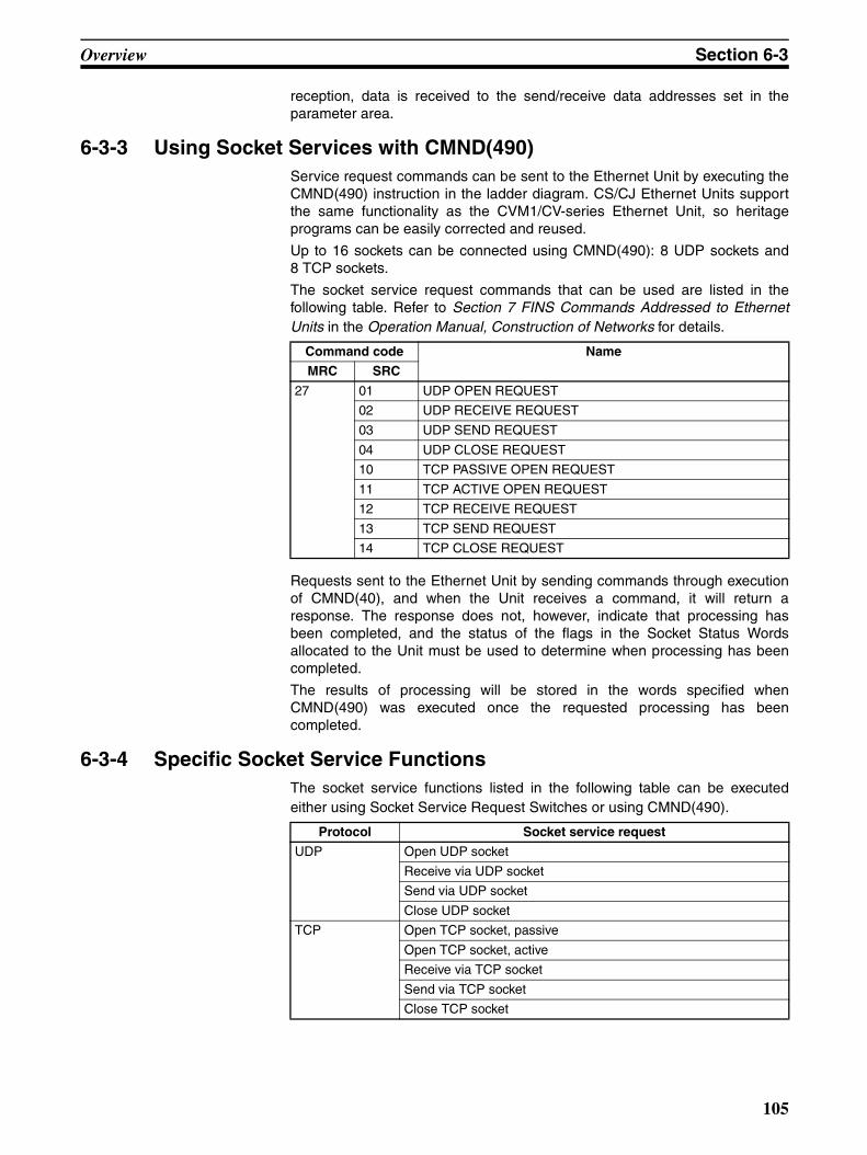
Overview Section 6-3
reception, data is received to the send/receive data addresses set in theparameter area.
6-3-3 Using Socket Services with CMND(490)Service request commands can be sent to the Ethernet Unit by executing theCMND(490) instruction in the ladder diagram. CS/CJ Ethernet Units supportthe same functionality as the CVM1/CV-series Ethernet Unit, so heritageprograms can be easily corrected and reused.
Up to 16 sockets can be connected using CMND(490): 8 UDP sockets and8 TCP sockets.
The socket service request commands that can be used are listed in thefollowing table. Refer to Section 7 FINS Commands Addressed to EthernetUnits in the Operation Manual, Construction of Networks for details.
Requests sent to the Ethernet Unit by sending commands through executionof CMND(40), and when the Unit receives a command, it will return aresponse. The response does not, however, indicate that processing hasbeen completed, and the status of the flags in the Socket Status Wordsallocated to the Unit must be used to determine when processing has beencompleted.
The results of processing will be stored in the words specified whenCMND(490) was executed once the requested processing has beencompleted.
6-3-4 Specific Socket Service FunctionsThe socket service functions listed in the following table can be executedeither using Socket Service Request Switches or using CMND(490).
Command code Name
MRC SRC
27 01 UDP OPEN REQUEST
02 UDP RECEIVE REQUEST
03 UDP SEND REQUEST
04 UDP CLOSE REQUEST
10 TCP PASSIVE OPEN REQUEST
11 TCP ACTIVE OPEN REQUEST
12 TCP RECEIVE REQUEST
13 TCP SEND REQUEST
14 TCP CLOSE REQUEST
Protocol Socket service request
UDP Open UDP socket
Receive via UDP socket
Send via UDP socket
Close UDP socket
TCP Open TCP socket, passive
Open TCP socket, active
Receive via TCP socket
Send via TCP socket
Close TCP socket
105
Socket Service Function Guide Section 6-4
6-3-5 Differences with Previous ModelsCompared with the socket service functions of previous models (CS1W-ETN01/11 and CJ1W-ETN11 Ethernet Units), the Number of Bytes Receivedat the TCP Socket that stores the size of received data accumulated in thereception buffer and a related Data Received Flag have been added. Thesenew features eliminate the need for ladder programs to monitor the timing forcompletion of instructions and socket service processing, and thus reduce theamount of labor required for program development.
6-4 Socket Service Function Guide
6-4-1 Manipulating Dedicated Control Bits Description
The Ethernet Unit's socket services are used by setting parameters andmanipulating bits only.
Point
This method is used by setting the required parameters in the socket serviceparameter area allocated in the CPU Bus Unit words in the DM Area, and thenturning ON the Socket Service Request Switches in memory.
Advantages/Disadvantages
A total of eight ports (UDP and TCP combined) can be used for socket ser-vices.
6-4-2 Executing CMND(490) Description
The socket services are used by sending service request commands to theEthernet Unit.
Point
A UDP or TCP socket service is requested by sending a FINS command tothe Ethernet Unit by executing CMND(490) from the CPU Unit.
Advantages/Disadvantages
• Knowledge of FINS commands is required.
• The previous user program can be used without changing because thefunctions are equivalent to those of CVM1/CV-series Ethernet Units.
• A total of 16 sockets, comprising eight TCP ports and eight UDP ports,can be used.
106
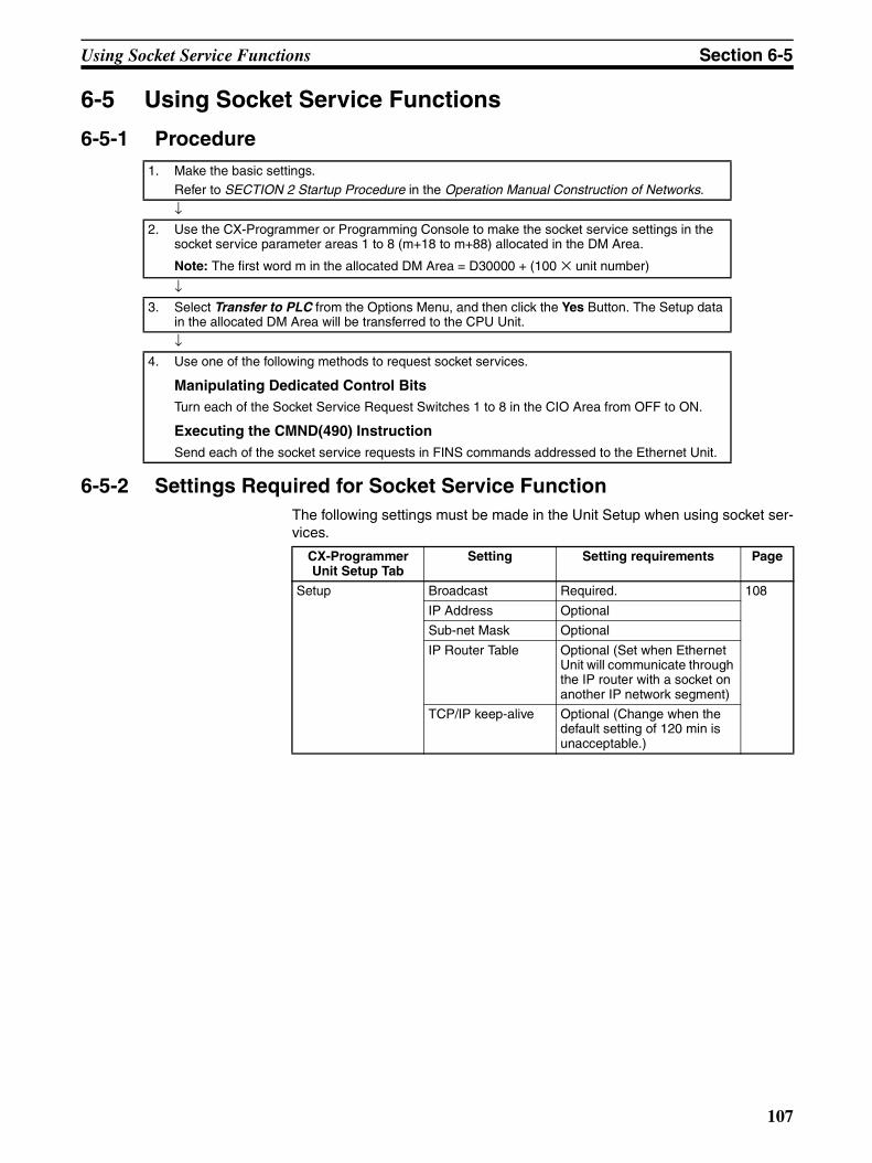
Using Socket Service Functions Section 6-5
6-5 Using Socket Service Functions
6-5-1 Procedure
6-5-2 Settings Required for Socket Service FunctionThe following settings must be made in the Unit Setup when using socket ser-vices.
1. Make the basic settings.Refer to SECTION 2 Startup Procedure in the Operation Manual Construction of Networks.
↓2. Use the CX-Programmer or Programming Console to make the socket service settings in the
socket service parameter areas 1 to 8 (m+18 to m+88) allocated in the DM Area.
Note: The first word m in the allocated DM Area = D30000 + (100 × unit number)
↓3. Select Transfer to PLC from the Options Menu, and then click the Yes Button. The Setup data
in the allocated DM Area will be transferred to the CPU Unit.
↓4. Use one of the following methods to request socket services.
Manipulating Dedicated Control BitsTurn each of the Socket Service Request Switches 1 to 8 in the CIO Area from OFF to ON.
Executing the CMND(490) InstructionSend each of the socket service requests in FINS commands addressed to the Ethernet Unit.
CX-Programmer Unit Setup Tab
Setting Setting requirements Page
Setup Broadcast Required. 108
IP Address Optional
Sub-net Mask Optional
IP Router Table Optional (Set when Ethernet Unit will communicate through the IP router with a socket on another IP network segment)
TCP/IP keep-alive Optional (Change when the default setting of 120 min is unacceptable.)
107
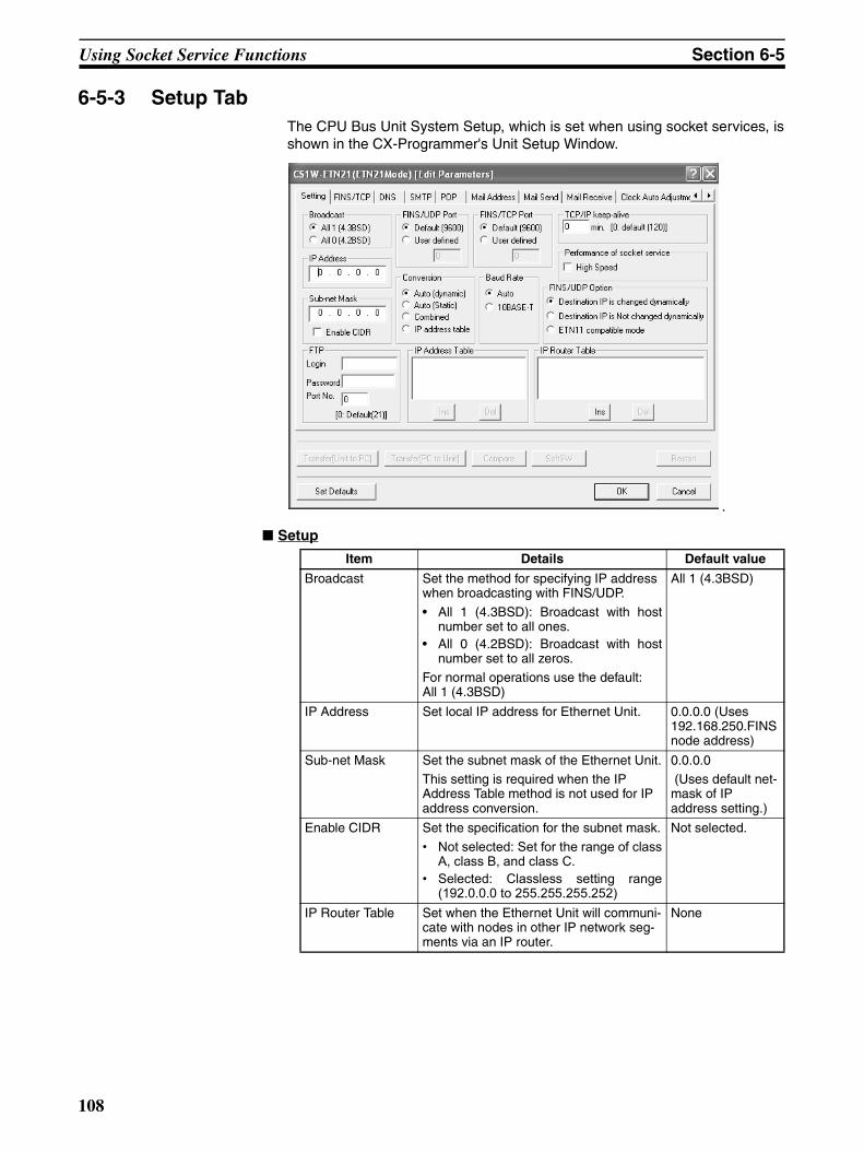
Using Socket Service Functions Section 6-5
6-5-3 Setup TabThe CPU Bus Unit System Setup, which is set when using socket services, isshown in the CX-Programmer's Unit Setup Window.
.
Setup
Item Details Default value
Broadcast Set the method for specifying IP address when broadcasting with FINS/UDP.
• All 1 (4.3BSD): Broadcast with hostnumber set to all ones.
• All 0 (4.2BSD): Broadcast with hostnumber set to all zeros.
For normal operations use the default:All 1 (4.3BSD)
All 1 (4.3BSD)
IP Address Set local IP address for Ethernet Unit. 0.0.0.0 (Uses 192.168.250.FINS node address)
Sub-net Mask Set the subnet mask of the Ethernet Unit.This setting is required when the IP Address Table method is not used for IP address conversion.
0.0.0.0 (Uses default net-mask of IP address setting.)
Enable CIDR Set the specification for the subnet mask.
• Not selected: Set for the range of classA, class B, and class C.
• Selected: Classless setting range(192.0.0.0 to 255.255.255.252)
Not selected.
IP Router Table Set when the Ethernet Unit will communi-cate with nodes in other IP network seg-ments via an IP router.
None
108
Using Socket Service Functions Section 6-5
TCP/IP keep-alive Set the liveness checking interval (keep-alive). When using FINS/TCP or TCP/IP socket services, if the remote node (server or client) continues idling (no response) for the duration of time set here or longer, the connection will be closed. (only when using FINS/TCP or TCP/IP socket services).
Setting range: 0 to 65535 minThe keep-alive setting (remote node live-ness checking enabled/disabled) is shared by each connection number set in the FINS/TCP Tab.
0(120 min)
High-speed Socket Services
Selecting this option improves the perfor-mance of processing for sending and receiving using specific bits for socket services. For information on communica-tions performance, refer to 6-9-5 Times Required for Sending and Receiving for Socket Services in the Ethernet Units Construction of Applications Operation Manual. When the High-speed Option is selected, socket services using a CMND(490) instruction will cause an error.
Not selected.
Item Details Default value
109
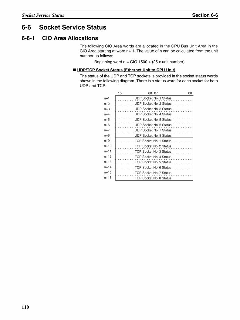
Socket Service Status Section 6-6
6-6 Socket Service Status
6-6-1 CIO Area AllocationsThe following CIO Area words are allocated in the CPU Bus Unit Area in theCIO Area starting at word n+ 1. The value of n can be calculated from the unitnumber as follows:
Beginning word n = CIO 1500 + (25 x unit number)
UDP/TCP Socket Status (Ethernet Unit to CPU Unit)
The status of the UDP and TCP sockets is provided in the socket status wordsshown in the following diagram. There is a status word for each socket for bothUDP and TCP.
UDP Socket No. 1 Status
TCP Socket No. 1 Status
TCP Socket No. 2 Status
TCP Socket No. 3 Status
TCP Socket No. 4 Status
TCP Socket No. 5 Status
TCP Socket No. 6 Status
TCP Socket No. 7 Status
TCP Socket No. 8 Status
UDP Socket No. 2 Status
UDP Socket No. 3 Status
UDP Socket No. 4 Status
UDP Socket No. 5 Status
UDP Socket No. 6 Status
UDP Socket No. 7 Status
UDP Socket No. 8 Status
n+1
n+2
n+3
n+4
n+5
n+6
n+7
n+8
n+9
n+10
n+11
n+12
n+13
n+14
n+15
n+16
15 08 07 00
110
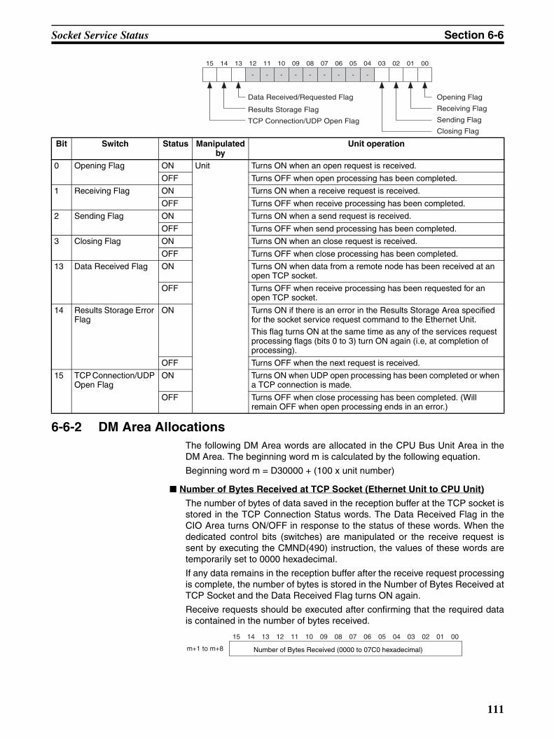
Socket Service Status Section 6-6
6-6-2 DM Area AllocationsThe following DM Area words are allocated in the CPU Bus Unit Area in theDM Area. The beginning word m is calculated by the following equation.
Beginning word m = D30000 + (100 x unit number)
Number of Bytes Received at TCP Socket (Ethernet Unit to CPU Unit)
The number of bytes of data saved in the reception buffer at the TCP socket isstored in the TCP Connection Status words. The Data Received Flag in theCIO Area turns ON/OFF in response to the status of these words. When thededicated control bits (switches) are manipulated or the receive request issent by executing the CMND(490) instruction, the values of these words aretemporarily set to 0000 hexadecimal.
If any data remains in the reception buffer after the receive request processingis complete, the number of bytes is stored in the Number of Bytes Received atTCP Socket and the Data Received Flag turns ON again.
Receive requests should be executed after confirming that the required datais contained in the number of bytes received.
15 14 13 12 10 09 08 07 06 05 04 03 02 01 0011
- - - - - - - - -
Data Received/Requested Flag
Receiving Flag
Sending Flag
Closing Flag
Opening Flag
Results Storage Flag
TCP Connection/UDP Open Flag
Bit Switch Status Manipulated by
Unit operation
0 Opening Flag ON Unit Turns ON when an open request is received.
OFF Turns OFF when open processing has been completed.
1 Receiving Flag ON Turns ON when a receive request is received.
OFF Turns OFF when receive processing has been completed.
2 Sending Flag ON Turns ON when a send request is received.
OFF Turns OFF when send processing has been completed.
3 Closing Flag ON Turns ON when an close request is received.
OFF Turns OFF when close processing has been completed.
13 Data Received Flag ON Turns ON when data from a remote node has been received at an open TCP socket.
OFF Turns OFF when receive processing has been requested for an open TCP socket.
14 Results Storage Error Flag
ON Turns ON if there is an error in the Results Storage Area specified for the socket service request command to the Ethernet Unit.This flag turns ON at the same time as any of the services request processing flags (bits 0 to 3) turn ON again (i.e, at completion of processing).
OFF Turns OFF when the next request is received.
15 TCP Connection/UDP Open Flag
ON Turns ON when UDP open processing has been completed or when a TCP connection is made.
OFF Turns OFF when close processing has been completed. (Will remain OFF when open processing ends in an error.)
15 14 13 12 10 09 08 07 06 05 04 03 02 01 0011
m+1 to m+8 Number of Bytes Received (0000 to 07C0 hexadecimal)
111
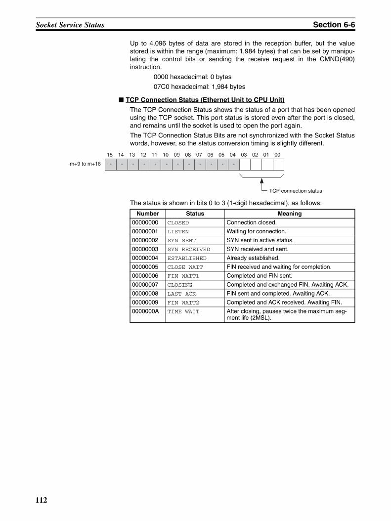
Socket Service Status Section 6-6
Up to 4,096 bytes of data are stored in the reception buffer, but the valuestored is within the range (maximum: 1,984 bytes) that can be set by manipu-lating the control bits or sending the receive request in the CMND(490)instruction.
0000 hexadecimal: 0 bytes
07C0 hexadecimal: 1,984 bytes
TCP Connection Status (Ethernet Unit to CPU Unit)
The TCP Connection Status shows the status of a port that has been openedusing the TCP socket. This port status is stored even after the port is closed,and remains until the socket is used to open the port again.
The TCP Connection Status Bits are not synchronized with the Socket Statuswords, however, so the status conversion timing is slightly different.
The status is shown in bits 0 to 3 (1-digit hexadecimal), as follows:
15 14 13 12 10 09 08 07 06 05 04 03 02 01 0011
m+9 to m+16
TCP connection status
- - - - - - - - - - - -
Number Status Meaning
00000000 CLOSED Connection closed.
00000001 LISTEN Waiting for connection.
00000002 SYN SENT SYN sent in active status.
00000003 SYN RECEIVED SYN received and sent.
00000004 ESTABLISHED Already established.
00000005 CLOSE WAIT FIN received and waiting for completion.
00000006 FIN WAIT1 Completed and FIN sent.
00000007 CLOSING Completed and exchanged FIN. Awaiting ACK.
00000008 LAST ACK FIN sent and completed. Awaiting ACK.
00000009 FIN WAIT2 Completed and ACK received. Awaiting FIN.
0000000A TIME WAIT After closing, pauses twice the maximum seg-ment life (2MSL).
112
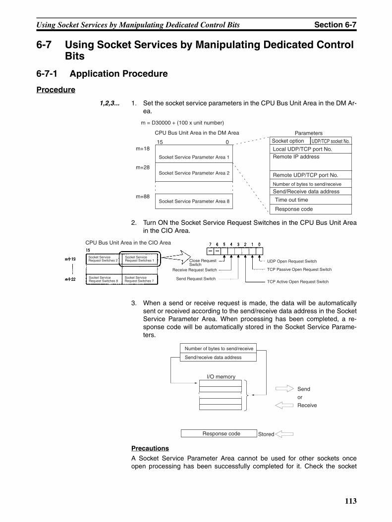
Using Socket Services by Manipulating Dedicated Control Bits Section 6-7
6-7 Using Socket Services by Manipulating Dedicated Control Bits
6-7-1 Application Procedure
Procedure
1,2,3... 1. Set the socket service parameters in the CPU Bus Unit Area in the DM Ar-ea.
2. Turn ON the Socket Service Request Switches in the CPU Bus Unit Areain the CIO Area.
3. When a send or receive request is made, the data will be automaticallysent or received according to the send/receive data address in the SocketService Parameter Area. When processing has been completed, a re-sponse code will be automatically stored in the Socket Service Parame-ters.
Precautions
A Socket Service Parameter Area cannot be used for other sockets onceopen processing has been successfully completed for it. Check the socket
Remote UDP/TCP port No.
Number of bytes to send/receive
Send/Receive data address
Parameters
m = D30000 + (100 x unit number)
CPU Bus Unit Area in the DM Area
Socket Service Parameter Area 1
Socket Service Parameter Area 8
Socket Service Parameter Area 2
Time out time
Response code
UDP/TCP socket No.
Local UDP/TCP port No.Remote IP address
15 0m+18
m+28
m+88
Socket option
Socket Service Request Switches 7
Socket Service Request Switches 1
Socket Service Request Switches 8
Socket Service Request Switches 2
CPU Bus Unit Area in the CIO Area
Close Request Switch
Receive Request Switch
Send Request Switch
UDP Open Request Switch
TCP Passive Open Request Switch
TCP Active Open Request Switch
Number of bytes to send/receive
Send/receive data address
I/O memory
Send
or
Receive
Response code Stored
113
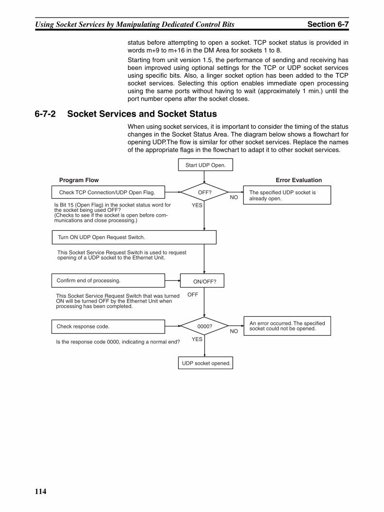
Using Socket Services by Manipulating Dedicated Control Bits Section 6-7
status before attempting to open a socket. TCP socket status is provided inwords m+9 to m+16 in the DM Area for sockets 1 to 8.
Starting from unit version 1.5, the performance of sending and receiving hasbeen improved using optional settings for the TCP or UDP socket servicesusing specific bits. Also, a linger socket option has been added to the TCPsocket services. Selecting this option enables immediate open processingusing the same ports without having to wait (approximately 1 min.) until theport number opens after the socket closes.
6-7-2 Socket Services and Socket StatusWhen using socket services, it is important to consider the timing of the statuschanges in the Socket Status Area. The diagram below shows a flowchart foropening UDP.The flow is similar for other socket services. Replace the namesof the appropriate flags in the flowchart to adapt it to other socket services.
Check TCP Connection/UDP Open Flag. The specified UDP socket is already open.
Turn ON UDP Open Request Switch.
Start UDP Open.
OFF?
Program Flow
Is Bit 15 (Open Flag) in the socket status word for the socket being used OFF? (Checks to see if the socket is open before com-munications and close processing.)
YES
Error Evaluation
UDP socket opened.
NO
This Socket Service Request Switch is used to request opening of a UDP socket to the Ethernet Unit.
Confirm end of processing.
0000?
YES
NO
ON/OFF?
OFFThis Socket Service Request Switch that was turned ON will be turned OFF by the Ethernet Unit when processing has been completed.
Check response code.
Is the response code 0000, indicating a normal end?
An error occurred. The specified socket could not be opened.
114
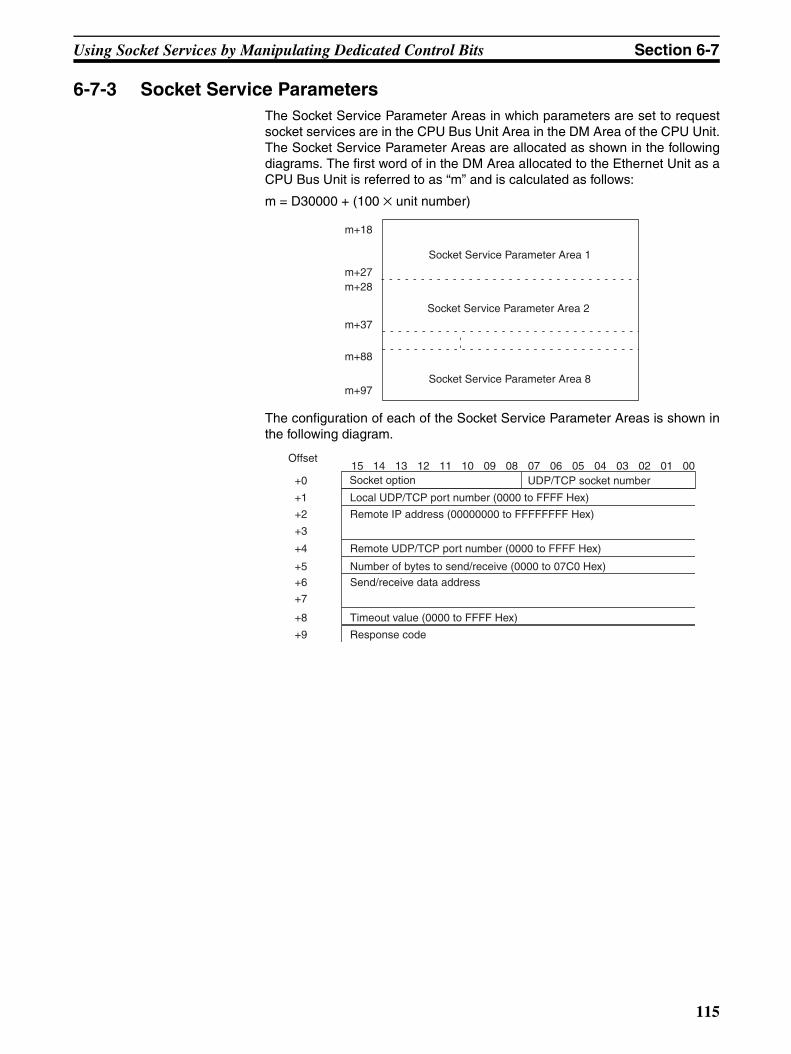
Using Socket Services by Manipulating Dedicated Control Bits Section 6-7
6-7-3 Socket Service ParametersThe Socket Service Parameter Areas in which parameters are set to requestsocket services are in the CPU Bus Unit Area in the DM Area of the CPU Unit.The Socket Service Parameter Areas are allocated as shown in the followingdiagrams. The first word of in the DM Area allocated to the Ethernet Unit as aCPU Bus Unit is referred to as “m” and is calculated as follows:
m = D30000 + (100 × unit number)
The configuration of each of the Socket Service Parameter Areas is shown inthe following diagram.
Socket Service Parameter Area 1
Socket Service Parameter Area 8
Socket Service Parameter Area 2
m+18
m+27m+28
m+37
m+88
m+97
Offset
UDP/TCP socket number
Local UDP/TCP port number (0000 to FFFF Hex)
Remote IP address (00000000 to FFFFFFFF Hex)
Number of bytes to send/receive (0000 to 07C0 Hex)
Send/receive data address
Timeout value (0000 to FFFF Hex)
Response code
Remote UDP/TCP port number (0000 to FFFF Hex)
15 14 13 12 11 10 09 08 07 06 05 04 03 02 01 00+0
+1
+2
+3
+4
+5
+6
+7
+8
+9
Socket option
115
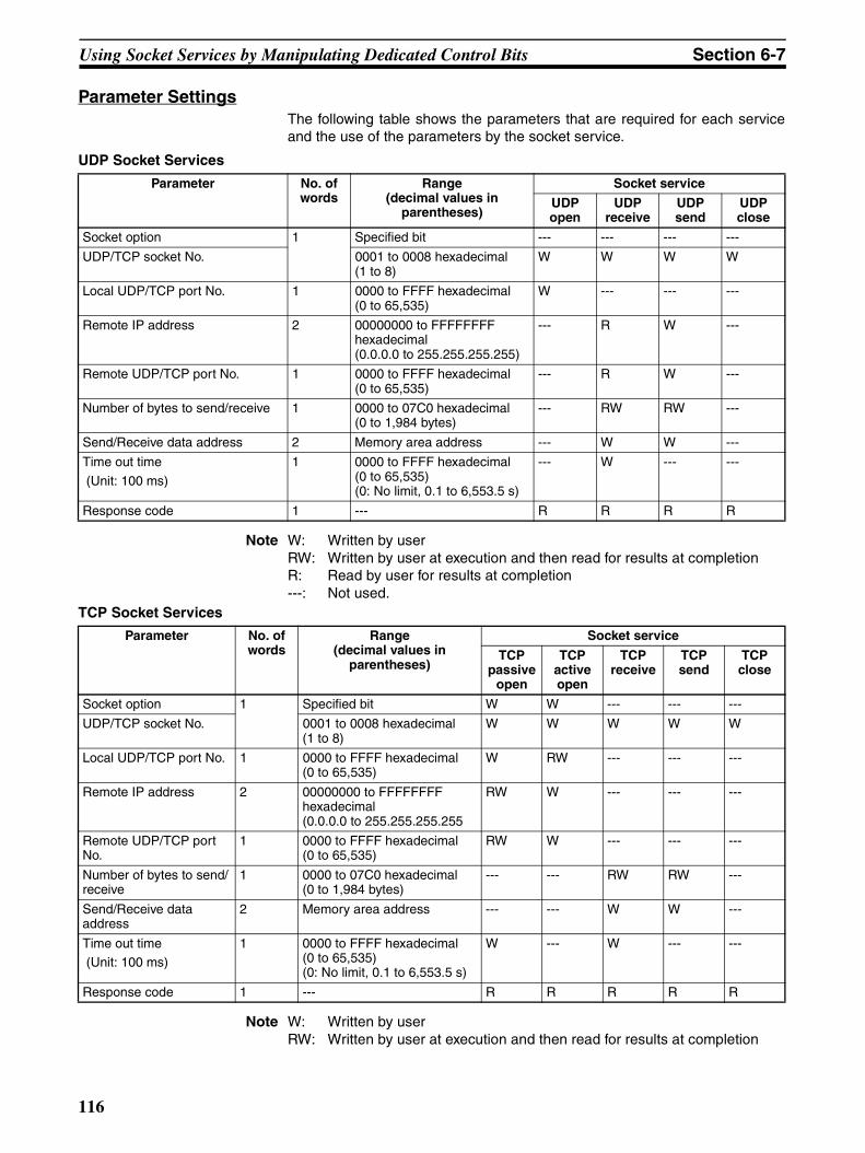
Using Socket Services by Manipulating Dedicated Control Bits Section 6-7
Parameter SettingsThe following table shows the parameters that are required for each serviceand the use of the parameters by the socket service.
UDP Socket Services
Note W: Written by userRW: Written by user at execution and then read for results at completionR: Read by user for results at completion---: Not used.
TCP Socket Services
Note W: Written by userRW: Written by user at execution and then read for results at completion
Parameter No. of words
Range (decimal values in
parentheses)
Socket service
UDP open
UDP receive
UDP send
UDP close
Socket option 1 Specified bit --- --- --- ---
UDP/TCP socket No. 0001 to 0008 hexadecimal(1 to 8)
W W W W
Local UDP/TCP port No. 1 0000 to FFFF hexadecimal(0 to 65,535)
W --- --- ---
Remote IP address 2 00000000 to FFFFFFFF hexadecimal (0.0.0.0 to 255.255.255.255)
--- R W ---
Remote UDP/TCP port No. 1 0000 to FFFF hexadecimal(0 to 65,535)
--- R W ---
Number of bytes to send/receive 1 0000 to 07C0 hexadecimal(0 to 1,984 bytes)
--- RW RW ---
Send/Receive data address 2 Memory area address --- W W ---
Time out time
(Unit: 100 ms)
1 0000 to FFFF hexadecimal(0 to 65,535)(0: No limit, 0.1 to 6,553.5 s)
--- W --- ---
Response code 1 --- R R R R
Parameter No. of words
Range (decimal values in
parentheses)
Socket service
TCP passive
open
TCP active open
TCP receive
TCP send
TCP close
Socket option 1 Specified bit W W --- --- ---
UDP/TCP socket No. 0001 to 0008 hexadecimal (1 to 8)
W W W W W
Local UDP/TCP port No. 1 0000 to FFFF hexadecimal (0 to 65,535)
W RW --- --- ---
Remote IP address 2 00000000 to FFFFFFFF hexadecimal (0.0.0.0 to 255.255.255.255
RW W --- --- ---
Remote UDP/TCP port No.
1 0000 to FFFF hexadecimal (0 to 65,535)
RW W --- --- ---
Number of bytes to send/receive
1 0000 to 07C0 hexadecimal (0 to 1,984 bytes)
--- --- RW RW ---
Send/Receive data address
2 Memory area address --- --- W W ---
Time out time (Unit: 100 ms)
1 0000 to FFFF hexadecimal (0 to 65,535)(0: No limit, 0.1 to 6,553.5 s)
W --- W --- ---
Response code 1 --- R R R R R
116
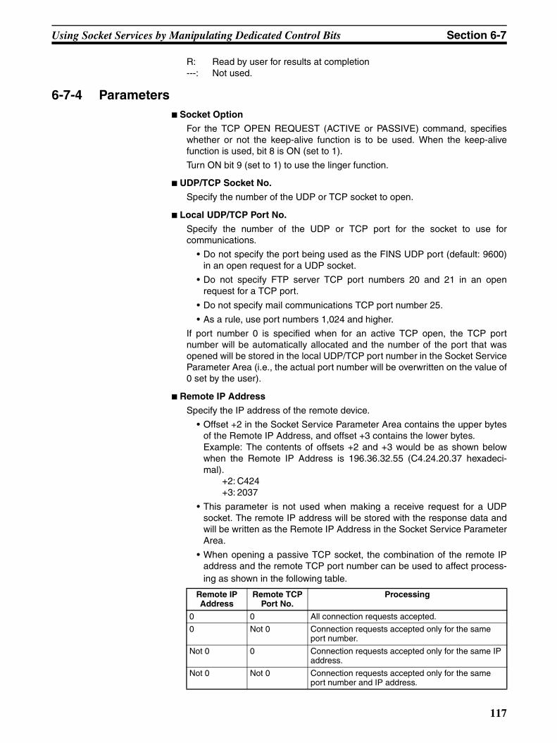
Using Socket Services by Manipulating Dedicated Control Bits Section 6-7
R: Read by user for results at completion---: Not used.
6-7-4 Parameters Socket Option
For the TCP OPEN REQUEST (ACTIVE or PASSIVE) command, specifieswhether or not the keep-alive function is to be used. When the keep-alivefunction is used, bit 8 is ON (set to 1).
Turn ON bit 9 (set to 1) to use the linger function.
UDP/TCP Socket No.
Specify the number of the UDP or TCP socket to open.
Local UDP/TCP Port No.
Specify the number of the UDP or TCP port for the socket to use forcommunications.
• Do not specify the port being used as the FINS UDP port (default: 9600)in an open request for a UDP socket.
• Do not specify FTP server TCP port numbers 20 and 21 in an openrequest for a TCP port.
• Do not specify mail communications TCP port number 25.
• As a rule, use port numbers 1,024 and higher.
If port number 0 is specified when for an active TCP open, the TCP portnumber will be automatically allocated and the number of the port that wasopened will be stored in the local UDP/TCP port number in the Socket ServiceParameter Area (i.e., the actual port number will be overwritten on the value of0 set by the user).
Remote IP Address
Specify the IP address of the remote device.
• Offset +2 in the Socket Service Parameter Area contains the upper bytesof the Remote IP Address, and offset +3 contains the lower bytes.Example: The contents of offsets +2 and +3 would be as shown belowwhen the Remote IP Address is 196.36.32.55 (C4.24.20.37 hexadeci-mal).
+2: C424+3: 2037
• This parameter is not used when making a receive request for a UDPsocket. The remote IP address will be stored with the response data andwill be written as the Remote IP Address in the Socket Service ParameterArea.
• When opening a passive TCP socket, the combination of the remote IPaddress and the remote TCP port number can be used to affect process-ing as shown in the following table.
Remote IP Address
Remote TCP Port No.
Processing
0 0 All connection requests accepted.
0 Not 0 Connection requests accepted only for the same port number.
Not 0 0 Connection requests accepted only for the same IP address.
Not 0 Not 0 Connection requests accepted only for the same port number and IP address.
117
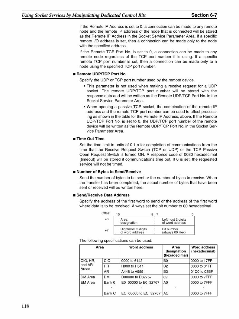
Using Socket Services by Manipulating Dedicated Control Bits Section 6-7
If the Remote IP Address is set to 0, a connection can be made to any remotenode and the remote IP address of the node that is connected will be storedas the Remote IP Address in the Socket Service Parameter Area. If a specificremote I/O address is set, then a connection can be made only to the nodewith the specified address.
If the Remote TCP Port No. is set to 0, a connection can be made to anyremote node regardless of the TCP port number it is using. If a specificremote TCP port number is set, then a connection can be made only to anode using the specified TCP port number.
Remote UDP/TCP Port No.
Specify the UDP or TCP port number used by the remote device.
• This parameter is not used when making a receive request for a UDPsocket. The remote UDP/TCP port number will be stored with theresponse data and will be written as the Remote UDP/TCP Port No. in theSocket Service Parameter Area.
• When opening a passive TCP socket, the combination of the remote IPaddress and the remote TCP port number can be used to affect process-ing as shown in the table for the Remote IP Address, above. If the RemoteUDP/TCP Port No. is set to 0, the UDP/TCP port number of the remotedevice will be written as the Remote UDP/TCP Port No. in the Socket Ser-vice Parameter Area.
Time Out Time
Set the time limit in units of 0.1 s for completion of communications from thetime that the Receive Request Switch (TCP or UDP) or the TCP PassiveOpen Request Switch is turned ON. A response code of 0080 hexadecimal(timeout) will be stored if communications time out. If 0 is set, the requestedservice will not be timed.
Number of Bytes to Send/Receive
Send the number of bytes to be sent or the number of bytes to receive. Whenthe transfer has been completed, the actual number of bytes that have beensent or received will be written here.
Send/Receive Data Address
Specify the address of the first word to send or the address of the first wordwhere data is to be received. Always set the bit number to 00 hexadecimal.
The following specifications can be used.
Area Word address Area designation
(hexadecimal)
Word address (hexadecimal)
CIO, HR, and AR Areas
CIO 0000 to 6143 B0 0000 to 17FF
HR H000 to H511 B2 0000 to 01FF
AR A448 to A959 B3 01C0 to 03BF
DM Area DM D00000 to D32767 82 0000 to 7FFF
EM Area Bank 0 E0_00000 to E0_32767 A0 0000 to 7FFF
: : : :
Bank C EC_00000 to EC_32767 AC 0000 to 7FFF
Offset
Area designation
Leftmost 2 digits of word address
Rightmost 2 digits of word address
Bit number (always 00 Hex)
15 8 7 0+6
+7
118
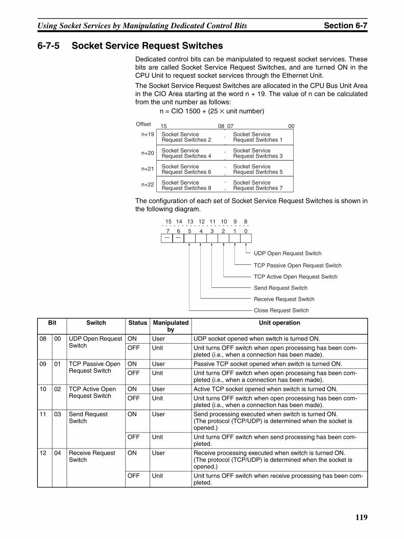
Using Socket Services by Manipulating Dedicated Control Bits Section 6-7
6-7-5 Socket Service Request SwitchesDedicated control bits can be manipulated to request socket services. Thesebits are called Socket Service Request Switches, and are turned ON in theCPU Unit to request socket services through the Ethernet Unit.
The Socket Service Request Switches are allocated in the CPU Bus Unit Areain the CIO Area starting at the word n + 19. The value of n can be calculatedfrom the unit number as follows:
n = CIO 1500 + (25 × unit number)
The configuration of each set of Socket Service Request Switches is shown inthe following diagram.
Socket Service Request Switches 7
Socket Service Request Switches 5
Socket Service Request Switches 3
Socket Service Request Switches 1
Socket Service Request Switches 8
Socket Service Request Switches 2
Socket Service Request Switches 4
Socket Service Request Switches 6
Offset 15 08 07 00
n+19
n+20
n+21
n+22
UDP Open Request Switch
TCP Passive Open Request Switch
TCP Active Open Request Switch
Send Request Switch
Receive Request Switch
Close Request Switch
7 6 5 4 3 2 1 0
15 14 13 12 11 10 9 8
Bit Switch Status Manipulated by
Unit operation
08 00 UDP Open Request Switch
ON User UDP socket opened when switch is turned ON.
OFF Unit Unit turns OFF switch when open processing has been com-pleted (i.e., when a connection has been made).
09 01 TCP Passive Open Request Switch
ON User Passive TCP socket opened when switch is turned ON.
OFF Unit Unit turns OFF switch when open processing has been com-pleted (i.e., when a connection has been made).
10 02 TCP Active Open Request Switch
ON User Active TCP socket opened when switch is turned ON.
OFF Unit Unit turns OFF switch when open processing has been com-pleted (i.e., when a connection has been made).
11 03 Send Request Switch
ON User Send processing executed when switch is turned ON. (The protocol (TCP/UDP) is determined when the socket is opened.)
OFF Unit Unit turns OFF switch when send processing has been com-pleted.
12 04 Receive Request Switch
ON User Receive processing executed when switch is turned ON. (The protocol (TCP/UDP) is determined when the socket is opened.)
OFF Unit Unit turns OFF switch when receive processing has been com-pleted.
119
Using Socket Services by Manipulating Dedicated Control Bits Section 6-7
As shown in the above table, the Request Switches are turned OFF by theEthernet Unit when the requested processes has been completed.
Note There is also a Socket Force-close Switch in bit 2 of the first word allocated tothe Ethernet Unit in the CPU Bus Unit Area in the CIO Area. When the SocketForce-close Switch is turned ON, all sockets that are open will be force-closed. Refer to Section 4 Ethernet Unit Memory Allocations in the OperationManual, Construction of Networks for details.
When using socket services with the Socket Service Request Switches, theladder diagram should be programmed to check the response codes whenSocket Service Request Switches are turned OFF.
6-7-6 Response CodesWhen processing of a request has been completed for socket services exe-cuted using Socket Service Request Switches, a response code will be storedin the Response Code word in the Socket Service Parameter Area. The fol-lowing response codes will be stored depending on the service that wasrequested.
UDP Socket Open Request
UDP Socket Receive Request
13 05 Close Request Switch
ON User Close processing executed when switch is turned ON. (The protocol (TCP/UDP) is determined when the socket is opened.)
OFF Unit Unit turns OFF switch when close processing has been com-pleted.
Bit Switch Status Manipulated by
Unit operation
Response code
Meaning
0000 Normal end
0105 Local IP address setting error.
0302 CPU Unit error; cannot execute.
1100 UDP socket number is not 1 to 8 or local UDP port number is 0.
110C Request Switch turned ON during other processing.
220F Specified socket is already open.
2211 Unit is busy; cannot execute.
2606 Specified socket is already open as TCP socket; cannot open UDP socket.
2607 Specified Socket Service Parameter Area is already being used for another socket.
003E Internal buffer cannot be obtained due to high reception traffic (ENOBUFS).
0049 The same UDP port number has been specified more than once (EADDRINUSE).
0081 The specified socket was closed during open processing.
Response code
Meaning
0000 Normal end
0302 CPU Unit error; cannot execute.
1100 Number of bytes to receive is not in allowable range.
1101 The area designation of the Send/Receive Data Address is not in allowable range.
120
Using Socket Services by Manipulating Dedicated Control Bits Section 6-7
UDP Socket Send Request
UDP Socket Close Request
1103 The bit number in the Send/Receive Data Address is not 00.
110C Request Switch turned ON during other processing.
220F Specified socket is already processing a receive request.
2210 The specified socket is not open.
2211 Unit is busy; cannot execute service.
2607 Specified Socket Service Parameter Area is already being used for another socket.
003E Internal buffer cannot be obtained due to high reception traffic (ENOBUFS).
0066 Internal memory cannot be obtained; cannot execute service.
0080 Receive request timed out.
0081 The specified socket was closed during reception processing.
Response code
Meaning
0000 Normal end
0302 CPU Unit error; cannot execute.
1100 Number of bytes to send is not in allowable range or the remote IP address is 0.
1101 The area designation of the Send/Receive Data Address is not in allowable range.
1103 The bit number in the Send/Receive Data Address is not 00.
110C Request Switch turned ON during other processing.
220F Specified socket is already processing a send request.
2210 The specified socket is not open.
2211 Unit is busy; cannot execute.
2607 Specified Socket Service Parameter Area is already being used for another socket.
003E Internal buffer cannot be obtained due to high reception traffic (ENOBUFS).
0042 The remote IP address is a broadcast address and the number of bytes to send is greater than 1,472 bytes (EMSGSIZE).
004C The network ID is incorrect or the remote IP address is incorrect (EADDRNOTAVAIL)
004E The network ID is not in the IP router table, router settings are incor-rect, or the remote IP address is incorrect (ENETUNREACH).
0051 The router settings are incorrect or the remote IP address is incor-rect (EHOSTUNREACH).
0081 The specified socket was closed during send processing.
Response code
Meaning
0000 Normal end
0302 CPU Unit error; cannot execute.
2210 The specified socket is not open.
2211 Unit is busy; cannot execute.
2607 Specified Socket Service Parameter Area is already being used for another socket.
Response code
Meaning
121
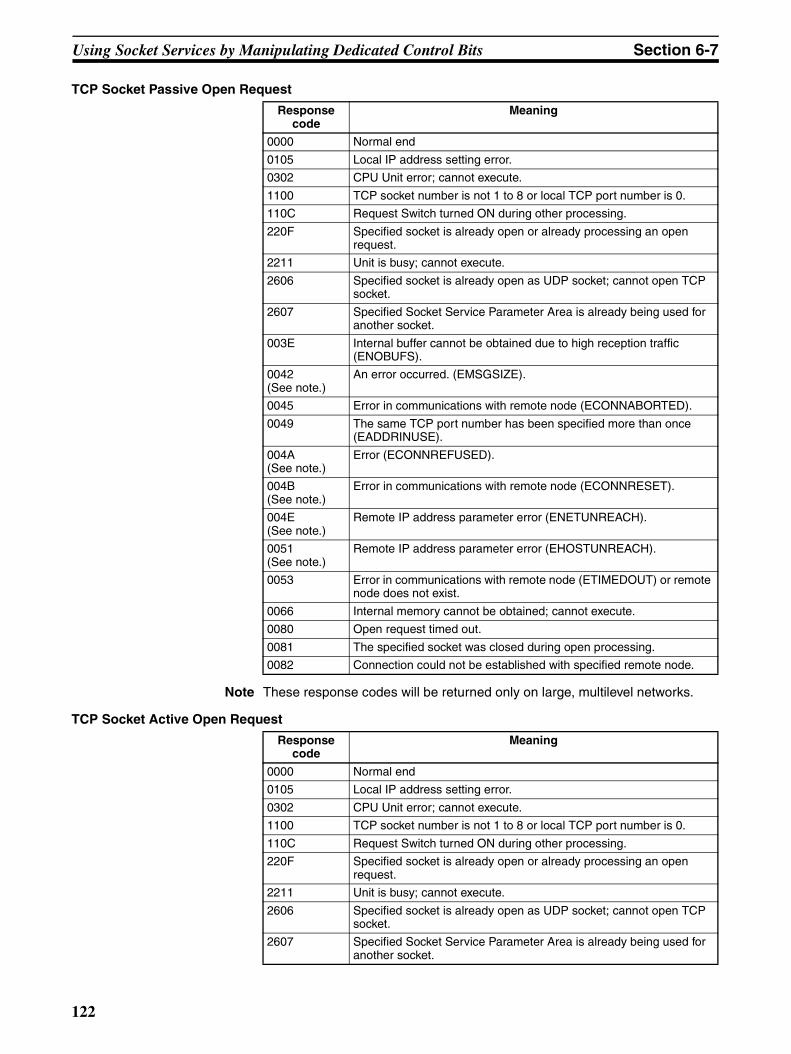
Using Socket Services by Manipulating Dedicated Control Bits Section 6-7
TCP Socket Passive Open Request
Note These response codes will be returned only on large, multilevel networks.
TCP Socket Active Open Request
Response code
Meaning
0000 Normal end
0105 Local IP address setting error.
0302 CPU Unit error; cannot execute.
1100 TCP socket number is not 1 to 8 or local TCP port number is 0.
110C Request Switch turned ON during other processing.
220F Specified socket is already open or already processing an open request.
2211 Unit is busy; cannot execute.
2606 Specified socket is already open as UDP socket; cannot open TCP socket.
2607 Specified Socket Service Parameter Area is already being used for another socket.
003E Internal buffer cannot be obtained due to high reception traffic (ENOBUFS).
0042 (See note.)
An error occurred. (EMSGSIZE).
0045 Error in communications with remote node (ECONNABORTED).
0049 The same TCP port number has been specified more than once (EADDRINUSE).
004A (See note.)
Error (ECONNREFUSED).
004B (See note.)
Error in communications with remote node (ECONNRESET).
004E (See note.)
Remote IP address parameter error (ENETUNREACH).
0051 (See note.)
Remote IP address parameter error (EHOSTUNREACH).
0053 Error in communications with remote node (ETIMEDOUT) or remote node does not exist.
0066 Internal memory cannot be obtained; cannot execute.
0080 Open request timed out.
0081 The specified socket was closed during open processing.
0082 Connection could not be established with specified remote node.
Response code
Meaning
0000 Normal end
0105 Local IP address setting error.
0302 CPU Unit error; cannot execute.
1100 TCP socket number is not 1 to 8 or local TCP port number is 0.
110C Request Switch turned ON during other processing.
220F Specified socket is already open or already processing an open request.
2211 Unit is busy; cannot execute.
2606 Specified socket is already open as UDP socket; cannot open TCP socket.
2607 Specified Socket Service Parameter Area is already being used for another socket.
122
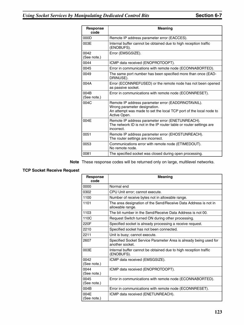
Using Socket Services by Manipulating Dedicated Control Bits Section 6-7
Note These response codes will be returned only on large, multilevel networks.
TCP Socket Receive Request
000D Remote IP address parameter error (EACCES).
003E Internal buffer cannot be obtained due to high reception traffic (ENOBUFS).
0042 (See note.)
Error (EMSGSIZE).
0044 ICMP data received (ENOPROTOOPT).
0045 Error in communications with remote node (ECONNABORTED).
0049 The same port number has been specified more than once (EAD-DRINUSE).
004A Error (ECONNREFUSED) or the remote node has not been opened as passive socket.
004B (See note.)
Error in communications with remote node (ECONNRESET).
004C Remote IP address parameter error (EADDRNOTAVAIL).Wrong parameter designation.An attempt was made to set the local TCP port of the local node to Active Open.
004E Remote IP address parameter error (ENETUNREACH).The network ID is not in the IP router table or router settings are incorrect.
0051 Remote IP address parameter error (EHOSTUNREACH).The router settings are incorrect.
0053 Communications error with remote node (ETIMEDOUT).No remote node.
0081 The specified socket was closed during open processing.
Response code
Meaning
0000 Normal end
0302 CPU Unit error; cannot execute.
1100 Number of receive bytes not in allowable range.
1101 The area designation of the Send/Receive Data Address is not in allowable range.
1103 The bit number in the Send/Receive Data Address is not 00.
110C Request Switch turned ON during other processing.
220F Specified socket is already processing a receive request.
2210 Specified socket has not been connected.
2211 Unit is busy; cannot execute.
2607 Specified Socket Service Parameter Area is already being used for another socket.
003E Internal buffer cannot be obtained due to high reception traffic (ENOBUFS).
0042 (See note.)
ICMP data received (EMSGSIZE).
0044 (See note.)
ICMP data received (ENOPROTOOPT).
0045 (See note.)
Error in communications with remote node (ECONNABORTED).
004B Error in communications with remote node (ECONNRESET).
004E (See note.)
ICMP data received (ENETUNREACH).
Response code
Meaning
123
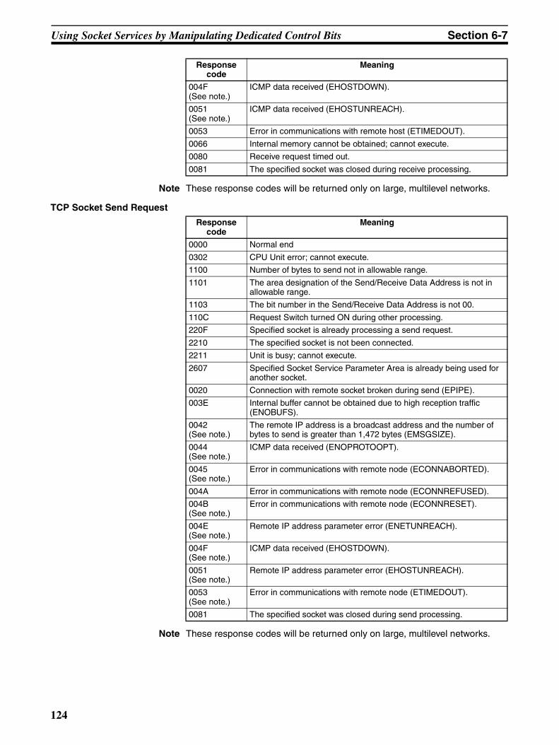
Using Socket Services by Manipulating Dedicated Control Bits Section 6-7
Note These response codes will be returned only on large, multilevel networks.
TCP Socket Send Request
Note These response codes will be returned only on large, multilevel networks.
004F (See note.)
ICMP data received (EHOSTDOWN).
0051 (See note.)
ICMP data received (EHOSTUNREACH).
0053 Error in communications with remote host (ETIMEDOUT).
0066 Internal memory cannot be obtained; cannot execute.
0080 Receive request timed out.
0081 The specified socket was closed during receive processing.
Response code
Meaning
0000 Normal end
0302 CPU Unit error; cannot execute.
1100 Number of bytes to send not in allowable range.
1101 The area designation of the Send/Receive Data Address is not in allowable range.
1103 The bit number in the Send/Receive Data Address is not 00.
110C Request Switch turned ON during other processing.
220F Specified socket is already processing a send request.
2210 The specified socket is not been connected.
2211 Unit is busy; cannot execute.
2607 Specified Socket Service Parameter Area is already being used for another socket.
0020 Connection with remote socket broken during send (EPIPE).
003E Internal buffer cannot be obtained due to high reception traffic (ENOBUFS).
0042 (See note.)
The remote IP address is a broadcast address and the number of bytes to send is greater than 1,472 bytes (EMSGSIZE).
0044 (See note.)
ICMP data received (ENOPROTOOPT).
0045 (See note.)
Error in communications with remote node (ECONNABORTED).
004A Error in communications with remote node (ECONNREFUSED).
004B (See note.)
Error in communications with remote node (ECONNRESET).
004E(See note.)
Remote IP address parameter error (ENETUNREACH).
004F (See note.)
ICMP data received (EHOSTDOWN).
0051 (See note.)
Remote IP address parameter error (EHOSTUNREACH).
0053 (See note.)
Error in communications with remote node (ETIMEDOUT).
0081 The specified socket was closed during send processing.
Response code
Meaning
124
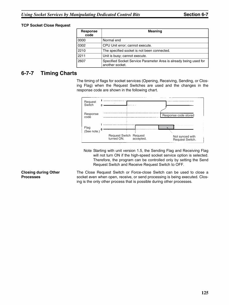
Using Socket Services by Manipulating Dedicated Control Bits Section 6-7
TCP Socket Close Request
6-7-7 Timing ChartsThe timing of flags for socket services (Opening, Receiving, Sending, or Clos-ing Flag) when the Request Switches are used and the changes in theresponse code are shown in the following chart.
Note Starting with unit version 1.5, the Sending Flag and Receiving Flagwill not turn ON if the high-speed socket service option is selected.Therefore, the program can be controlled only by setting the SendRequest Switch and Receive Request Switch to OFF.
Closing during Other Processes
The Close Request Switch or Force-close Switch can be used to close asocket even when open, receive, or send processing is being executed. Clos-ing is the only other process that is possible during other processes.
Response code
Meaning
0000 Normal end
0302 CPU Unit error; cannot execute.
2210 The specified socket is not been connected.
2211 Unit is busy; cannot execute.
2607 Specified Socket Service Parameter Area is already being used for another socket.
Request Switch
Response code
Flag (See note.)
Response code stored
Request Switch turned ON.
Request accepted.
Not synced with Request Switch.
125
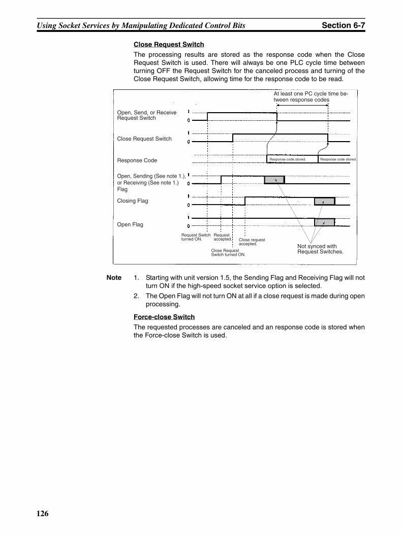
Using Socket Services by Manipulating Dedicated Control Bits Section 6-7
Close Request Switch
The processing results are stored as the response code when the CloseRequest Switch is used. There will always be one PLC cycle time betweenturning OFF the Request Switch for the canceled process and turning of theClose Request Switch, allowing time for the response code to be read.
Note 1. Starting with unit version 1.5, the Sending Flag and Receiving Flag will notturn ON if the high-speed socket service option is selected.
2. The Open Flag will not turn ON at all if a close request is made during openprocessing.
Force-close Switch
The requested processes are canceled and an response code is stored whenthe Force-close Switch is used.
Open, Send, or Receive Request Switch
Close Request Switch
Response Code
Closing Flag
Open Flag
Response code stored. Response code stored.
Request Switch turned ON.
Request accepted.
Close Request Switch turned ON.
Close request accepted. Not synced with
Request Switches.
At least one PC cycle time be-tween response codes
Open, Sending (See note 1.), or Receiving (See note 1.) Flag
126
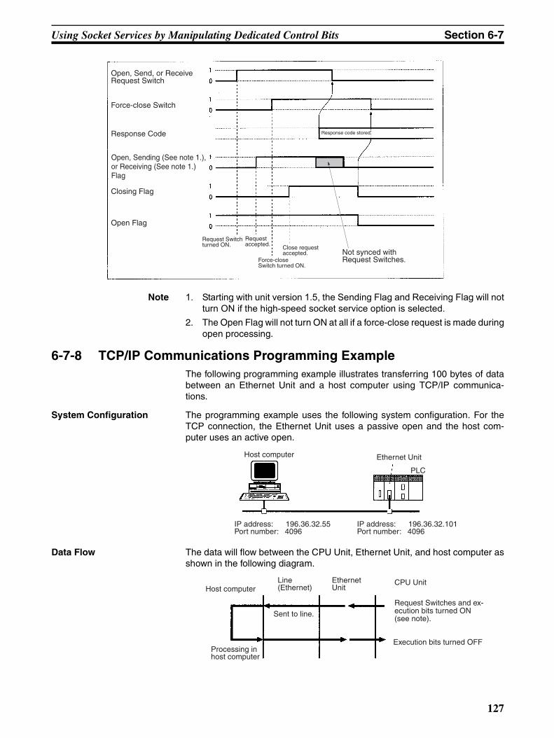
Using Socket Services by Manipulating Dedicated Control Bits Section 6-7
Note 1. Starting with unit version 1.5, the Sending Flag and Receiving Flag will notturn ON if the high-speed socket service option is selected.
2. The Open Flag will not turn ON at all if a force-close request is made duringopen processing.
6-7-8 TCP/IP Communications Programming ExampleThe following programming example illustrates transferring 100 bytes of databetween an Ethernet Unit and a host computer using TCP/IP communica-tions.
System Configuration The programming example uses the following system configuration. For theTCP connection, the Ethernet Unit uses a passive open and the host com-puter uses an active open.
Data Flow The data will flow between the CPU Unit, Ethernet Unit, and host computer asshown in the following diagram.
Open, Send, or Receive Request Switch
Force-close Switch
Response Code
Closing Flag
Open Flag
Response code stored.
Request Switch turned ON.
Request accepted.
Force-close Switch turned ON.
Close request accepted. Not synced with
Request Switches.
Open, Sending (See note 1.), or Receiving (See note 1.) Flag
Host computer Ethernet Unit
IP address: 196.36.32.55Port number: 4096
IP address: 196.36.32.101Port number: 4096
PLC
Host computerLine (Ethernet)
Ethernet Unit
CPU Unit
Request Switches and ex-ecution bits turned ON (see note).
Sent to line.
Processing in host computer
Execution bits turned OFF
127
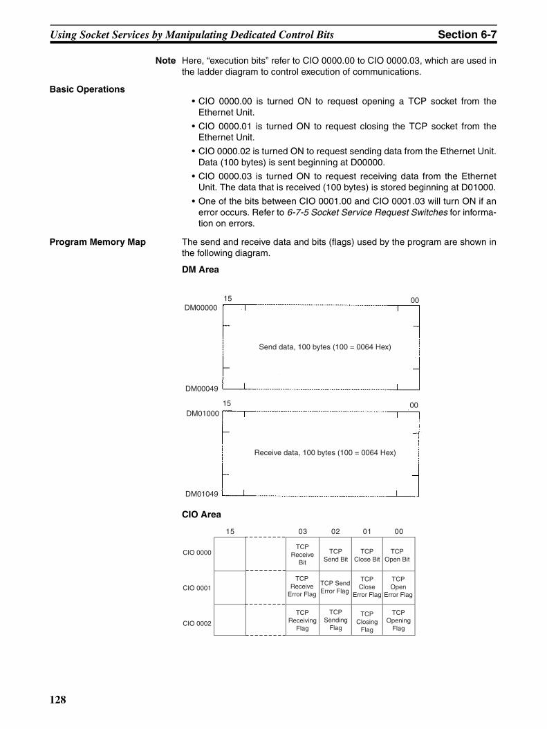
Using Socket Services by Manipulating Dedicated Control Bits Section 6-7
Note Here, “execution bits” refer to CIO 0000.00 to CIO 0000.03, which are used inthe ladder diagram to control execution of communications.
Basic Operations• CIO 0000.00 is turned ON to request opening a TCP socket from the
Ethernet Unit.
• CIO 0000.01 is turned ON to request closing the TCP socket from theEthernet Unit.
• CIO 0000.02 is turned ON to request sending data from the Ethernet Unit.Data (100 bytes) is sent beginning at D00000.
• CIO 0000.03 is turned ON to request receiving data from the EthernetUnit. The data that is received (100 bytes) is stored beginning at D01000.
• One of the bits between CIO 0001.00 and CIO 0001.03 will turn ON if anerror occurs. Refer to 6-7-5 Socket Service Request Switches for informa-tion on errors.
Program Memory Map The send and receive data and bits (flags) used by the program are shown inthe following diagram.
DM Area
CIO Area
Send data, 100 bytes (100 = 0064 Hex)
Receive data, 100 bytes (100 = 0064 Hex)
DM00000
DM00049
DM01000
DM01049
15 00
15 00
CIO 0000
CIO 0001
CIO 0002
15 03 02 01 00
TCP Open Bit
TCP Close Bit
TCP Send Bit
TCP Receive
Bit
TCP Receive
Error Flag
TCP Send Error Flag
TCP Close
Error Flag
TCP Open
Error Flag
TCP Receiving
Flag
TCP Sending
Flag
TCP Closing
Flag
TCP Opening
Flag
128
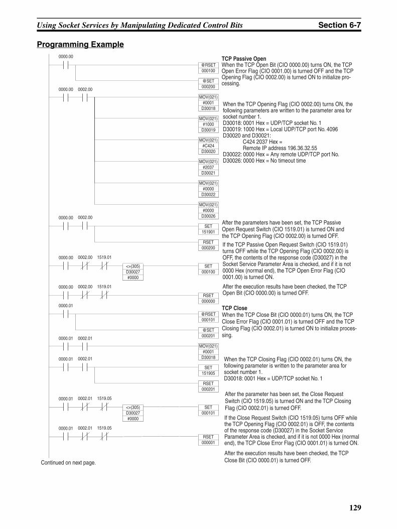
Using Socket Services by Manipulating Dedicated Control Bits Section 6-7
Programming Example
When the TCP Closing Flag (CIO 0002.01) turns ON, the following parameter is written to the parameter area for socket number 1.D30018: 0001 Hex = UDP/TCP socket No. 1
TCP CloseWhen the TCP Close Bit (CIO 0000.01) turns ON, the TCP Close Error Flag (CIO 0001.01) is turned OFF and the TCP Closing Flag (CIO 0002.01) is turned ON to initialize proces-sing.
If the TCP Passive Open Request Switch (CIO 1519.01) turns OFF while the TCP Opening Flag (CIO 0002.00) is OFF, the contents of the response code (D30027) in the Socket Service Parameter Area is checked, and if it is not 0000 Hex (normal end), the TCP Open Error Flag (CIO 0001.00) is turned ON.
After the execution results have been checked, the TCP Open Bit (CIO 0000.00) is turned OFF.
After the parameters have been set, the TCP Passive Open Request Switch (CIO 1519.01) is turned ON and the TCP Opening Flag (CIO 0002.00) is turned OFF.
When the TCP Opening Flag (CIO 0002.00) turns ON, the following parameters are written to the parameter area for socket number 1.D30018: 0001 Hex = UDP/TCP socket No. 1D30019: 1000 Hex = Local UDP/TCP port No. 4096D30020 and D30021:
C424 2037 Hex = Remote IP address 196.36.32.55
D30022: 0000 Hex = Any remote UDP/TCP port No.D30026: 0000 Hex = No timeout time
TCP Passive OpenWhen the TCP Open Bit (CIO 0000.00) turns ON, the TCP Open Error Flag (CIO 0001.00) is turned OFF and the TCP Opening Flag (CIO 0002.00) is turned ON to initialize pro-cessing.
Continued on next page.
After the parameter has been set, the Close Request Switch (CIO 1519.05) is turned ON and the TCP Closing Flag (CIO 0002.01) is turned OFF.
If the Close Request Switch (CIO 1519.05) turns OFF while the TCP Opening Flag (CIO 0002.01) is OFF, the contents of the response code (D30027) in the Socket Service Parameter Area is checked, and if it is not 0000 Hex (normal end), the TCP Close Error Flag (CIO 0001.01) is turned ON.
MOV(021)#0001
D30018
0000.00
0000.00
@RSET000100
@SET000200
MOV(021)#1000
D30019
0002.00
0000.01
SET151905
RSET000201
0002.01
0000.01
SET000101
0002.01 1519.05
<>(305)D30027#0000
0000.00
RSET000000
0002.00 1519.01
0000.01
@RSET000101
@SET000201
MOV(021)#0001
D30018
0000.01 0002.01
0000.00
SET000100
0002.00 1519.01
<>(305)D30027#0000
0000.00
SET151901
RSET000200
0002.00
0000.01
RSET000001
0002.01 1519.05
MOV(021)#C424D30020
MOV(021)#2037
D30021
MOV(021)#0000
D30022
MOV(021)#0000
D30026
After the execution results have been checked, the TCP Close Bit (CIO 0000.01) is turned OFF.
129
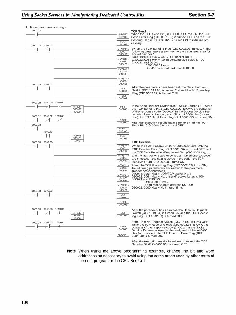
Using Socket Services by Manipulating Dedicated Control Bits Section 6-7
Note When using the above programming example, change the bit and wordaddresses as necessary to avoid using the same areas used by other parts ofthe user program or the CPU Bus Unit.
TCP Receive
If the Send Request Switch (CIO 1519.03) turns OFF while the TCP Sending Flag (CIO 0002.02) is OFF, the contents of the response code (D30027) in the Socket Service Pa-rameter Area is checked, and if it is not 0000 Hex (normal end), the TCP Send Error Flag (CIO 0001.02) is turned ON.
After the execution results have been checked, the TCP Send Bit (CIO 0000.02) is turned OFF.
After the parameters have been set, the Send Request Switch (CIO 1519.03) is turned ON and the TCP Sending Flag (CIO 0002.02) is turned OFF.
When the TCP Sending Flag (CIO 0002.02) turns ON, the following parameters are written to the parameter area for socket number 1.D30018: 0001 Hex = UDP/TCP socket No. 1D30023: 0064 Hex = No. of send/receive bytes is 100D30024 and D30025:
8200 0000 Hex = Send/receive data address D00000
TCP SendWhen the TCP Send Bit (CIO 0000.02) turns ON, the TCP Send Error Flag (CIO 0001.02) is turned OFF and the TCP Sending Flag (CIO 0002.02) is turned ON to initialize pro-cessing.
Continued from previous page.
When the TCP Receive Bit (CIO 0000.03) turns ON, the TCP Receive Error Flag (CIO 0001.03) is turned OFF and the TCP Data Received/Requested Flag (CIO 1509.13), and the Number of Bytes Received at TCP Socket (D30001) are checked. If the data is stored in the buffer, the TCP Receiving Flag (CIO 0002.03) turns ON.
MOV(021)#0001
D30018
0000.02
MOV(021)#0064
D30023
0002.02
0000.03
SET151904
RSET000203
0002.03
0000.03
SET000103
0002.03 1519.04
<>(305)D30027#0000
0000.02
RSET000002
0002.02 1519.03
0000.03
@RSET000103
@SET000203
0000.02
@SET000203
0002.02 1519.03
<>(305)D30027#0000
0000.02
SET151903
RSET000202
0002.02
0000.03
RSET000003
0002.03 1519.04
END(001)
MOV(021)#8200
D30024
MOV(021)#0000
D30025
MOV(021)#0001
D30018
0000.03
MOV(021)#0064
D30023
0002.03
MOV(021)#8203
D30024
MOV(021)#E800
D30025
MOV(021)#0000
D30026
0000.02
@RSET000102
@SET000202
1509.13
=(300)D30001
&100
If the Receive Request Switch (CIO 1519.04) turns OFF while the TCP Receiving Flag (CIO 0002.03) is OFF, the contents of the response code (D30027) in the Socket Service Parameter Area is checked, and if it is not 0000 Hex (normal end), the TCP Receive Error Flag (CIO 0001.03) is turned ON.
After the execution results have been checked, the TCP Receive Bit (CIO 0000.03) is turned OFF.
After the parameter has been set, the Receive Request Switch (CIO 1519.04) is turned ON and the TCP Receiv-ing Flag (CIO 0002.03) is turned OFF.
When the TCP Receiving Flag (CIO 0002.03) turns ON, the following parameters are written to the parameter area for socket number 1.D30018: 0001 Hex = UDP/TCP socket No. 1D30023: 0064 Hex = No. of send/receive bytes is 100D30024 and D30025:
8203 E800 Hex = Send/receive data address D01000
D30026: 0000 Hex = No timeout time.
130
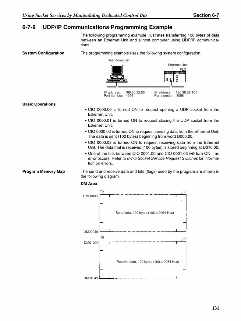
Using Socket Services by Manipulating Dedicated Control Bits Section 6-7
6-7-9 UDP/IP Communications Programming ExampleThe following programming example illustrates transferring 100 bytes of databetween an Ethernet Unit and a host computer using UDP/IP communica-tions.
System Configuration The programming example uses the following system configuration.
Basic Operations• CIO 0000.00 is turned ON to request opening a UDP socket from the
Ethernet Unit.
• CIO 0000.01 is turned ON to request closing the UDP socket from theEthernet Unit.
• CIO 0000.02 is turned ON to request sending data from the Ethernet Unit.The data is sent (100 bytes) beginning from word D000.00.
• CIO 0000.03 is turned ON to request receiving data from the EthernetUnit. The data that is received (100 bytes) is stored beginning at D010.00.
• One of the bits between CIO 0001.00 and CIO 0001.03 will turn ON if anerror occurs. Refer to 6-7-5 Socket Service Request Switches for informa-tion on errors.
Program Memory Map The send and receive data and bits (flags) used by the program are shown inthe following diagram.
DM Area
Host computerEthernet Unit
IP address: 196.36.32.55Port number: 4096
IP address: 196.36.32.101Port number: 4096
PLC
Send data, 100 bytes (100 = 0064 Hex)
Receive data, 100 bytes (100 = 0064 Hex)
DM00000
DM00049
DM01000
DM01049
15 00
15 00
131

Using Socket Services by Manipulating Dedicated Control Bits Section 6-7
CIO Area
CIO 0000
CIO 0001
CIO 0002
15 03 02 01 00
UDP Open Bit
UDP Close Bit
UDP Send Bit
UDP Receive
Bit
UDP Receive
Error Flag
UDP Send Error Flag
UDP Close
Error Flag
UDP Open
Error Flag
UDP Receiving
Flag
UDP Sending
Flag
UDP Closing
Flag
UDP Opening
Flag
132
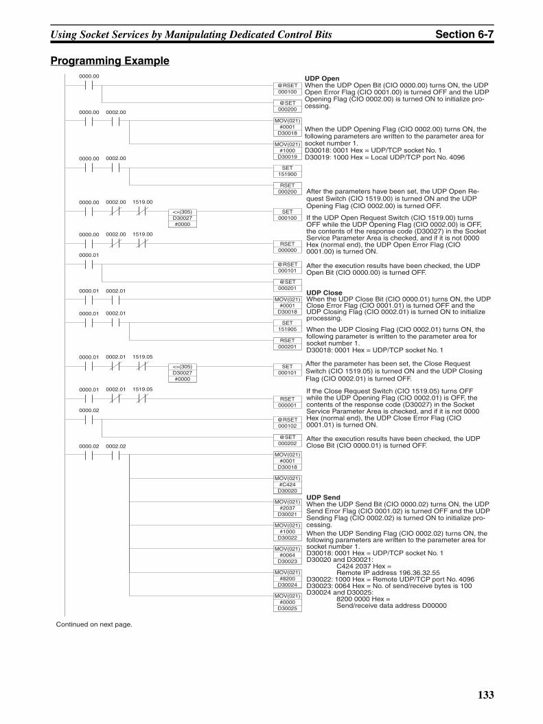
Using Socket Services by Manipulating Dedicated Control Bits Section 6-7
Programming Example
If the Close Request Switch (CIO 1519.05) turns OFF while the UDP Opening Flag (CIO 0002.01) is OFF, the contents of the response code (D30027) in the Socket Service Parameter Area is checked, and if it is not 0000 Hex (normal end), the UDP Close Error Flag (CIO 0001.01) is turned ON.
After the execution results have been checked, the UDP Close Bit (CIO 0000.01) is turned OFF.
After the parameter has been set, the Close Request Switch (CIO 1519.05) is turned ON and the UDP Closing Flag (CIO 0002.01) is turned OFF.
When the UDP Closing Flag (CIO 0002.01) turns ON, the following parameter is written to the parameter area for socket number 1.D30018: 0001 Hex = UDP/TCP socket No. 1
UDP CloseWhen the UDP Close Bit (CIO 0000.01) turns ON, the UDP Close Error Flag (CIO 0001.01) is turned OFF and the UDP Closing Flag (CIO 0002.01) is turned ON to initialize processing.
If the UDP Open Request Switch (CIO 1519.00) turns OFF while the UDP Opening Flag (CIO 0002.00) is OFF, the contents of the response code (D30027) in the Socket Service Parameter Area is checked, and if it is not 0000 Hex (normal end), the UDP Open Error Flag (CIO 0001.00) is turned ON.
After the execution results have been checked, the UDP Open Bit (CIO 0000.00) is turned OFF.
After the parameters have been set, the UDP Open Re-quest Switch (CIO 1519.00) is turned ON and the UDP Opening Flag (CIO 0002.00) is turned OFF.
When the UDP Opening Flag (CIO 0002.00) turns ON, the following parameters are written to the parameter area for socket number 1.D30018: 0001 Hex = UDP/TCP socket No. 1D30019: 1000 Hex = Local UDP/TCP port No. 4096
UDP OpenWhen the UDP Open Bit (CIO 0000.00) turns ON, the UDP Open Error Flag (CIO 0001.00) is turned OFF and the UDP Opening Flag (CIO 0002.00) is turned ON to initialize pro-cessing.
UDP SendWhen the UDP Send Bit (CIO 0000.02) turns ON, the UDP Send Error Flag (CIO 0001.02) is turned OFF and the UDP Sending Flag (CIO 0002.02) is turned ON to initialize pro-cessing.
Continued on next page.
MOV(021)#0001
D30018
0000.00
0000.00
@RSET000100
@SET000200
MOV(021)#1000
D30019
0002.00
0000.01
SET151905
RSET000201
0002.01
0000.01
SET000101
0002.01 1519.05
<>(305)D30027#0000
0000.00
RSET000000
0002.00 1519.00
0000.01
@RSET000101
@SET000201
MOV(021)#0001
D30018
0000.01 0002.01
0000.00
SET000100
0002.00 1519.00
<>(305)D30027#0000
0000.00
SET151900
RSET000200
0002.00
0000.01
RSET000001
0002.01 1519.05
0000.02
@RSET000102
@SET000202
MOV(021)#0001
D30018
0000.02
MOV(021)#C424
D30020
0002.02
MOV(021)#2037
D30021
MOV(021)#1000
D30022
MOV(021)#0064
D30023
MOV(021)#8200
D30024
MOV(021)#0000
D30025
When the UDP Sending Flag (CIO 0002.02) turns ON, the following parameters are written to the parameter area for socket number 1.D30018: 0001 Hex = UDP/TCP socket No. 1D30020 and D30021:
C424 2037 Hex = Remote IP address 196.36.32.55
D30022: 1000 Hex = Remote UDP/TCP port No. 4096D30023: 0064 Hex = No. of send/receive bytes is 100D30024 and D30025:
8200 0000 Hex = Send/receive data address D00000
133
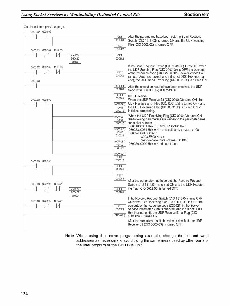
Using Socket Services by Manipulating Dedicated Control Bits Section 6-7
Note When using the above programming example, change the bit and wordaddresses as necessary to avoid using the same areas used by other parts ofthe user program or the CPU Bus Unit.
UDP ReceiveWhen the UDP Receive Bit (CIO 0000.03) turns ON, the UDP Receive Error Flag (CIO 0001.03) is turned OFF and the UDP Receiving Flag (CIO 0002.03) is turned ON to initialize processing.
If the Send Request Switch (CIO 1519.03) turns OFF while the UDP Sending Flag (CIO 0002.00) is OFF, the contents of the response code (D30027) in the Socket Service Pa-rameter Area is checked, and if it is not 0000 Hex (normal end), the UDP Send Error Flag (CIO 0001.02) is turned ON.
After the execution results have been checked, the UDP Send Bit (CIO 0000.02) is turned OFF.
After the parameters have been set, the Send Request Switch (CIO 1519.03) is turned ON and the UDP Sending Flag (CIO 0002.02) is turned OFF.
Continued from previous page.
0000.03
RSET000003
0002.03 1519.04
0000.02
SET151903
RSET000202
0002.02
0000.02
SET000102
0002.02 1519.03
<>(305)D30027#0000
0000.02
RSET000002
0002.02 1519.03
0000.03
@RSET000103
@SET000203
MOV(021)#0001
D30018
0000.03
MOV(021)#0064
D30023
0002.03
MOV(021)#8203
D30024
MOV(021)#E800
D30025
MOV(021)#0000
D300260000.03
SET151904
RSET000203
0002.03
0000.03
SET000103
0002.03 1519.04
<>(305)D30027#0000
END(001)
If the Receive Request Switch (CIO 1519.04) turns OFF while the UDP Receiving Flag (CIO 0002.03) is OFF, the contents of the response code (D30027) in the Socket Service Parameter Area is checked, and if it is not 0000 Hex (normal end), the UDP Receive Error Flag (CIO 0001.03) is turned ON. After the execution results have been checked, the UDP Receive Bit (CIO 0000.03) is turned OFF.
After the parameter has been set, the Receive Request Switch (CIO 1519.04) is turned ON and the UDP Receiv-ing Flag (CIO 0002.03) is turned OFF.
When the UDP Receiving Flag (CIO 0002.03) turns ON, the following parameters are written to the parameter area for socket number 1.D30018: 0001 Hex = UDP/TCP socket No. 1D30023: 0064 Hex = No. of send/receive bytes is 100D30024 and D30025:
8203 E800 Hex = Send/receive data address D01000
D30026: 0000 Hex = No timeout time.
134
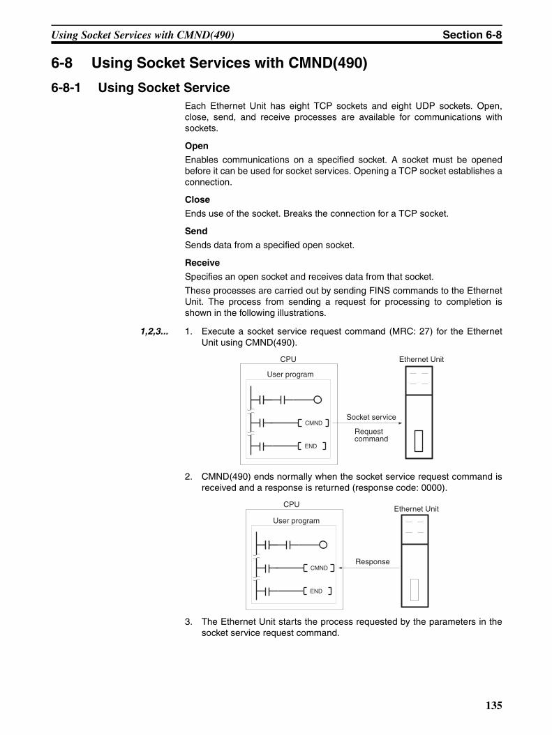
Using Socket Services with CMND(490) Section 6-8
6-8 Using Socket Services with CMND(490)
6-8-1 Using Socket ServiceEach Ethernet Unit has eight TCP sockets and eight UDP sockets. Open,close, send, and receive processes are available for communications withsockets.
Open
Enables communications on a specified socket. A socket must be openedbefore it can be used for socket services. Opening a TCP socket establishes aconnection.
Close
Ends use of the socket. Breaks the connection for a TCP socket.
Send
Sends data from a specified open socket.
Receive
Specifies an open socket and receives data from that socket.
These processes are carried out by sending FINS commands to the EthernetUnit. The process from sending a request for processing to completion isshown in the following illustrations.
1,2,3... 1. Execute a socket service request command (MRC: 27) for the EthernetUnit using CMND(490).
2. CMND(490) ends normally when the socket service request command isreceived and a response is returned (response code: 0000).
3. The Ethernet Unit starts the process requested by the parameters in thesocket service request command.
Socket service
Request command
CPU
User program
Ethernet Unit
CMND
END
Ethernet Unit
Response
CPU
User program
CMND
END
135
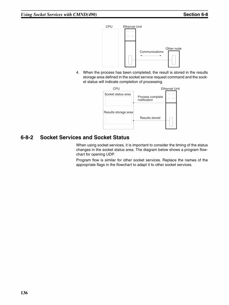
Using Socket Services with CMND(490) Section 6-8
4. When the process has been completed, the result is stored in the resultsstorage area defined in the socket service request command and the sock-et status will indicate completion of processing.
6-8-2 Socket Services and Socket StatusWhen using socket services, it is important to consider the timing of the statuschanges in the socket status area. The diagram below shows a program flow-chart for opening UDP.
Program flow is similar for other socket services. Replace the names of theappropriate flags in the flowchart to adapt it to other socket services.
CPU Ethernet Unit
CommunicationsOther node
CPU
Socket status area
Results storage area
Ethernet Unit
Process complete notification
Results stored
136
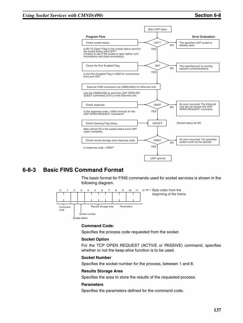
Using Socket Services with CMND(490) Section 6-8
6-8-3 Basic FINS Command FormatThe basic format for FINS commands used for socket services is shown in thefollowing diagram.
Command Code:
Specifies the process code requested from the socket.
Socket Option
For the TCP OPEN REQUEST (ACTIVE or PASSIVE) command, specifieswhether or not the keep-alive function is to be used.
Socket Number
Specifies the socket number for the process, between 1 and 8.
Results Storage Area
Specifies the area to store the results of the requested process.
Parameters
Specifies the parameters defined for the command code.
An error occurred. The Ethernet Unit did not receive the UDP OPEN REQUEST command.
Check socket status.
Start UDP Open
OFF?
ON/OFF
The specified UDP socket is already open.
Program Flow
Is Bit 15 (Open Flag) in the socket status word for the socket being used OFF? (Checks to see if the socket is open before com-munications and close processing.)
YES
Error Evaluation
Check the Port Enabled Flag.
Check response.
Check Opening Flag status.
Check results storage area response code.
ON? The specified port is running network communications.
Is the Port Enabled Flag in A502 for communica-tions port ON?
YES
Use the CMND(490) to send the UDP OPEN RE-QUEST command (2701) to the Ethernet Unit.
Is the response code = 0000 (normal) for the UDP OPEN REQUEST command?
Wait until bit 00 in the socket status turns OFF (open complete).
Is response code = 0000?
0000?
YES
0000?
YES
UDP opened
(Socket status bit 00)
An error occurred. The specified socket could not be opened.
NO
NO
NO
NO
Execute FINS command (via CMND(490)) for Ethernet Unit.
0 1 2 3 4 5 6 7 8 9 10 11 12
Command code
Socket option
Socket number
Results storage area Parameters
Byte order from the beginning of the frame
137
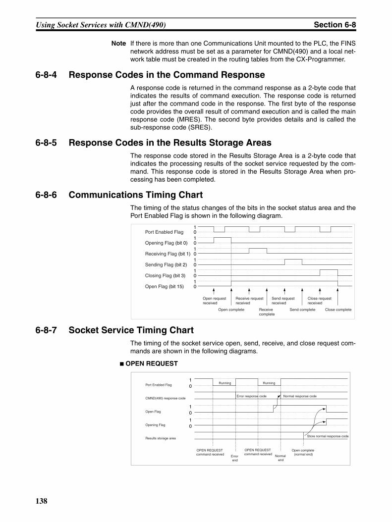
Using Socket Services with CMND(490) Section 6-8
Note If there is more than one Communications Unit mounted to the PLC, the FINSnetwork address must be set as a parameter for CMND(490) and a local net-work table must be created in the routing tables from the CX-Programmer.
6-8-4 Response Codes in the Command ResponseA response code is returned in the command response as a 2-byte code thatindicates the results of command execution. The response code is returnedjust after the command code in the response. The first byte of the responsecode provides the overall result of command execution and is called the mainresponse code (MRES). The second byte provides details and is called thesub-response code (SRES).
6-8-5 Response Codes in the Results Storage AreasThe response code stored in the Results Storage Area is a 2-byte code thatindicates the processing results of the socket service requested by the com-mand. This response code is stored in the Results Storage Area when pro-cessing has been completed.
6-8-6 Communications Timing ChartThe timing of the status changes of the bits in the socket status area and thePort Enabled Flag is shown in the following diagram.
6-8-7 Socket Service Timing ChartThe timing of the socket service open, send, receive, and close request com-mands are shown in the following diagrams.
OPEN REQUEST
Open request received
Open complete
Receive request received
Receive complete
Send request received
Send complete
Close request received
Close complete
10
10
10
10
10
10Port Enabled Flag
Opening Flag (bit 0)
Receiving Flag (bit 1)
Sending Flag (bit 2)
Closing Flag (bit 3)
Open Flag (bit 15)
OPEN REQUEST command received Error
end
OPEN REQUEST command received Normal
end
Open complete (normal end)
Store normal response code
10
10
10
Normal response codeError response code
RunningRunning
CMND(490) response code
Results storage area
Port Enabled Flag
Open Flag
Opening Flag
138
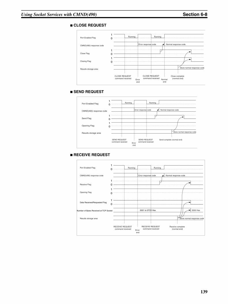
Using Socket Services with CMND(490) Section 6-8
CLOSE REQUEST
SEND REQUEST
RECEIVE REQUEST
CLOSE REQUEST command received Error
end
CLOSE REQUEST command received Normal
end
Close complete (normal end)
10
10
10
Normal response code
RunningRunning
CMND(490) response code
Close Flag
Closing Flag
Results storage area
Port Enabled Flag
Error response code
Store normal response code
SEND REQUEST command received
Error end
SEND REQUEST command received
Send complete (normal end)
10
10
10
Normal response code
RunningRunning
Send Flag
Results storage area Store normal response code
Error response codeCMND(490) response code
Port Enabled Flag
Opening Flag
RECEIVE REQUEST command received Error
end
RECEIVE REQUEST command received
Receive complete (normal end)
10
10
10
Normal response code
RunningRunning
Receive Flag
Results storage area Store normal response code
Error response codeCMND(490) response code
Port Enabled Flag
Opening Flag
10
Number of Bytes Received at TCP Socket
Data Received/Requested Flag
0001 to 07CD Hex 0000 Hex
139
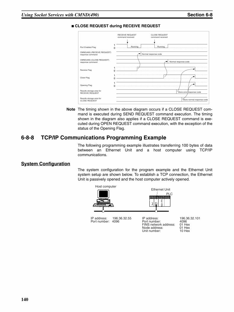
Using Socket Services with CMND(490) Section 6-8
CLOSE REQUEST during RECEIVE REQUEST
Note The timing shown in the above diagram occurs if a CLOSE REQUEST com-mand is executed during SEND REQUEST command execution. The timingshown in the diagram also applies if a CLOSE REQUEST command is exe-cuted during OPEN REQUEST command execution, with the exception of thestatus of the Opening Flag.
6-8-8 TCP/IP Communications Programming ExampleThe following programming example illustrates transferring 100 bytes of databetween an Ethernet Unit and a host computer using TCP/IPcommunications.
System ConfigurationThe system configuration for the program example and the Ethernet Unitsystem setup are shown below. To establish a TCP connection, the EthernetUnit is passively opened and the host computer actively opened.
RECEIVE REQUEST command received
CLOSE REQUEST command received
10
10
Normal response code
RunningRunning
CMND(490) (CLOSE REQUEST) response command
Results storage area for RECEIVE REQUEST
Results storage area for CLOSE REQUEST
Normal response codeCMND(490) (RECEIVE REQUEST) response command
10Close Flag
10Receive Flag
Store error response code
Opening Flag
Store normal response code
Port Enabled Flag
Host computerEthernet Unit
IP address: 196.36.32.55Port number: 4096
IP address: 196.36.32.101Port number: 4096FINS network address: 01 HexNode address: 01 HexUnit number: 10 Hex
PLC
140
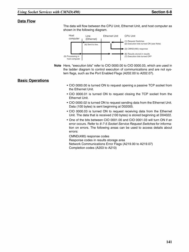
Using Socket Services with CMND(490) Section 6-8
Data FlowThe data will flow between the CPU Unit, Ethernet Unit, and host computer asshown in the following diagram.
Note Here, “execution bits” refer to CIO 0000.00 to CIO 0000.03, which are used inthe ladder diagram to control execution of communications and are not sys-tem flags, such as the Port Enabled Flags (A202.00 to A202.07).
Basic Operations• CIO 0000.00 is turned ON to request opening a passive TCP socket from
the Ethernet Unit.
• CIO 0000.01 is turned ON to request closing the TCP socket from theEthernet Unit.
• CIO 0000.02 is turned ON to request sending data from the Ethernet Unit.Data (100 bytes) is sent beginning at D02005.
• CIO 0000.03 is turned ON to request receiving data from the EthernetUnit. The data that is received (100 bytes) is stored beginning at D04022.
• One of the bits between CIO 0001.00 and CIO 0001.03 will turn ON if anerror occurs. Refer to 6-7-5 Socket Service Request Switches for informa-tion on errors. The following areas can be used to access details abouterrors:
CMND(490) response codesResponse codes in results storage areaNetwork Communications Error Flags (A219.00 to A219.07)Completion codes (A203 to A210)
(1) Request Switches(2) Execution bits turned ON (see Note)
(3) CMND(490) response
(6) Results stored in results (7) Execution bits turned OFF
CPU UnitEthernet UnitLine (Ethernet)
Host computer
(4) Sent to line.
(5) Processing in host computer
141
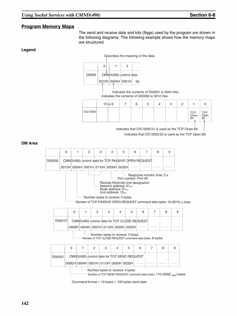
Using Socket Services with CMND(490) Section 6-8
Program Memory MapsThe send and receive data and bits (flags) used by the program are shown inthe following diagrams. The following example shows how the memory mapsare structured.
Legend
DM Area
0012H 0004H 0001H
0 1 2
D0000 CMND(490) control data
00
7 6 5 4 3 2 1 0
CIO 0000
15 to 8
TCP Close Bit
TCP Open Bit
Describes the meaning of the data.
Indicates the contents of D00000 is 0012 Hex. Indicates the contents of D00001 is 0004 Hex.
Indicates that CIO 0000.01 is used as the TCP Close Bit.
Indicates that CIO 0000.00 is used as the TCP Open Bit.
0012H 0004H 0001H 0110H 0000H 0032H
0 1 2 3 4 5 6 7 8 9
D00000
Number of TCP PASSIVE OPEN REQUEST command data bytes: 18 (0012hex) bytes
Number bytes to receive: 4 bytes
Remote Ethernet Unit designationNetwork address: 01hex
Node address: 01hex
Unit address: 10hex
Port number: Port #0Response monitor time: 5 s
CMND(490) control data for TCP PASSIVE OPEN REQUEST
0008H 0004H 0001H 0110H 0000H 0032H
0 1 2 3 4 5 6 7 8 9
D00010 CMND(490) control data for TCP CLOSE REQUEST
Number of TCP CLOSE REQUEST command data bytes: 8 bytesNumber bytes to receive: 4 bytes
Number bytes to receive: 4 bytes
006EH 0004H 0001H 0110H 0000H 0032H
0 1 2 3 4 5 6 7 8 9
D00020 CMND(490) control data for TCP SEND REQUEST
Command format = 10 bytes + 100 bytes send data
Number of TCP SEND REQUEST command data bytes: 110 (006E hex) bytes
142
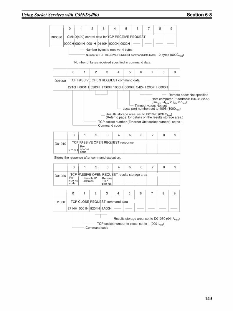
Using Socket Services with CMND(490) Section 6-8
Number bytes to receive: 4 bytes
000CH 0004H 0001H 0110H 0000H 0032H
0 1 2 3 4 5 6 7 8 9
D00030 CMND(490) control data for TCP RECEIVE REQUEST
Number of bytes received specified in command data.
Number of TCP RECEIVE REQUEST command data bytes: 12 bytes (000Chex)
2710H 0001H 8203H FC00H 1000H 0000H
0 1 2 3 4 5 6 7 8 9
D01000
C424H 2037H 0000H
TCP PASSIVE OPEN REQUEST command data
Command codeTCP socket number (Ethernet Unit socket number): set to 1
Results storage area: set to D01020 (03FChex) (Refer to page for details on the results storage area.)
Local port number: set to 4096 (1000hex)Timeout value: Not set
Host computer IP address: 196.36.32.55 (C4hex.24hex.20hex.37hex)
Remote node: Not specified
2710H
0 1 2 3 4 5 6 7 8 9
D01010Re-sponse code
TCP PASSIVE OPEN REQUEST response
Stores the response after command execution.
0 1 2 3 4 5 6 7 8 9
D01020 TCP PASSIVE OPEN REQUEST results storage areaRe-sponse code
Remote IP address
Remote TCP port No.
2714H 0001H 8204H 1A00H
0 1 2 3 4 5 6 7 8 9
D1030 TCP CLOSE REQUEST command data
Command codeTCP socket number to close: set to 1 (0001hex)
Results storage area: set to D01050 (041Ahex)
143
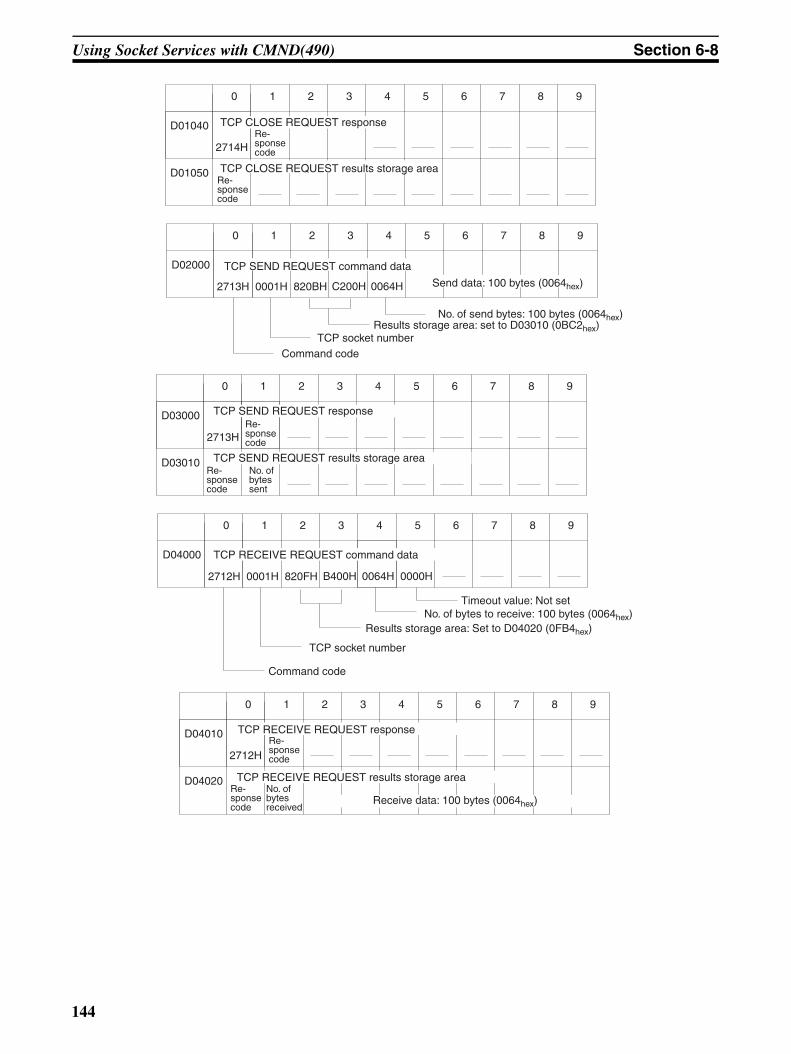
Using Socket Services with CMND(490) Section 6-8
2713H 0001H 820BH C200H
0 1 2 3 4 5 6 7 8 9
D02000
2714H
0 1 2 3 4 5 6 7 8 9
D01040
D01050
0064H
TCP CLOSE REQUEST responseRe-sponse code
TCP CLOSE REQUEST results storage area
TCP SEND REQUEST command data
Send data: 100 bytes (0064hex)
Command codeTCP socket number
Results storage area: set to D03010 (0BC2hex) No. of send bytes: 100 bytes (0064hex)
Re-sponse code
2712H 0001H 820FH B400H
0 1 2 3 4 5 6 7 8 9
D04000
2713H
0 1 2 3 4 5 6 7 8 9
D03000
D03010
0064H 0000H
TCP SEND REQUEST responseRe-sponse code
TCP SEND REQUEST results storage area
TCP RECEIVE REQUEST command data
No. of bytes to receive: 100 bytes (0064hex)Timeout value: Not set
Command code
TCP socket number
Results storage area: Set to D04020 (0FB4hex)
Re-sponse code
No. of bytes sent
2712H
0 1 2 3 4 5 6 7 8 9
D04010
D04020
TCP RECEIVE REQUEST responseRe-sponse code
TCP RECEIVE REQUEST results storage areaNo. of bytes received
Receive data: 100 bytes (0064hex)Re-sponse code
144
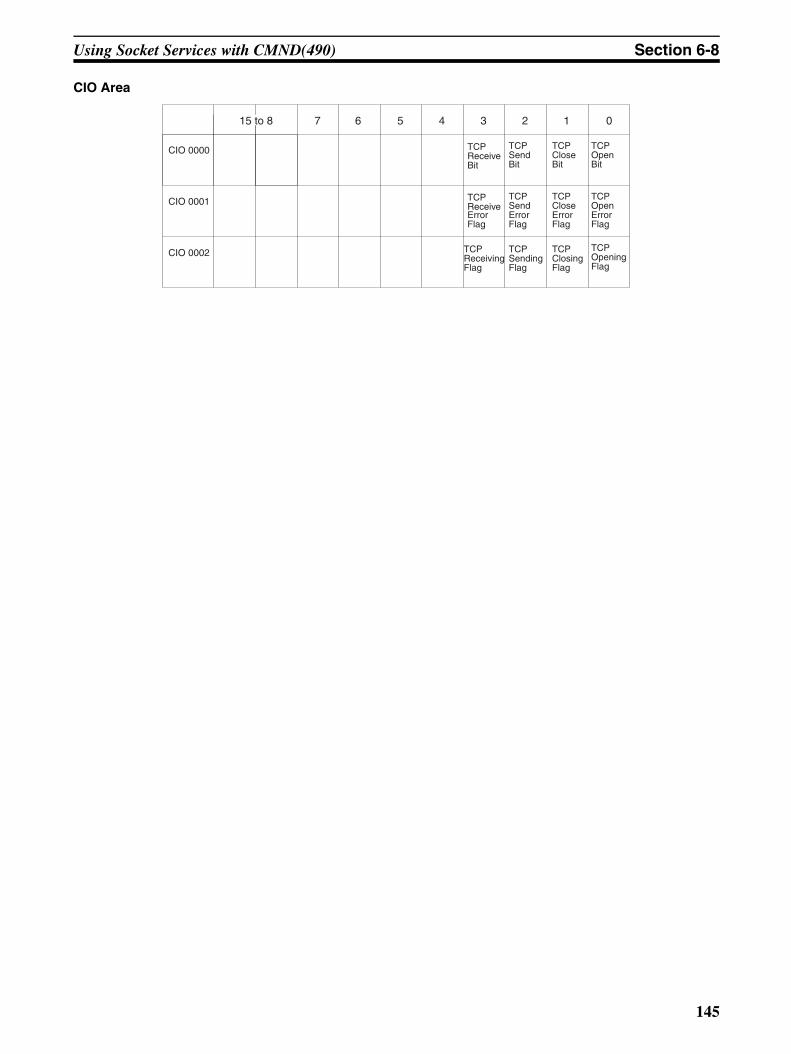
Using Socket Services with CMND(490) Section 6-8
CIO Area
7 6 5 4 3 2 1 0
CIO 0000
CIO 0001
15 to 8
CIO 0002
TCP Send Bit
TCP Close Bit
TCP Open Bit
TCP Receive Error Flag
TCP Send Error Flag
TCP Close Error Flag
TCP Open Error Flag
TCP Receiving Flag
TCP Sending Flag
TCP Closing Flag
TCP Opening Flag
TCP Receive Bit
145
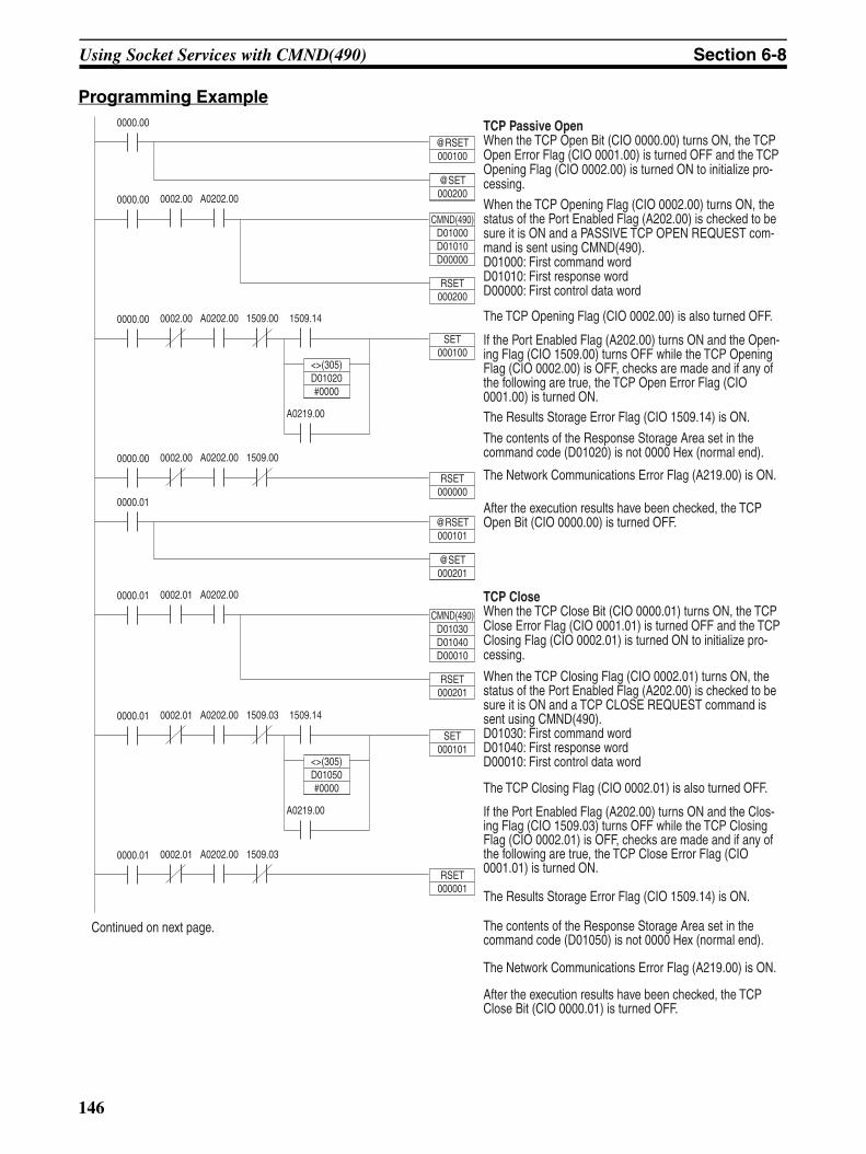
Using Socket Services with CMND(490) Section 6-8
Programming Example
If the Port Enabled Flag (A202.00) turns ON and the Clos-ing Flag (CIO 1509.03) turns OFF while the TCP Closing Flag (CIO 0002.01) is OFF, checks are made and if any of the following are true, the TCP Close Error Flag (CIO 0001.01) is turned ON.
The Results Storage Error Flag (CIO 1509.14) is ON.
The contents of the Response Storage Area set in the command code (D01050) is not 0000 Hex (normal end).
The Network Communications Error Flag (A219.00) is ON.
After the execution results have been checked, the TCP Close Bit (CIO 0000.01) is turned OFF.
When the TCP Closing Flag (CIO 0002.01) turns ON, the status of the Port Enabled Flag (A202.00) is checked to be sure it is ON and a TCP CLOSE REQUEST command is sent using CMND(490).D01030: First command wordD01040: First response wordD00010: First control data word
The TCP Closing Flag (CIO 0002.01) is also turned OFF.
TCP CloseWhen the TCP Close Bit (CIO 0000.01) turns ON, the TCP Close Error Flag (CIO 0001.01) is turned OFF and the TCP Closing Flag (CIO 0002.01) is turned ON to initialize pro-cessing.
If the Port Enabled Flag (A202.00) turns ON and the Open-ing Flag (CIO 1509.00) turns OFF while the TCP Opening Flag (CIO 0002.00) is OFF, checks are made and if any of the following are true, the TCP Open Error Flag (CIO 0001.00) is turned ON. The Results Storage Error Flag (CIO 1509.14) is ON.
The contents of the Response Storage Area set in the command code (D01020) is not 0000 Hex (normal end).
The Network Communications Error Flag (A219.00) is ON.
After the execution results have been checked, the TCP Open Bit (CIO 0000.00) is turned OFF.
When the TCP Opening Flag (CIO 0002.00) turns ON, the status of the Port Enabled Flag (A202.00) is checked to be sure it is ON and a PASSIVE TCP OPEN REQUEST com-mand is sent using CMND(490).D01000: First command wordD01010: First response wordD00000: First control data word
The TCP Opening Flag (CIO 0002.00) is also turned OFF.
TCP Passive OpenWhen the TCP Open Bit (CIO 0000.00) turns ON, the TCP Open Error Flag (CIO 0001.00) is turned OFF and the TCP Opening Flag (CIO 0002.00) is turned ON to initialize pro-cessing.
Continued on next page.
CMND(490)D01000D01010D00000
0000.00
@RSET000100
@SET000200
0000.00
SET000100
0002.00 A0202.00
0000.00 0002.00 A0202.00
RSET000200
<>(305)D01020#0000
1509.00 1509.14
A0219.00
0000.00
RSET000000
0002.00 A0202.00 1509.00
0000.01
@RSET000101
@SET000201
CMND(490)D01030D01040D00010
0000.01 0002.01 A0202.00
RSET000201
0000.01
SET000101
0002.01 A0202.00
<>(305)D01050#0000
1509.03 1509.14
A0219.00
0000.01
RSET000001
0002.01 A0202.00 1509.03
146
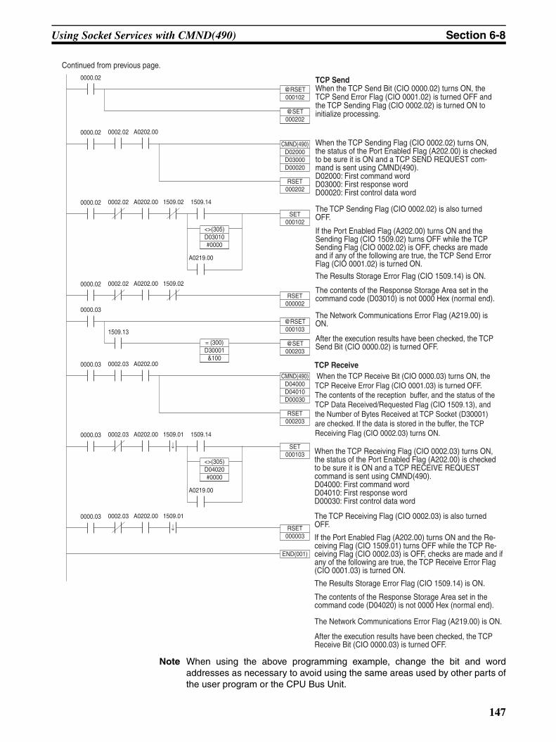
Using Socket Services with CMND(490) Section 6-8
Note When using the above programming example, change the bit and wordaddresses as necessary to avoid using the same areas used by other parts ofthe user program or the CPU Bus Unit.
When the TCP Receiving Flag (CIO 0002.03) turns ON, the status of the Port Enabled Flag (A202.00) is checked to be sure it is ON and a TCP RECEIVE REQUEST command is sent using CMND(490).D04000: First command wordD04010: First response wordD00030: First control data word
The TCP Receiving Flag (CIO 0002.03) is also turned OFF.
TCP Receive
When the TCP Sending Flag (CIO 0002.02) turns ON, the status of the Port Enabled Flag (A202.00) is checked to be sure it is ON and a TCP SEND REQUEST com-mand is sent using CMND(490).D02000: First command wordD03000: First response wordD00020: First control data word
The TCP Sending Flag (CIO 0002.02) is also turned OFF.
TCP SendWhen the TCP Send Bit (CIO 0000.02) turns ON, the TCP Send Error Flag (CIO 0001.02) is turned OFF and the TCP Sending Flag (CIO 0002.02) is turned ON to initialize processing.
Continued from previous page.
If the Port Enabled Flag (A202.00) turns ON and the Sending Flag (CIO 1509.02) turns OFF while the TCP Sending Flag (CIO 0002.02) is OFF, checks are made and if any of the following are true, the TCP Send Error Flag (CIO 0001.02) is turned ON.
The Results Storage Error Flag (CIO 1509.14) is ON.
The contents of the Response Storage Area set in the command code (D03010) is not 0000 Hex (normal end).
The Network Communications Error Flag (A219.00) is ON.
After the execution results have been checked, the TCP Send Bit (CIO 0000.02) is turned OFF.
If the Port Enabled Flag (A202.00) turns ON and the Re-ceiving Flag (CIO 1509.01) turns OFF while the TCP Re-ceiving Flag (CIO 0002.03) is OFF, checks are made and if any of the following are true, the TCP Receive Error Flag (CIO 0001.03) is turned ON.
The Results Storage Error Flag (CIO 1509.14) is ON.
The contents of the Response Storage Area set in the command code (D04020) is not 0000 Hex (normal end).
The Network Communications Error Flag (A219.00) is ON.
After the execution results have been checked, the TCP Receive Bit (CIO 0000.03) is turned OFF.
When the TCP Receive Bit (CIO 0000.03) turns ON, the TCP Receive Error Flag (CIO 0001.03) is turned OFF.The contents of the reception buffer, and the status of the TCP Data Received/Requested Flag (CIO 1509.13), and the Number of Bytes Received at TCP Socket (D30001) are checked. If the data is stored in the buffer, the TCP Receiving Flag (CIO 0002.03) turns ON.
CMND(490)D02000D03000D00020
0000.02
SET000102
0002.02 A0202.00
0000.02 0002.02 A0202.00
RSET000202
<>(305)D03010#0000
1509.02 1509.14
A0219.00
0000.02
RSET000002
0002.02 A0202.00 1509.02
0000.03
@RSET000103
@SET000203
CMND(490)D04000D04010D00030
0000.03 0002.03 A0202.00
1509.13
RSET000203
0000.03
SET000103
0002.03 A0202.00
<>(305)D04020#0000
1509.01 1509.14
A0219.00
= (300)D30001
&100
0000.03
RSET000003
0002.03 A0202.00 1509.01
END(001)
0000.02
@RSET000102
@SET000202
↓
↓
147
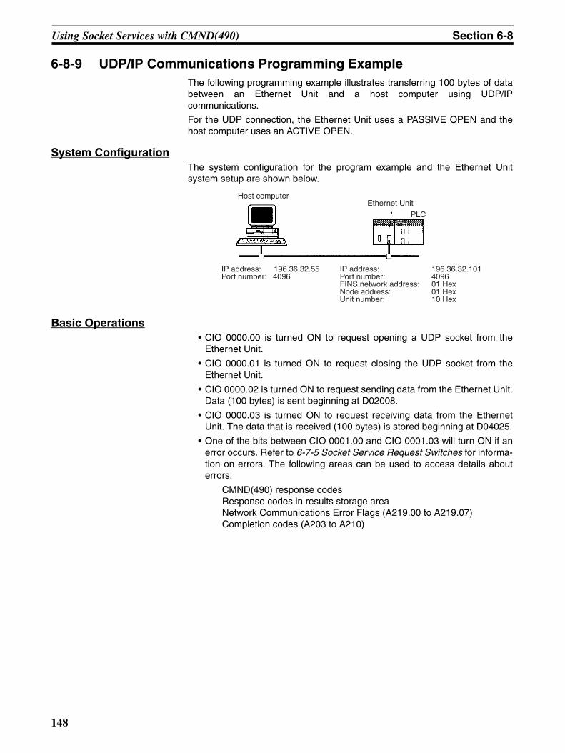
Using Socket Services with CMND(490) Section 6-8
6-8-9 UDP/IP Communications Programming ExampleThe following programming example illustrates transferring 100 bytes of databetween an Ethernet Unit and a host computer using UDP/IPcommunications.
For the UDP connection, the Ethernet Unit uses a PASSIVE OPEN and thehost computer uses an ACTIVE OPEN.
System ConfigurationThe system configuration for the program example and the Ethernet Unitsystem setup are shown below.
Basic Operations• CIO 0000.00 is turned ON to request opening a UDP socket from the
Ethernet Unit.
• CIO 0000.01 is turned ON to request closing the UDP socket from theEthernet Unit.
• CIO 0000.02 is turned ON to request sending data from the Ethernet Unit.Data (100 bytes) is sent beginning at D02008.
• CIO 0000.03 is turned ON to request receiving data from the EthernetUnit. The data that is received (100 bytes) is stored beginning at D04025.
• One of the bits between CIO 0001.00 and CIO 0001.03 will turn ON if anerror occurs. Refer to 6-7-5 Socket Service Request Switches for informa-tion on errors. The following areas can be used to access details abouterrors:
CMND(490) response codesResponse codes in results storage areaNetwork Communications Error Flags (A219.00 to A219.07)Completion codes (A203 to A210)
Host computerEthernet Unit
IP address: 196.36.32.55Port number: 4096
IP address: 196.36.32.101Port number: 4096FINS network address: 01 HexNode address: 01 HexUnit number: 10 Hex
PLC
148
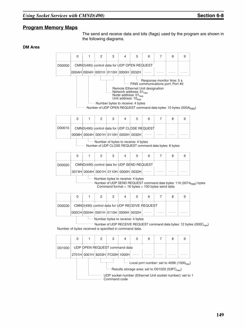
Using Socket Services with CMND(490) Section 6-8
Program Memory MapsThe send and receive data and bits (flags) used by the program are shown inthe following diagrams.
DM Area
000AH 0004H 0001H 0110H 0000H 0032H
0 1 2 3 4 5 6 7 8 9
D00000
Number bytes to receive: 4 bytes
Remote Ethernet Unit designationNetwork address: 01hexNode address: 01hexUnit address: 10hex
FINS communications port: Port #0Response monitor time: 5 s
CMND(490) control data for UDP OPEN REQUEST
Number of UDP OPEN REQUEST command data bytes: 10 bytes (000Ahex)
0008H 0004H 0001H 0110H 0000H 0032H
0 1 2 3 4 5 6 7 8 9
D00010 CMND(490) control data for UDP CLOSE REQUEST
Number of bytes to receive: 4 bytesNumber of UDP CLOSE REQUEST command data bytes: 8 bytes
Number bytes to receive: 4 bytes
0074H 0004H 0001H 0110H 0000H 0032H
0 1 2 3 4 5 6 7 8 9
D00020 CMND(490) control data for UDP SEND REQUEST
Command format = 16 bytes + 100 bytes send dataNumber of UDP SEND REQUEST command data bytes: 116 (0074hex) bytes
Number bytes to receive: 4 bytes
000CH 0004H 0001H 0110H 0000H 0032H
0 1 2 3 4 5 6 7 8 9
D00030 CMND(490) control data for UDP RECEIVE REQUEST
Number of bytes received is specified in command data.Number of UDP RECEIVE REQUEST command data bytes: 12 bytes (000Chex)
2701H 0001H 8203H FC00H 1000H
0 1 2 3 4 5 6 7 8 9
D01000 UDP OPEN REQUEST command data
Command codeUDP socket number (Ethernet Unit socket number): set to 1
Results storage area: set to D01020 (03FChex)
Local port number: set to 4096 (1000hex)
149
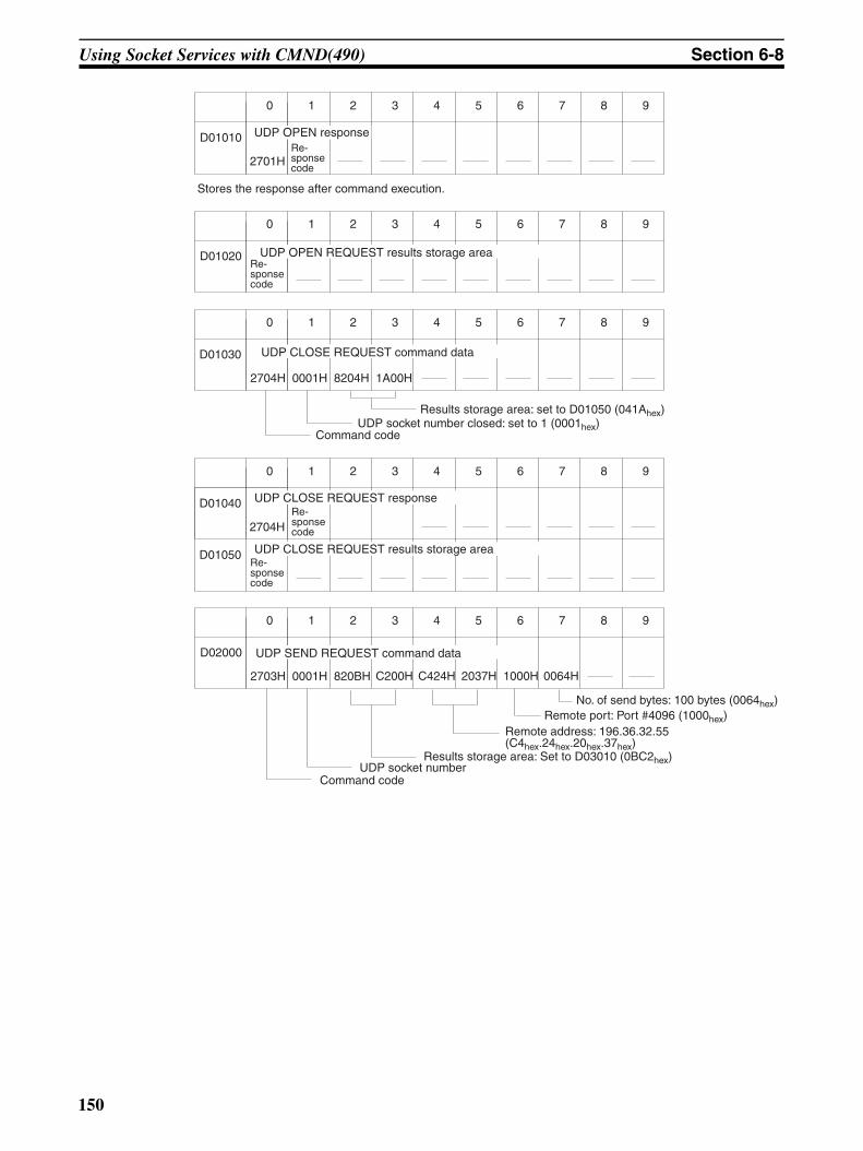
Using Socket Services with CMND(490) Section 6-8
2701H
0 1 2 3 4 5 6 7 8 9
D01010Re-sponse code
Stores the response after command execution.
UDP OPEN response
0 1 2 3 4 5 6 7 8 9
D01020 UDP OPEN REQUEST results storage areaRe-sponse code
2704H 0001H 8204H 1A00H
0 1 2 3 4 5 6 7 8 9
D01030 UDP CLOSE REQUEST command data
Command codeUDP socket number closed: set to 1 (0001hex)
Results storage area: set to D01050 (041Ahex)
2704H
0 1 2 3 4 5 6 7 8 9
D01040
D01050
UDP CLOSE REQUEST responseRe-sponse code
Re-sponse code
UDP CLOSE REQUEST results storage area
2703H 0001H 820BH C200H
0 1 2 3 4 5 6 7 8 9
D02000
C424H
UDP SEND REQUEST command data
Command codeUDP socket number
2037H 1000H 0064H
Results storage area: Set to D03010 (0BC2hex)
Remote address: 196.36.32.55 (C4hex.24hex.20hex.37hex)
Remote port: Port #4096 (1000hex)No. of send bytes: 100 bytes (0064hex)
150
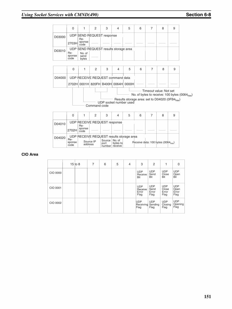
Using Socket Services with CMND(490) Section 6-8
CIO Area
2702H 0001H 820FH B400H
0 1 2 3 4 5 6 7 8 9
D04000
2703H
0 1 2 3 4 5 6 7 8 9
D03000
D03010
0064H 0000H
UDP SEND REQUEST responseRe-sponse code
Re-sponse code
UDP SEND REQUEST results storage area
UDP RECEIVE REQUEST command data
No. of bytes to receive: 100 bytes (0064hex)Timeout value: Not set
Command codeUDP socket number used
Results storage area: set to D04020 (0FB4hex)
No. of send bytes
2702H
0 1 2 3 4 5 6 7 8 9
D04010
D04020
UDP RECEIVE REQUEST responseRe-sponse code
Re-sponse code
UDP RECEIVE REQUEST results storage area
Source IP address
Source port number
No. of bytes to receive
Receive data: 100 bytes (0064hex)
7 6 5 4 3 2 1 0
CIO 0000
CIO 0001
15 to 8
CIO 0002
UDP Send Bit
UDPClose Bit
UDPOpen Bit
UDPReceive Error Flag
UDPSend Error Flag
UDPClose Error Flag
UDPOpen Error Flag
UDPReceiving Flag
UDPSending Flag
UDPClosing Flag
UDPOpening Flag
UDP Receive Bit
151
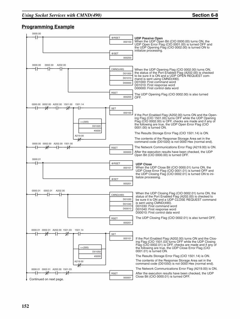
Using Socket Services with CMND(490) Section 6-8
Programming Example
If the Port Enabled Flag (A202.00) turns ON and the Clos-ing Flag (CIO 1501.03) turns OFF while the UDP Closing Flag (CIO 0002.01) is OFF, checks are made and if any of the following are true, the UDP Close Error Flag (CIO 0001.01) is turned ON.
The Results Storage Error Flag (CIO 1501.14) is ON.The contents of the Response Storage Area set in the command code (D01050) is not 0000 Hex (normal end).
The Network Communications Error Flag (A219.00) is ON.
After the execution results have been checked, the UDP Close Bit (CIO 0000.01) is turned OFF.
When the UDP Closing Flag (CIO 0002.01) turns ON, the status of the Port Enabled Flag (A202.00) is checked to be sure it is ON and a UDP CLOSE REQUEST command is sent using CMND(490).D01030: First command wordD01040: First response wordD00010: First control data word
The UDP Closing Flag (CIO 0002.01) is also turned OFF.
UDP CloseWhen the UDP Close Bit (CIO 0000.01) turns ON, the UDP Close Error Flag (CIO 0001.01) is turned OFF and the UDP Closing Flag (CIO 0002.01) is turned ON to ini-tialize processing.
If the Port Enabled Flag (A202.00) turns ON and the Open-ing Flag (CIO 1501.00) turns OFF while the UDP Opening Flag (CIO 0002.00) is OFF, checks are made and if any of the following are true, the UDP Open Error Flag (CIO 0001.00) is turned ON.
The Results Storage Error Flag (CIO 1501.14) is ON.
The contents of the Response Storage Area set in the command code (D01020) is not 0000 Hex (normal end).
The Network Communications Error Flag (A219.00) is ON.
After the execution results have been checked, the UDP Open Bit (CIO 0000.00) is turned OFF.
When the UDP Opening Flag (CIO 0002.00) turns ON, the status of the Port Enabled Flag (A202.00) is checked to be sure it is ON and a UDP OPEN REQUEST com-mand is sent using CMND(490).D01000: First command wordD01010: First response wordD00000: First control data word
The UDP Opening Flag (CIO 0002.00) is also turned OFF.
UDP Passive OpenWhen the UDP Open Bit (CIO 0000.00) turns ON, the UDP Open Error Flag (CIO 0001.00) is turned OFF and the UDP Opening Flag (CIO 0002.00) is turned ON to initialize processing.
Continued on next page.
0002.00
CMND(490)
@RSET
0000.00
@SET
0000.00 0002.00 A202.00
RSET
SET
0000.00 A202.00 1501.00 1501.14
<>(305)
A219.00
0002.00
RSET
0000.00 A202.00 1501.00
0002.01
CMND(490)
@RSET
0000.01
@SET
0000.01 0002.01 A202.00
RSET
SET
0000.01 A202.00 1501.03 1501.14
<>(305)
A219.00
0002.01
RSET
0000.01 A202.00 1501.03
000100
000200
D01000
D01010
D00000
000200
000100
D01020
#0000
000000
000101
000201
D01030
D01040
D00010
000201
000101
D01050
#0000
000001
152
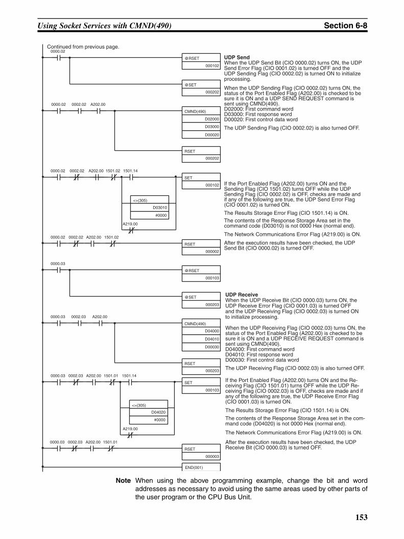
Using Socket Services with CMND(490) Section 6-8
Note When using the above programming example, change the bit and wordaddresses as necessary to avoid using the same areas used by other parts ofthe user program or the CPU Bus Unit.
When the UDP Receiving Flag (CIO 0002.03) turns ON, the status of the Port Enabled Flag (A202.00) is checked to be sure it is ON and a UDP RECEIVE REQUEST command is sent using CMND(490).D04000: First command wordD04010: First response wordD00030: First control data word
The UDP Receiving Flag (CIO 0002.03) is also turned OFF.
UDP ReceiveWhen the UDP Receive Bit (CIO 0000.03) turns ON, the UDP Receive Error Flag (CIO 0001.03) is turned OFF and the UDP Receiving Flag (CIO 0002.03) is turned ON to initialize processing.
When the UDP Sending Flag (CIO 0002.02) turns ON, the status of the Port Enabled Flag (A202.00) is checked to be sure it is ON and a UDP SEND REQUEST command is sent using CMND(490).D02000: First command wordD03000: First response wordD00020: First control data word
The UDP Sending Flag (CIO 0002.02) is also turned OFF.
UDP SendWhen the UDP Send Bit (CIO 0000.02) turns ON, the UDP Send Error Flag (CIO 0001.02) is turned OFF and the UDP Sending Flag (CIO 0002.02) is turned ON to initialize processing.
If the Port Enabled Flag (A202.00) turns ON and the Sending Flag (CIO 1501.02) turns OFF while the UDP Sending Flag (CIO 0002.02) is OFF, checks are made and if any of the following are true, the UDP Send Error Flag (CIO 0001.02) is turned ON.
The Results Storage Error Flag (CIO 1501.14) is ON.The contents of the Response Storage Area set in the command code (D03010) is not 0000 Hex (normal end).
The Network Communications Error Flag (A219.00) is ON.
After the execution results have been checked, the UDP Send Bit (CIO 0000.02) is turned OFF.
If the Port Enabled Flag (A202.00) turns ON and the Re-ceiving Flag (CIO 1501.01) turns OFF while the UDP Re-ceiving Flag (CIO 0002.03) is OFF, checks are made and if any of the following are true, the UDP Receive Error Flag (CIO 0001.03) is turned ON.
The Results Storage Error Flag (CIO 1501.14) is ON.
The contents of the Response Storage Area set in the com-mand code (D04020) is not 0000 Hex (normal end).
The Network Communications Error Flag (A219.00) is ON.
After the execution results have been checked, the UDP Receive Bit (CIO 0000.03) is turned OFF.
Continued from previous page.
0002.02
CMND(490)
@RSET
0000.02
@SET
0000.02 0002.02 A202.00
RSET
SET
0000.02 A202.00 1501.02 1501.14
<>(305)
A219.00
0002.02
RSET
0000.02 A202.00 1501.02
0002.03
CMND(490)
@RSET
0000.03
@SET
0000.03 0002.03 A202.00
RSET
SET
0000.03 A202.00 1501.01 1501.14
<>(305)
A219.00
0002.03
RSET
0000.03 A202.00 1501.01
END(001)
000102
000202
D02000
D03000
D00020
000202
000102
D03010
#0000
000002
000103
000203
D04000
D04010
D00030
000203
000103
D04020
#0000
000003
153
Precautions in Using Socket Services Section 6-9
6-9 Precautions in Using Socket Services
6-9-1 UDP and TCP Socket Services• If a short response monitor time is specified in CMND(490) control data
and the Ethernet Unit is operating under a high load, a result may bestored even if the response code indicates a time-out. If this occurs,increase the monitor time specified with CMND(490).
• The socket status area in the CIO Area is zeroed when the PLC’s operat-ing mode is changed (e.g., from PROGRAM to RUN). The actual EthernetUnit socket status, however, will remain unchanged after the socket statusarea is zeroed. To avoid this problem, use the IOM Hold setting in the PLCSetup. Refer to the PLC’s operation manuals for details on settings.
• The Results Storage Error Flag will turn ON in the socket status to indi-cate that the specified Results Storage Area does not exist in the PLC.Correct the user program.
• Communications time may increase if multiple Ethernet Unit functions areused simultaneously or due to the contents of the user program.
• Communications efficiency may decrease due to high communicationsloads on the network.
• All data is flushed from the socket’s communications buffer when a socketis closed with the CLOSE REQUEST command. In some cases, thetransmit data for the SEND REQUEST command issued just before thesocket was closed may not be sent.
• When sockets are open, the Ethernet Unit provides a 4,096-byte buffer foreach TCP socket and 9,016-byte buffer for each UDP socket to allow datato be received at any time. These buffers are shared by all open sockets.Receive data will be discarded for a socket if the buffer becomes full. Theuser application must therefore issue RECEIVE REQUEST commandsfrequently enough to prevent the internal buffers from becoming full.
6-9-2 UDP Socket Service• The UDP socket sets a broadcast address for the remote node address to
broadcast data to all nodes of the network simultaneously. The maximumlength of broadcast data is 1,472 bytes. Data in multiple fragments (over1,473 bytes for a UDP socket) cannot be broadcast.
• The UDP socket does not check the transmitted data to ensure communi-cations reliability. To increase communication reliability, communicationschecks and retries must be included in the user application program.
6-9-3 TCP Socket Service• If the TCP socket of the remote node closes (the connection is broken)
during communications, the TCP socket at the local node must also beclosed. The communications Results Storage Area can be used to checkif the connection has been broken. Close the local socket immediatelyafter detecting that the remote TCP socket has closed. The following situ-ations indicate that the remote socket has closed.
TCP Receive Results Storage Area: Response code = 004B (error at remote node)
TCP Send Results Storage Area: Response code = 0020 (connection broken with remote socket duringtransmission)
154
Precautions in Using Socket Services Section 6-9
• Data can remain in a buffer at the local node if the remote TCP socketcloses during communications. Any data remaining in the buffer will bediscarded when the TCP socket is closed. To avoid problems of thisnature, steps will have to be taken in the application program, such assending data to enable closing, and then only closing once reception ofthis data has been confirmed.
• When closing a connection for a TCP socket, the first port to be closedcannot be reopened for at least 60 seconds after the other port closes.However, this restriction does not apply for a port opened using the TCPACTIVE OPEN REQUEST command with a local TCP port number of 0(port number automatically assigned) which is closed from the side thatactively opened the socket.
• A connection is established for a passively opened socket by activelyopening it from another socket. A connection will not be established by adifferent socket attempting to actively open the socket that is alreadyactively opening a socket. Similarly, a connection will not be established ifa different socket attempts to passively open a socket that is alreadybeing passively opened by another socket. You cannot actively open mul-tiple connections to a socket passively opened at the Ethernet Unit.
• The Ethernet Unit TCP sockets have no KEEP ALIVE function to checkthat the connection is normal if communications do not occur for a settime period through a communications line for which a connection hasbeen established. The Ethernet Unit’s TCP sockets make no checks tothe socket at the other node. Checks made by the remote node, however,are received as responses, so that it is not necessary for the user pro-gram to consider the KEEP ALIVE function.
6-9-4 Precautions in Using Socket Service Request Switches• Send and reception processing can not be performed at the same time
when Socket Service Request Switches are used for socket servicesbecause there is only one Socket Service Parameter Area for eachsocket. For example, if the Send Request Switch is turned ON when datais being received, the response code will be 110C hexadecimal, indicatingthat a Request Switch was turned ON during communications processing.(The response code for the reception will overwrite this code when pro-cessing has been completed.)
• If more than one Request Switch is turned ON simultaneously, theresponse code will be 110C hexadecimal and all requested processingwill end in an error.
• Close processing can be performed, however, even during open, send, orreceive processing. This enables emergency close processing. Also, theonly parameter required for close processing is the socket number, so asocket can be closed even when parameters are set for another process.
155
Precautions in Using Socket Services Section 6-9
6-9-5 Times Required for Sending and Receiving for Socket ServicesThe transmission delays for socket service is calculated as the sum of thecommunications processing times for both nodes.
Transmission delay = Remote node send processing time + Local nodereceive processing time + Local node send processing time + Remotenode receive processing time
Calculate the maximum Ethernet Unit transmission delays for sending andreceiving using the following formulas. These times are the same for bothUDP and TCP.
The delays found using the following formulas, however, are approximate val-ues when one socket service is used. If multiple socket services are used, thedelays will increase depending on the operating conditions. Also, the trans-mission delay on the network relative to the processing time is so small that itcan be ignored, and so it is omitted.
Requesting UDP Socket Services by Manipulating Dedicated Control Bits
High-speed Socket Services Enabled and CPU Unit Cycle Time of Less Than 1.5 ms
Transmission processing time = reception processing time = CPU Unit cycle time × 1 + number of send/receive bytes × 0.0005 + 5.0 (ms)
High-speed Socket Services Enabled and CPU Unit Cycle Time of 1.5 ms or Greater
Transmission processing time = reception processing time = CPU Unit cycle time × 6 (ms)
High-speed Socket Services Disabled
Transmission processing time = reception processing time = CPU Unit cycle time × 7 + 40.0 (ms)
Requesting TCP Socket Services by Manipulating Dedicated Control Bits
High-speed Socket Services Enabled and CPU Unit Cycle Time of Less Than 1.5 ms
Transmission processing time = reception processing time = CPU Unit cycle time × 1 + number of send/receive bytes × 0.0005 + 6.5 (ms)
High-speed Socket Services Enabled and CPU Unit Cycle Time of 1.5 ms or Greater
Transmission processing time = reception processing time = CPU Unit cycle time × 6 (ms)
High-speed Socket Services Disabled
Transmission processing time = reception processing time = CPU Unit cycle time × 7 + 40.0 (ms)
Requesting UDP Socket Services by Executing CMND(490)
CPU Unit Cycle Time Less Than 5 ms
Transmission processing time = reception processing time = CPU Unit cycle time × 6 + 65.0 (ms)
CPU Unit Cycle Time between 5 ms Inclusive and 10 ms Exclusive
Transmission processing time = reception processing time = 120.0 (ms)
156
Precautions in Using Socket Services Section 6-9
CPU Unit Cycle Time of 10 ms or Greater
Transmission processing time = reception processing time = CPU Unit cycle time × 4 (ms)
TCP Socket Services Using CMND(490)
CPU Unit Cycle Time Less Than 5 ms
Transmission processing time = reception processing time = CPU Unit cycle time × 6 + 70.0 (ms)
CPU Unit Cycle Time between 5 ms Inclusive and 10 ms Exclusive
Transmission processing time = reception processing time = 120.0 (ms)
CPU Unit Cycle Time of 10 ms or Greater
Transmission processing time = reception processing time = CPU Unit cycle time × 4 (ms)
Note 1. The values obtained from the above equations are guidelines for the trans-mission delay time when one socket in the Ethernet Unit is used only. Theexecution time required for the user program is not included.
2. The communications time for the remote nodes depends on the device be-ing used. For remote nodes that are not Ethernet Units, calculate the com-munications time according to the device's operation manual.
3. The actual operating environment can cause transmission delays largerthan those calculated with the methods given here. Among the causes oflonger delays are the following: traffic on the network, window sizes at net-work nodes, traffic through the Ethernet Unit (e.g., simultaneous servicingof multiple sockets and socket service communications, etc.), and the sys-tem configuration.
4. The above values are guidelines when the default (4%) for the uniform pe-ripheral servicing time in the PLC Setup is used.
5. By increasing the value of the uniform peripheral servicing time, the maxi-mum transmission delay time for socket services can be shorter.
6. If the high-speed socket service option is selected and manipulating spe-cific bits is used, the setting for the peripheral servicing time will not affectthe time required for communications. This is because the send process-ing or receive processing, which previously depended on the peripheralservicing time, are not interrupted.
7. Processing cannot be faster than the send and receive processing perfor-mance of the Ethernet Unit if the send request is processed periodicallyusing a ladder program timer or if receive request processing is performedfor continuous data from a remote node. In particular, the data buffer on thereceiving side may be exhausted. In such a case, adjust the send timing(i.e., send timing from remote node) or receive frequency so that the actualload is approximately 1.5 times slower than the processing performance.
Example: When using TCP socket services between two PLCs by manipu-lating specific bits (high-speed socket service enabled) to send/receive 512 bytes in both directions, the guideline for the maxi-mum transmission delay time can be calculated according to thefollowing conditions as shown in the table below.
CPU Unit cycle time (local node) = 1 ms
157
Precautions in Using Socket Services Section 6-9
CPU Unit cycle time (remote node) = 4 ms
Item Calculation
Reception processing time (local node)
1 × 1 + 512 × 0.0005 + 6.5 = 6.756 ms ≈ 6.8 ms
Transmission processing time (local node)
1 × 1 + 512 × 0.0005 + 6.5 = 6.756 ms ≈ 6.8 ms
Transmission processing time (remote node)
4 × 6 = 24.0 ms
Reception processing time (remote node)
4 × 6 = 24.0 ms
Maximum transmission delay
6.8 + 6.8 + 24.0 + 24.0 = 61.6 ms
158
SECTION 7Using FINS Communications to Create Host Applications
This section provides information on communicating on Ethernet Systems and interconnected networks using FINScommands. The information provided in the section deals only with FINS communications in reference to Ethernet Units.
FINS commands issued from a PLC are sent via the SEND(090), RECV(098), and CMND(490) instructions programmedinto the user ladder-diagram program. Refer to the CS/CJ-series Programmable Controllers Instructions Reference Manual(W340) for further details on programming these instructions.
7-1 Overview of FINS Communications. . . . . . . . . . . . . . . . . . . . . . . . . . . . . . . . 160
7-1-1 Communications On an Ethernet Network. . . . . . . . . . . . . . . . . . . . 160
7-1-2 Using the FINS/UDP and FINS/TCP Methods . . . . . . . . . . . . . . . . 161
7-1-3 FINS Communications Service Specifications for Ethernet . . . . . . 161
7-2 FINS Frames . . . . . . . . . . . . . . . . . . . . . . . . . . . . . . . . . . . . . . . . . . . . . . . . . . 162
7-3 FINS/UDP Method . . . . . . . . . . . . . . . . . . . . . . . . . . . . . . . . . . . . . . . . . . . . . 163
7-3-1 Overview. . . . . . . . . . . . . . . . . . . . . . . . . . . . . . . . . . . . . . . . . . . . . . 163
7-3-2 Sending Commands from a Host Computer. . . . . . . . . . . . . . . . . . . 166
7-4 FINS/TCP Method . . . . . . . . . . . . . . . . . . . . . . . . . . . . . . . . . . . . . . . . . . . . . 171
7-4-1 Overview. . . . . . . . . . . . . . . . . . . . . . . . . . . . . . . . . . . . . . . . . . . . . . 171
7-4-2 FINS/TCP Mode Specifications . . . . . . . . . . . . . . . . . . . . . . . . . . . . 177
7-4-3 Sending Commands from a Host Computer. . . . . . . . . . . . . . . . . . . 184
7-5 Maximum Transmission Delays: Writing/Reading to CPU Unit . . . . . . . . . . 192
159
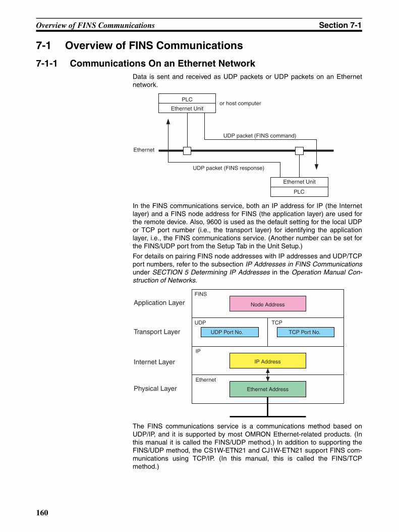
Overview of FINS Communications Section 7-1
7-1 Overview of FINS Communications
7-1-1 Communications On an Ethernet NetworkData is sent and received as UDP packets or UDP packets on an Ethernetnetwork.
In the FINS communications service, both an IP address for IP (the Internetlayer) and a FINS node address for FINS (the application layer) are used forthe remote device. Also, 9600 is used as the default setting for the local UDPor TCP port number (i.e., the transport layer) for identifying the applicationlayer, i.e., the FINS communications service. (Another number can be set forthe FINS/UDP port from the Setup Tab in the Unit Setup.)
For details on pairing FINS node addresses with IP addresses and UDP/TCPport numbers, refer to the subsection IP Addresses in FINS Communicationsunder SECTION 5 Determining IP Addresses in the Operation Manual Con-struction of Networks.
The FINS communications service is a communications method based onUDP/IP, and it is supported by most OMRON Ethernet-related products. (Inthis manual it is called the FINS/UDP method.) In addition to supporting theFINS/UDP method, the CS1W-ETN21 and CJ1W-ETN21 support FINS com-munications using TCP/IP. (In this manual, this is called the FINS/TCPmethod.)
UDP packet (FINS command)
Ethernet
UDP packet (FINS response)
Ethernet Unit
PLC
PLC
Ethernet Unitor host computer
FINS
UDP TCP
IP
Ethernet
Ethernet Address
Node AddressApplication Layer
Transport Layer
Internet Layer
Physical Layer
IP Address
UDP Port No. TCP Port No.
160
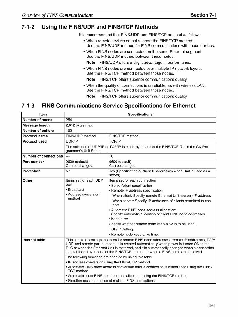
Overview of FINS Communications Section 7-1
7-1-2 Using the FINS/UDP and FINS/TCP MethodsIt is recommended that FINS/UDP and FINS/TCP be used as follows:
• When remote devices do not support the FINS/TCP method:Use the FINS/UDP method for FINS communications with those devices.
• When FINS nodes are connected on the same Ethernet segment:Use the FINS/UDP method between those nodes.
Note FINS/UDP offers a slight advantage in performance.
• When FINS nodes are connected over multiple IP network layers:Use the FINS/TCP method between those nodes.
Note FINS/TCP offers superior communications quality.
• When the quality of connections is unreliable, as with wireless LAN:Use the FINS/TCP method between those nodes.
Note FINS/TCP offers superior communications quality.
7-1-3 FINS Communications Service Specifications for Ethernet Item Specifications
Number of nodes 254
Message length 2,012 bytes max.
Number of buffers 192
Protocol name FINS/UDP method FINS/TCP method
Protocol used UDP/IP TCP/IP
The selection of UDP/IP or TCP/IP is made by means of the FINS/TCP Tab in the CX-Pro-grammer's Unit Setup.
Number of connections --- 16
Port number 9600 (default)Can be changed.
9600 (default)Can be changed.
Protection No Yes (Specification of client IP addresses when Unit is used as a server)
Other Items set for each UDP port• Broadcast• Address conversion
method
Items set for each connection• Server/client specification• Remote IP address specification
When client: Specify remote Ethernet Unit (server) IP address
When server: Specify IP addresses of clients permitted to con-nect
• Automatic FINS node address allocation:Specify automatic allocation of client FINS node addresses
• Keep-aliveSpecify whether remote node keep-alive is to be used.TCP/IP Setting:
• Remote node keep-alive time.
Internal table This a table of correspondences for remote FINS node addresses, remote IP addresses, TCP/UDP, and remote port numbers. It is created automatically when power is turned ON to the PLC or when the Ethernet Unit is restarted, and it is automatically changed when a connection is established by means of the FINS/TCP method or when a FINS command received.The following functions are enabled by using this table.
• IP address conversion using the FINS/UDP method• Automatic FINS node address conversion after a connection is established using the FINS/
TCP method• Automatic client FINS node address allocation using the FINS/TCP method• Simultaneous connection of multiple FINS applications
161
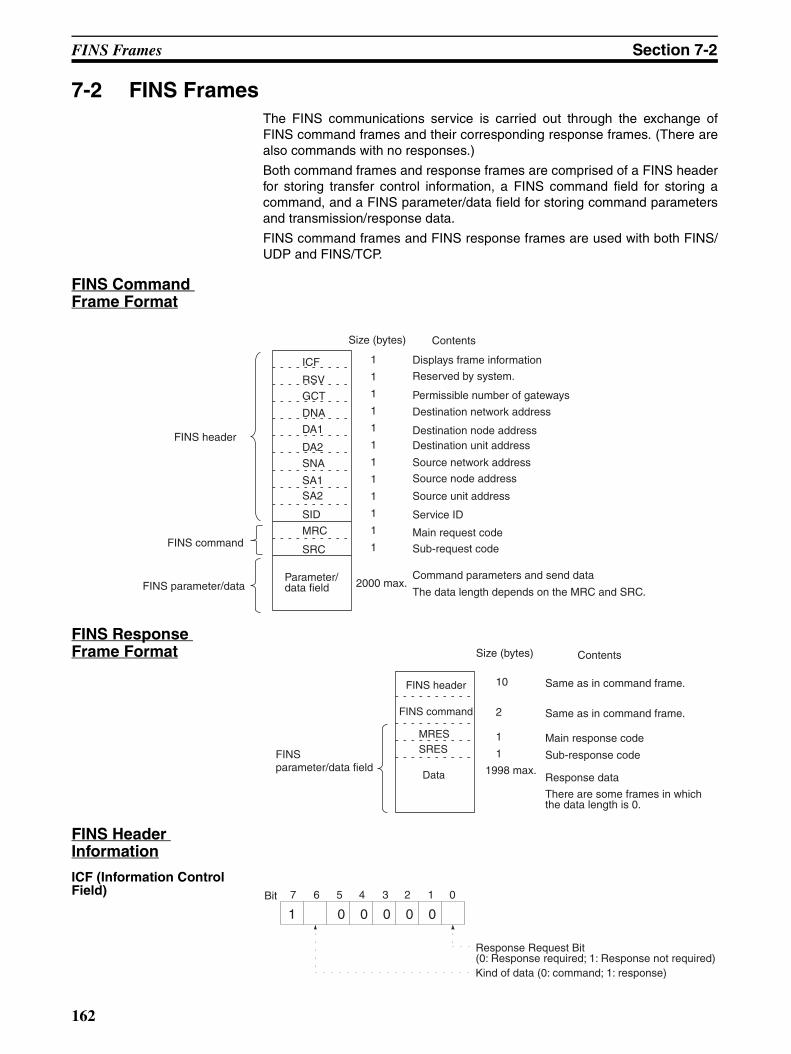
FINS Frames Section 7-2
7-2 FINS FramesThe FINS communications service is carried out through the exchange ofFINS command frames and their corresponding response frames. (There arealso commands with no responses.)
Both command frames and response frames are comprised of a FINS headerfor storing transfer control information, a FINS command field for storing acommand, and a FINS parameter/data field for storing command parametersand transmission/response data.
FINS command frames and FINS response frames are used with both FINS/UDP and FINS/TCP.
FINS Command Frame Format
FINS Response Frame Format
FINS Header Information
ICF (Information Control Field)
FINS header
FINS command
FINS parameter/dataParameter/data field
Size (bytes) Contents
Displays frame information
Reserved by system.
Permissible number of gateways
Destination network address
Destination node addressDestination unit address
Source network address
Source node address
Source unit address
Service ID
Main request code
Sub-request code
2000 max.Command parameters and send data
The data length depends on the MRC and SRC.
1
1
1
1
1
1
1
1
1
1
1
1
ICF
RSV
GCT
DNA
DA1
DA2
SNA
SA1SA2
SID
MRC
SRC
FINS parameter/data field
FINS header
FINS command
Data
Size (bytes) Contents
Same as in command frame.
Same as in command frame.
Main response code
Sub-response code1998 max.
Response data
There are some frames in which the data length is 0.
10
2
1
1
MRESSRES
7 6 5 4 3 2 1 0
1 0 0 0 0 0Bit
Response Request Bit (0: Response required; 1: Response not required)Kind of data (0: command; 1: response)
162
FINS/UDP Method Section 7-3
RSV (Reserved by System)
Set to 00 (Hex).
GCT (Permissible Number of Gateways)
Set to 02 (Hex).
DNA (Destination Network Address)
Specifies the number of the network where the destination node is located.The address can be specified in the following range.00 (Hex): Local network01 to 7F (Hex): Destination network address (1 to 127)
DA1 (Destination Node Address
Specifies the number of the node where the command is being sent. Thisnode address is the address used for FINS, and is different from the IPaddress used for Ethernet.
00 (Hex): Local PLC Unit01 to FE (Hex): Destination node address (1 to 254)FF (Hex): Broadcasting
When multiple Communications Units are mounted, DA1 specifies the nodeaddress of the Unit connected to the network specified by DNA.
DA2 (Destination Unit Address)
Specifies the number of the Unit at the destination node.00 (Hex): PLC (CPU Unit)10 to 1F (Hex): CPU Bus Unit unit numbers 0 to15 (16 to 31)E1 (Hex): Inner BoardFE (Hex): Unit connected to network.
SNA (Source Network Address)
Specifies the number of the network where the local node is located. Theranges of numbers that can be specified are the same as for DNA.
SA1 (Source Node Address)
Specifies the local node address. The ranges of numbers that can be speci-fied are the same as for DA1.
SA1 (Source Unit Address)
Specifies the number of the Unit at the local node.The ranges of numbers thatcan be specified are the same as for DA2.
SID (Service ID) The SID is used to identify the process that data is sent from. Any number canbe set between 00 to FF hexadecimal for the SID. The same value set for theSID in the command is returned by the node sending the response, allowingcommands and responses to be matched when commands are sent in suc-cession to the same Unit.
7-3 FINS/UDP Method
7-3-1 Overview
FINS/UDP Features The FINS/UDP method is a FINS communications method that uses the UDP/IP protocol. UDP/IP is a connectionless communications protocol. When amessage is sent from one node to another, the two nodes have an equal rela-tionship and there is no clear connection. If using TCP is like making a tele-phone call, then UDP is more like delivering a memo by hand. Although theUDP protocol is fast, data communications are less reliable than with TCP.
In particular, when sending large amounts of data involving significant routing,the user must program measures, such as retries, into applications in order toimprove reliability.
163
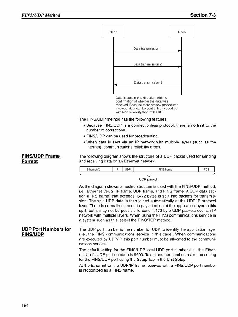
FINS/UDP Method Section 7-3
The FINS/UDP method has the following features:
• Because FINS/UDP is a connectionless protocol, there is no limit to thenumber of corrections.
• FINS/UDP can be used for broadcasting.
• When data is sent via an IP network with multiple layers (such as theInternet), communications reliability drops.
FINS/UDP Frame Format
The following diagram shows the structure of a UDP packet used for sendingand receiving data on an Ethernet network.
As the diagram shows, a nested structure is used with the FINS/UDP method,i.e., Ethernet Ver. 2, IP frame, UDP frame, and FINS frame. A UDP data sec-tion (FINS frame) that exceeds 1,472 bytes is split into packets for transmis-sion. The split UDP data is then joined automatically at the UDP/IP protocollayer. There is normally no need to pay attention at the application layer to thissplit, but it may not be possible to send 1,472-byte UDP packets over an IPnetwork with multiple layers. When using the FINS communications service ina system such as this, select the FINS/TCP method.
UDP Port Numbers for FINS/UDP
The UDP port number is the number for UDP to identify the application layer(i.e., the FINS communications service in this case). When communicationsare executed by UDP/IP, this port number must be allocated to the communi-cations service.
The default setting for the FINS/UDP local UDP port number (i.e., the Ether-net Unit's UDP port number) is 9600. To set another number, make the settingfor the FINS/UDP port using the Setup Tab in the Unit Setup.
At the Ethernet Unit, a UDP/IP frame received with a FINS/UDP port numberis recognized as a FINS frame.
Node Node
Data transmission 1
Data transmission 2
Data transmission 3
Data is sent in one direction, with no confirmation of whether the data was received. Because there are few procedures involved, data can be sent at high speed but with less reliability than with TCP.
EthernetV.2 IP UDP FINS frame FCS
UDP packet
164
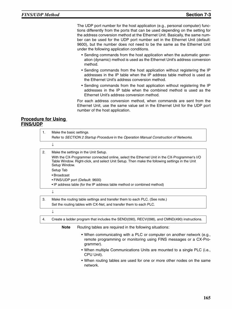
FINS/UDP Method Section 7-3
The UDP port number for the host application (e.g., personal computer) func-tions differently from the ports that can be used depending on the setting forthe address conversion method at the Ethernet Unit. Basically, the same num-ber can be used for the UDP port number set in the Ethernet Unit (default:9600), but the number does not need to be the same as the Ethernet Unitunder the following application conditions.
• Sending commands from the host application when the automatic gener-ation (dynamic) method is used as the Ethernet Unit’s address conversionmethod.
• Sending commands from the host application without registering the IPaddresses in the IP table when the IP address table method is used asthe Ethernet Unit’s address conversion method.
• Sending commands from the host application without registering the IPaddresses in the IP table when the combined method is used as theEthernet Unit’s address conversion method.
For each address conversion method, when commands are sent from theEthernet Unit, use the same value set in the Ethernet Unit for the UDP portnumber of the host application.
Procedure for Using FINS/UDP
Note Routing tables are required in the following situations:
• When communicating with a PLC or computer on another network (e.g.,remote programming or monitoring using FINS messages or a CX-Pro-grammer).
• When multiple Communications Units are mounted to a single PLC (i.e.,CPU Unit).
• When routing tables are used for one or more other nodes on the samenetwork.
1. Make the basic settings.Refer to SECTION 2 Startup Procedure in the Operation Manual Construction of Networks.
↓
2. Make the settings in the Unit Setup.With the CX-Programmer connected online, select the Ethernet Unit in the CX-Programmer's I/O Table Window. Right-click, and select Unit Setup. Then make the following settings in the Unit Setup Window.Setup Tab
• Broadcast• FINS/UDP port (Default: 9600)• IP address table (for the IP address table method or combined method)
↓
3. Make the routing table settings and transfer them to each PLC. (See note.)
Set the routing tables with CX-Net, and transfer them to each PLC.
↓
4. Create a ladder program that includes the SEND(090), RECV(098), and CMND(490) instructions.
165
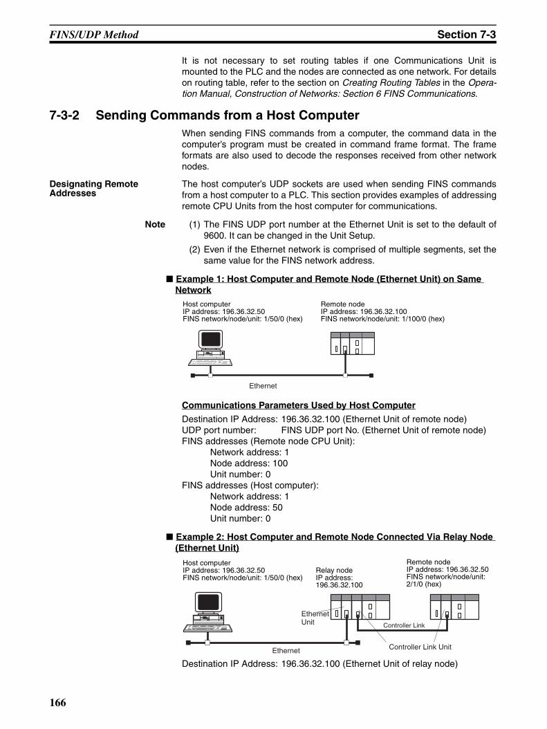
FINS/UDP Method Section 7-3
It is not necessary to set routing tables if one Communications Unit ismounted to the PLC and the nodes are connected as one network. For detailson routing table, refer to the section on Creating Routing Tables in the Opera-tion Manual, Construction of Networks: Section 6 FINS Communications.
7-3-2 Sending Commands from a Host ComputerWhen sending FINS commands from a computer, the command data in thecomputer’s program must be created in command frame format. The frameformats are also used to decode the responses received from other networknodes.
Designating Remote Addresses
The host computer’s UDP sockets are used when sending FINS commandsfrom a host computer to a PLC. This section provides examples of addressingremote CPU Units from the host computer for communications.
Note (1) The FINS UDP port number at the Ethernet Unit is set to the default of9600. It can be changed in the Unit Setup.
(2) Even if the Ethernet network is comprised of multiple segments, set thesame value for the FINS network address.
Example 1: Host Computer and Remote Node (Ethernet Unit) on Same Network
Communications Parameters Used by Host Computer
Destination IP Address: 196.36.32.100 (Ethernet Unit of remote node)UDP port number: FINS UDP port No. (Ethernet Unit of remote node)FINS addresses (Remote node CPU Unit):
Network address: 1Node address: 100Unit number: 0
FINS addresses (Host computer):Network address: 1Node address: 50Unit number: 0
Example 2: Host Computer and Remote Node Connected Via Relay Node (Ethernet Unit)
Destination IP Address: 196.36.32.100 (Ethernet Unit of relay node)
Ethernet
Host computerIP address: 196.36.32.50FINS network/node/unit: 1/50/0 (hex)
Remote nodeIP address: 196.36.32.100FINS network/node/unit: 1/100/0 (hex)
Controller Link
Ethernet
Ethernet Unit
Controller Link Unit
Host computerIP address: 196.36.32.50FINS network/node/unit: 1/50/0 (hex)
Remote nodeIP address: 196.36.32.50FINS network/node/unit: 2/1/0 (hex)
Relay nodeIP address: 196.36.32.100
166
FINS/UDP Method Section 7-3
UDP port number: FINS UDP port number (Ethernet Unit of relay node)FINS addresses (Remote node CPU Unit):
Network address: 2Node address: 1Unit number: 0
FINS addresses (Host computer):Network address: 1Node address: 50Unit number: 0
FINS/UDP Sample Program
Operation Overview • This program reads 150 words of the PLC memory beginning at D00100by sending a FINS command (MEMORY AREA READ, command code0101) from a UNIX workstation (WS) to the PLC on the Ethernet network.
• If no response is received within two seconds of sending the FINS com-mand, the command will be resent.
Settings • The Ethernet Unit IP address is 196.36.32.100, and the FINS nodeaddress is 100. IP address conversion is set to automatic generation(dynamic).
• The FINS UDP port number for the Ethernet Unit is 9600 (default).
• The workstation’s IP address is 196.36.32.50 and its FINS node addressis 50.
• The FINS UDP port number for the workstation can be a user-set number(if set to 0, the system automatically allocates an available port).
167
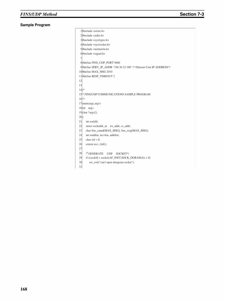
FINS/UDP Method Section 7-3
Sample Program
1 #include <errno.h>
2 #include <stdio.h>
3 #include <sys/types.h>
4 #include <sys/socket.h>
5 #include <netinet/in.h>
6 #include <signal.h>
7
8 #define FINS_UDP_PORT 9600
9 #define SERV_IP_ADDR "196.36.32.100" /* Ethernet Unit IP ADDRESS*/
10 #define MAX_MSG 2010
11 #define RESP_TIMEOUT 2
12
13
14 /*
15 * FINS/UDP COMMUNICATIONS SAMPLE PROGRAM
16 */
17 main(argc,argv)
18 int argc;
19 char *argv[];
20
21 int sockfd;
22 struct sockaddr_in ws_addr, cs_addr;
23 char fins_cmnd[MAX_MSG], fins_resp[MAX_MSG];
24 int sendlen, recvlen, addrlen;
25 char sid = 0;
26 extern recv_fail();
27
28 /* GENERATE UDP SOCKET*/
29 if ((sockfd = socket(AF_INET,SOCK_DGRAM,0)) < 0)
30 err_exit("can't open datagram socket");
31
168
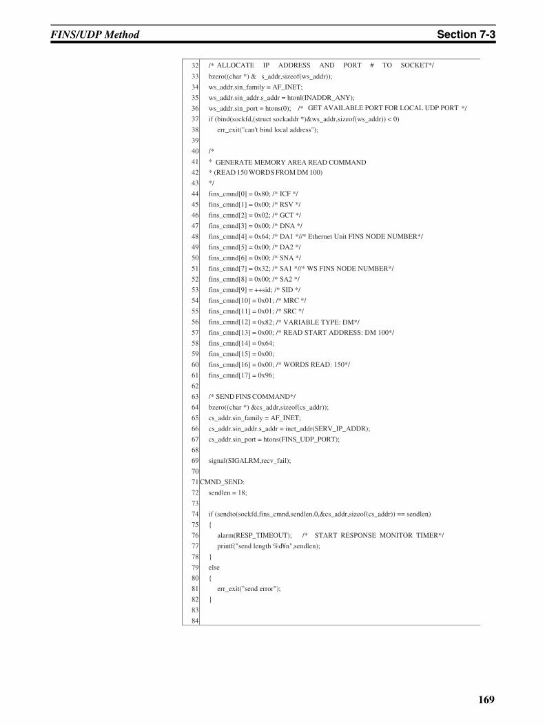
FINS/UDP Method Section 7-3
32 /*
33 bzero((char *) & s_addr,sizeof(ws_addr));
34 ws_addr.sin_family = AF_INET;
35 ws_addr.sin_addr.s_addr = htonl(INADDR_ANY);
36 ws_addr.sin_port = htons(0); /* GET AVAILABLE PORT FOR LOCAL UDP PORT */
37 if (bind(sockfd,(struct sockaddr *)&ws_addr,sizeof(ws_addr)) < 0)
38 err_exit("can't bind local address");
39
40 /*
41 *
42 * (READ 150 WORDS FROM DM 100)
43 */
44 fins_cmnd[0] = 0x80; /* ICF */
45 fins_cmnd[1] = 0x00; /* RSV */
46 fins_cmnd[2] = 0x02; /* GCT */
47 fins_cmnd[3] = 0x00; /* DNA */
48 fins_cmnd[4] = 0x64; /* DA1 *//* Ethernet Unit FINS NODE NUMBER*/
49 fins_cmnd[5] = 0x00; /* DA2 */
50 fins_cmnd[6] = 0x00; /* SNA */
51 fins_cmnd[7] = 0x32; /* SA1 *//* WS FINS NODE NUMBER*/
52 fins_cmnd[8] = 0x00; /* SA2 */
53 fins_cmnd[9] = ++sid; /* SID */
54 fins_cmnd[10] = 0x01; /* MRC */
55 fins_cmnd[11] = 0x01; /* SRC */
56 fins_cmnd[12] = 0x82; /* VARIABLE TYPE: DM*/
57 fins_cmnd[13] = 0x00; /* READ START ADDRESS: DM 100*/
58 fins_cmnd[14] = 0x64;
59 fins_cmnd[15] = 0x00;
60 fins_cmnd[16] = 0x00; /* WORDS READ: 150*/
61 fins_cmnd[17] = 0x96;
62
63 /* SEND FINS COMMAND*/
64 bzero((char *) &cs_addr,sizeof(cs_addr));
65 cs_addr.sin_family = AF_INET;
66 cs_addr.sin_addr.s_addr = inet_addr(SERV_IP_ADDR);
67 cs_addr.sin_port = htons(FINS_UDP_PORT);
68
69 signal(SIGALRM,recv_fail);
70
71 CMND_SEND:
72 sendlen = 18;
73
74 if (sendto(sockfd,fins_cmnd,sendlen,0,&cs_addr,sizeof(cs_addr)) == sendlen)
75
76 alarm(RESP_TIMEOUT); /* START RESPONSE MONITOR TIMER*/
77 printf("send length %d¥n",sendlen);
78
79 else
80
81 err_exit("send error");
82
83
84
ALLOCATE IP ADDRESS AND PORT # TO SOCKET*/
GENERATE MEMORY AREA READ COMMAND
169
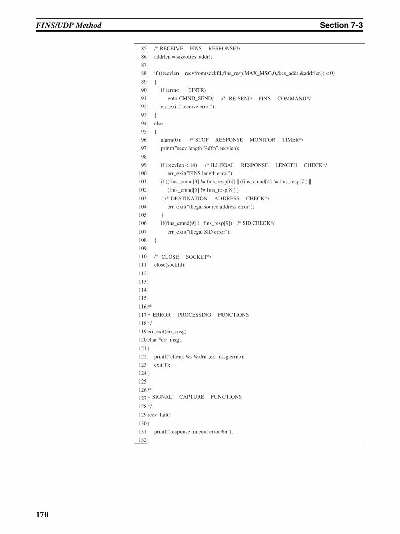
FINS/UDP Method Section 7-3
85 /* RECEIVE FINS RESPONSE*/
86 addrlen = sizeof(cs_addr);
87
88 if ((recvlen = recvfrom(sockfd,fins_resp,MAX_MSG,0,&cs_addr,&addrlen)) < 0)
89
90 if (errno == EINTR)
91 goto CMND_SEND; /*
92 err_exit("receive error");
93
94 else
95
96 alarm(0); /*
97 printf("recv length %d¥n",recvlen);
98
99 if (recvlen < 14) /*
100 err_exit("FINS length error");
101 if ((fins_cmnd[3] != fins_resp[6]) || (fins_cmnd[4] != fins_resp[7]) ||
102 (fins_cmnd[5] != fins_resp[8]) )
103 /*
104 err_exit("illegal source address error");
105
106 if(fins_cmnd[9] != fins_resp[9]) /* SID CHECK*/
107 err_exit("illegal SID error");
108
109
110 /*
111 close(sockfd);
112
113
114
115
116 /*
117 *
118 */
119 err_exit(err_msg)
120 char *err_msg;
121
122 printf("client: %s %x¥n",err_msg,errno);
123 exit(1);
124
125
126 /*
127 *
128 */
129 recv_fail()
130
131 printf("response timeout error ¥n");
132
RE-SEND FINS COMMAND*/
STOP RESPONSE MONITOR TIMER*/
ILLEGAL RESPONSE LENGTH CHECK*/
DESTINATION ADDRESS CHECK*/
CLOSE SOCKET*/
ERROR PROCESSING FUNCTIONS
SIGNAL CAPTURE FUNCTIONS
170
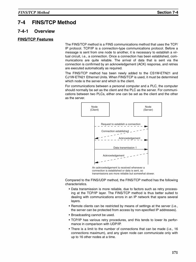
FINS/TCP Method Section 7-4
7-4 FINS/TCP Method
7-4-1 Overview
FINS/TCP FeaturesThe FINS/TCP method is a FINS communications method that uses the TCP/IP protocol. TCP/IP is a connection-type communications protocol. Before amessage is sent from one node to another, it is necessary to establish a vir-tual circuit, i.e., a connection. Once a connection has been established, com-munications are quite reliable. The arrival of data that is sent via theconnection is confirmed by an acknowledgement (ACK) response, and retriesare executed automatically as required.
The FINS/TCP method has been newly added to the CS1W-ETN21 andCJ1W-ETN21 Ethernet Units. When FINS/TCP is used, it must be determinedwhich node is the server and which is the client.
For communications between a personal computer and a PLC, the computershould normally be set as the client and the PLC as the server. For communi-cations between two PLCs, either one can be set as the client and the otheras the server.
Compared to the FINS/UDP method, the FINS/TCP method has the followingcharacteristics.
• Data transmission is more reliable, due to factors such as retry process-ing at the TCP/IP layer. The FINS/TCP method is thus better suited todealing with communications errors in an IP network that spans severallayers.
• Remote clients can be restricted by means of settings at the server (i.e.,the server can be protected from access by non-specified IP addresses).
• Broadcasting cannot be used.
• TCP/IP has various retry procedures, and this tends to lower its perfor-mance in comparison with UDP/IP.
• There is a limit to the number of connections that can be made (i.e., 16connections maximum), and any given node can communicate only withup to 16 other nodes at a time.
Node(Client)
Data transmission 1
Request to establish a connection
Node(Server)
Connection established
Acknowledgement
Acknowledgement
An acknowledgement is received whenever a connection is established or data is sent, so transmissions are more reliable but somewhat slower.
171
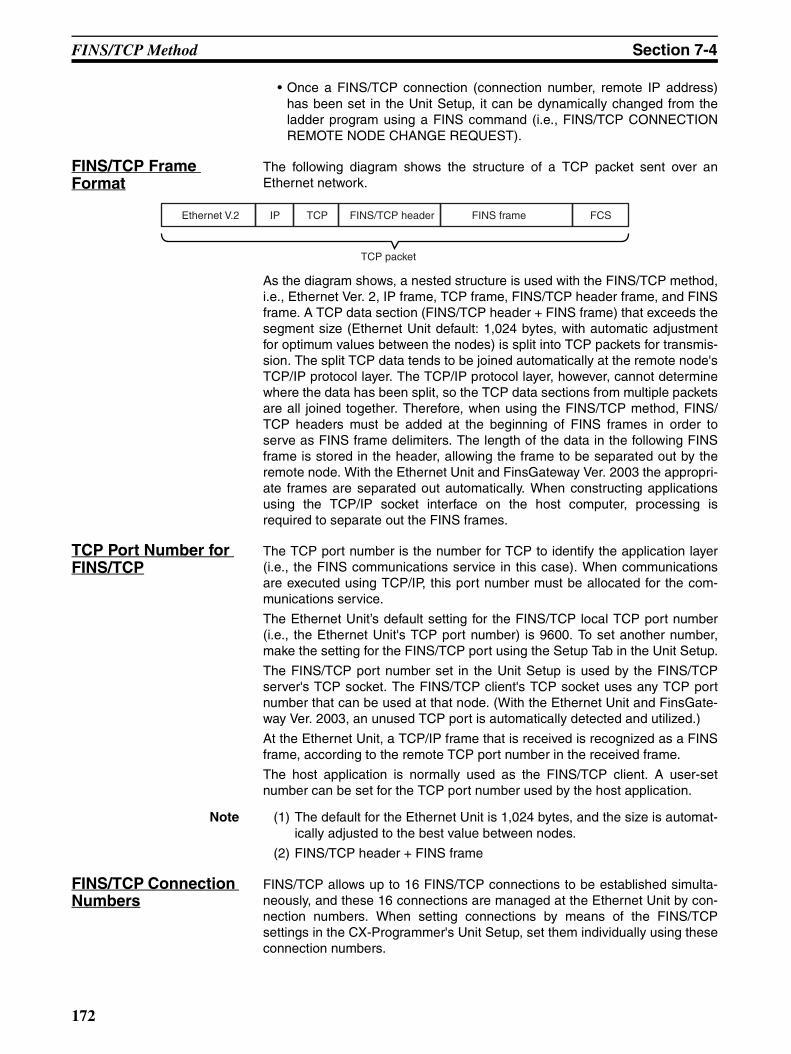
FINS/TCP Method Section 7-4
• Once a FINS/TCP connection (connection number, remote IP address)has been set in the Unit Setup, it can be dynamically changed from theladder program using a FINS command (i.e., FINS/TCP CONNECTIONREMOTE NODE CHANGE REQUEST).
FINS/TCP Frame Format
The following diagram shows the structure of a TCP packet sent over anEthernet network.
As the diagram shows, a nested structure is used with the FINS/TCP method,i.e., Ethernet Ver. 2, IP frame, TCP frame, FINS/TCP header frame, and FINSframe. A TCP data section (FINS/TCP header + FINS frame) that exceeds thesegment size (Ethernet Unit default: 1,024 bytes, with automatic adjustmentfor optimum values between the nodes) is split into TCP packets for transmis-sion. The split TCP data tends to be joined automatically at the remote node'sTCP/IP protocol layer. The TCP/IP protocol layer, however, cannot determinewhere the data has been split, so the TCP data sections from multiple packetsare all joined together. Therefore, when using the FINS/TCP method, FINS/TCP headers must be added at the beginning of FINS frames in order toserve as FINS frame delimiters. The length of the data in the following FINSframe is stored in the header, allowing the frame to be separated out by theremote node. With the Ethernet Unit and FinsGateway Ver. 2003 the appropri-ate frames are separated out automatically. When constructing applicationsusing the TCP/IP socket interface on the host computer, processing isrequired to separate out the FINS frames.
TCP Port Number for FINS/TCP
The TCP port number is the number for TCP to identify the application layer(i.e., the FINS communications service in this case). When communicationsare executed using TCP/IP, this port number must be allocated for the com-munications service.
The Ethernet Unit’s default setting for the FINS/TCP local TCP port number(i.e., the Ethernet Unit's TCP port number) is 9600. To set another number,make the setting for the FINS/TCP port using the Setup Tab in the Unit Setup.
The FINS/TCP port number set in the Unit Setup is used by the FINS/TCPserver's TCP socket. The FINS/TCP client's TCP socket uses any TCP portnumber that can be used at that node. (With the Ethernet Unit and FinsGate-way Ver. 2003, an unused TCP port is automatically detected and utilized.)
At the Ethernet Unit, a TCP/IP frame that is received is recognized as a FINSframe, according to the remote TCP port number in the received frame.
The host application is normally used as the FINS/TCP client. A user-setnumber can be set for the TCP port number used by the host application.
Note (1) The default for the Ethernet Unit is 1,024 bytes, and the size is automat-ically adjusted to the best value between nodes.
(2) FINS/TCP header + FINS frame
FINS/TCP Connection Numbers
FINS/TCP allows up to 16 FINS/TCP connections to be established simulta-neously, and these 16 connections are managed at the Ethernet Unit by con-nection numbers. When setting connections by means of the FINS/TCPsettings in the CX-Programmer's Unit Setup, set them individually using theseconnection numbers.
Ethernet V.2 IP TCP FINS frame FCSFINS/TCP header
TCP packet
172
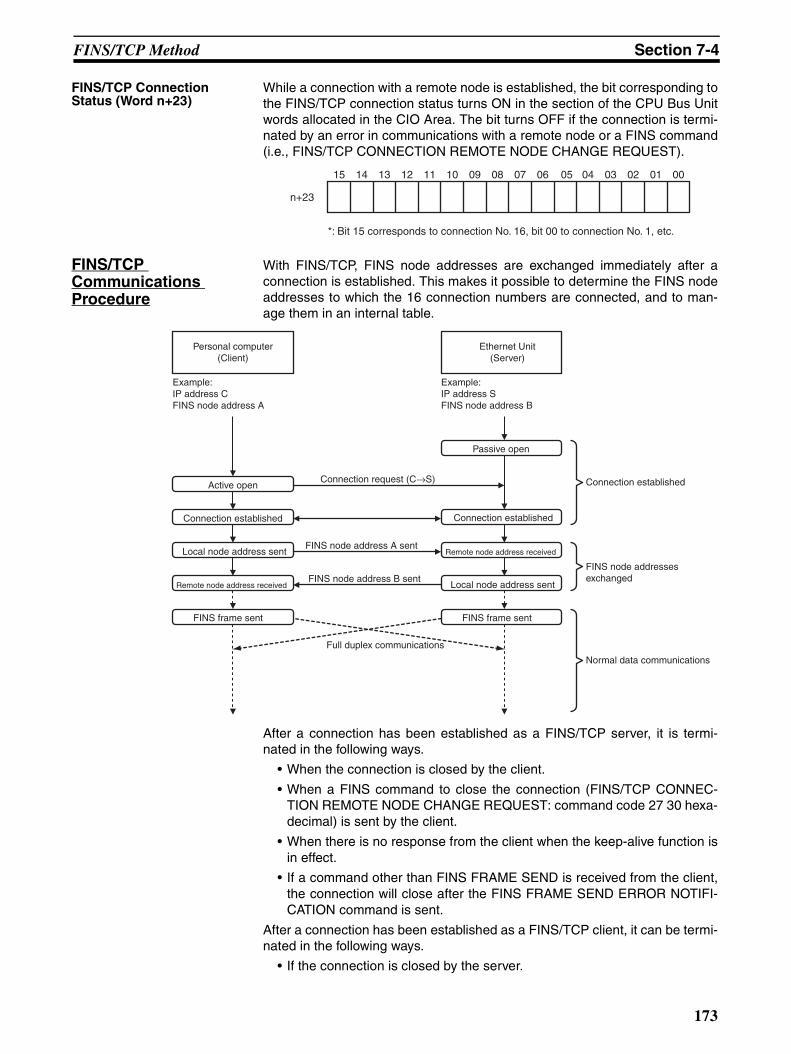
FINS/TCP Method Section 7-4
FINS/TCP Connection Status (Word n+23)
While a connection with a remote node is established, the bit corresponding tothe FINS/TCP connection status turns ON in the section of the CPU Bus Unitwords allocated in the CIO Area. The bit turns OFF if the connection is termi-nated by an error in communications with a remote node or a FINS command(i.e., FINS/TCP CONNECTION REMOTE NODE CHANGE REQUEST).
FINS/TCP Communications Procedure
With FINS/TCP, FINS node addresses are exchanged immediately after aconnection is established. This makes it possible to determine the FINS nodeaddresses to which the 16 connection numbers are connected, and to man-age them in an internal table.
After a connection has been established as a FINS/TCP server, it is termi-nated in the following ways.
• When the connection is closed by the client.
• When a FINS command to close the connection (FINS/TCP CONNEC-TION REMOTE NODE CHANGE REQUEST: command code 27 30 hexa-decimal) is sent by the client.
• When there is no response from the client when the keep-alive function isin effect.
• If a command other than FINS FRAME SEND is received from the client,the connection will close after the FINS FRAME SEND ERROR NOTIFI-CATION command is sent.
After a connection has been established as a FINS/TCP client, it can be termi-nated in the following ways.
• If the connection is closed by the server.
15 14 13 12 11 10 09 07 06 05 04 03 02 01 00
n+23
*: Bit 15 corresponds to connection No. 16, bit 00 to connection No. 1, etc.
08
Connection request (C→S)
FINS node address A sent
Ethernet Unit(Server)
Passive open
Connection established
Local node address sent
FINS frame sent
Personal computer(Client)
Active open
Local node address sent
Connection established
Remote node address receivedFINS node address B sent
FINS node addresses exchanged
Connection established
Normal data communications
Remote node address received
FINS frame sent
Full duplex communications
Example:IP address CFINS node address A
Example:IP address SFINS node address B
173
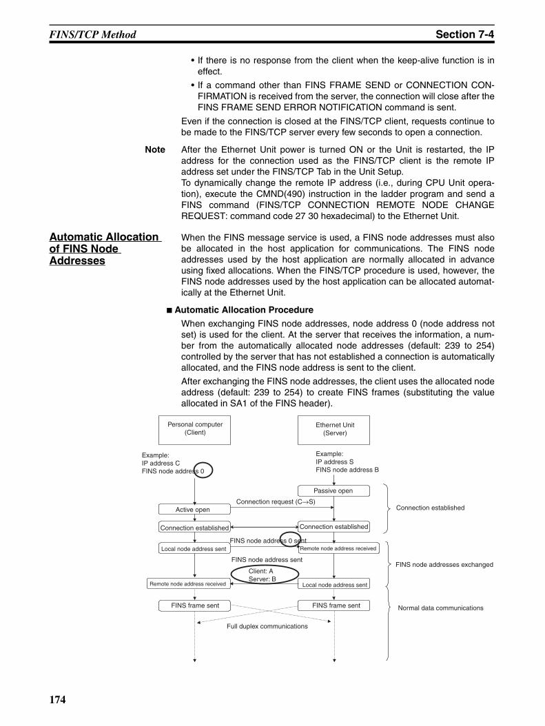
FINS/TCP Method Section 7-4
• If there is no response from the client when the keep-alive function is ineffect.
• If a command other than FINS FRAME SEND or CONNECTION CON-FIRMATION is received from the server, the connection will close after theFINS FRAME SEND ERROR NOTIFICATION command is sent.
Even if the connection is closed at the FINS/TCP client, requests continue tobe made to the FINS/TCP server every few seconds to open a connection.
Note After the Ethernet Unit power is turned ON or the Unit is restarted, the IPaddress for the connection used as the FINS/TCP client is the remote IPaddress set under the FINS/TCP Tab in the Unit Setup.To dynamically change the remote IP address (i.e., during CPU Unit opera-tion), execute the CMND(490) instruction in the ladder program and send aFINS command (FINS/TCP CONNECTION REMOTE NODE CHANGEREQUEST: command code 27 30 hexadecimal) to the Ethernet Unit.
Automatic Allocation of FINS Node Addresses
When the FINS message service is used, a FINS node addresses must alsobe allocated in the host application for communications. The FINS nodeaddresses used by the host application are normally allocated in advanceusing fixed allocations. When the FINS/TCP procedure is used, however, theFINS node addresses used by the host application can be allocated automat-ically at the Ethernet Unit.
Automatic Allocation Procedure
When exchanging FINS node addresses, node address 0 (node address notset) is used for the client. At the server that receives the information, a num-ber from the automatically allocated node addresses (default: 239 to 254)controlled by the server that has not established a connection is automaticallyallocated, and the FINS node address is sent to the client.
After exchanging the FINS node addresses, the client uses the allocated nodeaddress (default: 239 to 254) to create FINS frames (substituting the valueallocated in SA1 of the FINS header).
Personal computer(Client)
Ethernet Unit(Server)
Example:IP address CFINS node address 0
Example: IP address SFINS node address B
Passive open
Connection established
FINS node addresses exchanged
Normal data communications
Connection request (C→S)Active open
Connection established
Local node address sent
Remote node address received
FINS frame sent
Full duplex communications
FINS node address 0 sent
Connection established
Remote node address received
Local node address sent
FINS frame sent
FINS node address sent
Client: AServer: B
174
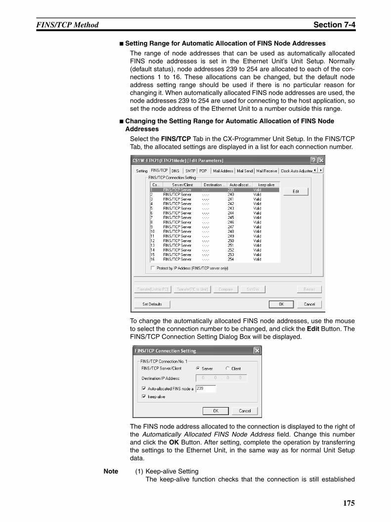
FINS/TCP Method Section 7-4
Setting Range for Automatic Allocation of FINS Node Addresses
The range of node addresses that can be used as automatically allocatedFINS node addresses is set in the Ethernet Unit’s Unit Setup. Normally(default status), node addresses 239 to 254 are allocated to each of the con-nections 1 to 16. These allocations can be changed, but the default nodeaddress setting range should be used if there is no particular reason forchanging it. When automatically allocated FINS node addresses are used, thenode addresses 239 to 254 are used for connecting to the host application, soset the node address of the Ethernet Unit to a number outside this range.
Changing the Setting Range for Automatic Allocation of FINS Node Addresses
Select the FINS/TCP Tab in the CX-Programmer Unit Setup. In the FINS/TCPTab, the allocated settings are displayed in a list for each connection number.
To change the automatically allocated FINS node addresses, use the mouseto select the connection number to be changed, and click the Edit Button. TheFINS/TCP Connection Setting Dialog Box will be displayed.
The FINS node address allocated to the connection is displayed to the right ofthe Automatically Allocated FINS Node Address field. Change this numberand click the OK Button. After setting, complete the operation by transferringthe settings to the Ethernet Unit, in the same way as for normal Unit Setupdata.
Note (1) Keep-alive SettingThe keep-alive function checks that the connection is still established
175
FINS/TCP Method Section 7-4
(alive) if communications do not occur for a set time period through acommunications line for which communications had been established.Even if the keep-alive function is not specified at the Ethernet Unit, a re-sponse is sent for checks sent from other nodes. If the power is turnedOFF to the host application (e.g., personal computer) while a connectionis established, the connection is no longer required, but will remain openuntil explicit close processing is performed. If the keep-alive option is se-lected, the connection is checked periodically, and close processing isperformed if a response is not received. For normal operations, select thekeep-alive option.
(2) Keep-alive Monitor Time SettingThe liveness checking interval (keep-alive) can be set from the CX-Pro-grammer in the TCP/IP keep-alive field of the Setup Tab in the Unit Setup.The default setting is 120 minutes, as defined in RFC, but setting the timerto several minutes is recommended when using FINS/TCP or other con-trol applications.
Procedure for Using FINS/TCP
Note Routing tables are required in the following situations:
• When communicating with a PLC or computer on another network (e.g.,remote programming or monitoring using FINS messages or a CX-Pro-grammer).
1. Make the basic settings.Refer to Section 2 Startup Procedure in the Operation Manual, Construction of Net-works.
↓2. Make the settings in the Unit Setup.
With the CX-Programmer connected online, select the Ethernet Unit in the CX-Program-mer's I/O Table Window. Right-click, and select Unit Setup. Then make the following set-tings in the Unit Setup Window.Setup Tab• FINS/TCP port (Default: 9600)• TCP/IP keep-alive (Default: 120 minutes)
FINS/TCP Tab• FINS/TCP server/client
Note: Set the server when connecting to host applications. • Remote IP addresses
Note: When connecting to host applications, set the IP address of the permitted client (personal computer or workstation) only when IP address protection is in effect. Do not set if protection is not required.
• Automatically allocated FINS node addresses• Keep-alive setting• IP addresses protection settingNote: When connecting to host applications, select this setting only when IP address protection is in effect.
↓3. Make the routing table settings and transfer them to each PLC. (See note.)
Set the routing tables with CX-Net, and transfer them to each PLC.
↓4. Create host applications using a programming language such as C language and the
personal computer’s (workstation’s) socket interface.
176
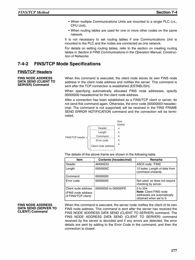
FINS/TCP Method Section 7-4
• When multiple Communications Units are mounted to a single PLC (i.e.,CPU Unit).
• When routing tables are used for one or more other nodes on the samenetwork.
It is not necessary to set routing tables if one Communications Unit ismounted to the PLC and the nodes are connected as one network.
For details on setting routing tables, refer to the section on creating routingtables in Section 6 FINS Communications in the Operation Manual, Construc-tion of Networks.
7-4-2 FINS/TCP Mode Specifications
FINS/TCP Headers
FINS NODE ADDRESS DATA SEND (CLIENT TO SERVER) Command
When this command is executed, the client node stores its own FINS nodeaddress in the client node address and notifies the server. This command issent after the TCP connection is established (ESTABLISH).
When specifying automatically allocated FINS node addresses, specify00000000 hexadecimal for the client node address.
After a connection has been established as a FINS/TCP client or server, donot send this command again. Otherwise, the error code (00000003 hexadec-imal: The command is not supported) will be received in the FINS FRAMESEND ERROR NOTIFICATION command and the connection will be termi-nated.
The details of the above frame are shown in the following table.
FINS NODE ADDRESS DATA SEND (SERVER TO CLIENT) Command
When this command is executed, the server node notifies the client of its ownFINS node address. This command is sent after the server has received theFINS NODE ADDRESS DATA SEND (CLIENT TO SERVER) command. TheFINS NODE ADDRESS DATA SEND (CLIENT TO SERVER) commandreceived by the server is decoded and if any errors are detected, the errordetails are sent by adding to the Error Code in the command, and then theconnection is closed.
Item Contents (hexadecimal) Remarks
Header 46494E53 ASCII code: ‘FINS’
Length 0000000C 12 bytes: Length of data from command onwards.
Command 00000000
Error code 00000000 Not used, so does not require checking by server.
Client node address(FINS node address of FINS/TCP client)
00000000 to 000000FE 0 to 254Note: Client FINS node addresses are automatically obtained when set to 0.
Size (bytes)
FINS/TCP header
Header
Length
Command
Error code
Client node address
4
4
4
4
4
177
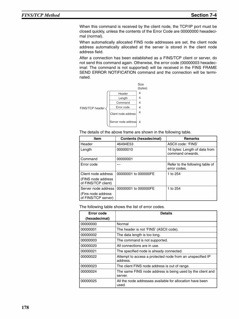
FINS/TCP Method Section 7-4
When this command is received by the client node, the TCP/IP port must beclosed quickly, unless the contents of the Error Code are 00000000 hexadeci-mal (normal).
When automatically allocated FINS node addresses are set, the client nodeaddress automatically allocated at the server is stored in the client nodeaddress field.
After a connection has been established as a FINS/TCP client or server, donot send this command again. Otherwise, the error code (00000003 hexadec-imal: The command is not supported) will be received in the FINS FRAMESEND ERROR NOTIFICATION command and the connection will be termi-nated.
The details of the above frame are shown in the following table.
The following table shows the list of error codes.
Item Contents (hexadecimal) Remarks
Header 46494E53 ASCII code: ‘FINS’
Length 00000010 16 bytes: Length of data from command onwards.
Command 00000001
Error code --- Refer to the following table of error codes.
Client node address
(FINS node address of FINS/TCP client)
00000001 to 000000FE 1 to 254
Server node address
(Fins node address of FINS/TCP server)
00000001 to 000000FE 1 to 254
Error code(hexadecimal)
Details
00000000 Normal
00000001 The header is not ‘FINS’ (ASCII code).
00000002 The data length is too long.
00000003 The command is not supported.
00000020 All connections are in use.
00000021 The specified node is already connected.
00000022 Attempt to access a protected node from an unspecified IP address.
00000023 The client FINS node address is out of range.
00000024 The same FINS node address is being used by the client and server.
00000025 All the node addresses available for allocation have been used.
Header
Length
Command
Error code
Server node address
Size (bytes)
FINS/TCP header
4
4
4
4
4
4
Client node address
178
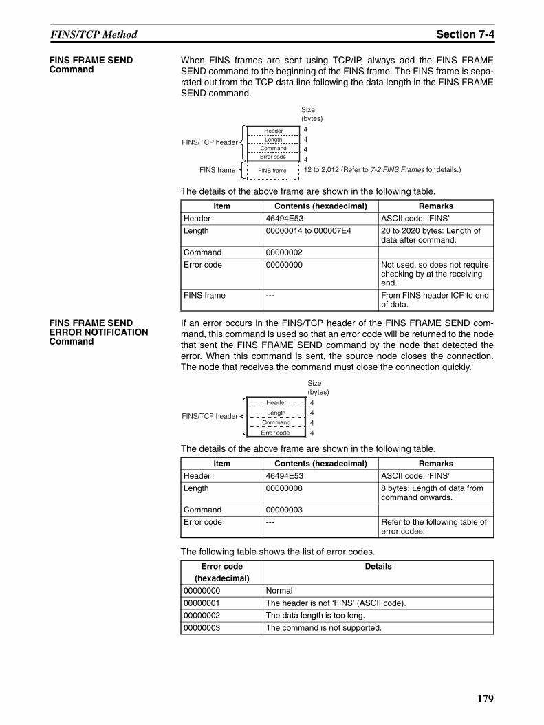
FINS/TCP Method Section 7-4
FINS FRAME SEND Command
When FINS frames are sent using TCP/IP, always add the FINS FRAMESEND command to the beginning of the FINS frame. The FINS frame is sepa-rated out from the TCP data line following the data length in the FINS FRAMESEND command.
The details of the above frame are shown in the following table.
FINS FRAME SEND ERROR NOTIFICATION Command
If an error occurs in the FINS/TCP header of the FINS FRAME SEND com-mand, this command is used so that an error code will be returned to the nodethat sent the FINS FRAME SEND command by the node that detected theerror. When this command is sent, the source node closes the connection.The node that receives the command must close the connection quickly.
The details of the above frame are shown in the following table.
The following table shows the list of error codes.
Item Contents (hexadecimal) Remarks
Header 46494E53 ASCII code: ‘FINS’
Length 00000014 to 000007E4 20 to 2020 bytes: Length of data after command.
Command 00000002
Error code 00000000 Not used, so does not require checking by at the receiving end.
FINS frame --- From FINS header ICF to end of data.
Size (bytes)
444412 to 2,012 (Refer to 7-2 FINS Frames for details.)
Header
Length
Command
Error code
FINS frame
FINS/TCP header
FINS frame
Item Contents (hexadecimal) Remarks
Header 46494E53 ASCII code: ‘FINS’
Length 00000008 8 bytes: Length of data from command onwards.
Command 00000003
Error code --- Refer to the following table of error codes.
Error code(hexadecimal)
Details
00000000 Normal
00000001 The header is not ‘FINS’ (ASCII code).
00000002 The data length is too long.
00000003 The command is not supported.
Size (bytes)
4444
FINS/TCP header
Header
Length
Command
Error code
179
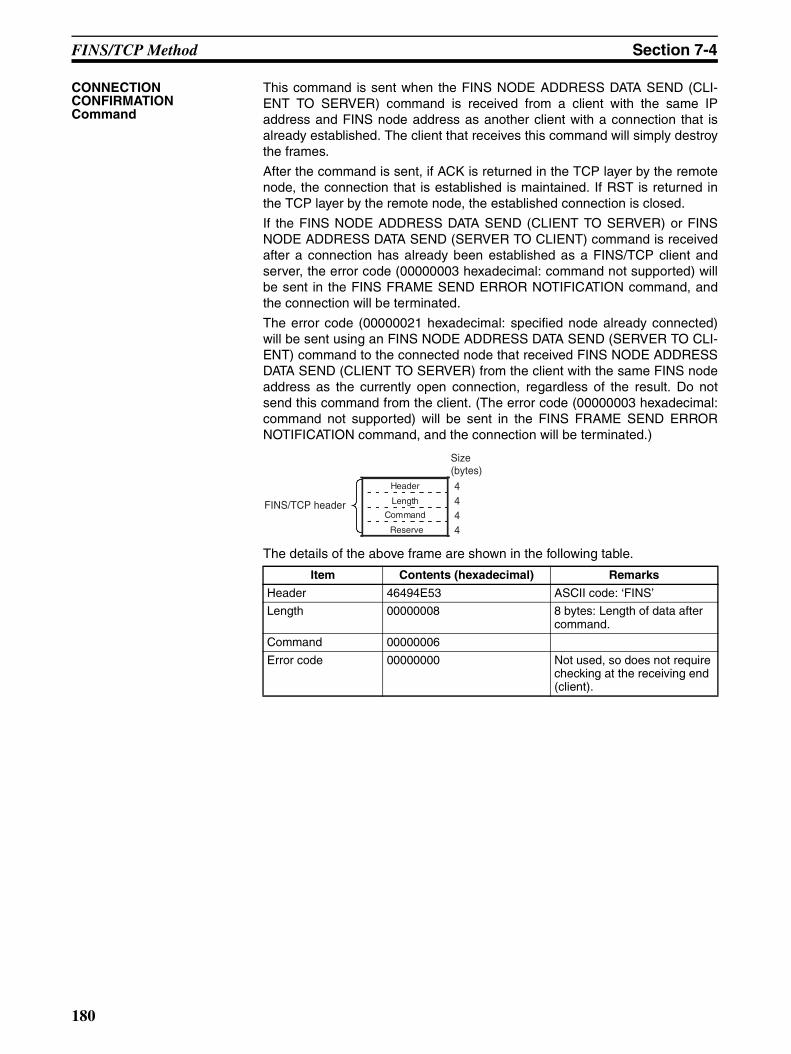
FINS/TCP Method Section 7-4
CONNECTION CONFIRMATION Command
This command is sent when the FINS NODE ADDRESS DATA SEND (CLI-ENT TO SERVER) command is received from a client with the same IPaddress and FINS node address as another client with a connection that isalready established. The client that receives this command will simply destroythe frames.
After the command is sent, if ACK is returned in the TCP layer by the remotenode, the connection that is established is maintained. If RST is returned inthe TCP layer by the remote node, the established connection is closed.
If the FINS NODE ADDRESS DATA SEND (CLIENT TO SERVER) or FINSNODE ADDRESS DATA SEND (SERVER TO CLIENT) command is receivedafter a connection has already been established as a FINS/TCP client andserver, the error code (00000003 hexadecimal: command not supported) willbe sent in the FINS FRAME SEND ERROR NOTIFICATION command, andthe connection will be terminated.
The error code (00000021 hexadecimal: specified node already connected)will be sent using an FINS NODE ADDRESS DATA SEND (SERVER TO CLI-ENT) command to the connected node that received FINS NODE ADDRESSDATA SEND (CLIENT TO SERVER) from the client with the same FINS nodeaddress as the currently open connection, regardless of the result. Do notsend this command from the client. (The error code (00000003 hexadecimal:command not supported) will be sent in the FINS FRAME SEND ERRORNOTIFICATION command, and the connection will be terminated.)
The details of the above frame are shown in the following table.
Item Contents (hexadecimal) Remarks
Header 46494E53 ASCII code: ‘FINS’
Length 00000008 8 bytes: Length of data after command.
Command 00000006
Error code 00000000 Not used, so does not require checking at the receiving end (client).
Size (bytes)
4444
FINS/TCP header
Header
Length
Command
Reserve
180
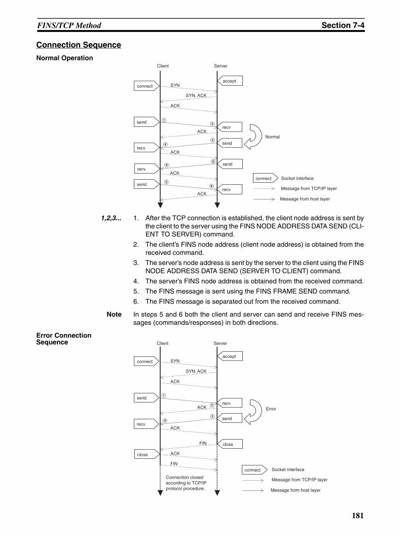
FINS/TCP Method Section 7-4
Connection Sequence
Normal Operation
1,2,3... 1. After the TCP connection is established, the client node address is sent bythe client to the server using the FINS NODE ADDRESS DATA SEND (CLI-ENT TO SERVER) command.
2. The client’s FINS node address (client node address) is obtained from thereceived command.
3. The server’s node address is sent by the server to the client using the FINSNODE ADDRESS DATA SEND (SERVER TO CLIENT) command.
4. The server’s FINS node address is obtained from the received command.
5. The FINS message is sent using the FINS FRAME SEND command.
6. The FINS message is separated out from the received command.
Note In steps 5 and 6 both the client and server can send and receive FINS mes-sages (commands/responses) in both directions.
Error Connection Sequence
connect
connect
send
recv
accept
recv
send
SYN
SYN, ACK
ACK
ACK
ACK
recvsend
sendrecv
ACK
ACK
Client Server
Normal
Socket interface
Message from TCP/IP layer
Message from host layer
AB
CD
EF
EF
Client Server
Error
Socket interface
Message from TCP/IP layer
Message from host layer
A
B
CD
SYN
SYN, ACK
ACK
ACK
ACK
FIN
FIN
ACK
connect
connect
send
recv
close
accept
recv
send
close
Connection closed according to TCP/IP protocol procedure.
181
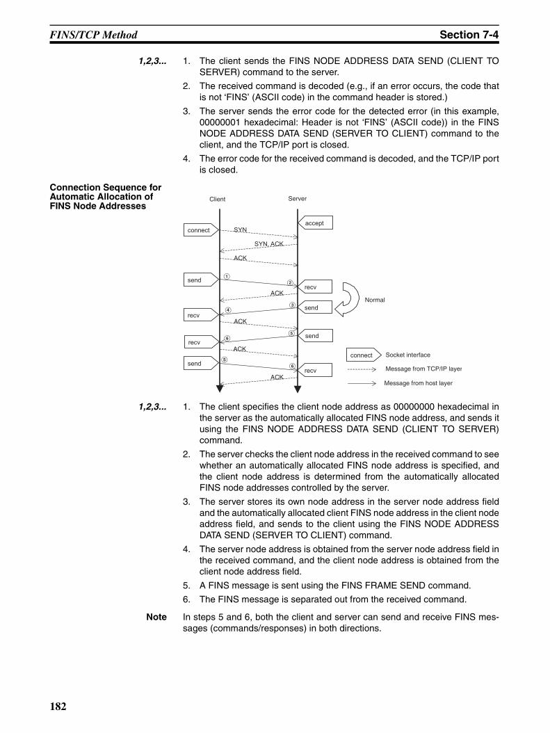
FINS/TCP Method Section 7-4
1,2,3... 1. The client sends the FINS NODE ADDRESS DATA SEND (CLIENT TOSERVER) command to the server.
2. The received command is decoded (e.g., if an error occurs, the code thatis not ‘FINS’ (ASCII code) in the command header is stored.)
3. The server sends the error code for the detected error (in this example,00000001 hexadecimal: Header is not ‘FINS’ (ASCII code)) in the FINSNODE ADDRESS DATA SEND (SERVER TO CLIENT) command to theclient, and the TCP/IP port is closed.
4. The error code for the received command is decoded, and the TCP/IP portis closed.
Connection Sequence for Automatic Allocation of FINS Node Addresses
1,2,3... 1. The client specifies the client node address as 00000000 hexadecimal inthe server as the automatically allocated FINS node address, and sends itusing the FINS NODE ADDRESS DATA SEND (CLIENT TO SERVER)command.
2. The server checks the client node address in the received command to seewhether an automatically allocated FINS node address is specified, andthe client node address is determined from the automatically allocatedFINS node addresses controlled by the server.
3. The server stores its own node address in the server node address fieldand the automatically allocated client FINS node address in the client nodeaddress field, and sends to the client using the FINS NODE ADDRESSDATA SEND (SERVER TO CLIENT) command.
4. The server node address is obtained from the server node address field inthe received command, and the client node address is obtained from theclient node address field.
5. A FINS message is sent using the FINS FRAME SEND command.
6. The FINS message is separated out from the received command.
Note In steps 5 and 6, both the client and server can send and receive FINS mes-sages (commands/responses) in both directions.
connect
send
recv
accept
recv
send
SYN
SYN, ACK
ACK
ACK
ACK
connect
recvsend
sendrecv
ACK
ACK
Client Server
Socket interface
Message from TCP/IP layer
Message from host layer
Normal
AB
CD
EF
FE
182
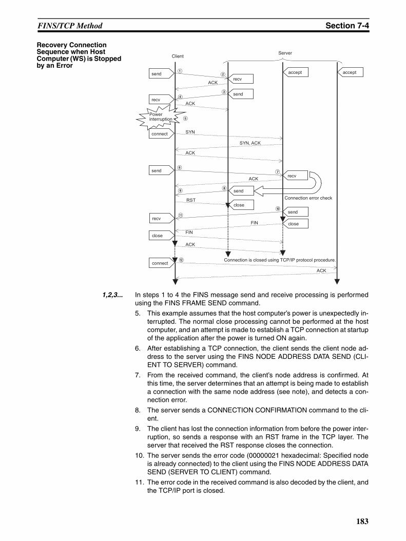
FINS/TCP Method Section 7-4
Recovery Connection Sequence when Host Computer (WS) is Stopped by an Error
1,2,3... In steps 1 to 4 the FINS message send and receive processing is performedusing the FINS FRAME SEND command.
5. This example assumes that the host computer’s power is unexpectedly in-terrupted. The normal close processing cannot be performed at the hostcomputer, and an attempt is made to establish a TCP connection at startupof the application after the power is turned ON again.
6. After establishing a TCP connection, the client sends the client node ad-dress to the server using the FINS NODE ADDRESS DATA SEND (CLI-ENT TO SERVER) command.
7. From the received command, the client’s node address is confirmed. Atthis time, the server determines that an attempt is being made to establisha connection with the same node address (see note), and detects a con-nection error.
8. The server sends a CONNECTION CONFIRMATION command to the cli-ent.
9. The client has lost the connection information from before the power inter-ruption, so sends a response with an RST frame in the TCP layer. Theserver that received the RST response closes the connection.
10. The server sends the error code (00000021 hexadecimal: Specified nodeis already connected) to the client using the FINS NODE ADDRESS DATASEND (SERVER TO CLIENT) command.
11. The error code in the received command is also decoded by the client, andthe TCP/IP port is closed.
recv
send
send
recv
recv
send
ACK
ACK
connect
sendrecv
send
SYN
SYN, ACK
ACK
ACK
accept
RST
FIN
FIN
ACK
close
close
close
Connection error check
accept
connect
ACK
ClientServer
Power interruption
Connection is closed using TCP/IP protocol procedure.
AB
CD
E
FG
HI
J
K
L
183
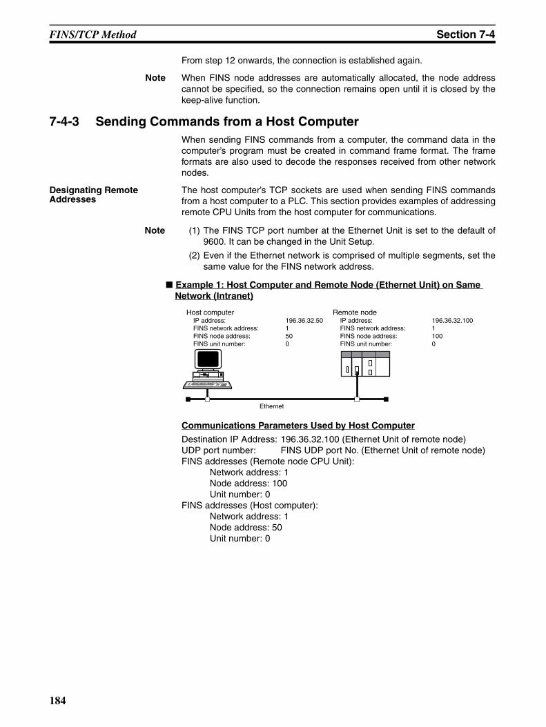
FINS/TCP Method Section 7-4
From step 12 onwards, the connection is established again.
Note When FINS node addresses are automatically allocated, the node addresscannot be specified, so the connection remains open until it is closed by thekeep-alive function.
7-4-3 Sending Commands from a Host ComputerWhen sending FINS commands from a computer, the command data in thecomputer’s program must be created in command frame format. The frameformats are also used to decode the responses received from other networknodes.
Designating Remote Addresses
The host computer’s TCP sockets are used when sending FINS commandsfrom a host computer to a PLC. This section provides examples of addressingremote CPU Units from the host computer for communications.
Note (1) The FINS TCP port number at the Ethernet Unit is set to the default of9600. It can be changed in the Unit Setup.
(2) Even if the Ethernet network is comprised of multiple segments, set thesame value for the FINS network address.
Example 1: Host Computer and Remote Node (Ethernet Unit) on Same Network (Intranet)
Communications Parameters Used by Host Computer
Destination IP Address: 196.36.32.100 (Ethernet Unit of remote node)UDP port number: FINS UDP port No. (Ethernet Unit of remote node)FINS addresses (Remote node CPU Unit):
Network address: 1Node address: 100Unit number: 0
FINS addresses (Host computer):Network address: 1Node address: 50Unit number: 0
Host computerIP address: 196.36.32.50FINS network address: 1FINS node address: 50FINS unit number: 0
Remote nodeIP address: 196.36.32.100FINS network address: 1FINS node address: 100FINS unit number: 0
Ethernet
184
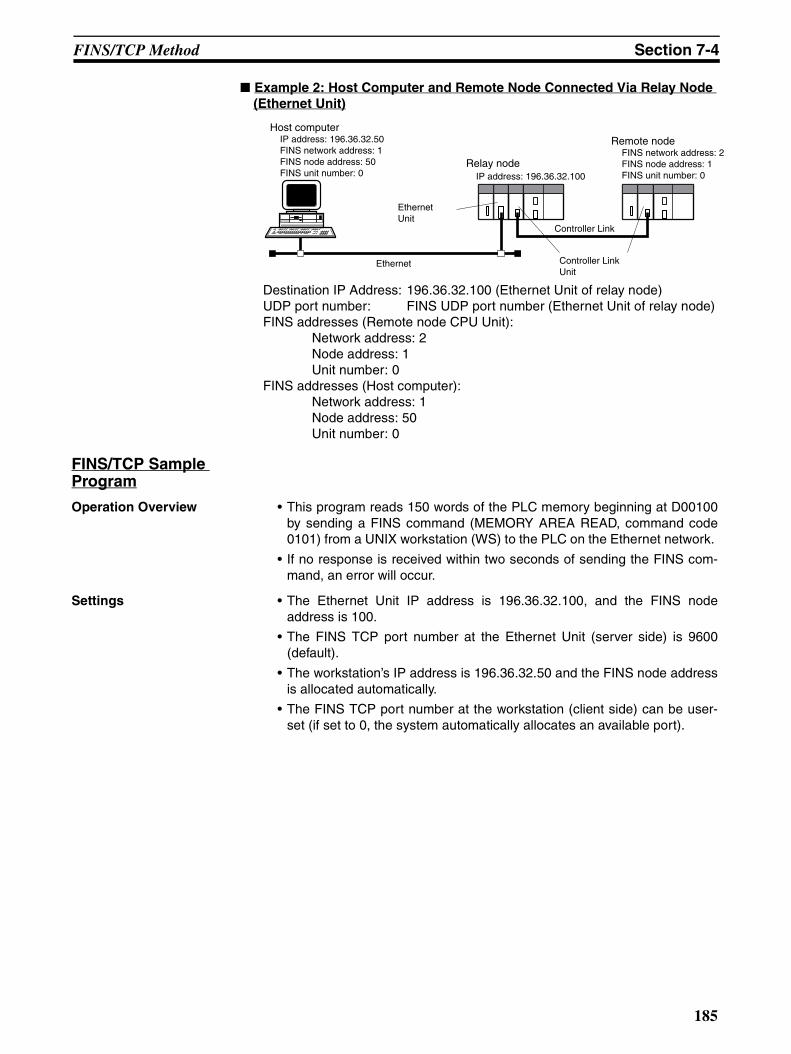
FINS/TCP Method Section 7-4
Example 2: Host Computer and Remote Node Connected Via Relay Node (Ethernet Unit)
Destination IP Address: 196.36.32.100 (Ethernet Unit of relay node)UDP port number: FINS UDP port number (Ethernet Unit of relay node)FINS addresses (Remote node CPU Unit):
Network address: 2Node address: 1Unit number: 0
FINS addresses (Host computer):Network address: 1Node address: 50Unit number: 0
FINS/TCP Sample Program
Operation Overview • This program reads 150 words of the PLC memory beginning at D00100by sending a FINS command (MEMORY AREA READ, command code0101) from a UNIX workstation (WS) to the PLC on the Ethernet network.
• If no response is received within two seconds of sending the FINS com-mand, an error will occur.
Settings • The Ethernet Unit IP address is 196.36.32.100, and the FINS nodeaddress is 100.
• The FINS TCP port number at the Ethernet Unit (server side) is 9600(default).
• The workstation’s IP address is 196.36.32.50 and the FINS node addressis allocated automatically.
• The FINS TCP port number at the workstation (client side) can be user-set (if set to 0, the system automatically allocates an available port).
Host computerIP address: 196.36.32.50FINS network address: 1FINS node address: 50FINS unit number: 0
Relay nodeIP address: 196.36.32.100
Ethernet
Remote nodeFINS network address: 2FINS node address: 1FINS unit number: 0
Controller Link
EthernetUnit
Controller LinkUnit
185
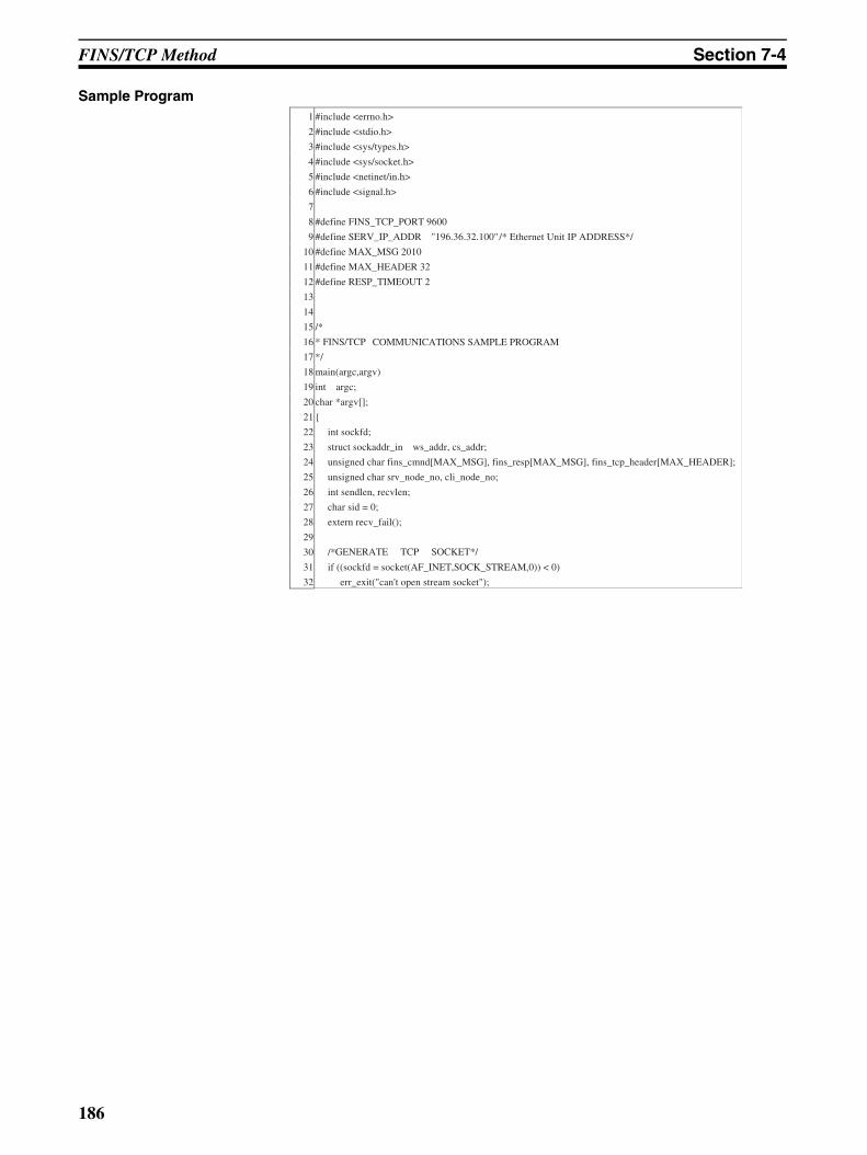
FINS/TCP Method Section 7-4
Sample Program
/* Ethernet Unit IP ADDRESS*/
COMMUNICATIONS SAMPLE PROGRAM
GENERATE TCP SOCKET*/
1 #include <errno.h>
2 #include <stdio.h>
3 #include <sys/types.h>
4 #include <sys/socket.h>
5 #include <netinet/in.h>
6 #include <signal.h>
7
8 #define FINS_TCP_PORT 9600
9 #define SERV_IP_ADDR "196.36.32.100"
10 #define MAX_MSG 2010
11 #define MAX_HEADER 32
12 #define RESP_TIMEOUT 2
13
14
15 /*
16 * FINS/TCP
17 */
18 main(argc,argv)
19 int argc;
20 char *argv[];
21
22 int sockfd;
23 struct sockaddr_in ws_addr, cs_addr;
24 unsigned char fins_cmnd[MAX_MSG], fins_resp[MAX_MSG], fins_tcp_header[MAX_HEADER];
25 unsigned char srv_node_no, cli_node_no;
26 int sendlen, recvlen;
27 char sid = 0;
28 extern recv_fail();
29
30 /*
31 if ((sockfd = socket(AF_INET,SOCK_STREAM,0)) < 0)
32 err_exit("can't open stream socket");
186
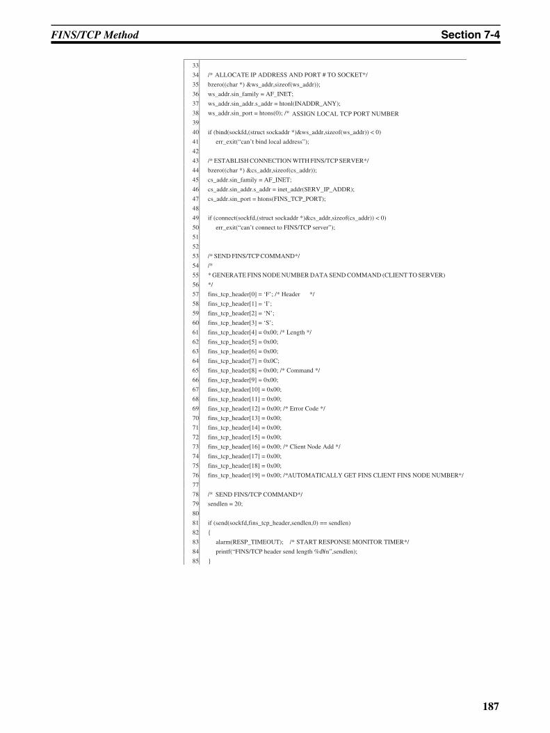
FINS/TCP Method Section 7-4
33
34 /*
35 bzero((char *) &ws_addr,sizeof(ws_addr));
36 ws_addr.sin_family = AF_INET;
37 ws_addr.sin_addr.s_addr = htonl(INADDR_ANY);
38 ws_addr.sin_port = htons(0); /*
39
40 if (bind(sockfd,(struct sockaddr *)&ws_addr,sizeof(ws_addr)) < 0)
41 err_exit(“can’t bind local address”);
42
43 /* ESTABLISH CONNECTION WITH FINS/TCP SERVER*/
44 bzero((char *) &cs_addr,sizeof(cs_addr));
45 cs_addr.sin_family = AF_INET;
46 cs_addr.sin_addr.s_addr = inet_addr(SERV_IP_ADDR);
47 cs_addr.sin_port = htons(FINS_TCP_PORT);
48
49 if (connect(sockfd,(struct sockaddr *)&cs_addr,sizeof(cs_addr)) < 0)
50 err_exit(“can’t connect to FINS/TCP server”);
51
52
53 /* SEND FINS/TCP COMMAND*/
54 /*
55 * GENERATE FINS NODE NUMBER DATA SEND COMMAND (CLIENT TO SERVER)
56 */
57 fins_tcp_header[0] = ‘F’; /* Header */
58 fins_tcp_header[1] = ‘I’;
59 fins_tcp_header[2] = ‘N’;
60 fins_tcp_header[3] = ‘S’;
61 fins_tcp_header[4] = 0x00; /* Length */
62 fins_tcp_header[5] = 0x00;
63 fins_tcp_header[6] = 0x00;
64 fins_tcp_header[7] = 0x0C;
65 fins_tcp_header[8] = 0x00; /* Command */
66 fins_tcp_header[9] = 0x00;
67 fins_tcp_header[10] = 0x00;
68 fins_tcp_header[11] = 0x00;
69 fins_tcp_header[12] = 0x00; /* Error Code */
70 fins_tcp_header[13] = 0x00;
71 fins_tcp_header[14] = 0x00;
72 fins_tcp_header[15] = 0x00;
73 fins_tcp_header[16] = 0x00; /* Client Node Add */
74 fins_tcp_header[17] = 0x00;
75 fins_tcp_header[18] = 0x00;
76 fins_tcp_header[19] = 0x00; /*
77
78 /*
79 sendlen = 20;
80
81 if (send(sockfd,fins_tcp_header,sendlen,0) == sendlen)
82
83 alarm(RESP_TIMEOUT); /*
84 printf(“FINS/TCP header send length %d¥n”,sendlen);
85
ALLOCATE IP ADDRESS AND PORT # TO SOCKET*/
ASSIGN LOCAL TCP PORT NUMBER
AUTOMATICALLY GET FINS CLIENT FINS NODE NUMBER*/
START RESPONSE MONITOR TIMER*/
SEND FINS/TCP COMMAND*/
187
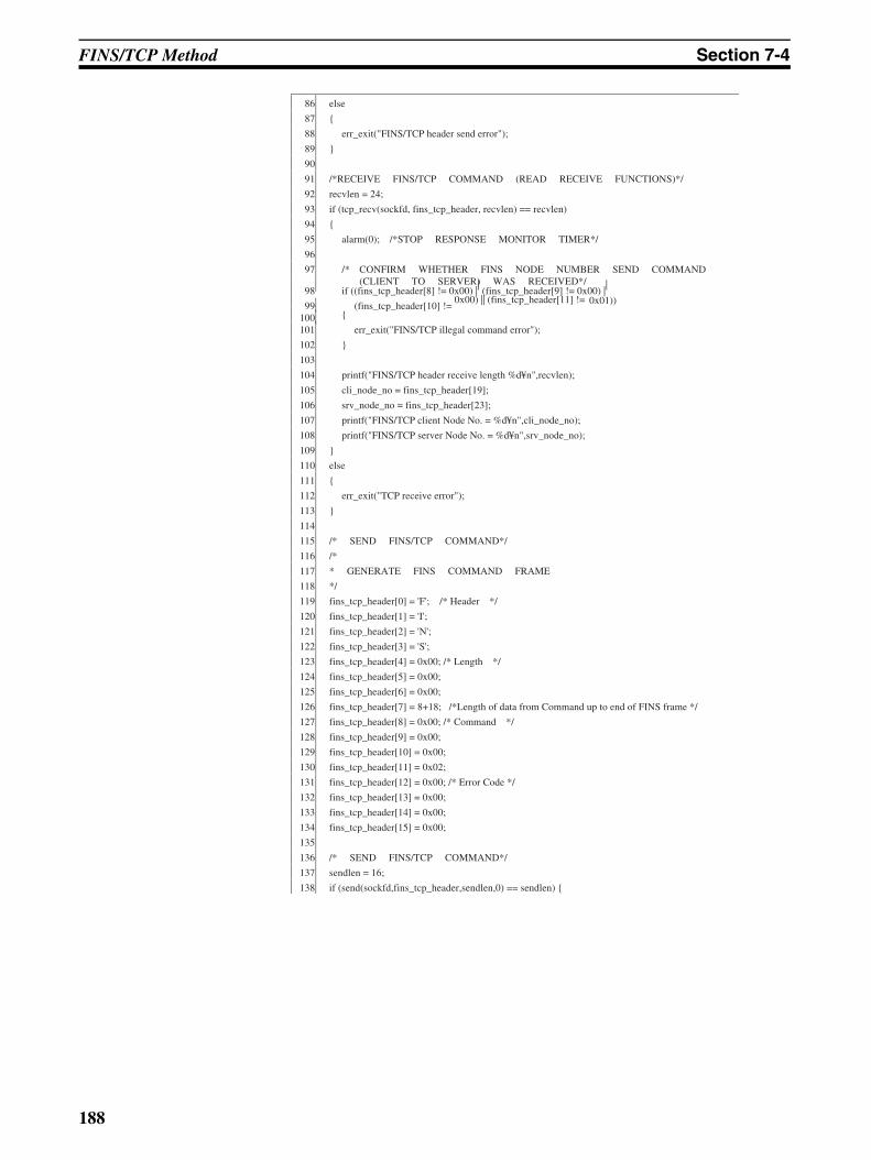
FINS/TCP Method Section 7-4
86 else
87
88 err_exit("FINS/TCP header send error");
89
90
91 /*RECEIVE FINS/TCP COMMAND (READ RECEIVE FUNCTIONS)*/
92 recvlen = 24;
93 if (tcp_recv(sockfd, fins_tcp_header, recvlen) == recvlen)
94
95 alarm(0); /*STOP RESPONSE MONITOR TIMER*/
96
97 /* CONFIRM WHETHER FINS NODE NUMBER SEND COMMAND (CLIENT TO SERVER) WAS RECEIVED*/
98
if ((fins_tcp_header[8] != 0x00) || (fins_tcp_header[9] != 0x00) |
|
99
(fins_tcp_header[10] != 0x00) || (fins_tcp_header[11] != 0x01))
100
101 err_exit("FINS/TCP illegal command error");
102
103
104 printf("FINS/TCP header receive length %d¥n",recvlen);
105 cli_node_no = fins_tcp_header[19];
106 srv_node_no = fins_tcp_header[23];
107 printf("FINS/TCP client Node No. = %d¥n",cli_node_no);
108 printf("FINS/TCP server Node No. = %d¥n",srv_node_no);
109
110 else
111
112 err_exit("TCP receive error");
113
114
115 /* SEND FINS/TCP COMMAND*/
116 /*
117 * GENERATE FINS COMMAND FRAME
118 */
119 fins_tcp_header[0] = 'F'; /* Header */
120 fins_tcp_header[1] = 'I';
121 fins_tcp_header[2] = 'N';
122 fins_tcp_header[3] = 'S';
123 fins_tcp_header[4] = 0x00; /* Length */
124 fins_tcp_header[5] = 0x00;
125 fins_tcp_header[6] = 0x00;
126 fins_tcp_header[7] = 8+18; /*Length of data from Command up to end of FINS frame */
127 fins_tcp_header[8] = 0x00; /* Command */
128 fins_tcp_header[9] = 0x00;
129 fins_tcp_header[10] = 0x00;
130 fins_tcp_header[11] = 0x02;
131 fins_tcp_header[12] = 0x00; /* Error Code */
132 fins_tcp_header[13] = 0x00;
133 fins_tcp_header[14] = 0x00;
134 fins_tcp_header[15] = 0x00;
135
136 /* SEND FINS/TCP COMMAND*/
137 sendlen = 16;
138 if (send(sockfd,fins_tcp_header,sendlen,0) == sendlen)
188
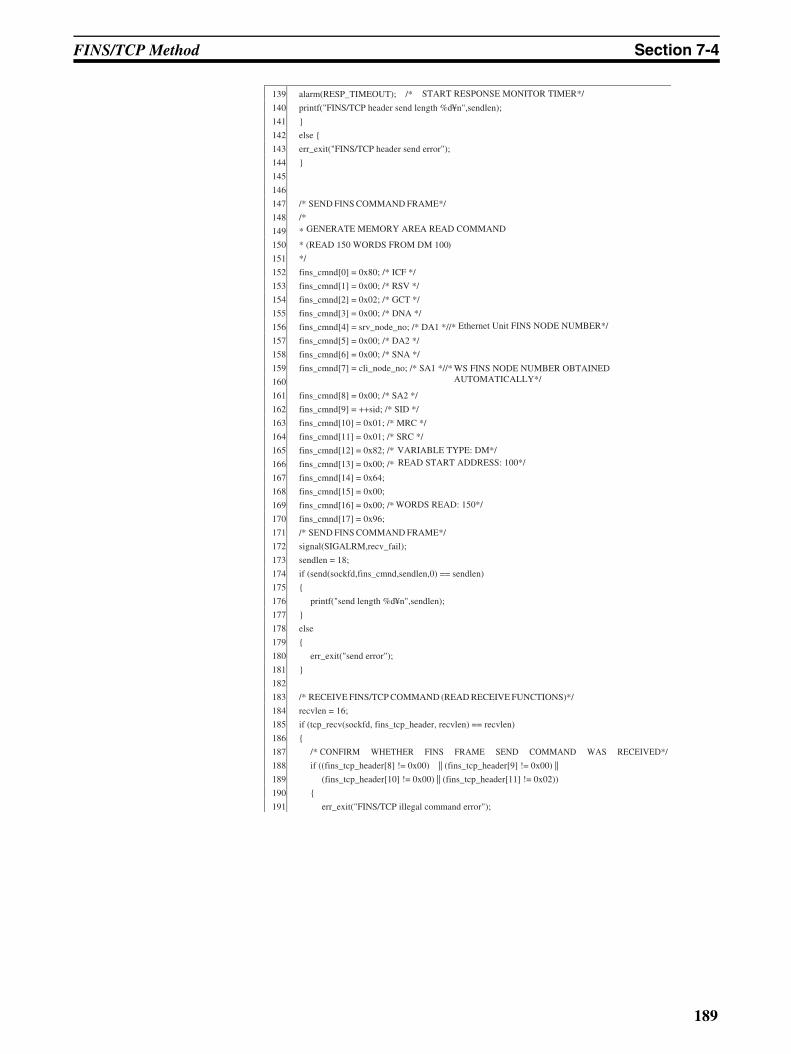
FINS/TCP Method Section 7-4
139 alarm(RESP_TIMEOUT); /*
140 printf("FINS/TCP header send length %d¥n",sendlen);
141
142 else
143 err_exit("FINS/TCP header send error");
144
145
146
147 /* SEND FINS COMMAND FRAME*/
148 /*
149 *
150 * (READ 150 WORDS FROM DM 100)
151 */
152 fins_cmnd[0] = 0x80; /* ICF */
153 fins_cmnd[1] = 0x00; /* RSV */
154 fins_cmnd[2] = 0x02; /* GCT */
155 fins_cmnd[3] = 0x00; /* DNA */
156 fins_cmnd[4] = srv_node_no; /* DA1 *//*
157 fins_cmnd[5] = 0x00; /* DA2 */
158 fins_cmnd[6] = 0x00; /* SNA */
159 fins_cmnd[7] = cli_node_no; /* SA1 *//*
160
161 fins_cmnd[8] = 0x00; /* SA2 */
162 fins_cmnd[9] = ++sid; /* SID */
163 fins_cmnd[10] = 0x01; /* MRC */
164 fins_cmnd[11] = 0x01; /* SRC */
165 fins_cmnd[12] = 0x82; /*
166 fins_cmnd[13] = 0x00; /*
167 fins_cmnd[14] = 0x64;
168 fins_cmnd[15] = 0x00;
169 fins_cmnd[16] = 0x00; /*
170 fins_cmnd[17] = 0x96;
171 /* SEND FINS COMMAND FRAME*/
172 signal(SIGALRM,recv_fail);
173 sendlen = 18;
174 if (send(sockfd,fins_cmnd,sendlen,0) == sendlen)
175
176 printf("send length %d¥n",sendlen);
177
178 else
179
180 err_exit("send error");
181
182
183 /* RECEIVE FINS/TCP COMMAND (READ RECEIVE FUNCTIONS)*/
184 recvlen = 16;
185 if (tcp_recv(sockfd, fins_tcp_header, recvlen) == recvlen)
186
187 /* CONFIRM WHETHER FINS FRAME SEND COMMAND WAS RECEIVED*/
188 if ((fins_tcp_header[8] != 0x00) || (fins_tcp_header[9] != 0x00) ||
189 (fins_tcp_header[10] != 0x00) || (fins_tcp_header[11] != 0x02))
190
191 err_exit("FINS/TCP illegal command error");
GENERATE MEMORY AREA READ COMMAND
Ethernet Unit FINS NODE NUMBER*/
WS FINS NODE NUMBER OBTAINED AUTOMATICALLY*/
VARIABLE TYPE: DM*/READ START ADDRESS: 100*/
WORDS READ: 150*/
START RESPONSE MONITOR TIMER*/
189
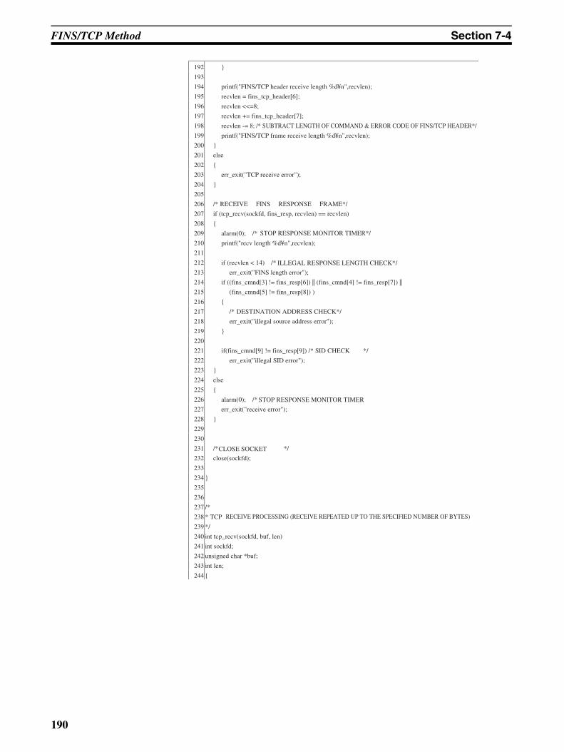
FINS/TCP Method Section 7-4
192
193
194 printf("FINS/TCP header receive length %d¥n",recvlen);
195 recvlen = fins_tcp_header[6];
196 recvlen <<=8;
197 recvlen += fins_tcp_header[7];
198 recvlen -= 8; /* SUBTRACT LENGTH OF COMMAND & ERROR CODE OF FINS/TCP HEADER*/
199 printf("FINS/TCP frame receive length %d¥n",recvlen);
200
201 else
202
203 err_exit("TCP receive error");
204
205
206 /* RECEIVE FINS RESPONSE FRAME*/
207 if (tcp_recv(sockfd, fins_resp, recvlen) == recvlen)
208
209 alarm(0); /*
210 printf("recv length %d¥n",recvlen);
211
212 if (recvlen < 14) /*
213 err_exit("FINS length error");
214 if ((fins_cmnd[3] != fins_resp[6]) || (fins_cmnd[4] != fins_resp[7]) ||
215 (fins_cmnd[5] != fins_resp[8]) )
216
217 /*
218 err_exit("illegal source address error");
219
220
221 if(fins_cmnd[9] != fins_resp[9]) /* SID CHECK */
222 err_exit("illegal SID error");
223
224 else
225
226 alarm(0); /*
227 err_exit("receive error");
228
229
230
231 /* */
232 close(sockfd);
233
234
235
236
237 /*
238 * TCP
239 */
240 int tcp_recv(sockfd, buf, len)
241 int sockfd;
242 unsigned char *buf;
243 int len;
244
STOP RESPONSE MONITOR TIMER*/
ILLEGAL RESPONSE LENGTH CHECK*/
DESTINATION ADDRESS CHECK*/
STOP RESPONSE MONITOR TIMER
CLOSE SOCKET
RECEIVE PROCESSING (RECEIVE REPEATED UP TO THE SPECIFIED NUMBER OF BYTES)
190
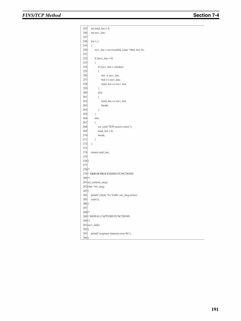
FINS/TCP Method Section 7-4
245 int total_len = 0;
246 int recv_len;
247
248 for (;;)
249
250 recv_len = recv(sockfd, (char *)buf, len, 0);
251
252 if (recv_len > 0)
253
254 if (recv_len < (int)len)
255
256 len -= recv_len;
257 buf += recv_len;
258 total_len += recv_len;
259
260 else
261
262 total_len += recv_len;
263 break;
264
265
266 else
267
268 err_exit("TCP receive error");
269 total_len = 0;
270 break;
271
272
273
274 return total_len;
275
276
277
278 /*
279 *
280 */
281 err_exit(err_msg)
282 char *err_msg;
283
284 printf("client: %s %x¥n",err_msg,errno);
285 exit(1);
286
287
288 /*
289 *
290 */
291 recv_fail()
292
293 printf("response timeout error ¥n");
294
ERROR PROCESSING FUNCTIONS
SIGNAL CAPTURE FUNCTIONS
191
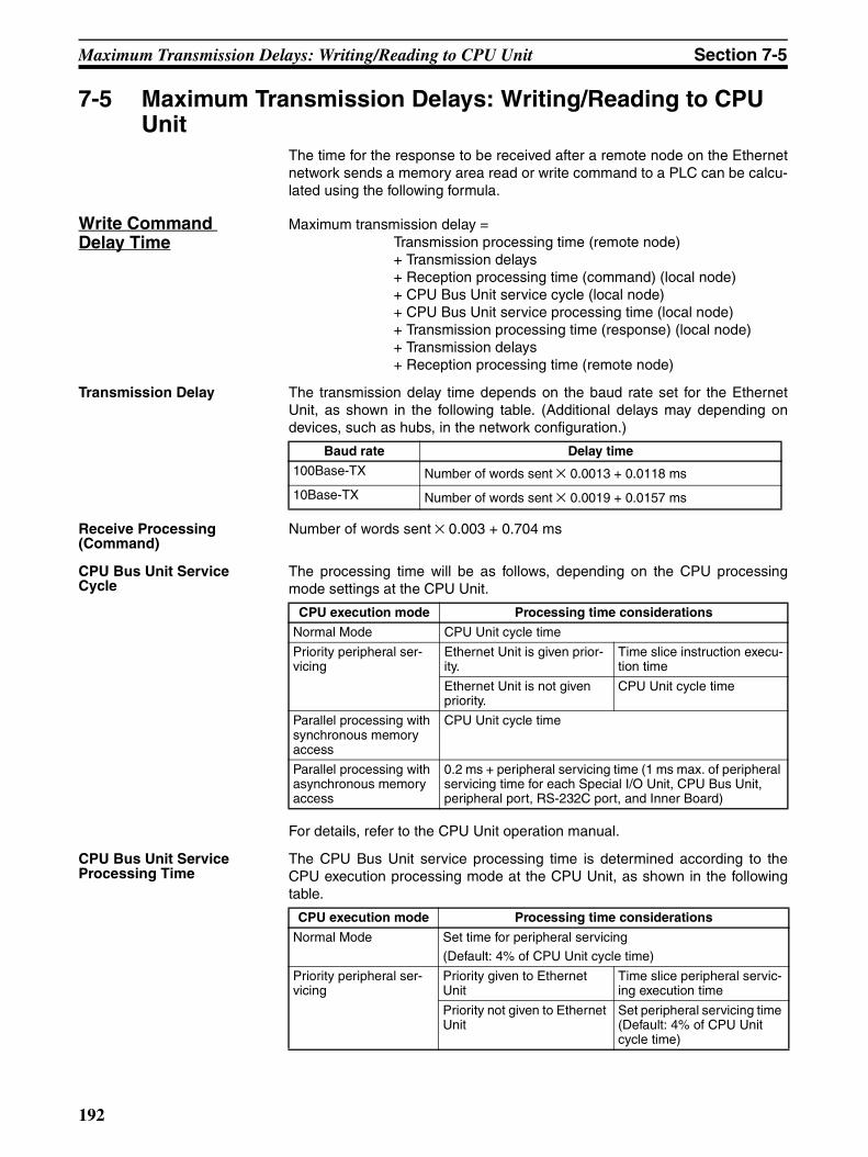
Maximum Transmission Delays: Writing/Reading to CPU Unit Section 7-5
7-5 Maximum Transmission Delays: Writing/Reading to CPU Unit
The time for the response to be received after a remote node on the Ethernetnetwork sends a memory area read or write command to a PLC can be calcu-lated using the following formula.
Write Command Delay Time
Maximum transmission delay =Transmission processing time (remote node)+ Transmission delays+ Reception processing time (command) (local node)+ CPU Bus Unit service cycle (local node) + CPU Bus Unit service processing time (local node)+ Transmission processing time (response) (local node)+ Transmission delays+ Reception processing time (remote node)
Transmission Delay The transmission delay time depends on the baud rate set for the EthernetUnit, as shown in the following table. (Additional delays may depending ondevices, such as hubs, in the network configuration.)
Receive Processing (Command)
Number of words sent × 0.003 + 0.704 ms
CPU Bus Unit Service Cycle
The processing time will be as follows, depending on the CPU processingmode settings at the CPU Unit.
For details, refer to the CPU Unit operation manual.
CPU Bus Unit Service Processing Time
The CPU Bus Unit service processing time is determined according to theCPU execution processing mode at the CPU Unit, as shown in the followingtable.
Baud rate Delay time
100Base-TX Number of words sent × 0.0013 + 0.0118 ms
10Base-TX Number of words sent × 0.0019 + 0.0157 ms
CPU execution mode Processing time considerations
Normal Mode CPU Unit cycle time
Priority peripheral ser-vicing
Ethernet Unit is given prior-ity.
Time slice instruction execu-tion time
Ethernet Unit is not given priority.
CPU Unit cycle time
Parallel processing with synchronous memory access
CPU Unit cycle time
Parallel processing with asynchronous memory access
0.2 ms + peripheral servicing time (1 ms max. of peripheral servicing time for each Special I/O Unit, CPU Bus Unit, peripheral port, RS-232C port, and Inner Board)
CPU execution mode Processing time considerations
Normal Mode Set time for peripheral servicing (Default: 4% of CPU Unit cycle time)
Priority peripheral ser-vicing
Priority given to Ethernet Unit
Time slice peripheral servic-ing execution time
Priority not given to Ethernet Unit
Set peripheral servicing time (Default: 4% of CPU Unit cycle time)
192
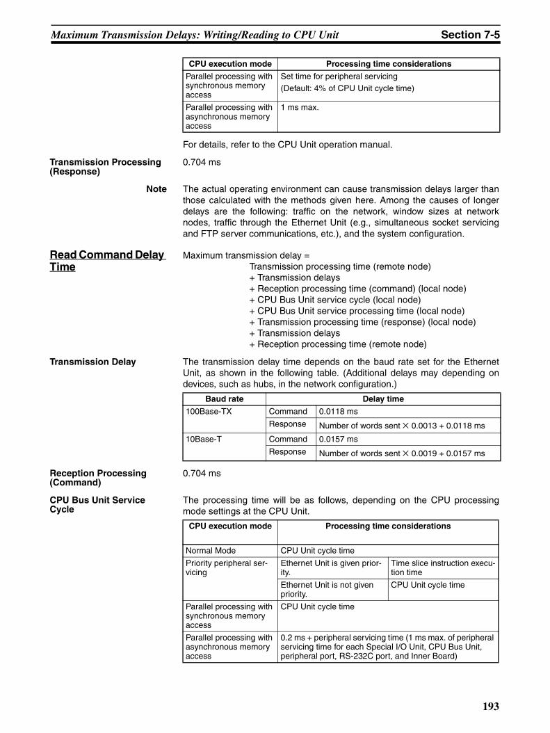
Maximum Transmission Delays: Writing/Reading to CPU Unit Section 7-5
For details, refer to the CPU Unit operation manual.
Transmission Processing (Response)
0.704 ms
Note The actual operating environment can cause transmission delays larger thanthose calculated with the methods given here. Among the causes of longerdelays are the following: traffic on the network, window sizes at networknodes, traffic through the Ethernet Unit (e.g., simultaneous socket servicingand FTP server communications, etc.), and the system configuration.
Read Command Delay Time
Maximum transmission delay =Transmission processing time (remote node)+ Transmission delays+ Reception processing time (command) (local node)+ CPU Bus Unit service cycle (local node) + CPU Bus Unit service processing time (local node)+ Transmission processing time (response) (local node)+ Transmission delays+ Reception processing time (remote node)
Transmission Delay The transmission delay time depends on the baud rate set for the EthernetUnit, as shown in the following table. (Additional delays may depending ondevices, such as hubs, in the network configuration.)
Reception Processing (Command)
0.704 ms
CPU Bus Unit Service Cycle
The processing time will be as follows, depending on the CPU processingmode settings at the CPU Unit.
Parallel processing with synchronous memory access
Set time for peripheral servicing (Default: 4% of CPU Unit cycle time)
Parallel processing with asynchronous memory access
1 ms max.
CPU execution mode Processing time considerations
Baud rate Delay time
100Base-TX Command 0.0118 ms
Response Number of words sent × 0.0013 + 0.0118 ms
10Base-T Command 0.0157 ms
Response Number of words sent × 0.0019 + 0.0157 ms
CPU execution mode Processing time considerations
Normal Mode CPU Unit cycle time
Priority peripheral ser-vicing
Ethernet Unit is given prior-ity.
Time slice instruction execu-tion time
Ethernet Unit is not given priority.
CPU Unit cycle time
Parallel processing with synchronous memory access
CPU Unit cycle time
Parallel processing with asynchronous memory access
0.2 ms + peripheral servicing time (1 ms max. of peripheral servicing time for each Special I/O Unit, CPU Bus Unit, peripheral port, RS-232C port, and Inner Board)
193
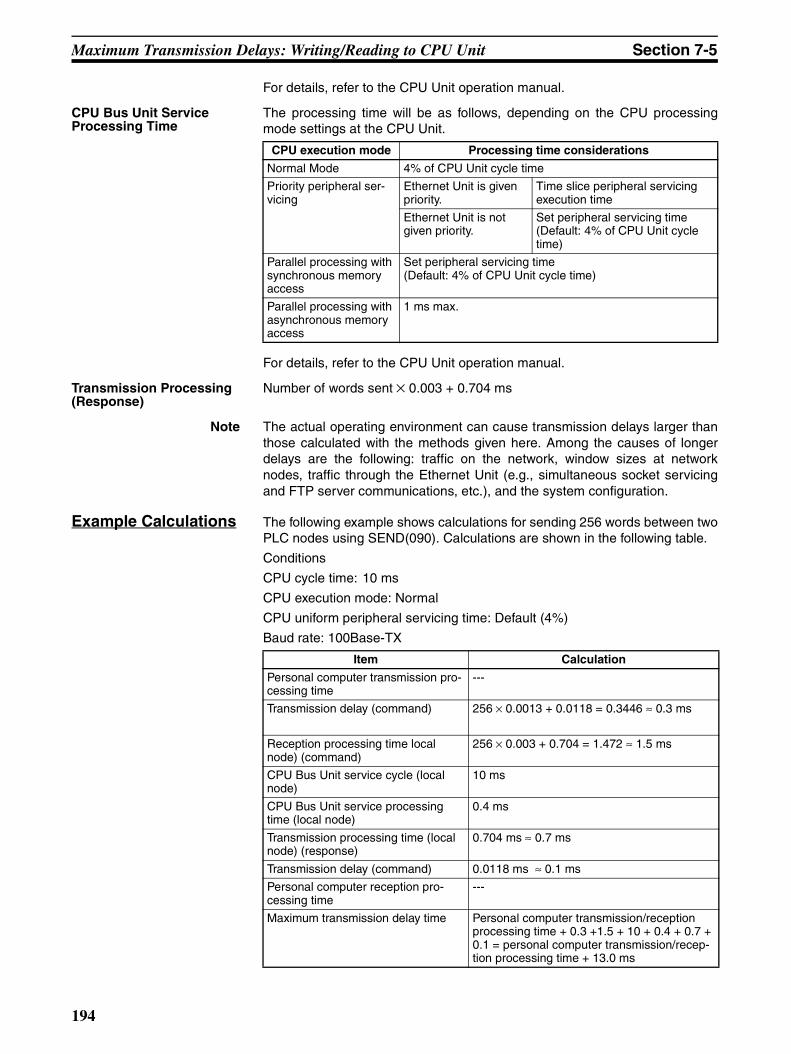
Maximum Transmission Delays: Writing/Reading to CPU Unit Section 7-5
For details, refer to the CPU Unit operation manual.
CPU Bus Unit Service Processing Time
The processing time will be as follows, depending on the CPU processingmode settings at the CPU Unit.
For details, refer to the CPU Unit operation manual.
Transmission Processing (Response)
Number of words sent × 0.003 + 0.704 ms
Note The actual operating environment can cause transmission delays larger thanthose calculated with the methods given here. Among the causes of longerdelays are the following: traffic on the network, window sizes at networknodes, traffic through the Ethernet Unit (e.g., simultaneous socket servicingand FTP server communications, etc.), and the system configuration.
Example Calculations The following example shows calculations for sending 256 words between twoPLC nodes using SEND(090). Calculations are shown in the following table.
Conditions
CPU cycle time: 10 ms
CPU execution mode: Normal
CPU uniform peripheral servicing time: Default (4%)
Baud rate: 100Base-TX
CPU execution mode Processing time considerations
Normal Mode 4% of CPU Unit cycle time
Priority peripheral ser-vicing
Ethernet Unit is given priority.
Time slice peripheral servicing execution time
Ethernet Unit is not given priority.
Set peripheral servicing time (Default: 4% of CPU Unit cycle time)
Parallel processing with synchronous memory access
Set peripheral servicing time (Default: 4% of CPU Unit cycle time)
Parallel processing with asynchronous memory access
1 ms max.
Item Calculation
Personal computer transmission pro-cessing time
---
Transmission delay (command) 256 × 0.0013 + 0.0118 = 0.3446 ≈ 0.3 ms
Reception processing time local node) (command)
256 × 0.003 + 0.704 = 1.472 ≈ 1.5 ms
CPU Bus Unit service cycle (local node)
10 ms
CPU Bus Unit service processing time (local node)
0.4 ms
Transmission processing time (local node) (response)
0.704 ms ≈ 0.7 ms
Transmission delay (command) 0.0118 ms ≈ 0.1 ms
Personal computer reception pro-cessing time
---
Maximum transmission delay time Personal computer transmission/reception processing time + 0.3 +1.5 + 10 + 0.4 + 0.7 + 0.1 = personal computer transmission/recep-tion processing time + 13.0 ms
194
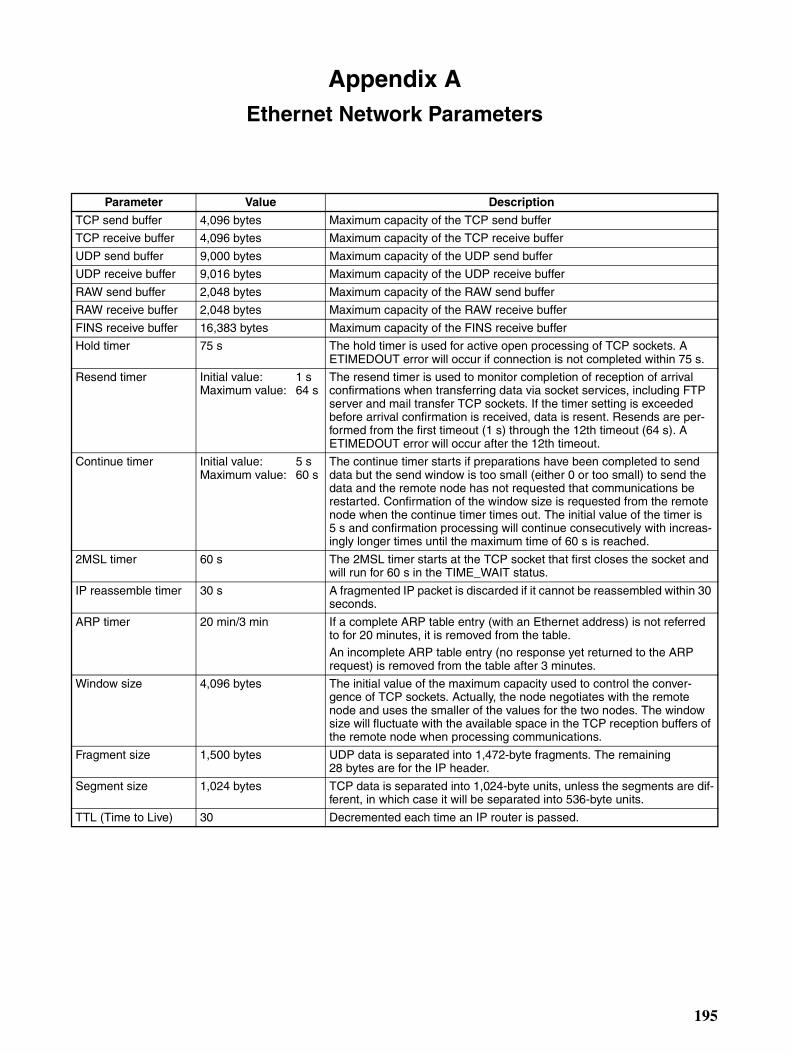
Appendix AEthernet Network Parameters
Parameter Value Description
TCP send buffer 4,096 bytes Maximum capacity of the TCP send buffer
TCP receive buffer 4,096 bytes Maximum capacity of the TCP receive buffer
UDP send buffer 9,000 bytes Maximum capacity of the UDP send buffer
UDP receive buffer 9,016 bytes Maximum capacity of the UDP receive buffer
RAW send buffer 2,048 bytes Maximum capacity of the RAW send buffer
RAW receive buffer 2,048 bytes Maximum capacity of the RAW receive buffer
FINS receive buffer 16,383 bytes Maximum capacity of the FINS receive buffer
Hold timer 75 s The hold timer is used for active open processing of TCP sockets. A ETIMEDOUT error will occur if connection is not completed within 75 s.
Resend timer Initial value: 1 sMaximum value: 64 s
The resend timer is used to monitor completion of reception of arrival confirmations when transferring data via socket services, including FTP server and mail transfer TCP sockets. If the timer setting is exceeded before arrival confirmation is received, data is resent. Resends are per-formed from the first timeout (1 s) through the 12th timeout (64 s). A ETIMEDOUT error will occur after the 12th timeout.
Continue timer Initial value: 5 sMaximum value: 60 s
The continue timer starts if preparations have been completed to send data but the send window is too small (either 0 or too small) to send the data and the remote node has not requested that communications be restarted. Confirmation of the window size is requested from the remote node when the continue timer times out. The initial value of the timer is 5 s and confirmation processing will continue consecutively with increas-ingly longer times until the maximum time of 60 s is reached.
2MSL timer 60 s The 2MSL timer starts at the TCP socket that first closes the socket and will run for 60 s in the TIME_WAIT status.
IP reassemble timer 30 s A fragmented IP packet is discarded if it cannot be reassembled within 30 seconds.
ARP timer 20 min/3 min If a complete ARP table entry (with an Ethernet address) is not referred to for 20 minutes, it is removed from the table.An incomplete ARP table entry (no response yet returned to the ARP request) is removed from the table after 3 minutes.
Window size 4,096 bytes The initial value of the maximum capacity used to control the conver-gence of TCP sockets. Actually, the node negotiates with the remote node and uses the smaller of the values for the two nodes. The window size will fluctuate with the available space in the TCP reception buffers of the remote node when processing communications.
Fragment size 1,500 bytes UDP data is separated into 1,472-byte fragments. The remaining 28 bytes are for the IP header.
Segment size 1,024 bytes TCP data is separated into 1,024-byte units, unless the segments are dif-ferent, in which case it will be separated into 536-byte units.
TTL (Time to Live) 30 Decremented each time an IP router is passed.
195

Ethernet Network Parameters Appendix A
196
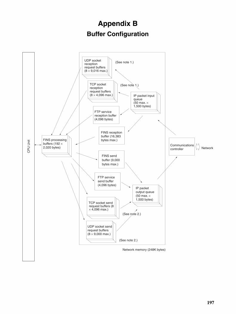
Appendix BBuffer Configuration
Network memory (248K bytes)
Communications controller
IP packet output queue (50 max. × 1,500 bytes)
UDP socket send request buffers (8 × 9,000 max.)
TCP socket send request buffers (8 × 4,096 max.)
FTP service send buffer (4,096 bytes)
FINS send buffer (9,000 bytes max.)
FINS reception buffer (16,383 bytes max.)
FTP service reception buffer (4,096 bytes)
TCP socket reception request buffers (8 × 4,096 max.)
UDP socket reception request buffers (8 × 9,016 max.)
IP packet input queue (50 max. × 1,500 bytes)
Network
(See note 2.)
(See note 2.)
(See note 1.)
(See note 1.)
FINS processing buffers (192 ×2,020 bytes)
CP
U U
nit
197
Buffer Configuration Appendix B
Network MemoryMost of the buffers used for communications servicing by the Ethernet Unit are administered in a buffer config-uration called network memory. Network memory consists of 196K bytes of memory divided into short and longbuffers. The use of short and long buffers is determined by the status of the various services when the EthernetUnit is running. The capacity of all buffers cannot be used due to limits in the mounted memory capacity. Thestatus of the short and long buffers can be accessed by execution the FINS command MEMORY STATUSREAD (2763).
Note 1. The status of UDP and TCP socket reception request buffers can be accessed by executing the FINScommand SOCKET STATUS READ (2764).
The status of UDP and TCP socket send request buffers can be accessed by executing the FINS command
SOCKET STATUS READ (2764).
198
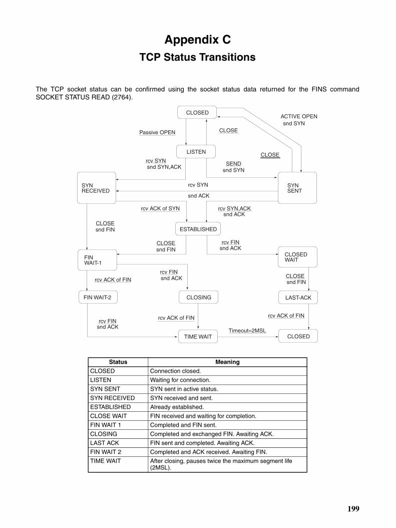
Appendix CTCP Status Transitions
The TCP socket status can be confirmed using the socket status data returned for the FINS commandSOCKET STATUS READ (2764).
Status Meaning
CLOSED Connection closed.
LISTEN Waiting for connection.
SYN SENT SYN sent in active status.
SYN RECEIVED SYN received and sent.
ESTABLISHED Already established.
CLOSE WAIT FIN received and waiting for completion.
FIN WAIT 1 Completed and FIN sent.
CLOSING Completed and exchanged FIN. Awaiting ACK.
LAST ACK FIN sent and completed. Awaiting ACK.
FIN WAIT 2 Completed and ACK received. Awaiting FIN.
TIME WAIT After closing, pauses twice the maximum segment life (2MSL).
rcv FIN
snd ACK
CLOSE
rcv ACK of FIN
rcv ACK of SYN
CLOSED
LISTEN
SYNRECEIVED
SYNSENT
ESTABLISHED
CLOSING
CLOSEDWAIT
CLOSED
snd SYN,ACK
Passive OPEN CLOSE
ACTIVE OPENsnd SYN
snd SYNSEND
CLOSE
rcv SYN
snd ACK
rcv SYN,ACKsnd ACK
snd FINCLOSE
snd ACKrcv FIN
rcv ACK of FIN
snd FIN
rcv FINrcv ACK of FIN
Timeout=2MSL
LAST-ACK
CLOSE
snd FIN
TIME WAIT
FINWAIT-1
FIN WAIT-2
rcv SYN
snd ACK
199

TCP Status Transitions Appendix C
200

Appendix DASCII Characters
Bits 1 to 4 Bits 5 to 7
Binary 0000 0001 0010 0011 0100 0101 0110 0111
Hex 0 1 2 3 4 5 6 7
0000 0 NUL DLE Space 0 @ P p0001 1 SOH DC1 ! 1 A Q a q0010 2 STX DC2 ” 2 B R b r0011 3 ETX DC3 # 3 C S c s0100 4 EOT DC4 $ 4 D T d t0101 5 ENQ NAK % 5 E U e u0110 6 ACK SYN & 6 F V f v0111 7 BEL ETB ’ 7 G W g w1000 8 BS CAN ( 8 H X h x1001 9 HT EM ) 9 I Y i y1010 A LF SUB * : J Z j z1011 B VT ESC + ; K [ k 1100 C FF FS , < L \ l |1101 D CR GS - = M ] m 1110 E SO RS . > N ^ n ~1111 F SI US / ? O _ o DEL
201

ASCII Characters Appendix D
202
Appendix EMaintenance
The Ethernet Unit makes up part of a network. Repair a defective Ethernet Unit as soon as possible as it canhave a negative effect on the entire network. We recommend that customers keep one or more spare EthernetUnits to allow immediate recovery of the network.
Replacing an Ethernet UnitObserve the following precautions when replacing the Ethernet Unit.
• Always turn OFF the power supply before replacing the Ethernet Unit.
• Check that the spare Ethernet Unit is operating normally before replacing a defective Unit with it.
• When returning a defective Unit for repairs, provide as much written information as possible on the symp-toms of the problem.
• If a problem occurs with poor contacts, wipe the contacts with a clean cloth soaked with industrial alcohol.Carefully remove any lint remaining on the contacts before replacing the Unit.
Settings after Replacing an Ethernet UnitAfter replacing an Ethernet Unit, set the following to the same settings as were used on the previous Unit.
• Unit number
• Node address
Settings After Replacing a CPUThe EEPROM in the PLC’s CPU holds the information listed below. This information must be stored in any newCPU used to replace a defective one.
• Routing tables
• System Setup for the Ethernet Unit
203

Maintenance Appendix E
204
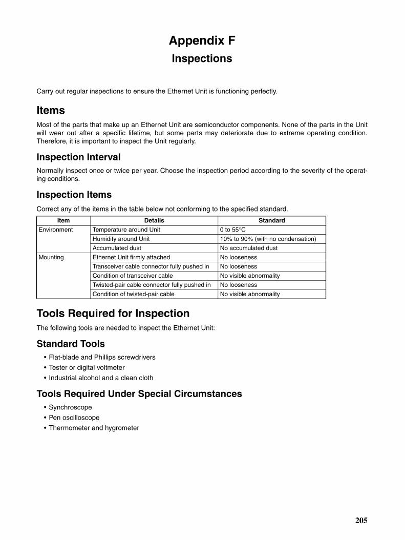
Appendix FInspections
Carry out regular inspections to ensure the Ethernet Unit is functioning perfectly.
ItemsMost of the parts that make up an Ethernet Unit are semiconductor components. None of the parts in the Unitwill wear out after a specific lifetime, but some parts may deteriorate due to extreme operating condition.Therefore, it is important to inspect the Unit regularly.
Inspection IntervalNormally inspect once or twice per year. Choose the inspection period according to the severity of the operat-ing conditions.
Inspection ItemsCorrect any of the items in the table below not conforming to the specified standard.
Tools Required for InspectionThe following tools are needed to inspect the Ethernet Unit:
Standard Tools• Flat-blade and Phillips screwdrivers
• Tester or digital voltmeter
• Industrial alcohol and a clean cloth
Tools Required Under Special Circumstances• Synchroscope
• Pen oscilloscope
• Thermometer and hygrometer
Item Details Standard
Environment Temperature around Unit 0 to 55°CHumidity around Unit 10% to 90% (with no condensation)
Accumulated dust No accumulated dust
Mounting Ethernet Unit firmly attached No looseness
Transceiver cable connector fully pushed in No looseness
Condition of transceiver cable No visible abnormality
Twisted-pair cable connector fully pushed in No looseness
Condition of twisted-pair cable No visible abnormality
205

Inspections Appendix F
206
Index
Numerics100Base-TX
transmission delays, 193
10Base-T
transmission delays, 193
AAccessing Memory/Receiving Mail Flag, 60
Accessing Memory/Sending Mail Flag, 26
Account Name field, 6, 19, 39
Adjust Time field, 92, 93
applications
examples
mail send function, 30
using UNIX, 86
precautions, xxiv
ASCII characters, 201
Attached file name field, 20, 23
Attached file type field, 23
attached files
extensions
CSV, 15, 61
IOM, 15, 60
TXT, 15, 61
file data, 15
I/O memory data, 15
mail send function, 17
transfer times, 28, 62
Auto Adjust Time field, 92, 93
Auto Adjust Time Tab, 92, 93
automatic clock adjustment, 2, 3Automatic Clock Adjustment Switch, 94
errors
error codes, 95
error log, 95
SNTP, 94
troubleshooting with indicators, 94
overview, 90
procedure, 91
requirements, 90
settings, 92
specifications, 91
Bbaud rate
transmission delays, 193
Bit value change field, 24
bits
Automatic Clock Adjustment Switch, 94
dedicated control bits, 103
Socket Service Request Switches, 119
Close Request Switch, 120
Send Request Switch, 119
TCP Active Open Request Switch, 119
TCP Passive Open Request Switch, 119
UDP Open Request Switch, 119
buffers, 195
configuration, 197
bye command, 68, 73, 77
Ccd command, 68, 73, 75
cdup command, 68, 73
ChangeMode command, 2, 35
command/response format, 53
ChangeMode field, 41
CJ1W-ETN11
mail send function comparison, 11
clock
automatic adjustment, 2, 3close command, 68, 73, 77
Close Request Switch, 120
CMND(490) instruction, 99
requesting socket services, 105, 135
commands
FTP commands, 73
remote mail commands, 42
communications cables, xxv
CPU Bus Unit Setup
transferring settings, 32
CPU Bus Units
precautions, xxvi
CPU condition field, 24
crimp terminals, xxv
CS1W-ETN01/11
mail send function comparison, 11
CSV field, 41
CSV format, 15, 27, 61
Custom 1 to 3 field, 41
CX-Programmer
Unit Setup, 30
207

Index
Ddelete command, 68, 73, 77
dir command, 68, 73, 74
DNS communications, 3DNS server, 31
automatic clock adjustment
errors, 94
DNS Tab, 7, 19, 39, 92
initial settings, 31
EEC Directives, xxvi
electromagnetic fields, xxiv
EM File Memory, 80
using, 80
attached files, 16, 17, 35
receiving, 41
body, 16, 17, 36
command line, 37
compression, 17, 37
data sent, 22
decoding, 37
destination e-mail-address, 17
encoding, 17
encryption, 17, 37
errors
troubleshooting, 28
Ethernet Unit information, 13
header information, 13
protection, 40
protocols, 17
reception timing, 35
remote mail commands, 35
responses, 37
send conditions, 17
send status, 17
specifications, 17
status information, 15
subject line, 17, 36
triggers, 13, 17, 18, 23
user-set information, 14
EMC Directives, xxvi
EMI Standard, xxvi
EMS Standard, xxvi
encoding
mail send function, 17
encryption, 17, 37
ERC indicator
error display, 29
ERH indicator
error display, 29
error log
error codes, 29
ErrorLogClear command, 36
command/response format, 55
ErrorLogClear field, 41
ErrorLogRead command, 2, 36
command/response format, 54
ErrorLogRead field, 41
errors
automatic clock adjustment, 94
error codes
mail send function, 29
error messages, 78
mail receive function, 63
mail send function, 28
troubleshooting
using indicators, 29
Ethernet communications
network parameters, 195
parameters, 195
Ethernet Units
communications services, 2replacing, 203
resetting, 203
ETN condition field, 24
FFALS instruction, xxiii
file data, 16
file extensions
CSV, 15
IOM, 15
TXT, 15
FileDelete command, 36
command/response format, 45
FileDelete field, 41
FileList command, 2, 36
command/response format, 46
FileList field, 41
FileRead command, 2, 36
command/response format, 44
FileRead field, 41
208

Index
FileWrite command, 2, 36
command/response format, 43
FileWrite field, 41
FINS communications, 2, 4address conversion, 161
application layers, 160
commands
CONNECTION CONFIRMATION, 180
FINS FRAME SEND, 179
FINS FRAME SEND ERROR NOTIFICATION, 179
FINS NODE ADDRESS DATA SEND (CLIENT TOSERVER), 177
FINS NODE ADDRESS DATA SEND (SERVER TOCLIENT), 177
FINS frames, 162
format, 162
headers, 162
FINS/TCP method, 160, 171
connection sequences, 181
connection status, 173
FINS node address auto allocation, 174
frame format, 172
headers, 177
procedure, 173, 176
programming example, 185
sending commands, 184
TCP port number, 172
FINS/UDP method, 163
frame format, 164
procedure, 165
programming example, 167
sending commands, 166
UDP port numbers, 164
message length, 161
port numbers, 161
protection, 161
protocols, 161
specifications, 161
using FINS/TCP, 161
using FINS/UDP, 161
FINS node addresses
automatic allocation, 174
connection sequence, 182
FinsSend command, 2, 36
command/response format, 59
FinsSend field, 42
flags
Accessing Memory/Receiving Mail Flag, 60
Accessing Memory/Sending Mail Flag, 26
FTP Status Flag, 79
Port Enabled Flag, 138
FREAD instruction, 27, 60
FTP communications, 4FTP indicator, 79
FTP server, 2, 3application examples, 72
using UNIX, 86
closing, 77
commands, 73
bye, 77
cd, 75
close, 77
delete, 77
dir, 74
get, 76
ls, 74
mdelete, 77
mget, 76
mput, 76
open, 73
put, 76
pwd, 75
quitting, 77
type, 76
user, 74
connecting, 69, 73
data type, 76
displaying current directory, 75
file types, 69
protection, 68
protocol, 68
quitting, 77
See also Memory Cards
specifications, 68
status, 79
FTP Status Flag, 79
FWRIT instruction, 27, 60
Gget command, 68, 73, 76, 85
Get the time information from the SNTP server field, 92, 93
HHOST indicator
error display, 29
Host name field, 5, 6, 19, 39, 92, 93
209

Index
II/O memory data, 15
CSV format, 61
IOM format, 60
TXT format, 61
I/O tables
creating, 30
ICF, 162
inspections, 205
installation
location, xxiv
Interval time field, 20, 24
IO memory data field, 20, 23
IOM field, 41
IOM format, 15, 26
IOMRead command, 2, 35
command/response format, 51
IOMRead field, 41
IOMWrite command, 2, 35
command/response format, 49
IOMWrite field, 41
IP Address field, 5, 7, 19, 39, 92, 93
IP communications
IP addresses
remote devices, 117
programming examples, 127, 131, 140, 148
LLNK indicator
error display, 29
Local mail address field, 4, 19, 39
locking devices
precautions, xxv
Login field, 71
Low Voltage Directive, xxvi
ls command, 68, 73, 74
MMail address 1 field, 19, 21
Mail address 2 field, 19, 21
Mail address field, 20, 22, 39, 40
Mail Address Tab, 19, 21, 31
Mail password field, 6, 19, 39
mail receive function, 2
access times for CPU Units, 62
advantages, 34
attached files, 35, 37
settings, 40
transfer times, 62
command parameters, 35
compression, 37
configuration, 34
decoding, 37
E-mail body, 36
encryption, 37
errors, 63
initial settings, 65
introduction, 34
procedure, 38
protection, 37, 40
protocols, 36
reception timing, 35
remote mail commands, 35
response codes, 59
settings, 39
DNS Tab, 39
POP Tab, 39
Receive Mail Tab, 39
SMTP Tab, 39
SMTP settings, 4specifications, 36
status, 60
mail send function, 2, 3access times for CPU Units, 28
advantages, 10
application example, 30
attached files, 10, 15, 17, 23
transfer times, 28
body, 17
comparison with earlier versions, 11
compatibility, 11
compression, 17
conditions, 11, 22
data sent, 22
destination e-mail address, 17
E-mail contents, 12
E-mail header, 13
encryption, 17
error log, 15
error codes, 29
errors, 28
troubleshooting with indicators, 29
Ethernet Unit information, 14
procedure, 18
protocols, 17
send conditions, 17
210

Index
send timing, 11
sending method (encoding), 17
settings, 19
DNS Tab, 19
Mail Address Tab, 19
POP Tab, 19
SMTP Tab, 19
SMTP settings, 4status, 17, 25
Send Mail Status 1, 25
Send Mail Status 2, 25
status information, 15
subject, 17
triggers, 13, 17, 18, 23
user-set information, 14
Mail Send Switch, 26
MailLogClear command, 36
command/response format, 57
MailLogClear field, 42
MailLogRead command, 36
command/response format, 56
MailLogRead field, 41
maintenance, 203
inspections, 205
mdelete command, 68, 73, 77
Memory Cards, 69, 80
deleting files, 77
displaying directories, 74
See also FTP server
sending stored files, 16
transferring files from host, 76
transferring files to host, 76
mget command, 68, 73, 76
mkdir command, 68, 73
mput command, 68, 73, 76
MRES, 138
Nnetworks
network memory, 198
network parameters, 195
noise, xxiv
OOBJ field, 41
online editing, xxiii
open command, 68, 73
operating environment
precautions, xxiv
PPARAMBackup command, 2, 36
command/response format, 48
PARAMBackup field, 41
Password field, 71
Periodic timer field, 24
POP communications, 3POP Tab, 5, 39
initial settings, 65
POP3 communications, 36
POP3 server, 7Port Enabled Flag, 138
Port No. field, 5, 7, 19, 39, 71, 92, 93
port numbers
sockets, 99
TCP port, 117
remote device, 118
UDP port, 117
remote device, 118
power supply, xxiv
precautions, xxv
precautions, xxi
applications, xxiv
general, xxii
inspections, 205
operating environment, xxiv
power supply, xxv
replacing Units, 203
safety, xxii
Socket Service Request Switches, 155
socket services, 154
TCP communications, 102
UDP communications, 102
Protect using mail address field, 40
protocols
DNS, 3FINS, 4FTP, 4FTP server, 68
POP, 3POP3, 36
SMTP, 3, 17, 37
SNTP, 4table, 3
211
Index
TCP/IP, 4UDP/IP, 4
put command, 68, 73, 76, 85
pwd command, 68, 73, 75
Qquit command, 68, 73, 77
Rradioactivity, xxiv
READ DATA FILE (FREAD) instruction, 27, 60
Receive file with specified extension only field, 39, 41
Receive Mail Tab, 39, 40
Receive Request Switch, 119
Receive specified commands only field, 39, 41
remote mail commands
accessing CPU Unit’s I/O memory area, 35
changing the CPU Unit’s operating mode, 35
command/response format, 42
file memory operations, 36
mail receive function
initial settings, 66
performing an e-mail send/receive test, 36
reading/clearing the e-mail log, 36
reading/clearing the error log, 36
response codes, 59
sending, 66
sending FINS commands, 36
rename command, 68, 73
replacing Units
precautions, xxv
response codes
remote mail commands, 59
Results Storage Area, 138
Socket Service Request Switches, 120
Results Storage Area, 138
Retry timer field, 7, 19, 39, 92, 93
rmdir command, 68, 73
routing tables
precautions, xxvi
RUN indicator
error display, 29
Ssafety precautions, xxii
Send Error Log information field, 20, 23
Send file data or I/O memory data field, 23
Send Mail Status words, 25
Send Mail Tab, 20, 21, 31
Send mail upon trigger field, 22
Send Request Switch, 119
Send status information field, 20, 23
Send user data field, 20, 22
Server access interval time field, 6, 19, 39
Server specification type field, 4, 6, 19, 39, 92, 93
Setup Tab, 71
short-circuits
precautions, xxv
SMTP communications, 3, 37
SMTP server, 7, 30
SMTP Tab, 4, 19, 39
initial settings, 30
SNTP communications, 4SNTP server, 2, 7
automatic clock adjustment
errors, 94
obtaining clock information, 90
socket services, 2, 3applications, 135
CIO Area allocations, 110
functions, 103
parameters, 113
precautions, 154
Socket Service Parameter Area, 104, 113
Socket Service Request Switches, 103, 119
application procedure, 113
precautions, 155
Socket Status Area, 114
TCP communications, 105
parameters, 116
TCP sockets
status, 110
timing charts, 125, 138
UDP communications, 105
parameters, 116
UDP sockets
status, 110
using CMND(490) instruction, 103, 105, 135
using Socket Service Request Switches, 104
SOCKET STATUS READ(2764), 199
sockets
opening, 100
overview, 99
port numbers, 99
212

Index
TCP
status, 199
TCP sockets, 184
number, 117
status, 199
UDP socket
number, 117
UDP sockets, 166
Software switch field, 24
specifications
FTP server, 68
mail receive function, 36
mail send function, 17
SRES, 138
static electricity, xxiv
precautions, xxv
STD field, 41
switches
Socket Service Request Switches, 119
TTCP Active Open Request Switch, 119
TCP communications
comparison with UDP, 100
data fragmentation, 102
precautions, 102
programming example, 127, 140
socket services
parameters, 116
sockets, 100
status, 199
status transitions, 199
TCP Passive Open Request Switch, 119
terminal blocks, xxiii
Test command, 36
command/response format, 58
Test field, 42
timers, 195
timing
socket communications, 138
socket services, 138
transmission
delays, 192
Trigger No. field, 22
Trigger type field, 20
triggers, 13, 17, 18, 23
conditions, 13
TXT field, 41
TXT format, 15, 27, 61
type command, 68, 73, 76
UUDP communications
comparison with TCP, 100
data fragmentation, 102
precautions, 102
programming example, 131, 148
socket services
parameters, 116
UDP Open Request Switch, 119
UDP/IP communications, 4UMBackup command, 2, 36
command/response format, 47
UMBackup field, 41
UNIX
application examples, 86
socket port numbers, 99
Use POP before SMTP field, 5, 19, 39
user command, 68, 73, 74
user name
specifying, 74
User-defined mail address field, 22
WWord value change field, 24
WRITE DATA FILE (FWRIT) instruction, 27, 60
213

Index
214
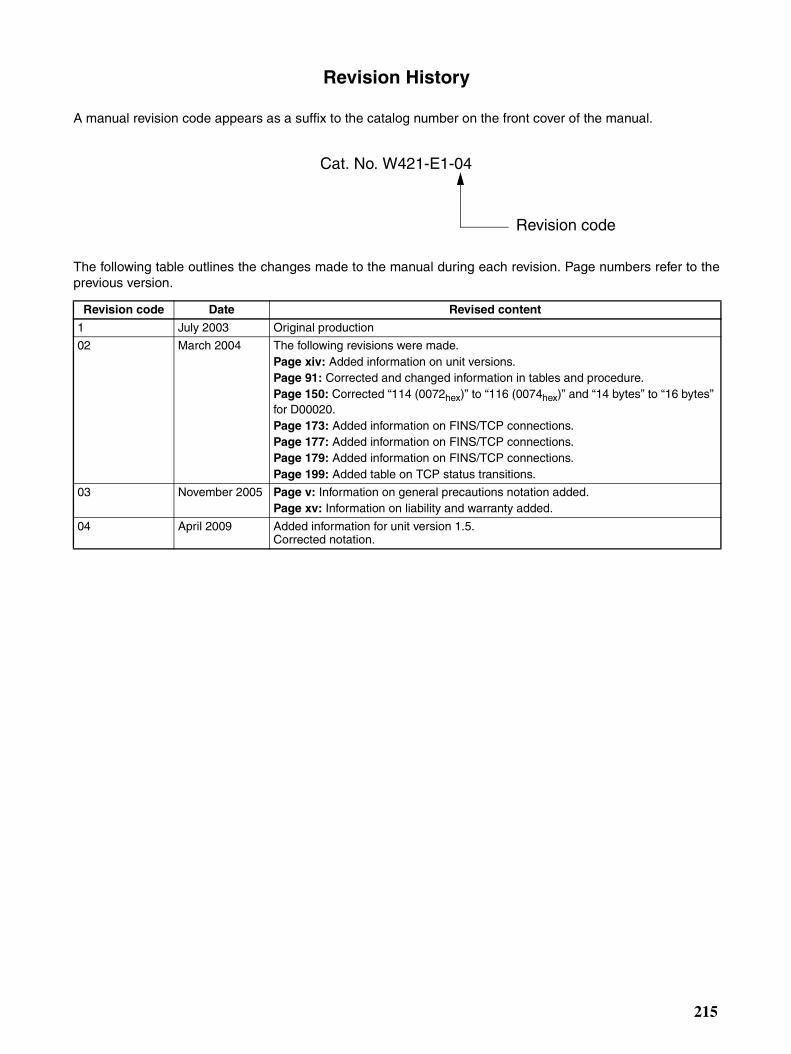
Revision History
A manual revision code appears as a suffix to the catalog number on the front cover of the manual.
The following table outlines the changes made to the manual during each revision. Page numbers refer to theprevious version.
Revision code Date Revised content
1 July 2003 Original production
02 March 2004 The following revisions were made.Page xiv: Added information on unit versions.Page 91: Corrected and changed information in tables and procedure.Page 150: Corrected “114 (0072hex)” to “116 (0074hex)” and “14 bytes” to “16 bytes” for D00020. Page 173: Added information on FINS/TCP connections.Page 177: Added information on FINS/TCP connections.Page 179: Added information on FINS/TCP connections.Page 199: Added table on TCP status transitions.
03 November 2005 Page v: Information on general precautions notation added.Page xv: Information on liability and warranty added.
04 April 2009 Added information for unit version 1.5.Corrected notation.
Cat. No. W421-E1-04
Revision code
215

Revision History
216


OMR
OMRIndus
RegioOMROWegaThe NTel: (3
ContrAutomAutomShiokKyotoTel: (8
Authorized Distributor:ON Corporationtrial Automation Company
nal Headquarters
OMRON ELECTRONICS LLCOne Commerce Drive Schaumburg, IL 60173-5302 U.S.A.Tel: (1) 847-843-7900/Fax: (1) 847-843-7787
OMRON ASIA PACIFIC PTE. LTD.No. 438A Alexandra Road # 05-05/08 (Lobby 2), Alexandra Technopark, Singapore 119967Tel: (65) 6835-3011/Fax: (65) 6835-2711
ol Devices Division H.Q.ation & Drive Divisionation Department 1
oji Horikawa, Shimogyo-ku,, 600-8530 Japan1) 75-344-7084/Fax: (81) 75-344-7149
In the interest of product improvement, specifications are subject to change without notice.
Cat. No. W421-E1-04ON Industrial Automation Global: www.ia.omron.comPrinted in Japan
0409
N EUROPE B.V.laan 67-69-2132 JD Hoofddorpetherlands1)2356-81-300/Fax: (31)2356-81-388
OMRON (CHINA) CO., LTD.Room 2211, Bank of China Tower, 200 Yin Cheng Zhong Road, PuDong New Area, Shanghai, 200120, ChinaTel: (86) 21-5037-2222/Fax: (86) 21-5037-2200
© OMRON Corporation 2003 All Rights Reserved.