Embed Size (px)
Citation preview
Software Design (UML) © SERG
Software Design
Static Modeling using theUnified Modeling Language
(UML)
Material based on [Booch99, Rambaugh99, Jacobson99, Fowler97, Brown99]
Software Design (UML) © SERG
Classes
ClassName
attributes
operations
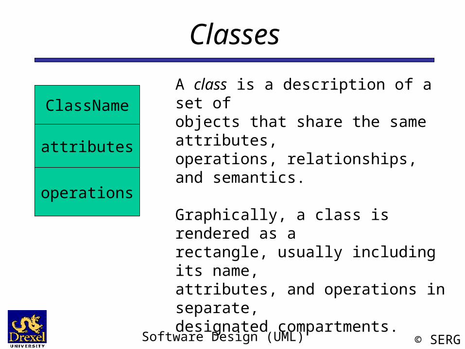
A class is a description of a set of objects that share the same attributes,operations, relationships, and semantics.
Graphically, a class is rendered as a rectangle, usually including its name,attributes, and operations in separate,designated compartments.
Software Design (UML) © SERG
Class Names
ClassName
attributes
operations
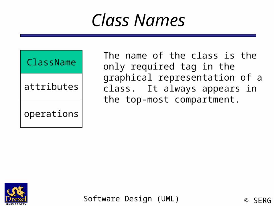
The name of the class is the only required tag in the graphical representation of a class. It always appears in the top-most compartment.
Software Design (UML) © SERG
Class Attributes
Person
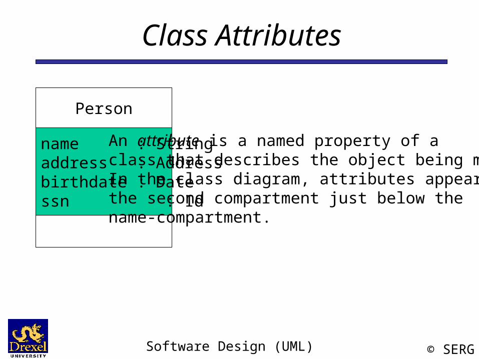
name : Stringaddress : Addressbirthdate : Datessn : Id
An attribute is a named property of a class that describes the object being modeled.In the class diagram, attributes appear in the second compartment just below the name-compartment.
Software Design (UML) © SERG
Class Attributes (Cont’d)
Person
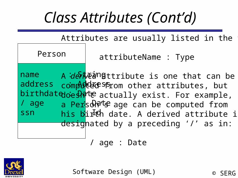
name : Stringaddress : Addressbirthdate : Date/ age : Datessn : Id
Attributes are usually listed in the form:
attributeName : Type
A derived attribute is one that can becomputed from other attributes, butdoesn’t actually exist. For example,a Person’s age can be computed from his birth date. A derived attribute is designated by a preceding ‘/’ as in:
/ age : Date
Software Design (UML) © SERG
Class Attributes (Cont’d)
Person
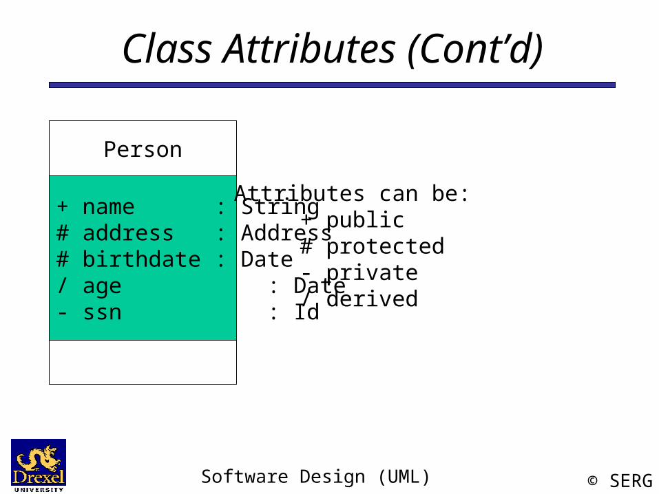
+ name : String# address : Address# birthdate : Date/ age : Date- ssn : Id
Attributes can be:+ public# protected- private/ derived
Software Design (UML) © SERG
Class Operations
Person
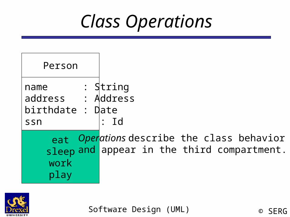
name : Stringaddress : Addressbirthdate : Datessn : Id
eatsleepworkplay
Operations describe the class behavior and appear in the third compartment.
Software Design (UML) © SERG
Class Operations (Cont’d)
PhoneBook
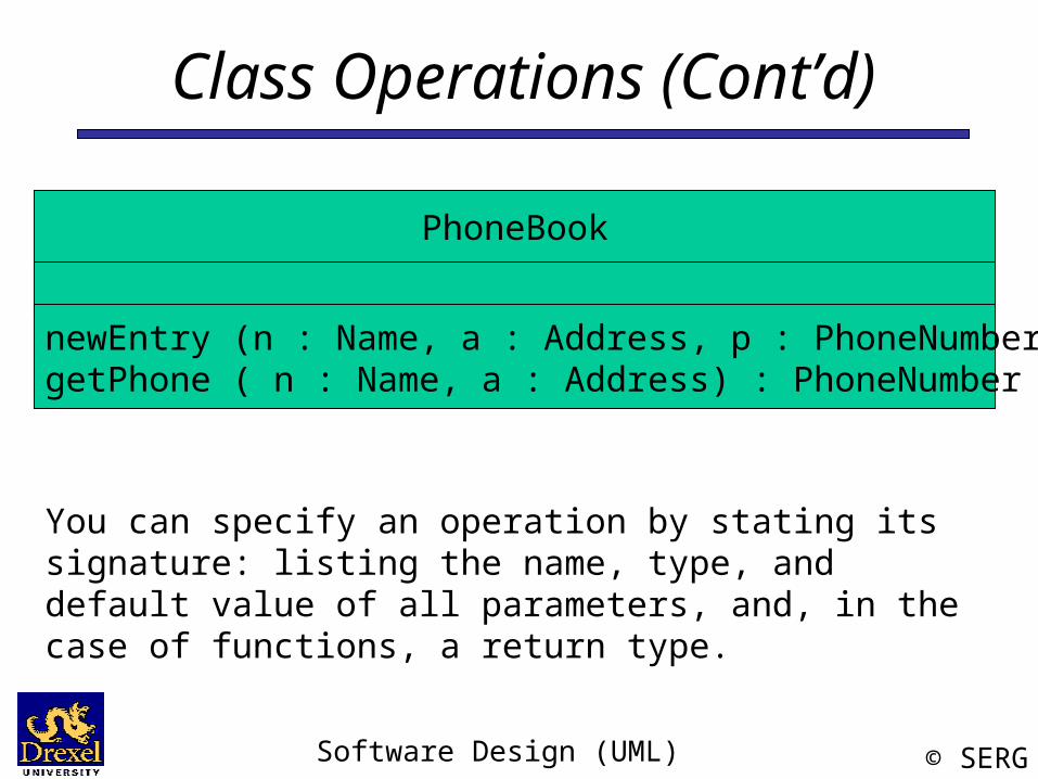
newEntry (n : Name, a : Address, p : PhoneNumber, d : Description)getPhone ( n : Name, a : Address) : PhoneNumber
You can specify an operation by stating its signature: listing the name, type, and default value of all parameters, and, in the case of functions, a return type.
Software Design (UML) © SERG
Depicting Classes
Person
name : Stringbirthdate : Datessn : Id
eat()sleep()work()play()
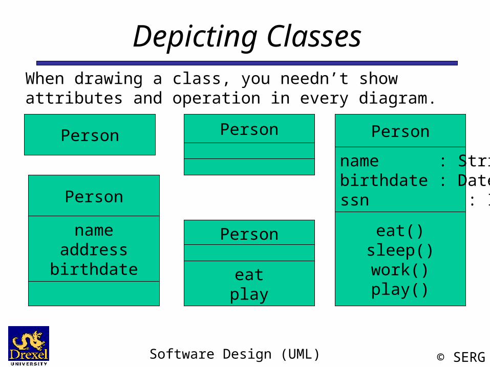
When drawing a class, you needn’t show attributes and operation in every diagram.
Person
Person
nameaddress
birthdate
Person
eatplay
Person
Software Design (UML) © SERG
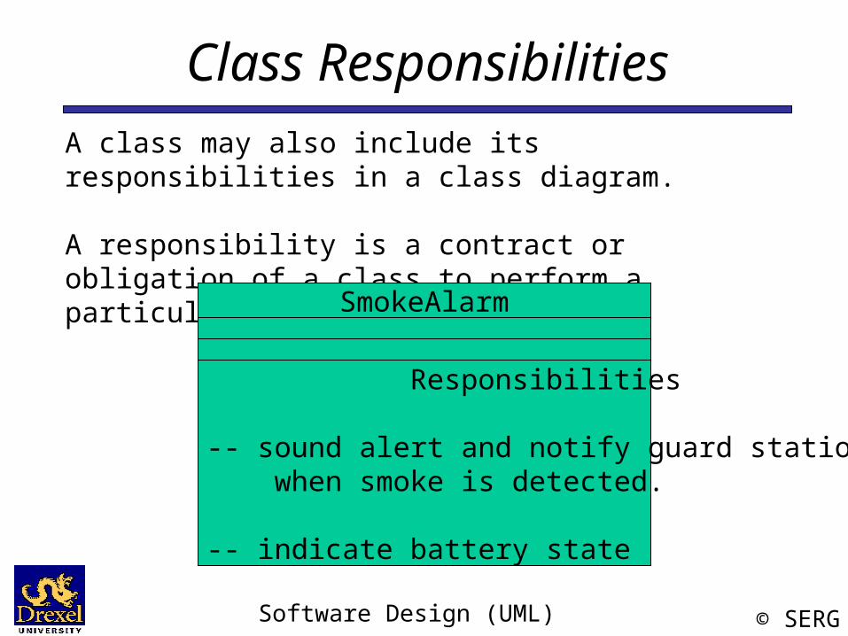
Class ResponsibilitiesA class may also include its responsibilities in a class diagram.
A responsibility is a contract or obligation of a class to perform a particular service.
SmokeAlarm
Responsibilities
-- sound alert and notify guard station when smoke is detected.
-- indicate battery state
Software Design (UML) © SERG
Relationships
In UML, object interconnections (logical or physical), are modeled as relationships.
There are three kinds of relationships in UML:
• dependencies
• generalizations
• associations
Software Design (UML) © SERG
Dependency Relationships
CourseSchedule
add(c : Course)remove(c : Course)
Course
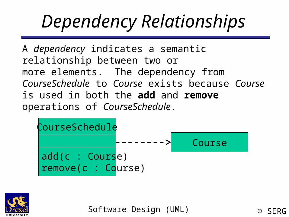
A dependency indicates a semantic relationship between two ormore elements. The dependency from CourseSchedule to Course exists because Course is used in both the add and remove operations of CourseSchedule.
Software Design (UML) © SERG
Generalization Relationships
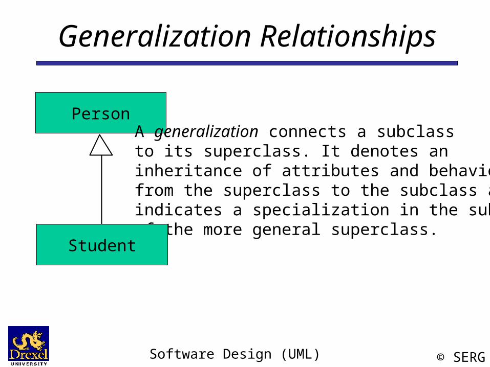
PersonA generalization connects a subclassto its superclass. It denotes an inheritance of attributes and behaviorfrom the superclass to the subclass andindicates a specialization in the subclassof the more general superclass.
Student
Software Design (UML) © SERG
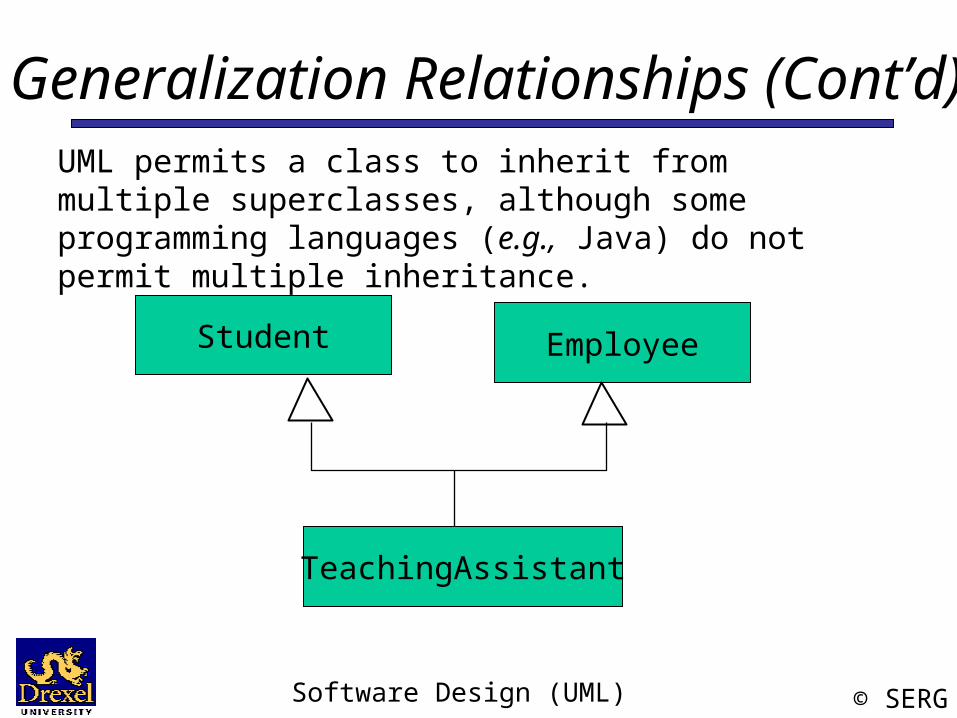
Generalization Relationships (Cont’d)
Student
UML permits a class to inherit from multiple superclasses, although some programming languages (e.g., Java) do not permit multiple inheritance.
TeachingAssistant
Employee
Software Design (UML) © SERG
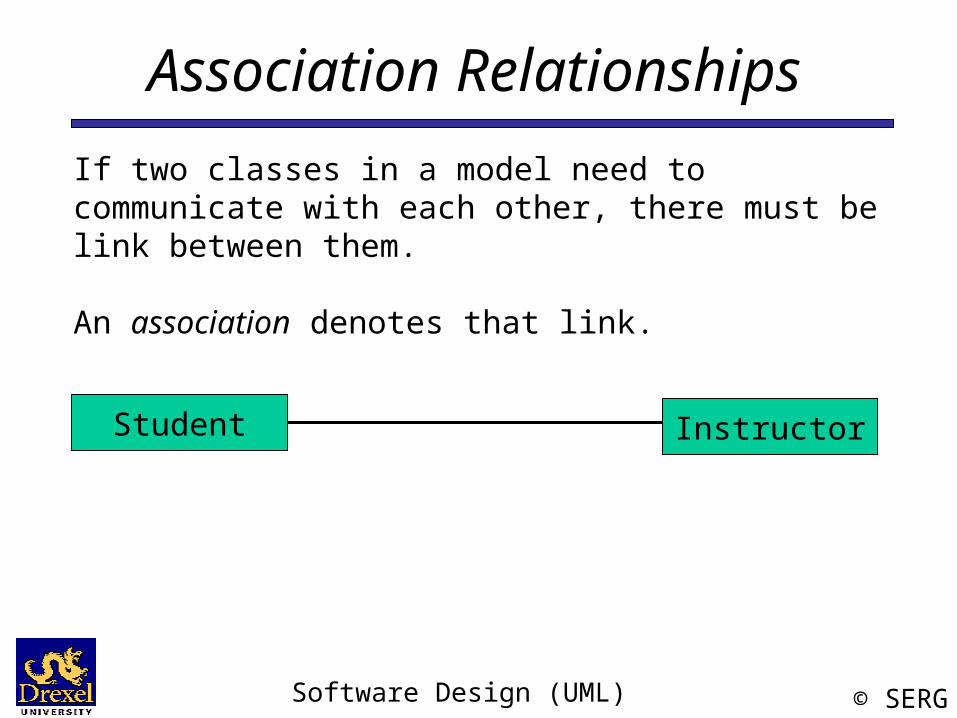
Association RelationshipsIf two classes in a model need to communicate with each other, there must be link between them.
An association denotes that link.
InstructorStudent
Software Design (UML) © SERG
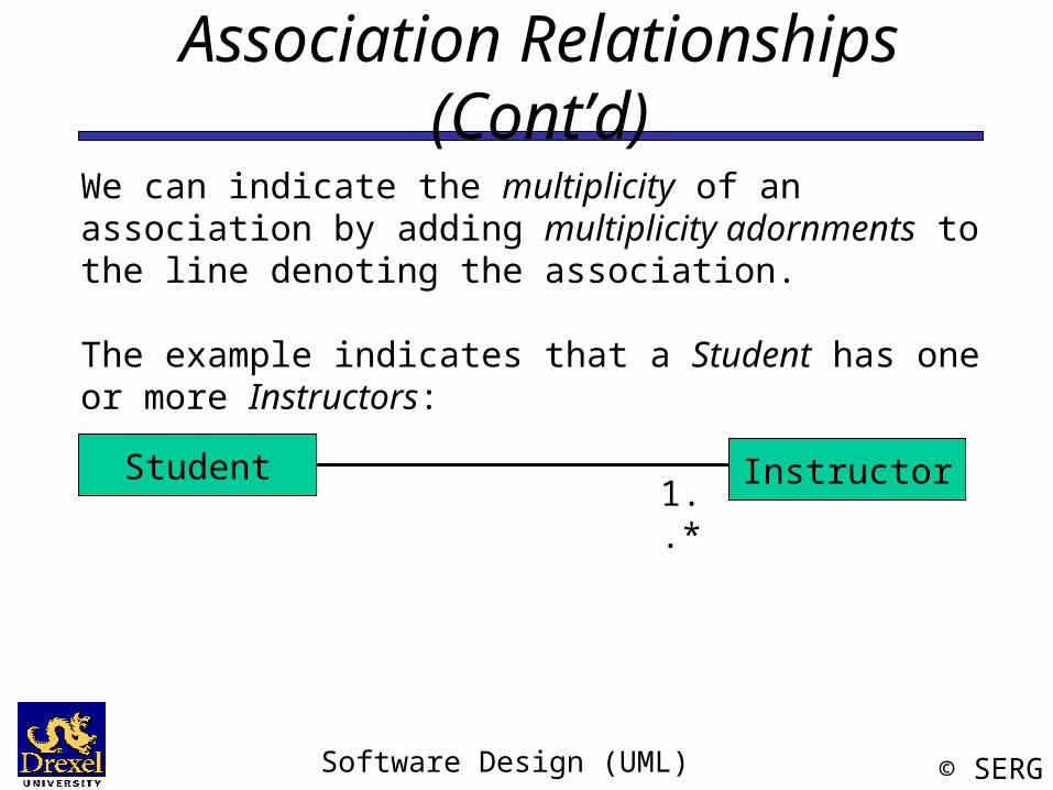
Association Relationships (Cont’d)We can indicate the multiplicity of an association by adding multiplicity adornments to the line denoting the association.
The example indicates that a Student has one or more Instructors:
InstructorStudent1..*
Software Design (UML) © SERG
Association Relationships (Cont’d)
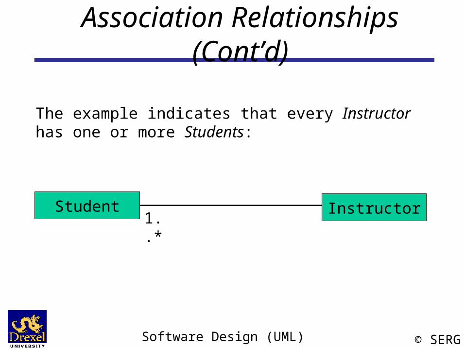
The example indicates that every Instructor has one or more Students:
InstructorStudent1..*
Software Design (UML) © SERG
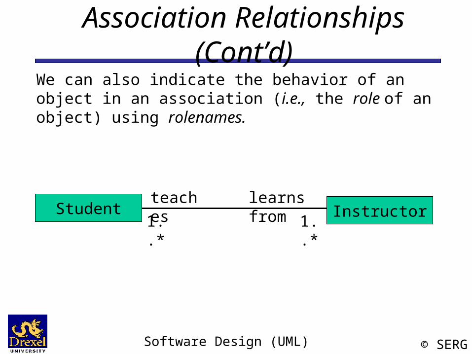
Association Relationships (Cont’d)We can also indicate the behavior of an object in an association (i.e., the role of an object) using rolenames.
InstructorStudent1..*1..*
learns fromteaches
Software Design (UML) © SERG
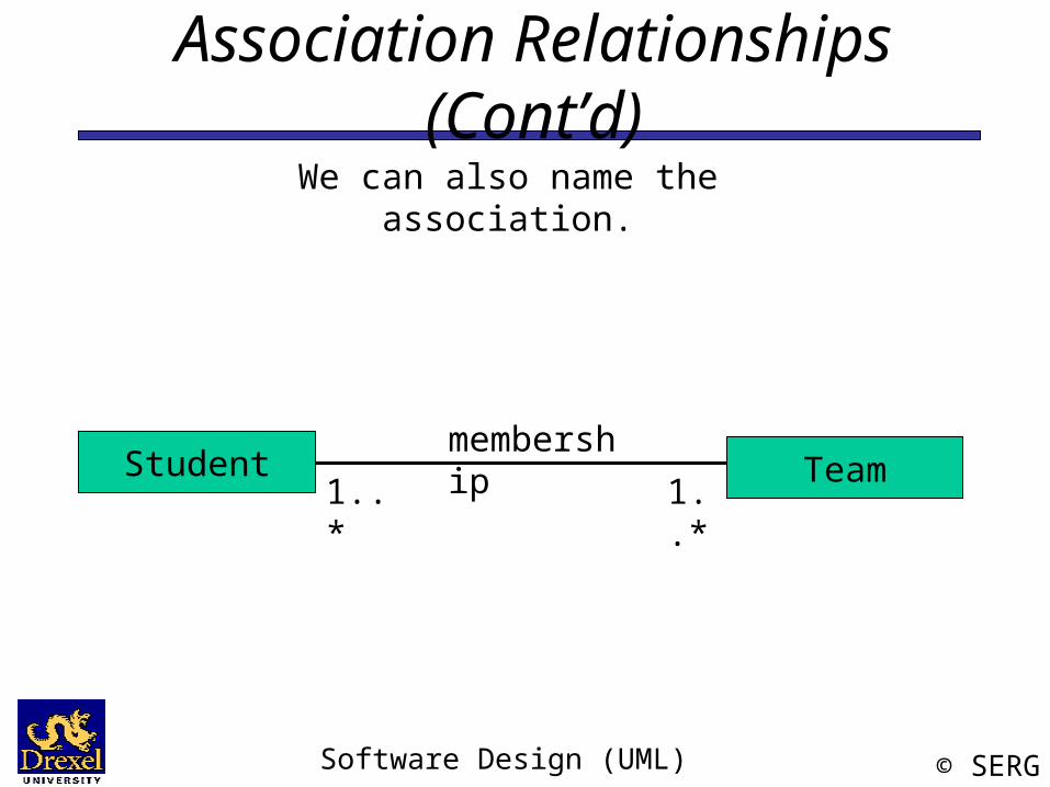
Association Relationships (Cont’d)We can also name the association.
TeamStudentmembership
1..* 1..*
Software Design (UML) © SERG
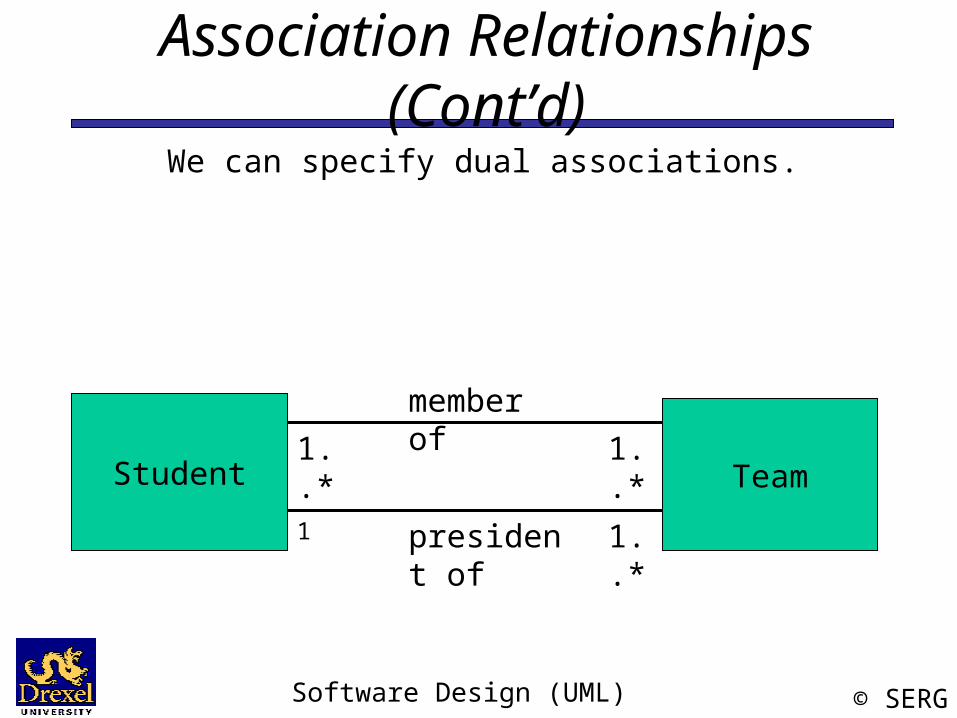
Association Relationships (Cont’d)We can specify dual associations.
TeamStudent
member of1..*
president of1 1..*
1..*
Software Design (UML) © SERG
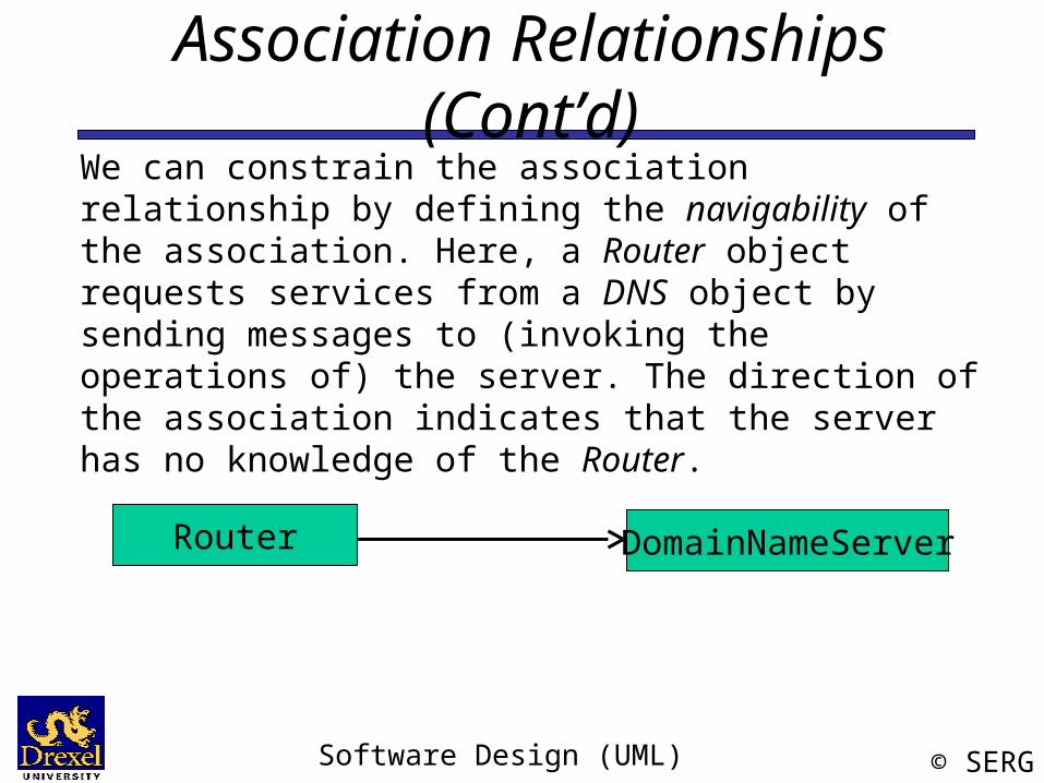
Association Relationships (Cont’d)We can constrain the association relationship by defining the navigability of the association. Here, a Router object requests services from a DNS object by sending messages to (invoking the operations of) the server. The direction of the association indicates that the server has no knowledge of the Router.
Router DomainNameServer
Software Design (UML) © SERG
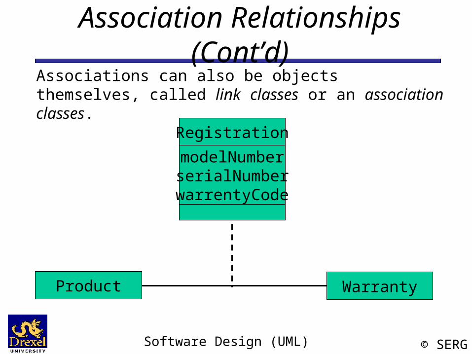
Association Relationships (Cont’d)Associations can also be objects themselves, called link classes or an association classes.
WarrantyProduct
RegistrationmodelNumberserialNumberwarrentyCode
Software Design (UML) © SERG
Association Relationships (Cont’d)
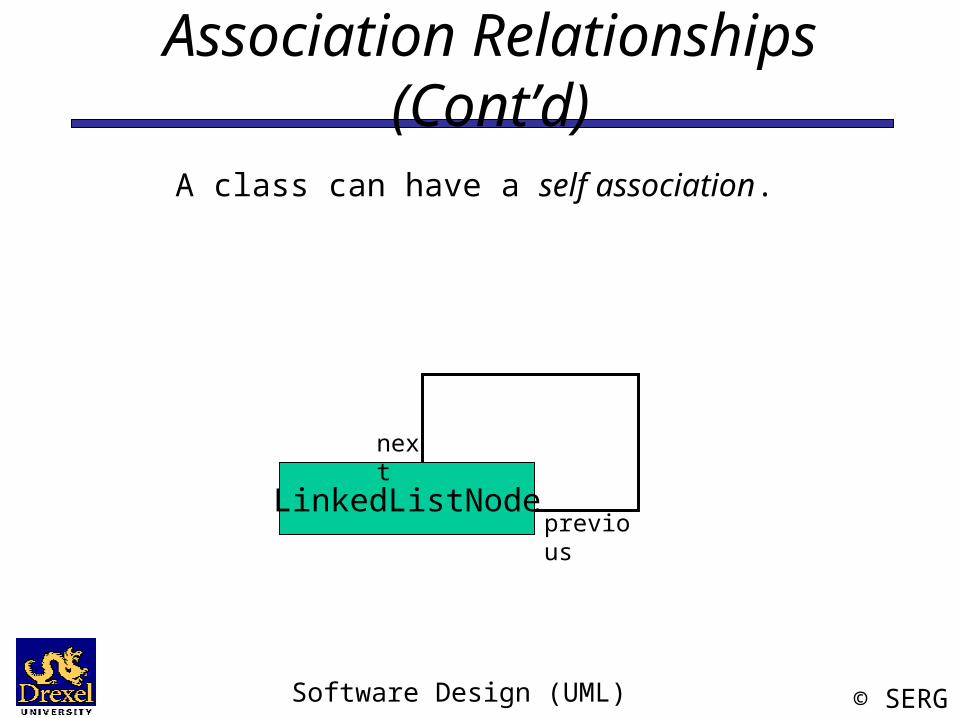
A class can have a self association.
LinkedListNode
next
previous
Software Design (UML) © SERG
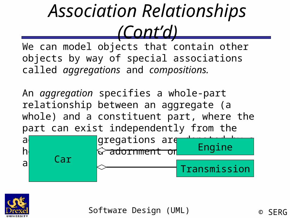
Association Relationships (Cont’d)We can model objects that contain other objects by way of special associations called aggregations and compositions.
An aggregation specifies a whole-part relationship between an aggregate (a whole) and a constituent part, where the part can exist independently from the aggregate. Aggregations are denoted by a hollow-diamond adornment on the association.
CarEngine
Transmission
Software Design (UML) © SERG
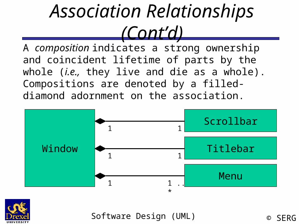
Association Relationships (Cont’d)A composition indicates a strong ownership and coincident lifetime of parts by the whole (i.e., they live and die as a whole). Compositions are denoted by a filled-diamond adornment on the association.
Window
Scrollbar
Titlebar
Menu
1
1
1
1
1
1 .. *
Software Design (UML) © SERG
Interfaces
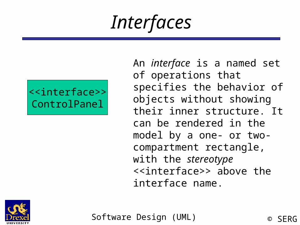
An interface is a named set of operations that specifies the behavior of objects without showing their inner structure. It can be rendered in the model by a one- or two-compartment rectangle, with the stereotype <<interface>> above the interface name.
<<interface>>ControlPanel
Software Design (UML) © SERG
Interface Services
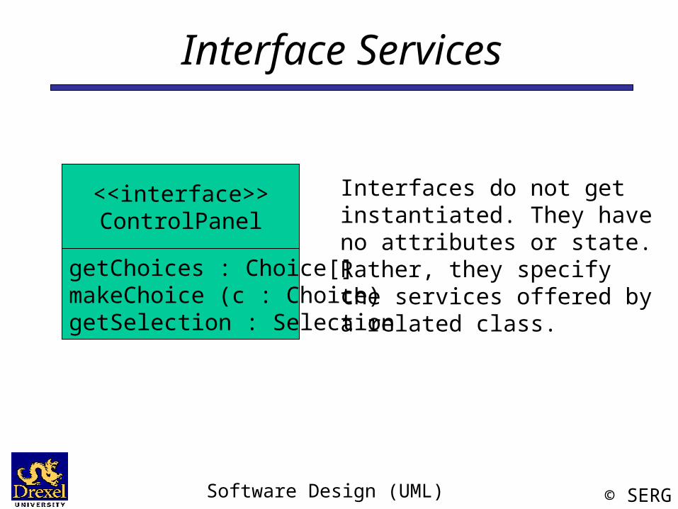
Interfaces do not get instantiated. They have no attributes or state. Rather, they specify the services offered by a related class.
<<interface>>ControlPanel
getChoices : Choice[]makeChoice (c : Choice)getSelection : Selection
Software Design (UML) © SERG
Interface Realization Relationship
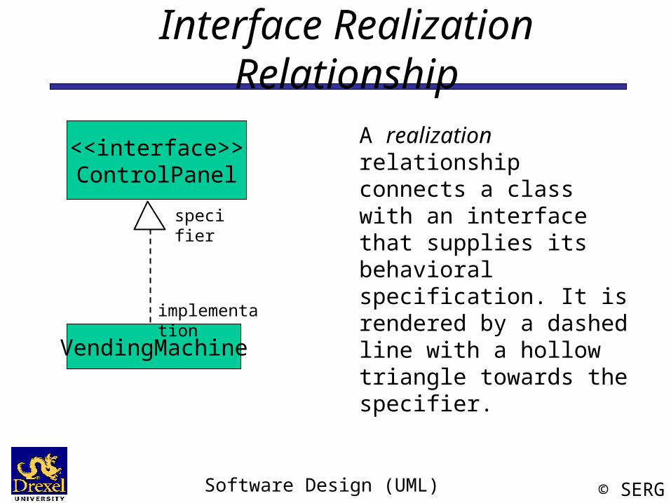
<<interface>>ControlPanel
VendingMachine
A realization relationship connects a class with an interface that supplies its behavioral specification. It is rendered by a dashed line with a hollow triangle towards the specifier.
specifier
implementation
Software Design (UML) © SERG
Interfaces
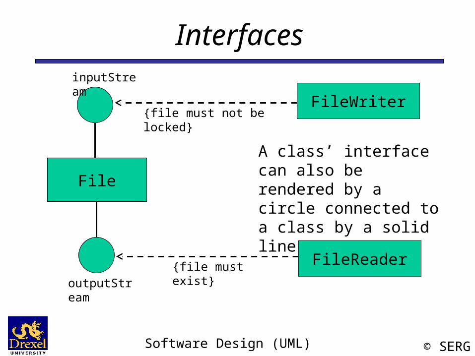
A class’ interface can also be rendered by a circle connected to a class by a solid line.
File
outputStream
inputStream
FileWriter{file must not be locked}
FileReader{file must exist}
Software Design (UML) © SERG
Parameterized Class
LinkedListT
T1 .. *
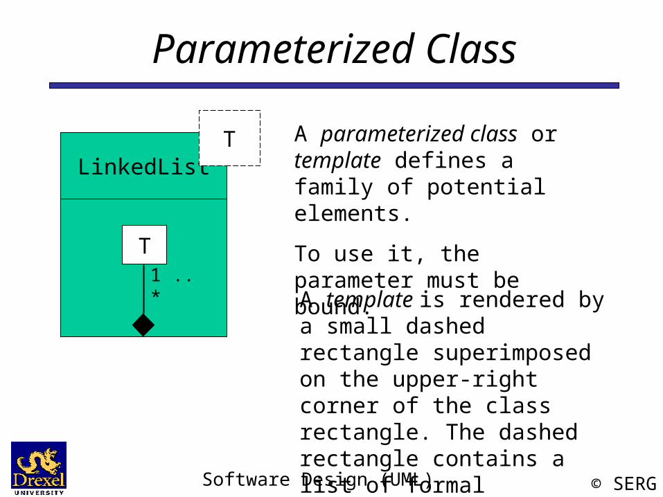
A parameterized class or template defines a family of potential elements.
To use it, the parameter must be bound.
A template is rendered by a small dashed rectangle superimposed on the upper-right corner of the class rectangle. The dashed rectangle contains a list of formal parameters for the class.
Software Design (UML) © SERG
Parameterized Class (Cont’d)
LinkedListT
T1..*
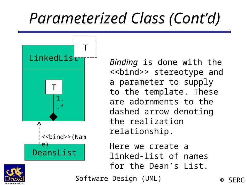
Binding is done with the <<bind>> stereotype and a parameter to supply to the template. These are adornments to the dashed arrow denoting the realization relationship.
Here we create a linked-list of names for the Dean’s List.
DeansList
<<bind>>(Name)
Software Design (UML) © SERG
Enumeration
<<enumeration>>Boolean
falsetrue
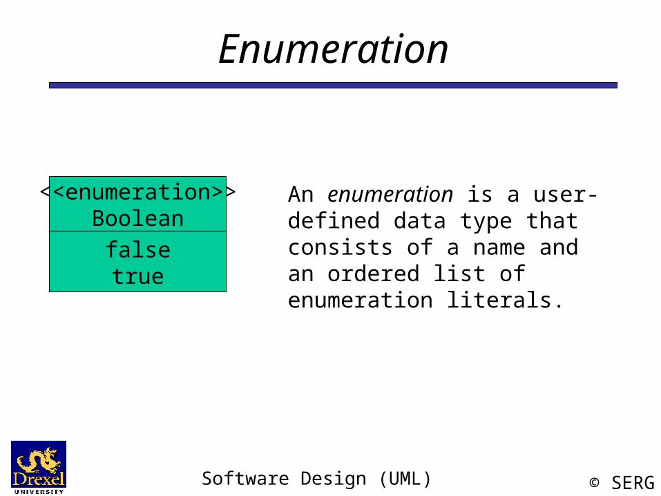
An enumeration is a user-defined data type that consists of a name and an ordered list of enumeration literals.
Software Design (UML) © SERG
Exceptions
<<exception>>KeyException
<<exception>>SQLException
<<exception>>Exception
getMessage() printStackTrace()
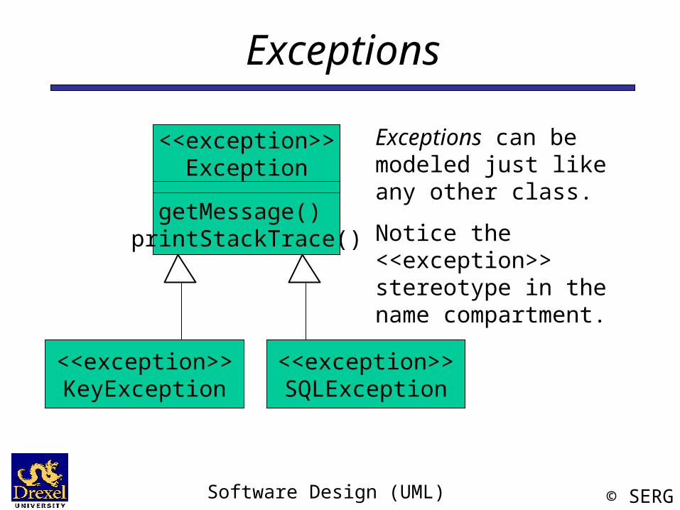
Exceptions can be modeled just like any other class.
Notice the <<exception>> stereotype in the name compartment.
Software Design (UML) © SERG
Packages
Compiler
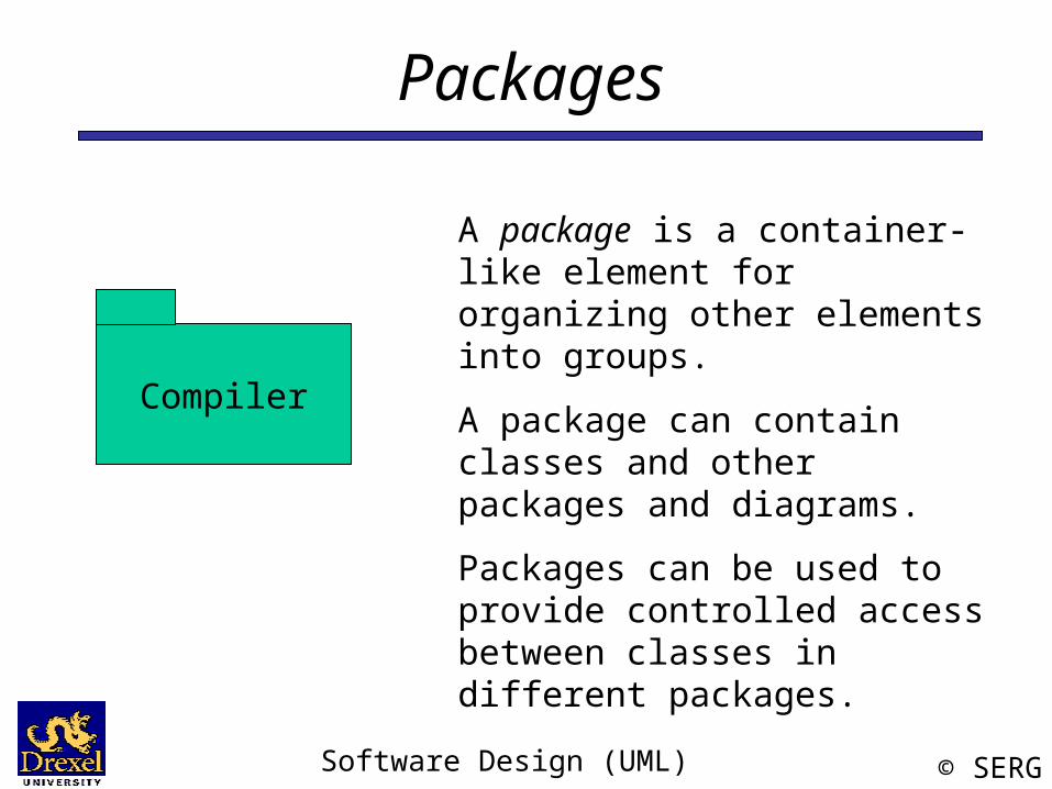
A package is a container-like element for organizing other elements into groups.
A package can contain classes and other packages and diagrams.
Packages can be used to provide controlled access between classes in different packages.
Software Design (UML) © SERG
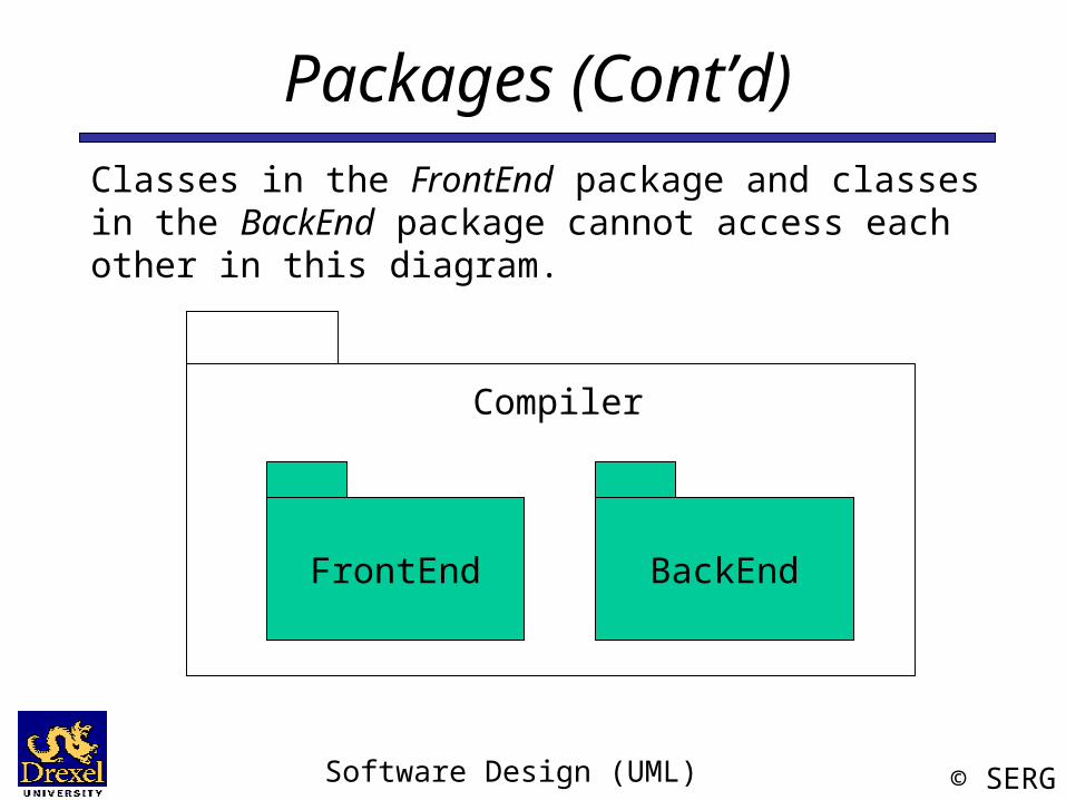
Packages (Cont’d)Classes in the FrontEnd package and classes in the BackEnd package cannot access each other in this diagram.
FrontEnd BackEnd
Compiler
Software Design (UML) © SERG
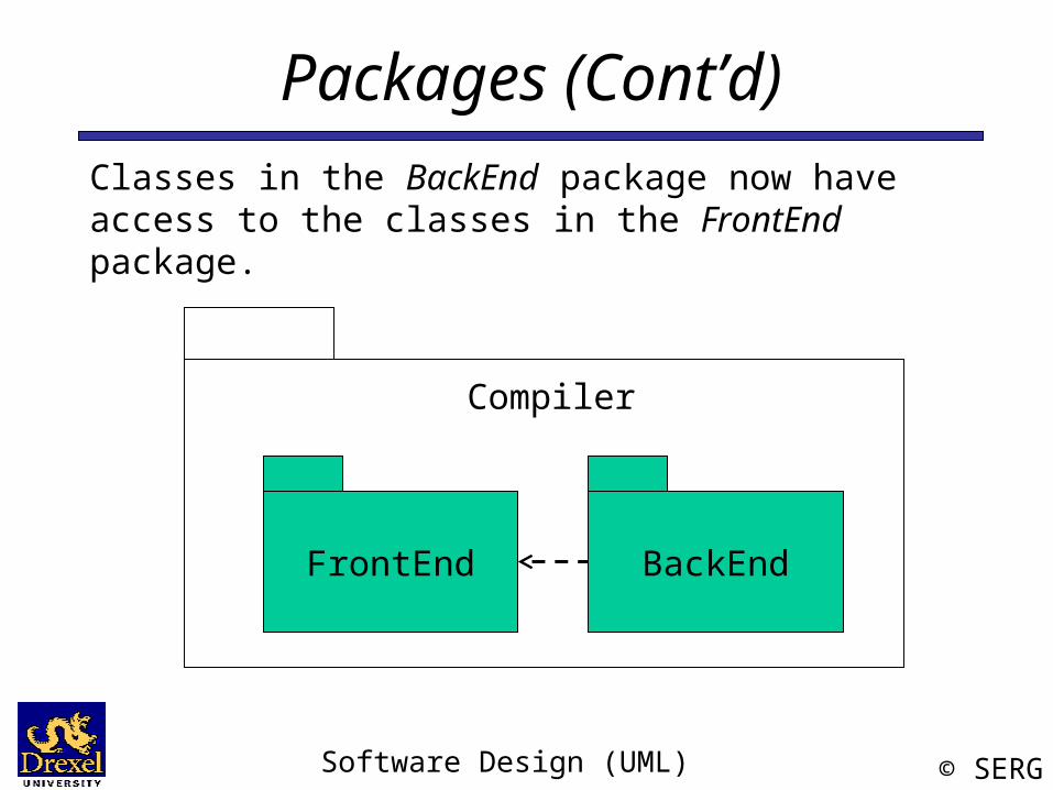
Packages (Cont’d)Classes in the BackEnd package now have access to the classes in the FrontEnd package.
FrontEnd BackEnd
Compiler
Software Design (UML) © SERG
Packages (Cont’d)
JavaCompiler
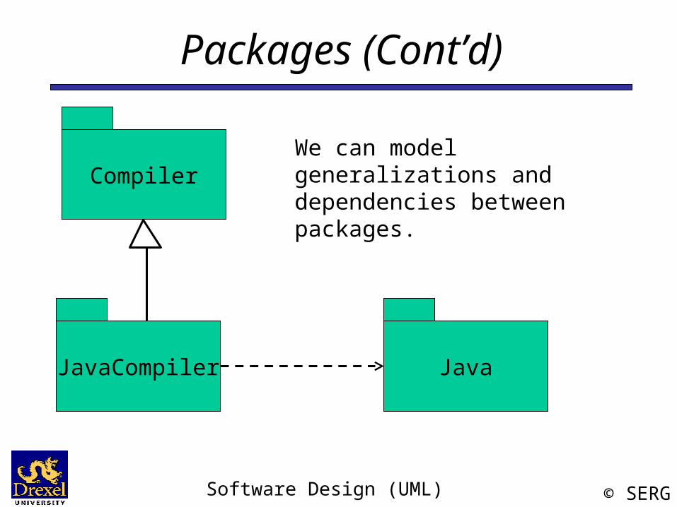
We can model generalizations and dependencies between packages.Compiler
Java
Software Design (UML) © SERG
Component DiagramComponent diagrams are one of the two kinds of diagrams found in modeling the physical aspects of an object-oriented system. They show the organization and dependencies between a set of components.
Use component diagrams to model the static implementation view of a system. This involves modeling the physical things that reside on a node, such as executables, libraries, tables, files, and documents.
- The UML User Guide, Booch et. al., 1999
Software Design (UML) © SERG
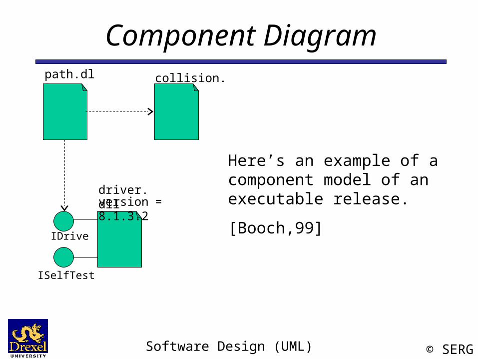
Component Diagramcollision.dll
driver.dllversion = 8.1.3.2
path.dll
IDrive
ISelfTest
Here’s an example of a component model of an executable release.
[Booch,99]
Software Design (UML) © SERG
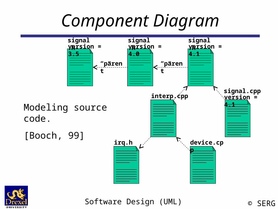
Component Diagram
“parent” “parent”
signal.hversion = 3.5
signal.hversion = 4.0
signal.hversion = 4.1
signal.cppversion = 4.1interp.cpp
irq.h device.cpp
Modeling source code.
[Booch, 99]
Software Design (UML) © SERG
Deployment DiagramDeployment diagrams are one of the two kinds of diagrams found in modeling the physical aspects of an object-oriented system. They show the configuration of run-time processing nodes and the components that live on them.
Use deployment diagrams to model the static deployment view of a system. This involves modeling the topology of the hardware on which the system executes.
- The UML User Guide, [Booch,99]
Software Design (UML) © SERG
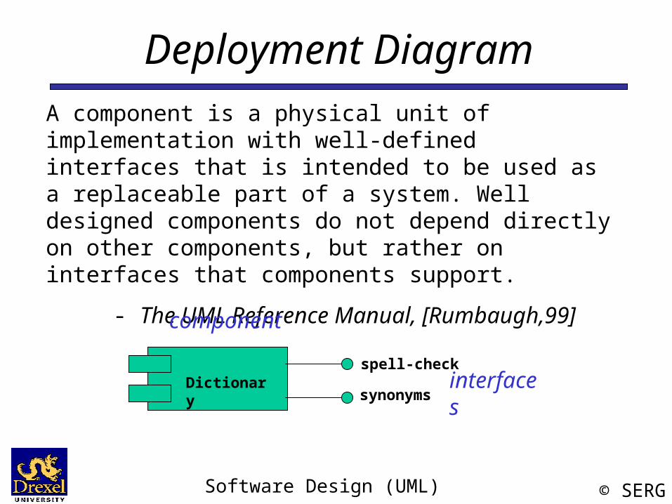
Deployment DiagramA component is a physical unit of implementation with well-defined interfaces that is intended to be used as a replaceable part of a system. Well designed components do not depend directly on other components, but rather on interfaces that components support.
- The UML Reference Manual, [Rumbaugh,99]
spell-checkDictionary
synonyms
component
interfaces
Software Design (UML) © SERG
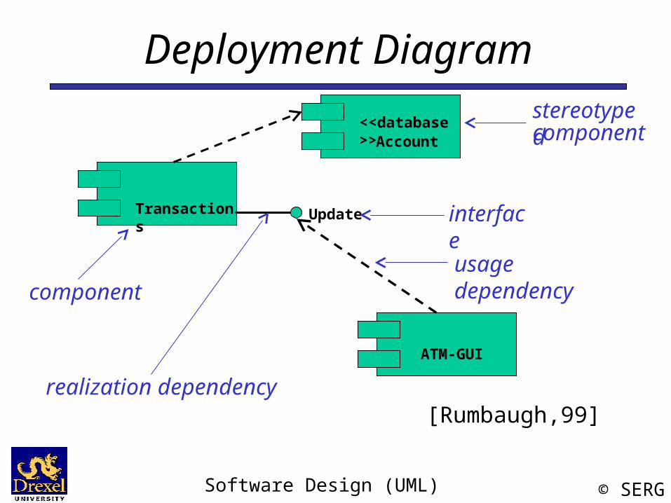
Deployment Diagram
UpdateTransactions
Account
[Rumbaugh,99]
ATM-GUI
<<database>>
component
realization dependency
interface
usage dependency
stereotypedcomponent
Software Design (UML) © SERG
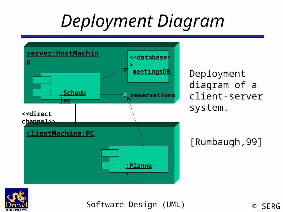
Deployment Diagram
reservations
<<database>>
meetingsDB
:Scheduler
server:HostMachine
clientMachine:PC
:Planner
Deployment diagram of a client-server system.
[Rumbaugh,99]
<<direct channel>>

Software Design (UML) © SERG
Software Design
Dynamic Modeling using the Unified Modeling Language
(UML)
Software Design (UML) © SERG
Use Case
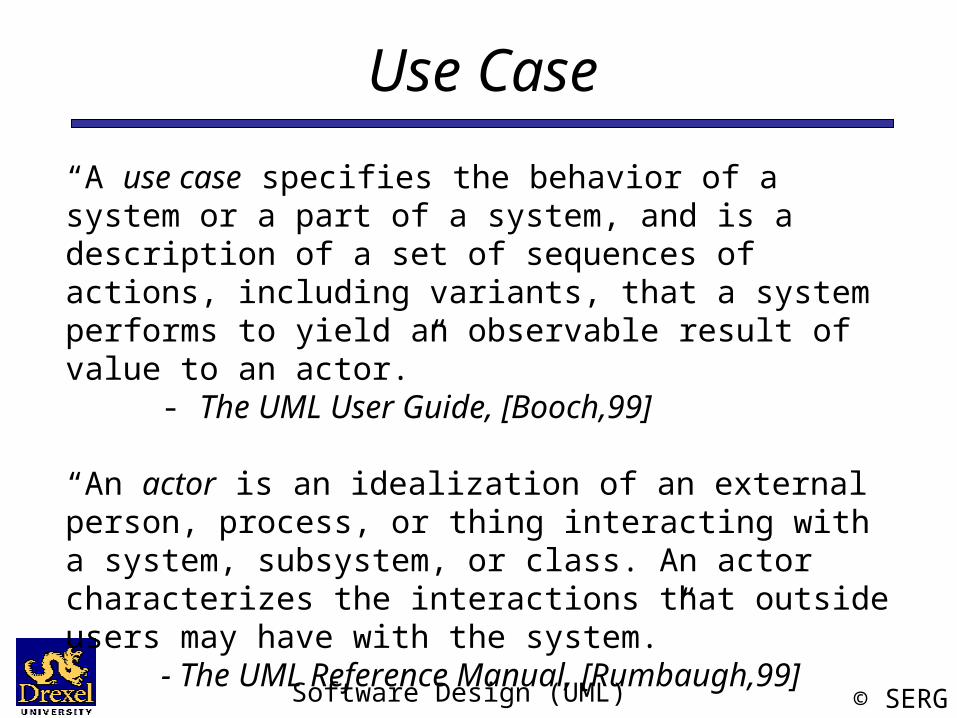
“A use case specifies the behavior of a system or a part of a system, and is a description of a set of sequences of actions, including variants, that a system performs to yield an observable result of value to an actor.”
- The UML User Guide, [Booch,99]
“An actor is an idealization of an external person, process, or thing interacting with a system, subsystem, or class. An actor characterizes the interactions that outside users may have with the system.”
- The UML Reference Manual, [Rumbaugh,99]
Software Design (UML) © SERG
Use Case (Cont’d)
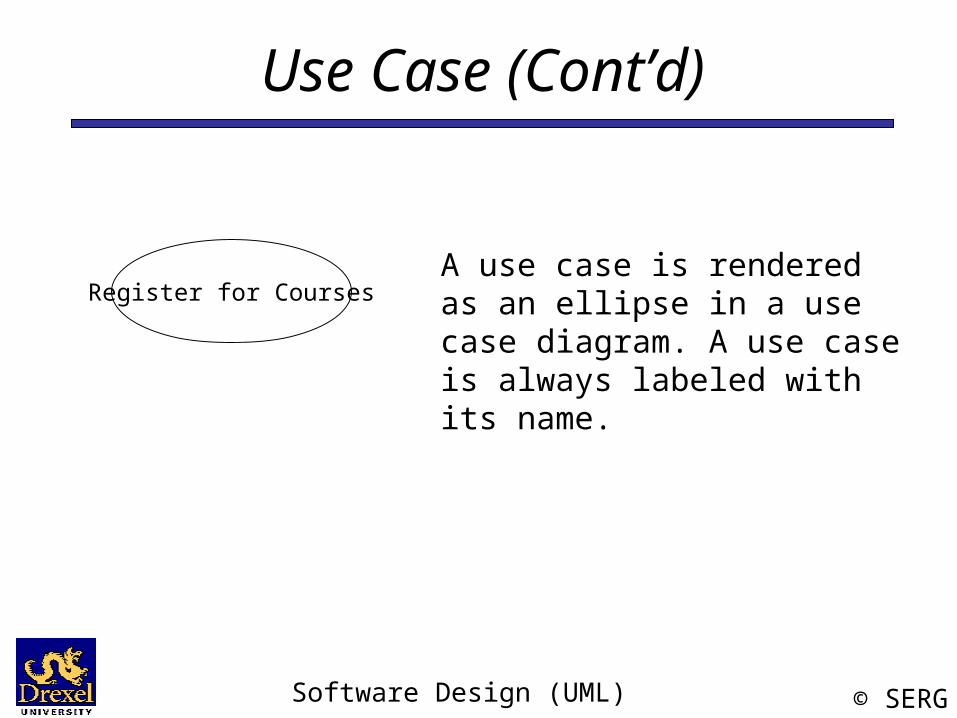
Register for CoursesA use case is rendered as an ellipse in a use case diagram. A use case is always labeled with its name.
Software Design (UML) © SERG
Use Case (Cont’d)
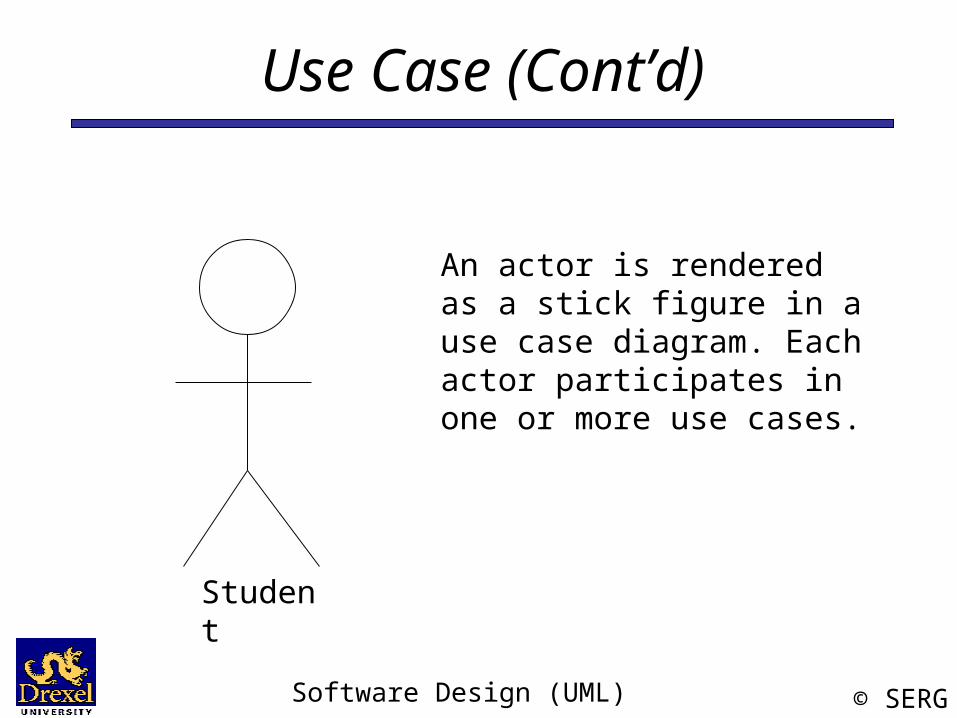
An actor is rendered as a stick figure in a use case diagram. Each actor participates in one or more use cases.
Student
Software Design (UML) © SERG
Use Case (Cont’d)
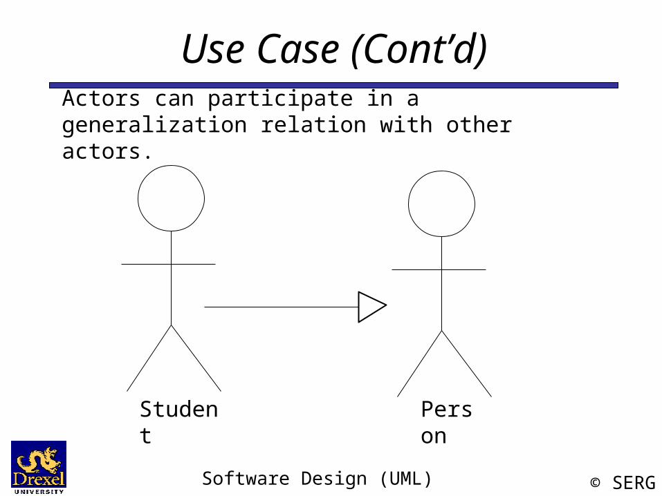
Student Person
Actors can participate in a generalization relation with other actors.
Software Design (UML) © SERG
Use Case (Cont’d)
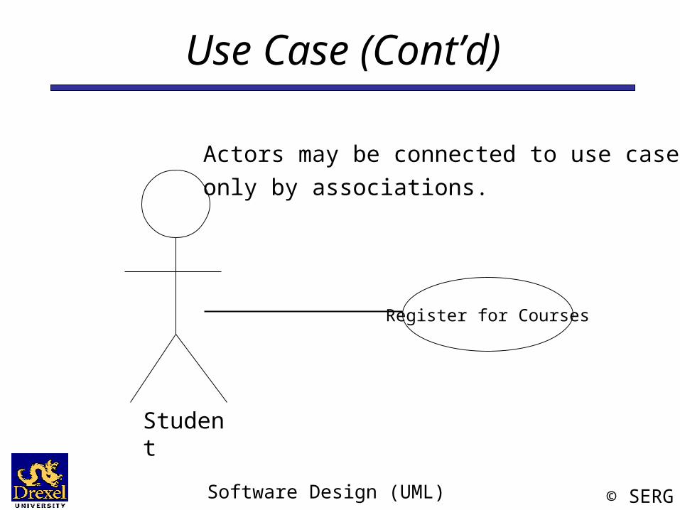
Register for Courses
Actors may be connected to use cases only by associations.
Student
Software Design (UML) © SERG
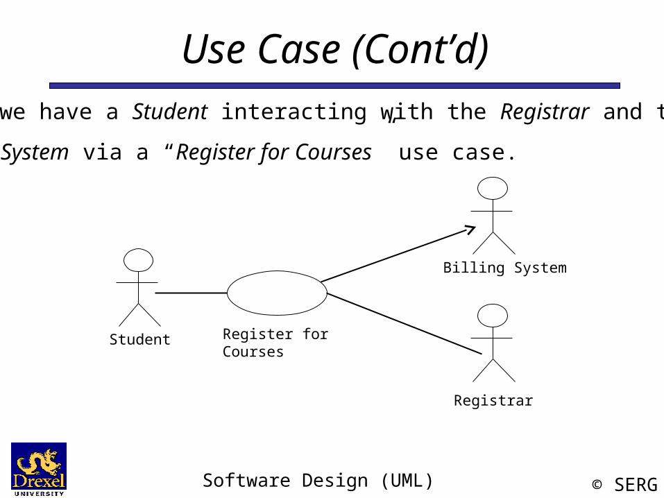
Use Case (Cont’d)
Student
Billing System
Registrar
Register for Courses
Here we have a Student interacting with the Registrar and the
Billing System via a “Register for Courses” use case.
Software Design (UML) © SERG
State Machine“The state machine view describes the dynamic behavior of objects over time by modeling the lifecycles of objects of each class. Each object is treated as an isolated entity that communicates with the rest of the world by detecting events and responding to them. Events represent the kinds of changes that objects can detect... Anything that can affect an object can be characterized as an event.”
- The UML Reference Manual, [Rumbaugh,99]
Software Design (UML) © SERG
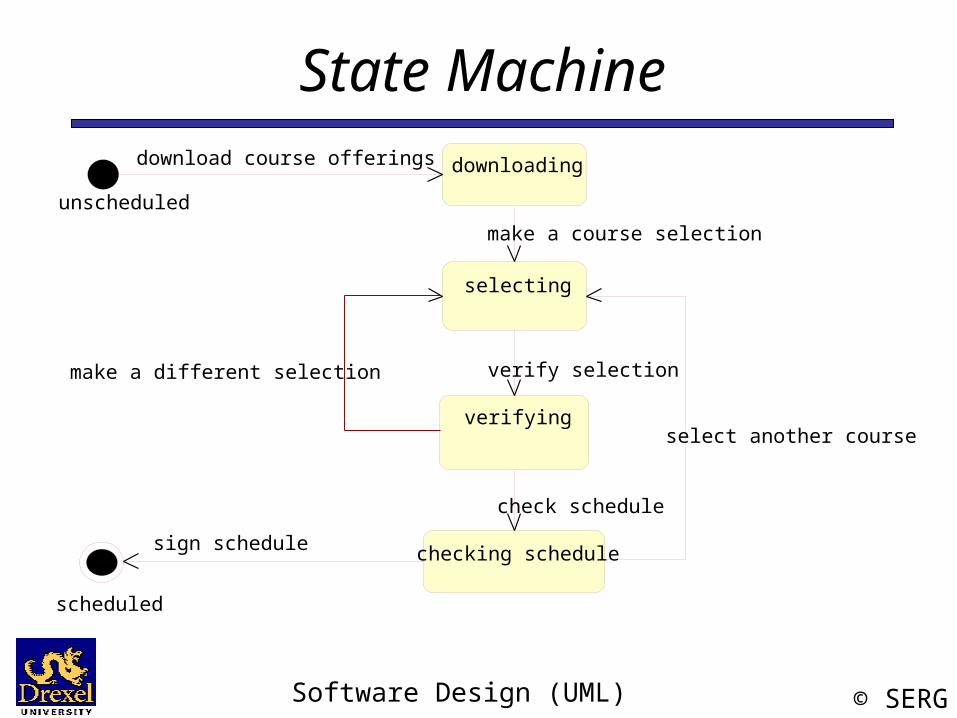
State MachineAn object must be in some specific state at any given time during its lifecycle. An object transitions from one state to another as the result of some event that affects it. You may create a state diagram for any class, collaboration, operation, or use case in a UML model .
There can be only one start state in a state diagram, but there may be many intermediate and final states.
Software Design (UML) © SERG
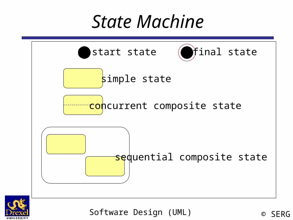
State Machinestart state final state
simple state
concurrent composite state
sequential composite state
Software Design (UML) © SERG
State Machine
selecting
verifying
downloading
checking schedule
download course offerings
make a course selection
verify selection
check schedule
select another course
make a different selection
unscheduled
scheduled
sign schedule
Software Design (UML) © SERG
Sequence DiagramA sequence diagram is an interaction diagram that emphasizes the time ordering of messages. It shows a set of objects and the messages sent and received by those objects.
Graphically, a sequence diagram is a table that shows objects arranged along the X axis and messages, ordered in increasing time, along the Y axis.
- The UML User Guide, [Booch,99]
Software Design (UML) © SERG
Sequence Diagram
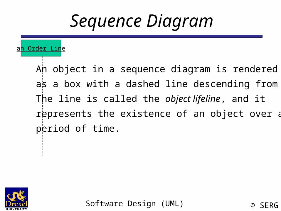
An object in a sequence diagram is renderedas a box with a dashed line descending from it.The line is called the object lifeline, and it represents the existence of an object over a period of time.
an Order Line
Software Design (UML) © SERG
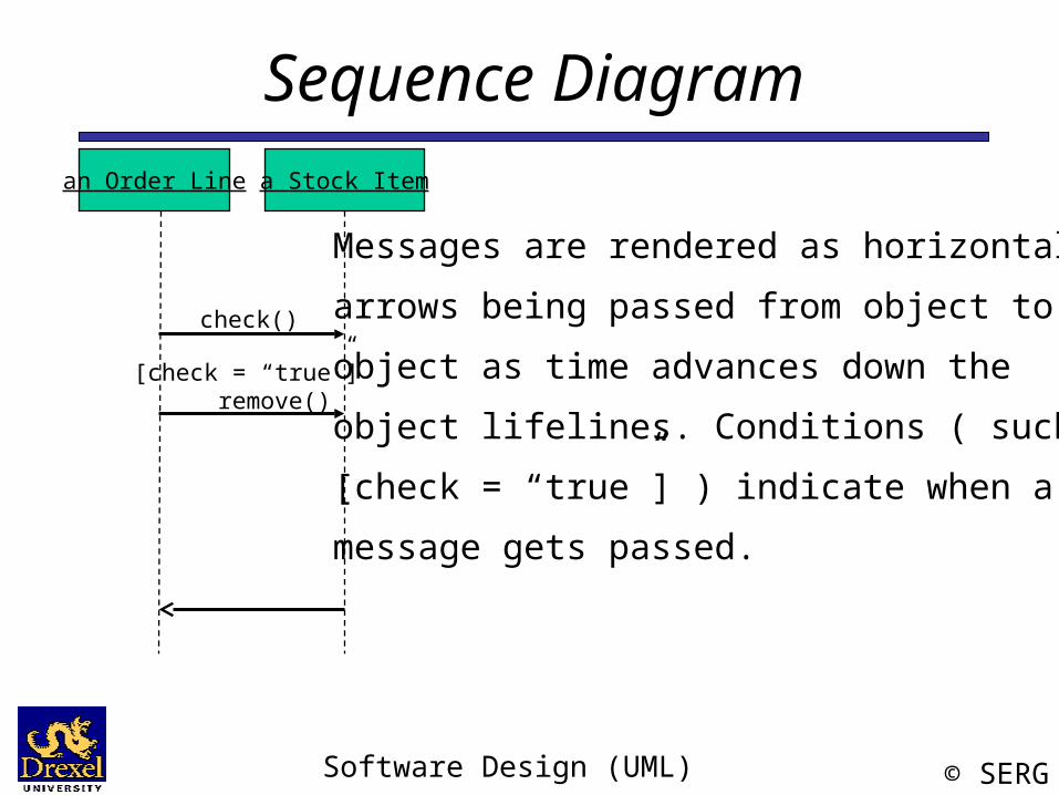
Sequence Diagraman Order Line a Stock Item
[check = “true”] remove()
check()
Messages are rendered as horizontal
arrows being passed from object to
object as time advances down the
object lifelines. Conditions ( such as
[check = “true”] ) indicate when a
message gets passed.
Software Design (UML) © SERG
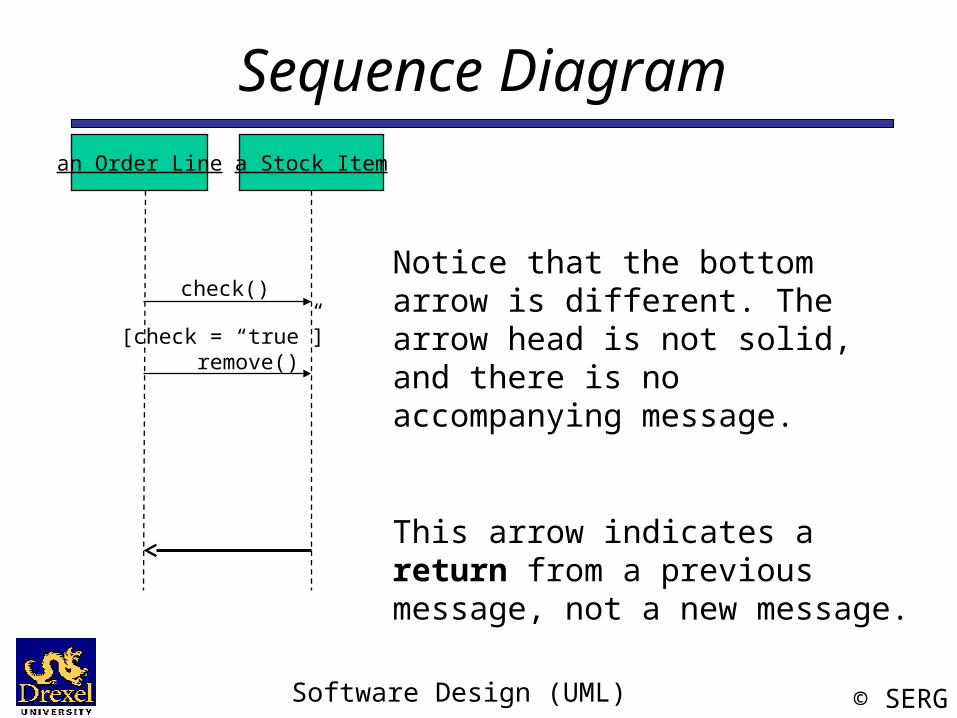
Sequence Diagraman Order Line a Stock Item
[check = “true”] remove()
check()
Notice that the bottom arrow is different. The arrow head is not solid, and there is no accompanying message.
This arrow indicates a return from a previous message, not a new message.
Software Design (UML) © SERG
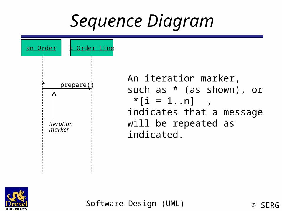
Sequence Diagraman Order a Order Line
* prepare() An iteration marker, such as * (as shown), or *[i = 1..n] , indicates that a message will be repeated as indicated.Iteration
marker
Software Design (UML) © SERG
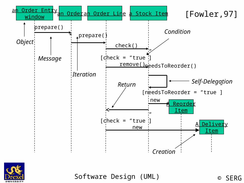
an Order Entrywindow an Order an Order Line a Stock Item
A ReorderItem
A DeliveryItem
new
[check = “true”] new
[needsToReorder = “true”]
needsToReorder()[check = “true”] remove()
check()
* prepare()prepare()
Object
Message
Iteration
Return
Creation
Condition
Self-Delegation
[Fowler,97]
Software Design (UML) © SERG
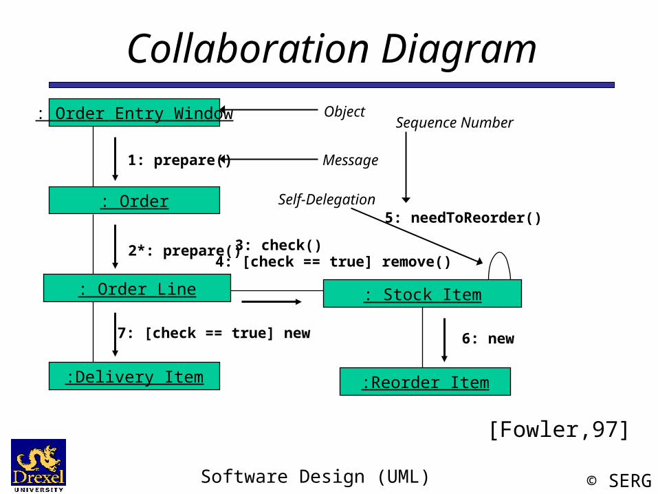
Collaboration Diagram
A collaboration diagram emphasizes the relationship of the objects that participate in an interaction. Unlike a sequence diagram, you don’t have to show the lifeline of an object explicitly in a collaboration diagram. The sequence of events are indicated by sequence numbers preceding messages.
Object identifiers are of the form objectName : className, and either the objectName or the className can be omitted, and the placement of the colon indicates either an objectName: , or a :className.
Software Design (UML) © SERG
Collaboration Diagram: Order Entry Window
: Order
: Order Line
:Delivery Item
: Stock Item
:Reorder Item
1: prepare()
2*: prepare() 3: check()4: [check == true] remove()
6: new7: [check == true] new
5: needToReorder()
[Fowler,97]
Self-Delegation
Object
Message
Sequence Number
Software Design (UML) © SERG
Collaboration DiagramSequence Diagram
Both a collaboration diagram and a sequence diagram derive from the same information in the UML’s metamodel, so you can take a diagram in one form and convert it into the other. They are semantically equivalent.
Software Design (UML) © SERG
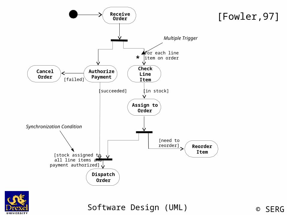
Activity DiagramAn activity diagram is essentially a flowchart, showing the flow of control from activity to activity.
Use activity diagrams to specify, construct, and document the dynamics of a society of objects, or to model the flow of control of an operation. Whereas interaction diagrams emphasize the flow of control from object to object, activity diagrams emphasize the flow of control from activity to activity. An activity is an ongoing non-atomic execution within a state machine.
- The UML User Guide, [Booch,99]
Software Design (UML) © SERG
[Fowler,97]ReceiveOrder
AuthorizePayment
CheckLineItem
CancelOrder
Assign toOrder
ReorderItem
DispatchOrder
[failed]
[succeeded] [in stock]
*for each lineitem on order
[need toreorder]
[stock assigned toall line items and
payment authorized]
Synchronization Condition
Multiple Trigger
Software Design (UML) © SERG
References[Booch99] Booch, Grady, James Rumbaugh, Ivar Jacobson,The Unified Modeling Language User Guide, Addison Wesley, 1999
[Rambaugh99] Rumbaugh, James, Ivar Jacobson, Grady Booch, The Unified
Modeling Language Reference Manual, Addison Wesley, 1999
[Jacobson99] Jacobson, Ivar, Grady Booch, James Rumbaugh, The UnifiedSoftware Development Process, Addison Wesley, 1999
[Fowler, 1997] Fowler, Martin, Kendall Scott, UML Distilled(Applying the Standard Object Modeling Language), Addison Wesley, 1997.
[Brown99] First draft of these slides were created by James Brown.