Embed Size (px)
Citation preview


Classic Instruments, Inc.
INSTALLATION MANUALFor Classic Instruments and Sending Units
❏ Instrument Adjustment❏ Troubleshooting Guide
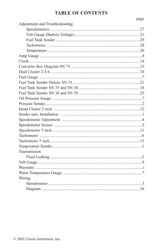
TABLE OF CONTENTSpage
Adjustment and TroubleshootingSpeedometers ........................................................................................27Volt Gauge (Battery Voltage) ................................................................31Fuel Tank Sender ..................................................................................29Tachometer ............................................................................................28Temperature ..........................................................................................30
Amp Gauge ....................................................................................................8Clock ............................................................................................................14Converter Box Diagram SN 75....................................................................15Dual Cluster 3-3/4 ........................................................................................10Fuel Gauge ....................................................................................................7Fuel Tank Sender Deluxe SN 33 ..................................................................21Fuel Tank Sender SN 35 and SN 38 ............................................................18Fuel Tank Sender SN 36 and SN 39 ............................................................25Oil Pressure Gauge ........................................................................................7Pressure Sender ..............................................................................................2Quad Cluster 5 inch ....................................................................................12Sender unit, Installation ................................................................................1Speedometer Adjustment ..............................................................................4Speedometer Sensor ......................................................................................2Speedometer 5 inch ......................................................................................11Tachometer ....................................................................................................6Tachometer 5 inch ........................................................................................13Temperature Sender........................................................................................1Transmission
Fluid Leaking ..........................................................................................2Volt Gauge......................................................................................................8Warranty..........................................................................................................iWater Temperature Gauge ..............................................................................7Wiring
Speedometer............................................................................................3Diagram ................................................................................................16
© 2002 Classic Instrument, Inc.
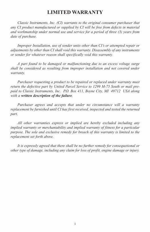
LIMITED WARRANTY
Classic Instruments, Inc. (CI) warrants to the original consumer purchaser thatany CI product manufactured or supplied by CI will be free from defects in materialand workmanship under normal use and service for a period of three (3) years fromdate of purchase.
Improper Installation, use of sender units other than CI’s or attempted repair oradjustments by other than CI shall void this warranty. Disassembly of any instrumentsor sender for whatever reason shall specifically void this warranty.
A part found to be damaged or malfunctioning due to an excess voltage surgeshall be considered as resulting from improper installation and not covered underwarranty.
Purchaser requesting a product to be repaired or replaced under warranty mustreturn the defective part by United Parcel Service to 1299 M-75 South or mail pre-paid to Classic Instruments, Inc. P.O. Box 411, Boyne City, MI 49712 USA alongwith a written description of the failure.
Purchaser agrees and accepts that under no circumstance will a warrantyreplacement be furnished until CI has first received, inspected and tested the returnedpart.
All other warranties express or implied are hereby excluded including anyimplied warranty or merchantability and implied warranty of fitness for a particularpurpose. The sole and exclusive remedy for breach of this warranty is limited to thereplacement set forth above.
It is expressly agreed that there shall be no further remedy for consequetional orother type of damage, including any claim for loss of profit, engine damage or injury.
i
Welcome to the Team of Classic Instruments!
Our congratulations and appreciation for your purchase of one of the finest qual-ity sets of specialty instruments ever produced! Your instrument set has been con-ceived, designed and manufactured by Classic Instruments, Inc. in the U.S.A. Eachinstrument has been tested and certified for accuracy and quality before packagingand shipping.
For trouble-free installation and operation follow the instructions exactly as out-lined. Your instruments were assembled to precise specifications and although eachhas a three (3) year warranty covering defective parts or workmanship - this warran-ty will not cover instruments or sender units which have been installed incorrectly.
Follow our recommended procedures for installation and proper hookup to main-tain the value and appearance of your instrument set during many future years ofaccurate and dependable service!
INSTALLING THE SENDER UNITS
1) Install the sending units provided with your set only when the engine is cold!2) ALWAYS disconnect the battery before making any electrical connections.
TEMPERATURE SENDER (Part No. SN 22, 23, 24 & 25)
Install our sender in the intake manifold near the thermostat housing. Locate apipe-thread opening in the manifold that has threads to match the sender. Be certainthe internal threads are clean and free of obstructions before installing the sender.
DO NOT use Teflon sealing tape or Gasket Cement on the threads. These mate-rials only interfere with proper electrical contacts and the heat dispersion your Classicsender is designed to operate with. The sender threads are tapered and self-sealing.The sender should be tightened only enough to prevent coolant leaking. DO NOTover tighten!
WARNING! Avoid installing our temperature senders into the head of a late-model GMC engine - even though the stock GMC sender may have been installedthere! This opening is too close to the exhaust header and will probably cause an over-heating indication on the gauge.
This can occur whenever airflow in the engine compartment slows - such as at astop street or in city traffic. A reading of from 20 - 40 degrees over the “correct”temperature can easily show on the dial-face.
1
PRESSURE SENDER(Part No. SN 52, 53, 54, 55)
GMC Installations: The correct location on most GMC V8-engines to install thePressure Sender is under the distributor housing at the rear of the block!
Use the Brass Bushing Kit (two pieces) provided to allow the Sender to bemounted at a 45-degree angle pointing towards the driver’s knees. This allows theSender to clear the back of the intake manifold, the underside of the distributor hous-ing and also the firewall.
GMC Installations - Big Block engines: We do NOT recommend installing ourPressure Sender in the opening located just above the oil filter on some big block GMengines. This location may NOT be a full-pressure passage but instead a “by-pass”oil passageway. Installing our pressure sender at this location may result in somestrange “low-pressure” readings under certain driving conditions. This does not indi-cate a defective instrument or sender! It simply means the sensor is in a location notrecommended.
Ford Installations: Install in a Ford V8 engine using the Brass Bushing Kit (all threepieces) provided. These bushings allow the Pressure Sender to be installed betweenthe motor mount and stock fuel pump. Ford also manufactures it’s own PressureSender Extension and if your engine has one of these in place, our Brass Bushing Kitwill not be required.
SPEEDOMETER SENSOR(PART No. SN 96)
GMC Installations: Our Pulse Signal Sensor has been furnished with a 7/8”-18threaded Hard-Coupler attached which threads onto the cable take-off of most GMPowerglide, Turbo 350/400 and some 700-R transmissions. NOTE: This same thread-ed Hard-Coupler will fit many early Fords (1932-48) having an enclosed torque-tubedrive line.
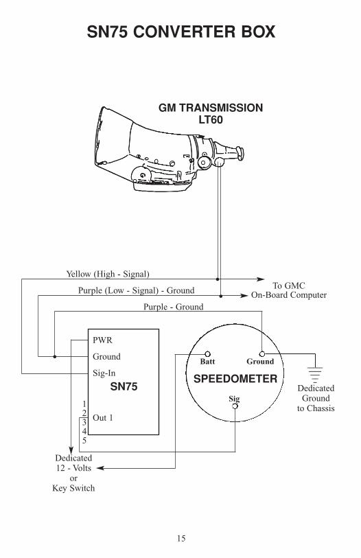
GMC Over-drive Transmissions: Refer to the specific instructions sheet packagedwith the correct Classic Converter Box Part No. Sn 75 if you are attempting to use ourspeedometer with a stock GMC speed sensor that has been factory-installed on thetransmission by GMC.
LEAKING TRANSMISSION FLUID
GMC Turbo 350 or 400: If Automatic Transmission Fluid appears to be leakingfrom “inside” our Pulse Signal Generator - a missing or broken GMC seal inside thethreaded GM-Cable/Gear Plug is most likely the cause!
2

Leaking Transmission Fluid - continued:
The most common seal used is GM Turbo 350 or 400 transmissions is GM PartNumber 1240382 or TR-1196792. This seal is a GMC and must be purchased fromeither your GMC dealer or local auto part store. Auto Transmission Fluid leakingfrom inside your Pulse Signal Generator is NOT an indication the Pulse SignalGenerator is defective.
Ford Installations: For the Ford drive-train application we have furnished a FordHard-Coupler (Part No. SN 95). This Hard-Coupler will fit most C4 Automatics or4-speed manual transmissions from Ford Motor Company.
Before installing the Ford Hard-Coupler into the transmission, transfer theoriginal plastic gear and spring-steal retaining clip from the bottom end of youroriginal Ford speedometer cable to the lower end of your Hard-Coupler. Installing theFord Hard-Coupler into the transmission will be just the opposite of the removalsequence of the stock Ford cable.
VW Installations: Install end of 48” cable (Square metal shaft) on drivers frontwheel in the square hole on dust cap using an E-Clip.
WIRING YOUR INSTRUMENTS
Follow your instructions to guarantee trouble-free installation and correctoperation! Our installation instructions and procedures should take priority overinstructions furnished by any other manufacturer of ignition systems, wiringharnesses, gauges, etc.
SPEEDOMETER(Part no. SN 83)
STEP 1: Plug the furnished Twin-Wire Lead (Part no. SN 83) into the matchingweatherproof socket of the Pulse Signal Generator on the transmission.
IMPORTANT: DO NOT substitute another brand or type of molded male-female plug socket! Use ONLY the Twin Wire-Lead furnished by “ClassicInstrument” to avoid future electrical continuity problems! Dielectric grease maybe used if pluging is too tight.
STEP 2: Twist the Twin Wire-Leads one around the other to make a “twisted pair”.Braiding or twisting these two insulated wires (one twist each 3/4”) eliminate mostoutside interference that could cause the speedometer to read incorrectly. Twin wireleads may be cut to the proper length for your particular application.
3
Speedometer - continued:
STEP 3: Route these Twin Wire-Leads separate and apart from the rest of yourwiring harness to the back of the speedometer case. DO NOT tie-wrap or run theseTwin Wire-Leads parallel or with another wiring harness.
STEP 4: Connect one of the two leads (it does not matter which) of your Twin-WireLead Kit to the terminal on the Speedometer marked “SIG”.Speedometer - continued:
STEP 5: Connect the second lead of the Twin-Wire Lead pair to the terminal post onthe speedometer marked “GND”!
STEP 6: Connect another wire (16 AWG) to the terminal post-marked “GND”(same post you connected to in step 5) and connect the other end to “chassis ground”.
IMPORTANT: DO NOT connect this second wire to any other gauge or to acommon ground connection behind the dash!
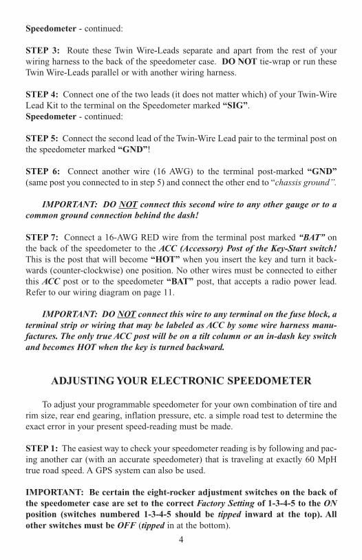
STEP 7: Connect a 16-AWG RED wire from the terminal post marked “BAT” onthe back of the speedometer to the ACC (Accessory) Post of the Key-Start switch!This is the post that will become “HOT” when you insert the key and turn it back-wards (counter-clockwise) one position. No other wires must be connected to eitherthis ACC post or to the speedometer “BAT” post, that accepts a radio power lead.Refer to our wiring diagram on page 11.
IMPORTANT: DO NOT connect this wire to any terminal on the fuse block, aterminal strip or wiring that may be labeled as ACC by some wire harness manu-factures. The only true ACC post will be on a tilt column or an in-dash key switchand becomes HOT when the key is turned backward.
ADJUSTING YOUR ELECTRONIC SPEEDOMETER
To adjust your programmable speedometer for your own combination of tire andrim size, rear end gearing, inflation pressure, etc. a simple road test to determine theexact error in your present speed-reading must be made.
STEP 1: The easiest way to check your speedometer reading is by following and pac-ing another car (with an accurate speedometer) that is traveling at exactly 60 MpHtrue road speed. A GPS system can also be used.
IMPORTANT: Be certain the eight-rocker adjustment switches on the back ofthe speedometer case are set to the correct Factory Setting of 1-3-4-5 to the ONposition (switches numbered 1-3-4-5 should be tipped inward at the top). Allother switches must be OFF (tipped in at the bottom).
4
Adjusting Your Electronic Speedometer - continued:
STEP 2: Now determine the speed-reading of your Classic speedometer when youare moving exactly 60 MpH road speed by following a pace car or by the reading ofa GPS system.
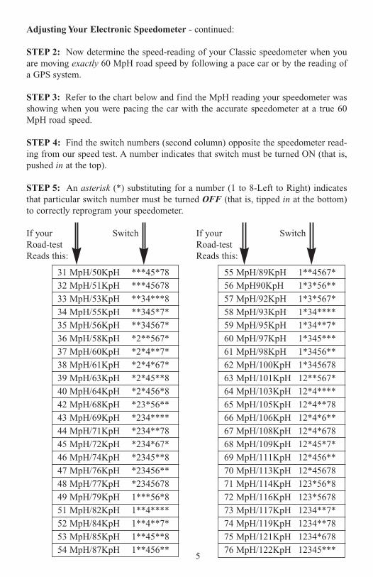
STEP 3: Refer to the chart below and find the MpH reading your speedometer wasshowing when you were pacing the car with the accurate speedometer at a true 60MpH road speed.
STEP 4: Find the switch numbers (second column) opposite the speedometer read-ing from our speed test. A number indicates that switch must be turned ON (that is,pushed in at the top).
STEP 5: An asterisk (*) substituting for a number (1 to 8-Left to Right) indicatesthat particular switch number must be turned OFF (that is, tipped in at the bottom)to correctly reprogram your speedometer.
If your Switch If your SwitchRoad-test Road-testReads this: Reads this:
5
31 MpH/50KpH ***45*78
32 MpH/51KpH ***45678
33 MpH/53KpH **34***8
34 MpH/55KpH **345*7*
35 MpH/56KpH **34567*
36 MpH/58KpH *2**567*
37 MpH/60KpH *2*4**7*
38 MpH/61KpH *2*4*67*
39 MpH/63KpH *2*45**8
40 MpH/64KpH *2*456*8
42 MpH/68KpH *23*56**
43 MpH/69KpH *234****
44 MpH/71KpH *234**78
45 MpH/72KpH *234*67*
46 MpH/74KpH *2345**8
47 MpH/76KpH *23456**
48 MpH/77KpH *2345678
49 MpH/79KpH 1***56*8
51 MpH/82KpH 1**4****
52 MpH/84KpH 1**4**7*
53 MpH/85KpH 1**45**8
54 MpH/87KpH 1**456**
55 MpH/89KpH 1**4567*
56 MpH90KpH 1*3*56**
57 MpH/92KpH 1*3*567*
58 MpH/93KpH 1*34****
59 MpH/95KpH 1*34**7*
60 MpH/97KpH 1*345***
61 MpH/98KpH 1*3456**
62 MpH/100KpH 1*345678
63 MpH/101KpH 12**567*
64 MpH/103KpH 12*4****
65 MpH/105KpH 12*4**78
66 MpH/106KpH 12*4*6**
67 MpH/108KpH 12*4*678
68 MpH/109KpH 12*45*7*
69 MpH/111KpH 12*456**
70 MpH/113KpH 12*45678
71 MpH/114KpH 123*56*8
72 MpH/116KpH 123*5678
73 MpH/117KpH 1234**7*
74 MpH/119KpH 1234**78
75 MpH/121KpH 1234*678
76 MpH/122KpH 12345***
Adjusting Your Electronic Speedometer - continued:
STEP 6: Should you ever change tire or rim size, rear-end gearing or transmissionyou must make a brand-new road test starting again at Step 1 of this section on“Adjusting Your Electronic Speedometer”. Be certain the rocker switches are alwaysreset to the Factory Setting of 1*345*** (1, 3, 4 and 5) ON (same as 60 MpH onchart) before starting another road test.
TACHOMETER
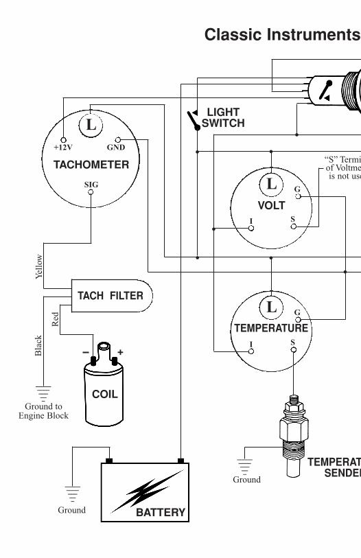
STEP 1: Locate the Tachometer Filter in your instrument set. This Filter will be aBlack plastic tube (5/8” diameter x 1” long) and have three color-coded wires (Yellow,Black and Red) protruding from one end.
STEP 2: Connect the Yellow wire of the Tach Filter to the terminal post marked“SENDER” on the back of the tachometer case.
STEP 3: Connect the Black wire of the Tach Filter to a ground point on the ENGINEblock close to the distributor! Do NOT connect this wire to “GND” on the tack or toa common-ground connection behind the dash.
STEP 4: Connect the Red wire of the Tach Filter to the correct terminal as deter-mined by the brand and type of ignition system listed below:
• Range Selector: 1=4cyl 4cycle, 2=6cyl 4cycle, 3=8cyl 4cycle.
Standard Points & Condenser system:Red wire to distributor side of coil (usually marked as “-).
GMC_HEI (High Energy Ignition system:Red wire to “TACH” terminal on coil side of distributor cap.
MSD (Multiple Spark Discharge) system:By-pass Tach Filter and connect direct to Tach Output on side of MSD box. If Tach does not respond, your MSD system may require a MSD Tach Adaptor No. 8910 or No. 8920.
Vertex Magneto systems:Red wire of Tach Filter to “Kill” terminal screw-post on side of magneto body.
Accel Ignition Coils:Red wire of Tach Filter to “Distributor” side of ignition coil.CAUTION! Some Accel ignition coils require distributor-side wire to beconnected to the “+” post on the coil and not the more-usual “-” Terminal!Read Accel instructions carefully before connecting ignition coil or filter.
6
Tachometer - continued:
Mallory Ignition System:Red wire of Tach Filter to “Distributor side of ignition coil - usually the coilterminal marked “-”. It is important to note that Mallory systems may require the Tach Selector switch to be set to the 4-cylinder setting (rather than the 8-cylinder setting) before the Tach will read correctly.
STEP 5: Connect a 16-AWG wire from the GND terminal on the back of theTachometer case to a good ground point behind the dash panel.Tachometer - continued:
STEP 6: Connect a 16-AWG wire from the Tachometer terminal post marked BATto a + 12 Volt source (terminal strip of fuse block) behind the dash panel.
FUEL GAUGE
STEP 1: Connect the first wire between the top terminal screw of the Fuel TankSender and the “S” post on the back of the fuel gauge.
STEP 2: Connect the second wire from the terminal post marked “G” on the gaugeto the “GND” post on the back of the Tachometer or to a common grounding termi-nal behind the dash panel.
STEP 3: Connect a third wire from the terminal post of the gauge marked “I” to the“BAT” post of the Tachometer. This connection should become “HOT” when the keyis turned “ON”.
WATER TEMPERATURE GAUGE
STEP 1: Install the Water Temperature Sender following the step-by-step instruc-tions outlined in the first section of this booklet.
STEP 2: Connect the first wire between the top terminal screw of the WaterTemperature Sender and the “S” post on the back of the Water Temperature Gauge.
STEP 3: Connect the second wire from the terminal post marked “G” post on theback of the Fuel Gauge. This wire may also be connected to a common groundterminal behind the dash panel.
STEP 4: Connect the last wire from the terminal post of the gauge marked “I” toeither the “I” post on the back of the Fuel Gauge or to a fuse terminal behind the dashboard. This third wire will be “HOT” when the key is turned “ON”.
7
OIL PRESSURE GAUGE
STEP 1: Install the Oil Pressure Sender provided following the step-by-step instruc-tions described at the beginning of this booklet.
STEP 2: Connect the first wire between the top terminal screw of the Oil PressureSender and the “S” post on the back of the Pressure Gauge.
STEP 3: Connect the second wire from the terminal post marked “G” on the gaugeto the “G” post on the back of the Water Temperature Gauge or you may also run thiswire to a common ground point behind the dash.
STEP 4: Connect a third wire from the terminal post of the gauge market “I” to the“I” terminal of the Water Temperature Gauge. This wire must carry + 12 Volts(“HOT”) when the key is turned “ON”.
VOLT GAUGE
STEP 1: The Volt gauge does not require a Sender and no wire should be connectedto the “S” terminal. (It is not a defect if this terminal has been cut back.)
STEP 2: Connect the first wire from the terminal post of the Volt Gauge marked “G”to the “G” post of the Oil Pressure Gauge. Connect a second wire from the sameterminal post (marked “G”) of the Volt Gauge to a good ground behind the dashboard. this wire MUST be a good ground back to the Ground-post of the battery.
STEP 3: Connect a second wire from the terminal post of the gauge marked “I” toeither a fuse terminal behind the dash or the “I” post of the Oil Pressure Gauge.Check to determine this wire will be “HOT” when the key is turned “ON”.
AMP GAUGE
The Amp gauge must be installed between the “HOT” post of the startersolenoid and the “BAT” terminal of the key switch (on the tilt-column of a in-dashkey-switch - whichever is applicable.
STEP 1: Connect a 10-AWG (minimum) Red wire from the 12-volt terminal post ofthe starter solenoid to the “I” post on the back of the gauge.
STEP 2: Connect another 10-AWG (minimum) Red wire from the “S” post of theAMP gauge to the “BAT” of the key switch (on either a tilt-column or an indash keyswitch).
STEP 3: Connect a 16-AWG or 18-AWG Black wire from the “G” post on the backof the Amp gauge to a ground connection behind the dash.
8
AMP Gauge - continued:
STEP 4: If the pointer Amp gauge reads “backwards” (indicating “discharge”) whenyou know the alternator is “charging” simply reverse the two wires connected to the“I” and “S” posts on the back of the gauge in STEP 1 and 2 above.
IMPORTANT: DO NOT allow any “ground” wire or other “ground” to contacteither the “I” or “S” terminal of Amp gauge at any time! A ground contact to eitherterminal could result in major electrical damage or fire to your wiring harness, otherelectrical components or to your vehicle.
SPECIAL INSTALLATION INSTRUCTIONS:
3-3/4” Quad-Cluster
To insure proper operation, accuracy and long-life reliability, these instructionsshould be followed step by step as outlined below.
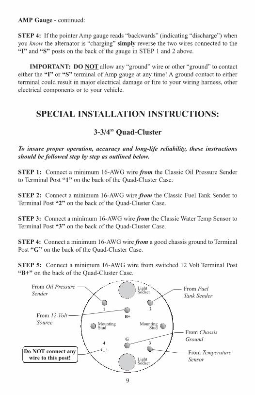
STEP 1: Connect a minimum 16-AWG wire from the Classic Oil Pressure Senderto Terminal Post “1” on the back of the Quad-Cluster Case.
STEP 2: Connect a minimum 16-AWG wire from the Classic Fuel Tank Sender toTerminal Post “2” on the back of the Quad-Cluster Case.
STEP 3: Connect a minimum 16-AWG wire from the Classic Water Temp Sensor toTerminal Post “3” on the back of the Quad-Cluster Case.
STEP 4: Connect a minimum 16-AWG wire from a good chassis ground to TerminalPost “G” on the back of the Quad-Cluster Case.
STEP 5: Connect a minimum 16-AWG wire from switched 12 Volt Terminal Post“B+” on the back of the Quad-Cluster Case.
9
LightSocket
2
G4 3
B+
1
MountingStud
MountingStud
LightSocket
From FuelTank Sender
From Oil PressureSender
From 12-VoltSource
From ChassisGround
From TemperatureSensor
Do NOT connect anywire to this post!
3-3/4” Quad-Cluster - continued:
IMPORTANT NOTICE: DO NOT connect or touch any wire to terminal post “4”on the back of the Quad-Cluster Case. This means absolutely NO hot-wire, ground,jumper, sender or otherwise should ever be connected to this post!
This terminal (number “4”) may have been deliberately removed inside the instru-ment case at our factory! This “missing” terminal screw is NOT a defect! We utilizethese circuit boards in several different configurations and “4” is not used in anyexisting automotive electrical system. Attempting to connect or touch any wire to thisterminal (“4”) can cause damage to the sensitive internal electronic circuitry. Suchdamage is not covered by warranty.
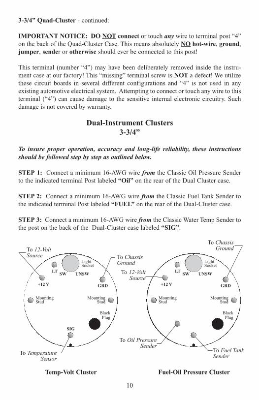
Dual-Instrument Clusters3-3/4”
To insure proper operation, accuracy and long-life reliability, these instructionsshould be followed step by step as outlined below.
STEP 1: Connect a minimum 16-AWG wire from the Classic Oil Pressure Senderto the indicated terminal Post labeled “Oil” on the rear of the Dual Cluster case.
STEP 2: Connect a minimum 16-AWG wire from the Classic Fuel Tank Sender tothe indicated terminal Post labeled “FUEL” on the rear of the Dual-Cluster case.
STEP 3: Connect a minimum 16-AWG wire from the Classic Water Temp Sender tothe post on the back of the Dual-Cluster case labeled “SIG”.
10
LightSocket
GRD
SIG
LT
+12 V
MountingStud
MountingStud
BlackPlug
To ChassisGround
To 12-VoltSource
To TemperatureSensor
To Oil PressureSender
SW UNSW
LightSocket
GRD
LT
+12 V
MountingStud
MountingStud
BlackPlug
To ChassisGround
To 12-VoltSource
To Fuel TankSender
SW UNSW
Fuel-Oil Pressure ClusterTemp-Volt Cluster
Dual-Instrument Clusters 3-3/4” - continued:
STEP 4: Connect a minimum 16-AWG wire from a good chassis ground to theTerminal Post marked as “GND” on the back of each Dual-Cluster case.
STEP 5: Connect a minimum 16-AWG wire from a switched 12 Volt source to theTerminal Post marked as “+12V” on the back of each Dual-Cluster case.
The last step is to connect a 16-AWG wire between the “LT” Terminal on the back ofeach Dual-Cluster and the dimmer-terminal post of your Headlight-Dash Lights switch.If your instrument lights remain on when your headlight switch is turned off - repositionthe Light-Socket to the “SW” instead of pointing at the “UNSW” position.
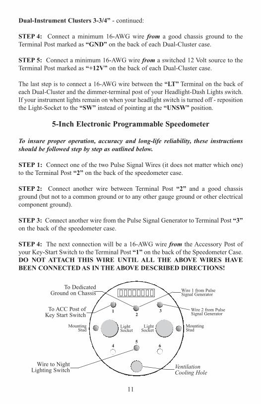
5-Inch Electronic Programmable Speedometer
To insure proper operation, accuracy and long-life reliability, these instructionsshould be followed step by step as outlined below.
STEP 1: Connect one of the two Pulse Signal Wires (it does not matter which one)to the Terminal Post “2” on the back of the speedometer case.
STEP 2: Connect another wire between Terminal Post “2” and a good chassisground (but not to a common ground or to any other gauge ground or other electricalcomponent ground).
STEP 3: Connect another wire from the Pulse Signal Generator to Terminal Post “3”on the back of the speedometer case.
STEP 4: The next connection will be a 16-AWG wire from the Accessory Post ofyour Key-Start Switch to the Terminal Post “1” on the back of the Speedometer Case.DO NOT ATTACH THIS WIRE UNTIL ALL THE ABOVE WIRES HAVEBEEN CONNECTED AS IN THE ABOVE DESCRIBED DIRECTIONS!
11
To DedicatedGround on Chassis
LightSocket
LightSocket
3
54 6
21
MountingStud
MountingStud
Wire 1 from PulseSignal Generator
VentilationCooling Hole
To ACC Post ofKey Start Switch
Wire to NightLighting Switch
Wire 2 from PulseSignal Generator
5-Inch Electronic Speedometer - continued:
STEP 5: The last step will be to connect Terminal Post “5” to your night-lighting cir-cuit or light switch.
IMPORTANT NOTICE: DO NOT connect or touch any additional wires to anyterminal posts of the speedometer. If you have used more than five wires you haveinstructions on calibrating your speedometer that should not be connected. If youhave less than five wires your speedometer will not work properly. Refer to the pre-vious instructions on calibrating your speedometer. A Calibration Chart is providedalong with instructions for making a road test.
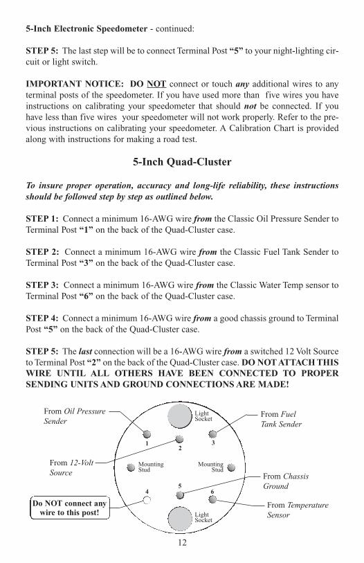
5-Inch Quad-Cluster
To insure proper operation, accuracy and long-life reliability, these instructionsshould be followed step by step as outlined below.
STEP 1: Connect a minimum 16-AWG wire from the Classic Oil Pressure Sender toTerminal Post “1” on the back of the Quad-Cluster case.
STEP 2: Connect a minimum 16-AWG wire from the Classic Fuel Tank Sender toTerminal Post “3” on the back of the Quad-Cluster case.
STEP 3: Connect a minimum 16-AWG wire from the Classic Water Temp sensor toTerminal Post “6” on the back of the Quad-Cluster case.
STEP 4: Connect a minimum 16-AWG wire from a good chassis ground to TerminalPost “5” on the back of the Quad-Cluster case.
STEP 5: The last connection will be a 16-AWG wire from a switched 12 Volt Sourceto Terminal Post “2” on the back of the Quad-Cluster case. DO NOT ATTACH THISWIRE UNTIL ALL OTHERS HAVE BEEN CONNECTED TO PROPERSENDING UNITS AND GROUND CONNECTIONS ARE MADE!
12
LightSocket
3
54 6
21
MountingStud
MountingStud
LightSocket
From FuelTank Sender
From Oil PressureSender
From 12-VoltSource From Chassis
Ground
From TemperatureSensor
Do NOT connect anywire to this post!
5-Inch Quad-Cluster - continued:
STEP 6: The last step will be to connect the light socket wires to your night-light-ing circuit of light switch. One of the two wires from each light light-socket will bethe Plus wire and the other will be the Ground wire (it does not matter which is usedfor Plus or Ground on these light leads).
IMPORTANT NOTICE: DO NOT connect or touch any wire to terminal post “4”on the back of the Quad-Cluster case. This means absolutely NO Hot-wire, Ground,Jumper, Sender or otherwise should ever be connected to this post! Attempting toconnect or touch any wire to this terminal (“4”) can cause damage to the sensitiveinternal electronic circuitry. Such damage is NOT covered by warranty (It is not adefect if this terminal has been cut back.).
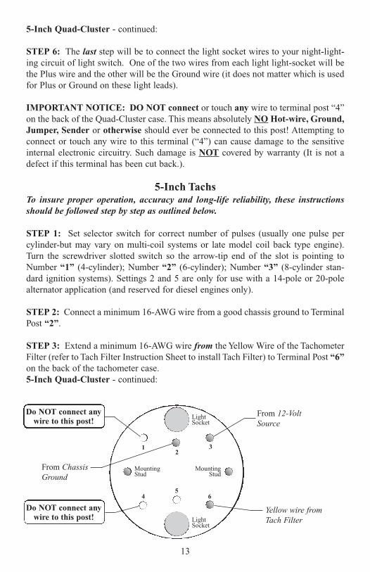
5-Inch TachsTo insure proper operation, accuracy and long-life reliability, these instructionsshould be followed step by step as outlined below.
STEP 1: Set selector switch for correct number of pulses (usually one pulse percylinder-but may vary on multi-coil systems or late model coil back type engine).Turn the screwdriver slotted switch so the arrow-tip end of the slot is pointing toNumber “1” (4-cylinder); Number “2” (6-cylinder); Number “3” (8-cylinder stan-dard ignition systems). Settings 2 and 5 are only for use with a 14-pole or 20-polealternator application (and reserved for diesel engines only).
STEP 2: Connect a minimum 16-AWG wire from a good chassis ground to TerminalPost “2”.
STEP 3: Extend a minimum 16-AWG wire from the Yellow Wire of the TachometerFilter (refer to Tach Filter Instruction Sheet to install Tach Filter) to Terminal Post “6”on the back of the tachometer case.5-Inch Quad-Cluster - continued:
13
LightSocket
3
54 6
21
MountingStud
MountingStud
LightSocket
From ChassisGround
From 12-VoltSource
Do NOT connect anywire to this post!
Do NOT connect anywire to this post!
Yellow wire fromTach Filter
5-Inch Tachs - continued:
STEP 4: The last connection will be a 16-AWG wire from a switched 12 Volt Sourceto Terminal Post “3” on the back of the Tachometer Case. DO NOT ATTACH THISWIRE UNTIL ALL OTHERS HAVE BEEN CONNECTED PROPERLY AND AGROUND CONNECTION HAS BEEN MADE.
STEP 5: The next step will be to connect the light socket wires to your night-light-ing circuit or light switch. One of the two wires from each light-socket will be thePLUS wire and the other will be the Ground wire (it does not matter which is usedfor Plus or Ground on these light leads).
IMPORTANT NOTICE: DO NOT connect or touch any posts numbered as “1”and “4” on the back of the Tachometer case. This means absolutely NO wire - HOT,Ground, Jumper, Sender or otherwise should ever be connected to either of theseposts! Connecting any wire to these posts can cause damage to the sensitive internalelectronic circuitry. Such damage is not covered by warranty.
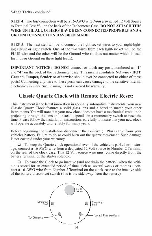
Classic Quartz Clock with Remote Electric Reset:
This instrument is the latest innovation in specialty automotive instruments. Your newClassic Quartz Clock features a solid glass lens and a bezel to match your otherinstruments. You will note that your new clock does not have a mechanical reset-knobprojecting through the lens and instead depends on a momentary switch to reset thetime. Please follow the installation instructions carefully to insure that your new clockwill operate accurately and reliably for many years.
Before beginning the installation disconnect the Positive (+ Plus) cable from yourvehicles battery. Failure to do so could burn out the quartz movement. Such damageis not covered under your warranty.
❏ To keep the Quartz clock operational even if the vehicle is parked or in stor-age: connect a 16 AWG wire from a dedicated 12 Volt source to Number 2 Terminalon the rear of the clock case. This 12 Volt source wire must come directly from thebattery terminal of the starter solenoid.
❏ To cause the Clock to go inactive (and not drain the battery) when the vehi-cle is stored for an extended period of time such as several weeks or months - con-nect a 16-AWG wire from Number 2 Terminal on the clock-case to the inactive sideof the battery disconnect switch (this is the side away from the battery).
14
LightSocket
1 2
MountingStud
MountingStud
To 12 Volt BatteryTo Ground
15
PWR
Ground
Sig-In
Out 1
GM TRANSMISSIONLT60
SN75
SN75 CONVERTER BOX
_______________DedicatedGround
to Chassis
Yellow (High - Signal)
Purple (Low - Signal) - Ground To GMC On-Board Computer
Purple - Ground
Dedicated12 - Volts
orKey Switch
SPEEDOMETER
Ground
Sig
Batt•
••
12345
LVOLT
G
SI
LTEMPERATURE
G
SI
L
TACHOMETER
GND
SIG
+12V
TACH FILTER
_______________
______________________________
+
BATTERYGround
“S” Termiof Voltmeis not use
TEMPERATSENDER
COIL
Ground
Ground toEngine Block
Bla
ck
Red
Yel
low
LIGHTSWITCH
•
••
•
••
•
Classic Instruments
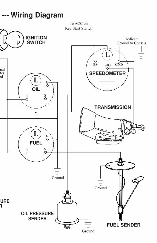
DedicateGround to Chassis
_______________
LOIL
G
SI
LFUEL
G
SI
L
SPEEDOMETER
GNDSIGB+
______________________________
_______________
TRANSMISSION
FUEL SENDER
OIL PRESSURESENDER
nal ter ed
Ground
TURER
Ground
Ground
IGNITIONSWITCH
•
••
•
--- Wiring DiagramTo ACC on
Key Start Switch
Classic Quartz Clock with Remote Electric Reset: - continued:
❏ Connect a 16-AWG wire from the Terminal Post marked “1” on the rear ofthe clock case to a good negative ground point behind the dashboard.
❏ Purchase a Push Button type switch, through Classic Instruments, Inc..Install switch under the dashboard - probably out of sight to the vehicles occupants.Connect the two wires exiting from the rear case-wall of the clock to opposite termi-nals on the momentary switch. If necessary these wires may be extended to any lengthin order to reach the switch location.
❏ Reconnect the heavy battery cable to your vehicles’ battery. The clockshould now start to run. Since we do not use second-hand - you should wait a minuteor more to determine the clock movement is running.
❏ To advance the time one minute - press the switch only once. To advancemore than a few minutes press and hold the switch until the desired time is reached.The clocks’ minute and hour hands will fast-forward. Release the switch when theclock is almost reset to the correct time. To set the time exactly the switch should bepushed only one timer per each minute you want to advance the minute hand.
Important Notice: Should either the quartz movement, internal circuitry or electroniccomponents inside your clock be damaged due to a voltage surge or the Plus and Negativewires being connected in reverse the unit will NOT be covered under warranty.
Fuel Tank Sender SN 35 and SN 38
CAUTION: DISCONNECT BATTERY CABLE BEFORE INSTALLING FUELLEVEL SENDER
STEP 1: Determine required float arm position. Senders are assembled for RightHand float swing. Do not change this position unless you contact our Tech depart-ment. Many incorrect fuel gauge readings are due to improper modificationsbeing attempted by the installer.
STEP 2: Cut a 1-5/8” diameter hole in top of the tank where sender is to be locatedover the deepest park of the tank and as close to the center of tank as possible. Be cer-tain that area where sender is to be mounted is free of obstructions of baffles that willinterfere with float.
STEP 3: Measure tank-depth vertically through the sender-mounting hole.
STEP 4: Remove RHEOSTAT HOUSING from SUPPORT ARM by removing thetwo screws. Then carefully cut the SUPPORT ARM at a point that is equal to 1/2 thetank depth + 1-5/8” - refer to Figure 2.
After removing the RHEOSTAT HOUSING from the SUPPORT ARM-slide the corkgasket (furnished) up the SUPPORT ARM towards the underside of the MountingFlange.
18
Fuel Tank Sender SN 35 and SN 38 - Continued
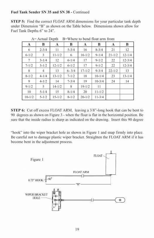
STEP 5: Find the correct FLOAT ARM dimensions for your particular tank depthunder Dimension “B” as shown on the Table below. Dimensions shown allow forFuel Tank Depths 6” to 24”.
STEP 6: Cut off excess FLOAT ARM, leaving a 3/8”-long hook that can be bent to90 degrees as shown on Figure 3 - when the float is flat in the horizontal position. Besure that the inside radius is sharp as indicated on the drawing. Insert this 90 degree
“hook” into the wiper bracket hole as shown in Figure 1 and snap firmly into place.Be careful not to damage plastic wiper bracket. Straighten the FLOAT ARM if it hasbecome bent in the adjustment process.
19
A= Actual Depth B=Where to bend float arm from
A B A B A B A B6 2-3/4 11 5-3/4 16 8-3/4 21 12
6-1/2 3 11-1/2 6 16-1/2 9-1/4 21-1/2 12-1/4
7 3-1/4 12 6-1/4 17 9-1/2 22 12-3/4
7-1/2 3-1/2 12-1/2 6-1/2 17 9-1/2 22 12-3/4
8 4 13 6- 3/4 17-1/2 9-3/4 22-1/2 13
8-1/2 4-1/4 13-1/2 7-1/2 18 10-1/4 23 13-1/4
9 4-1/2 14 7-3/4 19 10-3/4 24 14
9-1/2 5 14-1/2 8 19-1/2 11
10 5-1/4 15 8-1/4 20 11-1/2
10-1/2 5-1/2 15-1/2 8-1/2 20-1/2 11-3/4
Figure 1
Fuel Tank Sender SN 35 and SN 38 - Continued
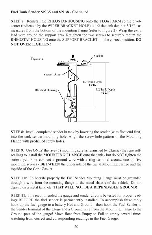
STEP 7: Reinstall the RHEOSTAT-HOUSING onto the FLOAT ARM so the pivot-center (indicated by the WIPER BRACKET HOLE) is 1/2 the tank depth + 3/16” - asmeasures from the bottom of the mounting flange (refer to Figure 2). Wrap the extralead wire around the support arm. Retighten the two screws to securely mount theRHEOSTAT HOUSING onto the SUPPORT BRACKET - in the correct position. DONOT OVER TIGHTEN!
STEP 8: Install completed sender in tank by lowering the sender (with float end first)into the tank sender-mounting hole. Align the screw-hole pattern of the MountingFlange with predrilled screw holes.
STEP 9: Use ONLY the five (5) mounting screws furnished by Classic (they are self-sealing) to install the MOUNTING FLANGE onto the tank - but do NOT tighten thescrews yet! First connect a ground wire with a ring-terminal around one of fivemounting screws - BETWEEN the underside of the metal Mounting Flange and thetopside of the Cork Gasket.
STEP 10: To operate properly the Fuel Sender Mounting Flange must be groundedthrough a wire from the mounting flange to the metal chassis of the vehicle. Do notdepend on a metal tank, etc. THAT WILL NOT BE A DEPENDABLE GROUND!
STEP 11: It is recommended the gauge and sender circuits be tested for proper read-ings BEFORE the fuel sender is permanently installed. To accomplish this-simplyhook up the fuel gauge to a battery Hot and Ground - then hook the Fuel Sender tothe Sender terminal of the gauge and a Ground wire from the Mounting Flange to theGround post of the gauge! Move float from Empty to Full to empty several timeswatching from correct and corresponding readings in the Fuel Gauge.
20
Figure 2
STAINLESS STEEL DELUXE SENDER SN33
STEP 1: Cut a 1-3/4 inch (minimum 1-11/16 inches) diameter opening through thetop part of the fuel tank. If the tank already has a smaller opening - either enlarge theexisting opening to 1-3/4 inches or file notches on the edge of opening to allow theRESISTOR-HOUSING to be slid into the tank.
STEP 2: It is recommended that this opening be located over the deepest part of thetank if possible. The opening should also be located on a flat, level area so as to avoidtank baffles or other obstructions inside the tank.
STEP 3: For best results the sender opening should be as close to the centerline ofthe car as possible. This will keep excessive fuel movement (“sloshing”) side-to-sidefrom seriously affecting the gauge reading.
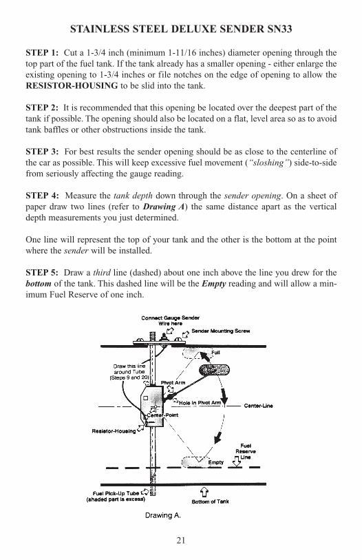
STEP 4: Measure the tank depth down through the sender opening. On a sheet ofpaper draw two lines (refer to Drawing A) the same distance apart as the verticaldepth measurements you just determined.
One line will represent the top of your tank and the other is the bottom at the pointwhere the sender will be installed.
STEP 5: Draw a third line (dashed) about one inch above the line you drew for thebottom of the tank. This dashed line will be the Empty reading and will allow a min-imum Fuel Reserve of one inch.
21
STAINLESS STEEL DELUXE SENDER SN33 - continued
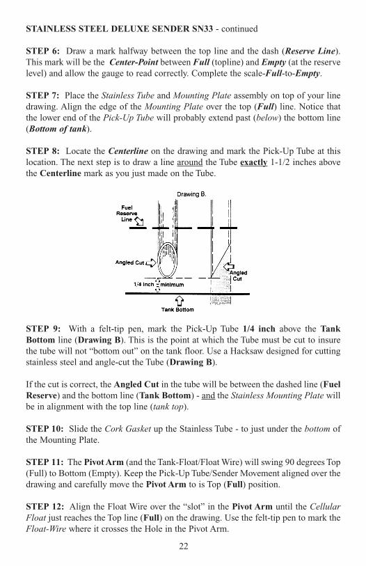
STEP 6: Draw a mark halfway between the top line and the dash (Reserve Line).This mark will be the Center-Point between Full (topline) and Empty (at the reservelevel) and allow the gauge to read correctly. Complete the scale-Full-to-Empty.
STEP 7: Place the Stainless Tube and Mounting Plate assembly on top of your linedrawing. Align the edge of the Mounting Plate over the top (Full) line. Notice thatthe lower end of the Pick-Up Tube will probably extend past (below) the bottom line(Bottom of tank).
STEP 8: Locate the Centerline on the drawing and mark the Pick-Up Tube at thislocation. The next step is to draw a line around the Tube exactly 1-1/2 inches abovethe Centerline mark as you just made on the Tube.
STEP 9: With a felt-tip pen, mark the Pick-Up Tube 1/4 inch above the TankBottom line (Drawing B). This is the point at which the Tube must be cut to insurethe tube will not “bottom out” on the tank floor. Use a Hacksaw designed for cuttingstainless steel and angle-cut the Tube (Drawing B).
If the cut is correct, the Angled Cut in the tube will be between the dashed line (FuelReserve) and the bottom line (Tank Bottom) - and the Stainless Mounting Plate willbe in alignment with the top line (tank top).
STEP 10: Slide the Cork Gasket up the Stainless Tube - to just under the bottom ofthe Mounting Plate.
STEP 11: The Pivot Arm (and the Tank-Float/Float Wire) will swing 90 degrees Top(Full) to Bottom (Empty). Keep the Pick-Up Tube/Sender Movement aligned over thedrawing and carefully move the Pivot Arm to is Top (Full) position.
STEP 12: Align the Float Wire over the “slot” in the Pivot Arm until the CellularFloat just reaches the Top line (Full) on the drawing. Use the felt-tip pen to mark theFloat-Wire where it crosses the Hole in the Pivot Arm.
22
STAINLESS STEEL DELUXE SENDER SN33 - continued
STEP 13: Remove the Float-Wire and bend carefully at this mark to a 90 degreeangle. Bend in the same direction as the bend end holding the float. Cut excessFloat -wire 1/4 inch below (away from the Float) the 90 degree bend with wire-cut-ters. This will result in the end having a 1/4 inch “hook”.
STEP 14: Insert the 1/4 inch “hook” through the Hole in the Pivot Arm and pressthe Float Wire into the “slot” of the Pivot Arm. Swing the Float downward towardsthe dotted line on the drawing. the black Cellular Float should just touch the dottedline at the same time the Pivot Arm “bottoms out” in the opening on the side of theResistor-Housing.
STEP 15: Your Fuel Sender is now set properly for your tank depth and will allow aReserve fuel supply when Empty is indicated on the gauge.
STEP 16: Firmly crimp the edges of the Pivot Arm around the Float-Wire for asecure and permanent attachment.
STEP 17: Loosen the two NO.10-32 Stainless Pan-Head Phillips 3/4-inch screws onthe Stainless-Steel U-Bracket and carefully slide the Resistor-Housing down the Tubeto the end.
Do NOT slide the Resistor-Housing Off the pickup-tube.
STEP 18: Gently tighten the screws to again temporarily hold the Resistor-Housingassembly on the lower end of the Pick-Up Tube.
STEP 19: Lower the Pivot Arm (with Float-Wire and Tank Float attached) so as topoint into the tank opening. Insert Tank-Float and Float-Wire through the openinguntil the Resistor-Housing/Pick-Up Tube assembly is just starting to enter throughthe tank opening.
STEP 20: Hold the Resistor-Housing securely and loosen the Tube from the U-Bracket by unscrewing the two screws slightly.
STEP 21: Carefully slide the Pick-Up Tube downward through the U-Bracketassembly (into the Tank) until the top of the Resistor-Housing aligns with thecircumference mark (As determined in step 8.) on the tank Tube.
STEP 22: Tighten the two stainless locking screws firmly after making certain theFloat-Arm and Resistor-Housing assembly is correctly rotated on the Tube. The rota-tion-adjustment must align the Float to point away from any baffles or other obstruc-tions.
23

STAINLESS STEEL DELUXE SENDER SN33 - continued
STEP 23: The Cork Gasket and Sender Mounting Plate can now be aligned over thetank opening and fastened securely with the five Insulated Leak-Proof Screws provided.
STEP 24: Connect a ground wire from one of five Sender Mounting Screws to themetal chassis for proper gauge operation.
NOTE: Terms of Parts in Bold type indicate parts mentioned on the drawings. Italicizedterm or parts reference parts not specifically labeled as such on the drawings
24
CLASSIC - FUEL LEVEL SENDERSN 36 and SN 38
ADJUSTABLE FOR TANK DEPTHS 6” TO 24”
CAUTION: DISCONNECT BATTERY BEFORE INSTALLING THIS SENDER!
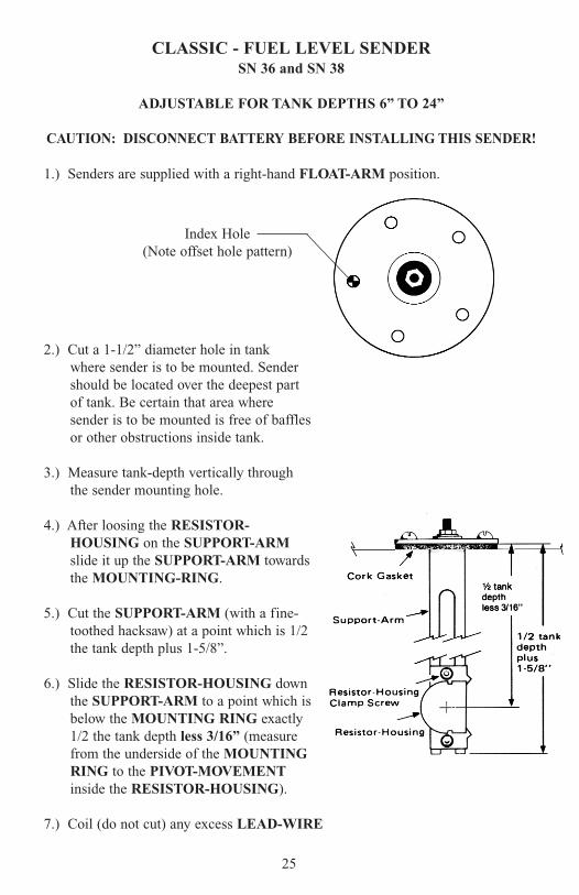
1.) Senders are supplied with a right-hand FLOAT-ARM position.
2.) Cut a 1-1/2” diameter hole in tankwhere sender is to be mounted. Sendershould be located over the deepest partof tank. Be certain that area wheresender is to be mounted is free of bafflesor other obstructions inside tank.
3.) Measure tank-depth vertically throughthe sender mounting hole.
4.) After loosing the RESISTOR-HOUSING on the SUPPORT-ARMslide it up the SUPPORT-ARM towardsthe MOUNTING-RING.
5.) Cut the SUPPORT-ARM (with a fine-toothed hacksaw) at a point which is 1/2the tank depth plus 1-5/8”.
6.) Slide the RESISTOR-HOUSING downthe SUPPORT-ARM to a point which isbelow the MOUNTING RING exactly 1/2 the tank depth less 3/16” (measurefrom the underside of the MOUNTINGRING to the PIVOT-MOVEMENTinside the RESISTOR-HOUSING).
7.) Coil (do not cut) any excess LEAD-WIRE
25
Index Hole(Note offset hole pattern)
so it will not interfere with FLOAT movement.
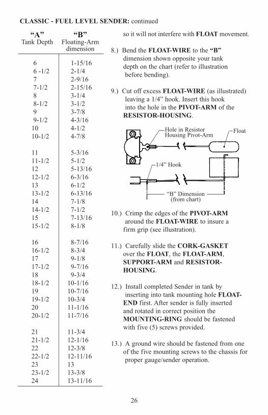
8.) Bend the FLOAT-WIRE to the “B”dimension shown opposite your tankdepth on the chart (refer to illustrationbefore bending).
9.) Cut off excess FLOAT-WIRE (as illustrated)leaving a 1/4” hook. Insert this hookinto the hole in the PIVOT-ARM of the
RESISTOR-HOUSING.
10.) Crimp the edges of the PIVOT-ARMaround the FLOAT-WIRE to insure a
firm grip (see illustration).
11.) Carefully slide the CORK-GASKETover the FLOAT, the FLOAT-ARM,SUPPORT-ARM and RESISTOR-HOUSING.
12.) Install completed Sender in tank by inserting into tank mounting hole FLOAT-
END first. After sender is fully insertedand rotated in correct position the MOUNTING-RING should be fastened with five (5) screws provided.
13.) A ground wire should be fastened from oneof the five mounting screws to the chassis forproper gauge/sender operation.
26
“A” “B”Tank Depth Floating-Arm
dimension
6 1-15/166 -1/2 2-1/47 2-9/167-1/2 2-15/168 3-1/48-1/2 3-1/29 3-7/89-1/2 4-3/16
10 4-1/210-1/2 4-7/8
11 5-3/1611-1/2 5-1/212 5-13/1612-1/2 6-3/1613 6-1/213-1/2 6-13/1614 7-1/814-1/2 7-1/215 7-13/1615-1/2 8-1/8
16 8-7/1616-1/2 8-3/417 9-1/817-1/2 9-7/1618 9-3/418-1/2 10-1/1619 10-7/1619-1/2 10-3/420 11-1/1620-1/2 11-7/16
21 11-3/421-1/2 12-1/1622 12-3/822-1/2 12-11/1623 1323-1/2 13-3/824 13-11/16
CLASSIC - FUEL LEVEL SENDER: continued
Hole in ResistorHousing Pivot-Arm
1/4” Hook
Float
“B” Dimension(from chart)
27
INSTRUMENT SYMPTOMS
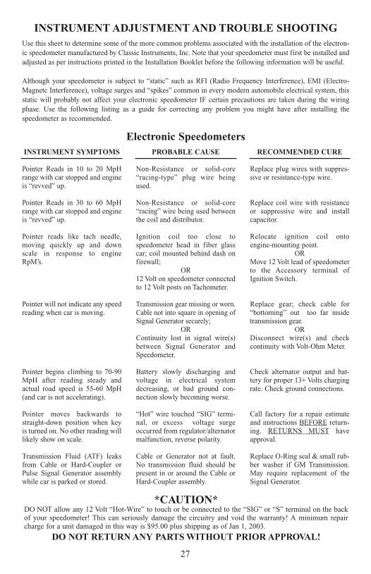
Pointer Reads in 10 to 20 MpHrange with car stopped and engineis “revved” up.
Pointer Reads in 30 to 60 MpHrange with car stopped and engineis “revved” up.
Pointer reads like tach needle,moving quickly up and downscale in response to engineRpM’s.
Pointer will not indicate any speedreading when car is moving.
Pointer begins climbing to 70-90MpH after reading steady andactual road speed is 55-60 MpH(and car is not accelerating).
Pointer moves backwards tostraight-down position when keyis turned on. No other reading willlikely show on scale.
Transmission Fluid (ATF) leaksfrom Cable or Hard-Coupler orPulse Signal Generator assemblywhile car is parked or stored.
PROBABLE CAUSE
Non-Resistance or solid-core“racing-type” plug wire beingused.
Non-Resistance or solid-core“racing” wire being used betweenthe coil and distributor.
Ignition coil too close tospeedometer head in fiber glasscar; coil mounted behind dash onfirewall;
OR12 Volt on speedometer connectedto 12 Volt posts on Tachometer.
Transmission gear missing or worn.Cable not into square in opening ofSignal Generator securely;
ORContinuity lost in signal wire(s)between Signal Generator andSpeedometer.
Battery slowly discharging andvoltage in electrical systemdecreasing, or bad ground con-nection slowly becoming worse.
“Hot” wire touched “SIG” termi-nal, or excess voltage surgeoccurred from regulator/alternatormalfunction, reverse polarity.
Cable or Generator not at fault.No transmission fluid should bepresent in or around the Cable orHard-Coupler assembly.
RECOMMENDED CURE
Replace plug wires with suppres-sive or resistance-type wire.
Replace coil wire with resistanceor suppressive wire and installcapacitor.
Relocate ignition coil ontoengine-mounting point.
ORMove 12 Volt lead of speedometerto the Accessory terminal ofIgnition Switch.
Replace gear; check cable for“bottoming” out too far insidetransmission gear.
ORDisconnect wire(s) and checkcontinuity with Volt-Ohm Meter.
Check alternator output and bat-tery for proper 13+ Volts chargingrate. Check ground connections.
Call factory for a repair estimateand instructions BEFORE return-ing. RETURNS MUST haveapproval.
Replace O-Ring seal & small rub-ber washer if GM Transmission.May require replacement of theSignal Generator.
Electronic Speedometers
*CAUTION*DO NOT allow any 12 Volt “Hot-Wire” to touch or be connected to the “SIG” or “S” terminal on the backof your speedometer! This can seriously damage the circuitry and void the warranty! A minimum repaircharge for a unit damaged in this way is $95.00 plus shipping as of Jan 1, 2003.
DO NOT RETURN ANY PARTS WITHOUT PRIOR APPROVAL!
INSTRUMENT ADJUSTMENT AND TROUBLE SHOOTINGUse this sheet to determine some of the more common problems associated with the installation of the electron-ic speedometer manufactured by Classic Instruments, Inc. Note that your speedometer must first be installed andadjusted as per instructions printed in the Installation Booklet before the following information will be useful.
Although your speedometer is subject to “static” such as RFI (Radio Frequency Interference), EMI (Electro-Magnetc Interference), voltage surges and “spikes” common in every modern automobile electrical system, thisstatic will probably not affect your electronic speedometer IF certain precautions are taken during the wiringphase. Use the following listing as a guide for correcting any problem you might have after installing thespeedometer as recommended.
28
INSTRUMENT SYMPTOMS
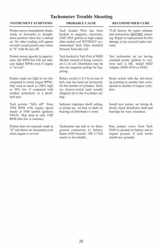
Pointer moves immediately (back-wards or forwards) to straight-down position when key is turnedon. No other reading will appearon scale except pointer may returnto “0” with the key off.
Pointer moves upscale to approxi-mate idle RPM but will not indi-cate higher RPMs even if engineis “revved”.
Pointer reads too high or too lowcompared to actual engine RPMs.May read as much as 200% highor 50% low if compared withanother tachometer or a dwell-tach unit.
Tach pointer “falls off ” from3500 RPM with engine speedsteady at 3500 (points ignitionsONLY). May drop to only 1500RPM (this low is extreme).
Pointer does not respond; reads at“0” and shows no movement evenwhen engine is revved.
PROBABLE CAUSE
Tach Sender Wire has beenhooked to magneto, electronic,GMC-HEI ignition or high-outputafter market coil WITHOUT rec-ommended Tach Filter installedbetween Tach and coil.
Tach hooked to Tach Post of MSDModule instead of being connect-ed (-) of coil. Distributor may bealso use magnetic pickup for trig-gering.
Rotary switch (1-2-3-4) on rear oftach case has been set incorrectlyfor the number of cylinders. Tachsare factory-tested (and usuallyshipped) set to the 4-cylinder set-ting.
Indicates improper dwell setting,or points are set bad, or shaft (orbearing) of distributor is worn.
Tachometer has bad or no directground connection to battery,frame AND firewall - OR 12 Voltsource is not reliable.
RECOMMENDED CURE
*Call factory for repair estimateand instructions BEFORE return-ing. Repair or replacement for thisdamage is not covered under war-ranty.
Test tachometer on car havingstandard points ignition to con-firm tach is OK. Install MSDAdapter (MSD 8910 or 8920).
Reset switch with the slot-arrowtip pointing to number that corre-sponds to number of engine cylin-ders.
Install new points; set timing &dwell; check distributor shaft andbearings for wear, looseness.
Run jumper wires from TachGND to ground on battery and toengine ground. If tach worksinstall new grounds.
Tachometer Trouble Shooting
29
INSTRUMENT SYMPTOMS
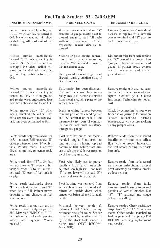
Pointer moves quickly to beyondFULL whenever key is turned toON. No other reading will showon dial irregardless of level of fuelin tank.
Pointer moves immediatelybeyond FULL whenever key isturned ON - EVEN if the fuel tankis empty. No other reading willshow on the dial whenever theignition key switch is turned toON.
Pointer moves immediatelybeyond FULL whenever key isturned ON - EVEN if the groundand sender wires and connectionshave been checked and found OK.
Pointer moves below “E” whenkey is switched ON and will notmove upscale even if the fuel leveltank has been confirmed as full.
Pointer reads only from about 1/4to 3/4 on scale. Will not show “E”on empty tank or show “F” on fulltank. Pointer reads in correctdirection but only on center scalearea.
Pointer reads from “E” to 3/4 butwill not move to “F” even will fulltank; or reads 1/4 to “F” but willnot read “E” even if fuel tank isempty.
Pointer reads backwards; shows“F” when tank is empty and “E”when tank if full. Pointer movesopposite to any changes in fuellevel in tank.
Pointer reads in error; may read inreverse or reads only on part ofdial. May read EMPTY or FULLbut only on part of scale (pointersweep area appears “com-pressed”).
PROBABLE CAUSE
Wire between sender unit and “S”terminal of gauge shorting out toground; gauge to read full scalewithout resistance. Circuitbypassing sender directly toground.
Missing or poor ground connec-tion between sender mountingplate and “G” terminal on rear ofthe instrument case;
ORPoor ground between engine andfirewall (dash grounding strap iffiberglass car).
Tank sender has been disassem-bled and the reassembled incor-rectly. Result is incomplete circuitfrom metal mounting plate to thevertical bracket.
Break in wiring harness betweenterminal post of tank sending unitand “S” terminal on back of theinstrument case. Loss of continu-ity causes maximum resistancethrough the gauge.
Float wire not cut to the recom-mended length. Float arm toolong and float is hitting top andbottom of tank before float armcan touch upper & lower stops onpivot housing assembly.
Float wire likely cut to properlength - BUT pivot assemblyadjusted too high (will not read“F”) or too low (will not read “E”)on vertical mounting bracket.
Pivot housing was removed fromvertical bracket on tank sender &reinstalled upside down whensender was being adjusted for tankdepth.
Mismatch between sender &instrument. Tank Sender is wrongresistance range for gauge. Sendermanufactured by another compa-ny, or the stock tank sender isbeing used (NOT RECOM-MENDED).
RECOMMENDED CURE
Use new “jumper wire” outside ofharness to replace wire betweensender terminal and “S” post onback of instrument case.
Disconnect wire from sender plateand “G” post of instrument. Run“jumper” between sender andgauge. If pointer reads correctrewire instrument and senderground wires.
Remove sender unit and reassem-ble correctly; or return sender forrepair. Contact your ClassicInstrument Technician for repaircost.
Check by connecting jumper wirefrom “S” on gauge to terminal onsender (disconnect harnesssender-gauge wire before hookingup any jumper wires.)
Remove sender from tank: rereadinstallation instructions: adjustfloat wire to proper dimensionsand test before putting unit backinto tank.
Remove sender from tank: rereadinstallation instructions: readjustpivot assembly on vertical brack-et. Test, reinstall.
Remove sender from tank:remount pivot housing in correctposition on vertical bracket. Test“E” - “F” readings into gaugebefore reinstalling.
Remove sender. Check resistancerange from “E” TO “F” on ohm-meter. Order sender matched tofuel gauge (check fuel gauge P/NBEFORE ordering replacementtank sender).
Fuel Tank Sender: 33 - 240 OHM
INSTRUMENT SYMPTOMS
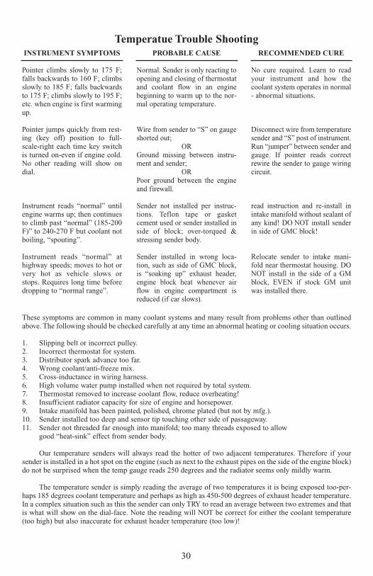
Pointer climbs slowly to 175 F;falls backwards to 160 F; climbsslowly to 185 F; falls backwardsto 175 F; climbs slowly to 195 F;etc. when engine is first warmingup.
Pointer jumps quickly from rest-ing (key off) position to full-scale-right each time key switchis turned on-even if engine cold.No other reading will show ondial.
Instrument reads “normal” untilengine warms up; then continuesto climb past “normal” (185-200F)” to 240-270 F but coolant notboiling, “spouting”.
Instrument reads “normal” athighway speeds; moves to hot orvery hot as vehicle slows orstops. Requires long time beforedropping to “normal range”.
PROBABLE CAUSE
Normal. Sender is only reacting toopening and closing of thermostatand coolant flow in an enginebeginning to warm up to the nor-mal operating temperature.
Wire from sender to “S” on gaugeshorted out;
ORGround missing between instru-ment and sender;
ORPoor ground between the engineand firewall.
Sender not installed per instruc-tions. Teflon tape or gasketcement used or sender installed inside of block; over-torqued &stressing sender body.
Sender installed in wrong loca-tion, such as side of GMC block,is “soaking up” exhaust header,engine block heat whenever airflow in engine compartment isreduced (if car slows).
RECOMMENDED CURE
No cure required. Learn to readyour instrument and how thecoolant system operates in normal- abnormal situations.
Disconnect wire from temperaturesender and “S” post of instrument.Run “jumper” between sender andgauge. If pointer reads correctrewire the sender to gauge wiringcircuit.
read instruction and re-install inintake manifold without sealant ofany kind! DO NOT install senderin side of GMC block!
Relocate sender to intake mani-fold near thermostat housing. DONOT install in the side of a GMblock, EVEN if stock GM unitwas installed there.
Temperatue Trouble Shooting
These symptoms are common in many coolant systems and many result from problems other than outlinedabove. The following should be checked carefully at any time an abnormal heating or cooling situation occurs.
1. Slipping belt or incorrect pulley.2. Incorrect thermostat for system.3. Distributor spark advance too far.4. Wrong coolant/anti-freeze mix.5. Cross-inductance in wiring harness.6. High volume water pump installed when not required by total system.7. Thermostat removed to increase coolant flow, reduce overheating!8. Insufficient radiator capacity for size of engine and horsepower.9. Intake manifold has been painted, polished, chrome plated (but not by mfg.).10. Sender installed too deep and sensor tip touching other side of passageway.11. Sender not threaded far enough into manifold; too many threads exposed to allow
good “heat-sink” effect from sender body.
Our temperature senders will always read the hotter of two adjacent temperatures. Therefore if yoursender is installed in a hot spot on the engine (such as next to the exhaust pipes on the side of the engine block)do not be surprised when the temp gauge reads 250 degrees and the radiator seems only mildly warm.
The temperature sender is simply reading the average of two temperatures it is being exposed too-per-haps 185 degrees coolant temperature and perhaps as high as 450-500 degrees of exhaust header temperature.In a complex situation such as this the sender can only TRY to read an average between two extremes and thatis what will show on the dial-face. Note the reading will NOT be correct for either the coolant temperature(too high) but also inaccurate for exhaust header temperature (too low)!
30
31
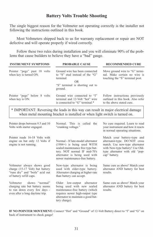
INSTRUMENT SYMPTOMS
Pointer “pegs” past 18 voltswhen key is turned ON.
Pointer “pegs” below 8 voltswhen key is ON.
Pointer drops between 9.5 and 10Volts with starter engaged.
Pointer reads 16-18 Volts withengine on but only 12 Volts ifengine is not running.
Voltmeter always shows goodcharge (15-17 Volt) but battery“runs dry” and “boils” acid outof battery refill caps.
Voltmeter shows “normal”charging rate but battery seemsto run down every few days -even after a long daytime trip.
PROBABLE CAUSE
Ground wire has been connectedto “S” stud instead of the “G”terminal.
OR“S” terminal is shorting out toground.
Ground wire connected to “I”terminal and 12-Volt “hot” wireis connected to “G” terminal.*
Normal. This is called the“cranking voltage.”
Normal - If late-model alternator(1984+) is being used WITHsealed maintenance free type bat-tery. NOT normal IF mid-70’salternator is being used withnewer maintenance-free battery.
New-type alternator is beingused with older-type battery.Alternator charging at higher ratethan battery can accept.
Older low-output alternatorbeing used with new sealedmaintenance-free battery (whichrequires newer high-output typealternator to maintain a good bat-tery charge).
RECOMMENDED CURE
Move ground wire to “G” termi-nal. Make certain no wire istouching the “S” terminal post.
Follow instructions previouslyoutlined in this book. Also referto the above stated cure.
No cure required. Learn to readyour instrument and how it reactsin normal operating situations.
Match your battery-type andalternator-type. DO NOT crossmatch. Use new-type alternatorwith New-type battery! Use Old-type alternator with old “pop-cap” battery.
Same cure as above! Match youralternator AND battery for bestresults.
Same cure as above! Match youralternator AND battery for bestresults.
Battery Volts Trouble Shooting
* IMPORTANT: Reversing the leads in this way can result in major electrical damagewhen metal mounting bracket is installed or when light switch is turned on.
IF NO POINTER MOVEMENT: Connect “Hot” and “Ground” of 12-Volt Battery direct to “I” and “G” onback of instrument to check gauge!
The single biggest reason for the Voltmeter not operating correctly is the installer notfollowing the instructions outlined in this book.
Most Voltmeters shipped back to us for warranty replacement or repair are NOTdefective and will operate properly if wired correctly.
Follow these two rules during installation and you will eliminate 90% of the prob-lems that cause builders to believe they have a “bad” gauge.

32
Notes

33
Notes
Classic Instruments, Inc.P.O. Box 411 or 1299 M-75 SouthBoyne City, Michigan 49712 USA
Technical Assistance231-582-0461 or 800-575-0461
U.S.A. $3.00