Embed Size (px)
Citation preview

SOFTWARE – PRACTICE AND EXPERIENCESoftw. Pract. Exper. 2011; 41:23–50Published online 24 August 2010 in Wiley Online Library (wileyonlinelibrary.com). DOI: 10.1002/spe.995
CloudSim: a toolkit for modeling and simulation of cloudcomputing environments and evaluation of resource
provisioning algorithms
Rodrigo N. Calheiros1, Rajiv Ranjan2, Anton Beloglazov1, Cesar A. F. De Rose3
and Rajkumar Buyya1,∗,†
1Cloud Computing and Distributed Systems (CLOUDS) Laboratory, Department of Computer Science and SoftwareEngineering, The University of Melbourne, Australia
2School of Computer Science and Engineering, The University of New South Wales, Sydney, Australia3Department of Computer Science, Pontifical Catholic University of Rio Grande do Sul, Porto Alegre, Brazil
SUMMARY
Cloud computing is a recent advancement wherein IT infrastructure and applications are provided as‘services’ to end-users under a usage-based payment model. It can leverage virtualized services even on thefly based on requirements (workload patterns and QoS) varying with time. The application services hostedunder Cloud computing model have complex provisioning, composition, configuration, and deploymentrequirements. Evaluating the performance of Cloud provisioning policies, application workload models,and resources performance models in a repeatable manner under varying system and user configurationsand requirements is difficult to achieve. To overcome this challenge, we propose CloudSim: an extensiblesimulation toolkit that enables modeling and simulation of Cloud computing systems and applicationprovisioning environments. The CloudSim toolkit supports both system and behavior modeling of Cloudsystem components such as data centers, virtual machines (VMs) and resource provisioning policies.It implements generic application provisioning techniques that can be extended with ease and limitedeffort. Currently, it supports modeling and simulation of Cloud computing environments consisting ofboth single and inter-networked clouds (federation of clouds). Moreover, it exposes custom interfaces forimplementing policies and provisioning techniques for allocation of VMs under inter-networked Cloudcomputing scenarios. Several researchers from organizations, such as HP Labs in U.S.A., are usingCloudSim in their investigation on Cloud resource provisioning and energy-efficient management ofdata center resources. The usefulness of CloudSim is demonstrated by a case study involving dynamicprovisioning of application services in the hybrid federated clouds environment. The result of this case studyproves that the federated Cloud computing model significantly improves the application QoS requirementsunder fluctuating resource and service demand patterns. Copyright q 2010 John Wiley & Sons, Ltd.
Received 3 November 2009; Revised 4 June 2010; Accepted 14 June 2010
KEY WORDS: Cloud computing; modelling and simulation; performance evaluation; resource manage-ment; application scheduling
1. INTRODUCTION
Cloud computing delivers infrastructure, platform, and software that are made available assubscription-based services in a pay-as-you-go model to consumers. These services are referredto as Infrastructure as a Service (IaaS), Platform as a Service (PaaS), and Software as a Service(SaaS) in industries. The importance of these services was highlighted in a recent report from theUniversity of Berkeley as: ‘Cloud computing, the long-held dream of computing as a utility has
∗Correspondence to: Rajkumar Buyya, Cloud Computing and Distributed Systems (CLOUDS) Laboratory, Departmentof Computer Science and Software Engineering, The University of Melbourne, Australia.
†E-mail: [email protected]
Copyright q 2010 John Wiley & Sons, Ltd.

24 R. N. CALHEIROS ET AL.
the potential to transform a large part of the IT industry, making software even more attractive asa service’ [1].
Clouds [2] aim to power the next-generation data centers as the enabling platform for dynamicand flexible application provisioning. This is facilitated by exposing data center’s capabilities as anetwork of virtual services (e.g. hardware, database, user-interface, and application logic) so thatusers are able to access and deploy applications from anywhere in the Internet driven by the demandand Quality of Service (QoS) requirements [3]. Similarly, IT companies with innovative ideas fornew application services are no longer required to make large capital outlays in the hardware andsoftware infrastructures. By using clouds as the application hosting platform, IT companies arefreed from the trivial task of setting up basic hardware and software infrastructures. Thus, theycan focus more on innovation and creation of business values for their application services [1].
Some of the traditional and emerging Cloud-based application services include social networking,web hosting, content delivery, and real-time instrumented data processing. Each of these appli-cation types has different composition, configuration, and deployment requirements. Quantifyingthe performance of provisioning (scheduling and allocation) policies in a real Cloud computingenvironment (Amazon EC2 [4], Microsoft Azure [5], Google App Engine [6]) for different appli-cation models under transient conditions is extremely challenging because: (i) Clouds exhibitvarying demands, supply patterns, system sizes, and resources (hardware, software, network);(ii) users have heterogeneous, dynamic, and competing QoS requirements; and (iii) applicationshave varying performance, workload, and dynamic application scaling requirements. The use ofreal infrastructures, such as Amazon EC2 and Microsoft Azure, for benchmarking the applicationperformance (throughput, cost benefits) under variable conditions (availability, workload patterns)is often constrained by the rigidity of the infrastructure. Hence, this makes the reproduction ofresults that can be relied upon, an extremely difficult undertaking. Further, it is tedious and time-consuming to re-configure benchmarking parameters across a massive-scale Cloud computinginfrastructure over multiple test runs. Such limitations are caused by the conditions prevailing in theCloud-based environments that are not in the control of developers of application services. Thus,it is not possible to perform benchmarking experiments in repeatable, dependable, and scalableenvironments using real-world Cloud environments.
A more viable alternative is the use of simulation tools. These tools open up the possibilityof evaluating the hypothesis (application benchmarking study) in a controlled environment whereone can easily reproduce results. Simulation-based approaches offer significant benefits to ITcompanies (or anyone who wants to offer his application services through clouds) by allowingthem to: (i) test their services in repeatable and controllable environment; (ii) tune the systembottlenecks before deploying on real clouds; and (iii) experiment with different workload mix andresource performance scenarios on simulated infrastructures for developing and testing adaptiveapplication provisioning techniques [7].
Considering that none of the current distributed (including Grid and Network) system simulators[8–10] offer the environment that can be directly used for modeling Cloud computing environ-ments, we present CloudSim: a new, generalized, and extensible simulation framework that allowsseamless modeling, simulation, and experimentation of emerging Cloud computing infrastructuresand application services. By using CloudSim, researchers and industry-based developers can testthe performance of a newly developed application service in a controlled and easy to set-up environ-ment. Based on the evaluation results reported by CloudSim, they can further finetune the serviceperformance. The main advantages of using CloudSim for initial performance testing include:(i) time effectiveness: it requires very less effort and time to implement Cloud-based applicationprovisioning test environment and (ii) flexibility and applicability: developers can model and testthe performance of their application services in heterogeneous Cloud environments (Amazon EC2,Microsoft Azure) with little programming and deployment effort.
CloudSim offers the following novel features: (i) support for modeling and simulation of large-scale Cloud computing environments, including data centers, on a single physical computingnode; (ii) a self-contained platform for modeling Clouds, service brokers, provisioning, and allo-cation policies; (iii) support for simulation of network connections among the simulated system
Copyright q 2010 John Wiley & Sons, Ltd. Softw. Pract. Exper. 2011; 41:23–50DOI: 10.1002/spe
CLOUDSIM: A TOOLKIT 25
elements; and (iv) facility for simulation of federated Cloud environment that inter-networksresources from both private and public domains, a feature critical for research studies related toCloud-Bursts and automatic application scaling. Some of the unique features of CloudSim are:(i) availability of a virtualization engine that aids in the creation and management of multiple,independent, and co-hosted virtualized services on a data center node and (ii) flexibility to switchbetween space-shared and time-shared allocation of processing cores to virtualized services. Thesecompelling features of CloudSim would speed up the development of new application provisioningalgorithms for Cloud computing.
The main contributions of this paper are: (i) a holistic software framework for modeling Cloudcomputing environments and performance testing application services and (ii) an end-to-end Cloudnetwork architecture that utilizes BRITE topology for modeling link bandwidth and associatedlatencies. Some of our findings related to the CloudSim framework are: (i) it is capable of supportinga large-scale simulation environment with little or no overhead with respect to initialization over-head and memory consumption; (ii) it exposes powerful features that could easily be extendedfor modeling custom Cloud computing environments (federated/non-federated) and applicationprovisioning techniques (Cloud-Bursts, energy conscious/non-energy conscious).
The remainder of this paper is organized as follows: first, a general description about Cloudcomputing, existing models, and their layered design is presented. This section ends with a briefoverview of existing state-of-the-art in distributed (grids, clouds) system simulation and modeling.Following that, comprehensive details related to the architecture of the CloudSim framework arepresented. Section 4 presents the overall design of the CloudSim components. Section 5 presents aset of experiments that were conducted for quantifying the performance of CloudSim in successfullysimulating Cloud computing environments. Section 6 gives a brief overview of the projects thatare using or have used CloudSim for research and development. Finally, the paper ends with briefconclusive remarks and a discussion on future research directions.
2. BACKGROUND
This section presents the background information on various elements that form the basis forarchitecting Cloud computing systems. It also presents the requirements of elastic or malleableapplications that need to scale across multiple, geographically distributed data centers that areowned by one or more Cloud service providers. The CloudSim framework aims to ease-up andspeed the process of conducting experimental studies that use Cloud computing as the applicationprovisioning environments. Note that, conducting such experimental studies using real Cloudinfrastructures can be extremely time-consuming due to their sheer scale and complexity.
2.1. Cloud computing
Cloud computing can be defined as ‘a type of parallel and distributed system consisting of acollection of inter-connected and virtualized computers that are dynamically provisioned, andpresented as one or more unified computing resources based on service-level agreements establishedthrough negotiation between the service provider and consumers’ [3]. Some of the examplesfor emerging Cloud computing infrastructures/platforms are Microsoft Azure [5], Amazon EC2,Google App Engine, and Aneka [11].
One implication of Cloud platforms is the ability to dynamically adapt (scale-up or scale-down)the amount of resources provisioned to an application in order to attend the variations in demand thatare either predictable, and occur due to access patterns observed during the day and during the night;or unexpected, and occurring due to a subtle increase in the popularity of the application service.This capability of clouds is especially useful for elastic (automatically scaling of) applications,such as web hosting, content delivery, and social networks that are susceptible to such behavior.
These applications often exhibit transient behavior (usage pattern) and have different QoSrequirements depending on time criticality and users’ interaction patterns (online/offline). Hence,
Copyright q 2010 John Wiley & Sons, Ltd. Softw. Pract. Exper. 2011; 41:23–50DOI: 10.1002/spe
26 R. N. CALHEIROS ET AL.
the development of dynamic provisioning techniques to ensure that these applications achieve QoSunder transient conditions is required.
Although Cloud has been increasingly seen as the platform that can support elastic applications,it faces certain limitations pertaining to core issues such as ownership, scale, and locality. Forinstance, a cloud can only offer a limited number of hosting capability (virtual machines (VMs)and computing servers) to application services at a given instance of time; hence, scaling the appli-cation’s capacity beyond a certain extent becomes complicated. Therefore, in those cases where thenumber of requests overshoots the cloud’s capacity, application hosted in a cloud can compromiseon the overall QoS delivered to its users. One solution to this problem is to inter-network multipleclouds as part of a federation and develop next-generation dynamic provisioning techniques thatcan derive benefits from the architecture. Such federation of geographically distributed cloudscan be formed based on previous agreements among them, to efficiently cope with variations inservice demands. This approach allows provisioning of applications across multiple clouds thatare members of a/the federation. This further aids in efficiently fulfilling user SLAs through trans-parent migration of application service instance to the cloud in the federation, which is closer tothe origins of requests.
A hybrid cloud model is a combination of private clouds with public clouds. Private and publicclouds mainly differ on the type of ownership and access rights that they support. Access toprivate cloud resources is restricted to the users belonging to the organization that owns thecloud. On the other hand, public cloud resources are available on the Internet to any interesteduser under pay-as-you-go model. Hence, small and medium enterprises (SMEs) and governmentshave started exploring demand-driven provisioning of public clouds along with their existingcomputing infrastructures (private clouds) for handling the temporal variation in their servicedemands. This model is particularly beneficial for SMEs and banks that need massive computingpower only at a particular time of the day (such as back-office processing, transaction analysis).However, writing the software and developing application provisioning techniques for any ofthe Cloud models—public, private, hybrid, or federated—is a complex undertaking. There areseveral key challenges associated with provisioning of applications on clouds: service discovery,monitoring, deployment of VMs and applications, and load-balancing among others. The effectof each element in the overall Cloud operation may not be trivial enough to allow isolation,evaluation, and reproduction. CloudSim eases these challenges by supplying a platform in whichstrategies for each element can be tested in a controlled and reproducible manner. Therefore,simulation frameworks such as CloudSim are important, as they allow the evaluation of theperformance of resource provisioning and application scheduling techniques under different usageand infrastructure availability scenarios.
2.2. Layered design
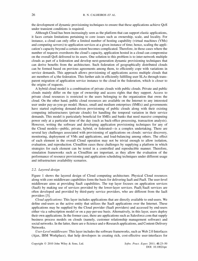
Figure 1 shows the layered design of Cloud computing architecture. Physical Cloud resourcesalong with core middleware capabilities form the basis for delivering IaaS and PaaS. The user-levelmiddleware aims at providing SaaS capabilities. The top layer focuses on application services(SaaS) by making use of services provided by the lower-layer services. PaaS/SaaS services areoften developed and provided by third-party service providers, who are different from the IaaSproviders [3].
Cloud applications: This layer includes applications that are directly available to end-users. Wedefine end-users as the active entity that utilizes the SaaS applications over the Internet. Theseapplications may be supplied by the Cloud provider (SaaS providers) and accessed by end-userseither via a subscription model or on a pay-per-use basis. Alternatively, in this layer, users deploytheir own applications. In the former case, there are applications such as Salesforce.com that supplybusiness process models on clouds (namely, customer relationship management software) andsocial networks. In the latter, there are e-Science and e-Research applications, and Content-DeliveryNetworks.
User-Level middleware: This layer includes the software frameworks, such as Web 2.0 Interfaces(Ajax, IBM Workplace), that help developers in creating rich, cost-effective user-interfaces for
Copyright q 2010 John Wiley & Sons, Ltd. Softw. Pract. Exper. 2011; 41:23–50DOI: 10.1002/spe
CLOUDSIM: A TOOLKIT 27
Cloud resources
Virtual Machine (VM), VM Management and Deployment
QoS Negotiation, Admission Control, Pricing, SLA Management, Monitoring, Execution Management, Metering, Accounting, Billing
Cloud programming: environments and toolsWeb 2.0 Interfaces, Mashups, Concurrent and Distributed
Programming, Workflows, Libraries, Scripting
Cloud applicationsSocial computing, Enterprise, ISV, Scientific, CDNs, ...
Adaptive M
anagement
CoreMiddleware
( PaaS)
User-LevelMiddleware
( SaaS)
System level(IaaS)
User level
Autonom
ic / Cloud E
conomy
Apps Hosting Platforms
Figure 1. Layered cloud computing architecture.
browser-based applications. The layer also provides those programming environments and compo-sition tools that ease the creation, deployment, and execution of applications in clouds. Finally, inthis layer several frameworks that support multi-layer applications development, such as Springand Hibernate, can be deployed to support applications running in the upper level.
Core middleware: This layer implements the platform-level services that provide run-time envi-ronment for hosting and managing User-Level application services. The core services at this layerinclude Dynamic SLA Management, Accounting, Billing, Execution monitoring and management,and Pricing (are all the services to be capitalized?). The well-known examples of services operatingat this layer are Amazon EC2, Google App Engine, and Aneka. The functionalities exposed by thislayer are accessed by both SaaS (the services represented at the top-most layer in Figure 1) andIaaS (services shown at the bottom-most layer in Figure 1) services. Critical functionalities thatneed to be realized at this layer include messaging, service discovery, and load-balancing. Thesefunctionalities are usually implemented by Cloud providers and offered to application developersat an additional premium. For instance, Amazon offers a load-balancer and a monitoring service(Cloudwatch) for the Amazon EC2 developers/consumers. Similarly, developers building applica-tions on Microsoft Azure clouds can use the .NET Service Bus for implementing message passingmechanism.
System Level: The computing power in Cloud environments is supplied by a collection of datacenters that are typically installed with hundreds to thousands of hosts [2]. At the System-Levellayer, there exist massive physical resources (storage servers and application servers) that powerthe data centers. These servers are transparently managed by the higher-level virtualization [12]services and toolkits that allow sharing of their capacity among virtual instances of servers. TheseVMs are isolated from each other, thereby making fault tolerant behavior and isolated securitycontext possible.
2.3. Federation (inter-networking) of clouds
Current Cloud computing providers have several data centers at different geographical locationsover the Internet in order to optimally serve customer needs around the world. However, theexisting systems do not support mechanisms and policies for dynamically coordinating load-shredding among different data centers in order to determine the optimal location for hostingapplication services to achieve reasonable QoS levels. Further, the Cloud service providers are
Copyright q 2010 John Wiley & Sons, Ltd. Softw. Pract. Exper. 2011; 41:23–50DOI: 10.1002/spe
28 R. N. CALHEIROS ET AL.
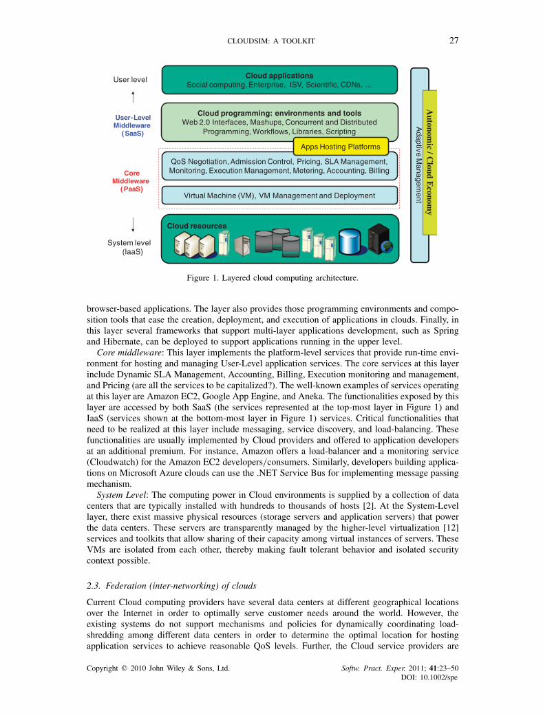
Figure 2. Clouds and their federated network.
unable to predict the geographic distribution of end-users consuming their services; hence, the loadcoordination must happen automatically, and distribution of services must change in response tochanges in the load behavior. Figure 2 depicts such a Cloud computing architecture that consistsof service consumers’ (SaaS providers’) brokering and providers’ coordinator services that supportutility-driven internetworking of clouds [13]: application provisioning and workload migration.
Federated inter-networking of administratively distributed clouds offers significant performanceand financial benefits such as: (i) improving the ability of SaaS providers in meeting QoS levels forclients and offer improved service by optimizing the service placement and scale; (ii) enhancing thepeak-load handling and dynamic system expansion capacity of every member cloud by allowingthem to dynamically acquire additional resources from federation. This frees the Cloud providersfrom the need of setting up a new data center in every location; and (iii) adapting to failures, suchas natural disasters and regular system maintenance, is more graceful as providers can transparentlymigrate their services to other domains in the federation, thus avoiding SLA violations and theresulting penalties. Hence, federation of clouds not only ensures business continuity but alsoaugments the reliability of the participating Cloud providers.
One of the key components of the architecture presented in Figure 2 is the Cloud Coordinator.This component is instantiated by each cloud in the system whose responsibility is to undertake thefollowing important activities: (i) exporting Cloud services, both infrastructure and platform-level,to the federation; (ii) keeping track of load on the Cloud resources (VMs, computing services)and undertaking negotiation with other Cloud providers in the federation for handling the suddenpeak in resource demand at local cloud; and (iii) monitoring the application execution over itslife cycle and overseeing that the agreed SLAs are delivered. The Cloud brokers acting on behalfof SaaS providers identify suitable Cloud service providers through the Cloud Exchange (CEx).Further, Cloud brokers can also negotiate with the respective Cloud Coordinators for allocationof resources that meets the QoS needs of hosted or to be hosted SaaS applications. The CEx actsas a market maker by bringing together Cloud service (IaaS) and SaaS providers. CEx aggregatesthe infrastructure demands from the Cloud brokers and evaluates them against the available supplycurrently published by the Cloud Coordinators.
The applications that may benefit from the aforementioned federated Cloud computing infras-tructure include social networks such as Facebook and MySpace, and Content-Delivery Networks
Copyright q 2010 John Wiley & Sons, Ltd. Softw. Pract. Exper. 2011; 41:23–50DOI: 10.1002/spe
CLOUDSIM: A TOOLKIT 29
(CDNs). Social networking sites serve dynamic contents to millions of users, whose access andinteraction patterns are difficult to predict. In general, social networking web sites are built usingmulti-tiered web applications such as WebSphere and persistency layers like the MySQL rela-tional database. Usually, each component will run on a different VM, which can be hosted indata centers owned by different Cloud computing providers. Additionally, each plug-in developerhas the freedom to choose which Cloud computing provider offers the services that are moresuitable to run his/her plug-in. As a consequence, a typical social networking web applicationis formed by hundreds of different services, which may be hosted by dozens of Cloud-orienteddata centers around the world. Whenever there is a variation in the temporal and spatial localityof workload (usage pattern), each application component must dynamically scale to offer goodquality of experience to users.
Domain experts and scientists can also take advantage of such mechanisms by using the cloud toleverage resources for their high-throughput e-Science applications, such as Monte–Carlo simula-tion and Medical Image Registration. In this scenario, the clouds can be augmented to the existingcluster and grid-based resource pool to meet research deadlines and milestones.
2.4. Related work
In the past decade, Grids [14] have evolved as the infrastructure for delivering high-performanceservices for compute- and data-intensive scientific applications. To support research, development,and testing of new Grid components, policies, and middleware, several Grid simulators, such asGridSim [10], SimGrid [9], OptorSim [15], and GangSim [8], have been proposed. SimGrid is ageneric framework for simulation of distributed applications on Grid platforms. Similarly, GangSimis a Grid simulation toolkit that provides support for modeling of Grid-based virtual organizationsand resources. On the other hand, GridSim is an event-driven simulation toolkit for heterogeneousGrid resources. It supports comprehensive modeling of grid entities, users, machines, and network,including network traffic.
Although the aforementioned toolkits are capable of modeling and simulating the Grid applica-tion management behaviors (execution, provisioning, discovery, and monitoring), none of them areable to clearly isolate the multi-layer service abstractions (SaaS, PaaS, and IaaS) differentiationrequired by Cloud computing environments. In particular, there is very little or no support inexisting Grid simulation toolkits for modeling of virtualization-enabled resource and applicationmanagement environment. Clouds promise to deliver services on subscription-basis in a pay-as-you-go model to SaaS providers. Therefore, Cloud environment modeling and simulation toolkitsmust provide support for economic entities, such as Cloud brokers and CEx, for enabling real-timetrading of services between customers and providers. Among the currently available simulatorsdiscussed in this paper, only GridSim offers support for economic-driven resource managementand application provisioning simulation. Moreover, none of the currently available Grid simulatorsoffer support for simulation of virtualized infrastructures, neither have they provided tools formodeling data-center type of environments that can consist of hundred-of-thousands of computingservers.
Recently, Yahoo and HP have led the establishment of a global Cloud computing testbed, calledOpen Cirrus, supporting a federation of data centers located in 10 organizations [16]. Building suchexperimental environments is expensive and hard to conduct repeatable experiments as resourceconditions vary from time to time due to its shared nature. Also, their accessibility is limited tomembers of this collaboration. Hence, simulation environments play an important role.
As Cloud computing R&D is still in the infancy stage [1], a number of important issuesneed detailed investigation along the layered Cloud computing architecture (see Figure 1). Topicsof interest include economic and also energy-efficient strategies for provisioning of virtualizedresources to end-user’s requests, inter-cloud negotiations, and federation of clouds. To supportand accelerate the research related to Cloud computing systems, applications and services, it isimportant that the necessary software tools are designed and developed to aid researchers andindustrial developers.
Copyright q 2010 John Wiley & Sons, Ltd. Softw. Pract. Exper. 2011; 41:23–50DOI: 10.1002/spe
30 R. N. CALHEIROS ET AL.
3. CLOUDSIM ARCHITECTURE
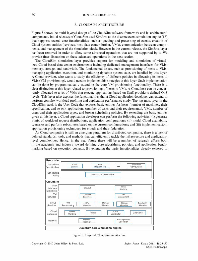
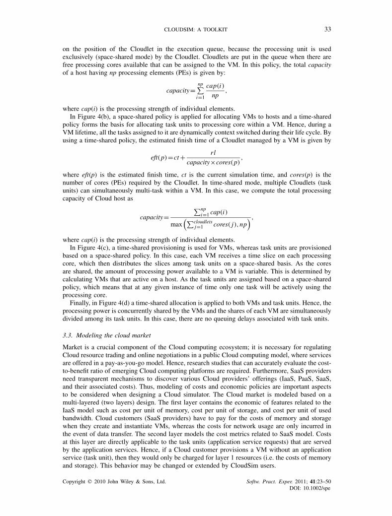
Figure 3 shows the multi-layered design of the CloudSim software framework and its architecturalcomponents. Initial releases of CloudSim used SimJava as the discrete event simulation engine [17]that supports several core functionalities, such as queuing and processing of events, creation ofCloud system entities (services, host, data center, broker, VMs), communication between compo-nents, and management of the simulation clock. However in the current release, the SimJava layerhas been removed in order to allow some advanced operations that are not supported by it. Weprovide finer discussion on these advanced operations in the next section.
The CloudSim simulation layer provides support for modeling and simulation of virtual-ized Cloud-based data center environments including dedicated management interfaces for VMs,memory, storage, and bandwidth. The fundamental issues, such as provisioning of hosts to VMs,managing application execution, and monitoring dynamic system state, are handled by this layer.A Cloud provider, who wants to study the efficiency of different policies in allocating its hosts toVMs (VM provisioning), would need to implement his strategies at this layer. Such implementationcan be done by programmatically extending the core VM provisioning functionality. There is aclear distinction at this layer related to provisioning of hosts to VMs. A Cloud host can be concur-rently allocated to a set of VMs that execute applications based on SaaS provider’s defined QoSlevels. This layer also exposes the functionalities that a Cloud application developer can extend toperform complex workload profiling and application performance study. The top-most layer in theCloudSim stack is the User Code that exposes basic entities for hosts (number of machines, theirspecification, and so on), applications (number of tasks and their requirements), VMs, number ofusers and their application types, and broker scheduling policies. By extending the basic entitiesgiven at this layer, a Cloud application developer can perform the following activities: (i) generatea mix of workload request distributions, application configurations; (ii) model Cloud availabilityscenarios and perform robust tests based on the custom configurations; and (iii) implement customapplication provisioning techniques for clouds and their federation.
As Cloud computing is still an emerging paradigm for distributed computing, there is a lack ofdefined standards, tools, and methods that can efficiently tackle the infrastructure and application-level complexities. Hence, in the near future there will be a number of research efforts bothin the academia and industry toward defining core algorithms, policies, and application bench-marking based on execution contexts. By extending the basic functionalities already exposed to
EventsHandling
CloudSim core simulation engine
Data CenterCloud
Resources
VMProvisioning
CPUAllocation
MemoryAllocation
StorageAllocation
BandwidthAllocation
CloudServices
CloudletExecution
VMServices
UserInterface
Structures
CloudSim
User code
User or Data Center BrokerScheduling
Policy
CloudScenario
ApplicationConfiguration
UserRequirements …Simulation
Specification
VMManagement
NetworkTopology
Message delayCalculationNetwork
CloudCoordinator
Sensor
CloudletVirtual
Machine
Figure 3. Layered CloudSim architecture.
Copyright q 2010 John Wiley & Sons, Ltd. Softw. Pract. Exper. 2011; 41:23–50DOI: 10.1002/spe
CLOUDSIM: A TOOLKIT 31
CloudSim, researchers will be able to perform tests based on specific scenarios and configurations,thereby allowing the development of best practices in all the critical aspects related to CloudComputing.
3.1. Modeling the cloud
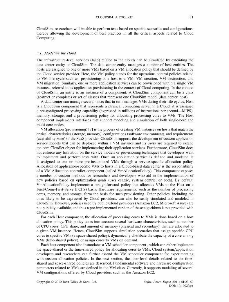
The infrastructure-level services (IaaS) related to the clouds can be simulated by extending thedata center entity of CloudSim. The data center entity manages a number of host entities. Thehosts are assigned to one or more VMs based on a VM allocation policy that should be defined bythe Cloud service provider. Here, the VM policy stands for the operations control policies relatedto VM life cycle such as: provisioning of a host to a VM, VM creation, VM destruction, andVM migration. Similarly, one or more application services can be provisioned within a single VMinstance, referred to as application provisioning in the context of Cloud computing. In the contextof CloudSim, an entity is an instance of a component. A CloudSim component can be a class(abstract or complete) or set of classes that represent one CloudSim model (data center, host).
A data center can manage several hosts that in turn manages VMs during their life cycles. Hostis a CloudSim component that represents a physical computing server in a Cloud: it is assigneda pre-configured processing capability (expressed in millions of instructions per second—MIPS),memory, storage, and a provisioning policy for allocating processing cores to VMs. The Hostcomponent implements interfaces that support modeling and simulation of both single-core andmulti-core nodes.
VM allocation (provisioning) [7] is the process of creating VM instances on hosts that match thecritical characteristics (storage, memory), configurations (software environment), and requirements(availability zone) of the SaaS provider. CloudSim supports the development of custom applicationservice models that can be deployed within a VM instance and its users are required to extendthe core Cloudlet object for implementing their application services. Furthermore, CloudSim doesnot enforce any limitation on the service models or provisioning techniques that developers wantto implement and perform tests with. Once an application service is defined and modeled, itis assigned to one or more pre-instantiated VMs through a service-specific allocation policy.Allocation of application-specific VMs to hosts in a Cloud-based data center is the responsibilityof a VM Allocation controller component (called VmAllocationPolicy). This component exposesa number of custom methods for researchers and developers who aid in the implementation ofnew policies based on optimization goals (user centric, system centric, or both). By default,VmAllocationPolicy implements a straightforward policy that allocates VMs to the Host on aFirst-Come-First-Serve (FCFS) basis. Hardware requirements, such as the number of processingcores, memory, and storage, form the basis for such provisioning. Other policies, including theones likely to be expressed by Cloud providers, can also be easily simulated and modeled inCloudSim. However, policies used by public Cloud providers (Amazon EC2, Microsoft Azure) arenot publicly available, and thus a pre-implemented version of these algorithms is not provided withCloudSim.
For each Host component, the allocation of processing cores to VMs is done based on a hostallocation policy. This policy takes into account several hardware characteristics, such as numberof CPU cores, CPU share, and amount of memory (physical and secondary), that are allocated toa given VM instance. Hence, CloudSim supports simulation scenarios that assign specific CPUcores to specific VMs (a space-shared policy), dynamically distribute the capacity of a core amongVMs (time-shared policy), or assign cores to VMs on demand.
Each host component also instantiates a VM scheduler component , which can either implementthe space-shared or the time-shared policy for allocating cores to VMs. Cloud system/applicationdevelopers and researchers can further extend the VM scheduler component for experimentingwith custom allocation policies. In the next section, the finer-level details related to the time-shared and space-shared policies are described. Fundamental software and hardware configurationparameters related to VMs are defined in the VM class. Currently, it supports modeling of severalVM configurations offered by Cloud providers such as the Amazon EC2.
Copyright q 2010 John Wiley & Sons, Ltd. Softw. Pract. Exper. 2011; 41:23–50DOI: 10.1002/spe
32 R. N. CALHEIROS ET AL.
3.2. Modeling the VM allocation
One of the key aspects that make a Cloud computing infrastructure different from a Grid computinginfrastructure is the massive deployment of virtualization tools and technologies. Hence, as againstGrids, Clouds contain an extra layer (the virtualization layer) that acts as an execution, manage-ment, and hosting environment for application services. Hence, traditional application provisioningmodels that assign individual application elements to computing nodes do not accurately representthe computational abstraction, which is commonly associated with Cloud resources. For example,consider a Cloud host that has a single processing core. There is a requirement of concurrentlyinstantiating two VMs on that host. Although in practice VMs are contextually (physical andsecondary memory space) isolated, still they need to share the processing cores and system bus.Hence, the amount of hardware resources available to each VM is constrained by the total processingpower and system bandwidth available within the host. This critical factor must be consideredduring the VM provisioning process, to avoid creation of a VM that demands more processingpower than is available within the host. In order to allow simulation of different provisioningpolicies under varying levels of performance isolation, CloudSim supports VM provisioning attwo levels: first, at the host level and second, at the VM level. At the host level, it is possible tospecify how much of the overall processing power of each core will be assigned to each VM. Atthe VM level, the VM assigns a fixed amount of the available processing power to the individualapplication services (task units) that are hosted within its execution engine. For the purpose ofthis paper, we consider a task unit as a finer abstraction of an application service being hosted inthe VM.
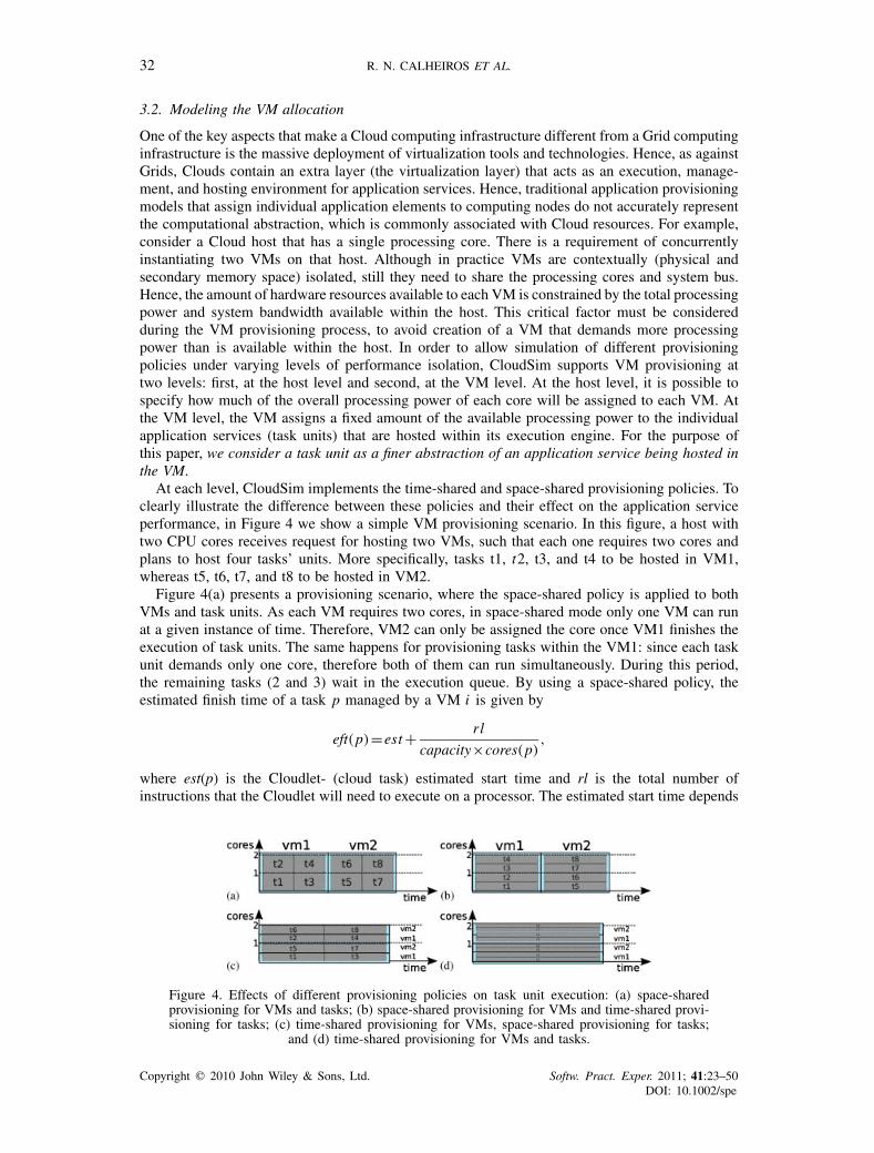
At each level, CloudSim implements the time-shared and space-shared provisioning policies. Toclearly illustrate the difference between these policies and their effect on the application serviceperformance, in Figure 4 we show a simple VM provisioning scenario. In this figure, a host withtwo CPU cores receives request for hosting two VMs, such that each one requires two cores andplans to host four tasks’ units. More specifically, tasks t1, t2, t3, and t4 to be hosted in VM1,whereas t5, t6, t7, and t8 to be hosted in VM2.
Figure 4(a) presents a provisioning scenario, where the space-shared policy is applied to bothVMs and task units. As each VM requires two cores, in space-shared mode only one VM can runat a given instance of time. Therefore, VM2 can only be assigned the core once VM1 finishes theexecution of task units. The same happens for provisioning tasks within the VM1: since each taskunit demands only one core, therefore both of them can run simultaneously. During this period,the remaining tasks (2 and 3) wait in the execution queue. By using a space-shared policy, theestimated finish time of a task p managed by a VM i is given by
eft(p)=est+ rl
capacity×cores(p),
where est(p) is the Cloudlet- (cloud task) estimated start time and rl is the total number ofinstructions that the Cloudlet will need to execute on a processor. The estimated start time depends
Figure 4. Effects of different provisioning policies on task unit execution: (a) space-sharedprovisioning for VMs and tasks; (b) space-shared provisioning for VMs and time-shared provi-sioning for tasks; (c) time-shared provisioning for VMs, space-shared provisioning for tasks;
and (d) time-shared provisioning for VMs and tasks.
Copyright q 2010 John Wiley & Sons, Ltd. Softw. Pract. Exper. 2011; 41:23–50DOI: 10.1002/spe
CLOUDSIM: A TOOLKIT 33
on the position of the Cloudlet in the execution queue, because the processing unit is usedexclusively (space-shared mode) by the Cloudlet. Cloudlets are put in the queue when there arefree processing cores available that can be assigned to the VM. In this policy, the total capacityof a host having np processing elements (PEs) is given by:
capacity=np∑i=1
cap(i)
np,
where cap(i) is the processing strength of individual elements.In Figure 4(b), a space-shared policy is applied for allocating VMs to hosts and a time-shared
policy forms the basis for allocating task units to processing core within a VM. Hence, during aVM lifetime, all the tasks assigned to it are dynamically context switched during their life cycle. Byusing a time-shared policy, the estimated finish time of a Cloudlet managed by a VM is given by
eft(p)=ct+ rl
capacity×cores(p),
where eft(p) is the estimated finish time, ct is the current simulation time, and cores(p) is thenumber of cores (PEs) required by the Cloudlet. In time-shared mode, multiple Cloudlets (taskunits) can simultaneously multi-task within a VM. In this case, we compute the total processingcapacity of Cloud host as
capacity=∑np
i=1 cap(i)
max(∑cloudlets
j=1 cores( j),np) ,
where cap(i) is the processing strength of individual elements.In Figure 4(c), a time-shared provisioning is used for VMs, whereas task units are provisioned
based on a space-shared policy. In this case, each VM receives a time slice on each processingcore, which then distributes the slices among task units on a space-shared basis. As the coresare shared, the amount of processing power available to a VM is variable. This is determined bycalculating VMs that are active on a host. As the task units are assigned based on a space-sharedpolicy, which means that at any given instance of time only one task will be actively using theprocessing core.
Finally, in Figure 4(d) a time-shared allocation is applied to both VMs and task units. Hence, theprocessing power is concurrently shared by the VMs and the shares of each VM are simultaneouslydivided among its task units. In this case, there are no queuing delays associated with task units.
3.3. Modeling the cloud market
Market is a crucial component of the Cloud computing ecosystem; it is necessary for regulatingCloud resource trading and online negotiations in a public Cloud computing model, where servicesare offered in a pay-as-you-go model. Hence, research studies that can accurately evaluate the cost-to-benefit ratio of emerging Cloud computing platforms are required. Furthermore, SaaS providersneed transparent mechanisms to discover various Cloud providers’ offerings (IaaS, PaaS, SaaS,and their associated costs). Thus, modeling of costs and economic policies are important aspectsto be considered when designing a Cloud simulator. The Cloud market is modeled based on amulti-layered (two layers) design. The first layer contains the economic of features related to theIaaS model such as cost per unit of memory, cost per unit of storage, and cost per unit of usedbandwidth. Cloud customers (SaaS providers) have to pay for the costs of memory and storagewhen they create and instantiate VMs, whereas the costs for network usage are only incurred inthe event of data transfer. The second layer models the cost metrics related to SaaS model. Costsat this layer are directly applicable to the task units (application service requests) that are servedby the application services. Hence, if a Cloud customer provisions a VM without an applicationservice (task unit), then they would only be charged for layer 1 resources (i.e. the costs of memoryand storage). This behavior may be changed or extended by CloudSim users.
Copyright q 2010 John Wiley & Sons, Ltd. Softw. Pract. Exper. 2011; 41:23–50DOI: 10.1002/spe
34 R. N. CALHEIROS ET AL.
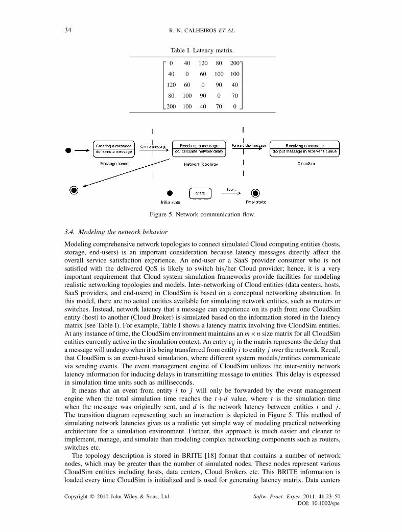
Table I. Latency matrix.
⎡⎢⎢⎢⎢⎢⎢⎢⎣
0 40 120 80 200
40 0 60 100 100
120 60 0 90 40
80 100 90 0 70
200 100 40 70 0
⎤⎥⎥⎥⎥⎥⎥⎥⎦
Figure 5. Network communication flow.
3.4. Modeling the network behavior
Modeling comprehensive network topologies to connect simulated Cloud computing entities (hosts,storage, end-users) is an important consideration because latency messages directly affect theoverall service satisfaction experience. An end-user or a SaaS provider consumer who is notsatisfied with the delivered QoS is likely to switch his/her Cloud provider; hence, it is a veryimportant requirement that Cloud system simulation frameworks provide facilities for modelingrealistic networking topologies and models. Inter-networking of Cloud entities (data centers, hosts,SaaS providers, and end-users) in CloudSim is based on a conceptual networking abstraction. Inthis model, there are no actual entities available for simulating network entities, such as routers orswitches. Instead, network latency that a message can experience on its path from one CloudSimentity (host) to another (Cloud Broker) is simulated based on the information stored in the latencymatrix (see Table I). For example, Table I shows a latency matrix involving five CloudSim entities.At any instance of time, the CloudSim environment maintains anm×n size matrix for all CloudSimentities currently active in the simulation context. An entry eij in the matrix represents the delay thata message will undergo when it is being transferred from entity i to entity j over the network. Recall,that CloudSim is an event-based simulation, where different system models/entities communicatevia sending events. The event management engine of CloudSim utilizes the inter-entity networklatency information for inducing delays in transmitting message to entities. This delay is expressedin simulation time units such as milliseconds.
It means that an event from entity i to j will only be forwarded by the event managementengine when the total simulation time reaches the t+d value, where t is the simulation timewhen the message was originally sent, and d is the network latency between entities i and j .The transition diagram representing such an interaction is depicted in Figure 5. This method ofsimulating network latencies gives us a realistic yet simple way of modeling practical networkingarchitecture for a simulation environment. Further, this approach is much easier and cleaner toimplement, manage, and simulate than modeling complex networking components such as routers,switches etc.
The topology description is stored in BRITE [18] format that contains a number of networknodes, which may be greater than the number of simulated nodes. These nodes represent variousCloudSim entities including hosts, data centers, Cloud Brokers etc. This BRITE information isloaded every time CloudSim is initialized and is used for generating latency matrix. Data centers
Copyright q 2010 John Wiley & Sons, Ltd. Softw. Pract. Exper. 2011; 41:23–50DOI: 10.1002/spe

CLOUDSIM: A TOOLKIT 35
and brokers are also required to be mapped as the network nodes. Further, any two CloudSimentities cannot be mapped to the same network node. Messages (events) sent by CloudSim entitiesare first processed by the NetworkTopology object that stores the network topology information.This object augments the latency information to the event and passes it on to the event managementengine for further processing. Let us consider an example scenario in which a data center is mappedto the first node and the Cloud broker to the fifth node in a sample BRITE network (see Table I).When a message is sent from the broker to the data center, the corresponding delay, stored at theelement (1, 5) of the latency matrix (200ms in this example), is added to the corresponding event.Therefore, the event management engine will take this delay into account before forwarding theevent to the destination entity. By using an external network description file (stored in BRITEformat), we allow reuse of same topology in different experiments. Moreover, the logical number ofnodes that are ambient in the configuration file can be greater than the number of actual simulatedentities; therefore, the network modeling approach does not compromise the scalability of theexperiments. For example, every time there are additional entities to be included in the simulation,they only need to be mapped to the BRITE nodes that are not currently mapped to any activeCloudSim entities. Hence, there will always exist a scope to grow the overall network size basedon application service and Cloud computing environment scenarios.
3.5. Modeling a federation of clouds
In order to federate or inter-network multiple clouds, there is a requirement for modeling aCloudCoordinator entity. This entity is responsible not only for communicating with other datacenters and end-users in the simulation environment, but also for monitoring and managing theinternal state of a data center entity. The information received as part of the monitoring process, thatis active throughout the simulation period, is utilized for making decisions related to inter-cloudprovisioning. Note that no software object offering similar functionality to the CloudCoordinator isoffered by the existing providers, such as Amazon, Azure, or Google App Engine presently. Hence,if a developer of a real-world Cloud system wants to federate services from multiple clouds, theywill be required to develop a CloudCoordinator component. By having such an entity to managethe federation of Cloud-based data centers, aspects related to communication and negotiation withforeign entities are isolated from the data center core. Therefore, by providing such an entityamong its core objects, CloudSim helps Cloud developers in speeding up their application serviceperformance testing.
The two fundamental aspects that must be handled when simulating a federation of cloudsinclude: communication and monitoring. The first aspect (communication) is handled by thedata center through the standard event-based messaging process. The second aspect (data centermonitoring) is carried out by the CloudCoordinator. Every data center in CloudSim needs toinstantiate this entry in order to make itself a part of Cloud federation. The CloudCoordinatortriggers the inter-cloud load adjustment process based on the state of the data center. The specificset of events that affect the adjustment are implemented via a specific sensor entity. Each sensorentity implements a particular parameter (such as under provisioning, over provisioning, and SLAviolation) related to the data center. For enabling online monitoring of a data center host, a sensorthat keeps track of the host status (utilization, heating) is attached with the CloudCoordinator. Atevery monitoring step, the CloudCoordinator queries the sensor. If a certain pre-configured thresholdis achieved, the CloudCoordinator starts the communication with its peers (other CloudCoordinatorsin the federation) for possible load-shredding. The negotiation protocol, load-shredding policy, andcompensation mechanism can be easily extended to suit a particular research study.
3.6. Modeling dynamic workloads
Software developers and third-party service providers often deploy applications that exhibitdynamic behavior [7] in terms of workload patterns, availability, and scalability requirements.Typically, Cloud computing thrives on highly varied and elastic services and infrastructuredemands. Leading Cloud vendors, including Amazon and Azure, expose VM containers/templatesto host a range of SaaS types and provide SaaS providers with the notion of unlimited resource
Copyright q 2010 John Wiley & Sons, Ltd. Softw. Pract. Exper. 2011; 41:23–50DOI: 10.1002/spe
36 R. N. CALHEIROS ET AL.
pool that can be leased on the fly with requested configurations. Pertaining to the aforementionedfacts, it is an important requirement that any simulation environment supports the modeling ofdynamic workload patterns driven by application or SaaS models. In order to allow simulationof dynamic behaviors within CloudSim, we have made a number of extensions to the existingframework, in particular to the Cloudlet entity. We have designed an additional simulation entitywithin CloudSim, which is referred to as the Utilization Model that exposes methods and variablesfor defining the resource and VM-level requirements of a SaaS application at the instance ofdeployment. In the CloudSim framework, Utilization Model is an abstract class that must beextended for implementing a workload pattern required to model the application’s resourcedemand. CloudSim users are required to override the method, getUtilization(), whose input typeis discrete time parameter and return type is percentage of computational resource required by theCloudlet.
Another important requirement for Cloud computing environments is to ensure that the agreedSLA in terms of QoS parameters, such as availability, reliability, and throughput, are deliveredto the applications. Although modern virtualization technologies can ensure performance isolationbetween applications running on different VMs, there still exists scope for developing methodolo-gies at the VM provisioning level that can further improve resource utilization. Lack of intelligentmethodologies for VM provisioning raises a risk that all VMs deployed on a single host maynot get the adequate amount of processor share that is essential for fulfilling the agreed SLAs.This may lead to performance loss in terms of response time, time outs, or failures in the worstcase. The resource provider must take into account such behaviors and initiate necessary actionsto minimize the effect on the application performance. To simulate such behavior, the SLA modelcan either be defined as fully allocating the requested amount of resources or allowing flexibleresource allocations up to a specific rate as long as the agreed SLA can be delivered (e.g. allowingthe CPU share to be 10% below the requested amount). CloudSim supports modeling of theaforementioned SLA violation scenarios. Moreover, it is possible to define particular SLA-awarepolicies describing how the available capacity is distributed among competing VMs in case of alack of resources. The number of SLA violation events as well as the amount of resource that wasrequested but not allocated can be accounted for by CloudSim.
3.7. Modeling data center power consumption
Cloud computing environments are built upon an inter-connected network of a large number(hundreds-of-thousands) of computing and storage hosts for delivering on-demand services (IaaS,PaaS, and SaaS). Such infrastructures in conjunction with a cooling system may consume enor-mous amount of electrical power resulting in high operational costs [19]. Lack of energy-consciousprovisioning techniques may lead to overheating of Cloud resources (compute and storage servers)in case of high loads. This in turn may result in reduced system reliability and lifespan of devices.Another related issue is the carbon dioxide (CO2) emission that is detrimental to the physical envi-ronment due to its contribution in the greenhouse effect. All these problems require the developmentof efficient energy-conscious provisioning policies at resource, VM, and application level.
To this end, the CloudSim framework provides basic models and entities to validate and evaluateenergy-conscious provisioning of techniques/algorithms. We have made a number of extensions toCloudSim for facilitating the above, such as extending the PE object to include an additional PowerModel object for managing power consumption on a per Cloud host basis. To support modelingand simulation of different power consumption models and power management techniques such asDynamic Voltage and Frequency Scaling (DVFS), we provide an abstract implementation calledPowerModel. This abstract class should be extended for simulating custom power consumptionmodel of a PE. CloudSim users need to override the method getPower() of this class, whoseinput parameter is the current utilization metric for Cloud host and return parameter is the currentpower consumption value. This capability enables the creation of energy-conscious provisioningpolicies that require real-time knowledge of power consumption by Cloud system components.Furthermore, it enables the accounting of the total energy consumed by the system during thesimulation period.
Copyright q 2010 John Wiley & Sons, Ltd. Softw. Pract. Exper. 2011; 41:23–50DOI: 10.1002/spe
CLOUDSIM: A TOOLKIT 37
3.8. Modeling dynamic entities creation
Clouds offer a pool of software services and hardware servers on an unprecedented scale, whichgives businesses a unique ability to handle the temporal variation in demand through dynamicprovisioning or de-provisioning of capabilities from clouds. Actual usage patterns of many enter-prise services (business applications) vary with time, most of the time in an unpredictable way.This leads to the necessity for Cloud providers to deal with customers who can enter or leave thesystem at any time. CloudSim allows such simulation scenarios by supporting dynamic creationof different kinds of entities. Apart from the dynamic creation of user and broker entities, it isalso possible to add and remove data center entities at run-time. This functionality might be usefulfor simulating dynamic environment where system components can join, fail, or leave the systemrandomly. After creation, new entities automatically register themselves in the Cloud InformationService (CIS) to enable dynamic resource discovery.
4. DESIGN AND IMPLEMENTATION OF CLOUDSIM
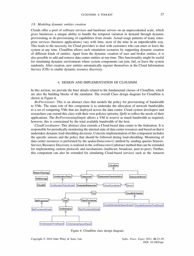
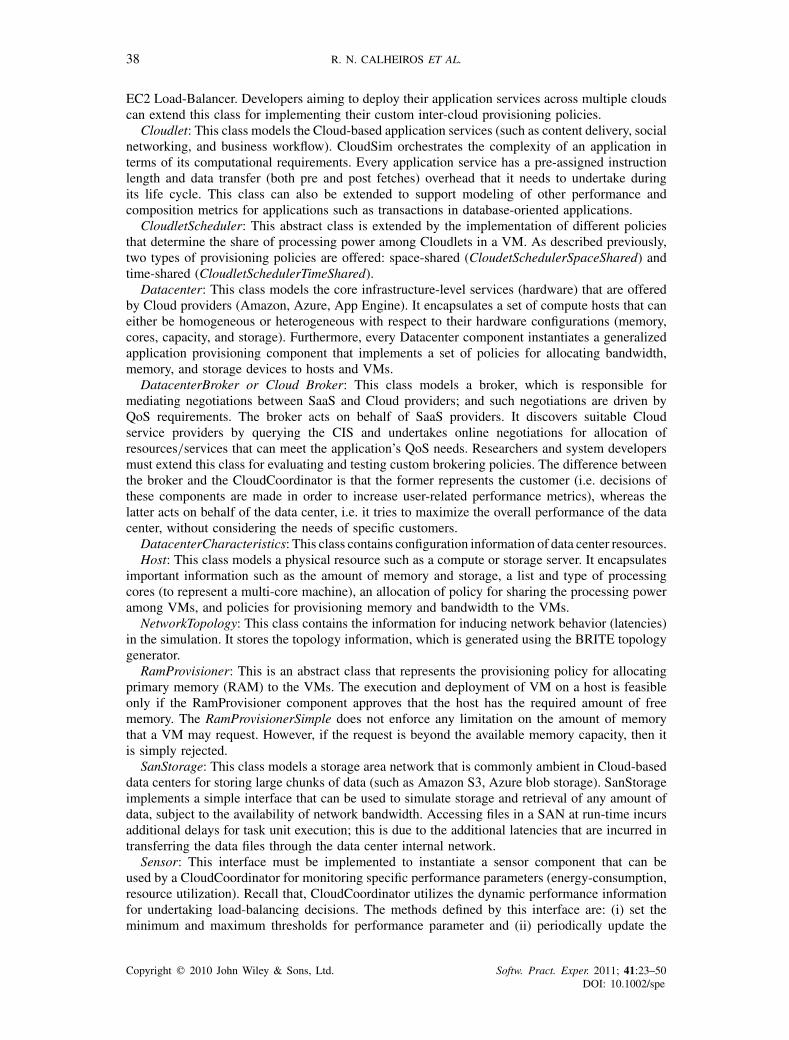
In this section, we provide the finer details related to the fundamental classes of CloudSim, whichare also the building blocks of the simulator. The overall Class design diagram for CloudSim isshown in Figure 6.
BwProvisioner: This is an abstract class that models the policy for provisioning of bandwidthto VMs. The main role of this component is to undertake the allocation of network bandwidthsto a set of competing VMs that are deployed across the data center. Cloud system developers andresearchers can extend this class with their own policies (priority, QoS) to reflect the needs of theirapplications. The BwProvisioningSimple allows a VM to reserve as much bandwidth as required;however, this is constrained by the total available bandwidth of the host.
CloudCoordinator: This abstract class extends a Cloud-based data center to the federation. It isresponsible for periodically monitoring the internal state of data center resources and based on that itundertakes dynamic load-shredding decisions. Concrete implementation of this component includesthe specific sensors and the policy that should be followed during load-shredding. Monitoring ofdata center resources is performed by the updateDatacenter() method by sending queries Sensors.Service/Resource Discovery is realized in the setDatacenter()abstract method that can be extendedfor implementing custom protocols and mechanisms (multicast, broadcast, peer-to-peer). Further,this component can also be extended for simulating Cloud-based services such as the Amazon
Figure 6. CloudSim class design diagram.
Copyright q 2010 John Wiley & Sons, Ltd. Softw. Pract. Exper. 2011; 41:23–50DOI: 10.1002/spe
38 R. N. CALHEIROS ET AL.
EC2 Load-Balancer. Developers aiming to deploy their application services across multiple cloudscan extend this class for implementing their custom inter-cloud provisioning policies.
Cloudlet: This class models the Cloud-based application services (such as content delivery, socialnetworking, and business workflow). CloudSim orchestrates the complexity of an application interms of its computational requirements. Every application service has a pre-assigned instructionlength and data transfer (both pre and post fetches) overhead that it needs to undertake duringits life cycle. This class can also be extended to support modeling of other performance andcomposition metrics for applications such as transactions in database-oriented applications.
CloudletScheduler: This abstract class is extended by the implementation of different policiesthat determine the share of processing power among Cloudlets in a VM. As described previously,two types of provisioning policies are offered: space-shared (CloudetSchedulerSpaceShared) andtime-shared (CloudletSchedulerTimeShared).
Datacenter: This class models the core infrastructure-level services (hardware) that are offeredby Cloud providers (Amazon, Azure, App Engine). It encapsulates a set of compute hosts that caneither be homogeneous or heterogeneous with respect to their hardware configurations (memory,cores, capacity, and storage). Furthermore, every Datacenter component instantiates a generalizedapplication provisioning component that implements a set of policies for allocating bandwidth,memory, and storage devices to hosts and VMs.
DatacenterBroker or Cloud Broker: This class models a broker, which is responsible formediating negotiations between SaaS and Cloud providers; and such negotiations are driven byQoS requirements. The broker acts on behalf of SaaS providers. It discovers suitable Cloudservice providers by querying the CIS and undertakes online negotiations for allocation ofresources/services that can meet the application’s QoS needs. Researchers and system developersmust extend this class for evaluating and testing custom brokering policies. The difference betweenthe broker and the CloudCoordinator is that the former represents the customer (i.e. decisions ofthese components are made in order to increase user-related performance metrics), whereas thelatter acts on behalf of the data center, i.e. it tries to maximize the overall performance of the datacenter, without considering the needs of specific customers.
DatacenterCharacteristics: This class contains configuration information of data center resources.Host: This class models a physical resource such as a compute or storage server. It encapsulates
important information such as the amount of memory and storage, a list and type of processingcores (to represent a multi-core machine), an allocation of policy for sharing the processing poweramong VMs, and policies for provisioning memory and bandwidth to the VMs.
NetworkTopology: This class contains the information for inducing network behavior (latencies)in the simulation. It stores the topology information, which is generated using the BRITE topologygenerator.
RamProvisioner: This is an abstract class that represents the provisioning policy for allocatingprimary memory (RAM) to the VMs. The execution and deployment of VM on a host is feasibleonly if the RamProvisioner component approves that the host has the required amount of freememory. The RamProvisionerSimple does not enforce any limitation on the amount of memorythat a VM may request. However, if the request is beyond the available memory capacity, then itis simply rejected.
SanStorage: This class models a storage area network that is commonly ambient in Cloud-baseddata centers for storing large chunks of data (such as Amazon S3, Azure blob storage). SanStorageimplements a simple interface that can be used to simulate storage and retrieval of any amount ofdata, subject to the availability of network bandwidth. Accessing files in a SAN at run-time incursadditional delays for task unit execution; this is due to the additional latencies that are incurred intransferring the data files through the data center internal network.
Sensor: This interface must be implemented to instantiate a sensor component that can beused by a CloudCoordinator for monitoring specific performance parameters (energy-consumption,resource utilization). Recall that, CloudCoordinator utilizes the dynamic performance informationfor undertaking load-balancing decisions. The methods defined by this interface are: (i) set theminimum and maximum thresholds for performance parameter and (ii) periodically update the
Copyright q 2010 John Wiley & Sons, Ltd. Softw. Pract. Exper. 2011; 41:23–50DOI: 10.1002/spe
CLOUDSIM: A TOOLKIT 39
measurement. This class can be used to model the real-world services offered by leading Cloudproviders such as Amazon’s CloudWatch and Microsoft Azure’s FabricController. One data centermay instantiate one or more Sensors, each one responsible for monitoring a specific data centerperformance parameter.
Vm: This class models a VM, which is managed and hosted by a Cloud host component. EveryVM component has access to a component that stores the following characteristics related to aVM: accessible memory, processor, storage size, and the VM’s internal provisioning policy that isextended from an abstract component called the CloudletScheduler.
VmmAllocationPolicy: This abstract class represents a provisioning policy that a VM Monitorutilizes for allocating VMs to hosts. The chief functionality of the VmmAllocationPolicy is to selectthe available host in a data center that meets the memory, storage, and availability requirement fora VM deployment.
VmScheduler: This is an abstract class implemented by a Host component that models the policies(space-shared, time-shared) required for allocating processor cores to VMs. The functionalities ofthis class can easily be overridden to accommodate application-specific processor sharing policies.
4.1. CloudSim core simulation framework
As discussed previously, GridSim is one of the building blocks of CloudSim. However, GridSimuses the SimJava library as a framework for event handling and inter-entity message passing.SimJava has several limitations that impose some restrictions with regard to creation of scalablesimulation environments such as:
• It does not allow resetting the simulation programmatically at run-time.• It does not support creation of new simulation entity at run-time (once simulation has beeninitiated).
• Multi-threaded nature of SimJava leads to performance overhead with the increase in systemsize. The performance degradation is caused by the excessive context switching betweenthreads.
• Multi-threading brings additional complexity with regard to system debugging.
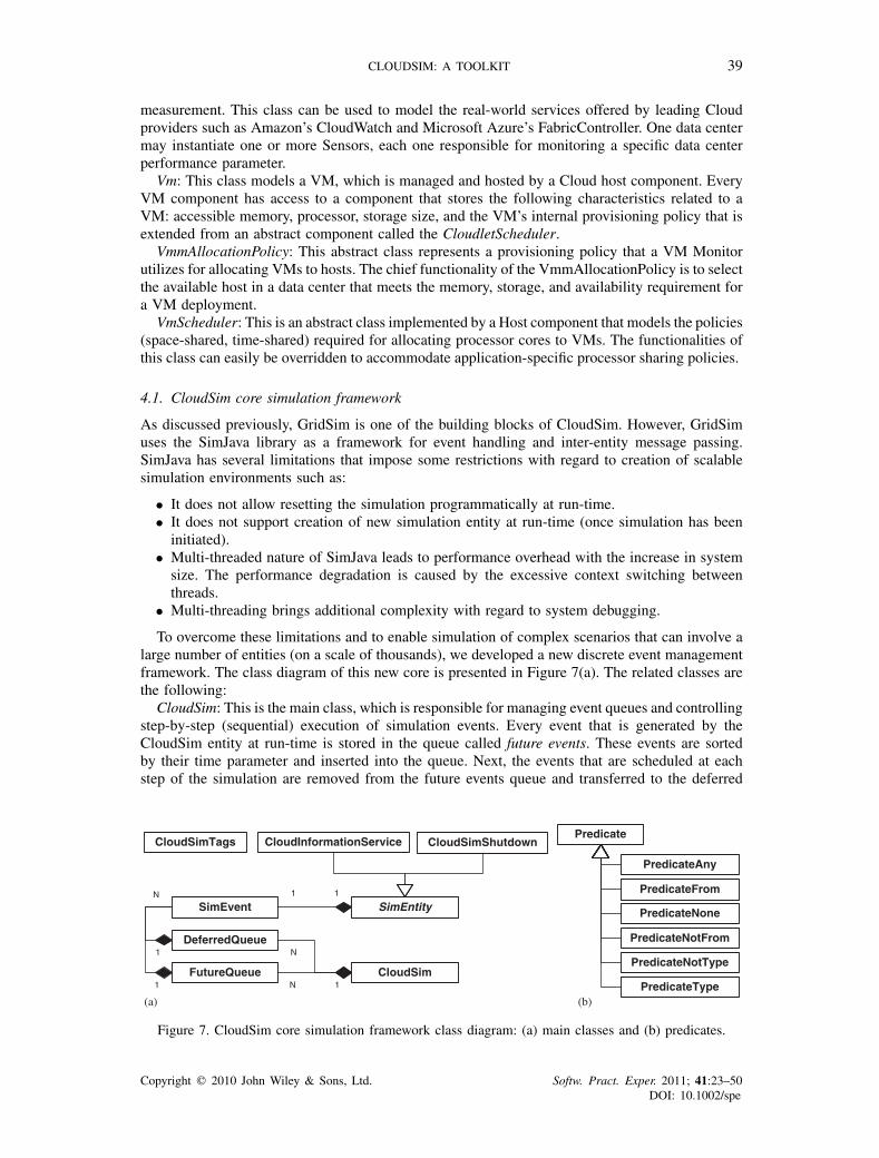
To overcome these limitations and to enable simulation of complex scenarios that can involve alarge number of entities (on a scale of thousands), we developed a new discrete event managementframework. The class diagram of this new core is presented in Figure 7(a). The related classes arethe following:
CloudSim: This is the main class, which is responsible for managing event queues and controllingstep-by-step (sequential) execution of simulation events. Every event that is generated by theCloudSim entity at run-time is stored in the queue called future events. These events are sortedby their time parameter and inserted into the queue. Next, the events that are scheduled at eachstep of the simulation are removed from the future events queue and transferred to the deferred
CloudSim
DeferredQueue
FutureQueue
SimEntitySimEvent
CloudSimShutdownCloudInformationService
11
CloudSimTags
N 1
N1
1
N
Predicate
PredicateAny
PredicateFrom
PredicateNone
PredicateNotFrom
PredicateNotType
PredicateType(a) (b)
Figure 7. CloudSim core simulation framework class diagram: (a) main classes and (b) predicates.
Copyright q 2010 John Wiley & Sons, Ltd. Softw. Pract. Exper. 2011; 41:23–50DOI: 10.1002/spe
40 R. N. CALHEIROS ET AL.
event queue. Following this, an event processing method is invoked for each entity, which choosesevents from the deferred event queue and performs appropriate actions. Such an organization allowsflexible management of simulation and provides the following powerful capabilities:
• Deactivation (holding) of entities.• Context switching of entities between different states (e.g. waiting to active). Pausing andresuming the process of simulation.
• Creation of new entities at run-time.• Aborting and restarting simulation at run-time.
DeferredQueue: This class implements the deferred event queue used by CloudSim.FutureQueue: This class implements the future event queue accessed by CloudSim.CloudInformationService: A CIS is an entity that provides resource registration, indexing, and
discovering capabilities. CIS supports two basic primitives: (i) publish(), which allows entities toregister themselves with CIS and (ii) search(), which allows entities such as CloudCoordinatorand Brokers in discovering status and endpoint contact address of other entities. This entity alsonotifies the (other?) entities about the end of simulation.
SimEntity: This is an abstract class, which represents a simulation entity that is able to sendmessages to other entities and process received messages as well as fire and handle events. Allentities must extend this class and override its three core methods: startEntity(), processEvent() andshutdownEntity(), which define actions for entity initialization, processing of events, and entitydestruction, respectively. SimEntity class provides the ability to schedule new events and sendmessages to other entities, where network delay is calculated according to the BRITE model. Oncecreated, entities automatically register with CIS.
CloudSimTags. This class contains various static event/command tags that indicate the type ofaction that needs to be undertaken by CloudSim entities when they receive or send events.
SimEvent: This entity represents a simulation event that is passed between two or more entities.SimEvent stores the following information about an event: type, init time, time at which the eventshould occur, finish time, time at which the event should be delivered to its destination entity, IDsof the source(s?) and destination entities, tag of the event, and data that have to be passed to thedestination entity.
CloudSimShutdown: This is an entity that waits for the termination of all end-user and brokerentities, and then signals the end of simulation to CIS.
Predicate: Predicates are used for selecting events from the deferred queue. This is an abstractclass and must be extended to create a new predicate. Some standard predicates are provided thatare presented in Figure 7(b).
PredicateAny: This class represents a predicate that matches any event on the deferred eventqueue. There is a publicly accessible instance of this predicate in the CloudSim class, calledCloudSim.SIM ANY, and hence no new instances need to be created.
PredicateFrom: This class represents a predicate that selects events fired by specific entities.PredicateNone: This represents a predicate that does not match any event on the deferred event
queue. There is a publicly accessible static instance of this predicate in the CloudSim class, calledCloudSim.SIM NONE; hence, the users are not needed to create any new instances of this class.
PredicateNotFrom: This class represents a predicate that selects events that have not been sentby specific entities.
PredicateNotType: This class represents a predicate to select events that do not match specifictags.
PredicateType: This class represents a predicate to select events with specific tags.
4.2. Data center internal processing
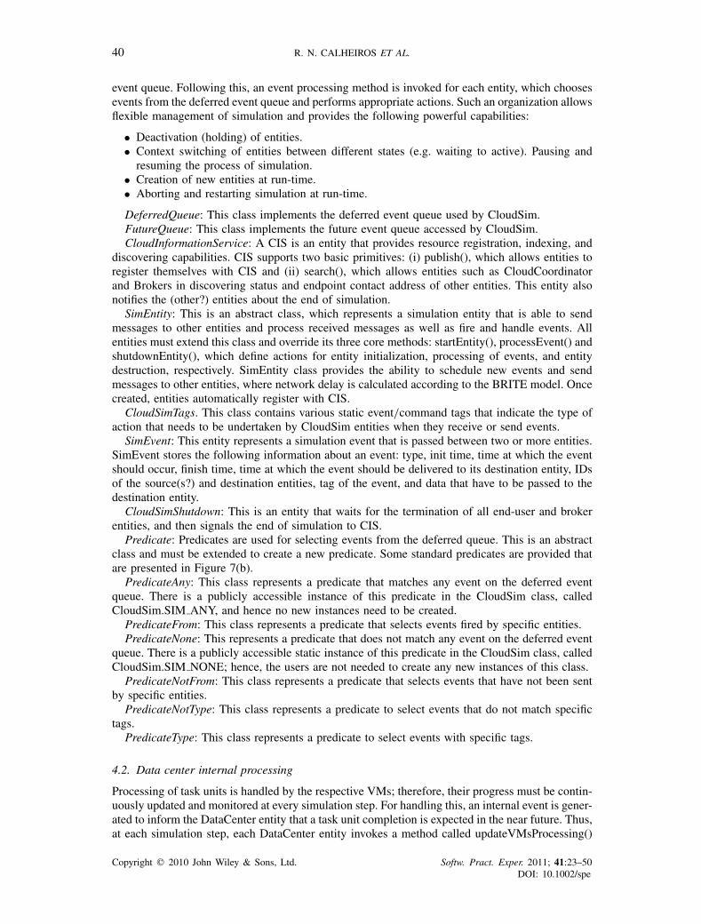
Processing of task units is handled by the respective VMs; therefore, their progress must be contin-uously updated and monitored at every simulation step. For handling this, an internal event is gener-ated to inform the DataCenter entity that a task unit completion is expected in the near future. Thus,at each simulation step, each DataCenter entity invokes a method called updateVMsProcessing()
Copyright q 2010 John Wiley & Sons, Ltd. Softw. Pract. Exper. 2011; 41:23–50DOI: 10.1002/spe
CLOUDSIM: A TOOLKIT 41
Figure 8. Cloudlet processing update process.
for every host that it manages. Following this, the contacted VMs update processing of currentlyactive tasks with the host. The input parameter type for this method is the current simulation timeand the return parameter type is the next expected completion time of a task currently running inone of the VMs on that host. The next internal event time is the least time among all the finishtimes, which are returned by the hosts.
At the host level, invocation of updateVMsProcessing() triggers an updateCloudletsProcessing()method that directs every VM to update its tasks unit status (finish, suspended, executing) withthe Datacenter entity. This method implements a similar logic as described previously for updat-eVMsProcessing() but at the VM level. Once this method is called, VMs return the next expectedcompletion time of the task units currently managed by them. The least completion time amongall the computed values is sent to the Datacenter entity. As a result, completion times are keptin a queue that is queried by Datacenter after each event processing step. The completed taskswaiting in the finish queue that are directly returned concern CloudBroker or CloudCoordinator.This process is depicted in Figure 8 in the form of a sequence diagram.
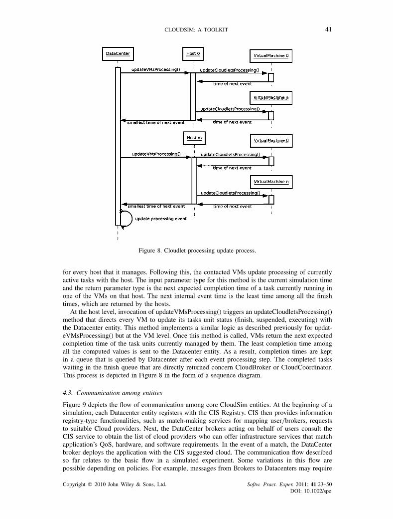
4.3. Communication among entities
Figure 9 depicts the flow of communication among core CloudSim entities. At the beginning of asimulation, each Datacenter entity registers with the CIS Registry. CIS then provides informationregistry-type functionalities, such as match-making services for mapping user/brokers, requeststo suitable Cloud providers. Next, the DataCenter brokers acting on behalf of users consult theCIS service to obtain the list of cloud providers who can offer infrastructure services that matchapplication’s QoS, hardware, and software requirements. In the event of a match, the DataCenterbroker deploys the application with the CIS suggested cloud. The communication flow describedso far relates to the basic flow in a simulated experiment. Some variations in this flow arepossible depending on policies. For example, messages from Brokers to Datacenters may require
Copyright q 2010 John Wiley & Sons, Ltd. Softw. Pract. Exper. 2011; 41:23–50DOI: 10.1002/spe
42 R. N. CALHEIROS ET AL.
Figure 9. Simulation data flow.
a confirmation from other parts of the Datacenter, about the execution of an action, or about themaximum number of VMs that a user can create.
5. EXPERIMENTS AND EVALUATION
In this section, we present the experiments and evaluation that we undertook in order to quantifythe efficiency of CloudSim in modeling and simulation of Cloud computing environments.
5.1. CloudSim: scalability and overhead evaluation
The first tests that we present here are aimed at analyzing the overhead and scalability of memoryusage, and the overall efficiency of CloudSim. The tests were conducted on a machine that hadtwo Intel Xeon Quad-core 2.27GHz and 16GB of RAM memory. All of these hardware resourceswere made available to a VM running Ubuntu 8.04 that was used for running the tests.
The test simulation environment setup for measuring the overhead and memory usage byCloudSim included DataCenterBroker and DataCenter (hosting a number of machines) entities.In the first test, all the machines were hosted within a single data center. Then for the next test,the machines were symmetrically distributed across two data centers. The number of hosts inboth the experiments varied from 1000 to 1 000 000. Each experiment was repeated 30 times.For the memory test, the total physical memory usage required for fully instantiating and loadingthe CloudSim environment was profiled. For the overhead test, the total delay in instantiating thesimulation environment was computed as the time difference between the following events: (i) thetime at which the run-time environment (Java VM) is instructed to load the CloudSim framework;and (ii) the instance at which CloudSim’s entities are fully initialized and are ready to processevents.
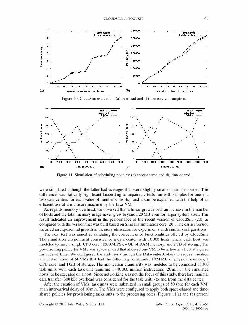
Figure 10(a) presents the average amount of time that was required for setting up simulation asa function of several hosts considered in the experiment. Figure 10(b) plots the amount of memorythat was required for successfully conducting the tests. The results showed that the overheaddoes not grow linearly with the system size. Instead, we observed that it grows in steps when aspecific number of hosts were used in the experiment. The obtained results showed that the time toinstantiate an experiment setup with 1 million hosts is around 12 s. These observations proved thatCloudSim is capable of supporting a large-scale simulation environment with little or no overheadas regard initialization time and memory consumption. Hence, CloudSim offers significant benefitsas a performance testing platform when compared with the real-world Cloud offerings. It is almostimpossible to compute the time and economic overhead that would incur in setting up such alarge-scale test environment on Cloud platforms (Amazon EC2, Azure). The results showed almostthe same behavior under different system sizes (Cloud infrastructure deployed across one or twodata centers). The same behavior was observed for the cases when only one and two data centers
Copyright q 2010 John Wiley & Sons, Ltd. Softw. Pract. Exper. 2011; 41:23–50DOI: 10.1002/spe
CLOUDSIM: A TOOLKIT 43
Figure 10. CloudSim evaluation: (a) overhead and (b) memory consumption.
Figure 11. Simulation of scheduling policies: (a) space-shared and (b) time-shared.
were simulated although the latter had averages that were slightly smaller than the former. Thisdifference was statically significant (according to unpaired t-tests run with samples for one andtwo data centers for each value of number of hosts), and it can be explained with the help of anefficient use of a multicore machine by the Java VM.
As regards memory overhead, we observed that a linear growth with an increase in the numberof hosts and the total memory usage never grew beyond 320MB even for larger system sizes. Thisresult indicated an improvement in the performance of the recent version of CloudSim (2.0) ascompared with the version that was built based on SimJava simulation core [20]. The earlier versionincurred an exponential growth in memory utilization for experiments with similar configurations.
The next test was aimed at validating the correctness of functionalities offered by CloudSim.The simulation environment consisted of a data center with 10 000 hosts where each host wasmodeled to have a single CPU core (1200MIPS), 4GB of RAM memory, and 2 TB of storage. Theprovisioning policy for VMs was space-shared that allowed one VM to be active in a host at a giveninstance of time. We configured the end-user (through the DatacenterBroker) to request creationand instantiation of 50VMs that had the following constraints: 1024MB of physical memory, 1CPU core, and 1GB of storage. The application granularity was modeled to be composed of 300task units, with each task unit requiring 1 440 000 million instructions (20min in the simulatedhosts) to be executed on a host. Since networking was not the focus of this study, therefore minimaldata transfer (300 kB) overhead was considered for the task units (to and from the data center).
After the creation of VMs, task units were submitted in small groups of 50 (one for each VM)at an inter-arrival delay of 10min. The VMs were configured to apply both space-shared and time-shared policies for provisioning tasks units to the processing cores. Figures 11(a) and (b) present
Copyright q 2010 John Wiley & Sons, Ltd. Softw. Pract. Exper. 2011; 41:23–50DOI: 10.1002/spe
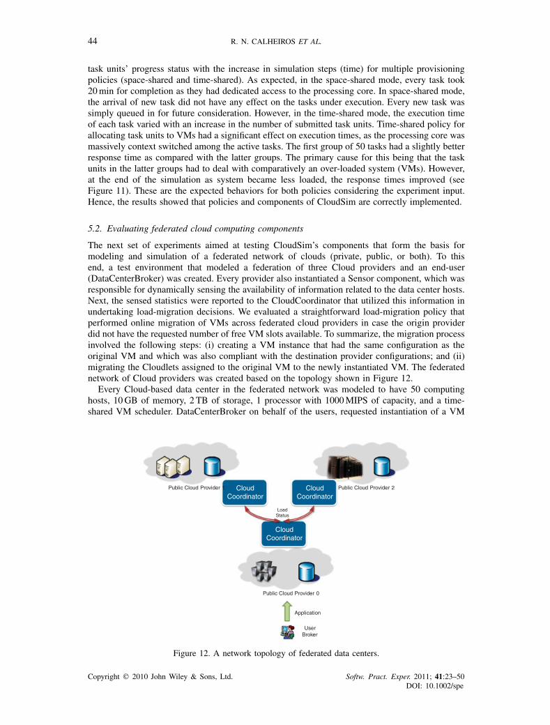
44 R. N. CALHEIROS ET AL.
task units’ progress status with the increase in simulation steps (time) for multiple provisioningpolicies (space-shared and time-shared). As expected, in the space-shared mode, every task took20min for completion as they had dedicated access to the processing core. In space-shared mode,the arrival of new task did not have any effect on the tasks under execution. Every new task wassimply queued in for future consideration. However, in the time-shared mode, the execution timeof each task varied with an increase in the number of submitted task units. Time-shared policy forallocating task units to VMs had a significant effect on execution times, as the processing core wasmassively context switched among the active tasks. The first group of 50 tasks had a slightly betterresponse time as compared with the latter groups. The primary cause for this being that the taskunits in the latter groups had to deal with comparatively an over-loaded system (VMs). However,at the end of the simulation as system became less loaded, the response times improved (seeFigure 11). These are the expected behaviors for both policies considering the experiment input.Hence, the results showed that policies and components of CloudSim are correctly implemented.
5.2. Evaluating federated cloud computing components
The next set of experiments aimed at testing CloudSim’s components that form the basis formodeling and simulation of a federated network of clouds (private, public, or both). To thisend, a test environment that modeled a federation of three Cloud providers and an end-user(DataCenterBroker) was created. Every provider also instantiated a Sensor component, which wasresponsible for dynamically sensing the availability of information related to the data center hosts.Next, the sensed statistics were reported to the CloudCoordinator that utilized this information inundertaking load-migration decisions. We evaluated a straightforward load-migration policy thatperformed online migration of VMs across federated cloud providers in case the origin providerdid not have the requested number of free VM slots available. To summarize, the migration processinvolved the following steps: (i) creating a VM instance that had the same configuration as theoriginal VM and which was also compliant with the destination provider configurations; and (ii)migrating the Cloudlets assigned to the original VM to the newly instantiated VM. The federatednetwork of Cloud providers was created based on the topology shown in Figure 12.
Every Cloud-based data center in the federated network was modeled to have 50 computinghosts, 10GB of memory, 2 TB of storage, 1 processor with 1000MIPS of capacity, and a time-shared VM scheduler. DataCenterBroker on behalf of the users, requested instantiation of a VM
Public Cloud Provider 1 Public Cloud Provider 2
Public Cloud Provider 0
CloudCoordinator
CloudCoordinator
CloudCoordinator
LoadStatus
User Broker
Application
Figure 12. A network topology of federated data centers.
Copyright q 2010 John Wiley & Sons, Ltd. Softw. Pract. Exper. 2011; 41:23–50DOI: 10.1002/spe
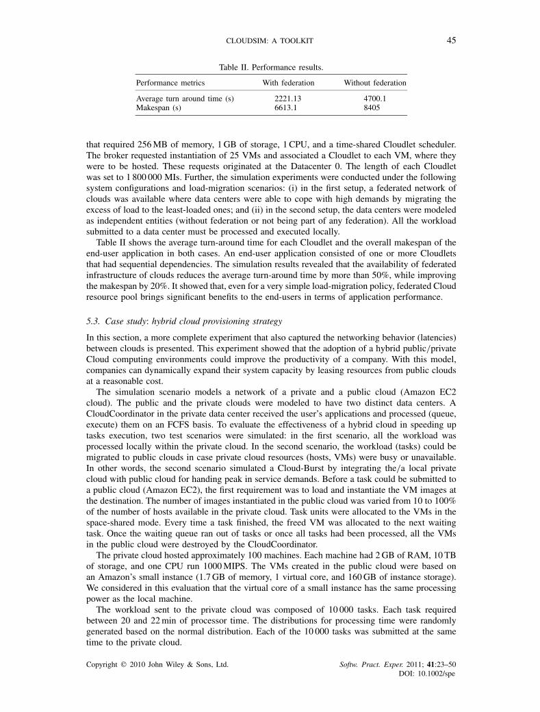
CLOUDSIM: A TOOLKIT 45
Table II. Performance results.
Performance metrics With federation Without federation
Average turn around time (s) 2221.13 4700.1Makespan (s) 6613.1 8405
that required 256MB of memory, 1GB of storage, 1 CPU, and a time-shared Cloudlet scheduler.The broker requested instantiation of 25 VMs and associated a Cloudlet to each VM, where theywere to be hosted. These requests originated at the Datacenter 0. The length of each Cloudletwas set to 1 800 000 MIs. Further, the simulation experiments were conducted under the followingsystem configurations and load-migration scenarios: (i) in the first setup, a federated network ofclouds was available where data centers were able to cope with high demands by migrating theexcess of load to the least-loaded ones; and (ii) in the second setup, the data centers were modeledas independent entities (without federation or not being part of any federation). All the workloadsubmitted to a data center must be processed and executed locally.
Table II shows the average turn-around time for each Cloudlet and the overall makespan of theend-user application in both cases. An end-user application consisted of one or more Cloudletsthat had sequential dependencies. The simulation results revealed that the availability of federatedinfrastructure of clouds reduces the average turn-around time by more than 50%, while improvingthe makespan by 20%. It showed that, even for a very simple load-migration policy, federated Cloudresource pool brings significant benefits to the end-users in terms of application performance.
5.3. Case study: hybrid cloud provisioning strategy
In this section, a more complete experiment that also captured the networking behavior (latencies)between clouds is presented. This experiment showed that the adoption of a hybrid public/privateCloud computing environments could improve the productivity of a company. With this model,companies can dynamically expand their system capacity by leasing resources from public cloudsat a reasonable cost.
The simulation scenario models a network of a private and a public cloud (Amazon EC2cloud). The public and the private clouds were modeled to have two distinct data centers. ACloudCoordinator in the private data center received the user’s applications and processed (queue,execute) them on an FCFS basis. To evaluate the effectiveness of a hybrid cloud in speeding uptasks execution, two test scenarios were simulated: in the first scenario, all the workload wasprocessed locally within the private cloud. In the second scenario, the workload (tasks) could bemigrated to public clouds in case private cloud resources (hosts, VMs) were busy or unavailable.In other words, the second scenario simulated a Cloud-Burst by integrating the/a local privatecloud with public cloud for handing peak in service demands. Before a task could be submitted toa public cloud (Amazon EC2), the first requirement was to load and instantiate the VM images atthe destination. The number of images instantiated in the public cloud was varied from 10 to 100%of the number of hosts available in the private cloud. Task units were allocated to the VMs in thespace-shared mode. Every time a task finished, the freed VM was allocated to the next waitingtask. Once the waiting queue ran out of tasks or once all tasks had been processed, all the VMsin the public cloud were destroyed by the CloudCoordinator.
The private cloud hosted approximately 100 machines. Each machine had 2GB of RAM, 10TBof storage, and one CPU run 1000MIPS. The VMs created in the public cloud were based onan Amazon’s small instance (1.7GB of memory, 1 virtual core, and 160GB of instance storage).We considered in this evaluation that the virtual core of a small instance has the same processingpower as the local machine.
The workload sent to the private cloud was composed of 10 000 tasks. Each task requiredbetween 20 and 22min of processor time. The distributions for processing time were randomlygenerated based on the normal distribution. Each of the 10 000 tasks was submitted at the sametime to the private cloud.
Copyright q 2010 John Wiley & Sons, Ltd. Softw. Pract. Exper. 2011; 41:23–50DOI: 10.1002/spe

46 R. N. CALHEIROS ET AL.
Table III. Cost and performance of several public/private cloud strategies.
Strategy Makespan (s) Cloud cost (U$)
Private only 127155.77 0.00Public 10% 115902.34 32.60Public 20% 106222.71 60.00Public 30% 98195.57 83.30Public 40% 91088.37 103.30Public 50% 85136.78 120.00Public 60% 79776.93 134.60Public 70% 75195.84 147.00Public 80% 70967.24 160.00Public 90% 67238.07 171.00Public 100% 64192.89 180.00
Table III shows the makespan of the tasks that were achieved for different combinations ofprivate and public cloud resources. In the third column of the table, we quantify the overall costof the services. The pricing policy was designed based on Amazon’s small instances (U$ 0.10 perinstance per hour) business model. It means that the cost per instance is charged hourly. Thus, ifan instance runs during 1 h and 1min, the amount for 2 h (U$ 0.20) will be charged.
As expected, with an increase in the size of the resource pool that was available to task provi-sioning, the overall makespan of tasks reduced. However, the cost associated with the processingalso increased, with an increase in % of public cloud resource. Nevertheless, we found that theincreased cost offered significant gains in terms of improved makespan. Overall, it was alwayscheaper to rent resources from public clouds for handling sudden peaks in demands as comparedwith buying or installing private infrastructures.
5.4. Case study: energy-conscious management of data center
In order to test the capability of CloudSim for modeling and simulation of energy-conscious VMprovisioning technique, we designed the following experiment setup. The simulation environmentincluded a Cloud-based data center that had 100 hosts. These hosts were modeled to have a CPUcore (1000MIPS), 2GB of RAM, and 1 TB of storage. The workload model for this evaluationincluded provisioning requests for 400VMs, with each request demanding 1 CPU core (250MIPS),256MB of RAM and 1GB of storage. Each VM hosts a web-hosting application service, whoseCPU utilization distribution was generated according to the uniform distribution. Each instance of aweb-hosting service required 150 000MIPS or about 10min to complete execution assuming 100%utilization. Energy-conscious model was implemented with the assumption that power consumptionis the sum of some static power, which is constant for a switched on host; and a dynamic component,which is a linear function of utilization [21]. Initially, VMs were allocated according to requestedparameters (4VMs on each host). The Cloud computing architecture (see Figure 13) that weconsidered for studying energy-conscious resource management techniques/policies included a datacenter, CloudCoordinator, and Sensor component. The CloudCoordinator and Sensor performedthe usual roles as described in the earlier sections. Via the attached Sensors (which are connectedwith every host), CloudCoordinator was able to periodically monitor the performance status ofactive VMs, such as load conditions, and processing share. This real-time information is passedto VMM, which used it for performing appropriate resizing of VMs and application of DVFS andsoft scaling. CloudCoordinator continuously adapts allocation of VMs by issuing VM migrationcommands and changing power states of nodes according to its policy and current utilization ofresources.
In this experiment, we compare the performance of two energy-conscious resource managementtechniques against a benchmark trivial technique, which did not consider energy-optimizationduring provisioning of VMs to hosts. In the benchmark technique, the processors were allowed tothrottle at maximum frequency (i.e. consume maximum electrical power) whereas in this case, they
Copyright q 2010 John Wiley & Sons, Ltd. Softw. Pract. Exper. 2011; 41:23–50DOI: 10.1002/spe
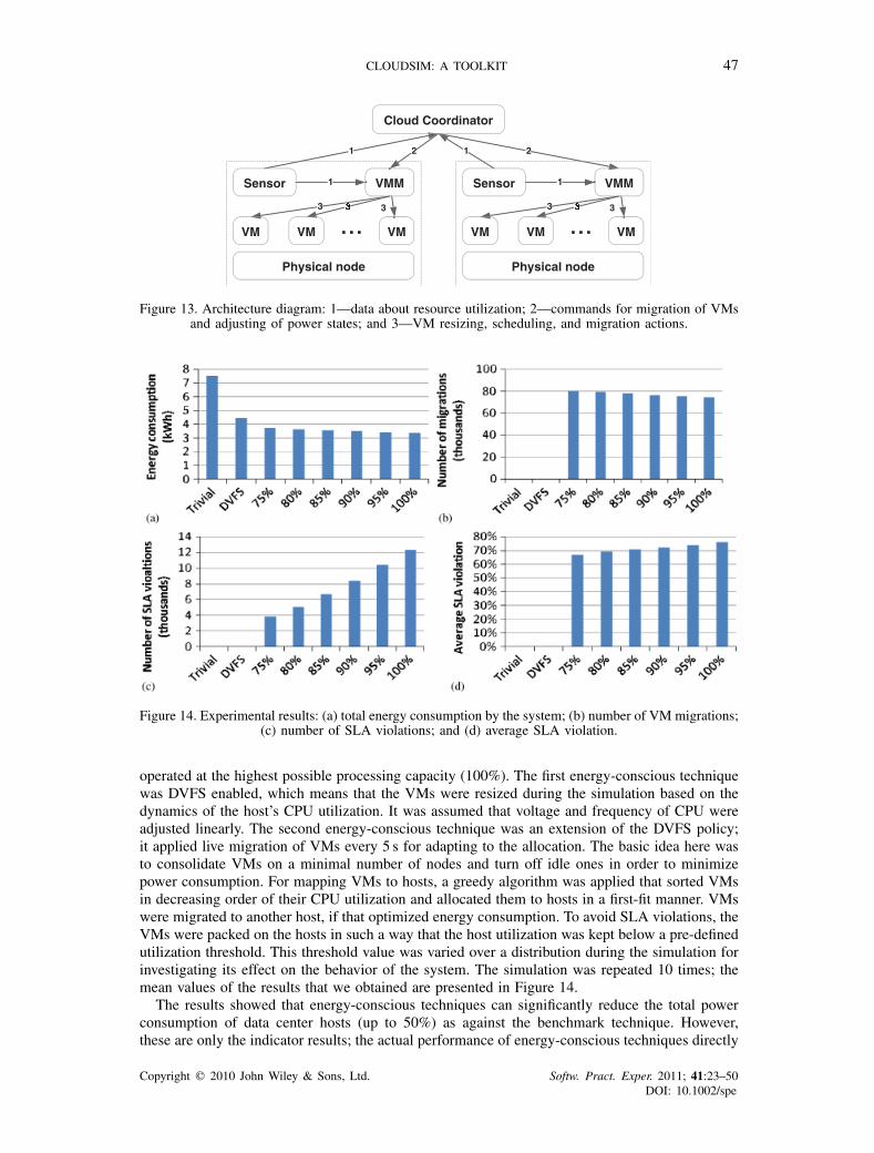
CLOUDSIM: A TOOLKIT 47
Physical node
VM VM VM
Sensor VMM
3333
1
Physical node
VM VM VM
Sensor VMM
3333
1
Cloud Coordinator
1 2 1 2
3 3
Figure 13. Architecture diagram: 1—data about resource utilization; 2—commands for migration of VMsand adjusting of power states; and 3—VM resizing, scheduling, and migration actions.
Figure 14. Experimental results: (a) total energy consumption by the system; (b) number of VM migrations;(c) number of SLA violations; and (d) average SLA violation.
operated at the highest possible processing capacity (100%). The first energy-conscious techniquewas DVFS enabled, which means that the VMs were resized during the simulation based on thedynamics of the host’s CPU utilization. It was assumed that voltage and frequency of CPU wereadjusted linearly. The second energy-conscious technique was an extension of the DVFS policy;it applied live migration of VMs every 5 s for adapting to the allocation. The basic idea here wasto consolidate VMs on a minimal number of nodes and turn off idle ones in order to minimizepower consumption. For mapping VMs to hosts, a greedy algorithm was applied that sorted VMsin decreasing order of their CPU utilization and allocated them to hosts in a first-fit manner. VMswere migrated to another host, if that optimized energy consumption. To avoid SLA violations, theVMs were packed on the hosts in such a way that the host utilization was kept below a pre-definedutilization threshold. This threshold value was varied over a distribution during the simulation forinvestigating its effect on the behavior of the system. The simulation was repeated 10 times; themean values of the results that we obtained are presented in Figure 14.
The results showed that energy-conscious techniques can significantly reduce the total powerconsumption of data center hosts (up to 50%) as against the benchmark technique. However,these are only the indicator results; the actual performance of energy-conscious techniques directly
Copyright q 2010 John Wiley & Sons, Ltd. Softw. Pract. Exper. 2011; 41:23–50DOI: 10.1002/spe
48 R. N. CALHEIROS ET AL.
depends on the type of application service being hosted in the cloud. There is much scope in thisarea for developing application-specific energy optimization techniques. With the growth of theutilization threshold, the energy consumption decreases because VMs can be consolidated moreaggressively. This also leads to a decrease in the number of VM migrations and an increase in thenumber of SLA violations. This simple case study showed how CloudSim can be used to simulatedifferent kinds of energy-conscious resource management techniques/policies.
6. ADDITIONAL CLOUDSIM USE CASES
With the growing popularity and importance of Cloud computing, several external researchersaround the world have started using CloudSim. For instance, HP Labs (Palo Alto) researchers areusing CloudSim for evaluation of resource allocation algorithms for HP’s Cloud data centers; DukeUniversity (U.S.A.) researchers are using it for energy-efficient management of data centers; ChinaEast Jiao Tong University researchers are using CloudSim for evaluating design and applicationscheduling in Clouds; National Research Center for Intelligent Computer Systems (Beijing, China)researchers are using it for SLA-oriented management and optimization of Cloud computingenvironments; and Kookmin University (Seoul, Korea) researchers are using the toolkit for theirinvestigation on workflow scheduling in Clouds.
Cloud analyst [22] is a tool developed at the University of Melbourne whose goal is to supportthe evaluation of social network applications, such as FaceBook, according to the geographicdistribution of users and data centers. In this tool, communities of users and data centers supportingthe social networks are characterized based on their location and other parameters such as userexperience while using the social network application. The load on the data center is continuouslyrecorded in the form of logs. In another use case, CloudSim was successfully deployed to performexperiments related to mapping of VMs on hosts in data centers. CloudSim enabled the evaluationof HMN, a heuristic to achieve reservation of bandwidth between VMs.
These works demonstrate the usefulness of CloudSim in supporting experiments in several areasrelated to Cloud computing and its applications.
7. CONCLUSIONS AND FUTURE WORK
The recent efforts to design and develop Cloud technologies focus on defining novel methods, poli-cies and mechanisms for efficiently managing Cloud infrastructures. To test these newly developedmethods and policies, researchers need tools that allow them to evaluate the hypothesis prior to areal deployment in an environment, where one can reproduce tests. Simulation-based approachesin evaluating Cloud computing systems and application behaviors offer significant benefits, asthey allow Cloud developers: (i) to test the performance of their provisioning and service deliverypolicies in a repeatable and controllable environment free of cost; and (ii) to tune the performancebottlenecks before real-world deployment on commercial Clouds.
To meet these requirements, we have developed the CloudSim toolkit for modeling and simu-lating extensible Clouds. As a completely customizable tool, it allows extension and definition ofpolicies in all the components of the software stack, thereby making it a suitable research toolthat can handle the complexities arising from simulated environments. As future work, we plan toincorporate new pricing and provisioning policies to CloudSim, in order to offer a built-in supportto simulate the currently available Public clouds. Other future directions of this work includeincorporating: (i) workload models; (ii) models for database services such as blob, SQL etc.; (iii)QoS monitoring capability at VM and Cloud level; and (iv) pricing models for public clouds tosupport economy-oriented resource provisioning studies.
Further, the recent studies have revealed that data centers consume unprecedented amountof electrical power; hence, they incur massive capital expenditure for day-to-day operation andmanagement. For example, a Google data center consumes power equivalent to that used by a city
Copyright q 2010 John Wiley & Sons, Ltd. Softw. Pract. Exper. 2011; 41:23–50DOI: 10.1002/spe
CLOUDSIM: A TOOLKIT 49
like San Francisco. The socio-economic factors and environmental conditions of the geograph-ical region where a data center is hosted directly influences the total power bills incurred. Forinstance, a data center hosted in a location where power cost is low and has less hostile weatherconditions would incur comparatively lesser expenditure in power bills. To achieve simulation ofthe aforementioned Cloud computing environments, much of our future work will investigate newmodels and techniques for allocation of services to applications depending on energy efficiencyand expenditure of service providers.
Software availability: The CloudSim software with the source code can be downloaded from:http://www.cloudbus.org/cloudsim/. Various sample programs and tutorials illustrating the use ofCloudSim are also available from the project web site.
ACKNOWLEDGEMENTS
We wish to thank Marcos Dias Assuncao for implementing the simulation core that has been incorporatedinto CloudSim. This work is partially supported by the Australian Department of Innovation, Industry,Science and Research (DIISR) and the Australian Research Council (ARC) through the InternationalScience Linkage and the Discovery Projects programs, respectively, and by CAPES PDEE research grant1185-08-0. This work was primarily carried out at CLOUDS Lab during Rodrigo Calheiros’s visit tothe University of Melbourne and it now continues as a joint effort between Australian and Brazilianresearchers. Dr Rajiv Ranjan thanks CRC Smart Services for funding his position at the University ofNew South Wales. This paper is a substantially extended version of a keynote paper [20], and it focuseson CloudSim.
REFERENCES
1. Armbrust M, Fox A, Griffith R, Joseph A, Katz R, Konwinski A, Lee G, Patterson D, Rabkin A, Stoica I,Zaharia M. A view of cloud computing. Communications of the ACM 2010; 53(4):50–58.
2. Weiss A. Computing in the clouds. NetWorker 2007; 11(4):16–25.3. Buyya R, Yeo CS, Venugopal S, Broberg J, Brandic I. Cloud computing and emerging IT platforms: Vision, hype,
and reality for delivering computing as the 5th utility. Future Generation Computer Systems 2009; 25(6):599–616.4. Amazon Elastic Compute Cloud (EC2). Available at: http://www.amazon.com/ec2/ [18 April 2010].5. Chappell D. Introducing the Azure services platform. White Paper, October 2008.6. Google App Engine. Available at: http://appengine.google.com [18 April 2010].7. Quiroz A, Kim H, Parashar M, Gnanasambandam N, Sharma N. Towards autonomic workload provisioning for
enterprise grids and clouds. Proceedings of the 10th IEEE/ACM International Conference on Grid Computing(Grid 2009), Banf, AB, Canada, 13–15 October 2009. IEEE Computer Society: Silver Spring, MD, 2009; 50–57.
8. Dumitrescu CL, Foster I. GangSim: A simulator for grid scheduling studies. Proceedings of the IEEE InternationalSymposium on Cluster Computing and the Grid, Cardiff, U.K., 2005; 1151–1158.
9. Legrand A, Marchal L, Casanova H. Scheduling distributed applications: The SimGrid simulation framework.Proceedings of the Third IEEE/ACM International Symposium on Cluster Computing and the Grid, Tokyo, Japan,2003; 138–145.
10. Buyya R, Murshed M. GridSim: A toolkit for the modeling and simulation of distributed resource management andscheduling for grid computing. Concurrency and Computation Practice and Experience 2002; 14(13–15):1175–1220.
11. Vecchiola C, Chu X, Buyya R. Aneka: A software platform for .NET-based cloud computing. High Speedand Large Scale Scientific Computing, Gentzsch W, Grandinetti L, Joubert G (eds.). IOS Press: Amsterdam,Netherlands, 2009; 267–295. ISBN: 978-1-60750-073-5.
12. Smith JE, Nair R. Virtual Machines: Versatile Platforms for Systems and Processes. Morgan Kaufmann:Los Altos, CA, 2005.
13. Buyya R, Ranjan R, Calheiros RN. InterCloud: Utility-oriented federation of cloud computing environments forscaling of application services. Proceedings of the 10th International Conference on Algorithms and Architecturesfor Parallel Processing (ICA3PP 2010), Busan, South Korea. Springer: Germany, 21–23 May 2010; 328–336.
14. Foster I, Kesselman C (eds.). The Grid: Blueprint for a New Computing Infrastructure. Morgan Kaufmann:Los Altos, CA, 1999.
15. Bell W, Cameron D, Capozza L, Millar P, Stockinger K, Zini F. Simulation of dynamic Grid replication strategiesin OptorSim. Proceedings of the Third International Workshop on Grid Computing (GRID), Baltimore, U.S.A.IEEE CS Press: Los Alamitos, CA, U.S.A., 18 November 2002; 46–57.
16. Avetisyan AI, Campbel R, Gupta I, Heath MT, Ko SY, Ganger GR, Kozuch MA, O’Hallaron D, Kunze M,Kwan TT, Lai K, Lyons M, Milojicic DS, Lee HY, Soh YC, Ming NK, Luke J-Y, Namgoong H. Open cirrus:A global cloud computing testbed. IEEE Computer 2010; 43(4):35–43.
Copyright q 2010 John Wiley & Sons, Ltd. Softw. Pract. Exper. 2011; 41:23–50DOI: 10.1002/spe
50 R. N. CALHEIROS ET AL.
17. Howell F, Mcnab R. SimJava: A discrete event simulation library for java. Proceedings of the First InternationalConference on Web-based Modeling and Simulation, San Diego, U.S.A., 1998.
18. Medina A, Lakhina A, Matta I, Byer J. BRITE: An approach to universal topology generation. Proceedings ofthe Ninth International Workshop on Modeling, Analysis and Simulation of Computer and TelecommunicationSystems (MASCOTS 2001), Cincinnati, OH, U.S.A., 15–18 August 2001; 346–353.
19. U.S. Environmental Protection Agency. Report to Congress on Server and Data Center Energy Efficiency. U.S.Environmental Protection Agency, 2007; 133 pages.
20. Buyya R, Ranjan R, Calheiros RN. Modeling and simulation of scalable Cloud computing environments and theCloudSim toolkit: Challenges and opportunities. Proceedings of the Conference on High Performance Computingand Simulation (HPCS 2009), Leipzig, Germany. IEEE Press: New York, U.S.A., 21–24 June 2009; 1–11.
21. Raghavendra R, Ranganathan P, Talwar V, Wang Z, Zhu X. No ‘power’ struggles coordinated multi-level powermanagement for the data center. ASPLOS’08, Seattle, Washington, U.S.A., 1–5 March 2008; 48–59.
22. Wickremasinghe B, Calheiros R, Buyya R. CloudAnalyst: A CloudSim-based visual modeller for analysing cloudcomputing environments and applications. Proceedings of the 24th IEEE International Conference on AdvancedInformation Networking and Applications (AINA 2010), Perth, Australia, 20–23 April 2010; 446–452.
Copyright q 2010 John Wiley & Sons, Ltd. Softw. Pract. Exper. 2011; 41:23–50DOI: 10.1002/spe