Embed Size (px)
Citation preview
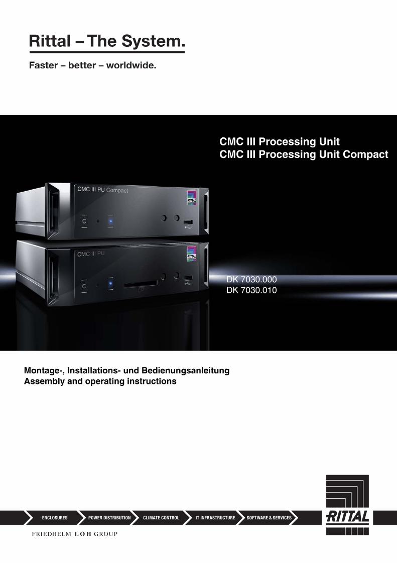
Montage-, Installations- und BedienungsanleitungAssembly and operating instructions
CMC III Processing UnitCMC III Processing Unit Compact
DK 7030.000DK 7030.010
EN
2 Rittal CMC III Processing Unit / CMC III Processing Unit Compact
ForewordForewordDear Customer!
We would like to thank you for choosing our CMC III Processing Unit / CMC III Processing Unit Compact (also referred to hereafter as "CMC III PU")!
We wish you every success!
Your,Rittal GmbH & Co. KG
Rittal GmbH & Co. KGAuf dem Stützelberg
35745 Herborn, GermanyGermany
Tel.: +49 (0) 27 72/50 5-0Fax: +49 (0) 27 72/50 5-23 19
E-mail: [email protected]
We are always happy to answer any technical ques-tions regarding our entire range of products.
EN
Table of contents
Table of contents1 Notes on documentation ................. 51.1 CE labelling .................................................. 51.2 Storing the documents ................................. 51.3 Symbols in these operating instructions ...... 51.4 Associated documents ................................ 51.5 Area of validity ............................................. 5
2 Safety notes .................................... 62.1 General safety notes .................................... 62.2 Service and technical staff .......................... 6
3 Product description ........................ 73.1 Function description and components ........ 73.1.1 Function ............................................................... 73.1.2 Components ........................................................ 73.2 Proper use, anticipated misuse ................... 73.3 Scope of supply ........................................... 7
4 Transportation and handling ........... 84.1 Transportation .............................................. 84.2 Unpacking ................................................... 8
5 Installation ....................................... 95.1 Safety notes ................................................. 95.2 Requirements placed on the installation
location ........................................................ 95.3 Installation procedure .................................. 95.3.1 Installation notes ................................................. 95.3.2 Installation with the mounting clips provided ...... 95.3.3 Installation with the CMC III mounting unit ........ 105.3.4 Top-hat rail mounting ........................................ 115.4 Electrical connection ................................. 115.4.1 Connection using an external power pack ....... 115.4.2 Direct connection .............................................. 115.4.3 Power over Ethernet (PoE) ................................ 125.5 Network connection ................................... 125.6 Connection of sensors ............................... 125.7 Connection of an alarm relay ..................... 125.8 Digital inputs .............................................. 12
6 Commissioning ............................. 136.1 Switching on the CMC III PU ..................... 136.2 Operating and display elements ............... 136.3 Displays of the LEDs .................................. 136.3.1 Multi-LED displays ............................................ 136.3.2 Displays of the LEDs on the CAN bus
connection ......................................................... 136.3.3 Displays of the LEDs on the Ethernet interface . 136.4 Acknowledgement of messages ............... 14
7 Configuration ................................ 157.1 General ...................................................... 157.2 HTTP connection ....................................... 157.2.1 Establishing the connection .............................. 157.2.2 Changing the network settings ......................... 157.2.3 Configuration ..................................................... 16
7.3 Telnet connection ..................................... 167.3.1 Establishing the connection .............................. 167.3.2 Changing the network settings ......................... 177.4 USB/serial connection .............................. 177.4.1 Installing the driver ............................................ 177.4.2 Determining the connection port ....................... 187.4.3 Establishing the connection .............................. 197.4.4 Changing the network settings ......................... 197.5 Basic settings ........................................... 197.5.1 Login to the CMC III PU .................................... 197.5.2 Menu structure .................................................. 207.5.3 Navigating in the menu structure ...................... 207.5.4 Input of values ................................................... 207.5.5 Special settings ................................................. 217.5.6 Logout from the CMC III PU .............................. 21
8 Operation ...................................... 228.1 General ..................................................... 228.2 General operation ..................................... 228.2.1 Structure of the screen pages ........................... 228.2.2 Selection tree in the left-hand area ................... 228.2.3 Tabs in the right-hand area ............................... 228.2.4 Message display ............................................... 238.2.5 Other displays ................................................... 238.2.6 Changing parameter values .............................. 248.2.7 Logout and changing the password ................. 258.2.8 Reorganising the connected components ........ 258.3 "Observation" tab ...................................... 268.3.1 Device ............................................................... 268.3.2 Temperature ...................................................... 268.3.3 Access .............................................................. 268.3.4 Input_1 or Input_2 ............................................. 278.3.5 Output_1 ............................................................ 278.4 "Configuration" tab .................................... 278.5 Network ..................................................... 288.5.1 TCP/IP configuration ......................................... 288.5.2 SNMP configuration .......................................... 288.5.3 HTTP configuration ............................................ 298.5.4 File transfer configuration .................................. 298.5.5 Console ............................................................. 298.5.6 SMTP configuration ........................................... 298.5.7 SMS configuration ............................................. 308.6 System ...................................................... 308.6.1 Syslog ................................................................ 308.6.2 Details ............................................................... 308.6.3 Date/time ........................................................... 318.6.4 General .............................................................. 318.7 Security ..................................................... 318.7.1 Groups .............................................................. 318.7.2 Users ................................................................. 328.8 Access rights ............................................ 328.9 Alarm configuration ................................... 338.9.1 Notifications ....................................................... 338.9.2 Email receivers .................................................. 348.9.3 Trap receivers ................................................... 348.9.4 SMS receivers ................................................... 348.10 Inputs and outputs .................................... 34
Rittal CMC III Processing Unit / CMC III Processing Unit Compact 3
EN
Table of contents
8.11 Logging ..................................................... 358.11.1 Defining a filter ................................................... 358.11.2 Refreshing the view ........................................... 358.11.3 Clearing the display ........................................... 368.11.4 Downloading the log file to a computer ............. 368.12 Tasks ......................................................... 368.12.1 "Tasks" tab ......................................................... 368.12.2 Task configuration ............................................. 368.13 Virtual devices .......................................... 388.13.1 Types of virtual devices ..................................... 388.13.2 Creating a virtual device .................................... 388.13.3 Deleting a virtual device .................................... 389 Updates and data backup ............ 399.1 Establishing an FTP connection ............... 399.2 Perform an update .................................... 399.2.1 Notes for performing an update ........................ 399.2.2 Downloading the software update ..................... 399.2.3 Update via USB ................................................. 399.2.4 Update via FTP or SFTP ..................................... 409.2.5 Perform the update ............................................ 409.3 Performing a data backup ........................ 40
10 Fault and remedial action .............. 4110.1 Configuration change of a switch output .. 4110.2 Opening a comfort handle with the
master key ................................................ 41
11 Storage and disposal .................... 4211.1 Storage ..................................................... 4211.2 Disposal .................................................... 42
12 Technical specifications ................ 43
13 Accessories ................................... 45
14 Glossary ........................................ 46
15 Customer service addresses ........ 47
4 Rittal CMC III Processing Unit / CMC III Processing Unit Compact
Rittal CMC III Processing Unit / CMC III Processing Unit Compact 5
1 Notes on documentation
EN1 Notes on documentation
1.1 CE labellingRittal GmbH & Co. KG confirms the conformance of the CMC III Processing Unit and the CMC III Process-ing Unit Compact to the EU EMC regulation 2004/108/EU. If required, this conformance can be supplied.
1.2 Storing the documentsThe operating, installation and maintenance instruc-tions as well as all applicable documents are an inte-gral part of the product. They must be handed out to those persons who work with the unit and must always be available and on hand for the operating and main-tenance personnel.
1.3 Symbols in these operating instructionsThe following symbols are found in this documenta-tion:
• This symbol indicates an "Action Point" and shows that you should perform an operation/procedure.
1.4 Associated documents– Installation and Short User's Guide
1.5 Area of validityThis guide applies to software version V3.07.03.
Danger! A dangerous situation for which the fail-ure to comply with this note causes death or severe injury.
Warning!A dangerous situation for which the fail-ure to comply with this note can cause death or severe injury.
Caution!A dangerous situation for which the fail-ure to comply with this note can cause (minor) injuries.
Note:Identification of the situations that can lead to material damage.
2 Safety notes
EN
6 Rittal CMC III Processing Unit / CMC III Processing Unit Compact
2 Safety notes
2.1 General safety notesPlease observe the subsequent general safety notes for the installation and operation of the system:– Assembly and installation of the CMC III PU, in par-
ticular the wiring with mains power, may be per-formed only by a trained electrician.
– Please observe the valid regulations for the electri-cal installation for the country in which the CMC III PU is installed and operated, and the na-tional regulations for accident prevention. Please also observe any company-internal regulations, such as work, operating and safety regulations.
– Use only original Rittal products or products recom-mended by Rittal in conjunction with the CMC III PU.
– Please do not make any changes to the CMC III PU that are not described in this manual or in the asso-ciated manuals.
– The operating safety of the CMC III PU is guaran-teed only for the intended use. The technical data and limit values stated in the technical specifications may not be exceeded under any circumstances. In particular, this applies to the specified ambient tem-perature range and IP degree of protection.
– The CMC III PU must not be opened. The unit does not contain any parts that need servicing.
– The operation of the system in direct contact with water, aggressive materials or inflammable gases and vapours is prohibited.
– The CMC III PU must be disconnected from the mains when it is connected with other units.
– Other than these general safety notes, ensure you also observe the specific safety notes when the tasks described in the following chapters are per-formed.
2.2 Service and technical staff– The assembly, commissioning, maintenance and re-
pair of this unit may be performed only by qualified mechanically and electro-technically trained per-sonnel.
– Only properly instructed personnel may perform service on a unit while in operation.
Rittal CMC III Processing Unit / CMC III Processing Unit Compact 7
3 Product description
EN3 Product description
3.1 Function description and components
3.1.1 FunctionThe CMC III PU is the core product of the Rittal enclo-sure monitoring and control system for the electronic monitoring of enclosures and server racks. It provides an Ethernet LAN interface in conjunction with a web site for user communication. In addition to the inte-grated sensors, the CAN bus interface allows a wide range of sensors, actuators and systems for access monitoring to be connected. All sensors initialise themselves automatically after connection to the CAN bus system.Two redundant 24 VDC connections are provided to supply power. The system can also be supplied with Power over Ethernet. In this case, the bus cables then supply power to the connected CAN bus sensors.
3.1.2 ComponentsThe device consists of a compact plastic housing in RAL 7035 with ventilated front in RAL 9005.
3.2 Proper use, anticipated misuseThe device is used only as an enclosure monitoring system and for the administration of the various enclo-sure parameters. Any other use is not permitted.
The unit is state of the art and built according to rec-ognised safety regulations. Nevertheless, improper use can present a hazard to life and limb of the user or third parties, or result in possible impairment of the system and other property.
The unit should thus only be used properly and in technically sound condition. Any malfunctions which impair safety should be rectified immediately! Follow the operating instructions!
The intended use also includes following the accom-panying documentation as well as fulfilling the inspec-tion and maintenance conditions.
Rittal GmbH & Co. KG is not responsible for any dam-age which may result from failure to comply with the accompanying documentation. This also applies to failure to comply with the valid documentation for the used accessories.
Inappropriate use may result in danger. Inappropriate use may include:– Use of impermissible tools.– Improper use.– Improper rectification of malfunctions.– Use of accessories not authorised by Rittal GmbH &
Co. KG.
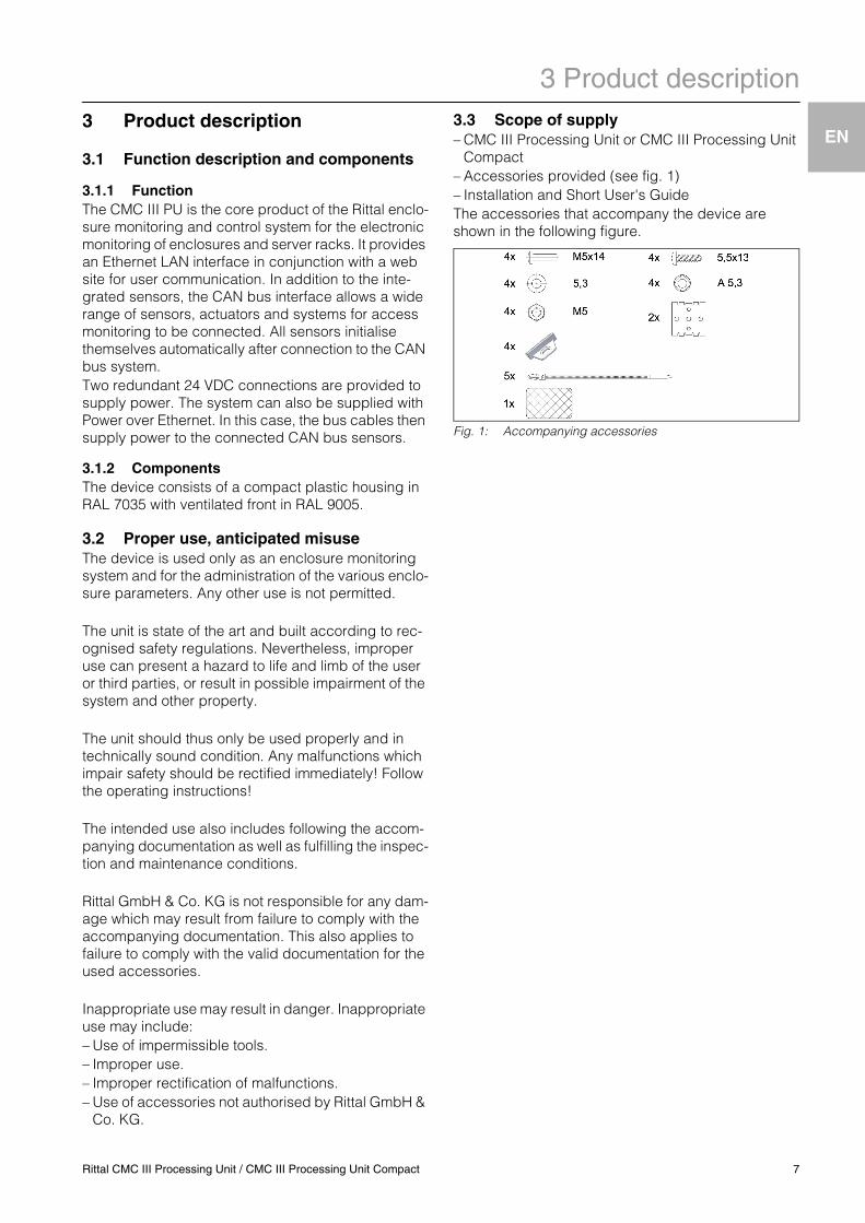
3.3 Scope of supply– CMC III Processing Unit or CMC III Processing Unit
Compact– Accessories provided (see fig. 1)– Installation and Short User's GuideThe accessories that accompany the device are shown in the following figure.
Fig. 1: Accompanying accessories
4 Transportation and handling
EN
8 Rittal CMC III Processing Unit / CMC III Processing Unit Compact
4 Transportation and handling
4.1 TransportationThe device is supplied in a carton.
4.2 Unpacking• Remove the unit's packaging materials.
• Check the unit for any damage that occurred during transport.
• Remove the device from the packaging.• Remove the protective film from the front cover of the
device.
Note:After unpacking, the packaging materials must be disposed of in an environmentally friendly way. It consists of the following ma-terials:Polyethylene film (PE film), cardboard.
Note:Damage and other faults, e.g. incomplete delivery, should immediately be reported to the shipping company and to Rittal GmbH & Co. KG in writing.
5 Installation
EN
5 Installation5.1 Safety notes
• Please observe the valid regulations for the electri-cal installation for the country in which the CMC III PU is installed and operated, and the na-tional regulations for accident prevention. Please also observe any company-internal regulations, such as work, operating and safety regulations.
• The technical data and limit values stated in the technical specifications must not be exceeded un-der any circumstances. In particular, this applies to the specified ambient temperature range and the IP category.
• If a higher IP degree of protection is required for a special application, the CMC III PU must be in-stalled in an appropriate housing or enclosure with the required IP category.
5.2 Requirements placed on the installation location
To ensure the correct operation of the device, the con-ditions for the installation location described in chapter 12 "Technical specifications" must be ob-served.
Electromagnetic interference– Interfering electrical installations (high frequency)
should be avoided.
5.3 Installation procedure
In general, there are several ways of installing the CMC III PU in a server enclosure:1. Installation using the mounting clips provided,
possibly also with spring clips for the top-hat rail installation
2. Installation with the CMC III mounting unit (DK 7030.071)
3. Installation with the CMC III mounting unit, 1 U (DK 7030.070)
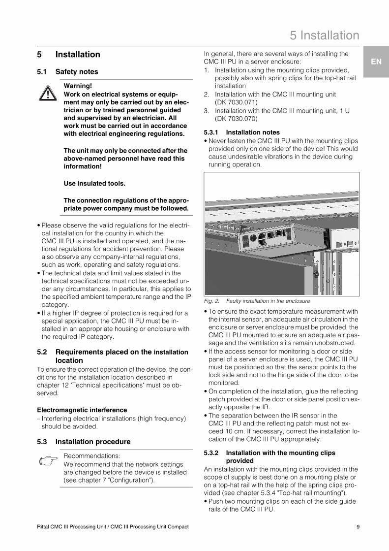
5.3.1 Installation notes• Never fasten the CMC III PU with the mounting clips
provided only on one side of the device! This would cause undesirable vibrations in the device during running operation.
Fig. 2: Faulty installation in the enclosure
• To ensure the exact temperature measurement with the internal sensor, an adequate air circulation in the enclosure or server enclosure must be provided, the CMC III PU mounted to ensure an adequate air pas-sage and the ventilation slits remain unobstructed.
• If the access sensor for monitoring a door or side panel of a server enclosure is used, the CMC III PU must be positioned so that the sensor points to the lock side and not to the hinge side of the door to be monitored.
• On completion of the installation, glue the reflecting patch provided at the door or side panel position ex-actly opposite the IR.
• The separation between the IR sensor in the CMC III PU and the reflecting patch must not ex-ceed 10 cm. If necessary, correct the installation lo-cation of the CMC III PU appropriately.
5.3.2 Installation with the mounting clips provided
An installation with the mounting clips provided in the scope of supply is best done on a mounting plate or on a top-hat rail with the help of the spring clips pro-vided (see chapter 5.3.4 "Top-hat rail mounting").• Push two mounting clips on each of the side guide
rails of the CMC III PU.
Warning! Work on electrical systems or equip-ment may only be carried out by an elec-trician or by trained personnel guided and supervised by an electrician. All work must be carried out in accordance with electrical engineering regulations.
The unit may only be connected after the above-named personnel have read this information!
Use insulated tools.
The connection regulations of the appro-priate power company must be followed.
Recommendations:We recommend that the network settings are changed before the device is installed (see chapter 7 "Configuration").
Rittal CMC III Processing Unit / CMC III Processing Unit Compact 9
5 Installation
EN
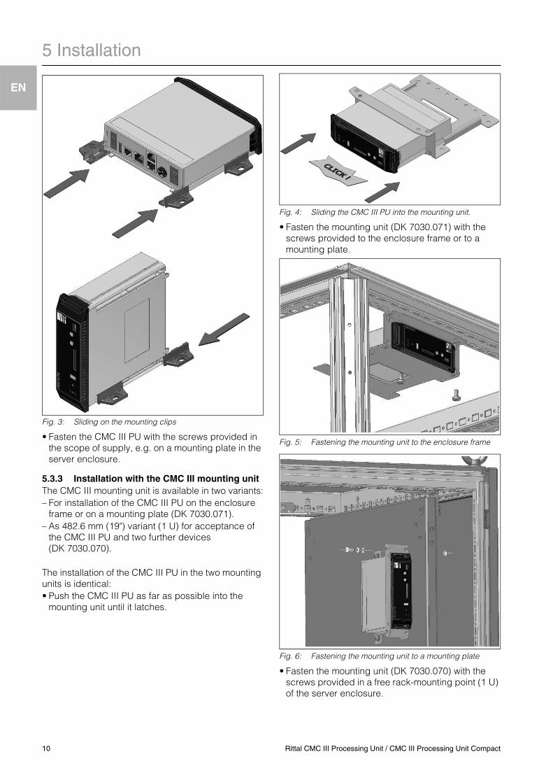
Fig. 3: Sliding on the mounting clips
• Fasten the CMC III PU with the screws provided in the scope of supply, e.g. on a mounting plate in the server enclosure.
5.3.3 Installation with the CMC III mounting unitThe CMC III mounting unit is available in two variants:– For installation of the CMC III PU on the enclosure
frame or on a mounting plate (DK 7030.071).– As 482.6 mm (19") variant (1 U) for acceptance of
the CMC III PU and two further devices (DK 7030.070).
The installation of the CMC III PU in the two mounting units is identical:• Push the CMC III PU as far as possible into the
mounting unit until it latches.
Fig. 4: Sliding the CMC III PU into the mounting unit.
• Fasten the mounting unit (DK 7030.071) with the screws provided to the enclosure frame or to a mounting plate.
Fig. 5: Fastening the mounting unit to the enclosure frame
Fig. 6: Fastening the mounting unit to a mounting plate
• Fasten the mounting unit (DK 7030.070) with the screws provided in a free rack-mounting point (1 U) of the server enclosure.
10 Rittal CMC III Processing Unit / CMC III Processing Unit Compact
5 Installation
EN
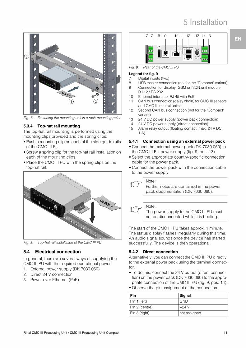
Fig. 7: Fastening the mounting unit in a rack-mounting point
5.3.4 Top-hat rail mountingThe top-hat rail mounting is performed using the mounting clips provided and the spring clips.• Push a mounting clip on each of the side guide rails
of the CMC III PU.• Screw a spring clip for the top-hat rail installation on
each of the mounting clips.• Place the CMC III PU with the spring clips on the
top-hat rail.
Fig. 8: Top-hat rail installation of the CMC III PU
5.4 Electrical connection
In general, there are several ways of supplying the CMC III PU with the required operational power:1. External power supply (DK 7030.060)2. Direct 24 V connection3. Power over Ethernet (PoE)
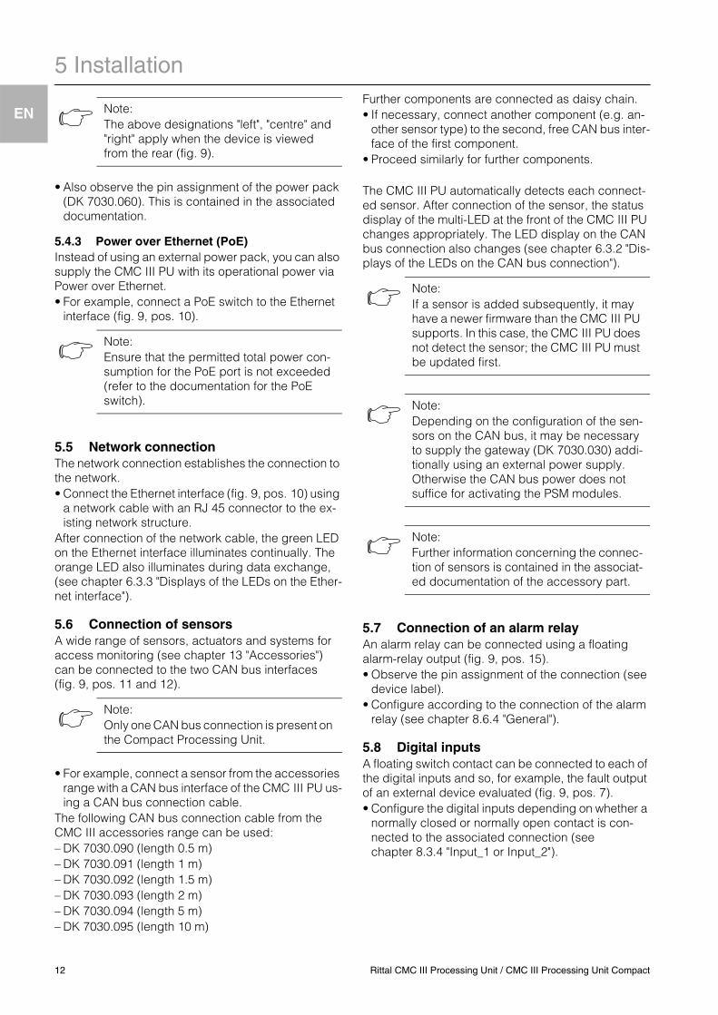
Fig. 9: Rear of the CMC III PU
Legend for fig. 97 Digital inputs (two)8 USB master connection (not for the "Compact" variant)9 Connection for display, GSM or ISDN unit module,
RJ 12 / RS 23210 Ethernet interface, RJ 45 with PoE11 CAN bus connection (daisy chain) for CMC III sensors
and CMC III control units12 Second CAN bus connection (not for the "Compact"
variant)13 24 V DC power supply (power pack connection)14 24 V DC power supply (direct connection)15 Alarm relay output (floating contact, max. 24 V DC,
1 A)
5.4.1 Connection using an external power pack• Connect the external power pack (DK 7030.060) to
the CMC III PU power supply (fig. 9, pos. 13).• Select the appropriate country-specific connection
cable for the power pack.• Connect the power pack with the connection cable
to the power supply.
The start of the CMC III PU takes approx. 1 minute. The status display flashes irregularly during this time. An audio signal sounds once the device has started successfully. The device is then operational.
5.4.2 Direct connectionAlternatively, you can connect the CMC III PU directly to the external power pack using the terminal connec-tor.• To do this, connect the 24 V output (direct connec-
tion) on the power pack (DK 7030.060) to the appro-priate connection of the CMC III PU (fig. 9, pos. 14).
• Observe the pin assignment of the connection.
Note:Further notes are contained in the power pack documentation (DK 7030.060).
Note:The power supply to the CMC III PU must not be disconnected while it is booting.
Pin Signal
Pin 1 (left) GND
Pin 2 (centre) +24 V
Pin 3 (right) not assigned
Rittal CMC III Processing Unit / CMC III Processing Unit Compact 11
5 Installation
EN
• Also observe the pin assignment of the power pack (DK 7030.060). This is contained in the associated documentation.
5.4.3 Power over Ethernet (PoE)Instead of using an external power pack, you can also supply the CMC III PU with its operational power via Power over Ethernet.• For example, connect a PoE switch to the Ethernet
interface (fig. 9, pos. 10).
5.5 Network connectionThe network connection establishes the connection to the network.• Connect the Ethernet interface (fig. 9, pos. 10) using
a network cable with an RJ 45 connector to the ex-isting network structure.
After connection of the network cable, the green LED on the Ethernet interface illuminates continually. The orange LED also illuminates during data exchange, (see chapter 6.3.3 "Displays of the LEDs on the Ether-net interface").
5.6 Connection of sensorsA wide range of sensors, actuators and systems for access monitoring (see chapter 13 "Accessories") can be connected to the two CAN bus interfaces (fig. 9, pos. 11 and 12).
• For example, connect a sensor from the accessories range with a CAN bus interface of the CMC III PU us-ing a CAN bus connection cable.
The following CAN bus connection cable from the CMC III accessories range can be used:– DK 7030.090 (length 0.5 m)– DK 7030.091 (length 1 m)– DK 7030.092 (length 1.5 m)– DK 7030.093 (length 2 m)– DK 7030.094 (length 5 m)– DK 7030.095 (length 10 m)
Further components are connected as daisy chain.• If necessary, connect another component (e.g. an-
other sensor type) to the second, free CAN bus inter-face of the first component.
• Proceed similarly for further components.
The CMC III PU automatically detects each connect-ed sensor. After connection of the sensor, the status display of the multi-LED at the front of the CMC III PU changes appropriately. The LED display on the CAN bus connection also changes (see chapter 6.3.2 "Dis-plays of the LEDs on the CAN bus connection").
5.7 Connection of an alarm relayAn alarm relay can be connected using a floating alarm-relay output (fig. 9, pos. 15).• Observe the pin assignment of the connection (see
device label).• Configure according to the connection of the alarm
relay (see chapter 8.6.4 "General").
5.8 Digital inputsA floating switch contact can be connected to each of the digital inputs and so, for example, the fault output of an external device evaluated (fig. 9, pos. 7).• Configure the digital inputs depending on whether a
normally closed or normally open contact is con-nected to the associated connection (see chapter 8.3.4 "Input_1 or Input_2").
Note:The above designations "left", "centre" and "right" apply when the device is viewed from the rear (fig. 9).
Note:Ensure that the permitted total power con-sumption for the PoE port is not exceeded (refer to the documentation for the PoE switch).
Note:Only one CAN bus connection is present on the Compact Processing Unit.
Note:If a sensor is added subsequently, it may have a newer firmware than the CMC III PU supports. In this case, the CMC III PU does not detect the sensor; the CMC III PU must be updated first.
Note:Depending on the configuration of the sen-sors on the CAN bus, it may be necessary to supply the gateway (DK 7030.030) addi-tionally using an external power supply. Otherwise the CAN bus power does not suffice for activating the PSM modules.
Note:Further information concerning the connec-tion of sensors is contained in the associat-ed documentation of the accessory part.
12 Rittal CMC III Processing Unit / CMC III Processing Unit Compact
6 Commissioning
EN
6 Commissioning6.1 Switching on the CMC III PU Once the electrical connection has been established, the CMC III PU starts automatically (see chapter 5.4 "Electrical connection"). A separate switch-on is not required.
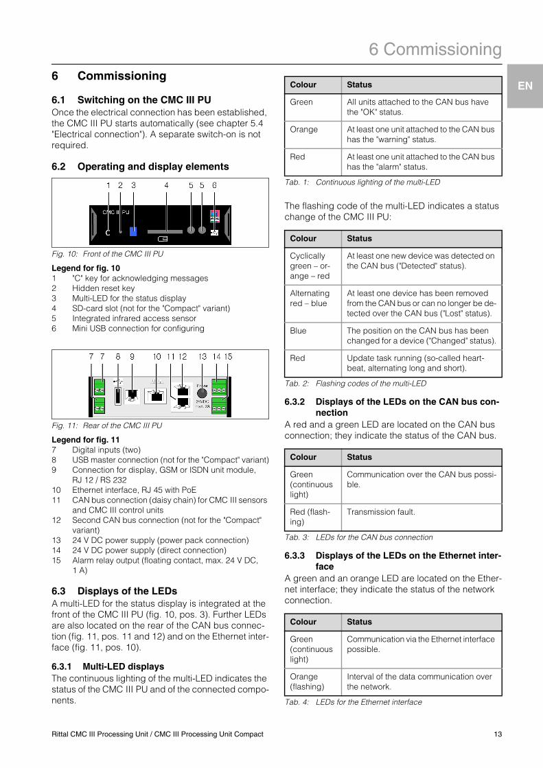
6.2 Operating and display elements
Fig. 10: Front of the CMC III PU
Legend for fig. 101 "C" key for acknowledging messages2 Hidden reset key3 Multi-LED for the status display4 SD-card slot (not for the "Compact" variant)5 Integrated infrared access sensor6 Mini USB connection for configuring
Fig. 11: Rear of the CMC III PU
Legend for fig. 117 Digital inputs (two)8 USB master connection (not for the "Compact" variant)9 Connection for display, GSM or ISDN unit module,
RJ 12 / RS 23210 Ethernet interface, RJ 45 with PoE11 CAN bus connection (daisy chain) for CMC III sensors
and CMC III control units12 Second CAN bus connection (not for the "Compact"
variant)13 24 V DC power supply (power pack connection)14 24 V DC power supply (direct connection)15 Alarm relay output (floating contact, max. 24 V DC,
1 A)
6.3 Displays of the LEDsA multi-LED for the status display is integrated at the front of the CMC III PU (fig. 10, pos. 3). Further LEDs are also located on the rear of the CAN bus connec-tion (fig. 11, pos. 11 and 12) and on the Ethernet inter-face (fig. 11, pos. 10).
6.3.1 Multi-LED displaysThe continuous lighting of the multi-LED indicates the status of the CMC III PU and of the connected compo-nents.
Tab. 1: Continuous lighting of the multi-LED
The flashing code of the multi-LED indicates a status change of the CMC III PU:
Tab. 2: Flashing codes of the multi-LED
6.3.2 Displays of the LEDs on the CAN bus con-nection
A red and a green LED are located on the CAN bus connection; they indicate the status of the CAN bus.
Tab. 3: LEDs for the CAN bus connection
6.3.3 Displays of the LEDs on the Ethernet inter-face
A green and an orange LED are located on the Ether-net interface; they indicate the status of the network connection.
Tab. 4: LEDs for the Ethernet interface
Colour Status
Green All units attached to the CAN bus have the "OK" status.
Orange At least one unit attached to the CAN bus has the "warning" status.
Red At least one unit attached to the CAN bus has the "alarm" status.
Colour Status
Cyclically green – or-ange – red
At least one new device was detected on the CAN bus ("Detected" status).
Alternating red – blue
At least one device has been removed from the CAN bus or can no longer be de-tected over the CAN bus ("Lost" status).
Blue The position on the CAN bus has been changed for a device ("Changed" status).
Red Update task running (so-called heart-beat, alternating long and short).
Colour Status
Green (continuous light)
Communication over the CAN bus possi-ble.
Red (flash-ing)
Transmission fault.
Colour Status
Green (continuous light)
Communication via the Ethernet interface possible.
Orange (flashing)
Interval of the data communication over the network.
Rittal CMC III Processing Unit / CMC III Processing Unit Compact 13
6 Commissioning
EN
6.4 Acknowledgement of messagesThere are generally three ways of acknowledging messages:1. A short press of the "C" key on the CMC III PU.This confirms all alarm messages concurrently.2. A right-click on a message in the message display
and a left-click on the "Acknowledge" entry in the context menu. If an alarm message is selected, only the currently selected message will be confirmed. If a message concerning a configuration change is selected, all associated messages will be con-firmed together.
3. A right-click on the entry for a component in the selection tree and a left-click on the "Acknowl-edge" entry in the context menu.This confirms pending alarm messages for this component.A configuration change cannot be confirmed in the selection tree.
14 Rittal CMC III Processing Unit / CMC III Processing Unit Compact
7 Configuration
EN
7 Configuration7.1 GeneralThe base configuration of the CMC III PU, in particular the (one-off) customisation of the network settings, can be performed in several ways:1. HTTP connection via the Ethernet interface2. Telnet connection via the Ethernet interface3. Serial connection via a USB cable
An HTTP connection is normally used to make the set-tings. If this is not possible, e.g. because access via HTTP or HTTPS has been deactivated, access via a Telnet connection is recommended. To do this, as for access using an HTTP connection, the IP address of the CMC III PU must be known. If this address is not known, a direct access to the device can be made us-ing the USB/serial interface at the front of the device.The following descriptions assume that the CMC III PU is in its delivered state, i.e. no changes have been made to the base configuration. In particu-lar, the "HTTP" and "Telnet" connection types must not be blocked.
7.2 HTTP connection
7.2.1 Establishing the connection• Connect the device with a network cable using the
Ethernet interface to your computer (fig. 11, pos. 10).
• Change the IP address of your computer to any ad-dress in the range 192.168.0.xxx, e.g. 192.168.0.191. The default address 192.168.0.190 of the device must not be used.
• Set the subnet mask to the value 255.255.255.0.• If necessary, switch off the proxy server in the
browser in order to permit a direct connection to the device.
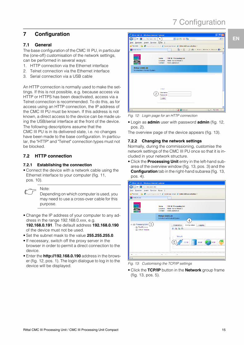
• Enter the http://192.168.0.190 address in the brows-er (fig. 12, pos. 1). The login dialogue to log in to the device will be displayed.
Fig. 12: Login page for an HTTP connection
• Login as admin user with password admin (fig. 12, pos. 2).
The overview page of the device appears (fig. 13).
7.2.2 Changing the network settingsNormally, during the commissioning, customise the network settings of the CMC III PU once so that it is in-cluded in your network structure.• Click the Processing Unit entry in the left-hand sub-
area of the overview window (fig. 13, pos. 3) and the Configuration tab in the right-hand subarea (fig. 13, pos. 4).
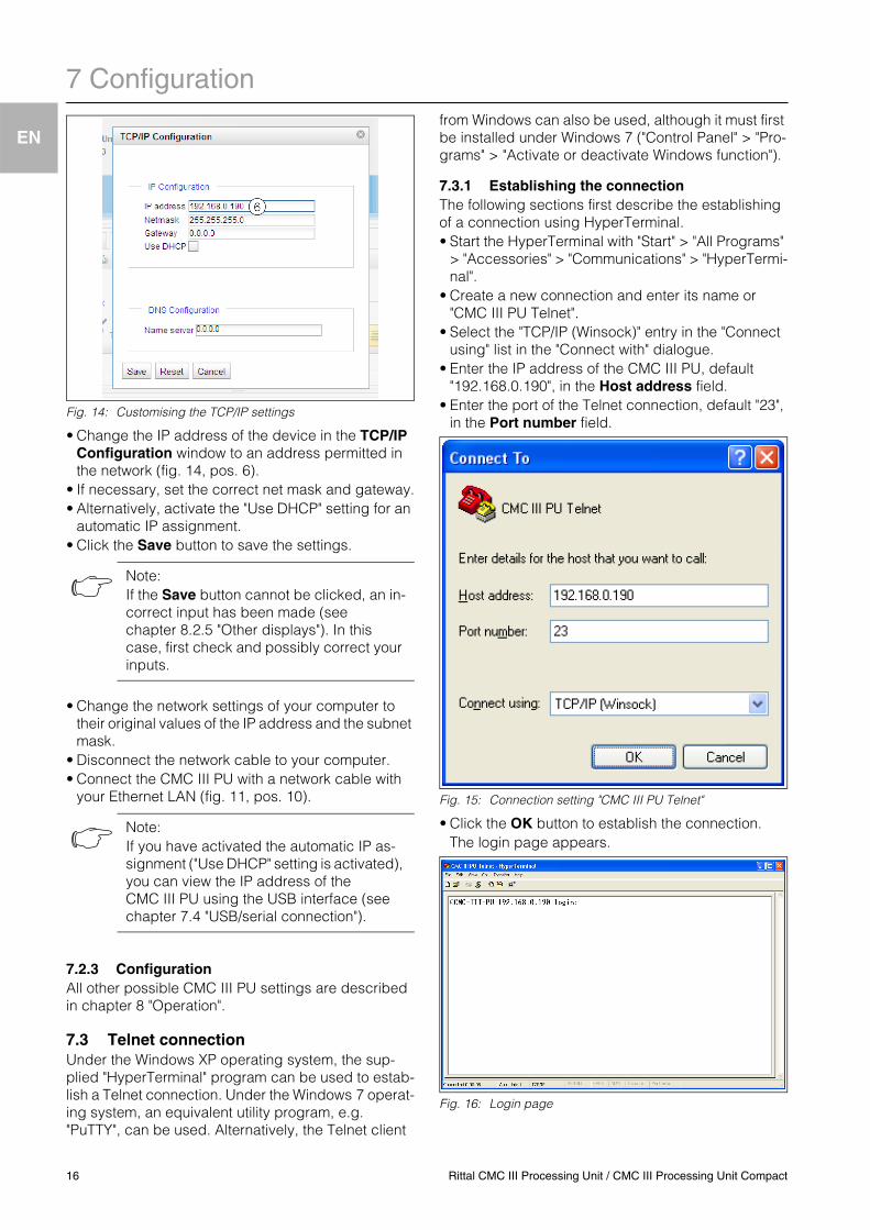
Fig. 13: Customising the TCP/IP settings
• Click the TCP/IP button in the Network group frame (fig. 13, pos. 5).
Note:Depending on which computer is used, you may need to use a cross-over cable for this purpose.
Rittal CMC III Processing Unit / CMC III Processing Unit Compact 15
7 Configuration
EN
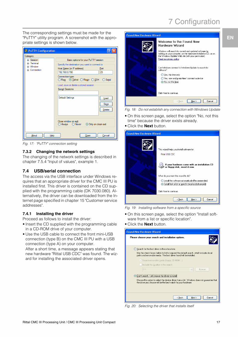
Fig. 14: Customising the TCP/IP settings
• Change the IP address of the device in the TCP/IP Configuration window to an address permitted in the network (fig. 14, pos. 6).
• If necessary, set the correct net mask and gateway.• Alternatively, activate the "Use DHCP" setting for an
automatic IP assignment.• Click the Save button to save the settings.
• Change the network settings of your computer to their original values of the IP address and the subnet mask.
• Disconnect the network cable to your computer.• Connect the CMC III PU with a network cable with
your Ethernet LAN (fig. 11, pos. 10).
7.2.3 ConfigurationAll other possible CMC III PU settings are described in chapter 8 "Operation".
7.3 Telnet connectionUnder the Windows XP operating system, the sup-plied "HyperTerminal" program can be used to estab-lish a Telnet connection. Under the Windows 7 operat-ing system, an equivalent utility program, e.g. "PuTTY", can be used. Alternatively, the Telnet client
from Windows can also be used, although it must first be installed under Windows 7 ("Control Panel" > "Pro-grams" > "Activate or deactivate Windows function").
7.3.1 Establishing the connectionThe following sections first describe the establishing of a connection using HyperTerminal. • Start the HyperTerminal with "Start" > "All Programs"
> "Accessories" > "Communications" > "HyperTermi-nal".
• Create a new connection and enter its name or "CMC III PU Telnet".
• Select the "TCP/IP (Winsock)" entry in the "Connect using" list in the "Connect with" dialogue.
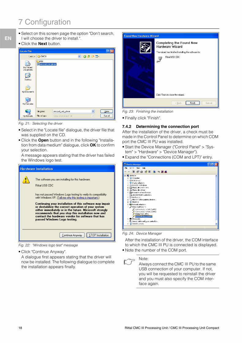
• Enter the IP address of the CMC III PU, default "192.168.0.190", in the Host address field.
• Enter the port of the Telnet connection, default "23", in the Port number field.
Fig. 15: Connection setting "CMC III PU Telnet"
• Click the OK button to establish the connection.The login page appears.
Fig. 16: Login page
Note:If the Save button cannot be clicked, an in-correct input has been made (see chapter 8.2.5 "Other displays"). In this case, first check and possibly correct your inputs.
Note:If you have activated the automatic IP as-signment ("Use DHCP" setting is activated), you can view the IP address of the CMC III PU using the USB interface (see chapter 7.4 "USB/serial connection").
16 Rittal CMC III Processing Unit / CMC III Processing Unit Compact
7 Configuration
EN
The corresponding settings must be made for the "PuTTY" utility program. A screenshot with the appro-priate settings is shown below.Fig. 17: "PuTTY" connection setting
7.3.2 Changing the network settingsThe changing of the network settings is described in chapter 7.5.4 "Input of values", example 1.
7.4 USB/serial connectionThe access via the USB interface under Windows re-quires that an appropriate driver for the CMC III PU is installed first. This driver is contained on the CD sup-plied with the programming cable (DK 7030.080). Al-ternatively, the driver can be downloaded from the In-ternet page specified in chapter 15 "Customer service addresses".
7.4.1 Installing the driverProceed as follows to install the driver:• Insert the CD supplied with the programming cable
in a CD-ROM drive of your computer.• Use the USB cable to connect the front mini-USB
connection (type B) on the CMC III PU with a USB connection (type A) on your computer.After a short time, a message appears stating that new hardware "Rittal USB CDC" was found. The wiz-ard for installing the associated driver opens.
Fig. 18: Do not establish any connection with Windows Update
• On this screen page, select the option "No, not this time" because the driver exists already.
• Click the Next button.
Fig. 19: Installing software from a specific source
• On this screen page, select the option "Install soft-ware from a list or specific location".
• Click the Next button.
Fig. 20: Selecting the driver that installs itself
Rittal CMC III Processing Unit / CMC III Processing Unit Compact 17
7 Configuration
EN
• Select on this screen page the option "Don’t search,I will choose the driver to install.".• Click the Next button.
Fig. 21: Selecting the driver
• Select in the "Locate file" dialogue, the driver file that was supplied on the CD.
• Click the Open button and in the following "Installa-tion from data medium" dialogue, click OK to confirm your selection.A message appears stating that the driver has failed the Windows logo test.
Fig. 22: "Windows logo test" message
• Click "Continue Anyway".A dialogue first appears stating that the driver will now be installed. The following dialogue to complete the installation appears finally.
Fig. 23: Finishing the installation
• Finally click "Finish".
7.4.2 Determining the connection portAfter the installation of the driver, a check must be made in the Control Panel to determine on which COM port the CMC III PU was installed.• Start the Device Manager ("Control Panel" > "Sys-
tem" > "Hardware" > "Device Manager").• Expand the "Connections (COM and LPT)" entry.
Fig. 24: Device Manager
After the installation of the driver, the COM interface to which the CMC III PU is connected is displayed.
• Note the number of the COM port.
Note:Always connect the CMC III PU to the same USB connection of your computer. If not, you will be requested to reinstall the driver and you must also specify the COM inter-face again.
18 Rittal CMC III Processing Unit / CMC III Processing Unit Compact
7 Configuration
EN
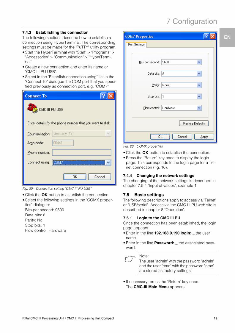
7.4.3 Establishing the connectionThe following sections describe how to establish a connection using HyperTerminal. The corresponding settings must be made for the "PuTTY" utility program.• Start the HyperTerminal with "Start" > "Programs" >"Accessories" > "Communication" > "HyperTermi-nal".
• Create a new connection and enter its name or "CMC III PU USB".
• Select in the "Establish connection using" list in the "Connect To" dialogue the COM port that you speci-fied previously as connection port, e.g. "COM7".
Fig. 25: Connection setting "CMC III PU USB"
• Click the OK button to establish the connection.• Select the following settings in the "COMX proper-
ties" dialogue:Bits per second: 9600Data bits: 8Parity: NoStop bits: 1Flow control: Hardware
Fig. 26: COMX properties
• Click the OK button to establish the connection.• Press the "Return" key once to display the login
page. This corresponds to the login page for a Tel-net connection (fig. 16).
7.4.4 Changing the network settingsThe changing of the network settings is described in chapter 7.5.4 "Input of values", example 1.
7.5 Basic settingsThe following descriptions apply to access via "Telnet" or "USB/serial". Access via the CMC III PU web site is described in chapter 8 "Operation".
7.5.1 Login to the CMC III PUOnce the connection has been established, the login page appears.• Enter in the line 192.168.0.190 login: _ the user
name.• Enter in the line Password: _ the associated pass-
word.
• If necessary, press the "Return" key once.The CMC-III Main Menu appears.
Note:The user "admin" with the password "admin" and the user "cmc" with the password "cmc" are stored as factory settings.
Rittal CMC III Processing Unit / CMC III Processing Unit Compact 19
7 Configuration
EN
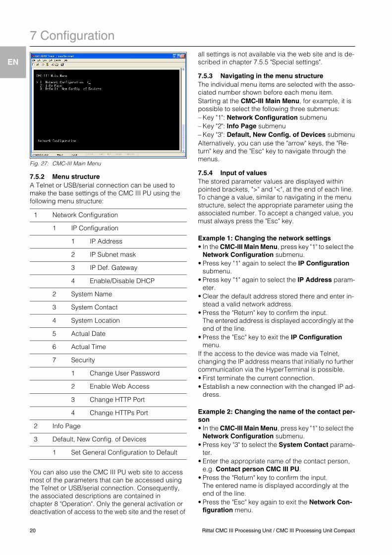
Fig. 27: CMC-III Main Menu
7.5.2 Menu structureA Telnet or USB/serial connection can be used to make the base settings of the CMC III PU using the following menu structure:
You can also use the CMC III PU web site to access most of the parameters that can be accessed using the Telnet or USB/serial connection. Consequently, the associated descriptions are contained in chapter 8 "Operation". Only the general activation or deactivation of access to the web site and the reset of
all settings is not available via the web site and is de-scribed in chapter 7.5.5 "Special settings".
7.5.3 Navigating in the menu structureThe individual menu items are selected with the asso-ciated number shown before each menu item.Starting at the CMC-III Main Menu, for example, it is possible to select the following three submenus:– Key "1": Network Configuration submenu– Key "2": Info Page submenu– Key "3": Default, New Config. of Devices submenuAlternatively, you can use the "arrow" keys, the "Re-turn" key and the "Esc" key to navigate through the menus.
7.5.4 Input of valuesThe stored parameter values are displayed within pointed brackets, ">" and "<", at the end of each line. To change a value, similar to navigating in the menu structure, select the appropriate parameter using the associated number. To accept a changed value, you must always press the "Esc" key.
Example 1: Changing the network settings• In the CMC-III Main Menu, press key "1" to select the
Network Configuration submenu.• Press key "1" again to select the IP Configuration
submenu.• Press key "1" again to select the IP Address param-
eter.• Clear the default address stored there and enter in-
stead a valid network address.• Press the "Return" key to confirm the input.
The entered address is displayed accordingly at the end of the line.
• Press the "Esc" key to exit the IP Configuration menu.
If the access to the device was made via Telnet, changing the IP address means that initially no further communication via the HyperTerminal is possible.• First terminate the current connection.• Establish a new connection with the changed IP ad-
dress.
Example 2: Changing the name of the contact per-son• In the CMC-III Main Menu, press key "1" to select the
Network Configuration submenu.• Press key "3" to select the System Contact parame-
ter.• Enter the appropriate name of the contact person,
e.g. Contact person CMC III PU.• Press the "Return" key to confirm the input.
The entered name is displayed accordingly at the end of the line.
• Press the "Esc" key again to exit the Network Con-figuration menu.
1 Network Configuration
1 IP Configuration
1 IP Address
2 IP Subnet mask
3 IP Def. Gateway
4 Enable/Disable DHCP
2 System Name
3 System Contact
4 System Location
5 Actual Date
6 Actual Time
7 Security
1 Change User Password
2 Enable Web Access
3 Change HTTP Port
4 Change HTTPs Port
2 Info Page
3 Default, New Config. of Devices
1 Set General Configuration to Default
20 Rittal CMC III Processing Unit / CMC III Processing Unit Compact
7 Configuration
EN
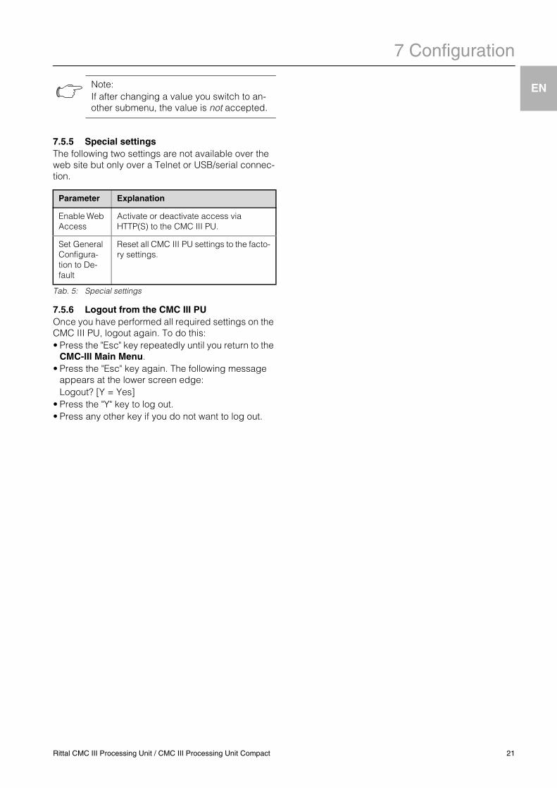
7.5.5 Special settingsThe following two settings are not available over the web site but only over a Telnet or USB/serial connec-tion.
Tab. 5: Special settings
7.5.6 Logout from the CMC III PUOnce you have performed all required settings on the CMC III PU, logout again. To do this:• Press the "Esc" key repeatedly until you return to the
CMC-III Main Menu.• Press the "Esc" key again. The following message
appears at the lower screen edge:Logout? [Y = Yes]
• Press the "Y" key to log out.• Press any other key if you do not want to log out.
Note:If after changing a value you switch to an-other submenu, the value is not accepted.
Parameter Explanation
Enable Web Access
Activate or deactivate access via HTTP(S) to the CMC III PU.
Set General Configura-tion to De-fault
Reset all CMC III PU settings to the facto-ry settings.
Rittal CMC III Processing Unit / CMC III Processing Unit Compact 21
8 Operation
EN
8 Operation8.1 GeneralThis chapter describes all settings available for an HTTP access.
8.2 General operation
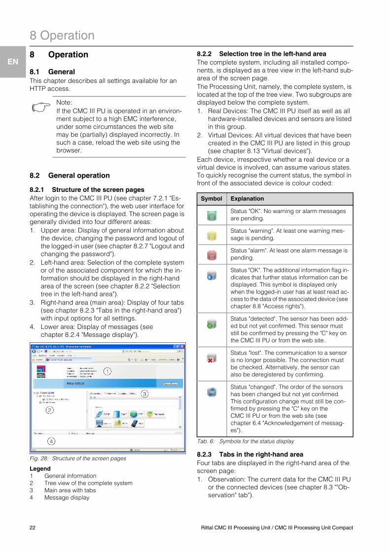
8.2.1 Structure of the screen pagesAfter login to the CMC III PU (see chapter 7.2.1 "Es-tablishing the connection"), the web user interface for operating the device is displayed. The screen page is generally divided into four different areas:1. Upper area: Display of general information about
the device, changing the password and logout of the logged-in user (see chapter 8.2.7 "Logout and changing the password").
2. Left-hand area: Selection of the complete system or of the associated component for which the in-formation should be displayed in the right-hand area of the screen (see chapter 8.2.2 "Selection tree in the left-hand area").
3. Right-hand area (main area): Display of four tabs (see chapter 8.2.3 "Tabs in the right-hand area") with input options for all settings.
4. Lower area: Display of messages (see chapter 8.2.4 "Message display").
Fig. 28: Structure of the screen pages
Legend1 General information2 Tree view of the complete system3 Main area with tabs4 Message display
8.2.2 Selection tree in the left-hand areaThe complete system, including all installed compo-nents, is displayed as a tree view in the left-hand sub-area of the screen page.The Processing Unit, namely, the complete system, is located at the top of the tree view. Two subgroups are displayed below the complete system. 1. Real Devices: The CMC III PU itself as well as all
hardware-installed devices and sensors are listed in this group.
2. Virtual Devices: All virtual devices that have been created in the CMC III PU are listed in this group (see chapter 8.13 "Virtual devices").
Each device, irrespective whether a real device or a virtual device is involved, can assume various states. To quickly recognise the current status, the symbol in front of the associated device is colour coded:
Tab. 6: Symbols for the status display
8.2.3 Tabs in the right-hand areaFour tabs are displayed in the right-hand area of the screen page:1. Observation: The current data for the CMC III PU
or the connected devices (see chapter 8.3 ""Ob-servation" tab").
Note:If the CMC III PU is operated in an environ-ment subject to a high EMC interference, under some circumstances the web site may be (partially) displayed incorrectly. In such a case, reload the web site using the browser.
Symbol Explanation
Status "OK". No warning or alarm messages are pending.
Status "warning". At least one warning mes-sage is pending.
Status "alarm". At least one alarm message is pending.
Status "OK". The additional information flag in-dicates that further status information can be displayed. This symbol is displayed only when the logged-in user has at least read ac-cess to the data of the associated device (see chapter 8.8 "Access rights").
Status "detected". The sensor has been add-ed but not yet confirmed. This sensor must still be confirmed by pressing the "C" key on the CMC III PU or from the web site.
Status "lost". The communication to a sensor is no longer possible. The connection must be checked. Alternatively, the sensor can also be deregistered by confirming.
Status "changed". The order of the sensors has been changed but not yet confirmed. This configuration change must still be con-firmed by pressing the "C" key on the CMC III PU or from the web site (see chapter 6.4 "Acknowledgement of messag-es").
22 Rittal CMC III Processing Unit / CMC III Processing Unit Compact
8 Operation
EN
2. Configuration: The configuration for the basic set-tings (see chapter 8.4 ""Configuration" tab").3. Logging: The message archive for the CMC III PU
or the connected devices (see chapter 8.11 "Log-ging").
4. Tasks: The creation of links for various values and associated actions (see chapter 8.12 "Tasks")
The content of the Observation and Configuration tabs depends on whether the complete system ("Processing Unit" entry) or an individual component, e.g. "CMCIII-PU" entry, has been selected in the left-hand area of the screen page.
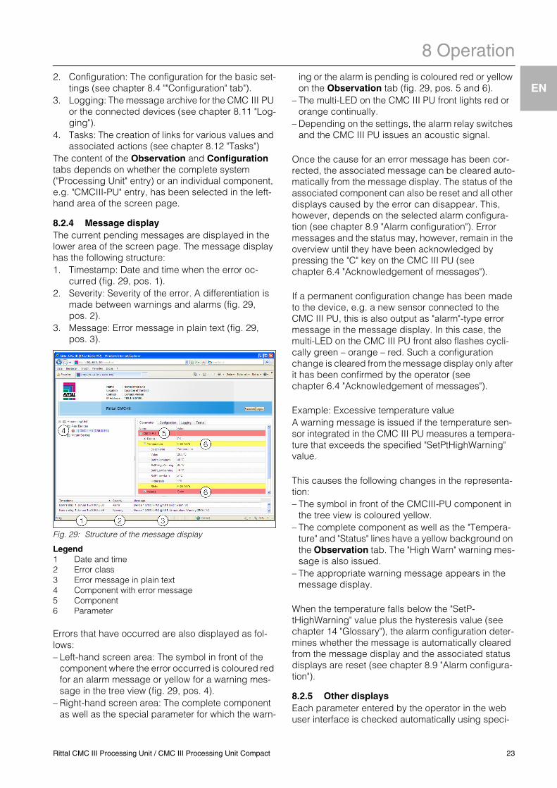
8.2.4 Message displayThe current pending messages are displayed in the lower area of the screen page. The message display has the following structure:1. Timestamp: Date and time when the error oc-
curred (fig. 29, pos. 1).2. Severity: Severity of the error. A differentiation is
made between warnings and alarms (fig. 29, pos. 2).
3. Message: Error message in plain text (fig. 29, pos. 3).
Fig. 29: Structure of the message display
Legend1 Date and time2 Error class3 Error message in plain text4 Component with error message5 Component6 Parameter
Errors that have occurred are also displayed as fol-lows:– Left-hand screen area: The symbol in front of the
component where the error occurred is coloured red for an alarm message or yellow for a warning mes-sage in the tree view (fig. 29, pos. 4).
– Right-hand screen area: The complete component as well as the special parameter for which the warn-
ing or the alarm is pending is coloured red or yellow on the Observation tab (fig. 29, pos. 5 and 6).
– The multi-LED on the CMC III PU front lights red or orange continually.
– Depending on the settings, the alarm relay switches and the CMC III PU issues an acoustic signal.
Once the cause for an error message has been cor-rected, the associated message can be cleared auto-matically from the message display. The status of the associated component can also be reset and all other displays caused by the error can disappear. This, however, depends on the selected alarm configura-tion (see chapter 8.9 "Alarm configuration"). Error messages and the status may, however, remain in the overview until they have been acknowledged by pressing the "C" key on the CMC III PU (see chapter 6.4 "Acknowledgement of messages").
If a permanent configuration change has been made to the device, e.g. a new sensor connected to the CMC III PU, this is also output as "alarm"-type error message in the message display. In this case, the multi-LED on the CMC III PU front also flashes cycli-cally green – orange – red. Such a configuration change is cleared from the message display only after it has been confirmed by the operator (see chapter 6.4 "Acknowledgement of messages").
Example: Excessive temperature valueA warning message is issued if the temperature sen-sor integrated in the CMC III PU measures a tempera-ture that exceeds the specified "SetPtHighWarning" value.
This causes the following changes in the representa-tion:– The symbol in front of the CMCIII-PU component in
the tree view is coloured yellow.– The complete component as well as the "Tempera-
ture" and "Status" lines have a yellow background on the Observation tab. The "High Warn" warning mes-sage is also issued.
– The appropriate warning message appears in the message display.
When the temperature falls below the "SetP-tHighWarning" value plus the hysteresis value (see chapter 14 "Glossary"), the alarm configuration deter-mines whether the message is automatically cleared from the message display and the associated status displays are reset (see chapter 8.9 "Alarm configura-tion").
8.2.5 Other displaysEach parameter entered by the operator in the web user interface is checked automatically using speci-
Rittal CMC III Processing Unit / CMC III Processing Unit Compact 23
8 Operation
EN
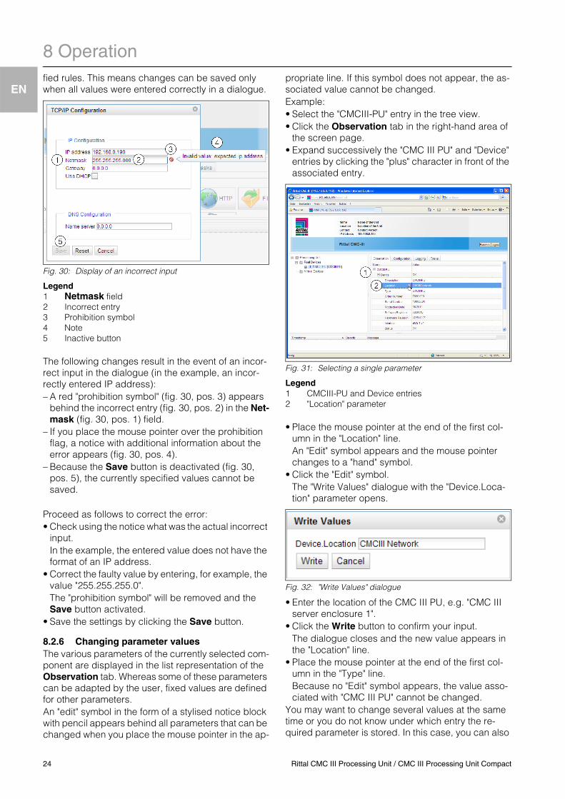
fied rules. This means changes can be saved only when all values were entered correctly in a dialogue.Fig. 30: Display of an incorrect input
Legend1 Netmask field2 Incorrect entry3 Prohibition symbol4 Note5 Inactive button
The following changes result in the event of an incor-rect input in the dialogue (in the example, an incor-rectly entered IP address):– A red "prohibition symbol" (fig. 30, pos. 3) appears
behind the incorrect entry (fig. 30, pos. 2) in the Net-mask (fig. 30, pos. 1) field.
– If you place the mouse pointer over the prohibition flag, a notice with additional information about the error appears (fig. 30, pos. 4).
– Because the Save button is deactivated (fig. 30, pos. 5), the currently specified values cannot be saved.
Proceed as follows to correct the error:• Check using the notice what was the actual incorrect
input.In the example, the entered value does not have the format of an IP address.
• Correct the faulty value by entering, for example, the value "255.255.255.0".The "prohibition symbol" will be removed and the Save button activated.
• Save the settings by clicking the Save button.
8.2.6 Changing parameter valuesThe various parameters of the currently selected com-ponent are displayed in the list representation of the Observation tab. Whereas some of these parameters can be adapted by the user, fixed values are defined for other parameters.An "edit" symbol in the form of a stylised notice block with pencil appears behind all parameters that can be changed when you place the mouse pointer in the ap-
propriate line. If this symbol does not appear, the as-sociated value cannot be changed.Example:• Select the "CMCIII-PU" entry in the tree view.• Click the Observation tab in the right-hand area of
the screen page.• Expand successively the "CMC III PU" and "Device"
entries by clicking the "plus" character in front of the associated entry.
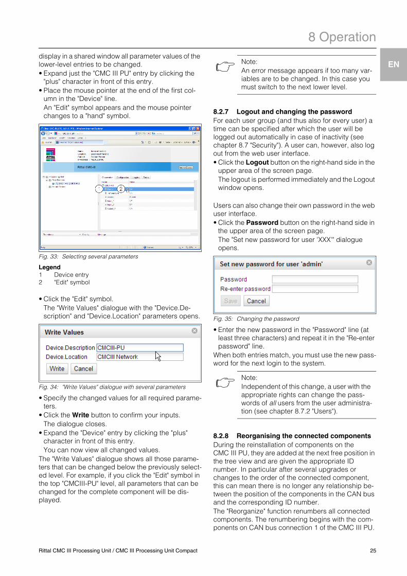
Fig. 31: Selecting a single parameter
Legend1 CMCIII-PU and Device entries2 "Location" parameter
• Place the mouse pointer at the end of the first col-umn in the "Location" line.An "Edit" symbol appears and the mouse pointer changes to a "hand" symbol.
• Click the "Edit" symbol.The "Write Values" dialogue with the "Device.Loca-tion" parameter opens.
Fig. 32: "Write Values" dialogue
• Enter the location of the CMC III PU, e.g. "CMC III server enclosure 1".
• Click the Write button to confirm your input.The dialogue closes and the new value appears in the "Location" line.
• Place the mouse pointer at the end of the first col-umn in the "Type" line.Because no "Edit" symbol appears, the value asso-ciated with "CMC III PU" cannot be changed.
You may want to change several values at the same time or you do not know under which entry the re-quired parameter is stored. In this case, you can also
24 Rittal CMC III Processing Unit / CMC III Processing Unit Compact
8 Operation
EN
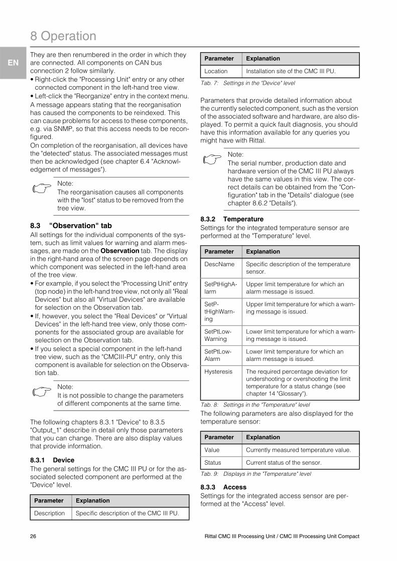
display in a shared window all parameter values of the lower-level entries to be changed.• Expand just the "CMC III PU" entry by clicking the"plus" character in front of this entry.• Place the mouse pointer at the end of the first col-
umn in the "Device" line.An "Edit" symbol appears and the mouse pointer changes to a "hand" symbol.
Fig. 33: Selecting several parameters
Legend1 Device entry2 "Edit" symbol
• Click the "Edit" symbol.The "Write Values" dialogue with the "Device.De-scription" and "Device.Location" parameters opens.
Fig. 34: "Write Values" dialogue with several parameters
• Specify the changed values for all required parame-ters.
• Click the Write button to confirm your inputs.The dialogue closes.
• Expand the "Device" entry by clicking the "plus" character in front of this entry.You can now view all changed values.
The "Write Values" dialogue shows all those parame-ters that can be changed below the previously select-ed level. For example, if you click the "Edit" symbol in the top "CMCIII-PU" level, all parameters that can be changed for the complete component will be dis-played.
8.2.7 Logout and changing the passwordFor each user group (and thus also for every user) a time can be specified after which the user will be logged out automatically in case of inactivity (see chapter 8.7 "Security"). A user can, however, also log out from the web user interface.• Click the Logout button on the right-hand side in the
upper area of the screen page.The logout is performed immediately and the Logout window opens.
Users can also change their own password in the web user interface.• Click the Password button on the right-hand side in
the upper area of the screen page.The "Set new password for user 'XXX'" dialogue opens.
Fig. 35: Changing the password
• Enter the new password in the "Password" line (at least three characters) and repeat it in the "Re-enter password" line.
When both entries match, you must use the new pass-word for the next login to the system.
8.2.8 Reorganising the connected componentsDuring the reinstallation of components on the CMC III PU, they are added at the next free position in the tree view and are given the appropriate ID number. In particular after several upgrades or changes to the order of the connected component, this can mean there is no longer any relationship be-tween the position of the components in the CAN bus and the corresponding ID number.The "Reorganize" function renumbers all connected components. The renumbering begins with the com-ponents on CAN bus connection 1 of the CMC III PU.
Note:An error message appears if too many var-iables are to be changed. In this case you must switch to the next lower level.
Note:Independent of this change, a user with the appropriate rights can change the pass-words of all users from the user administra-tion (see chapter 8.7.2 "Users").
Rittal CMC III Processing Unit / CMC III Processing Unit Compact 25
8 Operation
EN
They are then renumbered in the order in which they are connected. All components on CAN bus connection 2 follow similarly.• Right-click the "Processing Unit" entry or any otherconnected component in the left-hand tree view.• Left-click the "Reorganize" entry in the context menu.A message appears stating that the reorganisation has caused the components to be reindexed. This can cause problems for access to these components, e.g. via SNMP, so that this access needs to be recon-figured.On completion of the reorganisation, all devices have the "detected" status. The associated messages must then be acknowledged (see chapter 6.4 "Acknowl-edgement of messages").
8.3 "Observation" tabAll settings for the individual components of the sys-tem, such as limit values for warning and alarm mes-sages, are made on the Observation tab. The display in the right-hand area of the screen page depends on which component was selected in the left-hand area of the tree view.• For example, if you select the "Processing Unit" entry
(top node) in the left-hand tree view, not only all "Real Devices" but also all "Virtual Devices" are available for selection on the Observation tab.
• If, however, you select the "Real Devices" or "Virtual Devices" in the left-hand tree view, only those com-ponents for the associated group are available for selection on the Observation tab.
• If you select a special component in the left-hand tree view, such as the "CMCIII-PU" entry, only this component is available for selection on the Observa-tion tab.
The following chapters 8.3.1 "Device" to 8.3.5 "Output_1" describe in detail only those parameters that you can change. There are also display values that provide information.
8.3.1 DeviceThe general settings for the CMC III PU or for the as-sociated selected component are performed at the "Device" level.
Tab. 7: Settings in the "Device" level
Parameters that provide detailed information about the currently selected component, such as the version of the associated software and hardware, are also dis-played. To permit a quick fault diagnosis, you should have this information available for any queries you might have with Rittal.
8.3.2 TemperatureSettings for the integrated temperature sensor are performed at the "Temperature" level.
Tab. 8: Settings in the "Temperature" level
The following parameters are also displayed for the temperature sensor:
Tab. 9: Displays in the "Temperature" level
8.3.3 AccessSettings for the integrated access sensor are per-formed at the "Access" level.
Note:The reorganisation causes all components with the "lost" status to be removed from the tree view.
Note:It is not possible to change the parameters of different components at the same time.
Parameter Explanation
Description Specific description of the CMC III PU.
Location Installation site of the CMC III PU.
Note:The serial number, production date and hardware version of the CMC III PU always have the same values in this view. The cor-rect details can be obtained from the "Con-figuration" tab in the "Details" dialogue (see chapter 8.6.2 "Details").
Parameter Explanation
DescName Specific description of the temperature sensor.
SetPtHighA-larm
Upper limit temperature for which an alarm message is issued.
SetP-tHighWarn-ing
Upper limit temperature for which a warn-ing message is issued.
SetPtLow-Warning
Lower limit temperature for which a warn-ing message is issued.
SetPtLow-Alarm
Lower limit temperature for which an alarm message is issued.
Hysteresis The required percentage deviation for undershooting or overshooting the limit temperature for a status change (see chapter 14 "Glossary").
Parameter Explanation
Value Currently measured temperature value.
Status Current status of the sensor.
Parameter Explanation
26 Rittal CMC III Processing Unit / CMC III Processing Unit Compact
8 Operation
EN
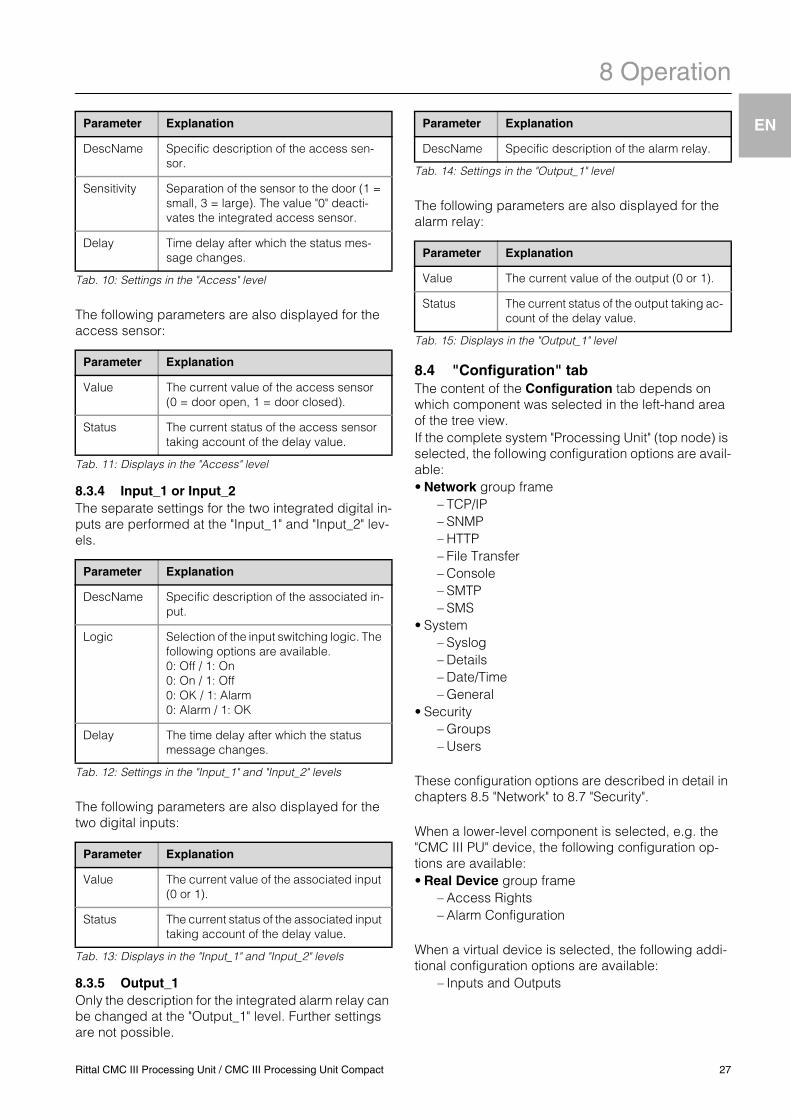
Tab. 10: Settings in the "Access" level
The following parameters are also displayed for the access sensor:
Tab. 11: Displays in the "Access" level
8.3.4 Input_1 or Input_2The separate settings for the two integrated digital in-puts are performed at the "Input_1" and "Input_2" lev-els.
Tab. 12: Settings in the "Input_1" and "Input_2" levels
The following parameters are also displayed for the two digital inputs:
Tab. 13: Displays in the "Input_1" and "Input_2" levels
8.3.5 Output_1Only the description for the integrated alarm relay can be changed at the "Output_1" level. Further settings are not possible.
Tab. 14: Settings in the "Output_1" level
The following parameters are also displayed for the alarm relay:
Tab. 15: Displays in the "Output_1" level
8.4 "Configuration" tabThe content of the Configuration tab depends on which component was selected in the left-hand area of the tree view. If the complete system "Processing Unit" (top node) is selected, the following configuration options are avail-able:• Network group frame
– TCP/IP– SNMP– HTTP– File Transfer– Console– SMTP– SMS
• System– Syslog– Details– Date/Time– General
• Security– Groups– Users
These configuration options are described in detail in chapters 8.5 "Network" to 8.7 "Security".
When a lower-level component is selected, e.g. the "CMC III PU" device, the following configuration op-tions are available:• Real Device group frame
– Access Rights– Alarm Configuration
When a virtual device is selected, the following addi-tional configuration options are available:
– Inputs and Outputs
Parameter Explanation
DescName Specific description of the access sen-sor.
Sensitivity Separation of the sensor to the door (1 = small, 3 = large). The value "0" deacti-vates the integrated access sensor.
Delay Time delay after which the status mes-sage changes.
Parameter Explanation
Value The current value of the access sensor (0 = door open, 1 = door closed).
Status The current status of the access sensor taking account of the delay value.
Parameter Explanation
DescName Specific description of the associated in-put.
Logic Selection of the input switching logic. The following options are available.0: Off / 1: On0: On / 1: Off0: OK / 1: Alarm0: Alarm / 1: OK
Delay The time delay after which the status message changes.
Parameter Explanation
Value The current value of the associated input (0 or 1).
Status The current status of the associated input taking account of the delay value.
Parameter Explanation
DescName Specific description of the alarm relay.
Parameter Explanation
Value The current value of the output (0 or 1).
Status The current status of the output taking ac-count of the delay value.
Rittal CMC III Processing Unit / CMC III Processing Unit Compact 27
8 Operation
EN
These configuration options are described in detail in chapters 8.8 "Access rights" to 8.10 "Inputs and out-puts".Irrespective of the selected component, the two but-tons in the upper area of the Configuration tab can be used to display (left-hand button) or print (right-hand button) a summary of the current settings.
8.5 Network
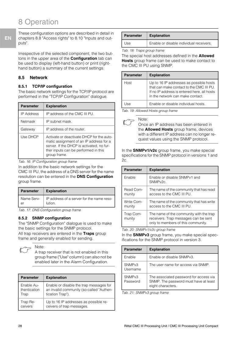
8.5.1 TCP/IP configurationThe basic network settings for the TCP/IP protocol are performed in the "TCP/IP Configuration" dialogue.
Tab. 16: IP Configuration group frame
In addition to the basic network settings for the CMC III PU, the address of a DNS server for the name resolution can be entered in the DNS Configuration group frame.
Tab. 17: DNS Configuration group frame
8.5.2 SNMP configurationThe "SNMP Configuration" dialogue is used to make the basic settings for the SNMP protocol.All trap receivers are entered in the Traps group frame and generally enabled for sending.
Tab. 18: Traps group frame
The special host addresses defined in the Allowed Hosts group frame can be used to make contact to the CMC III PU using SNMP.
Tab. 19: Allowed Hosts group frame
In the SNMPv1/v2c group frame, you make special specifications for the SNMP protocol in versions 1 and 2c.
Tab. 20: SNMPv1/v2c group frame
In the SNMPv3 group frame, you make special spec-ifications for the SNMP protocol in version 3.
Tab. 21: SNMPv3 group frame
Parameter Explanation
IP Address IP address of the CMC III PU.
Netmask IP subnet mask.
Gateway IP address of the router.
Use DHCP Activate or deactivate DHCP for the auto-matic assignment of an IP address for a server. If the DHCP is activated, no fur-ther inputs can be performed in this group frame.
Parameter Explanation
Name Serv-er
IP address of a server for the name reso-lution.
Note:A trap receiver that is not enabled in this group frame ("Use" column) can also not be enabled later in the Alarm Configuration.
Parameter Explanation
Enable Au-thentication Trap
Enable or disable the trap messages for an invalid community (so-called "Authen-tication Trap").
Trap Re-ceivers
Up to 16 IP addresses as possible re-ceivers of trap messages.
Use Enable or disable individual receivers.
Parameter Explanation
Host Up to 16 IP addresses as possible hosts that can make contact to the CMC III PU. If no IP address is entered here, all hosts in the network can make contact.
Use Enable or disable individual hosts.
Note:Once an IP address has been entered in the Allowed Hosts group frame, devices with a different IP address can no longer re-quest values using the SNMP protocol.
Parameter Explanation
Enable Enable or disable SNMPv1 and SNMPv2c.
Read Com-munity
The name of the community that has read access to the CMC III PU.
Write Com-munity
The name of the community that has write access to the CMC III PU.
Trap Com-munity
The name of the community with the trap receivers. Trap messages can be sent only to members of this community.
Parameter Explanation
Enable Enable or disable SNMPv3.
SNMPv3 Username
The user name for access via SNMP.
SNMPv3 Password
The associated password for access via SNMP. The password must have at least eight characters.
Parameter Explanation
28 Rittal CMC III Processing Unit / CMC III Processing Unit Compact
8 Operation
EN
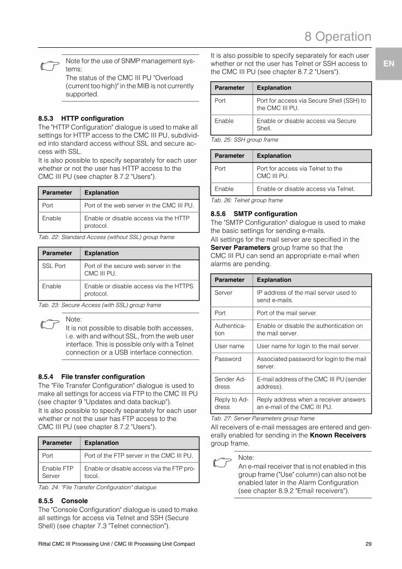
8.5.3 HTTP configurationThe "HTTP Configuration" dialogue is used to make all settings for HTTP access to the CMC III PU, subdivid-ed into standard access without SSL and secure ac-cess with SSL.It is also possible to specify separately for each user whether or not the user has HTTP access to the CMC III PU (see chapter 8.7.2 "Users").
Tab. 22: Standard Access (without SSL) group frame
Tab. 23: Secure Access (with SSL) group frame
8.5.4 File transfer configurationThe "File Transfer Configuration" dialogue is used to make all settings for access via FTP to the CMC III PU (see chapter 9 "Updates and data backup").It is also possible to specify separately for each user whether or not the user has FTP access to the CMC III PU (see chapter 8.7.2 "Users").
Tab. 24: "File Transfer Configuration" dialogue
8.5.5 ConsoleThe "Console Configuration" dialogue is used to make all settings for access via Telnet and SSH (Secure Shell) (see chapter 7.3 "Telnet connection").
It is also possible to specify separately for each user whether or not the user has Telnet or SSH access to the CMC III PU (see chapter 8.7.2 "Users").
Tab. 25: SSH group frame
Tab. 26: Telnet group frame
8.5.6 SMTP configurationThe "SMTP Configuration" dialogue is used to make the basic settings for sending e-mails.All settings for the mail server are specified in the Server Parameters group frame so that the CMC III PU can send an appropriate e-mail when alarms are pending.
Tab. 27: Server Parameters group frame
All receivers of e-mail messages are entered and gen-erally enabled for sending in the Known Receivers group frame.
Note for the use of SNMP management sys-tems:The status of the CMC III PU "Overload (current too high)" in the MIB is not currently supported.
Parameter Explanation
Port Port of the web server in the CMC III PU.
Enable Enable or disable access via the HTTP protocol.
Parameter Explanation
SSL Port Port of the secure web server in the CMC III PU.
Enable Enable or disable access via the HTTPS protocol.
Note:It is not possible to disable both accesses, i.e. with and without SSL, from the web user interface. This is possible only with a Telnet connection or a USB interface connection.
Parameter Explanation
Port Port of the FTP server in the CMC III PU.
Enable FTP Server
Enable or disable access via the FTP pro-tocol.
Parameter Explanation
Port Port for access via Secure Shell (SSH) to the CMC III PU.
Enable Enable or disable access via Secure Shell.
Parameter Explanation
Port Port for access via Telnet to the CMC III PU.
Enable Enable or disable access via Telnet.
Parameter Explanation
Server IP address of the mail server used to send e-mails.
Port Port of the mail server.
Authentica-tion
Enable or disable the authentication on the mail server.
User name User name for login to the mail server.
Password Associated password for login to the mail server.
Sender Ad-dress
E-mail address of the CMC III PU (sender address).
Reply to Ad-dress
Reply address when a receiver answers an e-mail of the CMC III PU.
Note:An e-mail receiver that is not enabled in this group frame ("Use" column) can also not be enabled later in the Alarm Configuration (see chapter 8.9.2 "Email receivers").
Rittal CMC III Processing Unit / CMC III Processing Unit Compact 29
8 Operation
EN
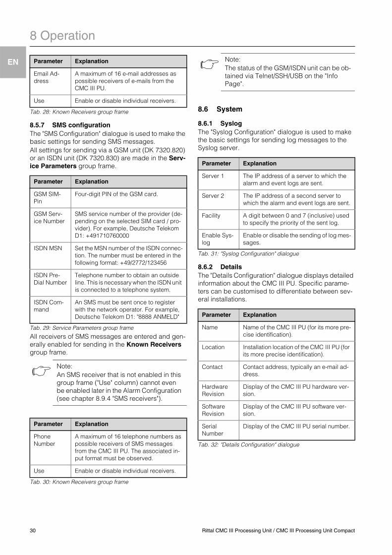
Tab. 28: Known Receivers group frame
8.5.7 SMS configurationThe "SMS Configuration" dialogue is used to make the basic settings for sending SMS messages.All settings for sending via a GSM unit (DK 7320.820) or an ISDN unit (DK 7320.830) are made in the Serv-ice Parameters group frame.
Tab. 29: Service Parameters group frame
All receivers of SMS messages are entered and gen-erally enabled for sending in the Known Receivers group frame.
Tab. 30: Known Receivers group frame
8.6 System
8.6.1 SyslogThe "Syslog Configuration" dialogue is used to make the basic settings for sending log messages to the Syslog server.
Tab. 31: "Syslog Configuration" dialogue
8.6.2 DetailsThe "Details Configuration" dialogue displays detailed information about the CMC III PU. Specific parame-ters can be customised to differentiate between sev-eral installations.
Tab. 32: "Details Configuration" dialogue
Parameter Explanation
Email Ad-dress
A maximum of 16 e-mail addresses as possible receivers of e-mails from the CMC III PU.
Use Enable or disable individual receivers.
Parameter Explanation
GSM SIM-Pin
Four-digit PIN of the GSM card.
GSM Serv-ice Number
SMS service number of the provider (de-pending on the selected SIM card / pro-vider). For example, Deutsche Telekom D1: +491710760000
ISDN MSN Set the MSN number of the ISDN connec-tion. The number must be entered in the following format: +49/2772/123456
ISDN Pre-Dial Number
Telephone number to obtain an outside line. This is necessary when the ISDN unit is connected to a telephone system.
ISDN Com-mand
An SMS must be sent once to register with the network operator. For example, Deutsche Telekom D1: "8888 ANMELD"
Note:An SMS receiver that is not enabled in this group frame ("Use" column) cannot even be enabled later in the Alarm Configuration (see chapter 8.9.4 "SMS receivers").
Parameter Explanation
Phone Number
A maximum of 16 telephone numbers as possible receivers of SMS messages from the CMC III PU. The associated in-put format must be observed.
Use Enable or disable individual receivers.
Note:The status of the GSM/ISDN unit can be ob-tained via Telnet/SSH/USB on the "Info Page".
Parameter Explanation
Server 1 The IP address of a server to which the alarm and event logs are sent.
Server 2 The IP address of a second server to which the alarm and event logs are sent.
Facility A digit between 0 and 7 (inclusive) used to specify the priority of the sent log.
Enable Sys-log
Enable or disable the sending of log mes-sages.
Parameter Explanation
Name Name of the CMC III PU (for its more pre-cise identification).
Location Installation location of the CMC III PU (for its more precise identification).
Contact Contact address, typically an e-mail ad-dress.
Hardware Revision
Display of the CMC III PU hardware ver-sion.
Software Revision
Display of the CMC III PU software ver-sion.
Serial Number
Display of the CMC III PU serial number.
30 Rittal CMC III Processing Unit / CMC III Processing Unit Compact
8 Operation
EN
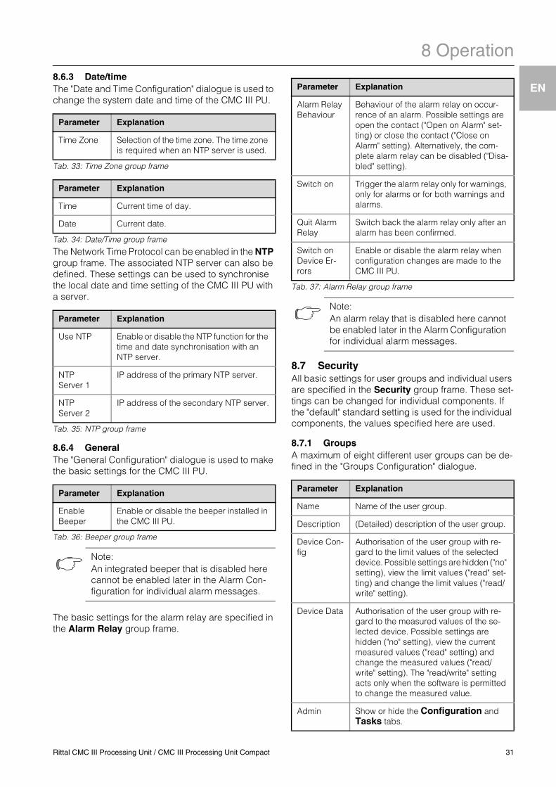
8.6.3 Date/timeThe "Date and Time Configuration" dialogue is used to change the system date and time of the CMC III PU.Tab. 33: Time Zone group frame
Tab. 34: Date/Time group frame
The Network Time Protocol can be enabled in the NTP group frame. The associated NTP server can also be defined. These settings can be used to synchronise the local date and time setting of the CMC III PU with a server.
Tab. 35: NTP group frame
8.6.4 GeneralThe "General Configuration" dialogue is used to make the basic settings for the CMC III PU.
Tab. 36: Beeper group frame
The basic settings for the alarm relay are specified in the Alarm Relay group frame.
Tab. 37: Alarm Relay group frame
8.7 SecurityAll basic settings for user groups and individual users are specified in the Security group frame. These set-tings can be changed for individual components. If the "default" standard setting is used for the individual components, the values specified here are used.
8.7.1 GroupsA maximum of eight different user groups can be de-fined in the "Groups Configuration" dialogue.
Parameter Explanation
Time Zone Selection of the time zone. The time zone is required when an NTP server is used.
Parameter Explanation
Time Current time of day.
Date Current date.
Parameter Explanation
Use NTP Enable or disable the NTP function for the time and date synchronisation with an NTP server.
NTP Server 1
IP address of the primary NTP server.
NTP Server 2
IP address of the secondary NTP server.
Parameter Explanation
Enable Beeper
Enable or disable the beeper installed in the CMC III PU.
Note:An integrated beeper that is disabled here cannot be enabled later in the Alarm Con-figuration for individual alarm messages.
Parameter Explanation
Alarm Relay Behaviour
Behaviour of the alarm relay on occur-rence of an alarm. Possible settings are open the contact ("Open on Alarm" set-ting) or close the contact ("Close on Alarm" setting). Alternatively, the com-plete alarm relay can be disabled ("Disa-bled" setting).
Switch on Trigger the alarm relay only for warnings, only for alarms or for both warnings and alarms.
Quit Alarm Relay
Switch back the alarm relay only after an alarm has been confirmed.
Switch on Device Er-rors
Enable or disable the alarm relay when configuration changes are made to the CMC III PU.
Note:An alarm relay that is disabled here cannot be enabled later in the Alarm Configuration for individual alarm messages.
Parameter Explanation
Name Name of the user group.
Description (Detailed) description of the user group.
Device Con-fig
Authorisation of the user group with re-gard to the limit values of the selected device. Possible settings are hidden ("no" setting), view the limit values ("read" set-ting) and change the limit values ("read/write" setting).
Device Data Authorisation of the user group with re-gard to the measured values of the se-lected device. Possible settings are hidden ("no" setting), view the current measured values ("read" setting) and change the measured values ("read/write" setting). The "read/write" setting acts only when the software is permitted to change the measured value.
Admin Show or hide the Configuration and Tasks tabs.
Rittal CMC III Processing Unit / CMC III Processing Unit Compact 31
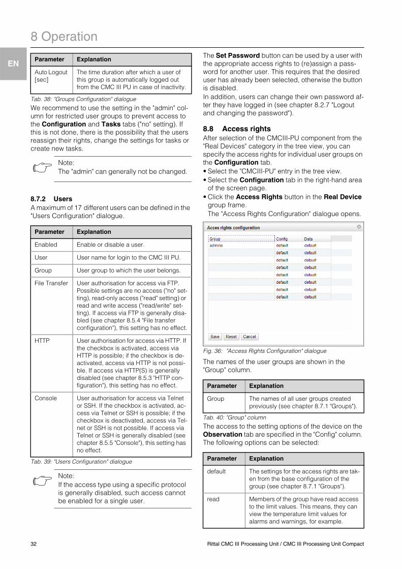
8 Operation
EN
Tab. 38: "Groups Configuration" dialogue
We recommend to use the setting in the "admin" col-umn for restricted user groups to prevent access to the Configuration and Tasks tabs ("no" setting). If this is not done, there is the possibility that the users reassign their rights, change the settings for tasks or create new tasks.
8.7.2 UsersA maximum of 17 different users can be defined in the "Users Configuration" dialogue.
Tab. 39: "Users Configuration" dialogue
The Set Password button can be used by a user with the appropriate access rights to (re)assign a pass-word for another user. This requires that the desired user has already been selected, otherwise the button is disabled.In addition, users can change their own password af-ter they have logged in (see chapter 8.2.7 "Logout and changing the password").
8.8 Access rightsAfter selection of the CMCIII-PU component from the "Real Devices" category in the tree view, you can specify the access rights for individual user groups on the Configuration tab.• Select the "CMCIII-PU" entry in the tree view.• Select the Configuration tab in the right-hand area
of the screen page.• Click the Access Rights button in the Real Device
group frame.The "Access Rights Configuration" dialogue opens.
Fig. 36: "Access Rights Configuration" dialogue
The names of the user groups are shown in the "Group" column.
Tab. 40: "Group" column
The access to the setting options of the device on the Observation tab are specified in the "Config" column. The following options can be selected:
Auto Logout [sec]
The time duration after which a user of this group is automatically logged out from the CMC III PU in case of inactivity.
Note:The "admin" can generally not be changed.
Parameter Explanation
Enabled Enable or disable a user.
User User name for login to the CMC III PU.
Group User group to which the user belongs.
File Transfer User authorisation for access via FTP. Possible settings are no access ("no" set-ting), read-only access ("read" setting) or read and write access ("read/write" set-ting). If access via FTP is generally disa-bled (see chapter 8.5.4 "File transfer configuration"), this setting has no effect.
HTTP User authorisation for access via HTTP. If the checkbox is activated, access via HTTP is possible; if the checkbox is de-activated, access via HTTP is not possi-ble. If access via HTTP(S) is generally disabled (see chapter 8.5.3 "HTTP con-figuration"), this setting has no effect.
Console User authorisation for access via Telnet or SSH. If the checkbox is activated, ac-cess via Telnet or SSH is possible; if the checkbox is deactivated, access via Tel-net or SSH is not possible. If access via Telnet or SSH is generally disabled (see chapter 8.5.5 "Console"), this setting has no effect.
Note:If the access type using a specific protocol is generally disabled, such access cannot be enabled for a single user.
Parameter Explanation
Parameter Explanation
Group The names of all user groups created previously (see chapter 8.7.1 "Groups").
Parameter Explanation
default The settings for the access rights are tak-en from the base configuration of the group (see chapter 8.7.1 "Groups").
read Members of the group have read access to the limit values. This means, they can view the temperature limit values for alarms and warnings, for example.
32 Rittal CMC III Processing Unit / CMC III Processing Unit Compact
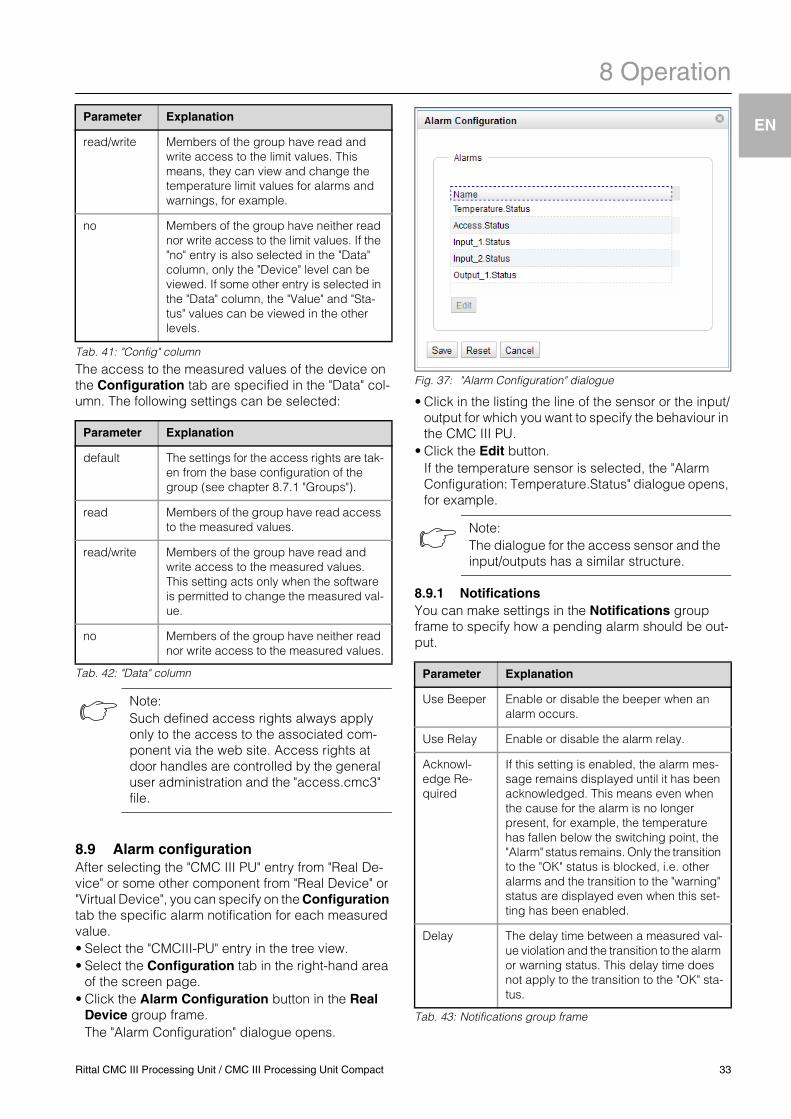
8 Operation
EN
Tab. 41: "Config" column
The access to the measured values of the device on the Configuration tab are specified in the "Data" col-umn. The following settings can be selected:
Tab. 42: "Data" column
8.9 Alarm configurationAfter selecting the "CMC III PU" entry from "Real De-vice" or some other component from "Real Device" or "Virtual Device", you can specify on the Configuration tab the specific alarm notification for each measured value.• Select the "CMCIII-PU" entry in the tree view.• Select the Configuration tab in the right-hand area
of the screen page.• Click the Alarm Configuration button in the Real
Device group frame.The "Alarm Configuration" dialogue opens.
Fig. 37: "Alarm Configuration" dialogue
• Click in the listing the line of the sensor or the input/output for which you want to specify the behaviour in the CMC III PU.
• Click the Edit button.If the temperature sensor is selected, the "Alarm Configuration: Temperature.Status" dialogue opens, for example.
8.9.1 NotificationsYou can make settings in the Notifications group frame to specify how a pending alarm should be out-put.
Tab. 43: Notifications group frame
read/write Members of the group have read and write access to the limit values. This means, they can view and change the temperature limit values for alarms and warnings, for example.
no Members of the group have neither read nor write access to the limit values. If the "no" entry is also selected in the "Data" column, only the "Device" level can be viewed. If some other entry is selected in the "Data" column, the "Value" and "Sta-tus" values can be viewed in the other levels.
Parameter Explanation
default The settings for the access rights are tak-en from the base configuration of the group (see chapter 8.7.1 "Groups").
read Members of the group have read access to the measured values.
read/write Members of the group have read and write access to the measured values. This setting acts only when the software is permitted to change the measured val-ue.
no Members of the group have neither read nor write access to the measured values.
Note:Such defined access rights always apply only to the access to the associated com-ponent via the web site. Access rights at door handles are controlled by the general user administration and the "access.cmc3" file.
Parameter Explanation
Note:The dialogue for the access sensor and the input/outputs has a similar structure.
Parameter Explanation
Use Beeper Enable or disable the beeper when an alarm occurs.
Use Relay Enable or disable the alarm relay.
Acknowl-edge Re-quired
If this setting is enabled, the alarm mes-sage remains displayed until it has been acknowledged. This means even when the cause for the alarm is no longer present, for example, the temperature has fallen below the switching point, the "Alarm" status remains. Only the transition to the "OK" status is blocked, i.e. other alarms and the transition to the "warning" status are displayed even when this set-ting has been enabled.
Delay The delay time between a measured val-ue violation and the transition to the alarm or warning status. This delay time does not apply to the transition to the "OK" sta-tus.
Rittal CMC III Processing Unit / CMC III Processing Unit Compact 33
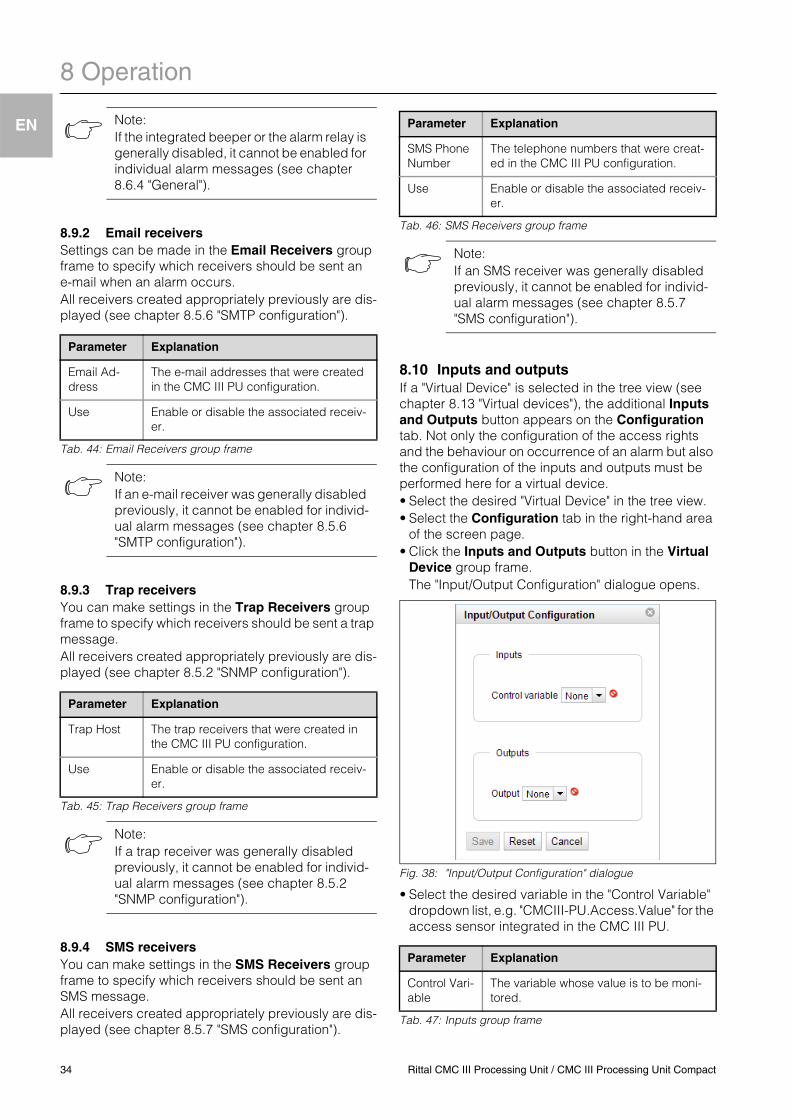
8 Operation
EN
8.9.2 Email receiversSettings can be made in the Email Receivers group frame to specify which receivers should be sent an e-mail when an alarm occurs.All receivers created appropriately previously are dis-played (see chapter 8.5.6 "SMTP configuration").
Tab. 44: Email Receivers group frame
8.9.3 Trap receiversYou can make settings in the Trap Receivers group frame to specify which receivers should be sent a trap message.All receivers created appropriately previously are dis-played (see chapter 8.5.2 "SNMP configuration").
Tab. 45: Trap Receivers group frame
8.9.4 SMS receiversYou can make settings in the SMS Receivers group frame to specify which receivers should be sent an SMS message.All receivers created appropriately previously are dis-played (see chapter 8.5.7 "SMS configuration").
Tab. 46: SMS Receivers group frame
8.10 Inputs and outputsIf a "Virtual Device" is selected in the tree view (see chapter 8.13 "Virtual devices"), the additional Inputs and Outputs button appears on the Configuration tab. Not only the configuration of the access rights and the behaviour on occurrence of an alarm but also the configuration of the inputs and outputs must be performed here for a virtual device.• Select the desired "Virtual Device" in the tree view.• Select the Configuration tab in the right-hand area
of the screen page.• Click the Inputs and Outputs button in the Virtual
Device group frame.The "Input/Output Configuration" dialogue opens.
Fig. 38: "Input/Output Configuration" dialogue
• Select the desired variable in the "Control Variable" dropdown list, e.g. "CMCIII-PU.Access.Value" for the access sensor integrated in the CMC III PU.
Tab. 47: Inputs group frame
Note:If the integrated beeper or the alarm relay is generally disabled, it cannot be enabled for individual alarm messages (see chapter 8.6.4 "General").
Parameter Explanation
Email Ad-dress
The e-mail addresses that were created in the CMC III PU configuration.
Use Enable or disable the associated receiv-er.
Note:If an e-mail receiver was generally disabled previously, it cannot be enabled for individ-ual alarm messages (see chapter 8.5.6 "SMTP configuration").
Parameter Explanation
Trap Host The trap receivers that were created in the CMC III PU configuration.
Use Enable or disable the associated receiv-er.
Note:If a trap receiver was generally disabled previously, it cannot be enabled for individ-ual alarm messages (see chapter 8.5.2 "SNMP configuration").
Parameter Explanation
SMS Phone Number
The telephone numbers that were creat-ed in the CMC III PU configuration.
Use Enable or disable the associated receiv-er.
Note:If an SMS receiver was generally disabled previously, it cannot be enabled for individ-ual alarm messages (see chapter 8.5.7 "SMS configuration").
Parameter Explanation
Control Vari-able
The variable whose value is to be moni-tored.
34 Rittal CMC III Processing Unit / CMC III Processing Unit Compact
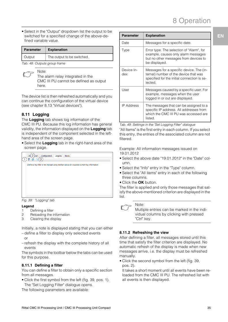
8 Operation
EN
• Select in the "Output" dropdown list the output to beswitched for a specified change of the above-de-fined variable value.
Tab. 48: Outputs group frame
The device list is then refreshed automatically and you can continue the configuration of the virtual device (see chapter 8.13 "Virtual devices").
8.11 LoggingThe Logging tab shows log information of the CMC III PU. Because this log information has general validity, the information displayed on the Logging tab is independent of the component selected in the left-hand area of the screen page.• Select the Logging tab in the right-hand area of the
screen page.
Fig. 39: "Logging" tab
Legend1 Defining a filter2 Reloading the information3 Clearing the display
Initially, a note is displayed stating that you can either– define a filter to display only selected events
or– refresh the display with the complete history of all
eventsThe symbols in the toolbar below the tabs can be used for this purpose.
8.11.1 Defining a filterYou can define a filter to obtain only a specific section from all messages.• Click the first symbol from the left (fig. 39, pos. 1).
The "Set Logging Filter" dialogue opens.The following parameters are available:
Tab. 49: Settings in the "Set Logging Filter" dialogue
"All Items" is the first entry in each column. If you select this entry, the entries of the associated column are not filtered.
Example: All information messages issued on 19.01.2012• Select the above date "19.01.2012" in the "Date" col-
umn.• Select the "Info" entry in the "Type" column.• Select the "All items" entry in each of the following
three columns.• Click the OK button.The filter is applied and only those messages that sat-isfy the above-mentioned criterion are displayed in the list.
8.11.2 Refreshing the viewAfter defining a filter, all messages stored until this time that satisfy the filter criterion are displayed. No automatic refresh of the display is made when new messages arrive, i.e. the display must be refreshed manually.• Click the second symbol from the left (fig. 39,
pos. 2).It takes a short moment until all events have been re-loaded from the CMC III PU. The refreshed list with all events is then displayed.
Parameter Explanation
Output The output to be switched.
Note:The alarm relay integrated in the CMC III PU cannot be defined as output here.
Parameter Explanation
Date Messages for a specific date.
Type Error type. The selection of "Alarm", for example, causes only alarm messages but no other messages from devices to be displayed.
Device In-dex
Messages for a specific device. The (in-ternal) number of the device that was specified for the initial connection is se-lected.
User Messages caused by a specific user. For example, messages when the user logged in or out are displayed.
IP Address The messages that can be assigned to a specific IP address. All addresses from which the CMC III PU was accessed are listed.
Note:Multiple entries can be marked in the indi-vidual columns by clicking with pressed "Ctrl" key.
Rittal CMC III Processing Unit / CMC III Processing Unit Compact 35
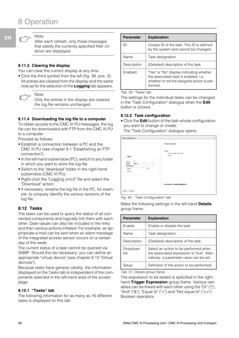
8 Operation
EN
8.11.3 Clearing the displayYou can clear the current display at any time.• Click the third symbol from the left (fig. 39, pos. 3).
All entries are cleared from the display and the same note as for the selection of the Logging tab appears.
8.11.4 Downloading the log file to a computerTo obtain access to the CMC III PU messages, the log file can be downloaded with FTP from the CMC III PU to a computer.Proceed as follows:• Establish a connection between a PC and the
CMC III PU (see chapter 9.1 "Establishing an FTP connection").
• In the left-hand subwindow (PC), switch to any folder in which you want to store the log file.
• Switch to the "download" folder in the right-hand subwindow (CMC III PU).
• Right-click the "Logging.cmc3" file and select the "Download" action.
• If necessary, rename the log file in the PC, for exam-ple, to uniquely identify the various versions of the log file.
8.12 TasksThe tasks can be used to query the status of all con-nected components and logically link them with each other. Date values can also be included in the links and then various actions initiated. For example, an ap-propriate e-mail can be sent when an alarm message of the integrated access sensor occurs on a certain day of the week.The current status of a task cannot be queried via SNMP. Should this be necessary, you can define an appropriate "virtual device" (see chapter 8.13 "Virtual devices").Because tasks have general validity, the information displayed on the Tasks tab is independent of the com-ponents selected in the left-hand area of the screen page.
8.12.1 "Tasks" tabThe following information for as many as 16 different tasks is displayed on this tab:
Tab. 50: "Tasks" tab
The settings for the individual tasks can be changed in the "Task Configuration" dialogue when the Edit button is clicked.
8.12.2 Task configuration• Click the Edit button of the task whose configuration
you want to change or create.The "Task Configuration" dialogue opens.
Fig. 40: "Task Configuration" tab
Make the following settings in the left-hand Details group frame:
Tab. 51: Details group frame
The expression to be tested is specified in the right-hand Trigger Expression group frame. Various vari-ables can be linked with each other using the "Or" ("|"), "And" ("&"), "Equal to" ("=") and "Not equal to" ("<>") Boolean operators.
Note:After each refresh, only those messages that satisfy the currently specified filter cri-terion are displayed.
Note:Only the entries in the display are cleared, the log file remains unchanged.
Parameter Explanation
ID Unique ID of the task. This ID is defined by the system and cannot be changed.
Name Task designation.
Description (Detailed) description of the task.
Enabled "Yes" or "No" display indicating whether the associated task is enabled, i.e. whether or not the assigned action is per-formed.
Parameter Explanation
Enable Enable or disable the task.
Name Task designation.
Description (Detailed) description of the task.
Dropdown list
Select an action to be performed when the associated expression is "true". Alter-natively, a parameter value can be set.
Setup Definition of the action to be performed.
36 Rittal CMC III Processing Unit / CMC III Processing Unit Compact
8 Operation
EN
Tab. 52: Trigger Expression group frame
The dropdown lists for selection of the various setting options are displayed after clicking one of the prede-fined values "=", "No Variable Selected" or "0" (refer to the example in this section).The "=" and "<>" operators can be used to test varia-bles of the CMC III PU or of the connected devices whether they have a specific value. As an alternative, date details (day of week) can be tested.The "|" and "&" operators can be used to link subordi-nate expressions with each other.Proceed as follows to define an expression:• When several expressions should be tested: First
specify whether the two subordinate expressions must both return the "true" value ("&" operator) or just one value suffices to initiate the action ("|" operator).
• Specify separately for all subordinate expressions whether the specified event is initiated when the var-iable or the date value matches the value ("=" oper-ator) or not ("<>" operator).
The complete expression is shown again in plain text at the lower edge of the Trigger Expression group frame.• Finally, assign to the task from the dropdown list the
action to be performed when the complete expres-sion returns the value "true".
You can choose between the following settings:
Tab. 53: Details group frame
After the selection of the desired action, it must be configured appropriately.• To do this, click the Setup button.Depending on the previously selected action, specify in the appropriate dialogue, for example, who should be sent a status e-mail ("Send Status Email" action), for which status an alarm message should be sup-pressed ("Suppress Alarm Message" action), etc.
If the "Set Variable Value" action is selected, "switcha-ble" variables (such as the digital outputs of a con-nected IO unit) can be set.
Example: An enclosure that opens at the weekendYou want to define a task that sends an alarm e-mail when an enclosure is opened at the weekend.• Click the "=" operator displayed by default in order to
display the "Operator Type" dropdown list.• Select the "&" operator in this dropdown list in order
to link the "weekend" and "door open" events with each other.
• Click the "No Variable Selected" entry below the first "=" operator.
• Select the "Time" entry in the "Nature" dropdown list.• Click the first entry, "Never".• Select the "Saturday" entry in the "Day of Week" list
box.• While keeping the "Ctrl" key pressed, also select the
"Sunday" entry in this list.• Click the "No Variable Selected" entry below the sec-
ond "=" operator.• Select the "Variable" entry (preselected by default) in
the "Nature" dropdown list.• Select the "[1] CMCIII-PU" entry in the "Device" drop-
down list.
Parameter Explanation
Operator Type
The Boolean operator with which the as-signed expressions are linked or the var-iables tested.
Nature Selection of the "Time" specification for testing a specified time or "Variable" for testing a variable value.
Device Selection of the device for which a value should be tested.
Variable The variable whose value is to be tested. This list shows only those variables avail-able for the previously selected device.
Value Value for which the variable is to be test-ed. This list shows only those values available for the previously selected vari-able.
Parameter Explanation
Send Status Email
Send a status e-mail.
Send Status SMS
Send a status SMS.
Suppress Alarm Email
Suppress the sending of e-mails to se-lected receivers.
Suppress Alarm SMS
Suppress the sending of SMS messages to selected receivers.
Suppress Alarm Trap
Suppress the sending of traps to select-ed receivers.
Suppress Alarm Mes-sage
Suppress the alarm message of the se-lected status.
Set Variable Value
Set a variable value.
Note:The CMC III PU is selected by default in the "Config Set Variable Value" dialogue. You must first select from the "Device" drop-down list a device with a switchable varia-ble so that the associated selection options are displayed in the fields below.
Parameter Explanation
Rittal CMC III Processing Unit / CMC III Processing Unit Compact 37
8 Operation
EN
• Select the "Access.Status" entry in the "Variable"dropdown list.• Click the "null" entry below the "[1] Access.Status"
variable.• Select the "Open" entry in the "Value" dropdown list.The following expression is now displayed below in the Trigger Expression group frame:Expression: ( (Day of Week=Sa, Su) & ([1] Ac-cess.Status=Open) ) • Now select the "Send Status Email" entry as action in
the dropdown list in the Details group frame.• Click the Setup button to specify the desired receiv-
er for the status e-mail.
8.13 Virtual devicesThe so-called "Virtual Devices" are displayed in the left-hand area of the screen page below the "Real De-vices", i.e. the devices actually connected to the CMC III PU. These must first have been created using the "Configuration" tabs on the right-hand side.The sensors and the output devices can be coupled to form a new, predefined type of "Virtual Device". This allows, for example, when a prespecified temperature measured with the integrated temperature sensor is exceeded, a fan attached to a power unit (DK 7030.050) to be switched on.A virtual device is treated like an independent compo-nent for which, for example, the status can also be queried using SNMP. Although such a status query is not possible for a task, tasks can be better configured (see chapter 8.12 "Tasks").
8.13.1 Types of virtual devicesYou can select a two-level controller as virtual device. With the help of such a controller, it is possible to use a specified (threshold) value (e.g. a limit temperature) to switch an output on or off (e.g. an output of a con-nected IO unit). The above-mentioned (threshold) val-ue is specified directly in the virtual device and is in-dependent of the limit values defined in the actual sensor.
8.13.2 Creating a virtual deviceYou create a virtual device on the "Configuration" tab. To do this:• Select the "Virtual Devices" entry in the selection tree
in the left-hand area of the screen page.• Click the "Configuration" tab in the right-hand area of
the screen page.• Click the New tab in the List of Virtual Devices
group frame.• Select the desired type of virtual device in the "Virtual
Device Type" dropdown list in the "Create new virtual device" dialogue (e.g. "Two-Level Controller").
• Click the OK button to confirm your selection.Finally, the configuration change causes the list of all devices to be refreshed automatically. A new com-ponent, such as the above-mentioned "Two-Level
Controller", marked with a small green "+" character, appears under the "Virtual Devices" in the selection tree. The multi-LED of the CMC III PU flashes cycli-cally green – orange – red.
• Confirm the message for the configuration change (see chapter 6.4 "Acknowledgement of messages").The device list is refreshed automatically. The entry under the "Virtual Devices" now has a yellow back-ground and the LED of the CMC III PU lights orange continually provided no other alarm is pending.
• Finally, configure the inputs and outputs of the virtual device (see chapter 8.10 "Inputs and outputs").The device list is then refreshed automatically. A blue "information" symbol is displayed in the entry under the "Virtual Devices" and the LED of the CMC III PU lights green continually provided no oth-er alarm is pending.
• Select the appropriate "virtual device" in the selec-tion tree in the left-hand area of the screen page.
• Click the "Observation" tab to make the settings.• Click the Edit button.
The "Write Values" dialogue is displayed.• If necessary, change the individual settings.
8.13.3 Deleting a virtual deviceThe deletion of a virtual device is performed on the "Configuration" tab. To do this:• Select the "Virtual Devices" entry in the selection tree
in the left-hand area of the screen page.• Click the "Configuration" tab in the right-hand area of
the screen page.• Select the virtual device to be deleted in the List of
Virtual Devices group frame.• To delete further virtual devices, select them while
keeping the "Ctrl" key pressed.• Click the Delete button.
A prompt appears asking whether the virtual device really should be deleted.
• Confirm the deletion by clicking the OK button or cancel the deletion by clicking the Cancel button.
• Finally, confirm the message for the configuration change (see chapter 6.4 "Acknowledgement of messages").
Note:The displayed parameters depend on the "virtual device" type as well as on the input value to be monitored and the output to be switched.
38 Rittal CMC III Processing Unit / CMC III Processing Unit Compact
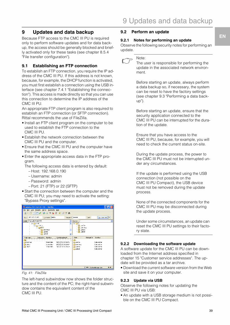
9 Updates and data backup
EN
9 Updates and data backupBecause FTP access to the CMC III PU is required only to perform software updates and for data back-up, the access should be generally blocked and brief-ly activated only for these tasks (see chapter 8.5.4 "File transfer configuration").9.1 Establishing an FTP connectionTo establish an FTP connection, you require the IP ad-dress of the CMC III PU. If this address is not known, because, for example, the DHCP function is activated, you must first establish a connection using the USB in-terface (see chapter 7.4.1 "Establishing the connec-tion"). This access is made directly so that you can use this connection to determine the IP address of the CMC III PU.An appropriate FTP client program is also required to establish an FTP connection (or SFTP connection). Rittal recommends the use of FileZilla.• Install an FTP client program on the computer to be
used to establish the FTP connection to the CMC III PU.
• Establish the network connection between the CMC III PU and the computer.
• Ensure that the CMC III PU and the computer have the same address space.
• Enter the appropriate access data in the FTP pro-gram.The following access data is entered by default:
– Host: 192.168.0.190– Username: admin– Password: admin– Port: 21 (FTP) or 22 (SFTP)
• Start the connection between the computer and the CMC III PU; you may need to activate the setting: "Bypass Proxy settings".
Fig. 41: FileZilla
The left-hand subwindow now shows the folder struc-ture and the content of the PC; the right-hand subwin-dow contains the equivalent content of the CMC III PU.
9.2 Perform an update
9.2.1 Notes for performing an updateObserve the following security notes for performing an update.
9.2.2 Downloading the software updateA software update for the CMC III PU can be down-loaded from the Internet address specified in chapter 15 "Customer service addresses". The up-date will be provided as a tar archive.• Download the current software version from the Web
site and save it on your computer.
9.2.3 Update via USBObserve the following notes for updating the CMC III PU via USB:• An update with a USB storage medium is not possi-
ble on the CMC III PU Compact.
Note:The user is responsible for performing the update in the associated network environ-ment.
Before starting an update, always perform a data backup so, if necessary, the system can be reset to have the factory settings (see chapter 9.3 "Performing a data back-up").
Before starting an update, ensure that the security application connected to the CMC III PU can be interrupted for the dura-tion of the update.
Ensure that you have access to the CMC III PU, because, for example, you will need to check the current status on-site.
During the update process, the power to the CMC III PU must not be interrupted un-der any circumstances.
If the update is performed using the USB connection (not possible on the CMC III PU Compact), the USB device must not be removed during the update process.
None of the connected components for the CMC III PU may be disconnected during the update process.
Under some circumstances, an update can reset the CMC III PU settings to their facto-ry state.
Rittal CMC III Processing Unit / CMC III Processing Unit Compact 39
9 Updates and data backup
EN
• The USB storage medium used for the update mustbe formatted as FAT.• In addition to the file for the software update, any
other data may be present on the USB storage me-dium.
Proceed as follows to perform the update:• Copy the downloaded tar file into the root directory
of the USB storage medium.• Start the CMC III PU if necessary. • Wait until the multi-LED on the front side lights green,
orange or red continually or is flashing.• Then insert the USB storage medium in the appropri-
ate USB slot at the rear of the CMC III PU.The update process starts automatically after a few minutes. This is indicated with a red flashing of the multi-LED (so-called heartbeat, alternately long and short).If the current software version (or a later version) is al-ready installed on the CMC III PU, no update will be performed.Depending on the number of connected sensors that are also updated, the complete update process takes approx. 15 minutes.
9.2.4 Update via FTP or SFTPProceed as follows to perform the update:• Establish a connection between a PC and the
CMC III PU (see chapter 9.1 "Establishing an FTP connection").
• Switch to the "update" folder in the right-hand sub-window (CMC III PU).
• In the left-hand window (PC), switch to the folder in which you stored the update file previously.
• Right-click the update file and select the "Upload" action.
The update process starts automatically after a few seconds. This is indicated with a red flashing of the multi-LED (so-called heartbeat, alternately long and short).
9.2.5 Perform the updateThe system reboots automatically when the CMC III PU update has completed. On completion of the booting, the LED on the front indicates the CMC III PU status: green, orange or red.An update of the connected sensors may then be per-formed. The status LED of the sensors flashes fast during this process. The sensor currently being up-dated also flashes violet.
The update of the CMC III PU is completed when the following conditions are satisfied:1. The LED on the front of the CMC III PU lights to in-
dicate the status: green, orange or red.2. The LEDs on the bus connection of the sensors
light green.3. The multi-LEDs of the sensors behind the front
cover flash blue.The progress of the update is logged in the "*.status" file. Depending on the type of the update process, this file is located either in the root directory of the USB storage medium or in the Update folder of the CMC III PU. The status file is a text file that can be opened with an editor or a text processing program.• For an update via FTP or SFTP: Transfer this file us-
ing an FTP connection from the Update folder of the CMC III PU to a PC.
• For an update via USB: Copy instead from the USB storage medium to a PC.
• Open the file with an editor and check whether the update was performed successfully or whether error messages have been issued.
9.3 Performing a data backupRittal recommends that a data backup of the CMC III PU configuration is made prior to performing an update (see chapter 9.2 "Perform an update").
Proceed as follows to perform a data backup:• Establish a connection between a PC and the
CMC III PU (see chapter 9.1 "Establishing an FTP connection").
• In the left-hand subwindow (PC), switch to any folder in which you want to store the data backup.
• Switch to the "download" folder in the right-hand subwindow (CMC III PU).
• Right-click the "Devices.cmc3" file and select the "Download" action.
Note:The update of the sensors is not indicated at the status LED of the CMC III PU. Under no circumstances may the sensors be dis-connected from the CMC III PU during the update.
Note:Finally press the "Ctrl"+"F5" key combina-tion in the browser to reload the complete web site from the CMC III PU. All the changes now act.
40 Rittal CMC III Processing Unit / CMC III Processing Unit Compact
Rittal CMC III Processing Unit / CMC III Processing Unit Compact 41
10 Fault and remedial action
EN10 Fault and remedial action
10.1 Configuration change of a switch outputRequirements:• In a task, a switch output is controlled as an action
based on an internal input of the CMC III PU. In the case, the switch output is assigned a specific logic, e.g. "Value on True".
Action:• The logic for the switch output is changed, e.g. from
"Value on True" to "Value on False".
Error:• The output remains in its current status until the val-
ue of the condition (Trigger Expression) changes and a switch is not made immediately after the change in accordance with the changed logic.
10.2 Opening a comfort handle with the mas-ter key
Requirements:• A comfort handle is closed and locked with the mas-
ter key (DK 7320.721) ("Locked" status).• The access sensor of the associated door has the
"Closed" status.
Action:• The handle is opened with the master key without
being unlocked. The handle status changes to "Alarm".
• The door is opened. The access sensor status changes to "Alarm".
• The handle is unlocked from the web site (Han-dle.Command: "Unlock").
• The door is closed. The access sensor status changes to "Closed".
• The handle lever is latched.
Error:• When, other than the handle shown yellow in the tree
view ("Unlock"), all other components are shown green, the multi-LED on the CMC III PU still lights continually.
• The multi-LED also does not change to a light green continually when another alarm (e.g. from the inte-grated temperature sensor) is generated and reset again.
• The multi-LED changes to lighting green continually only when the handle is locked from the web site (Handle.Command: "Lock").

11 Storage and disposal
EN
42 Rittal CMC III Processing Unit / CMC III Processing Unit Compact
11 Storage and disposal
11.1 StorageIf the device is not used for a longer period, Rittal rec-ommends that it is disconnected from the mains pow-er supply and protected from dampness and dust.
11.2 DisposalBecause the CMC III PU consists mainly of the "hous-ing" and "circuit board" parts, the device must be giv-en to the electronic waste recycling system for dispos-al.
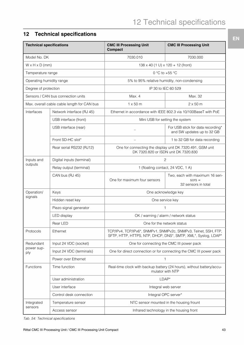
12 Technical specifications
EN
12 Technical specificationsTab. 54: Technical specifications
Technical specifications CMC III Processing Unit Compact
CMC III Processing Unit
Model No. DK 7030.010 7030.000
W x H x D (mm) 138 x 40 (1 U) x 120 + 12 (front)
Temperature range 0 °C to +55 °C
Operating humidity range 5% to 95% relative humidity, non-condensing
Degree of protection IP 30 to IEC 60 529
Sensors / CAN bus connection units Max. 4 Max. 32
Max. overall cable cable length for CAN bus 1 x 50 m 2 x 50 m
Interfaces Network interface (RJ 45) Ethernet in accordance with IEEE 802.3 via 10/100BaseT with PoE
USB interface (front) Mini USB for setting the system
USB interface (rear) – For USB stick for data recording* and SW updates up to 32 GB
Front SD-HC slot* – 1 to 32 GB for data recording
Rear serial RS232 (RJ12) One for connecting the display unit DK 7320.491, GSM unit DK 7320.820 or ISDN unit DK 7320.830
Inputs and outputs
Digital inputs (terminal) 2
Relay output (terminal) 1 (floating contact, 24 VDC, 1 A)
CAN bus (RJ 45)One for maximum four sensors
Two, each with maximum 16 sen-sors =
32 sensors in total
Operation/signals
Keys One acknowledge key
Hidden reset key One service key
Piezo signal generator 1
LED display OK / warning / alarm / network status
Rear LED One for the network status
Protocols Ethernet TCP/IPv4, TCP/IPv6*, SNMPv1, SNMPv2c, SNMPv3, Telnet, SSH, FTP, SFTP, HTTP, HTTPS, NTP, DHCP, DNS*, SMTP, XML*, Syslog, LDAP*
Redundant power sup-ply
Input 24 VDC (socket) One for connecting the CMC III power pack
Input 24 VDC (terminals) One for direct connection or for connecting the CMC III power pack
Power over Ethernet 1
Functions Time function Real-time clock with backup battery (24 hours), without battery/accu-mulator with NTP
User administration LDAP*
User interface Integral web server
Control desk connection Integral OPC server*
Integrated sensors
Temperature sensor NTC sensor mounted in the housing frount
Access sensor Infrared technology in the housing front
Rittal CMC III Processing Unit / CMC III Processing Unit Compact 43

12 Technical specifications
EN
Note:All functions in the table marked with an "*" will be available as software update. This software update can be downloaded from the Internet page specified in chapter 15 "Customer service addresses".44 Rittal CMC III Processing Unit / CMC III Processing Unit Compact

Rittal CMC III Processing Unit / CMC III Processing Unit Compact 45
13 Accessories
EN13 AccessoriesIn addition to the integrated sensors, the CAN bus in-terface allows a wide range of sensors, actuators and systems for access monitoring to be connected. A de-tailed listing of the complete range of accessories can be found at the Internet address specified in chapter 15 "Customer service addresses".
14 Glossary
EN
46 Rittal CMC III Processing Unit / CMC III Processing Unit Compact
14 GlossaryCMC III PU (CMC III Processing Unit):
The CMC III PU is the core product of the Rittal en-closure monitoring and control system for the elec-tronic monitoring of enclosures and server racks.
GSM card:Telephone card for a mobile telephone.
Hysteresis:If an upper limit value is overshot (SetPtHigh) or a lower limit value is undershot (SetPtLow) a warning or an alarm will be output immediately. For a hyster-esis of x%, the warning or alarm for undershooting an upper limit value or overshooting a lower limit val-ue clears only for a difference of x/100*limit value to the limit value.
MIB (Management Information Base):The MIB was developed to fetch and change net-work elements. The MIB for SNMP was defined in the RFC 1157; the MIB-II for TCP/IP was defined in the RFC 1213. The MIBs have been registered as the OID for the IANA (Internet Assigned Numbers Au-thority). Once an object has been assigned to an OID, the meaning may no longer be changed. An overlapping with other OIDs is not permitted.
SMS service number:The telephone number that the telephone provider makes available for sending SMS messages.
SNMP (Simple Network Management Protocol):The SNMP is a simple network management proto-col based on TCP/IP. It was developed to allow net-work components to be monitored and controlled at a central management station.
Telnet:Telnet is a protocol to allow guest access to a remote server. The Telnet program provides the required client functions of the protocol.
Trap:Trap is the unrequested sending of SNMP messag-es.
Trap receiver:The trap receiver is the recipient of SNMP messag-es.

Rittal CMC III Processing Unit / CMC III Processing Unit Compact 47
15 Customer service addresses
EN15 Customer service addressesFor technical questions, please contact:Tel.: +49 (0)2772/505-9052E-mail: [email protected]: www.rittal.de
For complaints or service requests, please contact:Tel.: +49 (0)2772/505-1855E-mail: [email protected]

1. A
ufl.
06.2
011
/ Id.
-Nr.
XXX
XXX
EnclosuresPower DistributionClimate ControlIT InfrastructureSoftware & Services
RITTAL GmbH & Co. KG Postfach 1662 D-35726 HerbornPhone +49(0)2772 505-0 Fax +49(0)2772 505-2319 E-mail: [email protected] www.rittal.com