Embed Size (px)
Citation preview

CMOS-320CMOS-220UNIVERSAL MULTI-VIEW CAMERA/ UNIVERSAL REAR VIEW CAMERAINSTRUCTION MANUALCAMÉRA MULTI-VUES UNIVERSELLE/ CAMÉRA DE RECUL UNIVERSELLEMODE D’EMPLOIUNIVERSAL MULTIVIEW-KAMERA/ UNIVERSAL RÜCKFAHRKAMERABEDIENUNGSANLEITUNGUNIVERSELE MULTIVIEWCAMERA/ UNIVERSELE ACHTERUITRIJCAMERAGEBRUIKSAANWIJZING
LYT2720-001A (W)© 2014 JVC KENWOOD Corporation
Take the time to read through this instruction manual.Familiarity with installation and operation procedures will help you obtain the best performance from your new Universal Camera.
For your recordsRecord the serial number, found on the back of the unit, in the spaces designated on the warranty card, and in the space provided below. Refer to the model and serial numbers whenever you call upon your Kenwood dealer for information or service on the product.Model CMOS-320/CMOS-220 Serial number
US Residence Only
Register OnlineRegister your Kenwood product at www.Kenwoodusa.com
LVT2720-001A.indb 1 14/02/14 15:09
2 | CMOS-320/CMOS-220
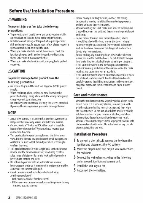
• Beforefinallyinstallingtheunit,connectthewiringtemporarily,makingsureitisallconnectedupproperly,andtheunitandthesystemwork.
• Whenmountingthisunit,makesurenoneoftheleadsaretrappedbetweenthisunitandthesurroundingmetalworkorfittings.
• Donotmountthisunitneartheheateroutlet,whereitwouldbeaffectedbyheat,ornearthedoors,whererainwatermightsplashontoit.(Neverinstallinlocationssuchastheabovebecauseofthedangerofmalfunctionduetohightemperatures.)
• Beforedrillinganymountingholesalwayscheckbehindwhereyouwanttodrilltheholes.Donotdrillintothegasline,brakeline,electricalwiringorotherimportantparts.
• Ifthisunitisinstalledinthepassengercompartment,anchoritsecurelysoitdoesnotbreakfreewhilethecarismoving,andcauseinjuryoranaccident.
• Ifthisunitisinstalledunderafrontseat,makesureitdoesnotobstructseatmovement.Routeallleadsandcordscarefullyaroundtheslidingmechanismsotheydonotgetcaughtorpinchedinthemechanismandcauseashortcircuit.
Care and maintenance• Whentheproductgetsdirty,wipedrywithasiliconcloth
orsoftcloth.Ifitisseriouslystained,removestainwithaclothmoistenedwithaneutralcleanerandthenwipethecleaneraway.Donotuseahardclothand/oravolatilesubstancesuchaslacquerthinneroralcohol,scratches,deformation,degradationand/ordamagemayresult.
• Whenalenscomponentgetsdirty,wipegentlywithasoftclothmoistenedwithwater.Donotrubwithadryclothtopreventscratchingthelens.
Installation Procedure1 Topreventashortcircuit,removethekeyfromthe
ignitionanddisconnectthe-battery.2 Maketheproperinputandoutputwireconnections
foreachunit.3 Connectthewiringharnesswiresinthefollowing
order:ground,ignitionandcameraunit.4 Installtheunitinyourcar.5 Reconnectthe-battery.
WARNING
To prevent injury or fire, take the following precautions:• Topreventashortcircuit,neverputorleaveanymetallic
objects(suchascoinsormetaltools)insidetheunit.• Installationandwiringofthisproductrequirespecialist
skillandexperience.Toassureyoursafety,pleaserequestaspecialisttechniciantoinstalltheunit.
• Whenyoumakeaholetoinstallthecamera,checkthelocationofpipes,tanksandwiringandavoidtouchingthem.Otherwiseitmaycausethefire.
• Whenyoumakeaholewithadrill,usegogglestoprotectyoureyes.
CAUTION
To prevent damage to the product, take the following precautions:• Makesuretogroundtheunittoanegative12VDCpower
supply.• Whenreplacingafuse,onlyuseanewfusewiththe
prescribedrating.Usingafusewiththewrongratingmaycauseyourunittomalfunction.
• Donotuseyourownscrews.Useonlythescrewsprovided.Ifyouusethewrongscrews,youcoulddamagetheunit.
NOTE• Arearviewcameraisacamerathatprovidessymmetrical
imagesinthesamewayasrearandsideviewmirrors.• ConnectiontoaTVwithanRCAvideoinputispossible,
butconfirmwhethertheTVyouusehasareversegearconnectionfunction.
• Thisproductisdesignedtosupplementthedriver’srearview,butthecameraimagesdonotshowalldangersandobstacles.Besuretolookbehindyouwhenreversingtoconfirmtheview.
• Thisproductfeaturesawide-anglelens,sothenearviewiswideandthefarviewisnarrow,whichmaycreateafalsesenseofdistance.Besuretolookbehindyouwhenreversingtoconfirmtheview.
• Donotwashyourcarwithanautomaticcarwashorhigh-pressurewaterasitmayresultinwaterenteringthecameraorthecamerafallingoff.
• Checkcamerabracketinstallationbeforedriving. Arethescrewsloose?
-Isthecamerabracketfirmlysecured?-Iftherearviewcameracomesloosewhileyouaredriving
itmaycauseanaccident.
Before Use/ Installation Procedure
LVT2720-001A.indb 2 14/02/14 15:09
CMOS-320/CMOS-220 | 3
ENGL
ISH
• Laythecordsbyavoidinghigh-temperatureareas.Usecorrugatedtubesforwiringinsidetheengineroom.Ifacordcontactsahigh-temperatureareaofthevehicle,thecoatingmaymeltandcauseshort-circuiting,whichmayleadtoafireorelectricshockhazard.
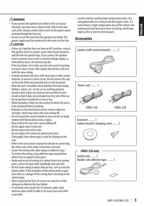
Accessories
Before Use/ Installation Procedure
WARNING• Ifyouconnecttheignitionwire(Red)tothecarchassis
(Ground),youmaycauseashortcircuit,thatinturnmaystartafire.Alwaysconnectthosewirestothepowersourcerunningthroughthefusebox.
• Donotcutoutthefusefromtheignitionwire(Red).Thepowersupplymustbeconnectedtothewiresviathefuse.
CAUTION• Ifyourcar’signitiondoesnothaveanACCposition,connect
theignitionwirestoapowersourcethatcanbeturnedonandoffwiththeignitionkey.Ifyouconnecttheignitionwiretoapowersourcewithaconstantvoltagesupply,aswithbatterywires,thebatterymaydie.
• Ifthefuseblows,firstmakesurethewiresaren’ttouchingtocauseashortcircuit,thenreplacetheoldfusewithonewiththesamerating.
• Insulateunconnectedwireswithvinyltapeorothersimilarmaterial.Topreventashortcircuit,donotremovethecapsontheendsoftheunconnectedwiresortheterminals.
• Aftertheunitisinstalled,checkwhetherthebrakelamps,blinkers,wipers,etc.onthecarareworkingproperly.
• Installsothatitdoesnotobstructtherearfieldofview.• Installsothatitdoesnotprotrudefromthesideofthecar.• Donotperforminstallationinrainorfog.• Whenhumidityishigh,drythesurfacetowhichtheunitis
tobeattachedbeforeinstalling.• Moistureontheattachmentsurfacereducesadhesive
strength,whichmayleadtotheunitcomingoff.• Donotattachthecamerabrackettoareasonthecarbody
treatedwithfluorocarbonresin,orglass.• Mayresultintherearviewcamerafallingoff.- Donotapplywatertotheunit.- Donotexposetheunittorain.- Donotsubjectthecameratounnecessaryforce.- Thoroughlycleanwheretapeisusedforstickingonthe
unit.• RefertotheInstruction’smanualfordetailsonconnecting
theotherunits,thenmakeconnectionscorrectly.• Securethewiringwithcableclampsoradhesivetape.
Toprotectthewiring,wrapadhesivetapearoundthemwheretheylieagainstmetalparts.
• Routeandsecureallwiringsoitcannottouchanymovingparts,suchasthegearshift,handbrakeandseatrails.
• Donotroutewiringinplacesthatgethot,suchasneartheheateroutlet.Iftheinsulationofthewiringmeltsorgetstorn,thereisadangerofthewiringshort-circuitingtothevehiclebody.
• Whenreplacingthefuse,besuretouseonlyfuseoftheratingprescribedonthefuseholder.
• TominimizenoiselocatetheTVantennacable,radioantennacableandRCAcableasfarawayfromeachotheraspossible.
Grommet..........1Camerabracketclampingscrew..........1
Camera(withcamerabracket)..........1
Switchunit..........1Double-sideadhesivetape..........1
CMOS-320 only
Powercord..........1
CMOS-320 CMOS-220
LVT2720-001A.indb 3 14/02/14 15:09
4 | CMOS-320/CMOS-220
CAUTION•Theadjustmentsduringcamerasettingmaybehindereddependingonthecamerainstallationposition.Donotinstallthecamerasecurelybutattachitonlytemporarilyuntilthecamerasettinghascompleted.
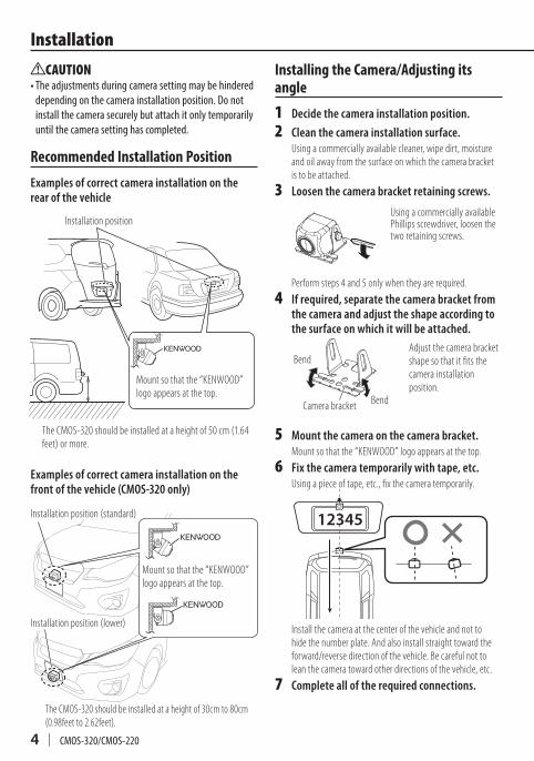
Recommended Installation Position
Examples of correct camera installation on the rear of the vehicle
Installation position
The CMOS-320 should be installed at a height of 50 cm (1.64 feet) or more.
Mount so that the “KENWOOD” logo appears at the top.
Examples of correct camera installation on the front of the vehicle (CMOS-320 only)
The CMOS-320 should be installed at a height of 30cm to 80cm (0.98feet to 2.62feet).
Mount so that the “KENWOOD” logo appears at the top.
Installation position (standard)
Installation position (lower)
Installing the Camera/Adjusting its angle
1 Decide the camera installation position.
2 Clean the camera installation surface.Using a commercially available cleaner, wipe dirt, moisture and oil away from the surface on which the camera bracket is to be attached.
3 Loosen the camera bracket retaining screws.
Using a commercially available Phillips screwdriver, loosen the two retaining screws.
Perform steps 4 and 5 only when they are required.
4 If required, separate the camera bracket from the camera and adjust the shape according to the surface on which it will be attached.
Bend
Bend
Camera bracket
Adjust the camera bracket shape so that it fits the camera installation position.
5 Mount the camera on the camera bracket.Mount so that the “KENWOOD” logo appears at the top.
6 Fix the camera temporarily with tape, etc.Using a piece of tape, etc., fix the camera temporarily.
12345
Install the camera at the center of the vehicle and not to hide the number plate. And also install straight toward the forward/reverse direction of the vehicle. Be careful not to lean the camera toward other directions of the vehicle, etc.
7 Complete all of the required connections.
Installation
LVT2720-001A.indb 4 14/02/14 15:10
CMOS-320/CMOS-220 | 5
ENGL
ISH
Installing the Camera/Adjusting its angle
1 Decide the camera installation position.
2 Clean the camera installation surface.Using a commercially available cleaner, wipe dirt, moisture and oil away from the surface on which the camera bracket is to be attached.
3 Loosen the camera bracket retaining screws.
Using a commercially available Phillips screwdriver, loosen the two retaining screws.
Perform steps 4 and 5 only when they are required.
4 If required, separate the camera bracket from the camera and adjust the shape according to the surface on which it will be attached.
Bend
Bend
Camera bracket
Adjust the camera bracket shape so that it fits the camera installation position.
5 Mount the camera on the camera bracket.Mount so that the “KENWOOD” logo appears at the top.
6 Fix the camera temporarily with tape, etc.Using a piece of tape, etc., fix the camera temporarily.
12345
Install the camera at the center of the vehicle and not to hide the number plate. And also install straight toward the forward/reverse direction of the vehicle. Be careful not to lean the camera toward other directions of the vehicle, etc.
7 Complete all of the required connections.
8 Display the camera video.Before viewing the camera, apply the parking brake and chock the wheels so that the vehicle will not move. Otherwise, an unexpected accident may result.For displaying the camera video, read the instruction manual for your video monitor.
When the camera is installed as a rearview camera: Change the shift lever to the R (Reverse) range to view the image of the rear of the vehicle.
When the camera is installed as a front camera (CMOS-320 only): Refer to the instruction manual of the unit that you have connected this camera to, and display the image of the front of the vehicle.
9 Adjust the camera angle.When adjusting the camera angle, be careful not to stretch the camera cord.
When installing CMOS-220 as a rearview camera: Adjust the angle so that the rear of the vehicle or the bumper can be seen at the bottom of the monitor.
Vehicle rear part or bumper
When installing CMOS-320 as a rearview camera: Refer to “Display View Switching” (page 14) and switch the image to [Overhead View]. Adjust the camera angle so that the guideline and the parking lines become vertical.
Guideline
Installation When installing CMOS-320 as a front camera:
Before adjusting the camera angle, perform “Camera ID Setting” (page 13) and “Camera Setting Procedure” (page 10).
When you select [Standard] for “Mounting Position Setting”, switch the image to [Overhead View] (page 14) and adjust the camera angle so that the guideline and the parking lines become vertical.
When you select [Lower] for “Mounting Position Setting”, switch the image to [Corner View] (page 14) and then adjust the angle of the camera to straighten the ground lines in the left and right screens.
10 Set the camera.
When using CMOS-320 as a rearview camera: Refer to page 9 to 13 and perform “Preparation Before Camera Setting”, “Overhead View Image Adjustment” and “Wide View Guideline Adjustment”.
When using CMOS-320 as a front camera: When you select [Standard] for “Mounting Position Setting”, refer to page 9 to 13 and perform “Preparation Before Camera Setting”, “Overhead View Image Adjustment” and “Wide View Guideline Adjustment”.
When you select [Lower] for “Mounting Position Setting”, refer to page 9 to 13 and perform “Preparation Before Camera Setting” and “Overhead View Image Adjustment”. You cannot perform “Wide View Guideline Adjustment”.
11 After adjusting the camera angle, tighten the retaining screws firmly.Inspect the retaining screws at times. If they are loose, tighten them firmly.
Next page 3
LVT2720-001A.indb 5 14/02/14 15:10
6 | CMOS-320/CMOS-220
Enginekey
Camera
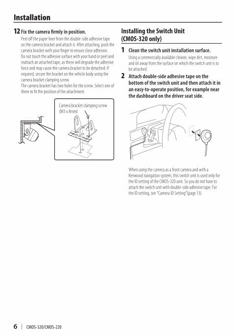
12 Fix the camera firmly in position.Peel off the paper liner from the double-side adhesive tape on the camera bracket and attach it. After attaching, push the camera bracket with your finger to ensure close adhesion.Do not touch the adhesive surface with your hand or peel and reattach an attached tape, as these will degrade the adhesive force and may cause the camera bracket to be detached. If required, secure the bracket on the vehicle body using the camera bracket clamping screw.The camera bracket has two holes for the screw. Select one of them to fit the position of the attachment.
Camera bracket clamping screw(M3 x 8mm)
Installing the Switch Unit (CMOS-320 only)
1 Clean the switch unit installation surface.Using a commercially available cleaner, wipe dirt, moisture and oil away from the surface on which the switch unit is to be attached.
2 Attach double-side adhesive tape on the bottom of the switch unit and then attach it in an easy-to-operate position, for example near the dashboard on the driver seat side.
When using the camera as a front camera and with a Kenwood navigation system, this switch unit is used only for the ID setting of the CMOS-320 unit. So you do not have to attach the switch unit with double-side adhesive tape. For the ID setting, see “Camera ID Setting”(page 13)
Installation
LVT2720-001A.indb 6 14/02/14 15:10
CMOS-320/CMOS-220 | 7
ENGL
ISH
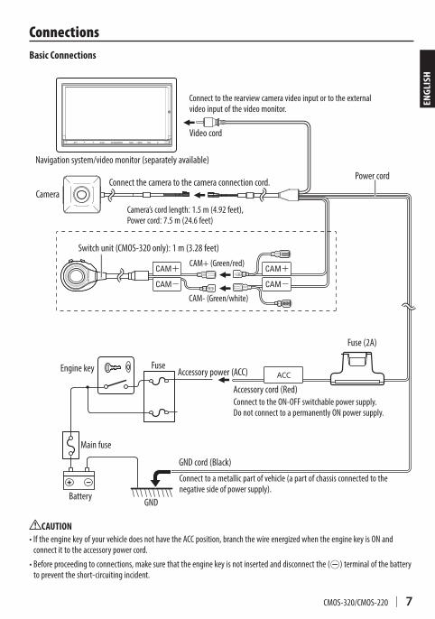
Videocord
Navigationsystem/videomonitor(separatelyavailable)
GNDcord(Black)
Accessorycord(Red)
GNDBattery
Mainfuse
FuseEnginekey
Connecttoametallicpartofvehicle(apartofchassisconnectedtothenegativesideofpowersupply).
CAUTION•IftheenginekeyofyourvehicledoesnothavetheACCposition,branchthewireenergizedwhentheenginekeyisONandconnectittotheaccessorypowercord.
•Beforeproceedingtoconnections,makesurethattheenginekeyisnotinsertedanddisconnectthe(-)terminalofthebatterytopreventtheshort-circuitingincident.
ConnecttotheON-OFFswitchablepowersupply.DonotconnecttoapermanentlyONpowersupply.
Fuse(2A)
CameraConnectthecameratothecameraconnectioncord.
Connecttotherearviewcameravideoinputortotheexternalvideoinputofthevideomonitor.
Powercord
Accessorypower(ACC)
Switchunit(CMOS-320only):1m(3.28feet)
Basic Connections
Camera’scordlength:1.5m(4.92feet),Powercord:7.5m(24.6feet)
Connections
CAM+(Green/red)
CAM-(Green/white)
LVT2720-001A.indb 7 14/02/14 15:10
8 | CMOS-320/CMOS-220
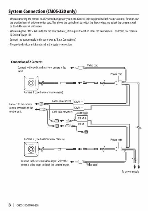
Videocord
Videocord
Camera1(Usedasrearviewcamera)
Camera2(Usedasfrontviewcamera)
Connecttothededicatedrearviewcameravideoinput.
Connecttotheexternalvideoinput.Selecttheexternalvideoinputtocheckthecameraimage.
Connecttothecameracontrolterminalsofthecontrolunit.
CAM+(Green/red)
CAM-(Green/white)
Connection of 2 Cameras
Powercord
System Connection (CMOS-320 only)
Powercord
Topowersupply
•WhenconnectingthecameratoaKenwoodnavigationsystemetc,(Controlunit)equippedwiththecameracontrolfunction,usetheprovidedcontrolunitconnectioncord.Thisallowsthecontrolunittoswitchthedisplayviewandadjustthecameraaswellontouchthecontrolunitscreen.
•WhenusingtwoCMOS-320units(forthefrontandrear),itisrequiredtosetanIDforthefrontcamera.Fordetails,see“CameraIDSetting”(page13).
•Connectthepowersupplyinthesamewayas“BasicConnections”.•Theprovidedswitchunitisnotusedinthesystemconnection.
LVT2720-001A.indb 8 14/02/14 15:10
CMOS-320/CMOS-220 | 9
ENGL
ISH
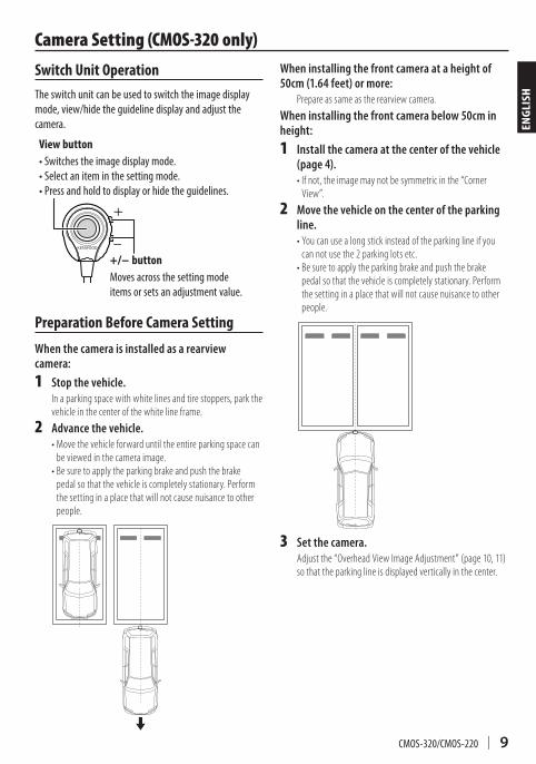
Switch Unit OperationTheswitchunitcanbeusedtoswitchtheimagedisplaymode,view/hidetheguidelinedisplayandadjustthecamera.
View button•Switchestheimagedisplaymode.•Selectaniteminthesettingmode.•Pressandholdtodisplayorhidetheguidelines.
+/− buttonMovesacrossthesettingmodeitemsorsetsanadjustmentvalue.
Preparation Before Camera Setting
When the camera is installed as a rearview camera:
1 Stop the vehicle.In a parking space with white lines and tire stoppers, park the vehicle in the center of the white line frame.
2 Advance the vehicle.• Move the vehicle forward until the entire parking space can
be viewed in the camera image.• Be sure to apply the parking brake and push the brake
pedal so that the vehicle is completely stationary. Perform the setting in a place that will not cause nuisance to other people.
When installing the front camera at a height of 50cm (1.64 feet) or more:
Prepare as same as the rearview camera.
When installing the front camera below 50cm in height:
1 Install the camera at the center of the vehicle (page 4).• If not, the image may not be symmetric in the “Corner
View”.
2 Move the vehicle on the center of the parking line.• You can use a long stick instead of the parking line if you
can not use the 2 parking lots etc.• Be sure to apply the parking brake and push the brake
pedal so that the vehicle is completely stationary. Perform the setting in a place that will not cause nuisance to other people.
3 Set the camera.Adjust the “Overhead View Image Adjustment” (page 10, 11) so that the parking line is displayed vertically in the center.
Camera Setting (CMOS-320 only)
LVT2720-001A.indb 9 14/02/14 15:10
10 | CMOS-320/CMOS-220
Camera Setting Procedure
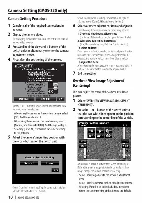
1 Complete all of the required connections in advance.
2 Display the camera video.For displaying the camera video, read the instruction manual for your video monitor.
3 Press and hold the view and + buttons of the switch unit simultaneously to enter the camera adjustment mode.
4 First select the positioning of the camera.
Use the + or – button to select an item and press the view button to enter the selection.•Whenusingthecameraastherearviewcamera,select[OK].Andthengotostep6.
•Whenusingthecameraasthefrontcamera,select[Normal]andthenselect[OK].Andthengotostep5.
• Selecting[ResetAll]resetsallofthecamerasettingstothedefaults.
5 Adjust the camera’s mounting position with the + or – buttons on the switch unit.
Select [Standard] when installing the camera at a height of 50cm to 80cm (1.64feet to 2.62feet).
Select [Lower] when installing the camera at a height of 30cm to below 50cm (0.98feet to below 1.64feet).
6 Select a camera adjustment item and adjust it.The following items are available for camera adjustment.1. Overhead view image adjustments
(Centering, Right-and-Left angle, Up-and-Down Angle)2. Wide view guideline adjustments
(Size, Horizontal direction, Red Line Position Setting)To select an item:Press the + or – button to select an item and press the view button to enter the selection. When an adjustment item is selected, the frame of its icon turns from blue to yellow.To adjust the item:After selecting the item, press the + or – button to adjust it and press the view button to enter the adjusted value.
7 End the setting.
Overhead View Image Adjustment (Centering)Thisitemadjuststhecenterofthecamerainstallationposition.
1 Select “OVERHEAD VIEW IMAGE ADJUSTMENT (CENTERING)”.
2 Press the + or – button of the switch unit so that the two white lines appear on the position corresponding to the center line of the vehicle.
Adjustment is possible by two steps to the left and right. If the adjustment is not possible in the currently available range, change the camera position before retry.• Select[Back]togobacktothepreviousadjustmentitem.
• Select[Next]toadvancetothenextadjustmentitem.• Selecting[Reset]inanindividualadjustmentitemresetsthecamerasettingofthatitemtothedefault.
Camera Setting (CMOS-320 only)
LVT2720-001A.indb 10 14/02/14 15:10
CMOS-320/CMOS-220 | 11
ENGL
ISH
• Select[ ]toinverttheiconupsidedown.3 After completing the adjustment, press the
view button.
Advances to “OVERHEAD VIEW IMAGE ADJUSTMENT (Right-and-Left ANGLE)”.
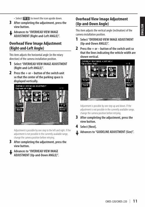
Overhead View Image Adjustment (Right-and-Left Angle)Thisitemadjuststhehorizontalangle(intherotarydirection)ofthecamerainstallationposition.
1 Select “OVERHEAD VIEW IMAGE ADJUSTMENT (Right-and-Left ANGLE)”.
2 Press the + or – button of the switch unit so that the center of the parking space is displayed vertically.
Adjustment is possible by one step to the left and right. If the adjustment is not possible in the currently available range, change the camera position before retrying.
3 After completing the adjustment, press the view button.
Advances to “OVERHEAD VIEW IMAGE ADJUSTMENT (Up-and-Down ANGLE)”.
Overhead View Image Adjustment (Up-and-Down Angle)Thisitemadjuststheverticalangle(inclination)ofthecamerainstallationposition.
1 Select “OVERHEAD VIEW IMAGE ADJUSTMENT (Up-and-Down ANGLE)”.
2 Press the + or – button of the switch unit so that the lines indicating the vehicle width are shown vertical.
Adjustment is possible by one step up and down. If the adjustment is not possible in the currently available range, change the camera position before retrying.
3 After completing the adjustment, press the view button.
4 Select [Next].
Advances to “GUIDELINE ADJUSTMENT (Size)”.
Camera Setting (CMOS-320 only)
LVT2720-001A.indb 11 14/02/14 15:10
12 | CMOS-320/CMOS-220
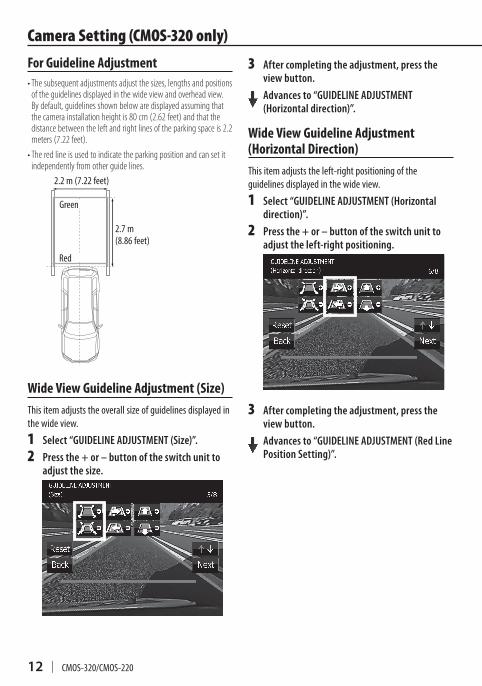
For Guideline Adjustment• The subsequent adjustments adjust the sizes, lengths and positions
of the guidelines displayed in the wide view and overhead view. By default, guidelines shown below are displayed assuming that the camera installation height is 80 cm (2.62 feet) and that the distance between the left and right lines of the parking space is 2.2 meters (7.22 feet).
• The red line is used to indicate the parking position and can set it independently from other guide lines.
Green
Red
2.7m(8.86feet)
2.2m(7.22feet)
Wide View Guideline Adjustment (Size)Thisitemadjuststheoverallsizeofguidelinesdisplayedinthewideview.
1 Select “GUIDELINE ADJUSTMENT (Size)”.
2 Press the + or – button of the switch unit to adjust the size.
3 After completing the adjustment, press the view button.
Advances to “GUIDELINE ADJUSTMENT (Horizontal direction)”.
Wide View Guideline Adjustment (Horizontal Direction)Thisitemadjuststheleft-rightpositioningoftheguidelinesdisplayedinthewideview.
1 Select “GUIDELINE ADJUSTMENT (Horizontal direction)”.
2 Press the + or – button of the switch unit to adjust the left-right positioning.
3 After completing the adjustment, press the view button.
Advances to “GUIDELINE ADJUSTMENT (Red Line Position Setting)”.
Camera Setting (CMOS-320 only)
LVT2720-001A.indb 12 14/02/14 15:10
CMOS-320/CMOS-220 | 13
ENGL
ISH
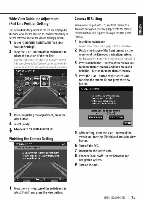
Wide View Guideline Adjustment (Red Line Position Setting)Thisitemadjuststhepositionoftheredlinedisplayedinthewideview.Theredlinecanbeusedindependentlytosetthereferencelineforthevehicleparkingposition.
1 Select “GUIDELINE ADJUSTMENT (Red Line Position Setting)”.
2 Press the + or – button of the switch unit to adjust the position of the red line.Move the red line until the edge of your vehicle’s bumper. If the edge of your vehicle’s bumper cannot be seen in the monitor, move the red line around the edge of your vehicle.
3 After completing the adjustment, press the view button.
4 Select [Next].
Advances to “SETTING COMPLETE”.
Finishing the Camera Setting
1 Press the + or – button of the switch unit to select [Finish] and press the view button.
Camera Setting (CMOS-320 only)
Camera ID SettingWhenconnectingaCMOS-320asafrontcameratoaKenwoodnavigationsystemequippedwiththecameracontrolfunction,itisrequiredtoassigntheIDto[FrontCamera].
1 Install the switch unit.Refer to “Basic Connections” (page 7) for the connection.
2 Display the image of the front camera on the monitor of the Kenwood navigation system.For displaying the image, refer to the instruction manual of it.
3 Press and hold the + button of the switch unit for more than 2 seconds, and then press and hold the – button for more than 2 seconds.
4 Press the + or – button of the switch unit to select the camera ID, and press the view button.
5 After setting, press the + or – button of the switch unit to select [Finish] and press the view button.
6 Turn off the ACC.
7 Disconnect the switch unit.
8 Connect CAM+/CAM– to the Kenwood car navigation system.
9 Turn on the ACC.
LVT2720-001A.indb 13 14/02/14 15:10
14 | CMOS-320/CMOS-220
Display View Switching (CMOS-320 only)
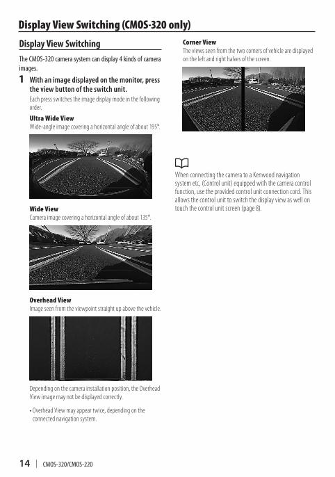
Display View SwitchingTheCMOS-320camerasystemcandisplay4kindsofcameraimages.
1 With an image displayed on the monitor, press the view button of the switch unit.Each press switches the image display mode in the following order.
Ultra Wide ViewWide-angle image covering a horizontal angle of about 195°.
Wide ViewCamera image covering a horizontal angle of about 135°.
Overhead ViewImage seen from the viewpoint straight up above the vehicle.
Depending on the camera installation position, the Overhead View image may not be displayed correctly.
• Overhead View may appear twice, depending on the connected navigation system.
Corner ViewThe views seen from the two corners of vehicle are displayed on the left and right halves of the screen.
When connecting the camera to a Kenwood navigation system etc, (Control unit) equipped with the camera control function, use the provided control unit connection cord. This allows the control unit to switch the display view as well on touch the control unit screen (page 8).
LVT2720-001A.indb 14 14/02/14 15:10
CMOS-320/CMOS-220 | 15
ENGL
ISH
Camnit (CMOS-320)Outputvideo
: Wide-angle mirror image (for rearview)/wide-angle normal image (for front view)
Sensor:1/3.6-inch color CMOS sensorNumberofpixels: Approx. 330,000 pixelsLens
: Wide angle, Focal length f=1.05 mm, F value 2.0Anglesofview
: Horizontal: Approx. 195° : Vertical: Approx. 145°
Videooutput: 1.0 Vp-p/ 75ΩIlluminationrange: Approx. 0.9 to 100,000 luxIrissystem: Electronic irisScanningsystem: InterlaceSynchronizingsystem: Internal synchronizationDimensions(WxHxD): 23.4 x 23.4 x 26.1 mmWeight: Approx. 23 g (without cable)
Camera Unit (CMOS-220)Outputvideo
: Wide-angle mirror image (for rearview)Sensor: 1/3.6-inch color CMOS sensorNumberofpixels: Approx. 330,000 pixelsLens
: Wide angle, Focal length f=1.12 mm, F value 2.2Anglesofview
: Horizontal: Approx. 128° : Vertical: Approx. 103°
Videooutput: 1.0 Vp-p/ 75ΩIlluminationrange: Approx. 0.9 to 100,000 luxIrissystem: Electronic irisScanningsystem: InterlaceSynchronizingsystem: Internal synchronizationDimensions(WxHxD): 23.4 x 23.4 x 23.9 mmWeight: Approx. 22 g (without cable)
Switch Unit (CMOS-320 only)Dimensions(WxHxD): 27.5 x 32.8 x 12 mmWeight: Approx. 10 g (without cable)
General
Operatingvoltage: 14.4V (9.0 V – 16.0 V)Max.currentconsumption(CMOS-320): 100 mAMax.currentconsumption(CMOS-220): 50 mA
•Mirrorimagemeansthatthevideoimageinvertstheleftandrightjustliketheimageseenontherearviewmirrororasidemirror.
•Specificationssubjecttochangewithoutnotice.
Information on Disposal of Old Electrical and Electronic Equipment and Batteries (applicable for countries that have adopted separate waste collection systems)
Productsandbatterieswiththesymbol(crossed-outwheeledbin)cannotbedisposedashouseholdwaste.Oldelectricalandelectronicequipmentandbatteriesshouldberecycledatafacilitycapableofhandlingtheseitemsandtheirwastebyproducts.Contactyourlocalauthorityfordetailsinlocatingarecyclefacilitynearesttoyou.Properrecyclingandwastedisposalwillhelpconserveresourceswhilstpreventingdetrimentaleffectsonourhealthandtheenvironment.Notice:Thesign“Pb”belowthesymbolfor
batteriesindicatesthatthisbatterycontainslead.
Specifications
LVT2720-001A.indb 15 14/02/14 15:10