Embed Size (px)
Citation preview
CMS PROFESSIOANL MANUAL
Page 1
CMS PROFESSIONAL user's manual
User's manual version 3.0 (January 2012)
This manual applies to program version CMS PROFFESIONAL 3.0.0.600
Page 2
Contents
1. Introduction .................................................................................................................................. 4
1.1 System description ............................................................................................................... 5
2. Using CMS software of the NET Proffesional System ........................................................ 6
2.1 Main view ............................................................................................................................... 7
2.2 Camera view ....................................................................................................................... 12
2.2 Establishing connection ................................................................................................... 14
2.3 Dynamic layout .................................................................................................................. 16
3. System tools ................................................................................................................................ 18
3.1 Address book ....................................................................................................................... 19
3.1 Connection list .................................................................................................................... 22
3.2 Archive browser .................................................................................................................. 23
3.2.1 Searching for motion in the archive recordings ................................................ 25
3.2.2 Export to .avi ................................................................................................................. 25
3.2.3 Backup copy ................................................................................................................ 26
3.3 Watch alarm inputs ........................................................................................................... 29
3.3 Photo browser ..................................................................................................................... 30
3.4 Server events ....................................................................................................................... 31
3.5 Dome control panel .......................................................................................................... 32
3.6 E-map .................................................................................................................................... 33
3.7 Synoptic table ..................................................................................................................... 34
4. Program settings ....................................................................................................................... 35
4.1 Camera and motion ......................................................................................................... 35
4.2 Disk archive .......................................................................................................................... 39
4.3 Dome control ...................................................................................................................... 43
4.3.1 Settings ........................................................................................................................... 43
4.4 Alarm inputs ......................................................................................................................... 45
4.5 Server events settings ........................................................................................................ 46
4.6 Program settings ................................................................................................................. 47
4.6.1 General .......................................................................................................................... 47
4.6.2 Photos ............................................................................................................................. 48
4.6.3 Settings ........................................................................................................................... 48
4.7 E-map editor ........................................................................................................................ 49
4.7 Output buttons .................................................................................................................... 53
4.9 Input buttons........................................................................................................................ 54

CMS PROFESSIOANL MANUAL
Page 3
4.10 Save settings ...................................................................................................................... 55
4.11 Help ...................................................................................................................................... 55
Page 4
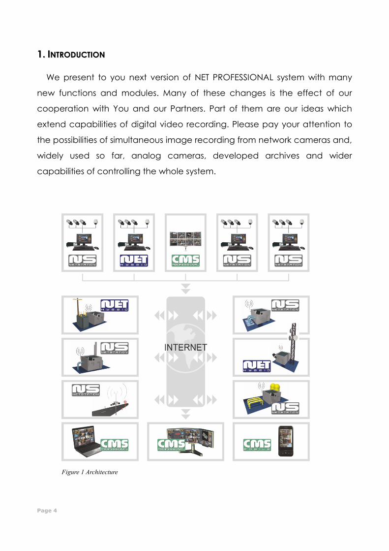
11.. IINNTTRROODDUUCCTTIIOONN
We present to you next version of NET PROFESSIONAL system with many
new functions and modules. Many of these changes is the effect of our
cooperation with You and our Partners. Part of them are our ideas which
extend capabilities of digital video recording. Please pay your attention to
the possibilities of simultaneous image recording from network cameras and,
widely used so far, analog cameras, developed archives and wider
capabilities of controlling the whole system.
Figure 1 Architecture
CMS PROFESSIOANL MANUAL
Page 5
11..11 SSYYSSTTEEMM DDEESSCCRRIIPPTTIIOONN
NET PROFESSIONAL is a digital video recorder designed for cooperation with CCTV
cameras. It uses PC class computers which work under control of Microsoft Windows VISTA
/ 7 32 Bit operating system. New NET PROFESSIONAL system version can record image from
up to 32 cameras, servicing 32 output switches and 32 alarm inputs. Moreover the system
can be hybrid that is one system can service both analog an IP cameras – thanks to this it
is possible to upgrade an existing installation and add IP or analog cameras. Managing
the video server through the network is possible. Program allows wide possibilities of motion
detection settings, searching the motion in archives, servicing alarm events. Differential
image-compression method guarantees image recording longer than in other systems of
that type without changing the image quality and storage space.
Software for managing NET PROFESSIONAL system consists of two independent
applications:
1. NET PROFESSIONAL (Video Digital Recording - Server)
2. CMS (Client Mobile Software – Client)
The first application is a server: processes image from the cameras, manages user
accounts, tasks, controls the cameras. The second one is used as a client. We can
connect to the server by a local network and do remote monitoring. Client application is
available on mobile device (mobile phones, Pocket PC, Tablets) which allows access to
camera images from any place in the world. Every installation of mobile application you
will find in this link http://mobi.alnetsystems.com/

Page 6
22.. UUSSIINNGG CCMMSS SSOOFFTTWWAARREE OOFF TTHHEE NNEETT PPRROOFFFFEESSIIOONNAALL SSYYSSTTEEMM
At the first run of the application, it is necessary to set up it's configuration
parameters.
It is done only once.
1. Choose language – application language selection
2. Time format – 12 / 24-hour time format selection
3. Date format – date format selection – dd – day, mm – month, yyyy – year
4. Monitor format – image display format – setting depends on your display
device (CRT / LCD) – 4x3 or 16x9
5. Store settings as – saves above settings into one of the profiles:
- DEFAULT
- GLOBAL SETTINGS
- CURRENT USER
Figure 2: Configuration of the program
parameters
CMS PROFESSIOANL MANUAL
Page 7
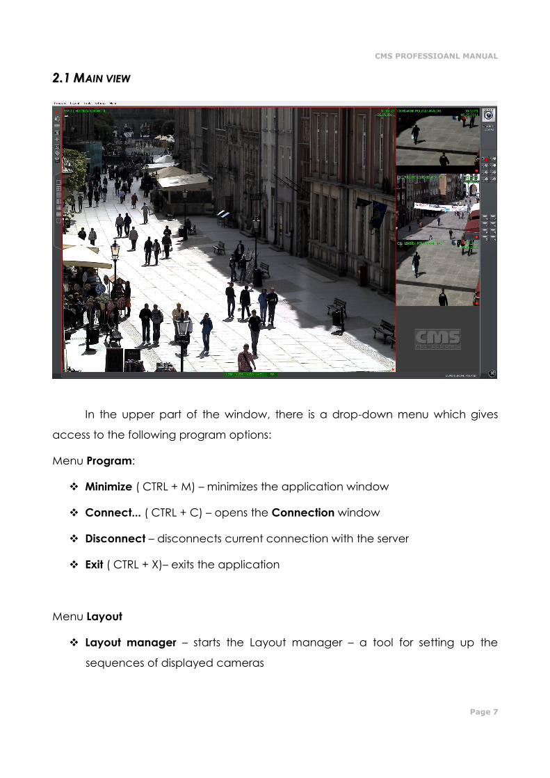
22..11 MMAAIINN VVIIEEWW
In the upper part of the window, there is a drop-down menu which gives
access to the following program options:
Menu Program:
Minimize ( CTRL + M) – minimizes the application window
Connect... ( CTRL + C) – opens the Connection window
Disconnect – disconnects current connection with the server
Exit ( CTRL + X)– exits the application
Menu Layout
Layout manager – starts the Layout manager – a tool for setting up the
sequences of displayed cameras
Page 8
Menu Tools
Address book – opens the Address book
Connection list – opens the window with the list of active connections
Remote archives – opens the remote archive of connected server
Local archives ( CTRL + A)– opens the client's local archive
Archives from path – opens the archive from selected path
Watch alarm inputs – input alarm list
Browse photos – opens the Photo Browser
Server events – list of the server events
Dome panel ( CTRL + D)– opens dome control panel
E-map – displays graphic camera layout of connected server
Volume control ( CTRL + V)– opens Windows volume control panel
Synoptic table – checks network activity of defined NET PROFESSIONAL
servers
Menu Settings
Camera and motion... – picture quality settings and motion detection
alarms settings
Archive storage – Archive storage settings for local recordings
Dome control – Dome control settings
Alarm inputs – alarm inputs notifications settings
Server events – server events settings
Program settings – application parameters settings
E-map editor – allows creating own graphic surveillance devices layout
CMS PROFESSIOANL MANUAL
Page 9
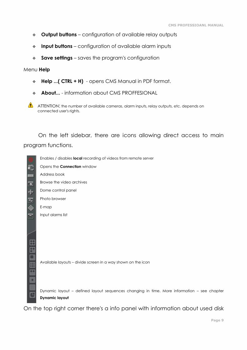
Output buttons – configuration of available relay outputs
Input buttons – configuration of available alarm inputs
Save settings – saves the program's configuration
Menu Help
Help ...( CTRL + H) - opens CMS Manual in PDF format.
About... - information about CMS PROFFESIONAL
ATTENTION: the number of available cameras, alarm inputs, relay outputs, etc. depends on
connected user's rights.
On the left sidebar, there are icons allowing direct access to main
program functions.
Enables / disables local recording of videos from remote server
Opens the Connection window
Address book
Browse the video archives
Dome control panel
Photo browser
E-map
Input alarms list
Available layouts – divide screen in a way shown on the icon
Dynamic layout – defined layout sequences changing in time. More information – see chapter
Dynamic layout
On the top right corner there's a info panel with information about used disk
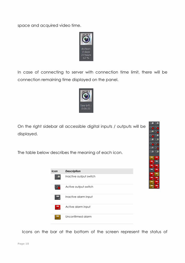
Page 10
space and acquired video time.
In case of connecting to server with connection time limit, there will be
connection remaining time displayed on the panel.
On the right sidebar all accessible digital inputs / outputs will be
displayed.
The table below describes the meaning of each icon.
Icon Description
Inactive output switch
Active output switch
Inactive alarm input
Active alarm input
Unconfirmed alarm
Icons on the bar at the bottom of the screen represent the status of
CMS PROFESSIOANL MANUAL
Page 11
available cameras and audio channels. Each icon consists of number of
camera/channel and it's name. Red rectangle, which appears beside the
number symbolizes motion detection on the camera or sound detection if it
appears beside audio channel number. If the icon is all red it means
channel failure – the signal is not transmitted.
Clicking with left mouse button on the icon will maximize the camera view
on full screen.
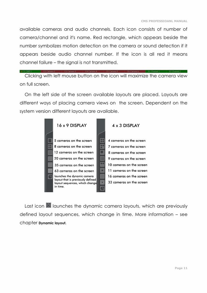
On the left side of the screen available layouts are placed. Layouts are
different ways of placing camera views on the screen. Dependent on the
system version different layouts are available.
Last icon launches the dynamic camera layouts, which are previously
defined layout sequences, which change in time. More information – see
chapter Dynamic layout.
Page 12
22..22 CCAAMMEERRAA VVIIEEWW
In the center of the screen the most important elements of the system are
placed. These elements are camera views. On each screen system can
display information such as: camera name, current time, number of
captured frames per second. Double clicking by left mouse button on the
camera view will bring this view full screen. Another double click will bring
back previous state of the view. When You put the cursor in the top right
corner of the camera view an additional menu will appear.
Icon Description
Enables / disables local recording of videos from remote server
Makes a snapshot
Selecting this option allows to enlarge the camera view. The example is presented below
When a camera works as a dome the icon starts the "mouse control" mode. To change
the position just click with left mouse button on the desired place in the camera view. To
zoom in and out, use the mouse scroll.
Zooming the image
While holding the left mouse button
pressed select the area to be zoomed. This
action does not affect the image size
stored in the archives. After releasing left
mouse button the image will be digitally
zoomed. This operation won't affect the
size of the image recorded in the
archives. This function may be useful
when cameras with optical zoom are
used. To go back to normal state select
the button.
CMS PROFESSIOANL MANUAL
Page 13
If you click with right mouse button on the camera view area during the
system work menu will appear. All available commands are described
below.
Name Description
Connect... Opens the Connection window
Set camera Displays the list of available cameras. Marked position means that the camera is
assigned to the particular area. To assign other camera choose it from the list
Sound channel List of sound channels assigned to the particular camera
Auto – assigns the channels to cameras as in the server configuration
Output switch Activates selected output switch
Display mode Normal - displays whole application window with tool bars.
Fullscreen - displays only camera image on fullscreen.
Preview – displays application window at the size controlled by user. Changing the
size is done by resizing window (catching it's corner with left mouse button).
Stay on top – in a preview mode application window will stay on top (that is it won't
be covered by other active programs).
Show menu – shows/hides menu bar at the top.
Hide buttons – hides the bottom bar with camera symbols.
Small buttons – small camera icons at the bottom bar
Large buttons - large camera icons at the bottom bar
Show tool buttons – shows/hides the bottom toolbar
Layout Switches to selected camera layout. Enables dynamic mode. Dynamic – if Camera
pop-up after alarm option was selected in camera configuration,it is possible to
temporarily disable/enable this option by marking it
Snapshot Makes screenshot (photo)
Disconnect Disconnects current connection with the server
Exit Exits the application
Most of the options mentioned above refer to single camera. It is very
important to choose the proper camera (by clicking with left mouse button
on it's display area) before selecting any option. Selected camera has a red
border.
Page 14
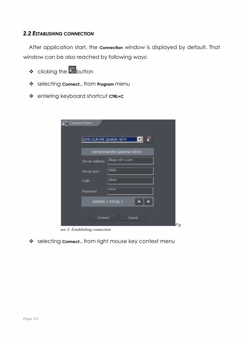
22..22 EESSTTAABBLLIISSHHIINNGG CCOONNNNEECCTTIIOONN
After application start, the Connection window is displayed by default. That
window can be also reached by following ways:
clicking the button
selecting Connect... from Program menu
entering keyboard shortcut CTRL+C
selecting Connect... from right mouse key context menu
Fig
ure 3: Establishing connection
CMS PROFESSIOANL MANUAL
Page 15
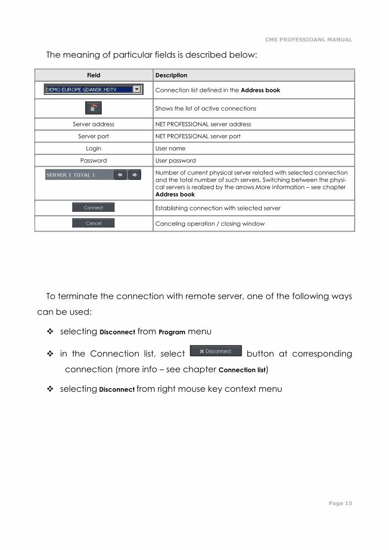
The meaning of particular fields is described below:
Field Description
Connection list defined in the Address book
Shows the list of active connections
Server address NET PROFESSIONAL server address
Server port NET PROFESSIONAL server port
Login User name
Password User password
Number of current physical server related with selected connection
and the total number of such servers. Switching between the physi-
cal servers is realized by the arrows.More information – see chapter
Address book
Establishing connection with selected server
Canceling operation / closing window
To terminate the connection with remote server, one of the following ways
can be used:
selecting Disconnect from Program menu
in the Connection list, select button at corresponding
connection (more info – see chapter Connection list)
selecting Disconnect from right mouse key context menu
Page 16
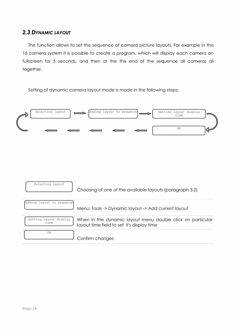
22..33 DDYYNNAAMMIICC LLAAYYOOUUTT
The function allows to set the sequence of camera picture layouts. For example in the
16 camera system it is possible to create a program, which will display each camera on
fullscreen for 5 seconds, and then at the the end of the sequence all cameras all
together.
Setting of dynamic camera layout mode is made in the following steps:
Choosing of one of the available layouts (paragraph 3.2)
Menu: Tools -> Dynamic layout -> Add current layout
When in the dynamic layout menu double click on particular
layout time field to set it's display time
Confirm changes
OK
Setting layout display
time
Adding layout to sequence
Selecting layout
Selecting layout Adding layout to sequence
Setting layout display
time
OK
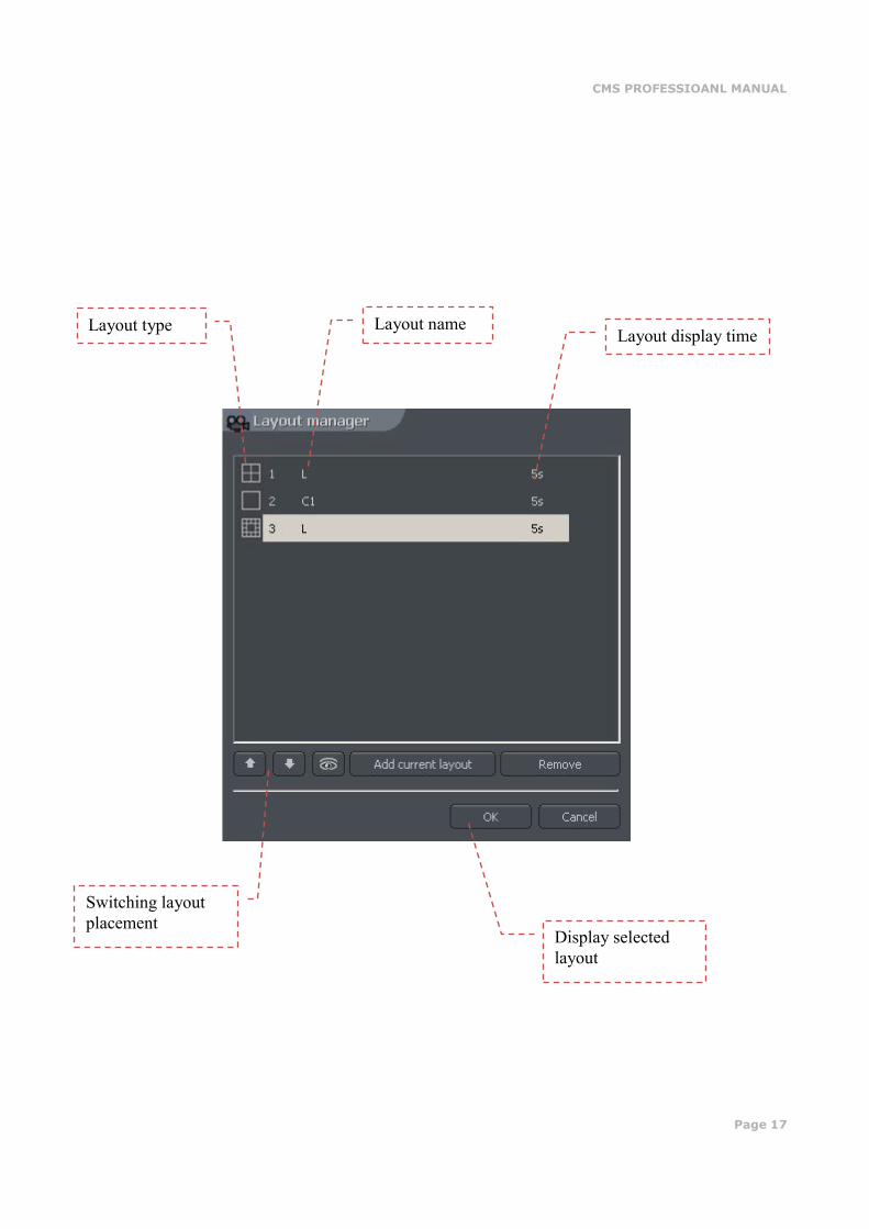
CMS PROFESSIOANL MANUAL
Page 17
Display selected
layout
Switching layout
placement
Layout type Layout name Layout display time

Page 18
33.. SSYYSSTTEEMM TTOOOOLLSS
In this chapter, there will be described client application's tools, such as
Address book and Photo Browser. One of most important tools is the Archive
browser. The multitude of included functions allows to quickly find particular
events, prepare backup copies and export recording to popular .avi format.
The efficiency of archives depends mainly on hardware specification of
the computer (Processor, HDD interface, RAM memory).
CMS PROFESSIOANL MANUAL
Page 19
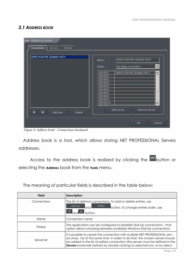
33..11 AADDDDRREESSSS BBOOOOKK
Address book is a tool, which allows storing NET PROFESSIONAL Servers
addresses.
Access to the address book is realized by clicking the button or
selecting the Address book from the Tools menu.
The meaning of particular fields is described in the table below:
Field Description
Connections The list of defined connections. To add or delete entries, use
and button. To change entries order, use
and button.
Name Connection name
Dialup The application can be configured to establish Dial-Up connections – that
option allows choosing between available Windows Dial-Up connections.
Server list
It is possible to create the connection with multiple NET PROFESSIONAL serv-
ers (max. 16) at the same time. In order to do that, the chosen servers should
be added to the list of edited connection (the servers must be defined in the
Servers bookmark before) by double clicking on selected row, or by select-
Figure 4: Address book – Connections bookmark
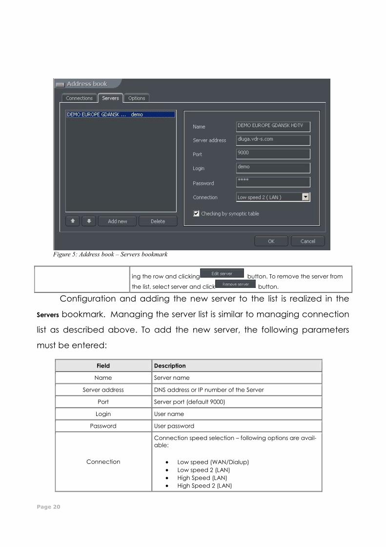
Page 20
ing the row and clicking button. To remove the server from
the list, select server and click button.
Configuration and adding the new server to the list is realized in the
Servers bookmark. Managing the server list is similar to managing connection
list as described above. To add the new server, the following parameters
must be entered:
Field Description
Name Server name
Server address DNS address or IP number of the Server
Port Server port (default 9000)
Login User name
Password User password
Connection
Connection speed selection – following options are avail-
able:
Low speed (WAN/Dialup)
Low speed 2 (LAN)
High Speed (LAN)
High Speed 2 (LAN)
Figure 5: Address book – Servers bookmark
CMS PROFESSIOANL MANUAL
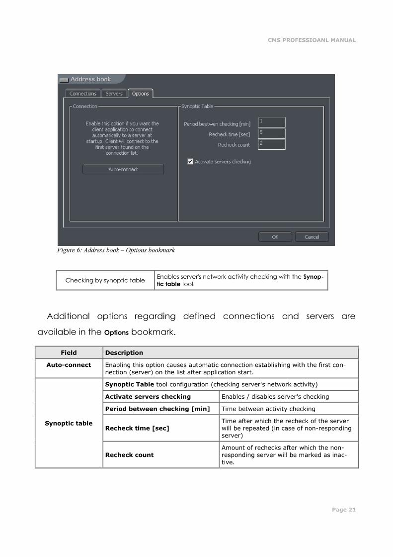
Page 21
Checking by synoptic table Enables server's network activity checking with the Synop-
tic table tool.
Additional options regarding defined connections and servers are
available in the Options bookmark.
Field Description
Auto-connect Enabling this option causes automatic connection establishing with the first con-
nection (server) on the list after application start.
Synoptic table
Synoptic Table tool configuration (checking server's network activity)
Activate servers checking Enables / disables server's checking
Period between checking [min] Time between activity checking
Recheck time [sec] Time after which the recheck of the server will be repeated (in case of non-responding server)
Recheck count Amount of rechecks after which the non-responding server will be marked as inac-tive.
Figure 6: Address book – Options bookmark

Page 22
33..11 CCOONNNNEECCTTIIOONN LLIISSTT
The list showing all active server connections. Allows terminating /
establishing new connections, and displays (if necessary) additional
informations regarding communication / establishing connection.
Figure 7: Connection list
CMS PROFESSIOANL MANUAL
Page 23
33..22 AARRCCHHIIVVEE BBRROOWWSSEERR
The CMS application includes an advanced tool for browsing, recording
and exporting archive recordings. It allows accessing the remote server's
recordings, as well as local recording of remotely viewed videos. In the Tools
menu, there are 3 options regarding the archives:
Remote archives – access to the selected remote server's archive
Local archives – access to the local archives – creating and configuration of local disk
space required – see chapter Disk Archive
Archives from path – access to archives in selected folder (e.g. backup copy from server). In
the dialog box should be the archive index folder selected (default svrVideoIndex).
To access the archive tool, do one of the following:
select the keyboard shortcut Ctrl+A (the local archive is opened)
in the Tools menu select one of above described options
click the icon (additional dialog box with archive type selection will be displayed
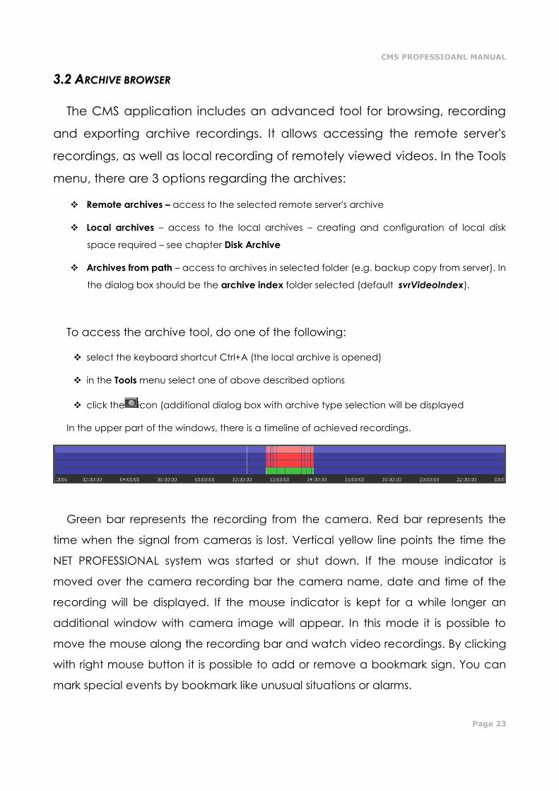
In the upper part of the windows, there is a timeline of achieved recordings.
Green bar represents the recording from the camera. Red bar represents the
time when the signal from cameras is lost. Vertical yellow line points the time the
NET PROFESSIONAL system was started or shut down. If the mouse indicator is
moved over the camera recording bar the camera name, date and time of the
recording will be displayed. If the mouse indicator is kept for a while longer an
additional window with camera image will appear. In this mode it is possible to
move the mouse along the recording bar and watch video recordings. By clicking
with right mouse button it is possible to add or remove a bookmark sign. You can
mark special events by bookmark like unusual situations or alarms.
Page 24
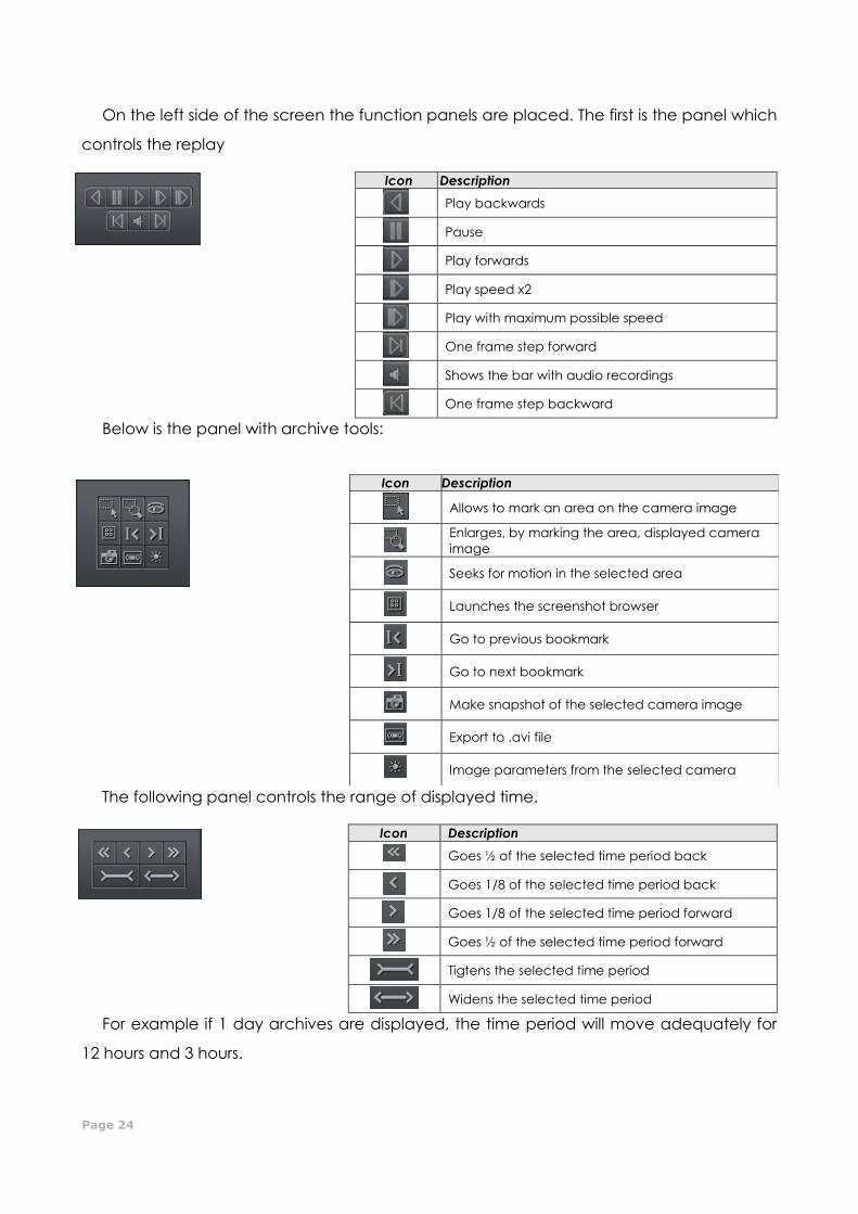
On the left side of the screen the function panels are placed. The first is the panel which
controls the replay
Icon Description
Play backwards
Pause
Play forwards
Play speed x2
Play with maximum possible speed
One frame step forward
Shows the bar with audio recordings
One frame step backward
Below is the panel with archive tools:
Icon Description
Allows to mark an area on the camera image
Enlarges, by marking the area, displayed camera
image
Seeks for motion in the selected area
Launches the screenshot browser
Go to previous bookmark
Go to next bookmark
Make snapshot of the selected camera image
Export to .avi file
Image parameters from the selected camera
The following panel controls the range of displayed time.
Icon Description
Goes ½ of the selected time period back
Goes 1/8 of the selected time period back
Goes 1/8 of the selected time period forward
Goes ½ of the selected time period forward
Tigtens the selected time period
Widens the selected time period
For example if 1 day archives are displayed, the time period will move adequately for
12 hours and 3 hours.
CMS PROFESSIOANL MANUAL
Page 25
Function buttons are described below:
Show a whole day – shows a whole day recordings
Calendar – launches calendar
Backup – launches the backup copy tool
33..22..11 SSEEAARRCCHHIINNGG FFOORR MMOOTTIIOONN IINN TTHHEE AARRCCHHIIVVEE RREECCOORRDDIINNGGSS
NET PROFESSIONAL system allows to search for motion in the recorded
video. It is possible to select particular area on the camera image. To search
for motion click icon and select the area or whole image. To start the
search procedure click icon.
System will start to play the video. If the motion is detected it will stop
playing the video, which will indicate motion. Additionally the system will
play sound. User can also control the motion sensitivity during the search
by clicking and moving the first bar (motion search level) in the panel. To
search further click again.
33..22..22 EEXXPPOORRTT TTOO ..AAVVII
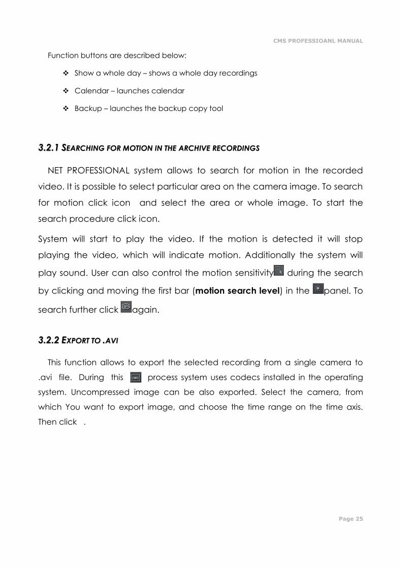
This function allows to export the selected recording from a single camera to
.avi file. During this process system uses codecs installed in the operating
system. Uncompressed image can be also exported. Select the camera, from
which You want to export image, and choose the time range on the time axis.
Then click .
Page 26
Figure 8: Archive – export to .avi
In this window user can set number of frames per second or if camera name
and time will be put in the .avi video. The next step is to name the file. After these
actions click OK. The following step is to choose codec for image compression.
You can choose one of the codecs installed in Windows OS. You can resign from
image compression by selecting Full frames (uncompressed). The export process
can take some time. It depends on video length, compression level and CPU
computational power.
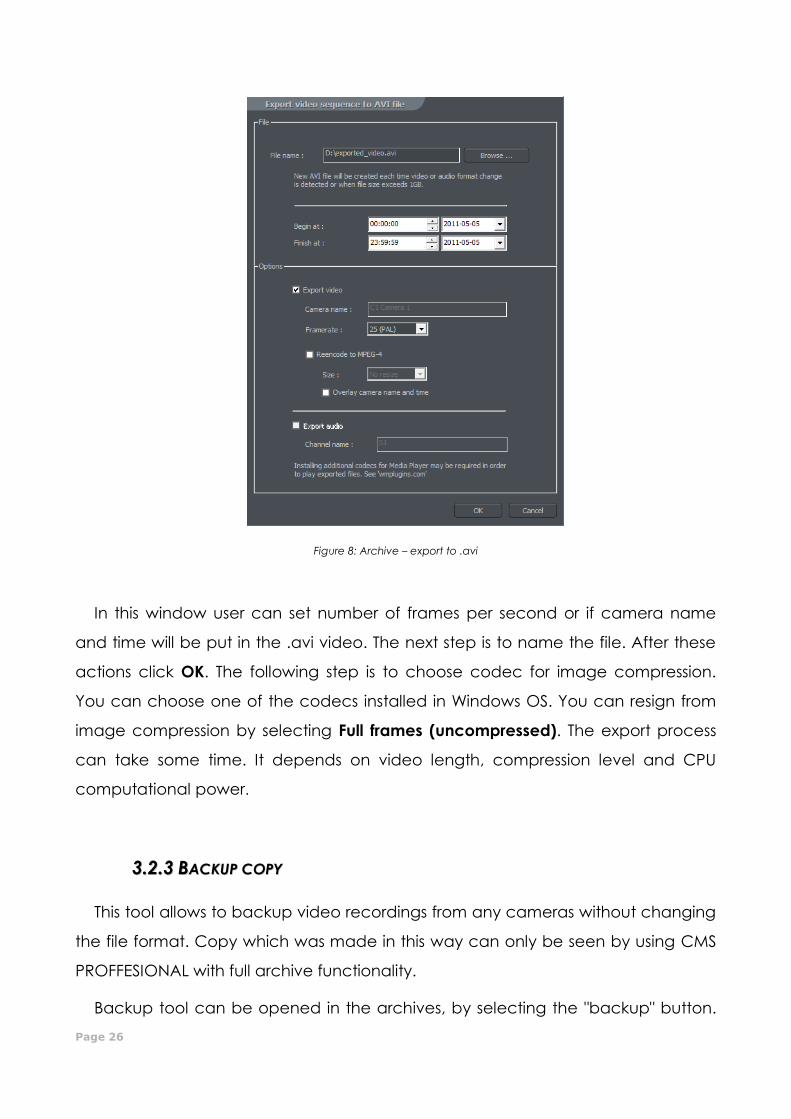
33..22..33 BBAACCKKUUPP CCOOPPYY
This tool allows to backup video recordings from any cameras without changing
the file format. Copy which was made in this way can only be seen by using CMS
PROFFESIONAL with full archive functionality.
Backup tool can be opened in the archives, by selecting the "backup" button.
CMS PROFESSIOANL MANUAL
Page 27
Next it's necessary to type login and password of user with rights to perform the
"backup", and chose one of the options:
Backup media files – performs archive backup copy
Delete media files – deleting archive files
Change backup settings – change of settings of backup function
In order to make the archive backup copy, first path to the designated folder must
be entered, to which the archive files will be copied, then select the cameras and
sound source, from which the recording will be archived.
Next stage is selecting the time range of the recordings. After that, the program
will show required and free space in the specified location of the disk and will start
the backup process.
Figure 9: Archive browser – Backup – Camera selection
Page 28
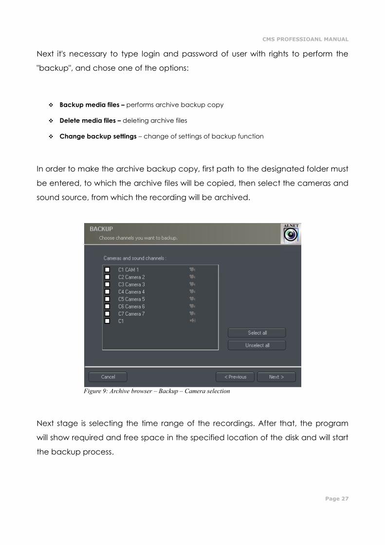
After creating the backup copy, backup application will show the summary of
made operations, and end action.
Creating backup copy can be very long-lasting and CPU power demanding
process. It is recommended to create backup copy when the system is not heavy
loaded, for example in evening hours where there is less motion.
Figure 10: Archive browser - Backup
CMS PROFESSIOANL MANUAL
Page 29
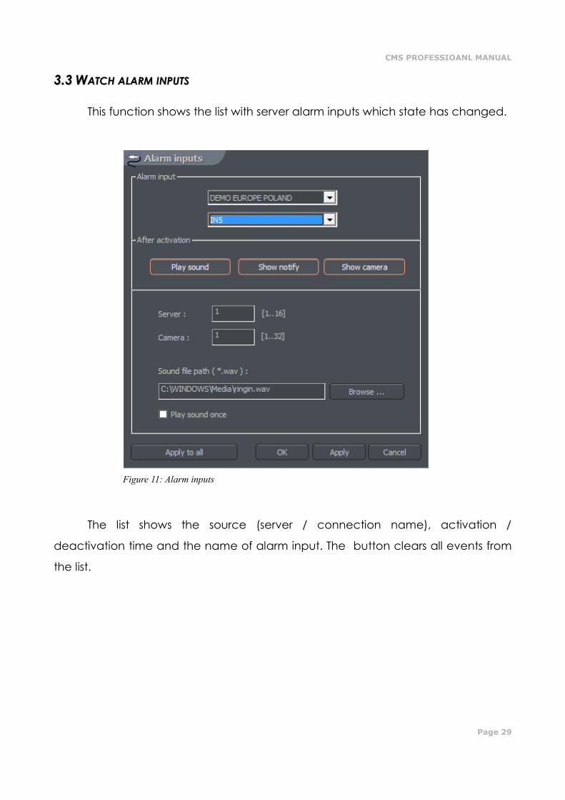
33..33 WWAATTCCHH AALLAARRMM IINNPPUUTTSS
This function shows the list with server alarm inputs which state has changed.
The list shows the source (server / connection name), activation /
deactivation time and the name of alarm input. The button clears all events from
the list.
Figure 11: Alarm inputs
Page 30
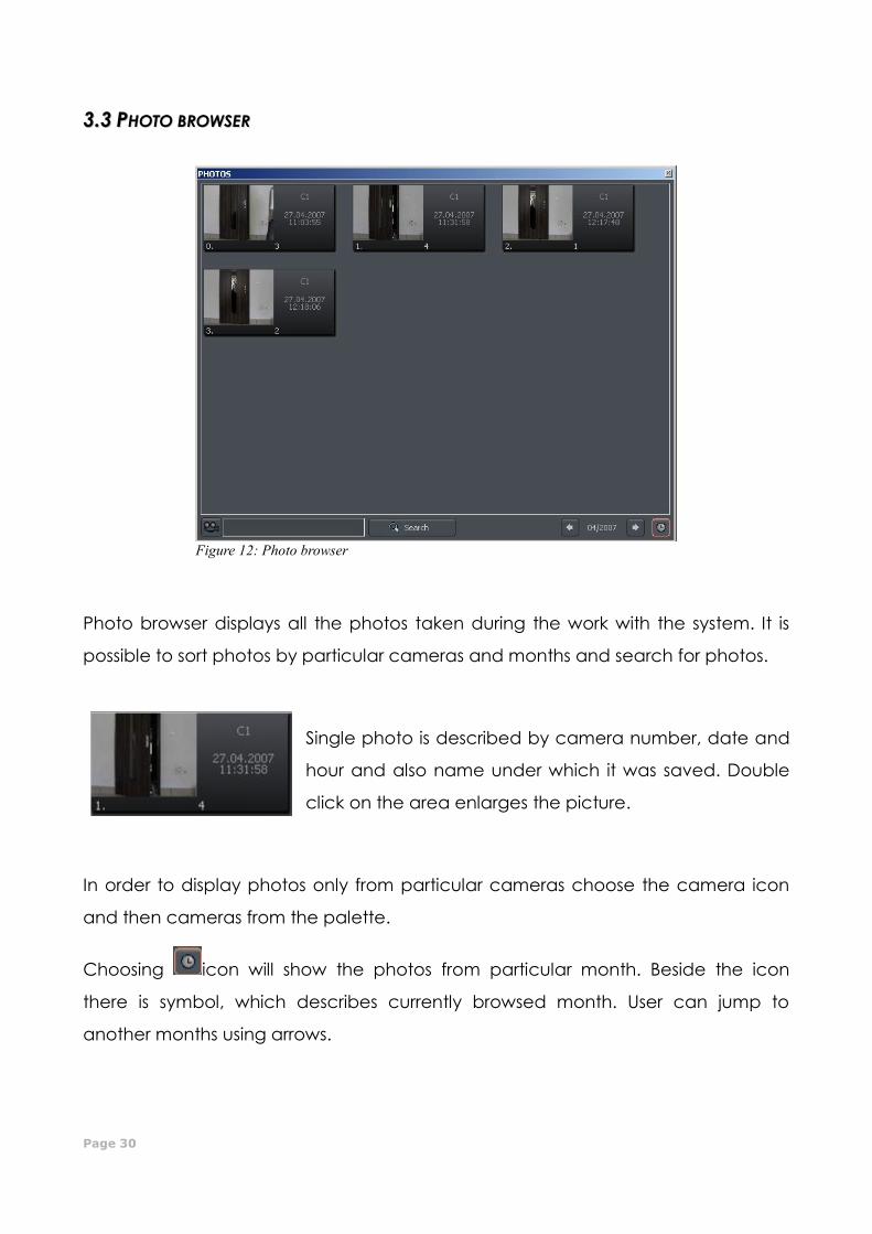
33..33 PPHHOOTTOO BBRROOWWSSEERR
Photo browser displays all the photos taken during the work with the system. It is
possible to sort photos by particular cameras and months and search for photos.
Single photo is described by camera number, date and
hour and also name under which it was saved. Double
click on the area enlarges the picture.
In order to display photos only from particular cameras choose the camera icon
and then cameras from the palette.
Choosing icon will show the photos from particular month. Beside the icon
there is symbol, which describes currently browsed month. User can jump to
another months using arrows.
Figure 12: Photo browser
CMS PROFESSIOANL MANUAL
Page 31
After filling the text field and clicking Search system will display pictures which
name includes the submitted sequence of signs. Additionally it is possible to delete
photos from the browser level. To this select picture and press Delete key on
keyboard.
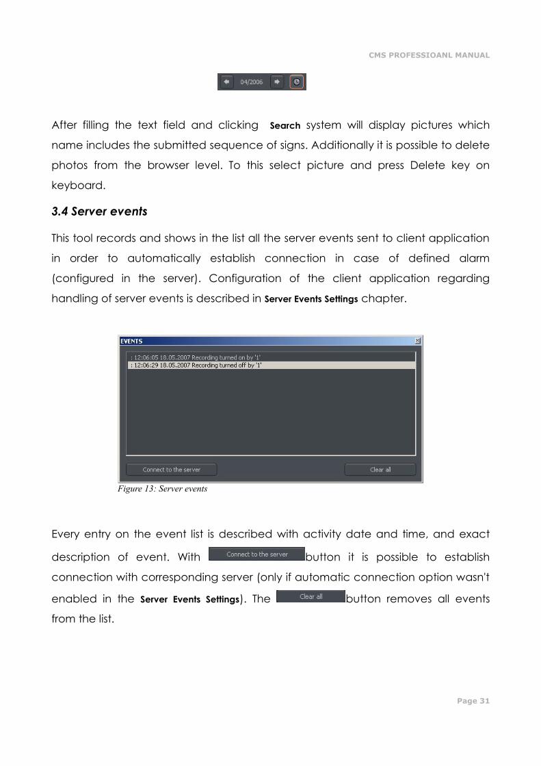
3.4 Server events
This tool records and shows in the list all the server events sent to client application
in order to automatically establish connection in case of defined alarm
(configured in the server). Configuration of the client application regarding
handling of server events is described in Server Events Settings chapter.
Every entry on the event list is described with activity date and time, and exact
description of event. With button it is possible to establish
connection with corresponding server (only if automatic connection option wasn't
enabled in the Server Events Settings). The button removes all events
from the list.
Figure 13: Server events
Page 32
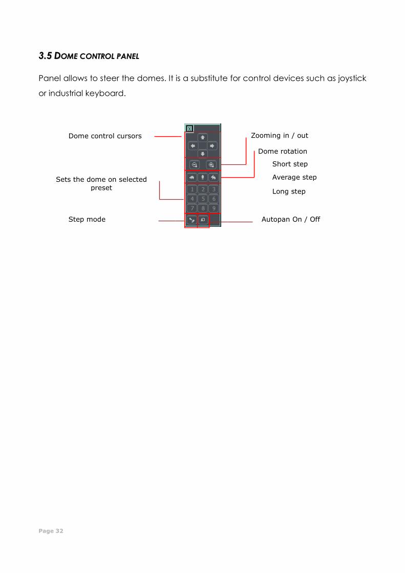
33..55 DDOOMMEE CCOONNTTRROOLL PPAANNEELL
Panel allows to steer the domes. It is a substitute for control devices such as joystick
or industrial keyboard.
Dome control cursors Zooming in / out
Dome rotation
Short step
Average step
Long step
Sets the dome on selected
preset
Step mode Autopan On / Off
CMS PROFESSIOANL MANUAL
Page 33
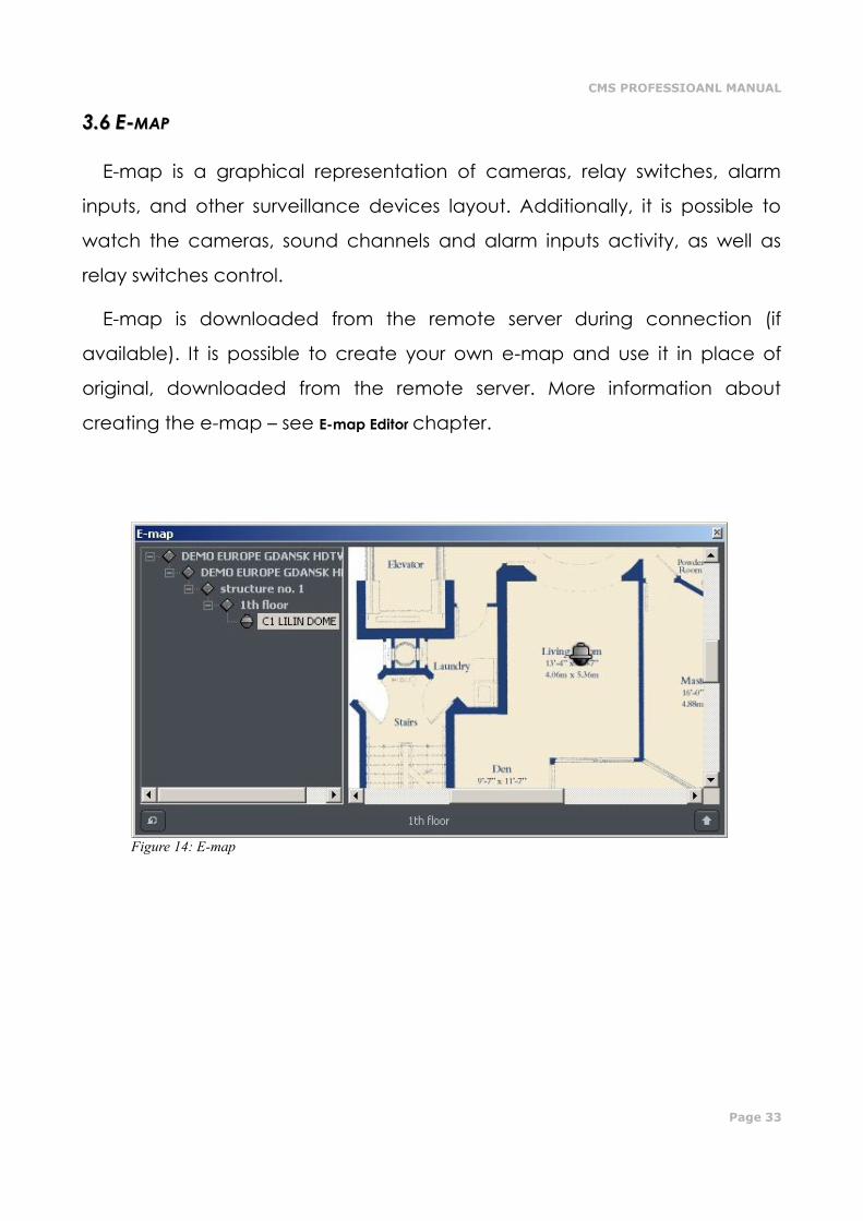
33..66 EE--MMAAPP
E-map is a graphical representation of cameras, relay switches, alarm
inputs, and other surveillance devices layout. Additionally, it is possible to
watch the cameras, sound channels and alarm inputs activity, as well as
relay switches control.
E-map is downloaded from the remote server during connection (if
available). It is possible to create your own e-map and use it in place of
original, downloaded from the remote server. More information about
creating the e-map – see E-map Editor chapter.
Figure 14: E-map
Page 34
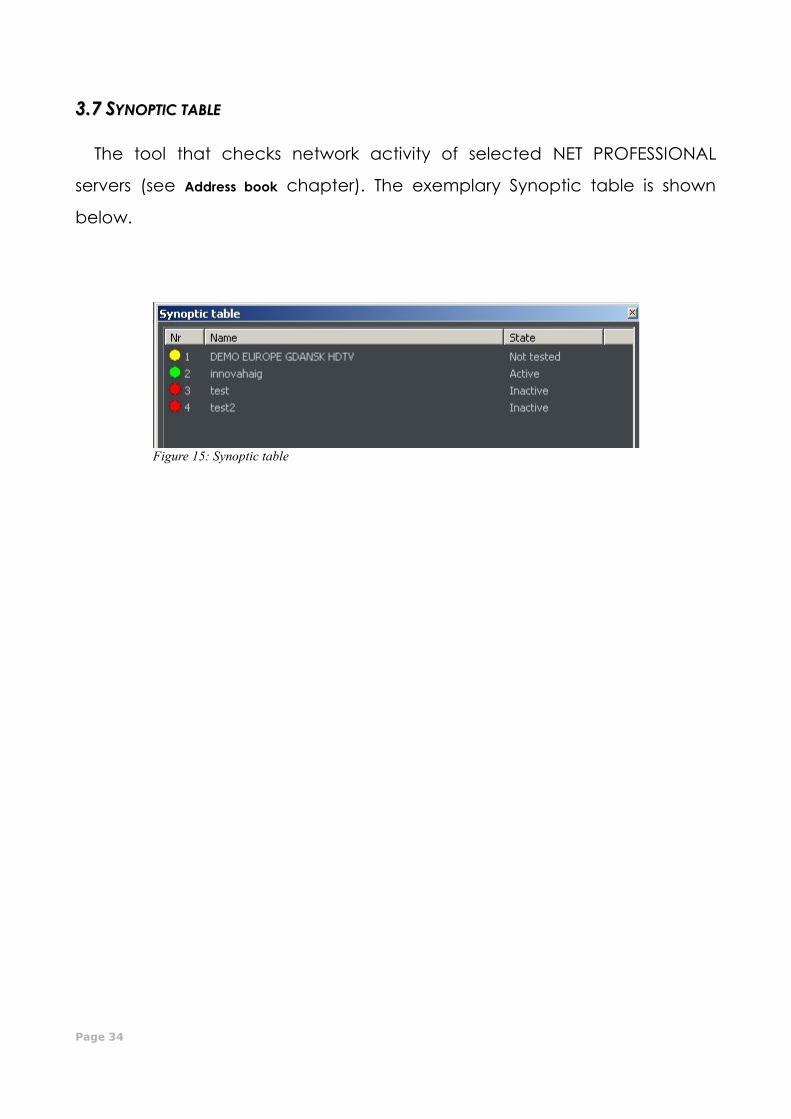
33..77 SSYYNNOOPPTTIICC TTAABBLLEE
The tool that checks network activity of selected NET PROFESSIONAL
servers (see Address book chapter). The exemplary Synoptic table is shown
below.
Figure 15: Synoptic table
CMS PROFESSIOANL MANUAL
Page 35
44.. PPRROOGGRRAAMM SSEETTTTIINNGGSS
In this chapter there will be described configuration options of NET
PROFESSIONAL System client application. Please pay your attention to
subchapter regarding cameras configuration and archive storage settings.
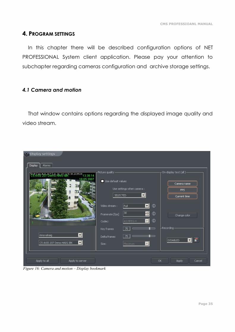
4.1 Camera and motion
That window contains options regarding the displayed image quality and
video stream.
Figure 16: Camera and motion – Display bookmark
Page 36
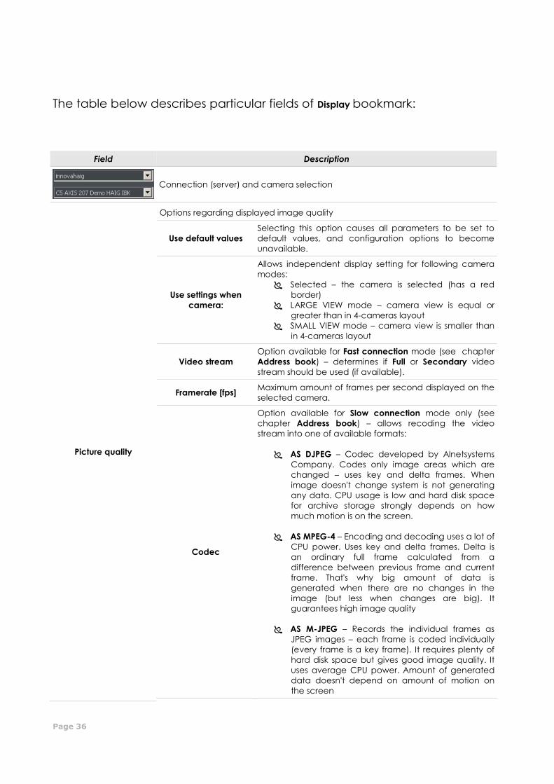
The table below describes particular fields of Display bookmark:
Field Description
Connection (server) and camera selection
Picture quality
Options regarding displayed image quality
Use default values
Selecting this option causes all parameters to be set to
default values, and configuration options to become
unavailable.
Use settings when
camera:
Allows independent display setting for following camera
modes:
Selected – the camera is selected (has a red
border)
LARGE VIEW mode – camera view is equal or
greater than in 4-cameras layout
SMALL VIEW mode – camera view is smaller than
in 4-cameras layout
Video stream
Option available for Fast connection mode (see chapter
Address book) – determines if Full or Secondary video
stream should be used (if available).
Framerate [fps] Maximum amount of frames per second displayed on the
selected camera.
Codec
Option available for Slow connection mode only (see
chapter Address book) – allows recoding the video
stream into one of available formats:
AS DJPEG – Codec developed by Alnetsystems
Company. Codes only image areas which are
changed – uses key and delta frames. When
image doesn't change system is not generating
any data. CPU usage is low and hard disk space
for archive storage strongly depends on how
much motion is on the screen.
AS MPEG-4 – Encoding and decoding uses a lot of
CPU power. Uses key and delta frames. Delta is
an ordinary full frame calculated from a
difference between previous frame and current
frame. That's why big amount of data is
generated when there are no changes in the
image (but less when changes are big). It
guarantees high image quality
AS M-JPEG – Records the individual frames as
JPEG images – each frame is coded individually
(every frame is a key frame). It requires plenty of
hard disk space but gives good image quality. It
uses average CPU power. Amount of generated
data doesn't depend on amount of motion on
the screen
CMS PROFESSIOANL MANUAL
Page 37
Key frames
Quality of key frames, which are background to delta
frames. The higher value the higher quality (and more
hard disk space needed for the archives)
Delta frames Quality of Delta frames (the part of the image which
changes)
Size Video frame size
On display text (all)
Informations displayed on every camera image
Camera name Camera name
FPS Actual frames per second
Current time Current time
Change color Changes color of displayed informations
Recording
Local recording options
Enabled / Disabled Enables / disables local recording for selected camera
Displays the list of all cameras with local recording
enabled
Applies all current settings to all connected cameras
Applies all current settings to server settings (if connected user is allowed to)
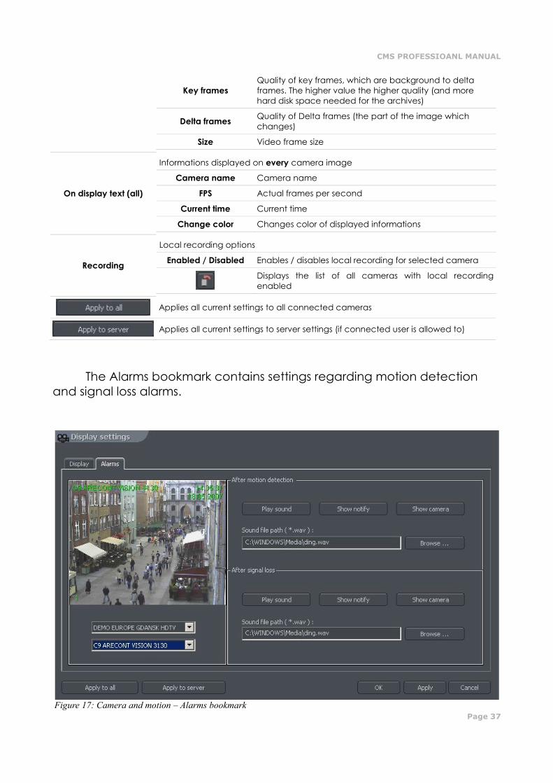
The Alarms bookmark contains settings regarding motion detection
and signal loss alarms.
Figure 17: Camera and motion – Alarms bookmark
Page 38
Description of available options is presented in the table below:
Field Description
Connection (server) and camera selection
After motion detection
Motion detection alarm handling
Play sound Plays sound file
Show notify Shows “Balloon tip” notification
Show camera Shows the camera which activated alarm
event.
Sound file path Path to the sound file which will be played in
case of alarm event.
After signal loss Signal loss alarm handling
Options are similar to these described above
CMS PROFESSIOANL MANUAL
Page 39
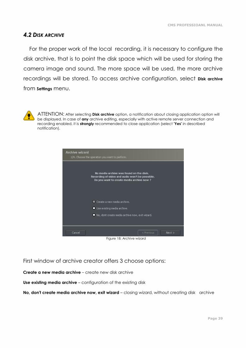
44..22 DDIISSKK AARRCCHHIIVVEE
For the proper work of the local recording, it is necessary to configure the
disk archive, that is to point the disk space which will be used for storing the
camera image and sound. The more space will be used, the more archive
recordings will be stored. To access archive configuration, select Disk archive
from Settings menu.
ATTENTION: After selecting Disk archive option, a notification about closing application option will
be displayed. In case of any archive editing, especially with active remote server connection and
recording enabled, it is strongly recommended to close application (select 'Yes' in described
notification).
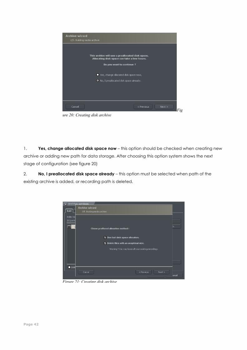
Figure 18: Archive wizard
First window of archive creator offers 3 choose options:
Create a new media archive – create new disk archive
Use existing media archive – configuration of the existing disk
No, don't create media archive now, exit wizard – closing wizard, without creating disk archive
Figure 17: Creating disk archive
Page 40
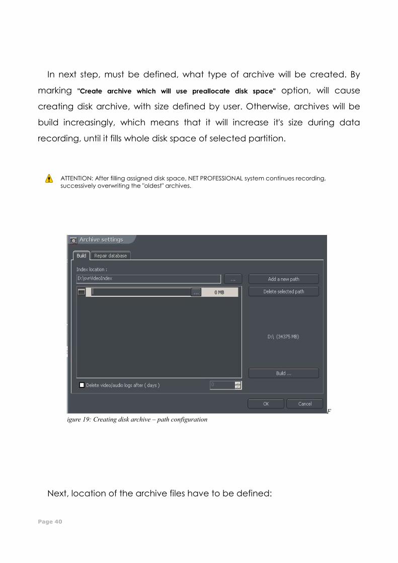
In next step, must be defined, what type of archive will be created. By
marking "Create archive which will use preallocate disk space" option, will cause
creating disk archive, with size defined by user. Otherwise, archives will be
build increasingly, which means that it will increase it's size during data
recording, until it fills whole disk space of selected partition.
ATTENTION: After filling assigned disk space, NET PROFESSIONAL system continues recording,
successively overwriting the "oldest" archives.
Next, location of the archive files have to be defined:
F
igure 19: Creating disk archive – path configuration
CMS PROFESSIOANL MANUAL
Page 41
1. Index folder path - this folder contains information about stored archives - it must be defined
in the first place.
2. Archive folder path - in defined folder archives will be stored. At the same time,
configuration of multiple archive path's is possible.
3. Size of disk archives - defined size of archive folder - changing is possible after double-click
on numerical value.
ATTENTION: 1. Option presented above is available only when the disk archive is created with preallocated disk
space (see figure 10). If the increasing archive is created the option will not be available.
2. Minimum disk space cannot be lower than:
[number of connected cameras] x 32 MB,
- lower disk space can cause recording malfunctions.
4. Adding path to archive – allows to add another paths to disk archive
5. Deleting archive path – erases the selected disk archive path
6. Declaring the available archive size on selected disk partition
7. Creating archive – after defining index paths and archive use this option to create archive
for the recordings
8. Erasing recordings older than defined number of days
Clicking OK button after defining the paths to index folder and disk
archives folder will make system to proceed to the next stage of archive
configuration:
Page 42
1. Yes, change allocated disk space now – this option should be checked when creating new
archive or adding new path for data storage. After choosing this option system shows the next
stage of configuration (see figure 20)
2. No, I preallocated disk space already – this option must be selected when path of the
existing archive is added, or recording path is deleted.
Fig
ure 20: Creating disk archive
Figure 21: Creating disk archive
CMS PROFESSIOANL MANUAL
Page 43
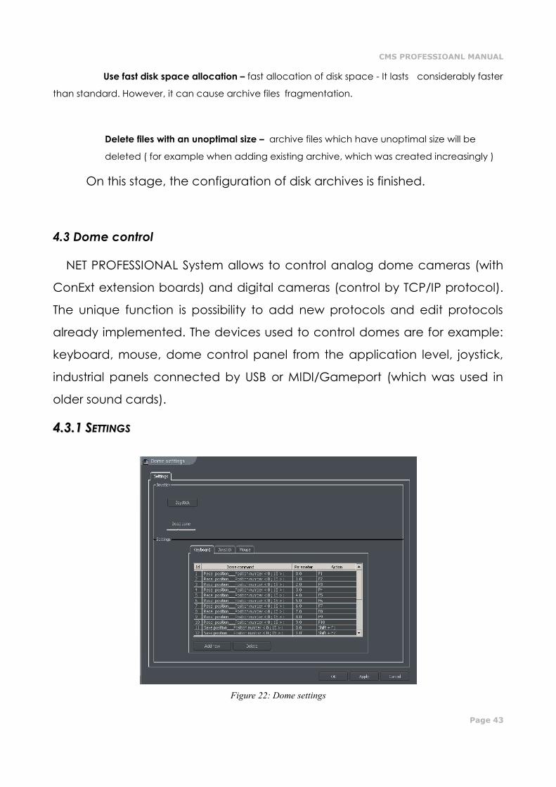
Use fast disk space allocation – fast allocation of disk space - It lasts considerably faster
than standard. However, it can cause archive files fragmentation.
Delete files with an unoptimal size – archive files which have unoptimal size will be
deleted ( for example when adding existing archive, which was created increasingly )
On this stage, the configuration of disk archives is finished.
4.3 Dome control
NET PROFESSIONAL System allows to control analog dome cameras (with
ConExt extension boards) and digital cameras (control by TCP/IP protocol).
The unique function is possibility to add new protocols and edit protocols
already implemented. The devices used to control domes are for example:
keyboard, mouse, dome control panel from the application level, joystick,
industrial panels connected by USB or MIDI/Gameport (which was used in
older sound cards).
44..33..11 SSEETTTTIINNGGSS
Figure 22: Dome settings
Page 44
Panel Field Description
Joystick Joystick Activates joystick. If any error occurs the message will appear
Dead zone Joystick "motion range" on which system will not react
Settings Settings which concern control commands. This panel is divided into three sections:
Keyboard, Joystick and Mouse. It is possible to add new command and edit existing ones. To
edit command double-click on command name. To add command select "Add new"
button
Dome command Command name (describes it's action)
Parameter Parameter value, which is transmitted to the dome during the
command execution
Action Keyboard shortcut to selected command (for mouse and joystick
these options are permanently assigned to their functions)
CMS PROFESSIOANL MANUAL
Page 45
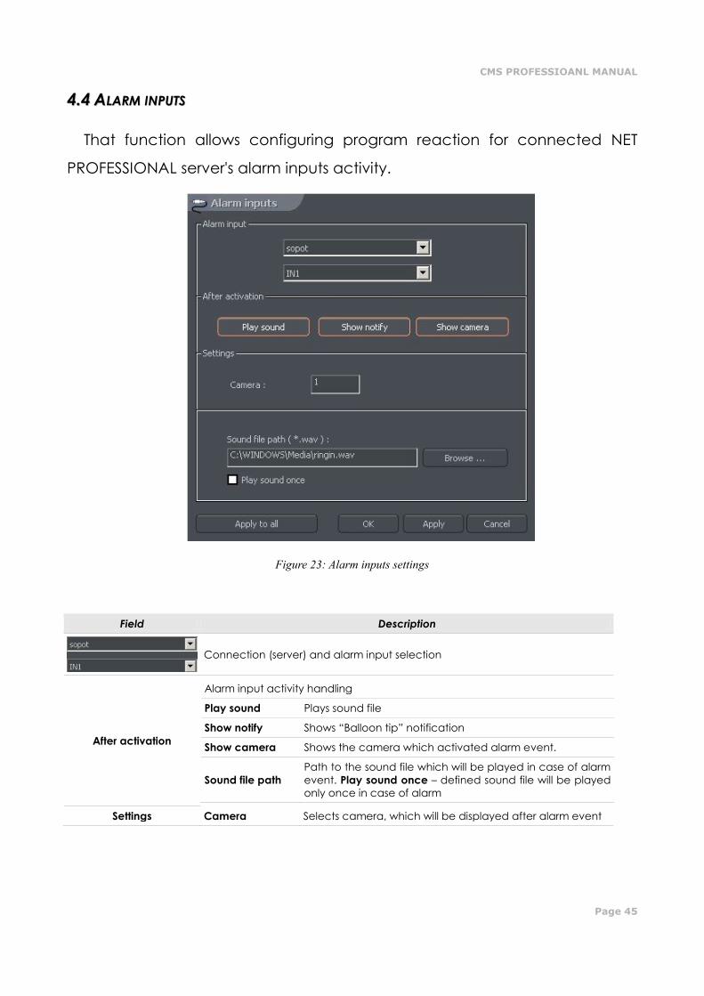
44..44 AALLAARRMM IINNPPUUTTSS
That function allows configuring program reaction for connected NET
PROFESSIONAL server's alarm inputs activity.
Figure 23: Alarm inputs settings
Field Description
Connection (server) and alarm input selection
After activation
Alarm input activity handling
Play sound Plays sound file
Show notify Shows “Balloon tip” notification
Show camera Shows the camera which activated alarm event.
Sound file path
Path to the sound file which will be played in case of alarm
event. Play sound once – defined sound file will be played
only once in case of alarm
Settings Camera Selects camera, which will be displayed after alarm event
Page 46
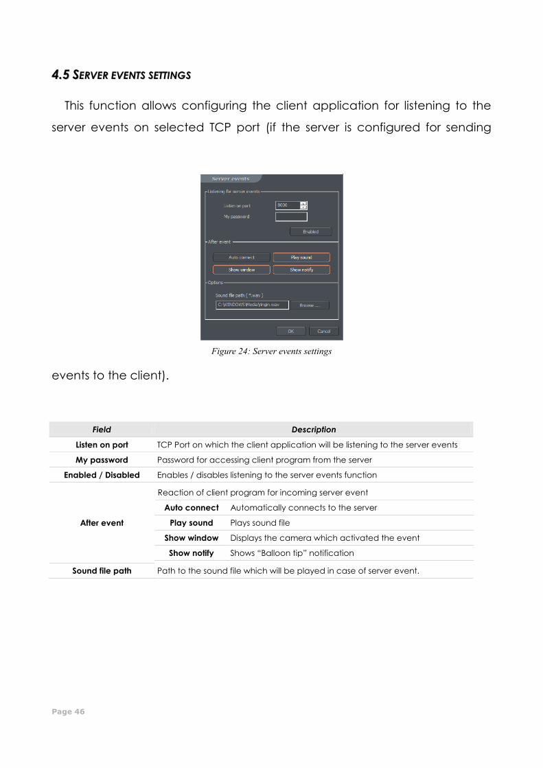
44..55 SSEERRVVEERR EEVVEENNTTSS SSEETTTTIINNGGSS
This function allows configuring the client application for listening to the
server events on selected TCP port (if the server is configured for sending
events to the client).
Field Description
Listen on port TCP Port on which the client application will be listening to the server events
My password Password for accessing client program from the server
Enabled / Disabled Enables / disables listening to the server events function
After event
Reaction of client program for incoming server event
Auto connect Automatically connects to the server
Play sound Plays sound file
Show window Displays the camera which activated the event
Show notify Shows “Balloon tip” notification
Sound file path Path to the sound file which will be played in case of server event.
Figure 24: Server events settings
CMS PROFESSIOANL MANUAL
Page 47
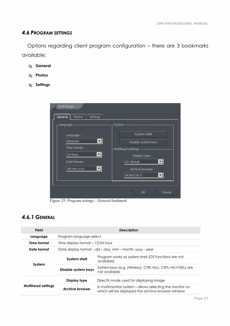
44..66 PPRROOGGRRAAMM SSEETTTTIINNGGSS
Options regarding client program configuration – there are 3 bookmarks
available:
General
Photos
Settings
44..66..11 GGEENNEERRAALL
Field Description
Language Program language select
Time format Time display format – 12/24 hour
Date format Date display format – dd – day, mm – month, yyyy - year
System
System shell Program works as system shell (OS functions are not
available)
Disable system keys System keys (e.g. [Winkey], CTRL+Esc, CRTL+ALT+DEL) are
not available
Multihead settings
Display type DirectX mode used for displaying image
Archive browser In multimonitor system – allows selecting the monitor on
which will be displayed the archive browser window
Figure 25: Program settings – General bookmark
Page 48
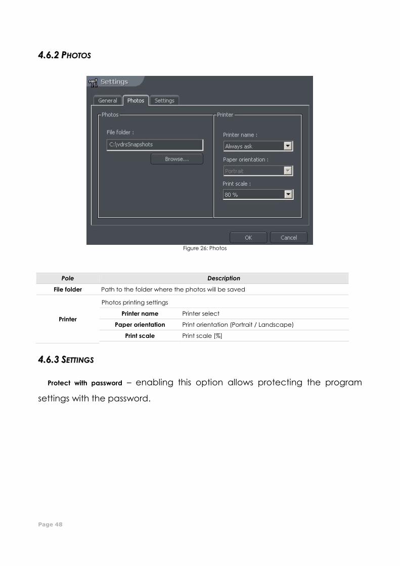
44..66..22 PPHHOOTTOOSS
Figure 26: Photos
Pole Description
File folder Path to the folder where the photos will be saved
Printer
Photos printing settings
Printer name Printer select
Paper orientation Print orientation (Portrait / Landscape)
Print scale Print scale [%]
44..66..33 SSEETTTTIINNGGSS
Protect with password – enabling this option allows protecting the program
settings with the password.
Figure 25: Program settings – Photos bookmark

CMS PROFESSIOANL MANUAL
Page 49
44..77 EE--MMAAPP EEDDIITTOORR
E-map is a tool which allows to design a graphic plan of cameras, switches and alarm inputs
placement. Additionally it is possible to activate switches, monitor the activity of alarm inputs, cameras and
sound channels. Graphic files (.jpg .gif .png) can be used as E-map background. E-map editor can be
accessed from menu panel:
Configuration -> E-map editor
E-map can have a tree structure. An example is presented on the next page:
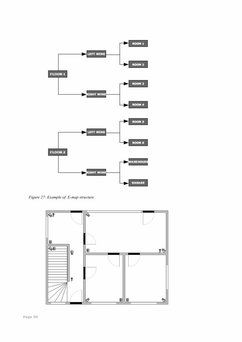
Page 50
Figure 27: Example of E-map structure
CMS PROFESSIOANL MANUAL
Page 51
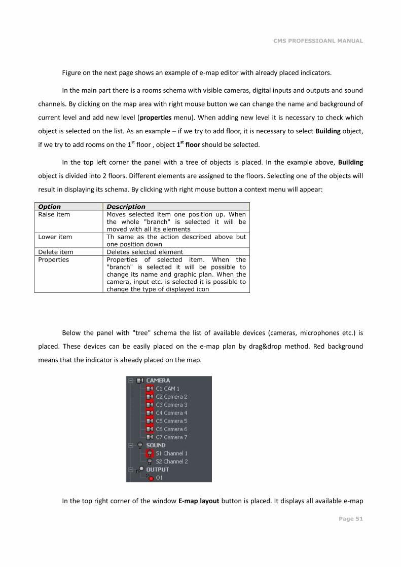
Figure on the next page shows an example of e-map editor with already placed indicators.
In the main part there is a rooms schema with visible cameras, digital inputs and outputs and sound
channels. By clicking on the map area with right mouse button we can change the name and background of
current level and add new level (properties menu). When adding new level it is necessary to check which
object is selected on the list. As an example – if we try to add floor, it is necessary to select Building object,
if we try to add rooms on the 1st floor , object 1st floor should be selected.
In the top left corner the panel with a tree of objects is placed. In the example above, Building
object is divided into 2 floors. Different elements are assigned to the floors. Selecting one of the objects will
result in displaying its schema. By clicking with right mouse button a context menu will appear:
Option Description
Raise item Moves selected item one position up. When
the whole "branch" is selected it will be moved with all its elements
Lower item Th same as the action described above but one position down
Delete item Deletes selected element
Properties Properties of selected item. When the
"branch" is selected it will be possible to change its name and graphic plan. When the camera, input etc. is selected it is possible to change the type of displayed icon
Below the panel with "tree" schema the list of available devices (cameras, microphones etc.) is
placed. These devices can be easily placed on the e-map plan by drag&drop method. Red background
means that the indicator is already placed on the map.
In the top right corner of the window E-map layout button is placed. It displays all available e-map
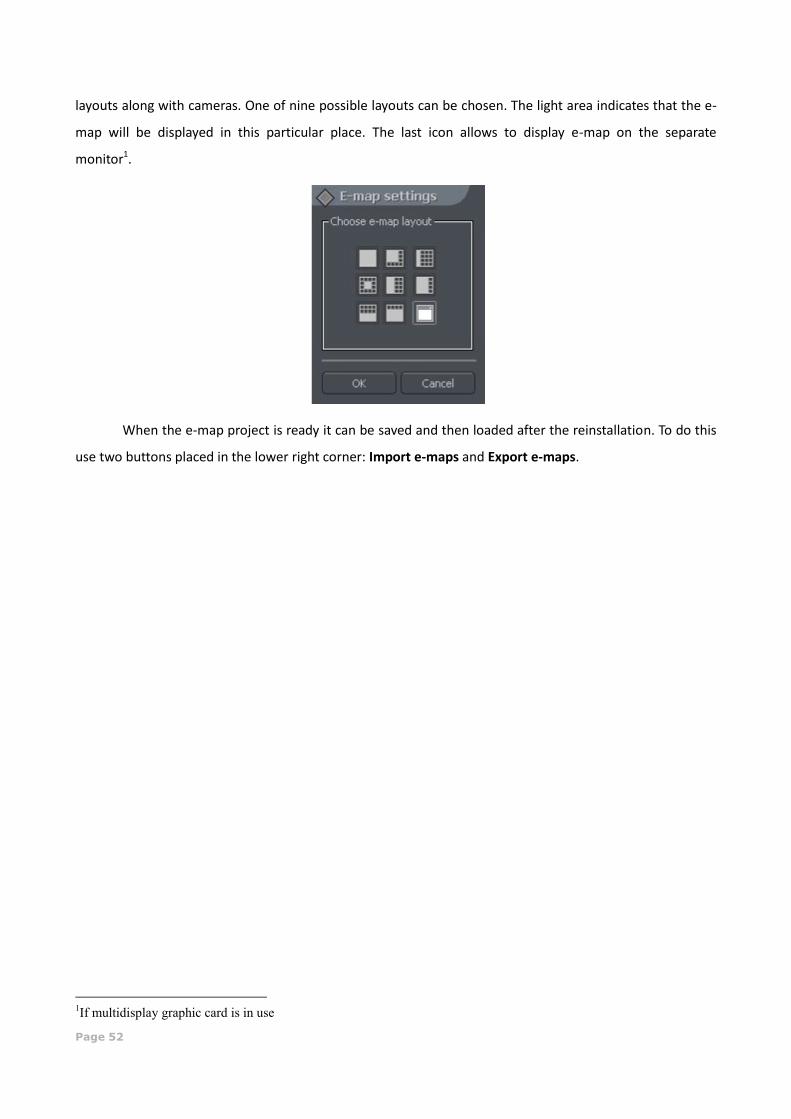
Page 52
layouts along with cameras. One of nine possible layouts can be chosen. The light area indicates that the e-
map will be displayed in this particular place. The last icon allows to display e-map on the separate
monitor1.
When the e-map project is ready it can be saved and then loaded after the reinstallation. To do this
use two buttons placed in the lower right corner: Import e-maps and Export e-maps.
1If multidisplay graphic card is in use
CMS PROFESSIOANL MANUAL
Page 53
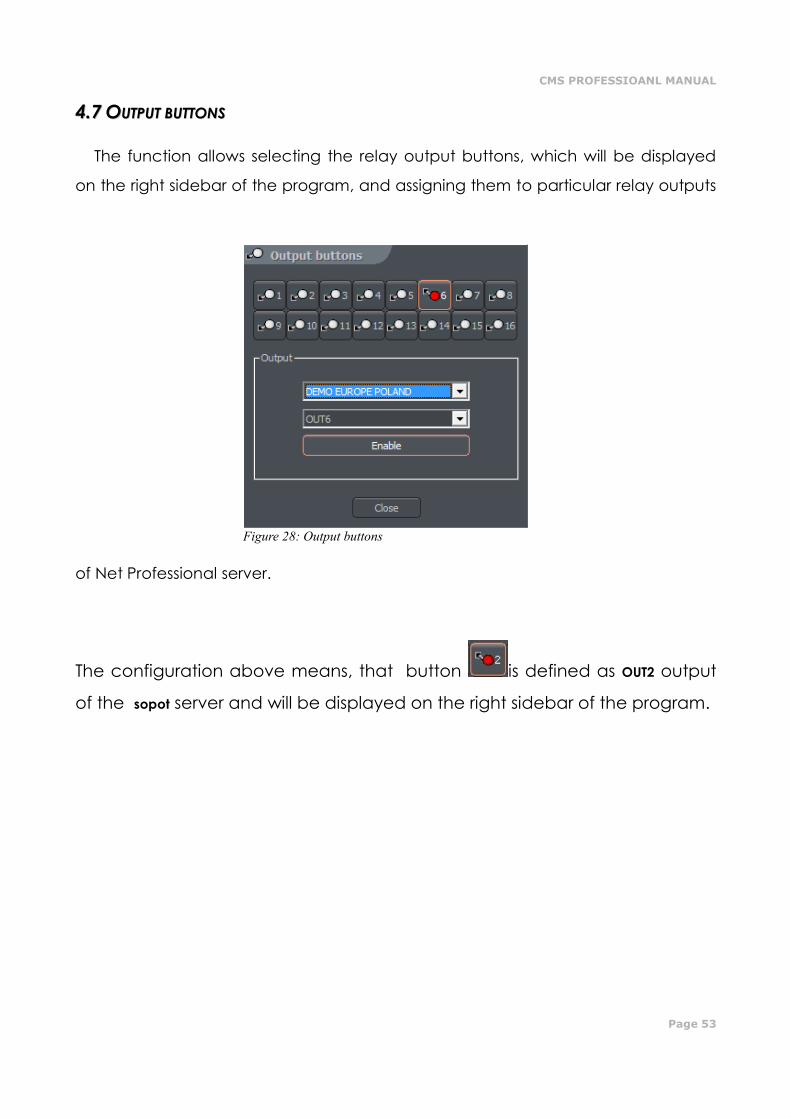
44..77 OOUUTTPPUUTT BBUUTTTTOONNSS
The function allows selecting the relay output buttons, which will be displayed
on the right sidebar of the program, and assigning them to particular relay outputs
of Net Professional server.
The configuration above means, that button is defined as OUT2 output
of the sopot server and will be displayed on the right sidebar of the program.
Figure 28: Output buttons
Page 54
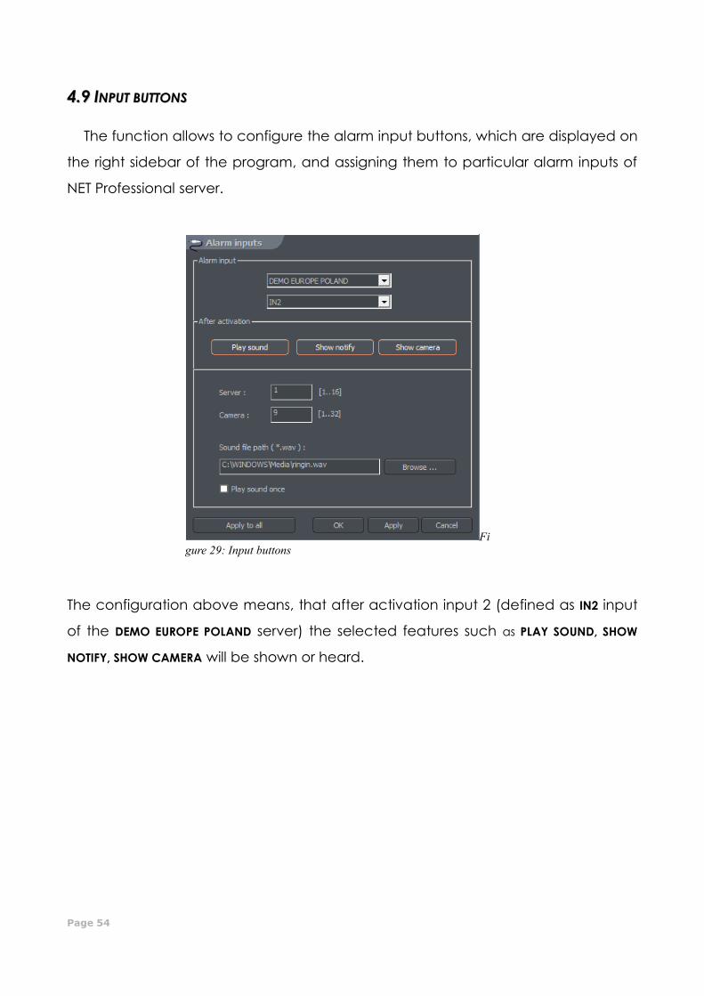
44..99 IINNPPUUTT BBUUTTTTOONNSS
The function allows to configure the alarm input buttons, which are displayed on
the right sidebar of the program, and assigning them to particular alarm inputs of
NET Professional server.
The configuration above means, that after activation input 2 (defined as IN2 input
of the DEMO EUROPE POLAND server) the selected features such as PLAY SOUND, SHOW
NOTIFY, SHOW CAMERA will be shown or heard.
Fi
gure 29: Input buttons
CMS PROFESSIOANL MANUAL
Page 55
44..1100 SSAAVVEE SSEETTTTIINNGGSS
The function saves actual program configuration. It is highly recommended to
save configuration after every configuration change.
Go to settings -> Save settings
4.11 Help
About... - window contains the information about the manufacturer of the
software and program version number.
Figure 30 About CMS