Embed Size (px)
Citation preview
CMT56118 / IDAN-CMT56118
CompactFlash Carrier
utilityModules
User’s Manual
BDM-610020063
Rev. B
IISSOO99000011 aanndd AASS99110000 CCeerrttiiffiieedd

CMT56118 / IDAN-CMT56118
CompactFlash Carrier utilityModules
User’s Manual
RTD Embedded Technologies, Inc.
103 Innovation Blvd.
State College, PA 16803-0906
Phone: +1-814-234-8087
FAX: +1-814-234-5218
web site
www.rtd.com
Revision History
Rev. A New Manual
Rev. B Renamed manual to include “IDAN-CMT56118” in title.
Correct drawings and designators to match PCB revisions 160002451BB (CMT56118).
Removed references to 80-conductor cable; the board is designed to use only 40-conductor cables
when cabling to off-board IDE devices.
Noted that hot-swapping CompactFlash devices is not supported.
Add a bullet to describe the purpose of the retention bracket.
Add a chapter to describe the features of the IDAN-CMT56118.
Describe CMT56118 and IDAN-CMT56118 configuration jumpers.
Described the features provided by the Multifunction Connector (PC speaker, battery, ATX push
button, system reset button, keyboard, and Bus Mouse)
Reorganized chapters so the chapter on connecting is before the chapter on configuring.
Add dimensional drawing for the IDAN-CMT56118HRS.
Published by:
RTD Embedded Technologies, Inc.
103 Innovation Blvd.
State College, PA 16803-0906
Copyright 2007-2009 RTD Embedded Technologies, Inc.
All rights reserved
Printed in U.S.A.
The RTD Logo is a registered trademark of RTD Embedded Technologies. cpuModule and utilityModule are
trademarks of RTD Embedded Technologies. MS-DOS, Windows, Windows 95, Windows 98 and Windows NT are
trademarks of Microsoft Corp. PC/104 is a registered trademark of PC/104 Consortium. All other trademarks
appearing in this document are the property of their respective owners.

TABLE OF CONTENTS
CHAPTER 1 INTRODUCTION............................................................................................................................1
CMT56118 COMPACTFLASH CARRIER UTILITYMODULE ...........................................................................................1 FEATURES...................................................................................................................................................................2 CONNECTORS .............................................................................................................................................................2 RECOMMENDED CABLES ............................................................................................................................................2 GENERAL SPECIFICATIONS..........................................................................................................................................2
CHAPTER 2 INSTALLING THE UTILITYMODULE......................................................................................3
RECOMMENDED PROCEDURE .....................................................................................................................................3
CHAPTER 3 CONNECTING THE UTILITYMODULE ...................................................................................4
CONNECTOR AND JUMPER LOCATIONS .......................................................................................................................4 COMPACTFLASH CONNECTOR, CN3 (CN1 - IDAN-CMT56118 ONLY)......................................................................5 EIDE STACK-THROUGH CONNECTOR, CN4................................................................................................................5 EIDE CABLE CONNECTOR, CN5 ................................................................................................................................6 KEYBOARD AND PUSH-BUTTON RESET, JP2...............................................................................................................7 BUS MOUSE, JP3 ........................................................................................................................................................8 MULTIFUNCTION CONNECTOR, JP4 ............................................................................................................................8 ATX POWER BUTTON, JP5.........................................................................................................................................9 BATTERY, BAT1 (FACTORY INSTALLED) ...................................................................................................................9 SOLDER JUMPER, B5 (TO BYPASS BATTERY PROTECTION DIODE)................................................................................9 PC SPEAKER, SPK1 (FACTORY INSTALLED)...............................................................................................................9
CHAPTER 4 CONFIGURING THE UTILITYMODULE ...............................................................................10
CF VOLTAGE SELECT JUMPER, JP7 (JP9 – IDAN-CMT56118 ONLY) ......................................................................10 MASTER/SLAVE SELECTION JUMPER, JP8.................................................................................................................10 CONNECTING EXTERNAL IDE DEVICES ....................................................................................................................11
CHAPTER 5 IDAN-CMT56118 ..........................................................................................................................12
CONNECTOR AND JUMPER LOCATIONS .....................................................................................................................12
CHAPTER 6 IDAN-CMT56118HRS ..................................................................................................................14
DIMENSIONAL DRAWING ..........................................................................................................................................15
CHAPTER 7 GETTING TECHNICAL SUPPORT ..........................................................................................16
LIMITED WARRANTY...........................................................................................................................................17
User's Manual
CMT56118 / IDAN-CMT56118
CompactFlash Carrier utilityModules 1 RTD Embedded Technologies, Inc.
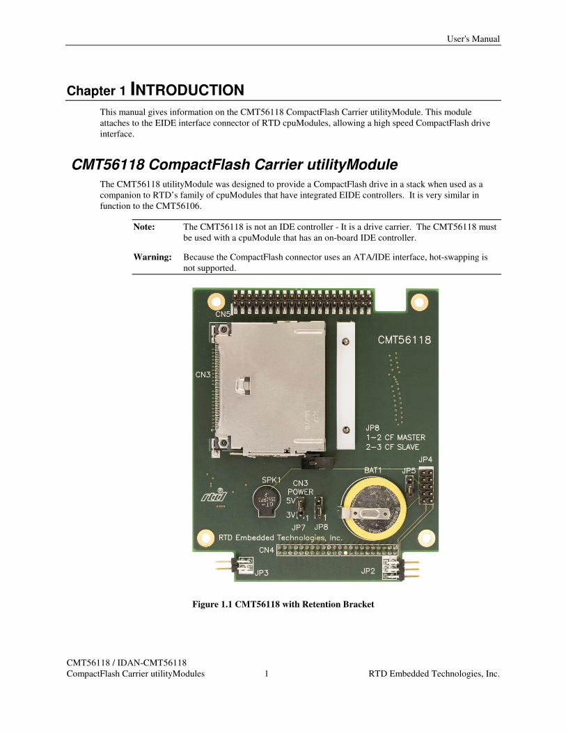
Chapter 1 INTRODUCTION This manual gives information on the CMT56118 CompactFlash Carrier utilityModule. This module
attaches to the EIDE interface connector of RTD cpuModules, allowing a high speed CompactFlash drive
interface.
CMT56118 CompactFlash Carrier utilityModule The CMT56118 utilityModule was designed to provide a CompactFlash drive in a stack when used as a
companion to RTD’s family of cpuModules that have integrated EIDE controllers. It is very similar in
function to the CMT56106.
Note: The CMT56118 is not an IDE controller - It is a drive carrier. The CMT56118 must
be used with a cpuModule that has an on-board IDE controller.
Warning: Because the CompactFlash connector uses an ATA/IDE interface, hot-swapping is
not supported.
Figure 1.1 CMT56118 with Retention Bracket
Features
CMT56118 / IDAN-CMT56118
CompactFlash Carrier utilityModules 2 RTD Embedded Technologies, Inc.
Features The following are major features of the CMT56118 utilityModule.
• Provides a drive interface up to UDMA Mode 2 (Ultra ATA/33) if supported by the
cpuModule
• A standard +3.3V or +5V CompactFlash drive can be mounted directly onto the module
• An optional retention bracket provides a mechanism to prevent unwanted removal of the
CompactFlash device
• A 0.1” 40-pin connector is provided to connect to a second drive, i.e. a CD-ROM drive.
• A stack-through connector is provided to allow for the combination of multiple boards from
the CMT56118, CMT36106, and CMT56106 utilityModule families in one system.
Connectors Connectors provided are:
• CN3: CompactFlash drive connector
• CN4: EIDE stack-through connector
• CN5: EIDE cable connector
Recommended Cables A 40-conductor EIDE cable can be used to connect an external drive (hard drive or CD-ROM drive) to
connector CN5 on the CMT56118.
General Specifications
The following operating conditions do not apply to the CompactFlash drive and may be limited by the IDE
controller of the cpuModule
• Operating temperature: -40 to +85ºC
• Relative humidity: 0 - 95%, non-condensing
• Storage temperature: -55 to +125ºC

User’s Manual
CMT56118 / IDAN-CMT56118
CompactFlash Carrier utilityModules 3 RTD Embedded Technologies, Inc.
Chapter 2 INSTALLING THE UTILITYMODULE
Since the utilityModule uses an EIDE stack-through bus, it must be stacked directly above the cpuModule.
Recommended Procedure We recommend you follow the procedure below to ensure that stacking of the modules does not damage
connectors or electronics.
• Turn off power to the PC/104-Plus or PCI-104 system or stack.
• Select and install standoffs to properly position the utilityModule on the PC/104-Plus or PCI-
104 stack.
• Touch a grounded metal part of the stack to discharge any buildup of static electricity.
• Remove the utilityModule from its anti-static bag.
• Verify the jumper settings of the utilityModule.
• Hold the utilityModule by its edges and orient it so the bus connector pins line up with the
matching connector on the stack.
• Gently and evenly press the utilityModule onto the stack.
CAUTION: Do not force the module onto the stack! Wiggling the module or applying too
much force may damage it. If the module does not readily press into place, remove it,
check for bent pins or out-of-place keying pins, and try again.
Connector and Jumper Locations
CMT56118 / IDAN-CMT56118
CompactFlash Carrier utilityModules 4 RTD Embedded Technologies, Inc.
Chapter 3 CONNECTING THE UTILITYMODULE The following sections describe the connectors and jumpers of the utilityModule.
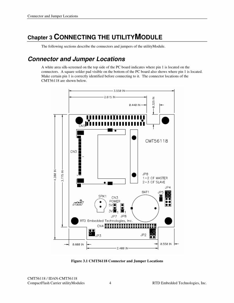
Connector and Jumper Locations A white area silk-screened on the top side of the PC board indicates where pin 1 is located on the
connectors. A square solder pad visible on the bottom of the PC board also shows where pin 1 is located.
Make certain pin 1 is correctly identified before connecting to it. The connector locations of the
CMT56118 are shown below.
Figure 3.1 CMT56118 Connector and Jumper Locations
User’s Manual
CMT56118 / IDAN-CMT56118
CompactFlash Carrier utilityModules 5 RTD Embedded Technologies, Inc.
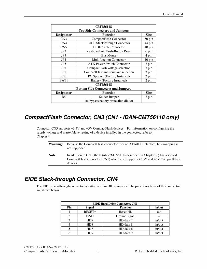
CMT56118
Top Side Connectors and Jumpers
Designator Function Size
CN3 CompactFlash Connector 50 pin
CN4 EIDE Stack-through Connector 44 pin
CN5 EIDE Cable Connector 40 pin
JP2 Keyboard and Push-Button Reset 6 pin
JP3 Bus Mouse 4 pin
JP4 Multifunction Connector 10 pin
JP5 ATX Power Switch Connector 2 pin
JP7 CompactFlash voltage selection 3 pin
JP8 CompactFlash master/slave selection 3 pin
SPK1 PC Speaker (Factory Installed) 2 pin
BAT1 Battery (Factory Installed) 2 pin
CMT56118
Bottom Side Connectors and Jumpers
Designator Function Size
B5 Solder Jumper
(to bypass battery protection diode)
2 pin
CompactFlash Connector, CN3 (CN1 - IDAN-CMT56118 only)
Connector CN3 supports +3.3V and +5V CompactFlash devices. For information on configuring the
supply voltage and master/slave setting of a device installed in the connector, refer to
Chapter 4 .
Warning: Because the CompactFlash connector uses an ATA/IDE interface, hot-swapping is
not supported.
Note: In addition to CN3, the IDAN-CMT56118 (described in Chapter 5 ) has a second
CompactFlash connector (CN1) which also supports +3.3V and +5V CompactFlash
devices.
EIDE Stack-through Connector, CN4 The EIDE stack-through connector is a 44-pin 2mm DIL connector. The pin connections of this connector
are shown below.
EIDE Hard Drive Connector, CN3
Pin Signal Function in/out
1 RESET* Reset HD out
2 GND Ground signal --
3 HD7 HD data 7 in/out
4 HD8 HD data 8 in/out
5 HD6 HD data 6 in/out
6 HD9 HD data 9 in/out
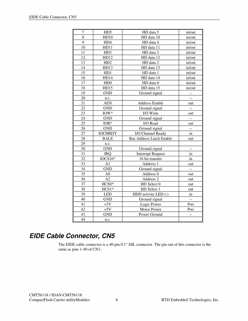
EIDE Cable Connector, CN5
CMT56118 / IDAN-CMT56118
CompactFlash Carrier utilityModules 6 RTD Embedded Technologies, Inc.
7 HD5 HD data 5 in/out
8 HD10 HD data 10 in/out
9 HD4 HD data 4 in/out
10 HD11 HD data 11 in/out
11 HD3 HD data 3 in/out
12 HD12 HD data 12 in/out
13 HD2 HD data 2 in/out
14 HD13 HD data 13 in/out
15 HD1 HD data 1 in/out
16 HD14 HD data 14 in/out
17 HD0 HD data 0 in/out
18 HD15 HD data 15 in/out
19 GND Ground signal --
20 n.c. --
21 AEN Address Enable out
22 GND Ground signal --
23 IOW* I/O Write out
24 GND Ground signal --
25 IOR* I/O Read out
26 GND Ground signal --
27 IOCHRDY I/O Channel Ready in
28 BALE Bus Address Latch Enable out
29 n.c.
30 GND Ground signal --
31 IRQ Interrupt Request in
32 IOCS16* 16 bit transfer in
33 A1 Address 1 out
34 GND Ground signal --
35 A0 Address 0 out
36 A2 Address 2 out
37 HCS0* HD Select 0 out
38 HCS1* HD Select 1 out
39 LED HDD activity LED (-) in
40 GND Ground signal --
41 +5V Logic Power Pwr
42 +5V Motor Power Pwr
43 GND Power Ground --
44 n.c.
EIDE Cable Connector, CN5 The EIDE cable connector is a 40-pin 0.1" DIL connector. The pin out of this connector is the
same as pins 1-40 of CN3.
User’s Manual
CMT56118 / IDAN-CMT56118
CompactFlash Carrier utilityModules 7 RTD Embedded Technologies, Inc.
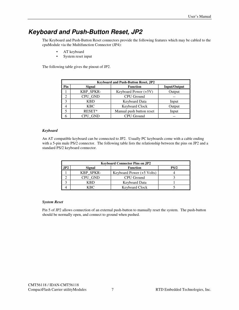
Keyboard and Push-Button Reset, JP2 The Keyboard and Push-Button Reset connectors provide the following features which may be cabled to the
cpuModule via the Multifunction Connector (JP4):
• AT keyboard
• System reset input
The following table gives the pinout of JP2.
Keyboard and Push-Button Reset, JP2
Pin Signal Function Input/Output
1 KBP_SPKR- Keyboard Power (+5V) Output
2 CPU_GND CPU Ground --
3 KBD Keyboard Data Input
4 KBC Keyboard Clock Output
5 RESET* Manual push button reset Input
6 CPU_GND CPU Ground --
Keyboard
An AT compatible keyboard can be connected to JP2. Usually PC keyboards come with a cable ending
with a 5-pin male PS/2 connector. The following table lists the relationship between the pins on JP2 and a
standard PS/2 keyboard connector.
Keyboard Connector Pins on JP2
JP2 Signal Function PS/2
1 KBP_SPKR- Keyboard Power (+5 Volts) 4
2 CPU_GND CPU Ground 3
3 KBD Keyboard Data 1
4 KBC Keyboard Clock 5
System Reset
Pin 5 of JP2 allows connection of an external push-button to manually reset the system. The push-button
should be normally open, and connect to ground when pushed.
Bus Mouse, JP3
CMT56118 / IDAN-CMT56118
CompactFlash Carrier utilityModules 8 RTD Embedded Technologies, Inc.
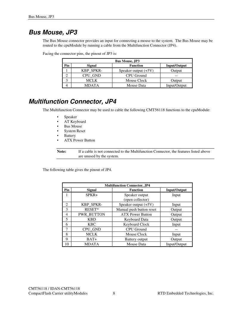
Bus Mouse, JP3 The Bus Mouse connector provides an input for connecting a mouse to the system. The Bus Mouse may be
routed to the cpuModule by running a cable from the Multifunction Connector (JP4).
Facing the connector pins, the pinout of JP3 is:
Bus Mouse, JP3
Pin Signal Function Input/Output
1 KBP_SPKR- Speaker output (+5V) Output
2 CPU_GND CPU Ground --
3 MCLK Mouse Clock Output
4 MDATA Mouse Data Input/Output
Multifunction Connector, JP4 The Multifunction Connector may be used to cable the following CMT56118 functions to the cpuModule:
• Speaker
• AT Keyboard
• Bus Mouse
• System Reset
• Battery
• ATX Power Button
Note: If a cable is not connected to the Multifunction Connector, the features listed above
are unused by the system.
The following table gives the pinout of JP4.
Multifunction Connector, JP4
Pin Signal Function Input/Output
1 SPKR+ Speaker output
(open collector)
Input
2 KBP_SPKR- Speaker output (+5V) Input
3 RESET* Manual push button reset Output
4 PWR_BUTTON ATX Power Button Output
5 KBD Keyboard Data Output
6 KBC Keyboard Clock Input
7 CPU_GND CPU Ground --
8 MCLK Mouse Clock Input
9 BAT+ Battery output Output
10 MDATA Mouse Data Input/Output
User’s Manual
CMT56118 / IDAN-CMT56118
CompactFlash Carrier utilityModules 9 RTD Embedded Technologies, Inc.
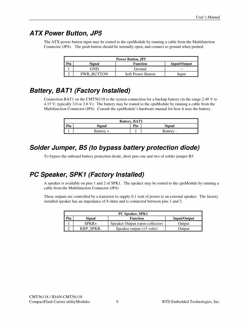
ATX Power Button, JP5 The ATX power button input may be routed to the cpuModule by running a cable from the Multifunction
Connector (JP4). The push-button should be normally open, and connect to ground when pushed.
Power Button, JP5
Pin Signal Function Input/Output
1 GND Ground --
2 PWR_BUTTON Soft Power Button Input
Battery, BAT1 (Factory Installed) Connection BAT1 on the CMT56118 is the system connection for a backup battery (in the range 2.40 V to
4.15 V; typically 3.0 or 3.6 V). The battery may be routed to the cpuModule by running a cable from the
Multifunction Connector (JP4). Consult the cpuModule’s hardware manual for how it uses the battery.
Battery, BAT1
Pin Signal Pin Signal
1 Battery + 2 Battery -
Solder Jumper, B5 (to bypass battery protection diode) To bypass the onboard battery protection diode, short pins one and two of solder jumper B5.
PC Speaker, SPK1 (Factory Installed) A speaker is available on pins 1 and 2 of SPK1. The speaker may be routed to the cpuModule by running a
cable from the Multifunction Connector (JP4)
These outputs are controlled by a transistor to supply 0.1 watt of power to an external speaker. The factory
installed speaker has an impedance of 8 ohms and is connected between pins 1 and 2.
PC Speaker, SPK1
Pin Signal Function Input/Output
1 SPKR+ Speaker Output (open collector) Output
2 KBP_SPKR- Speaker output (+5 volts) Output

CF Voltage Select Jumper, JP7 (JP9 – IDAN-CMT56118 only)
CMT56118 / IDAN-CMT56118
CompactFlash Carrier utilityModules 10 RTD Embedded Technologies, Inc.
Chapter 4 CONFIGURING THE UTILITYMODULE The following sections contain information on configuring the utilityModule.
Important: The EIDE bus connection on the CMT56118 which provides the electrical
connections to the CompactFlash connector (CN3) and the EIDE cable connector
(CN5) connects to the CPU’s IDE controller via the EIDE stack-through connector
(CN4). While this IDE channel connection supports multiple boards, up to two
storage devices (e.g., CompactFlash cards, 2.5” disk drives, IDE drives, CD-ROM
drives, ATA/IDE Disk Chip) are permitted throughout this electrical bus.
To prevent a conflict with a device already on the bus, it is important to know the
number of devices already residing on the bus, as well as their master/slave
configuration.
CF Voltage Select Jumper, JP7 (JP9 – IDAN-CMT56118 only) Jumper JP7 is a 3-pin jumper used to select the supply voltage for the CompactFlash device residing in
connector CN3.
To configure the operating voltage for 3.3V, set JP7 to close pins 1-2. To configure the operating voltage
for 5V, set JP7 to close pins 2-3.
Note: The IDAN-CMT56118 (described in Chapter 5 ) has a second jumper (JP9) to
configure the CF supply voltage of a second CompactFlash connector (CN1). The
jumper behaves the same as JP7, with the same pinout.
Master/Slave Selection Jumper, JP8 Jumper JP7 is a 3-pin jumper used to configure the CompactFlash device in connector CN3 such that it does
not conflict with another device connected to the system’s EIDE stack-through connector. The bus should
have only one master and one slave device.
To set the CompactFlash card as the master, close pins 1-2 of JP8. To set the CompactFlash card as the
slave, close pins 2-3.
Note: The IDAN-CMT56118 (described in Chapter 5 ) is designed such that when one of
the CF sockets is configured as master, the other is configured as slave. JP8 may be
set as follows:
Close pins 1-2: CN1 master, CN3 slave
Close pins 2-3: CN3 master, CN1 slave
User’s Manual
CMT56118 / IDAN-CMT56118
CompactFlash Carrier utilityModules 11 RTD Embedded Technologies, Inc.
Connecting External IDE Devices External EIDE drives such as additional hard drive or CD-ROM drive can be connected to CN5 of the
CMT56118 with an IDE cable. Only 40-conductor IDE cables are supported, which permit transfer speeds
of up to UDMA Mode 2 (Ultra ATA/33).
When connecting an external drive to the CMT56118, the device’s master/slave jumper must be configured
such that it does not conflict with the master/slave setting of any other device connected to the system’s
EIDE stack-through connector (for example, the CompactFlash connector, when a CF card is present in the
socket).
Connector and Jumper Locations
CMT56118 / IDAN-CMT56118
CompactFlash Carrier utilityModules 12 RTD Embedded Technologies, Inc.
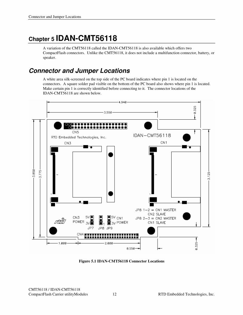
Chapter 5 IDAN-CMT56118 A variation of the CMT56118 called the IDAN-CMT56118 is also available which offers two
CompactFlash connectors. Unlike the CMT56118, it does not include a multifunction connector, battery, or
speaker.
Connector and Jumper Locations A white area silk-screened on the top side of the PC board indicates where pin 1 is located on the
connectors. A square solder pad visible on the bottom of the PC board also shows where pin 1 is located.
Make certain pin 1 is correctly identified before connecting to it. The connector locations of the
IDAN-CMT56118 are shown below.
Figure 5.1 IDAN-CMT56118 Connector Locations
User’s Manual
CMT56118 / IDAN-CMT56118
CompactFlash Carrier utilityModules 13 RTD Embedded Technologies, Inc.
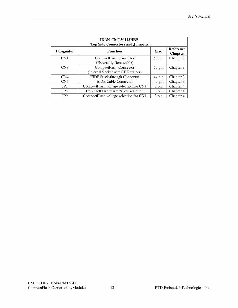
IDAN-CMT56118HRS
Top Side Connectors and Jumpers
Designator Function Size Reference
Chapter
CN1 CompactFlash Connector
(Externally Removable)
50 pin Chapter 3
CN3 CompactFlash Connector
(Internal Socket with CF Retainer)
50 pin Chapter 3
CN4 EIDE Stack-through Connector 44 pin Chapter 3
CN5 EIDE Cable Connector 40 pin Chapter 3
JP7 CompactFlash voltage selection for CN3 3 pin Chapter 4
JP8 CompactFlash master/slave selection 3 pin Chapter 4
JP9 CompactFlash voltage selection for CN1 3 pin Chapter 4
Connector and Jumper Locations
CMT56118 / IDAN-CMT56118
CompactFlash Carrier utilityModules 14 RTD Embedded Technologies, Inc.
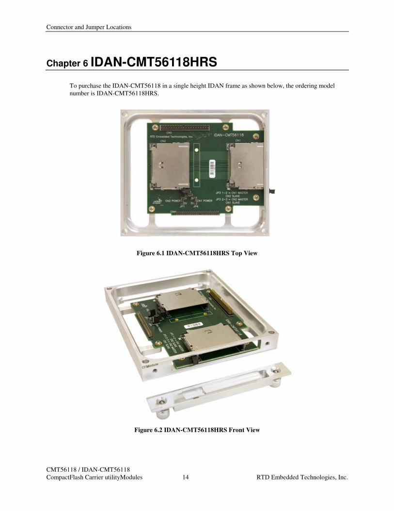
Chapter 6 IDAN-CMT56118HRS
To purchase the IDAN-CMT56118 in a single height IDAN frame as shown below, the ordering model
number is IDAN-CMT56118HRS.
Figure 6.1 IDAN-CMT56118HRS Top View
Figure 6.2 IDAN-CMT56118HRS Front View
User’s Manual
CMT56118 / IDAN-CMT56118
CompactFlash Carrier utilityModules 15 RTD Embedded Technologies, Inc.
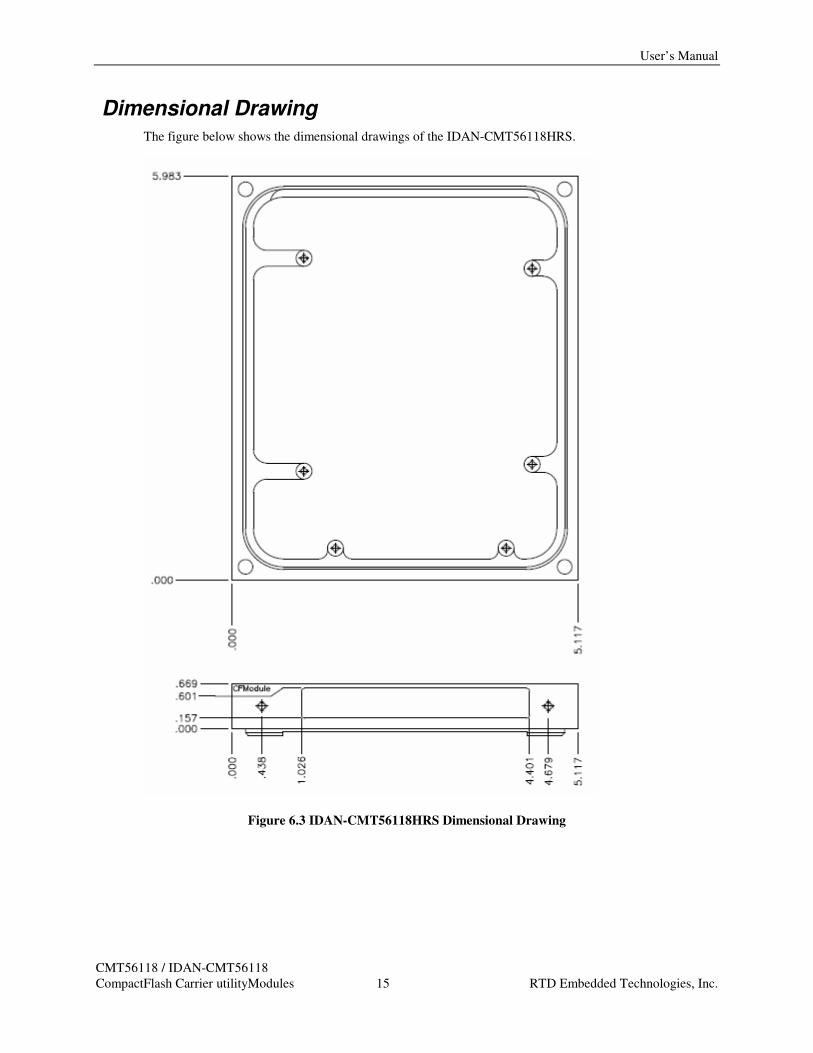
Dimensional Drawing The figure below shows the dimensional drawings of the IDAN-CMT56118HRS.
Figure 6.3 IDAN-CMT56118HRS Dimensional Drawing
Dimensional Drawing
CMT56118 / IDAN-CMT56118
CompactFlash Carrier utilityModules 16 RTD Embedded Technologies, Inc.
Chapter 7 GETTING TECHNICAL SUPPORT
For help with this product, or any other product made by RTD, you can contact RTD Embedded
Technologies via the following methods:
• Phone: +1-814-234-8087
• E-Mail: [email protected]
Be sure to check the RTD web site (http://www.rtd.com) frequently for product updates, including newer
versions of the board manual and application software.

User’s Manual
CMT56118 / IDAN-CMT56118
CompactFlash Carrier utilityModules 17 RTD Embedded Technologies, Inc.
LIMITED WARRANTY RTD Embedded Technologies, Inc. warrants the hardware and software products it manufactures and
produces to be free from defects in materials and workmanship for one year following the date of shipment
from RTD Embedded Technologies, INC. This warranty is limited to the original purchaser of product and
is not transferable.
During the one year warranty period, RTD Embedded Technologies will repair or replace, at its option, any
defective products or parts at no additional charge, provided that the product is returned, shipping prepaid,
to RTD Embedded Technologies. All replaced parts and products become the property of RTD Embedded
Technologies. Before returning any product for repair, customers are required to contact the factory for an
RMA number.
THIS LIMITED WARRANTY DOES NOT EXTEND TO ANY PRODUCTS WHICH HAVE BEEN
DAMAGED AS A RESULT OF ACCIDENT, MISUSE, ABUSE (such as: use of incorrect input voltages,
improper or insufficient ventilation, failure to follow the operating instructions that are provided by RTD
Embedded Technologies, "acts of God" or other contingencies beyond the control of RTD Embedded
Technologies), OR AS A RESULT OF SERVICE OR MODIFICATION BY ANYONE OTHER THAN
RTD Embedded Technologies. EXCEPT AS EXPRESSLY SET FORTH ABOVE, NO OTHER
WARRANTIES ARE EXPRESSED OR IMPLIED, INCLUDING, BUT NOT LIMITED TO, ANY
IMPLIED WARRANTIES OF MERCHANTABILITY AND FITNESS FOR A PARTICULAR
PURPOSE, AND RTD Embedded Technologies EXPRESSLY DISCLAIMS ALL WARRANTIES NOT
STATED HEREIN. ALL IMPLIED WARRANTIES, INCLUDING IMPLIED WARRANTIES FOR
MECHANTABILITY AND FITNESS FOR A PARTICULAR PURPOSE, ARE LIMITED TO THE
DURATION OF THIS WARRANTY. IN THE EVENT THE PRODUCT IS NOT FREE FROM
DEFECTS AS WARRANTED ABOVE, THE PURCHASER'S SOLE REMEDY SHALL BE REPAIR OR
REPLACEMENT AS PROVIDED ABOVE. UNDER NO CIRCUMSTANCES WILL RTD Embedded
Technologies BE LIABLE TO THE PURCHASER OR ANY USER FOR ANY DAMAGES,
INCLUDING ANY INCIDENTAL OR CONSEQUENTIAL DAMAGES, EXPENSES, LOST PROFITS,
LOST SAVINGS, OR OTHER DAMAGES ARISING OUT OF THE USE OR INABILITY TO USE THE
PRODUCT.
SOME STATES DO NOT ALLOW THE EXCLUSION OR LIMITATION OF INCIDENTAL OR
CONSEQUENTIAL DAMAGES FOR CONSUMER PRODUCTS, AND SOME STATES DO NOT
ALLOW LIMITATIONS ON HOW LONG AN IMPLIED WARRANTY LASTS, SO THE ABOVE
LIMITATIONS OR EXCLUSIONS MAY NOT APPLY TO YOU.
THIS WARRANTY GIVES YOU SPECIFIC LEGAL RIGHTS, AND YOU MAY ALSO HAVE OTHER
RIGHTS WHICH VARY FROM STATE TO STATE.

Dimensional Drawing
CMT56118 / IDAN-CMT56118
CompactFlash Carrier utilityModules 18 RTD Embedded Technologies, Inc.
RTD Embedded Technologies, Inc.
103 Innovation Blvd.
State College PA 16803-0906
USA
Our website: www.rtd.com
Techsupport: [email protected]
(814) 234-4626