Embed Size (px)
Citation preview
CNC Gear ShapingDr. G. Sulzer
Liebherr Macbine~ToolsGerman.y
THE COOLANT CANNOT GETTO THE TOOL CUTTING - EDGE
..ACTUALCUTTINGCONTACTLENGTHOF TOOl.
Fig. 1
Inuoduction
New Developments in Tools,and Machines
Two major proeessesare used for cut-ting gears, hobbing and shaping. Becauseof it's universal application and it's highperformance, hobbing is generally pre-ferred. A hobbing machine is universalenough to produce worms, worm gears,spur and helical gears, By using Multi-start hobs, the productivity of themachine can be mcreased considerably.
Normally shaping is only used whenhobbing is impossible due to the form ofthe parts to be cut, Le, internal gears andduster gears with shoulders. Multistart'cutters cannot be used. Nevertheless, the
AlITHOR:
DR. G. 5UUERis Manager of .Research &Development at UEBHERR in West Gemurny,He earned his doctorate at the University ofAachen .in Aachen, Gennany where he hasworked in the role of Marzager ResearchDevelopment for twelve years. He has beeninstrumental in the development of theLiebherr CNC machines.
16 Gea-r Iechnology
technological disadvantages can be re-duced by advanced machine design andbetter cutter materials.
Too[sSintered and tin coated high speed
steels are generally established as cuttermaterials. Sintered high speed steel isparticularly su.ited to shaping because ofits durability when cutting at hightemperatures, which arises more in shap-ing than in hobbing. Depending on thewidth of gear, a longer cut occurs and theaccess for coolant is limited during cut-ting.(Fig. 1 and Fig. 2)
The additional tin coating improveswear resistance on the tooth flanks. Thetime ·01 contact between hob andworkpiece isgeneralJy shorter than inshaping, and the access for coolant ismuch better.
To a limited extent, carbide cutters arealso used but in the field of machininghardened gears only. Similar to skivehobbing, cutting speeds are increased byabout 30% compared with softmachining.
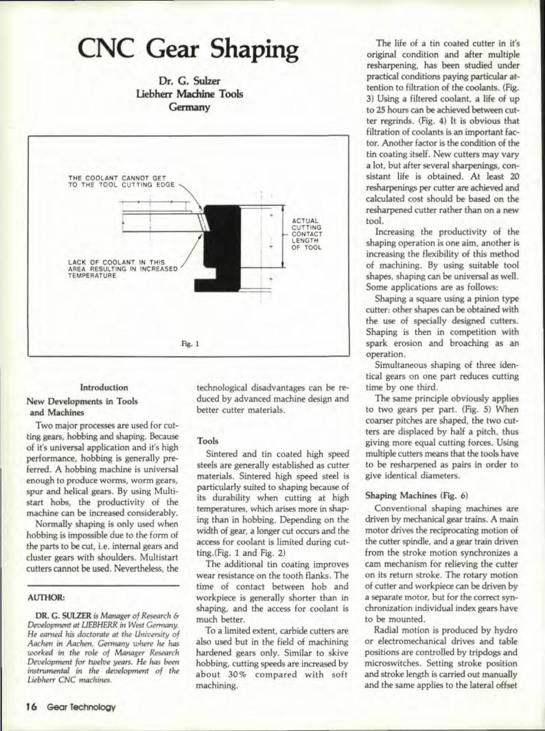
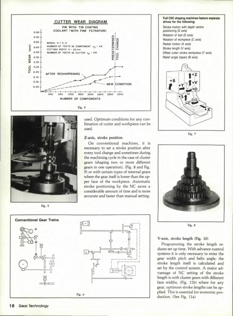
The life of a tin coated cutter in it'soriginal condition and after mu1tipl.eresharpening, has been studied underpractical conditions paying particular at-tention to filtration of the coolants. (Fig.3) Using a filtered ,coolant, a .Iife 'of upto 2S hours can be achieved between cut-ter regrinds .. (Fig .. 4) ]t is obvious thatfiltration of coolants is an important fac-tor. Another factor is the condition of 'thetin coating itself ..New cutters may varya lot, but after several sharpenings, con-sistant life is obtained. At [east 20.resharpenings per cutter are achieved andcalculated cost should be based on Itheresharpened cutter rather than on a newtoo].
Increasing the productivity of thshaping operation is one aim, another isincreasing the flexibillry of this methodof machining. By using suitable toolshapes, shaping can be universal as well,Some applications are as follows:
Shaping a square using a pinion typecutter: other shapes can be obtained withthe use of speciaUy designed cutters,Shaping is then in competition withspark erosion and broaching as an.operation.
Simultaneous shaping of three iden-tical gears on one part reduces cuttingtime by one third.
The same principle obviously appliesto two gears per pa:rt. (Fig. 5) Whencoarser pitches are shaped, the two cut-ters are displaced by half a. pitch, thusgiving more equal cutting forces. Usingmultiple cutters means that 'the tools haveto be resharpened as pairs in order togive identical diameters.
Shaping Machines (fig. 6)Conventi.onal shaping machines are
driven by mechanical gear trains. A main.motor drives the reciprocating motion ofthe cutter spindle, and a gear train drivenfrom the stroke motion synchronizes acam mechanism for relieving the cutteron its return stroke. The rotary motionof cutter and workpiece can be driven bya separate motor, but for the correct syn-chronization individuaJ index gears haveto be mounted.
Radial motion is produced by hydrooreleetromecharucal drives and tablepositions are controlled bytripdogs andmkroswitches. Setting stroke positionand stroke length is carried out manuallyand the same applies to the lateral offset
UNDISTURBEDCOOLANT SUPPLY CONTACT LENGTH OF TOOL
Fig. 2
0.60
0.55
0.50
E 0.45E
O.~·O
0::0.35<1:.
WI~ 0.30oJ' 0.2500
0.20~0.15
0'.10
0.05
CUTTER WEAR IDIIAGRAMiPM W'Ifll-1 TIN COAfliNG
COOLANT IWITIHOUr FILTRATION I
/" --7---Y END OF TEST
/ *j/' AFTER RESHARPENING
NEW CONDITION --/
r~"iI
jMODUL m' O.~NUMBER OF TEETH IN COMPONENT z2 • ~4
CUTT!NG W!DTH b' 25 mmNUMBER OF T·EETH IN CUTTER '0 • 135
400 BOO 1200 1600 2000 2400 2800 3200
NUMBER OF C'OMPONENTS
Fig. 3
between cunera:nd workpiece forpreventing interference on cutter returnstroke ..
Linear path NC shaping machines areusual!ly fitted with separate drives for thefollowing:
tween cutter and work. Adjustment ofstroke position and stroke length as wellas cutter to worktable offset are adjustedmanually as on the conventionalmachine.
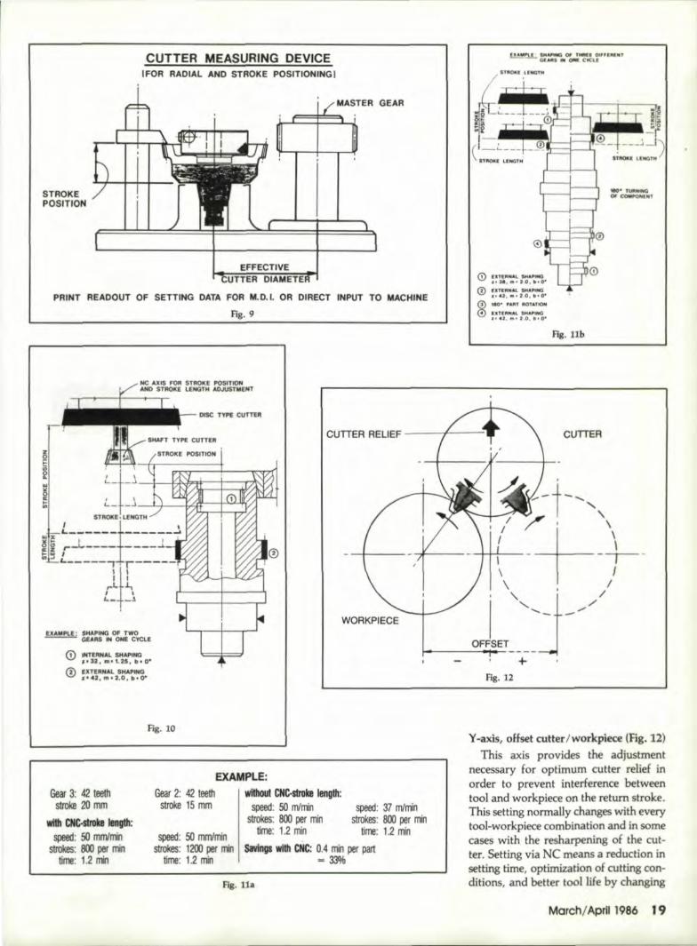
Full. CNC shaping machines featureseparate drives for the following: (Fig. 7)
Stroke motionRotation of tool and workpieceRadial motion (X axis)Stroke position (2 axis)
Stroke motion with depth center posi-honing (5 axis)
Rotation of tool (0 axis)Rotation of workpiece (C axis)Radial motion (X axis)Stroke position (2 axis)Stroke length (V axis)
With this type of machine, it is stillInecessary to use index change gears inorder to achieve the synchronization be-
Offset cutter stroke workpiece (Y axis)Relief angle (taper) (B axis)
Through using NC on all axes, a CNCshaping machine gives the followingadvantages:
S Axis, stroke motion with dead centerpositioning
Cutter speed (number of strokes perminute) is programmable for any com-bination of infeeds,. roughing, finishingor dwell operation. Therefore shortestcutting times are achieved withoutoverloading the cutter. The dead centerpositioning feature assures safety whencutting internal gears (clearance betweenthe cutter and workpiece during radialmotions) and enhances stroke position-ing in the set up mode.
Die-axis, rotation 'of Itoo~and workpleeeIn normal applications, the axes D and
C are performing a synchronizing motionbetween cutter and workpiece and con-trolling the generating feed programs.Mounting of index change gears is ob-solete, feeds are programmable anddependent on the geometry andmachinability of the parts to be cut Forbalanced wear distribution on the Ranksof the cutter, the direction of rotation canbe changed automatically.
For special applications, each of theaxes can be moved individually, such asfor single index shaping of splines orkeyways or angular positioning of thecutter to the workpiece. A combinationof shaping by the generating method andsubsequent single indexing (with a secondcutter) in one operation is possible. Thusthe range of applications is considerablyextended.
X-axis, radial motion.Positional accuracy of the NC is ap-
proximately 0.005 mm. This means ,thatsafety clearances can be reduced to theoutside diameter to be cut, and rapidtraverses dose to the outside diameter ·ofthe workpiece can be used. Tool offsets(difference in diameter) of the cutter tobe used can be measured outside of themachine and an offset entered into thecontrol while the machine is in operation.A combination of rotary and radial feedsallows any process such as pure radial in-feed and extreme spiral inJeedJng to be
Marchi April 1986 17
CUTTER: WEAR !OIA.GRAMIPM! WITHilN ,COATING
C'OOLANT I WITH FINE FII.TRATION Ii0'.60
0.55
0.50
E 0'.• 5,.§
0.• 0II:C 0.35,W~ 0.30..J 0'.25·0o 0.20I-
0.15,
0.10
0.05,
CUTTING WIDTHI ,b • 25 mm
MODUl III' 0.,4
NUMBER OF T'EETH IN COMPONENT '2 • 4 ..
NUMBER OF TEETH IN CUTlER '0 • "35
AFTER RESHARPENING, .-..~--..~ .
.... --- __ -c".~ NEW ICONDITION.-> ..,-.---
~--::::;..~--
400 800 1200 1800' 2000 2400 2800 3200
NUMBEII 'OF COMPONENTS
Fig. 5
Fig. II
used. Optimum conditions for any con-bination of cutter and workpiece can beused.
Z-axis, stroke positionOn conventional machines, it is
necessary to set a stroke position afterevery tool change and sometimes duringthe machining cycle in the case of clustergears (shaping two or more d:ifferentgears in one operation), (Fig. 8 and Fig.9) or with certain types of internal. gearswhere the gear itself i.slower than the up-per face of the workpiece. Automaticstroke positioning by the NCsaves aconsiderable amount of time and is moreaccurate and faster than manual setting.
Conventional 'Gear Trains
Fig. 6
1,8 Gear Jechno'iogy
IFulllCNC shaping machines, feature S8pt1rate,drives, tor Ihe,foUowing:
Stroke motion with depth centrepositioning (S axis)Rotation of tool (0 axis)Rolation 01 workpiece (Cax.is)Radial motion ex axis)Stroke length 01 axis)Offset cutter stroke workpiece (Y axjs)Flellef angle' (taper) (8 axis)
Fig .. 7
Fig. 8
V-.axis, stroke ~ength (fig. 10)Programming the stroke length re-
duces set up time. With advance controlsystems it is only necessary to enter thegear width pitch and helix angIe; thestroke length itself is calculated andset by the control system. A major ad-vantage of NC setting of the strokelength is with duster gears with differentface widths, (Fig. lIb) where for anygear, optimum stroke lengths can be ap-plied. This is essential for economic pro-duction. (See Hg. 11a)
STIR.OKEPOSITION
CUTTER MEASUIRIN'G, DEVIICEIFOR RADI:AL AflD STROke POSfmlONING,1
GEAR
PRINT IREADOIJT OF SETTING DATA FOR M.D.I. 'OR IDIRECT INPUT T'O MACHINE
Fig. 9
EIU.~PLE: ,SH;lPII!(!, OFTWQ--- GEARS 'IN OI!E ',CYCLE
o INTERNAL Sl'fAPING:.~32', 1m, II 1.25, b,.O·
® IItTIR~AL SKAPItlGJi!!,4-,J .. lml.2.0i bilO·
~ IUiIMWQ QlI1 ,tN. _':I"-I"N1'G;I:,UI .. OM! C¥QI
n~E U:JiIC1N
~ii 'fiJllUiltHGor COMPOMIIT
(9 IEI:niiiNAl 11tIA!Ji1llilO,I' 3'.1II~ 1 D,"'O'·
® IITEPINAL. 'NJ.I'ING,1.41.,.t l!.1, !l10"o 11D,;; ,.,.JIIT !ll:Of~liOf!1
® EJ'l'fJiiJilAL 'M.I."INoD,to 42. ftIo" 2.0, 11'.0-
Fig. lib
WORKPIeCE
CUTrER;
Gear 3: 42' teethstroke 20 mm
with CNc.Sb'OkI, IengUl:speed: 50 mJlillTilli
strokes: 800 per nWllime: 1.2 rrin
EXA_MPLE:Gear 2: 42 teeth withoU1'CNC-sLrol!e length:
stroke lS mm speed: SO mlmin speed: 37 mlminstrokes: 800 per min strokes: 800 ,per min
UJne: 11.2mil time: 1.2 minsavings wHb CNC: 11.4 min per ;part
...33%speed: 51! mmlmin
strokes: 1200 lper miJ1Iirm: 1.2 min
Flg.lla
),.,axis, offset cutler/workpiece (F~g"12)This axis provides the adjustment
necessary for optimum, cutter r'elief tnorder to prevent interf,erence betweentool and workpiece on the return stroke ..This setting normalJy changes with ,everytool-workpiece combination and in somecases with the resharpening of the cut-ter ..Setting via NC means a reduction insetting time, optimization of cutting con-ditions, and better tool life by changing
Mmchl April 1986 19
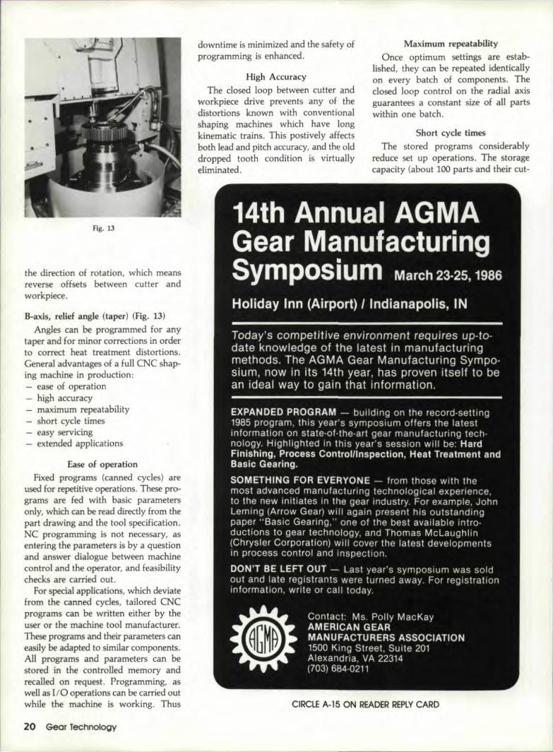
Fig. 13
the direction of rotation, which meansreverse offsets. between cutter andworkpiece.
8~a.xis,relief angle (taper) (Fig. 13)Angles can be programmed tor any
'taper and for minor corrections in orderto correct heat treatment distortions.General advantages of a full CNC shap-ing machine in production:
ease of operationhigh accuracymaximum repeatabilityshort cycle timeseasy servicingextended applications
Ease of operationFixed programs (canned cycles) are
used for repetitive operations ..These pro-grams are fed with basic parametersonly, which can be read directly hom thepart drawing and the tool specification.NC programming is not necessary, asentering the parameters is by a questionand answer dialogue between machinecontrol and the operator, and feasibilitychecks are carried out.
For special applications, which deviatefrom the canned cycles, tailored CNCprograms can be written either by theuser or the machine tool manufacturer.These programs and their parameters caneasily be adapted to similar components.All programs and parameters can bestored in the controlled memory andrecalled on request. Programming, aswell as [f0 operations can be carried outwhile the machine is working. Thus
20 Gear Technology
downtime is minimized and the safety ofprogramming is enhanced.
Maxim.um n!(reatabilityOnce optimum settlngsare estab-
lished, they can be repeated identicallyon every batch of components. Thedosed loop control on the radial axisguarantees a constant size of all partswithin one batch.
High AccuracyThe dosed loop between cutter and
workpiece drive prevents any of thedistortions known with conventionalshaping machines which have longkinematic trains. This postively affectsboth lead and pitch accuracy, and the olddropped tooth condition is virtuallyeliminated,
Short cycle timesThe stored programs considerably
reduce set up operations. The storagecapacity (about 100 parts and theircut-
CIRCLE A·15 .oN READER REPLYCARD
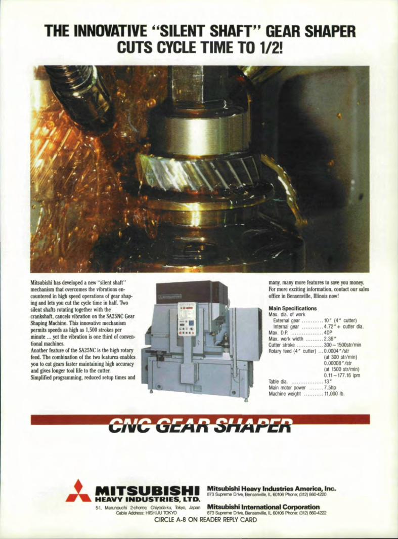
'TIH'E IINNOVATIME ",SILENT SHAFT" GEAIRSHAPER'C'UITS CYC:LETIME TO 1/2!
Milsubisilil has d.eveloped a new "silent' baft"medJanism Ibalmrromes, the vibrations en-countered in bigh speed operations of gear sbap-ing and lets you eut the ,cyde time in half. fwD'silent shafts rotating logelberwith the,cranksllaft, cancels vibration on the SA2SNC GearShapLng Macbine ..This inn.ovative meehanismpermits 'peed~ as IUgh as ),500 stro""es perminute ... yet the vibration is one third 'of COO'i'eD-tional. machines.Another feature of Ihe SA25NC is the nigh .rotaryfeed. The combination of tbe two fealufes 'enablesyou to. cut gem faster maintaining higll ,aocuracyand gives longer too] life to the cutter.Simplified programming. reduced ,setup times and
DlLny. many more features to save you money.for more exciting information, contacl OUJ salesoffice in BensellVHle, Illinois now!'
IMain SpeclflcaUonsMax. dla. of work
External gear 10' (.:I' cutter)Internal gear .4.72· + cuner :ola.
Max. D.P 4DPMax. work wldth 2.36·Cutter stroke' 300 -1500str/minIRotary feed [4" cutter) 0.0004· Islr
(al 300 strfmln)0.00008 • Istr(al 1500 SIr/min)0.11-117.16Ipm
Table dla 13"Main molor power 7.5hpMachine weIght 11',000 lb.
Mit8uMshJH'aavy Industries Am _:__~. Lnc.873 &ipfeme Drlw.~nvjlle. IL 60106 Phone; (312) B60--4220
5-1. ~I 2~ ClhI)OOa·Iru. 'iIkyQ. Japan MitsubiShi International COI'pCJr8tionICable ~ HISHIJU lOKYO 873 &ipfeme Dr~ 'E!enlienvi1le. IL 60106 Phone': (312) 800-4222
CIRCLE A~8 ON ReADERRiP,lY CARD:
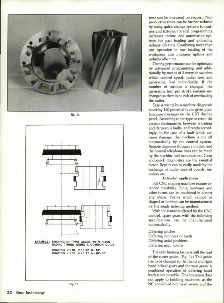
Rg.14
EXAMPLE: SHAPING OF TWO GEA'RS WITH IflXEO,RADIAL TIMING USIING A COMMON GUIDE
SHAPING I" '18 I m I 1.92 I b I 113"SHAPING Z I 30, m. 1.71 I til 19'· 30'
Fig. IS
22 GearTechnology
'tel's) can be increased on request. Nonproductive times can be furtller reducedby using quick change systems for rut-ters and fixtures, Parallel programm.ingincreases uptime" and automation sys-tems for part loading and unloadingreduces idle time. Combining more thanone operation in one loading of theworkpiece also increases uptime andreduces idle time.
Cutting performance can be optimizedby advanced programming and addi-tionally by means of 3 override switcheswhich eontro! speed, radial feed andgenerating feed individuaUy. If thenumber ,of strokes is changed, thegenerating feed per stroke remains un-changed so there is no risk of overloadingthe cutter,
Easy servicing by a machine diagnosticcovering 100 potential faults gives plainlanguage messages on the CRT displaypanel. Aocon::ling to the type or error. thesystem distinguishes between warningsand dangerous faults. and reacts accord-ingly. Inthe case of a fault which cancause damage, the machine is cut offautomatically by the control system.Remote diagnosis through a modem andthe normal telephone lines can be madeby the machine tool manutacrerer, Clearand quick diagnostics are the essentialfactor, Repairs can be easily made by theexchange of faulty control boards, en-coders etc.
Ex~endedl applicationsFull CNC shaping machines feature 'ex-
tended flexibility. Slots, keyways andother forms can be machined in almostany shape, Forms which cannot beshaped or hobbed can be manufacturedby the single indexing method.
With the features offered by the CNCcontrol. spare gears with the followingspecifications can be manufacturedautomatically.
Differing pitchesDiffering numbers of teethDiffering axial positionsDiffering gear widths
The only limiting factor is still the leadof the cutter guide. (Fig. 14) This guidehas to be changed for left hand and righthand helical gears and for spur gears; acombined operation of differing handleads is not possible. This limitation doesnot apply to hobbing machines. astheNC controlled hob head swivel and the
QUICK C~AHGE SYSTEMS
CUTTER ~DAPTOR QUICKCIIANGE SYSTEM
ClAMP(Nr. FIXTUR£QUICK 'CIIANGE,~YSTEM
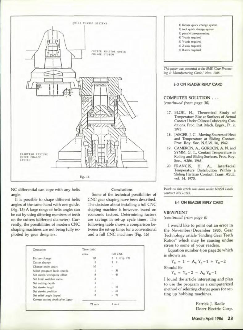
Fig. 16
NC dill,erential can cope with any helixangle.
It is possible to, shape different helixangles of the same hand with one guide.(Fig. 15) A large range of helix angles canbe cut by using differing numbers of teethon the cutters (different diameter). Cur-rently, the possibilities of modem CNCshaping machines are not being fully ex-ploited by gear designers.
CondusionsSome of the technical possibilities of
CNC gear shaping have been described.The decision about installing a fun CNCshaping machine is however, based oneconomic factors. Determining factorsare savings in set-upcyde times. Thefollowing table shows a comparison be-tween the set-up times for a conventionaland a full CNC machine: (Fig. 16)
Operation Time (min)cony full CNC
5 1) IFig. 19)
1 2)Fil<ture changeCulter changeChange index gearsSelect program I~ speedsSet culter/workpiece offsetSet limit switches radialSet culfing depthSet stroke lengthSet stroke positionSet relief angje (taper)
Cornd cutting depth alter I gear
205
101831
55
8
- 3)- 4)
- 51- 6)-7)
71. min :7 min
1) fixture quick change $lf tern2) tool quid chlfl~e system3) j)OU'oillel program!l1lng4)'t'-a:ci.s requi~5) V·axis required6) Z-a:cis required7) s-""js, requimf
This paper was presenta:il1t the SME "Cear ~ing & Manufacturing ainU:, W Nov. 1985.
IE-3 ON READER' IREPlY CAIRO
COMPUTER SOLUTION .....(continued from page 30)
17. BLOK, H., Theoretieal Study ofTempera'lUre Rise al Surfaces of ActuaJCant ct Under Oiliness LUbricating Con-ditions. Proc. Inst. Mech. En,sn., Pil. 2,1973.
18. JAEGER,J. C., Moving Sources of Heatand Temperature at Sliding Contact.Proc. Roy. Soc. N.S.W. 76, 1942.
19. CAMERON, A., GORDON, A. N. andSYMM, G. T., Contact Temperature inRolling and Sliding Surfaces. Pnx. Roy.Soc., A286, 1965.
20. FRANCIS, H. A., InterfacialTemperatur-e Distribution Within a.Slidi.ngHertzian Contact Trans. ASlE,vol. 14, 1970.
Work ot! this article was dOl1e under NASA Lewiscontract NSG-JI4J.
E-l ON READER RERLYCARD
VIEWPOINT(continued from page 6)
I would like to point out an error inthe November/December 1985, GearTechnologyarticle "Finding Gear TeethRatios" which may be causing unduestress to some of y'OUf readers.
Equati.on number 4! 'on page 26 whichis shown as:
Yn = 1 - An Yn-l + Yn-2Should .Be
Yn '" Yn-2 - An Yn-l
[ found the article i.n'teresting and planto use the program asa computenzedmethod of selecting change gears for set-ting up hob bing machines.
Patrick ]. Ra.d1eDoerr Electric Corp.
March/April 1986 23,


![Cutting costs for 1,800 gears [€] BALINIT ALTENSA ... · Gear cutting applications such as hobbing, gear shaping and bevel gear cutting must meet continually rising requirements:](https://img.pdfslide.net/doc/110x75/5e7108ffdcc0782fe1199b74/cutting-costs-for-1800-gears-a-balinit-altensa-gear-cutting-applications.jpg)