Embed Size (px)
Citation preview
Coal Combustion Residuals (CCR)Bottom Ash Transfer (BAT) ImpoundmentsGroundwater Detection Monitoring Plan
Revision 0Rawhide Energy StationLaramie County, Colorado
Platte River Power Authority
Project Number: 60514655
October 10, 2017
Environment Prepared forPlatte River Power AuthorityFort Collins, CO
Submitted byAECOMFort Collins, ColoradoOctober 2017
Coal Combustion Residuals (CCR)Bottom Ash Transfer (BAT) ImpoundmentsGroundwater Detection Monitoring Plan
Rawhide Energy StationLarimer County, Colorado
Revision 0
_________________________________Prepared ByRichard Henry, Principal Hydrogeologist
_________________________________Reviewed ByGregg Somermeyer, P.E., Senior Engineer
_________________________________Approved ByGeoff Webb, Senior Project Manager
AECOM BAT Impoundments Groundwater Detection Monitoring Plan Platte River Power Authority i
October 2017
1 Introduction .............................................................................................................................................. 1-11.1 Background ....................................................................................................................................... 1-11.2 Purpose ............................................................................................................................................ 1-1
2 Detection Monitoring Program ................................................................................................................. 2-12.1 Site Hydrogeology ............................................................................................................................. 2-12.2 Monitoring Well Network.................................................................................................................... 2-12.3 Sampling Frequency ......................................................................................................................... 2-22.4 Analytical Parameters ....................................................................................................................... 2-22.5 Reporting .......................................................................................................................................... 2-2
3 Groundwater Sampling and Analysis ...................................................................................................... 3-13.1 Field Procedures ............................................................................................................................... 3-13.2 Investigation Derived Waste .............................................................................................................. 3-13.3 Sample Preservation and Shipment................................................................................................... 3-13.4 Analytical Program ............................................................................................................................ 3-13.5 Chain-of-Custody Control .................................................................................................................. 3-23.6 Quality Assurance and Quality Control .............................................................................................. 3-2
4 Statistical Methodology............................................................................................................................ 4-14.1 Regulatory Guidance......................................................................................................................... 4-14.2 Statistical Analysis Approach............................................................................................................. 4-24.3 Interwell Statistical Approach............................................................................................................. 4-2
5 Assessment Monitoring ........................................................................................................................... 5-15.1 Triggers and Timing .......................................................................................................................... 5-15.2 Verification Resampling ..................................................................................................................... 5-15.3 Alternate Source Demonstration ........................................................................................................ 5-15.4 Assessment Monitoring Program ....................................................................................................... 5-1
6 Limitations ................................................................................................................................................ 6-17 References ................................................................................................................................................ 7-1
Table of Contents
AECOM BAT Impoundments Groundwater Detection Monitoring Plan Platte River Power Authority ii
October 2017
List of Tables
Table 1 Monitoring Well Construction Details
Table 2 Analytical Parameters, Methods, and Sampling Frequency
List of Figures
Figure 1 Rawhide Energy Station – Site Layout
Figure 2 Bottom Ash Transfer Impoundments – Monitoring Well Network
List of Appendices
Appendix A Boring and Monitoring Well Completion Logs
Appendix B Standard Operating Procedures (SOPs)
SOP No. 001 Chain-of-Custody Procedures
SOP No. 002 Package and Shipment of Environmental Samples
SOP No. 003 Decontamination of Field Equipment
SOP No. 004 Water Level Measurements
SOP No. 005 Low Flow Groundwater Sampling

AECOM BAT Impoundments Groundwater Detection Monitoring Plan Platte River Power Authority iii
October 2017
List of Acronyms
AECOM AECOM Technical Services, Inc.
amsl above mean sea level
ANOVA analysis of variance
BAT Bottom Ash Transfer
bgs below ground surface
BNSF Burlington Northern San Francisco Railway Company
CBSGs Colorado Basic Standards for Groundwater
CCR coal combustion residuals
CDPHE Colorado Department of Public Health and Environment
CFR Code of Federal Regulations
COC chain-of-custody
EDOP Engineered Design and Operations Plan
EPA U.S. Environmental Protection Agency
ft feet
MS/MSD matrix spike/matrix spike duplicate
Plan BAT Impoundments Groundwater Detection Monitoring Plan
PRPA Platte River Power Authority
Site Rawhide Energy Station
SOPs Standard Operating Procedures
QA/QC Quality assurance and quality control
RCRA Resource Conservation and Recovery Act
TDS total dissolved solids
AECOM BAT Impoundments Groundwater Detection Monitoring Plan Platte River Power Authority 1-1
October 2017
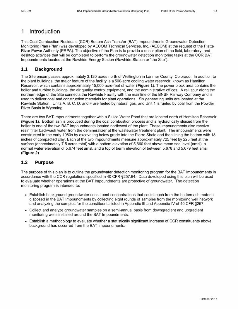
1 IntroductionThis Coal Combustion Residuals (CCR) Bottom Ash Transfer (BAT) Impoundments Groundwater DetectionMonitoring Plan (Plan) was developed by AECOM Technical Services, Inc. (AECOM) at the request of the PlatteRiver Power Authority (PRPA). The objective of the Plan is to provide a description of the field, laboratory, anddesktop activities that will be completed to perform the groundwater detection monitoring tasks at the CCR BATImpoundments located at the Rawhide Energy Station (Rawhide Station or “the Site”).
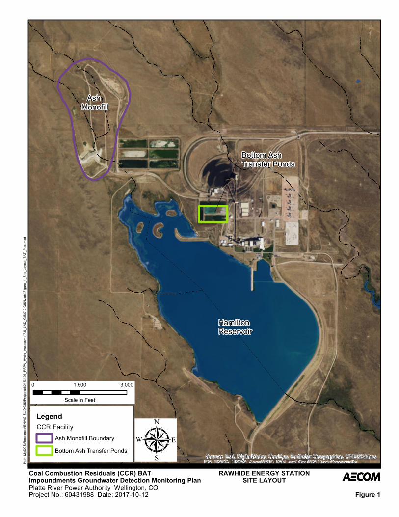
1.1 BackgroundThe Site encompasses approximately 3,120 acres north of Wellington in Larimer County, Colorado. In addition tothe plant buildings, the major feature of the facility is a 500-acre cooling water reservoir, known as HamiltonReservoir, which contains approximately 15,000 acre-feet of water (Figure 1). The power block area contains theboiler and turbine buildings, the air quality control equipment, and the administrative offices. A rail spur along thenorthern edge of the Site connects the Rawhide Facility with the mainline of the BNSF Railway Company and isused to deliver coal and construction materials for plant operations. Six generating units are located at theRawhide Station. Units A, B, C, D, and F are fueled by natural gas, and Unit 1 is fueled by coal from the PowderRiver Basin in Wyoming.
There are two BAT impoundments together with a Sluice Water Pond that are located north of Hamilton Reservoir(Figure 1). Bottom ash is produced during the coal combustion process and is hydraulically sluiced from theboiler to one of the two BAT impoundments located northwest of the plant. These impoundments also receiveresin filter backwash water from the demineralizer at the wastewater treatment plant. The impoundments wereconstructed in the early 1980s by excavating below grade into the Pierre Shale and then lining the bottom with 18inches of compacted clay. Each of the two impoundments measure approximately 725 feet by 225 feet at thesurface (approximately 7.5 acres total) with a bottom elevation of 5,660 feet above mean sea level (amsl), anormal water elevation of 5,674 feet amsl, and a top of berm elevation of between 5,678 and 5,679 feet amsl(Figure 2).
1.2 Purpose
The purpose of this plan is to outline the groundwater detection monitoring program for the BAT Impoundments inaccordance with the CCR regulations specified in 40 CFR §257.94. Data developed using this plan will be usedto evaluate whether operations at the BAT Impoundments are protective of groundwater. The detectionmonitoring program is intended to:
∂ Establish background groundwater constituent concentrations that could leach from the bottom ash materialdisposed in the BAT Impoundments by collecting eight rounds of samples from the monitoring well networkand analyzing the samples for the constituents listed in Appendix III and Appendix IV of 40 CFR §257.
∂ Collect and analyze groundwater samples on a semi-annual basis from downgradient and upgradientmonitoring wells installed around the BAT Impoundments.
∂ Establish a methodology to evaluate whether a statistically significant increase of CCR constituents abovebackground has occurred from the BAT Impoundments.
AECOM BAT Impoundments Groundwater Detection Monitoring Plan Platte River Power Authority 2-1
October 2017
2 Detection Monitoring Program
2.1 Site Hydrogeology
The hydrogeology of the Rawhide Station is discussed in the Engineering Design and Operations Plan (EDOP;PRPA 1980) and in the “Final Report Investigation of the Groundwater Monitoring Program for the Bottom AshDisposal Site,” conducted by Lidstone and Anderson (1989). According to the 1980 EDOP, hydrogeology of theRawhide Station site was originally investigated by drilling and installing twenty-three (23) piezometers inconjunction with the original geotechnical investigation of the site prior to construction of the facility. Data from thepiezometers indicated that a groundwater table exists within the weathered and fractured Pierre Shale bedrock atsome locations below the site and in alluvial deposits along Coal Creek. The report indicated that the depth togroundwater varied across the site from 11 to 67 feet (ft) below ground surface (bgs) and generally flowed to thesouth-southeast. The shallow water table, as explained in the 1980 EDOP, was reported to be directly rechargedby infiltration from precipitation and surface runoff.
Following construction and operation of the Rawhide Energy Station, Lidstone and Anderson (1989) concludedthat sufficient groundwater data were collected to determine a mound had formed in the shallow, weathered, andfractured Pierre Shale in the vicinity of the cooling water reservoir. After a review of available groundwater levelinformation for the Site, AECOM concluded that the BAT Impoundments are hydraulically upgradient of anygroundwater mound created by the cooling water reservoir.
The uppermost water-bearing stratum beneath the BAT Impoundments is identified as the weathered andfractured Pierre Shale which lies approximately 3 to 17 feet below ground surface (ft bgs) and appears to belargely recharged by leakage from the BAT Impoundments. Groundwater beneath the BAT Impoundments ispresent under water table conditions, where the depth to groundwater ranges from approximately 4 to 15 ft bgs.Groundwater flow is generally radial from the BAT Impoundments. Regional groundwater flow is from north tosouth towards Hamilton Reservoir, generally following the topographic slope.
The existence of a perennial water table beneath the BAT Impoundments is not known. Previously reportsindicate that little to no groundwater was present in geotechnical boreholes completed in the area of the BATImpoundments at the time of construction (Black & Veatch Consulting Engineers, 1979). The BAT Impoundmentsare constructed on a local topographic high, suggesting that groundwater, if present, likely flowed away from thearea of the impoundments prior to construction. The currently observed water table beneath the BATImpoundments appears to be a perched saturated zone in the underlying weathered and fractured Pierre Shalewhich is most likely sourced by leakage from the impoundments as suggested by the radial flow pattern definedby the potentiometric contours. The water-bearing interval identified beneath the perimeter of the BATimpoundments area would likely be unsaturated (dry) if the BAT impoundments and Sluice Water Pond were notpresent.
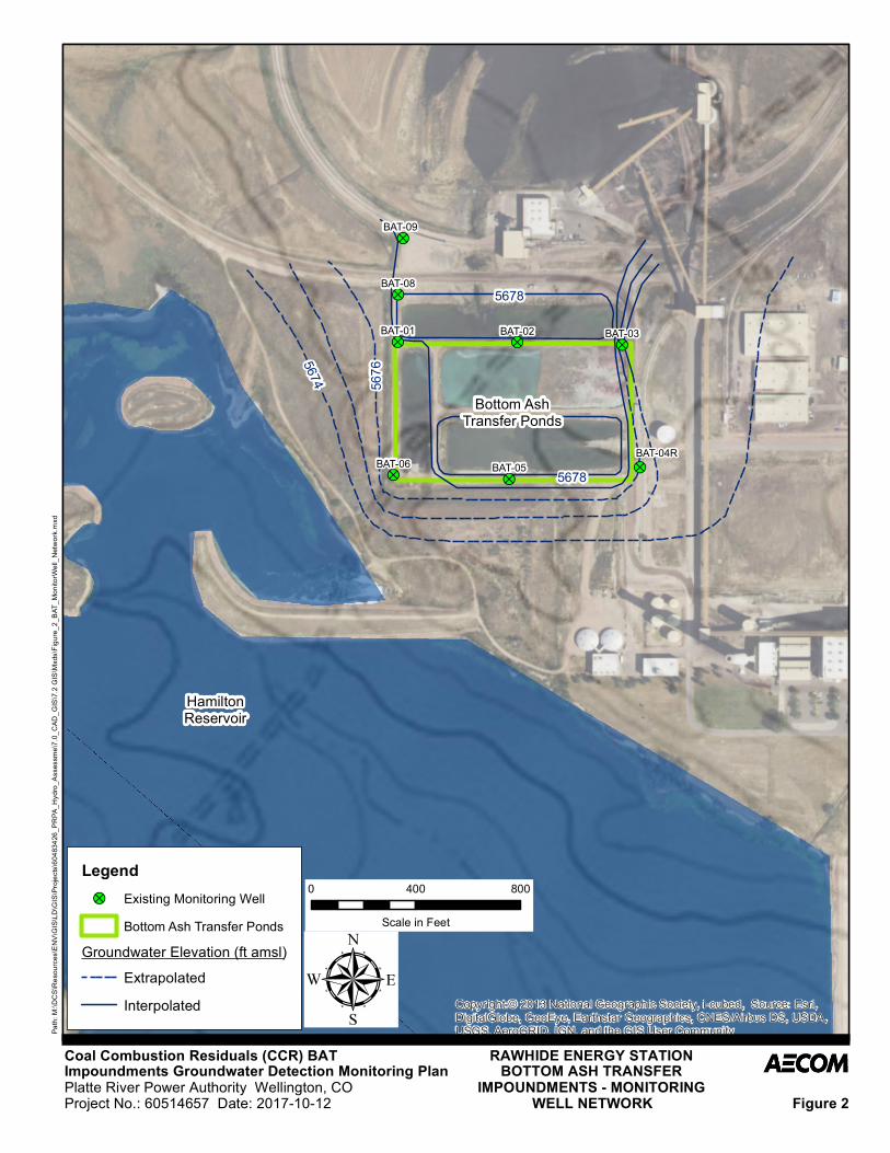
2.2 Monitoring Well Network
The groundwater detection monitoring network for the BAT Impoundments is depicted on Figure 2. The BATImpoundments network includes one upgradient well, BAT-09, that will be used to establish backgroundgroundwater constituent concentrations, and seven downgradient wells, BAT-01 through BAT-06, and BAT-08,along the perimeter of the BAT Impoundments. Historical monitoring well BAT-04 was destroyed and wasreplaced by monitoring well BAT-04R. These monitoring wells were installed in 2016 to comply with the CCRRule. Monitoring well BAT-09 was selected as an upgradient well based on the regional north to southgroundwater flow towards Hamilton Reservoir. The remaining wells were installed because there is localizedradial groundwater flow pattern around the BAT Impoundments.
The wells were drilled using a hollow-stem auger rig equipped with 8.25-inch augers. The wells were completedwith 2-inch diameter polyvinyl chloride (PVC) casing and 0.01-inch factory slotted, 10-foot long screen. The wellannulus was filled with 20/40 silica sand to approximately 2 feet above the top of screen. A 2-foot thick, 3/8-inchhydrated bentonite chip seal was emplaced above the sand pack, and neat cement grout was injected from thetop of the bentonite seal to ground surface. The wells were completed with flush-mounted protective covers. The
AECOM BAT Impoundments Groundwater Detection Monitoring Plan Platte River Power Authority 2-2
October 2017
boring logs and well construction diagrams for the monitoring wells are included in Appendix A. Table 1summarizes well construction details for the BAT Impoundments detection monitoring wells.
2.3 Sampling FrequencyTo establish background and downgradient concentrations for the detection monitoring program, wells in the BATImpoundments monitoring network were sampled approximately bi-monthly (every two months). The eightsampling rounds began on September 12, 2016 and were completed on July 13, 2017, prior to the October 17,2017 deadline established in the CCR Rule (40 CFR §257.94). After October 17, 2017, the detection monitoringsampling frequency will be semi-annual (Table 2).
2.4 Analytical Parameters
During the eight rounds of baseline detection monitoring, samples were collected from the BAT Impoundmentswells and analyzed for the constituents listed in 40 CFR §257, Appendices III and IV. This list includes thegeneral chemistry parameters pH and total dissolved solids (TDS); anions (chloride, fluoride, and sulfate);combined radium-226+228, and several metals as shown on Table 2. Groundwater samples will not be field-filtered so that reported metals concentrations represent “total recoverable metals” as required by the CCR Rule.
Since the initial eight rounds of baseline detection monitoring have been completed, the analyte list will bereduced to the indicator parameters listed in Appendix III of 40 CFR §257. This shorter list, which includes boron,calcium, chloride, fluoride, sulfate, and TDS (Table 2), will remain the focus of detection monitoring until the BATImpoundments are closed or assessment monitoring is triggered. Groundwater pH will continue to be monitoredas a field parameter.
2.5 Reporting
To comply with the CCR Rule, an Annual Monitoring and Corrective Action Report will be prepared for the BATImpoundments after the first eight (8) rounds of detection monitoring is completed. This initial report will becompleted no later than January 31, 2018, and annually thereafter, and will be prepared in accordance with therequirements of 40 CFR §257.90. The annual report will document the status of the detection monitoring programfor the BAT Impoundments, summarize key actions completed, describe any problems encountered, discussactions to resolve the problems, and identify key activities for the upcoming calendar year. The annual report willbe considered complete when it is placed in the facility operating record. .Other information required to beincluded in the annual report is listed in 40 CFR §257.90.
AECOM BAT Impoundments Groundwater Detection Monitoring Plan Platte River Power Authority 3-1
October 2017
3 Groundwater Sampling and AnalysisThis section describes procedures that will be used at the Site for groundwater monitoring, sampling, andanalysis.
3.1 Field Procedures
Groundwater sampling and analysis will be conducted in general accordance with the following AECOM StandardOperating Procedures (SOPs) that are included in Appendix B:
∂ SOP No. 001 Chain-of-Custody Procedures∂ SOP No. 002 Package and Shipment of Environmental Samples∂ SOP No. 003 Decontamination of Field Equipment∂ SOP No. 004 Water Level Measurements∂ SOP No. 005 Low Flow Groundwater Sampling
Significant deviations from the SOPs will be recorded in the field notes. Field notes will be recorded by samplingpersonnel. The field notes will include sampler name(s), well identification numbers, the date and time, instrumentcalibration notes, water-level measurements, well purging volumes, deviations from the SOPs, and other notablesite observations. These records are copied to the project file and included in the Annual Monitoring andCorrective Action Report.
3.2 Investigation Derived Waste
Groundwater monitoring sampling and analysis has been performed at Site wells for a number of years. Theresults for wells in the vicinity of the BAT Impoundments have been reviewed relative to the Colorado BasicStandards for Groundwater (CBSGs). The results for analytes with associated CBSGs were reported at valuesbelow primary CBSGs for samples collected in 2014 and 2015. Therefore, based on this information, and as thischaracterization of the groundwater demonstrates compliance with CBSGs, purge water generated duringsampling will be discharged to ground surface. The purge water will be discharged by pouring it on the ground ina flat area away from the well head. The field sampler will spread out the purge water as much as possible topromote evaporation and reduce the potential for the water to runoff or infiltrate into the subsurface.
3.3 Sample Preservation and Shipment
Samples will be preserved in the field as appropriate, and sample containers will be labeled and placed inappropriate shipping containers. Table 2 lists the required preservative for each analytical constituent. Samplecontainers will be placed on ice following sample collection and during transport to the laboratory. Other samplepreservatives include nitric acid for metals and hydrochloric acid for mercury analysis. The sample bottles foranalysis of metals and mercury will be preserved by the laboratory prior to sample collection. Samples will betransported under chain-of-custody (COC) control to a certified analytical laboratory.
Following collection, samples will be preserved in the field as appropriate, then labeled and secured in appropriateshipping containers. Table 2 lists the required preservative for each analytical constituent. The main preservativeused will be to place the samples on ice during sample collection and transport to the laboratory. Other samplepreservatives include nitric acid for metals and hydrochloric acid for mercury analysis. The sample bottles formetals and mercury will be preserved by the laboratory prior to sample collection.
3.4 Analytical Program
The list of Appendices III and IV analytes, analytical methods, and sample preservatives are shown on Table 2.Analyses will be conducted by a certified analytical laboratory. Both Appendix III and IV analytes will be analyzedduring the first eight sampling events of detection monitoring to establish background. After October 2017, whenthe detection monitoring sampling frequency changes to semi-annual, the Appendix III list of boron, calcium,
AECOM BAT Impoundments Groundwater Detection Monitoring Plan Platte River Power Authority 3-2
October 2017
chloride, fluoride, sulfate, and TDS will be analyzed and reported. If assessment monitoring is subsequentlytriggered, both the Appendix III and IV list of analytes will be analyzed. Groundwater pH will continue to bemonitored as a field parameter.
3.5 Chain-of-Custody Control
Standard chain-of-custody (COC) procedures will be followed from sample collection and throughout theanalytical process. Custody is recorded through a series of signatures on the COC form as sample possessionchanges from one person or organization to another. For each sample location, the sample name, date and timeof collection, and requested analyses will be recorded on the COC form. COC records will be maintained andincluded in the Annual Monitoring and Corrective Action Report.
3.6 Quality Assurance and Quality Control
Quality assurance and quality control (QA/QC) measures will be implemented to collect reliable and valid field andanalytical data. The QA/QC program will include collecting field duplicate samples to assess error associated withsample methodology and analytical procedures. At a minimum, one field duplicate will be collected per 20samples or individual sampling event. Equipment blanks will also be collected when sampling equipment is re-used at multiple wells to assess the efficacy of equipment decontamination techniques. In addition, matrixspike/matrix spike duplicate (MS/MSD) samples will be used to monitor lab performance and the degree to whichmatrix interferences affect the reported concentration of an analyte. At least one equipment blank and oneMS/MSD will be collected for every 20 samples or per sampling event. A laboratory quality control report for eachdetection monitoring event will be provided by the lab and included in the data validation packet.
The data quality will be assessed by conducting a data review and validation on the laboratory analytical datapackages. For each sampling event, a technical memorandum will be prepared and included within the AnnualMonitoring and Corrective Action Report. The technical memorandum will summarize the usability of theanalytical data with respect to satisfying project data quality objectives.
AECOM BAT Impoundments Groundwater Detection Monitoring Plan Platte River Power Authority 4-1
October 2017
4 Statistical Methodology
4.1 Regulatory Guidance
Regulatory guidance provided in 40 CFR §257.90 specifies that a CCR groundwater monitoring program includeselection of the statistical procedures to be used for evaluating groundwater quality data as required by 40 CFR§257.93. Groundwater quality monitoring data will be collected under the detection monitoring program outlined inthis plan and includes collection and analysis of a minimum of eight independent groundwater samples for thebackground and downgradient compliance wells as required by 40 CFR §257.94(b). The groundwater sampleswill be analyzed for the constituents listed in 40 CFR §257 Appendices III and IV.
After the initial eight rounds of groundwater samples are collected and analyzed, these data must be statisticallyevaluated to determine if there are any statistically significant increases over background for the Appendix IIIconstituents. In determining whether a statistically significant increase has occurred, the constituentconcentrations at the downgradient wells (ASH-03, ASH-04, and ASH-05) and the background well (ASH-01) willbe compared using one or more of the statistical methods presented in Sections 4.2 and 4.3.
The guidance in 40 CFR §257.93(f) outlines the statistical methods available to evaluate groundwater monitoringdata. The statistical test(s) chosen will be conducted separately for each constituent in each monitoring well andwill be appropriate for the constituent data and their distribution. The available statistical methods include thefollowing:
∂ A parametric analysis of variance (ANOVA) followed by multiple comparison procedures to identifystatistically significant evidence of contamination. The method must include estimation and testing of thecontrasts between each compliance well’s mean and the background mean levels for each constituent;
∂ An ANOVA based on ranks followed by multiple comparison procedures to identify statistically significantevidence of impacts. The method must include estimation and testing of the contrasts between eachcompliance well’s median and the background median levels for each constituent;
∂ A tolerance or prediction interval procedure, in which an interval for each constituent is established from thedistribution of the background data and the level of each constituent in each compliance well is compared tothe upper tolerance or prediction limit;
∂ A control chart approach that gives control limits for each constituent; or∂ Another statistical test method that meets the performance standards outlined in the paragraph below.
The chosen statistical method will comply with the performance standards specified in 40 CFR §257.93(g), asappropriate, based on the statistical test method used. The performance standards include the following:
∂ The statistical method used to evaluate groundwater monitoring data will be appropriate for the constituentdistribution (i.e., parametric or nonparametric).
∂ If an individual well comparison procedure is used to compare an individual compliance well constituentconcentration with background constituent concentrations or a groundwater protection standard, the testshall be done at a Type I error level no less than 0.01 or 0.05, depending on the method chosen. Thisperformance standard does not apply to tolerance intervals, prediction intervals, or control charts.
∂ If a control chart approach is used to evaluate groundwater monitoring data, the specific type of control chartand its associated parameter values shall be such that this approach is at least as effective as any of theother statistical analysis approaches specified above.
∂ If a tolerance interval or a prediction interval is used to evaluate groundwater monitoring data, the levels ofconfidence and, for tolerance intervals, the percentage of the population that the interval must contain, shallbe such that this approach is at least as effective as any of the other statistical analysis approaches specifiedabove.
∂ The statistical method must account for data below the limit of detection with one or more statisticalprocedures that shall be at least as effective as any of the other statistical analysis approaches specifiedabove.
AECOM BAT Impoundments Groundwater Detection Monitoring Plan Platte River Power Authority 4-2
October 2017
∂ If necessary, the statistical method must include procedures to control or correct for seasonal and spatialvariability as well as temporal correlation in the data.
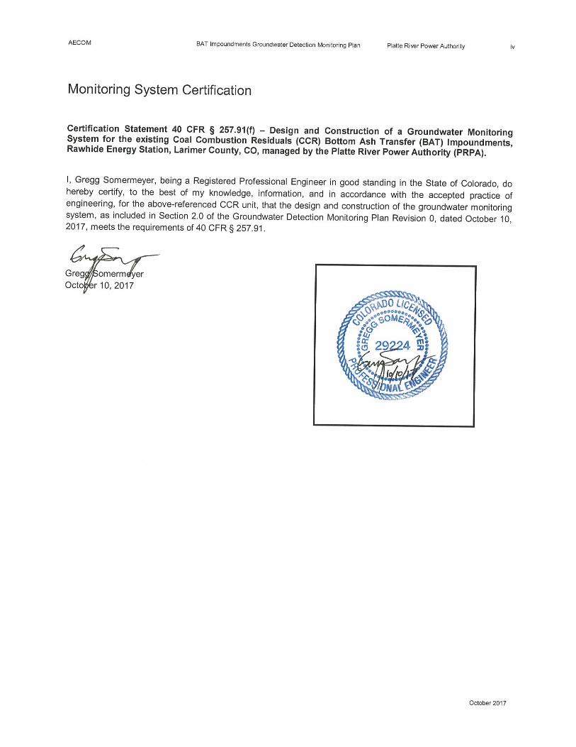
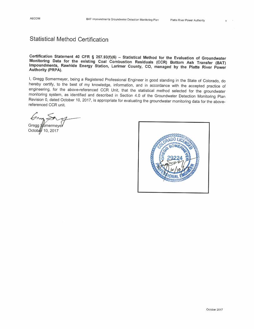
Per 40 CFR §257.93(h)(2), statistical analysis of the first eight rounds of data must be completed within 90 daysafter completing the initial groundwater sampling and analysis to determine whether there has been a statisticallysignificant increase over background for any constituent. The first eight rounds of groundwater sampling andanalysis must be completed no later than October 17, 2017. In accordance with 40 CFR §257, the RawhideFacility must obtain a certification from a qualified professional engineer stating that the selected statisticalmethod is appropriate for evaluating the groundwater monitoring data for the CCR management area. Thecertification must include a narrative description of the statistical method selected to evaluate the groundwatermonitoring data.
Assessment monitoring is required per 40 CFR §257.95 whenever a statistically significant increase overbackground has been detected for one or more of the indicator parameters listed in 40 CFR §257 Appendix III.An assessment monitoring program also includes annual groundwater sampling and analysis for the constituentslisted in 40 CFR §257 Appendix IV. The purpose of assessment monitoring is to determine if releases of CCRconstituents have occurred to groundwater.
The facility can return to detection monitoring once assessment monitoring results are at or below backgroundvalues for two consecutive assessment monitoring events. If the assessment monitoring demonstrates anexceedance of a groundwater protection standard for any of the CCR constituents specified in 40 CFR §257Appendices III and IV, groundwater corrective action must be initiated.
4.2 Statistical Analysis Approach
There is no single method of statistical analysis that is appropriate for each groundwater constituent dataset. It ismost prudent to use a suite of statistical methods that are dependent on the data and their distributions. Thestatistical analyses can be based on an interwell and/or an intrawell approach for the purpose of determining if theBAT Impoundments have impacted groundwater quality. The statistical algorithms used for the interwell andintrawell approaches are chosen based on the groundwater constituent data and their distributions as well asconsideration of natural seasonally- or spatially-varying groundwater constituent concentrations.
The initial eight rounds of baseline groundwater monitoring data were concurrently collected and analyzed for the40 CFR §257 Appendices III and IV constituents. These data will be used to represent background groundwaterquality for the BAT Impoundments and will be used to determine if the BAT Impoundments have impacteddowngradient groundwater quality. The initial eight rounds of detection monitoring sampling and analysis werecompleted prior to the October 17, 2017 deadline established in the CCR Rule (40 CFR §257.94).
A preliminary, exploratory statistical analysis was conducted after the initial eight rounds of baseline data wereobtained to initially assess the constituent data and determine the most appropriate statistical approach(es) for thedata. The data were examined for outliers and the percentage of non-detect values to verify that the datacollected are suitable for statistical analysis. The data were also examined using goodness-of-fit tests todetermine the most appropriate statistical distribution and time series plots and areal maps were used todetermine if seasonal or spatial variations in constituent concentrations were present. Based on this preliminaryevaluation of the data, an interwell statistical approach was selected as appropriate for evaluating groundwater atthe Rawhide Facility, as described in Section 4.3.
Per 40 CFR §257.93(h)(2), statistical analysis of all eight rounds of the initial groundwater monitoring data mustbe completed within 90 days after completing groundwater sampling and analysis to determine whether there hasbeen a statistically significant increase over background for any Appendix III constituent.
4.3 Interwell Statistical Approach
Interwell tests compare the statistical differences between (upgradient) background and downgradient compliancewells. An interwell statistical approach will be used during detection monitoring for the following reasons:
AECOM BAT Impoundments Groundwater Detection Monitoring Plan Platte River Power Authority 4-3
October 2017
∂ Sufficient data are available in the upgradient background well to ensure adequate degrees of statisticalpower to detect real exceedances above background levels, and also reasonable control over the site-widefalse positive rate so that spurious exceedances have little chance of being identified.
∂ Although there is evident spatial variation among most, if not all, of the Appendix III constituents, it is unclearto what extent the similarly evident variation among the downgradient wells is due strictly to naturaldifferences in groundwater quality and/or other factors unrelated to management of the CCR ash. Becauseof this uncertainty, an interwell comparison strategy appears to be initially more appropriate for the RawhideFacility.
As a caveat to this approach, for constituents that occur naturally and vary substantially in concentration acrossthe Rawhide Facility due to natural hydrogeologic or geochemical factors — thus, exhibiting significant spatialvariability — an interwell testing scheme will not always be helpful. Constituent concentrations greater thanbackground might be attributed to anthropogenic contamination using an interwell approach, when the differencesare actually natural and due to locally varying distributions of groundwater constituents. In such cases, anintrawell approach may be warranted.
Furthermore, there is no requirement either in RCRA or the CCR Rule to use exactly the same statistical methodor approach for every constituent. Depending on characteristics of the Rawhide Facility and data that arecollected, a mix of interwell and intrawell tests may be warranted. At this site, the initial statistical screeningsuggests that interwell comparisons are most appropriate despite evident spatial variability. However, thatconclusion could change as additional data are collected during future detection monitoring. If new informationindicates that constituent concentrations remain relatively stable and that the existing spatial variation is unrelatedto the BAT Impoundments, a modification of the statistical approach to intrawell testing may be recommended forone or more constituents.
Under an interwell statistical approach in detection monitoring, the actual statistical method(s) chosen will bedetermined based on the constituent data distribution (as outlined below), which in turn is influenced both by thepercentage and pattern of non-detect measurements as well as the temporal stability of the concentration levels.
When (1) the percentage of non-detects is low to moderate (i.e., less than 50-60 percent), (2) the backgrounddata can be normalized (perhaps via a standard transformation), and (3) the results are stationary (i.e., stableover time), the following statistical methods are highly recommended by USEPA (2009):
∂ Parametric interwell prediction limit methods with retesting; or∂ Interwell control charts with retesting.
When the background data cannot be normalized (perhaps due to a large percentage of non-detects), but thedata are stationary (i.e., stable over time), the following statistical method is recommended by USEPA (2009):
∂ Non-parametric interwell prediction limits with retesting.
Note that the specific retesting method in each of these options will be chosen to account for the size of the wellnetwork, the amount of background data available, the number of constituents being monitored, the site-specificmix of intrawell and interwell tests, and the impact of these factors on the statistical power and accuracy of thetest. At this site, the upgradient background wells relative to the number of downgradient wells to be tested on asemi-annual basis will enable use of a 1-of-2 retesting plan. This necessitates collection of a single independentresample at any location in which the initial routine measurement exceeds its respective statistical limit. Aconfirmed statistical exceedance will not be recorded unless both the initial measurement and resample valueboth exceed the statistical limit.
If the upgradient background data are non-stationary and thus exhibit a clear trend, it will suggest that factorsunrelated to the BAT Impoundments are impacting upgradient groundwater quality. Three general scenarios willbe considered:
AECOM BAT Impoundments Groundwater Detection Monitoring Plan Platte River Power Authority 4-4
October 2017
∂ Older background data may no longer be representative of current site conditions and may need to beexcluded from statistical calculations. In this case, the interwell statistical limits will be updated to includeonly the most representative background data.
∂ The compliance wells will be examined to see if similar trends are occurring downgradient. If so, a commontrend component will be estimated across the site and removed from every well. The residual data will thenbe used to construct revised statistical limits and tested as described in the above methods.
∂ If the trend in upgradient background wells is not reflected in downgradient wells, further investigation maybe needed to determine if the upgradient data still serve as a reasonable background with which to comparedowngradient compliance measurements. If not, the statistical approach will be modified to an appropriateintrawell strategy.
Because of the decision matrix needed to establish the correct statistical approach, the background data for eachconstituent will be periodically screened prior to construction of new or revised statistical limits. This screening willexamine the proportion and pattern of outliers and potential data anomalies (perhaps due to laboratory or fieldsampling factors), the presence or absence of statistically significant trends over time, the presence or absence ofstatistically significant outliers, and the identification of an appropriate statistical distribution. In particular, anyconfirmed background outliers will be excluded from statistical calculations, so as not to unduly bias the statisticallimits.
AECOM BAT Impoundments Groundwater Detection Monitoring Plan Platte River Power Authority 5-1
October 2017
5 Assessment Monitoring
5.1 Triggers and Timing
If through the statistical analyses discussed in Section 4.0, it becomes evident that a statistically significantincrease over background has occurred for one or more of the detection monitoring 40 CFR §257 Appendix IIIconstituents, documentation will be placed in the facility operating record indicating which constituents haveshown an increase. The facility would then have two options for continued groundwater monitoring at the BATImpoundments.
∂ The first option would be to evaluate whether a source other than the BAT Impoundments caused thestatistically significant increase, or whether the increase resulted from error in sampling, analysis, statisticalevaluation, or natural variation in groundwater quality.
∂ The second option would be to establish an assessment monitoring program for the BAT Impoundments inaccordance with 40 CFR §257.95. An assessment monitoring program also includes annual groundwatersampling and analysis for the constituents listed in 40 CFR §257 Appendix IV. The purpose of assessmentmonitoring is to determine if releases of CCR constituents have occurred from the BAT Impoundments. Ifthis option proves to be necessary, a notification will be placed in the facility operating record stating that anassessment monitoring program has been established. The facility is required to implement the assessmentmonitoring program within 90 days of confirming the statistically significant concentration increase.
Protocols that would be followed for each of these options are described below in Sections 5.2 through 5.4.
5.2 Verification Resampling
Verification resampling is an integral component of the statistical method outlined in Section 4.3. Verificationresampling provides a way to evaluate unexpected or errant sample results and can help avoid unnecessary entryinto assessment monitoring. A verification resample would only be collected from the well(s) where an outlier orstatistically significant concentration increase was observed, and only for the relevant analyte(s). The samesampling procedures used for detection monitoring would also be used for verification resampling. The facility willtake reasonable efforts to complete verification resampling within two weeks of identifying the need to resample.A statistically significant increase only is flagged when a verification sample confirms the initial result. A reportdocumenting this action will be developed in accordance with requirements of 40 CFR §257.94.
5.3 Alternate Source Demonstration
In addition to verification resampling, the facility may also choose to evaluate whether the statistically significantconcentration increase was derived from another source besides the BAT Impoundments. Such an evaluation, ifwarranted, may require specialized sample analyses to identify concentration inputs from other potential sources.Any report prepared as a result of this evaluation or as a result of verification sampling will be placed into thefacility operating record within 90 days of identifying the statistically significant concentration increase. The reportwill also be certified by a qualified groundwater scientist or professional engineer.
5.4 Assessment Monitoring Program
Assessment monitoring is required whenever a statistically significant increase over background has beendetected for one or more of the constituents listed in 40 CFR §257 Appendix III. A routine monitoring sampleresult will only be considered valid if the verification sample result confirms a statistically significant increase overbackground values. If this situation occurs, the facility will implement an assessment monitoring program within 90days of obtaining the verification resample result in accordance with 40 CFR §257.95. In assessment monitoring,the owner or operator of the CCR unit must sample and analyze the groundwater for all constituents listed in 40CFR §257 Appendix IV (Table 2) within 90 days of a confirmed statistically significant increase over background,and annually thereafter. Within 90 days of obtaining the initial assessment monitoring results, and on at least asemiannual basis thereafter, resample all monitoring wells and conduct analyses for all parameters in 40 CFR§257 Appendix III and for those constituents in 40 CFR §257 Appendix IV that show statistically significant

AECOM BAT Impoundments Groundwater Detection Monitoring Plan Platte River Power Authority 5-2
October 2017
increases above background in the initial assessment monitoring. All assessment monitoring results will beentered into the facility operating record as required by 40 CFR §257.95. The facility can return to detectionmonitoring once assessment monitoring results are at or below background values for two consecutiveassessment monitoring events.
AECOM BAT Impoundments Groundwater Detection Monitoring Plan Platte River Power Authority 6-1
October 2017
6 Limitations
The signature of Consultant’s authorized representative on this document represents that, to the best ofConsultant’s knowledge, information, and belief in the exercise of its professional judgment, it is Consultant'sprofessional opinion that the aforementioned information is accurate as of the date of such signature. Any opinionor decisions by Consultant are made on the basis of Consultant’s experience, qualifications, and professionaljudgment and are not to be construed as warranties or guaranties. In addition, opinions relating to environmental,geologic, and geotechnical conditions or other estimates are based on available data, and actual conditions mayvary from those encountered at the times and locations where data are obtained, despite the use of due care.
AECOM BAT Impoundments Groundwater Detection Monitoring Plan Platte River Power Authority 7-1
October 2017
Black & Veatch Consulting Engineers. 1979. Geotechnical Analysis, Report Platte River Power Authority RawhideProject, July 1979.
Lidstone & Anderson, Inc. 1989. Investigation of the Ground-Water Monitoring Program for the Bottom AshDisposal Site. March 1989.
Platte River Power Authority (PRPA). 1980. Engineering Report and Operational Plan for the Solid WasteDisposal Facility, Rawhide Energy Project, December 1980.
Smith Geotechnical. 2007. Revised Design and Operations Plan for the Solid Waste Disposal Facility RawhideEnergy Station. November 2007.
U.S. Environmental Protection Agency. 2009. Statistical Analysis of Groundwater Monitoring Data at ResourceConservation and Recovery Act (RCRA) Facilities. Unified Guidance. EPA 530-R-09-007. March. 884 pp.
U.S. Environmental Protection Agency. 2015. 40 CFR Parts 257 and 261 Hazardous and Solid WasteManagement System; Disposal of Coal Combustion Residuals from Electric Utilities; Final Rule. FederalRegister, v.80, no. 74, April 17, 2015, 201 pp.
7 References

AECOM BAT Impoundments Groundwater Detection Monitoring Plan Platte River Power Authority
October 2017
Tables
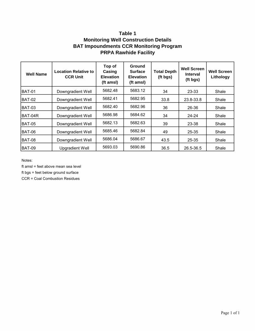
Table 1Monitoring Well Construction Details
BAT Impoundments CCR Monitoring ProgramPRPA Rawhide Facility
Well Name Location Relative toCCR Unit
Top ofCasing
Elevation(ft amsl)
GroundSurface
Elevation(ft amsl)
Total Depth(ft bgs)
Well ScreenInterval(ft bgs)
Well ScreenLithology
BAT-01 Downgradient Well 5682.48 5683.12 34 23-33 Shale
BAT-02 Downgradient Well 5682.41 5682.95 33.8 23.8-33.8 Shale
BAT-03 Downgradient Well 5682.40 5682.96 36 26-36 Shale
BAT-04R Downgradient Well 5686.98 5684.62 34 24-24 Shale
BAT-05 Downgradient Well 5682.13 5682.63 39 23-38 Shale
BAT-06 Downgradient Well 5685.46 5682.84 49 25-35 Shale
BAT-08 Downgradient Well 5686.04 5686.67 43.5 25-35 Shale
BAT-09 Upgradient Well 5693.03 5690.86 36.5 26.5-36.5 Shale
Notes:ft amsl = feet above mean sea levelft bgs = feet below ground surfaceCCR = Coal Combustion Residues
Page 1 of 1
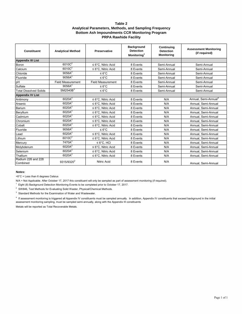
Table 2Analytical Parameters, Methods, and Sampling Frequency
Bottom Ash Impoundments CCR Monitoring ProgramPRPA Rawhide Facility
Constituent Analytical Method PreservativeBackground
DetectionMonitoring1
ContinuingDetection
Monitoring
Assessment Monitoring(if required)
Appendix III ListBoron 6010C2 ≤ 6°C, Nitric Acid 8 Events Semi-Annual Semi-AnnualCalcium 6010C2 ≤ 6°C, Nitric Acid 8 Events Semi-Annual Semi-AnnualChloride 9056A2 ≤ 6°C 8 Events Semi-Annual Semi-AnnualFluoride 9056A2 ≤ 6°C 8 Events Semi-Annual Semi-AnnualpH Field Measurement Field Measurement 8 Events Semi-Annual Semi-AnnualSulfate 9056A2 ≤ 6°C 8 Events Semi-Annual Semi-AnnualTotal Dissolved Solids SM2540B3 ≤ 6°C 8 Events Semi-Annual Semi-AnnualAppendix IV ListAntimony 6020A2 ≤ 6°C, Nitric Acid 8 Events N/A Annual, Semi-Annual4
Arsenic 6020A2 ≤ 6°C, Nitric Acid 8 Events N/A Annual, Semi-AnnualBarium 6020A2 ≤ 6°C, Nitric Acid 8 Events N/A Annual, Semi-AnnualBeryllium 6020A2 ≤ 6°C, Nitric Acid 8 Events N/A Annual, Semi-AnnualCadmium 6020A2 ≤ 6°C, Nitric Acid 8 Events N/A Annual, Semi-AnnualChromium 6020A2 ≤ 6°C, Nitric Acid 8 Events N/A Annual, Semi-AnnualCobalt 6020A2 ≤ 6°C, Nitric Acid 8 Events N/A Annual, Semi-AnnualFluoride 9056A2 ≤ 6°C 8 Events N/A Annual, Semi-AnnualLead 6020A2 ≤ 6°C, Nitric Acid 8 Events N/A Annual, Semi-AnnualLithium 6010C2 ≤ 6°C, Nitric Acid 8 Events N/A Annual, Semi-AnnualMercury 7470A2 ≤ 6°C, HCl 8 Events N/A Annual, Semi-AnnualMolybdenum 6020A2 ≤ 6°C, Nitric Acid 8 Events N/A Annual, Semi-AnnualSelenium 6020A2 ≤ 6°C, Nitric Acid 8 Events N/A Annual, Semi-AnnualThallium 6020A2 ≤ 6°C, Nitric Acid 8 Events N/A Annual, Semi-AnnualRadium 226 and 228Combined 9315/93202 Nitric Acid 8 Events N/A Annual, Semi-Annual
Notes:<6°C = Less than 6 degrees CelsiusN/A = Not Applicable. After October 17, 2017 this constituent will only be sampled as part of assessment monitoring (if required).1 Eight (8) Background Detection Monitoring Events to be completed prior to October 17, 2017.2 SW846, Test Methods for Evaluating Solid Waster, Physical/Chemical Methods.3 Standard Methods for the Examination of Water and Wastewater.
Metals will be reported as Total Recoverable Metals.
4 If assessment monitoring is triggered all Appendix IV constituents must be sampled annually. In addition, Appendix IV constituents that exceed background in the initialassessment monitoring sampling, must be sampled semi-annually, along with the Appendix III constituents
Page 1 of 1

AECOM BAT Impoundments Groundwater Detection Monitoring Plan Platte River Power Authority
October 2017
Figures
Bottom Ash Transfer Ponds
Ash Monofill
Hamilton Reservoir
Source: Esri, DigitalGlobe, GeoEye, Earthstar Geographics, CNES/AirbusDS, USDA, USGS, AeroGRID, IGN, and the GIS User Community
0 1,500 3,000
Scale in Feet
µLegendCCR Facility
Ash Monofill BoundaryBottom Ash Transfer Ponds
Figure 1
RAWHIDE ENERGY STATIONSITE LAYOUT
Platte River Power Authority Wellington, COProject No.: 60431988 Date: 2017-10-12
Path:
M:\D
CS\R
esou
rces\E
NV\G
IS\LD
\GIS
\Proj
ects\
6048
3426
_PRP
A_Hy
dro_A
sses
sme\7
.0_CA
D_GI
S\7.2
GIS
\Mxd
s\Figu
re_1_
Site_
Layo
ut_BA
T_Pla
n.mxd
Coal Combustion Residuals (CCR) BATImpoundments Groundwater Detection Monitoring Plan
!? !? !?
!?!?
!?
!?
!?
BAT-09
BAT-08
BAT-06 BAT-05
BAT-03BAT-02BAT-01
BAT-04R
5674 5676
5678
5678
Copyright:© 2013 National Geographic Society, i-cubed, Source: Esri,DigitalGlobe, GeoEye, Earthstar Geographics, CNES/Airbus DS, USDA,USGS, AeroGRID, IGN, and the GIS User Community
0 400 800
Scale in Feet
µ
HamiltonReservoir
Bottom AshTransfer Ponds
Legend!? Existing Monitoring Well
Bottom Ash Transfer PondsGroundwater Elevation (ft amsl)
ExtrapolatedInterpolated
Figure 2
RAWHIDE ENERGY STATIONCoal Combustion Residuals (CCR) BATBOTTOM ASH TRANSFERImpoundments Groundwater Detection Monitoring Plan
IMPOUNDMENTS - MONITORINGPlatte River Power Authority Wellington, COProject No.: 60514657 Date: 2017-10-12
Path:
M:\D
CS\R
esou
rces\E
NV\G
IS\LD
\GIS
\Proj
ects\
6048
3426
_PRP
A_Hy
dro_A
sses
sme\7
.0_CA
D_GI
S\7.2
GIS
\Mxd
s\Figu
re_2_
BAT_
Monit
orWell
_Netw
ork.m
xd
WELL NETWORK

AECOM BAT Impoundments Groundwater Detection Monitoring Plan Platte River Power Authority
October 2017
Appendix A. Boring andMonitoring Well Completion Logs
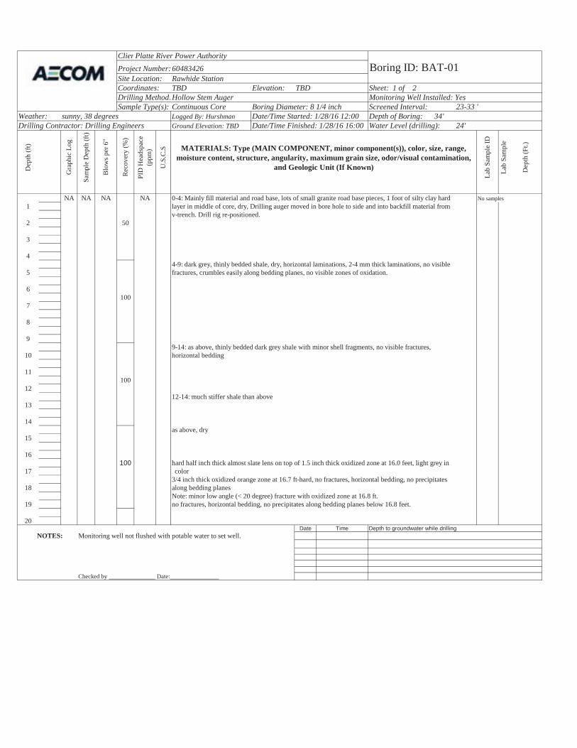
ClienPlatte River Power AuthorityProject Number: 60483426 Boring ID: BAT-01Site Location: Rawhide StationCoordinates: TBD Elevation: TBD Sheet: 1 of 2Drilling Method:Hollow Stem Auger Monitoring Well Installed: YesSample Type(s): Continuous Core Boring Diameter: 8 1/4 inch Screened Interval: 23-33 '
Weather: sunny, 38 degrees Logged By: Hurshman Date/Time Started: 1/28/16 12:00 Depth of Boring: 34'Drilling Contractor: Drilling Engineers Ground Elevation: TBD Date/Time Finished: 1/28/16 16:00 Water Level (drilling): 24'
Dep
th (f
t)
Gra
phic
Log
Sam
ple
Dep
th (f
t)
Rec
over
y (%
)
PID
Hea
dspa
ce
(ppm
)
U.S
.C.S MATERIALS: Type (MAIN COMPONENT, minor component(s)), color, size, range,
moisture content, structure, angularity, maximum grain size, odor/visual contamination, and Geologic Unit (If Known)
Lab
Sam
ple
ID
Lab
Sam
ple
Dep
th (F
t.)
NA NA NA NA 0-4: Mainly fill material and road base, lots of small granite road base pieces, 1 foot of silty clay hard No samples 1 layer in middle of core, dry, Drilling auger moved in bore hole to side and into backfill material from
v-trench. Drill rig re-positioned.2 50
3
44-9: dark grey, thinly bedded shale, dry, horizontal laminations, 2-4 mm thick laminations, no visible
5 fractures, crumbles easily along bedding planes, no visible zones of oxidation.
6100
7
8
99-14: as above, thinly bedded dark grey shale with minor shell fragments, no visible fractures,
10 horizontal bedding
11100
1212-14: much stiffer shale than above
13
14as above, dry
15
16100 hard half inch thick almost slate lens on top of 1.5 inch thick oxidized zone at 16.0 feet, light grey in
17 color3/4 inch thick oxidized orange zone at 16.7 ft-hard, no fractures, horizontal bedding, no precipitates
18 along bedding planesNote: minor low angle (< 20 degree) fracture with oxidized zone at 16.8 ft.
19 no fractures, horizontal bedding, no precipitates along bedding planes below 16.8 feet.
20Date Time Depth to groundwater while drilling
NOTES: Monitoring well not flushed with potable water to set well.
Checked by ________________Date:________________
Blo
ws p
er 6
"
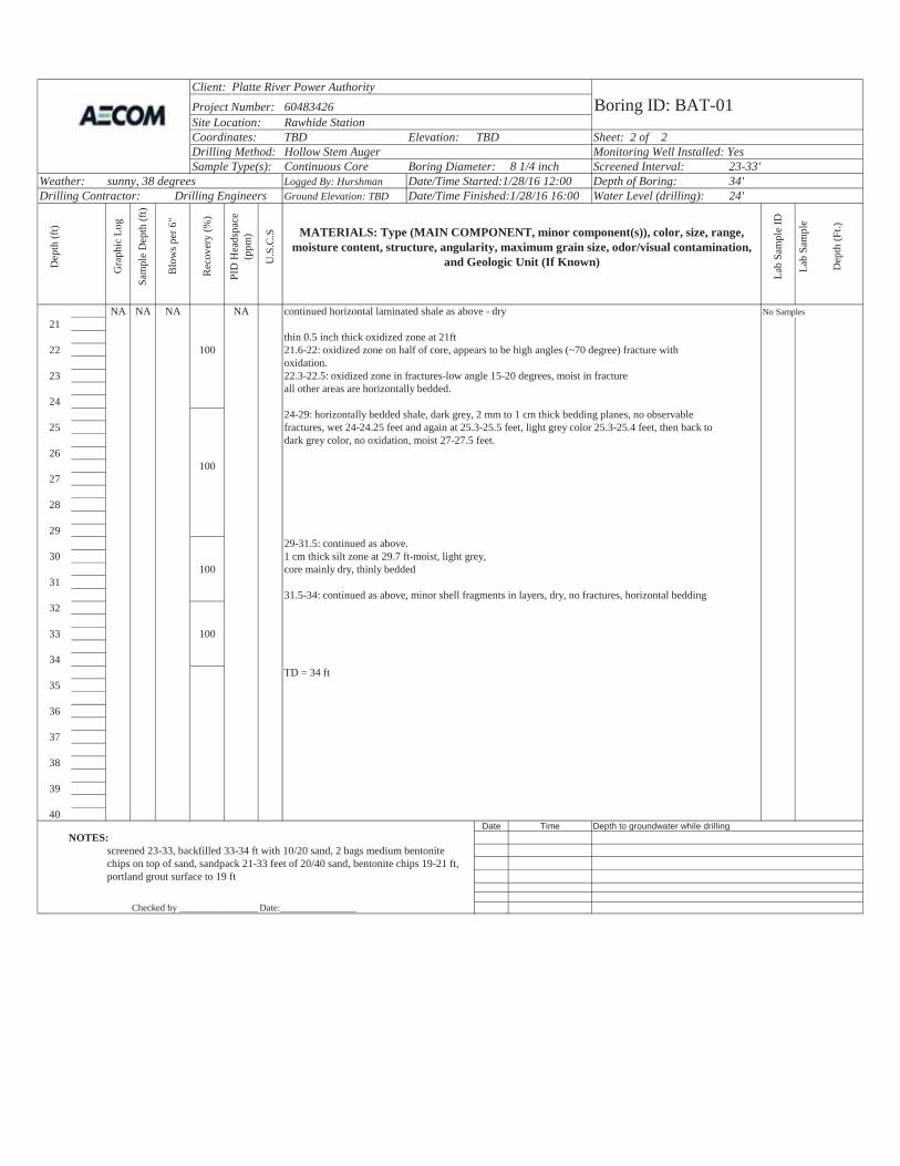
Client: Platte River Power AuthorityProject Number: 60483426 Boring ID: BAT-01Site Location: Rawhide StationCoordinates: TBD Elevation: TBD Sheet: 2 of 2Drilling Method: Hollow Stem Auger Monitoring Well Installed: YesSample Type(s): Continuous Core Boring Diameter: 8 1/4 inch Screened Interval: 23-33'
Weather: sunny, 38 degrees Logged By: Hurshman Date/Time Started:1/28/16 12:00 Depth of Boring: 34'Drilling Contractor: Drilling Engineers Ground Elevation: TBD Date/Time Finished:1/28/16 16:00 Water Level (drilling): 24'
Dep
th (f
t)
Gra
phic
Log
Sam
ple
Dep
th (f
t)
Rec
over
y (%
)
PID
Hea
dspa
ce
(ppm
)
U.S
.C.S MATERIALS: Type (MAIN COMPONENT, minor component(s)), color, size, range,
moisture content, structure, angularity, maximum grain size, odor/visual contamination, and Geologic Unit (If Known)
Lab
Sam
ple
ID
Lab
Sam
ple
Dep
th (F
t.)
NA NA NA NA continued horizontal laminated shale as above - dry No Samples21
thin 0.5 inch thick oxidized zone at 21ft22 100 21.6-22: oxidized zone on half of core, appears to be high angles (~70 degree) fracture with
oxidation.23 22.3-22.5: oxidized zone in fractures-low angle 15-20 degrees, moist in fracture
all other areas are horizontally bedded.24
24-29: horizontally bedded shale, dark grey, 2 mm to 1 cm thick bedding planes, no observable25 fractures, wet 24-24.25 feet and again at 25.3-25.5 feet, light grey color 25.3-25.4 feet, then back to
dark grey color, no oxidation, moist 27-27.5 feet.26
10027
28
2929-31.5: continued as above.
30 1 cm thick silt zone at 29.7 ft-moist, light grey, 100 core mainly dry, thinly bedded
3131.5-34: continued as above, minor shell fragments in layers, dry, no fractures, horizontal bedding
32
33 100
34TD = 34 ft
35
36
37
38
39
40Date Time Depth to groundwater while drilling
NOTES:screened 23-33, backfilled 33-34 ft with 10/20 sand, 2 bags medium bentonite chips on top of sand, sandpack 21-33 feet of 20/40 sand, bentonite chips 19-21 ft, portland grout surface to 19 ft
Checked by _________________Date:________________
Blo
ws p
er 6
"
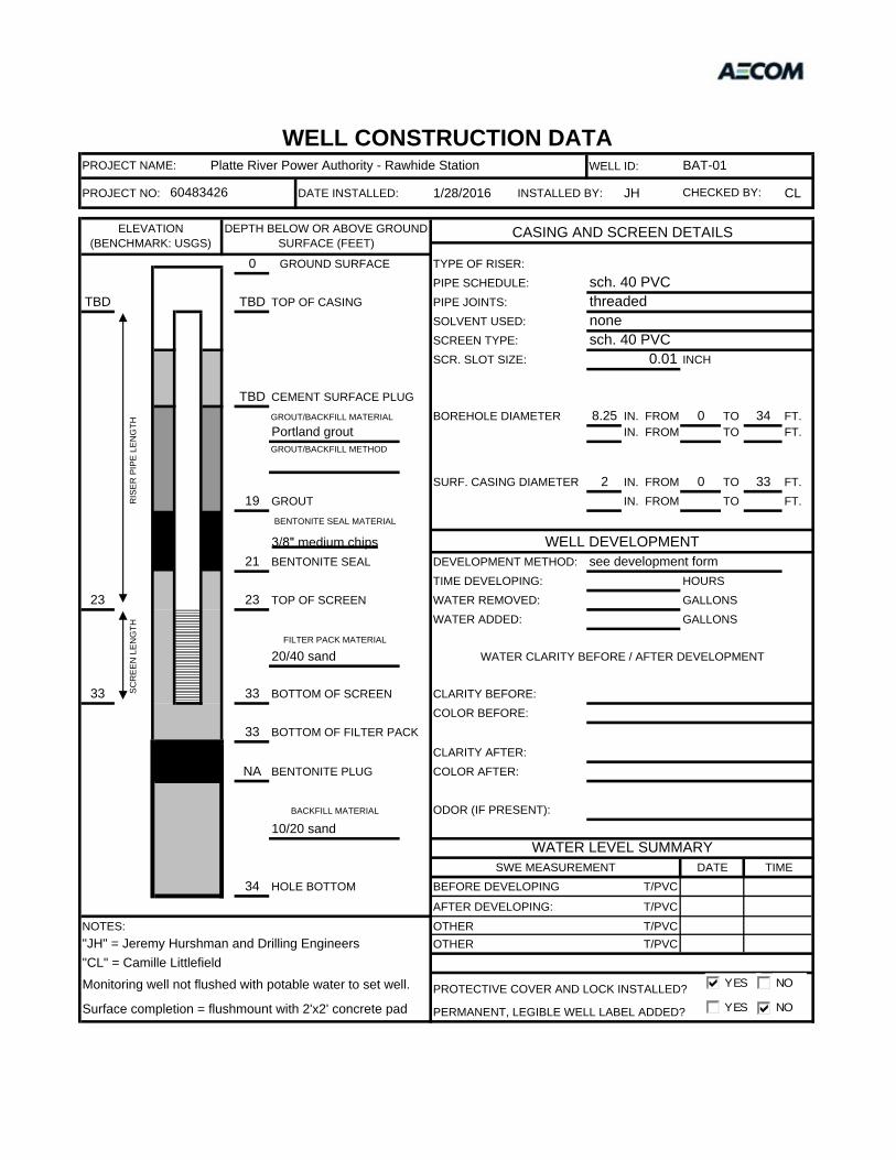
WELL ID:
PROJECT NO: DATE INSTALLED: 1/28/2016 INSTALLED BY: JH CL
PIPE SCHEDULE:TBD TBD PIPE JOINTS:
SOLVENT USED:SCREEN TYPE:SCR. SLOT SIZE: INCH
TBDBOREHOLE DIAMETER 8.25 IN. FROM 0 TO 34 FT.
IN. FROM TO FT.
SURF. CASING DIAMETER 2 IN. FROM 0 TO 33 FT.19 IN. FROM TO FT.
21 DEVELOPMENT METHOD:TIME DEVELOPING: HOURS
23 23 WATER REMOVED: GALLONSWATER ADDED: GALLONS
33 33 CLARITY BEFORE:COLOR BEFORE:
33CLARITY AFTER:
NA COLOR AFTER:
ODOR (IF PRESENT):
34 BEFORE DEVELOPING
AFTER DEVELOPING:
NOTES: OTHEROTHER
PROTECTIVE COVER AND LOCK INSTALLED?
PERMANENT, LEGIBLE WELL LABEL ADDED?Surface completion = flushmount with 2'x2' concrete pad
"JH" = Jeremy Hurshman and Drilling Engineers T/PVC"CL" = Camille Littlefield
Monitoring well not flushed with potable water to set well.
T/PVC
T/PVC
BACKFILL MATERIAL
10/20 sandWATER LEVEL SUMMARY
SWE MEASUREMENT DATE TIMEHOLE BOTTOM T/PVC
BOTTOM OF SCREEN
BOTTOM OF FILTER PACK
BENTONITE PLUG
TOP OF SCREEN
SCR
EEN
LEN
GTH
FILTER PACK MATERIAL
20/40 sand WATER CLARITY BEFORE / AFTER DEVELOPMENT
BENTONITE SEAL MATERIAL
WELL DEVELOPMENT3/8" medium chips BENTONITE SEAL see development form
CEMENT SURFACE PLUGGROUT/BACKFILL MATERIAL
Portland groutGROUT/BACKFILL METHOD
GROUT
sch. 40 PVCTOP OF CASING threaded
RIS
ER P
IPE
LEN
GTH
nonesch. 40 PVC
0.01
ELEVATION (BENCHMARK: USGS)
DEPTH BELOW OR ABOVE GROUND SURFACE (FEET)
CASING AND SCREEN DETAILS
0 GROUND SURFACE TYPE OF RISER:
WELL CONSTRUCTION DATAPROJECT NAME: Platte River Power Authority - Rawhide Station BAT-01
60483426 CHECKED BY:
YES NO
YES NO
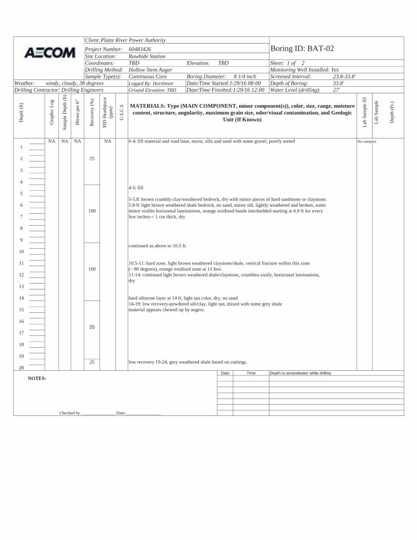
Client:Platte River Power AuthorityProject Number: 60483426 Boring ID: BAT-02Site Location: Rawhide StationCoordinates: TBD Elevation: TBD Sheet: 1 of 2Drilling Method: Hollow Stem Auger Monitoring Well Installed: YesSample Type(s): Continuous Core Boring Diameter: 8 1/4 inch Screened Interval: 23.8-33.8'
Weather: windy, cloudy, 38 degrees Logged By: Hurshman Date/Time Started:1/29/16 08:00 Depth of Boring: 33.8'Drilling Contractor: Drilling Engineers Ground Elevation: TBD Date/Time Finished:1/29/16 12:00 Water Level (drilling): 27'
Dep
th (f
t)
Gra
phic
Log
Sam
ple
Dep
th (f
t)
Rec
over
y (%
)
PID
Hea
dspa
ce
(ppm
)
U.S
.C.S MATERIALS: Type (MAIN COMPONENT, minor component(s)), color, size, range, moisture
content, structure, angularity, maximum grain size, odor/visual contamination, and Geologic Unit (If Known)
Lab
Sam
ple
ID
Lab
Sam
ple
Dep
th (F
t.)
NA NA NA NA 0-4: fill material and road base, moist, silts and sand with some gravel, poorly sorted No samples 1
2 25
3
44-5: fill
55-5.8: brown crumbly clay/weathered bedrock, dry with minor pieces of hard sandstone or claystone.
6 5.8-9: light brown weathered shale bedrock, no sand, minor silt, lightly weathered and broken, some100 minor visible horizontal laminations, orange oxidized bands interbedded starting at 6.9 ft for every
7 few inches-< 1 cm thick, dry
8
9continued as above to 10.5 ft.
10
11 10.5-11: hard zone, light brown weathered claystone/shale, vertical fracture within this zone100 (~ 80 degrees), orange oxidized zone at 11 feet.
12 11-14: continued light brown weathered shale/claystone, crumbles easily, horizontal laminations, dry
13
14 hard siltstone layer at 14 ft, light tan color, dry, no sand14-19: low recovery-powdered silt/clay, light tan, mixed with some grey shale
15 material appears chewed up by augers.
1625
17
18
1925 low recovery 19-24, grey weathered shale based on cuttings.
20Date Time Depth to groundwater while drilling
NOTES:
Checked by ________________Date:________________
Blo
ws p
er 6
"
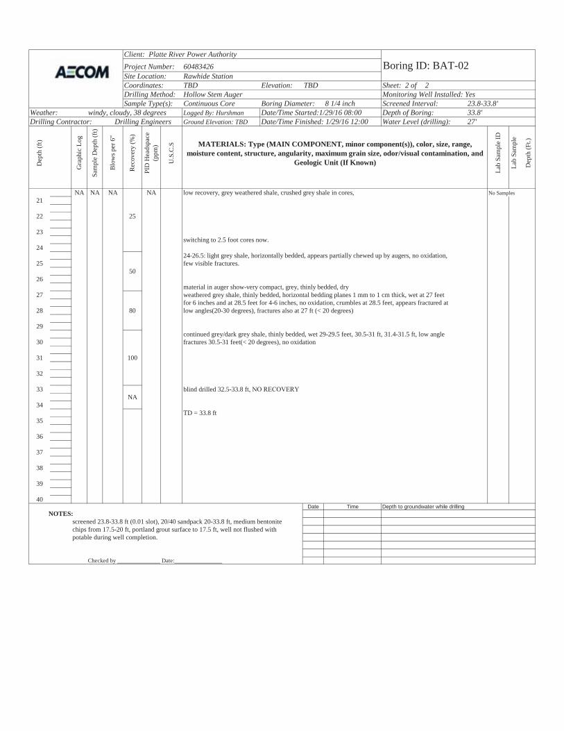
Client: Platte River Power AuthorityProject Number: 60483426 Boring ID: BAT-02Site Location: Rawhide StationCoordinates: TBD Elevation: TBD Sheet: 2 of 2Drilling Method: Hollow Stem Auger Monitoring Well Installed: YesSample Type(s): Continuous Core Boring Diameter: 8 1/4 inch Screened Interval: 23.8-33.8'
Weather: windy, cloudy, 38 degrees Logged By: Hurshman Date/Time Started:1/29/16 08:00 Depth of Boring: 33.8'Drilling Contractor: Drilling Engineers Ground Elevation: TBD Date/Time Finished: 1/29/16 12:00 Water Level (drilling): 27'
Dep
th (f
t)
Gra
phic
Log
Sam
ple
Dep
th (f
t)
Rec
over
y (%
)
PID
Hea
dspa
ce
(ppm
)
U.S
.C.S MATERIALS: Type (MAIN COMPONENT, minor component(s)), color, size, range,
moisture content, structure, angularity, maximum grain size, odor/visual contamination, and Geologic Unit (If Known)
Lab
Sam
ple
ID
Lab
Sam
ple
Dep
th (F
t.)
NA NA NA NA low recovery, grey weathered shale, crushed grey shale in cores, No Samples21
22 25
23switching to 2.5 foot cores now.
2424-26.5: light grey shale, horizontally bedded, appears partially chewed up by augers, no oxidation,
25 few visible fractures.50
26material in auger show-very compact, grey, thinly bedded, dry
27 weathered grey shale, thinly bedded, horizontal bedding planes 1 mm to 1 cm thick, wet at 27 feet for 6 inches and at 28.5 feet for 4-6 inches, no oxidation, crumbles at 28.5 feet, appears fractured at
28 80 low angles(20-30 degrees), fractures also at 27 ft (< 20 degrees)
29continued grey/dark grey shale, thinly bedded, wet 29-29.5 feet, 30.5-31 ft, 31.4-31.5 ft, low angle
30 fractures 30.5-31 feet(< 20 degrees), no oxidation
31 100
32
33 blind drilled 32.5-33.8 ftNA
34TD = 33.8 ft
35
36
37
38
39
40Date Time Depth to groundwater while drilling
NOTES:screened 23.8-33.8 ft (0.01 slot), 20/40 sandpack 20-33.8 ft, medium bentonite chips from 17.5-20 ft, portland grout surface to 17.5 ft, well not flushed with potable during well completion.
Checked by _______________Date:________________
Blo
ws p
er 6
"

WELL ID:
PROJECT NO: DATE INSTALLED: 1/29/2016 INSTALLED BY: JH CL
PIPE SCHEDULE:TBD TBD PIPE JOINTS:
SOLVENT USED:SCREEN TYPE:SCR. SLOT SIZE: INCH
TBDBOREHOLE DIAMETER 8.25 IN. FROM 0 TO 33.8 FT.
IN. FROM TO FT.
SURF. CASING DIAMETER 2 IN. FROM 0 TO 33.8 FT.17.5 IN. FROM TO FT.
20 DEVELOPMENT METHOD:TIME DEVELOPING: HOURS
23.8 23.8 WATER REMOVED: GALLONSWATER ADDED: GALLONS
33.8 33.8 CLARITY BEFORE:COLOR BEFORE:
33.8CLARITY AFTER:
NA COLOR AFTER:
ODOR (IF PRESENT):
33.8 BEFORE DEVELOPING
AFTER DEVELOPING:
NOTES: OTHEROTHER
PROTECTIVE COVER AND LOCK INSTALLED?
PERMANENT, LEGIBLE WELL LABEL ADDED?Surface completion = flushmount with 2'x2' concrete pad
"JH" = Jeremy Hurshman and Drilling Engineers T/PVC"CL" = Camille Littlefield
Monitoring well not flushed with potable water to set well.
T/PVC
T/PVC
BACKFILL MATERIAL
NAWATER LEVEL SUMMARY
SWE MEASUREMENT DATE TIMEHOLE BOTTOM T/PVC
BOTTOM OF SCREEN
BOTTOM OF FILTER PACK
BENTONITE PLUG
TOP OF SCREEN
SCR
EEN
LEN
GTH
FILTER PACK MATERIAL
20/40 sand WATER CLARITY BEFORE / AFTER DEVELOPMENT
GROUTBENTONITE SEAL MATERIAL
3/8" medium chips WELL DEVELOPMENTBENTONITE SEAL see development form
CEMENT SURFACE PLUGGROUT/BACKFILL MATERIAL
Portland groutGROUT/BACKFILL METHOD
sch. 40 PVCTOP OF CASING threaded
RIS
ER P
IPE
LEN
GTH
nonesch. 40 PVC
0.01
ELEVATION (BENCHMARK: USGS)
DEPTH BELOW OR ABOVE GROUND SURFACE (FEET)
CASING AND SCREEN DETAILS
0 GROUND SURFACE TYPE OF RISER:
WELL CONSTRUCTION DATAPROJECT NAME: Platte River Power Authority - Rawhide Station BAT-02
60483426 CHECKED BY:
YES NO
YES NO
Client:Platte River Power Authority
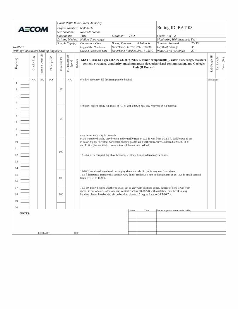
Project Number: 60483426 Boring ID: BAT-03Site Location: Rawhide StationCoordinates: TBD Elevation: TBD Sheet: 1 of 2Drilling Method: Hollow Stem Auger Monitoring Well Installed: YesSample Type(s): Continuous Core Boring Diameter: 8 1/4 inch Screened Interval: 26-36'
Weather: Logged By: Hurshman Date/Time Started: 2/4/16 08:00 Depth of Boring: 36'Drilling Contractor: Drilling Engineers Ground Elevation: TBD Date/Time Finished:2/4/16 15:30 Water Level (drilling): 27'
Dep
th (f
t)
Gra
phic
Log
Sam
ple
Dep
th (f
t)
Rec
over
y (%
)
PID
Hea
dspa
ce
(ppm
)
U.S
.C.S MATERIALS: Type (MAIN COMPONENT, minor component(s)), color, size, range, moisture
content, structure, angularity, maximum grain size, odor/visual contamination, and Geologic Unit (If Known)
Lab
Sam
ple
ID
Lab
Sam
ple
Dep
th (F
t.)
NA NA NA NA 0-4: low recovery, fill dirt from pothole backfill No samples 1
2 25
3
44-9: dark brown sandy fill, moist at 7.5 ft, wet at 8.6 ft bgs, low recovery in fill material
5
625
7
8
9 note: water very silty in borehole9-14: weathered shale, very broken and crumbly from 9-12.5 ft, wet from 9-12.5 ft, dark brown to tan
10 in color, highly fractured, horizontal bedding planes with vertical fractures, oxidized at 9.5 ft, 11 ft, and 11.6 ft (2-4 cm thick zones), minor silt lenses interbedded.
11100
12 12.5-14: very compact dry shale bedrock, weathered, mottled tan to grey colors.
13
1414-16.2: continued weathered tan to grey shale, outside of core is very wet from above,
15 15.8 ft-horizontal fracture that appears wet, thinly bedded 2-4 mm bedding planes at 16-16.5 ft, small vertical100 fracture 15.8 to 15.9 ft.
16
17 16.5-19: thinly bedded weathered shale, tan to grey with oxidized zones, outside of core is wet from above, inside of core is dry to moist, vertical fracture 18-18.5 ft with oxidation, core breaks along
18 100 bedding planes, interbedded silt on bedding planes, 15 degree fracture 16.5-16.7 ft.
19
20Date Time Depth to groundwater while drilling
NOTES:
Checked by ____________________Date:________________
Blo
ws p
er 6
"
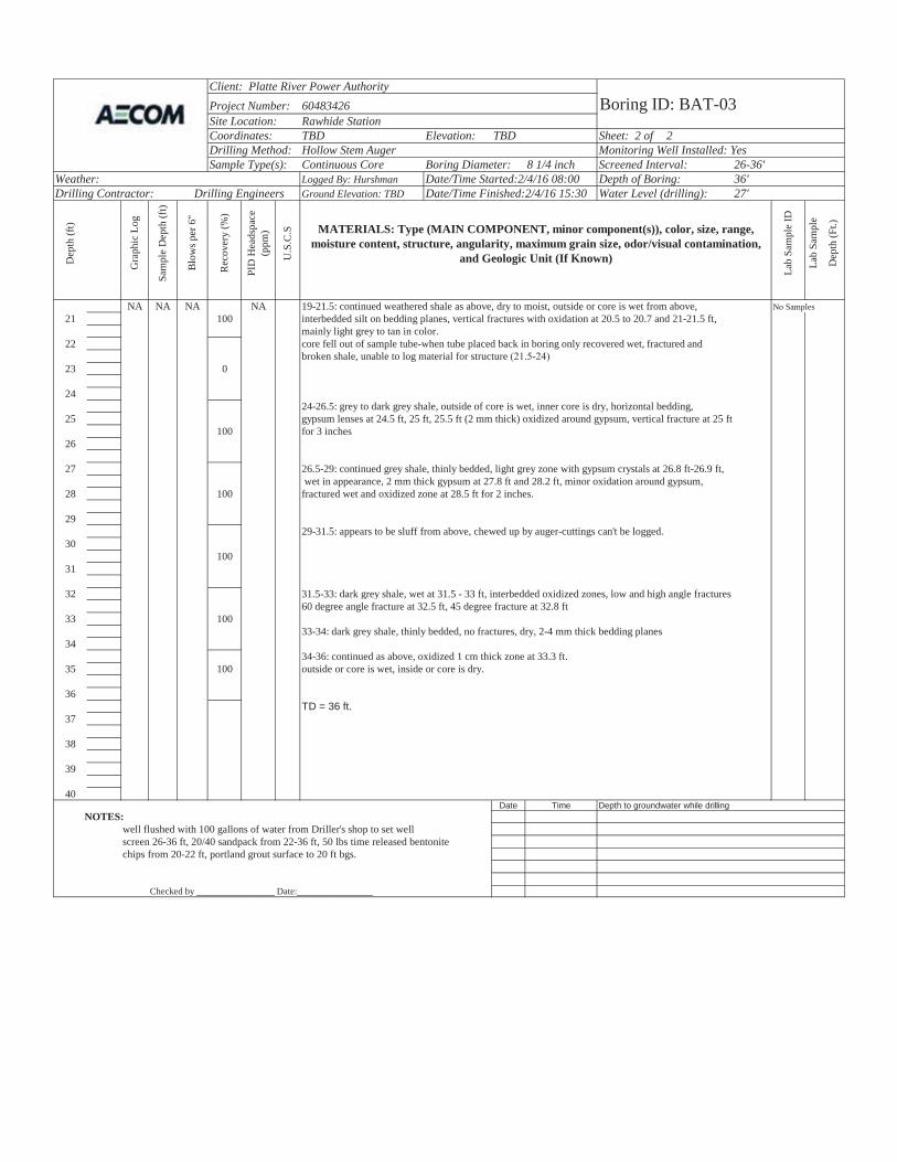
Client: Platte River Power AuthorityProject Number: 60483426 Boring ID: BAT-03Site Location: Rawhide StationCoordinates: TBD Elevation: TBD Sheet: 2 of 2Drilling Method: Hollow Stem Auger Monitoring Well Installed: YesSample Type(s): Continuous Core Boring Diameter: 8 1/4 inch Screened Interval: 26-36'
Weather: Logged By: Hurshman Date/Time Started:2/4/16 08:00 Depth of Boring: 36'Drilling Contractor: Drilling Engineers Ground Elevation: TBD Date/Time Finished:2/4/16 15:30 Water Level (drilling): 27'
Dep
th (f
t)
Gra
phic
Log
Sam
ple
Dep
th (f
t)
Rec
over
y (%
)
PID
Hea
dspa
ce
(ppm
)
U.S
.C.S MATERIALS: Type (MAIN COMPONENT, minor component(s)), color, size, range,
moisture content, structure, angularity, maximum grain size, odor/visual contamination, and Geologic Unit (If Known)
Lab
Sam
ple
ID
Lab
Sam
ple
Dep
th (F
t.)
NA NA NA NA No Samples21 100
22
19-21.5: continued weathered shale as above, dry to moist, outside or core is wet from above,interbedded silt on bedding planes, vertical fractures with oxidation at 20.5 to 20.7 and 21-21.5 ft,mainly light grey to tan in color.core fell out of sample tube-when tube placed back in boring only recovered wet, fractured and broken shale, unable to log material for structure
23 0
2424-26.5: grey to dark grey shale, outside of core is wet, inner core is dry, horizontal bedding,
25 gypsum lenses at 24.5 ft, 25 ft, 25.5 ft (2 mm thick) oxidized around gypsum, vertical fracture at 25 ft100 for 3 inches
26
27 26.5-29: continued grey shale, thinly bedded, light grey zone with gypsum crystals at 26.8 ft-26.9 ft, wet in appearance, 2 mm thick gypsum at 27.8 ft and 28.2 ft, minor oxidation around gypsum,
28 100 fractured wet and oxidized zone at 28.5 ft for 2 inches.
2929-31.5: appears to be sluff from above, chewed up by auger-cuttings can't be logged.
30100
31
32 31.5-33: dark grey shale, wet at 31.5 - 33 ft, interbedded oxidized zones, low and high angle fractures60 degree angle fracture at 32.5 ft, 45 degree fracture at 32.8 ft
33 10033-34: dark grey shale, thinly bedded, no fractures, dry, 2-4 mm thick bedding planes
3434-36: continued as above, oxidized 1 cm thick zone at 33.3 ft.
35 100 outside or core is wet, inside or core is dry.
36TD = 36 ft.
37
38
39
40Date Time Depth to groundwater while drilling
NOTES:well flushed with 100 gallons of water from Driller's shop to set wellscreen 26-36 ft, 20/40 sandpack from 22-36 ft, 50 lbs time released bentonite chips from 20-22 ft, portland grout surface to 20 ft bgs.
Checked by _________________Date:________________
Blo
ws p
er 6
"

WELL ID:
PROJECT NO: DATE INSTALLED: 2/4/2016 INSTALLED BY: JH CL
PIPE SCHEDULE:TBD TBD PIPE JOINTS:
SOLVENT USED:SCREEN TYPE:SCR. SLOT SIZE: INCH
TBDBOREHOLE DIAMETER 8.25 IN. FROM 0 TO 36 FT.
IN. FROM TO FT.
SURF. CASING DIAMETER 2 IN. FROM 0 TO 36 FT.20 IN. FROM TO FT.
22 DEVELOPMENT METHOD:TIME DEVELOPING: HOURS
26 26 WATER REMOVED: GALLONSWATER ADDED: GALLONS
36 36 CLARITY BEFORE:COLOR BEFORE:
36CLARITY AFTER:
NA COLOR AFTER:
ODOR (IF PRESENT):
36 BEFORE DEVELOPING
AFTER DEVELOPING:
NOTES: OTHEROTHER
PROTECTIVE COVER AND LOCK INSTALLED?
PERMANENT, LEGIBLE WELL LABEL ADDED?
Flushed with 100 gallons of water from Driller's shop to set well. Surface completion = flushmount with 2'x2' concrete pad
"JH" = Jeremy Hurshman and Drilling Engineers T/PVC"CL" = Camille Littlefield
T/PVC
T/PVC
BACKFILL MATERIAL
NAWATER LEVEL SUMMARY
SWE MEASUREMENT DATE TIMEHOLE BOTTOM T/PVC
BOTTOM OF SCREEN
BOTTOM OF FILTER PACK
BENTONITE PLUG
TOP OF SCREEN
SCR
EEN
LEN
GTH
FILTER PACK MATERIAL
20/40 sand WATER CLARITY BEFORE / AFTER DEVELOPMENT
GROUTBENTONITE SEAL MATERIAL
time-released pellets WELL DEVELOPMENTBENTONITE SEAL see development form
CEMENT SURFACE PLUGGROUT/BACKFILL MATERIAL
Portland groutGROUT/BACKFILL METHOD
sch. 40 PVCTOP OF CASING threaded
RIS
ER P
IPE
LEN
GTH
nonesch. 40 PVC
0.01
ELEVATION (BENCHMARK: USGS)
DEPTH BELOW OR ABOVE GROUND SURFACE (FEET)
CASING AND SCREEN DETAILS
0 GROUND SURFACE TYPE OF RISER:
WELL CONSTRUCTION DATAPROJECT NAME: Platte River Power Authority - Rawhide Station BAT-03
60483426 CHECKED BY:
YES NO
YES NO
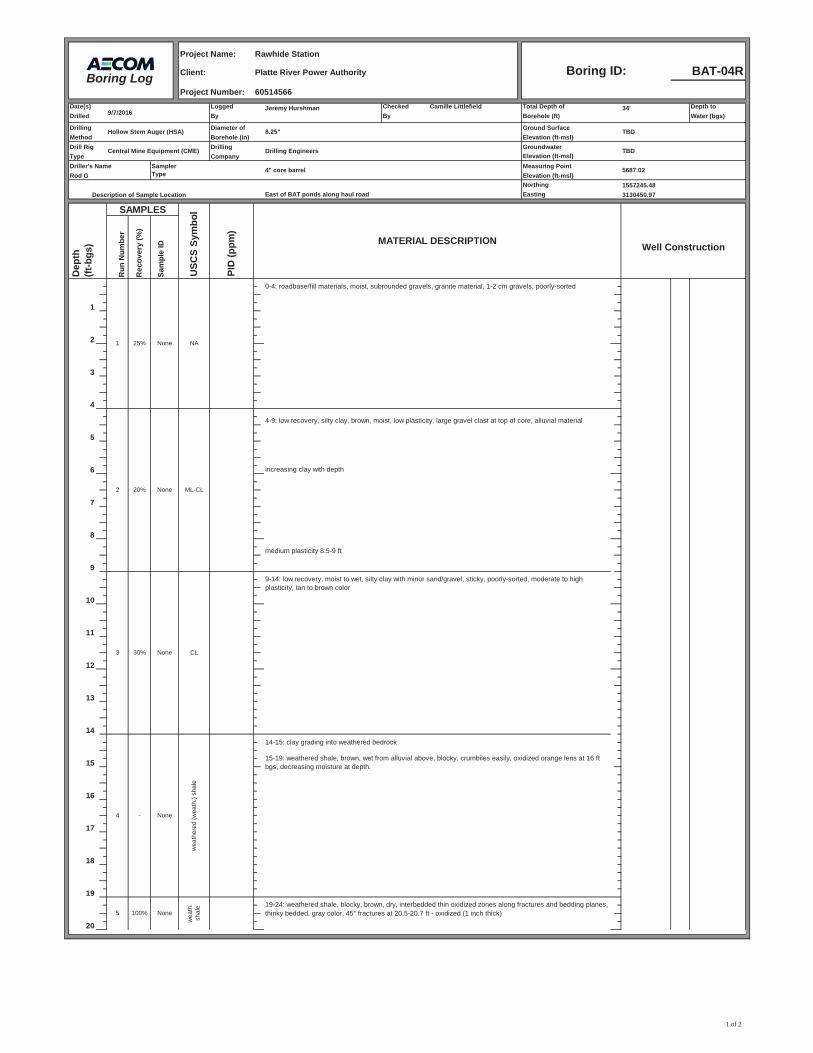
Project Name:
Client: BAT-04RProject Number:
Date(s) Logged Jeremy Hurshman Checked Camille Littlefield Total Depth of 34' Depth toDrilled By By Borehole (ft) Water (bgs)
Drilling Diameter of Ground SurfaceMethod Borehole (in) Elevation (ft-msl)Drill Rig Drilling GroundwaterType Company Elevation (ft-msl)Driller's Name Measuring Point
Elevation (ft-msl)Northing 1557245.48
East of BAT ponds along haul road Easting 3130450.97
Dep
th
(ft
-bgs
)
Run
Num
ber
Rec
over
y (%
)
Sam
ple
ID Well Construction
1
2
3
4
5
6 increasing clay with depth
7
8
medium plasticity 8.5-9 ft
9
10
11
12
13
14
15
16
17
18
19
20
9-14: low recovery, moist to wet, silty clay with minor sand/gravel, sticky, poorly-sorted, moderate to high plasticity, tan to brown color
4-9: low recovery, silty clay, brown, moist, low plasticity, large gravel clast at top of core, alluvial material
Drilling Engineers
4" core barrelSamplerType 5687.02
2 20% None ML-CL
3 30% None CL
1 25% None NA
0-4: roadbase/fill materials, moist, subrounded gravels, granite material, 1-2 cm gravels, poorly-sorted
wea
th.
shal
e
5 100% None19-24: weathered shale, blocky, brown, dry, interbedded thin oxidized zones along fractures and bedding planes, thinky bedded, gray color, 45° fractures at 20.5-20.7 ft - oxidized (1 inch thick)
Rawhide Station
Platte River Power Authority
SAMPLES
Hollow Stem Auger (HSA)
60514566
9/7/2016
Central Mine Equipment (CME)
Rod G
15-19: weathered shale, brown, wet from alluvial above, blocky, crumbiles easily, oxidized orange lens at 16 ft bgs, decreasing moisture at depth.
TBD
MATERIAL DESCRIPTIONPI
D (p
pm)
Description of Sample Location
4 - None
wea
ther
ed (w
eath
.) sh
ale
Boring ID:
8.25"
TBD
USC
S Sy
mbo
l
Boring Log
14-15: clay grading into weathered bedrock
1 of 2
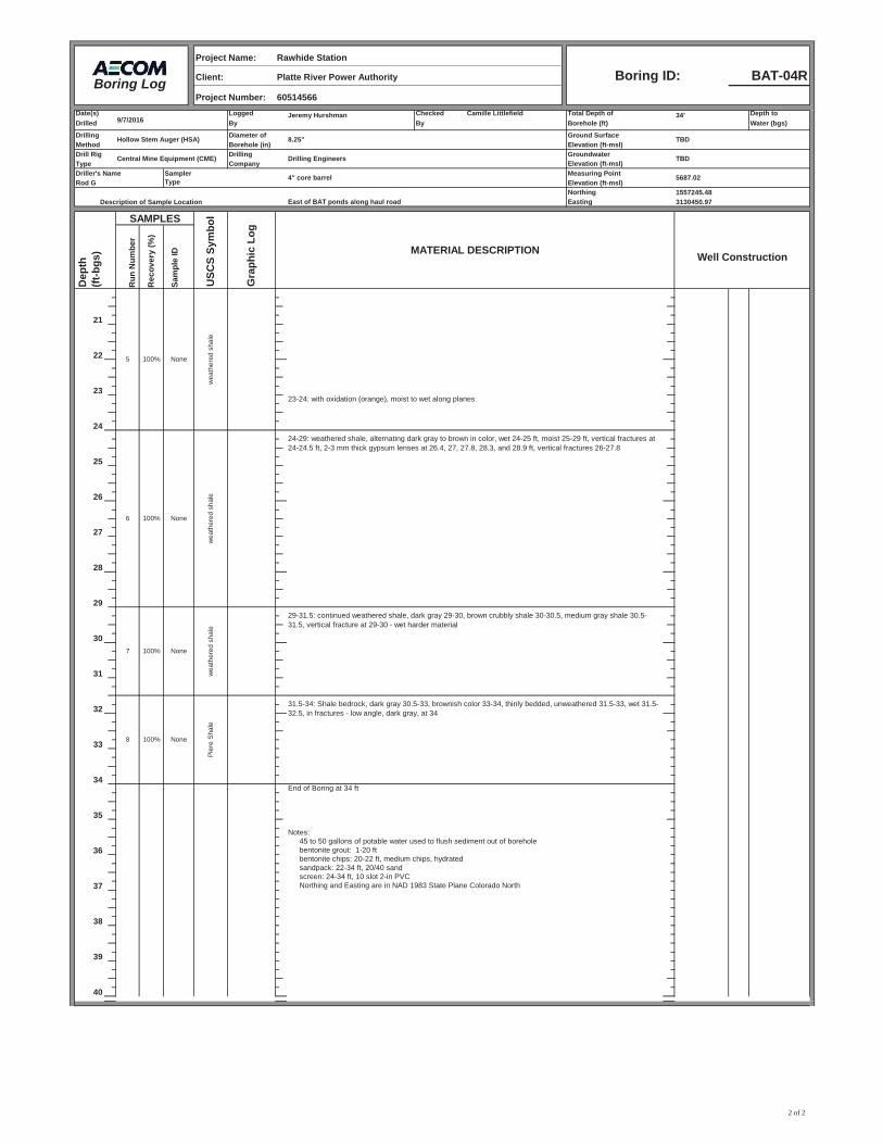
Project Name:
Client: BAT-04RProject Number:
Date(s) Logged Jeremy Hurshman Checked Camille Littlefield Total Depth of 34' Depth toDrilled By By Borehole (ft) Water (bgs)
Drilling Diameter of Ground SurfaceMethod Borehole (in) Elevation (ft-msl)Drill Rig Drilling GroundwaterType Company Elevation (ft-msl)Driller's Name Measuring Point
Elevation (ft-msl)Northing 1557245.48
East of BAT ponds along haul road Easting 3130450.97
Dep
th
(ft
-bgs
)
Run
Num
ber
Rec
over
y (%
)
Sam
ple
ID Well Construction
21
22
2323-24: with oxidation (orange), moist to wet along planes
24
25
26
27
28
29
30
31
32
33
34End of Boring at 34 ft
35
Notes: 45 to 50 gallons of potable water used to flush sediment out of borehole
36 bentonite grout: 1-20 ftbentonite chips: 20-22 ft, medium chips, hydratedsandpack: 22-34 ft, 20/40 sandscreen: 24-34 ft, 10 slot 2-in PVC
37 Northing and Easting are in NAD 1983 State Plane Colorado North
38
39
40
100% None
wea
ther
ed s
hale
60514566
Drilling Engineers
100% None
wea
ther
ed s
hale
29-31.5: continued weathered shale, dark gray 29-30, brown crubbly shale 30-30.5, medium gray shale 30.5-31.5, vertical fracture at 29-30 - wet harder material
5
100% None
31.5-34: Shale bedrock, dark gray 30.5-33, brownish color 33-34, thinly bedded, unweathered 31.5-33, wet 31.5-32.5, in fractures - low angle, dark gray, at 34
6 100% None
wea
ther
ed s
hale
24-29: weathered shale, alternating dark gray to brown in color, wet 24-25 ft, moist 25-29 ft, vertical fractures at 24-24.5 ft, 2-3 mm thick gypsum lenses at 26.4, 27, 27.8, 28.3, and 28.9 ft, vertical fractures 26-27.8
7
Description of Sample Location
SAMPLES
MATERIAL DESCRIPTION
USC
S Sy
mbo
l
Gra
phic
Log
Pie
re S
hale
8
9/7/2016
Hollow Stem Auger (HSA) 8.25" TBD
Central Mine Equipment (CME) TBD
AECOM Boring Log
5687.02Rod G
Rawhide Station
Platte River Power Authority Boring ID:
SamplerType 4" core barrel
2 of 2

WELL ID:
PROJECT NO: DATE INSTALLED: 9/7/2016 INSTALLED BY: JH CL
PIPE SCHEDULE:~2.5 TBD PIPE JOINTS:
SOLVENT USED:0 SCREEN TYPE:
SCR. SLOT SIZE: INCH
1BOREHOLE DIAMETER 8.25 IN. FROM 0 TO 34 FT.
IN. FROM TO FT.
SURF. CASING DIAMETER 2 IN. FROM 0 TO 34 FT.20 IN. FROM TO FT.
22 DEVELOPMENT METHOD:TIME DEVELOPING: HOURS
24 24 WATER REMOVED: GALLONSWATER ADDED: GALLONS
34 34 CLARITY BEFORE:COLOR BEFORE:
34CLARITY AFTER:
NA COLOR AFTER:
ODOR (IF PRESENT):
34 BEFORE DEVELOPING
AFTER DEVELOPING:
NOTES: OTHEROTHER
PROTECTIVE COVER AND LOCK INSTALLED?
PERMANENT, LEGIBLE WELL LABEL ADDED?
GROUND SURFACE
WELL CONSTRUCTION DATAPROJECT NAME: Platte River Power Authority - Rawhide Station BAT-04R
60514655 CHECKED BY:
ELEVATION (BENCHMARK: USGS)
DEPTH BELOW OR ABOVE GROUND SURFACE (FEET)
CASING AND SCREEN DETAILS
TYPE OF RISER:sch. 40 PVC
TOP OF CASING threaded
RIS
ER P
IPE
LEN
GTH
nonesch. 40 PVC
0.01
CEMENT SURFACE PLUGGROUT/BACKFILL MATERIAL
Portland groutGROUT/BACKFILL METHOD
GROUTBENTONITE SEAL MATERIAL
3/8" chips WELL DEVELOPMENTBENTONITE SEAL see development form
TOP OF SCREEN
SCR
EEN
LEN
GTH
FILTER PACK MATERIAL
20/40 sand WATER CLARITY BEFORE / AFTER DEVELOPMENT
BOTTOM OF SCREEN
HOLE BOTTOM T/PVC
BOTTOM OF FILTER PACK
BENTONITE PLUG
BACKFILL MATERIAL
NAWATER LEVEL SUMMARY
SWE MEASUREMENT DATE TIME
T/PVC
T/PVC
Surface completion = stickup with 3 bollard posts
"JH" = Jeremy Hurshman and Drilling Engineers T/PVC"CL" = Camille Littlefield
Hydrated bentonite chips were used for seal. YES NO
YES NO
Client:Platte River Power Authority
Project Number: 60483426 Boring ID: BAT-05Site Location: Rawhide StationCoordinates: TBD Elevation: TBD Sheet: 1 of 2Drilling Method: Hollow Stem Auger Monitoring Well Installed: YesSample Type(s): Continuous Core Boring Diame8 1/4 inch Screened Interval: 23-38'
Weather: sun, 30 degrees Logged By: Hurshman Date/Time Started: 1/26/16 14:00 Depth of Boring: 39'Drilling Contractor: Drilling Engineers Ground Elevation: TBD Date/Time Finished:1/27/16 12:00 Water Level (drilling): 24'
Dep
th (f
t)
Gra
phic
Log
Sam
ple
Dep
th (f
t)
Rec
over
y (%
)
PID
Hea
dspa
ce
(ppm
)
U.S
.C.S MATERIALS: Type (MAIN COMPONENT, minor component(s)), color, size, range,
moisture content, structure, angularity, maximum grain size, odor/visual contamination, and Geologic Unit (If Known)
Lab
Sam
ple
ID
Lab
Sam
ple
Dep
th (F
t.)
NA NA NA NA No samples 1
0-.5 ft: pothole fill dirt0.5-4: little recovery, mainly fill material/road base, silty sand with clay, moist, angular clasts, poorly sorted, stiff where clay is present.
2 30
3
44-7: no recovery
5
640
77-8: silty sand, brown, moist to wet, poorly sorted, little clay, very fine to medium sand, may be fill
88-9: weathered Pierre Shale bedrock, light brown, dry, crumbles easily, horizontal laminations,
9 slightly micaceous, vertical fracture at 9 ft with oxidationcontinued as above, wet 9-9.5 ft, moist to 10 ft,
10 thinly laminated shale, dry at 10, mottled lightly brown, dark grey and orange colors, laminations2-4 mm thick to 12 feet,
11100
1212-14: thicker laminated shale(1-2 cm), blocky at 13 ft, no major fractures,
13
14contained as above to 19 ft, thinly (2mm to 1 cm) laminated shale, dry,
15 dark brown, minor orange oxide mottling at 15 feet for 3 inches
16100
17
1818: 0.5-1 cm thick white gypsum lenses interbedded to 18.5 ft, horizontal lenses, orange oxide
19 staining at 19 ft, dry
20Date Time Depth to groundwater while drilling
NOTES:
Checked by _______________________Date:________________
Blo
ws p
er 6
"
Client: Platte River Power Authority
Project Number: 60483426 Boring ID: BAT-05Site Location: Rawhide StationCoordinates: TBD Elevation: TBD Sheet: 2 of 2Drilling Method: Hollow Stem Auger Monitoring Well Installed: YesSample Type(s): Continuous Core Boring Diameter: 8 1/4 inch Screened Interval: 23-38'
Weather: sun, 30 degrees Logged By: Hurshman Date/Time Started: 1/26/16 14:00 Depth of Boring: 39'Drilling Contractor: Drilling Engineers Ground Elevation: TBD Date/Time Finished: 1/27/16 12:00 Water Level (drilling): 24'
Dep
th (f
t)
Gra
phic
Log
Sam
ple
Dep
th (f
t)
Rec
over
y (%
)
PID
Hea
dspa
ce
(ppm
)
U.S
.C.S MATERIALS: Type (MAIN COMPONENT, minor component(s)), color, size, range, moisture
content, structure, angularity, maximum grain size, odor/visual contamination, and Geologic Unit (If Known)
Lab
Sam
ple
ID
Lab
Sam
ple
Dep
th (F
t.)
NA NA NA NA continued as above to 22 ft No Samples21 gypsum lenses at 20.7 to 20.9 ft-1 cm thick, dry
22 10022-24: very hard more compact shale, less visible laminations, dark grey, gypsum lenses at 22.5 and
23 23.7 ft-0.5 cm thick lenses, minor orange oxide stain near gypsum, dry
24thinly bedded shale, horizontal laminations approximately 1 mm to 3 mm thick, alternating brown and
25 grey colors from 24-25.6 ft, 2 inch brown to 2 inch grey color zones, dark grey from 25.6 to 29 feet.wet 24-24.3 ft then dry, gypsum lens at 24.6 ft (2 mm thick)oxidized at 26.3 ft (1 cm thick)
26100
27
28
29thinly bedded dark grey shale, dry, 1-3 mm thick bedding planes, no visible fractures
30
31100
32
3333: 1 cm thick bedding planes for 6 inches.
34thinly bedded dark grey shale, horizontal bedding planes, 1-2mm thick beds up to 1 cm thick, no
35 oxidation, appears wet 34-37 ft between bedding planes, dry 37-39 ft.
36100
37
38
39TD = 39 feet
40Date Time Depth to groundwater while drilling
NOTES:well drilled to 34 ft on 1/26/16. augers left in ground and then drilled to 39 ft on 1/27/16. water in borehole on 1/27/16 10 ft bgs.casing flushed with water before setting well due to silty water (150 gallons used)screened 23-38 ft, 20/ sandpack from 21-39 ft, Cetco time released 1/4 inch pellets19-21 ft, portland grout 1-19 ft.
Checked by _______________________Date:________________
Blo
ws p
er 6
"
WELL ID:
PROJECT NO: DATE INSTALLED: INSTALLED BY: JH CL
PIPE SCHEDULE:TBD TBD PIPE JOINTS:
SOLVENT USED:SCREEN TYPE:SCR. SLOT SIZE: INCH
1BOREHOLE DIAMETER 8.25 IN. FROM 0 TO 39 FT.
IN. FROM TO FT.
SURF. CASING DIAMETER 2 IN. FROM 0 TO 38 FT.19 IN. FROM TO FT.
21 DEVELOPMENT METHOD:TIME DEVELOPING: HOURS
23 23 WATER REMOVED: GALLONSWATER ADDED: GALLONS
38 38 CLARITY BEFORE:COLOR BEFORE:
39CLARITY AFTER:
NA COLOR AFTER:
ODOR (IF PRESENT):
39 BEFORE DEVELOPING
AFTER DEVELOPING:
NOTES: OTHEROTHER
PROTECTIVE COVER AND LOCK INSTALLED?
PERMANENT, LEGIBLE WELL LABEL ADDED?
T/PVC
Casing flushed with water before setting well due to silty water (150 gallons used). Surface completion = flushmount with 2'x2' concrete pad
"JH" = Jeremy Hurshman and Drilling Engineers T/PVC"CL" = Camille Littlefield
T/PVC
BACKFILL MATERIAL
NAWATER LEVEL SUMMARY
SWE MEASUREMENT DATE TIMEHOLE BOTTOM T/PVC
BOTTOM OF FILTER PACK
BENTONITE PLUG
TOP OF SCREEN
SCR
EEN
LEN
GTH
FILTER PACK MATERIAL
20/40 sand WATER CLARITY BEFORE / AFTER DEVELOPMENT
BOTTOM OF SCREEN
GROUTBENTONITE SEAL MATERIAL
Time-released pellets WELL DEVELOPMENTBENTONITE SEAL see development form
CEMENT SURFACE PLUGGROUT/BACKFILL MATERIAL
Portland groutGROUT/BACKFILL METHOD
sch. 40 PVCTOP OF CASING threaded
RIS
ER P
IPE
LEN
GTH
nonesch. 40 PVC
0.01
ELEVATION (BENCHMARK: USGS)
DEPTH BELOW OR ABOVE GROUND SURFACE (FEET)
CASING AND SCREEN DETAILS
0 GROUND SURFACE TYPE OF RISER:
WELL CONSTRUCTION DATAPROJECT NAME: Platte River Power Authority - Rawhide Station BAT-05
60483426 CHECKED BY:1/26/16-1/27/16
YES NO
YES NO
Client:Platte River Power AuthorityProject Number: 60483426 Boring ID: BAT-06Site Location: Rawhide StationCoordinates: TBD Elevation: TBD Sheet: 1 of 3Drilling Method: Hollow Stem Auger Monitoring Well Installed: YesSample Type(s): Continuous Core Boring Diame8 1/4 inch Screened Interval: 25-35
Weather: sun, 30 degrees, windy Logged By: Hurshman Date/Time Started: 1/27/16 12:30 Depth of Boring: 49Drilling Contractor: Drilling Engineers Ground Elevation: TBD Date/Time Finished: 1/28/16 Water Level (drilling): DRY
Dep
th (f
t)
Gra
phic
Log
Sam
ple
Dep
th (f
t)
Rec
over
y (%
)
PID
Hea
dspa
ce
(ppm
)
U.S
.C.S MATERIALS: Type (MAIN COMPONENT, minor component(s)), color, size, range,
moisture content, structure, angularity, maximum grain size, odor/visual contamination, and Geologic Unit (If Known)
Lab
Sam
ple
ID
Lab
Sam
ple
Dep
th (F
t.)
NA NA NA NA Road base and fill material, mainly granite gravels and fill No samples 1
2 35
3
4as above to 8.5 ft.,wet for 4" on top of weathered shale
5
6
7 25
88.5-9: weathered shale bedrock, grey to light brown color, micaceous, moist, thinly laminated
9 (2-4 mm thick), orange oxidation in layer at 8 ft bgs.Thinly bedded shale, dry, crumbles easily and breaks along bedding planes, grey and orange
10 oxide mottled coloring 9-11 ft along bedding planes,
11
12 1001.5 inch thick orange oxide zone at 12 ft, back to grey shale,
13
14 1 cm thick bedding planes 13-14 feet.continued thinly bedded shale, dark grey, dry, horizontal bedding, no visible fractures outside of
15 bedding planes
16
17 100
18very hard light grey shale layer at 18.5 to 18.75 ft, minor oxide staining on top of layer, vertical
19 fracture in layer, oxide staining in fracture (almost a slate layer), dry
20 continued as above, 2 inch orange zone at 19.5 ft-dryDate Time Depth to groundwater while drilling
NOTES:
Checked by _______________________Date:________________
Blo
ws p
er 6
"
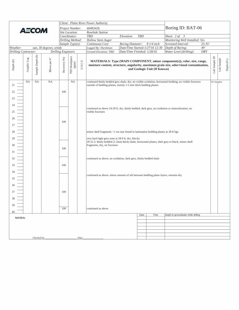
Client: Platte River Power AuthorityProject Number: 60483426 Boring ID: BAT-06Site Location: Rawhide StationCoordinates: TBD Elevation: TBD Sheet: 2 of 3Drilling Method: Hollow Stem Auger Monitoring Well Installed: YesSample Type(s): Continuous Core Boring Diameter: 8 1/4 inch Screened Interval: 25-35'
Weather: sun, 30 degrees, windy Logged By: Hurshman Date/Time Started:1/27/16 12:30 Depth of Boring: 49'Drilling Contractor: Drilling Engineers Ground Elevation: TBD Date/Time Finished: 1/28/16 Water Level (drilling): DRY
Dep
th (f
t)
Gra
phic
Log
Sam
ple
Dep
th (f
t)
Rec
over
y (%
)
PID
Hea
dspa
ce
(ppm
)
U.S
.C.S MATERIALS: Type (MAIN COMPONENT, minor component(s)), color, size, range,
moisture content, structure, angularity, maximum grain size, odor/visual contamination, and Geologic Unit (If Known)
Lab
Sam
ple
ID
Lab
Sam
ple
Dep
th (F
t.)
NA NA NA NA continued thinly bedded grey shale, dry, no visible oxidation, horizontal bedding, no visible fractures No Samples21 outside of bedding planes, mainly 1-2 mm thick bedding planes
22 100
23
24continued as above 24-29 ft, dry, thinly bedded, dark grey, no oxidation or mineralization, no
25 visible fractures
26100
27
28 minor shell fragments ~1 cm size found in lamination bedding planes at 28 ft bgs
29 very hard light grey zone at 28.9 ft, dry, blocky29-31.5: thinly bedded (1-2mm thick) shale, horizontal planes, dark grey to black, minor shell
30 fragments, dry, no fractures100
31
32 continued as above, no oxidation, dark grey, thinly bedded shale
33 100
34continued as above, minor amount of silt between bedding plane layers, remains dry
35
36
37 100
38
39100 continued as above
40Date Time Depth to groundwater while drilling
NOTES:
Checked by __________________________Date:________________
Blo
ws p
er 6
"
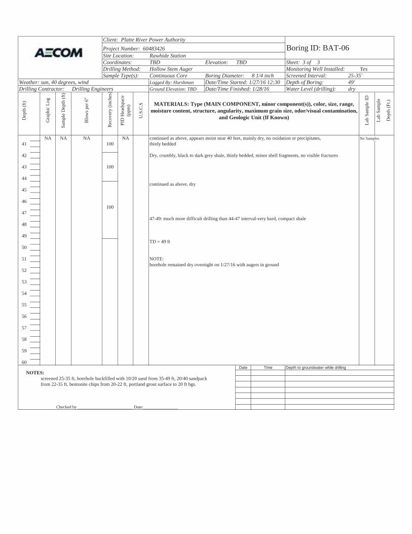
Client: Platte River Power AuthorityProject Number: 60483426 Boring ID: BAT-06Site Location: Rawhide StationCoordinates: TBD Elevation: TBD Sheet: 3 of 3Drilling Method: Hollow Stem Auger Monitoring Well Installed: YesSample Type(s): Continuous Core Boring Diameter: 8 1/4 inch Screened Interval: 25-35'
Weather: sun, 40 degrees, wind Logged By: Hurshman Date/Time Started: 1/27/16 12:30 Depth of Boring: 49'Drilling Contractor: Drilling Engineers Ground Elevation: TBD Date/Time Finished: 1/28/16 Water Level (drilling): dry
Dep
th (f
t)
Gra
phic
Log
Sam
ple
Dep
th (f
t)
Rec
over
y (in
ches
)
PID
Hea
dspa
ce
(ppm
)
U.S
.C.S MATERIALS: Type (MAIN COMPONENT, minor component(s)), color, size, range,
moisture content, structure, angularity, maximum grain size, odor/visual contamination, and Geologic Unit (If Known)
Lab
Sam
ple
ID
Lab
Sam
ple
Dep
th (F
t.)
NA NA NA NA continued as above, appears moist near 40 feet, mainly dry, no oxidation or precipitates, No Samples41 100 thinly bedded
42 Dry, crumbly, black to dark grey shale, thinly bedded, minor shell fragments, no visible fractures
43 100
44continued as above, dry
45
46100
4747-49: much more difficult drilling than 44-47 interval-very hard, compact shale
48
49TD = 49 ft
50
51borehole remained dry overnight on 1/27/16 with augers in ground
52
53
54
55
56
57
58
59
60Date Time Depth to groundwater while drilling
NOTES:screened 25-35 ft, borehole backfilled with 10/20 sand from 35-49 ft, 20/40 sandpackfrom 22-35 ft, bentonite chips from 20-22 ft, portland grout surface to 20 ft bgs.
Checked by __________________________Date:________________
Blo
ws p
er 6
"
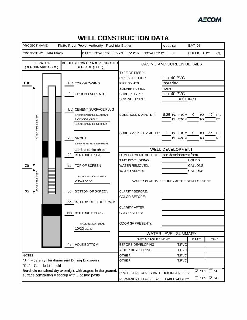
WELL ID:
PROJECT NO: DATE INSTALLED: INSTALLED BY: JH CL
PIPE SCHEDULE:TBD TBD PIPE JOINTS:
SOLVENT USED:0 SCREEN TYPE:
SCR. SLOT SIZE: INCH
TBDBOREHOLE DIAMETER 8.25 IN. FROM 0 TO 49 FT.
IN. FROM TO FT.
SURF. CASING DIAMETER 2 IN. FROM 0 TO 35 FT.20 IN. FROM TO FT.
22 DEVELOPMENT METHOD:TIME DEVELOPING: HOURS
25 25 WATER REMOVED: GALLONSWATER ADDED: GALLONS
35 35 CLARITY BEFORE:COLOR BEFORE:
35CLARITY AFTER:
NA COLOR AFTER:
ODOR (IF PRESENT):
49 BEFORE DEVELOPING
AFTER DEVELOPING:
NOTES: OTHEROTHER
PROTECTIVE COVER AND LOCK INSTALLED?
PERMANENT, LEGIBLE WELL LABEL ADDED?
"JH" = Jeremy Hurshman and Drilling Engineers T/PVC"CL" = Camille LittlefieldBorehole remained dry overnight with augers in the ground, surface completion = stickup with 3 bollard posts
T/PVC
T/PVC
BACKFILL MATERIAL
10/20 sandWATER LEVEL SUMMARY
SWE MEASUREMENT DATE TIMEHOLE BOTTOM T/PVC
BOTTOM OF SCREEN
BOTTOM OF FILTER PACK
BENTONITE PLUG
TOP OF SCREEN
SCR
EEN
LEN
GTH
FILTER PACK MATERIAL
20/40 sand WATER CLARITY BEFORE / AFTER DEVELOPMENT
GROUTBENTONITE SEAL MATERIAL
3/8" bentonite chips WELL DEVELOPMENTBENTONITE SEAL see development form
CEMENT SURFACE PLUGGROUT/BACKFILL MATERIAL
Portland groutGROUT/BACKFILL METHOD
sch. 40 PVCTOP OF CASING threaded
RIS
ER P
IPE
LEN
GTH
noneGROUND SURFACE sch. 40 PVC
0.01
ELEVATION (BENCHMARK: USGS)
DEPTH BELOW OR ABOVE GROUND SURFACE (FEET)
CASING AND SCREEN DETAILS
TYPE OF RISER:
WELL CONSTRUCTION DATAPROJECT NAME: Platte River Power Authority - Rawhide Station BAT-06
60483426 1/27/16-1/28/16 CHECKED BY:
YES NO
YES NO
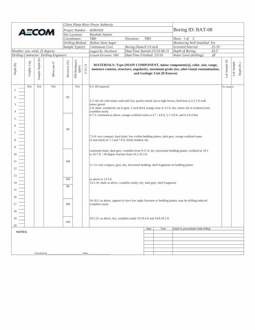
Client:Platte River Power AuthorityProject Number: 60483426 Boring ID: BAT-08Site Location: Rawhide StationCoordinates: TBD Elevation: TBD Sheet: 1 of 3Drilling Method: Hollow Stem Auger Monitoring Well Installed: YesSample Type(s): Continuous Core Boring Diame8 1/4 inch Screened Interval: 25-35'
Weather: sun, wind, 25 degrees Logged By: Hurshman Date/Time Started:2/5/16 08:15 Depth of Boring: 43.5'Drilling Contractor: Drilling Engineers Ground Elevation: TBD Date/Time Finished: 2/5/16 Water Level (drilling): 28'
Dep
th (f
t)
Gra
phic
Log
Sam
ple
Dep
th (f
t)
Rec
over
y (%
)
PID
Hea
dspa
ce
(ppm
)
U.S
.C.S MATERIALS: Type (MAIN COMPONENT, minor component(s)), color, size, range,
moisture content, structure, angularity, maximum grain size, odor/visual contamination, and Geologic Unit (If Known)
Lab
Sam
ple
ID
Lab
Sam
ple
Dep
th (F
t.)
NA NA NA NA 0-2: fill material No samples 1
2 852-3: dry silt with minor sand and clay, poorly sorted, tan to light brown, hard lens at 2-2.2 ft with
3 minor gravel3-4: shale, weathered, tan to grey, 2 inch thick orange zone at 3.5 ft, dry, minor silt in oxidized zone
4 crumbles easily4-7.3: continued as above, orange oxidized zones at 4.7 - 4.8 ft, 5.7-5.8 ft, and 6.2-6.4 feet
5
690
77.3-9: very compact, hard shale, few visible bedding planes, dark grey, orange oxidized zones
8 (2 mm thick) at 7.3 and 7.8 ft, thinly bedded, dry
9continued shale, dark grey, crumbles from 9-11 ft, dry, horizontal bedding planes, oxidized at 10.3
10 to 10.7 ft, ~30 degree fracture from 10.2-10.3 ft
11 10011-13: very compact, grey, dry, horizontal bedding, shell fragments on bedding planes
12
13100 as above to 13.5 ft
14 13.5-16: shale as above, crumbles easily, dry, dark grey, shell fragments80
15
1616-18.5: as above, appears to have low angle fractures or bedding planes, may be drilling induced,
17 100 crumbles easily
18
19 18.5-21: as above, dry, crumbles easily 19-19.4 ft and 19.8-20.1 ft100
20Date Time Depth to groundwater while drilling
NOTES:
Checked by __________________________Date:________________
Blo
ws p
er 6
"
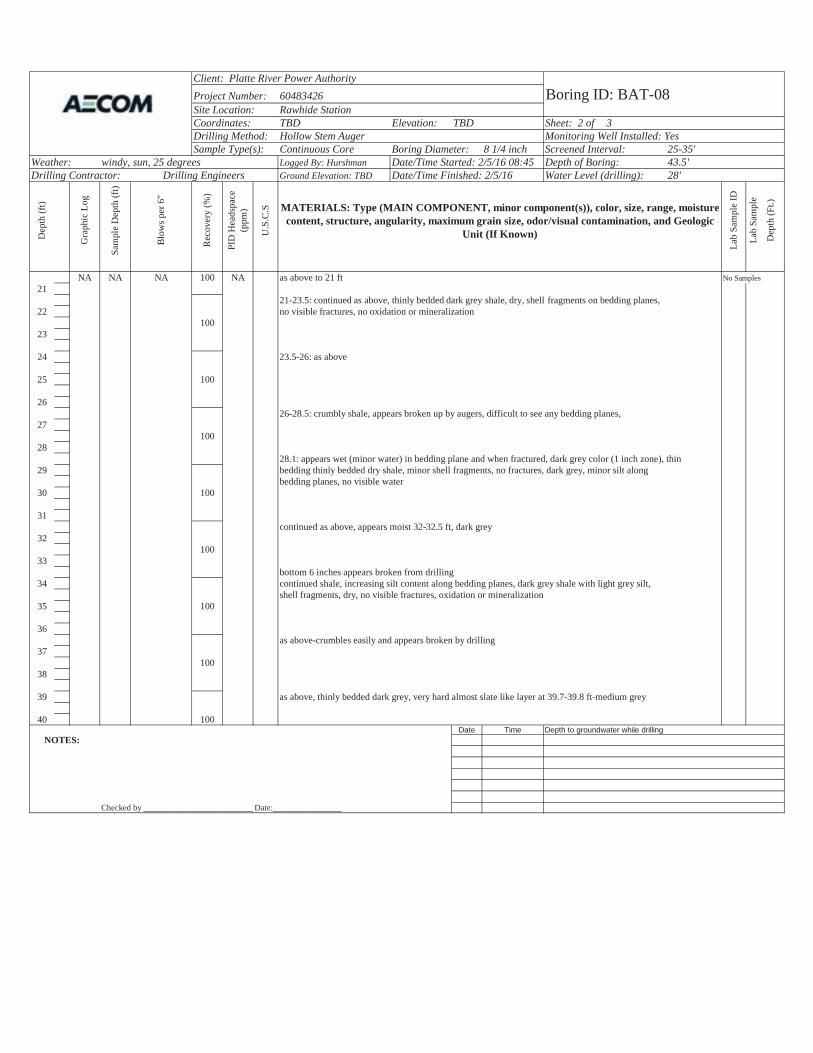
Client: Platte River Power AuthorityProject Number: 60483426 Boring ID: BAT-08Site Location: Rawhide StationCoordinates: TBD Elevation: TBD Sheet: 2 of 3Drilling Method: Hollow Stem Auger Monitoring Well Installed: YesSample Type(s): Continuous Core Boring Diameter: 8 1/4 inch Screened Interval: 25-35'
Weather: windy, sun, 25 degrees Logged By: Hurshman Date/Time Started: 2/5/16 08:45 Depth of Boring: 43.5'Drilling Contractor: Drilling Engineers Ground Elevation: TBD Date/Time Finished: 2/5/16 Water Level (drilling): 28'
Dep
th (f
t)
Gra
phic
Log
Sam
ple
Dep
th (f
t)
Rec
over
y (%
)
PID
Hea
dspa
ce
(ppm
)
U.S
.C.S MATERIALS: Type (MAIN COMPONENT, minor component(s)), color, size, range, moisture
content, structure, angularity, maximum grain size, odor/visual contamination, and Geologic Unit (If Known)
Lab
Sam
ple
ID
Lab
Sam
ple
Dep
th (F
t.)
NA NA NA 100 NA as above to 21 ft No Samples21
2221-23.5: continued as above, thinly bedded dark grey shale, dry, shell fragments n bedding planes,no visible fractures, no oxidation or mineralization
10023
24 23.5-26: as above
25 100
2626-28.5: crumbly shale, appears broken up by augers, difficult to see any bedding planes,
27100
2828.1: appears wet (minor water) in bedding plane and when fractured, dark grey color (1 inch zone), thin
29 bedding thinly bedded dry shale, minor shell fragments, no fractures, dark grey, minor silt along bedding planes, no visible water
30 100
31continued as above, appears moist 32-32.5 ft, dark grey
32100
33bottom 6 inches appears broken from drilling
34 continued shale, increasing silt content along bedding planes, dark grey shale with light grey silt, shell fragments, dry, no visible fractures, oxidation or mineralization
35 100
36as above-crumbles easily and appears broken by drilling
37100
38
39 as above, thinly bedded dark grey, very hard almost slate like layer at 39.7-39.8 ft-medium grey
40 100Date Time Depth to groundwater while drilling
NOTES:
Checked by __________________________Date:________________
Blo
ws p
er 6
"
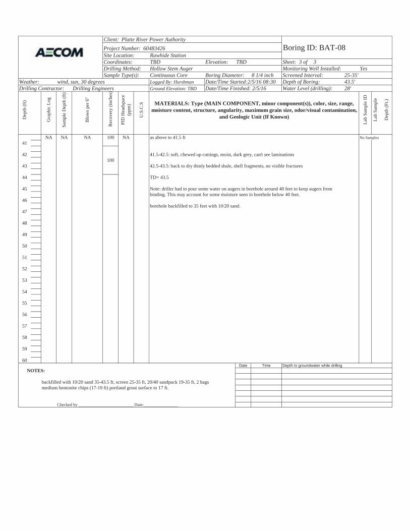
Client: Platte River Power AuthorityProject Number: 60483426 Boring ID: BAT-08Site Location: Rawhide StationCoordinates: TBD Elevation: TBD Sheet: 3 of 3Drilling Method: Hollow Stem Auger Monitoring Well Installed: YesSample Type(s): Continuous Core Boring Diameter: 8 1/4 inch Screened Interval: 25-35'
Weather: wind, sun, 30 degrees Logged By: Hurshman Date/Time Started:2/5/16 08:30 Depth of Boring: 43.5'Drilling Contractor: Drilling Engineers Ground Elevation: TBD Date/Time Finished: 2/5/16 Water Level (drilling): 28'
Dep
th (f
t)
Gra
phic
Log
Sam
ple
Dep
th (f
t)
Rec
over
y (in
ches
)
PID
Hea
dspa
ce
(ppm
)
U.S
.C.S MATERIALS: Type (MAIN COMPONENT, minor component(s)), color, size, range,
moisture content, structure, angularity, maximum grain size, odor/visual contamination, and Geologic Unit (If Known)
Lab
Sam
ple
ID
Lab
Sam
ple
Dep
th (F
t.)
NA NA NA 100 NA as above to 41.5 ft No Samples41
42 41.5-42.5: soft, chewed up cuttings, moist, dark grey, can't see laminations100
43 42.5-43.5: back to dry thinly bedded shale, shell fragments, no visible fractures
44 TD= 43.5
45 Note: driller had to pour some water on augers in borehole around 40 feet to keep augers from binding. This may account for some moisture seen in borehole below 40 feet.
46borehole backfilled to 35 feet with 10/20 sand.
47
48
49
50
51
52
53
54
55
56
57
58
59
60Date Time Depth to groundwater while drilling
NOTES:
backfilled with 10/20 sand 35-43.5 ft, screen 25-35 ft, 20/40 sandpack 19-35 ft, 2 bags medium bentonite chips (17-19 ft) portland grout surface to 17 ft.
Checked by __________________________Date:________________
Blo
ws p
er 6
"

WELL ID:
PROJECT NO: DATE INSTALLED: INSTALLED BY: JH CL
PIPE SCHEDULE:TBD TBD PIPE JOINTS:
SOLVENT USED:SCREEN TYPE:SCR. SLOT SIZE: INCH
TBDBOREHOLE DIAMETER 8.25 IN. FROM 0 TO 43.5 FT.
IN. FROM TO FT.
SURF. CASING DIAMETER 2 IN. FROM 0 TO 35 FT.17 IN. FROM TO FT.
19 DEVELOPMENT METHOD:TIME DEVELOPING: HOURS
25 25 WATER REMOVED: GALLONSWATER ADDED: GALLONS
35 35 CLARITY BEFORE:COLOR BEFORE:
35CLARITY AFTER:
NA COLOR AFTER:
ODOR (IF PRESENT):
43.5 BEFORE DEVELOPING
AFTER DEVELOPING:
NOTES: OTHEROTHER
PROTECTIVE COVER AND LOCK INSTALLED?
PERMANENT, LEGIBLE WELL LABEL ADDED?
"JH" = Jeremy Hurshman and Drilling Engineers T/PVC"CL" = Camille LittlefieldSurface completion = flushmount with 2'x2' concrete pad
T/PVC
T/PVC
BACKFILL MATERIAL
10/20 sandWATER LEVEL SUMMARY
SWE MEASUREMENT DATE TIMEHOLE BOTTOM T/PVC
BOTTOM OF SCREEN
BOTTOM OF FILTER PACK
BENTONITE PLUG
TOP OF SCREEN
SCR
EEN
LEN
GTH
FILTER PACK MATERIAL
20/40 sand WATER CLARITY BEFORE / AFTER DEVELOPMENT
BENTONITE SEAL MATERIAL
WELL DEVELOPMENT3/8" medium chips BENTONITE SEAL see development form
CEMENT SURFACE PLUGGROUT/BACKFILL MATERIAL
Portland groutGROUT/BACKFILL METHOD
GROUT
sch. 40 PVCTOP OF CASING threaded
RIS
ER P
IPE
LEN
GTH
nonesch. 40 PVC
0.01
ELEVATION (BENCHMARK: USGS)
DEPTH BELOW OR ABOVE GROUND SURFACE (FEET)
CASING AND SCREEN DETAILS
0 GROUND SURFACE TYPE OF RISER:
WELL CONSTRUCTION DATAPROJECT NAME: Platte River Power Authority - Rawhide Station BAT-08
60483426 2/5/2016 CHECKED BY:
YES NO
YES NO
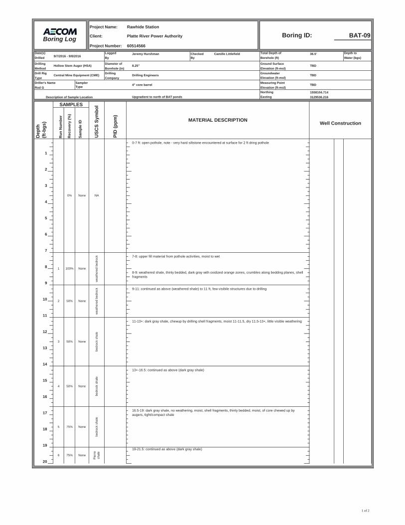
Project Name:
Client: BAT-09Project Number:
Date(s) Logged Jeremy Hurshman Checked Camille Littlefield Total Depth of 36.5' Depth toDrilled By By Borehole (ft) Water (bgs)
Drilling Diameter of Ground SurfaceMethod Borehole (in) Elevation (ft-msl)Drill Rig Drilling GroundwaterType Company Elevation (ft-msl)Driller's Name Measuring Point
Elevation (ft-msl)Northing 1558104.714
Upgradient to north of BAT ponds Easting 3129536.216
Dep
th
(ft
-bgs
)
Run
Num
ber
Rec
over
y (%
)
Sam
ple
ID Well Construction
1
2
3
4
5
6
7
8
9
10
11
12
13
14
15
16
17
18
1919-21.5: continued as above (dark gray shale)
20
7-8: upper fill material from pothole activities, moist to wet
8-9: weathered shale, thinly bedded, dark gray with oxidized orange zones, crumbles along bedding planes, shell fragments
0% None
100% None
50%
9-11: continued as above (weathered shale) to 11 ft, few visibile structures due to drilling
3 None
bedr
ock
shal
e
11-13+: dark gray shale, chewup by drilling shell fragments, moist 11-11.5, dry 11.5-13+, little visible weathering
NA
0-7 ft: open pothole, note - very hard siltstone encountered at surface for 2 ft dring pothole
1
wea
ther
ed b
edro
ck
5 75% None
bedr
ock
shal
e
2
wea
ther
ed b
edro
ck
None50%
13+-16.5: continued as above (dark gray shale)
16.5-19: dark gray shale, no weathering, moist, shell fragments, thinly bedded, moist, of core chewed up by augers, tight/compact shale
Pie
rre
shal
e
None75%6
4 50% None
bedr
ock
shal
e
SAMPLESU
SCS
Sym
bol
PID
(ppm
)MATERIAL DESCRIPTION
SamplerType 4" core barrel TBD
Rod G
Description of Sample Location
Hollow Stem Auger (HSA) 8.25" TBD
Central Mine Equipment (CME) Drilling Engineers TBD
Boring Log
Rawhide Station
Platte River Power Authority Boring ID:60514566
9/7/2016 - 9/8/2016
1 of 2
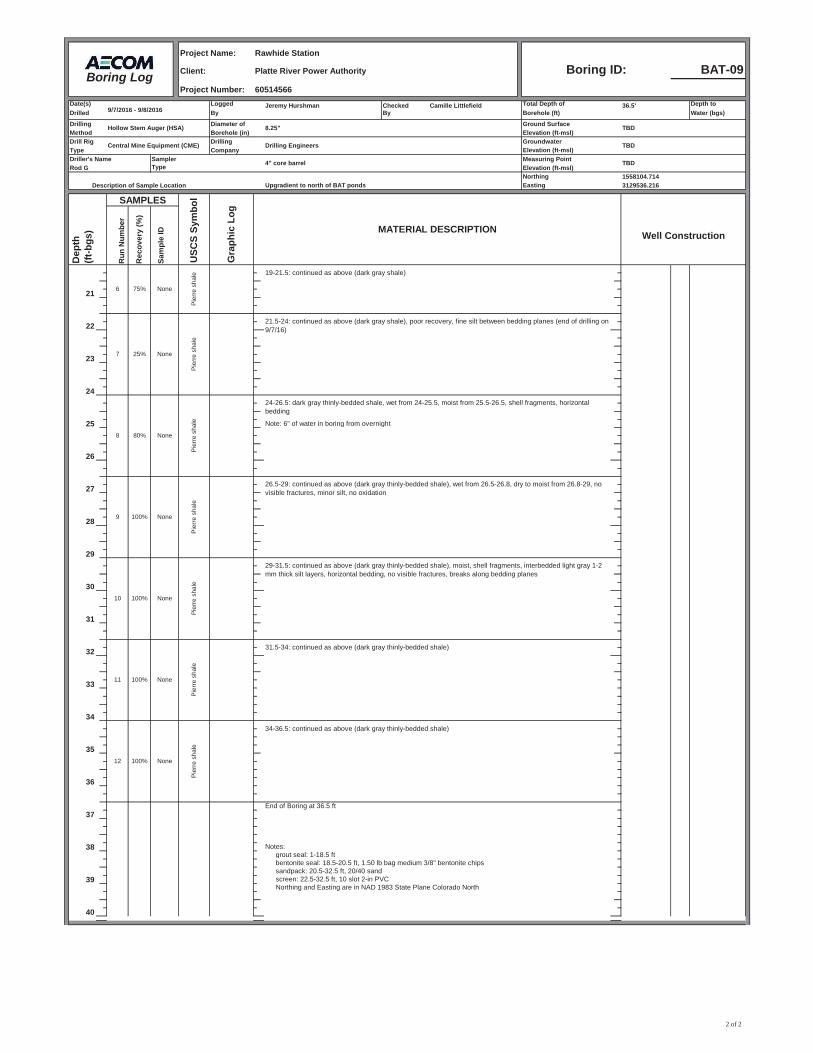
Project Name:
Client: BAT-09Project Number:
Date(s) Logged Jeremy Hurshman Checked Camille Littlefield Total Depth of 36.5' Depth toDrilled By By Borehole (ft) Water (bgs)
Drilling Diameter of Ground SurfaceMethod Borehole (in) Elevation (ft-msl)Drill Rig Drilling GroundwaterType Company Elevation (ft-msl)Driller's Name Measuring Point
Elevation (ft-msl)Northing 1558104.714
Upgradient to north of BAT ponds Easting 3129536.216
Dep
th
(ft
-bgs
)
Run
Num
ber
Rec
over
y (%
)
Sam
ple
ID Well Construction
21
22
23
24
25 Note: 6" of water in boring from overnight
26
27
28
29
30
31
32
33
34
35
36
End of Boring at 36.5 ft37
38 Notes: grout seal: 1-18.5 ft bentonite seal: 18.5-20.5 ft, 1.50 lb bag medium 3/8" bentonite chipssandpack: 20.5-32.5 ft, 20/40 sand
39 screen: 22.5-32.5 ft, 10 slot 2-in PVCNorthing and Easting are in NAD 1983 State Plane Colorado North
40
SAMPLESU
SCS
Sym
bol
Gra
phic
Log
MATERIAL DESCRIPTION
SamplerType 4" core barrel TBD
Rod G
Description of Sample Location
Hollow Stem Auger (HSA) 8.25" TBD
Central Mine Equipment (CME) Drilling Engineers TBD
AECOM Boring Log
Rawhide Station
Platte River Power Authority Boring ID:60514566
9/7/2016 - 9/8/2016
Pie
rre
shal
e
None75%6
19-21.5: continued as above (dark gray shale)
21.5-24: continued as above (dark gray shale), poor recovery, fine silt between bedding planes (end of drilling on 9/7/16)
Pie
rre
shal
e
None25%7
24-26.5: dark gray thinly-bedded shale, wet from 24-25.5, moist from 25.5-26.5, shell fragments, horizontal bedding
Pie
rre
shal
e
None80%8
9 100% None
Pie
rre
shal
e
26.5-29: continued as above (dark gray thinly-bedded shale), wet from 26.5-26.8, dry to moist from 26.8-29, no visible fractures, minor silt, no oxidation
Pie
rre
shal
e
None100%10
29-31.5: continued as above (dark gray thinly-bedded shale), moist, shell fragments, interbedded light gray 1-2 mm thick silt layers, horizontal bedding, no visible fractures, breaks along bedding planes
31.5-34: continued as above (dark gray thinly-bedded shale)
34-36.5: continued as above (dark gray thinly-bedded shale)
Pie
rre
shal
e
None100%11
12 100% None
Pie
rre
shal
e
2 of 2
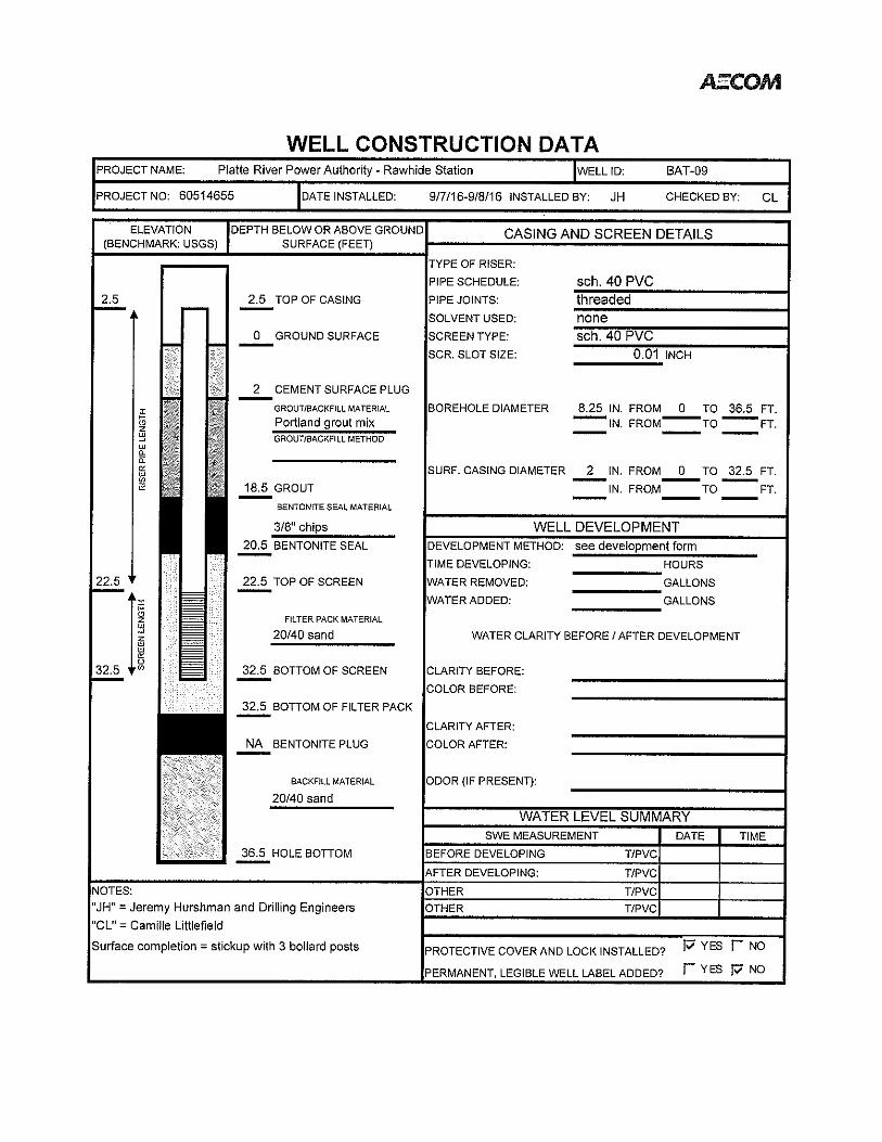

AECOM BAT Impoundments Groundwater Detection Monitoring Plan Platte River Power Authority
October 2017
Appendix B. Standard OperatingProcedures (SOPs)
Standard Operating Procedure
Chain-of-Custody Procedures
Procedure Number: 001
Revision No.: 0
Revision Date: October 2017
Date:
October 10, 2017
SOP Author, Camille Littlefield
Date:
October 10, 2017
SOP Reviewer, Geoff Webb
AECOM Environment
Standard Operating Procedure
Chain-of-Custody Procedures
SOP No.: 001
Revision: 0
Date: October 2017
Page i of i
Contents
1.0 Scope and Applicability .................................................................................................................... 1
2.0 Health and Safety Considerations .................................................................................................. 1
3.0 Interferences ...................................................................................................................................... 1
4.0 Equipment and Materials.................................................................................................................. 1
5.0 Procedures ......................................................................................................................................... 2
6.0 Quality Assurance / Quality Control ............................................................................................... 4
7.0 Data and Records Management ...................................................................................................... 5
8.0 Personnel Qualifications and Training ........................................................................................... 5
9.0 References ......................................................................................................................................... 5
10.0 Revision History ................................................................................................................................ 6

AECOM Environment
Standard Operating Procedure
Chain-of-Custody Procedures
SOP No.: 001
Revision: 0
Date: October 2017
Page 1 of 8
1.0 Scope and Applicability
1.1 Chain of custody (COC) is defined as the unbroken trail of accountability for the physical security of
samples, data, and records (USEPA Glossary of Quality-Related Terms). This Standard Operating
Procedure (SOP) describes COC procedures applicable to environmental samples collected by
AECOM during field sampling and analysis programs. Custody procedures within the laboratories
analyzing the samples are not addressed.
1.2 Samples are physical evidence. The objective of COC procedures is to provide sufficient evidence of
sample integrity to satisfy data defensibility requirements in legal or regulatory situations.
1.3 The National Enforcement Investigations Center (NEIC) of the United States Environmental Protection
Agency (USEPA) defines custody of evidence in the following manner:
It is in your actual possession;
It is in your view, after being in your physical possession;
It was in your possession and then you locked or sealed it up to prevent tampering; or
It is in a secure area.
2.0 Health and Safety Considerations
2.1 The health and safety considerations for the work associated with this SOP, including both potential
physical and chemical hazards, will be addressed in a site-specific Health and Safety Plan (HASP). In
the absence of a site-specific HASP, work will be conducted according to the AECOM Health and
Safety Policy and Procedures Manual and/or direction from the Regional Health and Safety Manager.
3.0 Interferences
3.1 The following may impact the legal or regulatory defensibility of the data:
The samples are not accompanied by a COC form; or
The information recorded on the COC form is incomplete, inaccurate, or differs from the
information recorded on the sample containers.
4.0 Equipment and Materials
4.1 The following materials are relevant to this procedure:
COC Form (Figure 1);
Sample labels;
COC tape or seal (Figure 2);
Indelible pen or Sharpie™; and
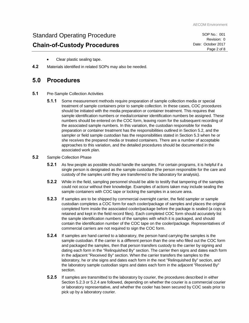
AECOM Environment
Standard Operating Procedure
Chain-of-Custody Procedures
SOP No.: 001
Revision: 0
Date: October 2017
Page 2 of 8
Clear plastic sealing tape.
4.2 Materials identified in related SOPs may also be needed.
5.0 Procedures
5.1 Pre-Sample Collection Activities
5.1.1 Some measurement methods require preparation of sample collection media or special
treatment of sample containers prior to sample collection. In these cases, COC procedures
should be initiated with the media preparation or container treatment. This requires that
sample identification numbers or media/container identification numbers be assigned. These
numbers should be entered on the COC form, leaving room for the subsequent recording of
the associated sample numbers. In this variation, the custodian responsible for media
preparation or container treatment has the responsibilities outlined in Section 5.2, and the
sampler or field sample custodian has the responsibilities stated in Section 5.3 when he or
she receives the prepared media or treated containers. There are a number of acceptable
approaches to this variation, and the detailed procedures should be documented in the
associated work plan.
5.2 Sample Collection Phase
5.2.1 As few people as possible should handle the samples. For certain programs, it is helpful if a
single person is designated as the sample custodian (the person responsible for the care and
custody of the samples until they are transferred to the laboratory for analysis).
5.2.2 While in the field, sampling personnel should be able to testify that tampering of the samples
could not occur without their knowledge. Examples of actions taken may include sealing the
sample containers with COC tape or locking the samples in a secure area.
5.2.3 If samples are to be shipped by commercial overnight carrier, the field sampler or sample
custodian completes a COC form for each cooler/package of samples and places the original
completed form inside the associated cooler/package before the package is sealed (a copy is
retained and kept in the field record files). Each completed COC form should accurately list
the sample identification numbers of the samples with which it is packaged, and should
contain the identification number of the COC tape on the cooler/package. Representatives of
commercial carriers are not required to sign the COC form.
5.2.4 If samples are hand carried to a laboratory, the person hand carrying the samples is the
sample custodian. If the carrier is a different person than the one who filled out the COC form
and packaged the samples, then that person transfers custody to the carrier by signing and
dating each form in the "Relinquished By" section. The carrier then signs and dates each form
in the adjacent "Received By" section. When the carrier transfers the samples to the
laboratory, he or she signs and dates each form in the next "Relinquished By" section, and
the laboratory sample custodian signs and dates each form in the adjacent "Received By"
section.
5.2.5 If samples are transmitted to the laboratory by courier, the procedures described in either
Section 5.2.3 or 5.2.4 are followed, depending on whether the courier is a commercial courier
or laboratory representative, and whether the cooler has been secured by COC seals prior to
pick up by a laboratory courier.
AECOM Environment
Standard Operating Procedure
Chain-of-Custody Procedures
SOP No.: 001
Revision: 0
Date: October 2017
Page 3 of 8
5.3 Sample Labeling
5.3.1 Labeling of samples occurs at the time of sample collection.
5.3.2 Waterproof, adhesive labels are preferred. Labels should be applied to the container, not the
lid whenever possible. Additional interior labels may be required for certain biological
samples.
5.3.3 Sample tags may be required for certain samples. If tags are utilized, their use will be
addressed in a site-specific work plan.
5.3.4 Labels should be completed in waterproof, indelible ink. Covering the label with clear plastic
tape is recommended to protect the legibility of the label and to prevent the label from
detaching from the sample container.
5.3.5 The following information should be recorded on the sample label:
Project identification (project name and number/client/site);
Field sample identification code (exactly as it appears on the COC form);
Sampler’s initials;
Date and time of sample collection;
Analyses requested; and
Preservation.
5.4 Documentation of Sample History
5.4.1 Sample history includes, but is not limited to, preparation of sample containers or collection
media (e.g., wipes), collection, handling (i.e., subsampling or compositing), storage, shipment,
analytical preparation and analysis, reporting, and disposal.
5.5 Documentation of Custody
5.5.1 It is recommended that a COC form be initiated upon sample collection. If this is not feasible
for a particular event, the COC form may be initiated at the time of sample packaging. If this is
the case, the sample collection records will serve as the initial custody document and will
document the collection of the sample (outlined in Section 5.3.5).
5.6 The following information is recorded on the COC form:
Project identification (AECOM project number, client, site name and location);
Page number (for example, 1 of 2, 2 of 2);
Field sample identification code (must be unique to the sampling event and program, and must
agree exactly with the field sample identification code recorded on the bottle label);
Sampling point location (optional if recorded elsewhere in field records);
Date and time of sample collection;
Sample matrix (e.g., soil, water, air, etc…);
Preservative;
Analysis requested;
AECOM Environment
Standard Operating Procedure
Chain-of-Custody Procedures
SOP No.: 001
Revision: 0
Date: October 2017
Page 4 of 8
Number of containers;
Type of sample (i.e., grab or composite) (identifying if aqueous samples have been filtered in the
field is recommended);
Signature(s) of sampling personnel and signatures of all personnel handling, receiving, and
relinquishing the samples;
Date(s) and time(s) of each sample transfer;
Sampler remarks (these comments may serve to alert the laboratory to highly impacted samples
or identify quality control (QC) sample requirements);
Airbill number (if shipped by overnight commercial carrier); and
Laboratory name and address.
5.7 COC Tape Numbers
5.7.1 The COC is filled out completely and legibly in indelible ink. There should be no unexplained
blank spaces. Blank lines should be lined out and initialed and dated.
5.7.2 Corrections are made, if necessary, by drawing a single line through and initialing and dating
the error. The correct information is recorded with indelible ink.
5.7.3 Information on the COC should agree exactly with that recorded on the sample containers.
Discrepancies may result in the samples being incorrectly logged into the laboratory or delays
in initiating sample analysis.
5.8 Sample Receipt and Inspection
5.8.1 Upon sample receipt, the coolers or packages are inspected for general condition and COC
tape condition. The coolers or boxes are then opened and each sample is inspected for
damage.
5.8.2 Sample containers are removed from packing material and sample label information is verified
against the COC form.
5.8.3 The condition upon receipt, including any discrepancies or problems, is documented and the
COC form is completed by signing and recording the date and time of receipt.
5.8.4 Receipt and inspection of samples by subcontractor analytical laboratories will adhere to
written procedures established by the laboratory.
6.0 Quality Assurance / Quality Control
6.1 The records generated in this procedure are subject to review by the sampling team leader, project
manager, or designee.
6.2 The field team leader is responsible for reviewing the chain-of-custody forms for completeness and
accuracy prior to sample shipment.

AECOM Environment
Standard Operating Procedure
Chain-of-Custody Procedures
SOP No.: 001
Revision: 0
Date: October 2017
Page 5 of 8
7.0 Data and Records Management
7.1 The records generated in this procedure are part of the permanent record supporting the associated
measurements and may include, as applicable, the COC forms, sample tags, carrier waybills, and field
and laboratory records of sample history (i.e., collection, handling, storage, analysis, etc…).
7.2 Unanticipated changes to the procedures or materials described in this SOP (deviations) should be
appropriately, thoroughly documented in the project records.
7.3 Records associated with the activities described in this SOP should be maintained according to the
project-specific document management policy.
8.0 Personnel Qualifications and Training
8.1 Qualifications and Training
8.1.1 The individual executing these procedures should have read, and be familiar with, the
requirements in this SOP.
8.1.2 No specialized skills are necessary in order to implement these procedures; however, an
understanding of the concept of custody is useful.
8.2 Responsibilities
8.2.1 The Project Manager is responsible for providing the project team with the materials,
resources and guidance necessary to properly execute the procedures described in this SOP.
8.2.2 The individual performing the work is responsible for implementing the procedures as
described in this SOP, and in project-specific work plans.
8.2.3 For certain sampling programs, the Project Manager, sampling team leader or designee may
assign an individual to serve as sample custodian. This individual is responsible for
supervising the implementation of COC procedures in accordance with this SOP and project-
specific work plans.
9.0 References
American Society for Testing and Materials (ASTM). 2004. Standard Guide for Sample Chain-of-
Custody Procedures. D 4840-99 (Reapproved 2004).ENSR SOP 1009 − Data Validation.
United States Environmental Protection Agency. 2001. Guidance for Preparing Standard Operating
Procedures (SOPs). USEPA QA/G-6. EPA/240/B-01/004. USEPA Office of Environmental
Information, Washington, DC. March 2001.
AECOM Environment
Standard Operating Procedure
Chain-of-Custody Procedures
SOP No.: 001
Revision: 0
Date: October 2017
Page 6 of 8
10.0 Revision History
Revision Date Changes
0 October 2017 Initial Version
AECOM Environment
Standard Operating Procedure
Chain-of-Custody Procedures
SOP No.: 001
Revision: 0
Date: October 2017
Page 7 of 8
Figure 1: Example of Chain-of-Custody
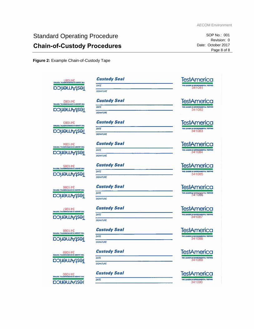
AECOM Environment
Standard Operating Procedure
Chain-of-Custody Procedures
SOP No.: 001
Revision: 0
Date: October 2017
Page 8 of 8
Figure 2: Example Chain-of-Custody Tape
Standard Operating Procedure
Package and Shipment of Environmental Samples
Procedure Number: 002
Revision No.: 0
Revision Date: October 2017
Date:
October 10, 2017
SOP Author, Camille Littlefield
Date:
October 10, 2017
SOP Reviewer, Geoff Webb
AECOM Environment
Standard Operating Procedure
Package and Shipment of Environmental Samples
SOP No.: 002
Revision: 0
Date: October 2017
Page i of i
Contents
1.0 Scope and Applicability .................................................................................................................... 1
2.0 Health and Safety Considerations .................................................................................................. 1
3.0 Interferences ...................................................................................................................................... 2
4.0 Equipment and Materials.................................................................................................................. 2
5.0 Procedures ......................................................................................................................................... 2
6.0 Quality Assurance / Quality Control ............................................................................................... 6
7.0 Data and Records Management ...................................................................................................... 6
8.0 Personnel Qualifications and Training ........................................................................................... 6
9.0 References ......................................................................................................................................... 7
10.0 Revision History ................................................................................................................................ 7

AECOM Environment
Standard Operating Procedure
Package and Shipment of Environmental Samples
SOP No.: 002
Revision: 0
Date: October 2017
Page 1 of 7
1.0 Scope and Applicability
1.1 Purpose and Applicability
1.1.1 This Standard Operating Procedure (SOP) describes the procedures associated with the
package and shipment of environmental samples. Two general categories of samples exist: 1)
environmental samples consisting of water and soil submitted for routine environmental
testing, and 2) waste material samples which include non-hazardous solid wastes and/or
hazardous wastes, as defined by 40 CFR Part 261, submitted for environmental testing or
bench/pilot-scale treatability testing. Packaging and shipping procedures will differ for the two
sample categories.
1.1.2 This SOP is applicable to the package and shipment of environmental samples submitted for
routine environmental testing. Environmental samples are not considered a hazardous waste
by definition; therefore, the Department of Transportation (DOT) regulations regarding sample
transportation do not apply. Environmental samples do, however, require stringent packaging
and shipping measures to confirm sample integrity and safety of the individuals handling and
transporting the samples.
1.1.3 This SOP is designed to provide a high degree of certainty that environmental samples will
arrive at their destination intact. This SOP assumes that samples will often require shipping
overnight by a commercial carrier service; therefore, the procedures are more stringent than
may be necessary if a laboratory courier is used, or if samples are transported directly to their
destination by a sampling team member. Should the samples be transported directly to the
laboratory by a laboratory courier or a sampling team member, the procedures may be
modified to reflect a lesser degree of packaging requirements.
1.1.4 Respective state or federal agency (regional office) protocols may require or recommend
specific types of equipment to use in sample packaging, or a specific method of shipment that
may vary from the indicated procedures in this SOP. Deviations from this SOP to
accommodate other regulatory requirements should be reviewed in advance of the field
program, should be explained in the project work plan, and must be documented in the field
project notebook when they occur.
1.2 General Principles
1.2.1 Sample package and shipment generally involves the placement of individual sample
containers into a cooler, or other similar shipping container, and placement of packing
materials and coolant in order to isolate the samples, maintain the required temperature, and
limit the potential for damage to sample containers during transportation.
2.0 Health and Safety Considerations
2.1.1 Sampling personnel should be aware that packaging and shipment of samples involves
potential physical hazards primarily associated with the ocassional handling of broken sample
containers and the lifting of heavy objects. Adequate health and safety measures must be
taken in order to protect sampling personnel from these potential hazards. A project Health
and Safety Plan (HASP) generally addresses physical, and other potential, hazards. A project
HASP must be approved by the project Health and Safety Officer before work commences,
AECOM Environment
Standard Operating Procedure
Package and Shipment of Environmental Samples
SOP No.: 002
Revision: 0
Date: October 2017
Page 2 of 7
must be distributed to all personnel performing sampling, and must be adhered to as field
activities are performed. In the absence of a project HASP, work will be conducted according
to the AECOM Health and Safety Policy and Procedures Manual and/or direction from the
Regional Health and Safety Manager.
3.0 Interferences
Not applicable.
4.0 Equipment and Materials
Sample coolers
Sample containers
Sample labels
Shipping labels
Chain of custody (COC) records
COC tape
Bubble wrap
Wet ice
Packing tape
2-gallon Ziploc® brand freezer bags for ice
Health and Safety supplies
Equipment decontamination materials
Field project notebook and water-proof ink pen
5.0 Procedures
5.1 General Information
5.1.1 Regulatory Information
The extent and nature of sample containerization will be governed by the type of sample,
and a reasonable projection of the sample's hazardous nature and constituents. The
EPA regulations (40 CFR Section 261.4(d)) specify that samples of solid waste, water,
soil or air, collected for the sole purpose of testing, are exempt from regulation under the
Resource Conservation and Recovery Act (RCRA) when any of the following conditions
are applicable:
Samples are being transported to a laboratory for analysis;
AECOM Environment
Standard Operating Procedure
Package and Shipment of Environmental Samples
SOP No.: 002
Revision: 0
Date: October 2017
Page 3 of 7
Samples are being transported to the collector from the laboratory after analysis; and
Samples are being stored (1) by the collector prior to shipment for analyses, (2) by the
analytical laboratory prior to analyses, (3) by the analytical laboratory after testing but
prior to return of sample to the collector or pending the conclusion of a court case.
5.1.2 Sample Information
Sample information to be provided on the COC will follow the Chain of Custody SOP
001.
5.1.3 Laboratory Notifications
Prior to sample collection the Project Manager, or designated alternative, must notify the
laboratory manager of the number of samples, type of samples, approximate collection
dates, and approximate shipment dates for the samples. If the number, type or date of
sample shipment significantly changes due to program changes, which may occur in the
field, the Project Manager or alternate must notify the laboratory of the changes.
Additional notification from the field is often necessary when shipments are scheduled
for Saturday deliveries.
5.2 General Site Preparation
5.2.1 Small Projects
Small projects consisting of a one or two day duration may require package and
shipment of samples using the field vehicle as the sample preparation area. If sample
coolers are to be sent via a third party commercial carrier service, adequate sample
packaging materials should be sent to the project location in prior to sampling, or
purchased from stores located near the site.
5.2.2 Large Projects
Multi-day or week long sampling programs usually require the rental of an office trailer or
the use of existing office/storage facilities for storage of equipment and sample
preparation. If possible, a designated area should be selected for storage of unused
sample containers/coolers, and another area for sample handling, packaging, and
shipping. Handling of environmental samples are preferably to be conducted in a clean
area away from unused sample containers in order to minimize the potential for cross
contamination. Large quantities of packaging materials may require advance special
ordering. Shipping forms/labels may be preprinted to facilitate shipping.
5.2.3 Cooler Inspection and Decontamination
Laboratories will often re-use coolers. Every cooler received at a project location should
be inspected for general condition and cleanliness. Any coolers that have cracked
interior or exterior linings/panels or hinges should be discarded because their insulating
properties are now compromised. Any coolers missing one or both handles should also
be discarded, if replacement handles (e.g., knotted rope handles) cannot be fashioned
in the field. Replacement coolers may be purchased in the field if necessary.
The interior and exterior of each cooler should be inspected for general condition and
cleanliness upon arrival, before use. Excess packing tape and old shipping labels should
be removed. If the cooler interior exhibits visible impacts or odors it should be
AECOM Environment
Standard Operating Procedure
Package and Shipment of Environmental Samples
SOP No.: 002
Revision: 0
Date: October 2017
Page 4 of 7
decontaminated in accordance with the Decontamination of Field Equipment SOP 003.
Drain plugs should be sealed on the inside with duct tape.
5.2.4 Other Considerations
Volatile Organic Compound (VOC) Samples - Sample containers used for VOC analysis
may be grouped into a single cooler, with a separate COC, to limit the number of trip
blanks required for transportation and analysis. Individual VOC samples may also be
placed into Zipper-lock bags in order to further protect the samples.
Impacted Samples - Sample containers with presumed high analyte concentrations
should be isolated within their own cooler with each sample container placed in a sealed
Zipper-lock bag, in order to prevent cross contamination and for health and safety
reasons.
5.3 Sample Packaging Method
5.3.1 Place plastic bubble wrap matting over the base of each cooler or shipping container as
needed to create a cushion of the samples.
5.3.2 Check that each sample container is properly sealed, correctly and legibly labeled, and is
externally clean. Re-label and/or wipe bottles clean if necessary. Wrap each large glass
sample container (250 milliliter (ml) or greater) individually with bubble wrap secured with
tape. Small glass sample containers (i.e., 40 ml vials) can be wrapped in bubble wrap in
groups of two or three containers if they are collected from the same sampling location.
Plastic sample containers do not need to be wrapped in bubble wrap. Place bottles into the
cooler in an upright single layer. Do not stack bottles or place them in the cooler lying on their
sides. If plastic and glass sample containers are used, alternate the placement of each type of
container within the cooler so glass bottles are not placed side by side.
5.3.3 Place additional bubble wrap in any voids between sample containers.
5.3.4 Insert cooler temperature blanks as required.
5.3.5 Double-bag wet ice in 2-gallon Ziploc® brand freezer bags and distribute them in a layer over
the top of the samples.
5.3.6 Add additional bubble wrap or other packing materials to fill the balance of the cooler or
container.
5.3.7 Obtain a piece of COC tape and enter the COC tape number in the appropriate place on the
COC form. Sign and date the COC tape.
5.3.8 Complete the COC form. Do not forget to sign it. If shipping the samples involves the use of a
third party commercial carrier service, sign the COC record thereby relinquishing custody of
the samples. Shippers should not be asked to sign COC records. If a laboratory courier is
used, or if samples are transported directly to the laboratory, the receiving party should accept
custody and sign the COC records. Remove the last copy from the form and retain it with
other field notes. Place the original COC form (with remaining copies) in a Zipper-lock type
plastic bag, and tape the bag to the inside lid of the cooler or shipping container. Refer to the
Chain of Custody SOP 001 for more specific information.
5.3.9 Close the top or lid of the cooler or shipping container.
5.3.10 Place the COC tape over the seal between the cooler and the lid and overlap with transparent
packaging tape, taping the cooler shut and protecting the COC tape.
AECOM Environment
Standard Operating Procedure
Package and Shipment of Environmental Samples
SOP No.: 002
Revision: 0
Date: October 2017
Page 5 of 7
5.3.11 Packaging tape should be placed entirely around the sample shipment containers in order to
seal the lid down. A minimum of three full wraps of packaging tape will be placed in at least
two locations on the cooler. A minimum of one full wrap will be placed around the base of the
cooler over the drain plug to prevent leakage.
5.3.12 Repeat the above steps for each cooler or shipping container.
5.4 Sample Shipping Method
5.4.1 Hand Delivery
When a project member is transporting samples by automobile to the laboratory, the
COC will be maintained by the person transporting the sample and COC tape need not
be used. COC records should be relinquished upon delivery, and a copy of the record
retained in the project file.
5.4.2 Laboratory Courier
Laboratory couriers are usually employees of the analytical laboratory who recieve the
samples. They will accept custody of the samples, and must sign the COC records
before acquiring custody. COC records do not need to be sealed in the cooler although it
is recommended that the coolers be sealed with tape. All other packaging requirements
generally apply unless otherwise specified in the project specific Quality Assurance
Project Plan (QAPP).
If the laboratory courier is not authorized to accept custody of the samples, or if the
requirements of the project plan prevent transfer to the laboratory courier, samples will
be handled as described below in Section 5.4.3.
5.4.3 Third Party Courier
If overnight shipment is required, a third party package delivery service should be used.
Transport the cooler to the package delivery service office or arrange for package pick-
up at the site. Fill out the appropriate shipping form or airbill and affix it to the cooler.
Some courier services may use multi-package shipping forms where only one form
needs to be filled out for all packages going to the same destination. If not, a separate
shipping form should be used for each cooler. Keep the receipt for package tracking
purposes should a package become lost. Please note that each cooler also requires a
shipping label which indicates point of origin and destination. Shipping labels on the
coolers will aid in recovery of a lost cooler if a shipping form gets misplaced. Never leave
coolers unattended while waiting for package pick-up. Airbills or waybills must be
maintained as part of the custody documentation.
5.5 Sample Receipt
Upon receipt of the samples, the analytical laboratory will open the cooler or shipping container
and will sign "received by laboratory" on each COC form. The laboratory will verify that the COC
tape has not been broken previously and that the tape number corresponds with the number on
the COC record. The laboratory will note the condition of the samples upon receipt and will identify
any discrepancies between the contents of the cooler and the COC. The analytical laboratory will
then forward the signed back copy of the COC record to the project manager to indicate that
sample transmittal is complete.

AECOM Environment
Standard Operating Procedure
Package and Shipment of Environmental Samples
SOP No.: 002
Revision: 0
Date: October 2017
Page 6 of 7
6.0 Quality Assurance / Quality Control
6.1 Sampling personnel should follow specific quality assurance guidelines as outlined in the site-specific
work plan. Proper quality assurance requirements should be provided which will specify sample
package and shipment requirements if variations to the indicated procedures are necessary on a
particular project.
6.2 The potential for samples to break during transport increases greatly if individual containers are not
snugly packed into the cooler or properly wrapped as applicable. Completed coolers may be lightly
shake-tested to check for any loose bottles. The cooler should be repacked if loose bottles are
detected.
6.3 Environmental samples are generally shipped so that the samples are maintained at a temperature of
4 ± 2°C. Temperature blanks may be required for some projects as a quality assurance check on
shipping temperature conditions. These blanks are usually supplied by the laboratory and consist of a
plastic bottle filled with tap water. Temperature blanks should be placed near the center of the cooler
to provide an accurate reading of the internal temperature of the cooler upon arrival.
7.0 Data and Records Management
7.1 Documentation supporting sample package and shipment generally consists of COC records and
shipping records. All documentation will be retained in the project files following project completion.
8.0 Personnel Qualifications and Training
8.1 Sample package and shipment is a relatively simple procedure requiring minimal training and a
minimal amount of equipment. It is, however, recommended that initial attempts be supervised by
more experienced personnel. Sampling technicians should be health and safety certified as specified
by OSHA (29 CFR 1910.120(e)(3)(i)) to work on sites where hazardous waste materials are
considered to be present.
8.2 Sampling Technician
It is the responsibility of the sampling technician to be familiar with the procedures outlined within
this SOP and with specific sampling, quality assurance, and health and safety requirements
outlined within the project-specific plans. The sampling technician is responsible for proper
package and shipment of environmental samples and for proper documentation of sampling
activities for the duration of the sampling program.
8.3 Sampling Coordinator
Large sampling programs may require additional support personnel such as a sampling
coordinator. The sampling coordinator is responsible for providing management support such as
maintaining an orderly sampling process, providing instructions to sampling technicians regarding
sampling locations, and fulfilling sample documentation requirements, thereby allowing sampling
technicians to collect samples in an efficient manner.
AECOM Environment
Standard Operating Procedure
Package and Shipment of Environmental Samples
SOP No.: 002
Revision: 0
Date: October 2017
Page 7 of 7
8.4 Field Team Leader
The field team leader is responsible for ensuring that project-specific requirements are
communicated to the sampling team and for providing the materials, resources, and guidance
necessary to perform the activities in accordance with the project plan and this SOP. The field
team leader is also responsible for ensuring that proper arrangements have been made with the
designated analytical laboratory. These arrangements include, but are not necessarily limited to,
subcontractor agreements, analytical scheduling, and bottle/cooler orders. The field team leader
may delegate some of these responsibilities to other project staff at his/her discretion.
9.0 References
None
10.0 Revision History
Revision Date Changes
0 October 2017 Initial Version
Standard Operating Procedure
Decontamination of Field Equipment
Procedure Number: 003
Revision No.: 0
Revision Date: October 2017
Date:
October 10, 2017
SOP Author, Camille Littlefield
Date:
October 10, 2017
SOP Reviewer, Geoff Webb
AECOM Environment
Standard Operating Procedure
Decontamination of Field Equipment
SOP No.: 003
Revision: 0
Date: October 2017
Page i of i
Contents
1.0 Scope and Applicability .................................................................................................................... 1
2.0 Health and Safety Considerations .................................................................................................. 1
3.0 Interfaces ............................................................................................................................................ 2
4.0 Equipment and Materials.................................................................................................................. 2
5.0 Procedures ......................................................................................................................................... 2
6.0 Quality Assurance / Quality Control ............................................................................................... 5
7.0 Data and Records Management ...................................................................................................... 5
8.0 Personnel Qualifications and Training ........................................................................................... 6
9.0 References ......................................................................................................................................... 6
10.0 Revision History ................................................................................................................................ 6
AECOM Environment
Standard Operating Procedure
Decontamination of Field Equipment
SOP No.: 003
Revision: 0
Date: October 2017
Page 1 of 6
1.0 Scope and Applicability
1.1 Purpose and Applicability
1.1.1 This Standard Operating Procedure (SOP) describes the methods to be used for the
decontamination of field equipment used in the collection of environmental samples. The list
of field equipment may include a variety of items used in the collection of soil and/or water
samples, such as split-spoon samplers, trowels, scoops, spoons, bailers and pumps. Heavy
equipment such as drill rigs and backhoes also require decontamination, usually in a specially
constructed temporary decontamination area.
1.1.2 Decontamination is performed as a quality assurance measure and a safety precaution.
Improperly decontaminated sampling equipment can lead to misinterpretation of
environmental data due to interference caused by cross-contamination. Decontamination
protects field personnel from potential exposure to hazardous materials. Decontamination
also protects the community by preventing transportation of contaminants from a site.
1.1.3 This SOP emphasizes decontamination procedures to be used for decontamination of
reusable field equipment. Occasionally, dedicated field equipment such as well construction
materials (e.g., well screen, riser pipe) or disposable field equipment (e.g., bailers) may also
require decontamination prior to use. A project-specific work plan should provide additional
specific decontamination requirements for the particular project.
1.1.4 Respective state or federal agency (regional office) regulations may require specific types of
equipment or procedures for use in the decontamination of field equipment. The project
manager should review the applicable regulatory requirements, if any, prior to the start of the
field investigation program.
1.2 General Principles
1.2.1 Decontamination is accomplished by manually scrubbing, washing, or spraying equipment
with detergent solutions, tap water, distilled/deionized water, steam and/or high pressure
water, or solvents.
1.2.2 Generally, decontamination of non-dedicated equipment is accomplished at each sampling
location between collection points. Waste decontamination materials, such as spent liquids
and solids, will be collected and managed as investigation-derived waste (IDW) for later
disposal. All decontamination materials, including wastes, should be stored in a central
location so as to maintain control over the quantity of materials used or produced throughout
the investigation program.
2.0 Health and Safety Considerations
2.1 Decontamination procedures may involve chemical exposure hazards associated with the type of
contaminants encountered in the field or solvents employed, and may involve physical hazards
associated with decontamination equipment. When decontamination is performed on equipment that
has been in contact with hazardous materials or when the quality assurance objectives of the project
require decontamination with chemical solvents, the measures necessary to protect personnel must
be addressed in a project specific Health and Safety Plan (HASP). This plan must be approved by the
AECOM Environment
Standard Operating Procedure
Decontamination of Field Equipment
SOP No.: 003
Revision: 0
Date: October 2017
Page 2 of 6
project Health and Safety Officer before work commences, must be distributed to all personnel
performing equipment decontamination, and must be adhered to as field activities are performed.
3.0 Interfaces
Not applicable.
4.0 Equipment and Materials
Decontamination agents (per work plan requirements):
LIQUI-NOX, ALCONOX, or other phosphate-free biodegradable detergent;
Tap water;
Distilled/deionized water; and
Methanol and/or hexane, acetone, isopropanol.
Health and Safety equipment
Chemical-free paper towels
Waste storage containers (e.g., drums, carboys, 5-gallon pails with covers, plastic bags)
Cleaning containers (e.g., plastic buckets or tubs, galvanized steel pans, pump cleaning cylinder)
Cleaning brushes
Pressure sprayers
Squeeze bottles and/or spray bottles
Plastic sheeting
Aluminum foil
Field project notebook and waterproof ink pen
5.0 Procedures
5.1 General Preparation
5.1.1 It should be assumed that all sampling equipment, even new items, are impacted until the
proper decontamination procedures have been performed on them or unless a certificate of
analysis is available which demonstrates the items cleanliness.
5.1.2 Field equipment that is not frequently used should be wrapped in aluminum foil, shiny side
out, and stored in a designated "clean" area. Small field equipment can also be stored in
plastic bags to eliminate the potential for contamination. Field equipment should be inspected
and decontaminated prior to use if the equipment appears impacted and/or has been stored
for long periods of time. Unless customized procedures are stated in the project-specific work
AECOM Environment
Standard Operating Procedure
Decontamination of Field Equipment
SOP No.: 003
Revision: 0
Date: October 2017
Page 3 of 6
plan for decontamination of equipment, the standard procedures specified in this SOP shall
be followed.
5.1.3 Establish the decontamination station within an area that is convenient to the sampling
location. If single samples will be collected from multiple locations, then a centralized
decontamination station or a portable decontamination station should be established.
5.1.4 An IDW containment station should also be established at this time. The project-specific work
plan should specify the requirements for IDW containment. In general, decontamination
solutions are discarded as IDW between sampling locations. Solid waste is disposed of as it is
generated.
5.2 Decontamination for Organic and Inorganic (Metals) Analyses
5.2.1 This procedure applies to soil sampling and groundwater sampling equipment used in the
collection of environmental samples submitted for organic constituent analysis. Examples of
relevant items of equipment include split-spoons, trowels, scoops/spoons, bailers, and other
small items. Bladder and submersible pump decontamination procedures are outlined in
Section 5.4.
5.2.2 Decontamination is to be performed before sampling events and between sampling points.
5.2.3 After a sample has been collected, remove all impacts from the equipment or material by
brushing and then rinsing with available tap water. This initial step may be completed using a
5-gallon pail filled with tap water. Steam or a high-pressure water rinse may also be
conducted to remove solids and/or other impacts.
5.2.4 Wash the equipment with a phosphate-free detergent and tap water solution. This solution
should be kept in a 5-gallon pail with its own brush.
5.2.5 Rinse with tap water or distilled/deionized water until all detergent and other residue is
washed away. This step can be performed over an empty bucket using a squeeze bottle,
spray bottle, or pressure sprayer.
5.2.6 Wash the equipment a second time with a phosphate-free detergent (e.g., liquinox) and tap
water solution. This solution should be kept in a 5-gallon pail with its own brush.
5.2.7 Rerinse with deionized water to remove any residual solvent. Rinsate should be collected in
the solvent waste bucket.
5.2.8 Allow the equipment to air-dry in a clean area or blot with chemical-free paper towels before
reuse. Wrap the equipment in tin foil and/or seal it in a plastic bag if it will not be reused for a
while.
5.2.9 Dispose of soiled materials and spent solutions in the designated IDW disposal containers.
5.3 Decontamination of Submersible Pumps
5.3.1 This procedure will be used to decontaminate submersible pumps before and between
groundwater sample collection points. This procedure applies to both electric submersible and
bladder pumps. Tubing will not be decontaminated and reused. Tubing will either be
dedicated and stored individually for each well or new tubing will be used.
5.3.2 Prepare the decontamination area if pump decontamination will be conducted next to the
sampling point. If decontamination will occur at another location, the pump and tubing may be
AECOM Environment
Standard Operating Procedure
Decontamination of Field Equipment
SOP No.: 003
Revision: 0
Date: October 2017
Page 4 of 6
removed from the well and placed into a clean trash bag for transport to the decontamination
area.
5.3.3 Once the decontamination station is established, the pump should be removed from the well
and the discharge tubing and power cord coiled by hand as the equipment is removed. If any
of the equipment needs to be put down temporarily, it should be placed on a plastic sheet
(around well) or in a clean trash bag. If a disposable discharge line is used it should be
removed and discarded at this time.
5.3.4 As a first step in the decontamination procedure, use a pressure sprayer with tap water to
rinse the exterior of the pump, discharge line, and power cord as necessary. Collect the
rinsate and handle as IDW.
5.3.5 Place the pump into a pump cleaning cylinder or bucket containing a detergent solution
(detergent in tap water). Holding the tubing/power cord, pump solution through the pump
system. A minimum of one gallon of detergent solution should be pumped through the
system. Collect the rinsate and handle as IDW.
5.3.6 Place the pump into another cylinder/bucket containing a phosphate-free detergent (e.g.,
liquinox) in distilled/deionized water. Pump until the detergent solution is removed. Collect the
rinsate and handle as IDW.
5.3.7 Place the pump into another cylinder/bucket containing distilled/deionized water. Pump a
minimum of 3 to 5 pump system volumes of water through the system (pump and discharge
line). Collect the rinsate and handle as IDW.
5.3.8 Remove the pump from the cylinder/bucket and if the pump is reversible, place the pump in
the reverse mode to discharge all removable water from the system. If the pump is not
reversible the pump and discharge line should be drained by hand as much as possible.
Collect the rinsate and handle as IDW.
5.3.9 Using a pressure sprayer with distilled/deionized water, rinse the exterior of the pump,
discharge line, and power cord thoroughly, shake all excess water, and then place the pump
system into a clean storage container. If the pump system will not be used again right away,
the pump itself should also be wrapped with aluminum foil before placing it into the bag.
5.4 Decontamination of Large Equipment
5.4.1 Consult the project-specific work plan for instruction on the location of the decontamination
station and the method of containment of the wash solutions. For large equipment, usually a
temporary decontamination facility (decontamination pad) is required which may include a
membrane-lined and bermed area large enough to drive heavy equipment (e.g., drill rig,
backhoe) onto it with enough space to spray other equipment and to contain overspray.
Usually a small sump with a pump is necessary to collect and contain rinsate. A water supply
and power source is also necessary to run steam cleaning and/or pressure washing
equipment.
5.4.2 Upon arrival and prior to leaving a sampling site, all heavy equipment (e.g., drill rigs, trucks,
backhoes) should be thoroughly cleaned and then the parts of the equipment which come in
contact or in close proximity to sampling activity should be decontaminated. This can be
accomplished in two ways, steam cleaning or high pressure water wash and manual
scrubbing. Following this initial cleaning, only those parts of the equipment which come in
close proximity to the sampling activities (i.e., auger stems, rods, backhoe bucket) must be
decontaminated in between sampling events.
AECOM Environment
Standard Operating Procedure
Decontamination of Field Equipment
SOP No.: 003
Revision: 0
Date: October 2017
Page 5 of 6
5.4.3 Occasionally, well construction materials (e.g., well screen, riser pipe) may require
decontamination before the well materials are used. These materials may be washed in the
decontamination pad, preferably on a raised surface above the pad (i.e., on sawhorses), with
clean plastic draped over the work surfaces. Well materials usually do not require a multistep
cleaning process as they generally arrive clean from the manufacturer. Usually, a thorough
steam-cleaning of the interior/exterior of the well materials will be sufficient. The project-
specific work plan should provide guidance regarding decontamination of well materials.
6.0 Quality Assurance / Quality Control
6.1 General Considerations
6.1.1 The decontamination method, solvent type, decontamination frequency, decontamination
location on site, amd the method of containment and disposal of decontamination wash solids
and solutions are dependent on site logistics, site-specific chemistry, the nature of the
impacted media to be studied, and the objectives of the study. Each topic must be considered
and addressed during development of a decontamination strategy.
6.2 Equipment Blank Sample Collection
6.2.1 General guidelines for quality control check of field equipment decontamination usually
require the collection of one equipment blank from the decontaminated equipment per day.
The project-specific work plan should specify the type and frequency of collection of each type
of quality assurance sample.
6.2.2 Equipment blanks are generally collected by pouring laboratory-supplied deionized water into,
over, and/or through the freshly decontaminated sampling equipment and then transferring
this water into a sample container. Equipment blanks should then be labeled as a sample and
submitted to the laboratory to be analyzed for the same parameters as the associated
sample. Equipment blank sample numbers, as well as collection method, time and location
should be recorded in the field notebook.
7.0 Data and Records Management
7.1 Specific information regarding decontamination procedures should be documented in the project-
specific field notebook. Documentation within the notebook should thoroughly describe the
construction of each decontamination facility and the decontamination steps implemented in order to
show compliance with the project-specific work plan. Decontamination events should be logged when
they occur with the following information documented:
Date, time and location of each decontamination event;
Equipment decontaminated;
Method;
Solvents/acids;
Notable circumstances;
Identification of equipment blanks and decontamination rinsates;

AECOM Environment
Standard Operating Procedure
Decontamination of Field Equipment
SOP No.: 003
Revision: 0
Date: October 2017
Page 6 of 6
Method of blank and rinsate collection;
Date, time and location of blank and rinsate collection; and
Disposition of IDW.
7.2 Repetitive decontamination of small items of equipment does not need to be logged each time the
item is cleaned.
8.0 Personnel Qualifications and Training
8.1 All sampling technicians performing decontamination must be properly trained in the decontamination
procedures employed, the project data quality objectives, health and safety procedures and the
project quality assurance procedures. Specific training or orientation will be provided for each project
to confirm that personnel understand the special circumstances and requirements of that project. Field
personnel should be health and safety certified as specified by OSHA (29 CFR 1910.120(e)(3)(i)) to
work on sites where hazardous materials may be present.
8.2 Sampling Technician
8.2.1 It is the responsibility of the Sampling Technician to be familiar with the decontamination
procedures outlined within this SOP and with specific quality assurance, and health and
safety requirements outlined within project-specific work plan. The sampling technician is
responsible for decontamination of field equipment and for proper documentation of
decontamination activities. The sampling technician is also responsible for ensuring
decontamination procedures are followed by subcontractors when heavy equipment requires
decontamination.
8.3 Field Project Manager
8.3.1 The Field Project Manager is responsible for confirming that the required decontamination
procedures are followed at all times. The Project Manager is also responsible for confirming
that subcontractors construct and operate their decontamination facilities according to project
specifications. The project manager is responsible for collection and control of IDW in
accordance with project specifications.
9.0 References
Not Applicable
10.0 Revision History
Revision Date Changes
0 October 2017 Initial Version
Standard Operating Procedure
Water Level Measurements
Procedure Number: 004
Revision No.: 0
Revision Date: October 2017
Date:
October 10, 2017
SOP Author, Camille Littlefield
Date:
October 10, 2017
SOP Reviewer, Geoff Webb
AECOM Environment
Standard Operating Procedure
Water Level Measurements
SOP No.: 004
Revision: 0
Date: October 2017
Page i of i
Contents
1.0 Scope and applicability .................................................................................................................... 1
2.0 Health and safety considerations ................................................................................................... 1
3.0 Interferences ...................................................................................................................................... 2
4.0 Equipment and materials ................................................................................................................. 2
5.0 Procedures ......................................................................................................................................... 3
6.0 Quality assurance / quality control ................................................................................................. 5
7.0 Data and records management ....................................................................................................... 5
8.0 Personnel qualifications and training ............................................................................................ 6
9.0 References ......................................................................................................................................... 6
10.0 Revision history ................................................................................................................................. 6
AECOM Environment
Standard Operating Procedure
Water Level Measurements
SOP No.: 004
Revision: 0
Date: October 2017
Page 1 of 6
1.0 Scope and Applicability
1.1 This Standard Operating Procedure (SOP) defines the methods to be used for measuring the depth to
groundwater and total depth of groundwater monitoring wells and piezometers. Similar procedures
can also be used to measure the depth to water in other structures such as catch basins or cisterns, or
in surface water bodies from fixed structures such as bridges, culverts, or piers.
1.1.1 Water level and well depth measurements collected from monitoring wells or piezometers
may be used for the following purposes, among others:
To evaluate the well condition (e.g., silt accumulation, height of water column);
To establish sampling requirements (e.g., purge volumes, drawdown during purging);
To calculate the horizontal hydraulic gradient and the direction of groundwater flow;
To calculate the vertical hydraulic gradient, if well nests are used (i.e., the direction of
groundwater flow in the vertical plane);
To evaluate the effects of manmade and natural stresses on the groundwater system;
and
To calculate other important hydrogeologic characteristics (e.g., measuring drawdown
during slug tests, aquifer pumping tests).
1.1.2 This information, when combined with other location-specific information, is important in
understanding the current distribution of constituents in groundwater and their potential for
migration in the future. Hydrogeologic characterization is important not only in evaluating
potentially impacted groundwater, but also in evaluating non-impacted groundwater
resources.
1.2 Some wells may contain light non-aqueous phase liquid (LNAPL) floating on the water surface or
dense non-aqueous phase liquid (DNAPL) that sinks to the bottom. The procedures outlined in this
SOP may be used to measure fluid levels in such wells, but the results may not be representative of
the hydraulic head/potentiometric level.
1.3 There are other methods for measuring water depths than those described in this SOP such as using
a weighted tape with or without a sounding device (“plopper”), pressure transducers, air line pressure,
strip recorders, etc. This SOP addresses the methods in most common and regular use.
2.0 Health and Safety Considerations
2.1 The health and safety considerations for the work associated with this SOP, including both potential
physical and chemical hazards, will be addressed in the site-specific Health and Safety Plan (HASP).
In the absence of a site-specific HASP, work will be conducted according to the AECOM Health and
Safety Policy and Procedures Manual and/or direction from the Regional Health and Safety Manager.
AECOM Environment
Standard Operating Procedure
Water Level Measurements
SOP No.: 004
Revision: 0
Date: October 2017
Page 2 of 6
3.0 Interferences
3.1 Potential interferences could result in inaccurate readings if the sensor on the water level meter is wet
or dirty, or if the cable cannot be kept vertically upright (e.g., due to a well that is not plumb or a bridge
in windy conditions). Care shall be taken to keep the probe clean, and to take appropriate measures to
reduce these interferences when measuring water levels. The probe may also be shaken to remove
water or other fluids that may adhere to the probe. If there is any concern that a particular reading may
not be accurate, it shall be noted in the field log book.
3.2 If LNAPL is present in a well, the measured depth to water may not be representative of the hydraulic
head/potentiometric level. If the LNAPL thickness and specific gravity are known, an accurate
hydraulic head can be calculated.
3.3 Some water level meters (especially oil/water interface probes) may rely on optical technology for
readings. In these cases, the readings may be influenced by the presence of light. While this is not an
issue in wells, it may be for surface water bodies.
3.4 The measured depth to water is not always representative of the hydraulic head in the aquifer.
Interferences may include barometric pressure effects, timing during tidal cycles, well construction
details, confined/artesian aquifers, well efficiency, etc. Where such influences may be important, the
project-specific work plan should specify any corrective measures or additional data to be collected.
Interpretation and use of water level data should be performed by a trained specialist.
4.0 Equipment and Materials
4.1 Electronic Water Level Meter - Electronic water level meters consist of a spool of small-diameter cable
(or tape) with a weighted probe attached to the end. The cable (or tape) is marked with measurement
increments in feet (ft) or meters (m) (accurate to 0.01 ft/0.01 m), with the zero point being the sensor
of the probe. When the probe comes in contact with the water, an electrical circuit is closed, and a
light and/or buzzer within the spool will signal the contact. The cable must be of a sufficient length to
reach the expected depth of the water to be measured. The probe shall be tested (using water
containing dissolved ions) at the start of the field program to confirm proper operation.
4.2 An oil/water interface probe may be used to measure water depths; however, in some cases there
may be increased risk of cross-contamination using a probe that is regularly placed in separate phase
liquids. Where such risks are considered significant, project-specific requirements will specify that oil-
water interface probes are not to be used in wells where no separate-phase liquids are expected.
4.3 Other materials that may be required:
Health and safety supplies (as required by the site-specific HASP);
Equipment decontamination materials, including absorbent pads if appropriate;
Plastic sheeting or bucket for resting instrument off the ground;
Water level field form (if applicable);
Well construction records;
Appropriate hand tools and keys to access monitoring wells; and
AECOM Environment
Standard Operating Procedure
Water Level Measurements
SOP No.: 004
Revision: 0
Date: October 2017
Page 3 of 6
Field project logbook and waterproof ink pen.
5.0 Procedures
5.1 Summary of Method
Measurements will involve measuring the depth to water and/or total well depth to the nearest 0.01
ft/0.01m using an electronic water level meter. The depths within wells will be measured from the top
of casing (typically the inner casing) at the surveyed elevation point. This reference point should be
marked so that readings are consistently taken from the same reference point. Depths to surface
water may be similarly measured from a marked reference point on the fixed structure (e.g., bridge,
culvert, pier, wharf) passing over or bordering the surface water body.
5.2 General Preparation
5.2.1 Well records review: Well completion diagrams should be reviewed to determine well
construction characteristics, including the location of the reference point and the total depth of
the well. Historic static water level measurements and survey information may also be
reviewed.
5.2.2 Well access: Many wells may be locked for security reasons. The necessary procedures and
equipment to access the wellhead shall be identified prior to entering the site.
5.2.3 Equipment: There are many different water level meters available. Field personnel should
make sure the appropriate equipment is used based on well construction details (e.g., well
diameter, anticipated depth to water). The specific equipment to be used should be inspected.
Field personnel should be sure the equipment is in proper working order, and the
measurement increment marks are legible. The type of power supply (e.g., type of batteries)
should be determined so that an appropriate back-up supply can be obtained if needed.
Sometimes water level meters may be repaired by removing a length of cable near the sensor
and resplicing the cable to the sensor. If this kind of repair has taken place, the measurement
markings on the cable are no longer accurate. This condition should be observed and noted,
and if appropriate, a replacement water level meter may be obtained as an alternative to
correcting the water level measurement for the length of the splice.
5.2.4 Calibration: Manufacturer’s instructions, if any, for calibrating or maintaining the accuracy of
the instrument shall be followed.
5.2.5 Equipment decontamination: All down-hole equipment will be decontaminated prior to use,
after use, and between well locations in accordance with project-specific requirements. Note
that some water level probes may be made of materials that are incompatible with certain
decontamination solvents.
5.2.6 Order of measurement: For some projects, there may be a specific order in which
measurements are to be collected, for example, from the least to most impacted wells. Any
such requirements will be specified in the project-specific plans.
5.2.7 Opening the well: Prior to accessing the well, the wellhead should be cleared of debris and/or
standing water. For example, it is common to find standing water in flush mount wellheads
that, if not removed, will enter the monitoring well, potentially causing inaccurate water level
measurements and/or impacting the groundwater. Nothing from the ground surface should be
allowed to enter the well (except for the decontaminated measuring device). Once the
AECOM Environment
Standard Operating Procedure
Water Level Measurements
SOP No.: 004
Revision: 0
Date: October 2017
Page 4 of 6
wellhead is clear, open the well to obtain the measurements. In some cases, it may be
necessary to allow the water level to equilibrate prior to measurement (e.g., wells with fully
submerged screened intervals).
5.3 Measurement Procedures
5.3.1 At each location (i.e., well, piezometer, bridge/culvert, pier/wharf, etc…), determine the
location of the surveyed elevation mark. For wells, general markings may include either a
notch in the riser pipe or a permanent ink mark on the riser pipe. Some projects may specify a
consistent reference point for all wells, for example, the highest or northern most point on the
riser. For monitoring surface water levels, either there is a painted mark on an existing
structure, the reference point is be known and not marked or the reference point is not yet
defined and not marked.
5.3.2 If the reference point is not defined and marked, a point may be selected and clearly and
permanently marked to be used for future measurements. Typically, in the absence of a
marked measuring point, the measurement is collected from the top of the interior casing on
the north side and noted as such in project documentation. If this is done, the project
manager must be notified to arrange for the elevation of the new reference point to be
surveyed.
5.3.3 To obtain a water level measurement, lower the probe of the water level meter down into the
water in the well until the audible sound of the unit is detected or the light on an electronic
sounder illuminates. In wells, the probe shall be lowered slowly into the well to avoid
disruption of formation water and creation of turbulent water within the well. At this time, the
precise measurement should be determined (to the nearest 0.01 ft/0.01m) by repeatedly
raising and lowering the tape to converge on the exact measurement. Obtain the reading from
the stadia-marked cable where it crosses the surveyed reference point. If the cable is not
marked to the nearest 0.01ft/0.01m, a manual rule may be used to interpolate between
marked measurements as specified in the site-specific work plan.
5.3.4 Record the water level measurement as well as the location identification number, measuring
point (surveyed elevation point), date, time, and weather conditions in the field logbook and/or
field form. Any problems with the condition of the well should be noted so that appropriate
maintenance can be performed.
5.3.5 To measure the total depth of a well, lower the probe slowly to the bottom of the well (turn
down signal as appropriate). For deep wells or wells with a soft or silty base, the depth may
be difficult to determine. It may be helpful to lower the probe until there is slack in the tape,
and gently pull up until it feels as if there is a weight at the end of the tape. Obtain the depth
reading (to the nearest 0.01 ft/0.01m) from the cable where it crosses the surveyed reference
point. If the cable is not marked to the nearest 0.01ft/0.01m, a manual rule may be used to
interpolate between marked measurements as specified in the site-specific work plan.
5.3.6 Record the total well depth in the field logbook and/or field form.
5.3.7 The meter will be decontaminated in accordance with appropriate project-specific
requirements and equipment use and care requirements. If the probe was in contact with
separate-phase liquids, the potential for cross-contamination is greater, so appropriate care
should be taken during decontamination, as specified in the project-specific work plan. It is
important to avoid placing the measuring tape and probe directly on the ground surface (to
minimize potential cross-contamination) or allowing the cable to become kinked (which affects
the accuracy of the measured depths).
AECOM Environment
Standard Operating Procedure
Water Level Measurements
SOP No.: 004
Revision: 0
Date: October 2017
Page 5 of 6
5.4 Special conditions
5.4.1 Wells containing pumps or other equipment: It may be difficult to obtain accurate water level
depths in wells where down-hole equipment is present. There may not be sufficient space
within the well for the water level meter, or the meter cable may become bound up in the
tubing, cables, or other equipment in the well. It is preferable to remove down-hole equipment
when feasible. If removal of the equipment is not feasible and there is a reasonable chance of
getting the meter caught in the well and not being able to remove it, it may be preferable to
avoid collecting water level data.
5.4.2 Drinking water wells: The water level meter represents a potential source of surface
contamination when introduced into drinking water wells, particularly for bacteriological
impacts. If it is necessary to measure water level depths in drinking water wells using the
procedures in this SOP, appropriate disinfection procedures should be performed.
5.4.3 Wells potentially containing DNAPL: Slowly lower an oil/water interface probe to the bottom of
the well and listen for the indication of DNAPL (i.e., a solid tone). If DNAPL is detected, the
probe should be slowly lowered to the bottom of the well to confirm that DNAPL extends from
the water/DNAPL interface to the bottom of the well. The thickness of DNAPL gauged in the
well will be calculated from the depth of the start of the NAPL to the bottom of the well and
recorded where appropriate.
6.0 Quality Assurance / Quality Control
6.1 Field personnel will follow site-specific quality assurance guidelines. A list of monitoring well
construction total depths and the previous year’s measured total depths and water levels will be taken
to the field for comparison during well gauging activities, as available. Where measured depths are not
consistent with well records or previously measurements, the depths should be re-measured, verified,
and documented in the field records.
6.2 Field duplicates of the depth-to-water measurements will be obtained if required by, and at the
frequency specified in, project-specific requirements. To collect a field duplicate measurement, the
water level probe will be fully withdrawn from the well, then re-lowered to obtain a second reading of
the depth to water. No more than a few minutes should elapse between the two measurements. Field
duplicates will not be obtained if water levels are changing rapidly, for example, during pumping tests.
6.3 Manufacturer’s instructions, if any, for calibrating or maintaining the accuracy of the instrument shall
be followed.
7.0 Data and Records Management
7.1 All field information will be recorded in the field logbook or on a field collection form by field personnel.
7.2 Unanticipated changes to the procedures or materials described in this SOP (deviations) will be
appropriately documented in the project records.
7.3 Records associated with the activities described in this SOP will be maintained according to the
document management policy for the project.
AECOM Environment
Standard Operating Procedure
Water Level Measurements
SOP No.: 004
Revision: 0
Date: October 2017
Page 6 of 6
8.0 Personnel Qualifications and Training
8.1 Qualifications and training
8.1.1 The individual executing these procedures must have read, and be familiar with, the
requirements of this SOP.
8.1.2 Collecting water level measurements is a relatively simple procedure requiring minimal
training and a relatively small amount of equipment. It is recommended that the collection of
water level measurements be initially supervised by more experienced personnel.
8.1.3 Field personnel must be health and safety trained as required by the project conditions and
local/national standards.
8.2 Responsibilities
8.2.1 The project manager is responsible for providing the project team with the materials,
resources and guidance necessary to properly execute the procedures described in this SOP.
8.2.2 The individual performing the work is responsible for implementing the procedures as
described in this SOP and any project-specific work plans.
8.2.3 Field personnel are responsible for the proper use, maintenance, and decontamination of all
equipment used for obtaining water level measurements, as well as proper documentation in
the field logbook or field forms, as appropriate.
9.0 References
American Society for Testing Materials. 1993. ASTM Standard D4750, Test Method for Determining
Subsurface Liquid Levels in a Borehole or Monitoring Well (Observation Well).
Driscoll, Fletcher G. 1986. Groundwater and Wells. St. Paul Minnesota: The Johnson Division.
United States Environmental Protection Agency. 2001. Guidance for Preparing Standard Operating
Procedures (SOPs). EPA QA/G-6. EPA/240/B-01/004. USEPA Office of Environmental Information,
Washington, DC. March 2001.
10.0 Revision History
Revision Date Changes
0 October 2017 Initial Version

Standard Operating Procedure
Low Flow Groundwater Sampling
Procedure Number: 005
Revision No.: 0
Revision Date: October 2017
Date:
October 10, 2017
SOP Author, Camille Littlefield
Date:
October 10, 2017
SOP Reviewer, Geoff Webb
AECOM Environment
Standard Operating Procedure
Low Flow Groundwater Sampling
SOP No.: 005
Revision: 0
Date: October 2017
Page i of i
Contents
1.0 Scope and Applicability .................................................................................................................... 1
2.0 Health and Safety .............................................................................................................................. 1
3.0 Interferences ...................................................................................................................................... 1
4.0 Equipment and Materials.................................................................................................................. 2
5.0 Procedures ......................................................................................................................................... 3
6.0 Quality Assurance/Quality Control ................................................................................................. 6
7.0 Data and Records Management ...................................................................................................... 6
8.0 Personnel Qualifications and Training ........................................................................................... 6
9.0 References ......................................................................................................................................... 7
10.0 Revision History ................................................................................................................................ 7
AECOM Environment
Standard Operating Procedure
Low Flow Groundwater Sampling
SOP No.: 005
Revision: 0
Date: October 2017
Page 1 of 8
1.0 Scope and Applicability
1.1 Standard Operating Procedure (SOP) 005 describes methods used to obtain the collection of valid
and representative groundwater samples from monitoring wells utilizing a low flow sampling
technique. This technique is designed to reduce the influx of particulate matter into the monitoring well
and groundwater sample to produce a more representative analysis of groundwater quality and to
reduce aeration that can affect geochemical parameters. Low flow groundwater sampling also reduces
the volume of purge water generated.
1.2 Specific project requirements as described in an approved Site-Specific Work Plan, Sampling Plan,
Task Hazard Analysis (THA), or Health & Safety Plan (HASP) will take precedence over the
procedures described in this document.
2.0 Health and Safety
2.1 This section presents the generic hazards associated with low flow groundwater sampling and is
intended to provide general guidance in preparing site-specific health and safety documents. The site-
specific HASP and THA will address additional requirements and will take precedence over this
document. Note that low flow groundwater sampling usually requires Level D personal protection
unless there is a potential for exposure to airborne site contaminants. All maintenance and servicing of
instrumentation should be performed in a safe area, away from hazardous locations.
2.2 Health and safety hazards include but are not limited to the following:
Slip, trips, and falls in tall grasses over obstacles and/or berms near well locations (Review
terrain hazards prior to conducting these operations. Confirm there is a safe means of
access/egress to the wellhead.);
Dermal exposure to potentially impacted groundwater (Confirm that proper personal protective
equipment (PPE) is used to mitigate the impact of splashes of groundwater to skin and/or eyes.);
Exposure to site contaminants (If there is product in the well (especially gasoline) take all
precautions necessary to prevent fire/explosion and/or exposure to airborne vapors.); and
Ergonomics (Use appropriate ergonomic techniques when inserting or retrieving equipment for
the wells to preclude injury to the arms, shoulders or back.).
3.0 Interferences
3.1 Contaminants that are known to adsorb to particulates (e.g., metals, polychlorinated biphenols
(PCBs)) will be impacted by elevated turbidity (>25 NTU). Although filtering would help to reduce the
amount of particulates suspended in the sample, groundwater samples should not be filtered prior to
analysis unless an unfiltered sample will be submitted for the same analysis as the filtered sample.
Decisions to sample when turbidity remains above 5 NTU shall be made in consideration of the
analyses that will be performed and the project objectives.
3.2 Oxidation reduction potential (ORP) is a difficult parameter to measure in the field because the length
of time which is necessary for the probe to obtain an accurate measurement is too long to be
AECOM Environment
Standard Operating Procedure
Low Flow Groundwater Sampling
SOP No.: 005
Revision: 0
Date: October 2017
Page 2 of 8
conducive to use during low-stress monitoring. Consequently, ORP readings may continue to increase
or decrease slowly over the purging period.
4.0 Equipment and Materials
4.1 Project-specific equipment will be selected based upon project objectives and site conditions (e.g., the
depth to water, purge volumes, analytical parameters, well construction, and physical/chemical
properties of the analytes). The following section includes basic types of materials and equipment
necessary to complete groundwater sampling activities.
4.2 Purging/Sample Collection
4.2.1 In general equipment that will contact the water must be made of inert materials, preferably
stainless steel or fluorocarbon resin. Other materials may also be allowed by the project–
specific sampling plan. The properties of purging/sampling equipment should be carefully
considered as well as the constituents of interest (COIs). Purging/sampling equipment may
include the following:
Peristaltic pump;
¼ inch Teflon and polyethylene tubing;
Water level measurement equipment;
In-line water quality meter (e.g., flow-through cell);
Water quality meter with individual temperature, pH, specific conductance, dissolved
oxygen (DO), turbidity, salinity, and oxidation reduction potential (ORP) probes;
Turbidity meter;
Safety Data Sheets (SDS) for any chemicals or site-specific contaminants; and
Field data sheets, log book and waterproof ink pen.
4.3 Decontaminate equipment in accordance with Decontamination of Field Equipment SOP 003.
4.4 Sample Collection
Preservation solutions (as necessary)
Sample containers
Coolers
4.5 Miscellaneous
Disposable nitrile gloves
Tubing cutters
Plastic sheeting
Personal protective equipment (PPE)
Cloth towels or other suitable insulating material to insulate the flow-through the cell
Buckets and intermediate containers
AECOM Environment
Standard Operating Procedure
Low Flow Groundwater Sampling
SOP No.: 005
Revision: 0
Date: October 2017
Page 3 of 8
5.0 Procedures
5.1 Water-Level Measurement
After unlocking and/or opening a monitoring well, the first task will be to obtain a water level
measurement. A static water level will be measured in the monitoring well prior to purging and
collecting samples. The water level is needed for estimating the purge volume and may also be used
for mapping the potentiometric surface of the groundwater. Whenever possible, water level
measurements will be collected at all of the wells on-site within 24 hours of each other, or a period
reasonable to site conditions. Water level measurements will be collected using an electronic or
mechanical device following the methods described in Water Level Measurements SOP 004.
The location of the measurement point for water level measurements for each well should be clearly
marked or identified in previous sample collection records. This point is usually established on the
well casing itself, but may be marked on the protective steel casing in some cases. In either case, it is
important that the marked point coincide with the same point of measurement used by the surveyor. If
the measuring point from previous investigations is not marked, the water level measuring point
should be marked on the north side of the well casing and noted in the groundwater sampling form
(Figure 1). The location should be described on the groundwater sampling form.
After opening the well, the field sampler will check for indications of an airtight seal resulting in a
pressure difference within the well compared to ambient conditions. If this is the case, the field
sampler will allow a minimum of five minutes for the water level to stabilize before collecting a down-
hole measurement. To obtain a water level measurement, the field sampler should lower a
decontaminated mechanical or electronic sounding unit into the monitoring well until the audible sound
of the unit is detected or indicates water contact. At this time the precise measurement should be
determined by repeatedly raising and lowering the tape or cable to converge on the exact
measurement. The water level measurement should be entered on the groundwater sampling form.
The water level measurement device shall be decontaminated immediately after use following the
procedures outlined in Water Level Measurements SOP 004.
5.2 Low Flow Purging and Sample Collection Procedures
Prior to purging, confirm that equipment is operating properly and calibrated by
following the equipment manuals provided by the equipment manufacturer. Record
this information as well as the monitoring well number, site, date, time, weather
conditions, and well condition on the groundwater sampling log and in the field
logbook. Also note the condition of the inner well seal/cap on the groundwater
sampling log and measure depth to water and total well depth with a
decontaminated electronic water level meter.
If the monitoring well is newly installed and developed, or has been recently redeveloped, sampling can be initiated as soon as the groundwater has re-equilibrated, is free of visible sediment, and the water quality parameters have stabilized. Since site conditions vary, a general rule-of-thumb is to wait 24 hours after well development to sample a new monitoring well. Monitoring wells developed with stressful measures (e.g., backwashing, jetting, compressed air, etc…) may require as long as 7 days before sampling.
5.2.1 Low Flow Purging via Peristaltic Pump
AECOM Environment
Standard Operating Procedure
Low Flow Groundwater Sampling
SOP No.: 005
Revision: 0
Date: October 2017
Page 4 of 8
The inlet of the pump tubing will be lowered into the monitoring well slowly and
carefully to a depth corresponding with the approximate midpoint of the screened
interval of the aquifer at least 2 feet from the bottom of the well, to prevent
disturbance of sediment present at the bottom of the well. A depth-to-water
measurement device will be lowered into the monitoring well to monitor drawdown.
The water level meter can be left in the well during purging.
The peristaltic pump will be turned on at a flow rate between 0.2 and 0.5 liters per
minute (L/min). Ideally, a steady flow rate should be maintained resulting in a
stabilized water level with drawdown of 0.3 feet or less from the static water level.
Record each adjustment made to the pumping rate and water level. If the monitoring
well recharge is not adequate enough to maintain proper water levels, the monitoring
well will be pumped dry and the monitoring well will be sampled after the water level
in the monitoring well has recovered.
5.2.2 Low Flow Purging via Dedicated Bladder Pump
A depth-to-water measurement device will be lowered into the monitoring well to
monitor drawdown. The water level meter can be left in the well during purging.
The air pressure within the dedicated bladder pump will be turned on at a low rate to
maintain a stabilized water level with drawdown of 0.3 feet or less from the static
water level. Record each adjustment made to the air pressure and water level. If the
monitoring well recharge is not adequate enough to maintain proper water levels, the
monitoring well will be pumped dry and the monitoring well will be sampled after the
water level in the monitoring well has recovered.
5.2.3 Collection of Field Parameters
Field personnel should familiarize themselves with the field parameters to be
monitored. If available, historical sampling forms should be reviewed and
available in the field for an initial understanding of the range of values
previously obtained at each sample location.
The water quality meter will be calibrated according to the procedures identified
in the instrument manual. Calibration procedures and results must be documented
in the site field notebook.
Groundwater will be pumped from the monitoring well into a sealed and insulated
flow- through assembly containing probes to measure the water temperature, pH,
turbidity, conductivity, ORP, and DO using a water quality meter.
The flow-through assembly must be placed as close as possible to the monitoring
well to be sampled. The tubing that connects the monitoring well discharge to the
flow-through cell must be as short as possible. The flow-through assembly must be
insulated with a cloth towel or other suitable insulating material to minimize
fluctuations in the water quality readings. In addition, the insulated flow-through
assembly and monitoring well discharge tubing connected to the cell must be shaded
from direct sunlight at all times.
Field parameter values will be recorded on the Groundwater Sampling Form or in
the site field notebook along with the corresponding purge volume. After passing
through the flow-through chamber, the water will be discharged into a container of
known volume where the pumping rate will be measured with a watch. When the
AECOM Environment
Standard Operating Procedure
Low Flow Groundwater Sampling
SOP No.: 005
Revision: 0
Date: October 2017
Page 5 of 8
container is full, the water will be properly disposed of following site protocols.
5.2.4 Groundwater Sample Collection
Field personnel should contact the laboratory prior to going out into the field to confirm
necessary lab containers are available. Sample receiving dates should also be
discussed with the laboratory.
Groundwater samples will be collected for laboratory analysis when the indicator field
parameters have stabilized. Stabilization is considered to be achieved when three
consecutive readings, collected 3 to 5 minutes apart, are within the following
approximate limits (EPA 1996, 2010):
• Turbidity (10% for values greater than 5 NTU, if three Turbidity values are
less than 5 NTU, consider the values as stabilized);
• Dissolved Oxygen (DO) (10% for values greater than 0.5 mg/L, if three
DO values are less than 0.5 mg/L, consider the values as stabilized);
• Specific conductance (3%);
• Temperature (3%);
• pH (±0.1 unit);
• Oxidation/Reduction Potential (ORP) (±10 millivolts).
The tubing will be disconnected from the “t” connected to a valve and the flow-through
cell. Samples will be collected directly from the pump tubing. VOC samples are
normally collected first and directly into the pre-preserved sample containers. Fill all
sample containers by allowing the pump discharge to flow slowly into the inside of the
container with minimal turbulence.
In general, groundwater samples will need to be placed on ice and inside coolers to
protect the samples from the sun and to decrease their temperature to or below 4 ±
2°C.
Each sample container will be slowly filled by pouring sample water gently down
the inside of the container with minimal turbulence.
5.3 Purge Water Management
Purge water will be handled in accordance with site-specific requirements (e.g.,
containerized and disposed of off-site, discharged to the ground next to the well
sampled).
AECOM Environment
Standard Operating Procedure
Low Flow Groundwater Sampling
SOP No.: 005
Revision: 0
Date: October 2017
Page 6 of 8
6.0 Quality Assurance / Quality Control
6.1 Quality assurance (QA)/quality control (QC) requirements dictated by the project specific sampling
plan include, but are not limited to, blind field duplicates, equipment rinsate blanks (ERB), and field
blanks. These samples will be collected at the following frequencies:
Field Duplicate – one (1) per every ten (10) samples;
ERB – one (1) per day of sample collection activities, or per type of field equipment used to
collect samples;
Field Blank – as determined for the project; and
Trip Blanks – shall be included with all VOCs, methane, and other samples that consist of
dissolved gas phase compounds.
7.0 Data and Records Management
7.1 Various documents will be completed and maintained as part of groundwater sample collection.
These documents will provide a summary of the sample collection procedures and conditions,
shipment method, analyses requested, and custody history. These documents may include:
Site field book;
Groundwater sampling forms;
Sample labels;
Chain of Custody (COC);
Shipping receipts; and
Sample nomenclature protocol.
All documentation will be stored in the project files. Sample nomenclature protocol should be
discussed with the project data management personnel to confirm consistency between sampling
events.
8.0 Personnel Qualifications and Training
8.1 Qualifications and training requirements for field samplers are described in the project-specific HASP.
8.2 The field sampling coordinator will have the responsibility of confirming that all groundwater sampling
is performed in accordance with the project-specific sampling program and this SOP. In addition, the
field sampling coordinator must confirm that all field workers responsible for conducting groundwater
sampling activities are fully acquainted with this SOP and other pertinent project documents.
AECOM Environment
Standard Operating Procedure
Low Flow Groundwater Sampling
SOP No.: 005
Revision: 0
Date: October 2017
Page 7 of 8
9.0 References
Handbook of Suggested Practices for the Design and Installation of Ground-Water Monitoring Wells,
EPA 600/4-89/034, published by National Water Well Association, 1989.
RCRA Ground Water Monitoring Technical Enforcement Guidance Document, published by National
Water Well Association, 1986.
A Compendium of Superfund Field Operations, EPA 540/P-87/001, published by the Office of
Emergency and Remedial Response, Office of Waste Programs Enforcement, US EPA, 1987.
10.0 Revision History
Revision Date Changes
0 October 2017 Initial Version
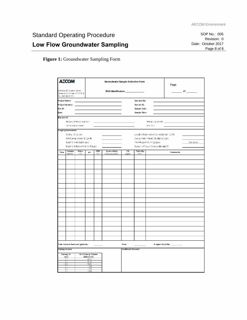
AECOM Environment
Standard Operating Procedure
Low Flow Groundwater Sampling
SOP No.: 005
Revision: 0
Date: October 2017
Page 8 of 8
Figure 1: Groundwater Sampling Form

CCR Groundwater Monitoring System Report Basin Electric Power Cooperative Laramie River Station
Prepared for: Basin Electric Power Cooperative AECOM1
Geoff WebbSenior Project ManagerT: 303.740.3916M: 303.885.0962E: [email protected]
AECOM6200 South Quebec StreetGreenwood Village, CO 80111aecom.com