Embed Size (px)
Citation preview
Coastal Carolina University C-805-15
University Place Dining Hall H17-9606-MJ
Construction Documents July 25, 2016
PATHWAYS FOR COMMUNICATIONS SYSTEMS 270528-1
SECTION 270528 - PATHWAYS FOR COMMUNICATIONS SYSTEMS
PART 1 - GENERAL
1.1 RELATED DOCUMENTS
A. Drawings and general provisions of the Contract, including General and Supplementary
Conditions and Division 01 Specification Sections, apply to this Section.
1.2 SUMMARY
A. Section Includes:
1. Metal conduits and fittings.
2. Metal wireways and auxiliary gutters.
3. Hooks
4. Cabletray
5. Boxes, enclosures, and cabinets.
B. Related Requirements:
1. Section 26 05 43 "Underground Ducts and Raceways for Electrical Systems" for exterior
ductbanks, manholes, and underground utility construction.
2. Section 26 05 33 "Raceways and Boxes for Electrical Systems" for conduits, wireways,
surface raceways, boxes, enclosures, cabinets, handholes, and faceplate adapters serving
electrical systems.
1.3 DEFINITIONS
A. ARC: Aluminum rigid conduit.
B. GRC: Galvanized rigid steel conduit.
C. IMC: Intermediate metal conduit.
1.4 ACTION SUBMITTALS
A. Product Data: For surface pathways, wireways and fittings, floor boxes, hinged-cover
enclosures, and cabinets.
B. Shop Drawings: For custom enclosures and cabinets. Include plans, elevations, sections, and
attachment details.
Coastal Carolina University C-805-15
University Place Dining Hall H17-9606-MJ
Construction Documents July 25, 2016
PATHWAYS FOR COMMUNICATIONS SYSTEMS 270528-2
1.5 INFORMATIONAL SUBMITTALS
A. Source quality-control reports.
PART 2 - PRODUCTS
2.1 METAL CONDUITS AND FITTINGS
A. Manufacturers: Subject to compliance with requirements, provide products by one of the
following:
1. AFC Cable Systems, Inc.
2. Allied Tube & Conduit; a Tyco International Ltd. Co.
3. Anamet Electrical, Inc.
4. Electri-Flex Company.
5. O-Z/Gedney; a brand of EGS Electrical Group.
6. Picoma Industries; Subsidiary of Mueller Water Products, Inc.
7. Republic Conduit.
8. Robroy Industries.
9. Southwire Company.
10. Thomas & Betts Corporation.
11. Western Tube and Conduit Corporation.
12. Wheatland Tube Company; a division of John Maneely Company.
B. General Requirements for Metal Conduits and Fittings:
1. Listed and labeled as defined in NFPA 70, by a qualified testing agency, and marked for
intended location and application.
2. Comply with TIA-569-B.
C. GRC: Comply with ANSI C80.1 and UL 6.
D. ARC: Comply with ANSI C80.5 and UL 6A.
E. IMC: Comply with ANSI C80.6 and UL 1242.
F. PVC-Coated Steel Conduit: PVC-coated rigid steel conduit.
1. Comply with NEMA RN 1.
2. Coating Thickness: 0.040 inch, minimum.
G. EMT: Comply with ANSI C80.3 and UL 797.
H. Fittings for Metal Conduit: Comply with NEMA FB 1 and UL 514B.
1. Fittings for EMT:
a. Material: Steel.
b. Type: Compression.
2. Expansion Fittings: PVC or steel to match conduit type, complying with UL-467, rated
for environmental conditions where installed, and including flexible external bonding
jumper.
Coastal Carolina University C-805-15
University Place Dining Hall H17-9606-MJ
Construction Documents July 25, 2016
PATHWAYS FOR COMMUNICATIONS SYSTEMS 270528-3
3. Coating for Fittings for PVC-Coated Conduit: Minimum thickness of 0.040 inch, with
overlapping sleeves protecting threaded joints.
I. Joint Compound for IMC, GRC, or ARC: Approved, as defined in NFPA 70, by authorities
having jurisdiction for use in conduit assemblies, and compounded for use to lubricate and
protect threaded conduit joints from corrosion and to enhance their conductivity.
2.2 BOXES, ENCLOSURES, AND CABINETS
A. Manufacturers: Subject to compliance with requirements, provide products by one of the
following:
1. Adalet.
2. Cooper Technologies Company; Cooper Crouse-Hinds.
3. EGS/Appleton Electric.
4. Erickson Electrical Equipment Company.
5. Hoffman; a Pentair company.
6. Hubbell Incorporated; Killark Division.
7. Lamson & Sessions; Carlon Electrical Products.
8. Milbank Manufacturing Co.
9. Molex; Woodhead Brand.
10. Mono-Systems, Inc.
11. O-Z/Gedney; a brand of EGS Electrical Group.
12. RACO; a Hubbell company.
13. Robroy Industries.
14. Spring City Electrical Manufacturing Company.
15. Stahlin Non-Metallic Enclosures; a division of Robroy Industries.
16. Thomas & Betts Corporation.
17. Wiremold / Legrand.
B. General Requirements for Boxes, Enclosures, and Cabinets:
1. Comply with TIA-569-B.
2. Boxes, enclosures and cabinets installed in wet locations shall be listed for use in wet
locations.
C. Sheet-Metal Outlet and Device Boxes: Comply with NEMA OS 1 and UL 514A.
D. Cast-Metal Outlet and Device Boxes: Comply with NEMA FB 1, ferrous alloy, Type FD, with
gasketed cover.
E. Box extensions used to accommodate new building finishes shall be of same material as
recessed box.
F. Small Sheet Metal Pull and Junction Boxes: NEMA OS 1.
G. Cast-Metal Access, Pull, and Junction Boxes: Comply with NEMA FB 1 and UL 1773, cast
aluminum with gasketed cover.
H. Device Box Dimensions: 4 inches square by 2-1/8 inches deep unless otherwise noted.
Coastal Carolina University C-805-15
University Place Dining Hall H17-9606-MJ
Construction Documents July 25, 2016
PATHWAYS FOR COMMUNICATIONS SYSTEMS 270528-4
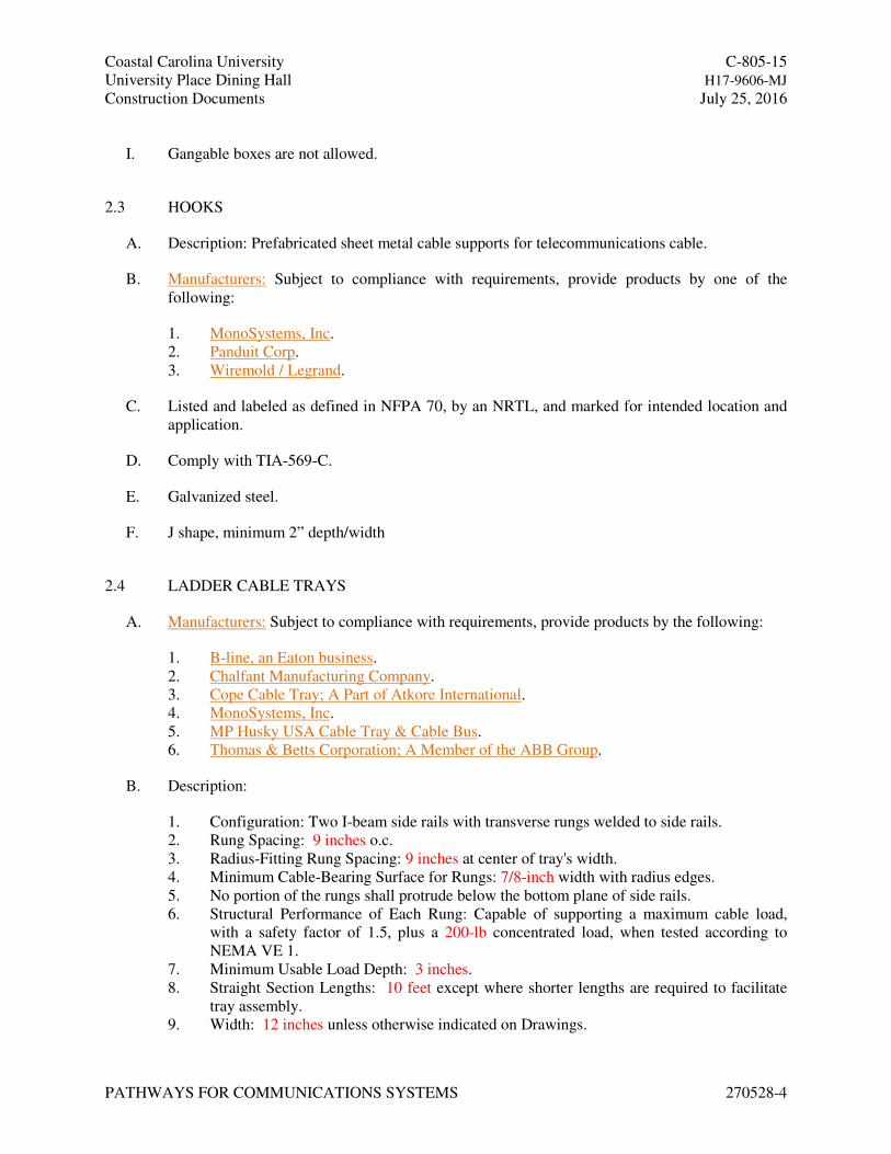
I. Gangable boxes are not allowed.
2.3 HOOKS
A. Description: Prefabricated sheet metal cable supports for telecommunications cable.
B. Manufacturers: Subject to compliance with requirements, provide products by one of the
following:
1. MonoSystems, Inc.
2. Panduit Corp.
3. Wiremold / Legrand.
C. Listed and labeled as defined in NFPA 70, by an NRTL, and marked for intended location and
application.
D. Comply with TIA-569-C.
E. Galvanized steel.
F. J shape, minimum 2” depth/width
2.4 LADDER CABLE TRAYS
A. Manufacturers: Subject to compliance with requirements, provide products by the following:
1. B-line, an Eaton business.
2. Chalfant Manufacturing Company.
3. Cope Cable Tray; A Part of Atkore International.
4. MonoSystems, Inc.
5. MP Husky USA Cable Tray & Cable Bus.
6. Thomas & Betts Corporation; A Member of the ABB Group.
B. Description:
1. Configuration: Two I-beam side rails with transverse rungs welded to side rails.
2. Rung Spacing: 9 inches o.c.
3. Radius-Fitting Rung Spacing: 9 inches at center of tray's width.
4. Minimum Cable-Bearing Surface for Rungs: 7/8-inch width with radius edges.
5. No portion of the rungs shall protrude below the bottom plane of side rails.
6. Structural Performance of Each Rung: Capable of supporting a maximum cable load,
with a safety factor of 1.5, plus a 200-lb concentrated load, when tested according to
NEMA VE 1.
7. Minimum Usable Load Depth: 3 inches.
8. Straight Section Lengths: 10 feet except where shorter lengths are required to facilitate
tray assembly.
9. Width: 12 inches unless otherwise indicated on Drawings.
Coastal Carolina University C-805-15
University Place Dining Hall H17-9606-MJ
Construction Documents July 25, 2016
PATHWAYS FOR COMMUNICATIONS SYSTEMS 270528-5
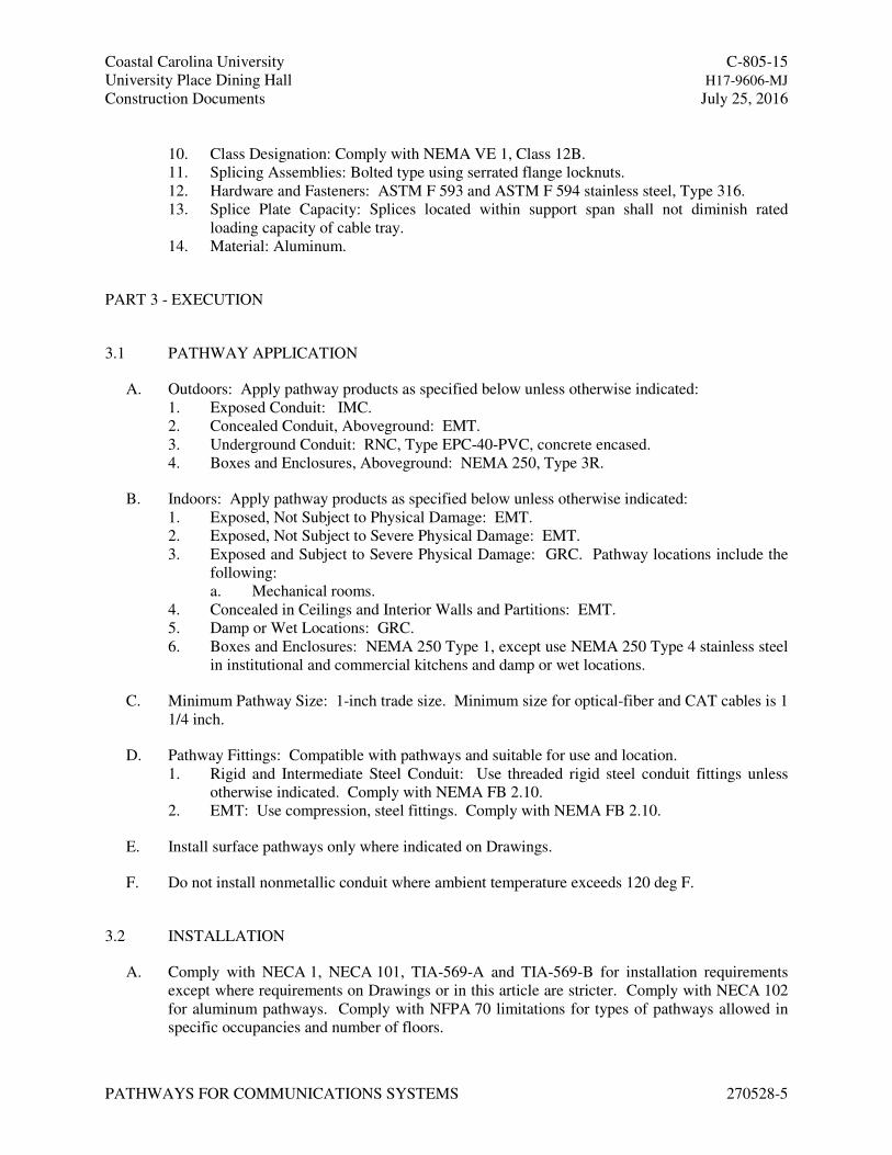
10. Class Designation: Comply with NEMA VE 1, Class 12B.
11. Splicing Assemblies: Bolted type using serrated flange locknuts.
12. Hardware and Fasteners: ASTM F 593 and ASTM F 594 stainless steel, Type 316.
13. Splice Plate Capacity: Splices located within support span shall not diminish rated
loading capacity of cable tray.
14. Material: Aluminum.
PART 3 - EXECUTION
3.1 PATHWAY APPLICATION
A. Outdoors: Apply pathway products as specified below unless otherwise indicated:
1. Exposed Conduit: IMC.
2. Concealed Conduit, Aboveground: EMT.
3. Underground Conduit: RNC, Type EPC-40-PVC, concrete encased.
4. Boxes and Enclosures, Aboveground: NEMA 250, Type 3R.
B. Indoors: Apply pathway products as specified below unless otherwise indicated:
1. Exposed, Not Subject to Physical Damage: EMT.
2. Exposed, Not Subject to Severe Physical Damage: EMT.
3. Exposed and Subject to Severe Physical Damage: GRC. Pathway locations include the
following:
a. Mechanical rooms.
4. Concealed in Ceilings and Interior Walls and Partitions: EMT.
5. Damp or Wet Locations: GRC.
6. Boxes and Enclosures: NEMA 250 Type 1, except use NEMA 250 Type 4 stainless steel
in institutional and commercial kitchens and damp or wet locations.
C. Minimum Pathway Size: 1-inch trade size. Minimum size for optical-fiber and CAT cables is 1
1/4 inch.
D. Pathway Fittings: Compatible with pathways and suitable for use and location.
1. Rigid and Intermediate Steel Conduit: Use threaded rigid steel conduit fittings unless
otherwise indicated. Comply with NEMA FB 2.10.
2. EMT: Use compression, steel fittings. Comply with NEMA FB 2.10.
E. Install surface pathways only where indicated on Drawings.
F. Do not install nonmetallic conduit where ambient temperature exceeds 120 deg F.
3.2 INSTALLATION
A. Comply with NECA 1, NECA 101, TIA-569-A and TIA-569-B for installation requirements
except where requirements on Drawings or in this article are stricter. Comply with NECA 102
for aluminum pathways. Comply with NFPA 70 limitations for types of pathways allowed in
specific occupancies and number of floors.
Coastal Carolina University C-805-15
University Place Dining Hall H17-9606-MJ
Construction Documents July 25, 2016
PATHWAYS FOR COMMUNICATIONS SYSTEMS 270528-6
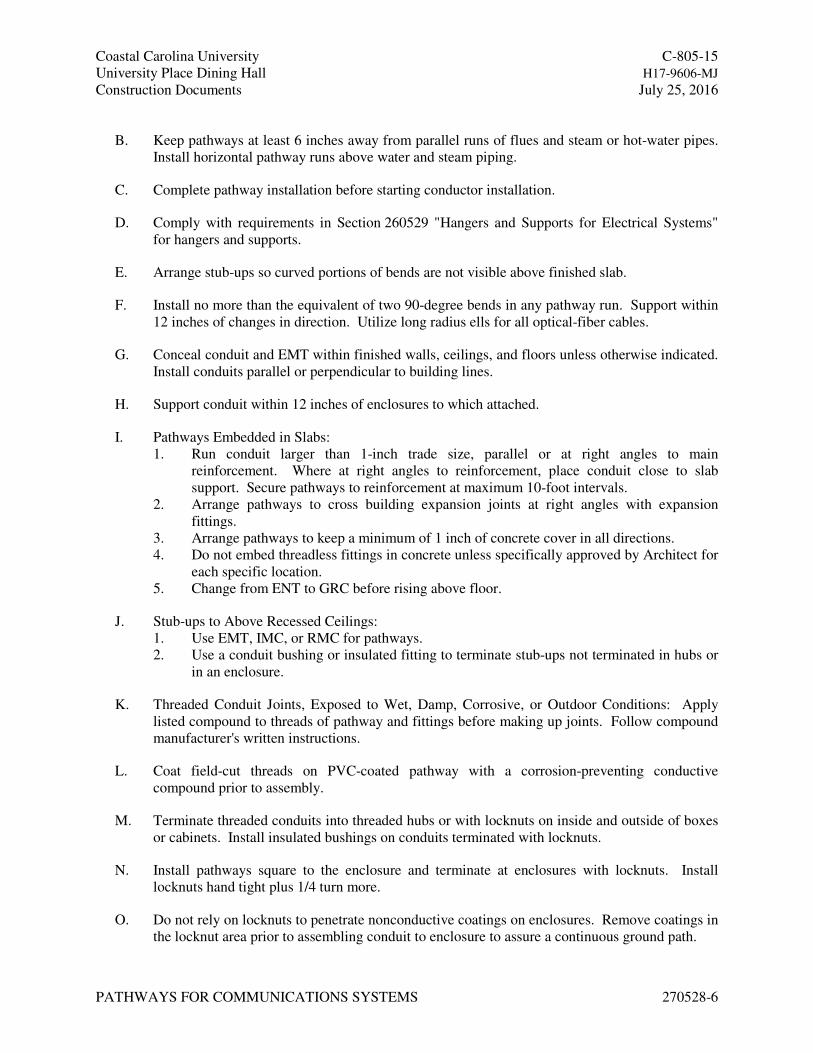
B. Keep pathways at least 6 inches away from parallel runs of flues and steam or hot-water pipes.
Install horizontal pathway runs above water and steam piping.
C. Complete pathway installation before starting conductor installation.
D. Comply with requirements in Section 260529 "Hangers and Supports for Electrical Systems"
for hangers and supports.
E. Arrange stub-ups so curved portions of bends are not visible above finished slab.
F. Install no more than the equivalent of two 90-degree bends in any pathway run. Support within
12 inches of changes in direction. Utilize long radius ells for all optical-fiber cables.
G. Conceal conduit and EMT within finished walls, ceilings, and floors unless otherwise indicated.
Install conduits parallel or perpendicular to building lines.
H. Support conduit within 12 inches of enclosures to which attached.
I. Pathways Embedded in Slabs:
1. Run conduit larger than 1-inch trade size, parallel or at right angles to main
reinforcement. Where at right angles to reinforcement, place conduit close to slab
support. Secure pathways to reinforcement at maximum 10-foot intervals.
2. Arrange pathways to cross building expansion joints at right angles with expansion
fittings.
3. Arrange pathways to keep a minimum of 1 inch of concrete cover in all directions.
4. Do not embed threadless fittings in concrete unless specifically approved by Architect for
each specific location.
5. Change from ENT to GRC before rising above floor.
J. Stub-ups to Above Recessed Ceilings:
1. Use EMT, IMC, or RMC for pathways.
2. Use a conduit bushing or insulated fitting to terminate stub-ups not terminated in hubs or
in an enclosure.
K. Threaded Conduit Joints, Exposed to Wet, Damp, Corrosive, or Outdoor Conditions: Apply
listed compound to threads of pathway and fittings before making up joints. Follow compound
manufacturer's written instructions.
L. Coat field-cut threads on PVC-coated pathway with a corrosion-preventing conductive
compound prior to assembly.
M. Terminate threaded conduits into threaded hubs or with locknuts on inside and outside of boxes
or cabinets. Install insulated bushings on conduits terminated with locknuts.
N. Install pathways square to the enclosure and terminate at enclosures with locknuts. Install
locknuts hand tight plus 1/4 turn more.
O. Do not rely on locknuts to penetrate nonconductive coatings on enclosures. Remove coatings in
the locknut area prior to assembling conduit to enclosure to assure a continuous ground path.
Coastal Carolina University C-805-15
University Place Dining Hall H17-9606-MJ
Construction Documents July 25, 2016
PATHWAYS FOR COMMUNICATIONS SYSTEMS 270528-7
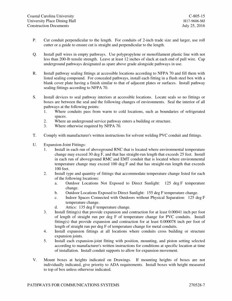
P. Cut conduit perpendicular to the length. For conduits of 2-inch trade size and larger, use roll
cutter or a guide to ensure cut is straight and perpendicular to the length.
Q. Install pull wires in empty pathways. Use polypropylene or monofilament plastic line with not
less than 200-lb tensile strength. Leave at least 12 inches of slack at each end of pull wire. Cap
underground pathways designated as spare above grade alongside pathways in use.
R. Install pathway sealing fittings at accessible locations according to NFPA 70 and fill them with
listed sealing compound. For concealed pathways, install each fitting in a flush steel box with a
blank cover plate having a finish similar to that of adjacent plates or surfaces. Install pathway
sealing fittings according to NFPA 70.
S. Install devices to seal pathway interiors at accessible locations. Locate seals so no fittings or
boxes are between the seal and the following changes of environments. Seal the interior of all
pathways at the following points:
1. Where conduits pass from warm to cold locations, such as boundaries of refrigerated
spaces.
2. Where an underground service pathway enters a building or structure.
3. Where otherwise required by NFPA 70.
T. Comply with manufacturer's written instructions for solvent welding PVC conduit and fittings.
U. Expansion-Joint Fittings:
1. Install in each run of aboveground RNC that is located where environmental temperature
change may exceed 30 deg F, and that has straight-run length that exceeds 25 feet. Install
in each run of aboveground RMC and EMT conduit that is located where environmental
temperature change may exceed 100 deg F and that has straight-run length that exceeds
100 feet.
2. Install type and quantity of fittings that accommodate temperature change listed for each
of the following locations:
a. Outdoor Locations Not Exposed to Direct Sunlight: 125 deg F temperature
change.
b. Outdoor Locations Exposed to Direct Sunlight: 155 deg F temperature change.
c. Indoor Spaces Connected with Outdoors without Physical Separation: 125 deg F
temperature change.
d. Attics: 135 deg F temperature change.
3. Install fitting(s) that provide expansion and contraction for at least 0.00041 inch per foot
of length of straight run per deg F of temperature change for PVC conduits. Install
fitting(s) that provide expansion and contraction for at least 0.000078 inch per foot of
length of straight run per deg F of temperature change for metal conduits.
4. Install expansion fittings at all locations where conduits cross building or structure
expansion joints.
5. Install each expansion-joint fitting with position, mounting, and piston setting selected
according to manufacturer's written instructions for conditions at specific location at time
of installation. Install conduit supports to allow for expansion movement.
V. Mount boxes at heights indicated on Drawings. If mounting heights of boxes are not
individually indicated, give priority to ADA requirements. Install boxes with height measured
to top of box unless otherwise indicated.
Coastal Carolina University C-805-15
University Place Dining Hall H17-9606-MJ
Construction Documents July 25, 2016
PATHWAYS FOR COMMUNICATIONS SYSTEMS 270528-8
W. Recessed Boxes in Masonry Walls: Saw-cut opening for box in center of cell of masonry block,
and install box flush with surface of wall. Prepare block surface to provide a flat surface for a
raintight connection between box and cover plate or supported equipment and box.
X. Horizontally separate boxes mounted on opposite sides of walls so they are not in the same
vertical channel.
Y. Support boxes of three gangs or more from more than one side by spanning two framing
members or mounting on brackets specifically designed for the purpose.
Z. Fasten junction and pull boxes to or support from building structure. Do not support boxes by
conduits.
AA. Set metal floor boxes level and flush with finished floor surface.
BB. Set nonmetallic floor boxes level. Trim after installation to fit flush with finished floor surface.
3.3 CABLE TRAY INSTALLATION
A. Install cable trays according to NEMA FG 1.
B. Install cable trays as a complete system, including fasteners, hold-down clips, support systems,
barrier strips, adjustable horizontal and vertical splice plates, elbows, reducers, tees, crosses,
cable dropouts, adapters, covers, and bonding.
C. Install cable trays so that the tray is accessible for cable installation and all splices are accessible
for inspection and adjustment.
D. Remove burrs and sharp edges from cable trays.
E. Join aluminum cable tray with splice plates; use four square neck-carriage bolts and locknuts.
F. Fasten cable tray supports to building structure and install seismic restraints.
G. Construct supports from channel members, threaded rods, and other appurtenances furnished by
cable tray manufacturer. Arrange supports in trapeze or wall-bracket form as required by
application.
H. Support bus assembly to prevent twisting from eccentric loading.
I. Install center-hung supports for single-rail trays designed for 60 versus 40 percent eccentric
loading condition, with a safety factor of 3.
J. Locate and install supports according to NEMA FG 1. Do not install more than one cable tray
splice between supports.
Coastal Carolina University C-805-15
University Place Dining Hall H17-9606-MJ
Construction Documents July 25, 2016
PATHWAYS FOR COMMUNICATIONS SYSTEMS 270528-9
K. Make connections to equipment with flanged fittings fastened to cable trays and to equipment.
Support cable trays independent of fittings. Do not carry weight of cable trays on equipment
enclosure.
L. Make changes in direction and elevation using manufacturer's recommended fittings.
M. Make cable tray connections using manufacturer's recommended fittings.
N. Seal penetrations through fire and smoke barriers. Comply with requirements in Section 078413
"Penetration Firestopping."
O. Install capped metal sleeves for future cables through firestop-sealed cable tray penetrations of
fire and smoke barriers.
P. Install cable trays with enough workspace to permit access for installing cables.
Q. Install barriers to separate cables of different systems, such as power, communications, and data
processing; or of different insulation levels, such as 600, 5000, and 15 000 V.
R. Install warning signs in visible locations on or near cable trays after cable tray installation.
3.4 CABLE TRAY GROUNDING
A. Ground cable trays according to NFPA 70 unless additional grounding is specified. Comply
with requirements in Section 260526 "Grounding and Bonding for Electrical Systems."
B. Cable trays with communications cable shall be bonded together with splice plates listed for
grounding purposes or with listed bonding jumpers.
C. Cable trays with control conductors shall be bonded together with splice plates listed for
grounding purposes or with listed bonding jumpers.
D. When using epoxy- or powder-coat painted cable trays as a grounding conductor, completely
remove coating at all splice contact points or ground connector attachment. After completing
splice-to-grounding bolt attachment, repair the coated surfaces with coating materials
recommended by cable tray manufacturer.
E. Bond cable trays to power source for cables contained within with bonding conductors sized
according to NFPA 70, Article 250.122, "Size of Equipment Grounding Conductors."
3.5 CABLE INSTALLATION
A. Install cables only when each cable tray run has been completed and inspected.
B. Fasten cables on horizontal runs with cable clamps or cable ties according to NEMA VE 2.
Tighten clamps only enough to secure the cable, without indenting the cable jacket. Install cable
ties with a tool that includes an automatic pressure-limiting device.
Coastal Carolina University C-805-15
University Place Dining Hall H17-9606-MJ
Construction Documents July 25, 2016
PATHWAYS FOR COMMUNICATIONS SYSTEMS 270528-10
C. Fasten cables on vertical runs to cable trays every 18 inches (450 mm).
D. Fasten and support cables that pass from one cable tray to another or drop from cable trays to
equipment enclosures. Fasten cables to the cable tray at the point of exit and support cables
independent of the enclosure. The cable length between cable trays or between cable tray and
enclosure shall be no more than 72 inches (1800 mm).
3.6 SLEEVE AND SLEEVE-SEAL INSTALLATION FOR COMMUNICATIONS
PENETRATIONS
A. Install sleeves and sleeve seals at penetrations of exterior floor and wall assemblies. Comply
with requirements in Section 270544 "Sleeves and Sleeve Seals for Communications Pathways
and Cabling."
3.7 FIRESTOPPING
A. Install firestopping at penetrations of fire-rated floor and wall assemblies. Comply with
requirements in Section 078413 "Penetration Firestopping."
3.8 PROTECTION
A. Protect coatings, finishes, and cabinets from damage or deterioration.
1. Repair damage to galvanized finishes with zinc-rich paint recommended by
manufacturer.
2. Repair damage to PVC coatings or paint finishes with matching touchup coating
recommended by manufacturer.
END OF SECTION 270528
Coastal Carolina University C-805-15
University Place Dining Hall H17-9606-MJ
Construction Documents July 25, 2016
SLEEVES AND SLEEVE SEALS FOR COMMUNICATIONS 270544-1
PATHWAYS AND CABLING
SECTION 270544 - SLEEVES AND SLEEVE SEALS FOR COMMUNICATIONS PATHWAYS AND
CABLING
PART 1 - GENERAL
1.1 RELATED DOCUMENTS
A. Drawings and general provisions of the Contract, including General and Supplementary
Conditions and Division 01 Specification Sections, apply to this Section.
1.2 SUMMARY
A. Section Includes:
1. Sleeves for pathway and cable penetration of non-fire-rated construction walls and floors.
2. Sleeve-seal systems.
3. Sleeve-seal fittings.
4. Grout.
5. Silicone sealants.
B. Related Requirements:
1. Section 078413 "Penetration Firestopping" for penetration firestopping installed in fire-
resistance-rated walls, horizontal assemblies, and smoke barriers, with and without
penetrating items.
1.3 ACTION SUBMITTALS
A. Product Data: For each type of product.
PART 2 - PRODUCTS
2.1 SLEEVES
A. Wall Sleeves:
1. Steel Pipe Sleeves: ASTM A 53/A 53M, Type E, Grade B, Schedule 40, zinc coated,
plain ends.
2. Cast-Iron Pipe Sleeves: Cast or fabricated "wall pipe," equivalent to ductile-iron pressure
pipe, with plain ends and integral waterstop unless otherwise indicated.
B. Sleeves for Conduits Penetrating Non-Fire-Rated Gypsum Board Assemblies: Galvanized-steel
sheet; 0.0239-inch minimum thickness; round tube closed with welded longitudinal joint, with
tabs for screw-fastening the sleeve to the board.
C. PVC-Pipe Sleeves: ASTM D 1785, Schedule 40.
Coastal Carolina University C-805-15
University Place Dining Hall H17-9606-MJ
Construction Documents July 25, 2016
SLEEVES AND SLEEVE SEALS FOR COMMUNICATIONS 270544-2
PATHWAYS AND CABLING
D. Molded-PVC Sleeves: With nailing flange for attaching to wooden forms.
E. Molded-PE or -PP Sleeves: Removable, tapered-cup shaped, and smooth outer surface with
nailing flange for attaching to wooden forms.
F. Sleeves for Rectangular Openings:
1. Material: Galvanized-steel sheet.
2. Minimum Metal Thickness:
a. For sleeve cross-section rectangle perimeter less than 50 inches and with no side
larger than 16 inches, thickness shall be 0.052 inch.
b. For sleeve cross-section rectangle perimeter 50 inches or more and one or more
sides larger than 16 inches, thickness shall be 0.138 inch.
2.2 SLEEVE-SEAL SYSTEMS
A. Description: Modular sealing device, designed for field assembly, to fill annular space between
sleeve and pathway or cable.
1. Manufacturers: Subject to compliance with requirements, provide products by the
following:
a. Advance Products & Systems, Inc.
b. CALPICO, Inc.
c. Metraflex Company (The).
d. Pipeline Seal and Insulator, Inc.
e. Proco Products, Inc.
2. Sealing Elements: EPDM rubber interlocking links shaped to fit surface of pipe. Include
type and number required for pipe material and size of pipe.
3. Pressure Plates: Carbon steel.
4. Connecting Bolts and Nuts: Carbon steel, with corrosion-resistant coating, of length
required to secure pressure plates to sealing elements.
2.3 SLEEVE-SEAL FITTINGS
A. Description: Manufactured plastic, sleeve-type, waterstop assembly made for embedding in
concrete slab or wall. Unit shall have plastic or rubber waterstop collar with center opening to
match piping OD.
1. Manufacturers: Subject to compliance with requirements, provide products by the
following:
a. Presealed Systems.
2.4 GROUT
A. Description: Nonshrink; recommended for interior and exterior sealing openings in non-fire-
rated walls or floors.
B. Standard: ASTM C 1107/C 1107M, Grade B, post-hardening and volume-adjusting, dry,
hydraulic-cement grout.
Coastal Carolina University C-805-15
University Place Dining Hall H17-9606-MJ
Construction Documents July 25, 2016
SLEEVES AND SLEEVE SEALS FOR COMMUNICATIONS 270544-3
PATHWAYS AND CABLING
C. Design Mix: 5000-psi, 28-day compressive strength.
D. Packaging: Premixed and factory packaged.
2.5 SILICONE SEALANTS
A. Silicone Sealants: Single-component, silicone-based, neutral-curing elastomeric sealants of
grade indicated below.
1. Grade: Pourable (self-leveling) formulation for openings in floors and other horizontal
surfaces that are not fire rated.
2. Sealant shall have VOC content of 250 g/L or less when calculated according to
40 CFR 59, Subpart D (EPA Method 24).
B. Silicone Foams: Multicomponent, silicone-based liquid elastomers that, when mixed, expand
and cure in place to produce a flexible, nonshrinking foam.
PART 3 - EXECUTION
3.1 SLEEVE INSTALLATION FOR NON-FIRE-RATED ELECTRICAL PENETRATIONS
A. Comply with NECA 1.
B. Comply with NEMA VE 2 for cable tray and cable penetrations.
C. Sleeves for Conduits Penetrating Above-Grade Non-Fire-Rated Concrete and Masonry-Unit
Floors and Walls:
1. Interior Penetrations of Non-Fire-Rated Walls and Floors:
a. Seal annular space between sleeve and pathway or cable, using joint sealant
appropriate for size, depth, and location of joint. Comply with requirements in
Section 07 92 00 "Joint Sealants."
b. Seal space outside of sleeves with mortar or grout. Pack sealing material solidly
between sleeve and wall so no voids remain. Tool exposed surfaces smooth;
protect material while curing.
2. Use pipe sleeves unless penetration arrangement requires rectangular sleeved opening.
3. Size pipe sleeves to provide 1/4-inch annular clear space between sleeve and pathway or
cable unless sleeve seal is to be installed or unless seismic criteria require different
clearance.
4. Install sleeves for wall penetrations unless core-drilled holes or formed openings are
used. Install sleeves during erection of walls. Cut sleeves to length for mounting flush
with both surfaces of walls. Deburr after cutting.
5. Install sleeves for floor penetrations. Extend sleeves installed in floors 2 inches above
finished floor level. Install sleeves during erection of floors.
D. Sleeves for Conduits Penetrating Non-Fire-Rated Gypsum Board Assemblies:
1. Use circular metal sleeves unless penetration arrangement requires rectangular sleeved
opening.
Coastal Carolina University C-805-15
University Place Dining Hall H17-9606-MJ
Construction Documents July 25, 2016
SLEEVES AND SLEEVE SEALS FOR COMMUNICATIONS 270544-4
PATHWAYS AND CABLING
2. Seal space outside of sleeves with approved joint compound for gypsum board
assemblies.
E. Roof-Penetration Sleeves: Seal penetration of individual pathways and cables with flexible
boot-type flashing units applied in coordination with roofing work.
F. Aboveground, Exterior-Wall Penetrations: Seal penetrations using cast-iron pipe sleeves and
mechanical sleeve seals. Select sleeve size to allow for 1-inch annular clear space between pipe
and sleeve for installing mechanical sleeve seals.
G. Underground, Exterior-Wall and Floor Penetrations: Install cast-iron pipe sleeves. Size sleeves
to allow for 1-inch annular clear space between pathway or cable and sleeve for installing
sleeve-seal system.
3.2 SLEEVE-SEAL-SYSTEM INSTALLATION
A. Install sleeve-seal systems in sleeves in exterior concrete walls and slabs-on-grade at pathway
entries into building.
B. Install type and number of sealing elements recommended by manufacturer for pathway or
cable material and size. Position pathway or cable in center of sleeve. Assemble mechanical
sleeve seals and install in annular space between pathway or cable and sleeve. Tighten bolts
against pressure plates that cause sealing elements to expand and make watertight seal.
3.3 SLEEVE-SEAL-FITTING INSTALLATION
A. Install sleeve-seal fittings in new walls and slabs as they are constructed.
B. Assemble fitting components of length to be flush with both surfaces of concrete slabs and
walls. Position waterstop flange to be centered in concrete slab or wall.
C. Secure nailing flanges to concrete forms.
D. Using grout, seal the space around outside of sleeve-seal fittings.
END OF SECTION 270544
Coastal Carolina University C-805-15
University Place Dining Hall H17-9606-MJ
Construction Documents July 25, 2016
COMMUNICATIONS EQUIPMENT ROOM FITTINGS 271100 - 1
SECTION 271100 - COMMUNICATIONS EQUIPMENT ROOM FITTINGS
PART 1 - GENERAL
1.1 RELATED DOCUMENTS
A. Drawings and general provisions of the Contract, including General and Supplementary
Conditions and Division 01 Specification Sections, apply to this Section.
1.2 SUMMARY
A. Section Includes:
1. Telecommunications mounting elements.
2. Backboards.
3. Telecommunications equipment racks and cabinets.
4. Grounding.
B. Related Requirements:
1. Section 270528 "Pathways For Communications Systems" for cable trays, J-Hooks and
accessories.
2. Section 271500 "Communications Horizontal Cabling" for voice and data cabling
associated with system panels and devices.
1.3 DEFINITIONS
A. BICSI: Building Industry Consulting Service International.
B. LAN: Local area network.
C. RCDD: Registered Communications Distribution Designer.
1.4 ACTION SUBMITTALS
A. Product Data: For each type of product.
1. Include construction details, material descriptions, dimensions of individual components
and profiles, and finishes for equipment racks and cabinets.
2. Include rated capacities, operating characteristics, electrical characteristics, and furnished
specialties and accessories.
B. Shop Drawings: For communications equipment room fittings. Include plans, elevations,
sections, details, and attachments to other work.
1. Detail equipment assemblies and indicate dimensions, weights, loads, required
clearances, method of field assembly, components, and location and size of each field
connection.
Coastal Carolina University C-805-15
University Place Dining Hall H17-9606-MJ
Construction Documents July 25, 2016
COMMUNICATIONS EQUIPMENT ROOM FITTINGS 271100 - 2
2. Equipment Racks and Cabinets: Include workspace requirements and access for cable
connections.
3. Grounding: Indicate location of grounding bus bar and its mounting detail showing
standoff insulators and wall mounting brackets.
1.5 INFORMATIONAL SUBMITTALS
A. Qualification Data: For Installer, qualified layout technician, installation supervisor, and field
inspector.
B. Seismic Qualification Certificates: For equipment frames from manufacturer.
1. Basis for Certification: Indicate whether withstand certification is based on actual test of
assembled components or on calculation.
2. Dimensioned Outline Drawings of Equipment Unit: Identify center of gravity and locate
and describe mounting and anchorage provisions. Base certification on the maximum
number of components capable of being mounted in each rack type. Identify components
on which certification is based.
3. Detailed description of equipment anchorage devices on which the certification is based
and their installation requirements.
1.6 QUALITY ASSURANCE
A. Installer Qualifications: Cabling Installer must have personnel certified by BICSI on staff.
1. Layout Responsibility: Preparation of Shop Drawings, Cabling Administration
Drawings, and field testing program development by an AMP-authorized ND&I
contractor or equivalent certification and reviewed by an RCDD.
2. Installation Supervision: Installation shall be under the direct supervision of AMP-
authorized ND&I contractor or equivalent certification who shall be present at all times
when Work of this Section is performed at Project site.
3. Field Inspector: Currently registered by BICSI as RCDD to perform the on-site
inspection.
PART 2 - PRODUCTS
2.1 PERFORMANCE REQUIREMENTS
A. Seismic Performance: Equipment frames shall withstand the effects of earthquake motions
determined according to ASCE/SEI 7.
1. The term "withstand" means "the unit will remain in place without separation of any parts
from the device when subjected to the seismic forces specified and the unit will be fully
operational after the seismic event."
Coastal Carolina University C-805-15
University Place Dining Hall H17-9606-MJ
Construction Documents July 25, 2016
COMMUNICATIONS EQUIPMENT ROOM FITTINGS 271100 - 3
2.2 BACKBOARDS
A. Backboards: Plywood, fire-retardant treated, 3/4 by 48 by 96 inches. Comply with
requirements for plywood backing panels specified in Section 061000 "Rough Carpentry."
2.3 EQUIPMENT FRAMES
A. Basis-of-Design Product: Subject to compliance with requirements, provide Tyco Electronics
Corporation; AMP Products.
B. General Frame Requirements:
1. Distribution Frames: Freestanding and wall-mounting, modular-steel units designed for
telecommunications terminal support and coordinated with dimensions of units to be
supported.
2. Module Dimension: Width compatible with EIA 310-D standard, 19-inch panel
mounting.
3. Finish: Manufacturer's standard, baked-polyester powder coat.
C. Floor-Mounted Racks (Commscope/AMP #1933559-1): Modular-type, steel construction, two
post 84-inches high.
1. Vertical and horizontal cable management channels, top and bottom cable troughs,
grounding lug, and a power strip.
D. Cable Management for Equipment Frames:
1. Metal, with integral wire retaining fingers.
2. Baked-polyester powder coat finish.
3. Vertical cable management panels (Commscopte/AMP #1933534-1) shall have front and
rear channels, with covers.
4. Provide horizontal crossover cable manager (Commscope/AMP #1933567-1) at the top
of each relay rack, with a minimum height of two rack units each.
5. Each patch panel shall be separated vertically on the rack by a 2U horizontal finger duct
cable management panel.
2.4 POWER STRIPS
A. Power Strips: Comply with UL 1363.
1. Listed and labeled as defined in NFPA 70, by a qualified testing agency, and marked for
intended location and application.
2. Rack mounting.
3. Six 20-A, 120-V ac, NEMA WD 6, Configuration 5-20R receptacles.
4. LED indicator lights for power and protection status.
5. LED indicator lights for reverse polarity and open outlet ground.
6. Circuit Breaker and Thermal Fusing: When protection is lost, circuit opens and cannot
be reset.
7. Cord connected with 15-foot line cord.
8. Rocker-type on-off switch, illuminated when in on position.
9. Peak Single-Impulse Surge Current Rating: 26 kA per phase.
Coastal Carolina University C-805-15
University Place Dining Hall H17-9606-MJ
Construction Documents July 25, 2016
COMMUNICATIONS EQUIPMENT ROOM FITTINGS 271100 - 4
10. Protection modes shall be line to neutral, line to ground, and neutral to ground. UL 1449
clamping voltage for all three modes shall be not more than 330 V.
2.5 GROUNDING
A. Comply with requirements in Section 260526 "Grounding and Bonding for Electrical Systems"
for grounding conductors and connectors.
B. Telecommunications Main Bus Bar:
1. Connectors: Mechanical type, cast silicon bronze, solderless compression-type wire
terminals, and long-barrel, two-bolt connection to ground bus bar.
2. Ground Bus Bar: Copper, minimum 1/4 inch thick by 4 inches wide with 9/32-inch holes
spaced 1-1/8 inches apart.
3. Stand-Off Insulators: Comply with UL 891 for use in switchboards, 600 V. Lexan or
PVC, impulse tested at 5000 V.
C. Comply with J-STD-607-A.
2.6 LABELING
A. Comply with TIA/EIA-606-A and UL 969 for a system of labeling materials, including label
stocks, laminating adhesives, and inks used by label printers.
B. Label each rack front and back. Coordinate labeling standards through shop drawing process.
PART 3 - EXECUTION
3.1 ENTRANCE FACILITIES
A. Contact telecommunications service provider and arrange for installation of demarcation point,
protected entrance terminals, and a housing when so directed by service provider.
B. Comply with requirements in Section 270528 "Pathways for Communications Systems" for
materials and installation requirements for underground pathways.
3.2 INSTALLATION
A. Comply with NECA 1.
B. Comply with BICSI TDMM for layout and installation of communications equipment rooms.
C. Bundle, lace, and train conductors and cables to terminal points without exceeding
manufacturer's limitations on bending radii. Install lacing bars and distribution spools.
Coastal Carolina University C-805-15
University Place Dining Hall H17-9606-MJ
Construction Documents July 25, 2016
COMMUNICATIONS EQUIPMENT ROOM FITTINGS 271100 - 5
D. Coordinate layout and installation of communications equipment with Owner's
telecommunications and LAN equipment and service suppliers. Coordinate service entrance
arrangement with local exchange carrier.
1. Meet jointly with telecommunications and LAN equipment suppliers, local exchange
carrier representatives, and Owner to exchange information and agree on details of
equipment arrangements and installation interfaces.
2. Record agreements reached in meetings and distribute them to other participants.
3. Adjust arrangements and locations of distribution frames, cross-connects, and patch
panels in equipment rooms to accommodate and optimize arrangement and space
requirements of telephone switch and LAN equipment.
4. Adjust arrangements and locations of equipment with distribution frames, cross-connects,
and patch panels of cabling systems of other communications, electronic safety and
security, and related systems that share space in the equipment room.
5. Racks shall be placed in a manner that will allow a minimum of three (3) feet of
clearance from the front and rear mounting surfaces and on one side. The remaining side
shall be no closer than 6” away from a wall. Multiple racks shall be ganged with vertical
management hardware to provide interbay management.
E. Coordinate location of power raceways and receptacles with locations of communications
equipment requiring electrical power to operate.
F. Provide plywood backboard at 4-inches and end at 8-foot, 4-inches above finished floor on
walls within equipment room.
3.3 SLEEVE AND SLEEVE SEAL INSTALLATION FOR ELECTRICAL PENETRATIONS
A. Install sleeves and sleeve seals at penetrations of exterior floor and wall assemblies. Comply
with requirements in Section 270544 "Sleeves and Sleeve Seals for Communications Pathways
and Cabling."
3.4 FIRESTOPPING
A. Comply with requirements in Section 078413 "Penetration Firestopping."
B. Comply with TIA-569-B, Annex A, "Firestopping."
C. Comply with BICSI TDMM, "Firestopping Systems" Article.
3.5 GROUNDING
A. Install grounding according to BICSI TDMM, "Grounding, Bonding, and Electrical Protection"
Chapter.
B. Comply with J-STD-607-A.
Coastal Carolina University C-805-15
University Place Dining Hall H17-9606-MJ
Construction Documents July 25, 2016
COMMUNICATIONS EQUIPMENT ROOM FITTINGS 271100 - 6
C. Locate grounding bus bar to minimize the length of bonding conductors. Fasten to wall
allowing at least 2-inch clearance behind the grounding bus bar. Connect grounding bus bar
with a minimum No. 4 AWG grounding electrode conductor from grounding bus bar to suitable
electrical building ground.
D. Bond metallic equipment to the grounding bus bar, using not smaller than No. 6 AWG
equipment grounding conductor.
1. Bond the shield of shielded cable to the grounding bus bar in communications rooms and
spaces.
3.6 IDENTIFICATION
A. Identify system components, wiring, and cabling complying with TIA/EIA-606-A. Comply
with requirements in Section 260553 "Identification for Electrical Systems."
B. Comply with requirements in Section 099123 "Interior Painting" for painting backboards. For
fire-resistant plywood, do not paint over manufacturer's label.
C. Paint and label colors for equipment identification shall comply with TIA/EIA-606-A for
Class 2 level of administration including optional identification requirements of this standard.
D. Labels shall be preprinted or computer-printed type.
END OF SECTION 271100
Coastal Carolina University C-805-15
University Place Dining Hall H17-9606-MJ
Construction Documents July 25, 2016
COMMUNICATIONS HORIZONTAL CABLING 271500 - 1
SECTION 271500 - COMMUNICATIONS HORIZONTAL CABLING
PART 1 - GENERAL
1.1 RELATED DOCUMENTS
A. Drawings and general provisions of the Contract, including General and Supplementary
Conditions and Division 01 Specification Sections, apply to this Section.
1.2 SUMMARY
A. Section Includes:
1. UTP cabling.
2. Coaxial cable.
3. High definition multimedia interface cable.
4. Cable connecting hardware, patch panels, and cross-connects.
5. Telecommunications outlet/connectors.
6. Cabling system identification products.
B. Related Requirements:
1. Section 270528 “Pathways for Communications Systems” for raceways and boxes for
voice and data cabling.
2. Section 270536 “Cable Trays for Communications Systems” for cable trays for voice and
data cabling.
3. Section 271100 “Communications Equipment Room Fittings” for voice and data
equipment rooms.
4. Section 271300 "Communications Backbone Cabling" for voice and data cabling
associated with system panels and devices
5. Section 280513 "Conductors and Cables for Electronic Safety and Security" for voice and
data cabling associated with system panels and devices.
1.3 DEFINITIONS
A. BICSI: Building Industry Consulting Service International.
B. Cross-Connect: A facility enabling the termination of cable elements and their interconnection
or cross-connection.
C. EMI: Electromagnetic interference.
D. HDMI: High-definition multimedia interface.
E. IDC: Insulation displacement connector.
Coastal Carolina University C-805-15
University Place Dining Hall H17-9606-MJ
Construction Documents July 25, 2016
COMMUNICATIONS HORIZONTAL CABLING 271500 - 2
F. LAN: Local area network.
G. Outlet/Connectors: A connecting device on which horizontal cable or outlet cable terminates.
H. RCDD: Registered Communications Distribution Designer.
I. UTP: Unshielded twisted pair.
1.4 HORIZONTAL CABLING DESCRIPTION
A. Horizontal cable and its connecting hardware provide the means of transporting signals between
the telecommunications outlet/connector and the horizontal cross-connect located in the
communications equipment room. This cabling and its connecting hardware are called a
"permanent link," a term that is used in the testing protocols.
1. TIA/EIA-568-B.1 requires that a minimum of two telecommunications outlet/connectors
be installed for each work area.
2. Horizontal cabling shall contain no more than one transition point or consolidation point
between the horizontal cross-connect and the telecommunications outlet/connector.
3. Bridged taps and splices shall not be installed in the horizontal cabling.
B. The maximum allowable horizontal cable length is 295 feet. This maximum allowable length
does not include an allowance for the length of 16 feet to the workstation equipment or in the
horizontal cross-connect.
1.5 PERFORMANCE REQUIREMENTS
A. General Performance: Horizontal cabling system shall comply with transmission standards in
TIA/EIA-568-B.1 when tested according to test procedures of this standard.
B. Surface-Burning Characteristics: Comply with ASTM E 84; testing by a qualified testing
agency. Identify products with appropriate markings of applicable testing agency.
1. Flame-Spread Index: 25 or less.
2. Smoke-Developed Index: 50 or less.
C. Electrical Components, Devices, and Accessories: Listed and labeled as defined in NFPA 70,
by a qualified testing agency, and marked for intended location and application.
D. Grounding: Comply with J-STD-607-A
1.6 ADMINISTRATIVE REQUIREMENTS
A. Coordinate layout and installation of telecommunications cabling with Owner's
telecommunications and LAN equipment and service suppliers and CCU ITS department.
B. Coordinate telecommunications outlet/connector locations with location of power receptacles at
each work area.
Coastal Carolina University C-805-15
University Place Dining Hall H17-9606-MJ
Construction Documents July 25, 2016
COMMUNICATIONS HORIZONTAL CABLING 271500 - 3
1.7 ACTION SUBMITTALS
A. Product Data: Include for each type of equipment, device, and cable indicated.
B. Shop Drawings:
1. System Labeling Schedules: Electronic copy of labeling schedules, in format selected by
Owner. At a minimum the labeling system shall:
a. Clearly identify all components of the system: racks, cables, panels and outlets.
b. Designate the cables origin and destination and a unique identifier for the cable
within the system.
c. Racks and patch panels shall be labeled to identify the location within the cabling
system infrastructure.
2. Cabling administration drawings and printouts.
3. Wiring diagrams to show typical wiring schematics, including the following:
a. Cross-connects.
b. Patch panels.
c. Patch cords.
4. Cross-connects and patch panels. Detail mounting assemblies, and show elevations and
physical relationship between the installed components.
5. Cable tray layout, showing cable tray route to scale, with relationship between the tray
and adjacent structural, electrical, and mechanical elements. Include the following:
a. Vertical and horizontal offsets and transitions.
b. Clearances for access above and to side of cable trays.
c. Vertical elevation of cable trays above the floor or bottom of ceiling structure.
d. Load calculations to show dead and live loads as not exceeding manufacturer's
rating for tray and its support elements
1.8 INFORMATIONAL SUBMITTALS
A. Qualification Data: For Installer, qualified layout technician, installation supervisor, and field
inspector.
B. Source quality-control reports.
C. Field quality-control reports.
1.9 CLOSEOUT SUBMITTALS
A. Maintenance Data: For splices and connectors to include in maintenance manuals.
B. Field Test Reports: Written reports specified in Part 3. Reports shall reflect the appropriate
labeling scheme.
C. As-Built Drawings: The installing contractor will be provided with two sets of full size
drawings at the start of the project. One set will be designated for as the central location to
document all as-built information as it occurs throughout the project. The central set will be
maintained by the Contractor’s Foreman on a daily basis, and will be available to the technical
Coastal Carolina University C-805-15
University Place Dining Hall H17-9606-MJ
Construction Documents July 25, 2016
COMMUNICATIONS HORIZONTAL CABLING 271500 - 4
representative upon request during the course of the project. Anticipated variations from the
drawings may be for such things as cable routing and actual outlet placement. No variations
will be allowed to the planned termination positions of horizontal and backbone cables, and
grounding conductors unless approved in writing by the Owner.
1. The Contractor shall provide the central drawing set to the Owner at the conclusion of the
project. The marked up drawing set will accurately depict the as-built status of the
system including termination locations, cable routing, and all administration labeling for
the cabling system. In addition, a narrative will be provided that describes any areas of
difficulty encountered during the installation that could potentially cause problems to the
telecommunications system.
2. The Contractor shall provide an updated set of laminated as-built drawings and electronic
files
1.10 QUALITY ASSURANCE
A. Installer Qualifications: Cabling Installer must have personnel certified by BICSI on staff.
1. Layout Responsibility: Preparation of Shop Drawings, Cabling Administration
Drawings, and field testing program development by a TE Connectivity authorized ND&I
contractor, or equivalent certification for approved alternate manufacturer, and reviewed
by an RCDD.
2. Installation Supervision: Installation shall be under the direct supervision of a TE
Connectivity authorized ND&I contractor, or equivalent certification for approved
alternate manufacturer, who shall be present at all times when Work of this Section is
performed at Project site.
3. Testing Supervisor: Currently certified by BICSI as an RCDD to supervise on-site
testing.
1.11 DELIVERY, STORAGE, AND HANDLING
A. Deliver materials in factory-fabricated containers or wrappings with any components required
for a complete installation, which properly protect materials from damage. Packaging shall be
clearly labeled identifying product name and manufacturer.
B. Store materials in original packaging. Store inside well-ventilated area protected from weather,
moisture, soiling, extreme temperatures and humidity in accordance with manufacturer’s
instructions.
C. Handle materials carefully to prevent damage, breaking, and moisture during handling and
installation. Do not install damaged units or components; replace with new.
D. Test cables upon receipt at Project site.
1. Test each pair of UTP cable for open and short circuits.
Coastal Carolina University C-805-15
University Place Dining Hall H17-9606-MJ
Construction Documents July 25, 2016
COMMUNICATIONS HORIZONTAL CABLING 271500 - 5
1.12 PROJECT CONDITIONS
A. Environmental Limitations: Do not deliver or install cables and connecting materials until wet
work in spaces is complete and dry, and temporary HVAC system is operating and maintaining
ambient temperature and humidity conditions at occupancy levels during the remainder of the
construction period.
1.13 WARRANTY
A. The Contractor shall provide a single manufacturer system warranty covering the installed
cabling system against defects in workmanship, components, and performance, and follow-up
support after project completion. Project must be registered with Tyco Electronics (TE)
Connectivity of equivalent single solution manufacturer as listed in 2.1.A of this document prior
to the start of the project. All documentation of the 25 Year System Performance Coverage and
25 Year Component Coverage must be provided to the Owner prior to completion of project.
1. Installation Warranty: The Contractor shall warrant the cabling system against defects in
workmanship. The warranty shall cover all labor and materials necessary to correct a
failed portion of the system and to demonstrate performance within the original
installation specifications after repairs are accomplished. This warranty shall be provided
at no additional cost to the Owner.
a. Warranty Period: One year from date of Substantial Completion.
2. TE Connectivity Enterprise Networks Warranty: The Contractor shall provide a TE
connectivity 25-Year System Performance Warranty and a TE Connectivity 25-Year
Component Warranty, or equivalent single manufacturer solution as listed in 2.1.A of this
document. The system performance warranty shall warrant the installed horizontal
copper cabling, and both the horizontal and the backbone optical fiber portions of the
cabling system. Copper links shall be warranted against the performance minimum
expected results defined in ANSI/TIA/EIA-568-B.2-1. Fiber optic links shall be
warranted against the link and segment performance minimum expected results defined
in ANSI/TIA/EIA-568-B.1. The component warranty shall warrant functionality of all
components used in the system.
a. Warranty Period: Twenty-five years from date of Substantial Completion.
3. Post Installation Maintenance: The Contractor shall furnish an hourly rate with the
proposal submittal. This rate will be used when cabling support is required to affect
moves, additions and changes to the system. Moves, additions and changes shall not void
the Contractor’s nor manufacturer’s warranty.
a. Warranty Period: One year from date of Substantial Completion.
PART 2 - PRODUCTS
2.1 UTP CABLE
A. Basis-of-Design Product: Subject to compliance with requirements, provide Commscope or
Tyco Electronics/AMP Netconnect; or comparable product by one of the following:
Coastal Carolina University C-805-15
University Place Dining Hall H17-9606-MJ
Construction Documents July 25, 2016
COMMUNICATIONS HORIZONTAL CABLING 271500 - 6
B. Description (Commscope/AMP #TE620P-BL): Type CMP, plenum rated, 100-ohm (above 1.0
MHz), 23 AWG copper, 4-pair, UTP, covered with a blue thermoplastic lead-free jacket and
overall metallic shield. Individual conductors shall be 100% virgin FEP insulated.
1. Comply with ICEA S-90-661 for mechanical properties.
2. Comply with TIA/EIA-568-B.1 for performance specifications.
3. Comply with TIA/EIA-568-B.2, Category 6.
4. Listed and labeled by an NRTL acceptable to authorities having jurisdiction as complying
with UL 444 under file E138034 and NFPA 70 for the following types:
a. Only plenum rated cable shall be installed. Riser rated cable is not permitted.
b. Blue cable is to be used for data, point of sale and telephone locations.
c. Yellow cable is to be used for camera locations.
d. Green cable is to be used for wireless access point locations.
5. Sheath: Aluminum-Polyvinyl-Chloride.
6. Shield: Corrugated Aluminum.
7. Maximum Average DC Resistance: 28.6 ohms/1000 ft.
8. Maximum Average Mutual Capacitance: 17.1 nF/1000ft (at 1.0 kHz).
9. Maximum Attenuation:
a. 2.6 at 0.064 MHz (dB/1.000 ft).
b. 3.6 at 0.256 MHz (dB/1.000 ft).
c. 5.0 at 0.512 MHz (dB/1.000 ft).
d. 6.3 at 0.772 MHz (dB/1.000 ft).
e. 7.2 at 1.0 MHz (dB/1.000 ft).
f. 14.8 at 4.0 MHz (dB/1.000 ft).
g. 21.4 at 8.0 MHz (dB/1.000 ft).
h. 24.4 at 10.0 MHz (dB/1.000 ft).
i. 32.0 at 16.0 MHz (dB/1.000 ft).
10. Color Code: Standard PIC 25/50 pair binders.
11. Cable performance shall be independently verified and characterized to 600MHz
2.2 UTP CABLE HARDWARE
A. Basis-of-Design Product: Subject to compliance with requirements, provide Commscope or
Tyco Electronics/AMP Netconnect; T or comparable product by one of the following:
B. UTP Connectors: RJ-45, Category 6 constructed with a housing of polyphenylene oxide, 94V-0
rated, terminated using 110-style pc board. Connector shall terminate 22-24 AWG solid
conductors with a maximum insulation diameter of 0.050 inches. Contacts shall be plated with
a minimum of 50 micro-inches of gold in the contact area over a 50 micro-inch minimum nickel
underplate. Connector shall be compatible with panel thicknesses of 0.058”-0.063” and UL
listed under file number E81956.
C. UTP Jacks (Commscope/AMP #1375055-X): Category 6, modular, unkeyed, unshielded, 4-
pair, RJ-45 and shall fit in a 0.790” X 0.582” opening. Jack shall be wired to T568B. The 110-
style insulation displacement connectors shall be capable of terminating 22-24 AWG solid
conductors. The insulation displacement shall be paired, with additional space between pairs.
Jacks shall utilize PC board, separate from the signal path, for crosstalk compensation. Jack
shall meet the TIA/EIA-568-B-2-1. Category 6 performance standard, and UL listed under file
Coastal Carolina University C-805-15
University Place Dining Hall H17-9606-MJ
Construction Documents July 25, 2016
COMMUNICATIONS HORIZONTAL CABLING 271500 - 7
number E81956. Modular jack color shall match cable color. X denotes color: 6 – Blue, 8 –
Yellow, 9 – Green, ? - Purple.
D. Patch Cords (Commscope/AMP #TCPC-6RUVB): Factory-made, 4-pair, Category 6 cables;
terminated with 8-position modular plug at each end. (50% should be 10’ inches, 30% should
be 7’ and 20% should 5’).
1. Patch cords shall have bend-relief-compliant boots and color-coded icons to ensure
Category 6 performance. Patch cords shall have latch guards to protect against snagging.
E. One patch cord for each room jack termination.
F. General Requirements for Cable Connecting Hardware: Comply with TIA/EIA-568-B.2, IDC
type, with modules designed for punch-down caps or tools. Cables shall be terminated with
connecting hardware of same category or higher.
2.3 COAXIAL CABLE
A. Manufacturers: Subject to compliance with requirements, provide products by one of the
following:
1. Alpha Wire Company.
2. Belden Inc.
3. Coleman Cable, Inc.
4. CommScope, Inc.
5. Draka Cableteq USA.
B. Cable Characteristics: Broadband type, recommended by cable manufacturer specifically for
broadband data transmission applications. Coaxial cable and accessories shall have 75-ohm
nominal impedance with a return loss of 20 dB maximum from 7 to 806 MHz.
C. RG-11/U: NFPA 70, Type CATV.
1. No. 14 AWG, solid, copper-covered steel conductor.
2. Foam-FEP insulation.
3. Double shielded with 100 percent aluminum polyester tape and 95 percent tinned copper
braid.
4. Jacketed with sunlight-resistant, black fluorocopolymer.
5. Suitable for outdoor installations in ambient temperatures ranging from minus 40 to plus
85 deg C.
D. RG-6/U: NFPA 70, Type CATV.
1. No. 18 AWG, solid, copper-covered steel conductor.
2. Gas-injected, foam-HDPE insulation.
3. Double shielded with 100 percent aluminum-foil shield and 95 percent tinned copper
braid.
4. Jacketed with black PVC.
5. Suitable for indoor installations.
Coastal Carolina University C-805-15
University Place Dining Hall H17-9606-MJ
Construction Documents July 25, 2016
COMMUNICATIONS HORIZONTAL CABLING 271500 - 8
E. NFPA and UL compliance, listed and labeled by an NRTL acceptable to authorities having
jurisdiction as complying with UL 1655 and with NFPA 70 "Radio and Television Equipment"
and "Community Antenna Television and Radio Distribution" Articles. Types are as follows:
1. CATV Plenum Rated: Type CATVP, complying with NFPA 262.
2.4 COAXIAL CABLE HARDWARE
A. Basis-of-Design Product: Subject to compliance with requirements, provide Tyco
Electronics/AMP Netconnect; Tyco International Ltd or comparable product by one of the
following:
1. Panduit Corp.
2. Siemon Co. (The).
B. Coaxial-Cable Connectors: F-Type, 75 ohms.
C. Coaxial-Cable Jacks (Commscope/AMP #1-1499855-30): F-Type insert SL series connector.
2.5 HDMI CABLE ASSEMBLY
A. Manufacturers: Subject to compliance with requirements, provide products by one of the
following:
1. Monster.
2. Monoprice.
3. Motorola.
B. Description: 100-ohm, High speed, 24 AWG, tin-plated, 19 conductors, high density triple
shielding with CL2-rated jacket. Both ends of cable shall have a HDMI male Type A 19-pin
gold-plated connector.
1. HDMI V1.4 certified.
2. Category 2 certified.
3. HDCP, CEC and ROHS compliant.
4. UL Listed for in-wall use.
5. Refresh Rate: Up to 340 MHz per channel (1.02 GHz total).
6. Bandwidth: Up to 3.4 Gbps per channel (10.2 Gbps total).
7. Deep Color: 10-bit, 12-bit and 3x16-bit (48-bit RGB or YCbCr), X.V. Color.
8. Supported Resolution: 480i to 4K.
9. Supported Audio: DVD, SACD, Dolby TrueHD and DTS-HD Master.
2.6 HDMI CABLE HARDWARE
A. Manufacturers: Subject to compliance with requirements, provide products by one of the
following:
1. Firefold.
2. Monoprice.
3. Motorola.
Coastal Carolina University C-805-15
University Place Dining Hall H17-9606-MJ
Construction Documents July 25, 2016
COMMUNICATIONS HORIZONTAL CABLING 271500 - 9
B. HDMI Female to Female Coupler: High speed (10.2 Gpbs), Type A 19-pin gold-plated
connector and shall fit in a 0.790” X 0.582” opening.
2.7 TELECOMMUNICATIONS FACEPLATES
A. Four-port-connector assemblies mounted in single faceplate. (Commscope/AMP #1-2111011-
3)
1. Plastic Faceplate: High-impact plastic, ivory in color unless otherwise indicated in
Section 262726.
2. For use with snap-in jacks accommodating any combination of UTP and coaxial work
area cords.
a. Flush mounting jacks, positioning the cord at a 45-degree angle.
3. Fill vacant positions with blank insert. (C1-ommscope/AMP #1116412-3)
4. Legend: Snap-in, clear-label covers and machine-printed paper inserts.
2.8 GROUNDING
A. Comply with requirements in Section 260526 "Grounding and Bonding for Electrical Systems"
for grounding conductors and connectors.
B. Comply with J-STD-607-A.
2.9 IDENTIFICATION PRODUCTS
A. Comply with TIA/EIA-606-A and UL 969 for labeling materials, including label stocks,
laminating adhesives, and inks used by label printers. All labels shall be machine generated
using indelible ink ribbons or cartridges.
2.10 SOURCE QUALITY CONTROL
A. Factory test cables on reels according to TIA/EIA-568-B.1.
B. Factory test UTP cables according to TIA/EIA-568-B.2.
C. Factory-sweep test coaxial cables at frequencies from 5 MHz to 1 GHz. Sweep test shall test
the frequency response, or attenuation over frequency, of a cable by generating a voltage whose
frequency is varied through the specified frequency range and graphing the results.
D. Cable will be considered defective if it does not pass tests and inspections.
E. Prepare test and inspection reports.

Coastal Carolina University C-805-15
University Place Dining Hall H17-9606-MJ
Construction Documents July 25, 2016
COMMUNICATIONS HORIZONTAL CABLING 271500 - 10
PART 3 - EXECUTION
3.1 WIRING METHODS
A. Install cables in pathways and cable trays except within consoles, cabinets, desks, and
counters and except in accessible ceiling spaces and in gypsum board partitions where
unenclosed wiring method may be used. Conceal pathways and cables except in unfinished
spaces.
1. Install plenum cable in all locations including environmental air spaces and plenum
ceilings.
2. Comply with requirements in Section 270528 "Pathways for Communications Systems."
3. Comply with requirements in Section 270536 "Cable Trays for Communications
Systems."
B. Wiring within Enclosures: Bundle, lace, and train cables within enclosures. Connect to
terminal points with no excess and without exceeding manufacturer's limitations on bending
radii. Provide and use lacing bars and distribution spools. Install conductors parallel with or at
right angles to sides and back of enclosure.
C. Wiring for Fire Alarm Control Panel: Provide 10’ of CAT cable coiled up for fire alarm vendor.
No backbox required.
3.2 INSTALLATION OF CABLES
A. Comply with NECA 1.
B. General Requirements for Cabling:
1. Comply with TIA/EIA-568-B.1.
2. Comply with BICSI ITSIM, Ch. 6, "Cable Termination Practices."
3. Install 110-style IDC termination hardware unless otherwise indicated.
4. Terminate conductors; no cable shall contain unterminated elements. Make terminations
only at indicated outlets, terminals, cross-connects, and patch panels.
5. Cables may not be spliced. Secure and support cables at intervals not exceeding 30
inches and not more than 6 inches from cabinets, boxes, fittings, outlets, racks, frames,
and terminals.
6. Install lacing bars to restrain cables, to prevent straining connections, and to prevent
bending cables to smaller radii than minimums recommended by manufacturer.
7. Bundle, lace, and train conductors to terminal points without exceeding manufacturer's
limitations on bending radii, but not less than radii specified in BICSI ITSIM, "Cabling
Termination Practices" Chapter. Install lacing bars and distribution spools.
8. Do not install bruised, kinked, scored, deformed, or abraded cable. Do not splice cable
between termination, tap, or junction points. Remove and discard cable if damaged
during installation and replace it with new cable.
9. Cold-Weather Installation: Bring cable to room temperature before dereeling. Heat
lamps shall not be used for heating.
10. In the communications equipment room, install a 10-foot-long service loop on each end
of cable.
Coastal Carolina University C-805-15
University Place Dining Hall H17-9606-MJ
Construction Documents July 25, 2016
COMMUNICATIONS HORIZONTAL CABLING 271500 - 11
11. Pulling Cable: Comply with BICSI ITSIM, Ch. 4, "Pulling Cable." Monitor cable pull
tensions.
C. UTP Cable Installation:
1. Comply with TIA/EIA-568-B.2.
2. Do not untwist UTP cables more than 1/2 inch from the point of termination to maintain
cable geometry.
D. Group connecting hardware for cables into separate logical fields.
E. Separation from EMI Sources:
1. Comply with BICSI TDMM and TIA-569-B for separating unshielded copper voice and
data communication cable from potential EMI sources, including electrical power lines
and equipment.
2. Separation between open communications cables or cables in nonmetallic raceways and
unshielded power conductors and electrical equipment shall be as follows:
a. Electrical Equipment Rating Less Than 2 kVA: A minimum of 5 inches.
b. Electrical Equipment Rating between 2 and 5 kVA: A minimum of 12 inches.
c. Electrical Equipment Rating More Than 5 kVA: A minimum of 24 inches.
3. Separation between communications cables in grounded metallic raceways and
unshielded power lines or electrical equipment shall be as follows:
a. Electrical Equipment Rating Less Than 2 kVA: A minimum of 2-1/2 inches.
b. Electrical Equipment Rating between 2 and 5 kVA: A minimum of 6 inches.
c. Electrical Equipment Rating More Than 5 kVA: A minimum of 12 inches.
4. Separation between communications cables in grounded metallic raceways and power
lines and electrical equipment located in grounded metallic conduits or enclosures shall
be as follows:
a. Electrical Equipment Rating Less Than 2 kVA: No requirement.
b. Electrical Equipment Rating between 2 and 5 kVA: A minimum of 3 inches.
c. Electrical Equipment Rating More Than 5 kVA: A minimum of 6 inches.
5. Separation between Communications Cables and Electrical Motors and Transformers, 5
kVA or HP and Larger: A minimum of 48 inches.
6. Separation between Communications Cables and Fluorescent Fixtures: A minimum of 5
inches.
3.3 FIRESTOPPING
A. Comply with requirements in Section 078413 "Penetration Firestopping."
B. Comply with TIA-569-B, Annex A, "Firestopping."
C. Comply with BICSI TDMM, "Firestopping Systems" Article.
3.4 GROUNDING
A. Install grounding according to BICSI TDMM, "Grounding, Bonding, and Electrical Protection"
Chapter.
Coastal Carolina University C-805-15
University Place Dining Hall H17-9606-MJ
Construction Documents July 25, 2016
COMMUNICATIONS HORIZONTAL CABLING 271500 - 12
B. Comply with J-STD-607-A.
C. Locate grounding bus bar to minimize the length of bonding conductors. Fasten to wall
allowing at least 2-inch clearance behind the grounding bus bar. Connect grounding bus bar
with a minimum No. 4 AWG grounding electrode conductor from grounding bus bar to suitable
electrical building ground.
D. Bond metallic equipment to the grounding bus bar, using not smaller than No. 6 AWG
equipment grounding conductor.
3.5 IDENTIFICATION
A. Identify system components, wiring, and cabling complying with TIA/EIA-606-A. Comply
with requirements for identification specified in Section 260553 "Identification for Electrical
Systems," unless otherwise required in this Section.
B. Paint and label colors for equipment identification shall comply with TIA/EIA-606-A for
Class 2 level of administration, including optional identification requirements of this standard.
C. Cable colors:
1. Horizontal station cable: blue
2. WAP cable: green
3. Point of sale cable: blue
4. Vending machine cable: blue
5. Security Camera cable: yellow
6. ATC cable feeding control panel: purple
D. Cable Schedule: Post in prominent location in each equipment room and wiring closet. List
incoming and outgoing cables and their designations, origins, and destinations. Protect with
rigid frame and clear plastic cover. Furnish an electronic copy of final comprehensive
schedules for Project.
E. Cabling Administration Drawings: Show building floor plans with cabling administration-point
labeling. Identify labeling convention and show labels for telecommunications closets,
backbone pathways and cables, entrance pathways and cables, terminal hardware and positions,
horizontal cables, work areas and workstation terminal positions, grounding buses and
pathways, and equipment grounding conductors. Follow convention of TIA/EIA-606-A or as
directed by Owner. Furnish electronic record of all drawings, in software and format selected
by Owner.
F. Cable and Wire Identification:
1. Label each cable within 4 inches of each termination and tap, where it is accessible in a
cabinet or junction or outlet box, and elsewhere as indicated.
2. Exposed Cables and Cables in Cable Trays and Wire Troughs: Label each cable at
intervals not exceeding 15 feet.
3. Label each terminal strip and screw terminal in each cabinet, rack, or panel.
a. Individually number wiring conductors connected to terminal strips, and identify
each cable or wiring group being extended from a panel or cabinet to a building-
Coastal Carolina University C-805-15
University Place Dining Hall H17-9606-MJ
Construction Documents July 25, 2016
COMMUNICATIONS HORIZONTAL CABLING 271500 - 13
mounted device shall be identified with name and number of particular device as
shown.
b. Label each unit and field within distribution racks and frames.
4. Identification within Connector Fields in Equipment Rooms and Wiring Closets: Label
each connector and each discrete unit of cable-terminating and connecting hardware. .
5. Outlet labels will be the manufacturer’s labels provided with the outlet assembly.
G. Labels shall be preprinted or computer-printed, type with printing area and font color that
contrasts with cable jacket color but still complies with requirements in TIA/EIA-606-A.
1. Cables use self-laminating flexible vinyl or polyester that flex as cables are bent,
appropriately sized to the outside diameter of the cable.
2. Outlet labels will be the manufacturer’s labels provided with the outlet assembly.
3.6 FIELD QUALITY CONTROL
A. Perform the following tests and inspections:
1. Visually inspect UTP and optical fiber cable jacket materials for NRTL certification
markings. Inspect cabling terminations in communications equipment rooms for
compliance with color-coding for pin assignments, and inspect cabling connections for
compliance with TIA/EIA-568-B.1.
2. Visually confirm Category 6, marking of outlets, cover plates, outlet/connectors, and
patch panels.
3. Visually inspect cable placement, cable termination, grounding and bonding, equipment
and patch cords, and labeling of all components.
4. Continuity and Wire Map Test: Each pair of each installed cable shall be tested using
“green light” test. Shielded/screened cables shall be tested with a device that verifies
shield continuity in addition to the above stated tests. The test shall be recorded as
pass/fail as indicated by the test set in accordance with the manufacturer’s recommended
procedures, and referenced to the appropriate cable identification number and circuit or
pair number. Any faults in the wiring shall be corrected and the cable retested prior to
final acceptance. As an alternate, each wire shall be tested a part of an auto test
procedure to comply with ANSI/TIA/EIA/568-B standard and the Level III cable
tester/scanner.
5. Length Test: Each installed cable shall be tested for installed length using a TDR type
device. The cables shall be tested from patch panel work area jack as appropriate. The
cable length shall conform to the maximum distances set forth in the ANSI/TIA/EIA/568-
B standard. Cable lengths shall be recorded, referencing the cable identification number
and circuit or pair number. For multi-pair cables, the longest pair length shall be
recorded as the length for the cable.
6. UTP Performance Tests:
a. Test for each outlet. Perform the following tests according to TIA/EIA-568-B.1
and TIA/EIA-568-B.2:
1) Wire map.
2) Length (physical vs. electrical, and length requirements).
3) Insertion loss.
4) Near-end crosstalk (NEXT) loss.
5) Power sum near-end crosstalk (PSNEXT) loss.
6) Equal-level far-end crosstalk (ELFEXT).
Coastal Carolina University C-805-15
University Place Dining Hall H17-9606-MJ
Construction Documents July 25, 2016
COMMUNICATIONS HORIZONTAL CABLING 271500 - 14
7) Power sum equal-level far-end crosstalk (PSELFEXT).
8) Return loss.
9) Propagation delay.
10) Delay skew.
7. Final Verification Tests: Perform verification tests for UTP systems after the complete
communications cabling and outlet/connectors are installed.
a. Voice Tests: These tests assume that dial tone service has been installed. Connect
to the network interface device at the demarcation point. Go off-hook and listen
and receive a dial tone. If a test number is available, make and receive a local,
long distance, and digital subscription line telephone call.
b. Data Tests: These tests assume the Information Technology Staff has a network
installed and is available to assist with testing. Connect to the network interface
device at the demarcation point. Log onto the network to ensure proper connection
to the network.
B. Document data for each measurement. Data for submittals shall be printed in a summary report
that is formatted similar to Table 10.1 in BICSI TDMM, or transferred from the instrument to
the computer, saved as text files, and printed and submitted.
C. End-to-end cabling will be considered defective if it does not pass tests and inspections.
D. Prepare test and inspection reports.
1. Test documentation shall be provided in both a three-ring binder and electronic format on
appropriate media, within three weeks after the completion of the project. The binder
shall be clearly marked on the outside front cover and spine with the words “Test
Results,” the project name, and the date of completion. The binder shall be divided by
major heading tabs: Horizontal & Backbone. Each major heading shall be further
sectioned by test type. Within the horizontal and backbone sections, scanner test results,
fiber optic power meter attenuation test results, OTDR traces, and green light test results
shall be segregated by tab. Test data within each section shall be presented in the
sequence listed in the administration records. Include test equipment by name,
manufacturer, model number, serial number, and last calibration date at the end of the
document. Unless a more frequent calibration cycle is specified by the manufacturer, an
annual calibration cycle is anticipated on all test equipment used for this installation. The
test document shall detail the test method used and the specific settings on the equipment
during the test.
2. Scanner tests shall be printed on 8 1/2" x 11” paper, and in native format of the tester
used. Hand written test results (attenuation & green light) shall be documented.
Electronic native format test results shall include the test equipment manufacturer’s
software for reading and interpreting rest results. OTDR rest results shall be in electronic
format as well as printed or attached and copied on8 1/2" x 11” paper for inclusion in the
test documentation binder.
E. When repairs and retests are performed, the problem found and corrective action taken shall be
noted, and both the failed and passed test data shall be collocated in the binder.
END OF SECTION 271500
Coastal Carolina University C-805-15
University Place Dining Hall H17-9606-MJ
Construction Documents July 25, 2016
PATHWAYS FOR ELECTRONIC SAFETY AND SECURITY 280528 - 3
E. IMC: Comply with ANSI C80.6 and UL 1242.
F. PVC-Coated Steel Conduit: PVC-coated rigid steel conduit.
1. Comply with NEMA RN 1.
2. Coating Thickness: 0.040 inch, minimum.
G. EMT: Comply with ANSI C80.3 and UL 797.
H. Fittings for Metal Conduit: Comply with NEMA FB 1 and UL 514B.
1. Fittings for EMT:
a. Material: Steel.
b. Type: Compression.
2. Expansion Fittings: PVC or steel to match conduit type, complying with UL-467, rated
for environmental conditions where installed, and including flexible external bonding
jumper.
3. Coating for Fittings for PVC-Coated Conduit: Minimum thickness of 0.040 inch, with
overlapping sleeves protecting threaded joints.
I. Joint Compound for IMC, GRC, or ARC: Approved, as defined in NFPA 70, by authorities
having jurisdiction for use in conduit assemblies, and compounded for use to lubricate and
protect threaded conduit joints from corrosion and to enhance their conductivity.
2.2 BOXES, ENCLOSURES, AND CABINETS
A. Manufacturers: Subject to compliance with requirements, provide products by one of the
following:
1. Adalet.
2. Cooper Technologies Company; Cooper Crouse-Hinds.
3. EGS/Appleton Electric.
4. Erickson Electrical Equipment Company.
5. Hoffman; a Pentair company.
6. Hubbell Incorporated; Killark Division.
7. Lamson & Sessions; Carlon Electrical Products.
8. Milbank Manufacturing Co.
9. Molex; Woodhead Brand.
10. Mono-Systems, Inc.
11. O-Z/Gedney; a brand of EGS Electrical Group.
12. RACO; a Hubbell company.
13. Robroy Industries.
14. Spring City Electrical Manufacturing Company.
15. Stahlin Non-Metallic Enclosures; a division of Robroy Industries.
16. Thomas & Betts Corporation.
17. Wiremold / Legrand.
B. General Requirements for Boxes, Enclosures, and Cabinets:
1. Comply with TIA-569-B.
2. Boxes, enclosures and cabinets installed in wet locations shall be listed for use in wet
locations.