Embed Size (px)
Citation preview
Cognitive radio resource management exploiting heterogeneousprimary users and a radio environment map database
Anna Vizziello • Ian F. Akyildiz • Ramon Agustı •
Lorenzo Favalli • Pietro Savazzi
Published online: 18 December 2012
� Springer Science+Business Media New York 2012
Abstract The efficient utilization of radio resources is a
fundamental issue in cognitive radio (CR) networks. Thus, a
novel cognitive radio resource management (RRM) is
proposed to improve the spectrum utilization efficiency. An
optimization framework for RRM is developed that makes
the following contributions: (i) considering heterogeneous
primary users (PUs) with multiple features stored in a radio
environment map database, (ii) allowing variable CR
demands, (iii) assuring interference protection towards PUs.
After showing that the optimal solution is computationally
infeasible, a suboptimal solution is consequently proposed.
Performance evaluation is conducted in terms of total
achieved data rate and satisfaction of CR requirements.
Keywords Radio resource management � Optimization �Interference protection � Cognitive radio networks
1 Introduction
In wireless communication systems, radio resource man-
agement (RRM) is the key functionality that enables the
efficient utilization of the limited radio spectrum and net-
work resources. The achievable spectrum efficiency of
RRM in current wireless systems is limited by the wasteful
static frequency assignment and fixed radio functionalities.
Cognitive radio (CR) is considered as a promising
solution to improve wireless spectrum utilization, thus
overcoming the limited spectrum efficiency of the classical
wireless systems. Specifically, spectrum utilization can be
significantly improved by allowing the CR users to access
the unused spectrum resources of the primary users (PUs).
However, to avoid interference towards PUs, a CR has to
vacate the spectrum band as soon as a PU is detected in the
same channel.
The spectrum awareness and frequency agility of CR
technology are among the fundamental functionalities that
extend RRM capabilities. These functionalities allow RRM
to identify new spectral resource opportunities called whiteThe work of Ian F. Akyildiz and Ramon Agustı was supported by the
European Commission in the framework of the FP7 FARAMIR
Project (Ref. ICT- 248351).
A. Vizziello (&) � L. Favalli � P. Savazzi
Dipartimento di Ingegneria Industriale e dell’Informazione,
Universita degli Studi di Pavia, Via Ferrata 1, 27100 Pavia, Italy
e-mail: [email protected]
L. Favalli
e-mail: [email protected]
P. Savazzi
e-mail: [email protected]
I. F. Akyildiz
Telecommunication Engineering School (ETSETB),
Universitat Politecnica de Catalunya (UPC), C. Jordi Girona 31,
08034 Barcelona, Spain
e-mail: [email protected]
I. F. Akyildiz
Department of Information Technology, King Abdulaziz
University, Jeddah, Saudi Arabia
I. F. Akyildiz
Broadband Wireless Networking Laboratory (BWNLab),
School of Electrical and Computer Engineering, Georgia
Institute of Technology, Atlanta, GA 30332, USA
R. Agustı
Department of Signal Theory and Communications (TSC),
Universitat Politecnica de Catalunya (UPC), C. Jordi Girona 31,
08034 Barcelona, Spain
e-mail: [email protected]
123
Wireless Netw (2013) 19:1203–1216
DOI 10.1007/s11276-012-0528-y
spaces, thus enabling a more efficient and flexible spectrum
utilization [1].
In recent years, several RRM designs have been devel-
oped for CR networks using various control strategies and
implementation mechanisms [14]. In [9] the authors pro-
pose a cognitive resource manager (CRM) approach that
contains specific methods to collect and store RF envi-
ronment data in memory locations. These data are acces-
sible by all communication layers for optimization
purposes and learning processes.
Existing RRM designs [9, 14] group PU signals into a
single abstract utilization category with higher priority
access to spectral resources, regardless of its particular
features. On the contrary, a RRM system can improve its
spectrum efficiency by considering heterogeneous PUs
with all their different characteristics.
This paper exploits the opportunities provided by heter-
ogeneous PUs, also called PU types in the following. Once
the PUs are classified, information about their features, such
as allowable interference level, bandwidth and activity pat-
tern, are stored in a radio environment map (REM) database
and exploited to develop an efficient RRM scheme.
In this context, the existence of a specific PU type along
with its spectral features influences the amount of available
capacity for CRs. Thus, after calculating the available
capacity of the CR network, the RRM manages the sharing
of available capacity among CRs. In particular, a cluster of
CRs that share the same available resources is defined
around each PU type. Consequently, the CR system will
be composed by several clusters, one per each detected
PU type.
The main contributions of this paper are:
• An Optimization framework for cognitive RRM that
exploits multiple features of heterogeneous PUs. The
objective of the optimization framework is to maximize
the spectral resource utilization. This is equivalent to
minimize the difference between the total available
capacity and the achievable CR data rates while
satisfying CR demands and interference constraints.
• A Suboptimal solution for cognitive RRM that requires
feasible computational requirements. This solution is
proposed after showing that an optimal one is compu-
tationally infeasible. It is comprised of two stages: first,
through an Admission Control (AC) policy, the RRM
assigns the CRs to the appropriate cluster based on CR
demands and available capacity in the clusters. Then,
through a Cluster Resorce Allocation (CRA) procedure,
the RRM allocates the required resources to the
admitted CRs in each cluster.
The remainder of the paper is organized as follows:
Sect. 2 presents the proposed system architecture. Section 3
explains the optimization framework. The proposed sub-
optimal solution is given in Sect. 4. Simulation results are
shown in Sect. 5 and finally the conclusions are presented
in Sect. 6.
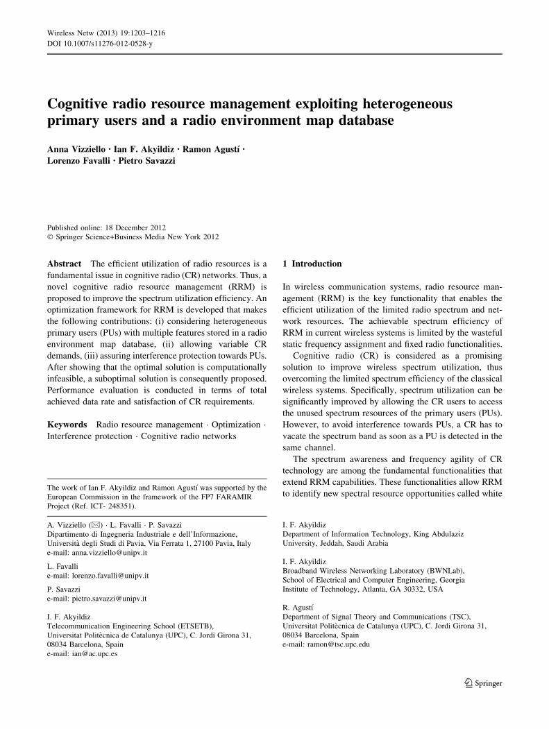
2 Proposed system architecture
As shown in Fig. 1, we consider an infrastructure-based
CR network with a centralized base station (BS) that
Fig. 1 Proposed system
architecture
1204 Wireless Netw (2013) 19:1203–1216
123
coordinates the resource allocation for CRs. According to
this scenario, CRs send sensing information to the CR BS
for processing and storing it in a REM database.
In particular, radio environment maps (REMs) have
been proposed as integrated databases that provide an
abstraction of the radio environment conditions [10, 15].
REMs are used to obtain the required geo-localized spec-
tral activities, policy information, propagation models and
other radio frequency (RF) environment information,
which are then used to estimate the available spectrum
resources. A REM covers multi-domain environmental
information such as geographical features, available ser-
vices, spectral regulations, location of diverse entities of
interest (e.g., radios, reflectors, obstacles) as well as radio
equipment capability profiles, relevant policies and past
experiences.
Specifically, the CR BS is responsible for collecting
sensing data, constructing the REM, and coordinating the
RRM. It is composed of:
• the REM Manager, which processes sensing measure-
ments to construct REMs;
• the REM storage and acquisition unit (SAU), which
stores in a local database both sensing measurements
and output data of the REM Manager,
• the REM RRM, which is responsible for the resource
management.
The measurements obtained by the CRs are collected in
the REM SAU and processed by the REM Manager to
identify the free bands and the PU types in the considered
geographical area. This process [11] is not detailed in this
paper because it is out of the scope of this work. After
classifying the existing PUs, the REM Manager updates the
stored information and for each detected PU type retrieves
the following features: bandwidth, allowable interference
level and activity pattern. The REM information is then
used by the REM RRM to calculate the available capacity
and perform resource management operations. More details
about the way of disseminating such information
throughout CR network can be found in [12].
Without loss of generality, we consider the scenario
illustrated in Fig. 1 where two types of PU networks are
considered, e.g., IEEE 802.16 and 802.11 standards. Each
PU type identifies a cluster of CRs with the associated
available capacity. As can be seen in Fig. 1, the CR clus-
ters can overlap in space. Moreover, Fig. 1 shows a third
cluster that is not associated with any PU and corresponds
to a band that is completely free from PU transmissions in
the geographical area of interest. For example, some bands
in digital video broadcasting (DVB) spectrum range are not
used at all, while other bands in the [1.240, 1.300] and
[1.525, 1.710] MHz ranges are highly under-utilized (less
than 2 %) [7]. Following this reasoning, we consider that
the information about the free bands is known and stored in
the REM. As it will be explained in Sect. 2.2, the available
capacity of the cluster associated with a free band is cal-
culated depending on the width of the free band and the
maximum CR transmission power.
To complete the scenario, since CRs may have different
demands in terms of quality of service (QoS), in Fig. 1 we
show two types of CRs that may pose different QoS
requirements to the resource allocation functionality.
Table 1 lists all the relevant notation used in this paper.
The wireless channel is frequency selective, and additive
white gaussian noise (AWGN) is considered with single-
sided power spectral density (PSD) level of N0 for all
subcarriers.
Before detailing the proposed RRM scheme, the features
of heterogeneous PUs are extracted since they directly
influence the CR parameters, as explained in Sect. 2.1. The
PU features are also used for calculating the available
capacity for each cluster, as detailed in Sect. 2.2.
2.1 PU type features extraction
To detect and classify PU signals the algorithm introduced
in [11] is exploited, as briefly recalled here below.
In particular, it is assumed that PUs employ orthogonal
frequency division multiplexing (OFDM) based standards.
A cyclostationary autocorrelation function (CAF) detects
and classifies OFDM PU signals by exploiting the period-
icities of OFDM modulations. The time interval in which
the CAF exhibits the maximum is used to distinguish dif-
ferent PUs. In fact, this time interval turns out to be equal
to 1=Dfj, where Dfj is the subcarrier spacing, and its value
is dependent on the PU type.
Spectrum availability also depends on traffic patterns.
As a consequence, a precise model of the PU activity is
useful to characterize transmission opportunities. In our
analysis, we consider the model introduced in [2], which
follows the spiky fluctuations of the PU activities over time
and models the PU traffic accurately. In this way, the
drawbacks of the usual Poisson modeling can be success-
fully overcome. A new primary user activity index /j(i) [2]
is derived to capture PU activity fluctuation.
The PU activity index /j(i) and the subcarrier spacing
Dfj are used for PU features extraction, i.e. bandwidth,
allowable interference level and idle/busy time that direct
influence CR transmitter parameters:
• The PU activity index /j(i) is useful for the definition
of PU idle/busy time. In particular, /j(i) represents the
traffic patterns on the jth band at time i. The PU arrival
rate is defined equal to the activity index /j(i). Thus,
the inter-arrival time corresponds to 1//j(i), which
is the idle time Tjidle. The busy time Tj
busy is set equal to
Wireless Netw (2013) 19:1203–1216 1205
123
1/(1 - /j(i)). As deducible, the transmission time
allowed to a CR is strongly related to the idle/busy
time of PUs.
• The subcarrier spacing Dfj is used to extract the value
of PU bandwidth and allowable interference level. In
particular, the value of Dfj obtained by the CAF
detector is compared with the known subcarriers
spacing of PU standards in order to extract its type. It
is assumed that the values of bandwidth and allowed
interference levels are known for each standard and
stored in the REM. The achievable CR data rate
directly depends on the bandwidth used by PU trans-
missions, and the PU allowed interference levels
influence the CR transmission power. In fact, besides
CR transmissions when the PU is absent, we consider
simultaneous CR and PU transmissions when a PU is
present, provided that tolerable interference level is
satisfied. Various interference limits are defined accord-
ing to the robustness of a PU standard transmission.
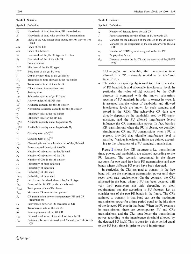
Figure 2 shows how CR parameters, i.e. transmission
time, power, and bandwidth, are adapted according to the
PU features. The scenario represented in the figure
accounts for one band free from PU transmissions and two
bands where different PU types have been detected.
In particular, the CRs assigned to transmit in the free
band will use the maximum transmission power until they
reach their rate requirements. On the contrary, the CRs
allocated in the band where a PU has been detected will
vary their parameters not only depending on their
requirements but also according to PU features. Let us
consider one of the two PU bands in the figure. The CRs
assigned to transmit in that band can use the maximum
transmission power for a time period equal to the idle time
of the detected PU type in that band. When the PU resumes
its transmission, there are contemporary PU and CRs
transmissions, and the CRs must lower the transmission
power according to the interference threshold allowed by
the detected PU itself. This is done for a time period equal
to the PU busy time in order to avoid interference.
Table 1 Notation
Symbol Definition
H0 Hypothesis of band free from PU transmissions
H1 Hypothesis of band with possible PU transmissions
jth Index of the CR cluster built around the PU type or free
band
kth Index of the CR
nth Index of subcarrier
Bj Bandwidth of the jth PU type or free band
Bk Bandwidth of the of the kth CR
i Instant of time
Tjidle Idle time of the jth PU type
Tjbusy Busy time of the jth PU type
Tj OFDM symbol time in the jth cluster
TtxjTransmission time allowed in the jth cluster
TtxkTransmission time of the kth CR
Ttxmax CR maximum transmission time
Ts Sensing time
Dfj Subcarrier spacing of jth PU type
/j(i) Activity index of jth PU type
Cjav Available capacity for the jth cluster
Cav
jNormalized available capacity for the jth cluster
cj Efficiency time in the jth cluster
ck Efficiency time for the kth CR
CðH0Þj
Available capacity under hypothesis H0
CðH1Þj
Available capacity under hypothesis H1
C1 Capacity term of CðH1Þj
C2 Capacity term of CðH1Þj
Hj,n Channel gain on the nth subcarrier of the jth band
N0 Power spectral density of AWGN
Nj Number of subcarriers in the jth band
Nk Number of subcarriers of kth CR
Kj Number of CRs in the jth cluster
Pf Probability of false detection
Pd Probability of detection
Pidle Probability of idle state
Pbusy Probability of busy state
Ijth Interference threshold allowed by jth PU type
Pk,n Power of the kth CR on the nth subcarrier
Ptotal Total power of the CRs cluster
PsmaxMaximum CR transmission power
Ps CR transmission power (contemporary PU and CR
transmissions)
PI Interference power of PU measured at CR
Rk Transmission rate of the kth CR
Rk* Rate requirement of the kth CR
Lk,i Demand level value of the ith level for kth CR
Dk,i Difference between demand level ith and (i - 1)th for kth
CR
Table 1 continued
Symbol Definition
Ik Number of demand levels for kth CR
C Factor accounting for the effects of PU towards CR
uk,j Variable for the allocation of the kth CR to the jth cluster
ck,n Variable for the assignment of the nth subcarrier to the kth
CR
nk Number of OFDM symbol assigned to the kth CR
g Propagation factor
dj,k Distance between the kth CR and the receiver of the jth PU
type
1206 Wireless Netw (2013) 19:1203–1216
123
More details about CR transmitter parameters will be
provided in the following formulation of the optimization
framework.
2.2 Available capacity calculation
At this stage, the CRs have the information about the
detected heterogeneous PUs and their features. A group of
CRs allowed to transmit in the jth band forms a cluster of
CRs. The jth band can be free or occupied by a specific PU
type. Based on the formulation in [11], we calculate the
available capacity Cjav for the jth cluster of CRs that share
it.
In more details, Cjav is defined as:
Cavj ¼ cjCj ð1Þ
where cj ¼ Ttxj= Ttxj
þ Ts
� �is the efficiency, expressed as
the ratio between the transmission time allowed in the jth
cluster Ttxjand the transmission plus sensing time Ts.
Specifically, Ts is equal to Tc ? Tr, where Tc is the time
useful to detect and classify PUs, and Tr is the time
required for consulting the REM in order to recover the
values of PU features. Cj is defined as
Cj ¼CðH0Þj Hypothesis H0
CðH1Þj Hypothesis H1
(
ð2Þ
where CðH0Þj is the capacity of the jth cluster of a free band
(hypothesis H0) and CðH1Þj is the capacity of the jth cluster
in which PU can be transmitting (hypothesis H1). Note that
the hypothesis H0 refers to a band completely free from PU
transmissions, whose information is stored in the REM;
while the hypothesis H1 refers to a band that can only be
temporally free.
Under the hypothesis H1, cj in (1) varies according to the
features of the detected PU. In particular, the available CR
transmission time available Ttxjwill depend on PU activity
index /j(i) [2]. In case of completely free band (hypothesis
H0) there is not any restriction about CR transmission time,
and Ttxjwill be equal to the time necessary to fulfill CR
requirement.
CðH0Þj is expressed as
CðH0Þj ¼ Bj
Nj
XNj
n¼1
log2 1þPsmax
Hj;n
�� ��2
N0Bj
Nj
0
@
1
A ð3Þ
in which Bj is the width of the jth band free from PU
transmissions, Nj is the number of subcarriers in the jth
band, Hj,n is the channel gain on the nth subcarrier of the
jth band and N0 is the AWGN power spectral density. Psmax
is the maximum total transmission power of CRs sharing
the available capacity of the considered cluster.
The case of temporally free band is considered in the
definition of CðH1Þj , which is computed as:
CðH1Þj ¼ C1ð1� Pf ÞPidle þ C2PdPbusy
� �ð4Þ
The first term is referred to the situation in which the PU
is absent and the CRs correctly detect the idle state without
false alarm. The second term refers to the case in which the
PU is present and the CRs correctly detect it. If the first
case happens, the CRs can transmit at the maximum power
Psmaxfor a time period Ttxj
¼ Tidlej ¼ 1=/jðiÞ. In the second
case, the CRs have to lower the transmission power to Ps
for a period Ttxj¼ T
busyj ¼ 1=ð1� /jðiÞÞ to coexist with the
PU without causing interference. More details on Ps are
given in Sect. 3.
Pidle and Pbusy are respectively the probability that a PU
is absent and the probability that a PU is present and they
depend on the PU activity model [2]. Pf is the probability
of false detection, while Pd is the probability of correct
detection of the PU detector/ classifier [11], briefly sum-
marized in Sect. 2.1.
C1 is expressed as:
C1 ¼Bj
Nj
XNj
n¼1
log2 1þPsmax
Hj;n
�� ��2
N0Bj
Nj
0
@
1
A ð5Þ
where Bj is the transmission band of the jth PU, Nj is the
number of subcarriers that can be used by the jth PU. Hj,n is
the channel gain on the nth subcarrier of the band Bj, and
N0 is the power spectral density of AWGN.
C2 refers to the case in which the PU is present and the
CRs correctly detect it; the CRs transmit and coexist with
the PU by lowering the total transmission power from Psmax
to Ps. C2 is given by
0
5
10
15
0
2
4
6
80
0.2
0.6
1
timefrequency
Pow
er
Case PU2
Case PU1
Case Free band
Fig. 2 CR parameters adaptation depending on the features of
heterogeneous PUs: transmission time, power, bandwidth
Wireless Netw (2013) 19:1203–1216 1207
123
C2 ¼Bj
Nj
XNj
n¼1
log2 1þPs Hj;n
�� ��2
PI þ N0Bj
Nj
0
@
1
A ð6Þ
Briefly, Ps is lower than Psmaxto assure interference
protection towards PUs and varies according to the PU
type. Since we have simultaneous PU and CR
transmissions, in (6) the noise is composed of AWGN
with power spectral density N0 plus the interference power
PI of PU measured at CRs.
3 Optimization framework
After deriving the available capacity for each cluster, the
achievable data rate for each CR may be computed. We
assume to use an OFDMA protocol for CR resource allo-
cation inside the cluster.
Let us consider the kth CR that belongs to the jth cluster
with available capacity Cjav. Since we are now focusing on
a single cluster, to simplify the notation in (7) we omit the
apex j in the parameters of the kth CR. The transmission
rate Rk is expressed as
Rk ¼ ckBk
Nk
PNk
n¼1 ck;n log2 1þ Pk;n Hk;nj j2CN0
BkNk
� �ð7Þ
where ck ¼ Ttxk= Ttxk
þ Tsð Þ. The transmission time Ttxkin
ck depends on the transmission time Ttxjavailable for the
CRs transmitting in the jth cluster. If the cluster is asso-
ciated with the jth detected PU type, we must take into
account the idle/busy time for computing the upper bound
of the available transmission time Ttxj, as expressed in (1),
(2) and (4); this is not required if the cluster is associated
with a free band. Besides, in the latter case the sensing time
Ts = Tc ? Tr is given only by the time Tr required for
consulting the REM. In fact, we reasonably assume that
detection time Tc is equal to zero because the information
about completely free bands is stored in the REM database.
In (7) Bk is set equal to Bj of the cluster the kth CR
belongs to. ck,n is the subcarrier assignment index indi-
cating whether the kth CR occupies the nth subcarrier or
not, in the jth cluster. Nk is the number of subcarriers
allocated to the kth CR. Pk,n is the power allocated to the
kth CR in the nth subcarrier. Hk,n is the channel gain of the
nth subcarrier for the kth CR. C is a factor that takes into
account the effects of PU towards CR depending on the
scenario. If the idle state has been correctly detected then
C ¼ 1, otherwise if the busy state has not detected or
simply there are contemporary CR and PU transmissions as
in (6), C [ 1 for the interference suffered by the CR.
In the proposed optimization framework the objective is
to minimize the difference between the sum of the avail-
able capacities,P
j=1J Cj
av, and the sum of the achievable
CR date rates in each cluster,PKj
k¼1 Rk, while assuring
interference protection towards PUs as main constraint.
The optimization problem is formulated in the following.
Objective:
minuk;j; ck;n;Pk;n; Ttxk
;R�k
XJ
j¼1
XKj
k¼1
Cavj � Rk ð8Þ
Subject to:
uk;j 2 0; 1f g 8k; j ð9Þ
ck;n 2 0; 1f g 8k; n ð10Þ
XKj
k¼1
ck;n ¼ 1 8n ð11Þ
Pk;n� 0 8k; n ð12Þ
XKj
k¼1
XN
n¼1
Pk;n�Ptotal ð13Þ
Ptotal ¼Psmax
ðH0 jH1 with PU silentÞPs ðH1 with PU transmittingÞ
ð14Þ
Ttxk¼ nkTj ð15Þ
Ttxk� Tmax
tx ð16ÞRk ¼ R�k ð17Þ
Constraints (9)–(17) are explained in the following.
Constraint (9) accounts for the allocation of the kth CR
to the jth cluster.
Constraints (10) and (11) are used to ensure that each
subcarrier cn is assigned to only one CR user k.
Constraints (12), (13) and (14) deal with power alloca-
tion. In particular, Ptotal in (13) is the total transmission
power of Kj CRs assigned to the jth cluster over all the
subcarriers Nj. As shown in (14), Ptotal must be chosen
according to the scenarios: in case of H0, the CRs can
transmit at Psmax; in case of H1, the CRs can transmit at Psmax
or at lower level Ps, as expressed in (4)–(6).
Specifically, when H1 holds, a PU has been detected and
we consider two possible situations: CR transmissions
when the PU is absent and simultaneous transmission when
the PU is present, provided that tolerable interference is
satisfied. During the idle state, the CRs transmit using their
maximum transmission power and Ptotal is set to Psmax;
during the busy state, the CRs transmit and coexist with the
PU by lowering the total transmission power Ptotal from
Psmaxto Ps to assure interference protection towards the PU.
The time period in which Ptotal is set to Psmaxor Ps is equal
to PU idle time or busy time respectively, and it is calcu-
lated according to Sect. 2.1.
The value of Ps is chosen according to the allowed
interference limit Ijth of the detected PU type, as expressed
1208 Wireless Netw (2013) 19:1203–1216
123
in (18). In particular, we consider the interference limits in
terms of received interference power allowed by PU as
defined in the standard recommendations. Ps for Kj CRs
transmitting in the jth cluster is calculated by the path-loss
propagation model:
Ps ¼ Ijth þ 10g
XKj
k¼1
lg10ðdj;kÞ ð18Þ
where g is the path loss exponent, and dj,k is the distance
between the kth CR and the receiver of the jth PU type.
Without loss of generality, we assume that dj,k can be
calculated using information stored in the REM. Consid-
ering different PU allowed interference limits, a CR adapts
more efficiently its transmission power. Briefly summa-
rizing, if CRs do not detect any PU, CRs are allowed to
transmit with their maximum power; if a PU is detected,
CRs change their transmission power depending on PU
type.
Constraints (15) and (16) are related to the transmission
time. Specifically, (15) means that CR transmission time is
equal to a certain number of OFDM symbols, whose
duration time Tj is specified for the assigned jth cluster;
while (16) fixes the upper bound on CR transmission time
Ttxkdepending on PU activity. Obviously, we do not take
into account (16) in the jth cluster that is completely free
from PU transmissions (hypothesis H0). On the contrary, in
a cluster associated with a detected PU type (hypothesis
H1), the CR transmission time is bounded by the PU idle/
busy time. Thus, when a PU is not transmitting, then
Ttxmax = Tj
idle, while when it is transmitting and there are
simultaneous PU and CR transmissions, then Ttxmax = Tj
busy,
as expressed in (1), (2) and (4).
Constraint (17) denotes that the data rate Rk of the kth
CR must satisfy its rate requirement Rk*. As it will be
explained in Sect. 4, Rk can vary by allocating subcarriers
ck,n, power level Pk,n and transmission time Ttxk, according
to (7). Moreover it should be noticed that Rk* can have one
or Ik possible values as shown in (20).
The optimization problem given in (8)–(17) is difficult
to solve, as it involves binary variables ck,n for subcarrier
assignment, continuous variables Pk,n for power allocation,
and discrete time slots Tj. The resource allocation problem
consists in assigning a CR to a cluster and then allocating
power and time slots to a subset of the subcarriers available
to meet CR demands and minimize the objective function
(8). The time interval over which these demands must be
satisfied can be interpreted as a time horizon over which
QoS requirements must be met. The discrete version of the
problem, where the time axis is divided into a number of
discrete time slots, is in general np-hard [6]. The additional
constraint in (17) further increases the difficulty in finding
the optimal solution because the feasible set is not convex.
Ideally, CR assignment to a cluster, subcarrier, power, and
time slots allocation inside the cluster should be carried out
jointly, which leads to a high computational complexity.
Following this reasoning, a reduced complexity strategy
with acceptable performance becomes necessary.
4 Proposed suboptimal solution
In this section, we describe the proposed low complexity
cognitive RRM (CRRM) scheme. Before going into details,
an overview of the solving methodology is given in the
following.
4.1 Overview on the solving CRRM methodology
The key points of the proposed solution are the opportu-
nities provided by heterogeneous PUs and the information
stored in a REM database. In particular, after the detection
and classification of different PU types, we consider their
spectral information provided by the REM to improve the
efficiency in CR resource management design. The REM
information, i.e. PU features and propagation features, is
summarized as follows:
• PU allowed interference levels Ijth,
• PU activity patterns /j(i),
• PU bandwidth Bj,
• propagation features, such as propagation factor g.
This information is valid for the geographical area
where CRs operations are applied.
Figure 3 shows the developed cognitive RRM. For
clarity, in the figure we omit the details about the CR BS
functionalities, i.e. REM Manager, REM SAU, REM
RRM, shown in Fig. 1. As a first step, sensing information
is sent by the CRs to the CR BS, which detects PU types.
The information on the detected PU types is then stored in
the REM along with their features. The CR BS uses this
information to calculate the available capacities Cjav, as
formulated in (1)–(6). Cjav is then used in the optimization
framework for CRRM.
As shown in Fig. 3, the CR BS assigns the CRs to the
appropriate cluster according to CR demands and available
capacity in the clusters, through the Admission Control
(AC) policy. Then, based on OFDMA technique, the REM
manager allocates the required resources to the admitted
CRs in each cluster, in terms of power, subcarriers, trans-
mission time, through the Cluster Resource Allocation
(CRA) protocol. This process is carried out by minimizing
the objective function expressed in (8) subject to the con-
straints (9)–(17) and (18).
The PU features stored in the REM are involved in
such optimization framework. In particular, PU allowed
Wireless Netw (2013) 19:1203–1216 1209
123
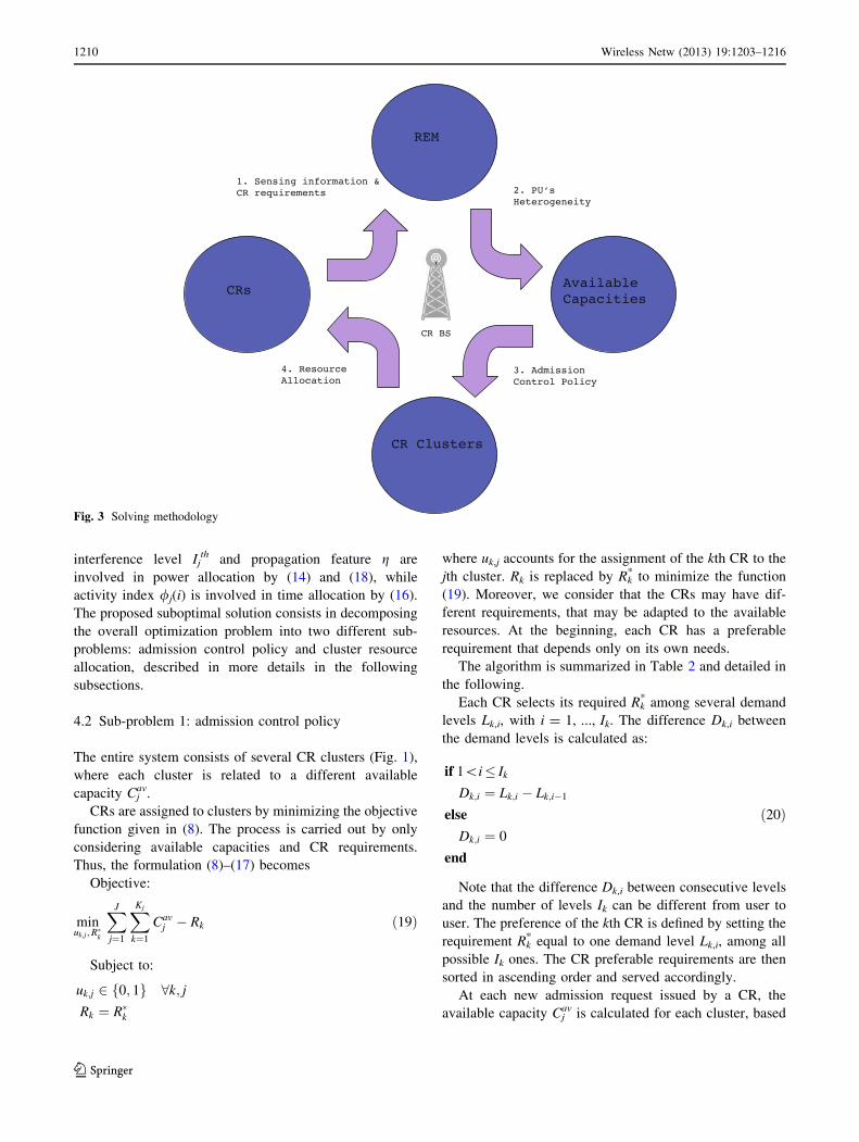
interference level Ijth and propagation feature g are
involved in power allocation by (14) and (18), while
activity index /j(i) is involved in time allocation by (16).
The proposed suboptimal solution consists in decomposing
the overall optimization problem into two different sub-
problems: admission control policy and cluster resource
allocation, described in more details in the following
subsections.
4.2 Sub-problem 1: admission control policy
The entire system consists of several CR clusters (Fig. 1),
where each cluster is related to a different available
capacity Cjav.
CRs are assigned to clusters by minimizing the objective
function given in (8). The process is carried out by only
considering available capacities and CR requirements.
Thus, the formulation (8)–(17) becomes
Objective:
minuk;j;R
�k
XJ
j¼1
XKj
k¼1
Cavj � Rk ð19Þ
Subject to:
uk;j 2 0; 1f g 8k; jRk ¼ R�k
where uk,j accounts for the assignment of the kth CR to the
jth cluster. Rk is replaced by Rk* to minimize the function
(19). Moreover, we consider that the CRs may have dif-
ferent requirements, that may be adapted to the available
resources. At the beginning, each CR has a preferable
requirement that depends only on its own needs.
The algorithm is summarized in Table 2 and detailed in
the following.
Each CR selects its required Rk* among several demand
levels Lk,i, with i = 1, ..., Ik. The difference Dk,i between
the demand levels is calculated as:
if 1\i� Ik
Dk;i ¼ Lk;i � Lk;i�1
else
Dk;i ¼ 0
end
ð20Þ
Note that the difference Dk,i between consecutive levels
and the number of levels Ik can be different from user to
user. The preference of the kth CR is defined by setting the
requirement Rk* equal to one demand level Lk,i, among all
possible Ik ones. The CR preferable requirements are then
sorted in ascending order and served accordingly.
At each new admission request issued by a CR, the
available capacity Cjav is calculated for each cluster, based
Fig. 3 Solving methodology
1210 Wireless Netw (2013) 19:1203–1216
123
on (1)–(6). Specifically, the request of the new CR is
subtracted from the available capacity of each cluster, i.e.
Cjav - Rk
* V j. The difference Cjav - Rk
* is defined as
unused capacity. If the amount is a positive value at least in
one case, the new CR is allowed to enter the system. The
CR will be assigned to the cluster corresponding to the
minimum value of the unused capacity.
If, on the other hand, Cjav - Rk
* results negative for each
cluster, a cluster mobility procedure is started: an already
served CR is chosen and moved to another cluster. In this
way the unused capacity of the source cluster increases, so
that the new CR request can be satisfied.
In case the cluster mobility procedure fails, it is neces-
sary to reduce CR requirements. Specifically, the new CR
decreases its demands Rk* to its lower level Lk,i-1 in order to
enter in the cluster with the minimum absolute value of
Cjav - Rk
*. This can be done, for instance, by moving to a
lower quality coding scheme.
If the decrease is not enough, the same procedure is
applied to another CR of the selected cluster (i. e. the one
with the minimum absolute value of Cjav - Rk). In case the
unused capacity is still negative after considering all CRs
in the selected cluster, the process is repeated by decreas-
ing on another level the requirements Lk,i-2.
The procedure is conducted level by level in order to
stay as much as possible within the preferred requests. In
case it is not possible to further reduce CR requirements in
the chosen cluster, the new request is rejected. Note that,
for simplicity, the procedure in Table 2 changes only one
level of CR requirements.
Once CR cluster assignments and final requirements are
defined, the resource allocation inside each cluster is con-
ducted as explained in the following Sect. 4.3.
4.3 Sub-problem 2: cluster resource allocation protocol
At this stage, subcarriers, powers and time slots are allo-
cated to get the data rate Rk through (7), in order to meet
the requirement Rk*. The AC policy explained above assures
that all CRs admitted to jth cluster will meet their demands.
The formulation (8)–(17) becomes
Objective:
minck;n;Pk;n; Ttxk
XJ
j¼1
XKj
k¼1
Cavj � Rk ð21Þ
Subject to:
ck;n 2 0; 1f g 8k; nXKj
k¼1
ck;n ¼ 1 8n
Pk;n� 0 8k; nXKj
k¼1
XN
n¼1
Pk;n�Ptotal
Ptotal ¼Psmax
ðH0 jH1 with PU silentÞPs ðH1 with PU transmittingÞ
Ttxk¼ nkTj
Ttxk� Tmax
tx
As stated above, a CR multiple access scheme based on
OFDMA is assumed. We refer to Kj as the total number of
CRs served in the jth cluster, and to Nj as the number of
subcarriers of one OFDM symbol for the jth cluster.
Once all parameters are initialized, the algorithm pro-
ceeds iteratively. At each iteration, the best available
subcarrier is chosen by the first CR assigned to the cluster.
Assuming at the beginning a flat transmission power
over the entire bandwidth, each subcarrier adds an equal
Table 2 Admission Control policy
1: Rk* = Lk,i V k, i (Choose CR preferable requests)
2: Rk* B Rk?1
* V k (Order CR requests)
3: uk,j = 0
4: Rk is replaced by Rk* in (19)
5: if A j s.t. Cjav - Rk
* C 0
6: uk,j = 1 with Cjav - Rk
* B Cmav - Rk
* V j = m
(i.e. assign CR k to the cluster with the minimum Cjav)
7: else if Step 5 is false
8: find l, t s.t.
Rk* B Cj
av ? Rk-l* B Cj
av ? Rk-n* &
Ctav - Rk-l
* B Csav - Rk-l
*
V n = l; V n, l = 1:k - 1, V t = s = j; V t, s, j = 1:J
(cluster mobility)
9: if step 8 is false & i = 1
10: find j s.t. Cavj � R�k
������� Cav
m � R�k�� �� V j = m
(select the cluster with minimum abs value of the unused
capacity)
11: Rk* = Lk,i-1 (decrease demand of CR k,
i.e. put Rk* to a lower level Lk,i-1 according to (20))
12: else if step 8 is false & i = 1
13: find p s.t. Rp* = Lp,i-1 & Rk
* B Cjav ? Dp,i B Cj
av ? Dw,i
V p = w; V p,w = 1:k - 1 with Dk,i = Lk,i - Lk,i-1 V k, i
(i.e. decrease demand of a CR already assigned to that cluster,
choosing the CR whose decrease minimizes the unused
capacity)
14: while k = = Kj &P
j
Pk Cj
av - Rk* [ 0
15: find p s.t. Rp* = Lp,i?1 & Cj
av - Dp,i?1 B Cjav - Dw,i?1
V p = w; V p,w = 1:Kj (i.e. increase demand of a CR,
choosing the CR whose increase minimizes the unused
capacity)
16: allocate the resources (power, bandwidth, transmission time)
to satisfy Rk* V k, following Sub-problem 2
Wireless Netw (2013) 19:1203–1216 1211
123
portion of the total power Ptotal/Nj to the CR it has been
assigned to. As explained in (14), Ptotal is equal to Psmaxor
Ps depending on the scenario. The current power Pk of the
kth CR is then allocated to its subcarriers by a water filling
policy as in [8].
At the end of each iteration, the set of available sub-
carriers S is updated by excluding the assigned ones. In
Table 3, a description of the algorithm is presented for
each OFDM symbol. The procedure continues for a num-
ber of OFDM symbols until all the available subcarriers are
assigned, satisfying the CR rate requirements.
5 Simulation results
The proposed suboptimal CRRM algorithm is evaluated in
terms of available capacity, CR achieved data rates and
satisfaction of CR requirements.
Specifically, the total data ratePKj
k¼1 Rk achieved by
CRs in each cluster is calculated. Kj is the number of CRs
served in the jth cluster, so that the unused available
capacity Cavj �
PKj
k¼1 Rk is computed. Moreover, the sat-
isfaction of CRs is calculated in terms of percentage of
non-served CRs, CRs decreasing their data rates, CRs
transmitting with their preferable requirements, and CRs
increasing their data rates.
5.1 Simulation environment
The proposed system has been implemented in MAT-
LABTM. The considered scenario includes three PU types
using OFDM transmissions, i.e. 802.11, 802.16 and DVB
signals, and a frequency band completely free from PU
transmissions.
A CR centralized network is assumed, in which CRs
send their sensing information to a CR BS, which updates
the stored REM information and broadcasts the presence of
heterogeneous PUs and their features to all CRs.
The available capacities are computed according to
(1)–(6) by using the same simulation parameters as in [11].
In particular, the interference Ijth, allowed by a PU device
receiving CR interferences, are set equal to 0.9, 9.9 and
31.5 pW respectively, which correspond to the 802.11,
802.16 and DVB PU standards. The bandwidth Bj is set
equal to 5 MHz bandwidth if a 802.16 PU signal has been
detected, 8 MHz for DVB PU signal, and 20 MHz for
802.11 PU signal. PU activity index /j(i) is randomly
distributed between 0.1 and 0.4 [2]. The wireless channel is
modeled as fading multipath with an exponential power
profile. The delay spread is equal to 0.4 ls. Without loss of
generality, the subchannel gains are known at CR receiver,
since they can be estimated using known techniques [5].
Further, we consider a system with CRs transmitting two
different kinds of video stream, with the capability of
changing the rate requirement depending on the available
resources. We use the trace statistics of actual MPEG-4
Part 2 streams in case of simple profile from [3] and H.264
streams in case of the baseline profile. For MPEG-4 Part 2
stream, the high and low quality versions are considered,
with mean bit rate equal to 400 and 90 Kbps respectively.
For H.264 stream, the high, medium and low quality ver-
sions are considered, with mean bit rate equal to 192, 128
and 64 Kbps respectively. CR preferable requirements are
randomly distributed among the mean bit rates of the two
or three quality versions of MPEG-4 Part 2 and H.264
stream, respectively.
Furthermore, three different cases are considered
depending on the amount of CR requests: Low, Medium,
and High Load.
5.2 Available capacity and CRs achieved data rates
Figure 4 shows the effects of the PU features on the
available capacity expressed by (1), whose value is nor-
malized to the bandwidth. When the REM is not used, the
time Tr to recover the PU features from the REM is equal
to zero, thus increasing the available capacity Cj. However,
without REM, it is not possible to extract the exact value of
the PU features. In this case the values are set to minimum
in order to avoid interference towards each type of PU.
Specifically, without using REM, the bandwidth is set
equal to 5 MHz, the mean value of the activity index /j is
set to 0.4 and a null value is considered for the interference
threshold Ijth allowed by the PU. In other words, the term
C2 does not contribute to Cj computation.
As shown in Fig. 4, there is a benefit in using the REM
and, as deducible, the maximum available capacity is
achieved in case of completely free band. However, among
Table 3 Sub-problem 2: Cluster Resource Allocation protocol
1: Initialization
ck,n = 0 V k, n
Rk = 0 V k
S = 1, 2, … , Nj
U = 1, 2, … , Kj
2: Subcarrier Allocation
while (S 6¼ ø or U 6¼ ø)
choose k following the ordered list of CR preferable
requirements
n ¼ argmaxn2AHk;n
ck,n = 1, S = S - n
Rk (updated with water filling policy)
if Rk = Rk* then U = U - k
end
1212 Wireless Netw (2013) 19:1203–1216
123
all types of PUs, DVB signal is the one that allows the
maximum normalized available capacity.
In the following Fig. 5 and 6, the normalized available
capacities Cav
j are calculated as Cjav /
Pj=1J Cj
av and the
same normalization is used for CR data ratesPKj
k¼1 Rk
achieved in each cluster. Figure 5 compares the normalized
available capacity and CR data rates in each cluster
obtained through CRRM algorithm. As shown in Fig. 5,
the value of the normalized available capacity Cav
j of the jth
cluster varies according to the detected PU type. In the
figure we also compare the performance of the proposed
CRRM solution, named Mobility&VRR algorithm, with a
simplified version, named VRR solution. VRR is the
acronym for taking into account variable CR rate require-
ments. The main difference between the two algorithms is
the cluster mobility procedure.
Different scenarios are considered: low traffic load
(Fig. 5a), medium load (Fig. 5b), and high load (Fig. 5c). In a
low load case, the number of CR requests is much lower than
the available resources, thus all CRs are satisfied by both VRR
and Mobility & VRR algorithms. Under this scenario, there is
not any improvement in considering the mobility of CRs
among clusters because there are enough resources to satisfy
them. On the contrary, in medium and high load scenario,
there is a benefit in carrying out the mobility. In fact, the
achieved CR data rates per each cluster is higher using
mobility and VRR than using only VRR.
Figure 5 shows that both algorithms work better in
medium and high load case than in low load scenario. In
fact, when there are few CR requests, the total available
capacity is underused and the less used cluster is just the
one with higher capacity. This drawback comes from
0
5
10
15
20
25
30
35
40
PUgeneric
PU801.11
PU801.16
PUDVB
FREEband
Cj av
[
bps/
Hz]
NO−REMREM
Fig. 4 Available capacity
0
0,1
0,2
0,3
0,4
0,5
Free band PU: DVB PU: 802.11 PU: 802.16
Bit
Rat
e norm
Available capacityAchieved Rate by Mobility & VRRAchieved Rate by VRR
(a) Low load scenario
(b) Medium load scenario
0
0,1
0,2
0,3
0,4
0,5
Cluster 1Free band
Cluster 2PU: DVB
Cluster 3PU: 802.11
Cluster 4PU: 802.16
Bit
Rat
e norm
Available capacityAchieved Rate by Mobility & VRRAchieved Rate by VRR
0
0,1
0,2
0,3
0,4
0,5
Cluster 1Free band
Cluster 2PU: DVB
Cluster 3PU: 802.11
Cluster 4PU: 802.16
Bit
Rat
e norm
Available capacityAchieved Rate by Mobility & VRRAchieved Rate by VRR
(c) High load scenario
Fig. 5 Available capacity versus achievable CR data rates
Wireless Netw (2013) 19:1203–1216 1213
123
specific characteristics of the proposed solutions. In fact,
the algorithms minimize the unused capacity at each step,
by assigning CRs to the cluster with the minimum unused
capacity. In this way we reduce the number of operations to
satisfy CR requests respect to a solution that just assigns
CRs to the cluster with the maximum available capacity.
Thus, the algorithms work well when there are several
CRs, satisfying their requests and reducing the number of
operations at the same time.
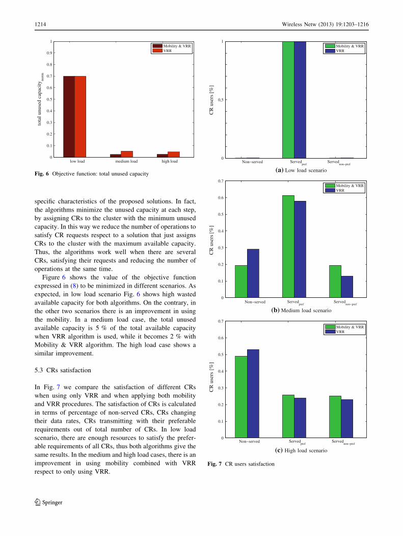
Figure 6 shows the value of the objective function
expressed in (8) to be minimized in different scenarios. As
expected, in low load scenario Fig. 6 shows high wasted
available capacity for both algorithms. On the contrary, in
the other two scenarios there is an improvement in using
the mobility. In a medium load case, the total unused
available capacity is 5 % of the total available capacity
when VRR algorithm is used, while it becomes 2 % with
Mobility & VRR algorithm. The high load case shows a
similar improvement.
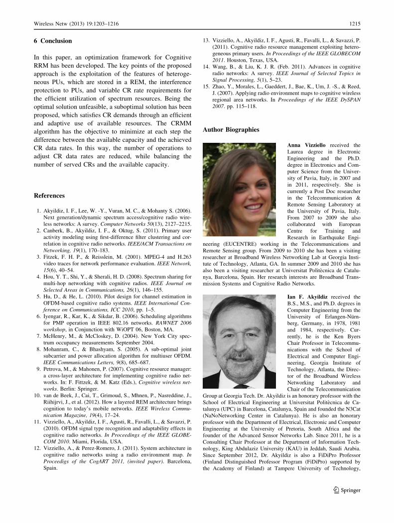
5.3 CRs satisfaction
In Fig. 7 we compare the satisfaction of different CRs
when using only VRR and when applying both mobility
and VRR procedures. The satisfaction of CRs is calculated
in terms of percentage of non-served CRs, CRs changing
their data rates, CRs transmitting with their preferable
requirements out of total number of CRs. In low load
scenario, there are enough resources to satisfy the prefer-
able requirements of all CRs, thus both algorithms give the
same results. In the medium and high load cases, there is an
improvement in using mobility combined with VRR
respect to only using VRR.
0
0.1
0.2
0.3
0.4
0.5
0.6
0.7
0.8
0.9
1to
tal u
nuse
d ca
paci
ty
n
orm
Mobility & VRRVRR
Fig. 6 Objective function: total unused capacity
0
0,5
1Mobility & VRRVRR
0
0.1
0.2
0.3
0.4
0.5
0.6
0.7Mobility & VRRVRR
0
0.1
0.2
0.3
0.4
0.5
0.6
0.7Mobility & VRRVRR
(a) Low load scenario
(b) Medium load scenario
(c) High load scenario
Fig. 7 CR users satisfaction
1214 Wireless Netw (2013) 19:1203–1216
123
6 Conclusion
In this paper, an optimization framework for Cognitive
RRM has been developed. The key points of the proposed
approach is the exploitation of the features of heteroge-
neous PUs, which are stored in a REM, the interference
protection to PUs, and variable CR rate requirements for
the efficient utilization of spectrum resources. Being the
optimal solution unfeasible, a suboptimal solution has been
proposed, which satisfies CR demands through an efficient
and adaptive use of available resources. The CRMM
algorithm has the objective to minimize at each step the
difference between the available capacity and the achieved
CR data rates. In this way, the number of operations to
adjust CR data rates are reduced, while balancing the
number of served CRs and the available capacity.
References
1. Akyildiz, I. F., Lee, W. -Y., Vuran, M. C., & Mohanty S. (2006).
Next generation/dynamic spectrum access/cognitive radio wire-
less networks: A survey. Computer Networks 50(13), 2127–2215.
2. Canberk, B., Akyildiz, I. F., & Oktug, S. (2011). Primary user
activity modeling using first-difference filter clustering and cor-
relation in cognitive radio networks. IEEE/ACM Transactions on
Networking, 19(1), 170–183.
3. Fitzek, F. H. P., & Reisslein, M. (2001). MPEG-4 and H.263
video traces for network performance evaluation. IEEE Network,
15(6), 40–54.
4. Hou, Y. T., Shi, Y., & Sherali, H. D. (2008). Spectrum sharing for
multi-hop networking with cognitive radios. IEEE Journal on
Selected Areas in Communications, 26(1), 146–155.
5. Hu, D., & He, L. (2010). Pilot design for channel estimation in
OFDM-based cognitive radio systems. IEEE International Con-
ference on Communications, ICC 2010, pp. 1–5.
6. Iyengar, R., Kar, K., & Sikdar, B. (2006). Scheduling algorithms
for PMP operation in IEEE 802.16 networks. RAWNET 2006
workshop, in Conjunction with WiOPT 06, Boston, MA.
7. McHenry, M., & McCloskey, D. (2004). New York City spec-
trum occupancy measurements September 2004.
8. Mohanram, C., & Bhashyam, S. (2005). A sub-optimal joint
subcarrier and power allocation algorithm for multiuser OFDM.
IEEE Communications Letters, 9(8), 685–687.
9. Petrova, M., & Mahonen, P. (2007). Cognitive resource manager:
a cross-layer architecture for implementing cognitive radio net-
works. In: F. Fittzek, & M. Katz (Eds.), Cognitive wireless net-
works. Berlin: Springer.
10. van de Beek, J., Cai, T., Grimoud, S., Mhnen, P., Nasreddine, J.,
Riihijrvi, J., et al. (2012). How a layered REM architecture brings
cognition to today’s mobile networks. IEEE Wireless Commu-
nication Magazine, 19(4), 17–24.
11. Vizziello, A., Akyildiz, I. F., Agusti, R., Favalli, L., & Savazzi, P.
(2010). OFDM signal type recognition and adaptability effects in
cognitive radio networks. In Proceedings of the IEEE GLOBE-
COM 2010. Miami, Florida, USA.
12. Vizziello, A., & Perez-Romero, J. (2011). System architecture in
cognitive radio networks using a radio environment map. In
Proceedigs of the CogART 2011, (invited paper). Barcelona,
Spain.
13. Vizziello, A., Akyildiz, I. F., Agusti, R., Favalli, L., & Savazzi, P.
(2011). Cognitive radio resource management exploiting hetero-
geneous primary users. In Proceedings of the IEEE GLOBECOM
2011. Houston, Texas, USA.
14. Wang, B., & Liu, K. J. R. (Feb. 2011). Advances in cognitive
radio networks: A survey. IEEE Journal of Selected Topics in
Signal Processing, 5(1), 5–23.
15. Zhao, Y., Morales, L., Gaeddert, J., Bae, K., Um, J. -S., & Reed,
J. (2007). Applying radio environment maps to cognitive wireless
regional area networks. In Proceedings of the IEEE DySPAN
2007. pp. 115–118.
Author Biographies
Anna Vizziello received the
Laurea degree in Electronic
Engineering and the Ph.D.
degree in Electronics and Com-
puter Science from the Univer-
sity of Pavia, Italy, in 2007 and
in 2011, respectively. She is
currently a Post Doc researcher
in the Telecommunication &
Remote Sensing Laboratory at
the University of Pavia, Italy.
From 2007 to 2009 she also
collaborated with European
Centre for Training and
Research in Earthquake Engi-
neering (EUCENTRE) working in the Telecommunications and
Remote Sensing group. From 2009 to 2010 she has been a visiting
researcher at Broadband Wireless Networking Lab at Georgia Insti-
tute of Technology, Atlanta, GA. In summer 2009 and 2010 she has
also been a visiting researcher at Universitat Politecnica de Catalu-
nya, Barcelona, Spain. Her research interests are Broadband Trans-
mission Systems and Cognitive Radio Networks.
Ian F. Akyildiz received the
B.S., M.S., and Ph.D. degrees in
Computer Engineering from the
University of Erlangen-Nurn-
berg, Germany, in 1978, 1981
and 1984, respectively. Cur-
rently, he is the Ken Byers
Chair Professor in Telecommu-
nications with the School of
Electrical and Computer Engi-
neering, Georgia Institute of
Technology, Atlanta, the Direc-
tor of the Broadband Wireless
Networking Laboratory and
Chair of the Telecommunication
Group at Georgia Tech. Dr. Akyildiz is an honorary professor with the
School of Electrical Engineering at Universitat Politecnica de Ca-
talunya (UPC) in Barcelona, Catalunya, Spain and founded the N3Cat
(NaNoNetworking Center in Catalunya). He is also an honorary
professor with the Department of Electrical, Electronic and Computer
Engineering at the University of Pretoria, South Africa and the
founder of the Advanced Sensor Networks Lab. Since 2011, he is a
Consulting Chair Professor at the Department of Information Tech-
nology, King Abdulaziz University (KAU) in Jeddah, Saudi Arabia.
Since September 2012, Dr. Akyildiz is also a FiDiPro Professor
(Finland Distinguished Professor Program (FiDiPro) supported by
the Academy of Finland) at Tampere University of Technology,
Wireless Netw (2013) 19:1203–1216 1215
123
Department of Communications Engineering, Finland. He is the
Editor-in-Chief of Computer Networks (Elsevier) Journal, and the
founding Editor-in-Chief of the Ad Hoc Networks (Elsevier) Journal,
the Physical Communication (Elsevier) Journal and the Nano Com-
munication Networks (Elsevier) Journal. He is an IEEE Fellow (1996)
and an ACM Fellow (1997). He received numerous awards from
IEEE and ACM. His current research interests are in nanonetworks,
Long Term Evolution (LTE) advanced networks, cognitive radio
networks and wireless sensor networks.
Ramon Agustı received the
Engineer of Telecommunica-
tions degree from the Universi-
dad Politecnica de Madrid,
Spain, in 1973, and the Ph.D.
degree from the Universitat Po-
litecnica de Catalunya (UPC),
Spain, 1978. He became Full
Professor of the Department of
Signal Theory and Communi-
cations (UPC) in 1987. After
graduation he was working in
the field of digital communica-
tions with particular emphasis
on transmission and develop-
ment aspects in fixed digital radio, both radio relay and mobile
communications. For the last twenty years he has been mainly con-
cerned with aspects related to radio resource management in mobile
communications. He has published about two hundred papers in these
areas and co-authored three books. He participated in the European
program COST 231 and in the COST 259 as Spanish representative
delegate. He has also participated in the RACE, ACTS and IST
European research programs as well as in many private and public
funded projects. He received the Catalonia Engineer of the year prize
in 1998 and the Narcis Monturiol Medal issued by the Government of
Catalonia in 2002 for his research contributions to the mobile com-
munications field. He is a Member of the Spanish Engineering
Academy.
Favalli Lorenzo graduated in
Electronic Engineering form
Politechnic of Milano in1987
and obtained the Ph.D. from the
same university in 1991. Since
1991 he is with the University
of Pavia first as Assistant Pro-
fessor and, from 2000 as Asso-
ciate Professor. During his
career Dr. Favalli has been
recipient of several prizes, such
as the grant from SIP (now
Telecom Italia) for his gradua-
tion thesis titled ‘‘Telephone
service on the C-NET local area
network’’. The same work won the 1987 ‘‘Oglietti’’ prize from
AEI-CSELT as the best thesis work on communication and switching.
In 1989 obtained a AEI-ISS grant and spent about one year as a
visiting scientist at the Computer Communications Research Center
of the Washington University in St. Louis (USA). In 1988 he also won
the special prize at the international contest ‘‘Computer in the
Cathedral’’ sponsored by NCR and International Cathedral Associa-
tion developing a multimedia hypertext system for the fruition of
cultural heritage. He is a member of the commission for Distance
Learning activities of the Faculty of Engineering and has served as the
head of the Scientific Board of the Engineering Library and he is still
a member of the board. He has participated in many research projects
funded by public institutions (MIUR- PRIN and FIRB projects) and
private companies (STmicroelectronics, Ericsson, Alenia, Marconi).
His research activity has covered various aspects of signal analysis, in
particular video, and transmission in both wireless and wired
networks.
Pietro Savazzi received the
Laurea degree in Electronics
Engineering from the University
of Pavia in 1995. In 1999 he
obtained the Ph.D. in Electron-
ics and Computer Science from
the same University and then he
joined Ericsson Lab Italy, in
Milan, as a system designer,
working on broadband micro-
wave systems. In 2001 he
moved to Marconi Mobile,
Genoa, Italy, as a system
designer in the filed of 3G
wireless systems. Since 2003 he
has been working at the University of Pavia where he is currently
teaching, as an assistant professor, two courses on signal processing
and digital communications. His main research interests are in
wireless systems.
1216 Wireless Netw (2013) 19:1203–1216
123