Embed Size (px)
Citation preview
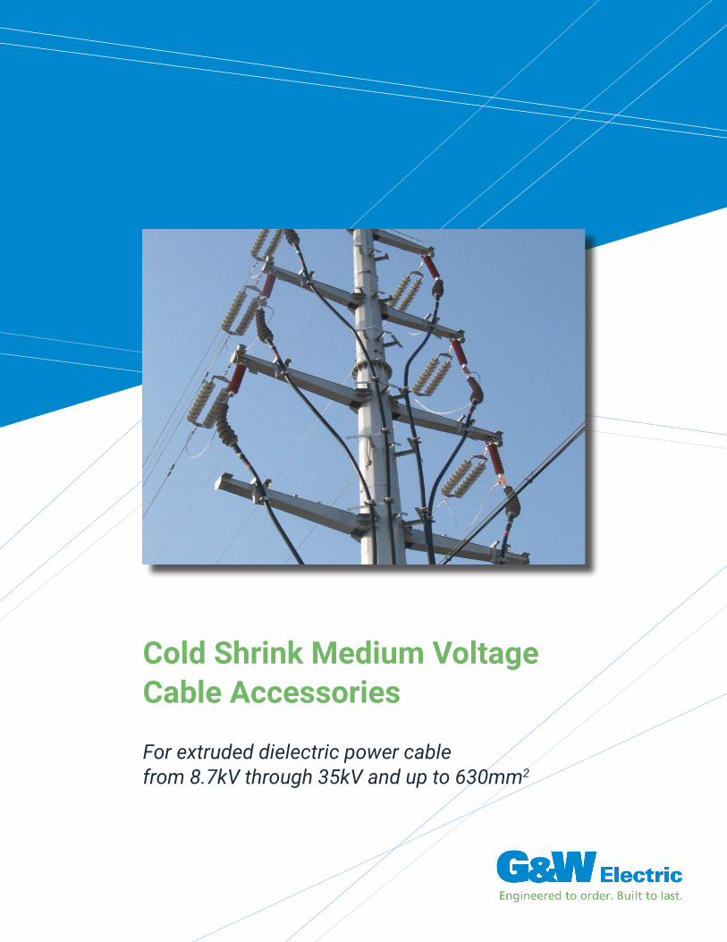
Cold Shrink Medium Voltage Cable Accessories
For extruded dielectric power cable from 8.7kV through 35kV and up to 630mm2
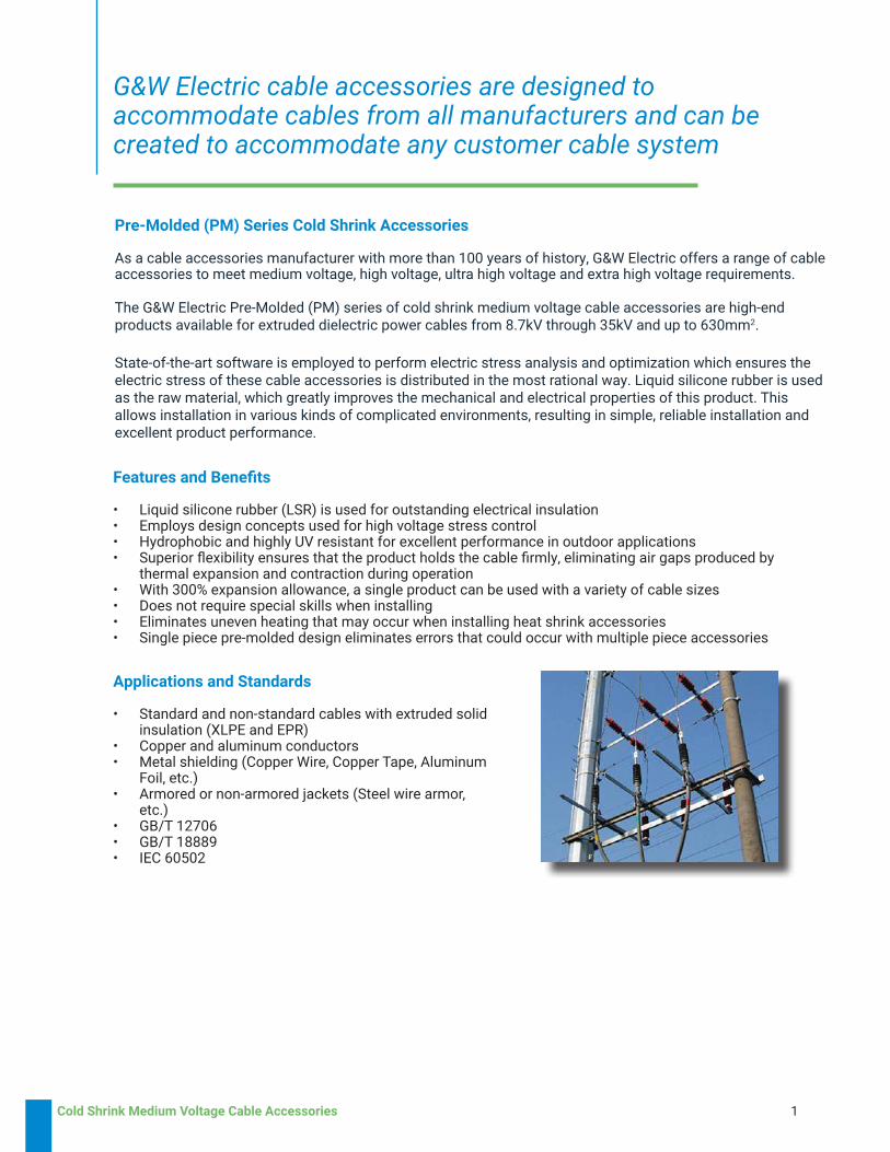
Applications and Standards
• Standard and non-standard cables with extruded solid insulation (XLPE and EPR)
• Copper and aluminum conductors• Metal shielding (Copper Wire, Copper Tape, Aluminum
Foil, etc.)• Armored or non-armored jackets (Steel wire armor,
etc.)• GB/T 12706• GB/T 18889• IEC 60502
Cold Shrink Medium Voltage Cable Accessories 1
G&W Electric cable accessories are designed to accommodate cables from all manufacturers and can be created to accommodate any customer cable system
State-of-the-art software is employed to perform electric stress analysis and optimization which ensures the electric stress of these cable accessories is distributed in the most rational way. Liquid silicone rubber is used as the raw material, which greatly improves the mechanical and electrical properties of this product. This allows installation in various kinds of complicated environments, resulting in simple, reliable installation and excellent product performance.
Features and Benefits
• Liquid silicone rubber (LSR) is used for outstanding electrical insulation• Employs design concepts used for high voltage stress control• Hydrophobic and highly UV resistant for excellent performance in outdoor applications• Superior flexibility ensures that the product holds the cable firmly, eliminating air gaps produced by
thermal expansion and contraction during operation • With 300% expansion allowance, a single product can be used with a variety of cable sizes• Does not require special skills when installing • Eliminates uneven heating that may occur when installing heat shrink accessories• Single piece pre-molded design eliminates errors that could occur with multiple piece accessories
As a cable accessories manufacturer with more than 100 years of history, G&W Electric offers a range of cable accessories to meet medium voltage, high voltage, ultra high voltage and extra high voltage requirements.
The G&W Electric Pre-Molded (PM) series of cold shrink medium voltage cable accessories are high-end products available for extruded dielectric power cables from 8.7kV through 35kV and up to 630mm2.
Pre-Molded (PM) Series Cold Shrink Accessories
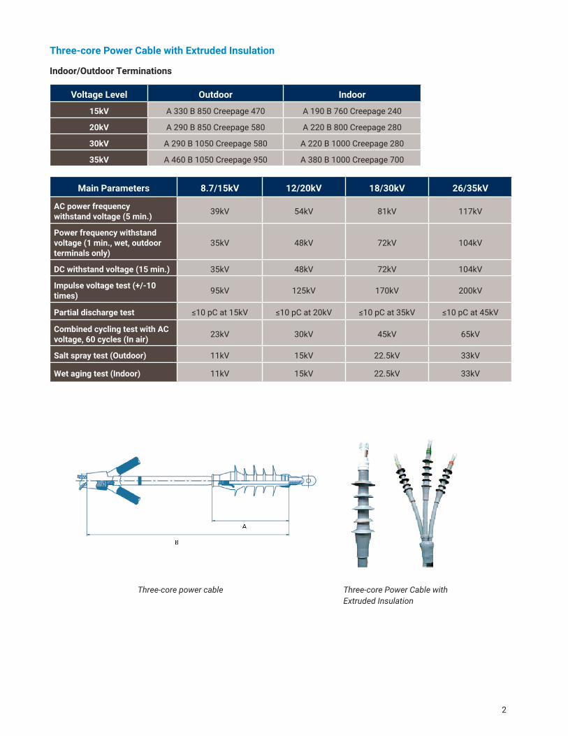
Three-core Power Cable with Extruded Insulation
Voltage Level Outdoor Indoor
15kV A 330 B 850 Creepage 470 A 190 B 760 Creepage 240
20kV A 290 B 850 Creepage 580 A 220 B 800 Creepage 280
30kV A 290 B 1050 Creepage 580 A 220 B 1000 Creepage 280
35kV A 460 B 1050 Creepage 950 A 380 B 1000 Creepage 700
Main Parameters 8.7/15kV 12/20kV 18/30kV 26/35kV
AC power frequency withstand voltage (5 min.) 39kV 54kV 81kV 117kV
Power frequency withstand voltage (1 min., wet, outdoor terminals only)
35kV 48kV 72kV 104kV
DC withstand voltage (15 min.) 35kV 48kV 72kV 104kV
Impulse voltage test (+/-10 times) 95kV 125kV 170kV 200kV
Partial discharge test ≤10 pC at 15kV ≤10 pC at 20kV ≤10 pC at 35kV ≤10 pC at 45kV
Combined cycling test with AC voltage, 60 cycles (In air) 23kV 30kV 45kV 65kV
Salt spray test (Outdoor) 11kV 15kV 22.5kV 33kV
Wet aging test (Indoor) 11kV 15kV 22.5kV 33kV
Three-core power cable Three-core Power Cable with Extruded Insulation
2
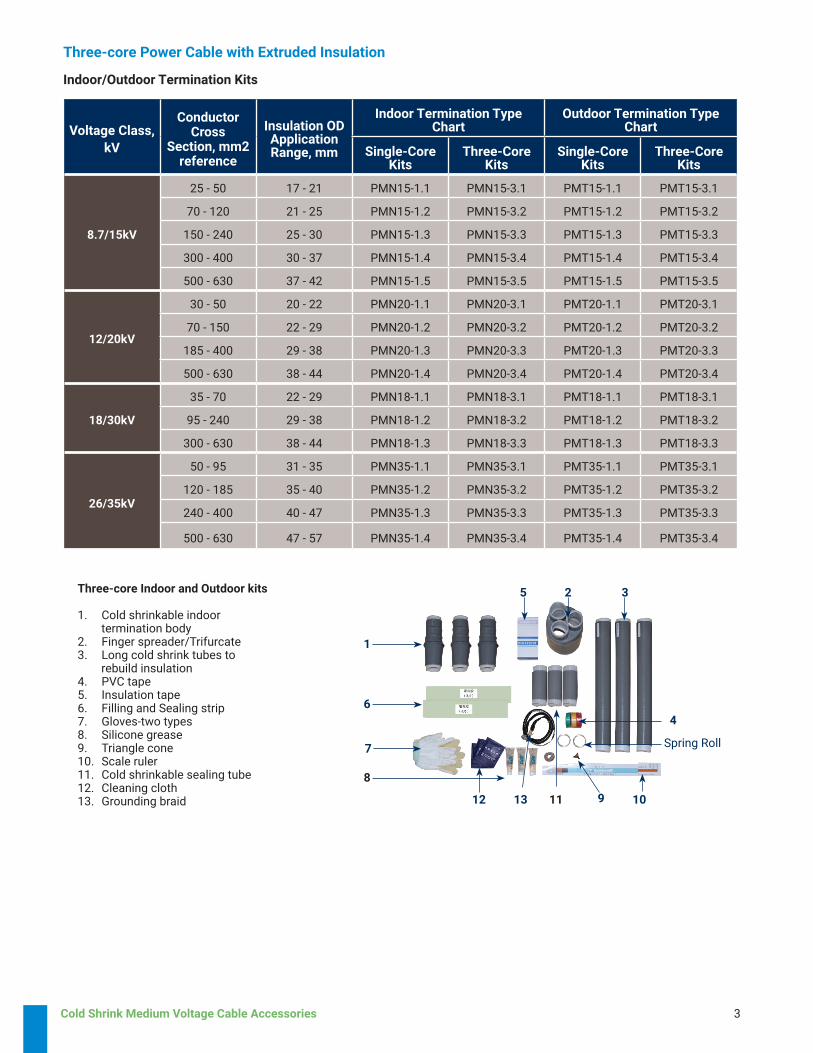
Indoor/Outdoor Terminations
Cold Shrink Medium Voltage Cable Accessories 3
Three-core Power Cable with Extruded Insulation
Voltage Class, kV
ConductorCross
Section, mm2reference
Insulation OD Application Range, mm
Indoor Termination Type Chart
Outdoor Termination Type Chart
Single-CoreKits
Three-CoreKits
Single-CoreKits
Three-CoreKits
8.7/15kV
25 - 50 17 - 21 PMN15-1.1 PMN15-3.1 PMT15-1.1 PMT15-3.1
70 - 120 21 - 25 PMN15-1.2 PMN15-3.2 PMT15-1.2 PMT15-3.2
150 - 240 25 - 30 PMN15-1.3 PMN15-3.3 PMT15-1.3 PMT15-3.3
300 - 400 30 - 37 PMN15-1.4 PMN15-3.4 PMT15-1.4 PMT15-3.4
500 - 630 37 - 42 PMN15-1.5 PMN15-3.5 PMT15-1.5 PMT15-3.5
12/20kV
30 - 50 20 - 22 PMN20-1.1 PMN20-3.1 PMT20-1.1 PMT20-3.1
70 - 150 22 - 29 PMN20-1.2 PMN20-3.2 PMT20-1.2 PMT20-3.2
185 - 400 29 - 38 PMN20-1.3 PMN20-3.3 PMT20-1.3 PMT20-3.3
500 - 630 38 - 44 PMN20-1.4 PMN20-3.4 PMT20-1.4 PMT20-3.4
18/30kV
35 - 70 22 - 29 PMN18-1.1 PMN18-3.1 PMT18-1.1 PMT18-3.1
95 - 240 29 - 38 PMN18-1.2 PMN18-3.2 PMT18-1.2 PMT18-3.2
300 - 630 38 - 44 PMN18-1.3 PMN18-3.3 PMT18-1.3 PMT18-3.3
26/35kV
50 - 95 31 - 35 PMN35-1.1 PMN35-3.1 PMT35-1.1 PMT35-3.1
120 - 185 35 - 40 PMN35-1.2 PMN35-3.2 PMT35-1.2 PMT35-3.2
240 - 400 40 - 47 PMN35-1.3 PMN35-3.3 PMT35-1.3 PMT35-3.3
500 - 630 47 - 57 PMN35-1.4 PMN35-3.4 PMT35-1.4 PMT35-3.4
Three-core Indoor and Outdoor kits
1. Cold shrinkable indoor termination body2. Finger spreader/Trifurcate3. Long cold shrink tubes to rebuild insulation4. PVC tape5. Insulation tape6. Filling and Sealing strip7. Gloves-two types8. Silicone grease9. Triangle cone10. Scale ruler11. Cold shrinkable sealing tube12. Cleaning cloth13. Grounding braid
Indoor/Outdoor Termination Kits
1
5
8
7
6
32
Spring Roll
4
13 11 9 1012
Three-core Power Cable with Extruded Insulation
Voltage Class, kV
ConductorCross Section, mm2,
reference
Insulation OD Application Range, mm
Straight Though Joint Type Chart
Single-CoreKits
Three-CoreKits
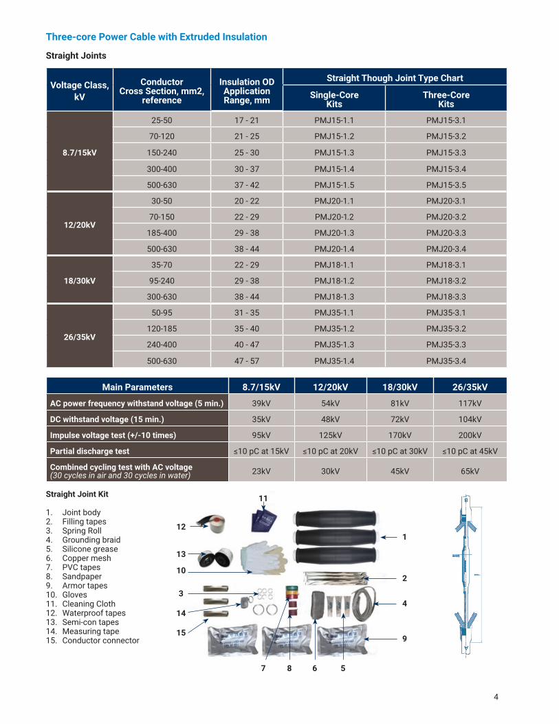
8.7/15kV
25-50 17 - 21 PMJ15-1.1 PMJ15-3.1
70-120 21 - 25 PMJ15-1.2 PMJ15-3.2
150-240 25 - 30 PMJ15-1.3 PMJ15-3.3
300-400 30 - 37 PMJ15-1.4 PMJ15-3.4
500-630 37 - 42 PMJ15-1.5 PMJ15-3.5
12/20kV
30-50 20 - 22 PMJ20-1.1 PMJ20-3.1
70-150 22 - 29 PMJ20-1.2 PMJ20-3.2
185-400 29 - 38 PMJ20-1.3 PMJ20-3.3
500-630 38 - 44 PMJ20-1.4 PMJ20-3.4
18/30kV
35-70 22 - 29 PMJ18-1.1 PMJ18-3.1
95-240 29 - 38 PMJ18-1.2 PMJ18-3.2
300-630 38 - 44 PMJ18-1.3 PMJ18-3.3
26/35kV
50-95 31 - 35 PMJ35-1.1 PMJ35-3.1
120-185 35 - 40 PMJ35-1.2 PMJ35-3.2
240-400 40 - 47 PMJ35-1.3 PMJ35-3.3
500-630 47 - 57 PMJ35-1.4 PMJ35-3.4
Main Parameters 8.7/15kV 12/20kV 18/30kV 26/35kV
AC power frequency withstand voltage (5 min.) 39kV 54kV 81kV 117kV
DC withstand voltage (15 min.) 35kV 48kV 72kV 104kV
Impulse voltage test (+/-10 times) 95kV 125kV 170kV 200kV
Partial discharge test ≤10 pC at 15kV ≤10 pC at 20kV ≤10 pC at 30kV ≤10 pC at 45kV
Combined cycling test with AC voltage (30 cycles in air and 30 cycles in water) 23kV 30kV 45kV 65kV
4
Straight Joints
Straight Joint Kit
1. Joint body2. Filling tapes3. Spring Roll 4. Grounding braid5. Silicone grease6. Copper mesh7. PVC tapes8. Sandpaper9. Armor tapes10. Gloves11. Cleaning Cloth12. Waterproof tapes13. Semi-con tapes14. Measuring tape15. Conductor connector
587
9
4
2
1
15
14
3
10
13
6
11
12
Three-core Power Cable with Extruded Insulation
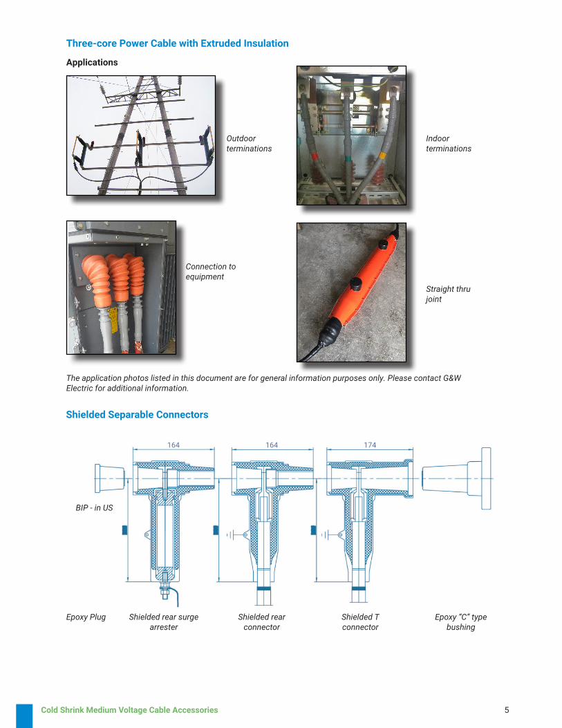
Applications
Shielded Separable Connectors
Epoxy Plug Shielded rear surge arrester
Shielded rear connector
Shielded T connector
Epoxy “C” type bushing
Outdoorterminations
Indoorterminations
Connection to equipment
Straight thru joint
The application photos listed in this document are for general information purposes only. Please contact G&W Electric for additional information.
Cold Shrink Medium Voltage Cable Accessories 5
BIP - in US
164 164 174
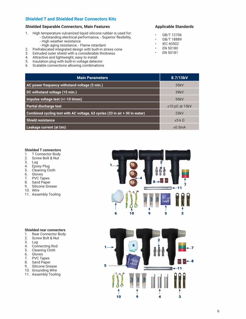
Main Parameters 8.7/15kV
AC power frequency withstand voltage (5 min.) 35kV
DC withstand voltage (15 min.) 39kV
Impulse voltage test (+/-10 times) 95kV
Partial discharge test ≤10 pC at 15kV
Combined cycling test with AC voltage, 63 cycles (33 in air + 30 in water) 23kV
Shield resistance ≤5 k Ω
Leakage current (at Um) ≤0.5mA
Shielded T connectors 1. T Connector Body2. Screw Bolt & Nut3. Lug4. Epoxy Plug5. Cleaning Cloth6. Gloves7. PVC Tapes8. Sand Paper9. Silicone Grease10. WIre11. Assembly Tooling
Shielded rear connectors1. Rear Connector Body2. Screw Bolt & Nut3. Lug4. Connecting Rod5. Cleaning Cloth6. Gloves7. PVC Tapes8. Sand Paper9. Silicone Grease10. Grounding WIre11. Assembly Tooling
Shielded Separable Connectors, Main Features1. High temperature vulcanized liquid silicone rubber is used for: - Outstanding electrical performance, - Superior flexibility, - High weather resistance - High aging resistance, - Flame retardant2. Prefrabicated integrated design with built-in stress cone3. Extruded outer shield with a considerable thickness4. Attractive and lightweight, easy to install5. Insulation plug with built-in voltage detector6. Scalable connections allowing combinations
• GB/T 12706• GB/T 18889• IEC 60502• EN 50180• EN 50181
Applicable Standards
Shielded T and Shielded Rear Connectors Kits
6
12
34
5
910
7
8
6
11
1 2
3596
48
711
10
Cold Shrink Medium Voltage Cable Accessories 7
Voltage Class, kV
ConductorCross
Section, mm2, reference
Cable Insulation
range (mm)
Shielded T ConnectorType Chart
Shielded Rear ConnectorType Chart
Single-core Models
Three-Ccre Models
Single-core Models
Three-Ccre Models
8.7/15kV
25-50 17 - 21 PMTC15-1.1 PMTC15-3.1 PMBC15-1.1 PMBC15-3.1
70-120 21 - 25 PMTC15-1.2 PMTC15-3.2 PMBC15-1.2 PMBC15-3.2
150-240 25 - 30 PMTC15-1.3 PMTC15-3.3 PMBC15-1.3 PMBC15-3.3
300-400 30 - 37 PMTC15-1.4 PMTC15-3.4 PMBC15-1.4 PMBC15-3.4
500-630 37 - 42 PMTC15-1.5 PMTC15-3.5 PMBC15-1.5 PMBC15-3.5
Name Units Parameters
Product Model - PMBA15 (17/45)
System nominal voltage kV 10
Surge protector rated voltage kV 17
Continuous operating voltage kV 13.6
Nominal discharge current, In kA 5
Reference voltage, DC, 1 mA kV ≥24
Leakage current, 0.75U, 1 mA μ A ≤10
Steep current impulse residual voltage kV ≤51.8
Lightning impulse residual voltage kV ≤45
Switching impulse residual voltage kV ≤35
Resistive current (Peak value) μ A ≤200
Full current (Peak value) μ A ≤700
Partial discharge at 14.3 kV pC ≤10
2ms square wave current impulse withstand A 200
High current impulse withstand kA 65
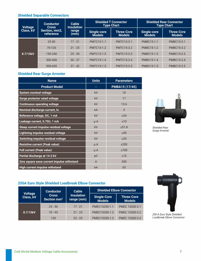
Shielded Rear Surge Arrester
Shielded Separable Connectors
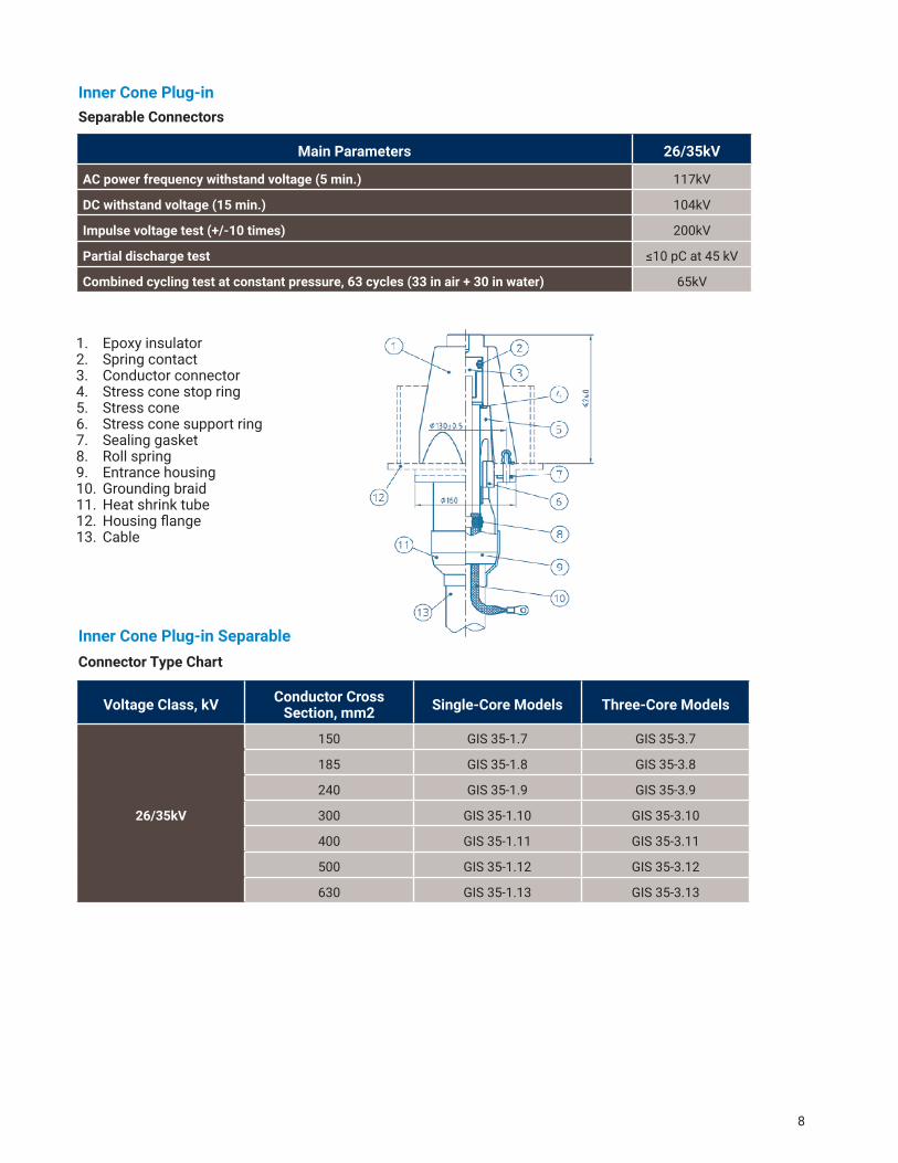
250A Euro Style Shielded Loadbreak Elbow Connector
Voltage Class, kV
Conductor Cross
Section mm2
Cable Insulation
range (mm)
Shielded Elbow Connector
Single-Core Models
Three-Core Models
8.7/15kV
25 - 50 17 - 21 PMEC15250-1.1 PMEC 15200-3.1
70 - 95 21 - 23 PMEC15250-1.2 PMEC 15200-3.2
120 23 - 25 PMEC15250-1.3 PMEC 15200-3.3
Shielded RearSurge Arrester
250 A Euro Style Shielded Loadbreak Elbow Connector
8
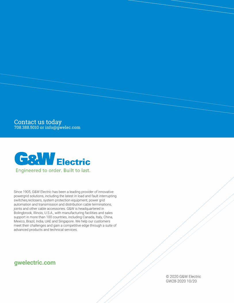
Inner Cone Plug-inSeparable Connectors
1. Epoxy insulator2. Spring contact3. Conductor connector4. Stress cone stop ring5. Stress cone6. Stress cone support ring7. Sealing gasket8. Roll spring9. Entrance housing10. Grounding braid11. Heat shrink tube12. Housing flange13. Cable
Main Parameters 26/35kV
AC power frequency withstand voltage (5 min.) 117kV
DC withstand voltage (15 min.) 104kV
Impulse voltage test (+/-10 times) 200kV
Partial discharge test ≤10 pC at 45 kV
Combined cycling test at constant pressure, 63 cycles (33 in air + 30 in water) 65kV
Inner Cone Plug-in Separable
Voltage Class, kV Conductor CrossSection, mm2 Single-Core Models Three-Core Models
26/35kV
150 GIS 35-1.7 GIS 35-3.7
185 GIS 35-1.8 GIS 35-3.8
240 GIS 35-1.9 GIS 35-3.9
300 GIS 35-1.10 GIS 35-3.10
400 GIS 35-1.11 GIS 35-3.11
500 GIS 35-1.12 GIS 35-3.12
630 GIS 35-1.13 GIS 35-3.13
Connector Type Chart
Contact us today708.388.5010 or [email protected]
Since 1905, G&W Electric has been a leading provider of innovative powergrid solutions, including the latest in load and fault interrupting switches,reclosers, system protection equipment, power grid automation and transmission and distribution cable terminations, joints and other cable accessories. G&W is headquartered in Bolingbrook, Illinois, U.S.A., with manufacturing facilities and sales support in more than 100 countries, including Canada, Italy, China, Mexico, Brazil, India, UAE and Singapore. We help our customers meet their challenges and gain a competitive edge through a suite of advanced products and technical services.
© 2020 G&W Electric GW28-2020 10/20
gwelectric.com