Embed Size (px)
DESCRIPTION
core mould
Citation preview
U.S. 800-626-6653 � Canada 800-387-6600 � www.dme.net
DESIGN & ASSEMBLY GUIDE
Collapsible Core & Collapsible Minicore

DME
DESIGN & ASSEMBLY GUIDE
U.S. 800-626-6653 � Canada 800-387-6600 � www.dme.net
Collapsible Core and Collapsible MinicoreThis data is designed to assist you in using the Collapsible Core and Collapsible Minicore. Included are core, minicore and mold base machining
dimensions and data. Provided as well are design checklists, mold starting procedures, and core, minicore and center pin grinding instructions.
Drawings are also included for an early ejector return for reference when one is required.
Should you require further assistance, contact your Customer Service Representative (see phone numbers below) who will put you in touch with
the Applications Engineering Department or your local Field Representative.
DME
DESIGN & ASSEMBLY GUIDE
U.S. 800-626-6653 � Canada 800-387-6600 � www.dme.net
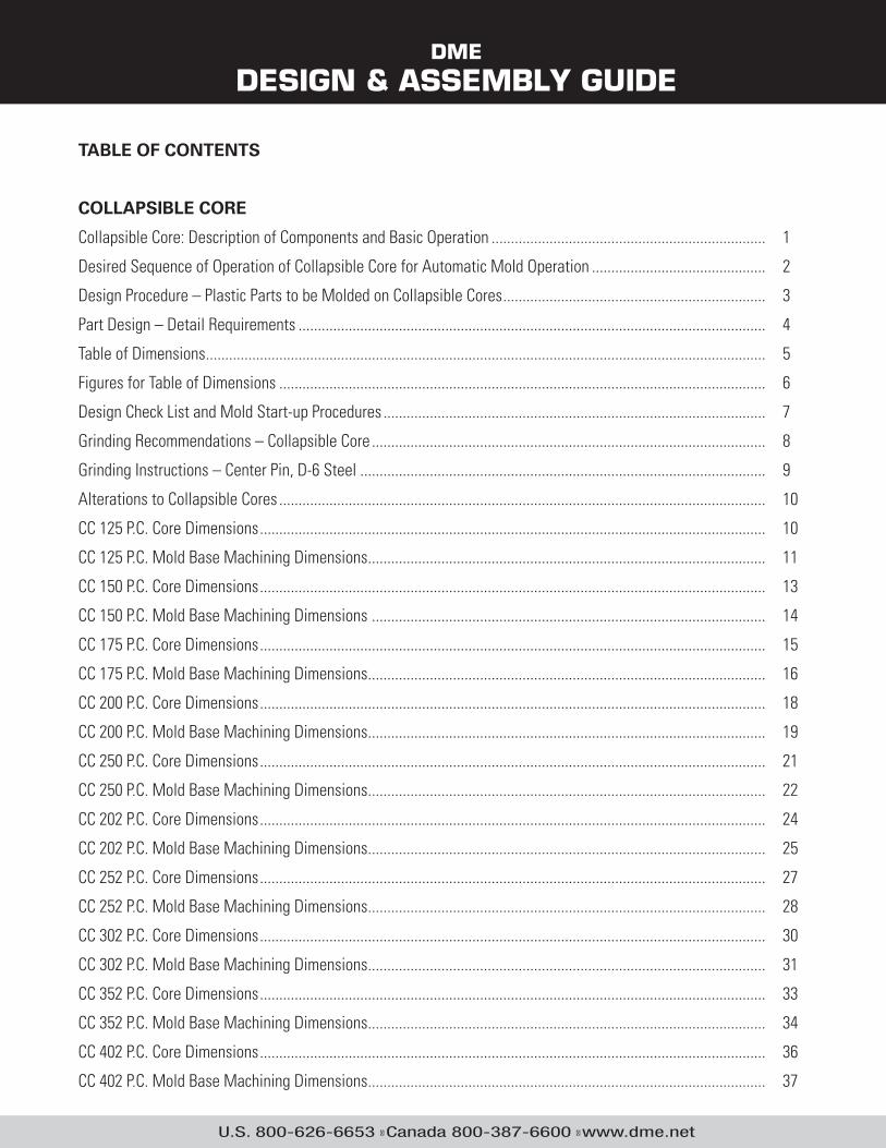
TABLE OF CONTENTS
COLLAPSIBLE CORE
Collapsible Core: Description of Components and Basic Operation ....................................................................... 1
Desired Sequence of Operation of Collapsible Core for Automatic Mold Operation ............................................. 2
Design Procedure – Plastic Parts to be Molded on Collapsible Cores .................................................................... 3
Part Design – Detail Requirements ......................................................................................................................... 4
Table of Dimensions ................................................................................................................................................. 5
Figures for Table of Dimensions .............................................................................................................................. 6
Design Check List and Mold Start-up Procedures ................................................................................................... 7
Grinding Recommendations – Collapsible Core ...................................................................................................... 8
Grinding Instructions – Center Pin, D-6 Steel ......................................................................................................... 9
Alterations to Collapsible Cores .............................................................................................................................. 10
CC 125 P.C. Core Dimensions ................................................................................................................................... 10
CC 125 P.C. Mold Base Machining Dimensions ....................................................................................................... 11
CC 150 P.C. Core Dimensions ................................................................................................................................... 13
CC 150 P.C. Mold Base Machining Dimensions ...................................................................................................... 14
CC 175 P.C. Core Dimensions ................................................................................................................................... 15
CC 175 P.C. Mold Base Machining Dimensions ....................................................................................................... 16
CC 200 P.C. Core Dimensions ................................................................................................................................... 18
CC 200 P.C. Mold Base Machining Dimensions ....................................................................................................... 19
CC 250 P.C. Core Dimensions ................................................................................................................................... 21
CC 250 P.C. Mold Base Machining Dimensions ....................................................................................................... 22
CC 202 P.C. Core Dimensions ................................................................................................................................... 24
CC 202 P.C. Mold Base Machining Dimensions ....................................................................................................... 25
CC 252 P.C. Core Dimensions ................................................................................................................................... 27
CC 252 P.C. Mold Base Machining Dimensions ....................................................................................................... 28
CC 302 P.C. Core Dimensions ................................................................................................................................... 30
CC 302 P.C. Mold Base Machining Dimensions ....................................................................................................... 31
CC 352 P.C. Core Dimensions ................................................................................................................................... 33
CC 352 P.C. Mold Base Machining Dimensions ....................................................................................................... 34
CC 402 P.C. Core Dimensions ................................................................................................................................... 36
CC 402 P.C. Mold Base Machining Dimensions ....................................................................................................... 37
DME
DESIGN & ASSEMBLY GUIDE
U.S. 800-626-6653 � Canada 800-387-6600 � www.dme.net
CC 502 P.C. Core Dimensions ................................................................................................................................... 39
CC 502 P.C. Mold Base Machining Dimensions ....................................................................................................... 40
CC 602 P.C. Core Dimensions ................................................................................................................................... 42
CC 602 PC Mold Base Machining Dimensions ........................................................................................................ 43
CC 652 P.C. Core Dimensions ................................................................................................................................... 45
CC 652 PC Mold Base Machining Dimensions ........................................................................................................ 46
CC 702 P.C. Core Dimensions ................................................................................................................................... 47
CC 702 PC Mold Base Machining Dimensions ........................................................................................................ 49
Collapsible Core Mold Base..................................................................................................................................... 50
Collapsible Core Ordering Guide Drawings ............................................................................................................. 51
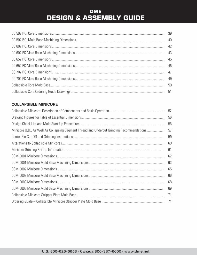
COLLAPSIBLE MINICORE
Collapsible Minicore: Description of Components and Basic Operation ................................................................ 52
Drawing Figures for Table of Essential Dimensions ................................................................................................ 56
Design Check List and Mold Start-Up Procedures .................................................................................................. 56
Minicore O.D., As Well As Collapsing Segment Thread and Undercut Grinding Recommendations..................... 57
Center Pin Cut-Off and Grinding Instructions .......................................................................................................... 59
Alterations to Collapsible Minicores ....................................................................................................................... 60
Minicore Grinding Set-Up Information .................................................................................................................... 61
CCM-0001 Minicore Dimensions ............................................................................................................................. 62
CCM-0001 Minicore Mold Base Machining Dimensions ........................................................................................ 63
CCM-0002 Minicore Dimensions ............................................................................................................................ 65
CCM-0002 Minicore Mold Base Machining Dimensions ........................................................................................ 66
CCM-0003 Minicore Dimensions ............................................................................................................................ 68
CCM-0003 Minicore Mold Base Machining Dimensions ........................................................................................ 69
Collapsible Minicore Stripper Plate Mold Base ...................................................................................................... 71
Ordering Guide – Collapsible Minicore Stripper Plate Mold Base ......................................................................... 71
DME
Collapsible Core
www.dme.net
1
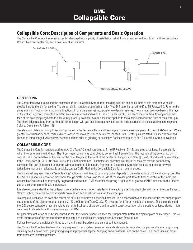
Collapsible Core: Description of Components and Basic Operation The Collapsible Core is a three-unit assembly designed for simplicity of installation, reliability in operation and long life. The three units are a
Collapsible Core, center pin, and a positive collapse sleeve.
POSITIVE COLLAPSE SLEEVE
CENTER PIN
COLLAPSIBLE CORE
CENTER PIN The Center Pin serves to expand the segments of the Collapsible Core to their molding position and holds them at this diameter. A hole is
provided inside the pin for cooling. The center pin is manufactured of a high alloy Type D-6 steel hardened to 60 to 65 Rockwell C. Refer to the
pin grinding instructions for machining directions. In use the pin must incorporate two design features. The pin must protrude beyond the face
of the collapsing core segments by certain amounts (refer to Dimension F, Table 1-1). This protrusion keeps material from flowing under the
face of the collapsing segments to ensure they properly collapse. A radius must be applied to the outside corner at the front of the center pin.
The sharp edge resulting from cutting the pin to length will gall and subsequently destroy the inside surfaces of the collapsing core segments
(refer to Dimension R, Table 1-1).
The standard plate machining dimensions provided in the Technical Data and Drawings assume a maximum pin protrusion of .075 inches. When
greater protrusion is needed, certain dimensions in the mold base must be altered; consult DME. Center pins are fitted to a specific core and
cannot be interchanged. Always verify serial numbers prior to grinding or assembly. Replacement pins to fit a Collapsible Core are available.
COLLAPSIBLE COREThe Collapsible Core is manufactured from A.I.S.I. Type A-2 steel hardened to 51 to 57 Rockwell C. It is designed to collapse independently
when the center pin is withdrawn. The fit between segments is controlled to permit flash free molding. The location of the core on its pin is
critical. The distance between the back of the core flange and the front of the center pin flange (Head Space) is critical and must be maintained.
If the Head Space (1.938 ±.005 on a CC 202 PC) is not maintained, unsatisfactory operation will result, or the core may be permanently
damaged. The unit is designed to operate without benefit of lubrication. Treating the Collapsible Core with an alloying process for wear
reduction or corrosion resistance is possible; contact DME. Plating the Collapsible Core is not recommended.
The individual segments have a “self-cleaning” action and will tend to carry any dirt or deposits to the outer surface of the collapsing core. The
first 50 to 100 shots in operation may show foreign matter deposits on the inside of the molded part. Prior to final assembly of the mold, the
Collapsible Core should be thoroughly degreased and cleaned. DME recommends giving a light wipe of grease or PTFE lubricant to the tapered
end of the center pin for break-in purposes.
It is also recommended that the collapsing core be free to turn when installed in the ejector plate. This slight play will permit the core flange to
“float” slightly, therefore helping it find its own center, and equalizing wear on the center pin.
To completely collapse the core, the center pin must be withdrawn a specified amount. This distance between the back of the rear support plate
and the front of the ejector retainer plate is 2.187 ±.005 for the Type CC-202-PC. It varies for different models of the core. This dimension and
the .207 deep counterbore must be held to permit full collapse of the core and to permit correct operation of the positive collapse sleeve. If it is
necessary to deviate from this dimension, consult DME.
Stripper plate actuation must be sequenced so that the cylinders have returned the stripper plate before the ejector plate has returned. This will
avoid interference of the stripper ring with the core and possible core damage (see Sequence Description).
Collapsible cores are individually fitted to a matching numbered pin, and cannot be interchanged.
The Collapsible Core has twelve collapsing segments. The molding diameter may indicate an out-of-round or stepped condition after grinding.
This may be due to an over-tight grinding ring or improper headspace. Stepping and/or witness lines on the core O.D. or core face can result
from excessive injection pressure.

DME
Collapsible Core
www.dme.net
2
POSITIVE COLLAPSE SLEEVE The Positive Collapse Sleeve (PC sleeve) is designed to function when the Collapsible Core fails to collapse independently upon withdrawal
of the center pin. In normal operation, the PC sleeve is not functioning. It is essential to have such a unit for maximum safety and reliability in
automatic and semi-automatic operation. Under no circumstances should a mold be placed into automatic operation without the use of the
PC sleeve.
The PC sleeve is uncomplicated in operation. An angular surface on the inside of the front edge of the PC sleeve will engage a matching angular
surface on the outside of the Collapsible Core should the un-collapsed core be moved forward in the PC sleeve. This interference action is
achieved by restricting the travel of the PC sleeve to an amount less than the forward travel of the Collapsible Core.
It is essential that no variation from the dimension given should be permitted between the rear of the back support plate and the front of the
ejector retainer plate. The .207 +.003-.002 deep counterbore must also be maintained. Do not deviate from these dimensions without prior approval of DME. Any variation from these dimensions will adversely affect the operation of the PC sleeve and may cause destruction of the core.
PC sleeves are interchangeable between different serial numbers of the same catalog number (size) core.
Desired Sequence of Operation of Collapsible Core for Automatic Mold Operation As seen on each “Mold Base Machining Dimension” sheet in the Collapsible Core Technical Data Book, the cross section depicts a typical
Collapsible Core mold design. The Collapsible Core is mounted in the ejector retainer plate; the center pin is mounted in a bottom clamp plate.
An extended stripper plate has been incorporated for proper ejection and cylinders are shown installed for the last stage of the required
two-stage ejection. Also vital to the design is the use of guided ejection.
The molding sequence can easily be followed by starting with the opening of the press. The press opens and the mold parts at the main parting
line. When sufficient mold open is achieved, the ejector plate assembly is moved forward by mechanical or hydraulic knockouts of the press.
The ejector plate assembly with the collapsing core is moving forward the necessary stroke required to move the core off of the center pin and
collapse the core (this is the first stage of ejection).
If the segments of the core fail to collapse for any reason during this stage, the positive collapse sleeve will come into play and ensure the start
of the collapse. In addition, the stripper plate and ejector plate assembly move together because of the return pins located directly under the
stripper plate. This simultaneous movement continues until the ejector plate assembly is full forward. At this point, a limit switch is actuated.
This in turn actuates the cylinders to take over and to continue to move the stripper plate with the stripper insert, moving the part away from the
collapsed core (second stage).
When automatic part stripping is required, means must be provided for carrying the molded part off of the collapsed core at the completion of
the ejector stroke. This is commonly done by providing a ring projection (.010 × .010 min.) on the face of the stripper insert. Shock dislodges the
part from this ring and permits it to drop out of the mold at the end of the stripper stroke. The part must not drag over the core. When removing
the part manually, the stripper ring and the cylinders are not required.
Please note that the stripper plate actuation must be sequenced so that the cylinders have returned the stripper plate before the ejector plates
are returned. This applies to all parts whether through molded or not. The stripper plate must always be returned to its original position before
re-expanding the core. This will avoid interference of the stripper insert with the core and possible core damage.
When the top face of the Collapsible Core shuts off against the cavity, all cores must be ground to the same overall length. In addition,
whenever this condition exists, an early ejector return must be employed. The early ejector return will ensure that the core is expanded before
the mold closes at the parting line.
DME
Collapsible Core
www.dme.net
3
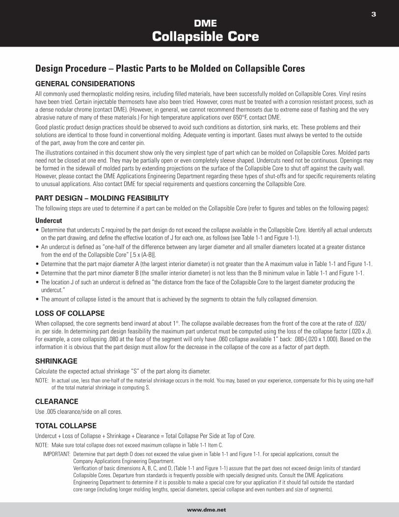
Design Procedure – Plastic Parts to be Molded on Collapsible Cores GENERAL CONSIDERATIONS All commonly used thermoplastic molding resins, including filled materials, have been successfully molded on Collapsible Cores. Vinyl resins
have been tried. Certain injectable thermosets have also been tried. However, cores must be treated with a corrosion resistant process, such as
a dense nodular chrome (contact DME). (However, in general, we cannot recommend thermosets due to extreme ease of flashing and the very
abrasive nature of many of these materials.) For high temperature applications over 650°F, contact DME.
Good plastic product design practices should be observed to avoid such conditions as distortion, sink marks, etc. These problems and their
solutions are identical to those found in conventional molding. Adequate venting is important. Gases must always be vented to the outside
of the part, away from the core and center pin.
The illustrations contained in this document show only the very simplest type of part which can be molded on Collapsible Cores. Molded parts
need not be closed at one end. They may be partially open or even completely sleeve shaped. Undercuts need not be continuous. Openings may
be formed in the sidewall of molded parts by extending projections on the surface of the Collapsible Core to shut off against the cavity wall.
However, please contact the DME Applications Engineering Department regarding these types of shut-offs and for specific requirements relating
to unusual applications. Also contact DME for special requirements and questions concerning the Collapsible Core.
PART DESIGN – MOLDING FEASIBILITY The following steps are used to determine if a part can be molded on the Collapsible Core (refer to figures and tables on the following pages):
Undercut Determine that undercuts C required by the part design do not exceed the collapse available in the Collapsible Core. Identify all actual undercuts
on the part drawing, and define the effective location of J for each one, as follows (see Table 1-1 and Figure 1-1).
An undercut is defined as “one-half of the difference between any larger diameter and all smaller diameters located at a greater distance
from the end of the Collapsible Core” [.5 x (A-B)].
Determine that the part major diameter A (the largest interior diameter) is not greater than the A maximum value in Table 1-1 and Figure 1-1.
Determine that the part minor diameter B (the smaller interior diameter) is not less than the B minimum value in Table 1-1 and Figure 1-1.
The location J of such an undercut is defined as “the distance from the face of the Collapsible Core to the largest diameter producing the
undercut.”
The amount of collapse listed is the amount that is achieved by the segments to obtain the fully collapsed dimension.
LOSS OF COLLAPSE When collapsed, the core segments bend inward at about 1°. The collapse available decreases from the front of the core at the rate of .020/
in. per side. In determining part design feasibility the maximum part undercut must be computed using the loss of the collapse factor (.020 x J).
For example, a core collapsing .080 at the face of the segment will only have .060 collapse available 1” back: .080-(.020 x 1.000). Based on the
information it is obvious that the part design must allow for the decrease in the collapse of the core as a factor of part depth.
SHRINKAGE Calculate the expected actual shrinkage “S” of the part along its diameter.
NOTE: In actual use, less than one-half of the material shrinkage occurs in the mold. You may, based on your experience, compensate for this by using one-half
of the total material shrinkage in computing S.
CLEARANCE Use .005 clearance/side on all cores.
TOTAL COLLAPSE Undercut + Loss of Collapse + Shrinkage + Clearance = Total Collapse Per Side at Top of Core.
NOTE: Make sure total collapse does not exceed maximum collapse in Table 1-1 Item C.
IMPORTANT: Determine that part depth D does not exceed the value given in Table 1-1 and Figure 1-1. For special applications, consult the
Company Applications Engineering Department.
Verification of basic dimensions A, B, C, and D, (Table 1-1 and Figure 1-1) assure that the part does not exceed design limits of standard
Collapsible Cores. Departure from standards is frequently possible with specially designed units. Consult the DME Applications
Engineering Department to determine if it is possible to make a special core for your application if it should fall outside the standard
core range (including longer molding lengths, special diameters, special collapse and even numbers and size of segments).
DME
Collapsible Core
www.dme.net
4
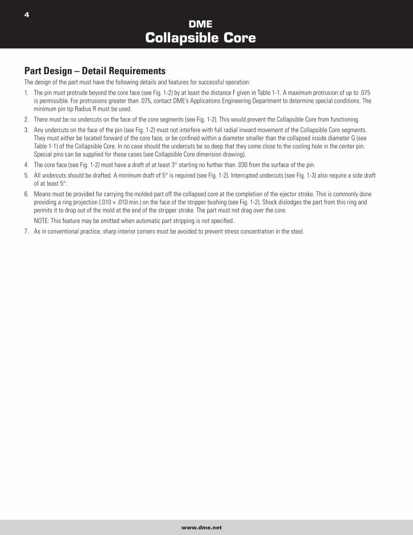
Part Design – Detail Requirements The design of the part must have the following details and features for successful operation:
1. The pin must protrude beyond the core face (see Fig. 1-2) by at least the distance F given in Table 1-1. A maximum protrusion of up to .075
is permissible. For protrusions greater than .075, contact DME’s Applications Engineering Department to determine special conditions. The
minimum pin tip Radius R must be used.
2. There must be no undercuts on the face of the core segments (see Fig. 1-2). This would prevent the Collapsible Core from functioning.
3. Any undercuts on the face of the pin (see Fig. 1-2) must not interfere with full radial inward movement of the Collapsible Core segments.
They must either be located forward of the core face, or be confined within a diameter smaller than the collapsed inside diameter G (see
Table 1-1) of the Collapsible Core. In no case should the undercuts be so deep that they come close to the cooling hole in the center pin.
Special pins can be supplied for these cases (see Collapsible Core dimension drawing).
4. The core face (see Fig. 1-2) must have a draft of at least 3° starting no further than .030 from the surface of the pin.
5. All undercuts should be drafted. A minimum draft of 5° is required (see Fig. 1-2). Interrupted undercuts (see Fig. 1-3) also require a side draft
of at least 5°.
6. Means must be provided for carrying the molded part off the collapsed core at the completion of the ejector stroke. This is commonly done
providing a ring projection (.010 × .010 min.) on the face of the stripper bushing (see Fig. 1-2). Shock dislodges the part from this ring and
permits it to drop out of the mold at the end of the stripper stroke. The part must not drag over the core.
NOTE: This feature may be omitted when automatic part stripping is not specified.
7. As in conventional practice, sharp interior corners must be avoided to prevent stress concentration in the steel.
DME
Collapsible Core
www.dme.net
5
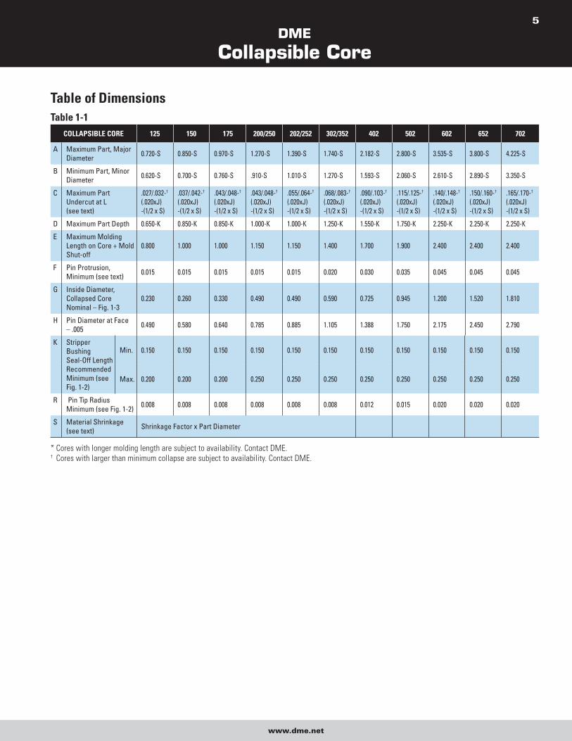
Table of Dimensions Table 1-1
COLLAPSIBLE CORE 125 150 175 200/250 202/252 302/352 402 502 602 652 702
A Maximum Part, Major Diameter 0.720-S 0.850-S 0.970-S 1.270-S 1.390-S 1.740-S 2.182-S 2.800-S 3.535-S 3.800-S 4.225-S
B Minimum Part, Minor Diameter 0.620-S 0.700-S 0.760-S .910-S 1.010-S 1.270-S 1.593-S 2.060-S 2.610-S 2.890-S 3.350-S
C Maximum Part Undercut at L (see text)
.027/.032-† (.020xJ) -(1/2 x S)
.037/.042-† (.020xJ) -(1/2 x S)
.043/.048-† (.020xJ) -(1/2 x S)
.043/.048-† (.020xJ) -(1/2 x S)
.055/.064-† (.020xJ) -(1/2 x S)
.068/.083-† (.020xJ) -(1/2 x S)
.090/.103-† (.020xJ) -(1/2 x S)
.115/.125-† (.020xJ) -(1/2 x S)
.140/.148-† (.020xJ) -(1/2 x S)
.150/.160-† (.020xJ) -(1/2 x S)
.165/.170-† (.020xJ) -(1/2 x S)
D Maximum Part Depth 0.650-K 0.850-K 0.850-K 1.000-K 1.000-K 1.250-K 1.550-K 1.750-K 2.250-K 2.250-K 2.250-K
E Maximum Molding Length on Core + Mold Shut-off
0.800 1.000 1.000 1.150 1.150 1.400 1.700 1.900 2.400 2.400 2.400
F Pin Protrusion, Minimum (see text) 0.015 0.015 0.015 0.015 0.015 0.020 0.030 0.035 0.045 0.045 0.045
G Inside Diameter, Collapsed Core Nominal – Fig. 1-3
0.230 0.260 0.330 0.490 0.490 0.590 0.725 0.945 1.200 1.520 1.810
H Pin Diameter at Face – .005 0.490 0.580 0.640 0.785 0.885 1.105 1.388 1.750 2.175 2.450 2.790
K Stripper Bushing Seal-Off Length Recommended Minimum (see Fig. 1-2)
Min. 0.150 0.150 0.150 0.150 0.150 0.150 0.150 0.150 0.150 0.150 0.150
Max. 0.200 0.200 0.200 0.250 0.250 0.250 0.250 0.250 0.250 0.250 0.250
R Pin Tip Radius Minimum (see Fig. 1-2) 0.008 0.008 0.008 0.008 0.008 0.008 0.012 0.015 0.020 0.020 0.020
S Material Shrinkage (see text) Shrinkage Factor x Part Diameter
* Cores with longer molding length are subject to availability. Contact DME. † Cores with larger than minimum collapse are subject to availability. Contact DME.
DME
Collapsible Core
www.dme.net
6
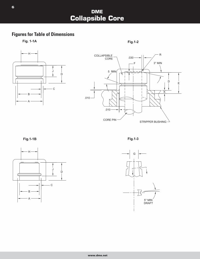
Figures for Table of Dimensions
H
H
B
A
C
B
A
C
JD
JD
E
CORE PINSTRIPPER BUSHING
.010
COLLAPSIBLECORE
5 ° MIN
.010
3° MIN
.030
F
D
K
R
5° MINDRAFT
G
Fig. 1-1A
Fig.1-1B
Fig.1-2
Fig.1-3
DME
Collapsible Core
www.dme.net
7
Design Check List and Mold Start-up Procedures Things to look for in mold design and in checking out molds prior to operation:
1. Use guided ejector plates and support ring around center pin between ejector plate and ejector housing or back clamp plate (doughnut
around pin).
2. First break to occur at main parting line. Use springs to assure.
3. Return pins to be located under, not through, stripper plate.
4. Ejector travel to specification, stamp on edge of ejector plate.
5. Secondary stripper actuation only after full ejector plate travel. Use properly set micro-switch or other means. Stripper-plate must return
fully before ejector plate begins return (see Sequence Description).
6. When top face of Collapsible Core segments shut off against cavity (for some parts with through holes), all cores must be ground to same
length overall. Normal core tolerance of plus or minus .003 is inadequate. Whenever the above condition exists, an early ejector return
system must be used. Clearance between end of core segments and cavity to be .0005/.001. Do not pre-load.
7. Good venting is essential, preferably to outside of mold at parting line.
8. Clearance between core and stripper bushing (.0010/.0015 total) on diameter at room temperature. No tapered mold seal-off below thread
or configuration. Measure O.D. of core at stripper bushing when core is installed in mold with stripper plate removed.
9. Verify for center pin protrusion and pin tip radius. Examine pins for evidence of any de-temper of pin tip due to overheating in grinding.
10. Mounted core in ejector plate assembly to be free to turn if part design allows.
11. Center pin and stripper bushing to be concentric. Water line baffle in center pin sometimes tends to throw pin off, or pin may be
improperly mounted.
12. Positive collapse sleeve to travel freely, both when starting up and when mold is at operating temperature. Grease lightly.
13. Check finish on cores:
– Surface finish and polish.
– Undercuts and back-hooks in direction of collapse due to improper grinding.
– Compliance with proper design procedures.
14. Observe proper care in dry cycling:
– Plate cocking or bounce.
– Audible sounds or visible indications of friction, misalignment or scoring.
– Sequence of motions (see Sequence Description).
– Positive collapse action.
15. Threads ground into Collapsible Core should not run out to a feather/knife edge.
16. Refer to Sequence Description for desired Sequence of Automatic Mold Operation.
DME
Collapsible Core
www.dme.net
8
Grinding Recommendations – Collapsible Core A – GENERAL 1. Cores and pins must be clean prior to assembly for grinding. A coating of lightweight rust preventive is recommended.
2. Assemble core to pin as specified in installation drawing, using three set screws (supplied) tightened against pin to prevent shifting during
grinding. Concentricity of core pin is extremely important.
NOTE: Cores are assembled prior to shipment, but must be re-set by grinder because of possibility of movement in transit.
3. During grinding, do not use air blast or water jet at high pressure for cooling since this may force grinding grit between segments.
4. Select a grinding wheel suitable for grinding A.I.S.I. type A2 Steel (air hardening tool steel) of approximately 55 Rockwell C.
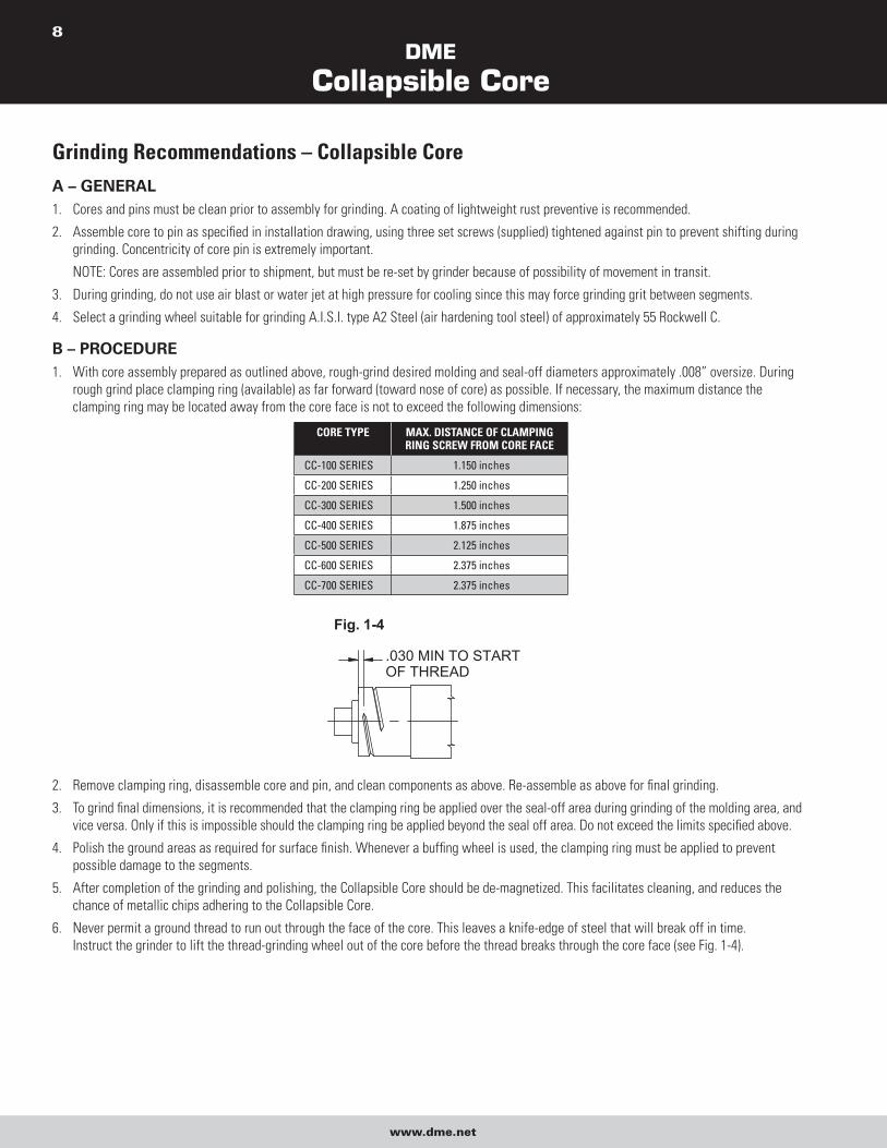
B – PROCEDURE 1. With core assembly prepared as outlined above, rough-grind desired molding and seal-off diameters approximately .008” oversize. During
rough grind place clamping ring (available) as far forward (toward nose of core) as possible. If necessary, the maximum distance the
clamping ring may be located away from the core face is not to exceed the following dimensions:
CORE TYPE MAX. DISTANCE OF CLAMPING RING SCREW FROM CORE FACE
CC-100 SERIES 1.150 inches
CC-200 SERIES 1.250 inches
CC-300 SERIES 1.500 inches
CC-400 SERIES 1.875 inches
CC-500 SERIES 2.125 inches
CC-600 SERIES 2.375 inches
CC-700 SERIES 2.375 inches
.030 MIN TO STARTOF THREAD
Fig. 1-4
2. Remove clamping ring, disassemble core and pin, and clean components as above. Re-assemble as above for final grinding.
3. To grind final dimensions, it is recommended that the clamping ring be applied over the seal-off area during grinding of the molding area, and
vice versa. Only if this is impossible should the clamping ring be applied beyond the seal off area. Do not exceed the limits specified above.
4. Polish the ground areas as required for surface finish. Whenever a buffing wheel is used, the clamping ring must be applied to prevent
possible damage to the segments.
5. After completion of the grinding and polishing, the Collapsible Core should be de-magnetized. This facilitates cleaning, and reduces the
chance of metallic chips adhering to the Collapsible Core.
6. Never permit a ground thread to run out through the face of the core. This leaves a knife-edge of steel that will break off in time.
Instruct the grinder to lift the thread-grinding wheel out of the core before the thread breaks through the core face (see Fig. 1-4).
DME
Collapsible Core
www.dme.net
9
Grinding Instructions – Center Pin, D-6 Steel GENERAL DIRECTIONSD6 Steel is a high carbon, high chrome steel, hardened to over 60 Rockwell on the C scale. At all times grinding must be done under a coolant
flood, using a coolant suitable for hardened tool steels.
IMPORTANT: Lack of sufficient cooling, heavy cuts, rapid plunging or in-feeding, will result in overheating and a loss of hardness, or heat
checking and cracking.
The center pin has been ground on its own centers. The Collapsible Core has been ground true to the centers of the pin supplied with the unit.
For set-up, refer to Grinding Recommendations – Collapsible Core.
Step 1 Wire EDM cut-off is preferred. Cutting off the center pin can also be done with a resin cut-off wheel, in a universal grinder with the center pin
rotating and heavy flood coolant. Use coolant suitable for hardened tool steels.
When cutting off the tapered end: the flange is chucked and the long straight diameter beyond the flange is held in a steady rest, as close to
the taper as possible. Indicate true before cutting off. Leave .025-.035 stock for final facing. Flood coolant must be used.
When cutting off the flange end: the center pin can be chucked on the long straight diameter beyond the flange. Indicate true before cutting
off. Leave .025-.035 stock for final facing. Flood coolant must be used.
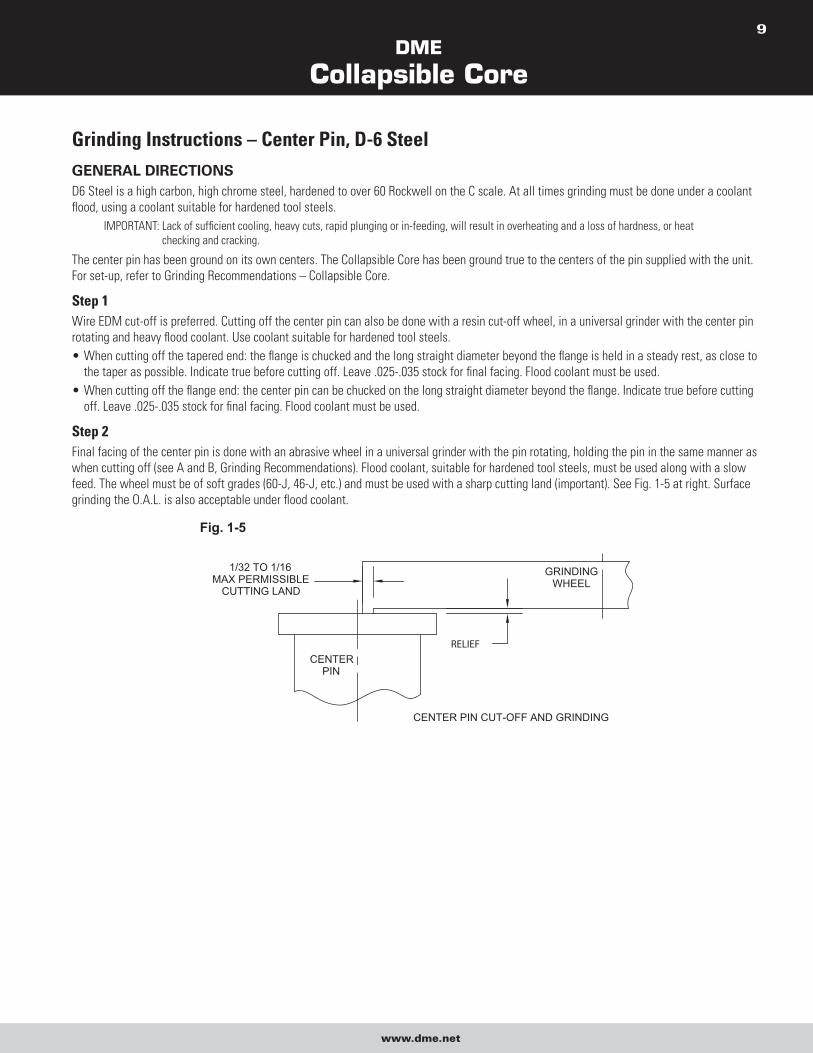
Step 2 Final facing of the center pin is done with an abrasive wheel in a universal grinder with the pin rotating, holding the pin in the same manner as
when cutting off (see A and B, Grinding Recommendations). Flood coolant, suitable for hardened tool steels, must be used along with a slow
feed. The wheel must be of soft grades (60-J, 46-J, etc.) and must be used with a sharp cutting land (important). See Fig. 1-5 at right. Surface
grinding the O.A.L. is also acceptable under flood coolant.
CENTERPIN
1/32 TO 1/16MAX PERMISSIBLE
CUTTING LAND
RELIEF
CENTER PIN CUT-OFF AND GRINDING
GRINDINGWHEEL
Fig. 1-5
DME
Collapsible Core
www.dme.net
10
Alterations to Collapsible Cores Occasionally a need arises to shorten the overall length of a Collapsible Core or to do additional grinding on a Collapsible Core after it has been
finish ground. In shortening the O.A.L. of a core, the following procedure should be used.
The core should be removed from its regular center pin and thoroughly cleaned. The core is then placed on a working pin for grinding. The
working pin has a standard taper ground on the front end and has centers both front and rear. Insert the working pin into the Collapsible Core
until the diameter of the core, when measured over the positive collapse bumps, coincides with this diameter as determined while the core is on
its own pin with the head space set.
When using a working pin do not attempt to locate the core for grinding by setting its standard head space. This will almost never be the correct
setting for the core since each core is individually custom fitted.
To shorten the core to a new length, a clamping ring is used and material is removed from the front of the core on a cylindrical grinder. The
grinding wheel goes through the entire material of the core segments and cuts into the working pin to ensure a clean front surface. Core
collapse will be decreased by .020 in./in. per side when O.A.L. is shortened.
It is obvious now why a working pin is used. If this grinding were performed on the core’s regular center pin, the taper would be destroyed.
When a core has to be re-ground after its thread profiles have been finished and the centers on the regular center pin have been removed,
again a working pin is used. The working pin is inserted into the core until the ground diameters of the core on the working pin coincide with
the ground diameters of the core as finished. Again, the core is fixtured using the three screws at the mounting flange and the segments are
held rigidly under a clamping ring. It is now possible to change the diameters on the working end of the core, or to deepen or enlarge the
thread profiles.
After all finish grinding and polishing operations on the core are completed, it is important to demagnetize the core to prevent the adhesion
of any metal particles that might find their way into cavities or between the segments during molding operations.
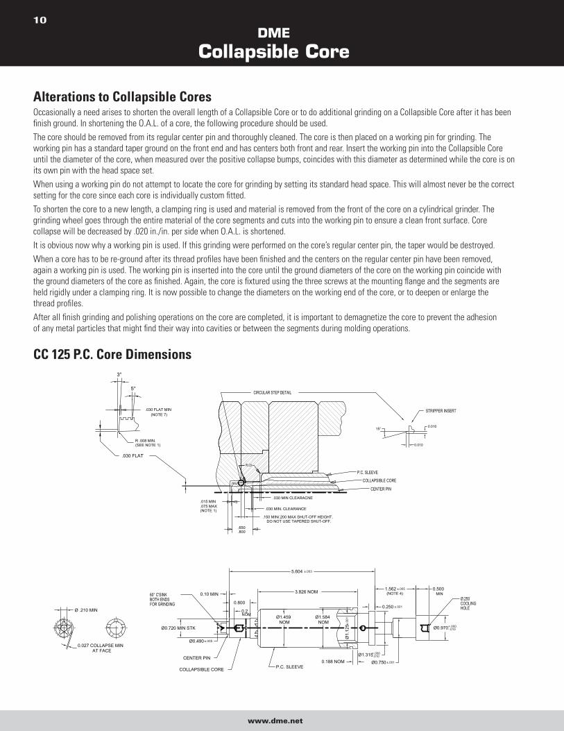
CC 125 P.C. Core Dimensions
COLLAPSIBLE CORE
CENTER PIN
Ø0.490 ±.005
Ø0.720 MIN STK
0.10 MIN
0.2
0.800
60° C'SINKBOTH ENDSFOR GRINDING
0.188 NOM
5.604 ±.003
Ø1.584NOM
Ø1.459NOM
P.C. SLEEVE
3.826 NOM
NOM
Ø1.315+.000-.010
Ø0.970+.000-.010
Ø0.750 ±.001
0.5001.562 ±.005(NOTE 4)
0.250 ±.001
Ø.250COOLINGHOLE
MIN
.030 FLAT
(NOTE 7).030 FLAT MIN
5°
3°
.150 MIN/.200 MAX SHUT-OFF HEIGHT.DO NOT USE TAPERED SHUT-OFF.
P.C. SLEEVE
.030 MIN CLEARACNE
.030 MIN. CLEARANCE
R.03
CIRCULAR STEP DETAIL
COLLAPSIBLE CORE
CENTER PIN
0.010
STRIPPER INSERT
15°
0.010
Ø1.
125±
.001
(NOTE 1)
0.027 COLLAPSE MINAT FACE
R .008 MIN.(SEE NOTE 1)
.015 MIN
.075 MAX
.650
.800
Ø .210 MIN
DME
Collapsible Core
www.dme.net
11
1.150MAX
Ø1.88Ø2.63
1.562(NOTE 4)
INDICATE HERE FORGRINDING .003 MAX T.I.R.
SET-UP FOR GRINDINGREFER TO GRINDING INFORMATION
USE SCREWS TOALIGN CORE ON PIN
CENTER SCREWS ONMIDDLE OF LARGESEGMENT
±.005
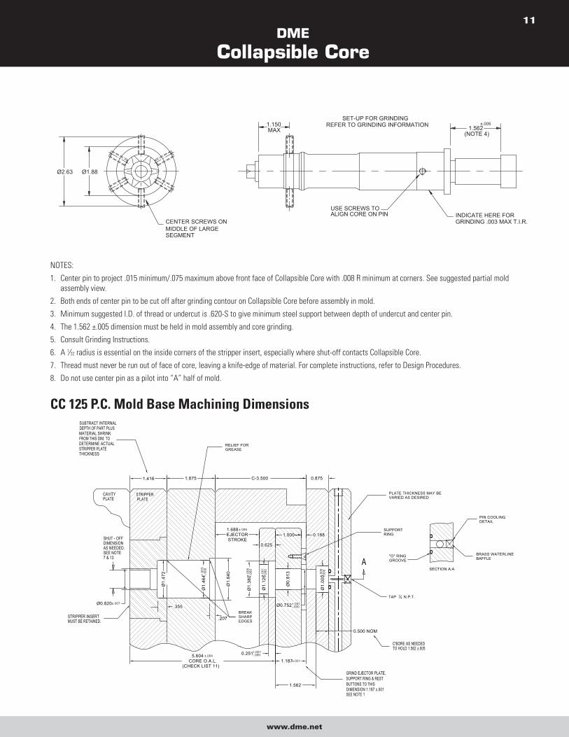
NOTES:
1. Center pin to project .015 minimum/.075 maximum above front face of Collapsible Core with .008 R minimum at corners. See suggested partial mold
assembly view.
2. Both ends of center pin to be cut off after grinding contour on Collapsible Core before assembly in mold.
3. Minimum suggested I.D. of thread or undercut is .620-S to give minimum steel support between depth of undercut and center pin.
4. The 1.562 ±.005 dimension must be held in mold assembly and core grinding.
5. Consult Grinding Instructions.
6. A 1⁄32 radius is essential on the inside corners of the stripper insert, especially where shut-off contacts Collapsible Core.
7. Thread must never be run out of face of core, leaving a knife-edge of material. For complete instructions, refer to Design Procedures.
8. Do not use center pin as a pilot into “A” half of mold.
CC 125 P.C. Mold Base Machining Dimensions
0.875
0.625
5.604 ±.004
CORE O.A.L.(CHECK LIST 11)
Ø1.
464+.
003
-.000
STRIPPER INSERTMUST BE RETAINED.
Ø1.
472
Ø0.820±.007
0.251+.001-.000
1.562
1.187±.001
Ø1.
380+.
005
-.000
Ø1.
126+.
001
-.000
Ø1.
640
Ø1.
000+.
005
-.000
Ø0.
813
Ø0.752+.001-.000
1.875
SUBTRACT INTERNALDEPTH OF PART PLUSMATERIAL SHRINKFROM THIS DIM. TODETERMINE ACTUALSTRIPPER PLATE THICKNESS
CAVITYPLATE
STRIPPER PLATE
C-3.500
1.688±.005
EJECTORSTROKE
1.000 0.188
C'BORE AS NEEDEDTO HOLD 1.562 ±.005
GRIND EJECTOR PLATE,SUPPORT RING & RESTBUTTONS TO THIS DIMENSION 1.187 ±.001SEE NOTE 1
A
1.416
PLATE THICKNESS MAY BE VARIED AS DESIRED
SUPPORTRING
BREAKSHARPEDGES
0.500 NOM
RELIEF FORGREASE
TAP 14 N.P.T.
BRASS WATERLINEBAFFLE
PIN COOLINGDETAIL
SECTION A:A
"O" RINGGROOVE
SHUT - OFFDIMENSIONAS NEEDED.SEE NOTE7 & 13
.207
.355
DME
Collapsible Core
www.dme.net
12
CYLINDERS RECOMMENDED FORAUTOMATIC MOLD OPERATION
(CHECK LIST 5)
PARTING LINEGUIDED EJECTION
MOLDED PART
SEE NOTE 2
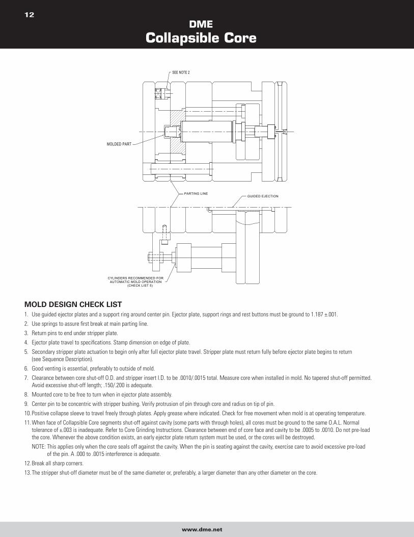
MOLD DESIGN CHECK LIST 1. Use guided ejector plates and a support ring around center pin. Ejector plate, support rings and rest buttons must be ground to 1.187 ±.001.
2. Use springs to assure first break at main parting line.
3. Return pins to end under stripper plate.
4. Ejector plate travel to specifications. Stamp dimension on edge of plate.
5. Secondary stripper plate actuation to begin only after full ejector plate travel. Stripper plate must return fully before ejector plate begins to return
(see Sequence Description).
6. Good venting is essential, preferably to outside of mold.
7. Clearance between core shut-off O.D. and stripper insert I.D. to be .0010/.0015 total. Measure core when installed in mold. No tapered shut-off permitted.
Avoid excessive shut-off length; .150/.200 is adequate.
8. Mounted core to be free to turn when in ejector plate assembly.
9. Center pin to be concentric with stripper bushing. Verify protrusion of pin through core and radius on tip of pin.
10. Positive collapse sleeve to travel freely through plates. Apply grease where indicated. Check for free movement when mold is at operating temperature.
11. When face of Collapsible Core segments shut-off against cavity (some parts with through holes), all cores must be ground to the same O.A.L. Normal
tolerance of ±.003 is inadequate. Refer to Core Grinding Instructions. Clearance between end of core face and cavity to be .0005 to .0010. Do not pre-load
the core. Whenever the above condition exists, an early ejector plate return system must be used, or the cores will be destroyed.
NOTE: This applies only when the core seals off against the cavity. When the pin is seating against the cavity, exercise care to avoid excessive pre-load
of the pin. A .000 to .0015 interference is adequate.
12. Break all sharp corners.
13. The stripper shut-off diameter must be of the same diameter or, preferably, a larger diameter than any other diameter on the core.
DME
Collapsible Core
www.dme.net
13
CC 150 P.C. Core Dimensions
.030 FLAT
(NOTE 7).030 FLAT MIN
5°
3°
.150 MIN/.200 MAX SHUT-OFF HEIGHT.DO NOT USE TAPERED SHUT-OFF.
P.C. SLEEVE
.030 MIN CLEARANCE
.030 MIN. CLEARANCE
R.03
CIRCULAR STEP DETAIL
COLLAPSIBLE CORE
CENTER PIN
0.010
STRIPPER INSERT
15°
0.010
(NOTE 1)
R .008 MIN.(SEE NOTE 1)
.015 MIN.075 MAX
.8501.000
Ø0.850MIN STK
0.580 ±.005
1.625 ±.005
.685
.125
4.270 NOM
Ø1.
600
NO
M
Ø1.
305
+.00
0-.0
01
Ø1.
610
+.00
0-.0
10
Ø0.780 ±.001
Ø1.
000
+.00
0-.0
10
Ø1.
750
NO
M
0.239NOM
1.000C'SINKBOTH ENDSFOR GRINDING 0.6
MIN
1.625 ±.005
(NOTE 4)
Ø.312COOLING HOLE
0.250 ±.001
0.188NOM
6.615 ±.003
P.C. SLEEVECOLLAPSIBLE CORE
CENTER PIN
.260
.037MIN
1.625 ±.005
(NOTE 4)
USE SCREWS TOALIGN CORE ON PIN INDICATE HERE FOR
GRINDING .003 MAX T.I.R.
SET-UP GRINDINGREFER TO GRINDINGINFORMATION
CENTER SCREWS ONMIDDLE OF LARGESEGMENT
1.125 MAX
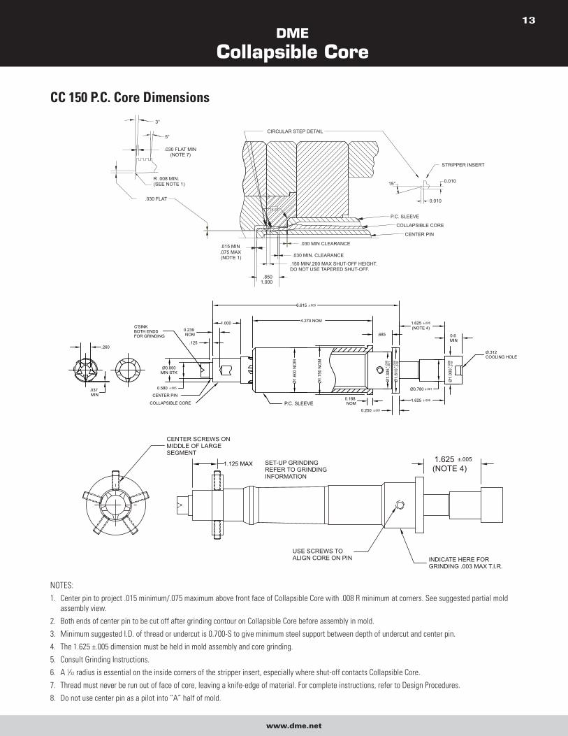
NOTES:
1. Center pin to project .015 minimum/.075 maximum above front face of Collapsible Core with .008 R minimum at corners. See suggested partial mold
assembly view.
2. Both ends of center pin to be cut off after grinding contour on Collapsible Core before assembly in mold.
3. Minimum suggested I.D. of thread or undercut is 0.700-S to give minimum steel support between depth of undercut and center pin.
4. The 1.625 ±.005 dimension must be held in mold assembly and core grinding.
5. Consult Grinding Instructions.
6. A 1⁄32 radius is essential on the inside corners of the stripper insert, especially where shut-off contacts Collapsible Core.
7. Thread must never be run out of face of core, leaving a knife-edge of material. For complete instructions, refer to Design Procedures.
8. Do not use center pin as a pilot into “A” half of mold.
DME
Collapsible Core
www.dme.net
14
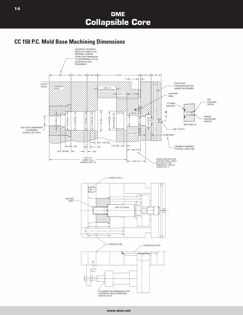
CC 150 P.C. Mold Base Machining Dimensions
1.625 ±.005
EJECTOR STROKE
1.625 ±.005
1.865
SUBTRACT INTERNALDEPTH OF PART PLUSMATERIAL SHRINKFROM THIS DIMENSIONTO DETERMINE ACTUALSTRIPPER PLATE THICKNESS.
C-3.687.8751.375 .875 .875
6.615 ±.003
CORE O.A.L.(CHECK LIST 11)
Ø1.
020±
.005
Ø1.
616±
.005
Ø1.
604+.
004
-.000
Ø1.
626
Ø1.
604+.
004
-.000
Ø1.
780
Ø1.
306+.
001
-.000
Ø1.
630+.
005
-.000
Ø0.94
Ø0.781+.001-.000
Ø1.
030+.
005
-.000
0.251+.001-.000
0.438 NOM
C'BORE AS NEEDEDTO HOLD 1.625 ±.005
1.0000.875 ±.003
0.207 +.003-.000
.500
.895 MIN .250
.250
SHUT OFF DIMENSIONAS NEEDED
(CHECK LIST 7&13)
SUPPORTRING
THIS PLATE THICKNESS MAY BEVARIED AS DESIRED
1.188±.005
STRIPPERPLATE
CAVITYPLATE
GRIND EJECTOR PLATE,SUPPORT RING, & RESTBUTTONS TO THISDIMENSION 1.188±.001(CHECK LIST 1)
"O" RINGGROOVE
SECTION A:A
PIN COOLINGDETAIL
BRASS WATERLINEBAFFLE
A
0.188
TAP 1 4 N.P.T.
MOLDEDPART
(CHECK LIST 2)
NOT TO SCALE
CYLINDERS RECOMMENDED FORAUTOMATIC MOLD OPERATION(CHECK LIST 5)
PARTING LINE GUIDED EJECTION
DME
Collapsible Core
www.dme.net
15
MOLD DESIGN CHECK LIST 1. Use guided ejector plates and a support ring around center pin. Ejector plate, support rings and rest buttons must be ground to 1.187 ±.001.
2. Use springs to assure first break at main parting line.
3. Return pins to end under stripper plate.
4. Ejector plate travel to specifications. Stamp dimension on edge of plate.
5. Secondary stripper plate actuation to begin only after full ejector plate travel. Stripper plate must return fully before ejector plate begins to
return (see Sequence Description).
6. Good venting is essential, preferably to outside of mold.
7. Clearance between core shut-off O.D. and stripper insert I.D. to be .0010/.0015 total. Measure core when installed in mold. No tapered
shut-off permitted. Avoid excessive shut-off length; .150/.200 is adequate.
8. Mounted core to be free to turn when in ejector plate assembly.
9. Center pin to be concentric with stripper bushing. Verify protrusion of pin through core and radius on tip of pin.
10. Positive collapse sleeve to travel freely through plates. Apply grease where indicated. Check for free movement when mold is at operating
temperature.
11. When face of Collapsible Core segments shut-off against cavity (some parts with through holes), all cores must be ground to the same
O.A.L. Normal tolerance of ±.003 is inadequate. Refer to Core Grinding Instructions. Clearance between end of core face and cavity to be
.0005 to .0010. Do not pre-load the core. Whenever the above condition exists, an early ejector plate return system must be used, or the
cores will be destroyed.
NOTE: This applies only when the core seals off against the cavity. When the pin is seating against the cavity exercise care to avoid
excessive pre-load of the pin. A .000 to .0015 interference is adequate.
12. Break all sharp corners.
13. The stripper shut-off diameter must be of the same diameter, or preferably, a larger diameter than any other diameter on the core.
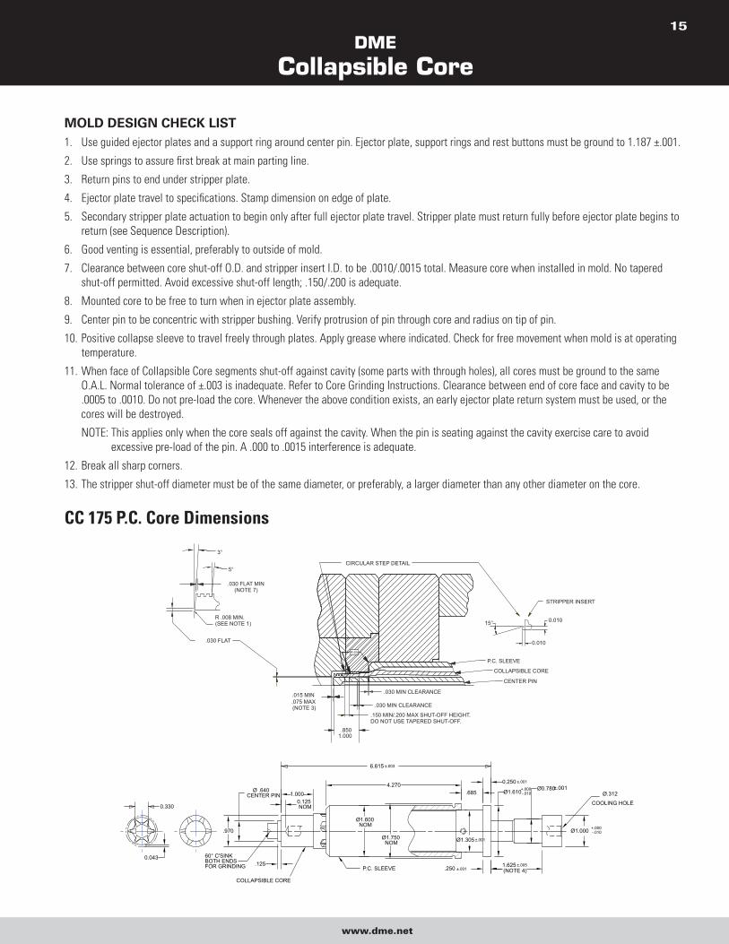
CC 175 P.C. Core Dimensions
.030 FLAT
(NOTE 7).030 FLAT MIN
5°
3°
.150 MIN/.200 MAX SHUT-OFF HEIGHT.DO NOT USE TAPERED SHUT-OFF.
P.C. SLEEVE
.030 MIN CLEARANCE
.030 MIN CLEARANCE
R.03
CIRCULAR STEP DETAIL
COLLAPSIBLE CORE
CENTER PIN
0.010
STRIPPER INSERT
15°
0.010
(NOTE 3)
R .008 MIN.(SEE NOTE 1)
.015 MIN.075 MAX
.8501.000
.970
.685Ø .640CENTER PIN
.125 1.625 ±.005(NOTE 4)
4.270
Ø1.600NOM
.250 ±.001
Ø1.610+.000-.010
Ø0.780±.001
Ø1.000 +.000-.010
Ø.312
COOLING HOLE
Ø1.750NOM
P.C. SLEEVE
COLLAPSIBLE CORE
0.125NOM
1.000
0.250 ±.001
Ø1.305 ±.001
60° C'SINKBOTH ENDSFOR GRINDING
0.043
0.330
6.615 ±.003
DME
Collapsible Core
www.dme.net
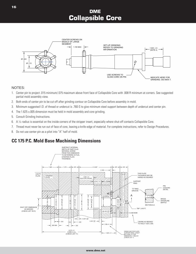
16
1.625 ±.004
(NOTE 4)
INDICATE HERE FORGRINDING .003 MAX T.
USE SCREWS TOALIGN CORE ON PIN
SET-UP GRINDINGREFER TO GRINDINGINFORMATION
CENTER SCREWS ONMIDDLE OF LARGESEGMENT
Ø1.113
Ø1.824
1.150 MAX
NOTES:1. Center pin to project .015 minimum/.075 maximum above front face of Collapsible Core with .008 R minimum at corners. See suggested
partial mold assembly view.
2. Both ends of center pin to be cut off after grinding contour on Collapsible Core before assembly in mold.
3. Minimum suggested I.D. of thread or undercut is .760-S to give minimum steel support between depth of undercut and center pin.
4. The 1.625 ±.005 dimension must be held in mold assembly and core grinding.
5. Consult Grinding Instructions.
6. A 1⁄32 radius is essential on the inside corners of the stripper insert, especially where shut-off contacts Collapsible Core.
7. Thread must never be run out of face of core, leaving a knife-edge of material. For complete instructions, refer to Design Procedures.
8. Do not use center pin as a pilot into “A” half of mold.
CC 175 P.C. Mold Base Machining Dimensions
1.625 ±.005
EJECTOR STROKE
1.625 ±.005
1.865
SUBTRACT INTERNALDEPTH OF PART PLUSMATERIAL SHRINKFROM THIS DIMENSIONTO DETERMINE ACTUALSTRIPPER PLATE THICKNESS.
C-3.687.8751.375 .875 .875
6.615 ±.003
CORE O.A.L.(CHECK LIST 11)
Ø1.
156
±.00
5
Ø1.
616±
.005
Ø1.
604+.
004
-.000
Ø1.
626
Ø1.
604+.
004
-.000
Ø1.
780
Ø1.
306+.
001
-.000
Ø1.
630+.
005
-.000
Ø0.94
Ø0.781+.001-.000
Ø1.
030+.
005
-.000
0.251+.001-.000
0.438 NOM
C'BORE AS NEEDEDTO HOLD 1.625 ±.005
1.0000.875 ±.003
0.207 +.003-.000
.500
.895 MIN .250
.250
SHUT OFF DIMENSIONAS NEEDED
(CHECK LIST 7&13)
SUPPORTRING
THIS PLATE THICKNESS MAY BEVARIED AS DESIRED
1.188±.005
STRIPPERPLATE
CAVITYPLATE
GRIND EJECTOR PLATE,SUPPORT RING, & RESTBUTTONS TO THISDIMENSION 1.188±.001(CHECK LIST 1)
"O" RINGGROOVE
SECTION A:A
PIN COOLINGDETAIL
BRASS WATERLINEBAFFLE
A
0.188
TAP 14 N.P.T.
DME
Collapsible Core
www.dme.net
17
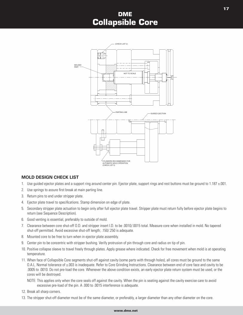
GUIDED EJECTIONPARTING LINE
AUTOMATIC MOLD OPERATION(CHECK LIST 5)
CYLINDERS RECOMMENDED FOR
NOT TO SCALE
(CHECK LIST 2)
MOLDEDPART
MOLD DESIGN CHECK LIST 1. Use guided ejector plates and a support ring around center pin. Ejector plate, support rings and rest buttons must be ground to 1.187 ±.001.
2. Use springs to assure first break at main parting line.
3. Return pins to end under stripper plate.
4. Ejector plate travel to specifications. Stamp dimension on edge of plate.
5. Secondary stripper plate actuation to begin only after full ejector plate travel. Stripper plate must return fully before ejector plate begins to
return (see Sequence Description).
6. Good venting is essential, preferably to outside of mold.
7. Clearance between core shut-off O.D. and stripper insert I.D. to be .0010/.0015 total. Measure core when installed in mold. No tapered
shut-off permitted. Avoid excessive shut-off length; .150/.250 is adequate.
8. Mounted core to be free to turn when in ejector plate assembly.
9. Center pin to be concentric with stripper bushing. Verify protrusion of pin through core and radius on tip of pin.
10. Positive collapse sleeve to travel freely through plates. Apply grease where indicated. Check for free movement when mold is at operating
temperature.
11. When face of Collapsible Core segments shut-off against cavity (some parts with through holes), all cores must be ground to the same
O.A.L. Normal tolerance of ±.003 is inadequate. Refer to Core Grinding Instructions. Clearance between end of core face and cavity to be
.0005 to .0010. Do not pre-load the core. Whenever the above condition exists, an early ejector plate return system must be used, or the
cores will be destroyed.
NOTE: This applies only when the core seals off against the cavity. When the pin is seating against the cavity exercise care to avoid
excessive pre-load of the pin. A .000 to .0015 interference is adequate.
12. Break all sharp corners.
13. The stripper shut-off diameter must be of the same diameter, or preferably, a larger diameter than any other diameter on the core.
DME
Collapsible Core
www.dme.net
18
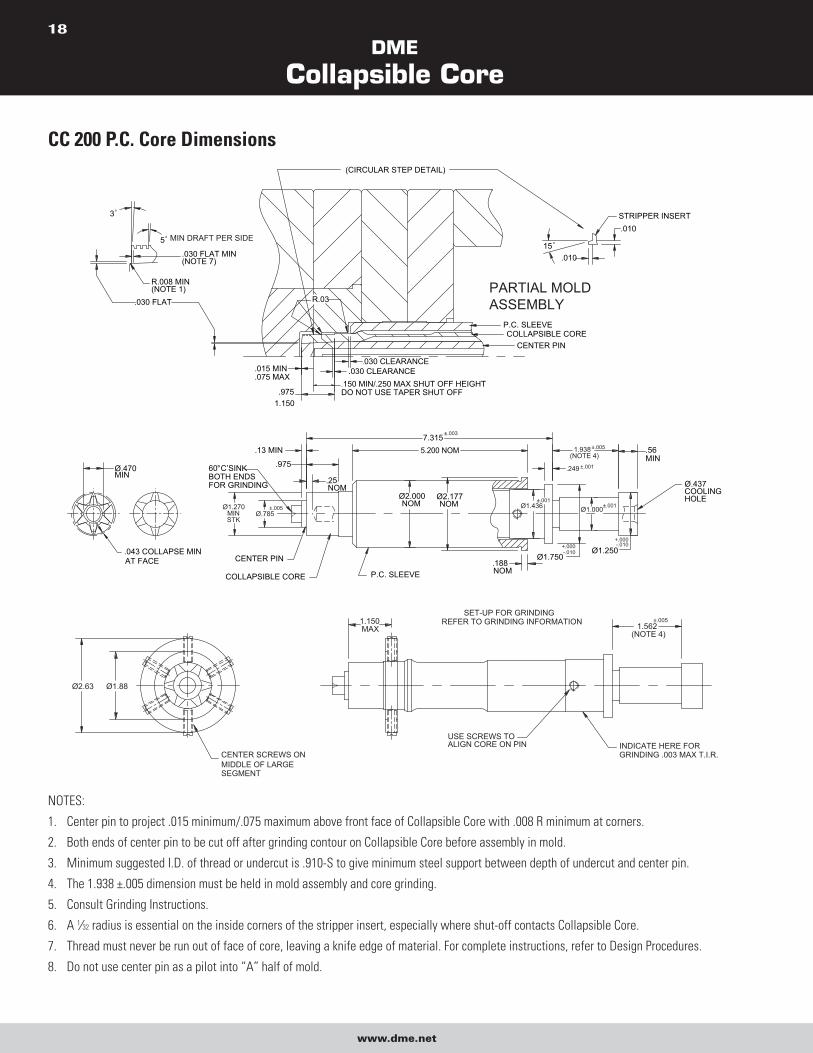
CC 200 P.C. Core Dimensions
.188
7.315
Ø.785
.13 MIN
.975
.25NOM
5.200 NOM
.249
Ø2.000NOM
Ø2.177NOM Ø1.436
Ø1.750
Ø1.000
Ø1.250
1.938(NOTE 4)
.56MIN
Ø.437COOLINGHOLE
CENTER PIN
COLLAPSIBLE CORE P.C. SLEEVE
60° C’SINKBOTH ENDSFOR GRINDING
Ø.470MIN
.043 COLLAPSE MINAT FACE
STK
Ø1.270MIN
NOM
±.003
±.005
±.001
±.001
+.000-.010
±.001
-.010+.000
±.005
.150 MIN/.250 MAX SHUT OFF HEIGHTDO NOT USE TAPER SHUT OFF
R.03
.9751.150
.010
.010
15
STRIPPER INSERT
5 MIN DRAFT PER SIDE
3
R.008 MIN(NOTE 1)
.030 FLAT MIN(NOTE 7)
.030 FLAT
.015 MIN
.075 MAX
.030 CLEARANCE.030 CLEARANCE
P.C. SLEEVECOLLAPSIBLE CORE
CENTER PIN
PARTIAL MOLDASSEMBLY
(CIRCULAR STEP DETAIL)
1.150MAX
Ø1.88Ø2.63
1.562(NOTE 4)
INDICATE HERE FORGRINDING .003 MAX T.I.R.
SET-UP FOR GRINDINGREFER TO GRINDING INFORMATION
USE SCREWS TOALIGN CORE ON PIN
CENTER SCREWS ONMIDDLE OF LARGESEGMENT
±.005
NOTES:
1. Center pin to project .015 minimum/.075 maximum above front face of Collapsible Core with .008 R minimum at corners.
2. Both ends of center pin to be cut off after grinding contour on Collapsible Core before assembly in mold.
3. Minimum suggested I.D. of thread or undercut is .910-S to give minimum steel support between depth of undercut and center pin.
4. The 1.938 ±.005 dimension must be held in mold assembly and core grinding.
5. Consult Grinding Instructions.
6. A 1⁄32 radius is essential on the inside corners of the stripper insert, especially where shut-off contacts Collapsible Core.
7. Thread must never be run out of face of core, leaving a knife edge of material. For complete instructions, refer to Design Procedures.
8. Do not use center pin as a pilot into “A” half of mold.
DME
Collapsible Core
www.dme.net
19
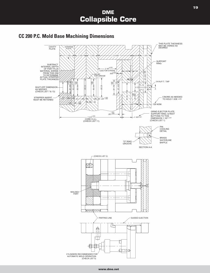
CC 200 P.C. Mold Base Machining Dimensions
.187
STRIPPER INSERTMUST BE RETAINED
1/4 N.P.T. TAP
Ø1.
255
±.001
±.005
BRASSWATERLINEBAFFLE
SECTION A-A
"O" RINGGROOVE
PINCOOLINGDETAIL
1.000
.800MIN.
Ø1.
406±.
007
Ø2.
016±.
005
Ø2.
004+.
003
-.000
Ø2.
03
.390
.375
.25
.56
Ø2.
004-.0
00+.
003
RELIEFFOR GREASE
Ø2.
25
.207+.003-.002 Ø
1.00
2+.
001
-.000
1.375.875
EJECTOR STROKE2.187
±.005
.625±.003
+.00
1-.0
00
+.00
5-.0
00Ø
1.75
5
Ø1.
438
-.000+.001
.251
Ø1.
06
1.938 ±.005 .126 NOM.
C-4.0001.3751.3751.753
PLATESTRIPPER
+.00
5-.0
00
1.187±.0017.315±.003
CORE O.A.L.
SUBTRACTINTERNAL DEPTH
OF PART PLUSMATERIAL SHRINK
FROM THIS DIM.TO DETERMINE
ACTUAL STRIPPERPLATE THICKNESS
PLATE
SHUT-OFF DIMENSIONAS NEEDED (CHECK LIST 7 & 13)
CAVITY
DIMENSION 1.187(CHECK LIST 1)
BUTTONS TO THISSUPPORT RING, & RESTGRIND EJECTOR PLATE,
C'BORE AS NEEDEDTO HOLD 1.938
SUPPORTRING
THIS PLATE THICKNESSMAY BE VARIED ASDESIRED
(CHECK LIST 11)
A
(CHECK LIST 2)
MOLDEDPART
CYLINDERS RECOMMENDED FORAUTOMATIC MOLD OPERATION
(CHECK LIST 5)
PARTING LINE GUIDED EJECTION
DME
Collapsible Core
www.dme.net
20
MOLD DESIGN CHECK LIST 1. Use guided ejector plates and a support ring around center pin. Ejector plate, support rings and rest buttons must be ground to 1.187 ±.001.
2. Use springs to assure first break at main parting line.
3. Return pins to end under stripper plate.
4. Ejector plate travel to specifications. Stamp dimension on edge of plate.
5. Secondary stripper plate actuation to begin only after full ejector plate travel. Stripper plate must return fully before ejector plate begins to
return (see Sequence Description).
6. Good venting is essential, preferable to outside of mold.
7. Clearance between core shut-off O.D. and stripper insert I.D. to be .0010/.0015 total. Measure core when installed in mold. No tapered
shut-off permitted. Avoid excessive shut-off length; .150/.250 is adequate.
8. Mounted core to be free to turn when in ejector plate assembly.
9. Center pin to be concentric with stripper bushing. Verify protrusion of pin through core and radius on tip of pin.
10. Positive collapse sleeve to travel freely through plates. Apply grease where indicated. Check for free movement when mold is at operating
temperature.
11. When face of Collapsible Core segments shut-off against cavity (some parts with through holes), all cores must be ground to the same
O.A.L. Normal tolerance of ±.003 is inadequate. Refer to Core Grinding Instructions. Clearance between end of core face and cavity to be
.0005 to .0010. Do not pre-load the core. Whenever the above condition exists, an early ejector plate return system must be used, or the
cores will be destroyed.
NOTE: This applies only when the core seals off against the cavity. When the pin is seating against the cavity exercise care to avoid
excessive pre-load of the pin. A .000 to .0015 interference is adequate.
12. Break all sharp corners.
13. The stripper shut-off diameter must be of the same diameter, or preferably, a larger diameter than any other diameter on the core.
NOTE: Due to the reduction in mold plate thicknesses as compared to the CC-200-PC Collapsible Core, no greater than a four-cavity
CC-250-PC Core mold is recommended.
DME
Collapsible Core
www.dme.net
21
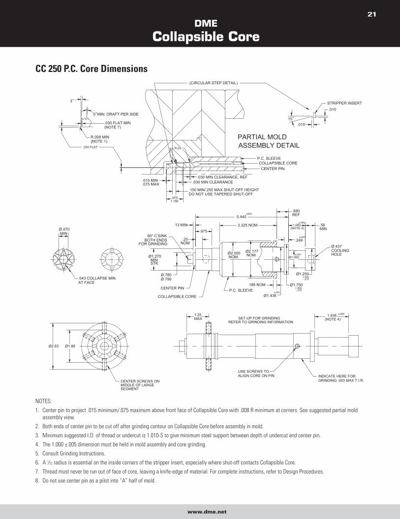
CC 250 P.C. Core Dimensions
P.C. SLEEVECOLLAPSIBLE CORECENTER PIN
.030 FLAT
.030 FLAT MIN(NOTE 7)
R.008 MIN(NOTE 1)
3°
.030 MIN CLEARANCE, REF.015 MIN.075 MAX
.9751.150
ASSEMBLY DETAILPARTIAL MOLD
.150 MIN/.250 MAX SHUT-OFF HEIGHTDO NOT USE TAPERED SHUT-OFF
(CIRCULAR STEP DETAIL)
R.03
5° MIN. DRAFT PER SIDE15°
.010
STRIPPER INSERT.010
.030 MIN CLEARANCE
.043 COLLAPSE MINAT FACE
Ø.470MIN
Ø1.750
.680REF
(NOTE 4)1.000
Ø1.000
.249
P.C. SLEEVECOLLAPSIBLE CORE
CENTER PIN
Ø2.177NOM.
Ø.780Ø.790
.188 NOM
.25
.975
5.440
.13 MIN
60° C’SINKBOTH ENDS
FOR GRINDING
Ø1.270MINSTK
NOM
3.325 NOM
Ø2.000NOM.
.56MIN
Ø.437COOLINGHOLE
Ø1.250
±.005
-.010+.000
Ø1.436±.001
.±003
+.000-.010
±.001
±.001
USE SCREWS TOALIGN CORE ON PIN INDICATE HERE FOR
GRINDING .003 MAX T.I.R.CENTER SCREWS ONMIDDLE OF LARGESEGMENT
Ø2.63 Ø1.88
REFER TO GRINDING INFORMATIONSET-UP FOR GRINDING
1.25MAX
1.938(NOTE 4)
±.005
NOTES:
1. Center pin to project .015 minimum/.075 maximum above front face of Collapsible Core with .008 R minimum at corners. See suggested partial mold
assembly view.
2. Both ends of center pin to be cut off after grinding contour on Collapsible Core before assembly in mold.
3. Minimum suggested I.D. of thread or undercut is 1.010-S to give minimum steel support between depth of undercut and center pin.
4. The 1.000 ±.005 dimension must be held in mold assembly and core grinding.
5. Consult Grinding Instructions.
6. A 1⁄32 radius is essential on the inside corners of the stripper insert, especially where shut-off contacts Collapsible Core.
7. Thread must never be run out of face of core, leaving a knife-edge of material. For complete instructions, refer to Design Procedures.
8. Do not use center pin as a pilot into “A” half of mold.
DME
Collapsible Core
www.dme.net
22
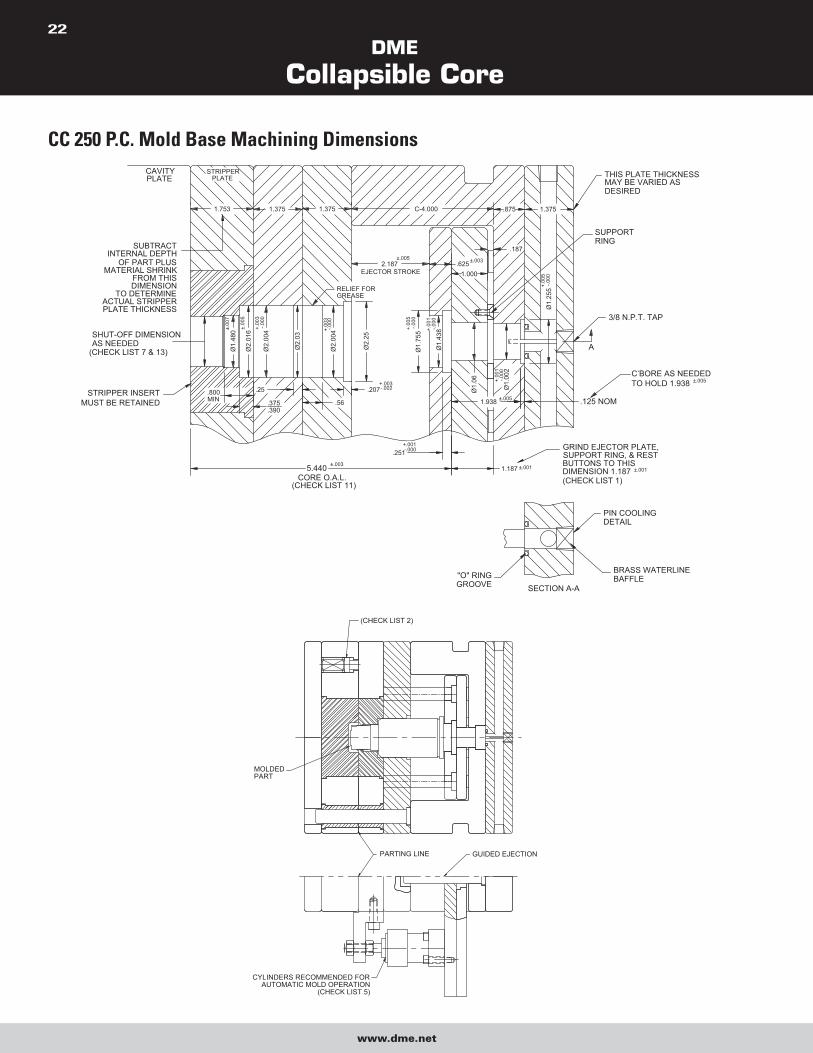
CC 250 P.C. Mold Base Machining Dimensions
STRIPPER INSERTMUST BE RETAINED .125 NOM1.938
.251
.56.800MIN
SECTION A-A
SUPPORT RING, & RESTGRIND EJECTOR PLATE,
DIMENSION 1.187BUTTONS TO THIS
(CHECK LIST 1)
±.003
CORE O.A.L.(CHECK LIST 11)
5.440
.375
.390
"O" RINGGROOVE
-.000+.001
±.0011.187
BRASS WATERLINEBAFFLE
PIN COOLINGDETAIL
±.001
-.000
Ø1.
255
1.375.875C-4.0001.3751.3751.753
.207
RELIEF FOR GREASE
Ø2.
004±.
007
Ø1.
480SHUT-OFF DIMENSION
AS NEEDED (CHECK LIST 7 & 13) Ø
2.03
Ø2.
004
Ø2.
016
.25
±.00
5
-.000
+.00
3
-.000
+.00
3
SUBTRACTINTERNAL DEPTH
OF PART PLUSMATERIAL SHRINK
FROM THIS DIMENSION
TO DETERMINEACTUAL STRIPPERPLATE THICKNESS
Ø2.
25
Ø1.
438
Ø1.
755
-.002+.003
-.000
+.00
1
-.000
+.00
5
Ø1.
002
Ø1.
06 -.000
+.00
1
±.005
EJECTOR STROKE2.187
±.005
1.000.625±.003
+.00
5
.187
STRIPPERPLATEPLATE
CAVITY THIS PLATE THICKNESSMAY BE VARIED ASDESIRED
3/8 N.P.T. TAP
C’BORE AS NEEDEDTO HOLD 1.938 ±.005
SUPPORTRING
A
PARTING LINE GUIDED EJECTION
MOLDEDPART
(CHECK LIST 2)
CYLINDERS RECOMMENDED FORAUTOMATIC MOLD OPERATION
(CHECK LIST 5)

DME
Collapsible Core
www.dme.net
23
MOLD DESIGN CHECK LIST 1. Use guided ejector plates and a support ring around center pin. Ejector plate, support rings and rest buttons must be ground to .625 ±.001.
2. Use springs to assure first break at main parting line.
3. Return pins to end under stripper plate.
4. Ejector plate travel to specifications. Stamp dimension on edge of plate.
5. Secondary stripper plate actuation to begin only after full ejector plate travel. Stripper plate must return fully before ejector plate begins to
return (see Sequence Description).
6. Good venting is essential, preferably to outside of mold.
7. Clearance between core shut-off O.D. and stripper insert I.D. to be .0010/.0015 total. Measure core when installed in mold. No tapered
shut-off permitted. Avoid excessive shut-off length; .150/.250 is adequate.
8. Mounted core to be free to turn when in ejector plate assembly.
9. Center pin to be concentric with stripper bushing. Verify protrusion of pin through core and radius on tip of pin.
10. Positive collapse sleeve to travel freely through plates. Apply grease where indicated. Check for free movement when mold is at operating
temperature.
11. When face of Collapsible Core segments shut-off against cavity (some parts with through holes), all cores must be ground to the same
O.A.L. Normal tolerance of ±.003 is inadequate. Refer to Core Grinding Instructions. Clearance between end of core face and cavity to be
.0005 to .0010. Do not pre-load the core. Whenever the above condition exists, an early ejector plate return system must be used, or the
cores will be destroyed.
NOTE: This applies only when the core seals off against the cavity. When the pin is seating against the cavity exercise care to avoid
excessive pre-load of the pin. A .000 to .0015 interference is adequate.
12. Break all sharp corners.
13. The stripper shut-off diameter must be of the same diameter, or preferably, a larger diameter than any other diameter on the core.
NOTE: Due to the reduction in mold plate thicknesses as compared to the CC-200-PC Collapsible Core, no greater than a four-cavity
CC-250-PC Core mold is recommended.
DME
Collapsible Core
www.dme.net
24
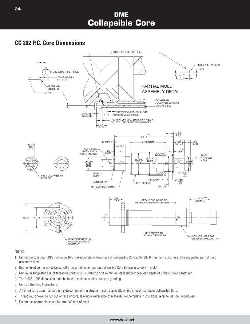
CC 202 P.C. Core Dimensions
P.C. SLEEVECOLLAPSIBLE CORECENTER PIN
.030 FLAT
.030 FLAT MIN(NOTE 7)
R.008 MIN(NOTE 1)
3°
.030 MIN CLEARANCE, REF.015 MIN.075 MAX
.9751.150
ASSEMBLY DETAILPARTIAL MOLD
.150 MIN/.250 MAX SHUT-OFF HEIGHTDO NOT USE TAPERED SHUT-OFF
(CIRCULAR STEP DETAIL)
R.03
5° MIN. DRAFT PER SIDE15°
.010
STRIPPER INSERT.010
.030 MIN CLEARANCE
.055 COLLAPSE MINAT FACE
Ø.470MIN
Ø1.750
.680REF
(NOTE 4)1.938
Ø1.000
.249
P.C. SLEEVECOLLAPSIBLE CORE
CENTER PIN
Ø2.177NOM.
Ø.880Ø.890
.188 NOM
.25
.975
7.315
.13 MIN
60° C’SINKBOTH ENDS
FOR GRINDING
Ø1.390MINSTK
NOM
5.200 NOM
Ø2.000NOM.
.56MIN
Ø.500COOLINGHOLE
Ø1.250
±.005
-.010+.000
Ø1.436±.001
.±003
+.000-.010
±.001
±.001
USE SCREWS TOALIGN CORE ON PIN INDICATE HERE FOR
GRINDING .003 MAX T.I.R.CENTER SCREWS ONMIDDLE OF LARGESEGMENT
Ø2.63 Ø1.88
REFER TO GRINDING INFORMATIONSET-UP FOR GRINDING
1.25MAX
1.938(NOTE 4)
±.005
NOTES:
1. Center pin to project .015 minimum/.075 maximum above front face of Collapsible Core with .008 R minimum at corners. See suggested partial mold
assembly view.
2. Both ends of center pin to be cut off after grinding contour on Collapsible Core before assembly in mold.
3. Minimum suggested I.D. of thread or undercut is 1.010-S to give minimum steel support between depth of undercut and center pin.
4. The 1.938 ±.005 dimension must be held in mold assembly and core grinding.
5. Consult Grinding Instructions.
6. A 1⁄32 radius is essential on the inside corners of the stripper insert, especially where shut-off contacts Collapsible Core.
7. Thread must never be run out of face of core, leaving a knife-edge of material. For complete instructions, refer to Design Procedures.
8. Do not use center pin as a pilot into “A” half of mold.
DME
Collapsible Core
www.dme.net
25
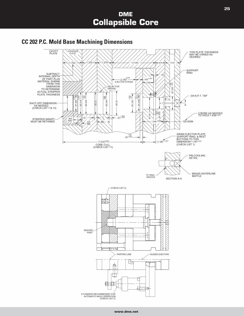
CC 202 P.C. Mold Base Machining Dimensions
STRIPPER INSERTMUST BE RETAINED .125 NOM1.938
.251
.56.800MIN
SECTION A-A
SUPPORT RING, & RESTGRIND EJECTOR PLATE,
DIMENSION 1.187BUTTONS TO THIS
(CHECK LIST 1) ±.003
CORE O.A.L.(CHECK LIST 11)
7.315
.375
.390
"O" RINGGROOVE
-.000+.001
±.0011.187
BRASS WATERLINEBAFFLE
PIN COOLINGDETAIL
±.001
-.000
Ø1.
255
1.375.875C-4.0001.3751.3751.753
.207
RELIEF FOR GREASE
Ø2.
004±.
007
Ø1.
480
SHUT-OFF DIMENSIONAS NEEDED
(CHECK LIST 7 & 13)
Ø2.
03
Ø2.
004
Ø2.
016
.25
±.00
5
-.000
+.00
3
-.000
+.00
3
SUBTRACTINTERNAL DEPTH
OF PART PLUSMATERIAL SHRINK
FROM THIS DIMENSION
TO DETERMINEACTUAL STRIPPERPLATE THICKNESS
Ø2.
25
Ø1.
438
Ø1.
755
-.002+.003
-.000
+.00
1
-.000
+.00
5
Ø1.
002
Ø1.
06 -.000
+.00
1
±.005
EJECTOR STROKE2.187
±.005
1.000.625±.003
+.00
5
.187
STRIPPERPLATEPLATE
CAVITY THIS PLATE THICKNESSMAY BE VARIED ASDESIRED
3/8 N.P.T. TAP
C’BORE AS NEEDEDTO HOLD 1.938 ±.005
SUPPORTRING
A
(CHECK LIST 2)
GUIDED EJECTIONPARTING LINE
MOLDEDPART
CYLINDERS RECOMMENDED FORAUTOMATIC MOLD OPERATION
(CHECK LIST 5)
DME
Collapsible Core
www.dme.net
26
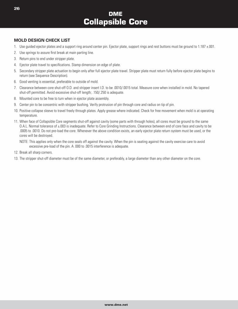
MOLD DESIGN CHECK LIST 1. Use guided ejector plates and a support ring around center pin. Ejector plate, support rings and rest buttons must be ground to 1.187 ±.001.
2. Use springs to assure first break at main parting line.
3. Return pins to end under stripper plate.
4. Ejector plate travel to specifications. Stamp dimension on edge of plate.
5. Secondary stripper plate actuation to begin only after full ejector plate travel. Stripper plate must return fully before ejector plate begins to
return (see Sequence Description).
6. Good venting is essential, preferable to outside of mold.
7. Clearance between core shut-off O.D. and stripper insert I.D. to be .0010/.0015 total. Measure core when installed in mold. No tapered
shut-off permitted. Avoid excessive shut-off length; .150/.250 is adequate.
8. Mounted core to be free to turn when in ejector plate assembly.
9. Center pin to be concentric with stripper bushing. Verify protrusion of pin through core and radius on tip of pin.
10. Positive collapse sleeve to travel freely through plates. Apply grease where indicated. Check for free movement when mold is at operating
temperature.
11. When face of Collapsible Core segments shut-off against cavity (some parts with through holes), all cores must be ground to the same
O.A.L. Normal tolerance of ±.003 is inadequate. Refer to Core Grinding Instructions. Clearance between end of core face and cavity to be
.0005 to .0010. Do not pre-load the core. Whenever the above condition exists, an early ejector plate return system must be used, or the
cores will be destroyed.
NOTE: This applies only when the core seals off against the cavity. When the pin is seating against the cavity exercise care to avoid
excessive pre-load of the pin. A .000 to .0015 interference is adequate.
12. Break all sharp corners.
13. The stripper shut-off diameter must be of the same diameter, or preferably, a large diameter than any other diameter on the core.
DME
Collapsible Core
www.dme.net
27
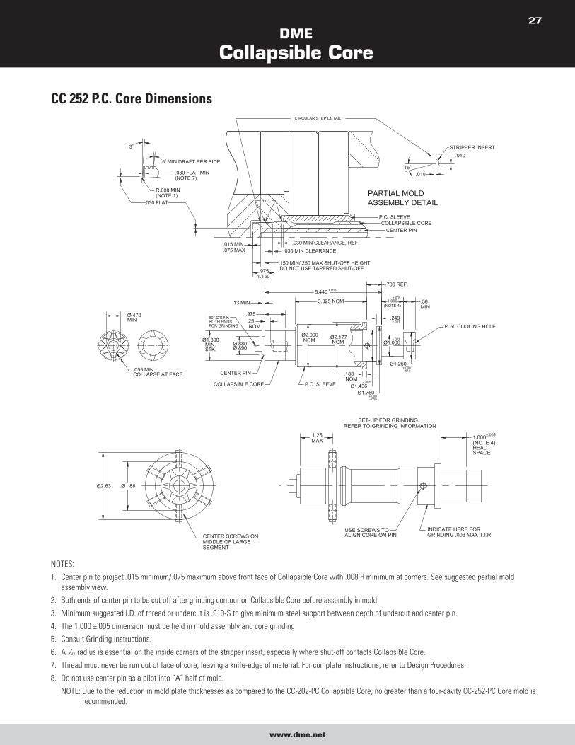
CC 252 P.C. Core Dimensions
.055 MINCOLLAPSE AT FACE
Ø.470MIN
.700 REF.
1.000
Ø1.250
COLLAPSIBLE CORE
CENTER PIN
Ø1.750
Ø2.177NOM
Ø2.000NOM
P.C. SLEEVE
.188
Ø1.436
.975
5.440
.13 MIN.
60° C’SINKBOTH ENDSFOR GRINDING
Ø1.390MIN.STK.
.25
Ø.880Ø.890
NOM
3.325 NOM
Ø1.000
.249
(NOTE 4).56MIN
Ø.50 COOLING HOLE
+.000-.010
-.010+.000
±.001NOM
±.001
±.001
±.003
±.005
CENTER PINCOLLAPSIBLE CORE
P.C. SLEEVE
.030 FLAT
.030 FLAT MIN(NOTE 7)
R.008 MIN(NOTE 1)
3°
.030 MIN CLEARANCE, REF..015 MIN.075 MAX
.9751.150
.150 MIN/.250 MAX SHUT-OFF HEIGHTDO NOT USE TAPERED SHUT-OFF
PARTIAL MOLDASSEMBLY DETAIL
(CIRCULAR STEP DETAIL)
R.03
5° MIN DRAFT PER SIDE15°
.010
.010
STRIPPER INSERT
.030 MIN CLEARANCE
INDICATE HERE FORGRINDING .003 MAX T.I.R.CENTER SCREWS ON
MIDDLE OF LARGESEGMENT
USE SCREWS TOALIGN CORE ON PIN
Ø2.63 Ø1.88
1.000(NOTE 4)HEADSPACE
1.25MAX
REFER TO GRINDING INFORMATIONSET-UP FOR GRINDING
±.005
NOTES:
1. Center pin to project .015 minimum/.075 maximum above front face of Collapsible Core with .008 R minimum at corners. See suggested partial mold
assembly view.
2. Both ends of center pin to be cut off after grinding contour on Collapsible Core before assembly in mold.
3. Minimum suggested I.D. of thread or undercut is .910-S to give minimum steel support between depth of undercut and center pin.
4. The 1.000 ±.005 dimension must be held in mold assembly and core grinding
5. Consult Grinding Instructions.
6. A 1⁄32 radius is essential on the inside corners of the stripper insert, especially where shut-off contacts Collapsible Core.
7. Thread must never be run out of face of core, leaving a knife-edge of material. For complete instructions, refer to Design Procedures.
8. Do not use center pin as a pilot into “A” half of mold.
NOTE: Due to the reduction in mold plate thicknesses as compared to the CC-202-PC Collapsible Core, no greater than a four-cavity CC-252-PC Core mold is
recommended.
DME
Collapsible Core
www.dme.net
28
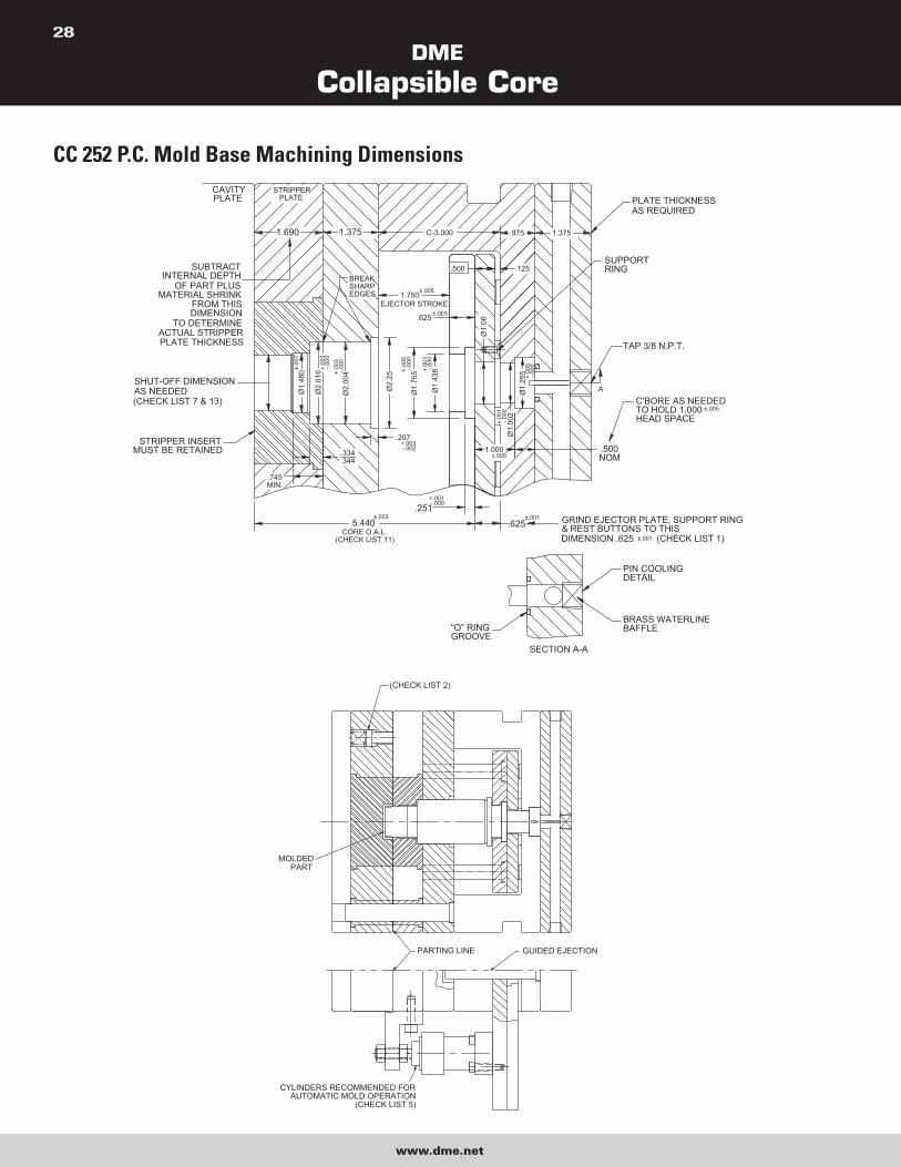
CC 252 P.C. Mold Base Machining Dimensions
“O” RINGGROOVE
BRASS WATERLINEBAFFLE
SECTION A-A
GRIND EJECTOR PLATE, SUPPORT RING& REST BUTTONS TO THISDIMENSION .625 (CHECK LIST 1)
PIN COOLINGDETAIL
±.001
1.000
Ø1.
002
.125
.875
.625
EJECTOR STROKE
SUBTRACTINTERNAL DEPTH
OF PART PLUSMATERIAL SHRINK
FROM THIS DIMENSION
TO DETERMINEACTUAL STRIPPERPLATE THICKNESS
.745MIN.
5.440
STRIPPER INSERTMUST BE RETAINED
SHUT-OFF DIMENSIONAS NEEDED (CHECK LIST 7 & 13)
Ø2.
004
-.000
+.00
1
.251
Ø2.
25
-.002+.003
.207
CORE O.A.L.(CHECK LIST 11)
±.003
.334
.344
+.001-.000
±.005
+.00
3-.0
00
-.000
±.00
7
+.00
3
Ø1.
480
Ø2.
016 +.
001
-.000
+.00
5
-.000
Ø1.
755
Ø1.
06
Ø1.
438
.625 ±.003
STRIPPER
1.690
PLATECAVITYPLATE
C-3.000
1.750
BREAKSHARPEDGES
1.375
.500
±.005
.500NOM
C'BORE AS NEEDEDTO HOLD 1.000HEAD SPACE
±.001
TAP 3/8 N.P.T.
Ø1.
255 -.0
00+.
005
±.005
SUPPORTRING
PLATE THICKNESSAS REQUIRED
1.375
A
(CHECK LIST 2)
MOLDEDPART
PARTING LINE GUIDED EJECTION
CYLINDERS RECOMMENDED FORAUTOMATIC MOLD OPERATION
(CHECK LIST 5)

DME
Collapsible Core
www.dme.net
29
MOLD DESIGN CHECK LIST 1. Use guided ejector plates and a support ring around center pin. Ejector plate, support rings and rest buttons must be ground to .625 ±.001.
2. Use springs to assure first break at main parting line.
3. Return pins to end under stripper plate.
4. Ejector plate travel to specifications. Stamp dimension on edge of plate.
5. Secondary stripper plate actuation to begin only after full ejector plate travel. Stripper plate must return fully before ejector plate begins to
return (see Sequence Description).
6. Good venting is essential, preferable to outside of mold.
7. Clearance between core shut-off O.D. and stripper insert I.D. to be .0010/.0015 total. Measure core when installed in mold. No tapered
shut-off permitted. Avoid excessive shut-off length; .150/.250 is adequate.
8. Mounted core to be free to turn when in ejector plate assembly.
9. Center pin to be concentric with stripper bushing. Verify protrusion of pin through core and radius on tip of pin.
10. Positive collapse sleeve to travel freely through plates. Apply grease where indicated. Check for free movement when mold is at operating
temperature.
11. When face of Collapsible Core segments shut-off against cavity (some parts with through holes), all cores must be ground to the same
O.A.L. Normal tolerance of ±.003 is inadequate. Refer to Core Grinding Instructions. Clearance between end of core face and cavity to be
.0005 to .0010. Do not pre-load the core. Whenever the above condition exists, an early ejector plate return system must be used, or the
cores will be destroyed.
NOTE: This applies only when the core seals off against the cavity. When the pin is seating against the cavity exercise care to avoid
excessive pre-load of the pin. A .000 to .0015 interference is adequate.
12. Break all sharp corners.
13. The stripper shut-off diameter must be of the same diameter, or preferably, a large diameter than any other diameter on the core.
NOTE: Due to the reduction in mold plate thicknesses as compared to the CC-202-PC Collapsible Core, no greater than a four-cavity
CC-252-PC Core mold is recommended.
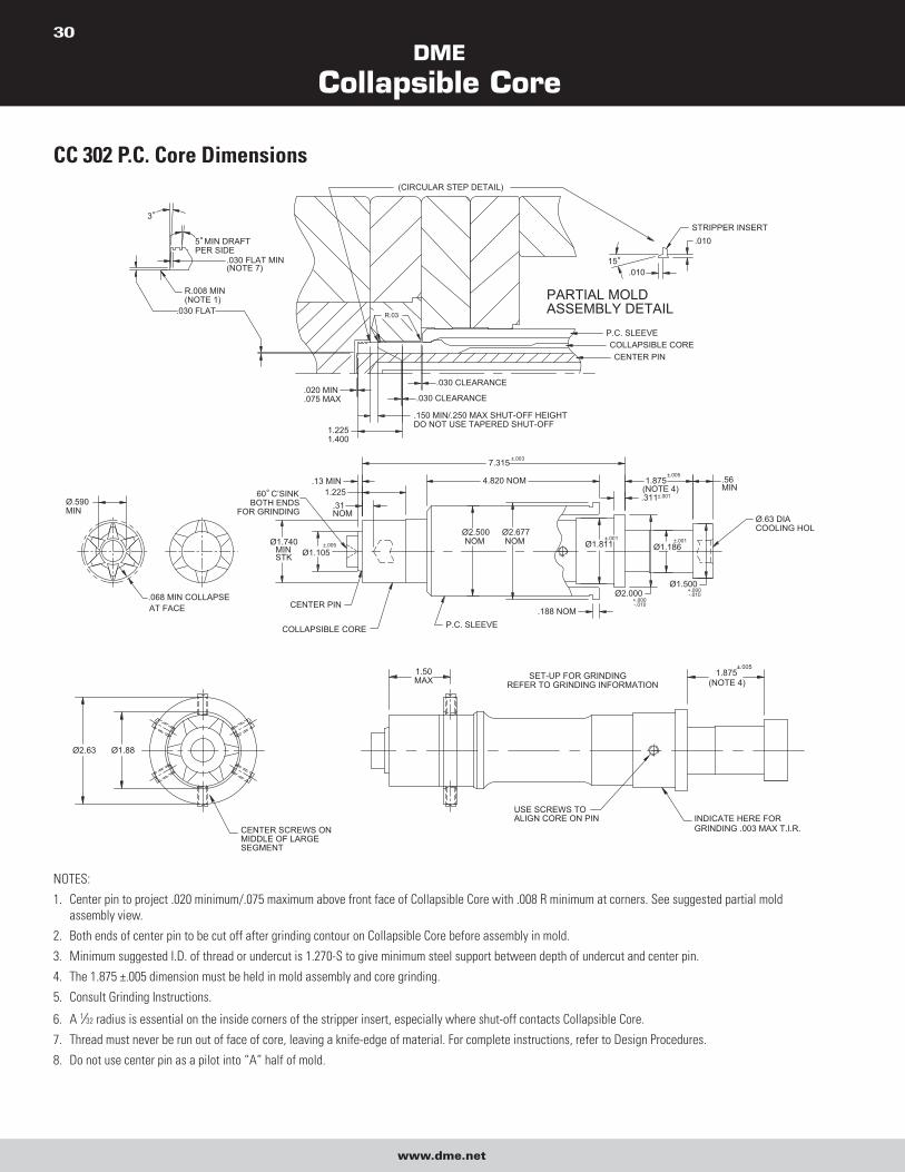
DME
Collapsible Core
www.dme.net
30
CC 302 P.C. Core Dimensions
1.875
Ø2.000
.311Ø.590MIN
.068 MIN COLLAPSEAT FACE
60° C’SINKBOTH ENDS
FOR GRINDING
Ø1.811Ø2.677NOM
Ø2.500NOM
.31NOM
Ø1.105
COLLAPSIBLE CORE
CENTER PIN.188 NOM
P.C. SLEEVE
4.820 NOM
7.315
1.225.13 MIN
Ø.63 DIACOOLING HOL
Ø1.500
Ø1.186
.56MIN(NOTE 4)
±.005
STK
Ø1.740MIN
-.010+.000
±.001
±.003
±.001
+.000-.010
±.005
±.001
.01015°
P.C. SLEEVE
CENTER PINCOLLAPSIBLE CORE
.030 CLEARANCE.020 MIN.075 MAX
1.2251.400
.030 CLEARANCE
.150 MIN/.250 MAX SHUT-OFF HEIGHTDO NOT USE TAPERED SHUT-OFF
PARTIAL MOLDASSEMBLY DETAIL
5° MIN DRAFTPER SIDE
.030 FLAT MIN(NOTE 7)
R.008 MIN(NOTE 1)
.030 FLAT
3°
(CIRCULAR STEP DETAIL)
R.03
STRIPPER INSERT.010
1.875(NOTE 4)
INDICATE HERE FORGRINDING .003 MAX T.I.R.
REFER TO GRINDING INFORMATION1.50MAX
Ø1.88Ø2.63
CENTER SCREWS ONMIDDLE OF LARGESEGMENT
USE SCREWS TOALIGN CORE ON PIN
SET-UP FOR GRINDING±.005
NOTES:
1. Center pin to project .020 minimum/.075 maximum above front face of Collapsible Core with .008 R minimum at corners. See suggested partial mold
assembly view.
2. Both ends of center pin to be cut off after grinding contour on Collapsible Core before assembly in mold.
3. Minimum suggested I.D. of thread or undercut is 1.270-S to give minimum steel support between depth of undercut and center pin.
4. The 1.875 ±.005 dimension must be held in mold assembly and core grinding.
5. Consult Grinding Instructions.
6. A 1⁄32 radius is essential on the inside corners of the stripper insert, especially where shut-off contacts Collapsible Core.
7. Thread must never be run out of face of core, leaving a knife-edge of material. For complete instructions, refer to Design Procedures.
8. Do not use center pin as a pilot into “A” half of mold.
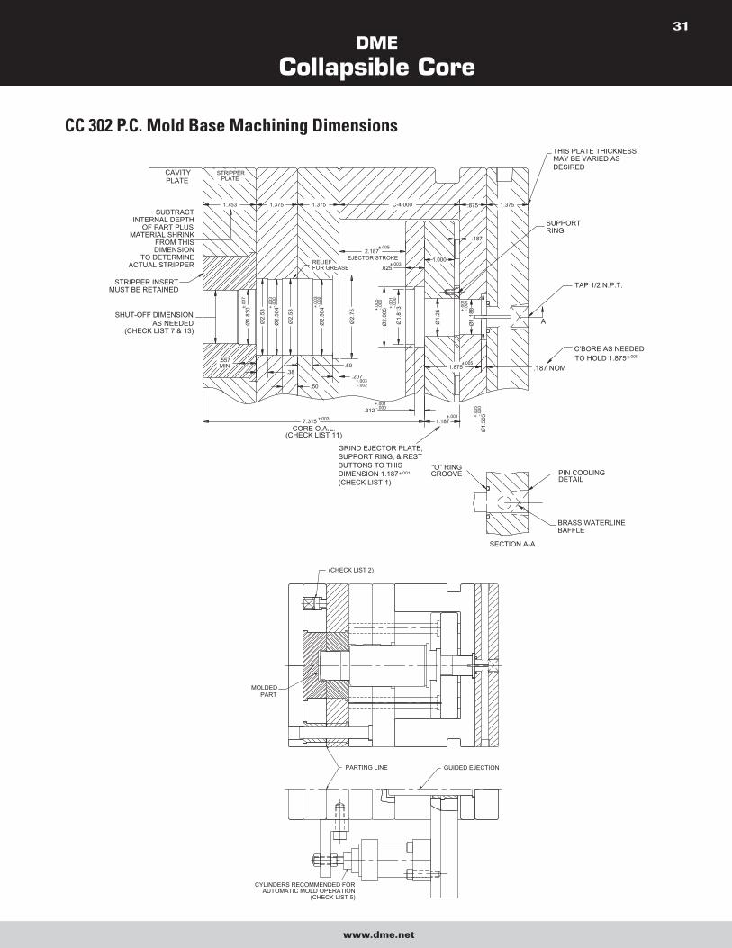
DME
Collapsible Core
www.dme.net
31
CC 302 P.C. Mold Base Machining Dimensions
TAP 1/2 N.P.T.
BRASS WATERLINEBAFFLE
THIS PLATE THICKNESSMAY BE VARIED ASDESIRED
C’BORE AS NEEDEDTO HOLD 1.875
SECTION A-A
EJECTOR STROKE 1.000
SUBTRACTINTERNAL DEPTH
OF PART PLUSMATERIAL SHRINK
FROM THIS DIMENSION
TO DETERMINEACTUAL STRIPPER
.38
.557MIN
7.315
Ø1.
830
STRIPPER INSERTMUST BE RETAINED
SHUT-OFF DIMENSIONAS NEEDED
(CHECK LIST 7 & 13)
±.00
7
.312
.50
Ø1.
505±.003
CORE O.A.L.(CHECK LIST 11)
-.000+.001
“O” RINGGROOVE PIN COOLING
DETAIL
1.187±.001 -.0
00+.
005
1.875
Ø1.
25
Ø2.
504
Ø2.
53
Ø2.
504
Ø2.
53
Ø1.
813
Ø2.
005
Ø2.
75
.207
.50
-.002+.003
RELIEFFOR GREASE
-.000
+.00
3
+.00
3-.0
00
-.000
+.00
5
+.00
1-.0
00
.625±.003
.187 NOM
Ø1.
188
±.005
-.000
+.00
1
1.753
PLATECAVITY
PLATESTRIPPER
C-4.000
2.187
1.375 1.375
±.005
1.375
.187
.875
SUPPORTRING
±.005
A
GRIND EJECTOR PLATE,SUPPORT RING, & RESTBUTTONS TO THISDIMENSION 1.187(CHECK LIST 1)
±.001
PARTING LINE
CYLINDERS RECOMMENDED FORAUTOMATIC MOLD OPERATION
(CHECK LIST 5)
GUIDED EJECTION
(CHECK LIST 2)
MOLDEDPART
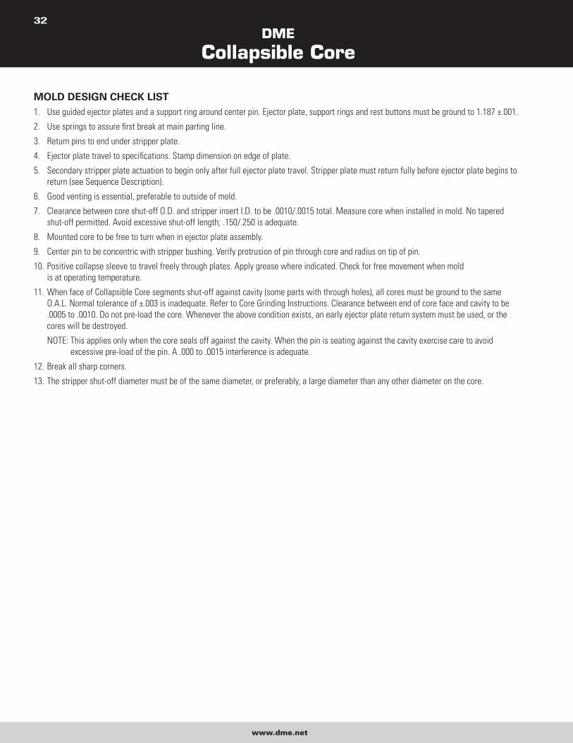
DME
Collapsible Core
www.dme.net
32
MOLD DESIGN CHECK LIST 1. Use guided ejector plates and a support ring around center pin. Ejector plate, support rings and rest buttons must be ground to 1.187 ±.001.
2. Use springs to assure first break at main parting line.
3. Return pins to end under stripper plate.
4. Ejector plate travel to specifications. Stamp dimension on edge of plate.
5. Secondary stripper plate actuation to begin only after full ejector plate travel. Stripper plate must return fully before ejector plate begins to
return (see Sequence Description).
6. Good venting is essential, preferable to outside of mold.
7. Clearance between core shut-off O.D. and stripper insert I.D. to be .0010/.0015 total. Measure core when installed in mold. No tapered
shut-off permitted. Avoid excessive shut-off length; .150/.250 is adequate.
8. Mounted core to be free to turn when in ejector plate assembly.
9. Center pin to be concentric with stripper bushing. Verify protrusion of pin through core and radius on tip of pin.
10. Positive collapse sleeve to travel freely through plates. Apply grease where indicated. Check for free movement when mold
is at operating temperature.
11. When face of Collapsible Core segments shut-off against cavity (some parts with through holes), all cores must be ground to the same
O.A.L. Normal tolerance of ±.003 is inadequate. Refer to Core Grinding Instructions. Clearance between end of core face and cavity to be
.0005 to .0010. Do not pre-load the core. Whenever the above condition exists, an early ejector plate return system must be used, or the
cores will be destroyed.
NOTE: This applies only when the core seals off against the cavity. When the pin is seating against the cavity exercise care to avoid
excessive pre-load of the pin. A .000 to .0015 interference is adequate.
12. Break all sharp corners.
13. The stripper shut-off diameter must be of the same diameter, or preferably, a large diameter than any other diameter on the core.
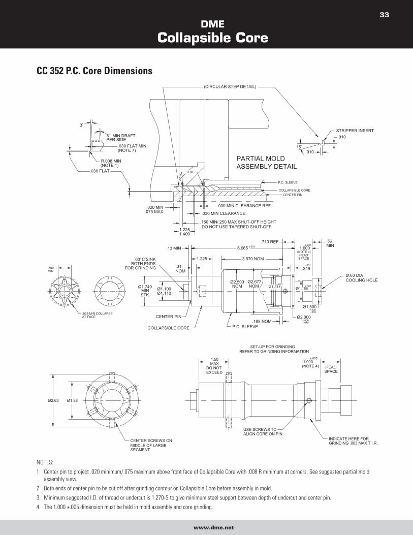
DME
Collapsible Core
www.dme.net
33
CC 352 P.C. Core Dimensions
60° C’SINKBOTH ENDS
FOR GRINDING
Ø1.740MINSTK
.590MIN
.068 MIN COLLAPSEAT FACE
Ø.63 DIACOOLING HOLE
Ø1.500
Ø1.811Ø2.677NOM
Ø2.500NOM
.31
.13 MIN
P.C. SLEEVE
CENTER PIN
Ø1.100Ø1.110
COLLAPSIBLE CORE.188 NOM
Ø2.000
Ø1.186
3.570 NOM
6.065
NOM
1.225
.710 REF
.249
.56MIN1.000
(NOTE 4)HEAD
SPACE
±.001
-.010+.000
+.000-.010
±.001
±.003
±.001
±.005
P.C. SLEEVE
CENTER PINCOLLAPSIBLE CORE
5° MIN DRAFTPER SIDE
.030 FLAT MIN(NOTE 7)
R.008 MIN(NOTE 1)
.030 FLAT
3°
R.03
(CIRCULAR STEP DETAIL)
.150 MIN/.250 MAX SHUT-OFF HEIGHTDO NOT USE TAPERED SHUT-OFF
.030 MIN CLEARANCE REF.
1.2251.400
.020 MIN.075 MAX
PARTIAL MOLDASSEMBLY DETAIL
15°
.010
.010STRIPPER INSERT
.030 MIN CLEARANCE
Ø1.88Ø2.63
CENTER SCREWS ONMIDDLE OF LARGESEGMENT
INDICATE HERE FORGRINDING .003 MAX T.I.R.
USE SCREWS TOALIGN CORE ON PIN
REFER TO GRINDING INFORMATIONSET-UP FOR GRINDING
1.50MAX
DO NOTEXCEED
1.000(NOTE 4) HEAD
SPACE
±.005
NOTES:
1. Center pin to project .020 minimum/.075 maximum above front face of Collapsible Core with .008 R minimum at corners. See suggested partial mold
assembly view.
2. Both ends of center pin to be cut off after grinding contour on Collapsible Core before assembly in mold.
3. Minimum suggested I.D. of thread or undercut is 1.270-S to give minimum steel support between depth of undercut and center pin.
4. The 1.000 ±.005 dimension must be held in mold assembly and core grinding.
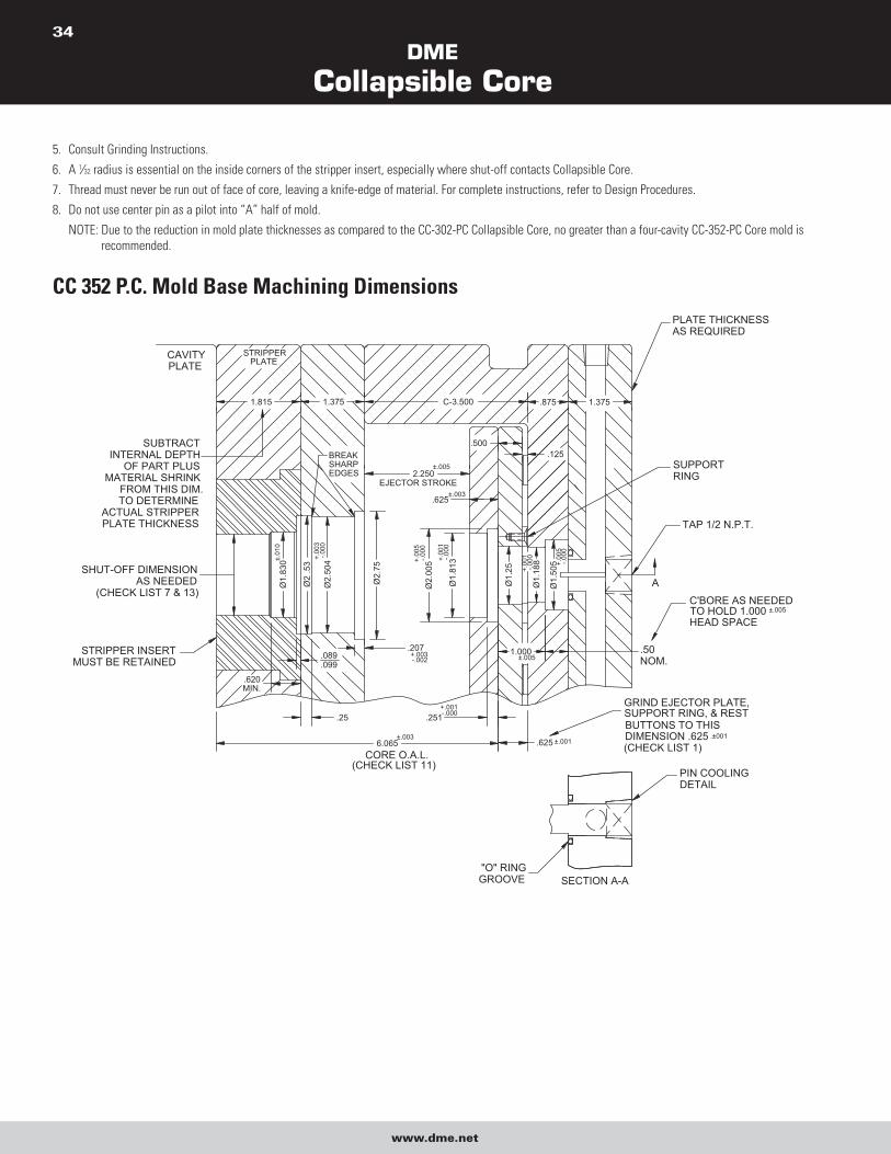
DME
Collapsible Core
www.dme.net
34
5. Consult Grinding Instructions.
6. A 1⁄32 radius is essential on the inside corners of the stripper insert, especially where shut-off contacts Collapsible Core.
7. Thread must never be run out of face of core, leaving a knife-edge of material. For complete instructions, refer to Design Procedures.
8. Do not use center pin as a pilot into “A” half of mold.
NOTE: Due to the reduction in mold plate thicknesses as compared to the CC-302-PC Collapsible Core, no greater than a four-cavity CC-352-PC Core mold is
recommended.
CC 352 P.C. Mold Base Machining Dimensions
.251.25
.620MIN.
6.065
"O" RINGGROOVE SECTION A-A
CORE O.A.L.(CHECK LIST 11)
±.003
+.001-.000
.625 ±.001
PIN COOLINGDETAIL
BUTTONS TO THISSUPPORT RING, & RESTGRIND EJECTOR PLATE,
DIMENSION .625(CHECK LIST 1)
.±001
1.375
.50NOM.
SUBTRACTINTERNAL DEPTH
OF PART PLUSMATERIAL SHRINK
FROM THIS DIM.TO DETERMINE
ACTUAL STRIPPERPLATE THICKNESS
C-3.500
BREAKSHARPEDGES
.207
Ø1.
830
Ø2.
504
Ø2
.53
STRIPPER INSERTMUST BE RETAINED .099
.089
SHUT-OFF DIMENSIONAS NEEDED
(CHECK LIST 7 & 13)
±.01
0
+.00
3-.0
00
-.000
+.00
5
Ø1.
188
Ø1.
25 -.000
+.00
1
Ø1.
813
Ø2.
005
Ø2.
75
Ø1.
505
-.002+.003 1.000
±.005
.500
+.00
5
+.00
1
-.000
-.000
±.003.625
2.250EJECTOR STROKE
±.005
.125
1.375
PLATECAVITY
PLATE
1.815
STRIPPER
.875
TAP 1/2 N.P.T.
C'BORE AS NEEDEDTO HOLD 1.000HEAD SPACE
SUPPORTRING
PLATE THICKNESSAS REQUIRED
±.005
A
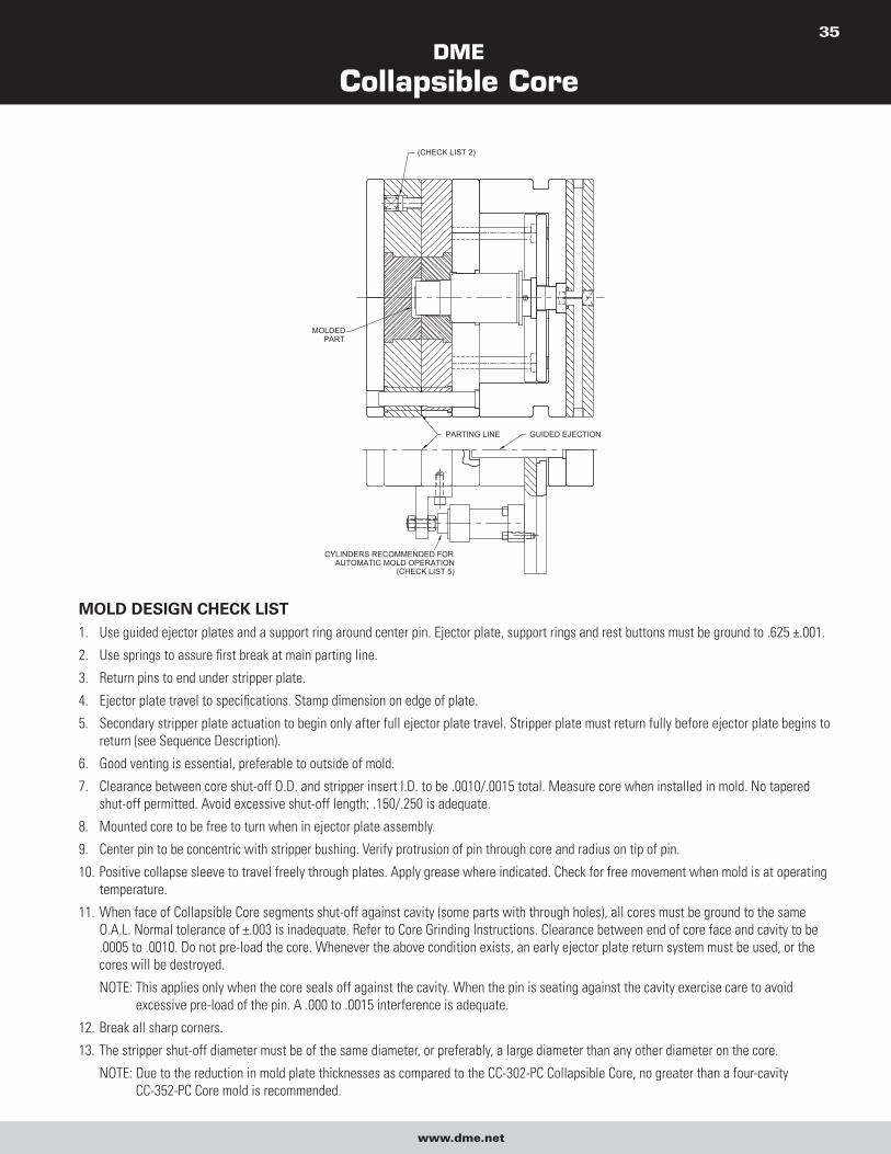
DME
Collapsible Core
www.dme.net
35
GUIDED EJECTIONPARTING LINE
(CHECK LIST 2)
MOLDEDPART
CYLINDERS RECOMMENDED FORAUTOMATIC MOLD OPERATION
(CHECK LIST 5)
MOLD DESIGN CHECK LIST 1. Use guided ejector plates and a support ring around center pin. Ejector plate, support rings and rest buttons must be ground to .625 ±.001.
2. Use springs to assure first break at main parting line.
3. Return pins to end under stripper plate.
4. Ejector plate travel to specifications. Stamp dimension on edge of plate.
5. Secondary stripper plate actuation to begin only after full ejector plate travel. Stripper plate must return fully before ejector plate begins to
return (see Sequence Description).
6. Good venting is essential, preferable to outside of mold.
7. Clearance between core shut-off O.D. and stripper insert I.D. to be .0010/.0015 total. Measure core when installed in mold. No tapered
shut-off permitted. Avoid excessive shut-off length; .150/.250 is adequate.
8. Mounted core to be free to turn when in ejector plate assembly.
9. Center pin to be concentric with stripper bushing. Verify protrusion of pin through core and radius on tip of pin.
10. Positive collapse sleeve to travel freely through plates. Apply grease where indicated. Check for free movement when mold is at operating
temperature.
11. When face of Collapsible Core segments shut-off against cavity (some parts with through holes), all cores must be ground to the same
O.A.L. Normal tolerance of ±.003 is inadequate. Refer to Core Grinding Instructions. Clearance between end of core face and cavity to be
.0005 to .0010. Do not pre-load the core. Whenever the above condition exists, an early ejector plate return system must be used, or the
cores will be destroyed.
NOTE: This applies only when the core seals off against the cavity. When the pin is seating against the cavity exercise care to avoid
excessive pre-load of the pin. A .000 to .0015 interference is adequate.
12. Break all sharp corners.
13. The stripper shut-off diameter must be of the same diameter, or preferably, a large diameter than any other diameter on the core.
NOTE: Due to the reduction in mold plate thicknesses as compared to the CC-302-PC Collapsible Core, no greater than a four-cavity
CC-352-PC Core mold is recommended.
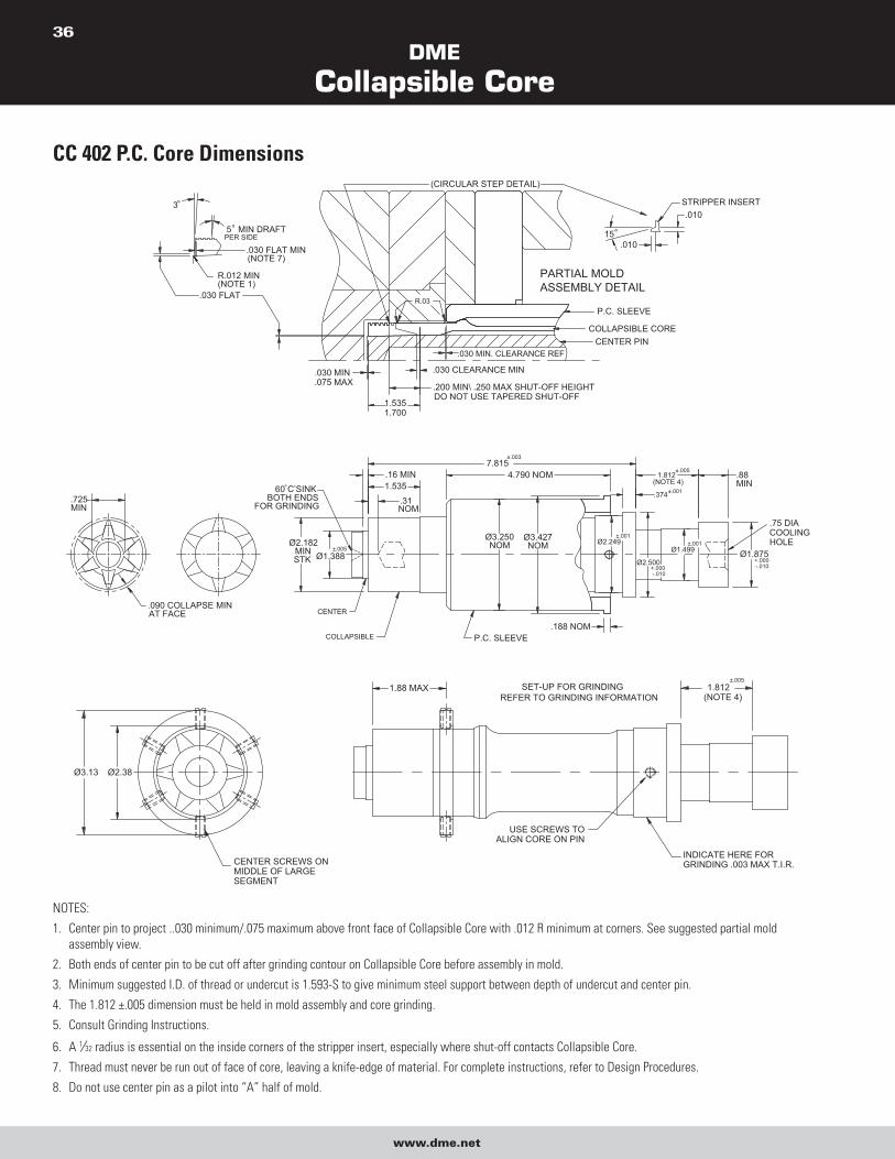
DME
Collapsible Core
www.dme.net
36
CC 402 P.C. Core Dimensions
CENTER PINCOLLAPSIBLE CORE
P.C. SLEEVE
60° C’SINKBOTH ENDS
FOR GRINDING.725MIN
.090 COLLAPSE MINAT FACE
R.012 MIN(NOTE 1)
.030 FLAT
.030 FLAT MIN(NOTE 7)
3°
5° MIN DRAFTPER SIDE
1.5351.700
.030 MIN
.075 MAX
1.812(NOTE 4)
.188 NOMP.C. SLEEVECOLLAPSIBLE
.200 MIN\ .250 MAX SHUT-OFF HEIGHTDO NOT USE TAPERED SHUT-OFF
Ø3.250NOM
7.8154.790 NOM
.31
.16 MIN1.535
Ø1.388
CENTER
NOM
Ø3.427NOM Ø2.249
Ø2.500
.374
PARTIAL MOLDASSEMBLY DETAIL
.88MIN
.75 DIA COOLINGHOLE
Ø1.499 Ø1.875
.010
15°
STRIPPER INSERT
.030 MIN. CLEARANCE REF
(CIRCULAR STEP DETAIL)
R.03
.010
Ø2.182MINSTK
±.005
-.010+.000
±.001
±.003
+.000-.010
±.001
±.001
±.005
.030 CLEARANCE MIN
CENTER SCREWS ONMIDDLE OF LARGESEGMENT
Ø3.13 Ø2.38
1.812(NOTE 4)
INDICATE HERE FORGRINDING .003 MAX T.I.R.
REFER TO GRINDING INFORMATION1.88 MAX
USE SCREWS TOALIGN CORE ON PIN
SET-UP FOR GRINDING±.005
NOTES:
1. Center pin to project ..030 minimum/.075 maximum above front face of Collapsible Core with .012 R minimum at corners. See suggested partial mold
assembly view.
2. Both ends of center pin to be cut off after grinding contour on Collapsible Core before assembly in mold.
3. Minimum suggested I.D. of thread or undercut is 1.593-S to give minimum steel support between depth of undercut and center pin.
4. The 1.812 ±.005 dimension must be held in mold assembly and core grinding.
5. Consult Grinding Instructions.
6. A 1⁄32 radius is essential on the inside corners of the stripper insert, especially where shut-off contacts Collapsible Core.
7. Thread must never be run out of face of core, leaving a knife-edge of material. For complete instructions, refer to Design Procedures.
8. Do not use center pin as a pilot into “A” half of mold.
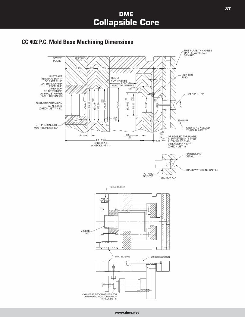
DME
Collapsible Core
www.dme.net
37
CC 402 P.C. Mold Base Machining Dimensions
STRIPPER INSERTMUST BE RETAINED
2.253
Ø2.
274
.740MIN.
.44
7.815
SHUT-OFF DIMENSIONAS NEEDED
(CHECK LIST 7 & 13)
SUBTRACTINTERNAL DEPTH
OF PART PLUSMATERIAL SHRINK
FROM THIS DIMENSION
TO DETERMINEACTUAL STRIPPERPLATE THICKNESS
PLATECAVITY
PLATESTRIPPER
PIN COOLINGDETAIL
BRASS WATERLINE BAFFLE“O” RINGGROOVE SECTION A-A
SUPPORTRING
THIS PLATE THICKNESSMAY BE VARIED ASDESIRED
SUPPORT RING, & RESTGRIND EJECTOR PLATE,
C'BORE AS NEEDEDTO HOLD 1.812
3/4 N.P.T. TAP
Ø1.
880
Ø2.
505
Ø2.
251
Ø3.
28
Ø3.
254
Ø3.
254
Ø3.
28
Ø3.
50
.375
.50
±.003
CORE O.A.L.(CHECK LIST 11)
+.001-.000
.207
±.00
7
+.00
3-.0
00
+.00
3-.0
00
-.002+.003
-.000
+.00
5
+.00
1-.0
00
1.187
-.000
+.00
5
±.001
DIMENSION 1.187BUTTONS TO THIS
(CHECK LIST 1) ±.001
.250 NOM
Ø1.
501
Ø1.
56
1.812±.005
+.00
1-.0
00
C-4.500
±.003
2.687
.875 1.375
±.005
EJECTOR STROKE.625
RELIEFFOR GREASE
.875 1.375
.187
1.000
±.005
A
(CHECK LIST 2)
GUIDED EJECTIONPARTING LINE
MOLDEDPART
CYLINDERS RECOMMENDED FORAUTOMATIC MOLD OPERATION
(CHECK LIST 5)

DME
Collapsible Core
www.dme.net
38
MOLD DESIGN CHECK LIST 1. Use guided ejector plates and a support ring around center pin. Ejector plate, support rings and rest buttons must be ground to 1.187 ±.001.
2. Use springs to assure first break at main parting line.
3. Return pins to end under stripper plate.
4. Ejector plate travel to specifications. Stamp dimension on edge of plate.
5. Secondary stripper plate actuation to begin only after full ejector plate travel. Stripper plate must return fully before ejector plate begins to
return (see Sequence Description).
6. Good venting is essential, preferable to outside of mold.
7. Clearance between core shut-off O.D. and stripper insert I.D. to be .0010/.0015 total. Measure core when installed in mold. No tapered
shut-off permitted. Avoid excessive shut-off length; .150/.250 is adequate.
8. Mounted core to be free to turn when in ejector plate assembly.
9. Center pin to be concentric with stripper bushing. Verify protrusion of pin through core and radius on tip of pin.
10. Positive collapse sleeve to travel freely through plates. Apply grease where indicated. Check for free movement when mold is at operating
temperature.
11. When face of Collapsible Core segments shut-off against cavity (some parts with through holes), all cores must be ground to the same
O.A.L. Normal tolerance of ±.003 is inadequate. Refer to Core Grinding Instructions. Clearance between end of core face and cavity to be
.0005 to .0010. Do not pre-load the core. Whenever the above condition exists, an early ejector plate return system must be used, or the
cores will be destroyed.
NOTE: This applies only when the core seals off against the cavity. When the pin is seating against the cavity exercise care to avoid
excessive pre-load of the pin. A .000 to .0015 interference is adequate.
12. Break all sharp corners.
13. The stripper shut-off diameter must be of the same diameter, or preferably, a large diameter than any other diameter on the core.
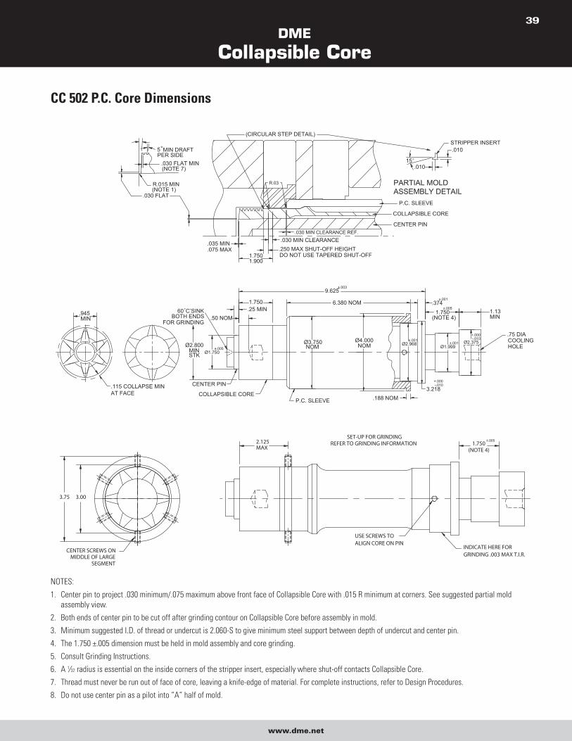
DME
Collapsible Core
www.dme.net
39
CC 502 P.C. Core Dimensions
CENTER PIN
COLLAPSIBLE CORE
P.C. SLEEVE
(CIRCULAR STEP DETAIL)
.030 MIN CLEARANCE.250 MAX SHUT-OFF HEIGHTDO NOT USE TAPERED SHUT-OFF
.030 MIN CLEARANCE REF.
P.C. SLEEVE
Ø3.750NOM
6.380 NOM
9.625
Ø1.750
.115 COLLAPSE MINAT FACE COLLAPSIBLE CORE
CENTER PIN
.945MIN .50 NOM
.25 MIN60° C’SINKBOTH ENDS
FOR GRINDING
1.750
.035 MIN
.075 MAX1.7501.900
Ø2.375Ø1.999Ø2.968
Ø4.000NOM
.188 NOM3.218
1.750(NOTE 4)
.374
.75 DIACOOLINGHOLE
1.13MIN
5° MIN DRAFTPER SIDE
.030 FLAT MIN(NOTE 7)
R.015 MIN(NOTE 1)
.030 FLAT
R.03
STRIPPER INSERT
15°
.010
.010
PARTIAL MOLDASSEMBLY DETAIL
Ø2.800MINSTK
±.005
-.010+.000
±.001
±.003
+.000-.010
±.001
±.005
±.001
3.75 3.00
±.005SET-UP FOR GRINDING
REFER TO GRINDING INFORMATION 1.750(NOTE 4)
USE SCREWS TOALIGN CORE ON PIN
2.125MAX
INDICATE HERE FORGRINDING .003 MAX T.I.R.
CENTER SCREWS ONMIDDLE OF LARGE
SEGMENT
NOTES:
1. Center pin to project .030 minimum/.075 maximum above front face of Collapsible Core with .015 R minimum at corners. See suggested partial mold
assembly view.
2. Both ends of center pin to be cut off after grinding contour on Collapsible Core before assembly in mold.
3. Minimum suggested I.D. of thread or undercut is 2.060-S to give minimum steel support between depth of undercut and center pin.
4. The 1.750 ±.005 dimension must be held in mold assembly and core grinding.
5. Consult Grinding Instructions.
6. A 1⁄32 radius is essential on the inside corners of the stripper insert, especially where shut-off contacts Collapsible Core.
7. Thread must never be run out of face of core, leaving a knife-edge of material. For complete instructions, refer to Design Procedures.
8. Do not use center pin as a pilot into “A” half of mold.
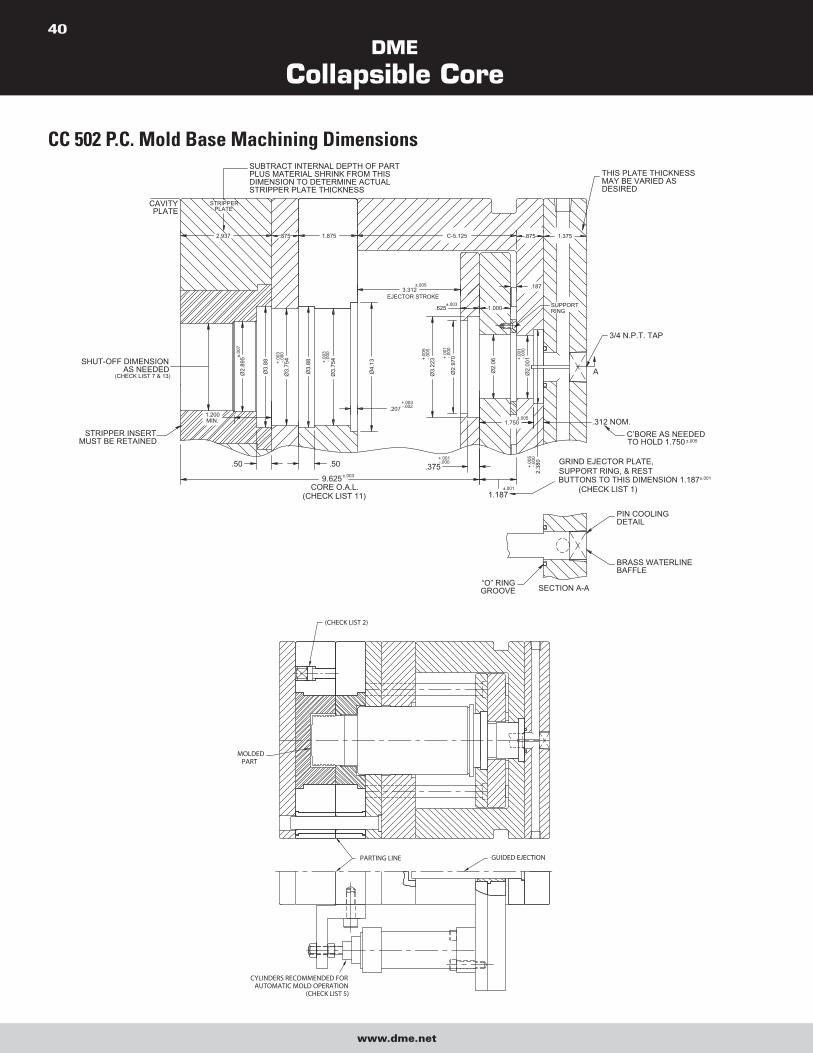
DME
Collapsible Core
www.dme.net
40
CC 502 P.C. Mold Base Machining DimensionsSUBTRACT INTERNAL DEPTH OF PARTPLUS MATERIAL SHRINK FROM THIS DIMENSION TO DETERMINE ACTUAL STRIPPER PLATE THICKNESS
Ø3.
223
3.312
Ø2.
970
±.003
C-5.125
.3759.625
Ø3.
754
Ø3.
88
Ø2.
895
Ø3.
754
Ø3.
88
Ø4.
13
1.200MIN.
STRIPPER INSERTMUST BE RETAINED
±.003
.207
CORE O.A.L.(CHECK LIST 11)
.50.50+.001-.000
+.003-.002
STRIPPER
2.937
SHUT-OFF DIMENSIONAS NEEDED
(CHECK LIST 7 & 13)
PLATECAVITY
PLATE
±.00
7
-.000
+.00
3
-.000
+.00
3
+.00
5-.0
00
-.000
+.00
1
EJECTOR STROKE
.625
±.005
1.875.875
1.750
2.38
0
Ø2.
001
Ø2.
06
C’BORE AS NEEDEDTO HOLD 1.750
SECTION A-A“O” RINGGROOVE
BRASS WATERLINEBAFFLE
PIN COOLINGDETAIL
.312 NOM.
1.187±.001
-.000
+.00
5
±.005
±.001
GRIND EJECTOR PLATE,SUPPORT RING, & REST BUTTONS TO THIS DIMENSION 1.187 (CHECK LIST 1)
±.005
SUPPORTRING
-.000
+.00
1
1.000
.187
3/4 N.P.T. TAP
1.375.875
THIS PLATE THICKNESSMAY BE VARIED ASDESIRED
A
GUIDED EJECTIONPARTING LINE
MOLDEDPART
(CHECK LIST 2)
CYLINDERS RECOMMENDED FORAUTOMATIC MOLD OPERATION
(CHECK LIST 5)

DME
Collapsible Core
www.dme.net
41
MOLD DESIGN CHECK LIST 1. Use guided ejector plates and a support ring around center pin. Ejector plate, support rings and rest buttons must be ground to 1.187 ±.001.
2. Use springs to assure first break at main parting line.
3. Return pins to end under stripper plate.
4. Ejector plate travel to specifications. Stamp dimension on edge of plate.
5. Secondary stripper plate actuation to begin only after full ejector plate travel. Stripper plate must return fully before ejector plate begins to
return (see Sequence Description).
6. Good venting is essential, preferable to outside of mold.
7. Clearance between core shut-off O.D. and stripper insert I.D. to be .0010/.0015 total. Measure core when installed in mold. No tapered
shut-off permitted. Avoid excessive shut-off length; .150/.250 is adequate.
8. Mounted core to be free to turn when in ejector plate assembly.
9. Center pin to be concentric with stripper bushing. Verify protrusion of pin through core and radius on tip of pin.
10. Positive collapse sleeve to travel freely through plates. Apply grease where indicated. Check for free movement when mold is at operating
temperature.
11. When face of Collapsible Core segments shut-off against cavity (some parts with through holes), all cores must be ground to the same
O.A.L. Normal tolerance of ±.003 is inadequate. Refer to Core Grinding Instructions. Clearance between end of core face and cavity to be
.0005 to .0010. Do not pre-load the core. Whenever the above condition exists, an early ejector plate return system must be used, or the
cores will be destroyed.
NOTE: This applies only when the core seals off against the cavity. When the pin is seating against the cavity exercise care to avoid
excessive pre-load of the pin. A .000 to .0015 interference is adequate.
12. Break all sharp corners.
13. The stripper shut-off diameter must be of the same diameter, or preferably, a large diameter than any other diameter on the core.
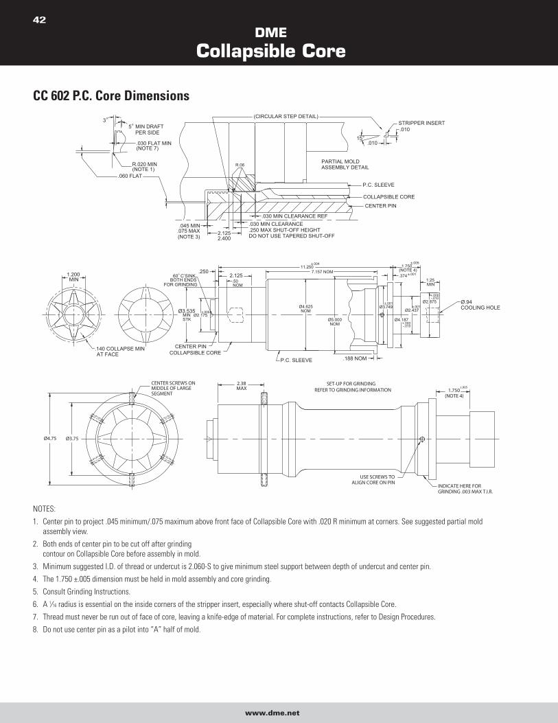
DME
Collapsible Core
www.dme.net
42
CC 602 P.C. Core Dimensions
2.125
11.250
Ø3.535MINSTK
Ø2.175
.140 COLLAPSE MINAT FACE COLLAPSIBLE CORE
CENTER PIN
1.200MIN
.25060° C’SINK
BOTH ENDSFOR GRINDING
.50NOM
1.25 MIN
Ø2.875
Ø2.437
Ø4.187
Ø3.749
Ø5.000NOM
Ø4.625NOM
P.C. SLEEVE .188 NOM
7.157 NOM1.750
.374(NOTE 4)
Ø.94COOLING HOLE
±.005
±.004
-.010+.000
±.001±.001
±.001
±.005
-.010+.000
R.06
(CIRCULAR STEP DETAIL)
.250 MAX SHUT-OFF HEIGHTDO NOT USE TAPERED SHUT-OFF2.125
2.400
.045 MIN.075 MAX(NOTE 3)
5° MIN DRAFTPER SIDE
R.020 MIN(NOTE 1)
.030 FLAT MIN(NOTE 7)
.060 FLAT
P.C. SLEEVE
COLLAPSIBLE CORE
CENTER PIN
PARTIAL MOLDASSEMBLY DETAIL
.030 MIN CLEARANCE REF
STRIPPER INSERT
.01015°
.010
.030 MIN CLEARANCE
3°
±.005CENTER SCREWS ONMIDDLE OF LARGESEGMENT
Ø4.75 Ø3.75
2.38MAX
USE SCREWS TOALIGN CORE ON PIN
INDICATE HERE FORGRINDING .003 MAX T.I.R.
SET-UP FOR GRINDINGREFER TO GRINDING INFORMATION 1.750
(NOTE 4)
NOTES:
1. Center pin to project .045 minimum/.075 maximum above front face of Collapsible Core with .020 R minimum at corners. See suggested partial mold
assembly view.
2. Both ends of center pin to be cut off after grinding
contour on Collapsible Core before assembly in mold.
3. Minimum suggested I.D. of thread or undercut is 2.060-S to give minimum steel support between depth of undercut and center pin.
4. The 1.750 ±.005 dimension must be held in mold assembly and core grinding.
5. Consult Grinding Instructions.
6. A 1⁄16 radius is essential on the inside corners of the stripper insert, especially where shut-off contacts Collapsible Core.
7. Thread must never be run out of face of core, leaving a knife-edge of material. For complete instructions, refer to Design Procedures.
8. Do not use center pin as a pilot into “A” half of mold.
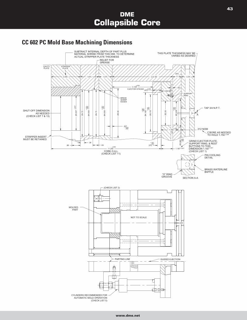
DME
Collapsible Core
www.dme.net
43
CC 602 PC Mold Base Machining Dimensions
.187
C-6.187
1.000
1.750
“O” RINGGROOVE
3.000
SHUT-OFF DIMENSIONAS NEEDED
(CHECK LIST 7 & 13)
11.250
STRIPPER INSERTMUST BE RETAINED
CAVITYPLATE
Ø4.
192
Ø3.
751
Ø4.
630
Ø4.
75
Ø5.
06
Ø2.
50
Ø3.
557
Ø4.
75
Ø4.
630
.207
CORE O.A.L.(CHECK LIST 11)
.38.88 .63
±.004
+.003-.002
.375-.000+.001
1.375
BREAKSHARPEDGES
RELIEF FORGREASE
±.00
7
-.000
+.00
3
-.000
+.00
3
SUBTRACT INTERNAL DEPTH OF PART PLUS MATERIAL SHRINK FROM THIS DIM. TO DETERMINEACTUAL STRIPPER PLATE THICKNESS
1.875
STRIPPERPLATE
±.005
EJECTOR STROKE4.125
+.00
1
+.00
5-.0
00 -.000
.875±.003
Ø2.
880
Ø2.
439
±.005
PIN COOLINGDETAIL
BRASS WATERLINEBAFFLE
SECTION A-A
BUTTONS TO THISDIMENSION 1.187
.312 NOM
SUPPORT RING, & RESTGRIND EJECTOR PLATE,
1.187 ±.001
+.00
5-.0
00
(CHECK LIST 1)
±.005
±.001
C’BORE AS NEEDEDTO HOLD 1.750
TAP 3/4 N.P.T.
+.00
1-.0
00
SUPPORTRING
THIS PLATE THICKNESS MAY BE VARIED AS DESIRED
1.375
.875
A
NOT TO SCALE
MOLDEDPART
PARTING LINE GUIDED EJECTION
(CHECK LIST 2)
CYLINDERS RECOMMENDED FORAUTOMATIC MOLD OPERATION
(CHECK LIST 5)

DME
Collapsible Core
www.dme.net
44
MOLD DESIGN CHECK LIST 1. Use guided ejector plates and a support ring around center pin. Ejector plate, support rings and rest buttons must be ground to 1.187 ±.001.
2. Use springs to assure first break at main parting line.
3. Return pins to end under stripper plate.
4. Ejector plate travel to specifications. Stamp dimension on edge of plate.
5. Secondary stripper plate actuation to begin only after full ejector plate travel. Stripper plate must return fully before ejector plate begins to
return (see Sequence Description).
6. Good venting is essential, preferable to outside of mold.
7. Clearance between core shut-off O.D. and stripper insert I.D. to be .0013/.0018 total. Measure core when installed in mold. No tapered
shut-off permitted. Avoid excessive shut-off length; .250 maximum is adequate.
8. Mounted core to be free to turn when in ejector plate assembly.
9. Center pin to be concentric with stripper bushing. Verify protrusion of pin through core and radius on tip of pin.
10. Positive collapse sleeve to travel freely through plates. Apply grease where indicated. Check for free movement when mold is at operating
temperature.
11. When face of Collapsible Core segments shut-off against cavity (some parts with through holes), all cores must be ground to the same
O.A.L. Normal tolerance of ±.003 is inadequate. Refer to Core Grinding Instructions. Clearance between end of core face and cavity to be
.0005 to .0010. Do not pre-load the core. Whenever the above condition exists, an early ejector plate return system must be used, or the
cores will be destroyed.
NOTE: This applies only when the core seals off against the cavity. When the pin is seating against the cavity exercise care to avoid
excessive pre-load of the pin. A .000 to .0015 interference is adequate.
12. Break all sharp corners.
13. The stripper shut-off diameter must be of the same diameter, or preferably, a large diameter than any other diameter on the core.
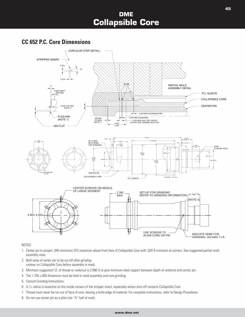
DME
Collapsible Core
www.dme.net
45
CC 652 P.C. Core Dimensions
11.250±.004
2.400
0.500NOM
7.157 NOM0.375
CENTER PIN
COLLAPSIBLE CORE
Ø2.450 ±.005Ø3.800
MINSTK
P.C. SLEEVE
Ø5.265NOM
Ø4.900NOM
0.188 NOM
1.250MIN
60° C'SINKBOTH ENDSFOR GRINDING
Ø4.024 ±.001
Ø4.450 +.000-.010
Ø2.712 ±.001
Ø3.150+.000-.010
1.750±.005
(NOTE 4)
0.374 ±.001
Ø.937COOLING HOLE
0.150 COLLAPSE MINAT FACE
1.520MIN
15°
0.010
0.010
STRIPPER INSERT
(CIRCULAR STEP DETAIL)
5°MIN DRAFTPER SIDE
3°
R.020 MIN(NOTE 1)
.060 FLAT
0.030 FLAT MIN(NOTE 7)
.045 MIN.075 MAX(NOTE 1)
R.06
0.030 MIN CLEARANCE REF
2.2502.400
0.250 MAX SHUT OFF HEIGHTDO NOT USE TAPERED SHUT OFF
0.030 MIN CLEARANCE
PARTIAL MOLDASSEMBLY DETAIL
P.C. SLEEVE
COLLAPSIBLE CORE
CENTER PIN
USE SCREWS TO ALIGN CORE ON PIN INDICATE HERE FOR
GRINDING .003 MAX T.I.R.
1.750±.005
(NOTE 4)
SET-UP FOR GRINDINGREFER TO GRINDING INFORMATION
2.380MAX
4.0004.800
CENTER SCREWS ON MIDDLE OF LARGE SEGMENT
NOTES:
1. Center pin to project .045 minimum/.075 maximum above front face of Collapsible Core with .020 R minimum at corners. See suggested partial mold
assembly view.
2. Both ends of center pin to be cut off after grinding
contour on Collapsible Core before assembly in mold.
3. Minimum suggested I.D. of thread or undercut is 2.890-S to give minimum steel support between depth of undercut and center pin.
4. The 1.750 ±.005 dimension must be held in mold assembly and core grinding.
5. Consult Grinding Instructions.
6. A 1⁄16 radius is essential on the inside corners of the stripper insert, especially where shut-off contacts Collapsible Core.
7. Thread must never be run out of face of core, leaving a knife-edge of material. For complete instructions, refer to Design Procedures.
8. Do not use center pin as a pilot into “A” half of mold.
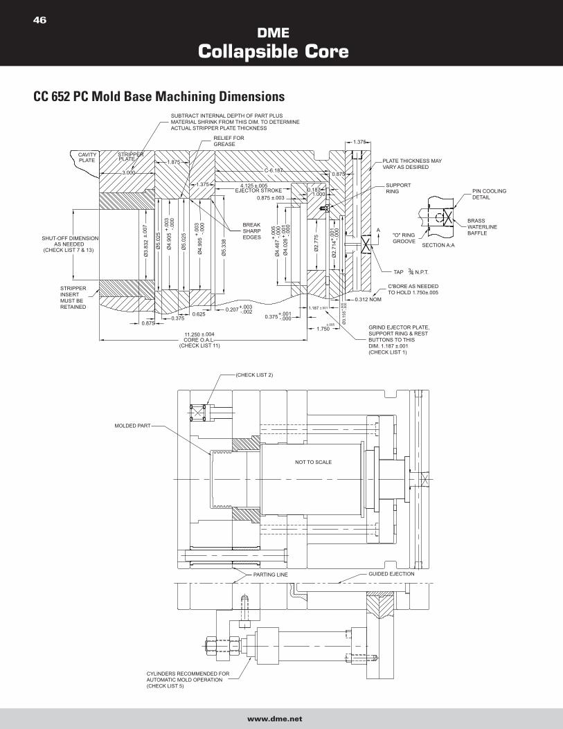
DME
Collapsible Core
www.dme.net
46
CC 652 PC Mold Base Machining Dimensions
PLATECAVITY STRIPPER
PLATE
SHUT-OFF DIMENSIONAS NEEDED
(CHECK LIST 7 & 13)
Ø3.
832
±.00
7
Ø5.
025
Ø4.
905
+.00
3-.0
00
Ø5.
025
Ø4.
905
+.00
3-.0
00
Ø5.
338
4.125 ±.005EJECTOR STROKE
0.875 ±.003
PLATE THICKNESS MAY VARY AS DESIRED
SUBTRACT INTERNAL DEPTH OF PART PLUSMATERIAL SHRINK FROM THIS DIM. TO DETERMINEACTUAL STRIPPER PLATE THICKNESS
3.000
RELIEF FORGREASE
1.875
1.375
0.8750.375
0.6250.207+.003
-.002
Ø4.
026
+.00
1-.0
00
Ø4.
467+.
005
-.000
Ø2.
775
Ø2.
714+
.001
-.000
Ø3.
155+.
005
-.000
11.250 ±.004CORE O.A.L.
(CHECK LIST 11)
0.1871.000
SUPPORT RING
A
TAP 34 N.P.T.
STRIPPER INSERT MUST BE RETAINED
1.750±.005
1.187 ±.001
0.375+.001-.000
GRIND EJECTOR PLATE,SUPPORT RING & RESTBUTTONS TO THISDIM. 1.187 ±.001(CHECK LIST 1)
C-6.1870.875
1.375
SECTION A:A
"O" RINGGROOVE
BRASS WATERLINEBAFFLE
PIN COOLING DETAIL
0.312 NOM
C'BORE AS NEEDEDTO HOLD 1.750±.005
BREAK SHARP EDGES
NOT TO SCALE
MOLDED PART
(CHECK LIST 2)
PARTING LINE GUIDED EJECTION
CYLINDERS RECOMMENDED FORAUTOMATIC MOLD OPERATION(CHECK LIST 5)
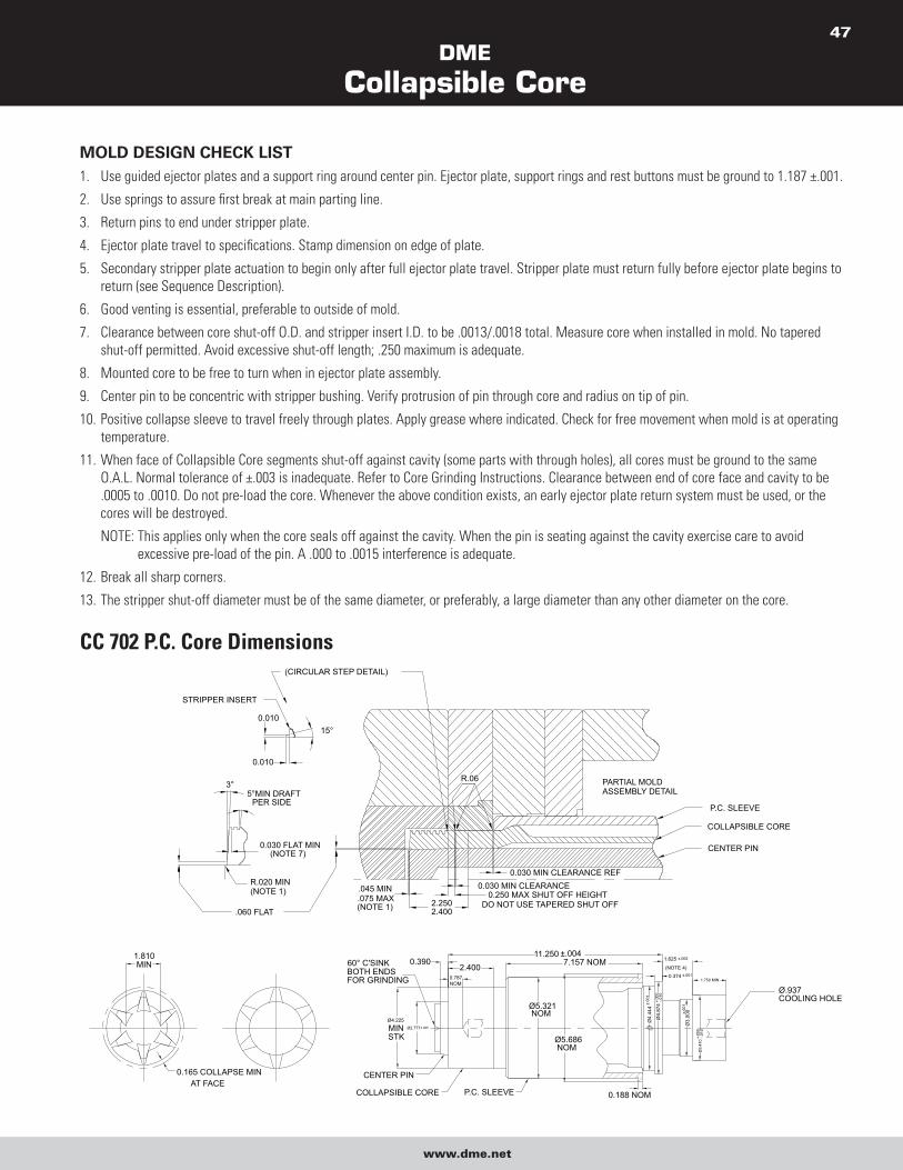
DME
Collapsible Core
www.dme.net
47
MOLD DESIGN CHECK LIST 1. Use guided ejector plates and a support ring around center pin. Ejector plate, support rings and rest buttons must be ground to 1.187 ±.001.
2. Use springs to assure first break at main parting line.
3. Return pins to end under stripper plate.
4. Ejector plate travel to specifications. Stamp dimension on edge of plate.
5. Secondary stripper plate actuation to begin only after full ejector plate travel. Stripper plate must return fully before ejector plate begins to
return (see Sequence Description).
6. Good venting is essential, preferable to outside of mold.
7. Clearance between core shut-off O.D. and stripper insert I.D. to be .0013/.0018 total. Measure core when installed in mold. No tapered
shut-off permitted. Avoid excessive shut-off length; .250 maximum is adequate.
8. Mounted core to be free to turn when in ejector plate assembly.
9. Center pin to be concentric with stripper bushing. Verify protrusion of pin through core and radius on tip of pin.
10. Positive collapse sleeve to travel freely through plates. Apply grease where indicated. Check for free movement when mold is at operating
temperature.
11. When face of Collapsible Core segments shut-off against cavity (some parts with through holes), all cores must be ground to the same
O.A.L. Normal tolerance of ±.003 is inadequate. Refer to Core Grinding Instructions. Clearance between end of core face and cavity to be
.0005 to .0010. Do not pre-load the core. Whenever the above condition exists, an early ejector plate return system must be used, or the
cores will be destroyed.
NOTE: This applies only when the core seals off against the cavity. When the pin is seating against the cavity exercise care to avoid
excessive pre-load of the pin. A .000 to .0015 interference is adequate.
12. Break all sharp corners.
13. The stripper shut-off diameter must be of the same diameter, or preferably, a large diameter than any other diameter on the core.
CC 702 P.C. Core Dimensions
CENTER PIN
COLLAPSIBLE CORE
P.C. SLEEVE
PARTIAL MOLDASSEMBLY DETAIL
0.030 MIN CLEARANCE0.250 MAX SHUT OFF HEIGHT
DO NOT USE TAPERED SHUT OFF2.2502.400
0.030 MIN CLEARANCE REF
R.06
.045 MIN.075 MAX(NOTE 1)
0.030 FLAT MIN(NOTE 7)
.060 FLAT
R.020 MIN(NOTE 1)
3°5°MIN DRAFT
PER SIDE
(CIRCULAR STEP DETAIL)
STRIPPER INSERT
0.010
0.01015°
Ø5.321NOM
Ø5.686NOM
Ø4.225
MINSTK
Ø2.777±.005
P.C. SLEEVECOLLAPSIBLE CORE
CENTER PIN
60° C'SINKBOTH ENDSFOR GRINDING
Ø.937COOLING HOLE
11.250 ±.0047.157 NOM2.400
0.787NOM
0.390
0.188 NOM
Ø4.
444
±.00
1
Ø4.
874
-.010
Ø3.
000±.00
1
Ø3.
410
-.010
+.00
0
1.750 MIN
1.625 ±.005
(NOTE 4)0.374 ±.001
0.165 COLLAPSE MINAT FACE
1.810MIN
+.00
0
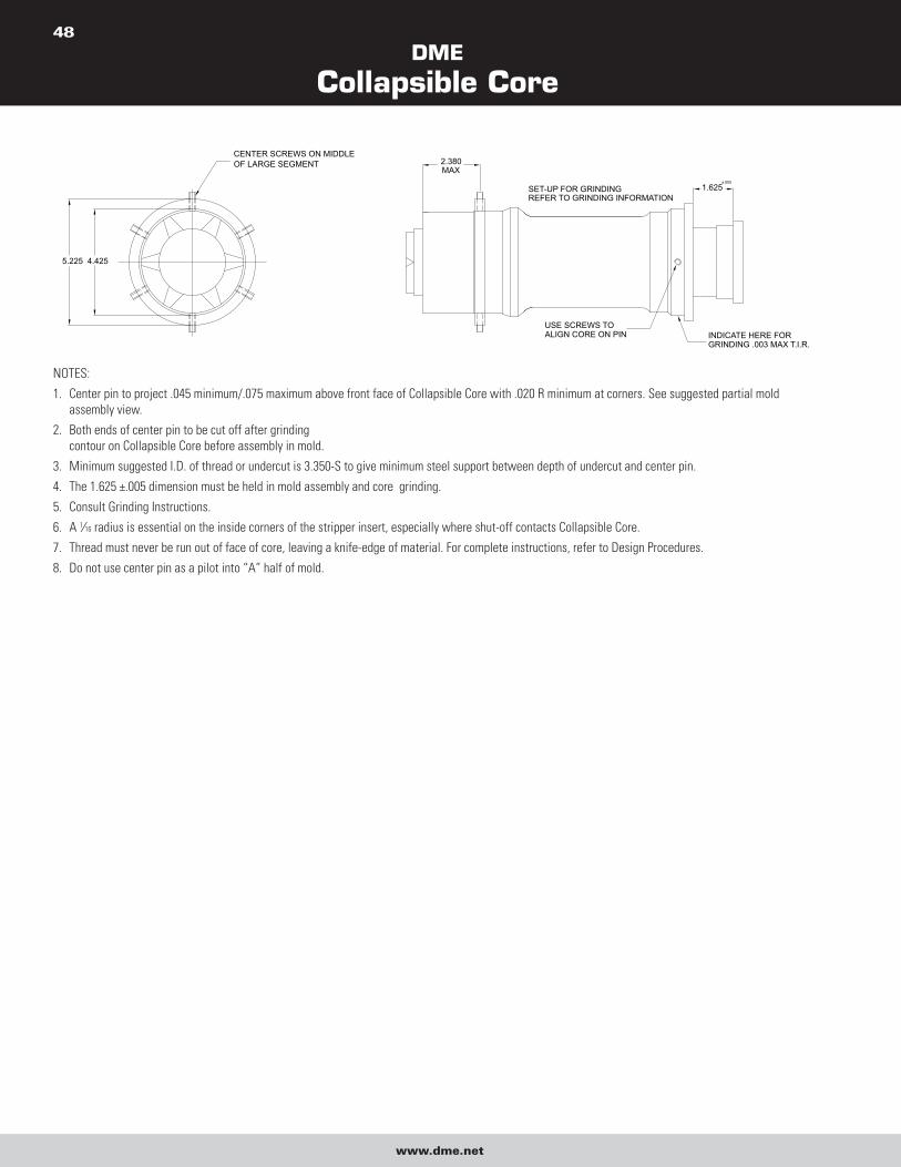
DME
Collapsible Core
www.dme.net
48
1.625±.005
INDICATE HERE FOR GRINDING .003 MAX T.I.R.
USE SCREWS TO ALIGN CORE ON PIN
SET-UP FOR GRINDINGREFER TO GRINDING INFORMATION
CENTER SCREWS ON MIDDLE OF LARGE SEGMENT 2.380
MAX
4.4255.225
NOTES:
1. Center pin to project .045 minimum/.075 maximum above front face of Collapsible Core with .020 R minimum at corners. See suggested partial mold
assembly view.
2. Both ends of center pin to be cut off after grinding
contour on Collapsible Core before assembly in mold.
3. Minimum suggested I.D. of thread or undercut is 3.350-S to give minimum steel support between depth of undercut and center pin.
4. The 1.625 ±.005 dimension must be held in mold assembly and core grinding.
5. Consult Grinding Instructions.
6. A 1⁄16 radius is essential on the inside corners of the stripper insert, especially where shut-off contacts Collapsible Core.
7. Thread must never be run out of face of core, leaving a knife-edge of material. For complete instructions, refer to Design Procedures.
8. Do not use center pin as a pilot into “A” half of mold.
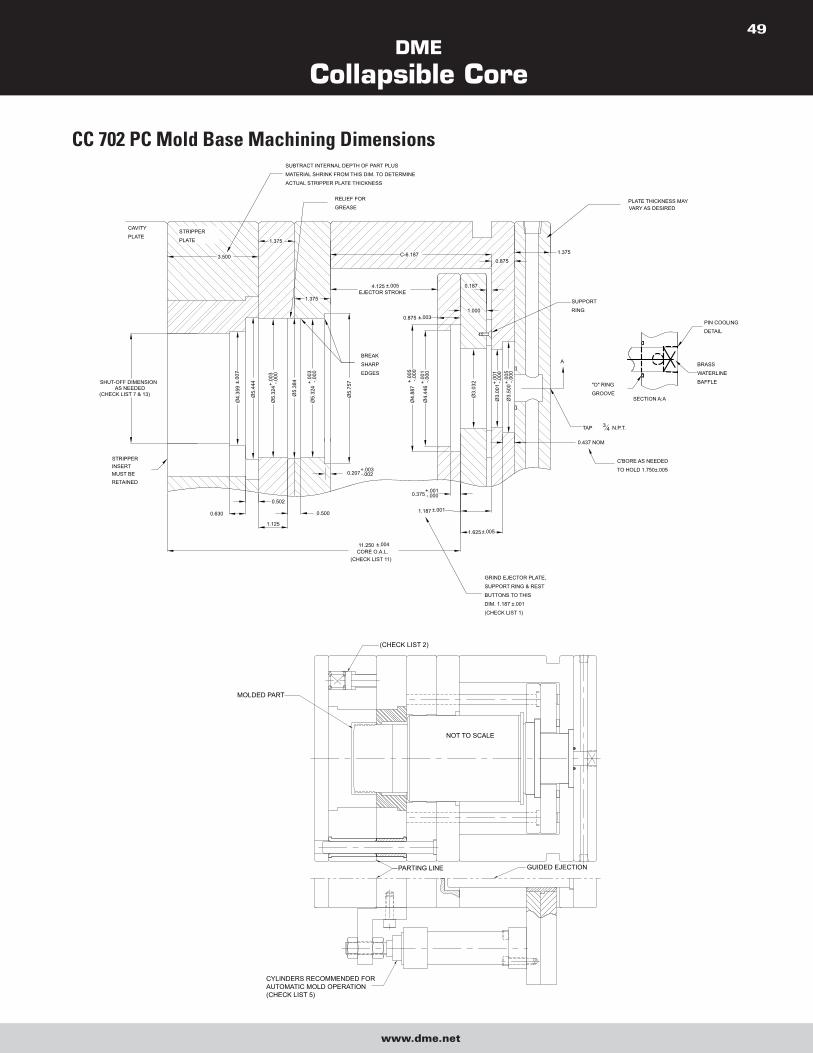
DME
Collapsible Core
www.dme.net
49
CC 702 PC Mold Base Machining Dimensions
SHUT-OFF DIMENSIONAS NEEDED
(CHECK LIST 7 & 13)
STRIPPER INSERT MUST BE RETAINED
GRIND EJECTOR PLATE,
SUPPORT RING & REST
BUTTONS TO THIS
DIM. 1.187 ±.001
(CHECK LIST 1)
C'BORE AS NEEDED
TO HOLD 1.750±.005
SUPPORT
RING
PLATE THICKNESS MAY VARY AS DESIRED
RELIEF FOR
GREASE
SUBTRACT INTERNAL DEPTH OF PART PLUS
MATERIAL SHRINK FROM THIS DIM. TO DETERMINE
ACTUAL STRIPPER PLATE THICKNESS
STRIPPER
PLATE
BREAK
SHARP
EDGES
11.250 ±.004CORE O.A.L.
(CHECK LIST 11)
3.500
CAVITY
PLATE1.375
1.375
C-6.187
4.125 ±.005EJECTOR STROKE
0.875
1.0000.875 ±.003
Ø4.
359
±.00
7
Ø5.
444
Ø5.
324+.
003
-.000
Ø5.
384
Ø5.
324
+.00
3-.0
00
Ø5.
757
0.630
1.125
0.502
0.500
0.207+.003-.002
1.625±.005
1.187 ±.001
0.375+.001-.000
Ø4.
446
+.00
1-.0
00
Ø4.
887
+.00
5-.0
00
0.187
0.437 NOM
PIN COOLING
DETAIL
BRASS
WATERLINE
BAFFLE"O" RING
GROOVESECTION A:A
1.375
Ø3.
032
Ø3.
001+.
001
-.000
Ø3.
500+.
005
-.000
A
TAP 34 N.P.T.
CYLINDERS RECOMMENDED FORAUTOMATIC MOLD OPERATION(CHECK LIST 5)
GUIDED EJECTIONPARTING LINE
(CHECK LIST 2)
MOLDED PART
NOT TO SCALE
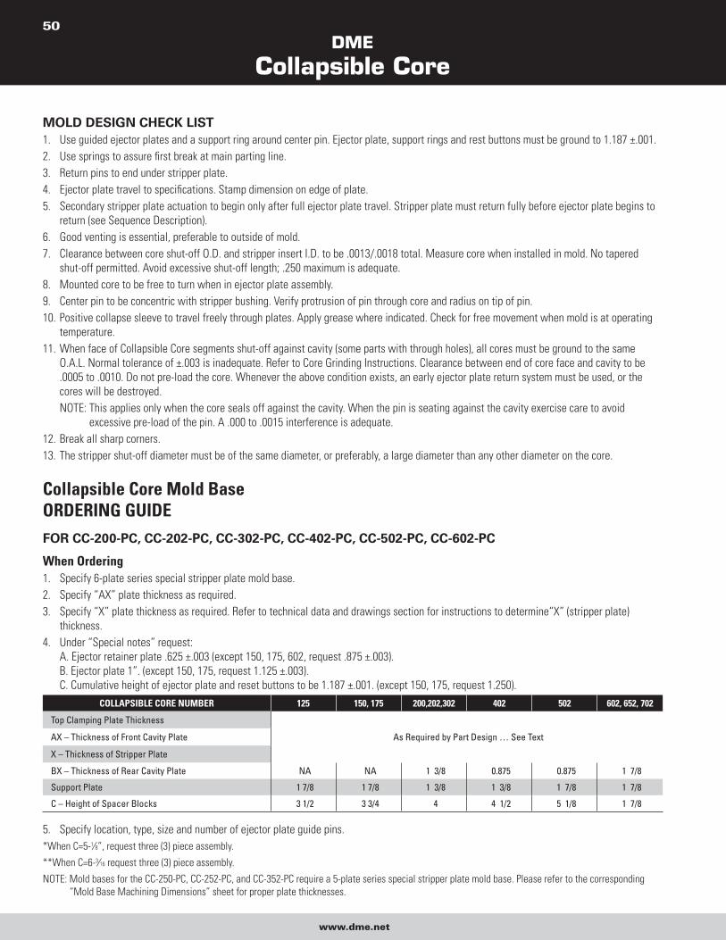
DME
Collapsible Core
www.dme.net
50
MOLD DESIGN CHECK LIST 1. Use guided ejector plates and a support ring around center pin. Ejector plate, support rings and rest buttons must be ground to 1.187 ±.001.
2. Use springs to assure first break at main parting line.
3. Return pins to end under stripper plate.
4. Ejector plate travel to specifications. Stamp dimension on edge of plate.
5. Secondary stripper plate actuation to begin only after full ejector plate travel. Stripper plate must return fully before ejector plate begins to
return (see Sequence Description).
6. Good venting is essential, preferable to outside of mold.
7. Clearance between core shut-off O.D. and stripper insert I.D. to be .0013/.0018 total. Measure core when installed in mold. No tapered
shut-off permitted. Avoid excessive shut-off length; .250 maximum is adequate.
8. Mounted core to be free to turn when in ejector plate assembly.
9. Center pin to be concentric with stripper bushing. Verify protrusion of pin through core and radius on tip of pin.
10. Positive collapse sleeve to travel freely through plates. Apply grease where indicated. Check for free movement when mold is at operating
temperature.
11. When face of Collapsible Core segments shut-off against cavity (some parts with through holes), all cores must be ground to the same
O.A.L. Normal tolerance of ±.003 is inadequate. Refer to Core Grinding Instructions. Clearance between end of core face and cavity to be
.0005 to .0010. Do not pre-load the core. Whenever the above condition exists, an early ejector plate return system must be used, or the
cores will be destroyed.
NOTE: This applies only when the core seals off against the cavity. When the pin is seating against the cavity exercise care to avoid
excessive pre-load of the pin. A .000 to .0015 interference is adequate.
12. Break all sharp corners.
13. The stripper shut-off diameter must be of the same diameter, or preferably, a large diameter than any other diameter on the core.
Collapsible Core Mold BaseORDERING GUIDEFOR CC-200-PC, CC-202-PC, CC-302-PC, CC-402-PC, CC-502-PC, CC-602-PC
When Ordering1. Specify 6-plate series special stripper plate mold base.
2. Specify “AX” plate thickness as required.
3. Specify “X” plate thickness as required. Refer to technical data and drawings section for instructions to determine“X” (stripper plate)
thickness.
4. Under “Special notes” request:
A. Ejector retainer plate .625 ±.003 (except 150, 175, 602, request .875 ±.003).
B. Ejector plate 1”. (except 150, 175, request 1.125 ±.003).
C. Cumulative height of ejector plate and reset buttons to be 1.187 ±.001. (except 150, 175, request 1.250).
COLLAPSIBLE CORE NUMBER 125 150, 175 200,202,302 402 502 602, 652, 702
Top Clamping Plate Thickness
As Required by Part Design … See TextAX – Thickness of Front Cavity Plate
X – Thickness of Stripper Plate
BX – Thickness of Rear Cavity Plate NA NA 1 3/8 0.875 0.875 1 7/8
Support Plate 1 7/8 1 7/8 1 3/8 1 3/8 1 7/8 1 7/8
C – Height of Spacer Blocks 3 1/2 3 3/4 4 4 1/2 5 1/8 1 7/8
5. Specify location, type, size and number of ejector plate guide pins.
*When C=5-1⁄8”, request three (3) piece assembly.
**When C=6-3⁄16 request three (3) piece assembly.
NOTE: Mold bases for the CC-250-PC, CC-252-PC, and CC-352-PC require a 5-plate series special stripper plate mold base. Please refer to the corresponding
“Mold Base Machining Dimensions” sheet for proper plate thicknesses.
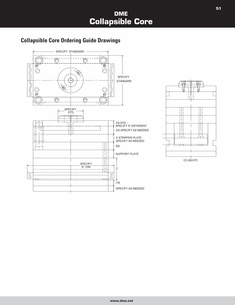
DME
Collapsible Core
www.dme.net
51
Collapsible Core Ordering Guide Drawings
SPECIFY“E” DIM
SPECIFY STANDARD
7/8 STD. -SPECIFY IF DIFFERENT
CC-602-PC
SPECIFY AS NEEDED
7/8
SUPPORT PLATE
X STRIPPER PLATESPECIFY AS NEEDED
BX
AX SPECIFY AS NEEDED
SPECIFYSTANDARD
SPECIFY STD.
C
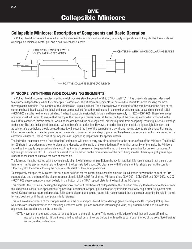
DME
Collapsible Minicore
www.dme.net
52
Collapsible Minicore: Description of Components and Basic OperationThe Collapsible Minicore is a three-unit assembly designed for simplicity of installation, reliability in operation and long life.The three units are
a Collapsible Minicore, center pin, and a positive collapse sleeve.
POSITIVE COLLAPSE SLEEVE (PC SLEEVE)
CENTER PIN WITH (3) NON-COLLAPSING BLADESCOLLAPSIBLE MINICORE WITH(3) COLLAPSING SEGMENTS
MINICORE (WITH THREE WIDE COLLAPSING SEGMENTS)The Collapsible Minicore is manufactured from AISI type A-2 steel hardened to 51 to 57 Rockwell “C”. It has three wide segments designed
to collapse independently when the center pin is withdrawn. The fit between segments is controlled to permit flash-free molding for most
thermoplastic materials. The location of the Minicore on its pin is critical. The distance between the back of the core head and the front of the
center pin head (head space) is critical and must be maintained for both grinding and in the mold. A grinding head space dimension of 1.562
+.005/.-000 must be held for core grinding. The head space dimension held in the mold base assembly is 1.562 +.000/-.005. These tolerances
are intentionally different to ensure that the top of the center pin blades never fall below the top of the core segments when installed in the
mold. If this occurred, plastic material would be molded behind the core segments, preventing them from collapsing, resulting in serious damage
to the core. The unit is designed to operate without benefit of lubrication. However, if lubrication is permissible, a lightweight lubricant such
as polytetrafluoroethylene should be used since it will extend the life of the components as with any moving steel to steel contact. Plating the
Minicore segments or its center pin is not recommended. However, certain alloying processes have been successfully used for wear reduction or
corrosion resistance. Please consult our Applications Engineering Department for specific details.
The individual segments have a “self-cleaning” action and will tend to carry any dirt or deposits to the outer surface of the Minicore. The first 50
to 100 shots in operation may show foreign matter deposits on the inside of the molded part. Prior to final assembly of the mold, the Minicore
should be thoroughly degreased and cleaned. A light wipe of grease can be given to the top of the center pin radius for break-in purposes. A
lightweight lubrication of P.T.F.E. should be used if possible, based on the requirements of the parts being molded. A heavyweight grease type
lubrication must not be used on the core or center pin.
The Minicore must be located with a key to closely align it with the center pin. Before the key is installed, it is recommended that the core be
free to turn in the ejector retainer plate. Even with the key installed, about .005 clearance with the alignment flat should permit the core to
“float” slightly, therefore allowing the core to locate itself on the center pin blades.
To completely collapse the Minicore, the core must be lifted off the center pin a specified amount. This distance between the back of the “BX”
support plate and the front of the ejector retainer plate is 1.688 ±.005 for all three Minicore sizes: CCM-0001, CCM-0002 and CCM-0003. A .207
+.003/-.002 deep counterbore must be held in the bottom of the “BX” support plate for the head of the PC sleeve.
This actuates the PC sleeve, causing the segments to collapse if they have not collapsed from their built-in memory. If necessary to deviate from
this dimension, consult our Applications Engineering Department. Stripper plate actuation by cylinders must only begin after full ejector plate
travel. Cylinders must return stripper plate fully before ejector plate begins return. It is recommended that the ejector assembly be held in its full
forward position until the stripper plate is fully returned.
This will avoid interference of the stripper insert with the core and possible Minicore damage (see Core Sequence Description). Collapsible
Minicores are individually fitted to a matching numbered center pin and cannot be interchanged. Also, only assemble core and pin with the
alignment flats parallel and on the same side.
NOTE: Never permit a ground thread to run out through the top of the core. This leaves a knife edge of steel that will break off in time.
Instruct the grinder to lift the thread grinding wheel out of the core before the thread breaks through the top of the core. See drawing
in core grinding instructions.
DME
Collapsible Minicore
www.dme.net
53
CENTER PIN (WITH THREE NON-COLLAPSING NARROW BLADES)The center pin serves to expand the segments of the Minicore to their molding position and holds them at this diameter. Blades at the molding
end of the center pin fit closely between the collapsing segments of the Minicore. When the core is lifted off the center pin blades, room is
provided for the Minicore segments to collapse. A hole is provided in the center pin for cooling. The center pin is manufactured of a high alloy
type D-6 tool steel hardened to 60 to 65 Rockwell “C”, except for the head area, which is a soft stainless steel, and is brazed to the center pin
shaft. Refer to the pin grinding instructions for machining directions. In use, the pin must incorporate two design features. The pin must protrude
beyond the top of the Minicore segments by certain amounts; refer to Dimension F in the Table of Dimensions. A radius must be applied to the
.300, .420, or .560 diameters of the center pin above the top of the core. This protrusion must keep material from flowing behind the segments
that would prevent their collapse. The sharp edge resulting from cutting the pin to length will gall and subsequently destroy the inside surfaces
The standard mold base machining dimensions provided in the Collapsible Minicore drawings assume a maximum pin protrusion of .031. When
greater protrusion is needed, a special center pin and certain dimensions in the mold base must be altered. Please consult with our Applications
Engineering Department. Center pins are fitted to a specific core and cannot be interchanged. Always assemble core and pin with alignment
flats parallel and on the same side. Always verify serial numbers and flat alignment of core and pin prior to assembly or grinding. Replacement
center pins to fit Collapsible Minicores are available on special order.
POSITIVE COLLAPSE SLEEVEThe positive collapse sleeve (PC sleeve) is designed to function when any of the Collapsible Minicore segments fail to collapse independently upon
withdrawal of the center pin. In normal operation, the PC sleeve is not functioning. It is essential to have such a unit for maximum safety and reliability
in automatic and semi-automatic operation. Under no circumstances should a mold be placed into operation without the use of the PC Sleeve.
The PC sleeve is uncomplicated in operation. An angular surface on the inside of the front edge of the PC sleeve will engage a matching angular
surface on the outside of the Collapsible Minicore when the un-collapsed Minicore is moved forward in the PC sleeve. This interference action
is achieved by restricting the travel of the PC sleeve to an amount less than the forward travel of the Collapsible Minicore.
It is essential that no variation be permitted from the dimension given between the rear of the back support and the front of the ejector retainer
plate. The .207 +.003/-.002 deep counterbore for the head of the PC sleeve must also be maintained. Do not deviate from these dimensions
without prior approval of our Applications Engineering Department. Any variation from these dimensions will adversely affect the operation of
the PC sleeve and may cause destruction of the Minicore.
PC sleeves are interchangeable between different serial numbers of the same catalog number (size) core.
TAPERED WORK ARBOR FOR GRINDING (WITH NO BLADES OR HEAD)The tapered work arbor is used for grinding threads or undercuts on collapsing Minicore segments only.
CLAMPING RING FOR GRINDING (WITH SET SCREWS)The clamping ring for grinding is used to hold Minicore segments in place during all grinding operations of the Minicore.
DESIRED SEQUENCE OF OPERATION OF COLLAPSIBLE CORE FOR AUTOMATIC MOLD OPERATIONAs indicated on each Mold Base Machining Dimension drawing for the Collapsible Minicore, the cross section depicts a typical collapsible core
mold design. The Collapsible Minicore is mounted in the ejector retainer plate; the center pin is mounted in a bottom clamp plate. An extended
stripper plate has been incorporated for proper ejection and cylinders are shown installed for the last stage of the required two-stage ejection.
Also, vital to the design is the usage of guided ejection.
The molding sequence can easily be followed by starting with the opening of the press: the press opens and the mold parts at the main parting
line. When sufficient mold open is achieved, the ejector plate assembly is moved forward by mechanical or hydraulic knockouts of the press. The
ejector plate assembly with the Collapsible Minicore is moving forward the necessary stroke required to move the core off of the center pin and
collapse the core (this is the first stage of ejection).
If the segments of the core fail to collapse for any reason during this stage, the positive collapse sleeve will come into play and ensure the start
of the collapse. In addition, the stripper plate and ejector plate assembly move together because of the return pins located directly under the
stripper plate. This simultaneous movement continues until the ejector plate assembly is full forward. At this point, a limit switch is actuated.
This in turn actuates the cylinders to take over and to continue to move the stripper plate with the stripper insert, moving the part away from the
collapsed core (second stage).
When automatic part stripping is required, means must be provided for carrying the molded part off of the collapsed Minicore at the completion
of the ejector stroke. This is commonly done by providing a ring projection (.010 × .010 min.) on the face of the stripper insert. Shock dislodges
the part from this ring and permits it to drop out of the mold at the end of the stripper stroke. The part must not drag over the core. When
removing the part manually, the stripper ring and the cylinders are not required.

DME
Collapsible Minicore
www.dme.net
54
Please note that the stripper plate actuation must be sequenced so that the cylinders have returned the stripper plate before the ejector plates
are returned. This applies to all parts whether through molded or not. The stripper plate must always be returned to its original position before
re-expanding the core. This will prevent interference of the stripper insert with the core and possible core damage.
When the top face of the collapsible core shuts off against the cavity, all cores must be ground to the same overall length. In addition, whenever
this condition exists, an early ejector return must be employed. The early ejector return will ensure that the core is expanded before the mold
closes at the parting line.
DESIGN PROCEDURE – PLASTIC PARTS TO BE MOLDED ON COLLAPSIBLE MINICORES
General ConsiderationsAll commonly used thermoplastic molding resins, including filled materials, have been successfully molded on Collapsible Minicore. Vinyl resins
have been tried. Certain injectable thermosets have also been tried. In addition, cores must be treated with a corrosion resistant process, such
as a dense nodular chrome (contact DME). (However, in general, we cannot recommend thermosets due to extreme ease of flashing and the very
abrasive nature of many of these materials.) For high temperature applications over 650°F, contact DME.
Good plastic design practice should be observed to avoid such conditions as distortion, sink marks, etc. These problems and their solutions are
identical to those found in conventional molding. Adequate venting is important. Gasses must always be vented to the outside of the part away
from the Minicore and center pin.
The illustrations in the Table show only the very simplest type of part, which can be molded on the Collapsible Minicore. Three interruptions in
the thread or undercut are required by the three non-collapsing blades on the Minicore center pin. Therefore, undercuts cannot be continuous.
See the chart for the width of the non-collapsing blades at the top of the Minicore. These non-collapsing blades, when the core is lifted off the
center pin, provide room for the three Minicore wide segments to collapse. Molded parts need not be closed at one end. They may be partially
open or even completely sleeve shaped. Early ejector returns and special close tolerances are required when shutting off on the top of the
core segments. Openings may be formed in the sidewall of molded parts by extending projections on the surface of the Collapsible Minicore to
shut off against the cavity wall. However, please contact our Applications Engineering Department concerning these types of shut-offs and for
specific requirements concerning unusual applications and for special requirements and questions concerning the Minicore.
Part Design – Molding FeasibilityThe following steps are used to determine if a part can be molded on the Collapsible Minicore (refer to enclosed figures and tables):
UndercutDetermine that undercuts C required by the part design do not exceed the collapse available in the Collapsible Minicore. Identify all actual
undercuts on the part drawing, and define the effective locations of L for each one as follows (see Table 2-1 and Fig. 2-1A and 2-1B):
An undercut is defined as “one-half of the difference between ANY larger diameter and ALL smaller diameters located at a greater distance
from the end of the Collapsible Minicore. [.5 × (A-B).]
Determine that the part major diameter A (the largest interior diameter) is not greater than the A maximum value (Fig. 2-1A & 2-1B) given in
Table 2-1.
Determine that the part minor diameter B (the smallest interior diameter) is not less than the B minimum value (Fig. 2-1A & 2-1B) given in
Table 2-1.
The location L of such an undercut is defined as “the distance from the face of the Collapsible Minicore to the largest diameter producing the
undercut.”
The amount of collapse listed is the amount that is achieved by the segments to obtain the fully collapsed dimension.
Loss of CollapseWhen collapsed, the core segments bend inward at about 1°. The collapse available decreases from the front of the core at the rate of .020/
in. per side. In determining part design feasibility, the maximum part undercut must be computed using the factor of (.020 × L). Therefore, a core
collapsing .057 at the top of the segment will only have .047 collapse available .50 back. [.057 –(.020 × .50) = .047.] Based on this information, it
is obvious that part design must allow for the decrease in collapse of the core as a factor of part depth.
ShrinkageCalculate the expected actual shrinkage “S” of the part along its diameter.
NOTE: In actual use, less than ½ of the material shrinkage occurs in the mold. You may, based on your experience, compensate for this by using one-
half of the total material shrinkage in computing S.
ClearanceUse .005 clearance/side on all Minicores.
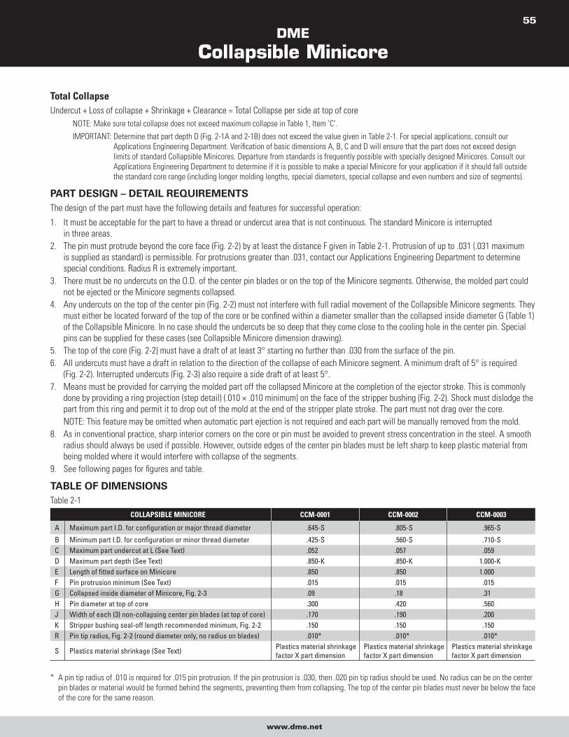
DME
Collapsible Minicore
www.dme.net
55
Total CollapseUndercut + Loss of collapse + Shrinkage + Clearance = Total Collapse per side at top of core
NOTE: Make sure total collapse does not exceed maximum collapse in Table 1, Item ‘C’.
IMPORTANT: Determine that part depth D (Fig. 2-1A and 2-1B) does not exceed the value given in Table 2-1. For special applications, consult our
Applications Engineering Department. Verification of basic dimensions A, B, C and D will ensure that the part does not exceed design
limits of standard Collapsible Minicores. Departure from standards is frequently possible with specially designed Minicores. Consult our
Applications Engineering Department to determine if it is possible to make a special Minicore for your application if it should fall outside
the standard core range (including longer molding lengths, special diameters, special collapse and even numbers and size of segments).
PART DESIGN – DETAIL REQUIREMENTSThe design of the part must have the following details and features for successful operation:
1. It must be acceptable for the part to have a thread or undercut area that is not continuous. The standard Minicore is interrupted
in three areas.
2. The pin must protrude beyond the core face (Fig. 2-2) by at least the distance F given in Table 2-1. Protrusion of up to .031 (.031 maximum
is supplied as standard) is permissible. For protrusions greater than .031, contact our Applications Engineering Department to determine
special conditions. Radius R is extremely important.
3. There must be no undercuts on the O.D. of the center pin blades or on the top of the Minicore segments. Otherwise, the molded part could
not be ejected or the Minicore segments collapsed.
4. Any undercuts on the top of the center pin (Fig. 2-2) must not interfere with full radial movement of the Collapsible Minicore segments. They
must either be located forward of the top of the core or be confined within a diameter smaller than the collapsed inside diameter G (Table 1)
of the Collapsible Minicore. In no case should the undercuts be so deep that they come close to the cooling hole in the center pin. Special
pins can be supplied for these cases (see Collapsible Minicore dimension drawing).
5. The top of the core (Fig. 2-2) must have a draft of at least 3° starting no further than .030 from the surface of the pin.
6. All undercuts must have a draft in relation to the direction of the collapse of each Minicore segment. A minimum draft of 5° is required
(Fig. 2-2). Interrupted undercuts (Fig. 2-3) also require a side draft of at least 5°.
7. Means must be provided for carrying the molded part off the collapsed Minicore at the completion of the ejector stroke. This is commonly
done by providing a ring projection (step detail) (.010 × .010 minimum) on the face of the stripper bushing (Fig. 2-2). Shock must dislodge the
part from this ring and permit it to drop out of the mold at the end of the stripper plate stroke. The part must not drag over the core.
NOTE: This feature may be omitted when automatic part ejection is not required and each part will be manually removed from the mold.
8. As in conventional practice, sharp interior corners on the core or pin must be avoided to prevent stress concentration in the steel. A smooth
radius should always be used if possible. However, outside edges of the center pin blades must be left sharp to keep plastic material from
being molded where it would interfere with collapse of the segments.
9. See following pages for figures and table.
TABLE OF DIMENSIONSTable 2-1
COLLAPSIBLE MINICORE CCM-0001 CCM-0002 CCM-0003
A Maximum part I.D. for configuration or major thread diameter .645-S .805-S .965-S
B Minimum part I.D. for configuration or minor thread diameter .425-S .560-S .710-SC Maximum part undercut at L (See Text) .052 .057 .059D Maximum part depth (See Text) .850-K .850-K 1.000-KE Length of fitted surface on Minicore .850 .850 1.000F Pin protrusion minimum (See Text) .015 .015 .015G Collapsed inside diameter of Minicore, Fig. 2-3 .09 .18 .31H Pin diameter at top of core .300 .420 .560J Width of each (3) non-collapsing center pin blades (at top of core) .170 .190 .200K Stripper bushing seal-off length recommended minimum, Fig. 2-2 .150 .150 .150R Pin tip radius, Fig. 2-2 (round diameter only, no radius on blades) .010* .010* .010*
S Plastics material shrinkage (See Text) Plastics material shrinkage factor X part dimension
Plastics material shrinkage factor X part dimension
Plastics material shrinkage factor X part dimension
* A pin tip radius of .010 is required for .015 pin protrusion. If the pin protrusion is .030, then .020 pin tip radius should be used. No radius can be on the center
pin blades or material would be formed behind the segments, preventing them from collapsing. The top of the center pin blades must never be below the face
of the core for the same reason.
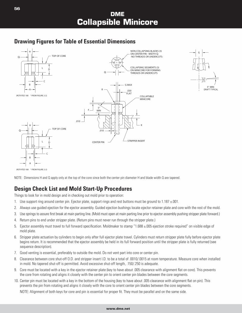
DME
Collapsible Minicore
www.dme.net
56
Drawing Figures for Table of Essential Dimensions
Q
Q
Q
Q
DRAFT TYPICAL
NOTE: Dimensions H and Q apply only at the top of the core since both the center pin diameter H and blade width Q are tapered.
Design Check List and Mold Start-Up ProceduresThings to look for in mold design and in checking out mold prior to operation:
1. Use support ring around center pin. Ejector plate, support rings and rest buttons must be ground to 1.187 ±.001.
2. Always use guided ejection for the ejector assembly. Guided ejection bushings locate ejector retainer plate and core with the rest of the mold.
3. Use springs to assure first break at main parting line. (Mold must open at main parting line prior to ejector assembly pushing stripper plate forward.)
4. Return pins to end under stripper plate. (Return pins must never run through the stripper plate.)
5. Ejector assembly must travel to full forward specification. Moldmaker to stamp “1.688 ±.005 ejection stroke required” on visible edge of
mold plate.
6. Stripper plate actuation by cylinders to begin only after full ejector plate travel. Cylinders must return stripper plate fully before ejector plate
begins return. It is recommended that the ejector assembly be held in its full forward position until the stripper plate is fully returned (see
sequence description).
7. Good venting is essential, preferably to outside the mold. Do not vent part into core or center pin.
8. Clearance between core shut-off O.D. and stripper insert I.D. to be a total of .0010/.0015 at room temperature. Measure core when installed
in mold. No tapered shut-off is permitted. Avoid excessive shut-off length, .150/.250 is adequate.
9. Core must be located with a key in the ejector retainer plate (key to have about .005 clearance with alignment flat on core). This prevents
the core from rotating and aligns it closely with the center pin to orient center pin blades between the core segments.
10. Center pin must be located with a key in the bottom of the housing (key to have about .005 clearance with alignment flat on pin). This
prevents the pin from rotating and aligns it closely with the core to orient center pin blades between the core segments.
NOTE: Alignment of both keys for core and pin is essential for proper fit. They must be parallel and on the same side.
DME
Collapsible Minicore
www.dme.net
57
11. Important: When core and pin are assembled in the mold with 1.562 +.000/-.005 head space dimension, check to make sure that narrow
blades on the center pin are never below the top of the collapsing segments.
NOTE: A recess of the narrow blades below the top of the core segments will result in core damage.
12. Center pin to be concentric with stripper bushing. Verify .015 pin protrusion beyond top of core and a minimum of .010 radius on tip of pin.
Pin tip radius must always be slightly less than the pin protrusion to prevent plastic material from being formed behind the core segments.
No radius is permissible on center pin blades. Examine pins for evidence of any de-temper of pin tip due to overheating in grinding. Water
line bubbler tube in center pin must not throw pin off or cause pin to be improperly mounted.
13. Positive collapse sleeve should travel freely through ‘BX’ support plate. Apply grease lightly to O.D. of positive collapse sleeve. Check for
free movement when the mold is at operating temperature.
14. When top of core segments shut-off against cavity (example, some parts with through holes), all cores must be ground to the same length
(O.A.L.). The normal tolerance of ±.003 is inadequate and may overload core. Refer to “Alterations to Collapsible Minicore” section for core
grinding instructions. Clearance between top of core and cavity to be .0005 to .0010. Do not pre-load core. Whenever the above condition
exists, an early ejector return system is mandatory.
NOTE: This applies only when top of Minicore segments shut off against the cavity. Also, exercise care to avoid pre-load on center pin. A
.0000 to .0015 interference is adequate. Also, whenever above condition exists, the head space dimension in the mold must be held
to exactly what was used to grind the length (O.A.L.) for each core with a tolerance of +.000 to -.001. All cores must be set up for
grinding with exactly the same head space using a tolerance of +.0010 to -.0000. This must be done to prevent the top of the blades
on the center pin from ever falling below the top of the collapsing segments on the core, which would cause serious damage to the
core if it occurred.
15. Check finish on cores:
a. Surface finish and polish must be smooth and allow the segments to collapse freely when plastic material is molded on the core.
b. Undercuts must be in direction of collapse, no back hooks due to improper grinding or design.
c. Proper design procedures must be adhered to.
16. Observe proper care in dry cycling:
a. Plate cocking or bounce should not occur and must be immediately corrected if observed.
b. Audible sounds or visible indications of friction, mis-aligning or scoring must be corrected immediately.
c. Sequence of movements must occur correctly (see Sequence Description).
d. Positive collapse sleeve must move freely and be properly actuated when the ejector assembly is fully forward.
17. Threads ground into Collapsible Minicore should not run out to a feather/knife edge.
Minicore O.D., As Well As Collapsing Segment Thread and Undercut Grinding RecommendationsGENERAL1. Minicore and pin must be cleaned thoroughly prior to assembly for grinding.
2. To assemble Collapsible Minicore for grinding, first align both flats on the heads of the core and pin parallel and on the same side. Then
assemble so that the top of the core and the top of the center pin blades are flush. This will ensure the grinding head space dimension
of 1.562 +.005/-.000 is established. Refer to core dimension and grinding set-up drawings and information for details. Hold this position
by using three set screws near head of core to lock assembly in position during grinding and to true the core on the pin between centers.
Concentricity is extremely important; refer to grinding set-up drawing for details.
NOTE: Cores are factory positioned, but must be reset by grinder because of possible movement in transit.
3. During grinding of core, do not use air blast or water jet at high pressure for cooling, since this may force grinding grit between the
segments.
4. Use a medium grade grinding wheel such as a 32A80.K8VG for core assembly. O.D. of Minicore and center pin blades are of different
Rockwell hardness and materials.
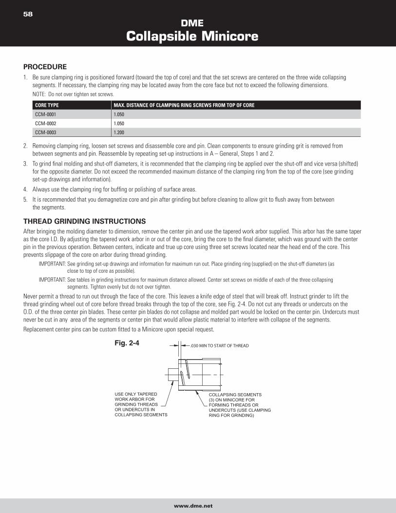
DME
Collapsible Minicore
www.dme.net
58
PROCEDURE1. Be sure clamping ring is positioned forward (toward the top of core) and that the set screws are centered on the three wide collapsing
segments. If necessary, the clamping ring may be located away from the core face but not to exceed the following dimensions.
NOTE: Do not over tighten set screws.
CORE TYPE MAX. DISTANCE OF CLAMPING RING SCREWS FROM TOP OF CORE
CCM-0001 1.050
CCM-0002 1.050
CCM-0003 1.200
2. Removing clamping ring, loosen set screws and disassemble core and pin. Clean components to ensure grinding grit is removed from
between segments and pin. Reassemble by repeating set-up instructions in A – General, Steps 1 and 2.
3. To grind final molding and shut-off diameters, it is recommended that the clamping ring be applied over the shut-off and vice versa (shifted)
for the opposite diameter. Do not exceed the recommended maximum distance of the clamping ring from the top of the core (see grinding
set-up drawings and information).
4. Always use the clamping ring for buffing or polishing of surface areas.
5. It is recommended that you demagnetize core and pin after grinding but before cleaning to allow grit to flush away from between
the segments.
THREAD GRINDING INSTRUCTIONSAfter bringing the molding diameter to dimension, remove the center pin and use the tapered work arbor supplied. This arbor has the same taper
as the core I.D. By adjusting the tapered work arbor in or out of the core, bring the core to the final diameter, which was ground with the center
pin in the previous operation. Between centers, indicate and true up core using three set screws located near the head end of the core. This
prevents slippage of the core on arbor during thread grinding.
IMPORTANT: See grinding set-up drawings and information for maximum run out. Place grinding ring (supplied) on the shut-off diameters (as
close to top of core as possible).
IMPORTANT: See tables in grinding instructions for maximum distance allowed. Center set screws on middle of each of the three collapsing
segments. Tighten evenly but do not over tighten.
Never permit a thread to run out through the face of the core. This leaves a knife edge of steel that will break off. Instruct grinder to lift the
thread grinding wheel out of core before thread breaks through the top of the core, see Fig. 2-4. Do not cut any threads or undercuts on the
O.D. of the three center pin blades. These center pin blades do not collapse and molded part would be locked on the center pin. Undercuts must
never be cut in any area of the segments or center pin that would allow plastic material to interfere with collapse of the segments.
Replacement center pins can be custom fitted to a Minicore upon special request.
COLLAPSING SEGMENTS(3) ON MINICORE FOR FORMING THREADS OR UNDERCUTS (USE CLAMPINGRING FOR GRINDING)
USE ONLY TAPEREDWORK ARBOR FOR GRINDING THREADS OR UNDERCUTS IN COLLAPSING SEGMENTS
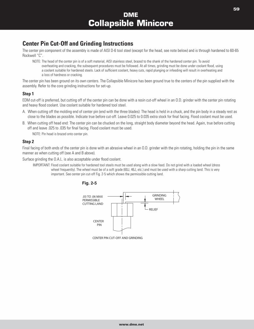
DME
Collapsible Minicore
www.dme.net
59
Center Pin Cut-Off and Grinding InstructionsThe center pin component of the assembly is made of AISI D-6 tool steel (except for the head, see note below) and is through hardened to 60-65
Rockwell “C”.
NOTE: The head of the center pin is of a soft material, AISI stainless steel, brazed to the shank of the hardened center pin. To avoid
overheating and cracking, the subsequent procedures must be followed. At all times, grinding must be done under coolant flood, using
a coolant suitable for hardened steels. Lack of sufficient coolant, heavy cuts, rapid plunging or infeeding will result in overheating and
a loss of hardness or cracking.
The center pin has been ground on its own centers. The Collapsible Minicore has been ground true to the centers of the pin supplied with the
assembly. Refer to the core grinding instructions for set-up.
Step 1EDM cut-off is preferred, but cutting off of the center pin can be done with a resin cut-off wheel in an O.D. grinder with the center pin rotating
and heavy flood coolant. Use coolant suitable for hardened tool steel.
A. When cutting off the molding end of center pin (end with the three blades): The head is held in a chuck, and the pin body in a steady rest as
close to the blades as possible. Indicate true before cut-off. Leave 0.025 to 0.035 extra stock for final facing. Flood coolant must be used.
B. When cutting off head end: The center pin can be chucked on the long, straight body diameter beyond the head. Again, true before cutting
off and leave .025 to .035 for final facing. Flood coolant must be used.
NOTE: Pin head is brazed onto center pin.
Step 2Final facing of both ends of the center pin is done with an abrasive wheel in an O.D. grinder with the pin rotating, holding the pin in the same
manner as when cutting off (see A and B above).
Surface grinding the O.A.L. is also acceptable under flood coolant.
IMPORTANT: Flood coolant suitable for hardened tool steels must be used along with a slow feed. Do not grind with a loaded wheel (dress
wheel frequently). The wheel must be of a soft grade (60J, 46J, etc.) and must be used with a sharp cutting land. This is very
important. See center pin cut-off Fig. 2-5 which shows the permissible cutting land.

DME
Collapsible Minicore
www.dme.net
60
Alterations to Collapsible MinicoresIN SHORTENING THE LENGTH (O.A.L.) OF A MINICORE, THE FOLLOWING PROCEDURE MUST BE USED:First, the Minicore should be removed from its original center pin and the core thoroughly cleaned. The core is then placed on the tapered
work arbor supplied with the Minicore for grinding. The work arbor has a taper ground on the front end that matches the Minicore I.D. and has
centers both front and rear. Insert the tapered end of the work arbor into the Collapsible Minicore until the diameter of the Minicore, when
measured over the positive collapse bumps, coincides with this diameter as measured while the Minicore is on its own center pin with the
specified grinding head space dimension of 1.562 +.005/-.000.
When using a work arbor (with no head or blades) or even a special work center pin (with head and blades), do not attempt to locate the
Minicore for grinding by setting its standard grinding head space. This will almost never be the correct setting for the Minicore since each core
is individually custom fitted with a specific pin. If a special work pin is used with an alignment flat on its head, it must be oriented parallel to
and on the same side as alignment flat on core.
To shorten the Minicore to a new length, the core is fixtured to the arbor using three set screws near the head of the core. The three collapsing
segments must be held rigidly under a clamping ring located near the top of the core. See grinding set-up drawing for additional information.
Then material is removed from the top (front) of the Minicore on a cylindrical grinder. The grinding wheel goes through the entire material of the
Minicore segments and cuts into the arbor to ensure a clean front surface. Remove burrs carefully but do not break any sharp corners, which
would allow plastic material to form where it would interfere with collapse of the segments.The Minicores collapse per side will be reduced by
.020 in./in. x amount Minicore is shortened.
It is now obvious why an arbor or special work center pin is used. If this grinding was performed on the Minicore’s regular center pin, the taper
would be destroyed.
When a Minicore has to be reground after its thread profiles have been finished and the centers on the regular pin have been removed, again an arbor or special center pin is used.The tapered end of the work arbor is inserted into the Minicore until the ground diameters of the Minicore coincide with those measured on
the core with its regular center pin. The Minicore is fixtured on the work arbor with set screws and clamping ring as described above. It is now
possible to change the diameters on the molding end of the Minicore segments, or to deepen or enlarge the thread profiles. If alterations are
required that affect the O.D. of the center pin blades, a new custom fitted center pin may be required so that centers can be used to grind the
Minicore and center pin uniformly.
After all finish grinding and polishing operations on the Minicore, it is important to demagnetize the core to prevent the adhesion of any metal
particles that might find their way into cavities during molding.
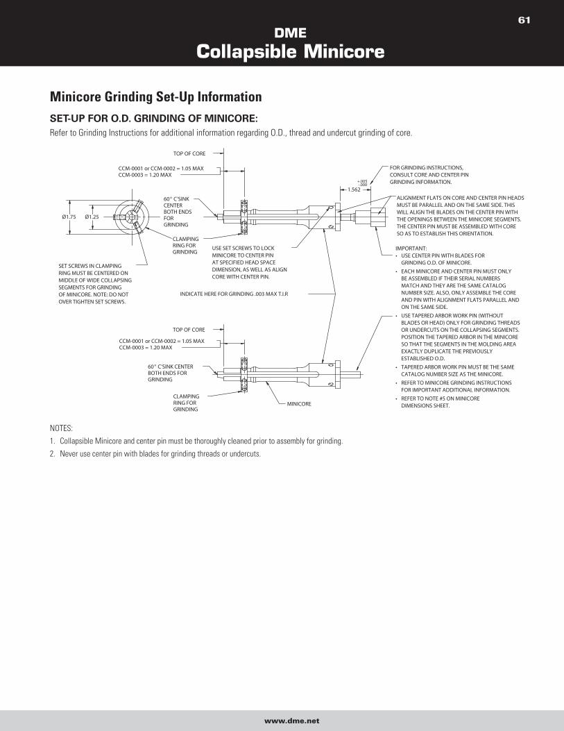
DME
Collapsible Minicore
www.dme.net
61
Minicore Grinding Set-Up InformationSET-UP FOR O.D. GRINDING OF MINICORE: Refer to Grinding Instructions for additional information regarding O.D., thread and undercut grinding of core.
NOTES:
1. Collapsible Minicore and center pin must be thoroughly cleaned prior to assembly for grinding.
2. Never use center pin with blades for grinding threads or undercuts.
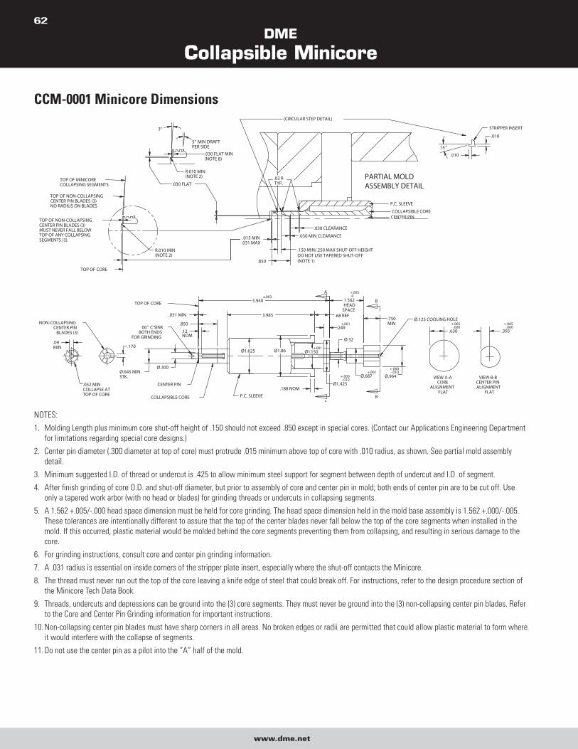
DME
Collapsible Minicore
www.dme.net
62
CCM-0001 Minicore Dimensions
NOTES:
1. Molding Length plus minimum core shut-off height of .150 should not exceed .850 except in special cores. (Contact our Applications Engineering Department
for limitations regarding special core designs.)
2. Center pin diameter (.300 diameter at top of core) must protrude .015 minimum above top of core with .010 radius, as shown. See partial mold assembly
detail.
3. Minimum suggested I.D. of thread or undercut is .425 to allow minimum steel support for segment between depth of undercut and I.D. of segment.
4. After finish grinding of core O.D. and shut-off diameter, but prior to assembly of core and center pin in mold; both ends of center pin are to be cut off. Use
only a tapered work arbor (with no head or blades) for grinding threads or undercuts in collapsing segments.
5. A 1.562 +.005/-.000 head space dimension must be held for core grinding. The head space dimension held in the mold base assembly is 1.562 +.000/-.005.
These tolerances are intentionally different to assure that the top of the center blades never fall below the top of the core segments when installed in the
mold. If this occurred, plastic material would be molded behind the core segments preventing them from collapsing, and resulting in serious damage to the
core.
6. For grinding instructions, consult core and center pin grinding information.
7. A .031 radius is essential on inside corners of the stripper plate insert, especially where the shut-off contacts the Minicore.
8. The thread must never run out the top of the core leaving a knife edge of steel that could break off. For instructions, refer to the design procedure section of
the Minicore Tech Data Book.
9. Threads, undercuts and depressions can be ground into the (3) core segments. They must never be ground into the (3) non-collapsing center pin blades. Refer
to the Core and Center Pin Grinding information for important instructions.
10. Non-collapsing center pin blades must have sharp corners in all areas. No broken edges or radii are permitted that could allow plastic material to form where
it would interfere with the collapse of segments.
11. Do not use the center pin as a pilot into the “A” half of the mold.
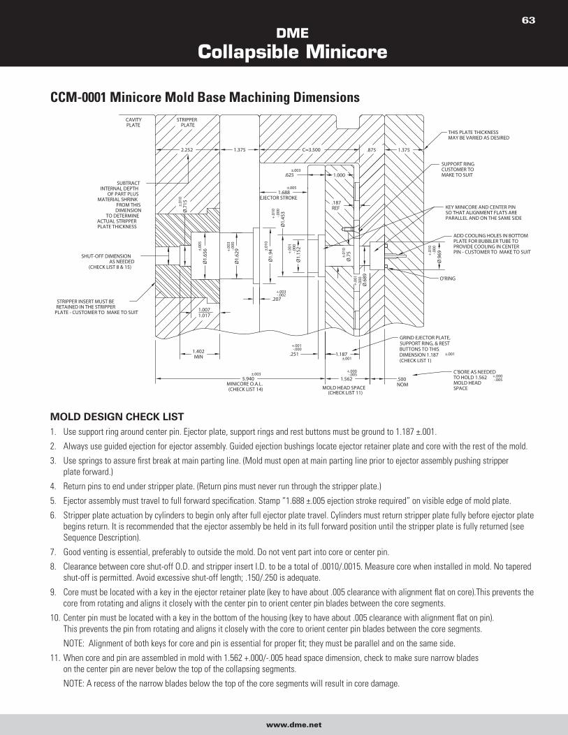
DME
Collapsible Minicore
www.dme.net
63
CCM-0001 Minicore Mold Base Machining Dimensions
MOLD DESIGN CHECK LIST 1. Use support ring around center pin. Ejector plate, support rings and rest buttons must be ground to 1.187 ±.001.
2. Always use guided ejection for ejector assembly. Guided ejection bushings locate ejector retainer plate and core with the rest of the mold.
3. Use springs to assure first break at main parting line. (Mold must open at main parting line prior to ejector assembly pushing stripper
plate forward.)
4. Return pins to end under stripper plate. (Return pins must never run through the stripper plate.)
5. Ejector assembly must travel to full forward specification. Stamp “1.688 ±.005 ejection stroke required” on visible edge of mold plate.
6. Stripper plate actuation by cylinders to begin only after full ejector plate travel. Cylinders must return stripper plate fully before ejector plate
begins return. It is recommended that the ejector assembly be held in its full forward position until the stripper plate is fully returned (see
Sequence Description).
7. Good venting is essential, preferably to outside the mold. Do not vent part into core or center pin.
8. Clearance between core shut-off O.D. and stripper insert I.D. to be a total of .0010/.0015. Measure core when installed in mold. No tapered
shut-off is permitted. Avoid excessive shut-off length; .150/.250 is adequate.
9. Core must be located with a key in the ejector retainer plate (key to have about .005 clearance with alignment flat on core).This prevents the
core from rotating and aligns it closely with the center pin to orient center pin blades between the core segments.
10. Center pin must be located with a key in the bottom of the housing (key to have about .005 clearance with alignment flat on pin).
This prevents the pin from rotating and aligns it closely with the core to orient center pin blades between the core segments.
NOTE: Alignment of both keys for core and pin is essential for proper fit; they must be parallel and on the same side.
11. When core and pin are assembled in mold with 1.562 +.000/-.005 head space dimension, check to make sure narrow blades
on the center pin are never below the top of the collapsing segments.
NOTE: A recess of the narrow blades below the top of the core segments will result in core damage.
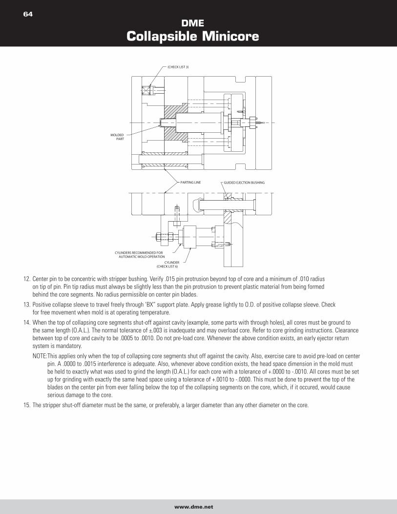
DME
Collapsible Minicore
www.dme.net
64
12. Center pin to be concentric with stripper bushing. Verify .015 pin protrusion beyond top of core and a minimum of .010 radius
on tip of pin. Pin tip radius must always be slightly less than the pin protrusion to prevent plastic material from being formed
behind the core segments. No radius permissible on center pin blades.
13. Positive collapse sleeve to travel freely through ‘BX” support plate. Apply grease lightly to O.D. of positive collapse sleeve. Check
for free movement when mold is at operating temperature.
14. When the top of collapsing core segments shut-off against cavity (example, some parts with through holes), all cores must be ground to
the same length (O.A.L.). The normal tolerance of ±.003 is inadequate and may overload core. Refer to core grinding instructions. Clearance
between top of core and cavity to be .0005 to .0010. Do not pre-load core. Whenever the above condition exists, an early ejector return
system is mandatory.
NOTE: This applies only when the top of collapsing core segments shut off against the cavity. Also, exercise care to avoid pre-load on center
pin. A .0000 to .0015 interference is adequate. Also, whenever above condition exists, the head space dimension in the mold must
be held to exactly what was used to grind the length (O.A.L.) for each core with a tolerance of +.0000 to -.0010. All cores must be set
up for grinding with exactly the same head space using a tolerance of +.0010 to -.0000. This must be done to prevent the top of the
blades on the center pin from ever falling below the top of the collapsing segments on the core, which, if it occured, would cause
serious damage to the core.
15. The stripper shut-off diameter must be the same, or preferably, a larger diameter than any other diameter on the core.
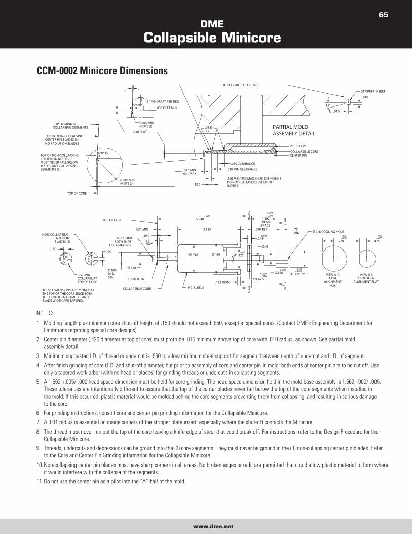
DME
Collapsible Minicore
www.dme.net
65
CCM-0002 Minicore Dimensions
NOTES:
1. Molding length plus minimum core shut-off height of .150 should not exceed .850, except in special cores. (Contact DME’s Engineering Department for
limitations regarding special core designs).
2. Center pin diameter (.420 diameter at top of core) must protrude .015 minimum above top of core with .010 radius, as shown. See partial mold
assembly detail.
3. Minimum suggested I.D. of thread or undercut is .560 to allow minimum steel support for segment between depth of undercut and I.D. of segment.
4. After finish grinding of core O.D. and shut-off diameter, but prior to assembly of core and center pin in mold; both ends of center pin are to be cut off. Use
only a tapered work arbor (with no head or blades) for grinding threads or undercuts in collapsing segments.
5. A 1.562 +.005/-.000 head space dimension must be held for core grinding. The head space dimension held in the mold base assembly is 1.562 +000/-.005.
These tolerances are intentionally different to assure that the top of the center blades never fall below the top of the core segments when installed in
the mold. If this occurred, plastic material would be molded behind the core segments preventing them from collapsing, and resulting in serious damage
to the core.
6. For grinding instructions, consult core and center pin grinding information for the Collapsible Minicore.
7. A .031 radius is essential on inside corners of the stripper plate insert; especially where the shut-off contacts the Minicore.
8. The thread must never run out the top of the core leaving a knife edge of steel that could break off. For instructions, refer to the Design Procedure for the
Collapsible Minicore.
9. Threads, undercuts and depressions can be ground into the (3) core segments. They must never be ground in the (3) non-collapsing center pin blades. Refer
to the Core and Center Pin Grinding information for the Collapsible Minicore.
10. Non-collapsing center pin blades must have sharp corners in all areas. No broken edges or radii are permitted that could allow plastic material to form where
it would interfere with the collapse of the segments.
11. Do not use the center pin as a pilot into the “A” half of the mold.
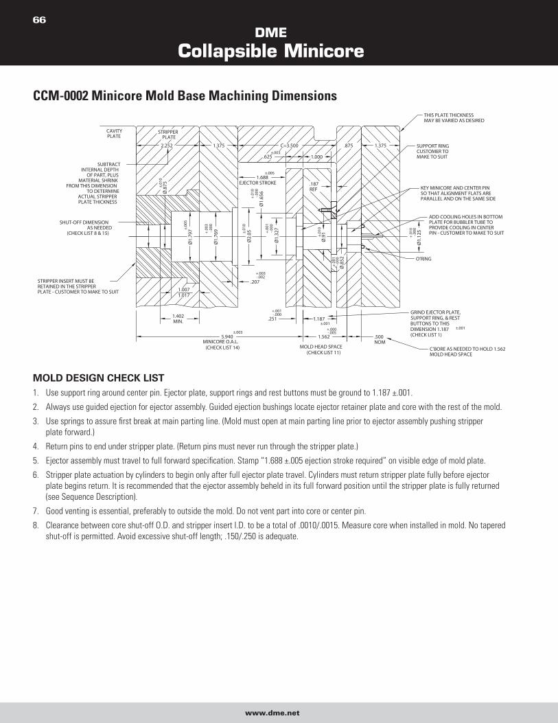
DME
Collapsible Minicore
www.dme.net
66
CCM-0002 Minicore Mold Base Machining Dimensions
MOLD DESIGN CHECK LIST 1. Use support ring around center pin. Ejector plate, support rings and rest buttons must be ground to 1.187 ±.001.
2. Always use guided ejection for ejector assembly. Guided ejection bushings locate ejector retainer plate and core with the rest of the mold.
3. Use springs to assure first break at main parting line. (Mold must open at main parting line prior to ejector assembly pushing stripper
plate forward.)
4. Return pins to end under stripper plate. (Return pins must never run through the stripper plate.)
5. Ejector assembly must travel to full forward specification. Stamp “1.688 ±.005 ejection stroke required” on visible edge of mold plate.
6. Stripper plate actuation by cylinders to begin only after full ejector plate travel. Cylinders must return stripper plate fully before ejector
plate begins return. It is recommended that the ejector assembly beheld in its full forward position until the stripper plate is fully returned
(see Sequence Description).
7. Good venting is essential, preferably to outside the mold. Do not vent part into core or center pin.
8. Clearance between core shut-off O.D. and stripper insert I.D. to be a total of .0010/.0015. Measure core when installed in mold. No tapered
shut-off is permitted. Avoid excessive shut-off length; .150/.250 is adequate.
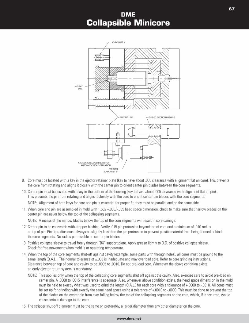
DME
Collapsible Minicore
www.dme.net
67
9. Core must be located with a key in the ejector retainer plate (key to have about .005 clearance with alignment flat on core). This prevents
the core from rotating and aligns it closely with the center pin to orient center pin blades between the core segments.
10. Center pin must be located with a key in the bottom of the housing (key to have about .005 clearance with alignment flat on pin).
This prevents the pin from rotating and aligns it closely with the core to orient center pin blades with the core segments.
NOTE: Alignment of both keys for core and pin is essential for proper fit, they must be parallel and on the same side.
11. When core and pin are assembled in mold with 1.562 +.000/-.005 head space dimension, check to make sure that narrow blades on the
center pin are never below the top of the collapsing segments.
NOTE: A recess of the narrow blades below the top of the core segments will result in core damage.
12. Center pin to be concentric with stripper bushing. Verify .015 pin protrusion beyond top of core and a minimum of .010 radius
on tip of pin. Pin tip radius must always be slightly less than the pin protrusion to prevent plastic material from being formed behind
the core segments. No radius permissible on center pin blades.
13. Positive collapse sleeve to travel freely through “BX” support plate. Apply grease lightly to O.D. of positive collapse sleeve.
Check for free movement when mold is at operating temperature.
14. When the top of the core segments shut-off against cavity (example, some parts with through holes), all cores must be ground to the
same length (O.A.L.). The normal tolerance of ±.003 is inadequate and may overload core. Refer to core grinding instructions.
Clearance between top of core and cavity to be .0005 to .0010. Do not pre-load core. Whenever the above condition exists,
an early ejector return system is mandatory.
NOTE: This applies only when the top of the collapsing core segments shut off against the cavity. Also, exercise care to avoid pre-load on
center pin. A .0000 to .0015 interference is adequate. Also, whenever above condition exists, the head space dimension in the mold
must be held to exactly what was used to grind the length (O.A.L.) for each core with a tolerance of +.0000 to -.0010. All cores must
be set up for grinding with exactly the same head space using a tolerance of +.0010 to -.0000. This must be done to prevent the top
of the blades on the center pin from ever falling below the top of the collapsing segments on the core, which, if it occurred, would
cause serious damage to the core.
15. The stripper shut-off diameter must be the same or, preferably, a larger diameter than any other diameter on the core.
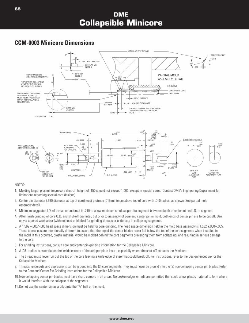
DME
Collapsible Minicore
www.dme.net
68
CCM-0003 Minicore Dimensions
NOTES:
1. Molding length plus minimum core shut-off height of .150 should not exceed 1.000, except in special cores. (Contact DME’s Engineering Department for
limitations regarding special core designs).
2. Center pin diameter (.560 diameter at top of core) must protrude .015 minimum above top of core with .010 radius, as shown. See partial mold
assembly detail.
3. Minimum suggested I.D. of thread or undercut is .710 to allow minimum steel support for segment between depth of undercut and I.D. of segment.
4. After finish grinding of core O.D. and shut-off diameter, but prior to assembly of core and center pin in mold, both ends of center pin are to be cut off. Use
only a tapered work arbor (with no head or blades) for grinding threads or undercuts in collapsing segments.
5. A 1.562 +.005/-.000 head space dimension must be held for core grinding. The head space dimension held in the mold base assembly is 1.562 +.000/-.005.
These tolerances are intentionally different to assure that the top of the center blades never fall below the top of the core segments when installed in
the mold. If this occurred, plastic material would be molded behind the core segments preventing them from collapsing, and resulting in serious damage
to the core.
6. For grinding instructions, consult core and center pin grinding information for the Collapsible Minicore.
7. A .031 radius is essential on the inside corners of the stripper plate insert, especially where the shut-off contacts the Minicore.
8. The thread must never run out the top of the core leaving a knife edge of steel that could break off. For instructions, refer to the Design Procedure for the
Collapsible Minicore.
9. Threads, undercuts and depressions can be ground into the (3) core segments. They must never be ground into the (3) non-collapsing center pin blades. Refer
to the Core and Center Pin Grinding instructions for the Collapsible Minicore.
10. Non-collapsing center pin blades must have sharp corners in all areas. No broken edges or radii are permitted that could allow plastic material to form where
it would interfere with the collapse of the segments.
11. Do not use the center pin as a pilot into the “A” half of the mold.
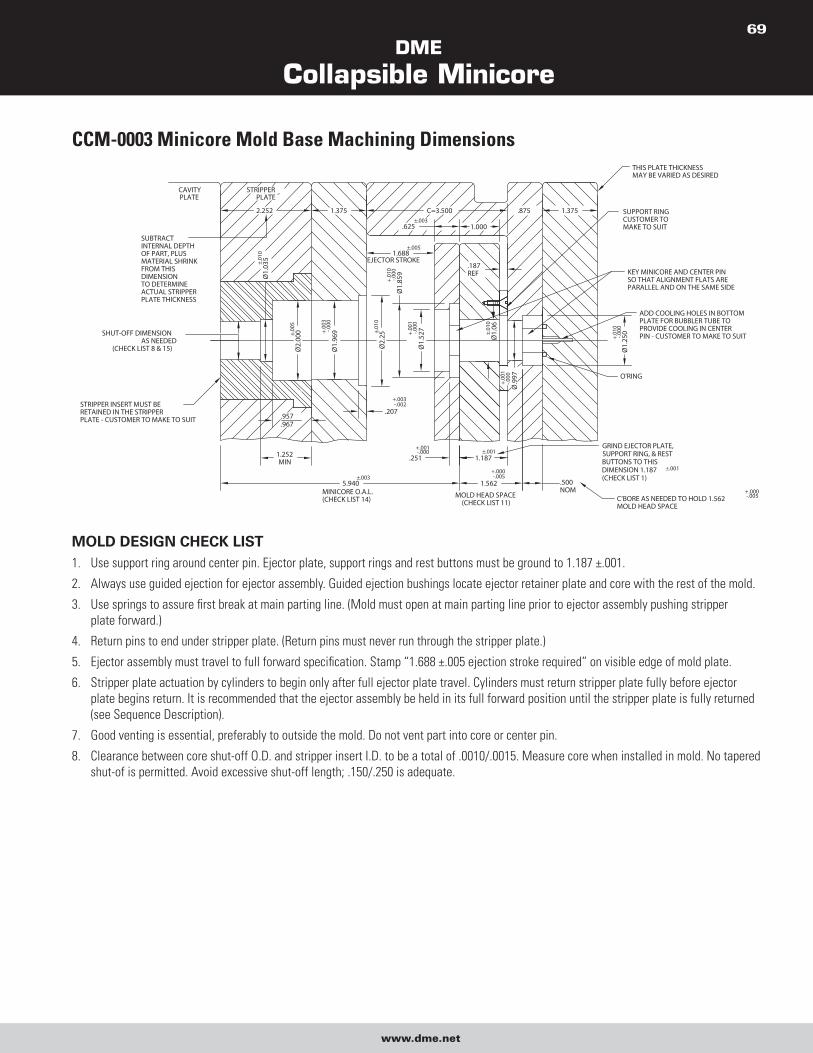
DME
Collapsible Minicore
www.dme.net
69
CCM-0003 Minicore Mold Base Machining Dimensions
MOLD DESIGN CHECK LIST 1. Use support ring around center pin. Ejector plate, support rings and rest buttons must be ground to 1.187 ±.001.
2. Always use guided ejection for ejector assembly. Guided ejection bushings locate ejector retainer plate and core with the rest of the mold.
3. Use springs to assure first break at main parting line. (Mold must open at main parting line prior to ejector assembly pushing stripper
plate forward.)
4. Return pins to end under stripper plate. (Return pins must never run through the stripper plate.)
5. Ejector assembly must travel to full forward specification. Stamp “1.688 ±.005 ejection stroke required” on visible edge of mold plate.
6. Stripper plate actuation by cylinders to begin only after full ejector plate travel. Cylinders must return stripper plate fully before ejector
plate begins return. It is recommended that the ejector assembly be held in its full forward position until the stripper plate is fully returned
(see Sequence Description).
7. Good venting is essential, preferably to outside the mold. Do not vent part into core or center pin.
8. Clearance between core shut-off O.D. and stripper insert I.D. to be a total of .0010/.0015. Measure core when installed in mold. No tapered
shut-of is permitted. Avoid excessive shut-off length; .150/.250 is adequate.
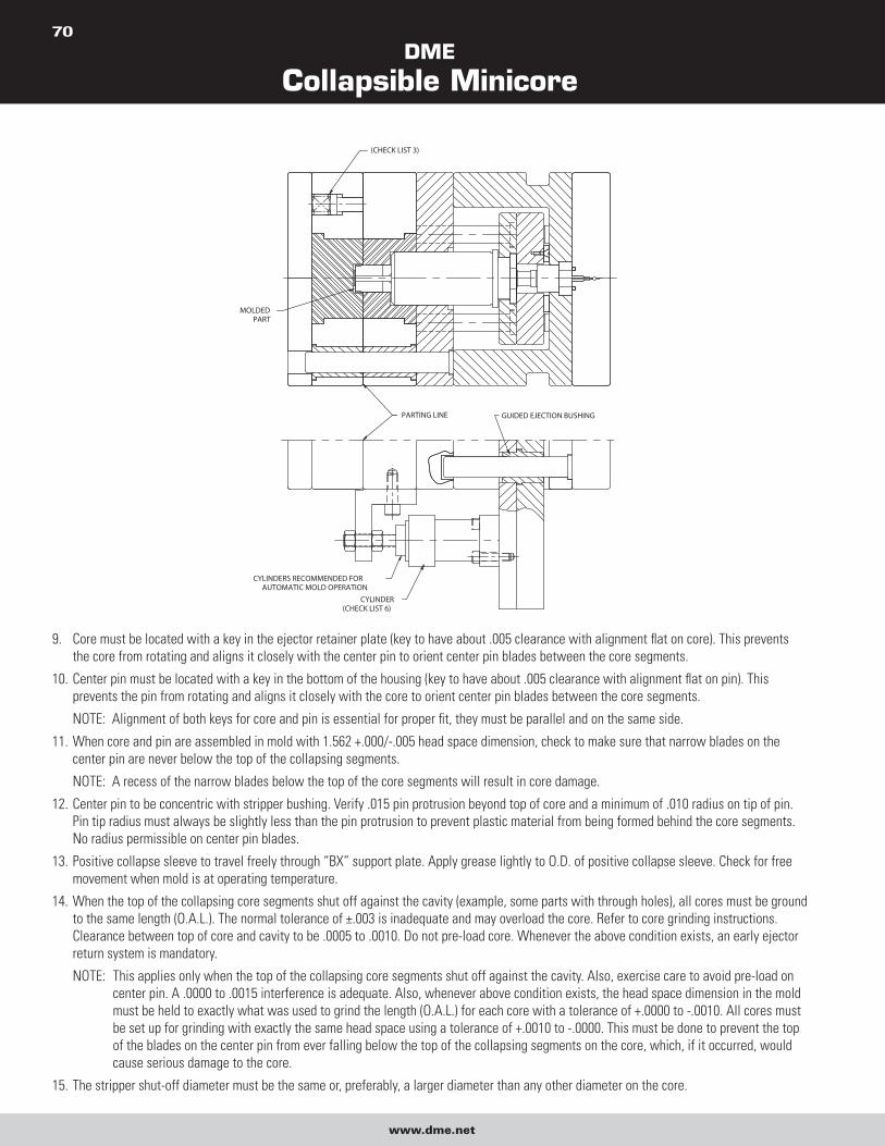
DME
Collapsible Minicore
www.dme.net
70
9. Core must be located with a key in the ejector retainer plate (key to have about .005 clearance with alignment flat on core). This prevents
the core from rotating and aligns it closely with the center pin to orient center pin blades between the core segments.
10. Center pin must be located with a key in the bottom of the housing (key to have about .005 clearance with alignment flat on pin). This
prevents the pin from rotating and aligns it closely with the core to orient center pin blades between the core segments.
NOTE: Alignment of both keys for core and pin is essential for proper fit, they must be parallel and on the same side.
11. When core and pin are assembled in mold with 1.562 +.000/-.005 head space dimension, check to make sure that narrow blades on the
center pin are never below the top of the collapsing segments.
NOTE: A recess of the narrow blades below the top of the core segments will result in core damage.
12. Center pin to be concentric with stripper bushing. Verify .015 pin protrusion beyond top of core and a minimum of .010 radius on tip of pin.
Pin tip radius must always be slightly less than the pin protrusion to prevent plastic material from being formed behind the core segments.
No radius permissible on center pin blades.
13. Positive collapse sleeve to travel freely through “BX” support plate. Apply grease lightly to O.D. of positive collapse sleeve. Check for free
movement when mold is at operating temperature.
14. When the top of the collapsing core segments shut off against the cavity (example, some parts with through holes), all cores must be ground
to the same length (O.A.L.). The normal tolerance of ±.003 is inadequate and may overload the core. Refer to core grinding instructions.
Clearance between top of core and cavity to be .0005 to .0010. Do not pre-load core. Whenever the above condition exists, an early ejector
return system is mandatory.
NOTE: This applies only when the top of the collapsing core segments shut off against the cavity. Also, exercise care to avoid pre-load on
center pin. A .0000 to .0015 interference is adequate. Also, whenever above condition exists, the head space dimension in the mold
must be held to exactly what was used to grind the length (O.A.L.) for each core with a tolerance of +.0000 to -.0010. All cores must
be set up for grinding with exactly the same head space using a tolerance of +.0010 to -.0000. This must be done to prevent the top
of the blades on the center pin from ever falling below the top of the collapsing segments on the core, which, if it occurred, would
cause serious damage to the core.
15. The stripper shut-off diameter must be the same or, preferably, a larger diameter than any other diameter on the core.
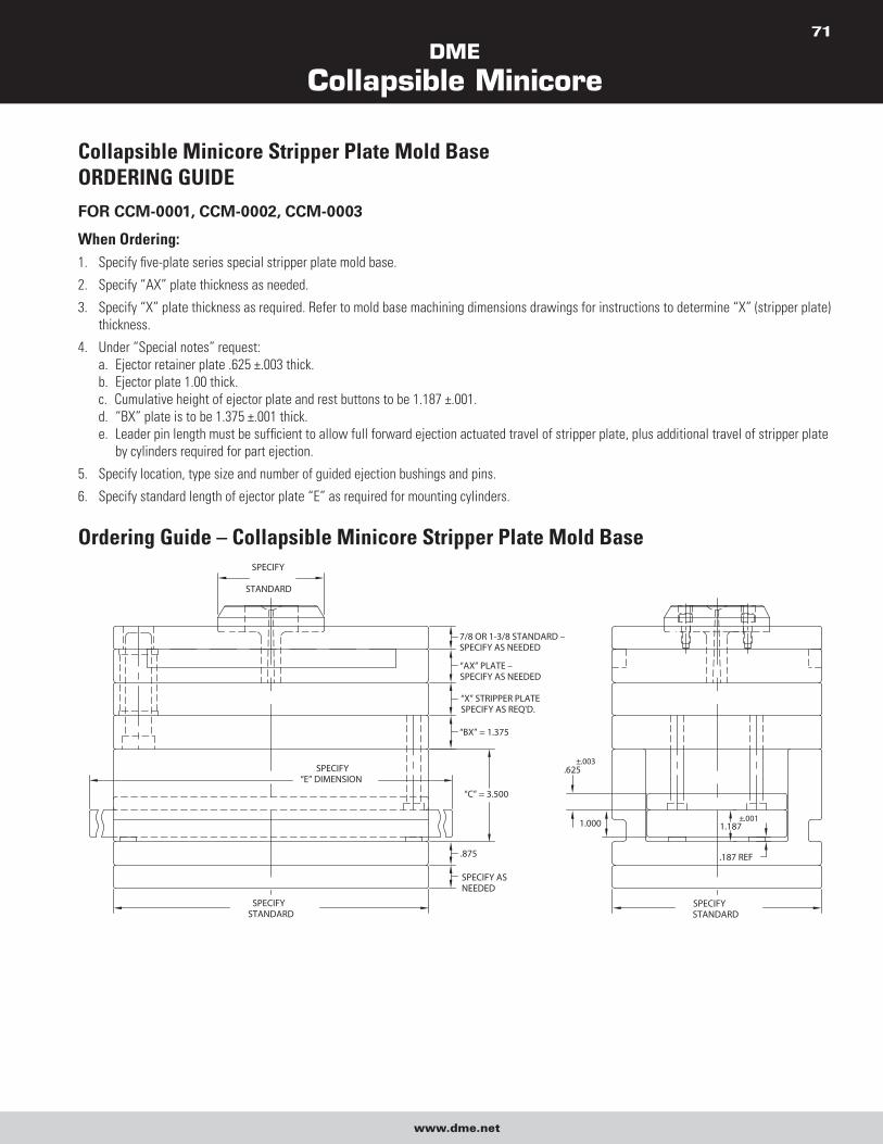
DME
Collapsible Minicore
www.dme.net
71
Collapsible Minicore Stripper Plate Mold BaseORDERING GUIDEFOR CCM-0001, CCM-0002, CCM-0003
When Ordering: 1. Specify five-plate series special stripper plate mold base.
2. Specify “AX” plate thickness as needed.
3. Specify “X” plate thickness as required. Refer to mold base machining dimensions drawings for instructions to determine “X” (stripper plate)
thickness.
4. Under “Special notes” request:
a. Ejector retainer plate .625 ±.003 thick.
b. Ejector plate 1.00 thick.
c. Cumulative height of ejector plate and rest buttons to be 1.187 ±.001.
d. “BX” plate is to be 1.375 ±.001 thick.
e. Leader pin length must be sufficient to allow full forward ejection actuated travel of stripper plate, plus additional travel of stripper plate
by cylinders required for part ejection.
5. Specify location, type size and number of guided ejection bushings and pins.
6. Specify standard length of ejector plate “E” as required for mounting cylinders.
Ordering Guide – Collapsible Minicore Stripper Plate Mold Base

U.S. 800-626-6653 � Canada 800-387-6600 � www.dme.net
World Headquarters DME Company LLC29111 Stephenson Highway
Madison Heights, MI 48071
800-626-6653 toll-free tel 248-398-6000 tel 888-808-4363 toll-free fax www.dme.net web [email protected] e-mail
DME of Canada Ltd.6210 Northwest Drive
Mississauga, Ontario
Canada L4V 1J6
800-387-6600 toll-free tel 905-677-6370 tel 800-461-9965 toll-free fax [email protected] e-mail
DME EuropeDME Belgium C.V.B.A.
Industriepark Noord
B-2800 Mechelen
Belgium
32-15-215011 tel 32-15-218235 fax [email protected] e-mail
CC-MCC DAG 11/12