Embed Size (px)
Citation preview

Collision Reconstruction Methodologies
Volume 1: Collision Documentation
Warrendale, Pennsylvania, USA
v©2019 SAE International
contents
Introduction xiii
C H A P T E R 1
A Video Tracking Photogrammetry Technique to Survey Roadways for Accident Reconstruction 1
Background 1Introduction 2Video Tracking Photogrammetry 4
Scene Surveying 4
Setting Up the Video Take 5
Taking the Video 5
Tips 5
Processing the Data 6
Case Studies 7Flat Highway 7
Road Signs and Telephone Poles 7
Rolling Highway 9
Comparison of Survey Accuracy for Road Curvature 12
Comparison of Survey Accuracy for Road Profile 12
Residential Roads 12
Future Development 12Conclusion 14References 14
C H A P T E R 2
A Three-Dimensional Crush Measurement Methodology Using Two-Dimensional Photographs 15
Introduction 15Previous Research Studies 16Methodology 17
vi Contents
Procedure 18Step One: Photograph Selection 18
Step Two (Part One): Wireframe Model Acquisition 19
Step Two (Part Two): Model/Photograph Alignment 19
Step Three: Vertices Displacement (“Deforming” The Model) 20
Selected Case Studies 20Case Study No. 1 20
Methodology 20
Case Study No. 1 Results 22
Case Study No. 2 22
Methodology 23
Case Study No. 2 Results 24
Discussion 24Conclusion 25Acknowledgments 25References 26Appendix A. Case Study No. 1: Comparison of Crush Measurements Using Various Methodologies 29Appendix B. Case Study No. 2: Comparison of Crush Measurements Using Various Methodologies 30
C H A P T E R 3
Using Particle Image Velocimetry for Road Vehicle Tracking and Performance Monitoring 31
Introduction 32Purpose 32
Background 32
Literature Review 33
Overview 34
Mathematical Basis for DPIV 34Description of Vehicle Kinematics 36Preliminary Testing 38Bounds of Performance 39Experimental Procedures 40
Description of Systems 40
Calibration 40
Modifications to OpenPIV 40
Data Collection 40
Straight-Line Driving Test Results 41
Contents vii
Analysis of Data 42Omission of Outliers 42
Least Squares Analysis 43
Comparison of Analysis Techniques 44
Sources of Uncertainty 44Conclusions 45References 45
C H A P T E R 4
Benefits and Methodology for Dimensioning a Vehicle Using a 3D Scanner for Accident Reconstruction Purposes 47
Introduction 48Methodology for Dimensioning a Vehicle 49
Scanner Setup Prior to Inspection Trip 49
Scanner Setup at Inspection 50
Scanning a Vehicle 51
Post Processing the Scanner Data 52
Reconstruction Case Studies 55Case 1: A Roof Deformation Case on a Small Sport Utility Vehicle 55
Case 2: Collision Between a Motorcycle and Towed Trailer 56
Case 3: Intersectional Collision Case Involving Two Vehicles 57
Case 4: Damage Documentation on a UTV 59
Case 5: Seat Belt and Seat Movement Investigation 60
Discussion 60Conclusions 61References 62Acknowledgments 62
C H A P T E R 5
The Accuracy of Photo-Based Three-Dimensional Scanning for Collision Reconstruction Using 123D Catch 63
Introduction 64Crush Jigs 64
Plumb Line Tracing 64
viii Contents
Total Station Survey 64
Laser Scanning 65
Coordinate Measuring Machines 65
Traditional Photogrammetry 65
Photo-Based 3D Scanning 66
Photo-Based 3D Scanning Theory 66
Photo-Based 3D Scanning Software 67
Purpose 67
Method 67Vehicle Preparation 67
Total Station Measurements 69
Traditional Photogrammetry Measurements 69
Photo-Based 3D Scanning 70
Data Analysis 71
Results 72Comparison between Total Station and Photo-Based 3D Scanning 72
Comparison between Traditional Photogrammetry and Photo-Based 3D Scanning 72
Discussion 73Measurement Deviation 73
Strengths of Photo-Based 3D Scanning 73
Limitations of Photo-Based 3D Scanning 74
Summary/Conclusions 75References 75
C H A P T E R 6
Applying Camera Matching Methods to Laser-Scanned Three-Dimensional Scene Data with Comparisons to Other Methods 79
Introduction 80Photogrammetry Methods Used 81
Photogrammetry Software 81
Photogrammetry Using Point Cloud Data 82
Photograph Rectification of Point Cloud Data 83
Camera Matching to Point Cloud Data 83
Photogrammetry Using 3D Scanner Data 84The Method of Virtual Camera Matching to a Scene 84
Applying the Virtual Camera Matching Method to a Complex Crash on Sloped Terrain 87
Accuracy Comparison for the Staged Collision 89

Contents ix
Photograph Considerations for Camera Matching Photogrammetry 93Summary/Conclusions 94References 95Acknowledgments 95Appendix 96
C H A P T E R 7
Assessment of the Accuracy of Google Earth Imagery for Use as a Tool in Accident Reconstruction 107
Introduction 108Methodology 109Results 114Discussion 116Summary/Conclusions 117References 118Acknowledgments 118Appendix 119
C H A P T E R 8
A Quantitative Method for Accurately Depicting Still Photographs or Video of a Nighttime Scene Utilizing Equivalent Contrast 131
Introduction 132Contrast 133
Prior Methodologies 133
Methodology 134Overview 134
Testing 134
Results 136Calibrating for an Object that cannot be Seen 136
Calibrating for an Object that can be Seen 137
Discussion 138Conclusions 139
x Contents
References 140Conflict of Interest Statement 140
C H A P T E R 9
Evaluation of the Accuracy of Image-Based Scanning as a Basis for Photogrammetric Reconstruction of Physical Evidence 141
Introduction 142Underlying Concepts—Image-Based Scanning 143Advantages of Unmanned Aerial Vehicles 144Methodology 144Results 147Discussion and Conclusions 152References 152Appendix 154
Appendix A—Images of Photogrammetric Process 154
Appendix B—Comparison of Individual Reconstructed Points to FARO Scan Data 161
C H A P T E R 1 0
A Survey of Multiview Photogrammetry Software for Documenting Vehicle Crush 163
Introduction 164Methodology 165
3D Scanner Documentation 165
Photograph and Video Documentation 166
Photogrammetry Software 167
3D Scan Data Processing 168
Photogrammetric Data Processing 168
Scaling and Comparing the Point Clouds 169
Results 174Initial Software Evaluation 174
Camera Comparison 176
Photographs and Video Comparison 179
Software Evaluation Using Limited Photographs 181
Damaged and Undamaged Vehicle Comparison 184
Further Analysis: Photographs and Video Comparison 187

Contents xi
Summary/Conclusions 189References 191Acknowledgments 193Appendix 194
Appendix A Complete Photograph Sets by Camera 194
Appendix B Histograms of Photogrammetry Software Data Distance from LiDAR Data 202
Appendix C Histograms of Camera-Specific Photogrammetry Software Data Distance from LiDAR Data 204
Appendix D Histograms of Video-Based Photogrammetry Software Data Distance from LiDAR Data 206
Appendix E Histograms of Specific Photograph Amounts—Photogrammetry Software Data Distance from LiDAR Data 208
About the Author 211

Collision Reconstruction Methodologies
Volume 2: Night Vision Study
Warrendale, Pennsylvania, USA
v©2019 SAE International
contents
Introduction ix
C H A P T E R 1
Threshold Visibility Levels for the Adrian Visibility Model under Nighttime Driving Conditions 1
Introduction 1Methods 2
Data/Model Integration 2
Analysis 5
Results 6Discussion 9Conclusion 11References 11
C H A P T E R 2
Validation of Digital Image Representations of Low-Illumination Scenes 13
Introduction 13Low-Illumination Photography Methods 14Methods 17
Overview 17
Scene SetUp 17
Camera 17
Images 18
Contrast Charts 18
Displays and Printer 19
Calibrating the Display Devices 19
Image Processing 19
Image Size and Viewing Distance 20
vi Contents
Subjects 20
Experimental Procedure 20
Print Format 20
Computer Monitor/Projector 21
Ratings 21
Results 21Print Photographs 21
CRT-Displayed Photographs 21
Projector-Displayed Photographs 22
CRT vs. Projector 22
Discussion 22Conclusion 24References 24
C H A P T E R 3
Digital Camera Calibration for Luminance Estimation in Nighttime Visibility Studies 27
Introduction 27Background 28
Opto-Electronic Conversion Function 28
Color 30
Noise 30
Methods 31Equipment 31
Software 31
Scenes 31
Processing 32
Color Filter Array 32
Lights, Flats, Darks, and O�sets 33
Work Flow 34
Results 35Discussion 36Conclusion 38Acknowledgments 38References 38Definitions, Acronyms, Abbreviations 39Appendix 39
Contents vii
C H A P T E R 4
Simulating Headlamp Illumination Using Photometric Light Clusters 43
Introduction 43Background on Light Simulation 44Simulated Light Photometrics 45Creating a Photometric Light Cluster 48
Analyze Light Distribution 48
Project Quadrants at Distances 49
Converting Photo Plates to Mesh Objects 50
Determine Computer-Generated Light Source Locations 52
Create Projection Maps for Computer-Generated Light Sources 54
Valitation 55Discussion and Conclusions 56References 57Appendix A 59Appendix B 60Appendix C 60
C H A P T E R 5
Validation of High Dynamic Range Photography as a Tool to Accurately Represent Low-Illumination Scenes 61
Introduction 62Methods 63
Participants 63
Test Scene 63
Digital Photographs 64
Procedure 65
Analysis 66
Results 66Discussion 68Conclusion 70References 70

viii Contents
C H A P T E R 6
Nighttime Videographic Projection Mapping to Generate Photo-realistic Simulation Environments 71
Introduction 72Background 72Baseline Video Footage Used for Comparison 73Testing the Methodology 78
a. Video Footage of Driving Environment 78
b. Geometry Data of the Driving Environment 78
c. Video Footage of Vehicles in Varying Conditions 79
d. Geometry Data of the Vehicles 79
e. Projection Mapping for a Computer Environment 80
f. Computer Visualization of Vehicles 80
g. Combining Environment and Vehicle Systems Together 81
h. Varying Parameters of Vehicle and Scene 82
Additional Scenarios 82Conclusion 84References 85Appendix 86
Appendix A 86
About the Author 95

Collision Reconstruction Methodologies
Volume 3A: Photogrammetry
Warrendale, Pennsylvania, USA
v©2019 SAE International
contents
Introduction xvii
V O L U M E 3 A — C H A P T E R 1
Determination and Verification of Equivalent Barrier Speeds (EBS) Using PhotoModeler as a Measurement Tool 1
Introduction 1Selection of Samples 2Photomodeler Procedure 2
Description of the Software 2
Description of a Generic PhotoModeler Procedure 3
Camera Calibration 3
Exemplar Modeling 4
Crushed Vehicle Modeling 6
EBS Determination 6Crush Coefficient Determination 7
Computing EBS 9
Bootstrapping 9Results 11
Within Subjects Design 11
Between Subjects Design 11
Bootstrapping 11
Conclusion 12References 12Appendix A 13Appendix B 15Appendix C 17Appendix D 22
V O L U M E 3 A — C H A P T E R 2
New Algorithm for the Range Estimation by a Single Frame of a Single Camera 27
Introduction 28Principle of Range Estimation 28
vi Contents
Procedure of Range-Window Algorithm 31Preprocessing 31
Trinary Image 31
Binary Image 31
Process in a Single Window 33
Line Segmentation 33
Object Segmentation 33
Scoring and Best Object-in-Window Determination 33
Estimation of the Range 34
Application to Real Image 34Condition of Range-Window Algorithm 34
Measuring System 34
Measurement and Range Estimation 35
Results 35
Variety of Vehicles 35
Process of RWA 36
Vehicle Following Test 36
Discussion 41Range Limitation 41
Vehicle Model 41
Size of Range-Window 41
Object at Very Short Range 42
Applicable Road Condition 42
Conclusion 43 Acknowledgments 43References 43Appendix A: Scenario-A and Scenario-B 44
V O L U M E 3 A — C H A P T E R 3
Use of Photogrammetry in Extracting 3D Structural Deformation/Dummy Occupant Movement Time History During Vehicle Crashes 47
Introduction 48Test Methods and Materials 49Results 51Conclusion 59
Contents vii
Acknowledgments 59References 59
V O L U M E 3 A — C H A P T E R 4
Image Analysis of Rollover Crash Tests Using Photogrammetry 61
Introduction 61Approach 62
Processing Tools 62
Using 3D Modeler In Rollover Analysis 62
Procedure 63
Camera-Matching Photogrammetry 64
Setup 65
Analysis 65
Data Process 67
Results 69Discussion 71
Areas for Improvement 71
Accuracy Determination 72
Vehicle Kinematics 73
Conclusion 75Acknowledgment 75References 76
V O L U M E 3 A — C H A P T E R 5
Security Needs for the Future Intelligent Vehicles 77
Introduction 78Secure Communications, Security Mechanisms, and Attack Types 79
Secure Communications 79
Security Mechanisms 79
Attack Types 79
Future Vehicle Systems 80Inter Vehicle Communications 80
Ad Hoc Networks 80
Vehicle Positioning systems 81
viii Contents
In-Vehicle Bus Systems 82
Vehicle Buses 82
Modules 82
Security Attacks 83Inter Vehicle Communications Attacks 83
Ad Hoc Networks 83
Vehicle Positioning Systems 84
In-Vehicle Bus System Attacks 84
Modules 85
Software Attacks 85
Hardware Attacks 85
Needs for Securing Vehicle Communication and Information 86Conclusion 87References 88
V O L U M E 3 A — C H A P T E R 6
As-Assembled Suspension Geometry Measurement Using Photogrammetry 91
Introduction 91The Manual Measurement Process 93Evaluation of Extant Spatial Measurement Technologies 97A Photogrammetry-Based Measurement System 98
EOS Systems PhotoModeler Pro 5 98
Field Calibration 99
Subpixel Target Marking 99
Scale 99
Accuracy 99
Camera Settings 100
Field Calibration 100
Measurement Photographs 100
Targets 101Vector Rod-end Targets 101
Scale Bar 102
Wheel Surface Targets 102
Reference Targets 102
The Photogrammetry Process 103Verification 105Conclusions 106Acknowledgments 107References 107Appendix 108
Contents ix
V O L U M E 3 A — C H A P T E R 7
Laser Tracker and Digital Photogrammetry's Merged Process for Large-Scale Rapid Scanning 111
Introduction 112Fuselage Measurements with the Laser Tracker and Digital Photogrammetry Merged Process 113Automated Measurements 113
Measuring Aircraft Structure 114
Current Laser Trackers Used in Production 114
Laser Tracker Performance 114
Improved Aircraft Structure Measurements 115Laser Tracker and Photogrammetry-Friendly “Combo Targets” 116
Laser Tracker and Photogrammetry Merged Metrology Performance 117
Large Area Rapid Scanning (Lars) 117Vertical Position Bar 117Current Boeing Experimental Examples 118Historical Quality Assurance Systems at Boeing 119Proposed New Standardized, Real-Time, Production-Monitored Analysis 120Conclusion 120Acknowledgments 120References 121Definitions, Acronyms, Abbreviations 121
V O L U M E 3 A — C H A P T E R 8
The Accuracy of Photogrammetry vs. Hands-On Measurement Techniques Used in Accident Reconstruction 123
Introduction 124Method 125
Hands-On Measurement 126
Photogrammetry Measurement 127
Baseline Total Station Measurements 127
Results 129Discussion 134Summary/Conclusions 136
x Contents
References 136Acknowledgments 138Appendix A 139
V O L U M E 3 A — C H A P T E R 9
Photogrammetric Measurement Error Associated with Lens Distortion 141
Introduction 142Background 142Testing Procedure 144Creating an Undistorted Image 144Manually Assessing Lens Distortion Coefficients in a Camera 146Sample Procedure 147Results of the Study 150Effect of Lens Distortion in Real-World Measurements 153Conclusions 155References 156Appendix A (Distortion Distance, per Camera, per Focal Length) 157Appendix B (Correction Coefficient Database) 192
About the Author 197

Collision Reconstruction Methodologies
Volume 3B: Photogrammetry
Warrendale, Pennsylvania, USA
v©2019 SAE International
contents
Introduction xvii
V O L U M E 3 B — C H A P T E R 1
Close-Range Photogrammetry with Laser Scan Point Clouds 1
Introduction 2Test Methods and Data Acquisition 3Data Processing and Evidence Location 4
Digital Image Processing 4
Site Diagram 4
Analysis in Photomodeler 5
Analysis in Leica Cyclone 5
Error Analysis 7
Results 8Discussion 9Conclusions 11References 12
V O L U M E 3 B — C H A P T E R 2
A Close-Range Photogrammetric Solution Working with Zoomed Images from Digital Cameras 13
Introduction 14Overview of Zoom-Dependent (Z-D) Analysis 16Illustrative Photogrammetric Study 16Z-D Calibration Procedure 17Small-Scale “Vehicle” Network Measurement of the Porsche 911 20Discussion of the Vehicle Z-D Networks 22Large-Scale Network Measurement of Natural Features in a Parking Lot Scene 25Scaling the Networks 26Discussion of Results 27
vi Contents
Small-Scale Projects 27
DSLR Cameras—Incident and Exemplar Z-D Calibrations 27
DSLR Cameras—Using EXIF Focal Length 27
PAS Cameras—Kodak C142—Incident and Exemplar Z-D Calibrations 27
PAS Cameras—Kodak C142—Using EXIF Focal Length 27
PAS Cameras—Kodak C142—Using FOOM Calibration 28
PAS Cameras—Nikon S510—Incident Z-D Calibrations 28
PAS Cameras—Nikon S510—Using EXIF Focal Length 28
PAS Cameras—Canon SD 1300 IS—Incident Z-D Calibration 28
PAS Cameras—Canon SD 1300 IS—Using EXIF Focal Length 28
Large-Scale Project 28
General Observations 29
Conclusions and Recommendations 30References 30
V O L U M E 3 B — C H A P T E R 3
Four-Point Planar Homography Algorithm for Rectification Photogrammetry: Development and Applications 33
Introduction 34Methods 35
Geometry 35
Linear Map 36
Four Control Points 37
Conditioning 38
Four-Point Algorithm 40
Results 40Case Study 1 40
Discussion 44Conclusion 46References 46Acknowledgment 47Appendix 48
Appendix A 48
Case Study 2 48
Laboratory Data Study 50
Contents vii
V O L U M E 3 B — C H A P T E R 4
Video Projection Mapping Photogrammetry through Video Tracking 55
Introduction 56Background 57Procedure 58Documenting the Accident Scene 59Processing and Tracking the Video Footage to Make a 3D Computer Model 61Projection Mapping From Video onto the Computer Model 63Evaluation of the Accuracy of Projection Mapping 64Conclusions 66References 67
V O L U M E 3 B — C H A P T E R 5
Applying Camera Matching Methods to Laser-Scanned Three-Dimensional Scene Data with Comparisons to Other Methods 69
Introduction 70Photogrammetry Methods Used 71
Photogrammetry Software 71
Photogrammetry Using Point Cloud Data 72
Photograph Rectification of Point Cloud Data 73
Camera Matching to Point Cloud Data 73
Photogrammetry Using 3D Scanner Data 74The Method of Virtual Camera Matching to a Scene 74
Applying the Virtual Camera Matching Method to a Complex Crash on Sloped Terrain 77
Accuracy Comparison for the Staged Collision 79Photograph Considerations for Camera Matching Photogrammetry 83Summary/Conclusions 84References 85Acknowledgments 85Appendix 86
viii Contents
V O L U M E 3 B — C H A P T E R 6
Accuracy of SUAS Photogrammetry for Use in Accident Scene Diagramming 97
Introduction 98Method 99
Total Station Measurement 101
Photogrammetric Measurement 102
Results 105Discussion 105Summary/Conclusions 108References 108Acknowledgments 109Appendix 110
Appendix A: Measurement Data 110
Appendix B: Mock Accident Scene Diagrams 114
Appendix C: Mock Accident Scene Orthophotos 116
V O L U M E 3 B — C H A P T E R 7
The Accuracy of an Optimized, Practical Close-Range Photogrammetry Method for Vehicular Modeling 119
Introduction 120Methodology 121
Photogrammetry 121
Total Station 123
FaroArm 123
Data Comparison 123
Photogrammetry vs. Total Station 123
Photogrammetry vs. FaroArm 123
Results 124Photogrammetry vs. Total Station 124
Photogrammetry vs. FaroArm 125
Discussion 127Summary/Conclusions 128References 128Acknowledgments 129Appendix 130
Appendix A—Photographs used for Acura Photogrammetry vs. Total Station Model 130
Contents ix
Appendix B—Photographs used for Chrysler Photogrammetry vs. Total Station Model 131
Appendix C—Photographs used for VW Photogrammetry vs. Total Station Model 132
Appendix D—Photographs used for Acura Photogrammetry vs. Faroarm Model 133
Appendix E—Photogrammetry Data for Acura Photogrammetry vs. Total Station Model 134
Appendix F —Photogrammetry Data for Chrysler Photogrammetry vs. Total Station Model 137
Appendix G—Photogrammetry Data for VW Photogrammetry vs. Total Station Model 140
Appendix H—Photogrammetry Data for Acura Photogrammetry vs. Faroarm Model 143
V O L U M E 3 B — C H A P T E R 8
Evaluation of the Accuracy of Image-Based Scanning as a Basis for Photogrammetric Reconstruction of Physical Evidence 147
Introduction 148Underlying Concepts—Image-Based Scanning 149Advantages of Unmanned Aerial Vehicles 150Methodology 150Results 153Discussion and Conclusions 158References 158Appendix 160
Appendix A—Images of Photogrammetric Process 160
Appendix B—Comparison of Individual Reconstructed Points to FARO Scan Data 167
V O L U M E 3 B — C H A P T E R 9
An Evaluation of Two Methodologies for Lens Distortion Removal when EXIF Data is Unavailable 169
Introduction 170Background 171Methodology 173
Cameras 173

x Contents
Physical Study Site Layout and Documentation 173
Automatic, Library-Based Method 176
Straight-Line Method 177
Point Cloud Method 178
Analysis/Results 179Straight-Line Method: Radial Pixel Movement 179
Straight-Line Method: Photogrammetry 182
Point Cloud Method: Radial Pixel Movement 183
Point Cloud Method: Photogrammetry 183
Camera Locations 184
Conclusions 185References 186Acknowledgments 189Definitions/Abbreviations 189Appendix 190
Appendix A 190
Appendix B 194
About the Author 199
Collision Reconstruction Methodologies
Volume 4: Motorcycle Accident Reconstruction
Warrendale, Pennsylvania, USA
v©2019 SAE International
contents
Introduction xiii
C H A P T E R 1
Technical Parameters for the Determination of Impact Speed for Motorcycle Accidents and the Importance of Relative Speed on Injury Severity 1
Introduction and Objectives 2Historical View on In-Depth Studies Describing the Injury Situation of Motorcyclists 3Possibilities of In-Depth Research 3Basis for Reconstruction 5Basis for Statistics 5Basis for the Study 5Kinematics of Motorcycle Accidents 6Collision and Injury Situations of Motorcyclists 7Throwing Distance, Relative Speed, and Severity of Injury 8Severity of Secondary Collision 14Conclusions 15References 16
C H A P T E R 2
Driver-Control Interaction of a Curve-Safe Braking Control for Motorcycles 19
Introduction 19Simulator 20
Vehicle Model 20Steering Model 21Brake-Control Strategy 23
Analysis 28Tractability 30Stability 30
Conclusion 31References 31
vi Contents
C H A P T E R 3
Motorcycle Rider Trajectory in Pitch-Over Brake Applications and Impacts 33
Introduction 34Crash Test 36
Test Design 36Results 37Video Analysis 39
Sled Tests 40Test Fixture Design 40Braking Simulation Development 42Results 43Video Analysis 45
Analysis 46Conclusions 51Acknowledgments 52References 52
C H A P T E R 4
Occupant Trajectory Model using Case-Specific Accident Reconstruction Data for Vehicle Position, Roll, and Yaw 55
Introduction 56Methods 56
Vehicle Model 57
Reference Frames 57
Initial Conditions 58
Equations of Motion 59
Occupant Model 59
Occupant in Vehicle 60
Occupant in Air 61
Occupant on Ground 63
Results 63Discussion 68Conclusion 70References 71
vii
C H A P T E R 5
Motorcycle Tire/Road Friction 73Introduction 74Review of Previous Investigations 74Test Procedure 75Results 77Effects of Severe Wear 81Conclusions and Discussion 82References 83Acknowledgments 84Appendix 85
Data From Dry-Urface Tests 85Data From Wet-Surface Tests 89
C H A P T E R 6
Full-Scale Moving-Motorcycle-into- Moving-Car Crash Testing for Use in Safety Design and Accident Reconstruction 95
Introduction 96Crash Test Methodology 99
Test Facility 99Motorcycle Dolly 100Speed Control 102Impact Control 103
Test Design 104Test 1 104Test 2 105Test 3 106Test 4 107
Analysis 109Impact 109Deformation and Motion 109
Moving Motorcycle into Stationary Car 109
Moving Motorcycle into Moving Car—Test 1 113
Moving Motorcycle into Moving Car—Test 2 116
Moving Motorcycle into Moving Car—Test 3 119
Moving Motorcycle into Moving Car—Test 4 120
Summary 124
Contents vii
viii Contents
Conclusion 127References 127Acknowledgments 128
C H A P T E R 7
Simulating Moving Motorcycle to Moving Car Crashes 129
Introduction 130Simulation Software 131Crash Tests 131Crash Test Simulations 133
Test 1 Analysis 133
Vehicle Models 133
Environment 135
Test 1 Simulations 135
Test 1 Simulation Summary 138
Test 2 Analysis 139
Vehicle Models 139
Environment 139
Test 2 Simulation 139
Test 2 Simulation Summary 141
Test 3 Analysis 142
Vehicle Models 142
Environment 143
Test 3 Simulation 143
Test 3 Simulation Summary 146
Test 4 Analysis 149
Vehicle Models 149
Environment 149
Test 4 Simulation 149
Test 4 Simulation Summary 154
Discussion & Conclusions 154References 155Acknowledgments 156Appendix 157
Vehicle Data 157
ix
C H A P T E R 8
Time and Distance Required for a Motorcycle to Turn Away from an Obstacle 159
Introduction 160Literature Review 160
Daily, Shigemura, and Daily 160Lofgren, Mitchell, and Bonnett 161Limpert 161Watanabe and Yoshida 161Schibalski, Seeman, Weber, and Wolfer 162Rauscher 163Gilsdorf 164Shuman, Husher, Varat, and Armstrong 164Kasanický, Kohút, and Priester 164Benedikt et al. 165Giovannini, Savino, and Peirini 165Wright and Baxter 165
Current Work: 2 m Lateral Excursion 167Riders and Motorcycles 167Test Area 168Test Methodology 168
Results 168
Conclusion 171References 171Acknowledgments 172
C H A P T E R 9
Validation of Equations for Motorcycle and Rider Lean on a Curve 173
Introduction 174Motorcycle Lean on a Curve 175Assumptions 177Physical Testing—April 28, 2014 178Physical Testing—July 7, 2014 179Analysis and Results 180Conclusions 183References 183Acknowledgments 184Appendix 185
Contents ix
x Contents
C H A P T E R 10
Accident Characteristics and Influence Parameters of Severe Motorcycle Accidents in Germany 187
Introduction and Objectives 188Legal Regulation of Motorcycles in Germany 190Accident Studies Based on GIDAS (German In-Depth Accident Study) 191Database 192Evaluation Structure of the Study 193Injury Severity 193Accident Situation and Causes of Injury by Types of Accidents 195Collision Partners of Heavy Motorcycles and Closing Speed 197Cubic Capacity of Motorcycles 198Rider Individual Parameters (Age, Body Weight, Body Height, BMI) 199Collision Type and Injury Severity 200Multivariate Analysis 202Conclusion and Discussion 203References 207Acknowledgments 208
C H A P T E R 1 1
The Effects of Power Interruption on Electronic Needle-Display Motorcycle Speedometers 209
Introduction 209Testing Details 211
Power Interruption Testing 211Speedometer Drop Testing 211
Test Results 2121999 Harley Davidson FXDX 2122013 Harley Davidson FLTRU 2122015 Honda GL1800 Gold Wing 2132015 BMW R1200GS 2142014 Triumph T100 Bonneville 2142012 Kawasaki ZX-14R Ninja 214
xi Contents xi
Discussion 215Conclusion 216References 217Appendix 218
Appendix A Motorcycle VIN and Photographs 218Appendix B Speedometers Used in Drop Testing 219Appendix C Speedometers Used in Drop Testing after Disassembly 220
C H A P T E R 1 2
Testing Methodology to Evaluate Reliability of a “Frozen” Speedometer Reading in Motorcycle/Scooter Impacts with Preimpact Braking 221
Introduction 222History of Speedometer Technology 222Literature Review 224
Traffic Accident Investigation Manual, JS Baker, 1975 224Speedometer Examination: An Aid in Accident Investigation, FBI Law Enforcement Bulletin, 65920, 1980 224Post-Collision Speedometer Readings and Vehicle Impact Speeds, Collision Magazine, 2010 224Reliable Determination of Impact Velocity on the Basis of Indications of the Speedometer Stopped After the Collision, International Scientific Conference, 2009 225A Review of Speedometers and the Criteria to be Considered Before Accepting ‘Frozen’ Readings and Other Marks, EVU 2013-27, 2011 225An Assessment of Speedometers Using Stepper Motors to Hold Their Position during High Speed Impact Testing, ITAI Conference Proceedings, 2014 225The Behaviour of Instrument Clusters during High-Speed Crash Testing, EVU 2015 226
Accuracy of Retained Speedometer Readings, ITAI Conference Proceedings, 2014 226
Testing Process for Evaluating the Reliability of a “Frozen” Motorcycle Speedometer Needle Reading 226
Step 1—Identification of Gauge Needle Motor Type 227Step 2—Evaluation of Speedometer Needle Resistance 228Step 3—Gauge Needle Latency 229
Confirmed Stepper Motor Results 2301. 2008 Harley Davidson Heritage Softail Classic FLSTCI 2312. 2014 Harley Davidson Heritage Softail FLSTC103 2323. 2015 Harley Davison Street Glide Special FLHXS 232
xii Contents
4. 2014 Triumph Bonneville 2325. 2015 BMW R1200RT 2326. 2015 Indian Chieftain 2337. 2014 Triumph Tiger Explorer 233
Needle Movement at Power Loss 233Indeterminate Stepper Motor Results 234
8. 2006 Kawasaki Vulcan 900 Classic LT 2349. 2007 Kawasaki Ninja EX250 23410. 2012 Kawasaki Ninja EX250 23511. 2009 Honda Silver Wing FSC600 (Scooter 23512. 2015 Honda Gold Wing 1800 235
Antilock Braking Systems (ABS) and Traction Control 235Conclusions and Recommendations 236References 236Acknowledgments 237Appendix 238
Appendix A: 2008 Harley Davidson Softail Classic FLSTCI 238Appendix B: 2014 Harley Davidson Heritage Softail FLSTC103 239Appendix C: 2015 Harley Davidson Street Glide Special FLHXS 240Appendix D: 2014 Triumph Bonneville 241Appendix E: BMW R1200RT 242Appendix F: Indian Chieftain 243
C H A P T E R 1 3
Video Analysis of Motorcycle and Rider Dynamics During High-Side Falls 245
Introduction 246Site Inspection 246Case #1 248Case #2 251Case #3 254Case #4 255Speed Analysis from Audio Data 256Discussion and Conclusions 257References 260Acknowledgments 260
About the Author 261

Collision Reconstruction Methodologies
Volume 5: Heavy Vehicle Accident Reconstruction
Warrendale, Pennsylvania, USA
v©2019 SAE International
contents
Introduction xiii
C H A P T E R 1
Heavy Truck Deceleration Rates as a Function of Brake Adjustment 1
Past Methods for Determining Deceleration Rates 2Regression Equations 3
Developed by the Vehicle Research and Test Center 3
Torque Factors for Differing Slack Adjusters Lengths 4
Modified Brake Sizing Equation 4Chamber Sizes not Covered in Regression Analysis 4
Braking Force for Wedge Brakes 7
Temperature Considerations 8Heat Effects on Pushrod Stroke 8
Determining Brake Temperatures 10
Validation Tests 11Texas A & M Tests 11
NHTSA Data 13
Summary of Calculation Method 131. Determine the Truck Tire/Road Coefficient of Friction 13
2. Obtain the Weight at Each of the Wheel Ends 13
3. Multiply the Truck Tire/Road Sliding Coefficient of Friction Times the Static Weight on Each Wheel to Obtain the Available Braking Force 14
4. Determine Air Chamber Size, Slack Adjuster Length, Drum Diameter, and Rolling Radius 14
5. Measure the Pushrod Stroke at 90 psi 14
6. Convert the Measured Pushrod Stroke to a Dynamic Stroke 14
7. Adjust the Dynamic Stroke for Heat Expansion if the Temperature of the Brakes is Known 14
8. Calculate the Attempted Braking Force for the Appropriate Chamber Sizes Using the Modified Brake Sizing Equation 15
vi Contents
9. Compare the Available Brake Force to the Attempted Brake Force at Each Wheel and Sum the Smaller Value From Each Wheel 15
10. Determine the Deceleration Rate for the Vehicle by Dividing the Total Braking Force by the Vehicle Weight 15
Summary and Conclusions 15References 16Appendix 17
C H A P T E R 2
Calculation of Heavy Truck Deceleration Based on Air Pressure Rise Time and Brake Adjustment 21
Introduction 21The Calculations 22
Step 1: Pushrod Force as a Function of Pressure 22
Step 2: Deceleration as a Function of Pressure 23
Step 3: Air Pressure as a Function of Time 23
Step 4: Deceleration and Speed Change as a Function of Time 26
Conclusion 27References 27
C H A P T E R 3
Acceleration Performances Testing and Simulation of Various Types of Commercial Vehicles for Railway Crossing Design 29
Introduction 30Definition of Grade Crossing Sight Triangles 30Test Vehicles 31Acceleration Testing Procedure 31Results 32Acceleration Mathematical Model 34Charts for Departure Time Calculations 36Conclusions 38References 39
Contents vii
C H A P T E R 4
Calculation of Deceleration Rates for S-Cam Air-Braked Heavy Trucks Equipped with Antilock Brake Systems 41
Introduction 41Previous ABS-Analysis Techniques 42Air System Features 43Air Brake Chamber Characterization 44Calculating Lock Pressure 47Uncertainties 47Example 48Conclusion 49Acknowledgments 49References 49
C H A P T E R 5
Heavy Fire Apparatus Acceleration and Braking Performance 51
Introduction 52Fire Apparatus Standards 52
Auxiliary Stopping Devices 53
Test Methodology 54
Calculated Values 57
Previous Comparable Test Data 58
Braking Performance 58
Acceleration Performance 60
Test Results 60
Acceleration Performance From A Stop 60
Acceleration Performance From A Velocity 61
Braking Performance 61
Test Anomalies 63Summary/Conclusions 63References 64Acknowledgments 64Definitions/Abbreviations 65
viii Contents
Appendix 66Appendix A Test Run List 66
Appendix B Test Vehicle Specifications 69
Appendix C Acceleration Times by Position (Stopwatch) 78
Appendix D Calculated Acceleration Rate and Velocity by Position (meters per second)—Stopwatch 79
Appendix E Calculated Acceleration Rate Data—Average and Range 81
Appendix F VBOX III Average Acceleration Rate Data at Position by Classification—Vehicles 10-14 81
Appendix G VBOX III Acceleration Rate and Time Data By Position—Vehicles 10-14 82
Appendix H Pumpers over 15,875 kg (35,000 lbs) Maximum Braking—Calculated from Visual Observation 83
Appendix I Pumpers and Rescues under 15,875 kg (35,000 lbs) Maximum Braking—Calculated from Visual Observation 84
Appendix J Aerials—Maximum Braking—Calculated from Visual Observation 85
Appendix K VBOX III Acceleration Results Compared to Calculated Rates 85
Appendix L Maximum Acceleration Values Between Positions 1 and 3 86
Appendix M Maximum Braking Comparision between VBOX Data and Calculated Values—Service Brakes 87
Appendix N Maximum Braking Comparision between VBOX Data and Calculated Values—Service Brakes and Auxiliary Braking 87
Appendix O Moderate Braking Values—Service Brakes 87
Appendix P Vericom Braking Data for Pumpers over 15,875 kg 88
Appendix Q Vericom Braking Data for Pumpers under 15,875 Kg 88
Appendix R Vericom Braking Data for Aerials 89
C H A P T E R 6
Acceleration and Braking Performance of School Buses 91
Introduction 91Methodology 92Results 94
Acceleration 94
Bus 1 Acceleration Characteristics 94
Bus 2 Acceleration Characteristics 97
Bus 3 Acceleration Characteristics 100
Bus 4 Acceleration Characteristics 101
Contents ix
Braking 113
Bus 1 Braking Characteristics 113
Bus 2 Braking Characteristics 113
Bus 3 Braking Characteristics 117
Bus 4 Braking Characteristics 121
Summary/Conclusions 123Acceleration 123
Braking 124
References 124Acknowledgments 125
C H A P T E R 7
Low-Speed Acceleration of Tractor-Semitrailers Equipped with Automated Transmissions 127
Introduction 128Scope and Methodology 128Analysis and Results 130Uncertainty 132Conclusions 133References 134Acknowledgments 134Appendix A 135
C H A P T E R 8
Acceleration and Braking Performance of Transit-Style Buses 171
Introduction 172Bus Standards 172
Auxiliary Stopping Devices 173
Test Methodology 174Test Objectives 174
Weather 175
Instrumentation 175
Test Preparation 176
Acceleration Tests 176
Braking Tests 177
x Contents
Data Collected 178Idle Acceleration 178
Maximum Acceleration 180
Braking Tests 183
Additional Test Data 185
Straight Bus Acceleration 185
Articulated Bus Acceleration 185
Summary/Conclusions 186Test Anomalies 186
References 187Acknowledgments 187Definitions/Abbreviations 188Appendix 188
Appendix A: Test Bus Specifications 188
Appendix B: Straight Bus—Idle Acceleration Inflection Point Graph 190
Appendix C: Straight Bus—Maximum Acceleration Inflection Point Graph 191
C H A P T E R 9
Medium-Duty North American Delivery Van Frontal Barrier Crash Test Data for Crash Reconstruction 193
Introduction 194Test Methodology 194Test Site 194Test Vehicles 194
Test Vehicle 1: 1990 GMC 4500 Delivery Van 195
Test Vehicle 2: 1995 Oshkosh MT 195
Vehicle Instrumentation 196
Site/Barrier Instrumentation 197
Occupant Instrumentation and Performance Data 197
Test Results and Discussion 198Vehicle Dynamics 198
Test 1 (P33042-01) 198
Test 2 (P33042-02) 202
Summary/Conclusions 205References 206Acknowledgments 207
Contents xi
Appendix 208Appendix A—Pre- and Posttest Images of GMC Test Vehicle 208
Appendix B—Pre- and Posttest Images of Oshkosh Test Vehicle 210
Appendix C—Acceleration and Velocity Traces from the CG-X Accelerometer Data 212
C H A P T E R 1 0
Acceleration Testing of 2016 Kenworth T680 with Automated Manual Transmission in Auto Mode 215
Introduction 215Testing Methodology 216Results and Analysis 217Discussion 247References 248Acknowledgments 248
C H A P T E R 1 1
A Study of In-Service Truck Weights 249Introduction 250Literature Review 250Ontario Commercial Vehicle Survey 252Methodology 254Results 255Conclusions 258References 259Acknowledgments 259Definitions/Abbreviations 260Appendix 261
Appendix A: In-Service Truck Weight Data 261
Appendix B: Empty Truck Weight Data 298
Appendix C: Comparison between Studies 338
Appendix D: Schedules of Designated Vehicles and Combinations in Ontario 340
xii Contents
C H A P T E R 1 2
Acceleration Testing of 2016 Freightliner Cascadia with Automated Manual Transmission in Auto Mode 351
Introduction 351Testing Methodology 352Results and Analysis 354Discussion 384References 385Acknowledgments 385
About the Author 387
Collision Reconstruction Methodologies
Volume 6A: Rollover Accident Reconstruction
Warrendale, Pennsylvania, USA
v©2019 SAE International
contents
Introduction xxix
V O L U M E 6 A — C H A P T E R 1
The Dynamics of Previously Conducted Full-Scale Heavy Vehicle Rollover Crashes 1
Introduction 1Approach 2
Cases Studied 2
Roll Rate at Impact 2
Vertical Speed at Impact 3
Results 4Comparison with Simulation Results 5Conclusion 8Acknowledgments 8References 9
V O L U M E 6 A — C H A P T E R 2
Tractor-Trailer Rollover Crash Test 11Introduction 12Event Selection 13Rolltek System 14Roll Sensor 14The Suspension Seat Safety System (S4) 15Seat-Mounted Rollover Airbag (SRA) 16Simulation 16Rollover Test Setup 17Test Results 18Conclusions 22References 22
vi Contents
V O L U M E 6 A — C H A P T E R 3
Rollover Dynamics: An Exploration of the Fundamentals 25
Introduction 26Methods 27
Test Setup 27
Posttest Documentation 28
Test Analysis 28
Reconstruction Analysis 29
Results 30Measured Results 30
Reconstructed Results 42
Discussion 47Recommendations 52
Conclusions 54References 54Acknowledgments 56Definitions, Acronyms, Abbreviations 56Appendix A Test Surface Mappings for Tests 1 and 2 57Appendix B Vehicle Position Layouts for Tests 1 and 2 59
V O L U M E 6 A — C H A P T E R 4
Analysis of a Real-World High-Speed Rollover Crash from a Video Record and Physical Evidence 61
Introduction 62Subject Incident 62
Video Record of Incident 63
Objectives 64Background 64
Roll Mechanics Technical Approach 64
Physical Evidence 65Subject Vehicle Inspection 66
Crash Site Inspection 68
Correlation and Analysis of Video Record and Physical Evidence 70
Determination of Seven Key Video Frames 71
Key Frame 1 71
Key Frame 2 72
Key Frame 3 72
Key Frame 4 72
Contents vii
Key Frame 5 72
Key Frame 6 72
Key Frame 7 73
Key Position 8 73
Video Record Quantitative Analysis 73
Reliability of Frame Rate as an Event Timer 75
Vehicle Speed Analysis 76
Vehicle Drag Factor 77
Uncertainty Analysis 77
Crash Sequence Analysis 79Yaw Sequence 80
Rollover Sequence 81
Rollover Mechanics 82Drag Factor 82
Rollover Angle 84
Rollover Rate 85
Centripetal Acceleration and Tangential Velocity 87
Energy Dissipation 88
Comparison with Reconstructed Values 89
Conclusions 91Acknowledgments 91References 91Appendix A. Accident Sequence Photographs Obtained from Video Record 93Appendix B. Three-Dimensional Rendered View of Roll Sequence from Figure 11 94Appendix C. Magnified Top View of Rollover Sequence from Figure 11 95
V O L U M E 6 A — C H A P T E R 5
Development of a Variable Deceleration Rate Approach to Rollover Crash Reconstruction 97
Introduction 98Preview of Conclusions 100Analyzing Vehicle-to-Ground Impacts 102Roll Velocity History Characteristics 109Deceleration During a Ground Impact 114Comparison with Crash Test Data 117Discussion 122References 123Appendix A – Derivation of Critical Impulse Ratio Equation 125Appendix B - Calculating an Average Deceleration Rate 126
viii Contents
V O L U M E 6 A — C H A P T E R 6
Measurement and Modeling of Rollover Airborne Trajectories 129
Introduction 130Objectives 131Technical Approach 131
Rollover Trajectory Mechanics Theory 131
Method for Trajectory Theory Evaluation 134
Rollover Crashes Utilized in Study 134Dolly Rollover Test 134
Real-World Rollover 135
Results of Dolly Test and Real-World Rollover 135Vehicle Elevation Change During Rollover 136
Rollover Trajectory Results and Discussion 137Effectively Airborne Evaluation 138
Trajectory Model Application 139
Uncertainty Analysis in Model Application 142
Conclusions 143Acknowledgments 143References 144Nomenclature 144
Subscripts 145
Appendix A Derivation of Equation (5) 145Appendix B Example Digital Vehicle Model Overlay From Dolly Rollover 146Appendix C Video Frame Depiction of High-Speed Dolly Rollover Test 147Appendix D Roll Mechanics Results for High-Speed Dolly Rollover 148Appendix E Frame Captures for Study Portion of Real-World Crash 149
V O L U M E 6 A — C H A P T E R 7
Analysis of a Dolly Rollover with PC-Crash 151Introduction 152The Dolly Rollover Crash Test 154PC-CRASH Input Parameters 155Results 159Discussion and Conclusions 162References 166
Contents ix
V O L U M E 6 A — C H A P T E R 8
ATV Rollover Resistance: Testing of Side-By-Side ATV Rollover Initiations 169
Introduction 170Experimental Methods 170
Test Vehicle: Static Calculations 170
Test Vehicle: Measuring Moments of Inertia 171
Test Results: SSF and Inertias 172
Test Procedure: Dynamic Testing 173
Slowly Increasing Speed Maneuver 173
Testing Results 173
Discussion 175
Tire Properties of RUVs 175
Important Considerations Related to RUV Roll Initiation 175
Summary/Conclusions 175References 176Acknowledgments 177
V O L U M E 6 A — C H A P T E R 9
Rollover Testing of Recreational Off-Highway Vehicles (ROVs) for Accident Reconstruction 179
Introduction 180Experimental Methods 180
Test Vehicle Preparation 180
Test Procedure 181
Results 182Scratch Mark Analysis 183
Summary/Conclusions 185References 186Acknowledgments 187Appendix 188
V O L U M E 6 A — C H A P T E R 10
Computer Simulation of Steer-Induced Rollover Events via SIMON 209
Introduction 210Vehicle Dynamics Model 211

x Contents
Full-Scale Rollover Tests 211Test A: 1985 Toyota Pickup 212
Test B: 1991 Ford Explorer 215
Test C: 1997 Toyota 4Runner 219
Test D: 1989 Ford Aerostar 224
Summary/Conclusions 230References 234Acknowledgments 236Appendix A Simulation Vehicle Data for Toyota Pickup 237Appendix B Simulated Vehicle Data for Ford Explorer 242Appendix C Simulated Vehicle Data for Toyota 4Runner 247Appendix D Simulated Vehicle Data for Ford Aerostar 252
V O L U M E 6 A — C H A P T E R 11
Comparison of Linear Variable Deceleration Rate Rollover Reconstruction to Steer-Induced Rollover Tests 257
Introduction 258Method 259Results 260Discussion 260Conclusion 264References 264Definitions 264Appendix 265
Appendix A 265
V O L U M E 6 A — C H A P T E R 12
An Integrated Model of Rolling and Sliding in Rollover Crashes 271
Introduction 272Theory 273Methods 278Results 279Discussion 282Conclusions 285
Contents xi
References 286Acknowledgments 287Definitions/Abbreviations 287Appendix 288
V O L U M E 6 A — C H A P T E R 13
On the Directionality of Rollover Damage and Abrasions 293
Introduction 294Methods 295Results 296Discussion 307
Scratch Orientation Groups 307
Scratch Direction 310
Scratch Orientation and Direction in the Field 312
Conclusions 313References 313
V O L U M E 6 A — C H A P T E R 14
Glass Debris Field Longevity for Rollover Accident Reconstruction 315
Introduction 316Use of Glass Debris Field in Reconstructing Rollover Crashes 316Methods 316Results 317Discussion 320Conclusions 323References 323
About the Author 325

Collision Reconstruction Methodologies
Volume 6B: Rollover Accident Reconstruction
Warrendale, Pennsylvania, USA
v©2019 SAE International
contents
Introduction xxix
V O L U M E 6 B — C H A P T E R 1
Vehicle Linear and Rotational Acceleration, Velocity, and Displacement during Staged Rollover Collisions 1
Introduction 1Methodology 2
Vehicles 2
Sled 2
Instrumentation 2
Video 3
Test Procedure 3Results 4
Accelerometer Data Processing 5
Discussion 9Conclusions 13Acknowledgments 14References 14Appendix A 15
Instrumentation 15
Appendix B 17Buick Photographs 17
Oldsmobile Photographs 18
Pontiac Photographs 19
Mercury Photographs 20
Appendix C 21Buick Accelerometer Data 21
Oldsmobile Accelerometer Data 23
Pontiac Accelerometer Data 25
vi Contents
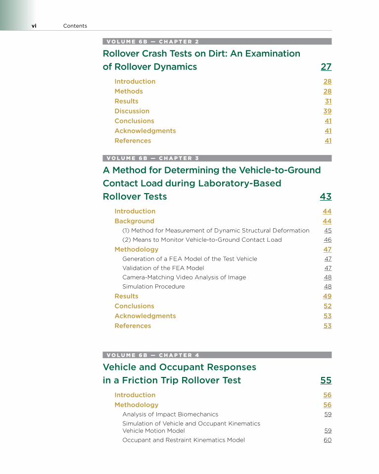
V O L U M E 6 B — C H A P T E R 2
Rollover Crash Tests on Dirt: An Examination of Rollover Dynamics 27
Introduction 28Methods 28Results 31Discussion 39Conclusions 41Acknowledgments 41References 41
V O L U M E 6 B — C H A P T E R 3
A Method for Determining the Vehicle-to-Ground Contact Load during Laboratory-Based Rollover Tests 43
Introduction 44Background 44
(1) Method for Measurement of Dynamic Structural Deformation 45
(2) Means to Monitor Vehicle-to-Ground Contact Load 46
Methodology 47Generation of a FEA Model of the Test Vehicle 47
Validation of the FEA Model 47
Camera-Matching Video Analysis of Image 48
Simulation Procedure 48
Results 49Conclusions 52Acknowledgments 53References 53
V O L U M E 6 B — C H A P T E R 4
Vehicle and Occupant Responses in a Friction Trip Rollover Test 55
Introduction 56Methodology 56
Analysis of Impact Biomechanics 59
Simulation of Vehicle and Occupant Kinematics Vehicle Motion Model 59
Occupant and Restraint Kinematics Model 60
Contents vii
Results 60Vehicle and Dummy Responses 60
Responses at Peak Neck Compression 68
Analysis of the Z-Axis Dynamics 73
Simulation of Vehicle and Occupant Kinematics Vehicle Motion Model 76
Discussion 79Effect of a Rigid Roof 79
Improving Occupant Safety in a Rollover 80
Dynamic Stiffness of the Hybrid III Neck 82
Injury Mechanism 82
References 83
V O L U M E 6 B — C H A P T E R 5
Rollover Testing on an Actual Highway 87Introduction 88
Loss of Control 88
Tripping 88
Rollover 88
Objective 89Methods 89
Rural Highway Testing 89
General Test Procedure 89
General Test Documentation 91
Closed Test-Track 92
Test Procedure 92
Test Documentation 93
Results 93Loss-of-Control Phase 94
Tripping Phase 95
Trip Velocity Extrapolation 96
Trip Velocity Integration 96
Rolling Phase 97
Discussion 101Conclusions 102Acknowledgments 104References and Biblography 104Appendix Test #1 1996 Buick Skylark No-Roll 106Appendix Test #2 1996 Buick Skylark 6 Rolls 109Appendix Test #3 1984 AMC Eagle 3 Rolls 112Appendix Test #4 1987 Ford Taurus No-Roll 115
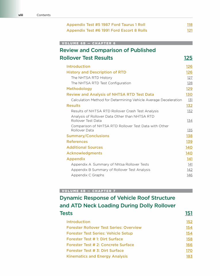
viii Contents
Appendix Test #5 1987 Ford Taurus 1 Roll 118Appendix Test #6 1991 Ford Escort 8 Rolls 121
V O L U M E 6 B — C H A P T E R 6
Review and Comparison of Published Rollover Test Results 125
Introduction 126History and Description of RTD 126
The NHTSA RTD History 127
The NHTSA RTD Test Configuration 128
Methodology 129Review and Analysis of NHTSA RTD Test Data 130
Calculation Method for Determining Vehicle Average Deceleration 131
Results 132Results of NHTSA RTD Rollover Crash Test Analysis 132
Analysis of Rollover Data Other than NHTSA RTD Rollover Test Data 134
Comparison of NHTSA RTD Rollover Test Data with Other Rollover Data 135
Summary/Conclusions 138References 139Additional Sources 140Acknowledgments 140Appendix 141
Appendix A Summary of Nhtsa Rollover Tests 141
Appendix B Summary of Rollover Test Analysis 142
Appendix C Graphs 146
V O L U M E 6 B — C H A P T E R 7
Dynamic Response of Vehicle Roof Structure and ATD Neck Loading During Dolly Rollover Tests 151
Introduction 152Forester Rollover Test Series: Overview 154Forester Test Series: Vehicle Setup 154Forester Test # 1: Dirt Surface 158Forester Test # 2: Concrete Surface 166Forester Test # 3: Dirt Surface 170Kinematics and Energy Analysis 183
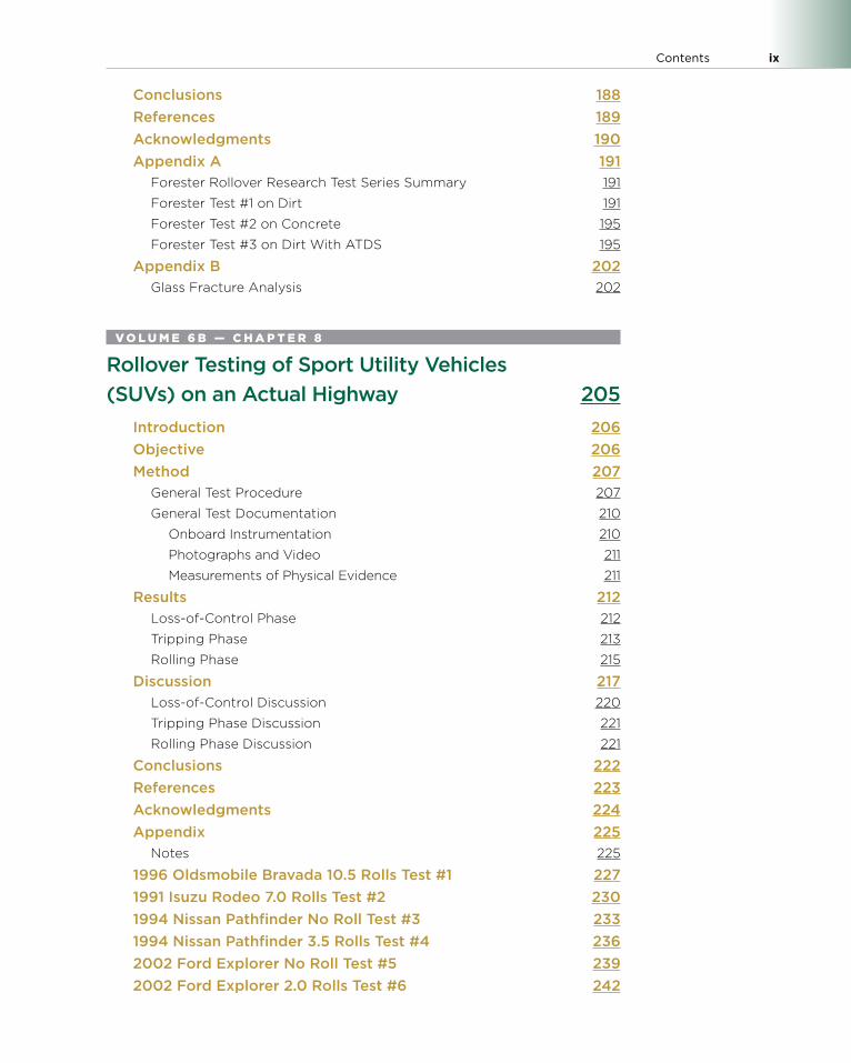
Contents ix
Conclusions 188References 189Acknowledgments 190Appendix A 191
Forester Rollover Research Test Series Summary 191
Forester Test #1 on Dirt 191
Forester Test #2 on Concrete 195
Forester Test #3 on Dirt With ATDS 195
Appendix B 202Glass Fracture Analysis 202
V O L U M E 6 B — C H A P T E R 8
Rollover Testing of Sport Utility Vehicles (SUVs) on an Actual Highway 205
Introduction 206Objective 206Method 207
General Test Procedure 207
General Test Documentation 210
Onboard Instrumentation 210
Photographs and Video 211
Measurements of Physical Evidence 211
Results 212Loss-of-Control Phase 212
Tripping Phase 213
Rolling Phase 215
Discussion 217Loss-of-Control Discussion 220
Tripping Phase Discussion 221
Rolling Phase Discussion 221
Conclusions 222References 223Acknowledgments 224Appendix 225
Notes 225
1996 Oldsmobile Bravada 10.5 Rolls Test #1 2271991 Isuzu Rodeo 7.0 Rolls Test #2 2301994 Nissan Pathfinder No Roll Test #3 2331994 Nissan Pathfinder 3.5 Rolls Test #4 2362002 Ford Explorer No Roll Test #5 2392002 Ford Explorer 2.0 Rolls Test #6 242
x Contents
1998 Ford Expedition 1.5 Rolls Test #7 2451991 Mitsubishi Montero 8.5 Rolls Test #8 248
V O L U M E 6 B — C H A P T E R 9
ATV Rollover Resistance: Testing of Side-By-Side ATV Rollover Initiations 251
Introduction 252Experimental Methods 252
Test Vehicle: Static Calculations 252
Test Vehicle: Measuring Moments of Inertia 253
Test Results: SSF and Inertias 254
Test Procedure: Dynamic Testing 255
Slowly Increasing Speed Maneuver 255
Testing Results 255
Discussion 257
Tire Properties of RUVs 257
Important Considerations Related to RUV Roll Initiation 257
Summary/Conclusions 257References 258Acknowledgments 259
V O L U M E 6 B — C H A P T E R 10
Evaluation of Dynamic Roof Deformation in Rollover Crash Tests 261
Introduction 262Test Series Description 263
Vehicle Instrumentation 265
High-Speed Digital Motion Cameras 265
Data Analysis 267Analysis of String Potentiometer Motion 267
Determining Dynamic Roof Deformation by Trilateration 267
Closed-Form Solution 271
Numerical Methods 271
Onboard 3D Photogrammetry 274
String Potentiometer vs. 3D Photogrammetry Data 275
Error Sources in Measurement 280
String Potentiometers 280
3D Photogrammetry 280
Post-Test Coordinate Measurements vs. End-of-Test Coordinate Locations 281
Measurement Technique Limitations 285
Contents xi
Conclusions 286References 287Acknowledgments 288Appendix 289
Test Data 289
V O L U M E 6 B — C H A P T E R 11
Comparing Dolly Rollover Testing to Steer-Induced Rollover Events for an Enhanced Understanding of Off-Road Rollover Dynamics 305
Introduction 306Methods 307Results 309
Peer Rollover Events 314
Group A 315
Group B 318
Discussion 319Conclusions 322References 323Appendix 325
V O L U M E 6 B — C H A P T E R 12
Rollover Crash Test Results: Steer-Induced Rollovers 333
Introduction 334Prior Publication of Steer-Induced Rollover Tests 334
Rollover Phases 334
Roll Phase 335
Rollover Drag Factor 335
GPS Speed Sensor 336
Methodology 336Test Setup 336
Vehicle Preparation 337
Crash Site Documentation 339
Test Vehicle Documentation 339
Rollover Reconstruction 339
Rollover Phase Duration 339
Over-The-Ground Speed Calculation 340
xii Contents
Verification of GPS Sensor Speed Output 341
Data Filtering 342
Results 342Rollover Tests 342
GPS Speed Output Verification Test 346
Trip Point 346
Discussion 348GPS Sensor Output Correction 348
Average Drag Factors 351
Bilinear Decelerations and Roll Rate Peak 351
Trip Point 352
Observations 352Conclusions 353Acknowledgments 353References 353Appendix A 355
Test Data 355
V O L U M E 6 B — C H A P T E R 13
Rollover Testing of Recreational Off-Highway Vehicles (ROVs) for Accident Reconstruction 371
Introduction 372Experimental Methods 372
Test Vehicle Preparation 372
Test Procedure 373
Results 374Scratch Mark Analysis 375
Summary/Conclusions 377References 378Acknowledgments 379Appendix 380
V O L U M E 6 B — C H A P T E R 14
Rollover Initiation Simulations for Designing Rollover Initiation Test System (RITS) 401
Introduction 402Method 403
Vehicle Modeling 403
Vehicle Validation 404
Contents xiii
Static Tests 404
Dynamic Rollover Tests 404
Effect of Initial Speed 404
Monte Carlo Analysis 405
RITS Overview 405
RITS Simulation Set-Up 406
Deceleration Pulse 406
Required Acceleration 407
Sensitivity Analysis 407
Results 407Model Validation 407
Effect of Initial Speed on Vehicle Kinematics 409
Monte Carlo Analysis 409
Touchdown Conditions vs. Required Acceleration 411
Change of the Speed of the Sled and Tripping Time 411
Touchdown Conditions vs. Deceleration Pulse 411
Discussion 413Vehicle Model 413
Effect of Initial Speed on Vehicle Kinematics 413
Monte Carlo Analysis 413
Ranges of Touchdown Parameters 413
Touchdown Parameters vs. Required Acceleration 413
Touchdown Parameters vs. Deceleration Pulse 414
Conclusions 414References 414Acknowledgments 416Appendix 416
Vehicle Testing 416
Model Validation 416
K&C validation 416
Dynamic Rollover Test Validation 418
V O L U M E 6 B — C H A P T E R 15
Rollover Testing of a Sport Utility Vehicle (SUV) with an Inertial Measurement Unit (IMU) 423
Introduction 424Method 425
General Test Procedure 425
General Test Documentation 428
Onboard Instrumentation 428
Video and Photographs 429
Measurements of Physical Evidence 429

xiv Contents
Results 430Pre-trip Phase 431
Tripping Phase 432
Rolling Phase 432
Data Correlation 433
Discussion of Results 434Positional Data 434
Velocity Data 435
Acceleration Data 438
Angular Velocity Data 440
Reconstruction Data 440
Conclusions 444Methodology 444
Documentation 444
Instrumentation 444
Rollover 445
References 445Acknowledgments 445Definitions/Abbreviations 446Appendix 447
About the Author 451
Collision Reconstruction Methodologies
Volume 6C: Rollover Accident Reconstruction
Warrendale, Pennsylvania, USA
©2019 SAE International v
contents
Introduction xxix
V O L U M E 6 C — C H A P T E R 1
Methodology for Simulation of Rollover Cases 1Introduction 1
Short History in Rollover Research 1
Short History in Rollover Tests 2
Short History in Rollover Protection 3
The Necessity for Rollover Methodology 3
Rollover Tool Chain Methodology 4Application and Results of the Rollover Tool Chain 5
Accident Scenario Module (ASM) 6
Active Safety Systems Design Module (ASSDM) 7
Restraint Systems and Interior Design Module (RSIDM) 9
Benefit and Injury Assessment Module (BIAM) 11
Conventional Assessment Parameters 11
Injury Assessment Parameters 12
Harm Assessment Parameters 13
Conclusion 14Acknowledgments 14References 14Definitions, Acronyms, Abbreviations 16
V O L U M E 6 C — C H A P T E R 2
Dolly Rollover Testing of Child Safety Seats 17Introduction 18Methodology 19Results 21
vi Contents
Discussion 22Conclusion 24References 24
V O L U M E 6 C — C H A P T E R 3
Trajectory Model of Occupants Ejected in Rollover Crashes 27
Introduction 28Methods 29
Generalized Vehicle Dynamics Model 29
Occupant Ejection Model 30
Model Parameter Optimization 32
Model Validation 33
Results 34Dolly Rollover Test 34
Model Parameter Optimization 34
Model Validation 36
Discussion 38Conclusions 40Acknowledgments 41References 41
V O L U M E 6 C — C H A P T E R 4
Modelling the Effects of Seat Belts on Occupant Kinematics and Injury Risk in the Rollover of a Sport Utility Vehicle (SUV) 43
Introduction 44Reconstruction and Validation of a Rollover Test 45
Rollover Test Descriptions 45
Reconstruction of the Rollover Test 45
Injury Evaluation 46
Validation of the Reconstruction 47
Results of Simulations 48Dummy Simulation with Seat Belts 48
Dummy Kinematics 48
Injury Analysis 48
Contents vii
Dummy Simulation Without Seat Belts 48
Dummy Kinematics 48
Injury Analysis 49
Human Body Simulation with Seat Belts 49
Human Body Kinematics 49
Injury Analysis 49
Human Body Simulation Without Seat Belts 50
Human Body Kinematics 50
Injury Analysis 50
Comparison 50
Discussion 52Human Body Model 52
Muscular Activation 52
Seat Belts 52
Roof Intrusion 53
Vehicle Movement 53
Injury Evaluation 53
Conclusions 53Acknowledgments 54References 55Appendix 58
V O L U M E 6 C — C H A P T E R 5
Soil-Trip Rollover Simulation and Occupant Kinematics in Real-World Accidents 65
Introduction 66Soil-Trip-Over 67
Rollover Accident Reconstruction with PC-Crash 67
Simplified Car Model for Soil-Trip-Over Simulation 69
Selection of Parameters of Simplified Soil-Trip Rollover Simulation 69
Results of Simplified Soil-Trip Rollover Simulation 70
Full Car Soil-Trip Rollover Simulation 70
Full Car Soil-Trip Rollover Simulation Results 71
Comparison of Kinematics in Dummy and Human Model 72Conclusions 76References 76Acknowledgments 77
viii Contents
V O L U M E 6 C — C H A P T E R 6
Occupant Ejection Trajectories in Rollover Crashes: Full-Scale Testing and Real-World Cases 79
Introduction 80Methods 80
Volvo XC90 Dolly Rollover Test 80
Real-World Rollover Crashes 81
Lincoln Navigator Rollover 81
GMC Yukon Denali Rollover 82
Model Parameter Optimization 82
Results 83Volvo XC90 Dolly Rollover Test 83
Real-World Cases 84
Lincoln Navigator Rollover 84
GMC Yukon Denali Rollover 85
Comparison to Dolly Rollover Tests 88
Ejection Marks 90
Discussion 90Conclusions 93Acknowledgments 93References 93
V O L U M E 6 C — C H A P T E R 7
Occupant Trajectory Model Using Case-Specific Accident Reconstruction Data for Vehicle Position, Roll, and Yaw 95
Introduction 96Methods 96
Vehicle Model 97
Reference Frames 97
Initial Conditions 98
Equations of Motion 99
Occupant Model 99
Occupant in Vehicle 100
Occupant in Air 101
Occupant on Ground 103
Contents ix
Results 103Discussion 108Conclusion 110References 111
V O L U M E 6 C — C H A P T E R 8
Vehicle and Occupant Responses in a Friction Trip Rollover Test 113
Introduction 114Methodology 114
Analysis of Impact Biomechanics 117
Simulation of Vehicle and Occupant Kinematics Vehicle Motion Model 117
Occupant and Restraint Kinematics Model 118
Results 118Vehicle and Dummy Responses 118
Responses at Peak Neck Compression 126
Analysis of the Z-Axis Dynamics 131
Simulation of Vehicle and Occupant Kinematics Vehicle Motion Model 134
Discussion 137Effect of a Rigid Roof 137
Improving Occupant Safety in a Rollover 138
Dynamic Stiffness of the Hybrid III Neck 140
Injury Mechanism 140
References 141
V O L U M E 6 C — C H A P T E R 9
Dynamic Response of Vehicle Roof Structure and ATD Neck Loading During Dolly Rollover Tests 145
Introduction 146Forester Rollover Test Series: Overview 148Forester Test Series: Vehicle Setup 148Forester Test # 1: Dirt Surface 152Forester Test # 2: Concrete Surface 160Forester Test # 3: Dirt Surface 164
x Contents
Kinematics and Energy Analysis 177Conclusions 182References 183Acknowledgments 184Appendix A 185
Forester Rollover Research Test Series Summary 185
Forester Test #1 on Dirt 185
Forester Test #2 on Concrete 189
Forester Test #3 on Dirt With ATDS 189
Appendix B 196Glass Fracture Analysis 196
V O L U M E 6 C — C H A P T E R 10
Validation of Occupant Trajectory Model Using the Ford Expedition Dolly Rollover Experimental Test Data 199
Introduction 200Methods 201
Reference Frames 201
Vehicle Evolution 202
Occupant at Ejection 202
Occupant at POR 205
Results 205Discussion 208Conclusion 212References 212Appendix 214
Appendix A 214
About the Author 217
Collision Reconstruction Methodologies
Volume 7A: Event Data Recorder Interpretation
Warrendale, Pennsylvania, USA
v©2019 SAE International
contents
Introduction xxv
V O L U M E 7 A — C H A P T E R 1
The Efficacy of Event Data Recorders in Pedestrian-Related Accidents 1
Introduction 1Methods 2
Test Vehicles 2
Pedestrian Dummy 2
Test Procedure 3
Data Acquisition and Post Processing 3
Results 3Discussion 6Conclusion 9Acknowledgments 9References 9
V O L U M E 7 A — C H A P T E R 2
Accuracy of Powertrain Control Module (PCM) Event Data Recorders 11
Introduction 11Methods 12
Results 14
Discussion 21VBOX Data Synch 21
Induced Errors 21
Conclusions 22Acknowledgments 22References 23Definitions, Acronyms, Abbreviations 23Appendix 1: Apparatus 24
vi Contents
V O L U M E 7 A — C H A P T E R 3
Accuracy of Selected 2008 Chrysler Airbag Control Module Event Data Recorders 27
Introduction 27Results 29
2008 Jeep Commander ACM EDR Vehicle Speed vs. Racelogic VBOX III at 100 Hz 29
2008 Commander Brake Switch Reporting Latency 32
2008 Dakota ACM EDR Vehicle Speed vs. Racelogic VBOX III 32
Dakota Brake Latency 36
Acceleretor Pedal Accuracy 36
Foot Movement Time from Accel to Brake 38
Discussion 38VBOX Data Synch 38
Data Truncation 39
Statistical Analysis 39
Conclusions 39Commander Speed Accuracy 39
Dakota Speed Accuracy 39
Brake Switch Latency 40
Accelerator Pedal Position Accuracy 40
Reporting Frequency 40
Acknowledgments 41References 41Definitions, Acronyms, Abbreviations 41Appendix: Apparatus 42
V O L U M E 7 A — C H A P T E R 4
Accuracy of Selected 2008 Ford Restraint Control Module Event Data Recorders 45
Introduction 45Sources of Vehicle Speed in EDRs 46
2008 Ford Focus and Edge Restraint Control Module 46
Results 472008 Ford Focus RCM vs. Racelogic VBOX II 47
2008 Edge RCM vs. Racelogic VBOX II 52
Focus/Edge Brake Switch Latency 56
Focus/Edge Accelerator Pedal Data Accuracy 57
Discussion 57VBOX Data Synch 57
Contents vii
EDR Speed Data Precision 58
EDR vs. Can Bus Speed Data Accuracy 58
Conclusions 592008 Ford Focus/Edge EDR Speed vs. VBOX 59
2008 Focus/Edge Brake Switch Latency 59
2008 Focus/Edge Accelerator Pedal Percent Accuracy 59
Acknowledgments 59
References 60Definitions, Acronyms, Abbreviations 60Appendix 61
V O L U M E 7 A — C H A P T E R 5
Accuracy of EDR During Rotation on Low-Friction Surfaces 65
Introduction 66Prior Art 66
Test Procedure 66
Results 68
Braking Mode Results 68
Heavy Throttle/Acceleration Test Runs 72
Light to No Accelerator Pedal Applied Results 74
Summary/Conclusions 76Braking Runs 76
Acceleration Runs 76
Light/No Throttle Runs 77
Overall 77
Future Research 77
References 78Acknowledgments 78Definitions/Abbreviations 78Appendix 79
V O L U M E 7 A — C H A P T E R 6
Chrysler Airbag Control Module (ACM) Data Reliability 99
Introduction 100Methodology 100
Test Runs 101
Results 103
Summary/Conclusions 119
viii Contents
References 120Acknowledgments 120Definitions/Abbreviations 120Appendix 121
V O L U M E 7 A — C H A P T E R 7
Accuracy of Event Data Recorder in 2010 Ford Flex During Steady-State and Braking Conditions 135
Introduction 136Purpose 136
Literature Review 136
Test Procedure 138Description of the Test Vehicle 138
Synchronizing Data Sources 139
Data Analysis and Results 140EDR to GPS Speed Differences 140
Steady Driving 141
Aggressive Braking 141
Regression Analysis Results 143
EDR to can Speed Differences 143
Data Truncation 143
Data Timing 143
GPS Speed Data and CAN Speed Data 144
Dependence on Acceleration 144
Accuracy and Timing of Other EDR Parameters 146
Accelerator Pedal Data 146
Timing of Brake Indicator 146
Applications and Example 146Speed without Braking 146
Speed during Braking 147
Method 1: Data Driven Bounds 147
Method 2: Kinematic Relationship 147
Summary and Conclusions 148 Speed Data without Braking 148
Speed Data during Braking 148
Remarks 149
References 149Acknowledgments 150Definitions/Abbreviations 151Appendix 152
Contents ix
V O L U M E 7 A — C H A P T E R 8
Evaluation of Camry HS-CAN Pre-crash Data 163Introduction 163HS-CAN Messages 164Vehicle Speed 164HS-CAN Speed Evaluation 165Speed Correlation Tests 166Speed Analysis 166Discussion 170Engine Speed 170Analysis 171Discussion 173Accelerator Pedal Position 173
HS-CAN Measurement of APPS #1 173
Analysis 174
Discussion 176
Brake 176Discussion 178
Event Data Recorder 178Analysis 178
Engine rpm 178
Vehicle Speed 180
Brake Status and APPS #1 180
Conclusions 180Vehicle Speed 180
Engine Speed 180
Accelerator Pedal Position Sensor 180
Brake Application 181
EDR Correlation 181
References 181Acknowledgments 181Definitions/Abbreviations 182Appendix 182
Test Vehicle and Instrumentation 182
V O L U M E 7 A — C H A P T E R 9
Confirmation of Toyota EDR Pre-crash Data 185
Introduction 186EDR Location 187
x Contents
Recording EDR Events 187Data Tolerances 187Test Methods and Results 188
Setup and Test Matrix 188
Test Results and Analysis 189
Summary/Conclusions 190References 191Definitions/Abbreviations 191Appendix 192
Appendix A: Tolerance Factors 192
Appendix B: Test Conditions 192
Appendix C: Test Conditions 193
Appendix D: Camry Plots 194
Appendix E: 4Runner Plots 196
Appendix F: Prius Plots 198
V O L U M E 7 A — C H A P T E R 1 0
Accuracy of Event Data in the 2010 and 2011 Toyota Camry During Steady-State and Braking Conditions 201
Introduction 202Literature Review 202Theory of Operation 204Data Collection Procedure 205Data Analysis and Discussion 206
Can Bus Data 206
Steady-State Vehicle Speed 208
Speed During Heavy Braking 209
Factors Affecting Speed Difference 212
Speed Message Timing 213
Timing from Trigger to First Data Point 214
Other ACM-Recorded Precrash Values 217
Summary/Conclusions 218Limitations 219References 220Acknowledgments 221Definitions/Abbreviations 221Appendix 222
Contents xi
V O L U M E 7 A — C H A P T E R 1 1
Assessing the Accuracy of Vehicle Event Data Based on CAN Messages 225
Introduction 226Related Previous Work 226
Networking Principles 226
Accuracy Analysis: Can Data Only 228Experiment Description 228
Data Recording: Preparation and Implementation 228
Data Analysis 228
Experimental Results 230
Accuracy Analysis: Can and EDR Data 232Experiment Description 232
Data Recording: Preparation and Implementation 233
Experimental Results 234
Speed Accuracy 235
Message Timing 235
Arduino Hardware Platform 237Hardware 237
Software 238
Arduino Future Development 239
Summary and Conclusions 239References 240Acknowledgments 241Appendix 242
Appendix A: Powerspec—Sudden Deceleration Data Report 242
V O L U M E 7 A — C H A P T E R 1 2
Accuracy of Pre-crash Speed Recorded in 2009 Mitsubishi Lancer Event Data Recorders 245
Introduction 246Test Vehicle 248Data Collection Procedure 250
Test Series #1 251
Test Series #2 251
Synchronizing Data Sources 251
Results 252Test Series #1 252
Test Series #2 253

xii Contents
Discussion 255Conclusions 257References 258Acknowledgments 259Appendix A 259
About the Author 261

Collision Reconstruction Methodologies
Volume 7B: Event Data Recorder Interpretation
Warrendale, Pennsylvania, USA
v©2019 SAE International
contents
Introduction xxv
V O L U M E 7 B — C H A P T E R 1
Accuracy and Characteristics of 2012 Honda Event Data Recorders from Real-Time Replay of Controller Area Network (CAN) Traffic 1
Introduction 3Literature Review 3Methodology 6
Data Collection 6
Nondeployment Event Generation 9
CAN Replay Experiments 11
Results and Discussion 12CAN Identifier Maps 12
CAN Speed Accuracy Tests 15
2012 CR-V Normal Driving 15
Civic Steady State 16
CDR Reported Precrash and Crash Data 17
2012 CR-V Accuracy during Maximum ABS Braking 17
2012 Civic EDR Accuracy during Maximum ABS Braking 20
Timing between 0 and −0.5 Data Points in the Precrash Data 22
Dynamic Steering Maneuvers 23
Conclusions 25Data Accuracy Testing Methodology 25
2012 CR-V Speed Data 25
2012 Civic Speed Data 25
Other SRS Reported Data 26
Acknowledgments 26Nomenclature 26References 26
vi Contents
Appendix 28Appendix A: Honda Can Bus IDS 28
Appendix B: Can Replay System Design 29
Data Transformation and Storage 29
Design Considerations for CAN Transmission 29Windows PC 30
Real-Time Operation System 30
Field Programmable Gate Array 30
Replay Timing Feedback 30
Software Implementation 31
Appendix C: Time Adjustment for Civic Data 34
V O L U M E 7 B — C H A P T E R 2
Validation of Event Data Recorders in High Severity Full-Frontal Crash Tests 37
Introduction 38Delta-V Accuracy 38
Speed Data Accuracy 39
Seatbelt Buckle Accuracy 39
Objective 39Approach 39
Development of the EDR Dataset 40
Crash Test Instrumentation Selection 40
Event Recording Complete Status 40
Seatbelt Buckle Status 41
Airbag Deployment 41
Precrash Vehicle Speed 41
Delta-V 41
Time Zero Alignment 41
Delta-V Alignment 44
Results 44Seatbelt Buckle Status 44
Airbag Deployment 45
Pre-crash Vehicle Speed 45
Delta-V 46
Discussion 49Conclusions 50References 51Definitions/Abbreviations 52Appendix 53
Contents vii
V O L U M E 7 B — C H A P T E R 3
The Accuracy and Sensitivity of 2005 to 2008 Toyota Corolla Event Data Recorders in Low-Speed Collisions 69
Introduction 70Methods 70
Instrumentation 71
Test Procedure 71
Vehicle Tests 71
Sled Tests 72
Data Reduction 72
Results 74Vehicle Tests 74
Frontal Impacts 74
Rear-End Impacts 75
Sled Tests 76
Vehicle Crash Pulse Replications 76
Haversine Crash Pulses 76
ACM Model 78
Repeatability 80
Trigger Event Overwriting Logic 80
Discussion 80Conclusions 82References 83Acknowledgments 83Appendix 84
V O L U M E 7 B — C H A P T E R 4
Accuracy of Translations Obtained by 2013 GIT Tool on 2010-2012 Kia and Hyundai EDR Speed and Delta V Data in NCAP Tests 87
Introduction 87Literature Search 88
Kia and Hyundai Tool 89
Methods 90Results 92
Precrash Speed Data Time Series (Element 2-1) 92
Longitudinal Delta V Time Series (Element 1-1) 93
viii Contents
Maximum Longitudinal Delta V (Element 1-2) 93
Time to Maximum Delta V (Element 1-3) 94
Lateral Delta V Time Series (Element 1-4) 94
MDB Tests 94
Pole Tests 95
Maximum Lateral Delta V (Element 1-5) 96
Time to Max Lateral Delta V (Element 1-6) 97
Time to Max Total Delta V (Element 1-7) 97
Discussion 97Conclusions 97References 98Acknowledgments 99Definitions/Abbreviations 99Appendix 100
Appendix 1 - Frontal Crash Test Longitudinal Delta V in EDR versus Reference 100
Appendix 2 - Frontal Crash Test Speed Prior to Impact in EDR versus Reference 103
Appendix 3 - EDR Memory Section 1 Elements “Stoplight Chart” by Test Type (Green Indicates Plausible, Yellow not Expected, Red Implausible for the Test) 104
Appendix 4 - EDR Memory Section 2 Data Elements 1-16 by Test Type 105
Appendix 5 - EDR Section 2 Elements 17-34 Stoplight Chart 106
Appendix 6 - EDR Section 3 Data Elements And Current Data Stoplight Chart by Test Type 107
Appendix 7 108
Appendix 8 - Chart of Kia/Hyundai Models that were Tested in this Study versus Models Officially Supported by the EDR Tool 112
Appendix 9 - Discussion of Other Data Elements 113
Rollover (Element 1-8) 113
Throttle Time Series (Element 2-2) 113
Brake Time Series (Element 2-3) 113
Ignition Cycles at Event (Element 2-4) 113
Driver Belt Status (Element 2-5) 113
Airbag Warning Light On (Element 2-6) 113
Time to Deploy Frontal Driver Stage 1 (Element 2-7) 113
Time to Deploy Frontal Passenger Stage 1 (Element 2-8) 114
Event Number (Element 2-9) 114
Time Between Events (Element 2-10) 114
Event Recording Complete (Element 2-11) 114
RPM Time Series (Element 2-12) 114
ABS On/Off Time Series (Element 2-13) 114
Stability Control On/Off Time Series (Element 2-14) 114
Contents ix
Steering (Element 2-15) 115
Passenger Belt Status (Element 2-16) 115
Driver Seat Position Forward (Element 2-17) 115
Passenger Seat Position Forward (Element 2-18) 115
Driver Occupant Classification System (Element 2-19) 115
Passenger Occupant Classification System (Element 2-20) 115
Time to Deploy Driver Frontal Airbag St. 2 (Element 2-21) 115
Time to Deploy Pass Frontal Airbag St. 2 (Element 2-22) 116
Time to Deploy Driver Side Airbag (Element 2-23) 116
Time to Deploy Passenger Side Airbag (Element 2-24) 116
Time to Deploy Driver Side Curtain (Element 2-25) 116
Time to Deploy Passenger Side Curtain (Element 2-26) 116
Time to Deploy Driver Pretensioner (Element 2-27) 116
Time to Deploy Passenger Pretensioner (Element 2-28) 116
Driver 2nd Stage Airbag Disposal (Element 2-29) 116
Driver 3rd Stage Airbag Disposal (Element 2-30) 117
Passenger 2nd Stage Airbag Disposal (Element 2-31) 117
Passenger 3rd Stage Airbag Disposal (Element 2-32) 117
Time to Deploy Driver Stage 3 (Element 2-33) 117
Time to Deploy Passenger Stage 3 (Element 2-34) 117
Longitudinal Acceleration Time Series (Element 3-1) 117
Lateral Acceleration Time Series (Element 3-2) 117
Vertical Acceleration Time Series (Element 3-3) 117
Ignition Cycles at Download (Real Time Element) 117
Second Events 118
Hex Data 118
V O L U M E 7 B — C H A P T E R 5
Validation of Event Data Recorders in Side-Impact Crash Tests 119
Introduction 120Objective 120Approach 120
Development of the EDR Dataset 121
Event Recording Complete Status 121
Crash Test Instrumentation Selection 121
Delta-V 122
Rotation Correction 123
Time Zero Alignment 124
Seatbelt Buckle Status 126
Airbag Deployment 126
x Contents
Results 127Delta-V 127
Seatbelt Buckle Status 128
Airbag Deployment 129
Discussion 130Conclusions 131References 132Acknowledgements 133Abbreviations 133Appendix 134
V O L U M E 7 B — C H A P T E R 6
Accuracy and Timing of 2013 Ford Flex Event Data Recorders 161
Introduction 162Motivation 162
Objective 162
Literature Review 162
Overview and Organization 163
Procedure 163Driving Data Acquisition 163
CAN ID Reverse Engineering 164
Acceleration Sled Testing 164
Results 166Steady State Speed Testing 166
Speed Data During Hard Braking 169
Pre-crash Stability Control Data: Longitudinal Acceleration 172
Pre-crash Stability Control Data: Yaw Rate 173
Pre-crash Stability Control Data: Lateral Acceleration 175
Pre-crash Stability Control Data: Steering 175
Delta V Data 177
Accuracy Analysis 178Steady State Speed Data Testing 178
Hard Braking Speed Data Testing 178
Stability Control Data Testing 179
Summary and Conclusions 179References 180Acknowledgments 181Definitions/Abbreviations 182Appendix 183
Contents xi
V O L U M E 7 B — C H A P T E R 7
Analysis of Crash Data from a 2012 Kia Soul Event Data Recorder 187
Introduction 188Literature Review 191Test Vehicles 192Data Collection Procedure 193
Methodology 193
Test Series 1 193
Test Series 2 194
Results 197Test Series #1 197
Test Series #2 199
Discussion 203Conclusions 206References 207Acknowledgments 208Glossary 208
V O L U M E 7 B — C H A P T E R 8
EDR Pulse Component Vector Analysis 211Introduction 212Equipment 213
HYGE™ Acceleration-Type Sled System 213
Bosch CDR 214
Subject EDRs 214
Apparatus 215
Procedure 217
Initialization/Validation 217
Testing 217
Results 219
Yaw Test Results 220
Resultant Delta-V 220
Apparent Yaw Angle 221
RAM 1500 Delta-V Data Detail 221
Pitch Test Results 222
Discussion 223
Summary/Conclusions 223Further Research Opportunities 224References 224
xii Contents
Definitions/Abbreviations 225Appendix 226
Appendix A 226
Appendix B 227
Appendix C 228
V O L U M E 7 B — C H A P T E R 9
Comparison of the Accuracy and Sensitivity of Generation 1, 2, and 3 Toyota Event Data Recorders in Low-Speed Collisions 229
Introduction 230Methods 231
ACMs 231
Instrumentation 231
Test Procedure 232
Data Reduction and Analysis 232
Results 233Repeatability 233
Trigger Threshold 234
Accuracy 235
Discussion 237Conclusions 240References 241Acknowledgments 242Appendix 243
Appendix A - Repeatability Data 243
Appendix B - Trigger Threshold Data 245
Appendix C - Full Model Regression Results 247
Appendix D - Residuals 249
V O L U M E 7 B — C H A P T E R 1 0
Event Data Recorder (EDR) Developed by Toyota Motor Corporation 251
Introduction 252 EDRs Developed by Toyota 253
Prior to EDR Regulations 253
Compliance with EDR Regulations 254
Addition of Pre-crash Data 255
Contents xiii
Post-crash Data Required for Crash Reconstruction 256Frontal Crash 256
Additional Side Crash Data Recording 258
Rollover Record 258
Recording of PUH Pedestrian Protection System 262
Recording by Non-crash Trigger 264
Download Tool 265
Automatic Collection of EDR Data 266 Trial of Advanced Automatic Collision Notification System 270Conclusion 274References 274Appendix 275
Appendix A - EDR Adoption Status in North America 275
Appendix B - Downloaded PUH System EDR Data 276
Appendix C - Trigger Items of VCH 276
Appendix D - VCH Data Example (2014 IS) 277
Appendix E - VCH Data Example (2014 IS) 277
Appendix F - Collected EDR Data Example 278
V O L U M E 7 B — C H A P T E R 1 1
Longitudinal Delta V Offset Between Front and Rear Crashes in 2007 Toyota Yaris Generation 04 EDR 279
Introduction 280Testing Scope and Methodology 280Results 281Analysis 284Discussion 287Summary/Conclusions 289References 289Acknowledgments 290Definitions/Abbreviations 290Appendix 291
Appendix A 291
Appendix B 292
Appendix C 293
Appendix D 294
xiv Contents
V O L U M E 7 B — C H A P T E R 1 2
A Compendium of Passenger Vehicle Event Data Recorder Literature and Analysis of Validation Studies 299
Introduction 300Body of Literature 301Data Selection 302Analysis: Precrash Data (Vehicle Speed) 303
Other Precrash Studies Not Analyzed 308
Analysis: Crash Data (Vehicle Velocity Change, ΔV ) 308Kia and Hyundai Vehicles Using the GIT Tool 309
Studies: Evaluation of Event Data Recorders in Full Systems Crash Tests (Niehoff, 2005) and Preliminary Evaluation of Advanced Air Bag Field Performance Using Event Data Recorders (Gabler, 2008) 310
Direct Contact Damage to the Module and Acceleration Clipping 311
Small or Partial Overlap Testing 311
Side Impact Testing 313
Side Pole Impact Testing 313
Impact and Velocity Change (ΔV ) Testing 315Automobile versus Pedestrian Testing 315
Automobile versus Motorcycle Testing 315
Low-Speed Vehicle-to-Vehicle and Vehicle-to-Barrier Testing 316
Vehicle to Heavy Truck Rear Underride Guard Testing 316
Crash Simulation Sled System Testing 316
Studies of Event Data Recorders on Vehicles in Japanese NCAP Crash Tests 317
Discussion 317Summary 318References 318Acknowledgments 321Appendix 322
Appendix A - Bibliography (All Studies) 322
Appendix B - Instrumented Testing Bibliography 334
Appendix C - Papers By Make, Year, and Model 340
Appendix D - Instrumented Testing Data Plots 345
Appendix E - Instrumented Testing Raw Data 354
Contents xv
V O L U M E 7 B — C H A P T E R 1 3
An Analysis of EDR Data in Kawasaki Ninja 300 (EX300) Motorcycles 377
Introduction 378Testing Details 379Data Triggering 380Pre-emergency Shut-Down Data 385Power Loss Issues 387Summary/Conclusions 389References 390Definitions/Abbreviations 390Appendix 391
Appendix A: Sample EDR Event Data Table 391
Appendix B: EDR Flow Chart 394
About the Author 395
Collision Reconstruction Methodologies
Volume 8: Error Analysis and Uncertainty in Accident
Reconstruction
Warrendale, Pennsylvania, USA
v©2019 SAE International
Introduction xi
C H A P T E R 1
Evaluating Uncertainty in Accident Reconstruction with Finite Differences 1
Introduction 2Mathematical Basis 2Data Sources 3Implementation 3Example 1: Simple Case 4Example 2: Finite Differences with A/R Software 8Example 3: Intersection Impact 9Conclusions 12Acknowledgments 12References 13Appendix A 14
Distance by Total Station 14
Distance 15
Arc 15
Angle 15
Right Angle 15
Weight 15
Mass Dispersion 15
Wheelbase 16
Tire-Road Friction, in situ 16
Tire-Road Friction, generic 16
Lateral Friction, generic 17
Post-Impact Unbraked Drag 17
Crush Depth 17
Crush Width 17
Crush Location 17
Crush Direction 17
Tiremark Measurement 18
contents
vi Contentsvi Contents
C H A P T E R 2
The Practical Application of Finite Difference Analysis in Accident Reconstruction 19
Introduction 20Exemplar Reconstruction 20
Forensic Task 20Reconstruction 20
Site and Vehicle Data 24Damage Data 24Output Data 24Site Plot 24Vector Plot 24
Results of Exemplar Reconstruction 25Finite Difference Analysis 25
Procedure 25Exemplar Deviations 25Deviation Summations 26Approach Speed Deviations 27
Component Deviations 28
Care In Measurement 29Transferability 29
Approach Analysis 29Approach analysis without FDA 30
Likely Approach Scenario without FDA 30Alternative Approach Scenario Without FDA 31
Approach Analysis With FDA 31Likely Approach Scenario with FDA 31Alternative Approach Scenario With FDA 32
Conclusions 34Acknowledgments 35References 35Appendix A: Accident Reconstruction Routines and Finite Difference Analysis 36Appendix B: Probable Uncertainties of Measurement 38
C H A P T E R 3
The Accuracy of Photogrammetry vs. Hands-On Measurement Techniques Used in Accident Reconstruction 39
Introduction 40Method 41
Hands-On Measurement 42Photogrammetry Measurement 43Baseline Total Station Measurements 43
Contents vii Contents vii
Results 45Discussion 50Summary/Conclusions 52References 52Acknowledgments 54Appendix A 55
C H A P T E R 4
Considerations for Applying and Interpreting Monte Carlo Simulation Analyses in Accident Reconstruction 57
Introduction 58Calculations used for Comparison 58Selecting Input Distributions 59Determining the “Most Likely” Range for a Nonnormal Distribution 61Conclusion 63Acknowledgments 64References 64
C H A P T E R 5
Photogrammetric Measurement Error Associated with Lens Distortion 67
Introduction 68Background 68Testing Procedure 70Creating an Undistorted Image 70Manually Assessing Lens Distortion Coefficients in a Camera 72Sample Procedure 73Results of the Study 76Effect of Lens Distortion in Real-World Measurements 79Conclusions 81References 82Appendix A (Distortion Distance, per Camera, per Focal Length) 83Appendix B (Correction Coefficient Database) 118
viii Contentsviii Contents
C H A P T E R 6
Sensitivity of Monte Carlo Modeling in Crash Reconstruction 123
Introduction 124Probability Concepts 125
Distributions 125Mathematical Expectation 126
Probability of Excess 127
The Score Function Method 128Sensitivity of the Mean 128
Sensitivity of the Standard Deviation 129
Sensitivity of the Probability of Excess 130
Determining Kernel Functions 130
Univariate Normal Distribution 131
Bivariate Normal Distribution 131
Example of Energy from Residual Crush 132Problem Summary and Results 132
Convergence Study 133
Sensitivity of Results 135
Interpretation of Results 137
Conclusion 138References 138Acknowledgments 140
C H A P T E R 7
Monte Carlo Techniques for Correlated Variables in Crash Reconstruction 141
Introduction 142Probability Concepts 142
Multivariate Probability 142
Joint Correlated Distributions 142
Conditional and Marginal Distributions 144
Functions of Random Variables 146
Linear Combinations 147
Taylor Series Approximation 148
Test for Statistical Independence 148
The Monte Carlo Method 148
Modeling and Simulating Correlated Normal Variables 149Theory 149
Example of Determining Energy From Crush 150

Contents ix
Predicting Correlation 153Interpreting Correlated Results from a Monte Carlo Simulation 155Conclusions 158Acknowledgments 159References 159
About the Author 161
Contents ix
Collision Reconstruction Methodologies
Volume 9: Bicycle Accident Reconstruction
Warrendale, Pennsylvania, USA
v©2019 SAE International
contents
Introduction xi
C H A P T E R 1
Use of Throw Distances of Pedestrians and Bicyclists as Part of a Scientific Accident Reconstruction Method 1
Introduction 2Basis of Speed Calculation 2New Results Based on Real Accidents 4
Kinematics of Impact 5
Relation between Throw Distances and Impact Speed 5Injury Relation to Impact Speed and Throw Distance 9Conclusion 11References 13
C H A P T E R 2
A Study of a Method for Predicting the Risk of Crossing-Collisions at Intersections 15
1. Introduction 162. Analysis of Traffic Accident Data 17
Breakdown of Crossing-Collisions 17
Combinations of Intersection Types and Accident Parties 18
Pre-crash Driving Patterns of Primary and Secondary Parties 19
3. Quantification of Crossing-Collision Risk 20Method of Estimating Crossing-Collision Risk 20
Method of Estimating P(A) for Individual Accident Factors 20
4. Estimation of Crossing-Collision Probabilities for Different Types of Intersections 21Estimation Method 21
Data Used and Estimated Results 22
5. Estimation Of Crossing-Collision Probabilities by Driving Pattern of Non-Right-Of-Way Vehicles 23Estimation Method 23
Data Used and Estimated Results 23
6. Estimation of Crossing-Collision Probabilities by Type of Other Vehicle 24Estimation Method 24
Data Used and Estimated Results 24
7. Estimation of Accident Reduction Effect of Various Safety Measures 25Estimation of the Effect of Infrastructure Implementation on Reducing Accidents 25
Estimation of the Effect of a Driver-Support System on Reducing Accidents 25
Comparison of Accident Reduction Effect of Infrastructure Implementation and Driver-Support System 27
8. Conclusions 27References 28
C H A P T E R 3
Road Bicycle Dynamics in the Presence of Idealized Roadway Irregularities 29
Introduction 29Literature Review 30Steady-State Cornering 30Modeling of Contacts with Irregularities 31Derivation of Pitchover Conditions 32Dynamics of Ramp Climbing 34Test Program 35
Bicycle Dynamics Over Idealized Roadway Irregularities 35
Conclusions 36References 36Nomenclature 38
C H A P T E R 4
Analysis of Bicycle Pitch-Over in a Controlled Environment 39
Introduction 40Defining Pitch-Over 40
Dynamics 41
Center of Gravity (CG) Location 41
Minimum Deceleration Required for Pitch-Over 41
vi Contents
vii Contents vii
Minimum Velocity 41
Instant Center of Rotation at Pitch-Over Initiation 42
Front Wheel Lift Off 42
Testing 42Setup 42
Bicyclist 43
Landing Zone 43
Load Plates 43
Sync Flash 44
Data Acquisition 44
Dowel Shooter 44
Video and Still Camera Documentation 44
Test Articles 45
Procedures 45
Error 46
Test Series 47
Brake Application 47
Dowel Insertion 47
Barrier Impact 47
Data Processing and Motion Analysis 47
Results 48Bicycle Damage 48
Brake Application Test Series 48
Dowel Insertion Test Series 50
Barrier Impact Test Series 53
Discussion 56Conclusion 57Acknowledgments 58References 58Appendix A - Bicycle Configuration 59
C H A P T E R 5
Influences on the Risk of Injury of Bicyclists’ Heads and Benefits of Bicycle Helmets in Terms of Injury Avoidance and Reduction of Injury Severity 61
Introduction 61Framework of Evaluation 65Documentation Method of GIDAS 66Descriptive Outcome Processing 66Accident and Injury Patterns of Bicyclists 66
Injury Severities of the Heads of Bicyclists Involved in an Accident 69Usage of Bicycle Helmets by Different Types of Bicyclists and In Relation to Different Accident Characteristics 70Effectiveness of the Bicycle Helmets 72Statistical Evaluation of the Influence of Different Parameters on Head Injuries 74Damage Pattern on the Helmet 75Conclusion 78References 79Acknowledgments 81
C H A P T E R 6
Wrap Around Distance (WAD) of Pedestrians and Bicyclists and Relevance as an Influence Parameter for Head Injuries 83
Introduction and Objectives 84Measurement of the WAD in Real Accidents 87Study Tasks 88Accident Studies Based on GIDAS 88Database 89Evaluation Structure of the Study 89A. Descriptive Analysis 90
A.1. Injury Severity Grade of the Head (AIS Head) 90
A.2. Direction of VRU Related to Driving Direction of the Car 92
A.3. Collision Speed of the Car 93
A.4. Head Impact Point—Lateral Distance to Longitudinal Car Axis 93
A.5. Head Impact Point—WAD 94
A.6. Influence of the Age of the VRU to the Injury Severity of the Head 94
B. Multivariate Analysis 95B.1. Statistical Analysis of Influence Importance of WAD,
Impact Speed of the Car, and Body Height and Age of the VRU for Head Injury Occurrence 96
Conclusion and Discussion 101References 102Acknowledgments 103
viii Contents
ix
C H A P T E R 7
Cycling Characteristics of Bicycles at an Intersection 105
Introduction 106Experiment Method 108
Site of the Investigation 108
Subjects of the Investigation 110
Investigation Items 110
The Extent to Which Traffic Regulations Were Observed 110
Cycling Characteristics of the Cyclists 110
The Velocity of the Cyclists 110
Trajectory 110
The Timing the Cyclists Stopped Pedaling 111
Method of Analysis 111
Results of the Experiment 111Percentage of Cyclists Who Confirmed Safety at the Intersection 111
The Percentage of Cyclists Coming to a Stop at the Intersection 112
Velocity of the Cyclists 113
Changes in the Bicycles’ Velocity when Entering into the Intersection 113
Trajectory of the Cyclists 115
Investigation of TTI 115
Timing of the Warning Given to Cyclists to Prevent a Collision 117
Conclusion and Discussion 1181. Confirming It Is Safe to Cross and Coming to a Stop at the
Intersection 118
2. Cyclist’ Velocity 119
3. Changes in Cyclists’ Speed when They Entered the Intersection 119
4. Bicycles’ Trajectory 119
5. Timing of the Warning to Prevent Collisions 119
References 120Acknowledgments 120
About the Author 121
Contents ix
Collision Reconstruction Methodologies
Volume 10A: Pedestrian Collisions
Warrendale, Pennsylvania, USA
v©2019 SAE International
contents
Introduction xvii
V O L U M E 1 0 A — C H A P T E R 1
Investigation and Analysis of Real-Life Pedestrian Collisions 1
Introduction 2Methods 5
Background 5
Video Capture 5
Calibration 5
Data Analysis 6
Results 6Wrap Trajectories 6
Forward Projection Trajectories 8
Fender Vault Trajectories 9
Discussion 10Conclusion 11References 11
V O L U M E 1 0 A — C H A P T E R 2
Different Factors Influencing Post-Crash Pedestrian Kinematics 13
Introduction 14NASS-PCDS Analysis 15Principal Component Analysis 18Characteristics of Vehicle-Pedestrian Interaction 20Fe Analysis of Human Model 22
Adult Male 23
6-Year-Old Child 24
Ground-To-Head-Contact Distance 27Head Injury 29Standing Posture 31
Conclusions 32References 34Acknowledgments 36
V O L U M E 1 0 A — C H A P T E R 3
Pedestrian Behavior at Signal-Controlled Crosswalks 37
Introduction 38Experimental Methodology 40
Experimental Setup 40
Data Acquisition 40
Results 42Perception/Reaction 42
Pedestrian Speeds 42
Conclusion 43Acknowledgments 44References 44
V O L U M E 1 0 A — C H A P T E R 4
Throw Model for Frontal Pedestrian Collisions 45Introduction 46Pedestrian Impact Model 48
Throw Distance Model 48
Modeling of xL 50
Vehicle Motion 50
Throw Distance Index 50
Reconstruction Throw Model 51
Experimental Data 52Pedestrian Drag Factors 52
Experimental Values of Hill 52
Correction for Impact 52
Dummy Clothing Dependence 53
Experimental Throw Data 53
Preliminary Analysis of Experimental Data 53
Comparison of Model With Data 54
Reconstructed Wrap Collisions 55
Adult Dummy Wrap Collisions 57
Forward Projection Collisions 58
vi Contents
Contents vii
Roof Vault and Somersault Collisions 59
Fitting of the Reconstruction Model 59
Discussion and Conclusions 60Acknowledgment 61References 61
V O L U M E 1 0 A — C H A P T E R 5
Pedestrian Throw Kinematics in Forward Projection Collisions 65
Introduction 66Methodology 67
Pedestrian Dummy 67
Test Vehicles 67
Data Acquisition and Post Processing 68
Test Procedure 68
Results 69Forward Projection Trajectory: Dry Surface 69
Forward Projection Trajectory: Wet Surface 69
Forward Projection Throw Distance 70
Discussion 75Conclusion 76Acknowledgments 77References 77
V O L U M E 1 0 A — C H A P T E R 6
Use of Throw Distances of Pedestrians and Bicyclists as Part of a Scientific Accident Reconstruction Method 79
Introduction 80Basis of Speed Calculation 80New Results Based on Real Accidents 82
Kinematics of Impact 83
Relation between Throw Distances and Impact Speed 83Injury Relation to Impact Speed and Throw Distance 87Conclusion 89References 91
viii Contents
V O L U M E 1 0 A — C H A P T E R 7
Influence of Vehicle Body Type on Pedestrian Injury Distribution 93
Introduction 94Methods 95
Data Source 95
Inclusion and Exclusion 95
Injury Risk by Body Region and Vehicle Source 95
Results 95Injury by Body Region 95
Injury by Vehicle Component 96
LTVs 96
Cars 97
Discussion 98Injury Distribution by Body Region 98
Injury Distribution by Vehicle Source 98
Conclusion 99References 99Definitions, Acronyms, Abbreviations 100
V O L U M E 1 0 A — C H A P T E R 8
Vehicle Lighting to Enhance Pedestrian Visibility 101
Introduction 101Pedestrian Vulnerability 102Detection Distance Requirements 102
Avoidance—Timing 102
Perception/Reaction Time Delay 102
The Temporal Bonus 103Time Needed to Walk Clear of Vehicle Path 104
Estimating the Temporal Bonus 104Driver-Reaction-Distance 106
Detection Distance Necessary to Avoid 106
Where is The Pedestrian? 106Pedestrian Lateral Location 106
Pedestrian Vertical Location 107
How Much Illumination? 107Discussion - Part I - The Good News 108Discussion - Part II - Some Alternatives 109
Contents ix
Conclusion 109Acknowledgments 110References 110Appendix A Pedestrian Location with Respect to Headlamps 111
V O L U M E 1 0 A — C H A P T E R 9
Uncertainty Analysis of the Preimpact Phase of a Pedestrian Collision 113
Introduction 114Sensitivity to Uncertainty 114Maximum Uncertainty and Mean Square Uncertainty 116Monte Carlo Simulation 117Example and Discussion 117
Accident Scenario 117
Data 117
Accident Reconstruction. Time-Distance Analysis 118
Graphical Method 118Criterion of Driver’s Reaction Time Delay Evaluation 119
Analytical Method and Uncertainty Ranges 120Criterion of Driver’s Reaction Time Delay Evaluation 123
Monte Carlo Simulation 123Criterion of Driver’s Reaction Time Delay Evaluation 126
Comparison of Results 126
Conclusion 127References 128
V O L U M E 1 0 A — C H A P T E R 10
Pedestrian Dummy Pelvis Impact Responses 129Introduction 130Materials and Method 130
Data for Biofidelity Evaluation of Dummy Pelvis Response 130
Lateral Loading Test to Isolated Pelvis by Salzar et al. 131
Response Corridor for Dummy Pelvis 132
Response Corridors Based on the Results from Salzar et al. 132
Estimation of rev.1 Dummy Pelvis 133rev.1 Dummy Pelvis Development 133
Validation of rev.1 Dummy Pelvis 135
Biofidelity Evaluation of the rev.1 Dummy Pelvis Against Salzar et al. 135

x Contents
Estimation of rev.2 Dummy Pelvis 136rev.2 Dummy Pelvis Development 136
Design of the rev.2 Dummy Pelvis 136
rev.2 Pelvis Preliminary Lateral Loading Test 137
Biofidelity Evaluation of the rev.2 Dummy Pelvis Against Preliminary Test 139
Biofidelity Evaluation of the rev.2 Dummy Pelvis Against Salzar et al. 140
Discussion 141Conclusion 145References 146Appendix A 147
Dummy Pelvis FE Model Development 147
Material Parameter Identification for Ilium (POM) 147
POM Material Model Validation 147
Material Parameter Identification for Pubic Symphysis (Rubber) 148
Rubber Material Model Validation 151
Quasi-static Lateral Compression Test for Isolated rev.1 Dummy Pelvis 151
Validation of rev.1 Dummy Pelvis FE Model 153
About the Author 155

Collision Reconstruction Methodologies
Volume 10B: Pedestrian Collisions
Warrendale, Pennsylvania, USA
v©2019 SAE International
contents
Introduction xvii
V O L U M E 1 0 B — C H A P T E R 1
Design Style Influence on Pedestrian Leg Impacts 1
Introduction 1Legislative Activities 3
Biomechanics in Car Pedestrian Collision 4Tibia Injuries 4
Knee Joints 4
Dynamics of Lower Leg Pedestrian Impact 4Test Methods 4
Corner of Bumper 5
Lower Bumper Reference (LBR) Line 5
Bonnet Leading Edge (BLE) 6
Analyses Conditions 6Foam Absorber 7
Impact Bar and Crash Box 7
Lower Impact Bar 7
CAE Requirements and Input Data 9Analyses Results 9Conclusions 9References 10Additional Sources 10Definitions, Acronyms, Abbreviations 11
V O L U M E 1 0 B — C H A P T E R 2
Age Effects on Injury Patterns in Pedestrian Crashes 13
Introduction 14Methods 15Results 16
Breakdown of Injury Diagnoses 21
Head Injuries 21
Torso Injuries 24
Pelvis and Lower Extremity 26
Pedestrian Injury Patterns 28
Head Injury 29
Torso and Upper Extremity Injury 30
Pelvis and Lower Extremity Injury 31
Discussion 32Head 32
Chest and Spine 33
Abdomen 34
Pelvis and Extremity Injury 35
Study Limitations 37
Summary/Conclusions 38References 38Acknowledgments 39Appendix 40
V O L U M E 1 0 B — C H A P T E R 3
Injury Patterns among Special Populations Involved in Pedestrian Crashes 55
Introduction 56Methods 57Results 58
Breakdown of Injury Diagnoses 62
Head Injuries 62
Torso Injuries 67
Pelvis and Lower Extremity 68
Common Codiagnoses for the Intoxicated Population 69
Deaf Population 70
Blind Population 71
Intoxicated Population 72
Medical Device Population 73
Discussion 74Deaf Population 74
Blind Population 75
Intoxicated Population 76
Medical Device Population 79
Study Limitations 80
Summary/Conclusions 81
vi Contents
Contents vii
References 81Acknowledgments 84Appendix 85
V O L U M E 1 0 B — C H A P T E R 4
A Bayesian Approach to Cross-Validation in Pedestrian Accident Reconstruction 87
Introduction 88Reconstruction Model 90Evaluation Data 94Applying Model Checking/Criticism 94Taking a Closer Look 97Summary/Conclusion 98References 99Acknowledgments 101Appendix 101
V O L U M E 1 0 B — C H A P T E R 5
Design of Lightweight Vehicle Front End Structure for Pedestrian Protection 103
Introduction 104Front End Module 104
Energy Absorber for Pedestrian Safety 105
Thermoplastic Pedestrian Safe Front End Structure 106Stage 1: Independent Design 106
Stage 2: Concurrent Evaluation of Acceptable Design Solution 107
Design of the Front End Module 108Thermoplastic-Based Solution for Pedestrian Safety 110Discussion 113References 113Definitions/Abbreviations 114
V O L U M E 1 0 B — C H A P T E R 6
Modeling of Pedestrian Midblock Crossing Speed with Respect to Vehicle Gap Acceptance 115
Introduction 116Testing 116
Scene Description 116
viii Contents
Date/Time of Data Collection 117
Equipment Setup 117
Compiling the Data 117
Pedestrian Speed 117
Gap 119
Observations 120Data Modeling 122
Discussion 125Limitations and Future Work 126
Summary/Conclusions 127References 127Acknowledgments 128
V O L U M E 1 0 B — C H A P T E R 7
Pedestrian Impact on Low-Friction Surface 129Introduction 130Discussion 130Methods 131Results 133Summary/Conclusions 136References 137Acknowledgments 138Appendix 139
V O L U M E 1 0 B — C H A P T E R 8
A Novel Method for Daytime Pedestrian Detection 143
Introduction 144Literature Study 144Overview 145Segmentation 146
Edge Detection 146
Edge Linking 147
Single Pixel Disconnectivity 148
Color-Edge-Based Labeling 148
Detection 150Leg Detection 150
Head Detection 151
Summary/Conclusions 152References 155
Contents ix
V O L U M E 1 0 B — C H A P T E R 9
Pedestrian Throw Distance Impact Speed Contour Plots Using PC-Crash 157
Introduction 158Pedestrian Kinematics 158
Pedestrian Collision Literature 158
Modeling 162PC-Crash 162
Vehicle Models 162
Methodology 1 162
Results 1 165
Methodology 2 167
Results 2 167
Discussion 168Limitations 168Future Work 168Conclusions 169Appendix 171
Appendix A 171
Appendix B 172
Appendix C1 173
Appendix C2 174
Appendix D1 175
Appendix D2 176
Appendix E1 177
Appendix E2 178
Appendix F 179
Appendix G 180
Appendix H 181
Appendix I 182
Appendix J 183
Appendix K 184
Appendix L 185
Appendix M 186
Appendix N 187
V O L U M E 1 0 B — C H A P T E R 1 0
Reconstruction of Vehicle-Pedestrian Collisions Including an Unknown Point of Impact 189
Introduction 190List of Variables 191

x Contents
Equations of Han-Brach Model 192Example Reconstruction Using Relative Rest Positions (Wrap Collision) 193Example Reconstruction Using Relative Rest Positions (Forward Projection Collision) 196Sensitivity of Reconstruction Variables: Throw Distance 197Sensitivity of Reconstruction Variables: Relative Distance to Rest 198Conclusions 199References 199
About the Author 203

Collision Reconstruction Methodologies
Volume 11: Biomechanics
Warrendale, Pennsylvania, USA
v©2019 SAE International
contents
Introduction xvii
C H A P T E R 1
Biomechanics of Occupant Responses During Recreational Off-Highway Vehicle (ROV) Riding and 90-Degree Tip-Overs 1
Introduction 2Methods—Passive Response 3Methods—Active Response 5
Surrogates 5
Instrumentation 5
Off-Road Course 6
Roll Spit 6
Common Physical Activities 8
Data Analysis 8
Results and Discussion 9Passive Response 9
Active Response 13
90-Degree Rolls and Common Physical Activities 20
Conclusions 23References 24Acknowledgments 24
C H A P T E R 2
Comparative Study of Road Accidents in Iceland and Side Impact Compatibility 25
Introduction 26Road Accidents in Iceland 26
Fatal Side Impact Accidents 28
Finite Element Model 29Verification and Sensitivity of the Parameters 29
The Influence of Variation of HOF in Side Impacts 30The Effect of HOF on Compatibility in Side Impacts 31
Conclusion 31Acknowledgments 32References 32
C H A P T E R 3
Development of Numerical Models for Injury Biomechanics Research: A Review of 50 Years of Publications in the Stapp Car Crash Conference 33
Introduction 34Head Models 35
Lumped-Mass Models 35
Finite Element Models 36
Application of Models 44
Pediatric Brain Models 45
Other Head Component Models 46
Animal Head Models 46
Head Model Discussion 48
Simulating the Skull and Brain Junction 48
Skull Thickness 48
Injury Measures 49
Material Properties and Experimentally Measured Brain Responses 49
Neck Models 50Two-Joint Neck Models 51
Multibody (MB) Neck Models 51
FE Neck Models 51
Model Geometry 54
Material Properties 55
Muscle Simulation 55
Model Validation and Application 57
Thoracic Models 58Abdominal Models 64
Geometry 64
Material Properties 65
Model Application and Validation 65
Upper Extremities 68Geometry 68
Material Properties 68
Application and Validation 68
vi Contents
Lower Extremity Models the Pelvis 71Geometry 71
Material Properties 72
Model Application and Validation 72
Ankle and Foot 72Geometry 72
Material Properties 74
Model Application and Validation 77
Pedestrian and Frontal Impact Lower Extremity Models 78Geometry 78
Material Properties 79
Model Application and Validation 84
Whole-Body Models 85Introduction 85
CAL/CAL3D Model 85
MVMA Models 85
MADYMO Dummy Models 86
MADYMO Whole-body Human Models 86
FE Dummy Model 87
FE Whole-Body Human Model 87
Discussion and Conclusions 90References 92
C H A P T E R 4
Threshold Time-to-Fire Determination for SRS to Control Occupant Injuries in Real-World Accidents 113
Introduction 114Methodology 116
Work Process Flow 116
CAE Model Setup 116
Performance Parameters 116
Performance Verification Matrix 117
Results and Discussions 119Details 119
Correlation 119
Threshold Speed Determination 120
TTF Determination 121
Contents vii
Conclusions 123References 123Acknowledgments 124Appendix A Occupant Kinematics in Time Zone for no Fire Load Case 125Appendix B Occupant Kinematics in Time Zone for Threshold Fire Load Case 126Appendix C Estimation of Airbag Unfolding Pattern 127
C H A P T E R 5
Likelihood of Brain Injury in Motorcycle Accidents: A Comparison of Novelty and DOT-Approved Helmets 129
Introduction 130Methods 131
Test Helmets 131
Drop Tower and Instrumentation 131
Procedure 132
Data Analysis 132
Results 132Discussion 134
Comparison of Head-Forms 135
Study Limitations 136
Style, Cost, and Comfort 136
Future Work 136
References 136
C H A P T E R 6
Small Occupant Neck Injury Biomechanics in Frontal Crash: A Study to Address the Variation in Restraint Performance with a Conventional 3-Point Single Loop Belt System 139
Introduction 140Methodology 141
Model Overview 142
Model Validation 143
Sensitivity Analysis 144
viii Contents
Discussion 146Conclusions 150References 151Definitions/Abbreviations 153Appendix 153
Appendix A. Figure 10 from the text 153
Appendix B. Figure 12 from the text 153
Appendix C. Figure 20 from the text 154
C H A P T E R 7
Motion Capture Applications in Forensic Injury Accident Reconstruction 155
Introduction 155Motion Capture System and Setup 157Car Carrier Analysis 157
Methods 157
Results 159
Discussion 161
Asphalt Roller Analysis 161Methods 161
Results and Discussion 162
Summary 163Acknowledgments 163References 163
C H A P T E R 8
Predictors for Traumatic Brain Injuries Evaluated Through Accident Reconstructions 165
Introduction 166Methods 168
Human Head FE Model 168
Material Properties 170
Interface Conditions 173
Head Kinematics from NFL Reconstructions of Concussive I 173
Simulation of the Brain Response Using Head Kinematics from the NFL Reconstructions 174
Logistic Regression Analysis 174
Biomechanical Analysis of a MC Accident 177
Contents ix
Results 177Logistic Regression Analysis 179
Biomechanical Analysis of a MC Accident 183
Influence of Rotational and Translational Kinematics on the Intracranial Response 183
Influence of Effective Shear Stiffness for the Brain 185
Discussion 189Tissue Injury Predictors 189
Strain-Based Injury Predictors 189
Effective Stress 190
Strain Energy Density 190
Magnitude of Maximum and Minimum Pressure 190
Influence of Head Kinematics on the Intracranial Response 191
Head Kinematics-Based Predictors 191
Brain Shear Stiffness Dependency 194
Limitations 195
Conclusion 196Acknowledgments 197References 197Appendix 203
Appendix A–Curve Fitting of the Second-Order Ogden Model 203
Appendix B–Results from the Logistic Regression Analysis for all Regions and Tissue Injury Predictors 205
C H A P T E R 9
Senior Drivers, Bicyclists, and Pedestrian Behavior Related to Traffic Accidents and Injuries 209
Introduction 210Literature Review 210Accident Data Analysis of Road User’s Behavior 212
Car Drivers 213
Driving License 213
Seating Position 214
Safety Systems 214
Behavior 214
Bicycle 216
Safety Systems 217
Behavior 217
Pedestrian 219
x Contents
Contents xi
Discussion 220Conclusions 221References 222Acknowledgments 223Definitions/Abbreviations 223Appendix 224
C H A P T E R 1 0
Police Accident Report Restraint Usage Accuracy and Injury Severity 229
Introduction 229Methods 231Results 232Discussion 237Conclusion 240Acknowledgments 240References 240Definitions, Acronyms, Abbreviations 241Appendix 242
C H A P T E R 1 1
Occupant Injury in Motor Vehicle Crashes: Using Field Accident Data from Multiple Sources 245
Introduction 245Data Sources 246
National Automotive Sampling System (NASS) 246
General Estimates System (GES) 246
Crashworthiness Data System (CDS) 248
Fatality Analysis Reporting System (FARS) 248
Special Crash Investigations (SCI) 249
Crash Injury Research and Engineering Network (CIREN) 249
State Data Program (SDP) 249
State Data System (SDS) 249
Crash Outcome Data Evaluation System (CODES) 250
Large Truck Crash Causation Study (LTCCS) 250
Partners for Child Passenger Safety (PCPS) 250
xii Contents
Pedestrian Crash Data Study (PCDS) 251
National Electronic Injury Surveillance System (NEISS) 251
Nationwide Inpatient Sample (NIS) 251
National Hospital Discharge Survey (NHDS) 252
Medicare Database 253
National Ambulatory Medical Care Survey (NAMCS) 253
National Hospital Ambulatory Medical Care Survey (NHAMCS) 254
National Survey of Ambulatory Surgery (NSAS) 254
National Trauma Data Bank (NTDB) 254
Examples 255Discussion 256Conclusion 258Acknowledgments 258References 258Additional Sources 260Definitions, Acronyms, and Abbreviations 261Appendix A 262
ICD-9-Cm Codes 262
Supplementary Classification of External Causes of Injury and Poisoning (E-code) 262
C H A P T E R 1 2
Injury Risk to Specific Body Regions of Pedestrians in Frontal Vehicle Crashes Modeled by Empirical, In-Depth Accident Data 265
Introduction 266Literature Review 267Data and Methods 269
Study Data Characteristics 269
Coding of Variables and Treatment of Missing Data 270
Selection and Coding of Outcome (Target) Variables 270
Coding of Explanatory Variables 271
Treatment of Missing Explanatory Data 272
Statistical Methods 272
Results 274Pedestrian Injuries by Body Region 274
Overview of Injury Causing Components 276
Conditional Probability of Components, Given Injury Region 276
Conditional Probability of Injured Region, Given the Vehicle Component 278
Contents xiii
Outcome Variable Frequencies 282
Logistic Regression Analysis of Factors Influencing Injury Levels: Univariate Results 282
Analysis of Potential Confounders and Associations between Explanatory Variables 285
Logistic Regression Analysis of Factors Influencing Injury Levels: Multivariate Results 286
Performance of Multivariate Models 289
Discussion 290Injury severity and Mortality 290
Vehicle Components and Injuries 290
Factors Influencing Serious and Severe Injuries 290
Injury Multiplicity 291
Approach to a Comparative Evaluation Metric 291
Limitations and Future Research 292
Conclusions 293Acknowledgments 294References 294Appendix 298
C H A P T E R 13
Influences on the Risk of Injury of Bicyclists’ Heads and Benefits of Bicycle Helmets in Terms of Injury Avoidance and Reduction of Injury Severity 303
Introduction 303Framework of Evaluation 307Documentation Method of GIDAS 308Descriptive Outcome Processing 308Accident and Injury Patterns of Bicyclists 308Injury Severities of the Heads of Bicyclists Involved in an Accident 311Usage of Bicycle Helmets by Different Types of Bicyclists and in Relation to Different Accident Characteristics 312Effectiveness of the Bicycle Helmets 314Statistical Evaluation of the Influence of Different Parameters on Head Injuries 316Damage Pattern on the Helmet 317Conclusion 320References 321Acknowledgments 323
xiv Contents
C H A P T E R 14
Crash Injury Risks for Obese Occupants 325Introduction 326Methodology 326
NASS-CDS Analysis 326
Results 328NASS-CDS Analysis 328
Discussion 331Limitations 333References 333Appendix 335
C H A P T E R 15
Age Effects on Injury Patterns in Pedestrian Crashes 337
Introduction 338Methods 339Results 340
Breakdown of Injury Diagnoses 345
Head Injuries 345
Torso Injuries 348
Pelvis and Lower Extremity 350
Pedestrian Injury Patterns 352
Head Injury 353
Torso and Upper Extremity Injury 354
Pelvis and Lower Extremity Injury 355
Discussion 356Head 356
Chest and Spine 357
Abdomen 358
Pelvis and Extremity Injury 359
Study Limitations 361
Summary/Conclusions 362References 362Acknowledgments 363Appendix 364
Contents xv
C H A P T E R 1 6
Characterization of Commercial Vehicle Crashes and Driver Injury 379
Introduction 379Methodology 380
Construction of Analytical Data Files 382
Development of Crash Typology Tuned to Truck Driver Injury 382
Development of Distributions of Truck Driver Injury Severity 383
Example Cases from LTCCS 383
Results 383Vehicle Fleet 383
Crash Characterization 384
Example Case 388
Rollover 388
Frontal Crash 389
Truck Driver Injuries 389
Summary and Conclusions 389References 391Acknowledgments 392
About the Author 393
Collision Reconstruction Methodologies
Volume 12: Heavy Vehicle Event Data Recorder Interpretation
Warrendale, Pennsylvania, USA
v©2019 SAE International
contents
Introduction xiii
C H A P T E R 1
Commercial Vehicle Event Data Recorders and the Effect of ABS Brakes During Maximum Brake Application 1
Introduction 1Methods 2
Tractor 2
Trailer 2
Instrumentation 2
Test Procedure 3
Data Reduction 3
Results 4Discussion 7Conclusion 10Acknowledgments 10References 11Appendix 11
C H A P T E R 2
Comparison of Heavy Truck Engine Control Unit Hard Stop Data with Higher-Resolution On-Vehicle Data 15
Introduction 16Research 16
Test Vehicle 16
Test Facility 16
Test Procedure 17
Recorded Data 17
ECU Data 18Analysis and Discussion 18
Baseline Dry Straight-Line Braking 18
Wet Stopping in Curve 20
Previously Published Data 21Conclusions 27Acknowledgments 27References 27Definitions, Acronyms, Abbreviations 28Appendix 29
C H A P T E R 3
A Statistical Analysis of Data from Heavy Vehicle Event Data Recorders 31
Introduction 32Methodology 33
Defining Data Sets and Events 33
Analysis 34
Results 38Discussion 40Conclusion 40Acknowledgments 40References 41Appendix A 42Appendix B 43Appendix C 43Appendix D 44
C H A P T E R 4
Data Sources and Analysis of a Heavy Vehicle Event Data Recorder—V-MAC III 45
Introduction 45V-MAC III System 46
HVEDR Function 47
Vehicle Data Log 47
Incident Log 47
Vehicle Speed Calculation 47
Methods 48Test Location 48
Test Vehicle 48
vi Contents
Instrumentation 50
Methodology 50
Data Analysis 51Results 52
Driving Mode 52
Decel Mode 53
Uncertainty Analysis 53Conclusions 54Acknowledgments 54References 54Definitions, Acronyms, Abbreviations 55Appendix A 56
C H A P T E R 5
Method to Determine Vehicle Speed During ABS Brake Events Using Heavy Vehicle Event Data Recorder Speed 59
Introduction 59Vehicles 60Instrumentation 61Test Procedure 61Data Reduction 61Results 63Discussion 69Conclusions 69References 70Acknowledgments 70Appendix 71
C H A P T E R 6
Simulating the Effect of Collision-Related Power Loss on the Event Data Recorders of Heavy Trucks 75
Introduction 76Methodology 76Test Results 80
Detroit Diesel (DDEC IV and V) 80
Detroit Diesel and Mercedes (DDEC VI) 81
Contents vii
Mercedes (MBE) 82
CAT ADEM II and ADEM III 82
MACK V-MAC IV 84
Cummins ISM and ISX 85
Discussion 86Limitations 88Summary 89Conclusions 90References 90Abbreviations 91Acknowledgments 91Appendix A Summary of Results for all ECMs Tested 93Appendix B 94Appendix C 95Appendix D 96Appendix E 97
C H A P T E R 7
An Examination of Snapshot Data in Caterpillar Electronic Control Modules 99
Introduction 100Methodology 102Test Results 105
ADEM II (1994-1998 Engines) 105
5EK 3406E, 6TS 3406E, 9CK 3176B, 9NS C-12, 2PN C10 105
ADEM 2000 (1999-2001 ENGINES) 110
2WS 3406E, 6NZ C15, 2KS C12, 3CS C10 110
ADEM 2000 HEUI SERIES (1998-2001 ENGINES) 114
7AS 3126B 114
8YL 3126B, CKM 3126E 115
ADEM III (2002 “BRIDGE” ENGINES) 116
MBN C15, MBL C12, MBJ C10 116
ADEM III HEUI SERIES (2002 “BRIDGE” ENGINES) 117
HEP 3126E 117
ADEM III (2002-2006 ENGINES) 119
BXS C15, KCB C13, KCA C11 119
ADEM III HEUI SERIES (2002-2006 ENGINES) 120
9DG C9, KAL C7, SAP C7, WAX C7 120
viii Contents
ADEM IV (2005-2006 C15 ENGINES) 122
MXS C15, NXS C15 122
ADEM IV EPA07 (2007-NEWER ENGINES) 123
SAP C15, LEE C13 123
Limitations 125Summary/Conclusions 125References 127Acknowledgments 128Definitions/Abbreviations 129Appendix 130
C H A P T E R 8
Data Extraction Methods and Their Effects on the Retention of Event Data Contained in the Electronic Control Modules of Detroit Diesel and Mercedes-Benz Engines 133
Introduction 134Methodology 135
DDEC-IV and DDEC-V—No Active Fault Codes 135
DDEC-IV and DDEC-V—With Active Fault Codes 136
MBE VCU/PLD 137
Summary of Results 137Conclusions 138Limitations 139References 139Acknowledgments 140Abbreviations 140Appendix A Tested Vehicles, Engines, and Engine Simulator 141Appendix B Testing Results 142
DDEC-IV—No Active Fault Codes 142
DDEC-IV—With Active Fault Codes 143
DDEC-V—No Active Fault Codes 144
DDEC-V—With Active Fault Codes 145
MBE VCU/PLD—No Active Fault Codes 147
MBE VCU/PLD—With Active Fault Codes 148
Contents ix
C H A P T E R 9
Timing and Synchronization of the Event Data Recorded by the Electronic Control Modules of Commercial Motor Vehicles—DDEC V 151
Introduction 152Methodology 153Results 156
Brake Pedal Time Lag 156
Clutch Pedal Time Lag 157
Accelerator (Throttle) Pedal Time Lag 157
Vehicle Speed and Engine Speed Time Lag 157
4PDT Switch Testing 158Timing and Synchronicity of J1939 Reported Data 161Discussion of Results 162
Brake Status 162
Clutch Status 163
Accelerator (Throttle) Pedal Position 163
4PDT Switch Testing 163
DDEC Reports Latency 164
Conclusions 166Limitations 169References 169Acknowledgments 169Definitions/Abbreviations 170Appendix 171
Appendix A: Instrumentation 171
Appendix B: Figures and Tables 171
C H A P T E R 1 0
Using Marine Engine Control Units in the Investigation of Watercraft Collision Incidents: Mercury Verado Outboard Engine 177
Introduction 178Marine Collision Investigation 178
Marine Propeller Slip 178
Marine Engine ECUs and EDR Data 179
x Contents
Contents xi
Methodology 180Laboratory Testing 181
Field Testing 182
Vessel Information 182
Test Descriptions 182
Test Results 183EDR Active Data Logging 183
EDR Active Register Set 183
EDR Data Verification 184
Powerloss Testing 185
Discussion and Conclusions 185Limitations 186References 187Acknowledgments 187Definitions and Abbreviations 187Appendix 188
Appendix A—Instrumentation 188
Appendix B—Test Results 188
C H A P T E R 1 1
Extracting Event Data from Memory Chips within a Detroit Diesel DDEC V 189
Introduction 190Case Study of a DDEC V 191
Inside the DDEC V 191
Exemplar ECM Data 192
Determining Data Meaning 193Data to Determine Identity 193
Data Used by DDEC Reports 194
Decoding Hard Brake and Last Stop Data 195
Determining Attribution Data for the Hard Brake and Last Stop Events 197
Determining the Daily Engine Usage Log Data 200
Discussion and Conclusions 201References 202Definitions/Abbreviations 202Acknowledgments 202
xii Contents
Appendix 203Appendix A: DDEC Reports Data from the Exemplar ECM 203
Appendix B: Last Stop Record from Exemplar ECM 205
Appendix C: Partial Daily Engine Usage Log from Exemplar ECM 206
Appendix D: HexEditor Screenshots for the Daily Engine Usage Log 207
Appendix E: Event Records from the Exemplar ECM Memory 210
Appendix F: Event Records from the Subject ECM Memory 213
Appendix G: Daily Engine Usage Log Interpretation 216
Appendix H: DDEC Reports Showing Negative Times 217
C H A P T E R 1 2
Recovery of Partial Caterpillar Snapshot Event Data Resulting from Power Loss 219
Introduction 220Previous Work 220
Motivating Example 221Vehicle Network Data 221
HVEDR Data 222
External Reference Instrumentation 223
Methodology 225Test Setup 226
ECM Power Relay 228
Retrieving Event Data 228
Network Log Analysis 228
Results and Discussion 230Limitations 231Conclusions 232References 232Definitions/Abbreviations 233Appendix 234
Appendix: Test Matrix 234
About the Author 241


![Multidimensional Adaptive Sampling and Reconstruction for ...zwicker/publications/... · CR Categories: I.3.7 [Computing Methodologies]: Computer Graphics—Three-Dimensional Graphics](https://img.pdfslide.net/doc/110x75/5f54c969326a89370f0a2857/multidimensional-adaptive-sampling-and-reconstruction-for-zwickerpublications.jpg)