Embed Size (px)
Citation preview

Red: 0-100-100-0 Blue: PMS 293 100-56-0-0
Color Logo use on white background only
Black Logo use on white background only
White Logo use on black background only
Owners Manual
LH2000Lift Hoist 2000
Platform HoistWith Quick Change Drum
Updated: 1/13/2010
Instructions #08101
0113
10,E
1026
4 color
TIE DOWN ENGINEERING • 255 Villanova Drive SW • Atlanta, GA 30336www.tiedown.com (404) 344-0000 Fax (404) 349-0401
TIE DOWN ENGINEERING • 255 Villanova Drive SW • Atlanta, GA 30336www.tiedown.com (404) 344-0000 Fax (404) 349-0401
Tie Down Engineering • 255 Villanova Dr. SW • Atlanta, Georgia 303361
Congratulations on your Purchase of the LH2000TranzSporter Lift Hoist.
The TranzSporter Lift Hoist was designed to last.
Features include...• Unitized Design - Fewer parts, stronger, less maintenance• Non-Slip Carriage Deck - Safer operation• Heavy Duty Aluminum Frame - Absorbs more punishment• Spring Loaded Safety Latch - Keeps deck in place when transporting or when operator is away from the hoist• Hi-Impact Nylon Belt Guard - Safer operation• Oven baked, Black Powder Coat Finish - Durable, long lasting• Wide Foot Plate - Better control of lift operation• Permanent Safety Information - Combination of stamped-in safety information and decal’s remind your operator to use hoist in a safe manner• Extended Brake Handle - Keeps operator away from hoist when raising or lowering materials• Self Energizing Single Brake System
User Responsibilities
PERFORM THE FOLLOWING AT THE START AND END OF THE WORK DAY AND AFTER4 HOURS OF OPERATION DURING THE DAY:
• Check oil level in engine and fill according to manufacturer’s specifications.• Check cable for smooth operation and for signs of wear.• Check for loose bolts and tighten according to specifications.• Check track sections and all other moving parts for excessive wear or fatigue.• Check general condition of equipment.• Check operator’s understanding of the proper operation for this equipment.• Check extension cords and connections for wear or damage.• Check brake parts regularly for wear or damage.• Check cable drum bearings, they should run smoothly when the brake is released. If there is any noise or if the cable drum does not spin freely, replace drum bearings immediately.
WARNING: DO NOT OPERATE THIS EQUIPMENT IF ANY UNSAFE CONDITIONS EXIST OR OCCURDURING OPERATION.
Remember: Safety First!!
(404) 344-0000 • Fax (404) 349-0401 • www.tranzsporter.com 2
REPAIR INFORMATIONYour lift hoist is designed to provide years of service, however, when your hoist requires parts, service or repairs, please contact your nearest authorized dealer, or call 1-800-241-1806, ext. 329 for information on where to take your platform hoist.
WARNING:• KEEP TRACK SECTION CLEAR OF ALL ELECTRICAL WIRES AND EQUIPMENT• BE AWARE OF OVERHEAD OBJECTS• NEVER USE HOIST AS A LADDER• NEVER OPERATE HOIST WITH A HUMAN ON PLATFORM • NEVER STAND UNDER PLATFORM WHEN LOWERING• NEVER USE INDOORS OR IN AN AREA WITH POOR VENTILATION
PLEASE READ!The equipment described herein has been engineered to perform specific lifting tasks, with a minimum of risk to the operator. The instructions for operation and safety contained herein were designed to help insure that this equipment, performs its function, as stated without adding to the endangerment of persons, equipment, and/or materials.
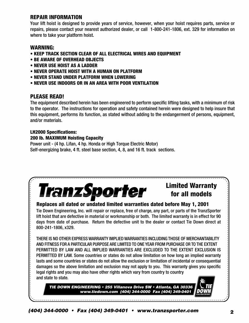
LH2000 Specifications:200 lb. MAXIMUM Hoisting CapacityPower unit - (4 hp. Lifan, 4 hp. Honda or High Torque Electric Motor)Self-energizing brake, 4 ft. steel base section, 4, 8, and 16 ft. track sections.
Replaces all dated or undated limited warranties dated before May 1, 2001 Tie Down Engineering, Inc. will repair or replace, free of charge, any part, or parts of the TranzSporter lift hoist that are defective in material or workmanship or both. The limited warranty is in effect for 90 days from date of purchase. Return the defective unit to the dealer or contact Tie Down direct at 800-241-1806, x329.
THERE IS NO OTHER EXPRESS WARRANTY IMPLIED WARRANTIES INCLUDING THOSE OF MERCHANTABILITY AND FITNESS FOR A PARTICULAR PURPOSE ARE LIMITED TO ONE YEAR FROM PURCHASE OR TO THE EXTENT PERMITTED BY LAW AND ALL IMPLIED WARRANTIES ARE EXCLUDED TO THE EXTENT EXCLUSION IS PERMITTED BY LAW. Some countries or states do not allow limitation on how long an implied warranty lasts and some countries or states do not allow the exclusion or limitation of incidental or consequential damages so the above limitation and exclusion may not apply to you. This warranty gives you specific legal rights and you may also have other rights which vary from country to countryand state to state.
Limited Warranty for all models
TIE DOWN ENGINEERING • 255 Villanova Drive SW • Atlanta, GA 30336www.tiedown.com (404) 344-0000 Fax (404) 349-0401
Tie Down Engineering • 255 Villanova Dr. SW • Atlanta, Georgia 303363
Safety instructionsCAUTION: Please read the safety warnings and Instructions contained in this manual beforeoperating the lift hoist. Failure to obey the warnings contained herein could result inpersonal injury or damage to the equipment; however, this information should not be a substitute for routine accident prevention, but rather an addition to routine accident prevention.
GENERAL SAFETY INSTRUCTIONS:1. Transport and handle your lift hoist with care.2. Unpack the TranzSporter carefully and inspect for any damage that may occur during transportation. DO NOT USE THE HOIST IF ANY PART IS DAMAGED3. Please observe all safety and warning labels attached to the hoist.4. Use only replacement parts furnished by the manufacturer.5. Always keep the area around the base section of the TranzSporter hoist clear to help prevent slipping, tripping or falling against the hoist.6. DO NOT ALLOW ANYONE TO OPERATE THE TRANZSPORTER HOIST WHO HAS NOT BEEN THOROUGHLY AND PROPERLY TRAINED IN THE CORRECT OPERATION AND USE OF THIS HOIST.7. This hoist is manufactured to lift materials only. Do not use the lift hoist for the purpose of transporting personnel from one level to another.8. Do not climb the LH-Series hoist or use as a personnel ladder.9. Do not overload - maximum lifting capacity for the LH-200 & LH-2000 is 200 lbs. with a load capacity of 180 lbs. Maximum lifting capacity for the LH-400 is 400 lbs. with a load capacity of 380 lbs.10. Keep hands, feet and other body parts as well as clothing away from the track sections and moving or rotating parts of the LH-Series hoist when starting the engine or when operating the hoist.11. Do not allow any persons to walk or work under or near the LH-Series hoist while in operation.12. Do not use this hoist to transport hot asphalt or any other hot molten substance from one elevation to another.13. Store all parts of the LH-Series hoist in such a fashion as not to damage any of the components.14. Do not operate indoors or in an area with poor ventilation.
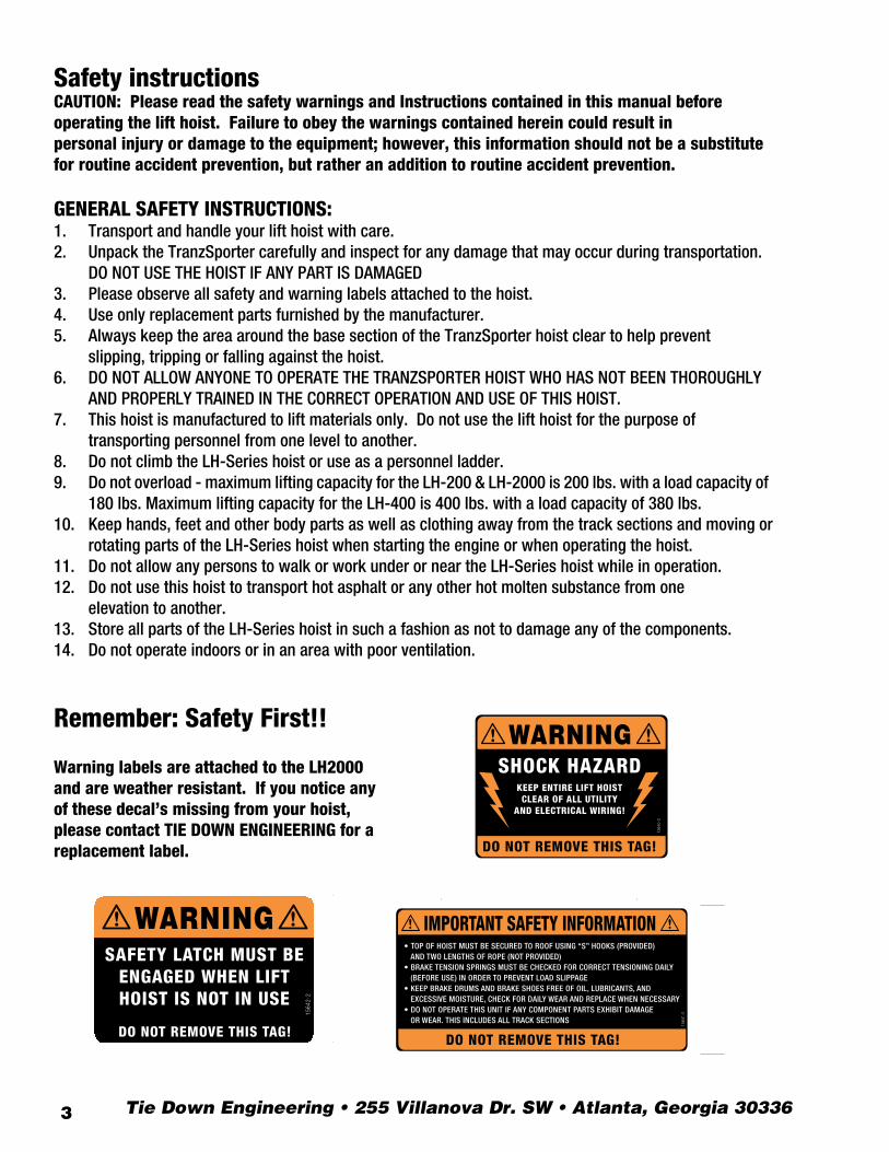
Warning labels are attached to the LH2000 and are weather resistant. If you notice any of these decal’s missing from your hoist, please contact TIE DOWN ENGINEERING for a replacement label.
Remember: Safety First!!
1564
0-2
WARNING
DO NOT REMOVE THIS TAG!
SHOCK HAZARDKEEP ENTIRE LIFT HOISTCLEAR OF ALL UTILITY
AND ELECTRICAL WIRING!
1564
1-2
DO NOT REMOVE THIS TAG!
IMPORTANT SAFETY INFORMATION• TOP OF HOIST MUST BE SECURED TO ROOF USING “S” HOOKS (PROVIDED) AND TWO LENGTHS OF ROPE (NOT PROVIDED)• BRAKE TENSION SPRINGS MUST BE CHECKED FOR CORRECT TENSIONING DAILY (BEFORE USE) IN ORDER TO PREVENT LOAD SLIPPAGE• KEEP BRAKE DRUMS AND BRAKE SHOES FREE OF OIL, LUBRICANTS, AND EXCESSIVE MOISTURE, CHECK FOR DAILY WEAR AND REPLACE WHEN NECESSARY• DO NOT OPERATE THIS UNIT IF ANY COMPONENT PARTS EXHIBIT DAMAGE OR WEAR. THIS INCLUDES ALL TRACK SECTIONS
WARNINGSAFETY LATCH MUST BE
ENGAGED WHEN LIFTHOIST IS NOT IN USE
DO NOT REMOVE THIS TAG!
1564
2-2
1564
0-2
WARNING
DO NOT REMOVE THIS TAG!
SHOCK HAZARDKEEP ENTIRE LIFT HOISTCLEAR OF ALL UTILITY
AND ELECTRICAL WIRING!
1564
1-2
DO NOT REMOVE THIS TAG!
IMPORTANT SAFETY INFORMATION• TOP OF HOIST MUST BE SECURED TO ROOF USING “S” HOOKS (PROVIDED) AND TWO LENGTHS OF ROPE (NOT PROVIDED)• BRAKE TENSION SPRINGS MUST BE CHECKED FOR CORRECT TENSIONING DAILY (BEFORE USE) IN ORDER TO PREVENT LOAD SLIPPAGE• KEEP BRAKE DRUMS AND BRAKE SHOES FREE OF OIL, LUBRICANTS, AND EXCESSIVE MOISTURE, CHECK FOR DAILY WEAR AND REPLACE WHEN NECESSARY• DO NOT OPERATE THIS UNIT IF ANY COMPONENT PARTS EXHIBIT DAMAGE OR WEAR. THIS INCLUDES ALL TRACK SECTIONS
WARNINGSAFETY LATCH MUST BE
ENGAGED WHEN LIFTHOIST IS NOT IN USE
DO NOT REMOVE THIS TAG!
1564
2-2
(404) 344-0000 • Fax (404) 349-0401 • www.tranzsporter.com 4
Assembly Instructions LH2000 Hoist
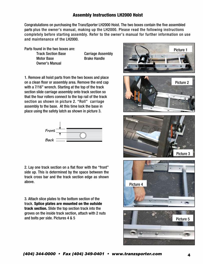
Congratulations on purchasing the TranzSporter LH2000 Hoist. The two boxes contain the five assembled parts plus the owner’s manual, making up the LH2000. Please read the following instructions completely before starting assembly. Refer to the owner’s manual for further information on use and maintenance of the LH2000.
Parts found in the two boxes are: Track Section Base Carriage Assembly Motor Base Brake Handle Owner’s Manual
2. Lay one track section on a flat floor with the “front” side up. This is determined by the space between the track cross bar and the track section edge as shown above.
3. Attach slice plates to the bottom section of the track. Splice plates are mounted on the outside track section. Slide the top section track into the groves on the inside track section, attach with 2 nuts and bolts per side. Pictures 4 & 5
Picture 1
Front
Back
Picture 2
Picture 3
Picture 4
Picture 5
1. Remove all hoist parts from the two boxes and place on a clean floor or assembly area. Remove the end cap with a 7/16” wrench. Starting at the top of the track section slide carriage assembly onto track section so that the four rollers connect to the top rail of the track section as shown in picture 2. “Roll” carriage assembly to the base. At this time lock the base in place using the safety latch as shown in picture 3.
Tie Down Engineering • 255 Villanova Dr. SW • Atlanta, Georgia 303365
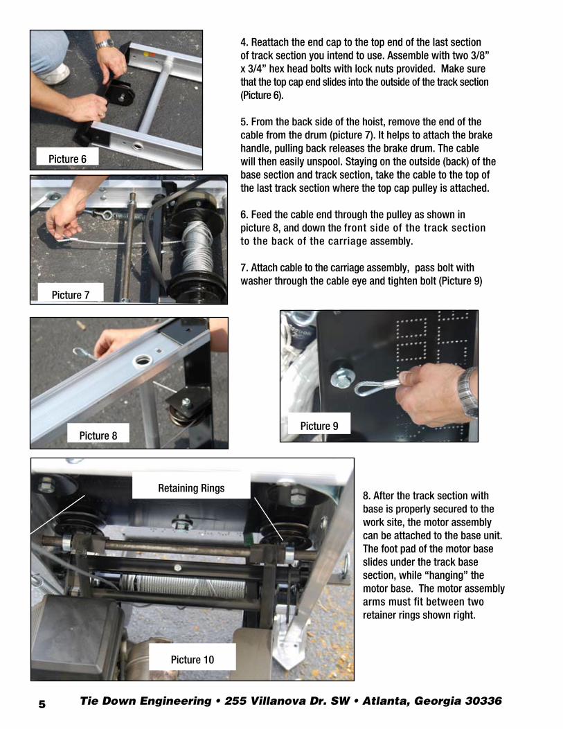
8. After the track section with base is properly secured to the work site, the motor assembly can be attached to the base unit. The foot pad of the motor base slides under the track basesection, while “hanging” the motor base. The motor assembly arms must fit between tworetainer rings shown right.
4. Reattach the end cap to the top end of the last section of track section you intend to use. Assemble with two 3/8” x 3/4” hex head bolts with lock nuts provided. Make sure that the top cap end slides into the outside of the track section(Picture 6).
5. From the back side of the hoist, remove the end of the cable from the drum (picture 7). It helps to attach the brake handle, pulling back releases the brake drum. The cable will then easily unspool. Staying on the outside (back) of the base section and track section, take the cable to the top of the last track section where the top cap pulley is attached.
6. Feed the cable end through the pulley as shown inpicture 8, and down the front side of the track section to the back of the carriage assembly.
7. Attach cable to the carriage assembly, pass bolt with washer through the cable eye and tighten bolt (Picture 9)
Picture 6
Picture 7
Picture 8
Picture 10
Picture 9
Retaining Rings
(404) 344-0000 • Fax (404) 349-0401 • www.tranzsporter.com 6
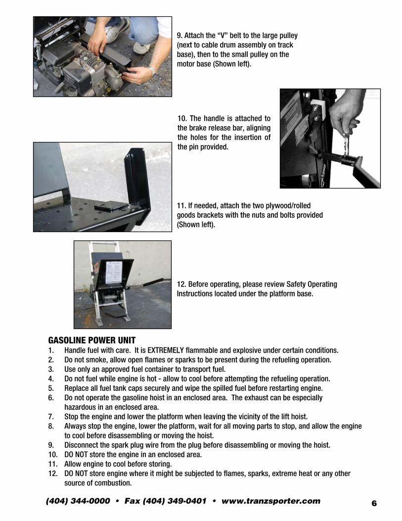
GASOLINE POWER UNIT1. Handle fuel with care. It is EXTREMELY flammable and explosive under certain conditions.2. Do not smoke, allow open flames or sparks to be present during the refueling operation.3. Use only an approved fuel container to transport fuel.4. Do not fuel while engine is hot - allow to cool before attempting the refueling operation.5. Replace all fuel tank caps securely and wipe the spilled fuel before restarting engine.6. Do not operate the gasoline hoist in an enclosed area. The exhaust can be especially hazardous in an enclosed area.7. Stop the engine and lower the platform when leaving the vicinity of the lift hoist.8. Always stop the engine, lower the platform, wait for all moving parts to stop, and allow the engine to cool before disassembling or moving the hoist.9. Disconnect the spark plug wire from the plug before disassembling or moving the hoist.10. DO NOT store the engine in an enclosed area.11. Allow engine to cool before storing.12. DO NOT store engine where it might be subjected to flames, sparks, extreme heat or any other source of combustion.
9. Attach the “V” belt to the large pulley (next to cable drum assembly on track base), then to the small pulley on the motor base (Shown left).
12. Before operating, please review Safety OperatingInstructions located under the platform base.
11. If needed, attach the two plywood/rolled goods brackets with the nuts and bolts provided (Shown left).
10. The handle is attached to the brake release bar, aligning the holes for the insertion of the pin provided.
Tie Down Engineering • 255 Villanova Dr. SW • Atlanta, Georgia 303367
Raising the Track Section Assembly
WARNING: KEEP TRACK SECTIONS CLEAR OF ALL ELECTRICAL WIRES AND EQUIPMENTBE AWARE OF OVERHEAD OBJECTS-NEVER CLIMB HOIST!The hoist assembly is extremely top heavy and must be kept under control at all times.Two alternate methods are suggested for raising the platform hoist to the operating position.
PROCEDURE “A” This procedure requires two or preferably three men.1. Lay the assembled track sections with the platform attached parallel to the building wall that is to support the hoist.2. Tie a rope to the head bracket and have the man on roof pull up the hoist while the other man on the ground braces the shoes on the bottom section to prevent slippage of the hoist shoes. The third man on the ground may aid in erecting by “walking” the hoist up hand over hand by the rungs.3. When the hoist reaches a vertical position, carefully turn the hoist 90 degrees with the platform pointing away from the building. Move the bottom of the hoist away from the building, 1/4 of the height of the building where the top of the hoist is to be supported. Make allowances for overhang. See track section support chart for approximate distances of the base from the bottom track.
ALTERNATE PROCEDURE “B”1. Place track section assembly perpendicular to the building with the bottom shoes of the steel bottom section resting against the building to prevent slipping.2. Tie a rope to the head bracket and have the man on the roof pull up the hoist while the other man on the ground braces the shoes on the steel bottom section to prevent slippage of the hoist shoes. The third man on the ground may aid in erecting by “walking” the hoist up hand over hand by the rungs.3. When the hoist reaches a vertical position, carefully turn the hoist 180 degrees with the platform pointing away from the building. Move the bottom of the hoist away from the building, 1/4 of the height of the building where the top of the hoist is to be supported. Angle of track sections from building should be between 18 and 20 degrees. Make allowances for an overhang. See Track Section Chart for approximate distances of the base from the building.
AFTER ERECTING THE HOIST USING PROCEDURE “A” OR “B”, CONTINUE AS FOLLOWS:
4. Tie the track section to the roof with a rope fastened to a cross tie on the top bracket to prevent slippage of the track section. DO NOT TIE ROPE TO THE RAILS - THIS WILL PREVENT THE PLATFORM FROM OPERATING PROPERLY.5. Mount the power unit to the top rung of the steel bottom section. Attach the V-belt to the pulley on the power unit.Slide the brake handle over the brake arm and install the pin provided.6. Remove any ropes used to secure the platform during transportation.7. Make certain the shoes on the steel bottom section are firmly resting on level ground. This will help to prevent track section slippage or uneven loading of the track section which could cause damage or injury to personnel and/or to equipment.
(404) 344-0000 • Fax (404) 349-0401 • www.tranzsporter.com 8
WARNING: BEFORE LOWERING THE TRACK SECTIONS, CAREFULLY CHECK FOROVERHEAD OBJECTS AND POWER LINES.
Raising the platform with or without loadWARNING: THE OPERATOR OF THIS HOIST UNIT SHOULD WEAR APPROPRIATE SAFETY EQUIPMENT WHICH SHOULD INCLUDE APPROVED HAND PROTECTION, HEAD PROTECTION AND EYE PROTECTION.
To raise the platform on the lift hoist, face the platform and stand as far as possible from the hoist tooperate. Place your foot on the foot control brace to engage the motor to drum belt, permitting the platform to roll up the track section. When the platform reaches the top, release foot IMMEDIATELY. This will apply the self energizing brake. Move away from the hoist while the load is being removed from the platform.
Lowering the platformTo lower the carriage, stand to the right or left side of the hoist and grasp the brake handle. Lightly feather the platform down by engaging and disengaging the brake to slow the carriage. Lower the carriage to the ground at a slow speed (not to exceed 50/feet per minute). Continue to decelerate the platform as it nears the ground to prevent damage to the platform or bottom brace stops.
CAUTION: NEVER APPLY THE BRAKE ABRUPTLY - BROKEN HOIST CABLES AND/OR SEVERE INJURY TO PERSONNEL OR EQUIPMENT MAY OCCUR. MAKE CERTAIN PLATFORM DOES NOT STRIKE THE BOTTOM BRACE STOPS UPON REACHING THE BOTTOM OF THE TRACK SECTION.
Lower and dismantle the platform hoist assembly in the reverse of the erection procedure, observing all safety procedures.
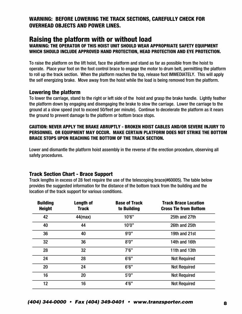
Track Section Chart - Brace SupportTrack lengths in excess of 28 feet require the use of the telescoping brace(#60005). The table belowprovides the suggested information for the distance of the bottom track from the building and thelocation of the track support for various conditions.
Building Length of Base of Track Track Brace Location Height Track to Building Cross Tie from Bottom
42 44(max) 10’6” 25th and 27th
40 44 10’0” 26th and 25th
36 40 9’0” 19th and 21st
32 36 8’0” 14th and 16th
28 32 7’6” 11th and 13th
24 28 6’6” Not Required
20 24 6’6” Not Required
16 20 5’0” Not Required
12 16 4’6” Not Required
LH
-20
00
Pa
rts
De
tail L
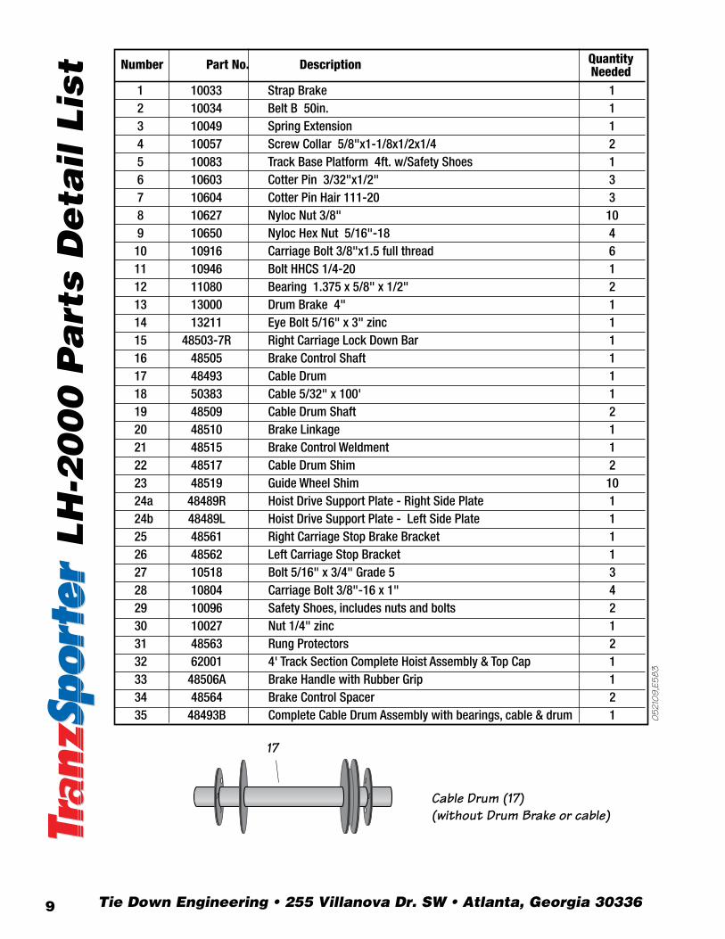
ist Number Part No. Description Quantity
Needed 1 10033 Strap Brake 1 2 10034 Belt B 50in. 1 3 10049 Spring Extension 1 4 10057 Screw Collar 5/8"x1-1/8x1/2x1/4 2 5 10083 Track Base Platform 4ft. w/Safety Shoes 1 6 10603 Cotter Pin 3/32"x1/2" 3 7 10604 Cotter Pin Hair 111-20 3 8 10627 Nyloc Nut 3/8" 10 9 10650 Nyloc Hex Nut 5/16"-18 410 10916 Carriage Bolt 3/8"x1.5 full thread 611 10946 Bolt HHCS 1/4-20 112 11080 Bearing 1.375 x 5/8" x 1/2" 213 13000 Drum Brake 4" 114 13211 Eye Bolt 5/16" x 3" zinc 115 48503-7R Right Carriage Lock Down Bar 116 48505 Brake Control Shaft 117 48493 Cable Drum 118 50383 Cable 5/32" x 100' 1 19 48509 Cable Drum Shaft 220 48510 Brake Linkage 121 48515 Brake Control Weldment 122 48517 Cable Drum Shim 223 48519 Guide Wheel Shim 1024a 48489R Hoist Drive Support Plate - Right Side Plate 124b 48489L Hoist Drive Support Plate - Left Side Plate 125 48561 Right Carriage Stop Brake Bracket 126 48562 Left Carriage Stop Bracket 127 10518 Bolt 5/16" x 3/4" Grade 5 328 10804 Carriage Bolt 3/8"-16 x 1" 429 10096 Safety Shoes, includes nuts and bolts 230 10027 Nut 1/4" zinc 131 48563 Rung Protectors 232 62001 4' Track Section Complete Hoist Assembly & Top Cap 1 33 48506A Brake Handle with Rubber Grip 134 48564 Brake Control Spacer 235 48493B Complete Cable Drum Assembly with bearings, cable & drum 1
19
19
3 24a
24b
5
8
7
7 33
8
1
2
23x2
9 8
15
23
10
25
4
4 10
10 26
23
28
16
21
11
30
28
34
34
8
14
28
29
29
8
6 20
6
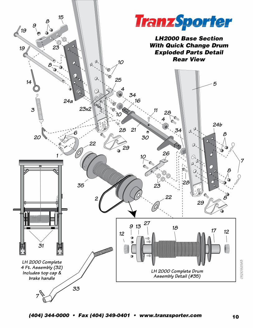
LH 2000 Complete 4 Ft. Assembly (32) Includes top cap &
brake handle
LH2000 Base SectionWith Quick Change Drum
Exploded Parts DetailRear View
22
22
052
109,
E58
3
052
109,
E58
3
31
35
17
Cable Drum (17)(without Drum Brake or cable)
18 12 17
27 13 9 12
LH 2000 Complete Drum Assembly Detail (#35)
Tie Down Engineering • 255 Villanova Dr. SW • Atlanta, Georgia 303369
(404) 344-0000 • Fax (404) 349-0401 • www.tranzsporter.com 10
LH
-20
00
Pa
rts
De
tail L
ist Number Part No. Description Quantity
Needed 1 10033 Strap Brake 1 2 10034 Belt B 50in. 1 3 10049 Spring Extension 1 4 10057 Screw Collar 5/8"x1-1/8x1/2x1/4 2 5 10083 Track Base Platform 4ft. w/Safety Shoes 1 6 10603 Cotter Pin 3/32"x1/2" 3 7 10604 Cotter Pin Hair 111-20 3 8 10627 Nyloc Nut 3/8" 10 9 10650 Nyloc Hex Nut 5/16"-18 410 10916 Carriage Bolt 3/8"x1.5 full thread 611 10946 Bolt HHCS 1/4-20 112 11080 Bearing 1.375 x 5/8" x 1/2" 213 13000 Drum Brake 4" 114 13211 Eye Bolt 5/16" x 3" zinc 115 48503-7R Right Carriage Lock Down Bar 116 48505 Brake Control Shaft 117 48493 Cable Drum 118 50383 Cable 5/32" x 100' 1 19 48509 Cable Drum Shaft 220 48510 Brake Linkage 121 48515 Brake Control Weldment 122 48517 Cable Drum Shim 223 48519 Guide Wheel Shim 1024a 48489R Hoist Drive Support Plate - Right Side Plate 124b 48489L Hoist Drive Support Plate - Left Side Plate 125 48561 Right Carriage Stop Brake Bracket 126 48562 Left Carriage Stop Bracket 127 10518 Bolt 5/16" x 3/4" Grade 5 328 10804 Carriage Bolt 3/8"-16 x 1" 429 10096 Safety Shoes, includes nuts and bolts 230 10027 Nut 1/4" zinc 131 48563 Rung Protectors 232 62001 4' Track Section Complete Hoist Assembly & Top Cap 1 33 48506A Brake Handle with Rubber Grip 134 48564 Brake Control Spacer 235 48493B Complete Cable Drum Assembly with bearings, cable & drum 1
19
19
3 24a
24b
5
8
7
7 33
8
1
2
23x2
9 8
15
23
10
25
4
4 10
10 26
23
28
16
21
11
30
28
34
34
8
14
28
29
29
8
6 20
6
LH 2000 Complete 4 Ft. Assembly (32) Includes top cap &
brake handle
LH2000 Base SectionWith Quick Change Drum
Exploded Parts DetailRear View
22
22
052
109,
E58
3
052
109,
E58
331
35
17
Cable Drum (17)(without Drum Brake or cable)
18 12 17
27 13 9 12
LH 2000 Complete Drum Assembly Detail (#35)
Tie Down Engineering • 255 Villanova Dr. SW • Atlanta, Georgia 3033611
1104
09,E
600
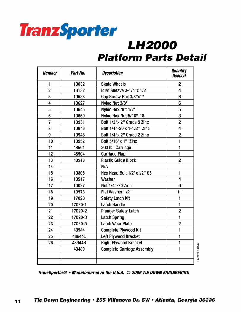
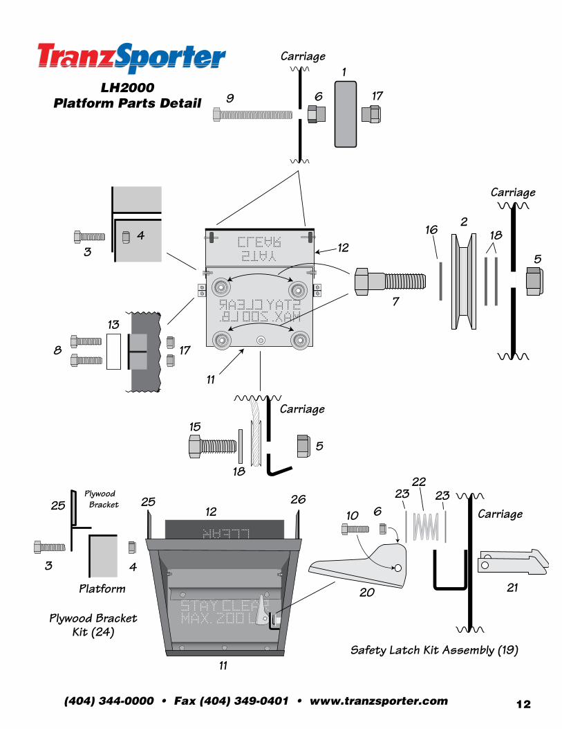
LH2000Platform Parts Detail
Number Part No. Description Quantity Needed
1 10032 Skate Wheels 22 13132 Idler Sheave 3-1/4"x 1/2 43 10538 Cap Screw Hex 3/8"x1" 64 10627 Nyloc Nut 3/8" 65 10645 Nyloc Hex Nut 1/2" 56 10650 Nyloc Hex Nut 5/16"-18 37 10931 Bolt 1/2"x 2" Grade 5 Zinc 28 10946 Bolt 1/4"-20 x 1-1/2" Zinc 49 10948 Bolt 1/4"x 2" Grade 2 Zinc 210 10952 Bolt 5/16"x 1" Zinc 111 48501 200 lb. Carriage 112 48504 Carriage Flap 113 48513 Plastic Guide Block 214 N/A 15 10806 Hex Head Bolt 1/2"x1/2" G5 116 10517 Washer 417 10027 Nut 1/4"-20 Zinc 618 10573 Flat Washer 1/2" 1119 17020 Safety Latch Kit 120 17020-1 Latch Handle 121 17020-2 Plunger Safety Latch 222 17020-3 Latch Spring 123 17020-5 Latch Wear Plate 224 48944 Complete Plywood Kit 125 48944L Left Plywood Bracket 126 48944R Right Plywood Bracket 1 48480 Complete Carriage Assembly 1
Carriage
Plywood Bracket
Carriage
Carriage
Carriage
Platform
9
3 4
6
1
17
7
2
11
12
11
12 25 25
3 4
26
5
18
20
10 6 23
5
18
15
17 8
13
22 23
21
16
LH2000Platform Parts Detail
TranzSporter® • Manufactured in the U.S.A. © 2006 TIE DOWN ENGINEERING Safety Latch Kit Assembly (19)
Plywood Bracket Kit (24)
(404) 344-0000 • Fax (404) 349-0401 • www.tranzsporter.com 12
1104
09,E
600
LH2000Platform Parts Detail
Number Part No. Description Quantity Needed
1 10032 Skate Wheels 22 13132 Idler Sheave 3-1/4"x 1/2 43 10538 Cap Screw Hex 3/8"x1" 64 10627 Nyloc Nut 3/8" 65 10645 Nyloc Hex Nut 1/2" 56 10650 Nyloc Hex Nut 5/16"-18 37 10931 Bolt 1/2"x 2" Grade 5 Zinc 28 10946 Bolt 1/4"-20 x 1-1/2" Zinc 49 10948 Bolt 1/4"x 2" Grade 2 Zinc 210 10952 Bolt 5/16"x 1" Zinc 111 48501 200 lb. Carriage 112 48504 Carriage Flap 113 48513 Plastic Guide Block 214 N/A 15 10806 Hex Head Bolt 1/2"x1/2" G5 116 10517 Washer 417 10027 Nut 1/4"-20 Zinc 618 10573 Flat Washer 1/2" 1119 17020 Safety Latch Kit 120 17020-1 Latch Handle 121 17020-2 Plunger Safety Latch 222 17020-3 Latch Spring 123 17020-5 Latch Wear Plate 224 48944 Complete Plywood Kit 125 48944L Left Plywood Bracket 126 48944R Right Plywood Bracket 1 48480 Complete Carriage Assembly 1
Carriage
Plywood Bracket
Carriage
Carriage
Carriage
Platform
9
3 4
6
1
17
7
2
11
12
11
12 25 25
3 4
26
5
18
20
10 6 23
5
18
15
17 8
13
22 23
21
16
LH2000Platform Parts Detail
TranzSporter® • Manufactured in the U.S.A. © 2006 TIE DOWN ENGINEERING Safety Latch Kit Assembly (19)
Plywood Bracket Kit (24)
11030
9,E1
08
0
2
13
68
9
11
3
10
10
11
11
11
10
Number Part No. Description QuantityNeeded
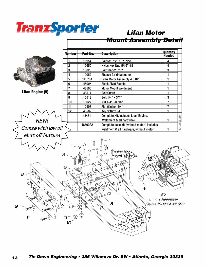
1 10954 Bolt 5/16"x1-1/2" Zinc 42 10650 Nyloc Hex Nut 5/16"-18 43 10026 Bolt 1/4"-20 x 3" 34 10052 Sheave for drive motor 15 12570A Lifan Motor Assembly 4.0 HP 16 45005 Block Pivot Saddle 17 48500 Motor Mount Weldment 18 48514 Belt Guard 19 10518 Bolt 1/4" x 3/4" 310 10027 Nut 1/4"-20 Zinc 711 10507 Flat Washer 1/4" 712 48502 Key 3/16"x3/4 1 48471 Complete Kit, includes Lifan Engine, Weldment & all hardware 1 48500AA Complete base kit (without motor), includes weldment & all hardware, without motor 1
7
Lifan Engine (5)
Lifan MotorMount Assembly Detail
4
12Engine blockmounting bolts
#5Engine Assembly
Includes 10037 & 48502
NEW!Comes with low oil
shut off feature
1107
03,6
02
1003
09,E
602
2
1 3
6 8
9
11
3
10
10
11
11
11
10
Number Part No. Description Quantity Needed
1 10954 Bolt 5/16"x1-1/2" Zinc 4 2 10650 Nyloc Hex Nut 5/16"-18 4 3 10026 Bolt 1/4"-20 x 3" Grade 2 3 4 10037 Sheave for drive motor 1 5 12559A Briggs & Stratton Motor Assembly 4.0 HP 1 6 45005 Block Pivot Saddle 1 7 48500 Motor Mount Weldment 1 8 48514 Belt Guard 1 9 BBB2500075 Bolt 1/4" x 3/4" Grade 2 3 10 10027 Nut 1/4"-20 Zinc 7 11 10507 Flat Washer 1/4" 7 12 48502 Key 3/16"x3/4 1 48470 Complete Kit, includes Briggs Engine, Weldment & all hardware 1 48500AA Complete base kit (without motor), includes weldment & all hardware, without motor 1
7
Briggs & Stratton Engine (5)
Briggs & Stratton Motor Mount Assembly Detail
4
12 Engine block mounting bolts
#5 Engine Assembly
Includes 10037 & 48502
#5Engine Assembly
Includes 10052 & 48502
7
1
3
6 10
12
14
13
14
14
14
13
3
11
Number Part No. Description Quantity Needed
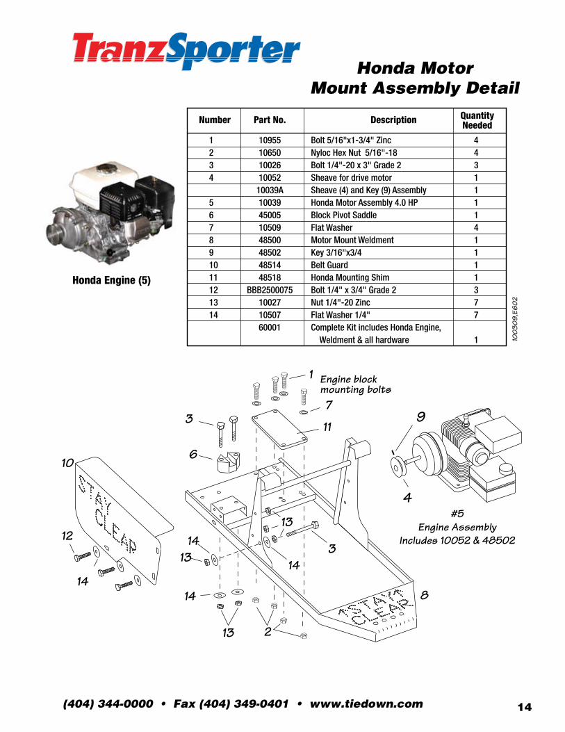
1 10955 Bolt 5/16"x1-3/4" Zinc 42 10650 Nyloc Hex Nut 5/16"-18 43 10026 Bolt 1/4"-20 x 3" Grade 2 34 10052 Sheave for drive motor 1 10039A Sheave (4) and Key (9) Assembly 15 10039 Honda Motor Assembly 4.0 HP 16 45005 Block Pivot Saddle 17 10509 Flat Washer 48 48500 Motor Mount Weldment 19 48502 Key 3/16"x3/4 110 48514 Belt Guard 111 48518 Honda Mounting Shim 112 BBB2500075 Bolt 1/4" x 3/4" Grade 2 313 10027 Nut 1/4"-20 Zinc 714 10507 Flat Washer 1/4" 7 60001 Complete Kit includes Honda Engine, Weldment & all hardware 1
8
Honda Engine (5)
Honda Motor Mount Assembly Detail
2
4
9
Engine block mounting bolts
13
Tie Down Engineering • 255 Villanova Dr. SW • Atlanta, Georgia 3033613
1107
03,6
02
1003
09,E
602
2
1 3
6 8
9
11
3
10
10
11
11
11
10
Number Part No. Description Quantity Needed
1 10954 Bolt 5/16"x1-1/2" Zinc 4 2 10650 Nyloc Hex Nut 5/16"-18 4 3 10026 Bolt 1/4"-20 x 3" Grade 2 3 4 10037 Sheave for drive motor 1 5 12559A Briggs & Stratton Motor Assembly 4.0 HP 1 6 45005 Block Pivot Saddle 1 7 48500 Motor Mount Weldment 1 8 48514 Belt Guard 1 9 BBB2500075 Bolt 1/4" x 3/4" Grade 2 3 10 10027 Nut 1/4"-20 Zinc 7 11 10507 Flat Washer 1/4" 7 12 48502 Key 3/16"x3/4 1 48470 Complete Kit, includes Briggs Engine, Weldment & all hardware 1 48500AA Complete base kit (without motor), includes weldment & all hardware, without motor 1
7
Briggs & Stratton Engine (5)
Briggs & Stratton Motor Mount Assembly Detail
4
12 Engine block mounting bolts
#5 Engine Assembly
Includes 10037 & 48502
#5Engine Assembly
Includes 10052 & 48502
7
1
3
6 10
12
14
13
14
14
14
13
3
11
Number Part No. Description Quantity Needed
1 10955 Bolt 5/16"x1-3/4" Zinc 42 10650 Nyloc Hex Nut 5/16"-18 43 10026 Bolt 1/4"-20 x 3" Grade 2 34 10052 Sheave for drive motor 1 10039A Sheave (4) and Key (9) Assembly 15 10039 Honda Motor Assembly 4.0 HP 16 45005 Block Pivot Saddle 17 10509 Flat Washer 48 48500 Motor Mount Weldment 19 48502 Key 3/16"x3/4 110 48514 Belt Guard 111 48518 Honda Mounting Shim 112 BBB2500075 Bolt 1/4" x 3/4" Grade 2 313 10027 Nut 1/4"-20 Zinc 714 10507 Flat Washer 1/4" 7 60001 Complete Kit includes Honda Engine, Weldment & all hardware 1
8
Honda Engine (5)
Honda Motor Mount Assembly Detail
2
4
9
Engine block mounting bolts
13
(404) 344-0000 • Fax (404) 349-0401 • www.tiedown.com 14
0518
09,E
601
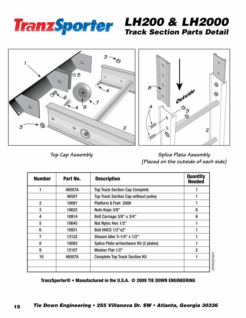
Number Part No. Description Quantity Needed
1 48507A Top Track Section Cap Complete 1
48507 Top Track Section Cap without pulley 1
2 10091 Platform 8 Feet 200# 1
3 10622 Nuts Keps 3/8" 6
4 10914 Bolt Carriage 3/8" x 3/4" 6
5 10645 Nut Nyloc Hex 1/2" 1
6 10931 Bolt HHCS 1/2"x2" 1
7 13132 Sheave Idler 3-1/4" x 1/2" 1
8 10093 Splice Plate w/hardware Kit (2 plates) 1
9 12107 Washer Flat 1/2" 2
10 48507A Complete Top Track Section Kit 1
1
3
4
5
6 7
9
4
3
2
LH200 & LH2000Track Section Parts Detail
TranzSporter® • Manufactured in the U.S.A. © 2009 TIE DOWN ENGINEERING
Top Cap Assembly Splice Plate Assembly (Placed on the outside of each side)
3 4
2
8
Tie Down Engineering • 255 Villanova Dr. SW • Atlanta, Georgia 3033615

