Embed Size (px)
Citation preview
ColorMax� Powder Coating BoothInstallation Guide
Customer Product ManualPart 1099290A
Issued 2/10
NORDSON CORPORATION • AMHERST, OHIO • USA
For parts and technical support, call the Finishing Customer Support Center at (800) 433-9319.
This document is subject to change without notice.Check http://emanuals.nordson.com for the latest version.
Part 1099290A � 2010 Nordson Corporation
Table of ContentsSafety 1. . . . . . . . . . . . . . . . . . . . . . . . . . . . . . . . . . . . . . .
Qualified Personnel 1. . . . . . . . . . . . . . . . . . . . . . . . .Regulations and Approvals 1. . . . . . . . . . . . . . . . . .Grounding 1. . . . . . . . . . . . . . . . . . . . . . . . . . . . . . . . .
Unloading and Storage 2. . . . . . . . . . . . . . . . . . . . . . .Unpacking 2. . . . . . . . . . . . . . . . . . . . . . . . . . . . . . . . . .Preparation 2. . . . . . . . . . . . . . . . . . . . . . . . . . . . . . . . .
Tools 2. . . . . . . . . . . . . . . . . . . . . . . . . . . . . . . . . . .Installation Location 3. . . . . . . . . . . . . . . . . . . . . . . .
Booth Base Installation-Fixed Booth 3. . . . . . . . . .Booth Base Installation-Roll On/Roll Off Booth 5.Canopy Installation 7. . . . . . . . . . . . . . . . . . . . . . . . . .
End Panel Installation 7. . . . . . . . . . . . . . . . . . . . . . .Side Panel Installation 9. . . . . . . . . . . . . . . . . . . . . .Roof Panel Installation 12. . . . . . . . . . . . . . . . . . . . . .Service Door Installation 14. . . . . . . . . . . . . . . . . . . .
Extraction Duct Installation 15. . . . . . . . . . . . . . . . . . .Cyclone Installation 17. . . . . . . . . . . . . . . . . . . . . . . . . .Cover Panel and Skirt Installation 20. . . . . . . . . . . . .Booth Seam Sealing 21. . . . . . . . . . . . . . . . . . . . . . . . .AeroDeckt Installation 21. . . . . . . . . . . . . . . . . . . . . . . .Afterfilter Installation 22. . . . . . . . . . . . . . . . . . . . . . . .Duct Installation 24. . . . . . . . . . . . . . . . . . . . . . . . . . . . .
Slip Duct Assembly Instructions 24. . . . . . . . . . . . . .Typical Ductwork Installation 25. . . . . . . . . . . . . . . . .
Fire Detector Installation 26. . . . . . . . . . . . . . . . . . . . .Booth Conditioning 27. . . . . . . . . . . . . . . . . . . . . . . . . .Completing the Installation 27. . . . . . . . . . . . . . . . . . .
Contact UsNordson Corporation welcomes requests for information, comments, andinquiries about its products. General information about Nordson can befound on the Internet using the following address:http://www.nordson.com.Address all correspondence to:
Nordson CorporationAttn: Customer Service555 Jackson StreetAmherst, OH 44001
NoticeThis is a Nordson Corporation publication which is protected by copyright.Original copyright date 2010. No part of this document may bephotocopied, reproduced, or translated to another language without theprior written consent of Nordson Corporation. The information containedin this publication is subject to change without notice.
Trademarks
Nordson, and the Nordson logo are registered trademarks of NordsonCorporation.
Apogee, ColorMax, Sure-Max, iControl, HDLV, and Prodigy are registeredtrademarks of Nordson Corporation.
AeroDeck is a trademark of Nordson Corporation.
ColorMax� Powder Coating Booth Installation 1
Part 1099290A� 2010 Nordson Corporation
ColorMax� Powder Coating Booth InstallationThis manual provides instructions and guidelines for the installation of atypical ColorMax powder coating booth. All systems are different; refer toyour system drawings.
Once the booth, cyclones, afterfilter, and ductwork is erected, your Nordsonrepresentatives will help you complete the system installation and makesure all electrical and pneumatic connections are made properly, start upthe system, and train you how to operate it properly.
Safety
Qualified Personnel Equipment owners are responsible for making sure that Nordson equipmentis installed by qualified personnel. Qualified personnel are those employeesor contractors who are trained to safely perform their assigned tasks. Theyare familiar with all relevant safety rules and regulations and are physicallycapable of performing their assigned tasks.
Regulations and Approvals Before installing any system equipment, make sure it is rated and approvedfor the environment in which it will be used. Any approvals obtained forNordson equipment will be voided if instructions for installation, operation,and service are not followed.
All phases of equipment installation must comply with all federal, state, andlocal codes. Refer to the National Fire Protection Association publicationNFPA 33 for standards on installation and operation of powder spraysystems.
Grounding Grounding inside and around the booth openings must comply with NFPArequirements for Class II Division 1 or 2 Hazardous Locations. Refer toNFPA 33, NFPA 70 (NEC articles 500, 502, and 516), and NFPA 77, latestconditions.
Equipment to be grounded includes, but is not limited to, the floor of thespray area, booth base, operator platforms, hoppers, feed center, gunpositioners, fixed gun stands, and afterfilter. Refer to the groundinginstructions in the Nordson equipment manuals for more information.
ColorMax� Powder Coating Booth Installation2
Part 1099290A � 2010 Nordson Corporation
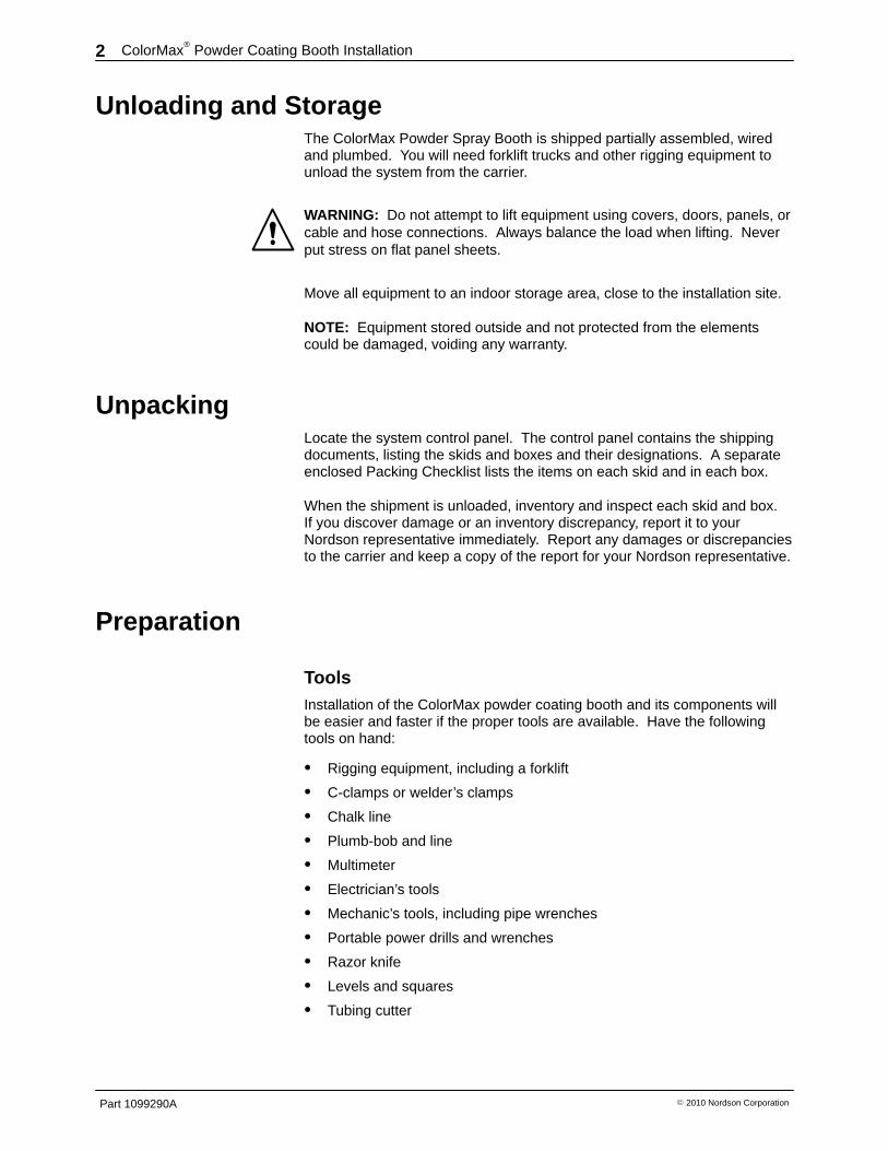
Unloading and Storage The ColorMax Powder Spray Booth is shipped partially assembled, wiredand plumbed. You will need forklift trucks and other rigging equipment tounload the system from the carrier.
WARNING: Do not attempt to lift equipment using covers, doors, panels, orcable and hose connections. Always balance the load when lifting. Neverput stress on flat panel sheets.
Move all equipment to an indoor storage area, close to the installation site.
NOTE: Equipment stored outside and not protected from the elementscould be damaged, voiding any warranty.
Unpacking Locate the system control panel. The control panel contains the shippingdocuments, listing the skids and boxes and their designations. A separateenclosed Packing Checklist lists the items on each skid and in each box.
When the shipment is unloaded, inventory and inspect each skid and box.If you discover damage or an inventory discrepancy, report it to yourNordson representative immediately. Report any damages or discrepanciesto the carrier and keep a copy of the report for your Nordson representative.
Preparation
Tools Installation of the ColorMax powder coating booth and its components willbe easier and faster if the proper tools are available. Have the followingtools on hand:
� Rigging equipment, including a forklift
� C-clamps or welder’s clamps
� Chalk line
� Plumb-bob and line
� Multimeter
� Electrician’s tools
� Mechanic’s tools, including pipe wrenches
� Portable power drills and wrenches
� Razor knife
� Levels and squares
� Tubing cutter
ColorMax� Powder Coating Booth Installation 3
Part 1099290A� 2010 Nordson Corporation
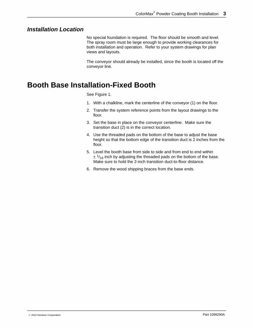
Installation Location No special foundation is required. The floor should be smooth and level.The spray room must be large enough to provide working clearances forboth installation and operation. Refer to your system drawings for planviews and layouts.
The conveyor should already be installed, since the booth is located off theconveyor line.
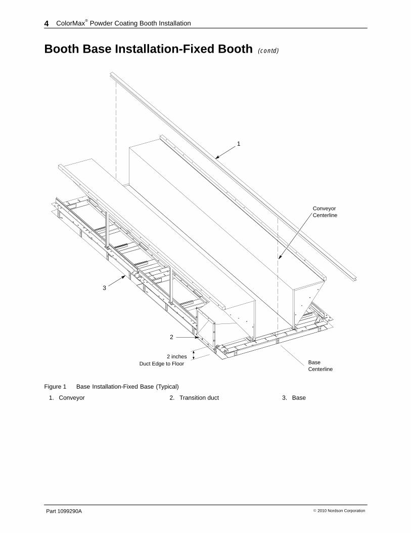
Booth Base Installation-Fixed Booth See Figure 1.
1. With a chalkline, mark the centerline of the conveyor (1) on the floor.
2. Transfer the system reference points from the layout drawings to thefloor.
3. Set the base in place on the conveyor centerline. Make sure thetransition duct (2) is in the correct location.
4. Use the threaded pads on the bottom of the base to adjust the baseheight so that the bottom edge of the transition duct is 2 inches from thefloor.
5. Level the booth base from side to side and from end to end within ± 1/16 inch by adjusting the threaded pads on the bottom of the base.Make sure to hold the 2-inch transition duct-to-floor distance.
6. Remove the wood shipping braces from the base ends.
ColorMax� Powder Coating Booth Installation4
Part 1099290A � 2010 Nordson Corporation
Booth Base Installation-Fixed Booth (contd)
2 inches
2
3
1
Duct Edge to Floor
ConveyorCenterline
BaseCenterline
Figure 1 Base Installation-Fixed Base (Typical)
1. Conveyor 2. Transition duct 3. Base
ColorMax� Powder Coating Booth Installation 5
Part 1099290A� 2010 Nordson Corporation
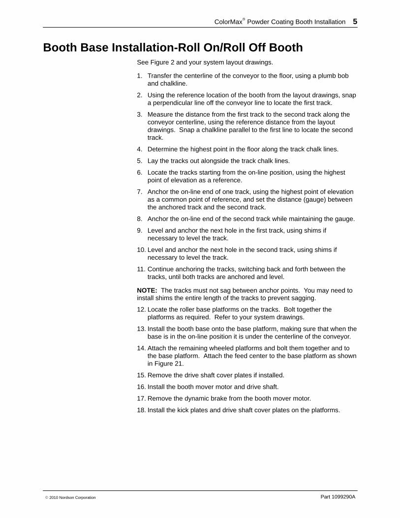
Booth Base Installation-Roll On/Roll Off Booth See Figure 2 and your system layout drawings.
1. Transfer the centerline of the conveyor to the floor, using a plumb boband chalkline.
2. Using the reference location of the booth from the layout drawings, snapa perpendicular line off the conveyor line to locate the first track.
3. Measure the distance from the first track to the second track along theconveyor centerline, using the reference distance from the layoutdrawings. Snap a chalkline parallel to the first line to locate the secondtrack.
4. Determine the highest point in the floor along the track chalk lines.
5. Lay the tracks out alongside the track chalk lines.
6. Locate the tracks starting from the on-line position, using the highestpoint of elevation as a reference.
7. Anchor the on-line end of one track, using the highest point of elevationas a common point of reference, and set the distance (gauge) betweenthe anchored track and the second track.
8. Anchor the on-line end of the second track while maintaining the gauge.
9. Level and anchor the next hole in the first track, using shims ifnecessary to level the track.
10. Level and anchor the next hole in the second track, using shims ifnecessary to level the track.
11. Continue anchoring the tracks, switching back and forth between thetracks, until both tracks are anchored and level.
NOTE: The tracks must not sag between anchor points. You may need toinstall shims the entire length of the tracks to prevent sagging.
12. Locate the roller base platforms on the tracks. Bolt together theplatforms as required. Refer to your system drawings.
13. Install the booth base onto the base platform, making sure that when thebase is in the on-line position it is under the centerline of the conveyor.
14. Attach the remaining wheeled platforms and bolt them together and tothe base platform. Attach the feed center to the base platform as shownin Figure 21.
15. Remove the drive shaft cover plates if installed.
16. Install the booth mover motor and drive shaft.
17. Remove the dynamic brake from the booth mover motor.
18. Install the kick plates and drive shaft cover plates on the platforms.
ColorMax� Powder Coating Booth Installation6
Part 1099290A � 2010 Nordson Corporation
Booth Base Installation-Roll On/Roll Off Booth (contd)
Gauge
1
2 4 5
6
7
3
9
8
On-linePosition
Figure 2 Base Installation-Roll On/Roll Off Booth (Typical)
1. Rails2. Gun positioner/iControl platform3. Booth base platform
4. Booth base5. Cyclone platform6. Drive covers
7. Drive motor and shaft8. Gun positioner/operator
platform9. Operator platform
ColorMax� Powder Coating Booth Installation 7
Part 1099290A� 2010 Nordson Corporation
Canopy Installation Unpack the Apogee� canopy panels. Inspect them for damage beforebeginning the installation. Take care not to scratch or abrade the surfacesof the panels while erecting the canopy.
When clamping the canopy panels together, do not clamp directly to thewhite panel surfaces. To avoid crushing the panels or scratching thesmooth surfaces of the panels, place the clamp jaws on the gray L-bracketsor pad the clamp jaws with flat pieces of plastic or wood.
Do not tighten the end panel or side panel fasteners until you are sure thatthe panels are level, plumb, and flush. Adjustment and shimming may berequired after the panels are installed.
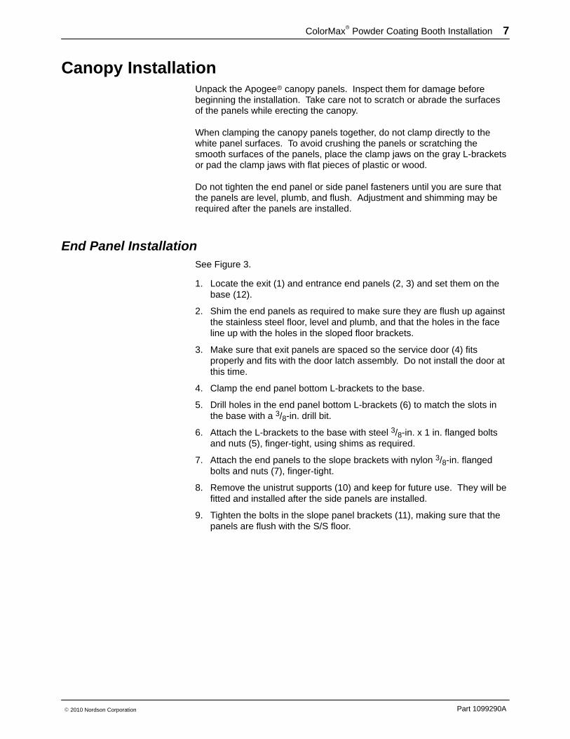
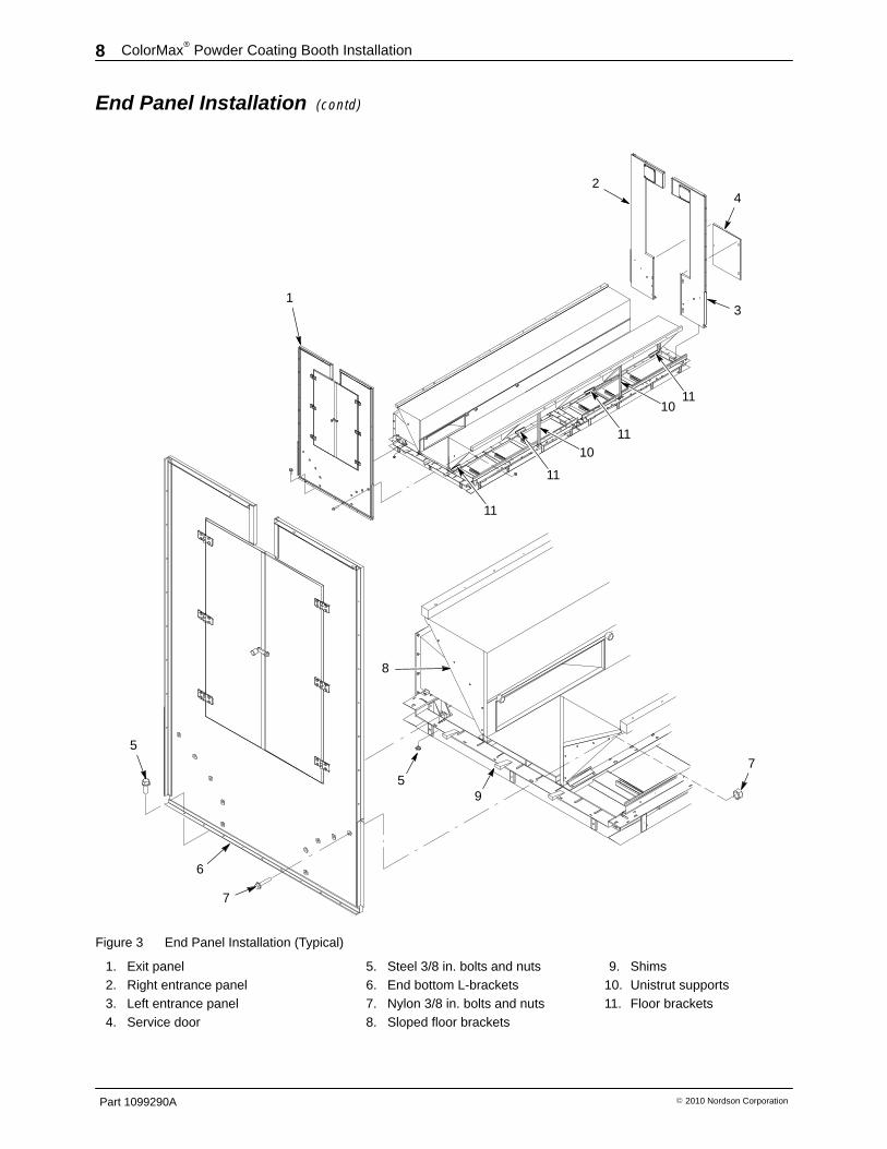
End Panel Installation See Figure 3.
1. Locate the exit (1) and entrance end panels (2, 3) and set them on thebase (12).
2. Shim the end panels as required to make sure they are flush up againstthe stainless steel floor, level and plumb, and that the holes in the faceline up with the holes in the sloped floor brackets.
3. Make sure that exit panels are spaced so the service door (4) fitsproperly and fits with the door latch assembly. Do not install the door atthis time.
4. Clamp the end panel bottom L-brackets to the base.
5. Drill holes in the end panel bottom L-brackets (6) to match the slots inthe base with a 3/8-in. drill bit.
6. Attach the L-brackets to the base with steel 3/8-in. x 1 in. flanged boltsand nuts (5), finger-tight, using shims as required.
7. Attach the end panels to the slope brackets with nylon 3/8-in. flangedbolts and nuts (7), finger-tight.
8. Remove the unistrut supports (10) and keep for future use. They will befitted and installed after the side panels are installed.
9. Tighten the bolts in the slope panel brackets (11), making sure that thepanels are flush with the S/S floor.
ColorMax� Powder Coating Booth Installation8
Part 1099290A � 2010 Nordson Corporation
End Panel Installation (contd)
2
3
4
5
1
5
6
7
8
9
7
10
10
11
11
11
11
Figure 3 End Panel Installation (Typical)
1. Exit panel2. Right entrance panel3. Left entrance panel4. Service door
5. Steel 3/8 in. bolts and nuts6. End bottom L-brackets7. Nylon 3/8 in. bolts and nuts8. Sloped floor brackets
9. Shims10. Unistrut supports11. Floor brackets
ColorMax� Powder Coating Booth Installation 9
Part 1099290A� 2010 Nordson Corporation
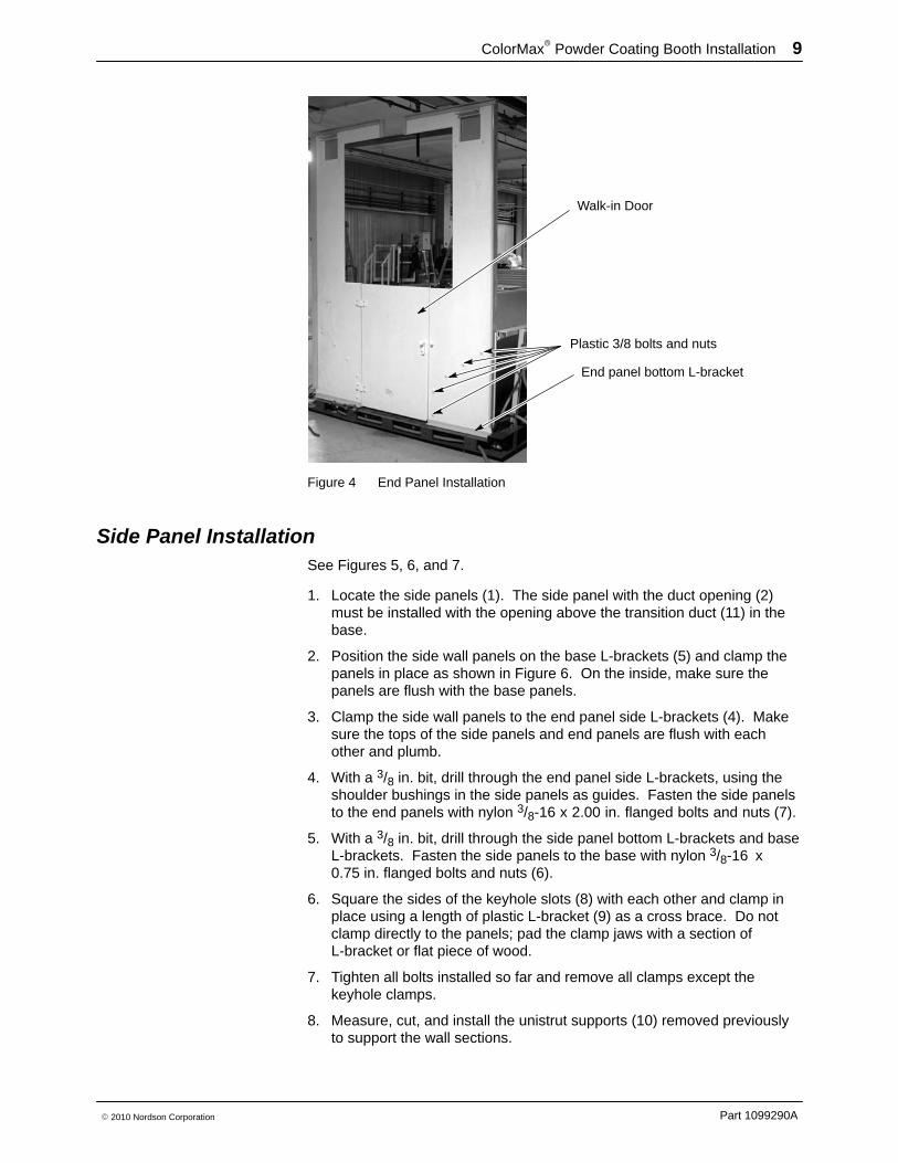
Walk-in Door
Plastic 3/8 bolts and nuts
End panel bottom L-bracket
Figure 4 End Panel Installation
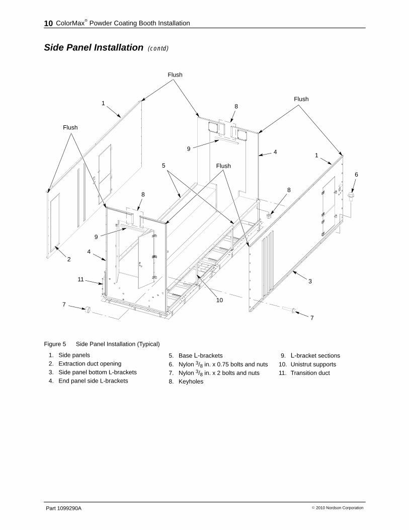
Side Panel Installation See Figures 5, 6, and 7.
1. Locate the side panels (1). The side panel with the duct opening (2)must be installed with the opening above the transition duct (11) in thebase.
2. Position the side wall panels on the base L-brackets (5) and clamp thepanels in place as shown in Figure 6. On the inside, make sure thepanels are flush with the base panels.
3. Clamp the side wall panels to the end panel side L-brackets (4). Makesure the tops of the side panels and end panels are flush with eachother and plumb.
4. With a 3/8 in. bit, drill through the end panel side L-brackets, using theshoulder bushings in the side panels as guides. Fasten the side panelsto the end panels with nylon 3/8-16 x 2.00 in. flanged bolts and nuts (7).
5. With a 3/8 in. bit, drill through the side panel bottom L-brackets and baseL-brackets. Fasten the side panels to the base with nylon 3/8-16 x0.75 in. flanged bolts and nuts (6).
6. Square the sides of the keyhole slots (8) with each other and clamp inplace using a length of plastic L-bracket (9) as a cross brace. Do notclamp directly to the panels; pad the clamp jaws with a section ofL-bracket or flat piece of wood.
7. Tighten all bolts installed so far and remove all clamps except thekeyhole clamps.
8. Measure, cut, and install the unistrut supports (10) removed previouslyto support the wall sections.
ColorMax� Powder Coating Booth Installation10
Part 1099290A � 2010 Nordson Corporation
Side Panel Installation (contd)
1
Flush
Flush
Flush
Flush
3
7
7
6
8
1
5
2
8
8
9
9
4
4
10
11
Figure 5 Side Panel Installation (Typical)
1. Side panels2. Extraction duct opening3. Side panel bottom L-brackets4. End panel side L-brackets
5. Base L-brackets
6. Nylon 3/8 in. x 0.75 bolts and nuts7. Nylon 3/8 in. x 2 bolts and nuts8. Keyholes
9. L-bracket sections
10. Unistrut supports11. Transition duct
ColorMax� Powder Coating Booth Installation 11
Part 1099290A� 2010 Nordson Corporation
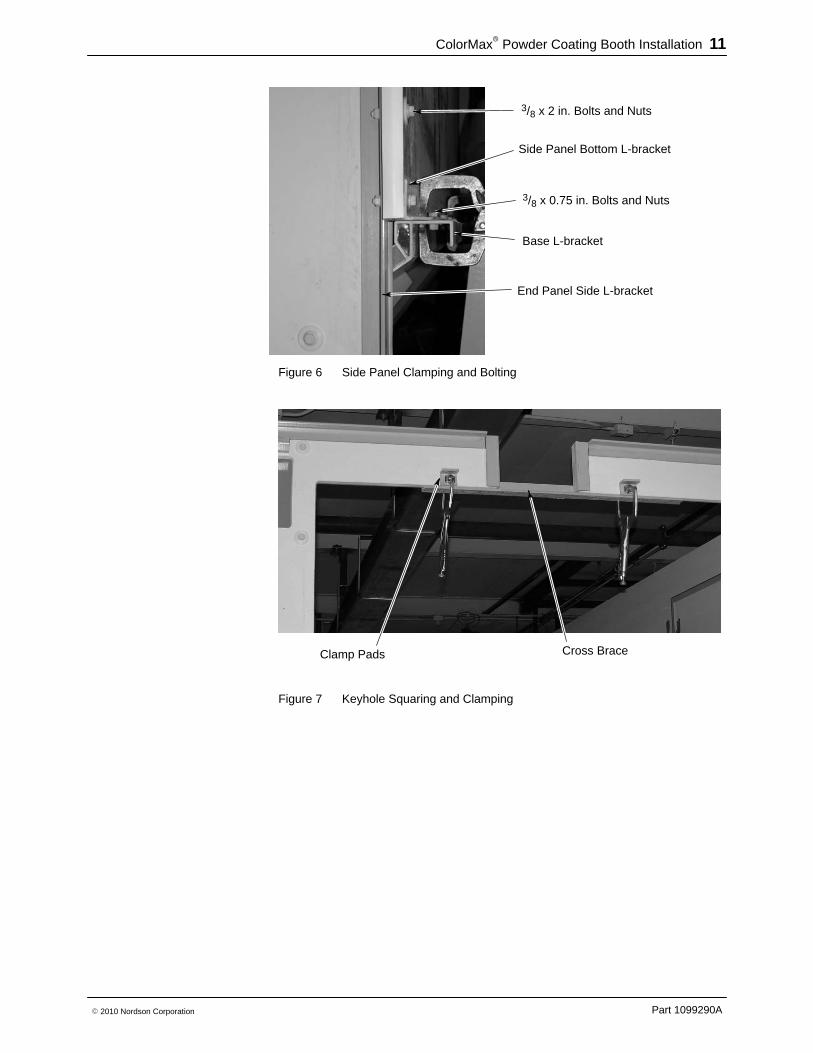
3/8 x 0.75 in. Bolts and Nuts
Base L-bracket
End Panel Side L-bracket
Side Panel Bottom L-bracket
3/8 x 2 in. Bolts and Nuts
Figure 6 Side Panel Clamping and Bolting
Cross BraceClamp Pads
Figure 7 Keyhole Squaring and Clamping
ColorMax� Powder Coating Booth Installation12
Part 1099290A � 2010 Nordson Corporation
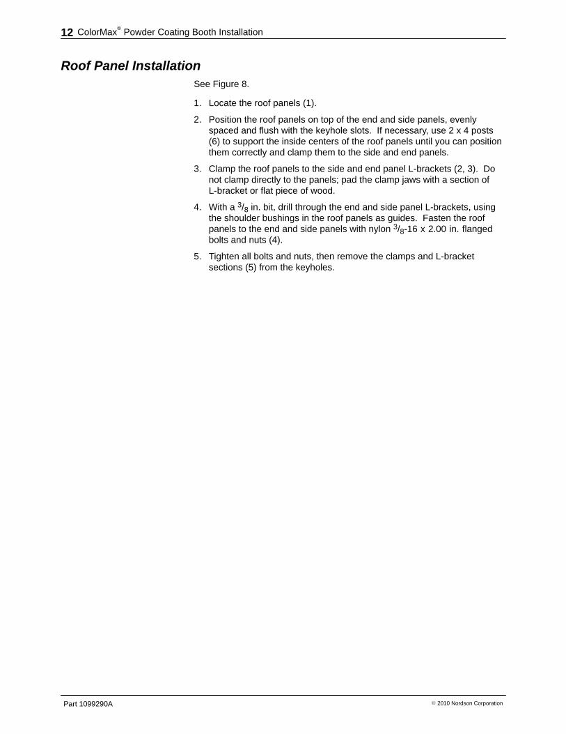
Roof Panel Installation See Figure 8.
1. Locate the roof panels (1).
2. Position the roof panels on top of the end and side panels, evenlyspaced and flush with the keyhole slots. If necessary, use 2 x 4 posts(6) to support the inside centers of the roof panels until you can positionthem correctly and clamp them to the side and end panels.
3. Clamp the roof panels to the side and end panel L-brackets (2, 3). Donot clamp directly to the panels; pad the clamp jaws with a section ofL-bracket or flat piece of wood.
4. With a 3/8 in. bit, drill through the end and side panel L-brackets, usingthe shoulder bushings in the roof panels as guides. Fasten the roofpanels to the end and side panels with nylon 3/8-16 x 2.00 in. flangedbolts and nuts (4).
5. Tighten all bolts and nuts, then remove the clamps and L-bracketsections (5) from the keyholes.
ColorMax� Powder Coating Booth Installation 13
Part 1099290A� 2010 Nordson Corporation
1
4
42
3
Flush
5
5
6
Figure 8 Roof Panel Installation (Typical)
1. Roof panels2. Side panel L-brackets
3. End panel L-brackets4. Plastic 3/8 in. x 2 bolts and nuts
5. Keyhole L-bracket sections6. 2 x 4 supports (if needed)
ColorMax� Powder Coating Booth Installation14
Part 1099290A � 2010 Nordson Corporation
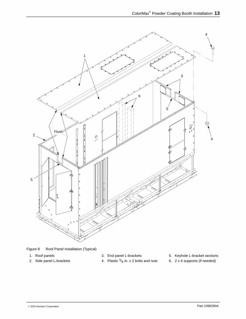
Service Door Installation See Figure 9.
1. Locate the door, hinges, spacers, and latch assembly.
2. Attach the latch assembly to the door with a nylon 3/8-16 x 2.00 in.flanged bolt.
3. Attach the hinges to the door with nylon 3/8-16 x 0.75 flanged bolts.
4. Attach the door to the end panel with spacers and nylon 3/8-16 x 0.75flanged bolts.
3
2
1
54
6
Figure 9 Service Door Installation (Typical)
1. Service door2. Latch assembly
3. Nylon 3/8 x 2 in. bolt4. Spacers
5. Hinges6. Nylon 3/8 x 0.75 bolts
ColorMax� Powder Coating Booth Installation 15
Part 1099290A� 2010 Nordson Corporation
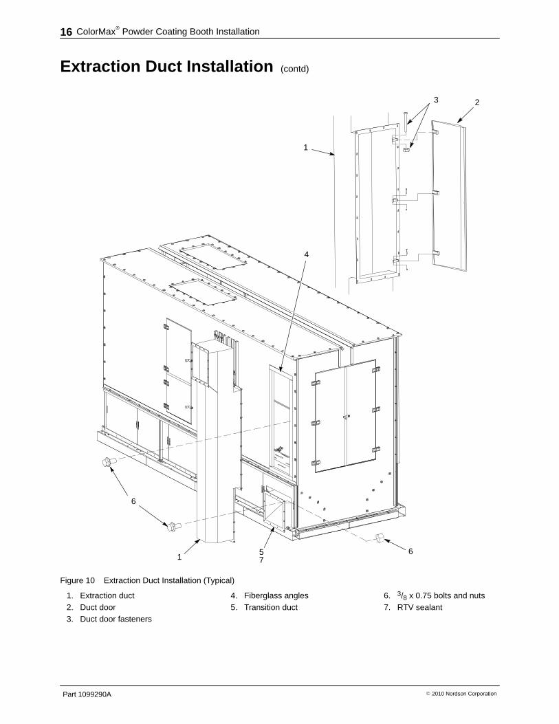
Extraction Duct Installation See Figure 10.
1. Square the inside edges of the transition duct (5) to the side panelextraction duct opening and the stainless steel floor. Bolt the transitionduct into place on the base.
2. Remove the door (2) from the extraction duct (1).
3. Attach the extraction duct to the transition duct, using the two studs onthe transition duct.
4. Position the door hinge brackets on the transition duct flush inside thepanel opening. Make sure to keep the alignment of the extraction ductand panel opening uniform and the edges flush to avoid any buildup ofpowder.
5. Bolt the extraction duct to the transition duct at the four corners of thetransition duct.
6. Transpose the hole pattern in the extraction duct flange to the grayfiberglass angles (4) around the panel opening.
7. Remove the extraction duct.
8. Drill 5/16 in. holes in the gray fiberglass angles. DO NOT drill throughthe inside wall of the panel.
9. Thread the holes with a 3/8-16 tap.
10. Apply a bead of RTV sealant around the transition duct flange.
11. Re-install the extraction duct and secure it to the transition duct withsteel 3/8-16 x 0.75 in. bolts and nuts (6).
12. Re-install the extraction duct door on the inside of the booth.
ColorMax� Powder Coating Booth Installation16
Part 1099290A � 2010 Nordson Corporation
Extraction Duct Installation (contd)
3 2
1
4
51
6
6
7
Figure 10 Extraction Duct Installation (Typical)
1. Extraction duct2. Duct door3. Duct door fasteners
4. Fiberglass angles5. Transition duct
6. 3/8 x 0.75 bolts and nuts7. RTV sealant
ColorMax� Powder Coating Booth Installation 17
Part 1099290A� 2010 Nordson Corporation
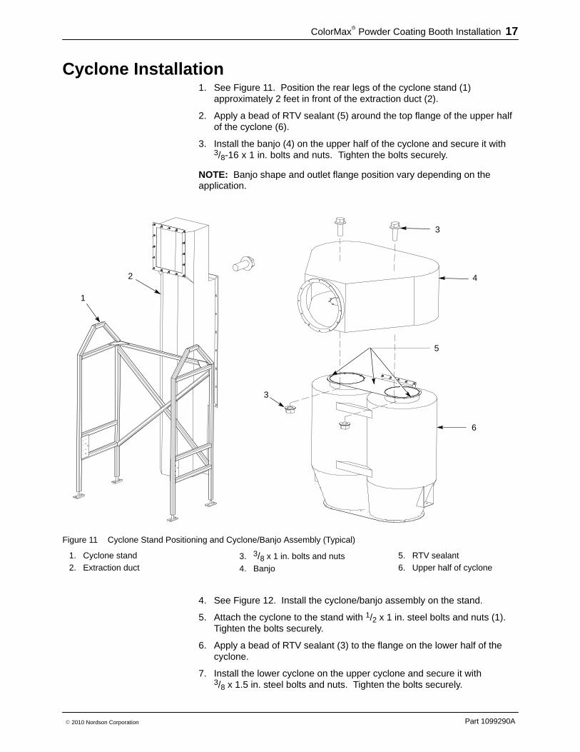
Cyclone Installation 1. See Figure 11. Position the rear legs of the cyclone stand (1)
approximately 2 feet in front of the extraction duct (2).
2. Apply a bead of RTV sealant (5) around the top flange of the upper halfof the cyclone (6).
3. Install the banjo (4) on the upper half of the cyclone and secure it with3/8-16 x 1 in. bolts and nuts. Tighten the bolts securely.
NOTE: Banjo shape and outlet flange position vary depending on theapplication.
1
2
3
3
4
5
6
Figure 11 Cyclone Stand Positioning and Cyclone/Banjo Assembly (Typical)
1. Cyclone stand2. Extraction duct
3. 3/8 x 1 in. bolts and nuts
4. Banjo
5. RTV sealant6. Upper half of cyclone
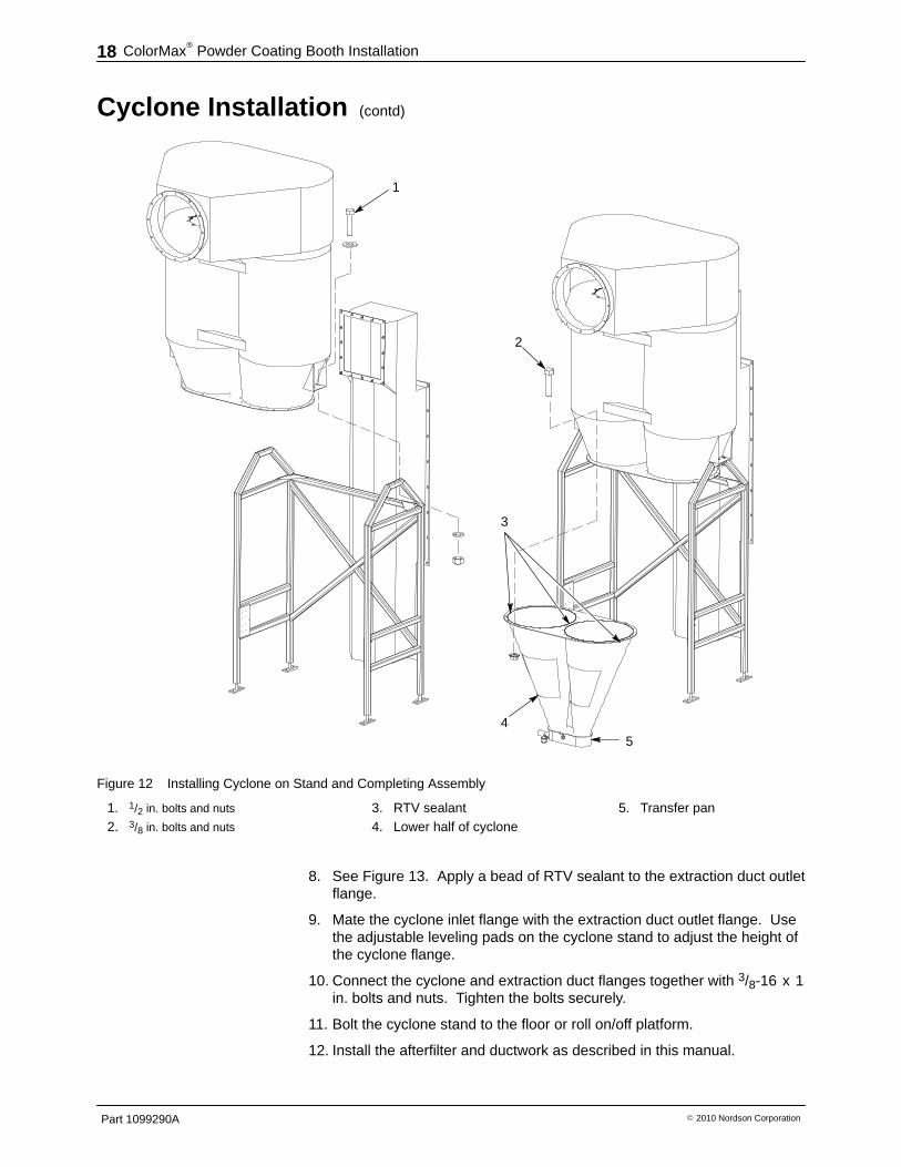
4. See Figure 12. Install the cyclone/banjo assembly on the stand.
5. Attach the cyclone to the stand with 1/2 x 1 in. steel bolts and nuts (1).Tighten the bolts securely.
6. Apply a bead of RTV sealant (3) to the flange on the lower half of thecyclone.
7. Install the lower cyclone on the upper cyclone and secure it with3/8 x 1.5 in. steel bolts and nuts. Tighten the bolts securely.
ColorMax� Powder Coating Booth Installation18
Part 1099290A � 2010 Nordson Corporation
Cyclone Installation (contd)
1
2
3
45
Figure 12 Installing Cyclone on Stand and Completing Assembly
1. 1/2 in. bolts and nuts
2. 3/8 in. bolts and nuts
3. RTV sealant4. Lower half of cyclone
5. Transfer pan
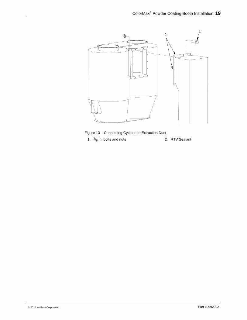
8. See Figure 13. Apply a bead of RTV sealant to the extraction duct outletflange.
9. Mate the cyclone inlet flange with the extraction duct outlet flange. Usethe adjustable leveling pads on the cyclone stand to adjust the height ofthe cyclone flange.
10. Connect the cyclone and extraction duct flanges together with 3/8-16 x 1in. bolts and nuts. Tighten the bolts securely.
11. Bolt the cyclone stand to the floor or roll on/off platform.
12. Install the afterfilter and ductwork as described in this manual.
ColorMax� Powder Coating Booth Installation 19
Part 1099290A� 2010 Nordson Corporation
12
Figure 13 Connecting Cyclone to Extraction Duct
1. 3/8 in. bolts and nuts 2. RTV Sealant
ColorMax� Powder Coating Booth Installation20
Part 1099290A � 2010 Nordson Corporation
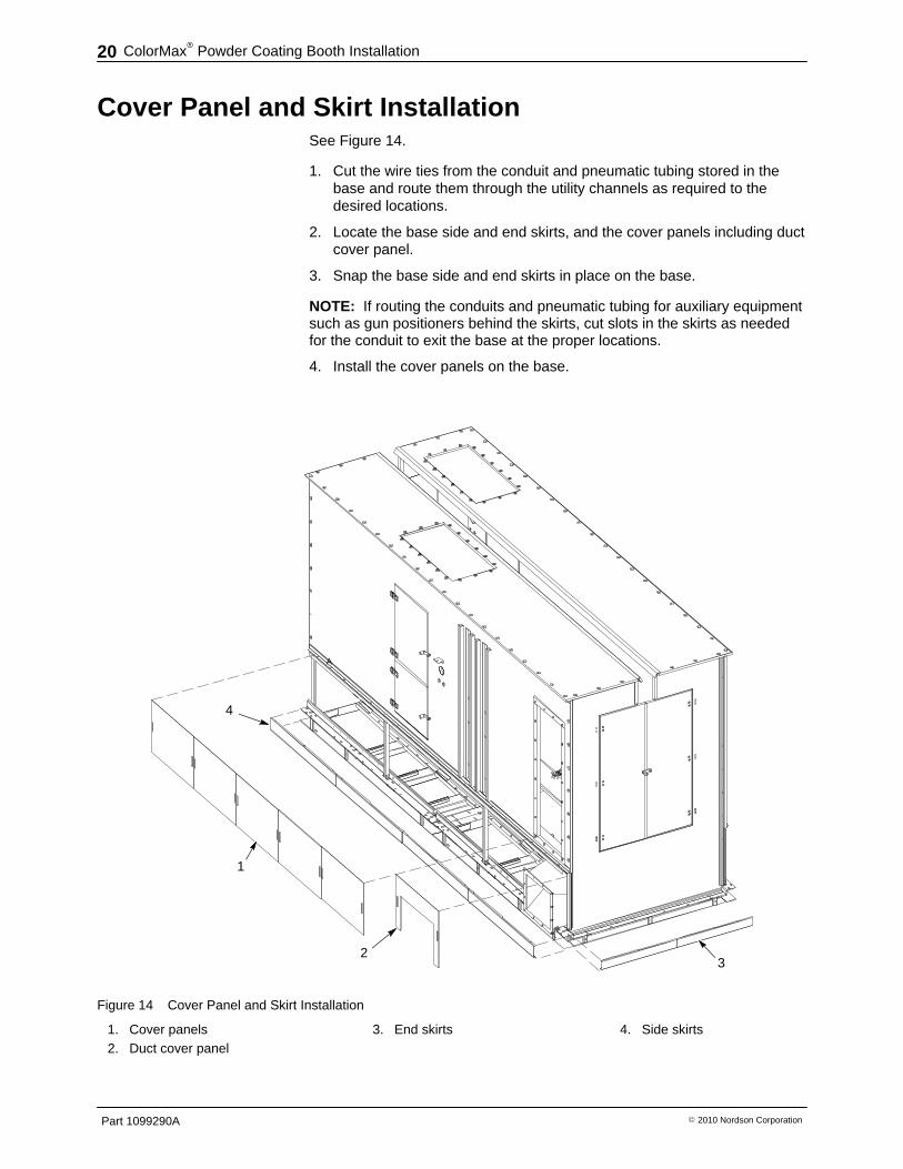
Cover Panel and Skirt Installation See Figure 14.
1. Cut the wire ties from the conduit and pneumatic tubing stored in thebase and route them through the utility channels as required to thedesired locations.
2. Locate the base side and end skirts, and the cover panels including ductcover panel.
3. Snap the base side and end skirts in place on the base.
NOTE: If routing the conduits and pneumatic tubing for auxiliary equipmentsuch as gun positioners behind the skirts, cut slots in the skirts as neededfor the conduit to exit the base at the proper locations.
4. Install the cover panels on the base.
A
1
4
23
Figure 14 Cover Panel and Skirt Installation
1. Cover panels2. Duct cover panel
3. End skirts 4. Side skirts
ColorMax� Powder Coating Booth Installation 21
Part 1099290A� 2010 Nordson Corporation
Booth Seam Sealing NOTE: This procedure should only be done under the direction of aNordson representative.
1. Clean and vacuum the inside corners and seams of the Apogee panelsand stainless steel floor. Leave the plastic film on the stainless steel toprotect it while sealing the seams.
2. Apply blue tape to both sides of all vertical, horizontal, and floor seams,maintaining a 1/8 inch gap on either side of the seam.
3. Apply two-component Pro-Set sealer to all seams, making sure none ofthe sealer gets on the Apogee panel or stainless steel surfaces.
4. Remove excess sealer from the seams before it sets up.
5. Remove the blue tape from the seams after the sealer sets up.
6. Let the sealer stand for 24 hours before preparing the booth forproduction.
AeroDeck� Installation 1. Install the bumper stops, if not already installed, into the pre-drilled holes
in the base panels and secure them with 3/8-16 x 0.75 nylon screws andwashers.
2. Place temporary stands, the same height as the stops, on the flooropposite the pin supports.
3. Locate the forward AeroDeck panel 1/2 inch from the end panel and anequal distance from side to side. Make sure the air fittings on theunderside of the AeroDeck panel are away from the end panel.
4. Fold open the hinges and mark the hinge hole patterns on the AeroDeckpanels.
5. Drill holes in the AeroDeck panels with a 5/16 in. drill bit, and thread witha 3/8-16 tap.
6. Secure the hinges to the AeroDeck panels with 3/8-16 x 2 in. flat-headplastic screws and jam nuts. Cut off any excess threads flush with thejam nuts.
7. Make sure the AeroDeck panels pivot smoothly on the hinges and areplumb with the floors.
ColorMax� Powder Coating Booth Installation22
Part 1099290A � 2010 Nordson Corporation
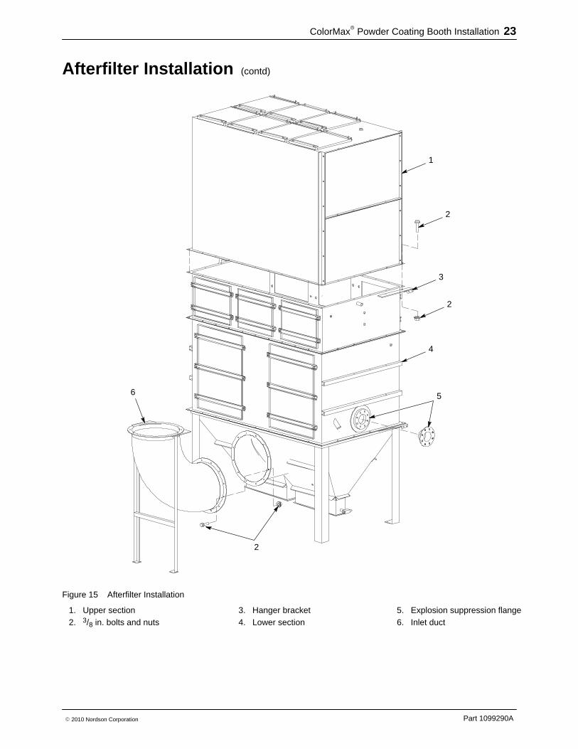
Afterfilter Installation See Figure 15.
1. Locate the upper and lower afterfilter sections (1, 4).
2. Consult your layout drawings to determine the location of the afterfilter.Mark location on floor.
3. Move the lower section into place.
4. Lift the upper section onto the lower section. Line up the bolt holes andfasten the two sections together with 3/8-16 x 1 in. bolts and nuts (2).
5. Attach the hanger bracket (3) to the afterfilter with two of the bolts andnuts used to secure the upper and lower sections.
6. Attach the inlet duct (6) to the lower section with 3/8-16 x 1 in. bolts andnuts.
7. Install the explosion suppression containers (5) and system controls(customer supplied) according to the layout drawings andmanufacturer’s instructions.
ColorMax� Powder Coating Booth Installation 23
Part 1099290A� 2010 Nordson Corporation
Afterfilter Installation (contd)
1
2
3
2
4
5
2
6
Figure 15 Afterfilter Installation
1. Upper section2. 3/8 in. bolts and nuts
3. Hanger bracket4. Lower section
5. Explosion suppression flange6. Inlet duct
ColorMax� Powder Coating Booth Installation24
Part 1099290A � 2010 Nordson Corporation
Duct Installation
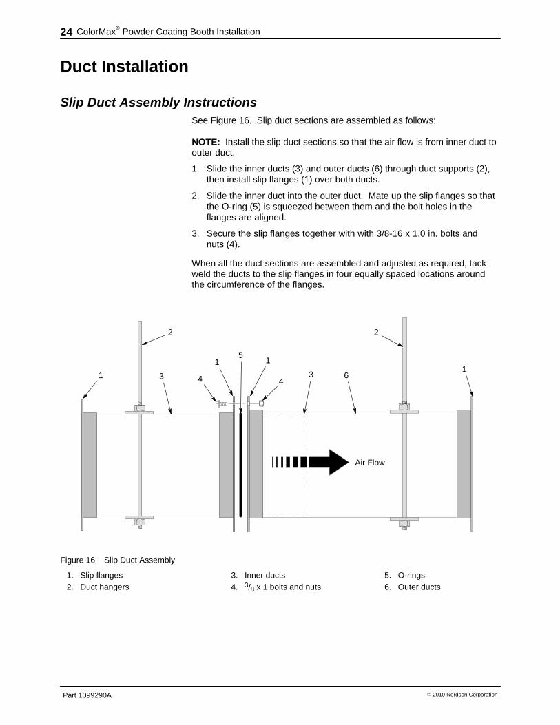
Slip Duct Assembly Instructions See Figure 16. Slip duct sections are assembled as follows:
NOTE: Install the slip duct sections so that the air flow is from inner duct toouter duct.
1. Slide the inner ducts (3) and outer ducts (6) through duct supports (2),then install slip flanges (1) over both ducts.
2. Slide the inner duct into the outer duct. Mate up the slip flanges so thatthe O-ring (5) is squeezed between them and the bolt holes in theflanges are aligned.
3. Secure the slip flanges together with with 3/8-16 x 1.0 in. bolts andnuts (4).
When all the duct sections are assembled and adjusted as required, tackweld the ducts to the slip flanges in four equally spaced locations aroundthe circumference of the flanges.
2
1 4 4
511
3 61
2
Air Flow
3
Figure 16 Slip Duct Assembly
1. Slip flanges2. Duct hangers
3. Inner ducts4. 3/8 x 1 bolts and nuts
5. O-rings6. Outer ducts
ColorMax� Powder Coating Booth Installation 25
Part 1099290A� 2010 Nordson Corporation
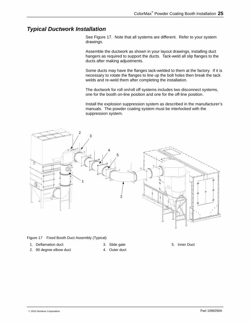
Typical Ductwork Installation See Figure 17. Note that all systems are different. Refer to your systemdrawings.
Assemble the ductwork as shown in your layout drawings, installing ducthangers as required to support the ducts. Tack-weld all slip flanges to theducts after making adjustments.
Some ducts may have the flanges tack-welded to them at the factory. If it isnecessary to rotate the flanges to line up the bolt holes then break the tackwelds and re-weld them after completing the installation.
The ductwork for roll on/roll off systems includes two disconnect systems,one for the booth on-line position and one for the off-line position.
Install the explosion suppression system as described in the manufacturer’smanuals. The powder coating system must be interlocked with thesuppression system.
32
2
45
1
Figure 17 Fixed Booth Duct Assembly (Typical)
1. Deflamation duct2. 90 degree elbow duct
3. Slide gate4. Outer duct
5. Inner Duct
ColorMax� Powder Coating Booth Installation26
Part 1099290A � 2010 Nordson Corporation
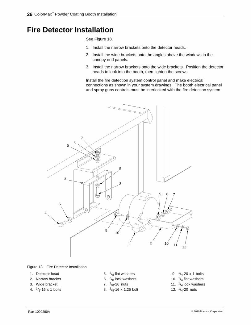
Fire Detector Installation See Figure 18.
1. Install the narrow brackets onto the detector heads.
2. Install the wide brackets onto the angles above the windows in thecanopy end panels.
3. Install the narrow brackets onto the wide brackets. Position the detectorheads to look into the booth, then tighten the screws.
Install the fire detection system control panel and make electricalconnections as shown in your system drawings. The booth electrical paneland spray guns controls must be interlocked with the fire detection system.
76
5
3
4
5
5
8
910
2 10 11 12
5 6 7
1
Figure 18 Fire Detector Installation
1. Detector head2. Narrow bracket3. Wide bracket4. 3/8-16 x 1 bolts
5. 3/8 flat washers6. 3/8 lock washers7. 3/8-16 nuts8. 3/8-16 x 1.25 bolt
9. 1/4-20 x 1 bolts10. 1/4 flat washers11. 1/4 lock washers12. 1/4-20 nuts
ColorMax� Powder Coating Booth Installation 27
Part 1099290A� 2010 Nordson Corporation
Booth Conditioning Required: Acetone or 80% Isopropyl Alcohol, water, 5 gallon bucket,detergent, pre-washed 100% cotton rags.
NOTE: If the booth surfaces are not conditioned, residues frommanufacturing and installation may interfere with booth blowoff and cleaningand cause powder contamination.
1. Wipe down the entire canopy with acetone or 80% isopropyl alcohol andspecified rags.
2. Wash all surfaces with soapy water and specified rags. A continuouswet surface is not necessary; it does not matter if surfaces air-dry beforethe next step.
3. Rinse all surfaces TWICE with clean water and specified rags. Allow toair-dry.
NOTE: From this point on, do not touch the interior surfaces with barehands. Operators should wear cotton gloves. If you have difficulty blowingpowder off booth surfaces, reconditioning may be required. To reconditionthe booth, perform steps 2 and 3.
Completing the Installation Position the feed center, manual operator platforms, photoeye/scannerstand, fixed gun stands or gun positioners as shown on your system layoutdrawings. Do not bolt the fixed gun stands and gun positioners to the flooruntil the automatic spray guns are mounted and aligned with the gun slots.
Install pneumatic and electrical drops as shown on your system drawings.
Install the electrical panels, control panels, and junction boxes as shown onthe drawings.
Make the pneumatic and electrical connections shown on the drawings. Allwiring must be done by a qualified electrician according to code.
Your Nordson installer and field engineers will help you complete the rest ofthe system installation and startup the system.
ColorMax� Powder Coating Booth Installation28
Part 1099290A � 2010 Nordson Corporation
ColorMax Powder Coating System Installation 29
Part 1099290A� 2010 Nordson Corporation
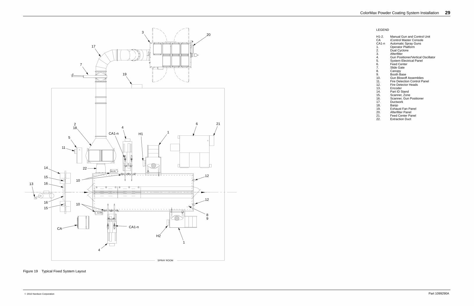
LEGEND
H1-2. Manual Gun and Control UnitCA iControl Master ConsoleCA1-n Automatic Spray Guns1. Operator Platform2. Dual Cyclone3. Afterfilter4. Gun Positioner/Vertical Oscillator5. System Electrical Panel6. Feed Center7. Slide Gate8. Canopy9. Booth Base10. Gun Blowoff Assemblies11. Fire Detection Control Panel12. Fire Detector Heads13. Encoder14. Part ID Stand15. Scanner, Zone16. Scanner, Gun Positioner17. Ductwork18. Banjo19. Exhaust Fan Panel20. Afterfilter Panel21. Feed Center Panel22. Extraction Duct
20
19
7
17
3
1
6 21218
5
11
14 22
13
15
16
16
15
CA CA1-n
1
H2
H1
4
4
CA1-n
889
12
12
10
10
SPRAY ROOM
Figure 19 Typical Fixed System Layout
ColorMax Powder Coating System Installation 30
Part 1099290A� 2010 Nordson Corporation
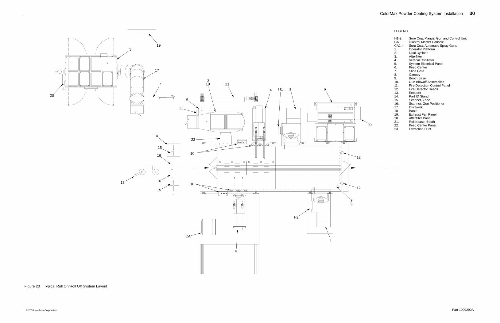
LEGEND
H1-2. Sure Coat Manual Gun and Control UnitCA iControl Master ConsoleCA1-n Sure Coat Automatic Spray Guns1. Operator Platform2. Dual Cyclone3. Afterfilter4. Vertical Oscillator5. System Electrical Panel6. Feed Center7. Slide Gate8. Canopy9. Booth Base10. Gun Blowoff Assemblies11. Fire Detection Control Panel12. Fire Detector Heads13. Encoder14. Part ID Stand15. Scanner, Zone16. Scanner, Gun Positioner17. Ductwork18. Banjo19. Exhaust Fan Panel20. Afterfilter Panel21. Rollerbase, Booth22. Feed Center Panel23. Extraction Duct
20
319
17
7 18 21
4 H1 1
1
H2
12
12
22
6
4
CA
10
23
89
15
16
15
16
14
13
2
5
11
10
Figure 20 Typical Roll On/Roll Off System Layout
ColorMax Powder Coating System Installation 31
Part 1099290A� 2010 Nordson Corporation
AC InPower Supply
iControl PC
CAN
120 Vac
120 Vac
Terminals for
Zone InputPart ID Inputs
iControl Enclosure
Gun Control Cards
IsolatedInput Interface
AC In
CANPC104
I/OPC104
EthernetPCI
16
Gun Cables
Network Interface PanelPN 1057333
Ethernet Switch
25-Conductor Input Cable
Ethernet
Ethernet
Ethernet
Ethernet
Ethernet
Remote Part ID / Photoeye / Scanner Stand
Ethernet
25-Conductor Input Cable
AC J-Box (J-5)AC In
AC Out
120 Vac Power Supply
FieldBusCoupler
Analog
AC Out
Run in onecommon conduit
Zone InputsPart ID Inputs
Run in onecommon conduit To Booth #2
30 Watt Photoeye
PN 103589724 Vdc
AC Adapter
AC Adapter
Eth
erne
t Sw
itch
120
Vac
100 Meter Length Limit
100
Met
er L
engt
h Li
mit
In/Out Positioner
PN 1055890
RIBBON
Encoder Input
ToSlaveConsoleCAN AUX
CAN
Encoder Inputs
25-C
ondu
ctor
Inpu
t Cab
leE
ther
net
Booth Control PanelCAN IN CAN OUT
(Optional)
Ethernet Field Connection
CAN
iFlow Modules
Scanner J-Box
Controller
In/Out Positioner PanelPN 1055889 orPN 1055883 (retrofit) orPN 1070103 (reciprocator)
Control Panel
Power Supply
FieldBus Controller
Reciprocator SpeedController
3 Phase In
Control Panel
Power Supply
FieldBus Controller
Reciprocator SpeedController3 Phase In
J-Box
Terminals:
Scanner
Ethernet
CAN
Power
Powder Booth
NOTE: Your system may not have allthe options shown here.
NOTE:AC Adapter, EthernetSwitch, and dashed linewiring are Booth #2Optional Components.
Positioner Control PanelPN 1055889 (In/Out)PN 1058883 (In/Out Retrofit)PN 1070103 (In/Out+Reciprocator)
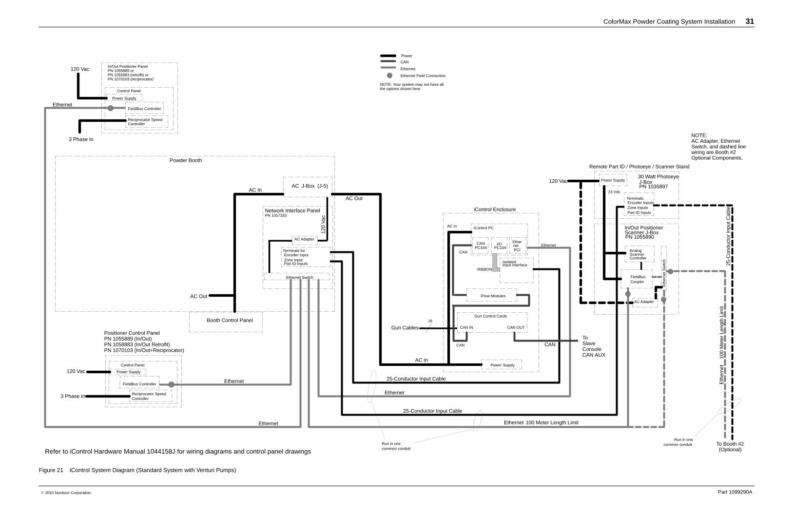
Refer to iControl Hardware Manual 1044158J for wiring diagrams and control panel drawings
Figure 21 iControl System Diagram (Standard System with Venturi Pumps)
ColorMax Powder Coating System Installation 32
Part 1099290A� 2010 Nordson Corporation
AC In (S) Power Supply
iControl
CAN
CA
N In
In/Out Positioner PanelPN 1055889 orPN 1070103 (reciprocator)
AC In (U)
AC In (U)
Booth I/O
Terminals:
Vert. Zone InputPart ID Inputs
iControl Enclosure
Gun 1-16 KV Cards
Gun 17-32 KV Cards
IsolatedInput Interface
AC In (U)
CAN
CAN,PC104
I/O,PC104
Ethernet,PCI
Powder Booth
Gun Cables
Network Interface PanelPN 1057333
CAN Out
CAN In
Ethernet Switch
Parallel Inputs (25 conductor)
Ethernet
Ethernet
Ethernet
Ethernet
Eth
erne
t
Ethernet
Remote Part ID / Photoeye Stand
Ethernet
AC J-Box (J-5)
AC Out(S&U)
AC In (S&U)
AC Out
AC In (U)
Power Supply
Control Panel
Power Supply
AC Out (S&U)
Run in onecommon conduit
Terminals
Vert. Zone InputPart ID Inputs
Run in onecommon conduit Ethernet and Discete Part
ID to Booth #2
30 WATT PEJB,PN 1035897
24 VDC
AC Adapter
AC Adapter
Eth
erne
t Sw
itch
Note:AC Adapter, Ethernetswitch, and dashed linewiring are 2nd Boothoptional components.
AC Out (U)
100 meter length Limit
100
met
er le
ngth
Lim
it
Booth Control Panel
GUNMOVER SCANNERBOX, PN 1053590
RIBBON
Denotes: Ethernet Field Connection
FieldBus Coupler
Parallel Inputs (25 conductor)
FieldBus Controller
PS
Pump Cab 3
PS
Pump Cab 4
FC Solenoid Panel
FC Control Panel
Power Supply
PS
Pump Cab 1
PS
Pump Cab 2
AC In(S&U)
FC Network
Prodigy Powder PortFeed Center
FD Boxpn 307445
AC In (U)
Interlock
3PH In (supply)
CAN In
FC Network JBOXDetails
PumpCab 1
PumpCab 2
PumpCab 4
PumpCab 3
CAN LoopTermination
19 F
t Sea
ltite
le
ngth
max
.
DC Discrete from FC
AC
(U
)
AC (S)
AC (S) AC (S)
AC (S)
DC Discrete to/from GM1
DC Discrete to Booth Control Panel
DC Discrete to/from FC
24 VDC
CAN
J-Box
CAN
CAN In
CAN Out
Power Supply
24 VDC
One common Cable6 meter limit
Run in onecommon conduit
Manual GunPN 1057458
AC Out (S)
Denotes: CAN Field Connection
Reciprocator SpeedController
3ph In
In/Out Positioner PanelPN 1055889 orPN 1070103 (reciprocator)
Control Panel
Power Supply
FieldBus Controller
Reciprocator SpeedController3ph In
3ph Out
AC Discrete fromBooth Control Panel
SolenoidAssemblyDiscrete
AC Discrete to/from FC
If Part ID services two iControlsystems, then AC power must beseparately supplied.
Eth
erne
t
Par
alle
l Inp
uts
(25
cond
ucto
r)
CAN Network Detail
Encoder Inputs;
Power
Ethernet Network
Parallel Inputs (Discrete)CAN Network
J-Box
Encoder Input
AnalogScannerController
Manual GunController 2
Manual GunController 1
NOTE: You system may not have alloptions shown here.
PN1070702
PN 1070693
PN1070692
PN1070694
PN1070780
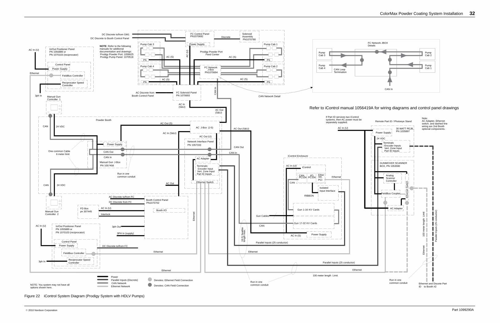
NOTE: Refer to the followingmanuals for additionaldocumentation and drawings:Prodigy Powder Port: 1056625Prodigy Pump Panel: 1070518
Refer to iControl manual 1056419A for wiring diagrams and control panel drawings
Figure 22 iControl System Diagram (Prodigy System with HDLV Pumps)
ColorMax Powder Coating System Installation 33
Part 1099290A� 2010 Nordson Corporation
22
11
ONONOFFOFF
NordsonNordson RR
0055 25253030101020201515
6060404010010090908080707030302020101000
5050++PSIPSI
++PSIPSI
PSIPSI00 3030101055 20202525++1515
10010000101020203030++PSIPSI707080809090505040406060
PSIPSI00 3030101055 20202525++1515
R Q
M
E
C
NP
A
B
L
L
P
F
P
M
L
H4
R
Q
H
K
J K
H
K
J
G
H4
H2
H5
Q
R
M
N
T
AB
CE
A
B
G
GH
J
D
K
F
SMP
V4
V3
V1
V2
V3
10 mm COLLECTOR PULSE
6 mm SURE-MAX PULSE
8 mm SURE-MAXPULSE SOLENOID
6 mm FINAL FILTER
6mm SURE-MAX PUMP
6mm DISCHARGE CLOSE6mm DISCHARGE OPEN
10 mm HOPPER FLUIDIZING
10 mm COLLECTOR TRANSFER
10 mm COLLECTOR FLUIDIZING
10 mm LANCE FLUIDIZING
6 mm VIRGIN PINCH6 mm RECLAIM PINCH
10 mm LANCE UP10 mm LANCE DOWN
NOTE: VIRGIN PILOT PORT NOTUSED WITH SURE-MAX SYSTEM.SUPPLY AIR FROM
AIR MANIFOLD
SUPPLY AIR TOVACUUM PUMP
BLOW GUN
PUMP INSTALLED ONOPPOSITE SIDE OF
FEED CENTER
GREEN PORT (RED PORT PLUGGED)
CYCLONES
SURE-MAXTRANSFER PAN
55-GALLONSCRAP DRUM
SURE-MAXRECEIVER
FEED CENTERCONTROL PANEL
FEED CENTERCONTROL PANEL
BOTTOM VIEW
FEED CENTERCONTROL PANEL
TOP VIEW
LANCEASSEMBLY
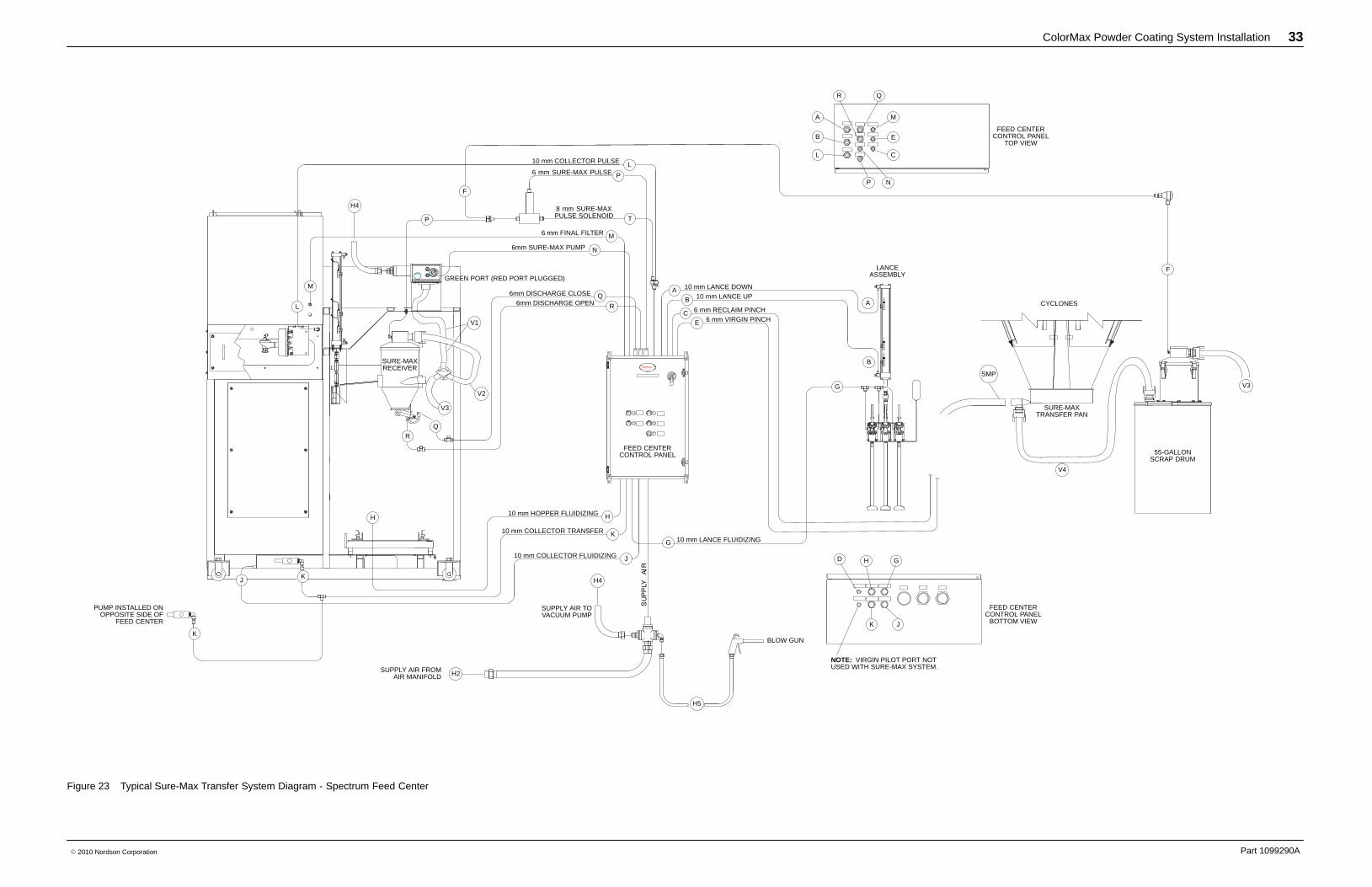
Figure 23 Typical Sure-Max Transfer System Diagram - Spectrum Feed Center
ColorMax Powder Coating System Installation 34
Part 1099290A� 2010 Nordson Corporation
VIRGIN BULK FEED (OPTIONAL)
TWIN CYCLONE
TRANSFER PAN
RECLAIM RECEIVER
PNEUM. PANELON HDLV RECLAIMPUMP MOUNT PLATE
SIEVEFEED CENTER
CONTROL PANEL
16mm
(MAX. 3.5M [12’-0”]
16mm
6mm
16m
m
(MA
X.
3.5M
[12
’-0”]
16mm
16mm
8mm
8mm
6mm
8mm
12m
m
6mm
BASE SUPPLY
AIR MANIFOLD
8mm8mm
6mm
6mm8mm
3/4” PIPE
2 x
10m
m2 x
10m
m
12m
m
P
QE
R
N
PIC
K-U
P T
UB
E
VIRGIN POWDER SOURCE(BOX, DRUM)
15+2520510300PSI
604050908070PSI+3020100100
15+2520510300PSI
PSI+
PSI+500102030708090100
4060
152010302550
PUMP INSTALLED ON OPPOSITESIDE OF FLUID BED SECTION.
K
J
10mm10mm10mm10mm
H
L
M
H2
B
AG
L
M
6mm VIRGIN PILOT
DESCRIPTION
10mm10mm
BA
TUBING SIZE
DEF
10mm10mm
G
IH
C
ITEM
10mm10mm
K
ML
6mm
6mm
N
P 6mm
6mm6mm
R
6mm
Q
J 10mm
HDLV RECLAIM
LANCE FLUIDIZE
LANCE UPLANCE DOWN
FINAL FILTER PRESSURE GAUGECOLLECTOR FILTER PULSE PRESSURECOLLECTOR TRANSFER PUMP
HDLV VIRGIN PUMP PURGE
HDLV TRANSFER PAN FLUIDIZING
PNEUMATIC TUBING CHART
HDLV VIRGIN PUMP
FEED HOPPER FLUIDIZE
COLLECTOR FLUIDIZE
HDLV RECLAIM PUMP PURGE
10mm10mm
10mm6mm
10mm
REF.: TOP VIEW OF CONTROL PANEL REF.: BOTTOM VIEW OF CONTROL PANEL
H G
JKD
R Q
A
B
L
E
M
NP
C
KH
KG
J
N
R
B
A
P
S
E
Q
G
E
Q
BLOW GUN
SUPPLY AIRFROM AIR MANIFOLD
BASE SUPPLY
AIR MANIFOLD
12m
m
6mmS HDLV RECLAIM PUMP MANUAL PURGE
O
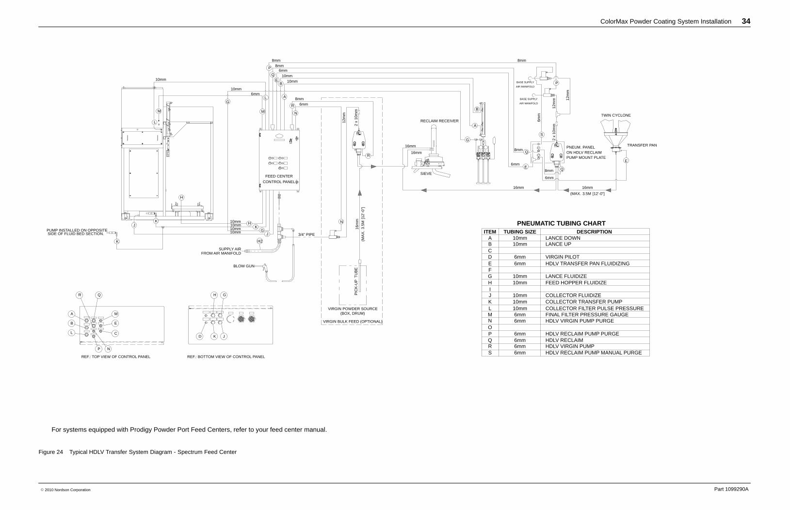
For systems equipped with Prodigy Powder Port Feed Centers, refer to your feed center manual.
Figure 24 Typical HDLV Transfer System Diagram - Spectrum Feed Center