Embed Size (px)
Citation preview
MECHANICAL ENGINEERING
COMBINATION IVU%LEAR POWZR A A D DEQUTING PLANTS
ACKNOWLEDGMENT This article by W . H . Comtois is reprinted from the August 1967 issue of “Mechanical Engineering.”
Tm USE OF NUCLEAR REACTORS as heat sources for processes to desalt sea and brackish water was one of the early applications envisioned for peaceful uses of the atoms in the period following World War 11. It remained, however, to the electric-generating industry and a large government program to de- velop nuclear power into a reliable and economical heat source. The emergence of a large and fast- growing nuclear industry has resulted in renewed hope for economical, large-scale water production as evidenced by several recent studies here and abroad. Concurrently, desalting processes have made great advances with multistage flash evapora- tion appearing as the leading contender for eco- nomical water production.
COMBINATION PLANTS
A combination power and water plant consists of three major systems, viz., a heat source, a power- conversion system, and a water-desalting system. Figure 1 is a schematic dagram of a typical com- bination plant employing a pressurized water reac- tor as its heat source, a conventional steam turbine and generator for electric-power production, and a multistage flash evaporator to produce pure water.
Because of the relatively low temperature re- quirements of distillation plants and the low value of energy at these levels, it has naturally been the trend to combine electric and water-production facilities in one plant.
Company-sponsored studies of nuclear-powered Figure 1. Back-pressure cycle in which the entire exhaust combination electric-generating, waterdesalting ~ ~ w ~ y s ~ ~ . ~ ~ ~ v ~ ~ ~ ~ t ~ $ a ~ ~ FdEz plans have revealed some interesting facets of O P this cycle produces large quantities of electric power. kr-1 timization and economic characteristics. is studying it.
90 NdVdl Enpinears Journdl. Fabrudry 1968
MECHANICAL ENGINEERING NUCLEAR POWER 81 DESALTING PLANTS
In this arrangement, all of the steam exhausted from the turbine is used to heat brine in the water- desalting system. This is commonly referred to as the back-pressure cycle and is the type chosen for study in Israel. This cycle has the advantage of pro- ducing the least amount of electricity for a given amount of water. This consideration is important where large amounts of water are desired but large blacks of power cannot be used.
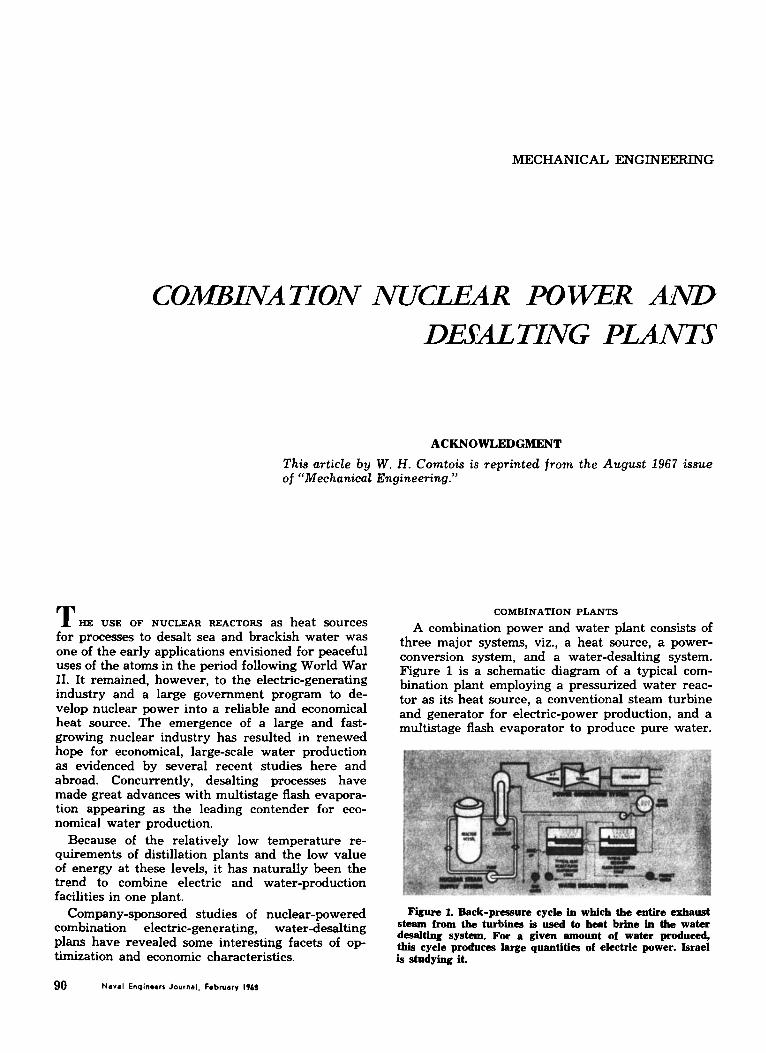
Figure 2 exemplifies the extraction cycle where steam for brine heating is taken at a suitable ex- traction point on the turbine. This cycle is under consideration in the United Arab Republic and is in use in a small fossil-fired plant in St. Thomas, Virgin Islands. This cycle generally has a high product ratio (ratio of power to water) and has usually been used where small amounts of water are required. It is possible, of coure, to produce rather large amounts of water with this arrange- ment. Figure 3 is an example of the multishaft cycle. This arrangement is basically the same as the back-pressure cycle of Figure 1 with a standard condensing turbine operated in parallel with the noncondensing turbine. The water-production capa- bility is the same as the back-pressure cycle, but very large amounts of power also can be generated. This is the type of cycle studied for the Metropolitan Water District in southern California. Both the multishaft and extraction cycles offer greater flexi- bility in operation since the electrical output can be varied over a significant range without affecting operation of the desalting system. The latter can be completely shut down and electric production con- tinued. This is not true for the back-pressure cycle.
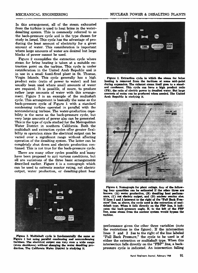
There are many other cycles possible anddmany have been proposed to suit various conditions, but all are variations of the three basic arrangements described earlier. Figure 4 is a nomograph which can be used to estimate reactor rating, net electric output, water production, or desalting-plant heat
Figure 3. Mdtishaft cycle is fundamentally the same aa Figure 1 but usiug parallel eondensing and nonmndeasii turbines. The eleeMcal output am vary over a wide range (even shutdown) without chmging the watsr desalting pro- duction. The California Water District is studying it.
Figure 2. Extraction cycle in which the steam for brine heating is removed from the turbines at some mid-point during expansion. The exhaust steam itself goee to a stand- ard condensor. This cycle can have a high product ratio (PR), the ratio of electric power to desalted water. But large amounts of water can be produced when needed The United Arab Republic is studying it.
Figure 4. Nomograph for plant ratings. Any of the follow- ing four quantities can be cetimated if the other three are known: (A) water production, (B) d d t i n g heat perform- ance, (C) net electric output, and (D) nudear reactor &a If lines 2 and 3 in-ct to the *t of th “FUU B.dr Rse- sure” line, aa above, the cycle used b the extraction of mnl- tishaft type. When it falls directly on the FBP line, it indi- cates the back-pressure angle If, to the left of the FBP line, some steam from the nuclear ~ y ~ t e m wonld b m the turbine.
performance given the other three variables (note the restrictions in the figure). If the intersection lines 2 and 3 liestotherightofthelinelabeled “Full Back Pressure,” the cycle to be used is of either the extrtlction or multishaft type. When thip intersection falls directly on the “FBP” line, a back- pressure cycle is indicated. An intersection falling
N a V d Enpinoars Journal, February 1968 91
NUCLEAR POWER & DESALTING PLANTS MECHANICAL ENGINEERING
to the left of the FBP line indicates that some of the steam to the brine heater is bypassed around the turbine regardless of the cycle used.
COST OF ENERGY
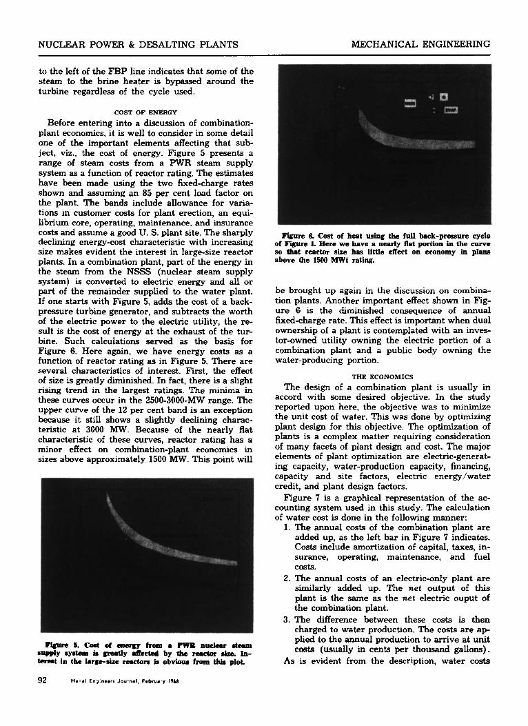
Before entering into a discussion of combination- plant economics, it is well to consider in some detail one of the important elements affecting that sub- ject, viz., the cost of energy. Figure 5 presents a range of steam costs from a PWR steam supply system as a function of reactor rating. The estimates have been made using the two fixed-charge rates shown and assuming an 85 per cent load factor on the plant. The bands include allowance for varia- tions in customer costs for plant erection, an equi- librium core, operating, maintenance, and insurance costs and assume a good IJ. S. plant site. The sharply declining energy-cost characteristic with increasing size makes evident the interest in large-size reactor plants. In a combination plant, part of the energy in the steam from the NSSS (nuclear steam supply system) is converted to electric energy and all or part of the remainder supplied to the water plant. If one starts with Figure 5, adds the cost of a back- pressure turbine generator, and subtracts the worth of the electric power to the electric utility, the re- sult is the cost of energy at the exhaust of the tur- bine. Such calculations served as the basis for Figure 6. Here again, we have energy costs as a function of reactor rating as in Figure 5. There are several characteristics of interest. First, the effect of size is greatly diminished. In fact, there is a slight rising trend in the largest ratings. The minima in these curves occur in the 2500-3000-MW range. The upper curve of the 12 per cent band is an exception because it still shows a slightly declining charac- teristic at 3000 MW. Because of the nearly flat characteristic of these curves, reactor rating has a minor effect on combination-plant economics in sizes above approximately 1500 MW. This point will
Fislve 6. Cost of heat using the full back-pressure cycle of F-e 1. Here we have a nearly flat portion in the curve so that reactor size has little effect on economy in plans above the 1500 MWt rating.
be brought up again in the discussion on combina- tion plants. Another important effect shown in Fig- ure 6 is the diminished consequence of annual hed-charge rate. This effect is important when dual ownershp of a plant is contemplated with an inves- tor-owned utility owning the electric portion of a combination plant and a public body owning the water-producing portion.
THE ECONOMICS
The design of a combination plant is usually in accord with some desired objective. In the study reported upon here, the objective was to minimize the unit cost of water. This was done by optimizing plant design for this objective. The optimization of plants is a complex matter requiring consideration of many facets of plant design and cost. The major elements of plant optimization are electric-generat- ing capacity, water-production capacity, financing, capacity and site factors, electric energy/water credit, and plant design factors.
Figure 7 is a graphical representation of the ac- counting system used in this study. The calculation of water cost is done in the following manner:
1. The annual costs of the combination plant are added up, as the left bar in Figure 7 indicates. Costs include amortization of capital, taxes, in- surance, operating, maintenance, and fuel COSts.
2. The annual costs of an electric-only plant are similarly added up. The net output of this plant is the same as the net electric ouput of the combination plant.
3. The difference between these costs is then charged to water production. The costs are ap- plied to the annual production to arrive at unit costs (usually in cents per thousand gallons).
As is evident from the description, water costs
MECHANICAL ENGINEERING NUCLEAR POWER & DESALTING PLANTS
Fhpre 7. Method of detbnniniag water-production costs. The electric-only plant is the same net output as the net electric output of the combination plant. Water cosb are charged only with incremental expense in nuclear fnel, supply systcaa, &. This, however, in no way penalizes the cost of producing electricity.
are enhanced by being charged only for increments in such things as NSSS costs, fuel, and so on. This, however, in no way penalizes the cost of producing electricity.
The optimization of a combination plant where the effect of so many variables has to be taken into account is done by trial and error. Because of the large number of repetitive calculations involved, we have devised a computer program, which incorpo- rates a pattern search routine, to perform the op- timization. An initial design is performed using in- put estimates of certain parameters and fixed
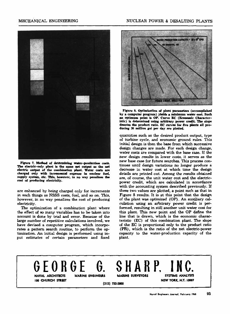
b e 8. optknizatlon of plant pnrametere (accomplished by a computer program) yields a minimum water cost. Such an o p t i m u m point is OP. Curve EC (Economic Character- istic) is detnrmn ' ed using arbitrary power credit. The slope denotes the product ratio. EC curves for flve plrrnts all pro- ducing 30 million gal per day are plotted.
quantities such as the desired product output, type of turbine cycle, and economic ground rules. This initial design is then the base from which successive design changes are made. For each design change, water costs are compared with the base case. If the new design results in lower costs, it serves as the new base case for future searches. This process con- tinues until design variations no longer produce a decrease in water cost at which time the design details are printed out. Among the results obtained are, of course, the unit water cost and the electric- power credit, which are calculated in accordance with the accounting system described previously. If these two values are plotted, a point such as that in Figure 8 results. It is at this point that the design of the plant was optimized (OP). An auxiliary cal- culation using an arbitrary power credit is per- formed, resulting in still another unit water cost for this plant. This new point and the OP define the line that is drawn, which is the economic charac- teristic (EC) of this combination plant. The slope of the EX is proportional only to the product ratio (PR), which is the ratio of the net electric-power capacity to the water-production capacity of the plant.
G E O R G E G . S H A R P , I N C . NAVAL ARCHITECTS MARINE EN61NEERS MARINE SURVETORS SYSTEMS ANALYSTS
(212) 732.2- 100 CHURCH STREET NEW YORK, N.Y. 10007
Naval Enginwrs Journal. February 1968 93
NUCLEAR POWER & DESALTING PLANTS MECHANICAL ENGINEERING
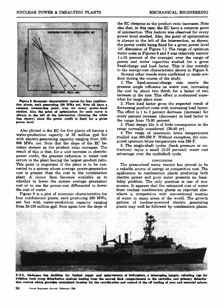
Figwe 9. Eeoaomie eharaeteristie for four eombina- tion plants, each gsoerstinl[ 500 MWe net. Note all have a coamron int-tion point, true for every power-level rtudied. luso the point of optimization for each curve is always to the left of the intcrsection (forming the white lIns shown) since the power credit i s Bxed for a given power level.
Also plotted is the EC for five plants all having a water-production capacity of 30 million gpd but with electric-generating capacity ranging from 100- 800 W e , net. Note that the slope of the EC be- comes steeper as the product ratio increases. The result of this is that, for a unit increase in electric- power credit, the greatest reduction in water cost occurs in the plant having the largest product ratio. This point is important if the plant is to be con- nected to a system whose average power-generation cost is greater than the cost in the combination plant. A choice then becomes available as to whether to lower the system average generation cost or to use the power-cost differential to lower the cost of water.
Figure 9 is a plot of economic characteristics for four combination plants, each producing 500 W e , net but with water-production capacity ranging from 30-150 million gpd. Note again how the slope of
the EC steepens as the product ratio increases. Note as0 that, in this case, the EC have a common point of intersection. This feature was observed for every power level studied. Also, the point of optimization is always to the left of the intersection, as shown, the power credit beiig fixed for a given power level (d. discussion of Figure 7.) The range of optimum water costs in Figures 8 and 9 was relatively narrow (+15 percent of the average) over the range of power and water capacities studied for a given fixed-charge and load factor. This is due entirely to the energy-cost characteristic shown in Figure 6.
Several other trends were confirmed or made evi- dent during the course of the study.
1. The fixed-annual-charge rate exerts the greatest single influence on water cost, increasing the cost by about two thirds for a fador of two increase in the rate. This effect is moderated some- what for large plant sizes.
2. Plant load factor gives the expected result of decreasing product costs with increasing load factor. The effect is 1 to 2 percent decrease (increase) for every percent increase (decrease) in load factor in the range from 75-95 percent.
3. Plant design life is of little consequence in the range normally considered (30-40 yr).
4. The range of maximum brine temperatures studied was 200-250 F. Without exception, the com- puted optimum brine temperature was 250 F.
5. The single-shaft cycles (back pressure or ex- traction) enjoy a small (5-10 percent) water cost advantage over the multishaft cycle.
CONCLUSION The pressurized water reactor has proved to be
a reliable source of energy at competitive cost. The application to combination plants producing both electric power and pure water presents no feasi- bility problem. The only question is one of eco- nomics. It appears that the estimated cost of water from nuclear combination plants as reported else- where is competitive with conventional sources of water in many areas of the world. The growth pattern of nuclear-powered electric generating plants may well be followed by Combination plants.
U.S.S. Dubuqua lus facilities for limited repair and mainteamwe of hlioopbrr, a tasscOping hanger, dueling riga for aviation fads troop debarkation atations leading from tbe second deck compdmentn to the catwalks, and primary debarka- tion control which pmvidca centralized location for the roordlnation and control of the off loading of men and material ashore.
94 Naval Enginoorr Journal. Fabruary IT68