Embed Size (px)
Citation preview
1
Combustion in Microscale Heat-Recirculating Burners
Lars Sitzki, Kevin Borer, Ewald Schuster and Paul D. RonneyDept. Aerospace and Mechanical Engineering
University of Southern California, LA, CA 90089-1453 USA
Steffen WussowInstitute of Fire Department, Saxony - Anhalt
39175 Heyrothsberge, Germany
ABSTRACT
In order to optimize the design of microscale combustors,macroscale spiral counterflow heat-recirculating "Swiss Roll"burners were constructed and tested using hydrocarbon fuels atthe Reynolds and Damk�hler numbers typical of desiredmicroscale values. Both Ò2DÓ Swiss Roll burners (basically alinearly extruded spiral shape) and fully Ò3DÓ Swiss Roll burners(in which the spiral is extruded in a circular pattern to create atoroidal geometry) were built using a ceramic "rapidprototyping" technique. It was found that combustion could besustained in a low-temperature "flameless" mode in which novisible flame occurs. Mixtures well below the conventional leanflammability limit could be burned even at mean flow velocities30 times the stoichiometric laminar burning velocity. Theaddition of catalytic materials in the combustion region wasfound to either increase or decrease the range of flammablemixtures, by substantial amounts in both cases, depending on theReynolds number. The possibility of using fuels that are self-starting (i.e. require no external ignition source) on catalyticsurfaces was also explored. Preliminary numerical simulationscompared rather poorly with the experimental results, most likelydue to inaccurate heat loss and chemical reaction rate (both gas-phase and surface) sub-models. It is concluded that combustionin microscale burners is feasible, however, heat recirculation,catalysis and careful management of heat losses are essential tothe success of such designs.
Keywords: combustion, extinction limits, MEMS
INTRODUCTION
It is well known that the use of combustion processes forelectrical power generation provides enormous advantages overbatteries in terms of energy storage per unit mass and in terms ofpower generation per unit volume, even when the conversionefficiency in the combustion process from thermal energy toelectrical energy is taken into account. For example, hydrocarbonfuels provide an energy storage density of typically 45 MJ/kg,whereas even modern lithium ion batteries commonly used inlaptop computers provide only about 0.50 MJ/kg. Thus, even atonly 10% conversion efficiency from thermal to electricalenergy, hydrocarbon fuels provide 10 times higher energystorage density than batteries. For this reason automotive andaviation vehicles employ internal combustion engines for primemoving and electrical power generation almost entirely to theexclusion of batteries, even in vehicles whose mass may be lessthan 1 kg or more than 105 kg. Still, these advantages ofcombustion processes have not yet been exploited for thegeneration of electrical power in small-scale systems such as
laptop computers, cell phones and Micro Electro-MechanicalSystem (MEMS) devices. The ultimate goal of our current effortsis to develop combustion-driven power generation devices atMEMS-like scales.
Combustion volume
Products
Reactants
1500K 1200K 500K 400K 300K
1500K 1500K 800K 700K 600K
Figure 1. Schematics of excess enthalpy combustors. Upper:generic linear counterflow heat exchanger / combustor withtypical temperatures shown; lower left: linear device rolled upinto a "two dimensional" Swiss Roll combustor; lower: cutawayview of "three-dimensional " toroidal Swiss Roll device.
Most current micro-scale combustion generator conceptsemploy scaled-down versions of existing macroscale devices, inparticular internal combustion engines, though such microdevicesexperience more difficulties with heat losses, friction, sealing,fabrication, assembly etc. than their macroscale counterparts.Because of these limitations, we have focussed our attention on apower source having no moving parts and not requiring high-precision fabrication and assembly. Consequently, we havechosen a heat-recirculating combustor design. Electrical poweris generated by thermoelectric elements embedded in wallsbetween cold incoming reactants and hot outgoing products. Thecomplicated geometry can be monolithically fabricated at micro-scale by using EFAB (Electrochemical FABrication) technology[1]. By this method, one can produce arbitrary 3-D structures bystacking hundreds of individually patterned layers. For brevity,in this paper only the combustion aspects of our project arepresented, which may be applicable to other types of microscaleheat and/or power generation systems. The combustion approachis tested using macroscale prototypes.
The Third Asia-Pacific Conference on CombustionJune 24-27, 2001, Seoul, Korea
2
APPROACH
Weinberg and collaborators [2] have shown that quenchinglimits can be effectively eliminated through the use ofrecirculation of thermal energy from the combustion products topreheat the reactants without recirculating the combustionproducts themselves. Such devices are termed "excess enthalpy"burners because the thermal enthalpy of the incoming reactants isincreased via preheating without diminishing the chemicalenthalpy via chemical reaction, thus at the point within the devicethat combustion does occur, the reactants can have much highertotal enthalpy (chemical plus thermal) than the fresh reactants.Figure 1 (upper) shows a generic schematic of an excess enthalpycombustor. The large external surface area of such a heatexchanger would typically lead to large heat losses to ambient,but by wrapping up the heat exchanger in a ÒSwiss rollÓconfiguration (Fig. 1, middle) such heat losses are effectivelyeliminated and in fact the heat transfer between windingsbecomes an integral part of the burner design. Of course, for sucha burner to work, the rate of heat conduction outward across theturns of the burner must be slower than the rate at which heat isconvected inward. The ratio of convective to conductive transferis proportional to Ud/α , where U is the gas velocity in thechannel, d the channel width and α is the thermal diffusivity ofthe gas. Since for gases α ¯ ν , where ν is the kinematicviscosity, this is equivalent to requiring that the Reynoldsnumber Re ≡ Ud/ν be sufficiently larger than unity.Consequently, as long as Re is sufficiently large, combustion canbe sustained in Swiss-roll type burners in micro-scale deviceseven though combustion could not possibly be sustained indevices of channels with cold walls except at very high pressuresand/or with walls preheated to impracticably high temperatures.Even in a ÒSwiss rollÓ configuration, a planar roll will sufferlarge heat losses in the lateral direction. A mechanism to avoidthis, which was in fact proposed by Lloyd and Weinberg (1975),is to wrap the Swiss roll in the lateral direction as well to create atoroidal shape (Fig. 1, lower). While this is difficult withvirtually all prior MEMS technologies which allow only for thefabrication of quasi-two-dimensional structures, it is possible tobuild such a three-dimensional microstructure using the EFABtechnique to be used in this project.
An additional means to reduce the impact of heat loss inmicroscale systems is through the use of catalytic combustion. Incontrast to gas phase combustion, catalytic combustion occurs ata surface reaction without a flame. Catalytic combustion canserve several useful purposes in this context. Since chemicalreactions only occur on the catalyst surface, the location of theheat source is fixed. This makes heat transfer design simpler thangas-phase combustion in which the location of reaction zone maychange in undesirable ways. Furthermore, in MEMScombustors, the higher surface area to volume ratio makescatalytic combustion even more attractive. Finally, the lowertemperature of catalytic combustion makes thermal stresses,materials limitations and heat losses less problematic.
EXPERIMENTAL APPARATUS
Because it is difficult to measure combustion properties(e.g. temperature, composition) in microscale devices, we havechosen to build first macro- and meso-scale toroidal Swiss-rollburners (without thermoelectric devices) which are more readilyinstrumented. Both Ò2DÓ burners (basically a linearly extruded
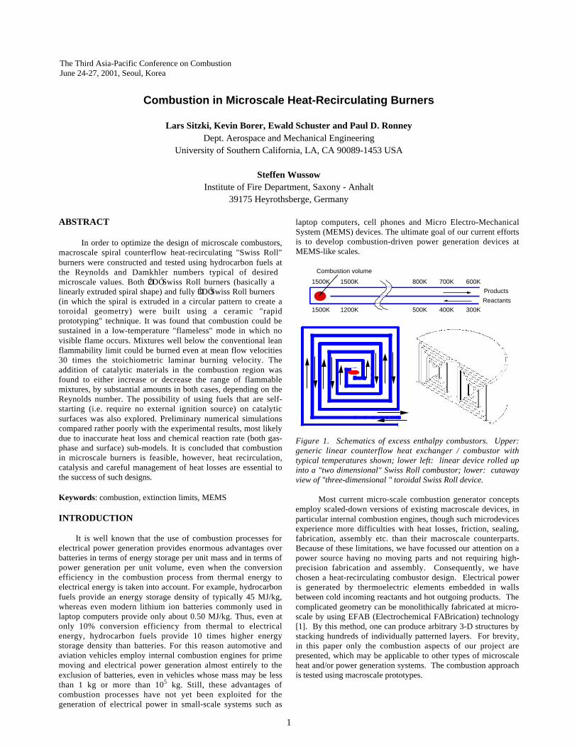
spiral shape) and fully Ò3DÓ burners (in which the spiral isextruded in a circular pattern to create a toroidal geometry) havebeen built. For the macroscale devices, the typical channel sizeof the macroscale test devices is 3 mm vs. 0.13 mm for themicro-scale device we propose. The macro-scale devices (Fig. 2)were built using Solidgen“ rapid prototyping techniques usingsintered alumina-silica with a typical 20 µm pore size (asopposed to the electrochemical process of EFAB). It is readilyshown that with this pore size the inter-turn gas leak-through isnegligible. For the meso-scale test devices (Fig. 3) of typicalchannel dimension 0.4 mm were built using wire electro-discharge machining (EDM). Considerable effort was expendedto find appropriate materials and manufacturing techniques.Since the wire EDM process can only create two-dimensionalextrusion-like structures, end plates are attached for 2D versions,and 6 pie-shaped pieces are butted together to form a quasi-toroidal 3D part. For the meso-scale burners, the combustionchamber region is smaller than 1mm and is therefore smaller thanthe quenching distance for stoichiometric mixtures. A manifoldfor the fresh mixture is attached to the combustors and a frame isused to hold the various parts of the combustor and manifoldtogether.
Figure 2: Images of macroscale burners. Upper left: 2D ÒSwissrollÓ part built using rapid prototyping; lower left: 3D ÒSwissrollÓ half- torus built using rapid prototyping; upper right: 3Dburner (two halves) in experimental configuration; lower right:2D burner in experimental configuration.
A PC with LabView software is used to control mass flowcontrollers for fuel and air and to record data from thermocouplesfor temperature measurement. The exhaust gas composition wasanalyzed with a gas chromatograph. Electrically heated Kantalwire is used for ignition.
EXPERIMENTAL RESULTS
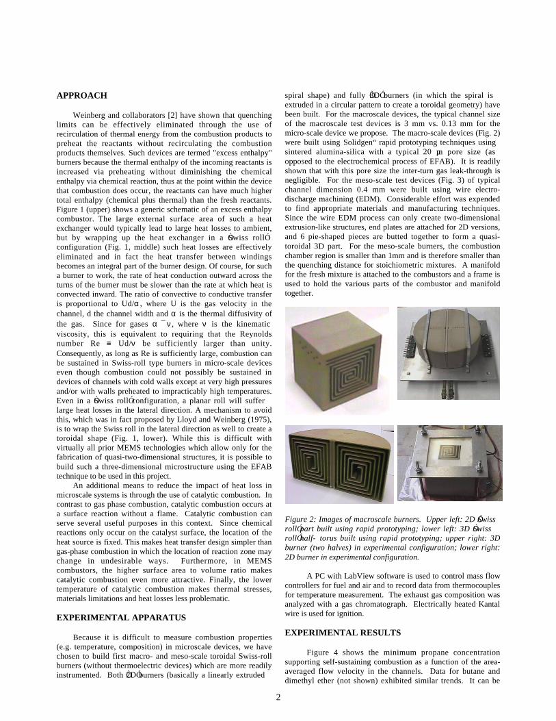
Figure 4 shows the minimum propane concentrationsupporting self-sustaining combustion as a function of the area-averaged flow velocity in the channels. Data for butane anddimethyl ether (not shown) exhibited similar trends. It can be
3
seen in Fig. 4 that mixtures well below the conventional leanflammability limit can be burned even at mean flow velocities 10times the stoichiometric laminar burning velocity (40 cm/s). Thehigh velocity extinction limit is almost certainly due toinsufficient residence time compared to the chemical reactiontime scale (analogous to blowing out a candle flame). These dataare replotted as the fuel enthalpy flux (which is proportional toflow velocity multiplied by the fuel concentration) as a functionof the Reynolds number based on channel width (which isproportional to flow velocity) in Fig. 5. It can be seen that thelower velocity limit corresponds to a constant enthalpy flux, andthus a constant ratio of heat loss to heat generation, which isindicative of a limit due to heat loss. Figure 5 shows thatReynolds number as least as low as 20 can support combustionwith heat recirculation and catalytic combustion (discussed later).
Figure 3: Images of mesoscale burners. Upper left: 2D ÒSwissrollÓ part built using wire EDM; lower left: 3D wedge section;upper right: 3D burner (six wedge-shaped parts); lower right:2D burner in experimental configuration.
Interestingly, it was found that under most conditions, evenwithout catalysts, combustion occurs in a "flameless" mode inwhich no visible flame occurs. Recently other investigators [3]have observed similar behavior in macroscale combustors usinghighly preheated air, though the reason for the differencesbetween flameless and conventional burning have not yet beenestablished. Perhaps even more surprising is that the addition ofplatinum strips as a catalytic material in the combustion regioncan either increase or decrease the range of flammable mixtures,by substantial amounts in both cases, depending on the flowvelocity. This is likely due to the catalyst acting as either a netsource of radicals at low velocities where the residence times arelarge and temperatures are lower, or a net sink of radicals athigher flow velocities where the residence times are shorter andtemperatures higher. Figure 4 shows that nickel and palladiumstrips and copper strips plated with platinum have catalyticactivity, but less than platinum strips.
Figure 6 shows that the minimum temperature supportingcombustion (in the center of the combustor) is much lower whencatalysts are used, less than 200ßC in some cases. Note that evenwithout catalyts, the temperature required to support combustion(typically 800ßC) is lower than that required to supportpropagating flames (typically 1200ßC).
1
1.5
2
2.5
3
3.5
4
10 100 1000
No catalystBulk Pt set #1Bulk Ni
0.4 µm Pt plated on CuBulk PdBulk Pt set #2
Mol
e pe
rcen
t fu
el a
t lim
it
Average inlet velocity (cm/s)
Propane
Conventionallean limit
Figure 4. Effect of area-averaged flow velocity in the 2-Dmesoscale burner on the minimum fuel concentration for self-sustaining combustion.
100
1000
100 1000
No catalystBulk Pt set #1Bulk Ni0.4 µm Pt plated on CuBulk PdBulk Pt set #2E
ntha
lpy
flux
at li
mit
(W)
Reynolds number (Re)
Propane
Figure 5. Same data as Fig. 4, plotted in terms of the inputchemical enthalpy flux as a function of the Reynolds numberbased on channel width.
100
1000
10 100 1000
Propane (no cat)Propane (Pt cat)Propane (Ni cat)Propane (Pd cat)Butane (Pt cat)
Max
imum
tem
pera
ture
(˚C
)
Reynolds number based on channel widthFigure 6. Maximum gas temperature in the macroscale burneras a function of the Reynolds number based on channel width.
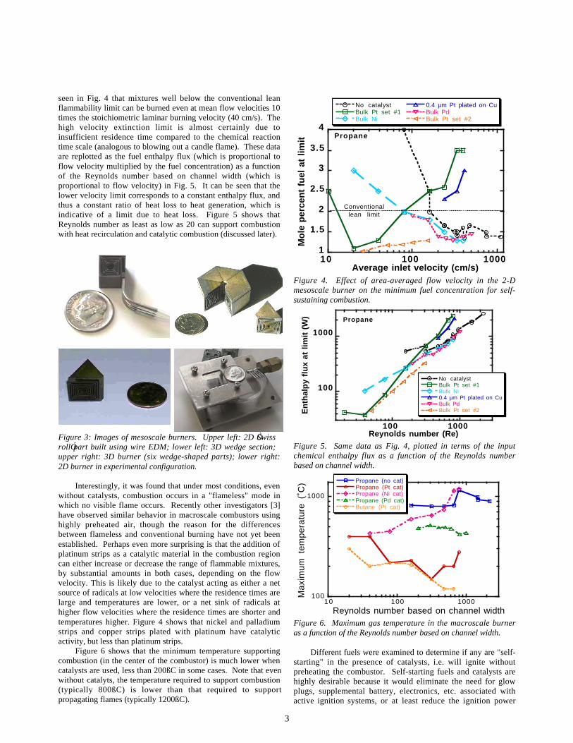
Different fuels were examined to determine if any are "self-starting" in the presence of catalysts, i.e. will ignite withoutpreheating the combustor. Self-starting fuels and catalysts arehighly desirable because it would eliminate the need for glowplugs, supplemental battery, electronics, etc. associated withactive ignition systems, or at least reduce the ignition power
4
requirements. Even if self-starting at room temperature is notachieved, ignition temperatures well below maximum allowabletemperatures for thermoelectric devices have been obtained.Consequently, a set of tests was performed in which the entireburner was heated electrically to a temperature above the desiredtest temperature with air only flowing through the burner, thenthe electrical power was removed and when the temperaturedropped to the target value, the fuel flow was started. Theignition temperature was defined as the minimum temperaturefor which a steady reaction evolved after the fuel flow started.Hydrogen fuel was found to be self-starting even at roomtemperature. Figure 7 shows that dimethyl ether has an ignitiontemperature as low as 120ßC, as compared to 200ßC - 300ßC forbutane and propane. Methane (not shown) was found to have amuch higher starting temperature.
1 0 0
1 5 0
2 0 0
2 5 0
3 0 0
3 5 0
0 5 0 1 0 0 1 5 0 2 0 0 2 5 0 3 0 0 3 5 0
Propane 4%Propane 3%Propane 2%Butane 3.5%DME 7%DME 5%
Ign
itio
n t
em
pe
ratu
re (
˚C)
Flow velocity (cm/s)Figure 7. Minimum self-staring temperature in the 2D Swiss tollburner for various fuels and mixture ratios as a function of flowvelocity.
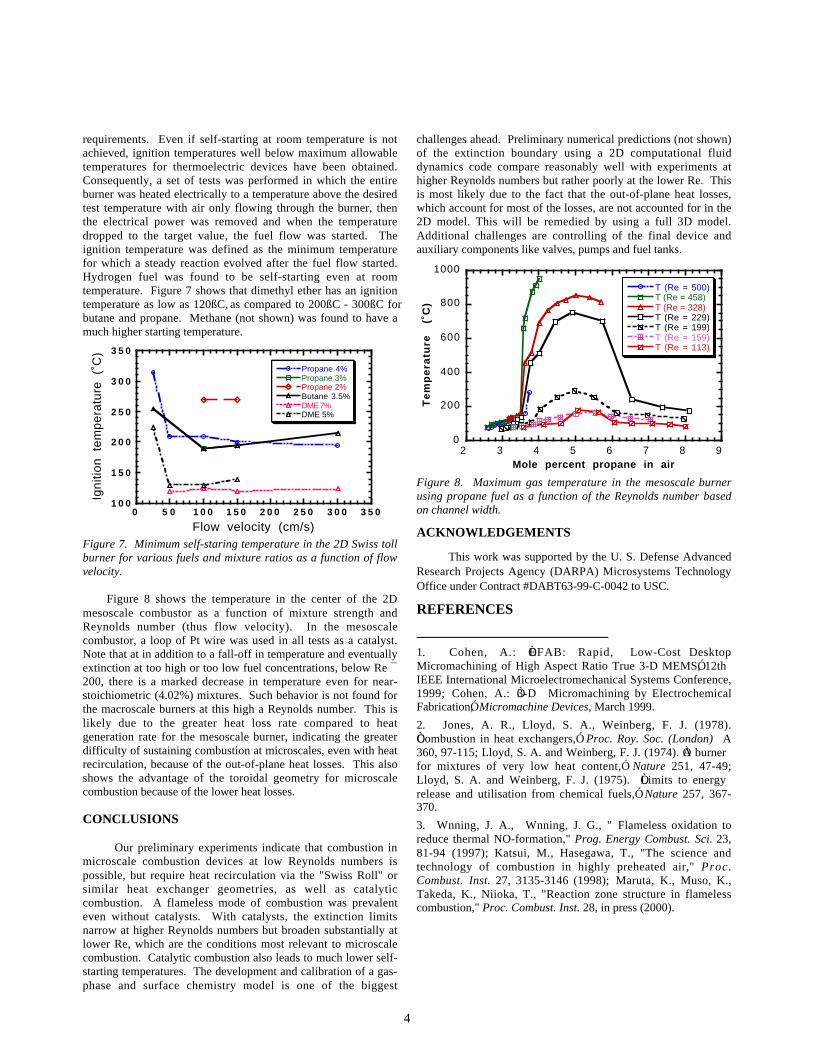
Figure 8 shows the temperature in the center of the 2Dmesoscale combustor as a function of mixture strength andReynolds number (thus flow velocity). In the mesoscalecombustor, a loop of Pt wire was used in all tests as a catalyst.Note that at in addition to a fall-off in temperature and eventuallyextinction at too high or too low fuel concentrations, below Re ¯200, there is a marked decrease in temperature even for near-stoichiometric (4.02%) mixtures. Such behavior is not found forthe macroscale burners at this high a Reynolds number. This islikely due to the greater heat loss rate compared to heatgeneration rate for the mesoscale burner, indicating the greaterdifficulty of sustaining combustion at microscales, even with heatrecirculation, because of the out-of-plane heat losses. This alsoshows the advantage of the toroidal geometry for microscalecombustion because of the lower heat losses.
CONCLUSIONS
Our preliminary experiments indicate that combustion inmicroscale combustion devices at low Reynolds numbers ispossible, but require heat recirculation via the "Swiss Roll" orsimilar heat exchanger geometries, as well as catalyticcombustion. A flameless mode of combustion was prevalenteven without catalysts. With catalysts, the extinction limitsnarrow at higher Reynolds numbers but broaden substantially atlower Re, which are the conditions most relevant to microscalecombustion. Catalytic combustion also leads to much lower self-starting temperatures. The development and calibration of a gas-phase and surface chemistry model is one of the biggest
challenges ahead. Preliminary numerical predictions (not shown)of the extinction boundary using a 2D computational fluiddynamics code compare reasonably well with experiments athigher Reynolds numbers but rather poorly at the lower Re. Thisis most likely due to the fact that the out-of-plane heat losses,which account for most of the losses, are not accounted for in the2D model. This will be remedied by using a full 3D model.Additional challenges are controlling of the final device andauxiliary components like valves, pumps and fuel tanks.
0
200
400
600
800
1000
2 3 4 5 6 7 8 9
T (Re = 500)T (Re = 458)T (Re = 328)T (Re = 229)T (Re = 199)T (Re = 159)T (Re = 113)
Te
mp
era
ture
(˚
C)
Mole percent propane in air
Figure 8. Maximum gas temperature in the mesoscale burnerusing propane fuel as a function of the Reynolds number basedon channel width.
ACKNOWLEDGEMENTS
This work was supported by the U. S. Defense AdvancedResearch Projects Agency (DARPA) Microsystems TechnologyOffice under Contract #DABT63-99-C-0042 to USC.
REFERENCES
1. Cohen, A.: ÒEFAB: Rapid, Low-Cost DesktopMicromachining of High Aspect Ratio True 3-D MEMSÓ, 12thIEEE International Microelectromechanical Systems Conference,1999; Cohen, A.: Ò3-D Micromachining by ElectrochemicalFabricationÓ, Micromachine Devices, March 1999.
2. Jones, A. R., Lloyd, S. A., Weinberg, F. J. (1978).ÒCombustion in heat exchangers,Ó Proc. Roy. Soc. (London) A360, 97-115; Lloyd, S. A. and Weinberg, F. J. (1974). ÒA burnerfor mixtures of very low heat content,Ó Nature 251, 47-49;Lloyd, S. A. and Weinberg, F. J. (1975). ÒLimits to energyrelease and utilisation from chemical fuels,Ó Nature 257, 367-370.
3. W�nning, J. A., W�nning, J. G., " Flameless oxidation toreduce thermal NO-formation," Prog. Energy Combust. Sci. 23,81-94 (1997); Katsui, M., Hasegawa, T., "The science andtechnology of combustion in highly preheated air," Proc.Combust. Inst. 27, 3135-3146 (1998); Maruta, K., Muso, K.,Takeda, K., Niioka, T., "Reaction zone structure in flamelesscombustion," Proc. Combust. Inst. 28, in press (2000).