Embed Size (px)
Citation preview
Copyright ©2012 by CBPCA. All rights reserved. This document or any portion thereof may not be reproduced or used in any
manner whatsoever without the express written permission of the publisher.
Combustion Appliance Safety Testing Guidelines
This guide is intended to assist home performance contractors complete all combustion safety tests
adequately and safely according to the Building Performance Institute (BPI) Building Analyst Technical
Standards (v.1/4/12) along with the Statewide Low Income Program Natural Gas Appliance Testing
(NGAT) PG&E Low Income Program Weatherization Installation Standards, (April 1, 2006). Please refer to
the PG&E Whole House Combustion Appliance Safety Test Procedures, the PG&E Whole House Action
Guidelines and the BPI Technical Standards as needed. Document can be found online at
builditgreenutility.org/document-library and BPI.org.
As stated by BPI, a preliminary and post-installation safety inspection of all combustion appliances must
be completed whenever changes to the building envelope and/or heating system are part of the work
scope. This inspection includes all of the following tests: carbon monoxide (CO) measurement at each
appliance and in ambient air, draft pressure measurement and spillage evaluation for atmospherically
vented appliances, and worst-case negative pressure measurement for each combustion appliance zone
(CAZ). Combustion safety test results must be acted upon according to the Combustion Safety Action Level
table in the BPI Building Analyst Technical Standards (p. 9 of 17). Additional limits outlined in the PG&E
documents above will be described in the relevant sections below.
Please note that all items with an asterisk (*) indicate that a failure in this category requires a call to a
PGE GSR. Consult the EUC Whole House Action Guidelines and Whole House Combustion Appliance
Safety Test Procedure for further details. In addition, statements in italics are quotes from the 17 page
BPI Technical Standards for Certified Building Analyst I; page numbers are given for reference. Refer to
the Technical Standards for further information about BPI standards and procedures.
2 | P a g e California Building Performance Contractors Association, March 2012
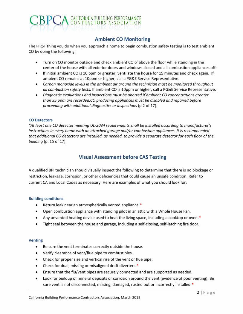
Ambient CO Monitoring The FIRST thing you do when you approach a home to begin combustion safety testing is to test ambient CO by doing the following:
Turn on CO monitor outside and check ambient CO 6’ above the floor while standing in the center of the house with all exterior doors and windows closed and all combustion appliances off.
If initial ambient CO is 10 ppm or greater, ventilate the house for 15 minutes and check again. If ambient CO remains at 10ppm or higher, call a PG&E Service Representative.
Carbon monoxide levels in the ambient air around the technician must be monitored throughout all combustion safety tests. If ambient CO is 10ppm or higher, call a PG&E Service Representative.
Diagnostic evaluations and inspections must be aborted if ambient CO concentrations greater than 35 ppm are recorded.CO producing appliances must be disabled and repaired before proceeding with additional diagnostics or inspections (p.2 of 17).
CO Detectors “At least one CO detector meeting UL-2034 requirements shall be installed according to manufacturer’s instructions in every home with an attached garage and/or combustion appliances. It is recommended that additional CO detectors are installed, as needed, to provide a separate detector for each floor of the building (p. 15 of 17)
Visual Assessment before CAS Testing
A qualified BPI technician should visually inspect the following to determine that there is no blockage or
restriction, leakage, corrosion, or other deficiencies that could cause an unsafe condition. Refer to
current CA and Local Codes as necessary. Here are examples of what you should look for:
Building conditions
Return leak near an atmospherically vented appliance.*
Open combustion appliance with standing pilot in an attic with a Whole House Fan.
Any unvented heating device used to heat the living space, including a cooktop or oven.*
Tight seal between the house and garage, including a self-closing, self-latching fire door.
Venting
Be sure the vent terminates correctly outside the house.
Verify clearance of vent/flue pipe to combustibles.
Check for proper size and vertical rise of the vent or flue pipe.
Check for dual, missing or misaligned draft diverters.*
Ensure that the flu/vent pipes are securely connected and are supported as needed.
Look for buildup of mineral deposits or corrosion around the vent (evidence of poor venting). Be
sure vent is not disconnected, missing, damaged, rusted out or incorrectly installed.*
3 | P a g e California Building Performance Contractors Association, March 2012
Check material of pipe. Identify suspected asbestos-containing materials or masonry that may
cause poor venting.
Make a visual assessment for scorch marks on the outside of the water heater and furnace near
the burner to see if flame rollout may have happened previously. Check for charring of any
combustibles caused by an appliance vent.* If there is evidence of scorching then further testing
should be postponed until a qualified technician has tested the appliance.
NOTE: During back drafting conditions flame roll-out may occur, even if there is no evidence of prior
occurrences.
Furnace
Location: An atmospherically vented furnace cannot be in a bedroom, bedroom closet or bathroom.*
Location: Be sure there is adequate clearance for inspection and servicing.
Location: Verify that there is no fuel or other flammable material stored in the mechanical room
or area and that no combustible material is stored within 2 ft. of the appliance to be tested.
Safety: Be sure that the disconnect or off switch is clearly visible and accessible near the furnace
and look for wires passing through punch outs without grommets or incorrect wiring.
Safety: Look for presence and condition of safety sensors (often absent on old open combustion
furnaces, many wall furnaces and gravity furnaces), be sure the “dead man switch” is functioning
when the panel is removed and replaced. Be sure all doors, inspection covers and roll out shields
are in place.*
Safety: check NOX rod (if present) to be sure it is not touching burners.*
Check for fatigued metal, excessive rust or soot or any other evidence of defective heat
exchanger.
Water Heater
Location: Atmospherically vented water heaters cannot be in bedrooms, bedroom closets or
bathrooms and cannot be outside, unless specified as an exterior type.
Location: Be sure there is adequate clearance for inspection and servicing.
Location: If water heater is in the garage or outside, verify that the platform meets code.
Location: Verify that there is no fuel or other flammable material stored in the mechanical room
or area and that no combustible material is stored within 2 ft. of the appliance to be tested.
Safety: Verify presence of inner and outer burner doors as appropriate.*
Safety: The TPV should NOT be tested, but it should be visibly inspected to be sure it does not
show corrosion and is connected to a relief pipe of appropriate material.
Safety: Check for the safe termination of the relief pipe and evaluate its length, diameter and
downhill run.
Safety: Evaluate the overflow pan, if present.
Safety: Verify seismic straps.
4 | P a g e California Building Performance Contractors Association, March 2012
Safety: Look for evidence of corrosion on water pipes, pipe insulation too close to venting,
especially near the single wall draft diverter, cover over the burner chamber (often lost or left
off).
Check the flame condition for yellow flames (over 50%) or debris or corrosion in or around the
burner compartment.
Fireplaces, Stoves, Ovens, Pool Motors, Wood Stoves, etc.
Any other combustion appliances within the house or in detached buildings should be visually
inspected for potential safety risks.
When possible, turn on appliance and check for smooth functioning (working controls, proper
flame color and size, etc). When not possible to turn on, discuss the appliance with the
occupants to determine whether there is a safety concern.
If the appliance is vented, look for vent termination, vent material, damper function and anything
else that is accessible to identify potential problems.
Look for evidence of flame rollout or backdrafting, and identify any flammable or combustible
materials in the vicinity.
The primary question to ask yourself during a visual assessment is; Does this look like it might be a safety
concern? If so, investigate further or consult an expert (you may want to carry a CODE CHECKER for
general guidance).
Gas Supply Safety
The entire gas/propane line must be examined and all leaks repaired.
Particular care should be made in the immediate vicinity of the appliances and at the joints,
shutoff valves and pilot lines.
Identify leaks using a gas leak detector and accurately locate the source of the leak using a soap
bubble solution.*
Flexible gas lines must be replaced if they are: kinked, corroded or show signs of visible wear, the
line was manufactured before 1973 (date is stamped on the date ring attached to the line), or the
line has any soldered connections (p.11 of 17).*
Check for uncapped gas lines.*
If aldehyde odor is detected, contact a GSR.*
5 | P a g e California Building Performance Contractors Association, March 2012
Worst Case Depressurization
Worst Case Depressurization should be done to test the maximum depressurization that can occur in a
combustion appliance zone (CAZ) due to normal occupant behavior. First, identify the combustion
appliance zones based on the location of the furnace(s) and water heater(s) (and any other vented
combustion appliance to be tested).
Combustion Appliance Zone (CAZ)
A combustion appliance zone (CAZ) is the room in which any natural or induced draft or direct vented space heating system, gas log fireplace or water heater resides. The room must have a door that closes, such as a garage, closet or laundry room. Buildings that are detached from the living space do not need to be tested for Worst Case Depressurization. Back up heating units do not need to be tested. Confined Space and Combustion Ventilation Air (CVA) Any zone with a Category I appliance (such as a natural draft water heater or a natural or induced draft furnace), including abandoned appliances, whether attached to the living space or not, must be evaluated for adequate combustion air. If a Category IV appliance (such as a condensing furnace) is installed in such a way that it draws its combustion air from the CAZ, it must also be evaluated for adequate combustion air. The volume of any CAZ must be at least 50 cubic feet per 1000 BTU of combustion appliance operating in that room. If the space is smaller than this, it is considered a confined space and adequate make-up air must be provided according to Code. See CVA calculation section at end for guidance on how to ensure adequate make-up air is being provided. Prepare House for Worst Case Here are recommended house configurations for preparing house for a worst case depressurization test: House Features Configuration______________ Exterior windows Closed and latched Exterior doors Closed and latched Doors on an enclosed furnace/water heater utility room Closed and latched Interior doors Open Register dampers Open (except in utility room with gas appliance) Furnace filter Removed Woodstove or fireplace No fire: close doors and air control dampers Fuel-fired appliances (furnace, boiler, space heater, water heater, stove, oven, gas fireplace, pellet stove) Turn down thermostats, turn off, or turn to pilot Exhaust and supply fans Off Ventilating and air moving devices Off Clothes dryer Off Attic hatch Closed Crawl space/basement Hatch/door Closed Broken windows and other short term openings Taped over Sub-slab ventilation fans or subfloor ventilation systems for soil gas control Turned off
6 | P a g e California Building Performance Contractors Association, March 2012
Measure the Base Pressure
With the home in the above configuration, measure and record the base pressure of the combustion appliance zone (CAZ) with reference to (wrt) outside.
Establish the Worst Case (p. 12 of 17)
Turn on the dryer, and all exhaust fans except Whole House Fans. Close interior doors that make the CAZ pressure more negative. If CAZ is the garage, check garage door as well. Measure and record the pressure from the CAZ to outside.
Turn on the air handler, if present, and leave on if the pressure in the CAZ becomes more negative, then recheck the door positions, leaving all doors closed that make the CAZ more negative. If CAZ is the garage, check garage door as well. Measure and record the pressure from the CAZ to outside.
Compare fans-only measurement to air handler and fans measurement and determine which created the most negative depressurization. Using the most negative result, correct for base pressure and record the Worst Case Depressurization.
Compare to the CAZ Depressurization Limits table on page 14 of BPI Building Analyst Technical Standards. Note: there are no depressurization limits established for gas log fireplaces.
When CAZ depressurization limits are exceeded under worst-case conditions according to the CAZ Depressurization Limits table, make up air must be provided or other modifications to the building shell or exhaust appliances must be included in the work scope to bring the depressurization within acceptable limits (p.14 of 17).
Reminder: Monitor the ambient CO in the breathing zone during the test procedure. Contact a GSR if ambient CO readings are 10 ppm or greater.
Combustion Appliance Safety Testing Spillage and draft tests must be completed for all natural and induced draft space heating systems and water heaters, first under worst case conditions. With the exception of unvented gas or propane cooking appliances, direct vented appliances with inaccessible terminations and dryers, CO must be tested in all combustion appliances under Worst Case conditions (p.10 or 17). Unvented gas or propane cooking appliances and dryers should be tested for CO generation under normal conditions as described below.
Measure Worst Case Spillage, Draft, CO for vented combustion appliances
Under Worst Case Depressurization conditions, fire the appliance with the smallest input first. Inspection of flames:
Check for delayed ignition (an explosion when the flames ignite) and yellow flames (over 50%).
Check for short cycling of the main burner on the furnace.*
Forced warm air furnaces must be inspected for flame interference. * Visually inspect the burner
as the blower fan comes on. If the flames burn differently when the blower comes on, a complete
analysis needs to be done to find the source of the flame interference. This problem must be
referred to a heating contractor. A cracked heat exchanger cannot effectively be repaired and
must be replaced (p.15 of 17).
7 | P a g e California Building Performance Contractors Association, March 2012
Spillage:
Test for spillage at the draft diverter with a mirror or smoke test. For fireplace, test at the upper lip of the fireplace opening.
Document the amount of time it takes for spillage to stop and a positive draft to be established. Any appliance that continues to spill flue gases for more than 5 minutes after startup fails the spillage test (p.11 of 17).*
Draft:
Using the static pressure tip, test the draft in the vent or flue pipe 1-2’ after the diverter or first elbow. Fireplaces do not need to be tested for draft pressure.
Record Draft Pressure. Vent draft pressure shall be measured at steady state operating conditions for all natural draft heating and hot water appliances (p.10 of 17). This is approximately 5 – 15 minutes after the burner goes on.
Compare the measured draft pressure to the minimum draft pressure standard (based on the table on page 10 of 17).
Do not drill holes in flues for power vented or sealed combustion units (p.9 of 17).
CO:
Test for CO using the “Air Free” setting at the flue at steady state (approximately 5 – 15 minutes after the burner goes on).
CO shall be measured of undiluted flue gases, in the throat or flue of the appliance using a digital gauge and measured in parts per million (ppm). (p. 9 of 17). For direct vented appliances, test for exhaust CO at the termination of the flue, if accessible.*
Measure exhaust CO for a gas log fireplace 12” above the flame.* Ambient CO:
Test for ambient CO above the appliance and around the draft diverter at steady state (after appliance has been running for 5-15 minutes). For Forced Air Furnace or Gravity Furnace, test for ambient CO in the supply closest to the furnace.*
Repeat tests for each appliance, in order of increasing input rate, making sure tests are performed under Worst Case Depressurization for each CAZ. After all appliances have been tested individually, test them simultaneously ONLY IF they share a vent or flue. Be sure to allow the vent or flue to cool between tests. See below for the procedure for testing spillage on commonly vented appliances:
If appliances share a vent, fire them simultaneously and test the draft diverter of each appliance for spillage (p.12 of 17).
If a chimney is shared between an induced draft heating system and a natural draft water heater, spillage shall be checked at the water heater draft diverter (p.10 of 17).
If a sampling hole was drilled, use a plug, screw or fire calking to seal it and return all thermostats to the occupants’ original setting.
8 | P a g e California Building Performance Contractors Association, March 2012
Action Levels Make recommendations or complete work order for repairs based on test results and the Combustion Safety Test Action Level Tables on page 13 (p.12 of 17). Call a PGE Gas Service Representative (GSR) if any of the following occur:
1. Ambient CO is 10 ppm or greater. 2. Ambient CO in supply closest to furnace is 2ppm or greater above room ambient. 3. Flue CO in vented appliance is 101 ppm or greater at steady state. 4. Exhaust CO 12” above a gas log fireplace is 26 ppm or greater.
Measure CO for unvented combustion appliances
No unvented combustion appliances may operate in the living space with the exception of gas cooktops/ovens (CA Code). According to BPI, exhaust ventilation must always be recommended whenever a gas or propane cooking appliance exists. If a range hood will be installed as part of the job scope, it must meet ASHRAE 62.2, which requires a minimum 100 CFM intermittent or the capacity to exhaust 5 ACH of the kitchen volume without exceeding 3 sones. Gas Oven Testing CO shall be measured at steady state (usually after 5-10 minutes of operation) at the highest setting. When measuring CO on gas ovens, it is recommended to turn on the exhaust hood and open a window to reduce risk of exposure to elevated ambient CO levels (p.10 of 17).
Remove any items/foil in or on oven.
Make sure self-cleaning features are not activated, set oven to highest setting.
Check ambient CO 6’ above the floor in the center of the room when the oven is operating at steady state (after approximately 5 minutes).
Test oven for CO in the flue, before dilution air.
Check broiler separately as needed
If oven or broiler exhaust CO is 226 ppm or greater at steady state, a GSR must be called. Refer to the Action Levels on Page 15 of the BPI Building Analyst Technical Standards for results of Oven CO tests. Gas Cooktop Testing Since all gas cooktops generate CO and it is difficult to simulate an actual operating condition for these appliances during the course of a typical house inspection, specific action levels for these burners are not specified by BPI. When measuring CO on gas cooktops, it is recommended to turn on the exhaust hood or open a window to reduce risk of exposure to elevated ambient CO levels.
Turn on all burners and measure ambient CO 6’ above the floor in the center of the room after one minute of operation.
Turn on burners one at a time and check for exhaust CO 12” above the flame.
If gas cooktop exhaust CO is 26 ppm or greater at steady state, a GSR must be called. Technicians must specify appropriate measures to mitigate potentially dangerous CO production of these units
9 | P a g e California Building Performance Contractors Association, March 2012
ASHRAE exposure limits for CO shall be referenced when making recommendations for CO control in these areas (The recommended ASHRAE limit for 24-hour exposure of 9 ppm shall be applied to building occupants).
If burners do not ignite properly or do not burn cleanly, a clean and tune of the appliance shall be recommended.
If the appliance is located in a confined space and mechanical ventilation is not readily available, mechanical ventilation shall be recommended (p. 15 of 17)
Measure CO for Dryer
Gas dryers should be checked for ambient CO and exhaust CO. Be sure dryer vents to the outside.
Check ambient CO above the unit after it has been operating for 5 minutes.
Check exhaust CO using the “Air Free” setting at the termination of the dryer outside the house, if accessible.
CO Limit Table for calling a GSR
Ambient CO
Whole house, natural conditions 10 ppm
Water heater, gas dryer, cooktop, oven, broiler 10 ppm
Forced air furnace Room ambient + 2ppm
Exhaust CO
Space and Water heaters and Gas Dryers 101 ppm “Air Free” under Worst Case Depressurization
Cooktop, Gas Log Fireplace 26 ppm
Oven, broiler 226 ppm
Combustion Ventilation Air (CVA) CVA requirements only apply to open combustion furnaces and water heaters. Abandoned appliances (capped off
or disconnected only) must be included in CVA or room volume calculations. Heating appliances with flex gas
connector removed, the gas line shut off, valve capped or valve removed and pipe capped are considered
abandoned.
Confined Space - Is an area designed for the operation of combustion appliances which has a total volume of less than 50 cubic ft. per 1000 Btu’s input of all open combustion furnaces/heaters and water heaters within the space. Procedure for Determining if an Open Combustion Appliance is Located in a Confined Space
1. Measure enclosure or room: L X W X H = Existing Area in Cubic Feet. 2. Determine the required volume of the room:
Total Btu’s divided by 1000 times 50 cubic feet = Required Cubic Feet. A shortcut to get the same answer is: Divide the total Btu input by 2, then drop the last zero. Example: 44,000 total Btu input divided by 2 = 22,000. Drop the last zero = 2,200 cu. ft.
3. If the result of 1 is less than the result of 2, additional Combustion Ventilation Air (CVA) is required. 4. If the result of 1 is equal to or greater than 2, CVA is not required.
10 | P a g e California Building Performance Contractors Association, March 2012
CVA Calculation Rules You determine the required size of each opening by taking the total Btu input of all the open combustion appliances in the zone and divide by 1000. Take the results and divide by the CVA Rule you have chosen to use. Example: The total input is 80,000 Btu. You have chosen rule 4. 80,000 divided by 1000 = 80. 80 divided by rule 4 = 20 sq. in. That means you are required to install openings with 20 square inches of Net Free Venting Area for each opening, in this case 1 upper and 1 lower vent or vertical duct. Refer to the Vent Opening Multipliers below for approximate reductions to net free venting area caused by louvers and screens over the openings. Note: Any combustion air coming through a vent or duct to the attic must not have a screen. To prevent insulation from falling through an opening in the attic floor, it must have a dam that extends at least 6” above the level of attic insulation. If a duct is used to allow ventilation air from the attic, the duct must extend at least 6” above the level of attic insulation. Rule 1: Requires two openings. CVA from conditioned space requires that each opening shall have a NFV area of at least 1 sq. in. for every 1000 Btu’s input. 1 upper vent within 12” of ceiling and 1 lower vent within 12” of floor venting to unconfined space. Each opening, Minimum 100 sq. In. Rule 2: Requires two openings. CVA supplied by horizontal ducts to the outside (unconditioned space). 1 upper duct and 1 lower duct. Each opening requires a NFV area of at least 1 sq. in. for every 2000 Btu’s input. Rule 3: Requires one opening. CVA to outside (unconditioned space) 1 upper opening (or vertical or horizontal duct) may be used to provide the combustion air. The vent/duct must provide 1 sq. in NFVA per 3,000 Btu’s input The combustion appliance must have 1” clearance on the sides and 6” clearance in front from appliance to wall / door. Rule 4: Requires two openings. CVA to the outside (unconditioned space) 1 upper and 1 lower vent or vertical duct opening is required. Each opening shall have a NFV area of a least 1 sq. in. for every 4000 Btu’s input. Note: In an unconditioned garage when it is considered a confined space, 1 vent either upper and/or lower, equal to 1sq. in per 4,000 btu input for all applicable appliances is OK. The CVA opening can either be already installed, or installed by the WS Contractor. Must be designed CVA. Note: If an AWH or furnace is in an enclosure that has non-standard doors (pocket, accordion, etc.) which are not feasible to weatherstrip, it is OK to not weatherstrip the doors, and in addition install or increase CVA to outside if necessary.
AREA OF A CIRCLE (sq. in.) Area of a Circle = Radius X Radius X 3.14 Radius = Half the diameter 3” diameter circle = 7.1 sq. in. 4” diameter circle = 12.6 sq. in. 5” diameter circle = 19.6 sq. in. 6” diameter circle = 28.3 sq. in. 7” diameter circle =38.5 sq. in. 8” diameter circle = 50.3 sq. in. 9” diameter circle =63.6 sq. in. 10” diameter circle = 78.5 sq. in. 12” diameter circle = 113 sq. in.
11 | P a g e California Building Performance Contractors Association, March 2012
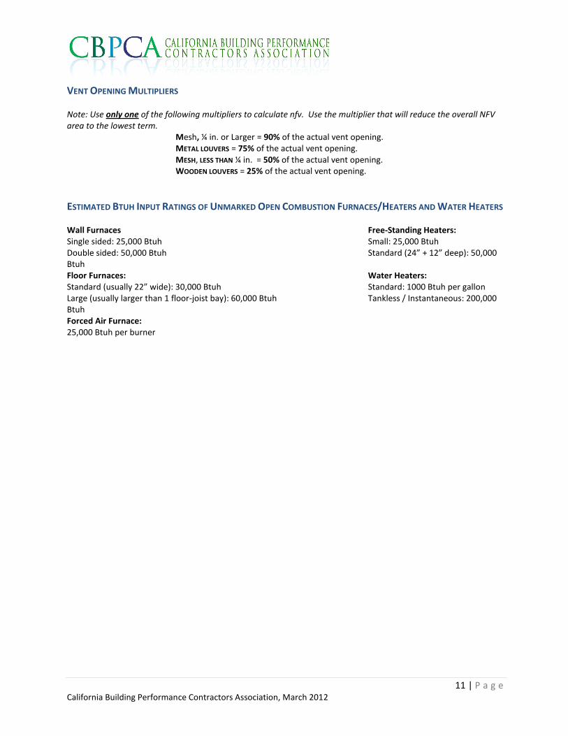
VENT OPENING MULTIPLIERS Note: Use only one of the following multipliers to calculate nfv. Use the multiplier that will reduce the overall NFV area to the lowest term.
Mesh, ¼ in. or Larger = 90% of the actual vent opening. METAL LOUVERS = 75% of the actual vent opening. MESH, LESS THAN ¼ in. = 50% of the actual vent opening. WOODEN LOUVERS = 25% of the actual vent opening.
ESTIMATED BTUH INPUT RATINGS OF UNMARKED OPEN COMBUSTION FURNACES/HEATERS AND WATER HEATERS
Wall Furnaces Free-Standing Heaters: Single sided: 25,000 Btuh Small: 25,000 Btuh Double sided: 50,000 Btuh Standard (24” + 12” deep): 50,000 Btuh Floor Furnaces: Water Heaters: Standard (usually 22” wide): 30,000 Btuh Standard: 1000 Btuh per gallon Large (usually larger than 1 floor-joist bay): 60,000 Btuh Tankless / Instantaneous: 200,000 Btuh Forced Air Furnace: 25,000 Btuh per burner
12 | P a g e California Building Performance Contractors Association, March 2012
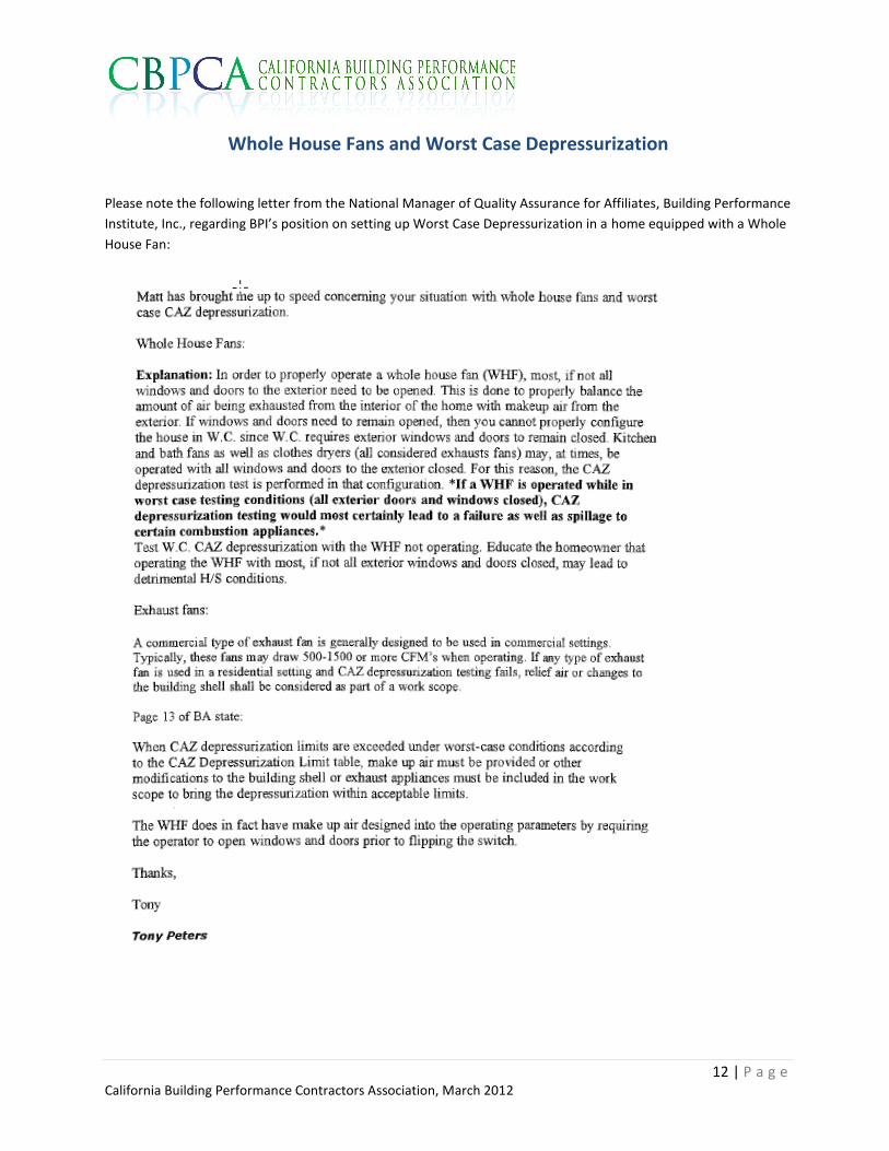
Whole House Fans and Worst Case Depressurization
Please note the following letter from the National Manager of Quality Assurance for Affiliates, Building Performance
Institute, Inc., regarding BPI’s position on setting up Worst Case Depressurization in a home equipped with a Whole
House Fan: