Embed Size (px)
Citation preview
2017.06 panasonic.net/id/pidsx/global
Communication Unitfor CC-Link IE Field / CC-Link
SC-GU3-04 / SC-HG1-CEFSC-GU3-01 / SC-HG1-C
Real-time communication for various sensors
Introducing the industry's first* communication units compatible with CC-Link IE Field* As of March 2017, in-company survey
FX-500 SERIES
Digital fiber sensorLS-500 SERIES
Digital laser sensor
PM SERIES
Micro photoelectric sensor
HG-S SERIES
Contact-type digital displacement sensor
GA-311 SERIES
Compact inductive proximity sensor (amplifier-separated) KT SERIES
Temperature controller
HG-C SERIES
Micro laser distance sensor
Connect Fiber Sensors and Displacement
Sensors to for High-Speed Control
Head-separated digital pressure sensorDPS-400 SERIES
Rectangular-shaped inductive proximity sensor (amplifier built-in)GX-F/H SERIES
2
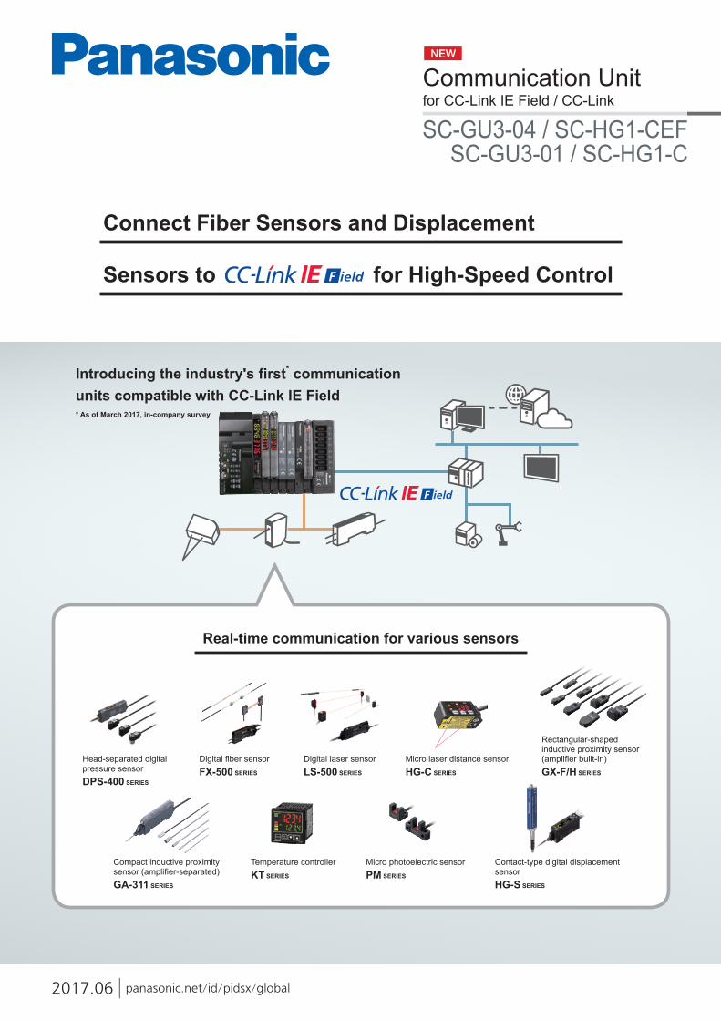
Each SC-GU3 series unit can be connected with up to 16 sensors*.
Transmission of digital (numerical) data from pressure sensors, photoelectronic sensors, laser sensors, temperature controllers, and the like to the network
Transmission of ON/OFF data of proximity sensors and other sensors to the network
* Up to 12 units when the system is configured with FX-500 series / LS-501 unit
SC-GU3-04
Communication speed: 1 Gbps
Communication unit for CC-Link IE Field
Communication Unit for Open NetworkSC series
Panasonic Industrial Device SUNX's sensors can connect to both!
Communication speed: 10 Mbps (max.)
SC-GU3-01 Communication unit for CC-Link
FX-500 SERIES
HG-C SERIES
LS-500 SERIES PM SERIES
GA-311/GH SERIES
GX-F/H SERIES
DPS-400 SERIESDPH-100 SERIES
KT SERIES
Digital fiber sensor
Micro laser distance sensor*
Digital laser sensor Micro photoelectric sensor*
Head-separated digital pressure sensor
Setting of sensor threshold values and operation / confirmation of current values can be performed on the network. This eliminates the need to directly operating individual sensor units.
The ON/OFF data of sensors can be centrally managed on the network. Should an abnormality occur, the problem cause can be easily identified and located.
* SC-A01 analog voltage input unit or SC-A02 analog current input unit is also required.
* SC-E1 1-channel connector input extension unit or SC-E81 / SC-E82 8-channel connector input extension unit is also required.
Units with a pressure range of 1 MPa, ±100 kPa and -101 kPa are available.
Conditions surrounding the manufacturing industry are rapidly changing as production processes are advancing dramatically based on keywords such as IoT and Industry 4.0. To respond to the IoT trend, "visualization" is the first step to take. Panasonic Industrial Device SUNX offers sensors and communication units that achieve the acquisition and visualization of sensor data.
Five types of IP67G sensor head models are available, including an ultra-compact unit with a diameter of 2.8 mm 0.110 in and a sputter-resistant unit.
These inductive proximity sensors have a large stable detection range to provide an ample detection distance.The integrally molded construction realizes IP68G protection.
These compact units feature three protective circuits. A large, easy-to-see multi-angle indicator is provided.
More than 100 types of fiber heads, including a heat-resistant type, chemical-resistant type and lens-equipped type, are available.
Four types of sensor heads, such as a thru-beam type, coaxial reflective type and coaxial retroreflective type, are available.
The CMOS laser sensors offer repeatability of 10 μm 0.394 mil to ensure stable detection.
This unit is easy to operate and realizes high-precision temperature control.
Temperature controller*
Compact inductive proximity sensor (amplifier-separated)
Rectangular-shaped inductive proximity sensor (amplifier built-in)*
Connection of various sensors to the network
●Fiber sensors●Pressure sensors ● Displacement sensors
●Laser sensors
Visualize collected sensor data to launch IoT initiatives!
3
High-precision data
High-precision data
Equipment maintenance and management
Cloud server
CC-Link IE Field Communication UnitSC-GU3-04
CC-Link IE Field Communication Unit for HG seriesSC-HG1-CEF
DisplayPLC
PLC Master PLC MasterPLC LocalHub
Production instruction terminal
Production execution system
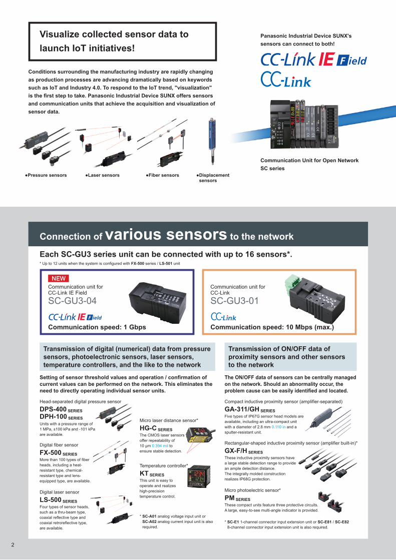
The SC-HG1 series achieves programless transmission of high-precision data.Internal settings of multiple units can also be changed in a batch via the network.
Each SC-HG1 series unit can be connected with up to 15 displacement sensors.
Connection of displacement sensors to the network
Maximum station-to-station distance: 100 m 328.084 ft
CC-Link Master
Connection of 1 master unit and up to 14 slave units
Transmission of digital (numerical) data from contact-type digital displacement sensors to the network
Communication speed: 10 Mbps (max.)
SC-HG1-C
CC-Link Communication Unit for HG series
SC-HG1-CEF
CC-Link IE Field Communication Unit for HG series
Communication speed: 1 Gbps
HG-S SERIES
Use of the communication unit enables the connection of various Panasonic Industrial Device SUNX sensors to a CC-Link network for the real-time acquisition of digital data and ON/OFF data. This allows you to change sensor settings via the network and also log data for preventive maintenance purposes.
The robust and slim unit body contributes to long service life.The series uses the optical absolute system to eliminate the problems of "value skipping" and "missing zero point."
Contact-type digital displacement sensor
CC-Link Communication Unit for HG seriesSC-HG1-C
CC-Link Communication UnitSC-GU3-01
Communication unit for direct connection of sensors to the network!
4
しきい値1ch
現在値90 65
2ch 50 03ch 40 704ch 0 05ch 0 06ch 0 07ch 0 08ch 0 0
しきい値9ch
現在値0 0
10ch 0 011ch 0 012ch 0 013ch 0 014ch 0 015ch 0 016ch 0 0
W4L
V4L
U4L
W2
W4L
V4L
U4L
W2
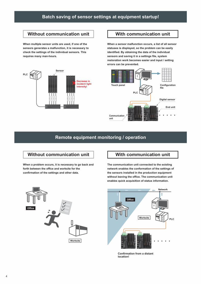
Batch saving of sensor settings at equipment startup!
Remote equipment monitoring / operation
When multiple sensor units are used, if one of the sensors generates a malfunction, it is necessary to check the settings of the individual sensors. This requires many man-hours.
Sensor
Touch panel Configurationfile
PLC
PLC
Digital sensor
Communicationunit
End unit
Decrease in incident light intensity!
When a problem occurs, it is necessary to go back and forth between the office and worksite for the confirmation of the settings and other data.
When a sensor malfunction occurs, a list of all sensor statuses is displayed, so the problem can be easily identified. By obtaining the data of the individual sensors and saving it in a settings file, system restoration work becomes easier and input / setting errors can be prevented.
The communication unit connected to the existing network enables the conformation of the settings of the sensors installed in the production equipment without leaving the office. The communication unit enables quick acquisition of status information.
Network
PLC
With communication unit
With communication unit
Without communication unit
Without communication unit
Office
Office
Worksite
Confirmation from a distant location!
Worksite
5
W4L
V4L
U4L
W2
W4L
V4L
U4L
W2
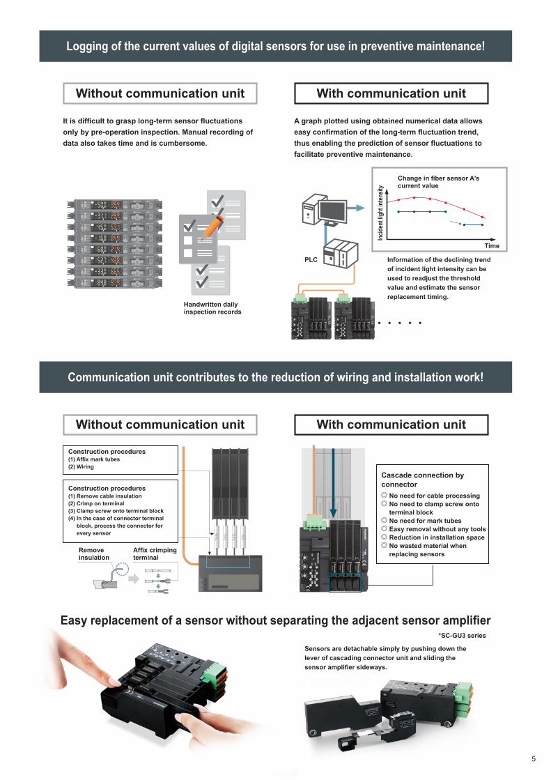
Logging of the current values of digital sensors for use in preventive maintenance!
Communication unit contributes to the reduction of wiring and installation work!
It is difficult to grasp long-term sensor fluctuations only by pre-operation inspection. Manual recording of data also takes time and is cumbersome.
PLC
Handwritten daily inspection records
Remove insulation
Affix crimping terminal
Time
Information of the declining trend of incident light intensity can be used to readjust the threshold value and estimate the sensor replacement timing.
Sensors are detachable simply by pushing down the lever of cascading connector unit and sliding the sensor amplifier sideways.
*SC-GU3 series
A graph plotted using obtained numerical data allows easy confirmation of the long-term fluctuation trend, thus enabling the prediction of sensor fluctuations to facilitate preventive maintenance.
Change in fiber sensor A's current value
Incid
ent l
ight
inte
nsity
With communication unit
With communication unit
Without communication unit
Without communication unit
Easy replacement of a sensor without separating the adjacent sensor amplifier
Cascade connection by connector
No need for cable processing No need to clamp screw onto terminal block
No need for mark tubes Easy removal without any tools Reduction in installation space No wasted material when replacing sensors
Construction procedures(1) Remove cable insulation(2) Crimp on terminal(3) Clamp screw onto terminal block(4) In the case of connector terminal
block, process the connector for every sensor
Construction procedures(1) Affix mark tubes(2) Wiring
6
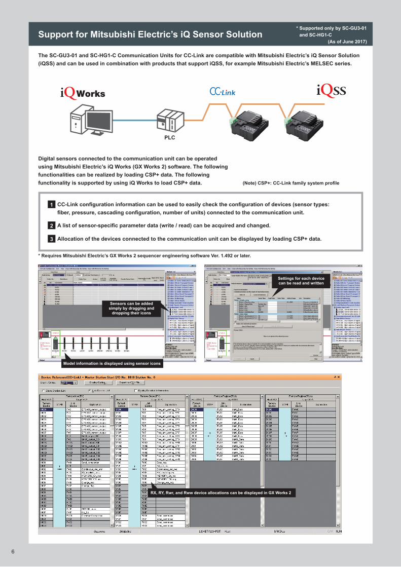
Support for Mitsubishi Electric’s iQ Sensor Solution* Supported only by SC-GU3-01
and SC-HG1-C(As of June 2017)
The SC-GU3-01 and SC-HG1-C Communication Units for CC-Link are compatible with Mitsubishi Electric’s iQ Sensor Solution (iQSS) and can be used in combination with products that support iQSS, for example Mitsubishi Electric’s MELSEC series.
CC-Link configuration information can be used to easily check the configuration of devices (sensor types: fiber, pressure, cascading configuration, number of units) connected to the communication unit.
A list of sensor-specific parameter data (write / read) can be acquired and changed.
Allocation of the devices connected to the communication unit can be displayed by loading CSP+ data.
* Requires Mitsubishi Electric’s GX Works 2 sequencer engineering software Ver. 1.492 or later.
Digital sensors connected to the communication unit can be operated using Mitsubishi Electric’s iQ Works (GX Works 2) software. The following functionalities can be realized by loading CSP+ data. The following functionality is supported by using iQ Works to load CSP+ data. (Note) CSP+: CC-Link family system profile
1
2
3
PLC
Sensors can be added simply by dragging and
dropping their icons
Model information is displayed using sensor icons
Settings for each device can be read and written
RX, RY, Rwr, and Rww device allocations can be displayed in GX Works 2
7
.csv
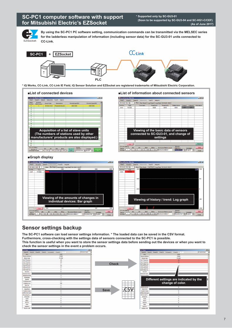
* Supported only by SC-GU3-01 (Soon to be supported by SC-GU3-04 and SC-HG1-C/CEF)
(As of June 2017)
SC-PC1 computer software with support for Mitsubishi Electric’s EZSocket
Sensor settings backup
By using the SC-PC1 PC software setting, communication commands can be transmitted via the MELSEC series for the ladderless manipulation of information (including sensor data) for the SC-GU3-01 units connected to CC-Link.
The SC-PC1 software can load sensor settings information. * The loaded data can be saved in the CSV format.Furthermore, cross-checking with the settings data of sensors connected to the SC-PC1 is possible.This function is useful when you want to store the sensor settings data before sending out the devices or when you want to check the sensor settings in the event a problem occurs.
■List of connected devices
* iQ Works, CC-Link, CC-Link IE Field, iQ Sensor Solution and EZSocket are registered trademarks of Mitsubishi Electric Corporation.
■List of information about connected sensors
■Graph display
+SC-PC1 EZSocket
Acquisition of a list of slave units(The numbers of stations used by other
manufacturers' products are also displayed.)
Viewing of the basic data of sensors connected to SC-GU3-01, and change of
settings
Viewing of the amounts of changes in individual devices: Bar graph Viewing of history / trend: Log graph
Check
Save
PLC
Different settings are indicated by the change of color.
8
Display PLC Free downloads
GOT1000 series (Mitsubishi Electric Corporation) Mitsubishi Electric Corporation
Available for download from the Mitsubishi Electric and Panasonic Industrial Devices SUNX websites
GOT2000 series(Mitsubishi Electric Corporation) Mitsubishi Electric Corporation
Soon to be available for download from the Panasonic Industrial Devices SUNX website
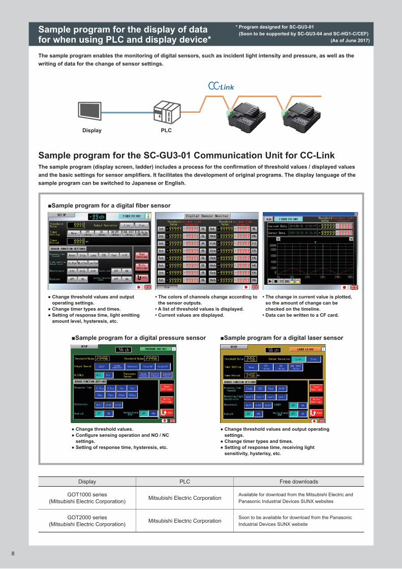
Sample program for the SC-GU3-01 Communication Unit for CC-Link
The sample program enables the monitoring of digital sensors, such as incident light intensity and pressure, as well as the writing of data for the change of sensor settings.
The sample program (display screen, ladder) includes a process for the confirmation of threshold values / displayed values and the basic settings for sensor amplifiers. It facilitates the development of original programs. The display language of the sample program can be switched to Japanese or English.
● Change threshold values and output operating settings.
● Change timer types and times.● Setting of response time, light emitting
amount level, hysteresis, etc.
● Change threshold values.● Configure sensing operation and NO / NC
settings.● Setting of response time, hysteresis, etc.
● Change threshold values and output operating settings.
● Change timer types and times.● Setting of response time, receiving light
sensitivity, hysterisy, etc.
• The colors of channels change according to the sensor outputs.
• A list of threshold values is displayed.• Current values are displayed.
• The change in current value is plotted, so the amount of change can be checked on the timeline.
• Data can be written to a CF card.
Sample program for the display of data for when using PLC and display device*
■Sample program for a digital fiber sensor
■Sample program for a digital pressure sensor ■Sample program for a digital laser sensor
PLCDisplay
* Program designed for SC-GU3-01 (Soon to be supported by SC-GU3-04 and SC-HG1-C/CEF)
(As of June 2017)
9
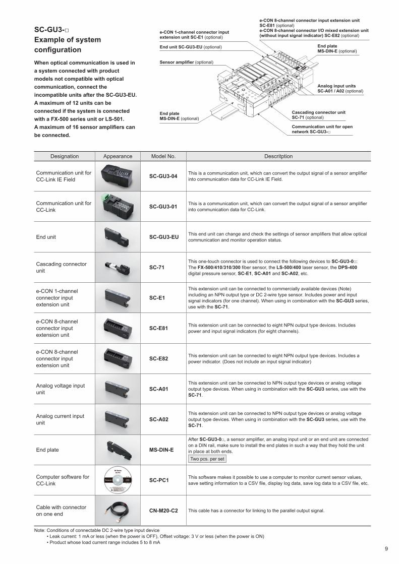
When optical communication is used in a system connected with product models not compatible with optical communication, connect the incompatible units after the SC-GU3-EU.A maximum of 12 units can be connected if the system is connected with a FX-500 series unit or LS-501. A maximum of 16 sensor amplifiers can be connected.
SC-GU3-□Example of system configuration
End plate MS-DIN-E (optional)
End plate MS-DIN-E (optional)
Cascading connector unit SC-71 (optional)
Sensor amplifier (optional)
e-CON 1-channel connector input extension unit SC-E1 (optional)
Analog input units SC-A01 / A02 (optional)
e-CON 8-channel connector input extension unit SC-E81 (optional)e-CON 8-channel connector I/O mixed extension unit (without input signal indicator) SC-E82 (optional)
End unit SC-GU3-EU (optional)
Communication unit for open network SC-GU3-□
Designation Appearance Model No. Descritption
Communication unit for CC-Link IE Field SC-GU3-04 This is a communication unit, which can convert the output signal of a sensor amplifier
into communication data for CC-Link IE Field.
Communication unit for CC-Link SC-GU3-01 This is a communication unit, which can convert the output signal of a sensor amplifier
into communication data for CC-Link.
End unit SC-GU3-EU This end unit can change and check the settings of sensor amplifiers that allow optical communication and monitor operation status.
Cascading connector unit SC-71
This one-touch connector is used to connect the following devices to SC-GU3-0□:The FX-500/410/310/300 fiber sensor, the LS-500/400 laser sensor, the DPS-400 digital pressure sensor, SC-E1, SC-A01 and SC-A02, etc.
e-CON 1-channel connector input extension unit
SC-E1This extension unit can be connected to commercially available devices (Note) including an NPN output type or DC 2-wire type sensor. Includes power and input signal indicators (for one channel). When using in combination with the SC-GU3 series, use with the SC-71.
e-CON 8-channel connector input extension unit
SC-E81 This extension unit can be connected to eight NPN output type devices. Includes power and input signal indicators (for eight channels).
e-CON 8-channel connector input extension unit
SC-E82 This extension unit can be connected to eight NPN output type devices. Includes a power indicator. (Does not include an input signal indicator)
Analog voltage input unit SC-A01
This extension unit can be connected to NPN output type devices or analog voltage output type devices. When using in combination with the SC-GU3 series, use with the SC-71.
Analog current input unit SC-A02
This extension unit can be connected to NPN output type devices or analog voltage output type devices. When using in combination with the SC-GU3 series, use with the SC-71.
End plate MS-DIN-E
After SC-GU3-0□, a sensor amplifier, an analog input unit or an end unit are connected on a DIN rail, make sure to install the end plates in such a way that they hold the unit in place at both ends. Two pcs. per set
Computer software for CC-Link SC-PC1 This software makes it possible to use a computer to monitor current sensor values,
save setting information to a CSV file, display log data, save log data to a CSV file, etc.
Cable with connector on one end CN-M20-C2 This cable has a connector for linking to the parallel output signal.
Note: Conditions of connectable DC 2-wire type input device • Leak current: 1 mA or less (when the power is OFF), Offset voltage: 3 V or less (when the power is ON) • Product whose load current range includes 5 to 8 mA
10
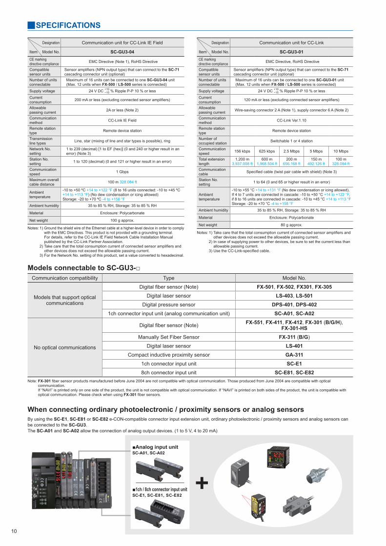
Models connectable to SC-GU3-□
When connecting ordinary photoelectronic / proximity sensors or analog sensorsBy using the SC-E1, SC-E81 or SC-E82 e-CON-compatible connector input extension unit, ordinary photoelectronic / proximity sensors and analog sensors can be connected to the SC-GU3.The SC-A01 and SC-A02 allow the connection of analog output devices. (1 to 5 V, 4 to 20 mA)
Communication compatibility Type Model No.
Models that support optical communications
Digital fiber sensor (Note) FX-501, FX-502, FX301, FX-305Digital laser sensor LS-403, LS-501
Digital pressure sensor DPS-401, DPS-4021ch connector input unit (analog communication unit) SC-A01, SC-A02
No optical communications
Digital fiber sensor (Note) FX-551, FX-411, FX-412, FX-301 (B/G/H), FX-301-HS
Manually Set Fiber Sensor FX-311 (B/G)
Digital laser sensor LS-401Compact inductive proximity sensor GA-311
1ch connector input unit SC-E18ch connector input unit SC-E81, SC-E82
Note: FX-301 fiber sensor products manufactured before June 2004 are not compatible with optical communication. Those produced from June 2004 are compatible with optical communication. If “NAVI” is printed only on one side of the product, the unit is not compatible with optical communication. If “NAVI” is printed on both sides of the product, the unit is compatible with optical communication. Please check when using FX-301 fiber sensors.
Designation Communication unit for CC-Link IE Field
Item Model No. SC-GU3-04CE marking directive compliance EMC Directive (Note 1), RoHS Directive
Compatible sensor units
Sensor amplifiers (NPN output type) that can connect to the SC-71 cascading connector unit (optional)
Number of units connectable
Maximum of 16 units can be connected to one SC-GU3-04 unit(Max. 12 units when FX-500 / LS-500 series is connected)
Supply voltage 24 V DC +10−15 % Ripple P-P 10 % or less
Current consumption 200 mA or less (excluding connected sensor amplifiers)
Allowable passing current 2A or less (Note 2)
Communication method CC-Link IE Field
Remote station type Remote device station
Transmission line types Line, star (mixing of line and star types is possible), ring
Network No. setting
1 to 239 (decimal) [1 to EF (hex)] (0 and 240 or higher result in an error) (Note 3)
Station No. setting 1 to 120 (decimal) (0 and 121 or higher result in an error)
Communication speed 1 Gbps
Maximum overall cable distance 100 m 328.084 ft
Ambient temperature
-10 to +50 ºC +14 to +122 °F (8 to 16 units connected: -10 to +45 ºC +14 to +113 °F) (No dew condensation or icing allowed)Storage: -20 to +70 ºC -4 to +158 °F
Ambient humidity 35 to 85 % RH, Storage: 35 to 85 % RH
Material Enclosure: Polycarbonate
Net weight 100 g approx.
Notes: 1) Ground the shield wire of the Ethernet cable at a higher-level device in order to comply with the EMC Directives. This product is not provided with a grounding terminal. For details, refer to the CC-Link IE Field Network Cable Installation Manual published by the CC-Link Partner Association.
2) Take care that the total consumption current of connected sensor amplifiers and other devices does not exceed the allowable passing current.
3) For the Network No. setting of this product, set a value converted to hexadecimal.
Designation Communication unit for CC-Link
Item Model No. SC-GU3-01CE marking directive compliance EMC Directive, RoHS Directive
Compatible sensor units
Sensor amplifiers (NPN output type) that can connect to the SC-71 cascading connector unit (optional)
Number of units connectable
Maximum of 16 units can be connected to one SC-GU3-01 unit(Max. 12 units when FX-500 / LS-500 series is connected)
Supply voltage 24 V DC +10−15 % Ripple P-P 10 % or less
Current consumption 120 mA or less (excluding connected sensor amplifiers)
Allowable passing current Wire-saving connector 2 A (Note 1), supply connector 6 A (Note 2)
Communication method CC-Link Ver.1.10
Remote station type Remote device station
Number of occupied station Switchable 1 or 4 station
Communication speed 156 kbps 625 kbps 2.5 Mbps 5 Mbps 10 Mbps
Total extension length
1,200 m 3,937.008 ft
600 m 1,968.504 ft
200 m 656.168 ft
150 m 492.126 ft
100 m 328.084 ft
Communication cable Specified cable (twist pair cable with shield) (Note 3)
Station No. setting 1 to 64 (0 and 65 or higher result in an error)
Ambient temperature
-10 to +55 °C +14 to +131 °F (No dew condensation or icing allowed),If 4 to 7 units are connected in cascade: -10 to +50 °C +14 to +122 °F,if 8 to 16 units are connected in cascade: -10 to +45 °C +14 to +113 °FStorage: -20 to +70 °C -4 to +158 °F
Ambient humidity 35 to 85 % RH, Storage: 35 to 85 % RH
Material Enclosure: Polycarbonate
Net weight 80 g approx.
Notes: 1) Take care that the total consumption current of connected sensor amplifiers and other devices does not exceed the allowable passing current.
2) In case of supplying power to other devices, be sure to set the current less than allowable passing current.
3) Use the CC-Link-specified cable.
SPECIFICATIONS
■Analog input unit
■1ch / 8ch connector input unitSC-E1, SC-E81, SC-E82
SC-A01, SC-A02
11
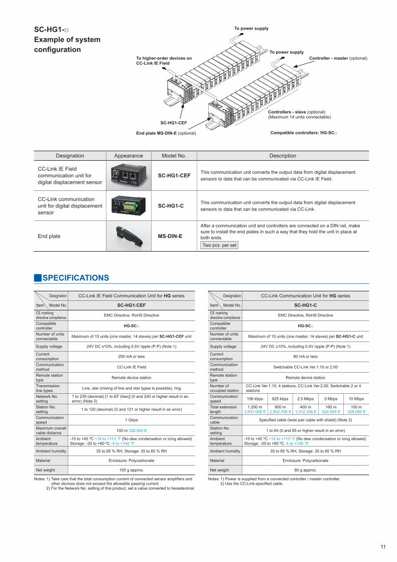
SC-HG1-□Example of system configuration
Designation Appearance Model No. Description
CC-Link IE Field communication unit for digital displacement sensor
SC-HG1-CEF This communication unit converts the output data from digital displacement sensors to data that can be communicated via CC-Link IE Field.
CC-Link communication unit for digital displacement sensor
SC-HG1-C This communication unit converts the output data from digital displacement sensors to data that can be communicated via CC-Link.
End plate MS-DIN-E
After a communication unit and controllers are connected on a DIN rail, make sure to install the end plates in such a way that they hold the unit in place at both ends. Two pcs. per set
To higher-order devices on CC-Link IE Field
End plate MS-DIN-E (optional)
To power supply
To power supply
Controllers - slave (optional)(Maximum 14 units connectable)
Controller - master (optional)
Compatible controllers: HG-SC□
SC-HG1-CEF
Designation CC-Link Communication Unit for HG series
Item Model No. SC-HG1-CCE marking directive compliance EMC Directive, RoHS Directive
Compatible controller HG-SC□
Number of units connectable Maximum of 15 units (one master, 14 slaves) per SC-HG1-C unit
Supply voltage 24V DC ±10%, including 0.5V ripple (P-P) (Note 1)
Current consumption 80 mA or less
Communication method Switchable CC-Link Ver.1.10 or 2.00
Remote station type Remote device station
Number of occupied station
CC-Link Ver.1.10: 4 stations, CC-Link Ver.2.00: Switchable 2 or 4 stations
Communication speed 156 kbps 625 kbps 2.5 Mbps 5 Mbps 10 Mbps
Total extension length
1,200 m 3,937.008 ft
900 m 2,952.756 ft
400 m 1,312.336 ft
160 m 524.934 ft
100 m 328.084 ft
Communication cable Specified cable (twist pair cable with shield) (Note 2)
Station No. setting 1 to 64 (0 and 65 or higher result in an error)
Ambient temperature
-10 to +45 ºC +14 to +113 °F (No dew condensation or icing allowed)Storage: -20 to +60 ºC -4 to +140 °F
Ambient humidity 35 to 85 % RH, Storage: 35 to 85 % RH
Material Enclosure: Polycarbonate
Net weight 80 g approx.
Notes: 1) Power is supplied from a connected controller / master controller. 2) Use the CC-Link-specified cable.
SPECIFICATIONS
Designation CC-Link IE Field Communication Unit for HG series
Item Model No. SC-HG1-CEFCE marking directive compliance EMC Directive, RoHS Directive
Compatible controller HG-SC□
Number of units connectable Maximum of 15 units (one master, 14 slaves) per SC-HG1-CEF unit
Supply voltage 24V DC ±10%, including 0.5V ripple (P-P) (Note 1)
Current consumption 200 mA or less
Communication method CC-Link IE Field
Remote station type Remote device station
Transmission line types Line, star (mixing of line and star types is possible), ring
Network No. setting
1 to 239 (decimal) [1 to EF (hex)] (0 and 240 or higher result in an error) (Note 2)
Station No. setting 1 to 120 (decimal) (0 and 121 or higher result in an error)
Communication speed 1 Gbps
Maximum overall cable distance 100 m 328.084 ft
Ambient temperature
-10 to +45 ºC +14 to +113 °F (No dew condensation or icing allowed)Storage: -20 to +60 ºC -4 to +140 °F
Ambient humidity 35 to 85 % RH, Storage: 35 to 85 % RH
Material Enclosure: Polycarbonate
Net weight 100 g approx.
Notes: 1) Take care that the total consumption current of connected sensor amplifiers and other devices does not exceed the allowable passing current.
2) For the Network No. setting of this product, set a value converted to hexadecimal.
Disclaimer The applications described in the catalog are all intended for examples only. The purchase of our products described in the catalog shall not be regarded as granting of a license to use our products in the described applications. We do NOT warrant that we have obtained some intellectual properties, such as patent rights, with respect to such applications, or that the described applications may not infringe any intellectual property rights, such as patent rights, of a third party.
Please contact:
2431-1 Ushiyama-cho, Kasugai-shi, Aichi, 486-0901, JapanGlobal Sales Department■Telephone: +81-568-33-7861 ■Facsimile: +81-568-33-8591panasonic.net/id/pidsx/global
All Rights Reserved © 2017
Specifications are subject to change without notice. Printed in JapanNo.CE-SCCCLINK-8 June, 2017
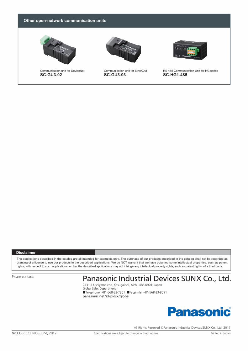
Communication unit for DeviceNetSC-GU3-02
Communication unit for EtherCATSC-GU3-03
RS-485 Communication Unit for HG seriesSC-HG1-485
Other open-network communication units


![新製品ニュース CC-Link IEフィールドネットワーク …...新製品ニュース No.508A [ 2012年12月 ] CC-Link IEフィールドネットワーク 対応製品 ファストロジック機能](https://img.pdfslide.net/doc/110x75/5ecc09a4087ff73ee102b302/efff-cc-link-ieffffffffff-efff.jpg)
![Smart Factory 구현을 위한 자동화 시스템의30C-1].pdf · 보안 강화, 유무선 통합 수집분석, Big Data IT와 융합, IoT ... GOT1000 Series CC-Link / CC-Link IE](https://img.pdfslide.net/doc/110x75/5e0db79fc23ab44abe2d62b8/smart-factory-e-oeoe-e-oeoe-30c-1pdf-e-e.jpg)