Embed Size (px)
Citation preview
White Paper
© 2018 Cisco and/or its affiliates. All rights reserved. This document is Cisco Public Information. Page 1 of 64
Commvault® MediaAgent on Cisco UCS C240 M5 Rack Server
This document provides an introduction to the process of deploying Commvault Data Platform on the Cisco UCS® C240 M5 Rack Server for a traditional Commvault MediaAgent architecture.
February 2018
White Paper
© 2018 Cisco and/or its affiliates. All rights reserved. This document is Cisco Public Information. Page 2 of 64
ContentsIntroduction ........................................................................................................................................................................................3 Technology overview .........................................................................................................................................................................3
Cisco Unified Computing System ...................................................................................................................................................3 Cisco UCS C240 M5 Rack Server .................................................................................................................................................5 Commvault® Data Platform ............................................................................................................................................................5
Commvault® IntelliSnap® technology .........................................................................................................................................7 Solution design and reference architecture configurations ..................................................................................................................7 Reference architecture .......................................................................................................................................................................8
Overview .......................................................................................................................................................................................8 Storage capacity explained .......................................................................................................................................................9
Individual MediaAgent server configurations ...................................................................................................................................9 Cisco UCS C240 M5 configuration .................................................................................................................................................. 11
Standalone configuration with Cisco Integrated Management Controller ...................................................................................... 11 Create virtual disk groups ....................................................................................................................................................... 18
Cisco UCS managed configuration with Cisco UCS Manager ...................................................................................................... 22 Create a suborganization ........................................................................................................................................................ 27 Create the Cisco UCS C240 storage profile ............................................................................................................................ 28 Create disk group policies ....................................................................................................................................................... 28 Create the boot disk group policy ........................................................................................................................................... 28 Create the library disk group policy ........................................................................................................................................ 31 Create the MediaAgent storage profile ................................................................................................................................... 32 Create the Cisco UCS C240 M5 server pool .......................................................................................................................... 35 Create boot policy .................................................................................................................................................................. 37 Create Microsoft Windows 40-Gbps adapter policy ............................................................................................................... 39 Create a vNIC template .......................................................................................................................................................... 41 Create a service profile template ............................................................................................................................................ 42 Create service profiles ............................................................................................................................................................ 51
OS installation for Commvault MediaAgent server ............................................................................................................................ 52 Commvault MediaAgent installation and configuration ...................................................................................................................... 61 For more information ....................................................................................................................................................................... 63
White Paper
© 2018 Cisco and/or its affiliates. All rights reserved. This document is Cisco Public Information. Page 3 of 64
Introduction This document describes at a high level the installation and configuration steps for deploying the Commvault MediaAgent server on the Cisco UCS® C240 M5 Rack Server to build a data protection solution. This document does not provide a detailed step-by-step guide, and not every task is documented. The document focuses on the steps that are relevant to the specific use case under discussion. To complete the deployment, you should be familiar with the following:
● Cisco Unified Computing System™ (Cisco UCS) configuration
● Microsoft Windows installation and configuration
● Commvault® installation and configuration
Technology overview This section introduces the technologies used in the solution described in this document.
Cisco Unified Computing System
Cisco UCS is a state-of-the-art data center platform that unites computing, network, storage access, and virtualization resources into a single cohesive system.
The main components of Cisco UCS are described here:
● Computing: The system is based on an entirely new class of computing system that incorporates rack-mount and blade servers using Intel® Xeon® processor CPUs. The Cisco UCS servers offer the patented Cisco® Extended Memory Technology to support applications with large data sets and allow more virtual machines per server.
● Network: The system is integrated onto a low-latency, lossless, 10- or 40-Gbps unified network fabric. This network foundation consolidates LANs, SANs, and high-performance computing (HPC) networks, which are separate networks today. The unified fabric lowers costs by reducing the number of network adapters, switches, and cables, and by decreasing the power and cooling requirements.
● Virtualization: The system unleashes the full potential of virtualization by enhancing the scalability, performance, and operational control of virtual environments. Cisco security, policy enforcement, and diagnostic features are now extended into virtualized environments to better support changing business and IT requirements.
● Storage access: The system provides consolidated access to both SAN storage and network-attached storage (NAS) over the unified fabric. By unifying the storage access layer, Cisco UCS can access storage over Ethernet (with Network File System [NFS] or Small Computer System Interface over IP [iSCSI]), Fibre Channel, and Fibre Channel over Ethernet (FCoE). This approach provides customers with choice for storage access and investment protection. In addition, server administrators can pre-assign storage-access policies for system connectivity to storage resources, simplifying storage connectivity and management for increased productivity.
White Paper
© 2018 Cisco and/or its affiliates. All rights reserved. This document is Cisco Public Information. Page 4 of 64
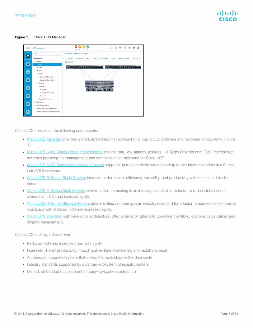
Figure 1. Cisco UCS Manager
Cisco UCS consists of the following components:
● Cisco UCS Manager provides unified, embedded management of all Cisco UCS software and hardware components (Figure 1).
● Cisco UCS 6000 Series Fabric Interconnects are line-rate, low-latency, lossless, 10-Gbps Ethernet and FCoE interconnect switches providing the management and communication backbone for Cisco UCS.
● Cisco UCS 5100 Series Blade Server Chassis supports up to eight blade servers and up to two fabric extenders in a 6-rack
unit (6RU) enclosure.
● Cisco UCS B-Series Blade Servers increase performance, efficiency, versatility, and productivity with Intel-based blade
servers.
● Cisco UCS C-Series Rack Servers deliver unified computing in an industry-standard form factor to reduce total cost of ownership (TCO) and increase agility.
● Cisco UCS S-Series Storage Servers deliver unified computing in an industry-standard form factor to address data-intensive workloads with reduced TCO and increased agility.
● Cisco UCS adapters, with wire-once architecture, offer a range of options to converge the fabric, optimize virtualization, and simplify management.
Cisco UCS is designed to deliver:
● Reduced TCO and increased business agility
● Increased IT staff productivity through just-in-time provisioning and mobility support
● A cohesive, integrated system that unifies the technology in the data center
● Industry standards supported by a partner ecosystem of industry leaders
● Unified, embedded management for easy-to-scale infrastructure
White Paper
© 2018 Cisco and/or its affiliates. All rights reserved. This document is Cisco Public Information. Page 5 of 64
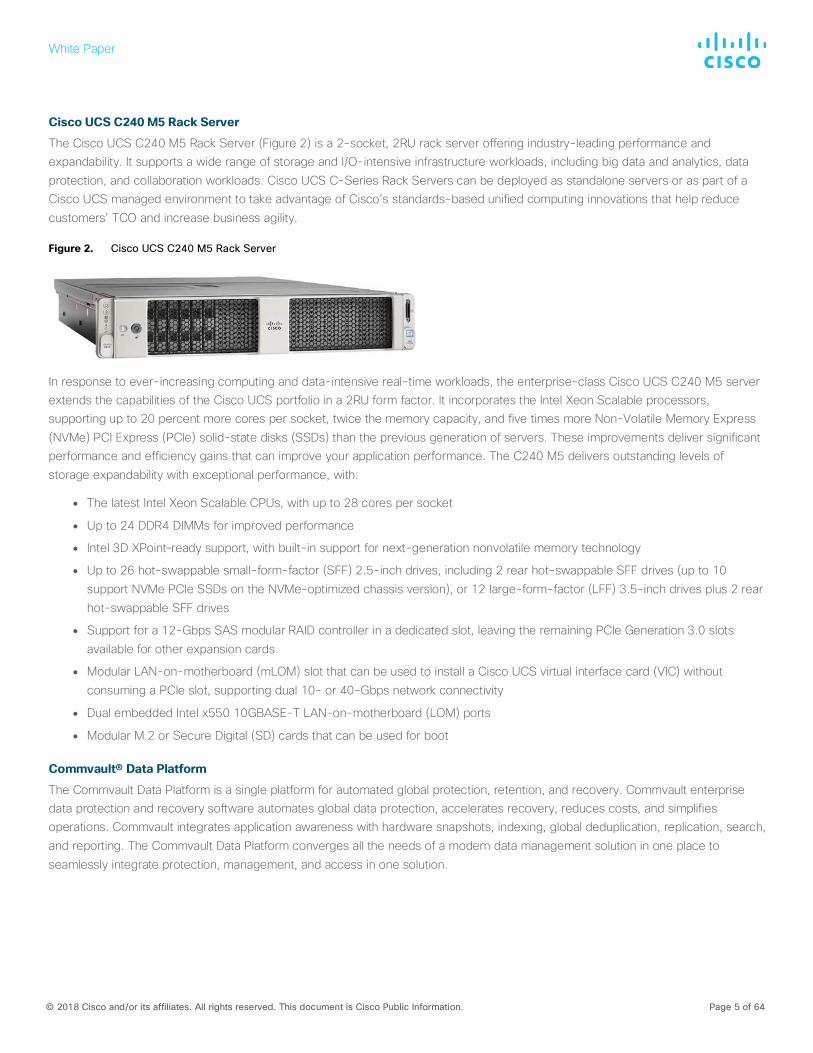
Cisco UCS C240 M5 Rack Server
The Cisco UCS C240 M5 Rack Server (Figure 2) is a 2-socket, 2RU rack server offering industry-leading performance and expandability. It supports a wide range of storage and I/O-intensive infrastructure workloads, including big data and analytics, data protection, and collaboration workloads. Cisco UCS C-Series Rack Servers can be deployed as standalone servers or as part of a Cisco UCS managed environment to take advantage of Cisco’s standards-based unified computing innovations that help reduce customers’ TCO and increase business agility.
Figure 2. Cisco UCS C240 M5 Rack Server
In response to ever-increasing computing and data-intensive real-time workloads, the enterprise-class Cisco UCS C240 M5 server extends the capabilities of the Cisco UCS portfolio in a 2RU form factor. It incorporates the Intel Xeon Scalable processors, supporting up to 20 percent more cores per socket, twice the memory capacity, and five times more Non-Volatile Memory Express (NVMe) PCI Express (PCIe) solid-state disks (SSDs) than the previous generation of servers. These improvements deliver significant performance and efficiency gains that can improve your application performance. The C240 M5 delivers outstanding levels of storage expandability with exceptional performance, with:
● The latest Intel Xeon Scalable CPUs, with up to 28 cores per socket
● Up to 24 DDR4 DIMMs for improved performance
● Intel 3D XPoint–ready support, with built-in support for next-generation nonvolatile memory technology
● Up to 26 hot-swappable small-form-factor (SFF) 2.5-inch drives, including 2 rear hot-swappable SFF drives (up to 10 support NVMe PCIe SSDs on the NVMe-optimized chassis version), or 12 large-form-factor (LFF) 3.5-inch drives plus 2 rear hot-swappable SFF drives
● Support for a 12-Gbps SAS modular RAID controller in a dedicated slot, leaving the remaining PCIe Generation 3.0 slots available for other expansion cards
● Modular LAN-on-motherboard (mLOM) slot that can be used to install a Cisco UCS virtual interface card (VIC) without consuming a PCIe slot, supporting dual 10- or 40-Gbps network connectivity
● Dual embedded Intel x550 10GBASE-T LAN-on-motherboard (LOM) ports
● Modular M.2 or Secure Digital (SD) cards that can be used for boot
Commvault® Data Platform
The Commvault Data Platform is a single platform for automated global protection, retention, and recovery. Commvault enterprise data protection and recovery software automates global data protection, accelerates recovery, reduces costs, and simplifies operations. Commvault integrates application awareness with hardware snapshots, indexing, global deduplication, replication, search, and reporting. The Commvault Data Platform converges all the needs of a modern data management solution in one place to seamlessly integrate protection, management, and access in one solution.
White Paper
© 2018 Cisco and/or its affiliates. All rights reserved. This document is Cisco Public Information. Page 6 of 64
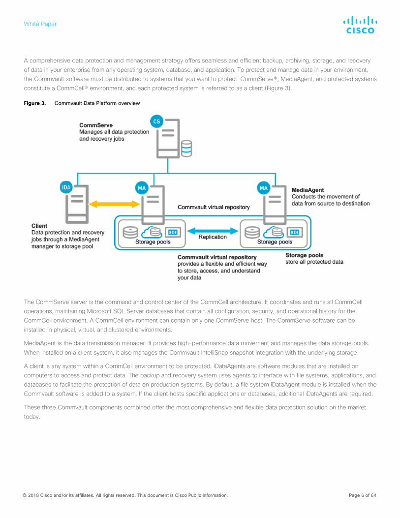
A comprehensive data protection and management strategy offers seamless and efficient backup, archiving, storage, and recovery of data in your enterprise from any operating system, database, and application. To protect and manage data in your environment, the Commvault software must be distributed to systems that you want to protect. CommServe®, MediaAgent, and protected systems constitute a CommCell® environment, and each protected system is referred to as a client (Figure 3).
Figure 3. Commvault Data Platform overview
The CommServe server is the command and control center of the CommCell architecture. It coordinates and runs all CommCell operations, maintaining Microsoft SQL Server databases that contain all configuration, security, and operational history for the CommCell environment. A CommCell environment can contain only one CommServe host. The CommServe software can be installed in physical, virtual, and clustered environments.
MediaAgent is the data transmission manager. It provides high-performance data movement and manages the data storage pools.
When installed on a client system, it also manages the Commvault IntelliSnap snapshot integration with the underlying storage.
A client is any system within a CommCell environment to be protected. iDataAgents are software modules that are installed on computers to access and protect data. The backup and recovery system uses agents to interface with file systems, applications, and databases to facilitate the protection of data on production systems. By default, a file system iDataAgent module is installed when the Commvault software is added to a system. If the client hosts specific applications or databases, additional iDataAgents are required.
These three Commvault components combined offer the most comprehensive and flexible data protection solution on the market today.
White Paper
© 2018 Cisco and/or its affiliates. All rights reserved. This document is Cisco Public Information. Page 7 of 64
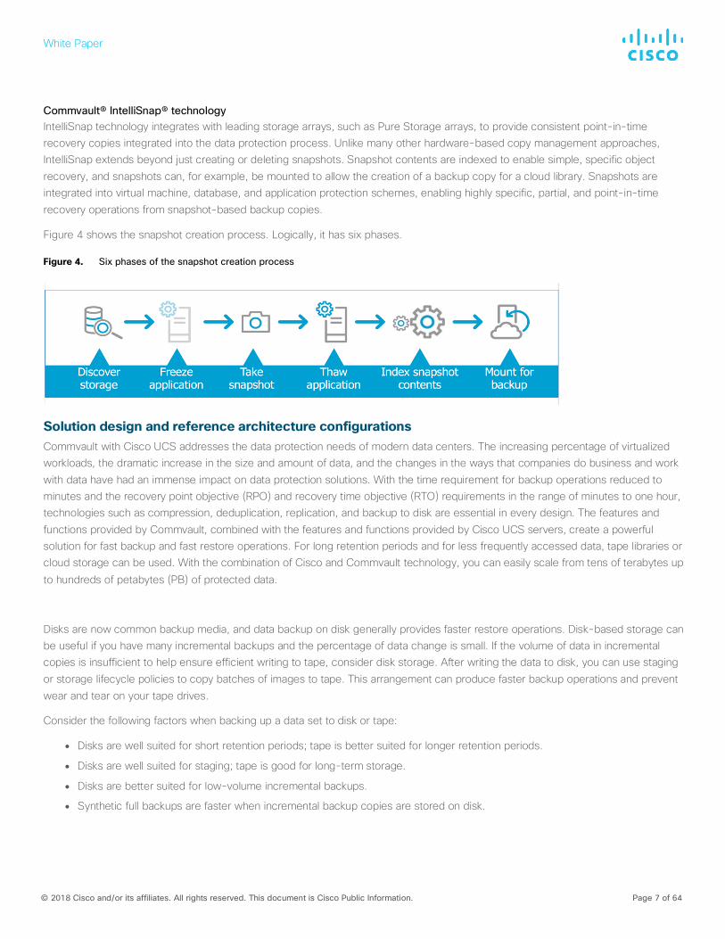
Commvault® IntelliSnap® technology IntelliSnap technology integrates with leading storage arrays, such as Pure Storage arrays, to provide consistent point-in-time recovery copies integrated into the data protection process. Unlike many other hardware-based copy management approaches, IntelliSnap extends beyond just creating or deleting snapshots. Snapshot contents are indexed to enable simple, specific object recovery, and snapshots can, for example, be mounted to allow the creation of a backup copy for a cloud library. Snapshots are integrated into virtual machine, database, and application protection schemes, enabling highly specific, partial, and point-in-time recovery operations from snapshot-based backup copies.
Figure 4 shows the snapshot creation process. Logically, it has six phases.
Figure 4. Six phases of the snapshot creation process
Solution design and reference architecture configurations Commvault with Cisco UCS addresses the data protection needs of modern data centers. The increasing percentage of virtualized workloads, the dramatic increase in the size and amount of data, and the changes in the ways that companies do business and work with data have had an immense impact on data protection solutions. With the time requirement for backup operations reduced to minutes and the recovery point objective (RPO) and recovery time objective (RTO) requirements in the range of minutes to one hour, technologies such as compression, deduplication, replication, and backup to disk are essential in every design. The features and functions provided by Commvault, combined with the features and functions provided by Cisco UCS servers, create a powerful solution for fast backup and fast restore operations. For long retention periods and for less frequently accessed data, tape libraries or cloud storage can be used. With the combination of Cisco and Commvault technology, you can easily scale from tens of terabytes up
to hundreds of petabytes (PB) of protected data.
Disks are now common backup media, and data backup on disk generally provides faster restore operations. Disk-based storage can be useful if you have many incremental backups and the percentage of data change is small. If the volume of data in incremental copies is insufficient to help ensure efficient writing to tape, consider disk storage. After writing the data to disk, you can use staging or storage lifecycle policies to copy batches of images to tape. This arrangement can produce faster backup operations and prevent wear and tear on your tape drives.
Consider the following factors when backing up a data set to disk or tape:
● Disks are well suited for short retention periods; tape is better suited for longer retention periods.
● Disks are well suited for staging; tape is good for long-term storage.
● Disks are better suited for low-volume incremental backups.
● Synthetic full backups are faster when incremental backup copies are stored on disk.
White Paper
© 2018 Cisco and/or its affiliates. All rights reserved. This document is Cisco Public Information. Page 8 of 64
● Restoration from disk is usually faster than from tape.
● If client backup operations are too slow to keep the tape in motion, send the backups to disk.
● If the backups are small, send the backups to disk.
● Staging or lifecycle policies can later move the backup images to tape.
There is no “best” position in the infrastructure to install a Commvault with Cisco UCS solution. Many options are available regardless of how big a data center is. One option is to position the solution in a central place in the physical network so that it can be accessed from everywhere with the required bandwidth. Another option is to place the solution as close as possible to the data source.
With most data transferred from the backup client to the server and not directly from storage, and with the unique design of Cisco UCS, the use of a Cisco UCS domain will limit the network bandwidth required for data replication between the Commvault
MediaAgent nodes. This option also allows Cisco UCS Manager to manage all Commvault MediaAgent servers in a central place.
Reference architecture This section introduces the reference architecture for the Commvault and Cisco solution.
Overview
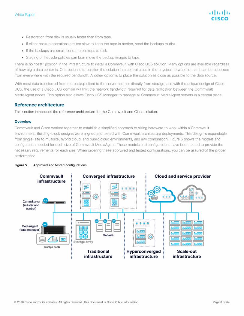
Commvault and Cisco worked together to establish a simplified approach to sizing hardware to work within a Commvault environment. Building-block designs were aligned and tested with Commvault architecture deployments. This design is expandable from single-site to multisite, hybrid cloud, and public cloud environments, and any combination. Figure 5 shows the models and configuration needed for each size of Commvault MediaAgent. These models and configurations have been tested to provide the necessary requirements for each size. When ordering these approved and tested configurations, you can be assured of the proper performance.
Figure 5. Approved and tested configurations
White Paper
© 2018 Cisco and/or its affiliates. All rights reserved. This document is Cisco Public Information. Page 9 of 64
Storage capacity explained Customers sometimes ask why a freshly formatted hard disk or array is smaller than the advertised capacity. For example, a 1-TB drive has 931 GB after formatting.
The reason for this is that hardware and storage manufacturers count the capacity in different ways than the files system does. The prefixes kilo-, mega-, giga-, and tera- are used to state powers of ten. However, in computer software, the data being handled is typically organized based on powers of 2, so it became customary to call 2 x 10 a kilobyte, which is actually 1024 bytes, not exactly
1000 bytes.
There are prefixes to differentiate between base 10 and base 2; however, these are seldom used. In base 2 the proper terms are kibibyte, mebibyte, gibibyte, and tebibyte. The “bi” refers to binary, and the shortened terms are KiB, MiB, GiB, and TiB.
Here’s the underlying math:
● Hard disk manufacturers assume kilo = 103 = 1000 (KB).
● File systems assume kilo = 224 = 1024 (KiB).
To convert KB, MB, and GB to KiB, MiB, and GiB, see the following list:
● KB to KiB: 1000/1024 = 0.9766
● MB to MiB: (1000 x 1000) / (1024 x 1024) = 0.9537
● GB to GiB: (1000 x 1000 x 1000) / (1024 x 1024 x 1024) = 0.9313
● TB to TiB: (1000 x 1000 x 1000 x 1000) / (1024 x 1024 x 1024 x 1024) = 0.9095
Typically, software will display GB or TB as the storage unit, but the amount actually is Gib or TiB, so this confusion will remain unless this approach is changed.
Keep these values in mind as you review the Tables 1 and 2 in the next section. Capacities are stated using the sizes provided by the hardware manufacturer (base 10). Notes reference the software-based sizes (base 2).
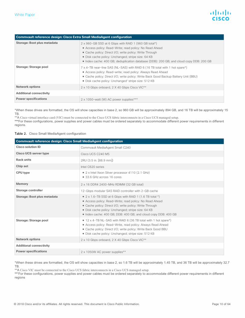
Individual MediaAgent server configurations
Tables 1 and 2 summarize the individual MediaAgent server configurations available. You can choose a configuration based on your data protection requirements. This guide specifically focuses on Cisco UCS C240 as the MediaAgent server and uses a Small server in the example configuration. The storage configuration details depends on the specific customer environment and the size and number of drives available in the Cisco UCS C240 M5 server.
Cisco Extra Small MediaAgent configuration
Commvault reference design: Cisco Extra Small MediaAgent configuration
Cisco solution ID Commvault MediaAgent XS C240
Cisco UCS server type Cisco UCS C240 M5
Rack units 2RU (3.5 in. [88.9 mm])
Chip set Intel C620 series
CPU type 1 x Intel Xeon Silver processor 4110 (2.1 GHz) ● 16.8 GHz across 8 cores
Memory 2 x 8 DDR4 2400-MHz RDIMM (16 GB total)
Storage controller 12-Gbps modular SAS RAID controller with 2-GB cache
White Paper
© 2018 Cisco and/or its affiliates. All rights reserved. This document is Cisco Public Information. Page 10 of 64
Commvault reference design: Cisco Extra Small MediaAgent configuration
Storage: Boot plus metadata 2 x 960-GB SSD at 6 Gbps with RAID 1 (960 GB total*) ● Access policy: Read-Write; read policy: No Read Ahead ● Cache policy: Direct I/O; write policy: Write Through ● Disk cache policy: Unchanged; stripe size: 64 KB ● Index cache: 400 GB; deduplication database (DDB): 200 GB; and cloud copy DDB: 200 GB
Storage: Storage pool 7 x 4-TB near-line SAS (NL-SAS) with RAID 6 (16 TB total with 1 hot spare*) ● Access policy: Read-write; read policy: Always Read Ahead ● Cache policy: Direct I/O; write policy: Write Back Good Backup Battery Unit (BBU) ● Disk cache policy: Unchanged’ stripe size: 512 KB
Network options 2 x 10 Gbps onboard, 2 X 40 Gbps Cisco VIC**
Additional connectivity
Power specifications 2 x 1050-watt (W) AC power supplies***
*When these drives are formatted, the OS will show capacities in base 2, so 960 GB will be approximately 894 GB, and 16 TB will be approximately 15 TB. **A Cisco virtual interface card (VIC) must be connected to the Cisco UCS fabric interconnects in a Cisco UCS managed setup. ***For these configurations, power supplies and power cables must be ordered separately to accommodate different power requirements in different regions.
Cisco Small MediaAgent configuration
Commvault reference design: Cisco Small MediaAgent configuration
Cisco solution ID Commvault MediaAgent Small C240
Cisco UCS server type Cisco UCS C240 M5
Rack units 2RU (3.5 in. [88.9 mm])
Chip set Intel C620 series
CPU type ● 2 x Intel Xeon Silver processor 4110 (2.1 GHz) ● 33.6 GHz across 16 cores
Memory 2 x 16 DDR4 2400-MHz RDIMM (32 GB total)
Storage controller 12-Gbps modular SAS RAID controller with 2-GB cache
Storage: Boot plus metadata ● 2 x 1.6-TB SSD at 6 Gbps with RAID 1 (1.6 TB total *) ● Access policy: Read-Write; read policy: No Read Ahead ● Cache policy: Direct I/O; write policy: Write Through ● Disk cache policy: Unchanged; stripe size: 64 KB ● Index cache: 400 GB; DDB: 400 GB; and cloud copy DDB: 400 GB
Storage: Storage pool ● 12 x 4-TB NL-SAS with RAID 6 (36 TB total with 1 hot spare*) ● Access policy: Read-Write, read policy: Always Read Ahead ● Cache policy: Direct I/O; write policy: Write Back Good BBU ● Disk cache policy: Unchanged; stripe size: 512 KB
Network options 2 x 10 Gbps onboard, 2 X 40 Gbps Cisco VIC**
Additional connectivity
Power specifications 2 x 1050W AC power supplies**
*When these drives are formatted, the OS will show capacities in base 2, so 1.6 TB will be approximately 1.45 TB, and 36 TB will be approximately 32.7 TB. **A Cisco VIC must be connected to the Cisco UCS fabric interconnects in a Cisco UCS managed setup. ***For these configurations, power supplies and power cables must be ordered separately to accommodate different power requirements in different regions
White Paper
© 2018 Cisco and/or its affiliates. All rights reserved. This document is Cisco Public Information. Page 11 of 64
Cisco UCS C240 M5 configuration This document discusses the use of a standalone Cisco UCS C240 M5 Server as well as the use of a Cisco UCS C240 M5 Server managed by Cisco UCS to install Commvault MediaAgent server with a media management role.
Please use the Cisco UCS C240 M5 installation guide to complete the initial configuration (IP addresses, passwords, software versions, etc.). This document assumes that the C240 is accessible through the Cisco Integrated Management Controller (IMC) or
Cisco UCS Manager over the network.
Standalone configuration with Cisco Integrated Management Controller
Follow these steps to configure a standalone solution using IMC.
1. Log on to the IMC as the admin user.
White Paper
© 2018 Cisco and/or its affiliates. All rights reserved. This document is Cisco Public Information. Page 12 of 64
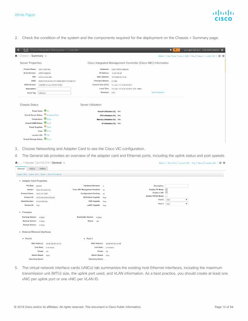
2. Check the condition of the system and the components required for the deployment on the Chassis > Summary page.
3. Choose Networking and Adapter Card to see the Cisco VIC configuration.
4. The General tab provides an overview of the adapter card and Ethernet ports, including the uplink status and port speeds.
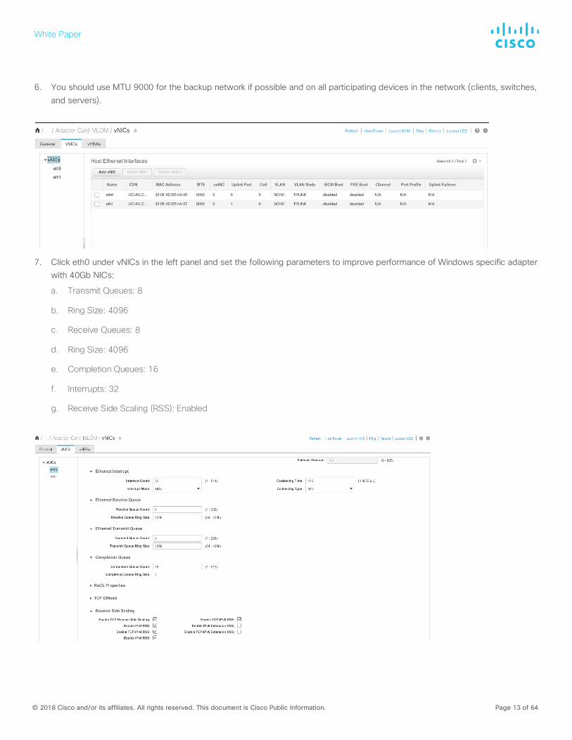
5. The virtual network interface cards (vNICs) tab summarizes the existing host Ethernet interfaces, including the maximum transmission unit (MTU) size, the uplink port used, and VLAN information. As a best practice, you should create at least one vNIC per uplink port or one vNIC per VLAN ID.
White Paper
© 2018 Cisco and/or its affiliates. All rights reserved. This document is Cisco Public Information. Page 13 of 64
6. You should use MTU 9000 for the backup network if possible and on all participating devices in the network (clients, switches, and servers).
7. Click eth0 under vNICs in the left panel and set the following parameters to improve performance of Windows specific adapter with 40Gb NICs:
a. Transmit Queues: 8
b. Ring Size: 4096
c. Receive Queues: 8
d. Ring Size: 4096
e. Completion Queues: 16
f. Interrupts: 32
g. Receive Side Scaling (RSS): Enabled
White Paper
© 2018 Cisco and/or its affiliates. All rights reserved. This document is Cisco Public Information. Page 14 of 64
8. Click Save Changes.
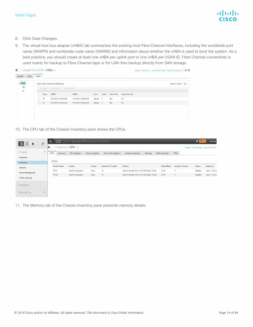
9. The virtual host bus adapter (vHBA) tab summarizes the existing host Fibre Channel Interfaces, including the worldwide port name (WWPN) and worldwide node name (WWNN) and information about whether the vHBA is used to boot the system. As a best practice, you should create at least one vHBA per uplink port or one vHBA per VSAN ID. Fibre Channel connectivity is used mainly for backup to Fibre Channel tape or for LAN-free backup directly from SAN storage.
10. The CPU tab of the Chassis Inventory pane shows the CPUs.
11. The Memory tab of the Chassis Inventory pane presents memory details.
White Paper
© 2018 Cisco and/or its affiliates. All rights reserved. This document is Cisco Public Information. Page 15 of 64
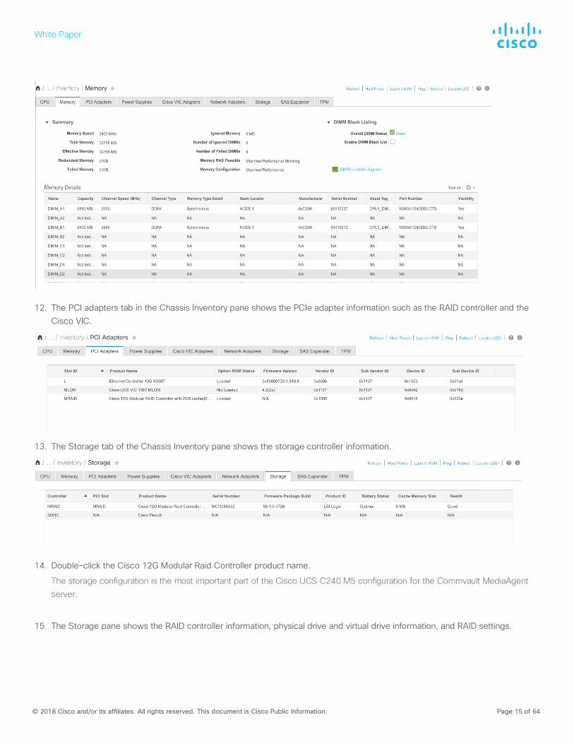
12. The PCI adapters tab in the Chassis Inventory pane shows the PCIe adapter information such as the RAID controller and the Cisco VIC.
13. The Storage tab of the Chassis Inventory pane shows the storage controller information.
14. Double-click the Cisco 12G Modular Raid Controller product name.
The storage configuration is the most important part of the Cisco UCS C240 M5 configuration for the Commvault MediaAgent server.
15. The Storage pane shows the RAID controller information, physical drive and virtual drive information, and RAID settings.
White Paper
© 2018 Cisco and/or its affiliates. All rights reserved. This document is Cisco Public Information. Page 16 of 64
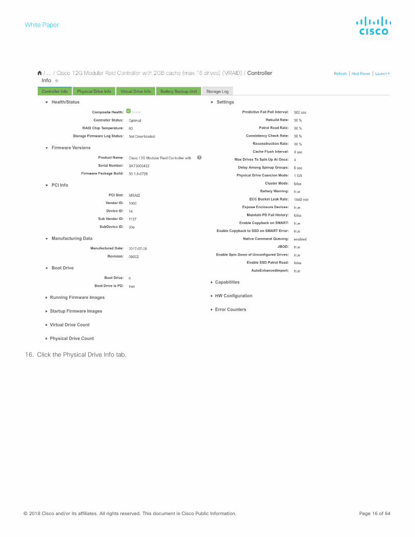
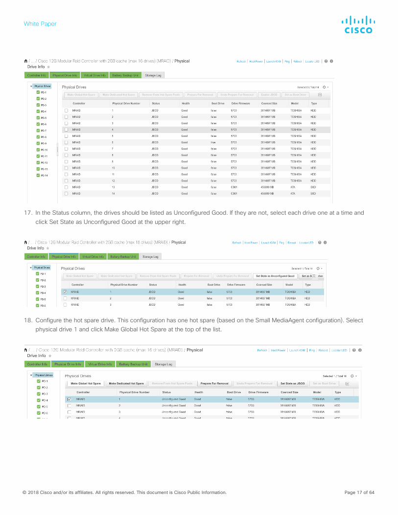
16. Click the Physical Drive Info tab.
White Paper
© 2018 Cisco and/or its affiliates. All rights reserved. This document is Cisco Public Information. Page 17 of 64
17. In the Status column, the drives should be listed as Unconfigured Good. If they are not, select each drive one at a time and click Set State as Unconfigured Good at the upper right.
18. Configure the hot spare drive. This configuration has one hot spare (based on the Small MediaAgent configuration). Select physical drive 1 and click Make Global Hot Spare at the top of the list.
White Paper
© 2018 Cisco and/or its affiliates. All rights reserved. This document is Cisco Public Information. Page 18 of 64
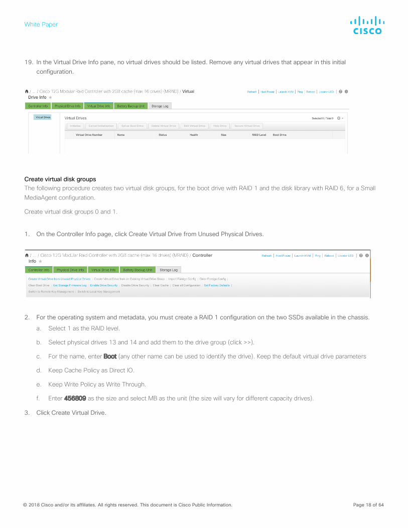
19. In the Virtual Drive Info pane, no virtual drives should be listed. Remove any virtual drives that appear in this initial configuration.
Create virtual disk groups The following procedure creates two virtual disk groups, for the boot drive with RAID 1 and the disk library with RAID 6, for a Small MediaAgent configuration.
Create virtual disk groups 0 and 1.
1. On the Controller Info page, click Create Virtual Drive from Unused Physical Drives.
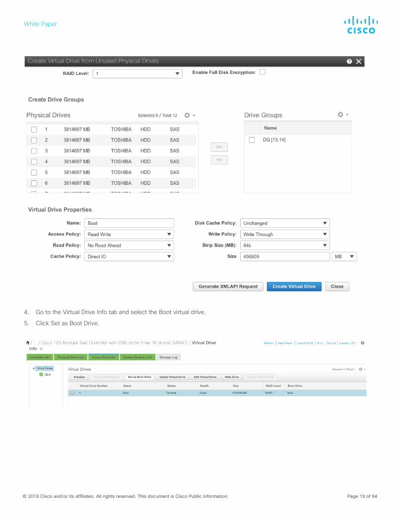
2. For the operating system and metadata, you must create a RAID 1 configuration on the two SSDs available in the chassis.
a. Select 1 as the RAID level.
b. Select physical drives 13 and 14 and add them to the drive group (click >>).
c. For the name, enter Boot (any other name can be used to identify the drive). Keep the default virtual drive parameters
d. Keep Cache Policy as Direct IO.
e. Keep Write Policy as Write Through.
f. Enter 456809 as the size and select MB as the unit (the size will vary for different capacity drives).
3. Click Create Virtual Drive.
White Paper
© 2018 Cisco and/or its affiliates. All rights reserved. This document is Cisco Public Information. Page 19 of 64
4. Go to the Virtual Drive Info tab and select the Boot virtual drive.
5. Click Set as Boot Drive.
White Paper
© 2018 Cisco and/or its affiliates. All rights reserved. This document is Cisco Public Information. Page 20 of 64
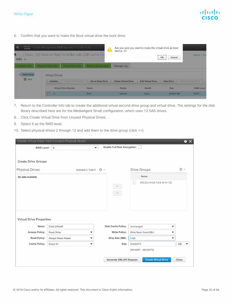
6. Confirm that you want to make the Boot virtual drive the boot drive.
7. Return to the Controller Info tab to create the additional virtual second drive group and virtual drive. The settings for the disk library described here are for the MediaAgent Small configuration, which uses 12 SAS drives.
8. Click Create Virtual Drive from Unused Physical Drives.
9. Select 6 as the RAID level.
10. Select physical drives 2 through 12 and add them to the drive group (click >>).
White Paper
© 2018 Cisco and/or its affiliates. All rights reserved. This document is Cisco Public Information. Page 21 of 64
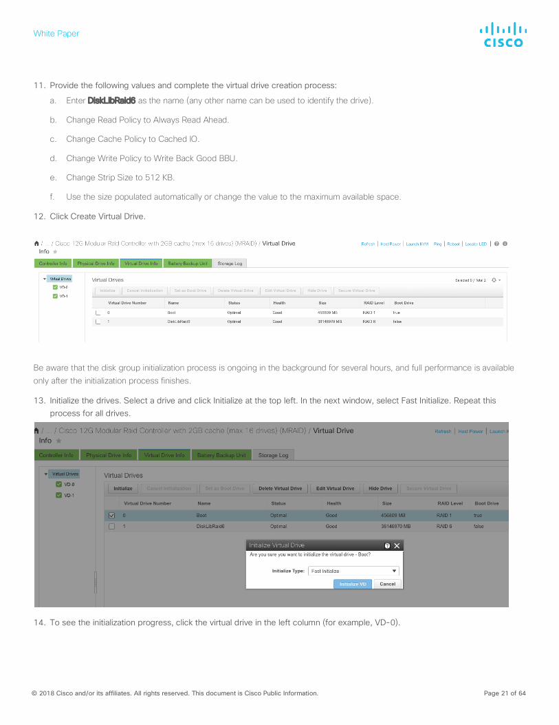
11. Provide the following values and complete the virtual drive creation process:
a. Enter DiskLibRaid6 as the name (any other name can be used to identify the drive).
b. Change Read Policy to Always Read Ahead.
c. Change Cache Policy to Cached IO.
d. Change Write Policy to Write Back Good BBU.
e. Change Strip Size to 512 KB.
f. Use the size populated automatically or change the value to the maximum available space.
12. Click Create Virtual Drive.
Be aware that the disk group initialization process is ongoing in the background for several hours, and full performance is available only after the initialization process finishes.
13. Initialize the drives. Select a drive and click Initialize at the top left. In the next window, select Fast Initialize. Repeat this process for all drives.
14. To see the initialization progress, click the virtual drive in the left column (for example, VD-0).
White Paper
© 2018 Cisco and/or its affiliates. All rights reserved. This document is Cisco Public Information. Page 22 of 64
15. The server is now ready to load the OS.
Note: The number and size of drives dictate the virtual drive configuration. The values are based on the suggested MediaAgent
configuration detailed earlier in this document.
Cisco UCS managed configuration with Cisco UCS Manager
The following section covers the configuration of Cisco UCS managed Cisco C240 M5 servers.
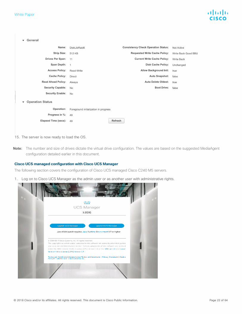
1. Log on to Cisco UCS Manager as the admin user or as another user with administrative rights.
White Paper
© 2018 Cisco and/or its affiliates. All rights reserved. This document is Cisco Public Information. Page 23 of 64
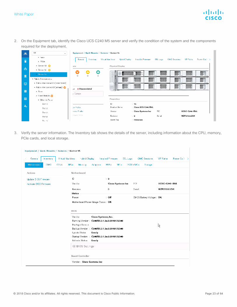
2. On the Equipment tab, identify the Cisco UCS C240 M5 server and verify the condition of the system and the components required for the deployment.
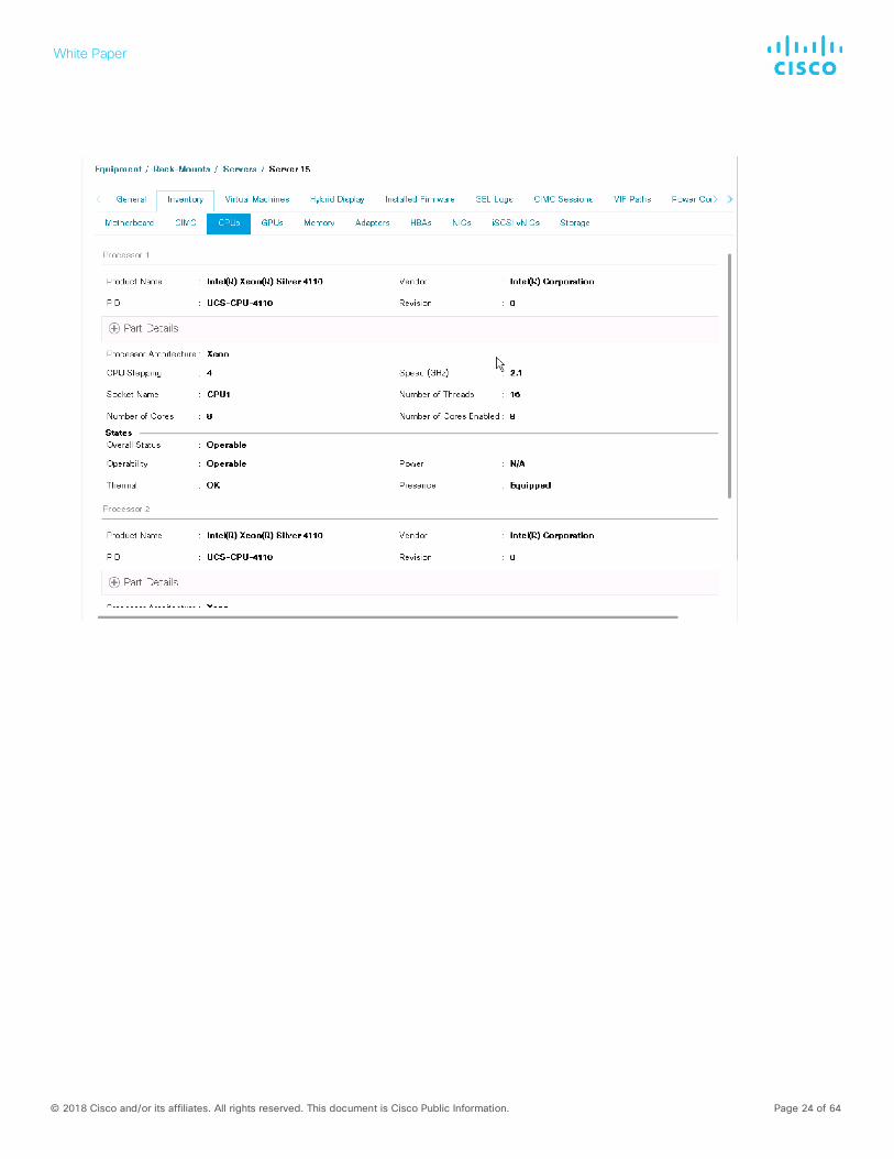
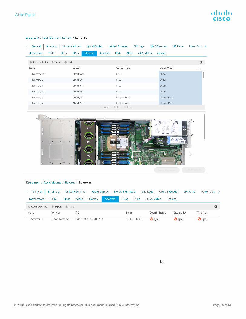
3. Verify the server information. The Inventory tab shows the details of the server, including information about the CPU, memory, PCIe cards, and local storage.
White Paper
© 2018 Cisco and/or its affiliates. All rights reserved. This document is Cisco Public Information. Page 24 of 64
White Paper
© 2018 Cisco and/or its affiliates. All rights reserved. This document is Cisco Public Information. Page 25 of 64
White Paper
© 2018 Cisco and/or its affiliates. All rights reserved. This document is Cisco Public Information. Page 26 of 64
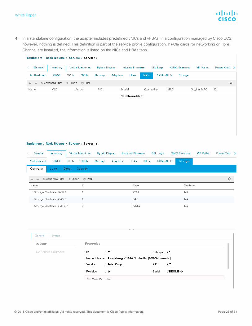
4. In a standalone configuration, the adapter includes predefined vNICs and vHBAs. In a configuration managed by Cisco UCS, however, nothing is defined. This definition is part of the service profile configuration. If PCIe cards for networking or Fibre Channel are installed, the information is listed on the NICs and HBAs tabs.
White Paper
© 2018 Cisco and/or its affiliates. All rights reserved. This document is Cisco Public Information. Page 27 of 64
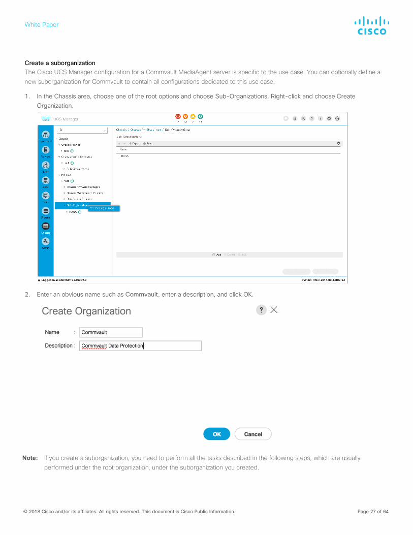
Create a suborganization The Cisco UCS Manager configuration for a Commvault MediaAgent server is specific to the use case. You can optionally define a new suborganization for Commvault to contain all configurations dedicated to this use case.
1. In the Chassis area, choose one of the root options and choose Sub-Organizations. Right-click and choose Create Organization.
2. Enter an obvious name such as Commvault, enter a description, and click OK.
Note: If you create a suborganization, you need to perform all the tasks described in the following steps, which are usually performed under the root organization, under the suborganization you created.
White Paper
© 2018 Cisco and/or its affiliates. All rights reserved. This document is Cisco Public Information. Page 28 of 64
The next steps are dependent on the available disk drives C240 M5 Commvault MediaAgent server. To complete the storage configuration discussed earlier in this document, you need to identify the physical disks available for the operating system installation
and disk library.
For a configuration with 12 disk drives for disk library, use the steps in the following sections.
Create the Cisco UCS C240 storage profile The Cisco UCS C240 rack server will use a storage profile like the Cisco UCS S3260 Storage Server, but it will not need a controller definition, because the C240 in this environment has all disks in front-facing drive slots. You need to create two disk policies for local logical unit numbers (LUNs) to use as the boot device and the disk library for MediaAgent, and you can create others if additional local LUNs are needed.
The storage profile consists of storage polices used for creating local LUNs from the allocated disks (disk group policies).
Create disk group policies You need to create two disk group policies for the MediaAgent deployment on the Cisco UCS C240 M5 based on the Small MediaAgent configuration options:
● Boot_SSD1: Boot plus metadata LUN for the SSD drives in a RAID 1 configuration
● C240-Disk_Lib: Disk library for MediaAgent using 12 HDDs with RAID 6 with 1 hot spare
Each of these disk group polices will create local LUNs for the C240 server, using available disks of specific types or manual slot
specifications.
Create the boot disk group policy To create the Boot_SSD1 disk group policy, perform the following steps:
1. In Cisco UCS Manager, click Storage in the navigation pane and choose Storage Policies from the Storage pull-down menu options.
2. Right-click and choose Create Disk Group Policy.
3. Do the following:
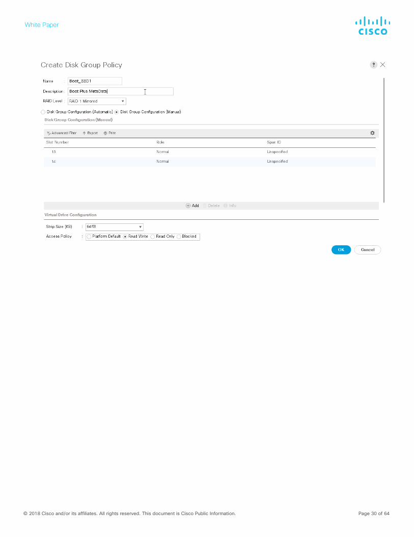
a. Enter an appropriate name (Boot_SSD1).
b. Select RAID 1 Mirrored.
c. Select Disk Group Configuration (Manual).
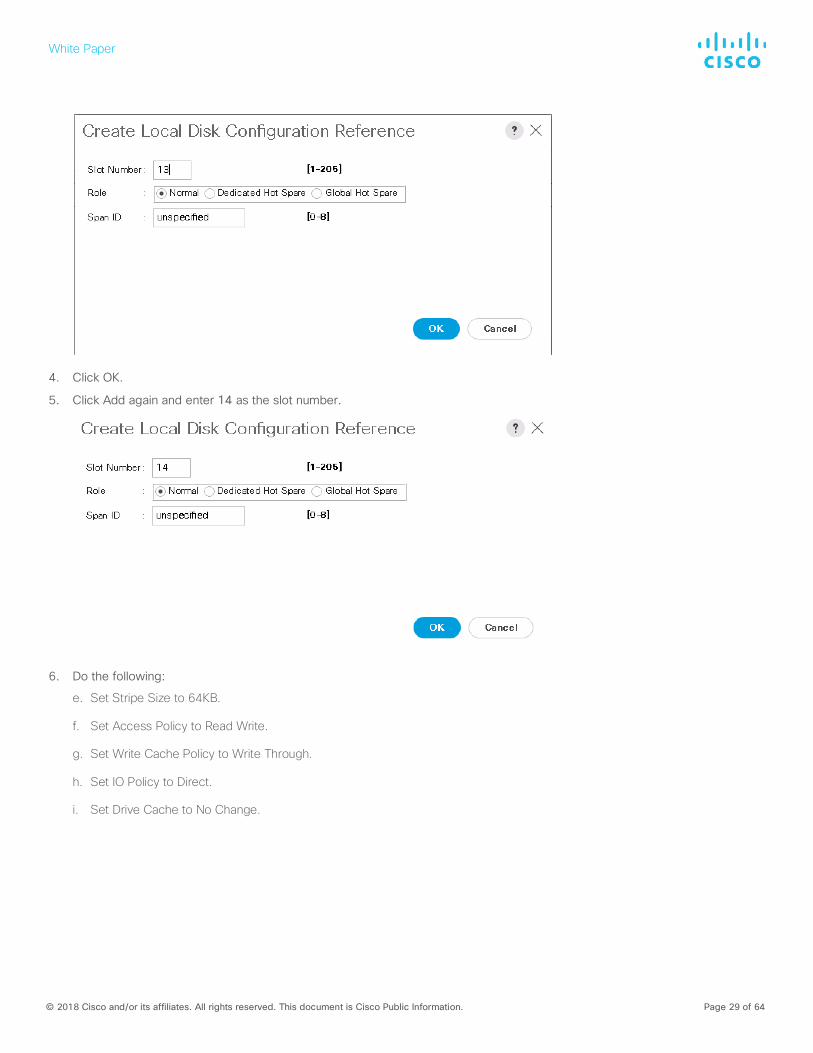
d. Click Add and enter 13 as the slot number.
White Paper
© 2018 Cisco and/or its affiliates. All rights reserved. This document is Cisco Public Information. Page 29 of 64
4. Click OK.
5. Click Add again and enter 14 as the slot number.
6. Do the following:
e. Set Stripe Size to 64KB.
f. Set Access Policy to Read Write.
g. Set Write Cache Policy to Write Through.
h. Set IO Policy to Direct.
i. Set Drive Cache to No Change.
White Paper
© 2018 Cisco and/or its affiliates. All rights reserved. This document is Cisco Public Information. Page 30 of 64
White Paper
© 2018 Cisco and/or its affiliates. All rights reserved. This document is Cisco Public Information. Page 31 of 64
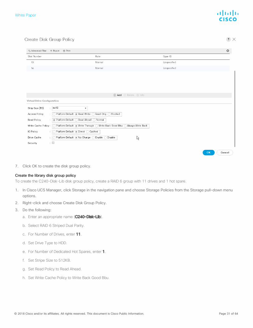
7. Click OK to create the disk group policy.
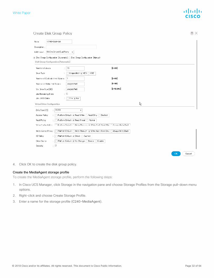
Create the library disk group policy To create the C240-Disk-Lib disk group policy, create a RAID 6 group with 11 drives and 1 hot spare.
1. In Cisco UCS Manager, click Storage in the navigation pane and choose Storage Policies from the Storage pull-down menu options.
2. Right-click and choose Create Disk Group Policy.
3. Do the following:
a. Enter an appropriate name (C240-Disk-Lib).
b. Select RAID 6 Striped Dual Parity.
c. For Number of Drives, enter 11.
d. Set Drive Type to HDD.
e. For Number of Dedicated Hot Spares, enter 1.
f. Set Stripe Size to 512KB.
g. Set Read Policy to Read Ahead.
h. Set Write Cache Policy to Write Back Good Bbu.
White Paper
© 2018 Cisco and/or its affiliates. All rights reserved. This document is Cisco Public Information. Page 32 of 64
4. Click OK to create the disk group policy.
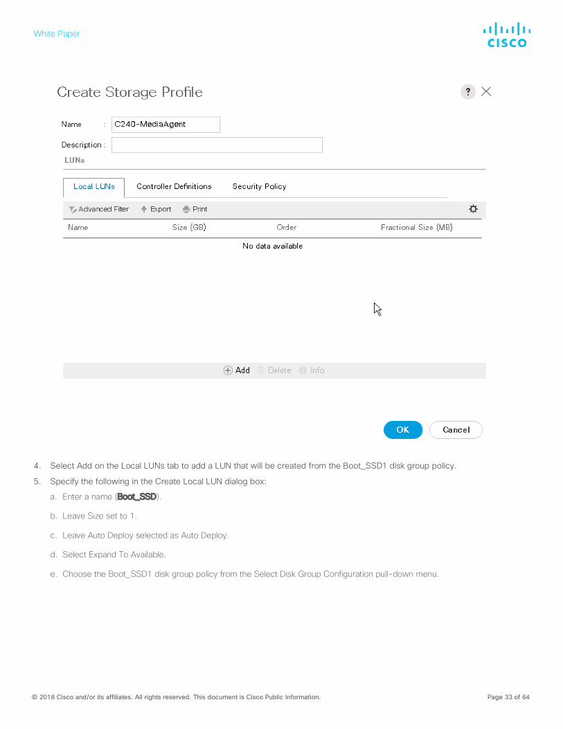
Create the MediaAgent storage profile To create the MediaAgent storage profile, perform the following steps:
1. In Cisco UCS Manager, click Storage in the navigation pane and choose Storage Profiles from the Storage pull-down menu options.
2. Right-click and choose Create Storage Profile.
3. Enter a name for the storage profile (C240-MediaAgent).
White Paper
© 2018 Cisco and/or its affiliates. All rights reserved. This document is Cisco Public Information. Page 33 of 64
4. Select Add on the Local LUNs tab to add a LUN that will be created from the Boot_SSD1 disk group policy.
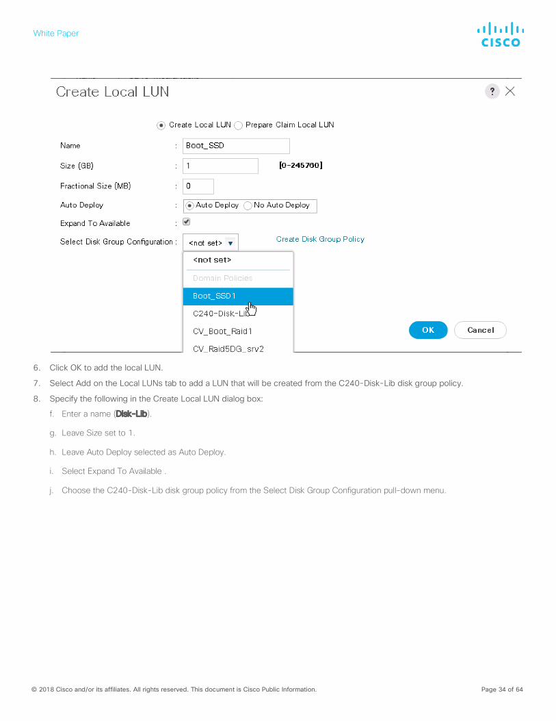
5. Specify the following in the Create Local LUN dialog box:
a. Enter a name (Boot_SSD).
b. Leave Size set to 1.
c. Leave Auto Deploy selected as Auto Deploy.
d. Select Expand To Available.
e. Choose the Boot_SSD1 disk group policy from the Select Disk Group Configuration pull-down menu.
White Paper
© 2018 Cisco and/or its affiliates. All rights reserved. This document is Cisco Public Information. Page 34 of 64
6. Click OK to add the local LUN.
7. Select Add on the Local LUNs tab to add a LUN that will be created from the C240-Disk-Lib disk group policy.
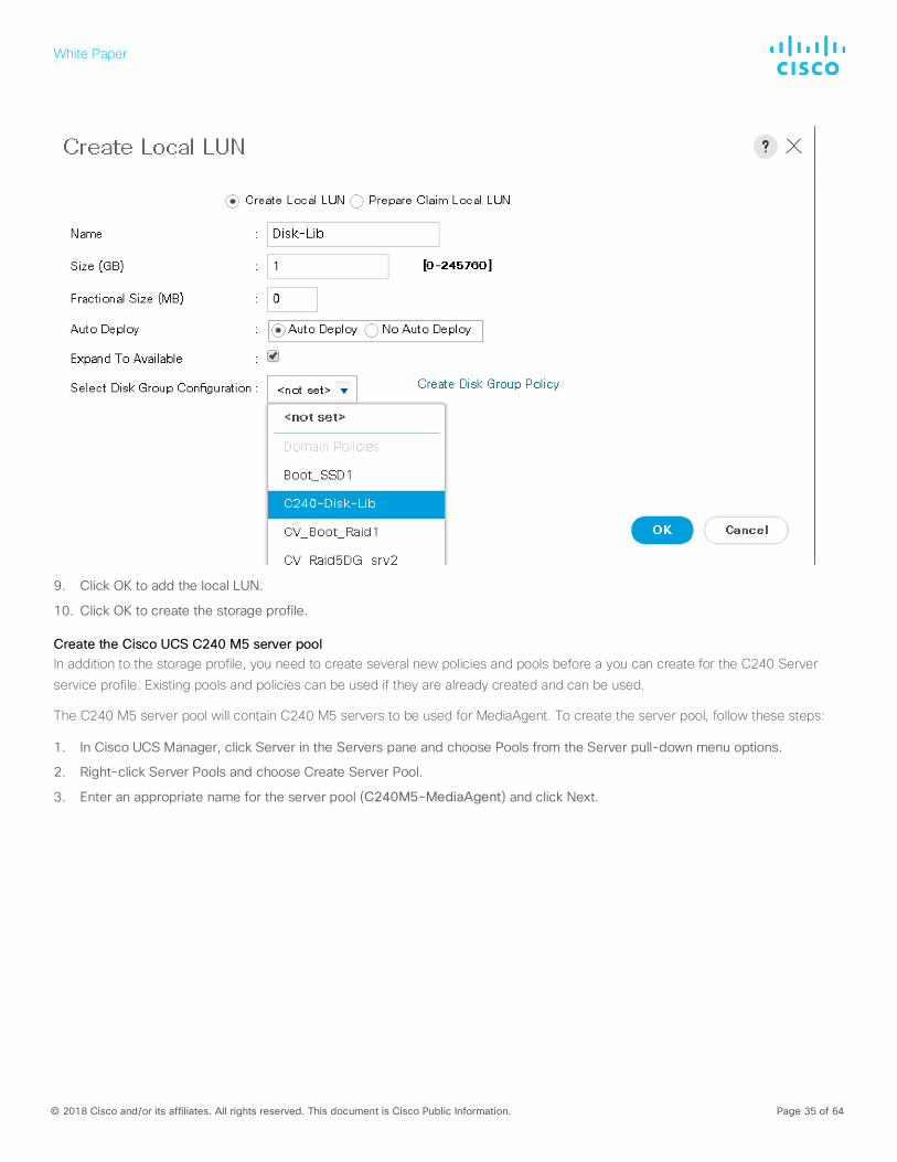
8. Specify the following in the Create Local LUN dialog box:
f. Enter a name (Disk-Lib).
g. Leave Size set to 1.
h. Leave Auto Deploy selected as Auto Deploy.
i. Select Expand To Available .
j. Choose the C240-Disk-Lib disk group policy from the Select Disk Group Configuration pull-down menu.
White Paper
© 2018 Cisco and/or its affiliates. All rights reserved. This document is Cisco Public Information. Page 35 of 64
9. Click OK to add the local LUN.
10. Click OK to create the storage profile.
Create the Cisco UCS C240 M5 server pool In addition to the storage profile, you need to create several new policies and pools before a you can create for the C240 Server
service profile. Existing pools and policies can be used if they are already created and can be used.
The C240 M5 server pool will contain C240 M5 servers to be used for MediaAgent. To create the server pool, follow these steps:
1. In Cisco UCS Manager, click Server in the Servers pane and choose Pools from the Server pull-down menu options.
2. Right-click Server Pools and choose Create Server Pool.
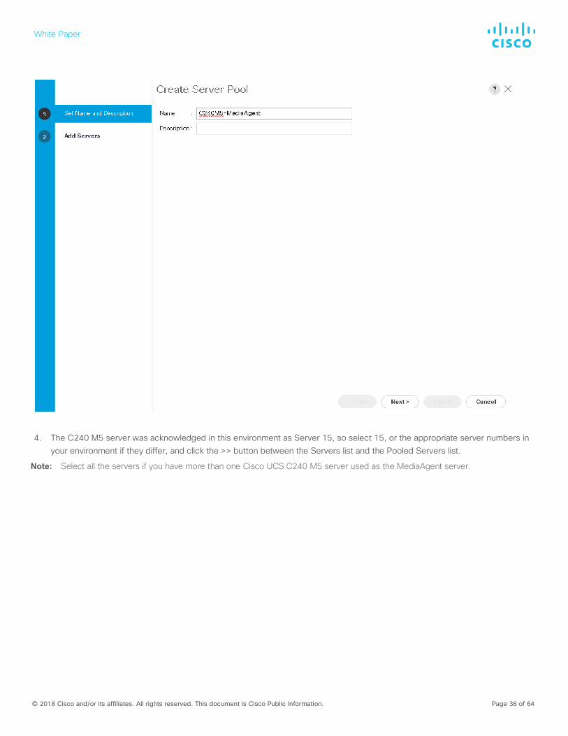
3. Enter an appropriate name for the server pool (C240M5-MediaAgent) and click Next.
White Paper
© 2018 Cisco and/or its affiliates. All rights reserved. This document is Cisco Public Information. Page 36 of 64
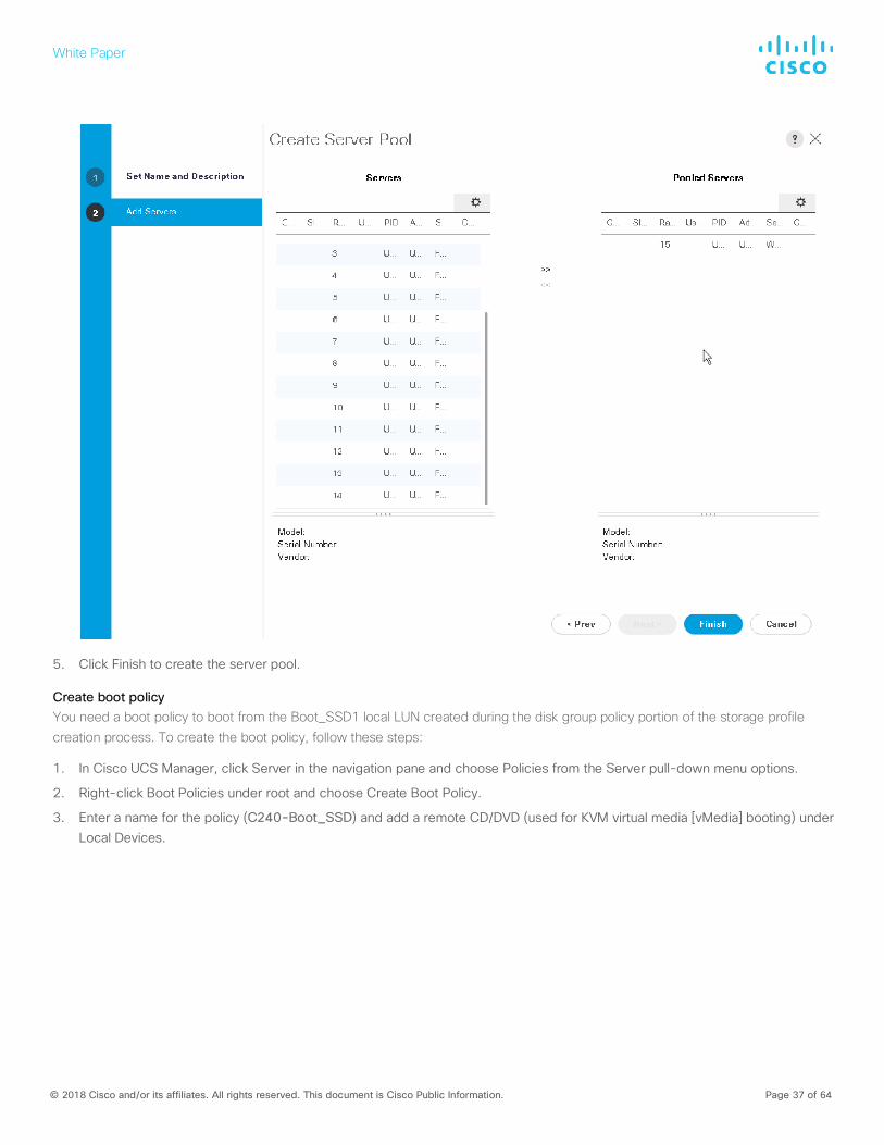
4. The C240 M5 server was acknowledged in this environment as Server 15, so select 15, or the appropriate server numbers in your environment if they differ, and click the >> button between the Servers list and the Pooled Servers list.
Note: Select all the servers if you have more than one Cisco UCS C240 M5 server used as the MediaAgent server.
White Paper
© 2018 Cisco and/or its affiliates. All rights reserved. This document is Cisco Public Information. Page 37 of 64
5. Click Finish to create the server pool.
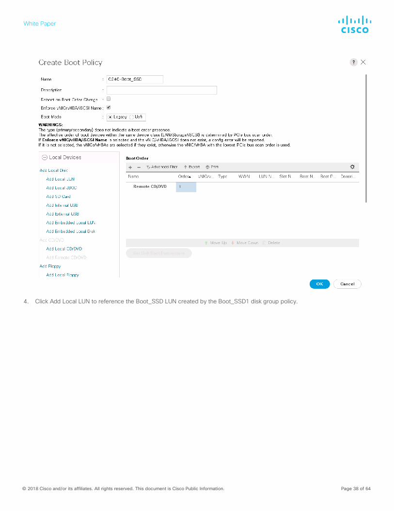
Create boot policy You need a boot policy to boot from the Boot_SSD1 local LUN created during the disk group policy portion of the storage profile creation process. To create the boot policy, follow these steps:
1. In Cisco UCS Manager, click Server in the navigation pane and choose Policies from the Server pull-down menu options.
2. Right-click Boot Policies under root and choose Create Boot Policy.
3. Enter a name for the policy (C240-Boot_SSD) and add a remote CD/DVD (used for KVM virtual media [vMedia] booting) under Local Devices.
White Paper
© 2018 Cisco and/or its affiliates. All rights reserved. This document is Cisco Public Information. Page 38 of 64
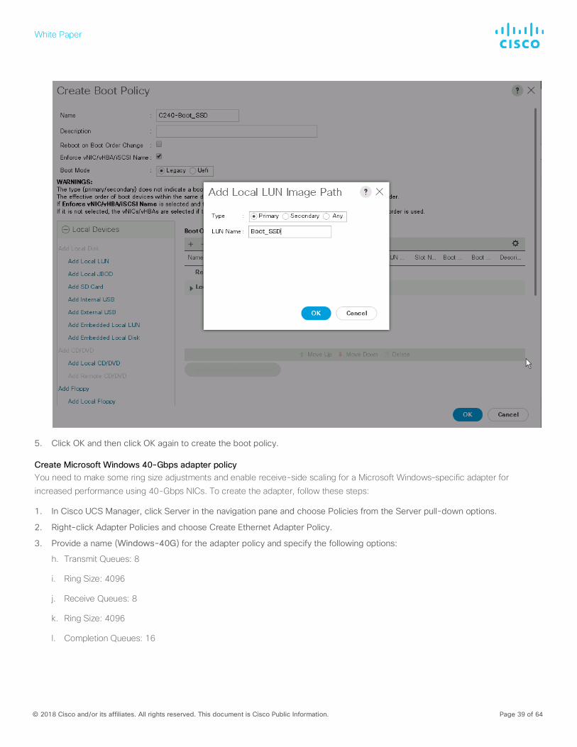
4. Click Add Local LUN to reference the Boot_SSD LUN created by the Boot_SSD1 disk group policy.
White Paper
© 2018 Cisco and/or its affiliates. All rights reserved. This document is Cisco Public Information. Page 39 of 64
5. Click OK and then click OK again to create the boot policy.
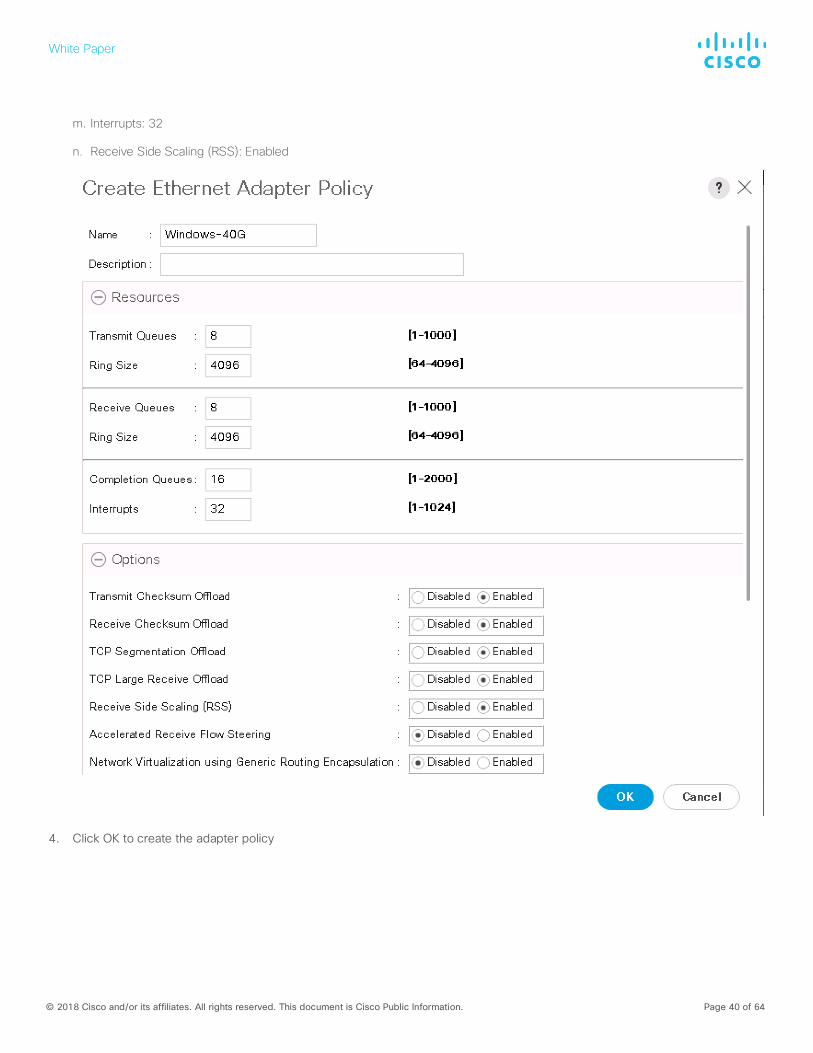
Create Microsoft Windows 40-Gbps adapter policy You need to make some ring size adjustments and enable receive-side scaling for a Microsoft Windows–specific adapter for
increased performance using 40-Gbps NICs. To create the adapter, follow these steps:
1. In Cisco UCS Manager, click Server in the navigation pane and choose Policies from the Server pull-down options.
2. Right-click Adapter Policies and choose Create Ethernet Adapter Policy.
3. Provide a name (Windows-40G) for the adapter policy and specify the following options:
h. Transmit Queues: 8
i. Ring Size: 4096
j. Receive Queues: 8
k. Ring Size: 4096
l. Completion Queues: 16
White Paper
© 2018 Cisco and/or its affiliates. All rights reserved. This document is Cisco Public Information. Page 40 of 64
m. Interrupts: 32
n. Receive Side Scaling (RSS): Enabled
4. Click OK to create the adapter policy
White Paper
© 2018 Cisco and/or its affiliates. All rights reserved. This document is Cisco Public Information. Page 41 of 64
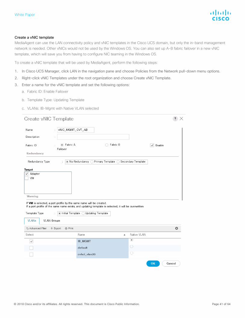
Create a vNIC template MediaAgent can use the LAN connectivity policy and vNIC templates in the Cisco UCS domain, but only the in-band management network is needed. Other vNICs would not be used by the Windows OS. You can also set up A-B fabric failover in a new vNIC template, which will save you from having to configure NIC teaming in the Windows OS.
To create a vNIC template that will be used by MediaAgent, perform the following steps:
1. In Cisco UCS Manager, click LAN in the navigation pane and choose Policies from the Network pull-down menu options.
2. Right-click vNIC Templates under the root organization and choose Create vNIC Template.
3. Enter a name for the vNIC template and set the following options:
a. Fabric ID: Enable Failover
b. Template Type: Updating Template
c. VLANs: IB-Mgmt with Native VLAN selected
White Paper
© 2018 Cisco and/or its affiliates. All rights reserved. This document is Cisco Public Information. Page 42 of 64
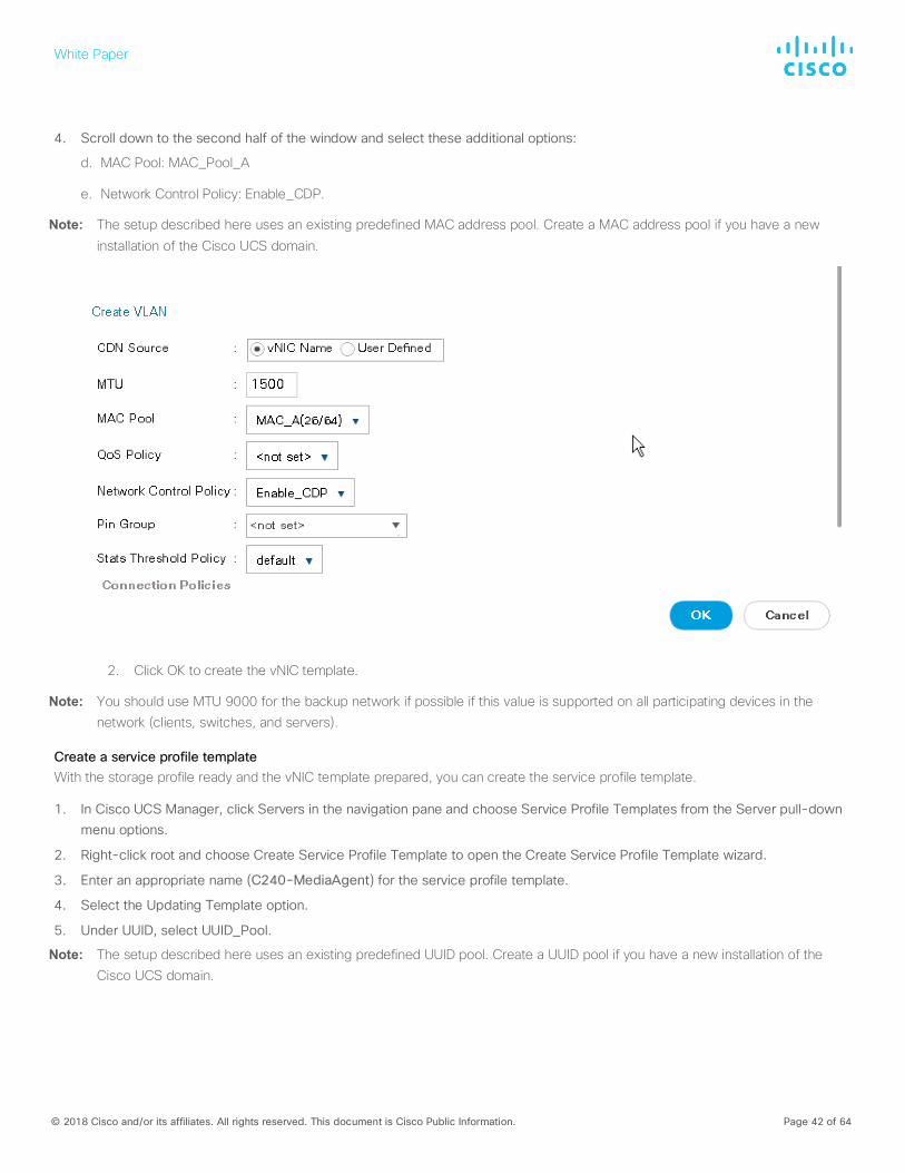
4. Scroll down to the second half of the window and select these additional options:
d. MAC Pool: MAC_Pool_A
e. Network Control Policy: Enable_CDP.
Note: The setup described here uses an existing predefined MAC address pool. Create a MAC address pool if you have a new
installation of the Cisco UCS domain.
2. Click OK to create the vNIC template.
Note: You should use MTU 9000 for the backup network if possible if this value is supported on all participating devices in the network (clients, switches, and servers).
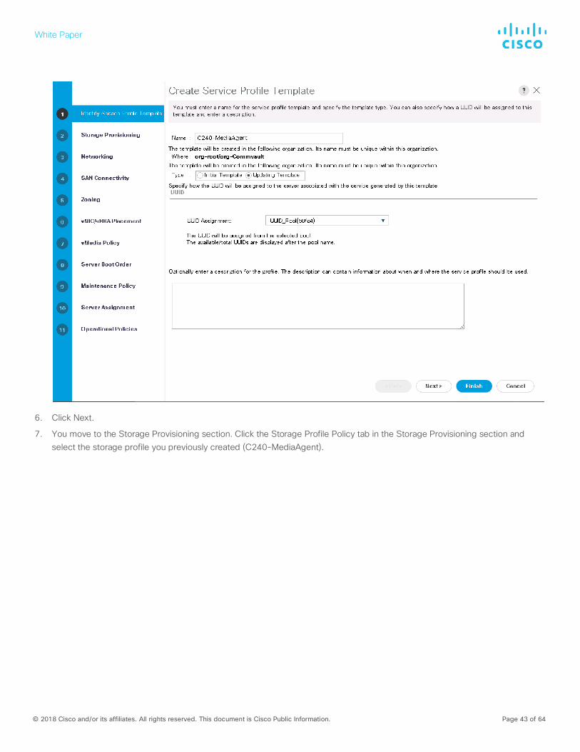
Create a service profile template With the storage profile ready and the vNIC template prepared, you can create the service profile template.
1. In Cisco UCS Manager, click Servers in the navigation pane and choose Service Profile Templates from the Server pull-down menu options.
2. Right-click root and choose Create Service Profile Template to open the Create Service Profile Template wizard.
3. Enter an appropriate name (C240-MediaAgent) for the service profile template.
4. Select the Updating Template option.
5. Under UUID, select UUID_Pool.
Note: The setup described here uses an existing predefined UUID pool. Create a UUID pool if you have a new installation of the Cisco UCS domain.
White Paper
© 2018 Cisco and/or its affiliates. All rights reserved. This document is Cisco Public Information. Page 43 of 64
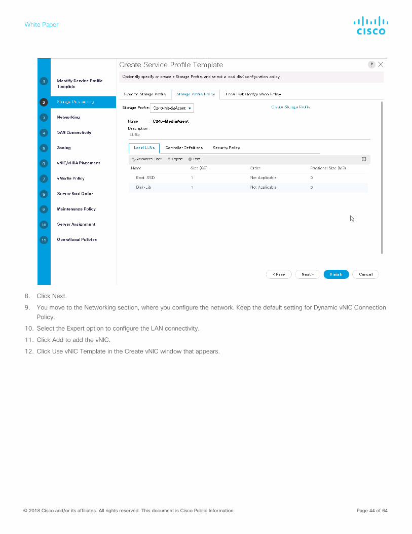
6. Click Next.
7. You move to the Storage Provisioning section. Click the Storage Profile Policy tab in the Storage Provisioning section and select the storage profile you previously created (C240-MediaAgent).
White Paper
© 2018 Cisco and/or its affiliates. All rights reserved. This document is Cisco Public Information. Page 44 of 64
8. Click Next.
9. You move to the Networking section, where you configure the network. Keep the default setting for Dynamic vNIC Connection Policy.
10. Select the Expert option to configure the LAN connectivity.
11. Click Add to add the vNIC.
12. Click Use vNIC Template in the Create vNIC window that appears.
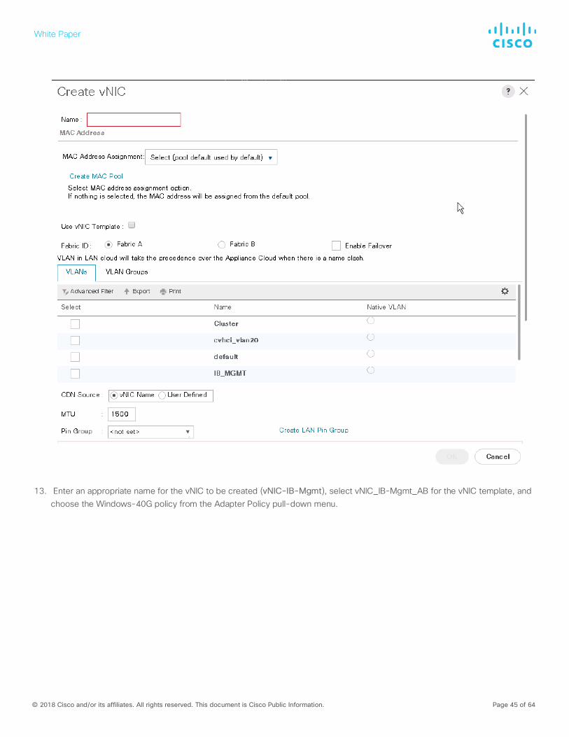
White Paper
© 2018 Cisco and/or its affiliates. All rights reserved. This document is Cisco Public Information. Page 45 of 64
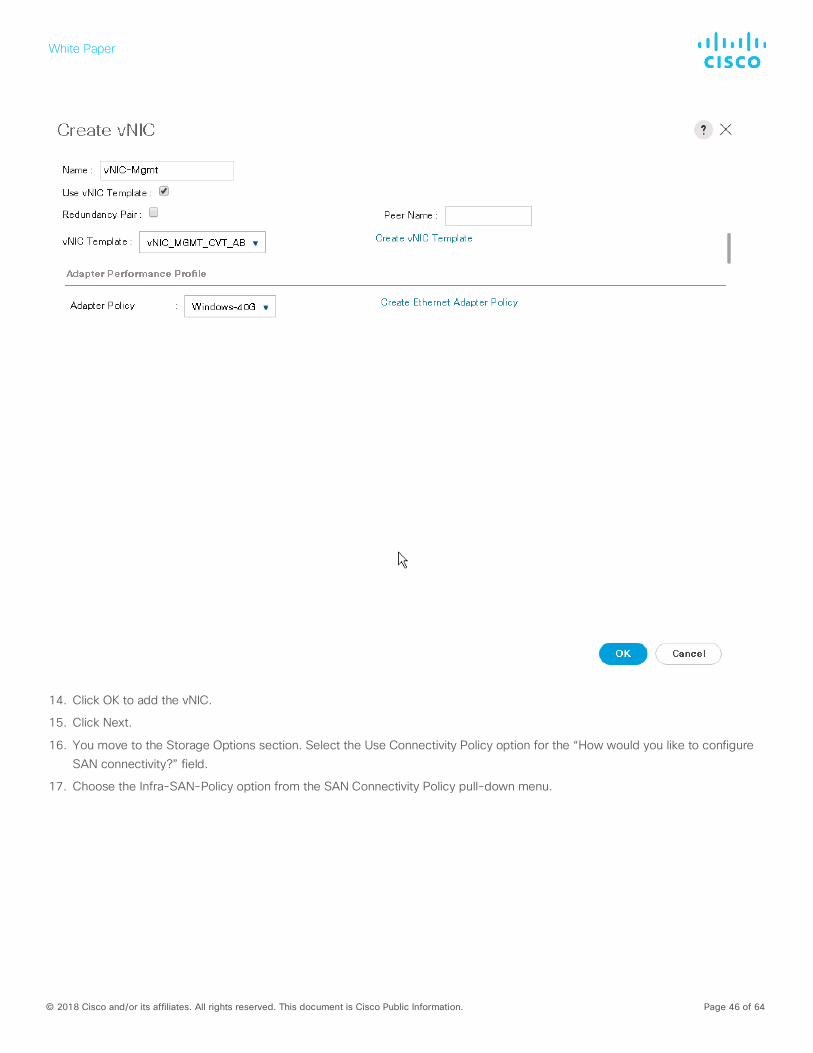
13. Enter an appropriate name for the vNIC to be created (vNIC-IB-Mgmt), select vNIC_IB-Mgmt_AB for the vNIC template, and choose the Windows-40G policy from the Adapter Policy pull-down menu.
White Paper
© 2018 Cisco and/or its affiliates. All rights reserved. This document is Cisco Public Information. Page 46 of 64
14. Click OK to add the vNIC.
15. Click Next.
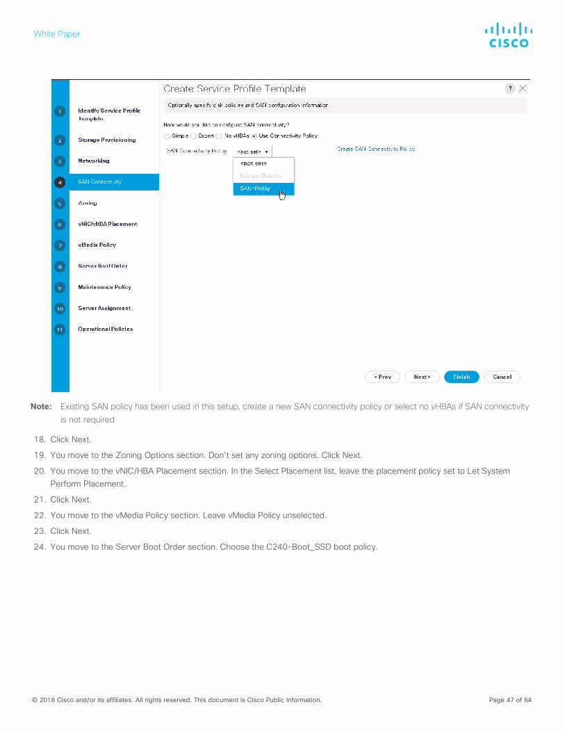
16. You move to the Storage Options section. Select the Use Connectivity Policy option for the “How would you like to configure SAN connectivity?” field.
17. Choose the Infra-SAN-Policy option from the SAN Connectivity Policy pull-down menu.
White Paper
© 2018 Cisco and/or its affiliates. All rights reserved. This document is Cisco Public Information. Page 47 of 64
Note: Existing SAN policy has been used in this setup, create a new SAN connectivity policy or select no vHBAs if SAN connectivity
is not required
18. Click Next.
19. You move to the Zoning Options section. Don’t set any zoning options. Click Next.
20. You move to the vNIC/HBA Placement section. In the Select Placement list, leave the placement policy set to Let System Perform Placement.
21. Click Next.
22. You move to the vMedia Policy section. Leave vMedia Policy unselected.
23. Click Next.
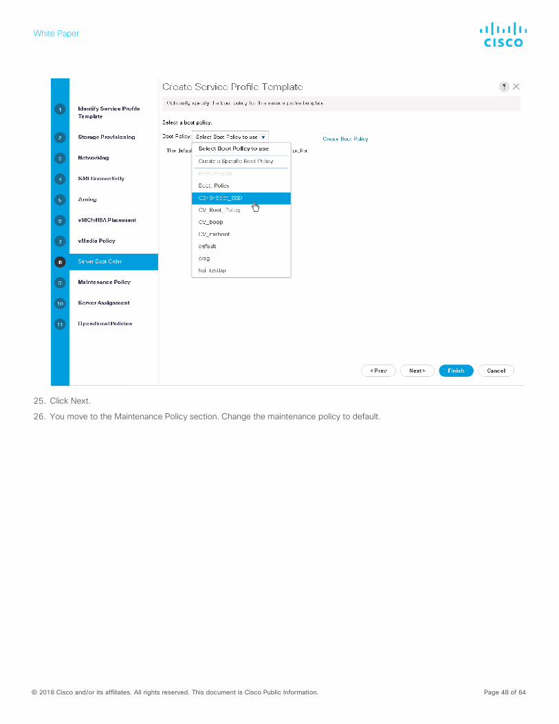
24. You move to the Server Boot Order section. Choose the C240-Boot_SSD boot policy.
White Paper
© 2018 Cisco and/or its affiliates. All rights reserved. This document is Cisco Public Information. Page 48 of 64
25. Click Next.
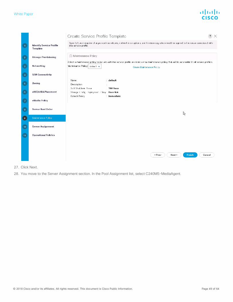
26. You move to the Maintenance Policy section. Change the maintenance policy to default.
White Paper
© 2018 Cisco and/or its affiliates. All rights reserved. This document is Cisco Public Information. Page 49 of 64
27. Click Next.
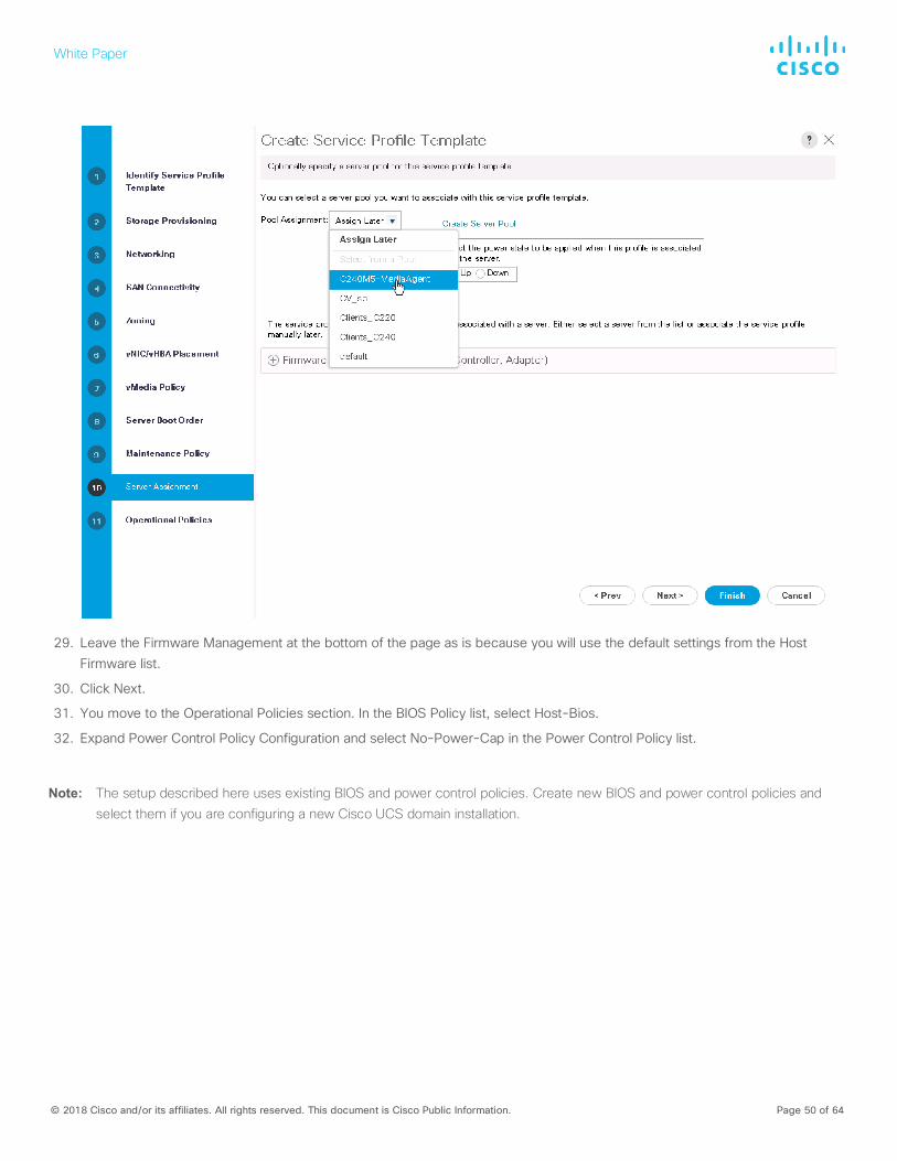
28. You move to the Server Assignment section. In the Pool Assignment list, select C240M5-MediaAgent.
White Paper
© 2018 Cisco and/or its affiliates. All rights reserved. This document is Cisco Public Information. Page 50 of 64
29. Leave the Firmware Management at the bottom of the page as is because you will use the default settings from the Host Firmware list.
30. Click Next.
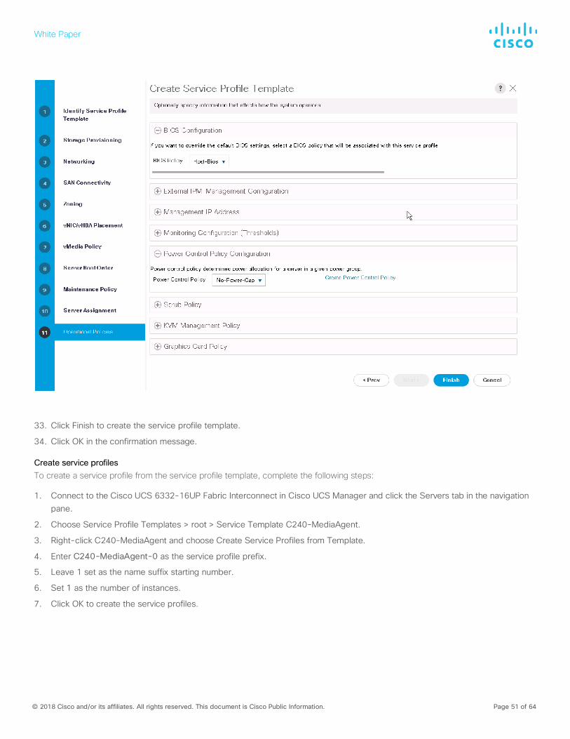
31. You move to the Operational Policies section. In the BIOS Policy list, select Host-Bios.
32. Expand Power Control Policy Configuration and select No-Power-Cap in the Power Control Policy list.
Note: The setup described here uses existing BIOS and power control policies. Create new BIOS and power control policies and select them if you are configuring a new Cisco UCS domain installation.
White Paper
© 2018 Cisco and/or its affiliates. All rights reserved. This document is Cisco Public Information. Page 51 of 64
33. Click Finish to create the service profile template.
34. Click OK in the confirmation message.
Create service profiles To create a service profile from the service profile template, complete the following steps:
1. Connect to the Cisco UCS 6332-16UP Fabric Interconnect in Cisco UCS Manager and click the Servers tab in the navigation pane.
2. Choose Service Profile Templates > root > Service Template C240-MediaAgent.
3. Right-click C240-MediaAgent and choose Create Service Profiles from Template.
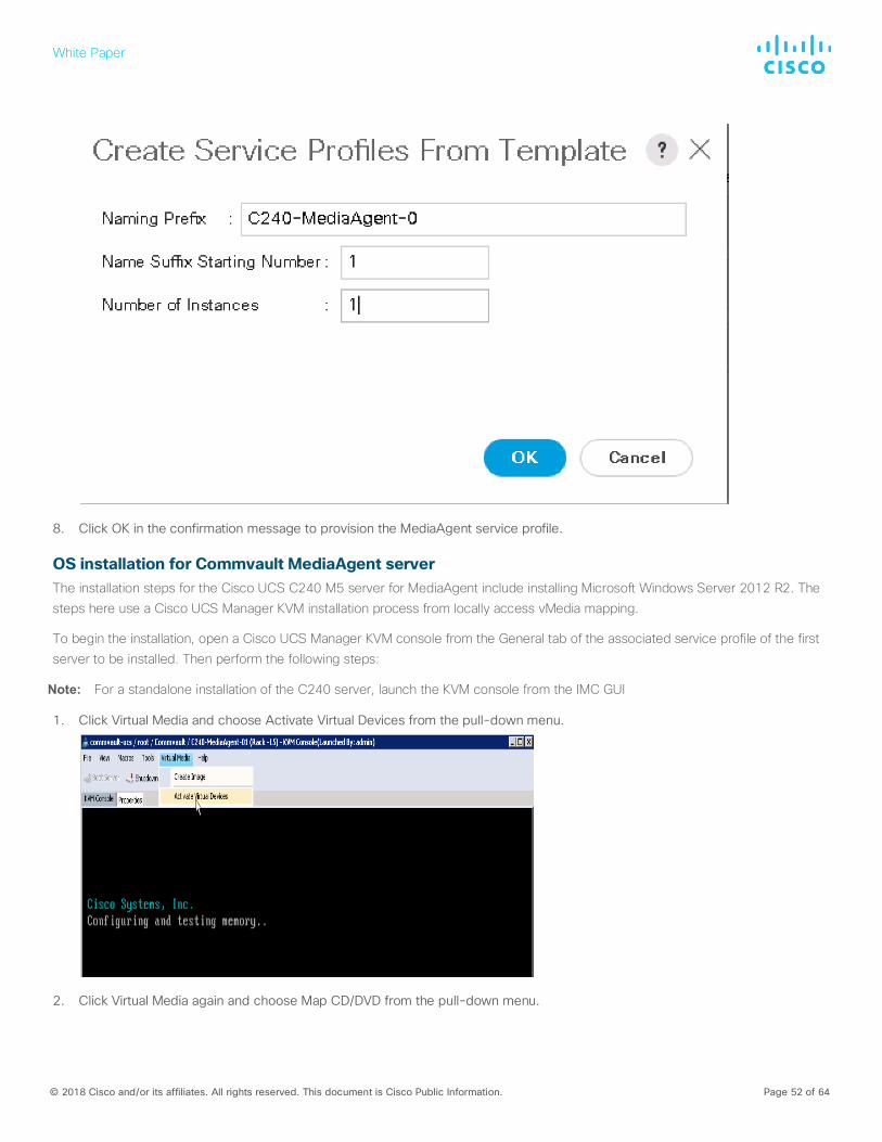
4. Enter C240-MediaAgent-0 as the service profile prefix.
5. Leave 1 set as the name suffix starting number.
6. Set 1 as the number of instances.
7. Click OK to create the service profiles.
White Paper
© 2018 Cisco and/or its affiliates. All rights reserved. This document is Cisco Public Information. Page 52 of 64
8. Click OK in the confirmation message to provision the MediaAgent service profile.
OS installation for Commvault MediaAgent server The installation steps for the Cisco UCS C240 M5 server for MediaAgent include installing Microsoft Windows Server 2012 R2. The steps here use a Cisco UCS Manager KVM installation process from locally access vMedia mapping.
To begin the installation, open a Cisco UCS Manager KVM console from the General tab of the associated service profile of the first server to be installed. Then perform the following steps:
Note: For a standalone installation of the C240 server, launch the KVM console from the IMC GUI
1. Click Virtual Media and choose Activate Virtual Devices from the pull-down menu.
2. Click Virtual Media again and choose Map CD/DVD from the pull-down menu.
White Paper
© 2018 Cisco and/or its affiliates. All rights reserved. This document is Cisco Public Information. Page 53 of 64
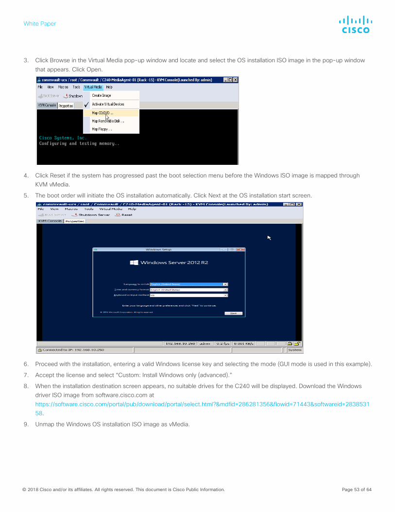
3. Click Browse in the Virtual Media pop-up window and locate and select the OS installation ISO image in the pop-up window that appears. Click Open.
4. Click Reset if the system has progressed past the boot selection menu before the Windows ISO image is mapped through KVM vMedia.
5. The boot order will initiate the OS installation automatically. Click Next at the OS installation start screen.
6. Proceed with the installation, entering a valid Windows license key and selecting the mode (GUI mode is used in this example).
7. Accept the license and select “Custom: Install Windows only (advanced).”
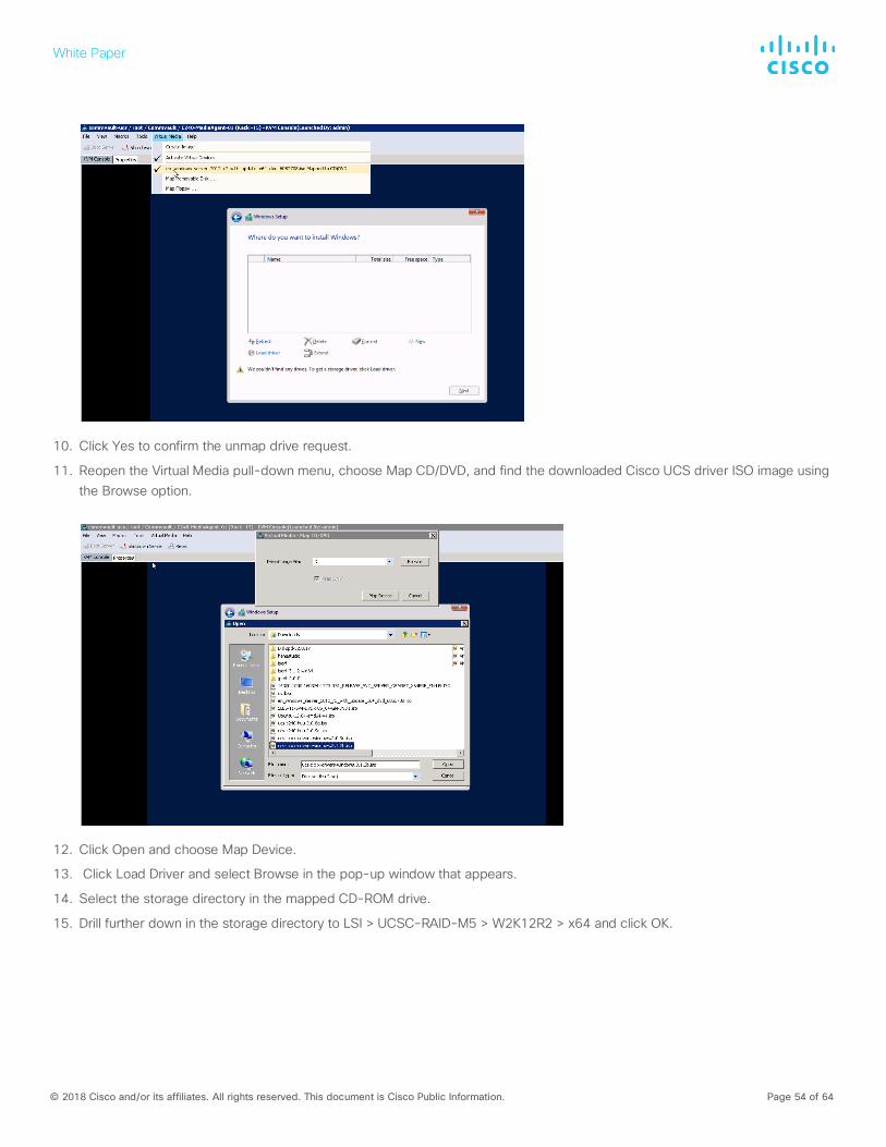
8. When the installation destination screen appears, no suitable drives for the C240 will be displayed. Download the Windows driver ISO image from software.cisco.com at https://software.cisco.com/portal/pub/download/portal/select.html?&mdfid=286281356&flowid=71443&softwareid=283853158.
9. Unmap the Windows OS installation ISO image as vMedia.
White Paper
© 2018 Cisco and/or its affiliates. All rights reserved. This document is Cisco Public Information. Page 54 of 64
10. Click Yes to confirm the unmap drive request.
11. Reopen the Virtual Media pull-down menu, choose Map CD/DVD, and find the downloaded Cisco UCS driver ISO image using the Browse option.
12. Click Open and choose Map Device.
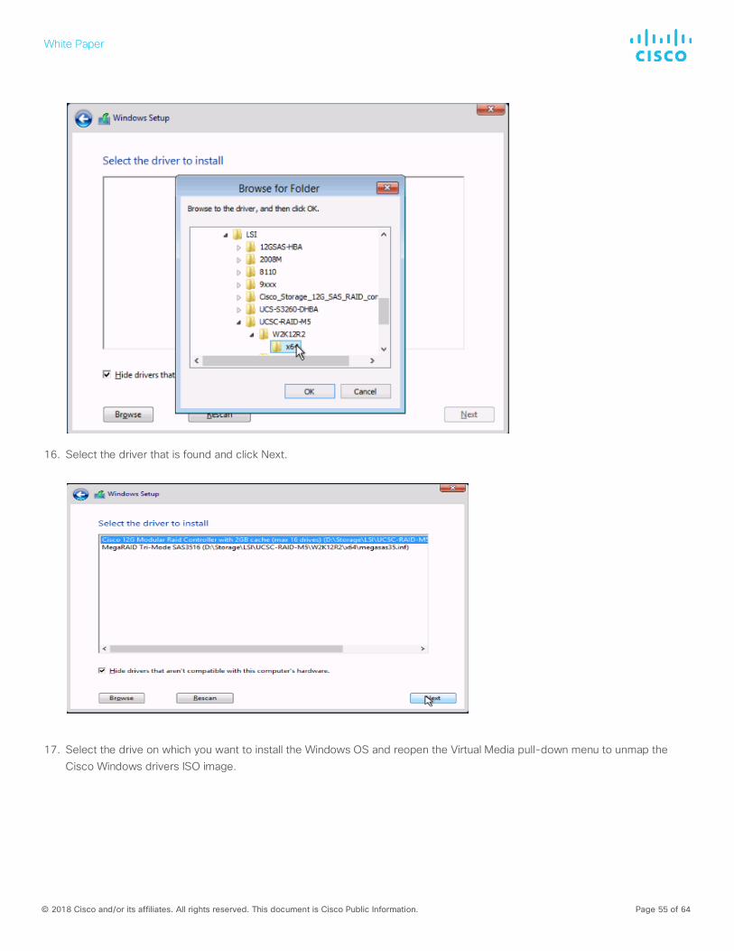
13. Click Load Driver and select Browse in the pop-up window that appears.
14. Select the storage directory in the mapped CD-ROM drive.
15. Drill further down in the storage directory to LSI > UCSC-RAID-M5 > W2K12R2 > x64 and click OK.
White Paper
© 2018 Cisco and/or its affiliates. All rights reserved. This document is Cisco Public Information. Page 55 of 64
16. Select the driver that is found and click Next.
17. Select the drive on which you want to install the Windows OS and reopen the Virtual Media pull-down menu to unmap the Cisco Windows drivers ISO image.
White Paper
© 2018 Cisco and/or its affiliates. All rights reserved. This document is Cisco Public Information. Page 56 of 64
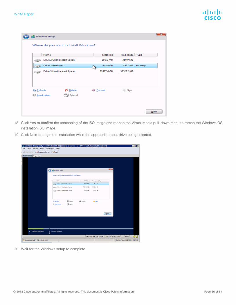
18. Click Yes to confirm the unmapping of the ISO image and reopen the Virtual Media pull-down menu to remap the Windows OS installation ISO image.
19. Click Next to begin the installation while the appropriate boot drive being selected.
20. Wait for the Windows setup to complete.
White Paper
© 2018 Cisco and/or its affiliates. All rights reserved. This document is Cisco Public Information. Page 57 of 64
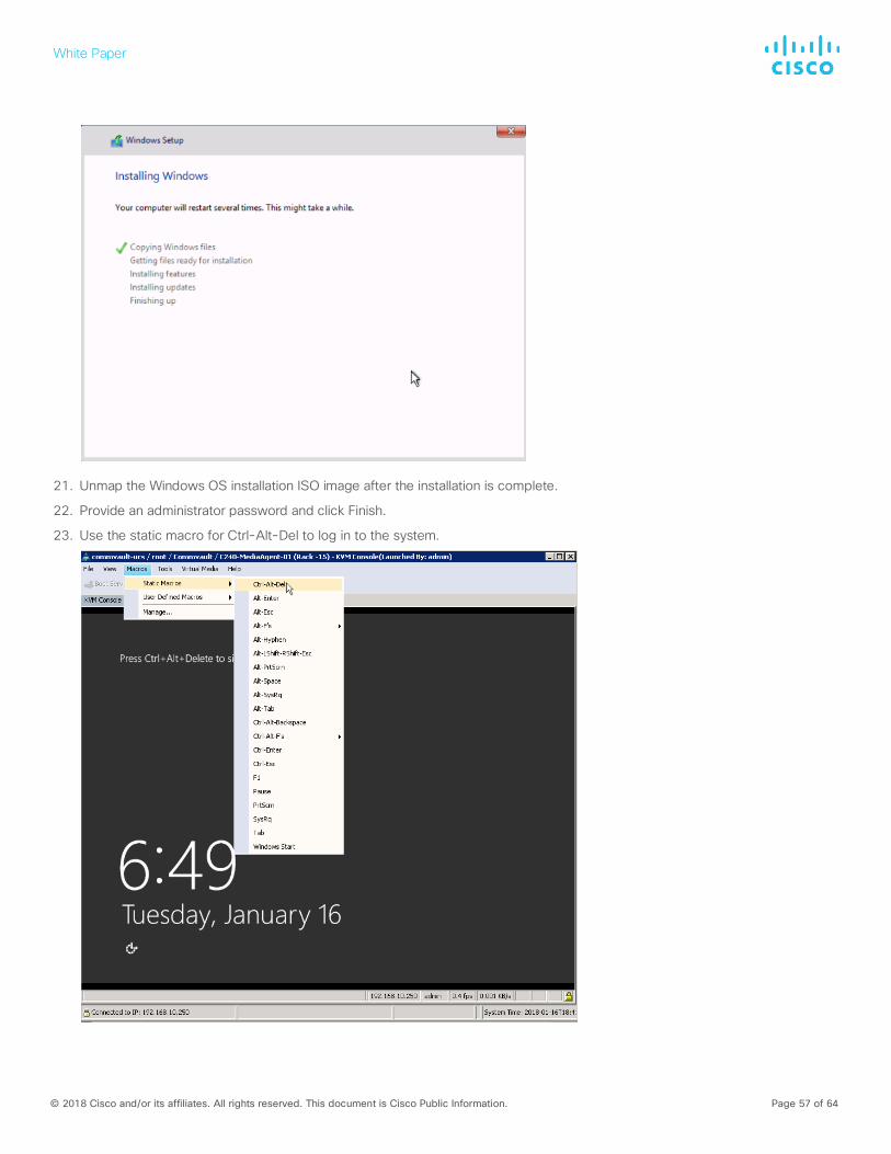
21. Unmap the Windows OS installation ISO image after the installation is complete.
22. Provide an administrator password and click Finish.
23. Use the static macro for Ctrl-Alt-Del to log in to the system.

White Paper
© 2018 Cisco and/or its affiliates. All rights reserved. This document is Cisco Public Information. Page 58 of 64
24. Reopen the Virtual Media pull-down menu and go through the steps to remap the Cisco UCS drivers for the Windows ISO image.
25. Open Device Manager and find the unidentified Ethernet controller device under Other Devices. Right-click and choose Update Driver Software.
White Paper
© 2018 Cisco and/or its affiliates. All rights reserved. This document is Cisco Public Information. Page 59 of 64
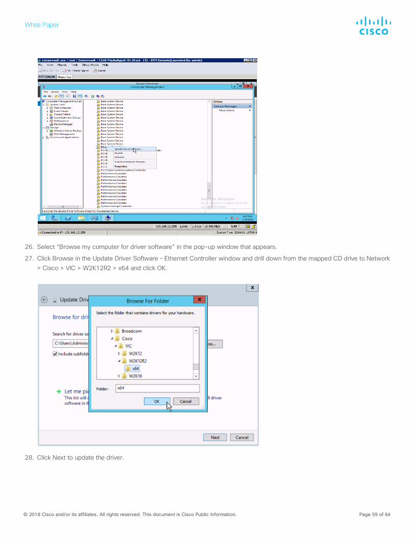
26. Select “Browse my computer for driver software” in the pop-up window that appears.
27. Click Browse in the Update Driver Software – Ethernet Controller window and drill down from the mapped CD drive to Network > Cisco > VIC > W2K12R2 > x64 and click OK.
28. Click Next to update the driver.
White Paper
© 2018 Cisco and/or its affiliates. All rights reserved. This document is Cisco Public Information. Page 60 of 64
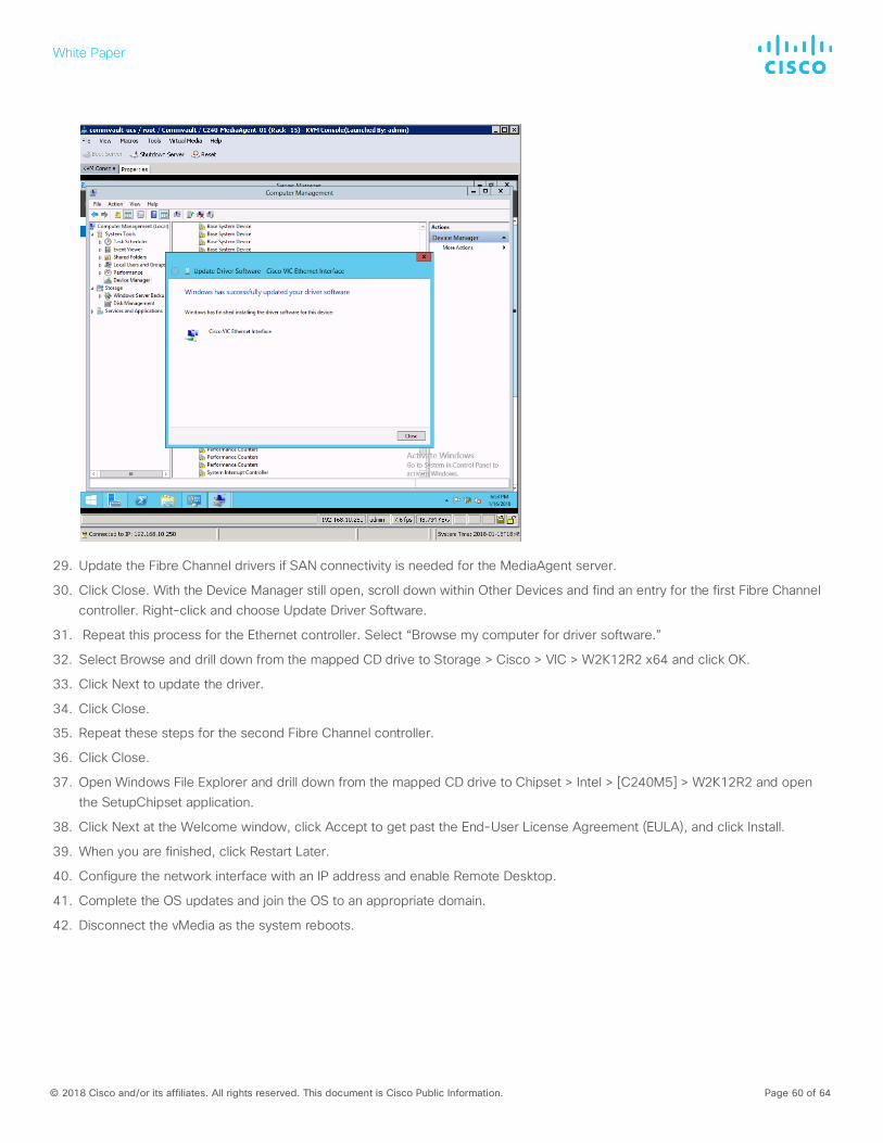
29. Update the Fibre Channel drivers if SAN connectivity is needed for the MediaAgent server.
30. Click Close. With the Device Manager still open, scroll down within Other Devices and find an entry for the first Fibre Channel controller. Right-click and choose Update Driver Software.
31. Repeat this process for the Ethernet controller. Select “Browse my computer for driver software.”
32. Select Browse and drill down from the mapped CD drive to Storage > Cisco > VIC > W2K12R2 x64 and click OK.
33. Click Next to update the driver.
34. Click Close.
35. Repeat these steps for the second Fibre Channel controller.
36. Click Close.
37. Open Windows File Explorer and drill down from the mapped CD drive to Chipset > Intel > [C240M5] > W2K12R2 and open the SetupChipset application.
38. Click Next at the Welcome window, click Accept to get past the End-User License Agreement (EULA), and click Install.
39. When you are finished, click Restart Later.
40. Configure the network interface with an IP address and enable Remote Desktop.
41. Complete the OS updates and join the OS to an appropriate domain.
42. Disconnect the vMedia as the system reboots.
White Paper
© 2018 Cisco and/or its affiliates. All rights reserved. This document is Cisco Public Information. Page 61 of 64
Commvault MediaAgent installation and configuration To deploy the MediaAgent software on the Cisco servers, use the following steps for remote deployment of the software:
1. From the CommCell Console ribbon, on the Tools tab, click Add/Remove Software. Then choose Install Software from the drop-down menu.
2. The Install Wizard will appear. Click Next.
3. On the “Select the computer’s operating system” page, select the OS and click Next.
4. On the “Select how to discover the computers for installing the software” page, click Next.
5. On the Select the computer’s operating system” page, select the OS and click Next.
6. On the “Enter the host names of the computers” page, enter the host names or IP addresses of any Cisco servers that will host the MediaAgent role. Then click Next.
7. On the Enter Account Information page, enter credentials for a user with local administrator or root privileges on the server and click Next.
8. On the Select Package(s) to Install page, select the MediaAgent package and click Next.
9. On the Optional Settings page, select the “Index cache to this folder” checkbox and enter I:\indexcache in the Index Cache path field. Then click Next.
10. On the Firewall Configuration page, click Next.
11. On the Please Select When To Run The Job page, click Next.
12. On the Summary page, click Finish. An install software job will be initiated. Monitor this job in the job controller window.
After the MediaAgent software is installed, you need to create the storage pool. This process will configure the disk library and create a storage policy so that clients can back up their data. More than one storage pool may be required depending on the design. For the drive dedicated for the disk library, format the drive with an OS block size of 64 KB.
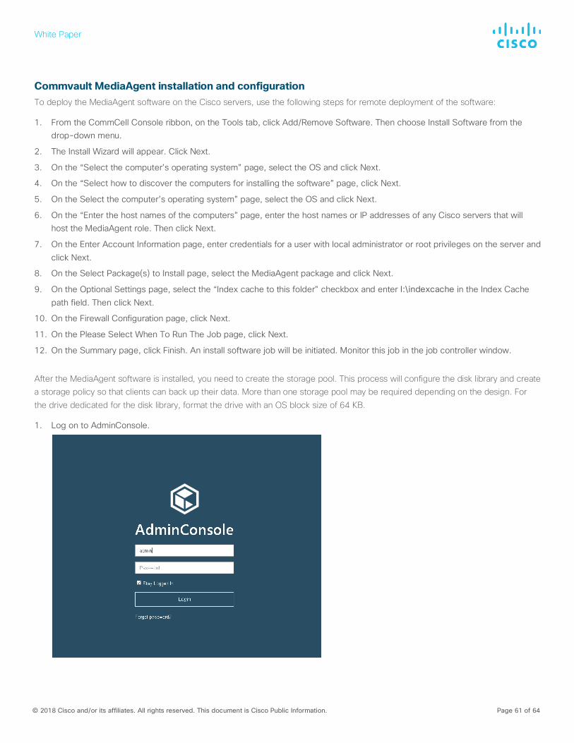
1. Log on to AdminConsole.
White Paper
© 2018 Cisco and/or its affiliates. All rights reserved. This document is Cisco Public Information. Page 62 of 64
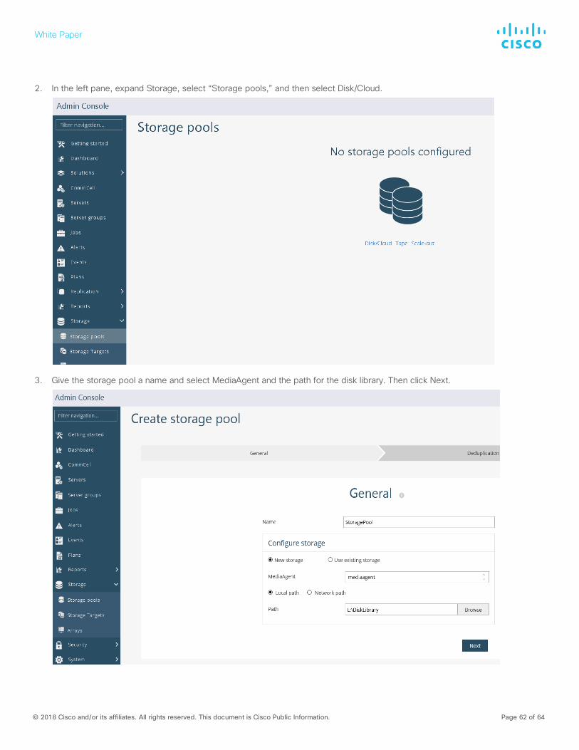
2. In the left pane, expand Storage, select “Storage pools,” and then select Disk/Cloud.
3. Give the storage pool a name and select MediaAgent and the path for the disk library. Then click Next.
White Paper
© 2018 Cisco and/or its affiliates. All rights reserved. This document is Cisco Public Information. Page 63 of 64
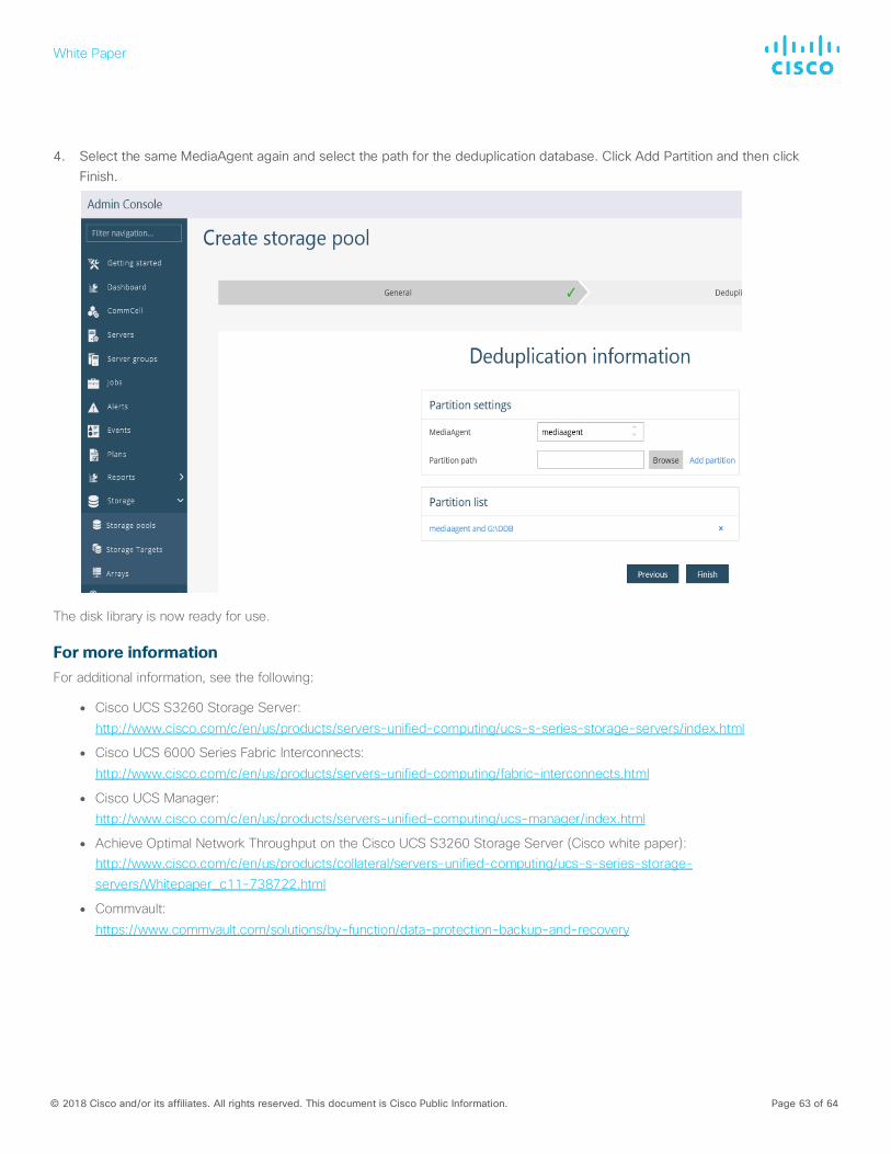
4. Select the same MediaAgent again and select the path for the deduplication database. Click Add Partition and then click
Finish.
The disk library is now ready for use.
For more information For additional information, see the following:
● Cisco UCS S3260 Storage Server:
http://www.cisco.com/c/en/us/products/servers-unified-computing/ucs-s-series-storage-servers/index.html
● Cisco UCS 6000 Series Fabric Interconnects:
http://www.cisco.com/c/en/us/products/servers-unified-computing/fabric-interconnects.html
● Cisco UCS Manager: http://www.cisco.com/c/en/us/products/servers-unified-computing/ucs-manager/index.html
● Achieve Optimal Network Throughput on the Cisco UCS S3260 Storage Server (Cisco white paper): http://www.cisco.com/c/en/us/products/collateral/servers-unified-computing/ucs-s-series-storage-servers/Whitepaper_c11-738722.html
● Commvault:
https://www.commvault.com/solutions/by-function/data-protection-backup-and-recovery

White Paper
© 2018 Cisco and/or its affiliates. All rights reserved. This document is Cisco Public Information. Page 64 of 64
Printed in USA C11-740207-00 02/18