Embed Size (px)
Citation preview
COMOS
ProcessPipeSpec Designer
Operating Manual
05/2016 V 10.2A5E37093218-AA
Legal notice 1
Publisher 2
Introduction 3Preparing for creation and maintenance of pipe specs 4Calling the PipeSpec Designer 5Loading a pipe spec in PipeSpec Designer 6
Generating pipe specs 7
Managing pipe specs 8
Configuring pipe specs 9
Documenting pipe specs 10Creating a revision of pipe specs 11
Defining bolted connections 12P&ID 3D pipe part catalog interaction 13"Error analysis for 3D objects" plugin 14
Database reference 15
User interface reference 16
Legal informationWarning notice system
This manual contains notices you have to observe in order to ensure your personal safety, as well as to prevent damage to property. The notices referring to your personal safety are highlighted in the manual by a safety alert symbol, notices referring only to property damage have no safety alert symbol. These notices shown below are graded according to the degree of danger.
DANGERindicates that death or severe personal injury will result if proper precautions are not taken.
WARNINGindicates that death or severe personal injury may result if proper precautions are not taken.
CAUTIONindicates that minor personal injury can result if proper precautions are not taken.
NOTICEindicates that property damage can result if proper precautions are not taken.If more than one degree of danger is present, the warning notice representing the highest degree of danger will be used. A notice warning of injury to persons with a safety alert symbol may also include a warning relating to property damage.
Qualified PersonnelThe product/system described in this documentation may be operated only by personnel qualified for the specific task in accordance with the relevant documentation, in particular its warning notices and safety instructions. Qualified personnel are those who, based on their training and experience, are capable of identifying risks and avoiding potential hazards when working with these products/systems.
Proper use of Siemens productsNote the following:
WARNINGSiemens products may only be used for the applications described in the catalog and in the relevant technical documentation. If products and components from other manufacturers are used, these must be recommended or approved by Siemens. Proper transport, storage, installation, assembly, commissioning, operation and maintenance are required to ensure that the products operate safely and without any problems. The permissible ambient conditions must be complied with. The information in the relevant documentation must be observed.
TrademarksAll names identified by ® are registered trademarks of Siemens AG. The remaining trademarks in this publication may be trademarks whose use by third parties for their own purposes could violate the rights of the owner.
Disclaimer of LiabilityWe have reviewed the contents of this publication to ensure consistency with the hardware and software described. Since variance cannot be precluded entirely, we cannot guarantee full consistency. However, the information in this publication is reviewed regularly and any necessary corrections are included in subsequent editions.
Siemens AGDivision Process Industries and DrivesPostfach 48 4890026 NÜRNBERGGERMANY
A5E37093218-AAⓅ 04/2016 Subject to change
Copyright © Siemens AG 2013 - 2016.All rights reserved
Table of contents
1 Legal notice..................................................................................................................................................9
2 Publisher.....................................................................................................................................................11
3 Introduction.................................................................................................................................................13
3.1 Application range of the PipeSpec Designer..........................................................................13
3.2 Classes managed in PipeSpec Designer...............................................................................13
4 Preparing for creation and maintenance of pipe specs..............................................................................15
4.1 Basic procedure for preparation.............................................................................................15
4.2 Customizing project settings..................................................................................................15
4.3 Managing standard tables......................................................................................................164.3.1 Parameters dependent on the system of standards..............................................................164.3.2 Managing standard tables for parameters.............................................................................174.3.2.1 Definition of parameters.........................................................................................................174.3.2.2 Information on editing parameters.........................................................................................184.3.2.3 Creating a new parameter......................................................................................................184.3.3 Standard tables for nominal diameters..................................................................................194.3.4 Hiding values from standard tables........................................................................................194.3.5 Inserting the "Obsolete" column in standard tables...............................................................20
4.4 Managing the "standard geometry tables" standard catalog..................................................214.4.1 Introduction in the "standard geometry tables" standard catalog...........................................214.4.2 Structure of the standard catalog for geometry standards.....................................................234.4.2.1 Structure parameters.............................................................................................................234.4.2.2 Structuring by the "Parameter name" attribute.......................................................................244.4.2.3 Extending the "Standard parameterization table"..................................................................25
4.5 Administering pipe part catalogs............................................................................................274.5.1 Structure of the pipe part catalogs.........................................................................................274.5.2 Determining the component geometry of a pipe part.............................................................284.5.2.1 Configuring the geometry attributes.......................................................................................284.5.2.2 Entering the calculation formula.............................................................................................304.5.2.3 Using the "Define catalog access" window............................................................................314.5.2.4 Overview of the calculation formulae.....................................................................................314.5.2.5 Using the "CatStd(...)" function..............................................................................................324.5.2.6 Using the "Cat(...)" function....................................................................................................364.5.2.7 Using the "Cat2(...)" function..................................................................................................364.5.2.8 Using the "S(...)" function.......................................................................................................374.5.2.9 Using the "ElmS(...)" function.................................................................................................374.5.2.10 Using the "CatExt(...)" function...............................................................................................384.5.2.11 Using the "CatPC(...)" function...............................................................................................394.5.2.12 "Def(...)" function....................................................................................................................394.5.3 Nominal diameter range of a pipe part...................................................................................404.5.3.1 Introduction to nominal diameter ranges................................................................................404.5.3.2 Display nominal diameter range.............................................................................................40
PipeSpec DesignerOperating Manual, 05/2016 V 10.2, A5E37093218-AA 3
4.5.3.3 New calculation of the nominal diameter range.....................................................................414.5.3.4 Restricting the nominal diameter range of a pipe part...........................................................414.5.3.5 Integration into existing databases.........................................................................................424.5.4 Extending a pipe part catalog.................................................................................................434.5.4.1 Creating a new catalog..........................................................................................................434.5.4.2 Creating a new pipe part........................................................................................................444.5.5 "Part description" tab..............................................................................................................444.5.6 "Part specification" tab...........................................................................................................454.5.6.1 Control group "Pressure/temperature dependency"..............................................................454.5.6.2 Control group "Materials – List of objects".............................................................................464.5.6.3 Control group "Technical Terms of Delivery".........................................................................464.5.7 "Datasheet" tab......................................................................................................................464.5.7.1 Control group "Manufacturer data".........................................................................................464.5.7.2 Nominal size dependent table................................................................................................474.5.8 "Local dimensions (NPS)" tab................................................................................................474.5.9 "Text blocks" tab....................................................................................................................484.5.10 "Interface codes" tab..............................................................................................................494.5.11 "System information" tab........................................................................................................494.5.12 "Data maintenance" tab.........................................................................................................504.5.13 "Fabrication" tab.....................................................................................................................504.5.14 "Comments" tab.....................................................................................................................504.5.15 "3D geometry" tab..................................................................................................................504.5.15.1 "General" control group..........................................................................................................504.5.15.2 "Nominal sizes / connection types" control group..................................................................514.5.15.3 "General geometry description" control group.......................................................................524.5.16 "Connector <1-n>" tab............................................................................................................524.5.17 "Display for nominal diameter range" tab...............................................................................53
4.6 Creating a pipe part type........................................................................................................544.6.1 Creating a pipe part type........................................................................................................544.6.2 Standard table for function codes..........................................................................................54
4.7 Managing standards...............................................................................................................554.7.1 Creating a new system of standards......................................................................................554.7.1.1 Overview: Creating a new system of standards.....................................................................554.7.1.2 Creating standard tables for a system of standards...............................................................564.7.1.3 Extending a system of standards in the "standard geometry tables".....................................574.7.1.4 Adding attributes or tabs for the "standard geometry tables".................................................574.7.1.5 Extending a system of standards in the pipe part catalog......................................................584.7.2 Extending a standard in a system of standards.....................................................................594.7.2.1 Creating geometry standards.................................................................................................594.7.2.2 Adding values to the geometry tables....................................................................................604.7.2.3 Configuring geometry standards for bolts..............................................................................604.7.2.4 Configuring geometry standards for nuts and washers..........................................................61
5 Calling the PipeSpec Designer...................................................................................................................63
6 Loading a pipe spec in PipeSpec Designer................................................................................................65
7 Generating pipe specs................................................................................................................................67
7.1 Options for creating a new pipe spec.....................................................................................67
7.2 Creating a new pipe spec without a template........................................................................67
7.3 Creating a new pipe spec from a template.............................................................................68
Table of contents
PipeSpec Designer4 Operating Manual, 05/2016 V 10.2, A5E37093218-AA
7.4 The "Load pipe spec" window................................................................................................69
8 Managing pipe specs..................................................................................................................................71
8.1 Deleting a pipe spec...............................................................................................................71
8.2 Creating folders for structuring the pipe specs.......................................................................71
9 Configuring pipe specs...............................................................................................................................73
9.1 Overview for configuring pipe specs......................................................................................73
9.2 Configuring the "PipeSpec limits" tab.....................................................................................749.2.1 Choosing a system of standards............................................................................................749.2.2 Defining the nominal diameter range.....................................................................................749.2.3 Defining the application limits of the spec..............................................................................759.2.4 Defining the application limits of the media............................................................................769.2.5 Defining the outer diameter and wall thickness......................................................................77
9.3 Configuring the "Characteristics" tab.....................................................................................789.3.1 Defining the fluid characteristics of the spec..........................................................................789.3.2 Defining the fluid group according to the DGRL.....................................................................789.3.3 Defining other characteristics of the pipe spec......................................................................799.3.4 Defining nominal-diameter-dependent parameters................................................................79
9.4 Configuring the "Components" tab.........................................................................................819.4.1 Pipe parts table......................................................................................................................819.4.2 Assigning a new pipe part......................................................................................................829.4.3 Navigating to the pipe part.....................................................................................................839.4.4 Setting the upper and lower limits of the DN range of a pipe part..........................................839.4.5 Adding a component to the branch table...............................................................................84
9.5 "Nominal diameters" tab:........................................................................................................849.5.1 Surface reference of the "Nominal diameter" tab...................................................................859.5.2 Preselected components........................................................................................................869.5.3 Defining preselected components..........................................................................................869.5.4 Limiting nominal diameter ranges..........................................................................................889.5.5 Updating the legend...............................................................................................................89
9.6 "Branch table" tab..................................................................................................................899.6.1 Surface reference of the "Branch table" tab...........................................................................899.6.2 Defining branch parts.............................................................................................................919.6.3 Adapting the legend...............................................................................................................929.6.4 Modifying the nominal diameter range...................................................................................939.6.5 Branch table for PDMS pipe specs........................................................................................939.6.6 Miscellaneous........................................................................................................................93
9.7 "Connector table" tab.............................................................................................................949.7.1 Surface reference of the "Connector table" tab......................................................................949.7.2 Configuring the connector table.............................................................................................959.7.3 Configuring the table for special parts....................................................................................959.7.4 Evaluation sequence..............................................................................................................969.7.5 Example application in the engineering data.........................................................................97
9.8 "Fastening table" tab..............................................................................................................999.8.1 General information................................................................................................................999.8.2 Configuring the fastening table..............................................................................................999.8.3 Resetting attachment type combinations.............................................................................100
Table of contents
PipeSpec DesignerOperating Manual, 05/2016 V 10.2, A5E37093218-AA 5
9.8.4 Updating attachment type combinations..............................................................................1019.8.5 Evaluation sequence............................................................................................................1019.8.6 Adding standard combinations.............................................................................................101
9.9 "Chart" tab............................................................................................................................1029.9.1 Content of the "Chart" tab....................................................................................................103
9.10 "Comments" tab...................................................................................................................103
9.11 "Function" tab.......................................................................................................................103
10 Documenting pipe specs..........................................................................................................................105
11 Creating a revision of pipe specs.............................................................................................................107
12 Defining bolted connections.....................................................................................................................109
12.1 Basics of bolted connections................................................................................................109
12.2 Creating bolt sets.................................................................................................................114
12.3 Specifying bolted connections at pipe parts.........................................................................117
12.4 Standard tables for bolt parts and bolt sets..........................................................................117
12.5 Using bolt sets in pipe specs................................................................................................12012.5.1 Overview of the work sequence...........................................................................................12012.5.2 Defining the strength grades of screws and nuts.................................................................12012.5.3 Adding a bolt set to the pipe spec........................................................................................12112.5.4 Adding screw parts to the pipe spec....................................................................................12112.5.5 Assigning the bolt set to a pipe part.....................................................................................12212.5.6 Creating bolt sets.................................................................................................................12312.5.7 Using a bolt set group..........................................................................................................12412.5.7.1 Adding a bolt set group to the pipe spec..............................................................................12412.5.7.2 Example of a connection via a bolt set group......................................................................12512.5.7.3 Deleting a bolt set group......................................................................................................126
13 P&ID 3D pipe part catalog interaction......................................................................................................127
13.1 Requirements for linking P&ID and 3D pipe part catalog.....................................................127
13.2 Technical details..................................................................................................................12813.2.1 Link between P&ID and pipe part catalog............................................................................12813.2.2 The pipe spec mapping sequence.......................................................................................12813.2.3 Result of pipe spec mapping................................................................................................129
13.3 Overview of the configuration sequence..............................................................................129
13.4 Adding P&ID function codes................................................................................................130
13.5 Linking the P&ID function code to the function codes..........................................................131
13.6 Configuring project properties for interaction between P&ID catalog and pipe part catalog....132
13.7 Configuring P&ID base objects............................................................................................13313.7.1 Workflow..............................................................................................................................13313.7.2 Checking the attribute for the P&ID function code...............................................................13313.7.3 Implementing branches........................................................................................................134
13.8 Configuring pipe part catalog base objects..........................................................................13413.8.1 Checking the settings necessary for linking.........................................................................13413.8.2 Checking the attribute for the function code.........................................................................135
Table of contents
PipeSpec Designer6 Operating Manual, 05/2016 V 10.2, A5E37093218-AA
13.8.3 Retaining the request as the report object...........................................................................13513.8.4 Outputting the symbol of the request on the report..............................................................136
14 "Error analysis for 3D objects" plugin.......................................................................................................137
14.1 Purpose................................................................................................................................137
14.2 Calling a plugin.....................................................................................................................137
14.3 Interface of the plugin...........................................................................................................138
14.4 Checking the pipe part geometry.........................................................................................14214.4.1 Checking the pipe part geometry for errors..........................................................................14214.4.2 Displaying 3D attributes of a pipe part.................................................................................14314.4.3 Calculating the geometry of a pipe part...............................................................................144
14.5 Nominal-diameter-dependent check of the geometry..........................................................14514.5.1 Workflow..............................................................................................................................14514.5.2 Canceling or continuing the analysis....................................................................................14614.5.3 Viewing the result of the analysis in the 3D Editor...............................................................14614.5.4 Switch to detail evaluation....................................................................................................147
15 Database reference..................................................................................................................................149
15.1 Bolted types.........................................................................................................................149
15.2 Algorithm for calculating the screw length............................................................................150
15.3 Example report for pipe spec documentation.......................................................................152
15.4 Example report for pipe part documentation........................................................................152
15.5 Pipe parts in the pipe part catalog........................................................................................15315.5.1 Tabs and attributes..............................................................................................................15315.5.2 Change DisplayValue()........................................................................................................15315.5.3 Navigator description from pipe part attributes....................................................................15415.5.4 Inheritance of the nominal diameters and pipe spec............................................................154
15.6 P&ID objects........................................................................................................................15615.6.1 Overview: Data flow between P&ID object and pipe part catalog implementation...............15615.6.2 Deactivating the standard check with "IsImplementationValid" and
"OnImplementationSet"........................................................................................................15715.6.3 Link for the "Nominal pressure" attribute..............................................................................157
16 User interface reference...........................................................................................................................159
16.1 Project properties "PipeSpec Designer" category................................................................159
16.2 Project properties "PipeSpec Manager" category................................................................160
Table of contents
PipeSpec DesignerOperating Manual, 05/2016 V 10.2, A5E37093218-AA 7

Table of contents
PipeSpec Designer8 Operating Manual, 05/2016 V 10.2, A5E37093218-AA

Legal notice 1Please observe the following notes when working with the PipeSpec Designer:
● COMOS does not supply production-ready pipe specs.
● Customers can set up their own geometry standards.
● Customers are responsible for checking the COMOS data before using it in the context of production.
You can find more information on this topic in the "COMOS readme <version 10.1.3.0.0 and newer>" manual, keyword "Standards and directives in COMOS".
PipeSpec DesignerOperating Manual, 05/2016 V 10.2, A5E37093218-AA 9

Legal notice
PipeSpec Designer10 Operating Manual, 05/2016 V 10.2, A5E37093218-AA

Publisher 2Bentley Systems
The CAD software product Microstation is a product of the Bentley Systems company and is referred to simply as Microstation in the remainder of this documentation.
AVEVAPDMS is a software product of the AVEVA company and is hereinafter referred to simply as PDMS.
PipeSpec DesignerOperating Manual, 05/2016 V 10.2, A5E37093218-AA 11

Publisher
PipeSpec Designer12 Operating Manual, 05/2016 V 10.2, A5E37093218-AA
Introduction 33.1 Application range of the PipeSpec Designer
ObjectiveThe manual provides you as administrator with a guideline for creating and managing pipe specs.
The technical requirements that are made to a pipe unit depend on the used fluids and the process conditions. In PipeSpec Designer, you define all classes that you need to plan a pipe unit:
● Fluid specs (construction classes)
● Pipe specs
● Subclasses
● Classes imported from PDMS AVEVA
You can also define project classes.
The PipeSpec Manager component gives you access to the pipe specs throughout the entire pipe engineering.
The pipe parts that are assigned to the classes come from the pipe part catalog supplied with the database and include the necessary component geometry by referencing the geometry standard. To this end, geometry data for components was set up in the database, complying with the geometry standards for DIN, EN, and ANSI/ASME. You can set up user-defined geometry standards if required.
The finished pipe spec definitions are documented in pipe spec reports; pipe parts are documented in pipe part reports.
3.2 Classes managed in PipeSpec Designer
Pipe specsA pipe spec is a specified compilation of all pipe parts that belong to a pipe.
In COMOS, the term pipe spec can also describe part classes, such as armature classes, gasket classes, or support classes. The pipe parts assigned to a nominal pressure (PN) and pipe material are clearly predefined in a corresponding design (dimensions and material) within a pipe spec.A pipe spec defined in COMOS covers most of the constructive requirements for pipe engineering.
They define the content of the pipe specs. For example, you can create a part class each for armatures, gaskets, fittings, and flanges, or you can combine all of these components in one conventional pipe spec.
PipeSpec DesignerOperating Manual, 05/2016 V 10.2, A5E37093218-AA 13
Fluid specIn P&ID engineering, if the fluid is the determining variable for the pipe spec, you can combine a variety of pipe specs into a single fluid spec.
Example: A fluid spec consisting of a pipe spec, an armature class, and a gasket class.
PDMS pipe specs● You can export pipe specs from PDMS in XML format and import them to COMOS via the
"PDMS/E3D pipe spec import" plugin.You can find more information on this topic in the "3D Integration Administration" manual, keyword "Pipe spec import from PDMS".
● You can export pipe specs from COMOS and import them into PDMS.
– Data communication is based on the data schema of COMOS and PDMS and is configured in the "Generic Data Mapper" plugin. You can find more information on this topic in the "3D Integration Administration" manual, keyword "Generic Data Mapper".
– You perform the pipe spec export in the "PDMS pipe spec export" plugin. You import the exported pipe specs into PDMS via the "PDMS/E3D Engineering Interface".You can find more information on this topic in the "3D Integration Administration" manual, keyword "Exporting COMOS pipe specs to PDMS".
Nested classesYou have the option of nesting classes. This is done by allocating a class that has already been defined (class A) to another class (class B). All components from class A are automatically available in class B and must not violate the defaults defined in class B. See also chapter Pipe parts table (Page 81).
Introduction3.2 Classes managed in PipeSpec Designer
PipeSpec Designer14 Operating Manual, 05/2016 V 10.2, A5E37093218-AA
Preparing for creation and maintenance of pipe specs 44.1 Basic procedure for preparation
To be able to create and maintain pipe specs in the PipeSpec Designer module, note the following default settings:
1. Change the settings for working with the PipeSpec Designer in the project properties, if necessary.See chapter Customizing project settings (Page 15).
2. Optional: Complete the standard tables in the database.See chapter Managing standard tables (Page 16).
3. Optional: Configure and complete the standard catalog for geometry data in the database.See chapter Managing the "standard geometry tables" standard catalog (Page 21).
4. Optional: Configure and complete the pipe part catalog in the database.See chapter Administering pipe part catalogs (Page 27).
5. Create bolt sets, if necessary.See chapter Creating bolt sets (Page 114).
4.2 Customizing project settingsThe values for working with PipeSpec Designer are preset in the "SO1" base project. The settings from the base project are automatically applied by all engineering projects.
See also chapter Project properties "PipeSpec Designer" category (Page 159).
RequirementYou are familiar with the basic procedure to prepare for creating and managing pipe specs. See also chapter Basic procedure for preparation (Page 15).
Procedure● To change the settings in the base project, open the base project properties and overwrite
the respective settings in the "PipeSpec Designer" category.
● To change the settings for one engineering project only, open the properties of the relevant engineering project and overwrite the respective settings in the "PipeSpec Designer" category.If an engineering project is to use only a project-specific pipe spec, for example, collect the project-specific pipe spec under a dedicated node and enter this node in the "PipeSpec Designer" category under "Pipe spec definition".
PipeSpec DesignerOperating Manual, 05/2016 V 10.2, A5E37093218-AA 15
4.3 Managing standard tablesThe administration of data in standard tables is part of the standard functionality of COMOS.
Standard tables are used for the following purposes in the PipeSpec Designer:
● Simplify the selection of attribute values.
● Administer parameters and their characteristics.
You can find additional information on this topic in the "Administration" manual, keyword "Administration of standard tables".
Standard tables for the PipeSpec DesignerThe standard tables that are necessary for work with PipeSpec Designer can be found under the following nodes.
● Standard-dependent standard tables:"Standard tables > Y10 > M20 > Y30 > A10 System standard depending tables"
● Standard-independent standard tables:"Standard tables > Y10 > M23 PipeSpec Designer"
See alsoDefinition of parameters (Page 17)
4.3.1 Parameters dependent on the system of standardsSome parameters must comply with the following regulations for the configuration of a pipe part:
● The values listed for selection shall always be determined by the system of standards.
● If, on the "Attributes > Part description" tab in the "Y00A00038 System of standards" attribute, the user changes the system of standards to pipe parts in the pipe part catalog, there is an automatic switch to the standard tables of the corresponding system of standards.
To meet this requirement, two attributes must be managed:
● The attribute "Y00T00059.Y00A00038 System of standards": The attribute defines which system of standards applies.
● The standard depending attribute:Its values vary within the framework specified by the system of standards.
Method for changing the system of standardsIf you select a different system of standards in the "System of standards" attribute, the script block "OnChange()" is initiated.
You can find the script at the following locations in the database:
Preparing for creation and maintenance of pipe specs4.3 Managing standard tables
PipeSpec Designer16 Operating Manual, 05/2016 V 10.2, A5E37093218-AA
At pipe parts in the pipe part catalog, "Y00T00059.Y00A00038 System of standards" attribute, "Script" attribute tab, "OnChange()" script block
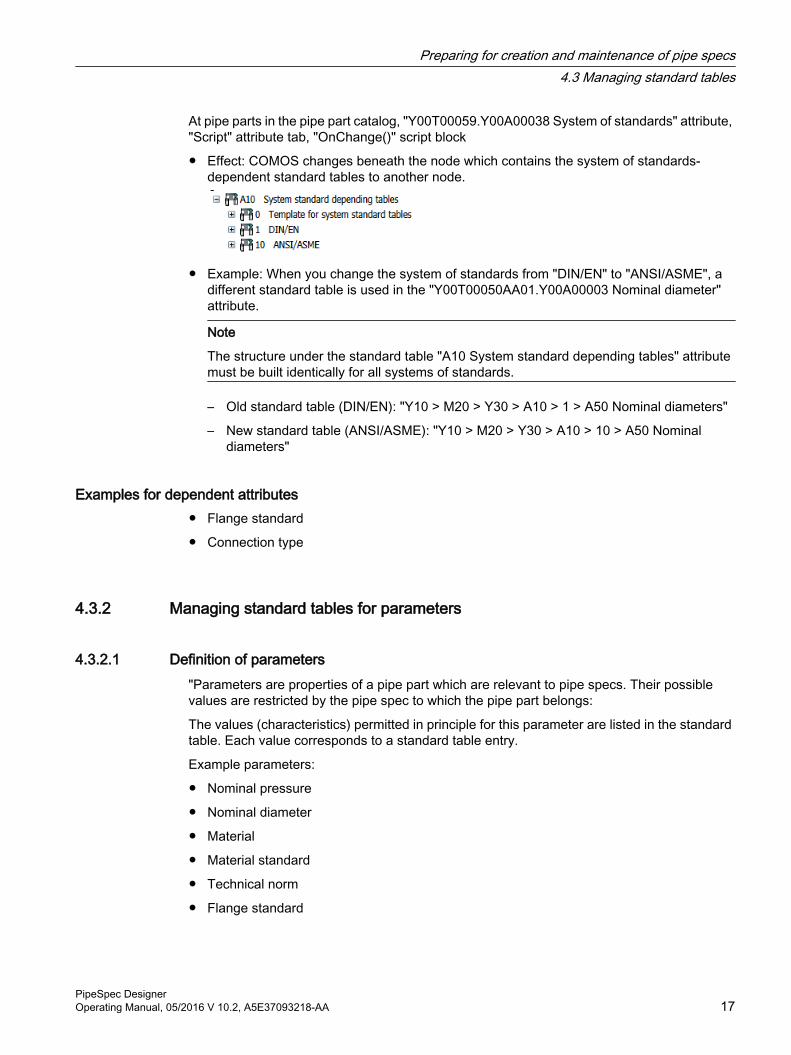
● Effect: COMOS changes beneath the node which contains the system of standards-dependent standard tables to another node.
● Example: When you change the system of standards from "DIN/EN" to "ANSI/ASME", a different standard table is used in the "Y00T00050AA01.Y00A00003 Nominal diameter" attribute.
Note
The structure under the standard table "A10 System standard depending tables" attribute must be built identically for all systems of standards.
– Old standard table (DIN/EN): "Y10 > M20 > Y30 > A10 > 1 > A50 Nominal diameters"
– New standard table (ANSI/ASME): "Y10 > M20 > Y30 > A10 > 10 > A50 Nominal diameters"
Examples for dependent attributes ● Flange standard
● Connection type
4.3.2 Managing standard tables for parameters
4.3.2.1 Definition of parameters"Parameters are properties of a pipe part which are relevant to pipe specs. Their possible values are restricted by the pipe spec to which the pipe part belongs:
The values (characteristics) permitted in principle for this parameter are listed in the standard table. Each value corresponds to a standard table entry.
Example parameters:
● Nominal pressure
● Nominal diameter
● Material
● Material standard
● Technical norm
● Flange standard
Preparing for creation and maintenance of pipe specs4.3 Managing standard tables
PipeSpec DesignerOperating Manual, 05/2016 V 10.2, A5E37093218-AA 17
4.3.2.2 Information on editing parametersWhen entering the properties of a new standard table entry, please note the following points:
● "Name" field:The entries in a standard table are listed in the PipeSpec Designer and in the properties of the engineering and base objects sorted by the values entered in the "Name" field.
● "Description" field
– A user who expands a list stored with this standard table in the interface sees the texts entered in the "Description" fields.
– If the standard table contains standards: Enter the name of the standard as a long text and use a "-" to separate the name of the standard and the descriptive text.Example: "DIN 3754/T1-It Plates for Gaskets"
● Field "Value 3"
– If the standard table is assigned to an attribute which implements the "GetDisplayValue" script block as it is preconfigured in the database, the user sees the value entered in the "Value 3" field in the interface.
– If the standard table contains standards: Enter the name of the standard as a short text in the "Value 3" column.Example: "DIN 3754/T1"
Expand the standard tables by adding additional characteristics, if necessary. See also chapter Creating a new parameter (Page 18).
You can find additional information on this topic in the "Administration" manual, keyword "Creating or editing standard tables".
See alsoChange DisplayValue() (Page 153)
4.3.2.3 Creating a new parameter
Procedure1. Create a new standard table in which you copy an existing standard list, for example.
You can find the standard tables for parameters under the following nodes:
– "Standard tables > Y10 > M20 > Y30 > A10 > 1 DIN/EN"
– "Standard tables > Y10 > M20 > Y30 > A10 > 10 ANSI/ASME"
You can find additional information on this topic in the "Administration" manual, keyword "Creating or editing standard tables".
2. Configure the standard table entries. See also chapter Information on editing parameters (Page 18).
Preparing for creation and maintenance of pipe specs4.3 Managing standard tables
PipeSpec Designer18 Operating Manual, 05/2016 V 10.2, A5E37093218-AA
4.3.3 Standard tables for nominal diametersThe standard tables for nominal diameters are kept separate from one another for each system of standards. You find the following standard tables for nominal diameters by default:
● "DIN/EN" system of standards:"Standard tables > Y10 > M20 > Y30 > A10 > 1 > A50 Nominal Sizes
● "ANSI/ASME" system of standards:"Standard tables > Y10 > M20 > Y30 > A10 > 10 > A50 Nominal Sizes
Rules for working with standard tables for nominal diametersThe standard table for nominal diameters is structured in accordance with the following rules:
● Nominal diameters are sorted by name of the entry.
● The entry in the "Value 1" column is formed according to an algorithm stored in COMOS.
Note
Do not change the entry in the column "Value1" manually.
● Do not delete any nominal diameters. You can hide individual nominal diameters for newly created objects. See also chapter Hiding values from standard tables (Page 19).
4.3.4 Hiding values from standard tablesYou will find an "Obsolete" column at the standard tables for nominal diameters. Using this column, you can hide entries of the standard table within attributes for newly created objects at which the standard table is stored. These hidden nominal diameters are then no longer offered for selection.
You can create and use the "Obsolete" column at other standard tables. See also chapter Inserting the "Obsolete" column in standard tables (Page 20).
Procedure1. Open a standard table with the "Obsolete" column.
2. Write the value "X" in the "Obsolete" column at the entries of the standard table that should be hidden.
ResultAll entries marked with "X" are hidden in the attributes of newly created objects at which the standard table is stored. The entries remain visible at existing objects.
Preparing for creation and maintenance of pipe specs4.3 Managing standard tables
PipeSpec DesignerOperating Manual, 05/2016 V 10.2, A5E37093218-AA 19
4.3.5 Inserting the "Obsolete" column in standard tablesUsing the "Obsolete" column, you can hide values from standard tables at attributes of newly created objects at which the standard table is stored. See also chapter Hiding values from standard tables (Page 19).
Procedure1. Open a standard table in which you wish to insert the "Obsolete" column.
2. To create a new column, select the "New > General" entry in the context menu of the column header.The window "Properties: Column" opens.
3. Enter the following on the "General" tab:
– "Name": Name of the columnExample: "Obsolete"
– "Reference": "Row object"
4. Enter the following on the "Value calculation" tab:
– "Display": "GetXValue"
– "Parameter": "9"
Storing "FilterRow" script at attributesThe "FilterRow" script must be implemented at attributes that use a standard table with the "Obsolete" column:
Function FilterStandardTableValues(PARAMS)' ###############################################################################' ###' ### Description: Script operates when access on attribute value' ### Variables: PARAMS(1): objAtt: attribute object' ### PARAMS(2): objStdTabItem: Standardtablevalue object' ### Returns: True -> Item will be part of combobox list' ### False -> Item will not be part of combobox list' ###' ###############################################################################
' ### Declaration of the variables:
Preparing for creation and maintenance of pipe specs4.3 Managing standard tables
PipeSpec Designer20 Operating Manual, 05/2016 V 10.2, A5E37093218-AA
Dim objAtt Dim objStdTabItem
' ### Get parameters: Set objAtt = PARAMS(1) Set objStdTabItem = PARAMS(2)
' ### Input validation If objStdTabItem Is Nothing Then Exit Function ' ### Filter start If LenB(objStdTabItem.GetXValue(9)) = 0 Then FilterStandardTableValues = True Else FilterStandardTableValues = False End If
End Function
4.4 Managing the "standard geometry tables" standard catalog
4.4.1 Introduction in the "standard geometry tables" standard catalog
DefinitionThe dimensions of pipe parts can be obtained from the "standard geometry tables".
"Standard geometry tables" standard catalog in the databaseThe database is supplied with a catalog in which geometry standards based on DIN/EN and ANSI/ASME have been set up.
Preparing for creation and maintenance of pipe specs4.4 Managing the "standard geometry tables" standard catalog
PipeSpec DesignerOperating Manual, 05/2016 V 10.2, A5E37093218-AA 21
You can determine manufacturer-specific geometry standards, add missing DIN or ANSI standards, or extend existing standards.
NoteObserving the configuration rules
The standard geometry tables are managed by Siemens AG.
Only make additions to the tables if you know the configuration very well. Not managing the standard catalog correctly can lead to data inconsistencies in the database and take up significant additional time and effort.
Managing the standard catalogThe "standard geometry tables" standard catalog is managed in the base project on the "Base objects" tab.
"@30 > M23 > A10 > Y30 > A10 Standard geometry tables"
Implementation of geometry standards in COMOSGeometry standards are implemented in COMOS in the form of base objects that contain the "standard geometry tables". The actual dimensions are listed in the "standard geometry tables" in relation to the nominal diameter. See also chapter Structure of the standard catalog for geometry standards (Page 23).
If a pipe part uses a geometry standard, the attributes in which the dimensions are saved reference this type of standard geometry table. In the engineering data, the dimensions of the pipe part are then read from the standard geometry table and written to the attributes.
Parameterized accessThe "standard geometry tables" standard catalog is parameterized according to the following properties:
● System of standards
● Connection type
● Nominal pressure
● Flange shape
See also chapter Structure parameters (Page 23).
You do not set a direct link to a standard geometry table at the pipe part. To specify the path to a standard geometry table, you generate a calculation formula instead. After the path has been evaluated, the corresponding dimension is read from the standard geometry table.
The calculation formula comprises fixed and variable components.
The variable components are replaced by specific attribute values of the pipe part during the evaluation. The standard geometry table COMOS uses to read the dimensions of a pipe part depends on the value of the following attributes: "Flange standard", "Pressure"
See also chapter Using the "CatStd(...)" function (Page 32).
Preparing for creation and maintenance of pipe specs4.4 Managing the "standard geometry tables" standard catalog
PipeSpec Designer22 Operating Manual, 05/2016 V 10.2, A5E37093218-AA
See alsoStructure of the standard catalog for geometry standards (Page 23)
Determining the component geometry of a pipe part (Page 28)
4.4.2 Structure of the standard catalog for geometry standards
The standard catalog is based on a template that determines the structure of the catalog.
● The templates of the standard geometry table can be found under the following node:"@10 > A20 > A20 > A20 > A10 Geometry tables"
● The preconfigured standard geometry tables can be found under the following node:"@30 > M23 > A10 > Y30 > A10 Standard geometry tables"
Components of the "Standard geometry tables" catalog The "Standard geometry tables" catalog comprises two types of object:
● Structure objects: Nodes in the Navigator
They structure the catalog, based on its structure parameters.
● Geometry tables: Tables in the Navigator
They store the dimensions of the pipe parts.
4.4.2.1 Structure parameters
Overview The following parameters structure the standard catalog:
● System of standards (drawn from DIN, EN, ANSI, etc.)
● System of flange standards (drawn from DIN, EN, ANSI, etc.)
● Connection types
● Component type, such as specific flanges, reducers, etc.
● Construction types such as various elbow radii, etc.
● Nominal pressure level
See alsoExtending the "Standard parameterization table" (Page 25)
Preparing for creation and maintenance of pipe specs4.4 Managing the "standard geometry tables" standard catalog
PipeSpec DesignerOperating Manual, 05/2016 V 10.2, A5E37093218-AA 23
4.4.2.2 Structuring by the "Parameter name" attribute
PrincipleThe "standard geometry tables" catalog is parameterized by the "Parameter name" attribute. Every object in the catalog has this attribute. Its value is dependent upon the function of the object.
COMOS evaluates the attribute in the following case:
Whenever a pipe part gets its dimensions via the "CatStd()" calculation formula and the calculation formula has been generated automatically. The calculation formula is generated automatically when you make settings in the "Define catalog access" window.
"Parameter name" is used to convert the calculation formula into the path entry for the standard geometry table.
"Parameter name" valuesAssigned standard table: "Standard tables > @40 > Y00 > A10 > A90 > Y00N00204 Standard parameterization table"
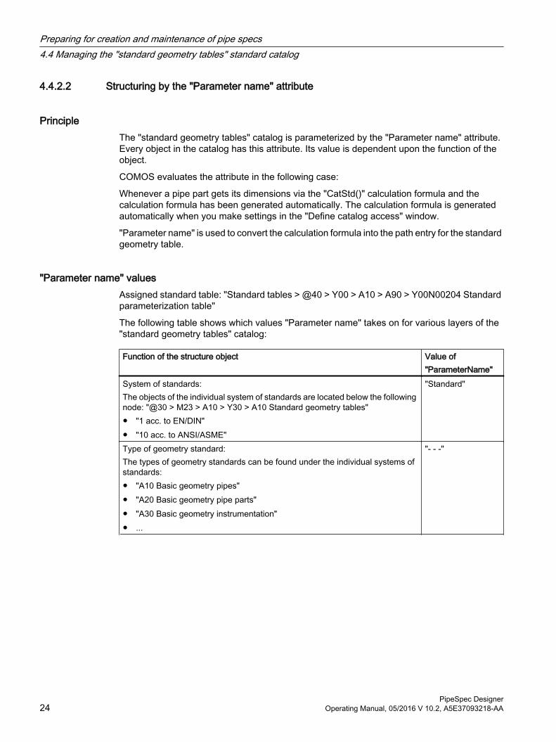
The following table shows which values "Parameter name" takes on for various layers of the "standard geometry tables" catalog:
Function of the structure object Value of "ParameterName"
System of standards:The objects of the individual system of standards are located below the following node: "@30 > M23 > A10 > Y30 > A10 Standard geometry tables"● "1 acc. to EN/DIN"● "10 acc. to ANSI/ASME"
"Standard"
Type of geometry standard:The types of geometry standards can be found under the individual systems of standards:● "A10 Basic geometry pipes"● "A20 Basic geometry pipe parts"● "A30 Basic geometry instrumentation"● ...
"- - -"
Preparing for creation and maintenance of pipe specs4.4 Managing the "standard geometry tables" standard catalog
PipeSpec Designer24 Operating Manual, 05/2016 V 10.2, A5E37093218-AA
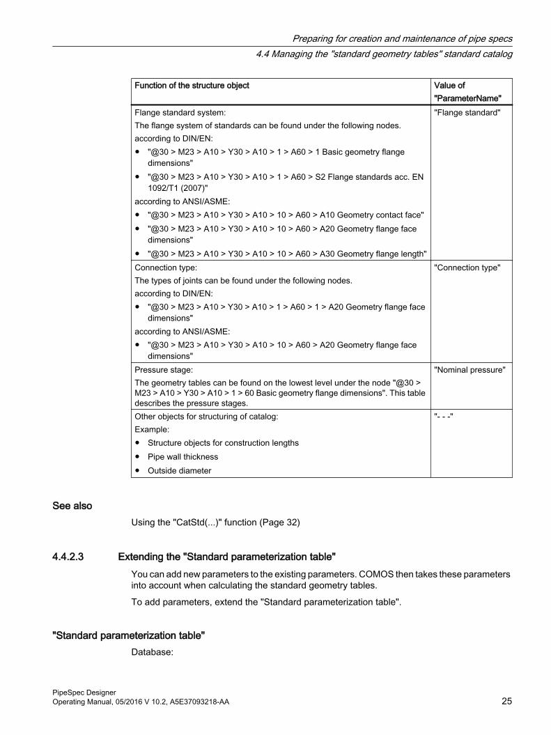
Function of the structure object Value of "ParameterName"
Flange standard system:The flange system of standards can be found under the following nodes.according to DIN/EN:● "@30 > M23 > A10 > Y30 > A10 > 1 > A60 > 1 Basic geometry flange
dimensions"● "@30 > M23 > A10 > Y30 > A10 > 1 > A60 > S2 Flange standards acc. EN
1092/T1 (2007)"according to ANSI/ASME:● "@30 > M23 > A10 > Y30 > A10 > 10 > A60 > A10 Geometry contact face"● "@30 > M23 > A10 > Y30 > A10 > 10 > A60 > A20 Geometry flange face
dimensions"● "@30 > M23 > A10 > Y30 > A10 > 10 > A60 > A30 Geometry flange length"
"Flange standard"
Connection type:The types of joints can be found under the following nodes.according to DIN/EN:● "@30 > M23 > A10 > Y30 > A10 > 1 > A60 > 1 > A20 Geometry flange face
dimensions"according to ANSI/ASME:● "@30 > M23 > A10 > Y30 > A10 > 10 > A60 > A20 Geometry flange face
dimensions"
"Connection type"
Pressure stage:The geometry tables can be found on the lowest level under the node "@30 > M23 > A10 > Y30 > A10 > 1 > 60 Basic geometry flange dimensions". This table describes the pressure stages.
"Nominal pressure"
Other objects for structuring of catalog:Example:● Structure objects for construction lengths● Pipe wall thickness● Outside diameter
"- - -"
See alsoUsing the "CatStd(...)" function (Page 32)
4.4.2.3 Extending the "Standard parameterization table"You can add new parameters to the existing parameters. COMOS then takes these parameters into account when calculating the standard geometry tables.
To add parameters, extend the "Standard parameterization table".
"Standard parameterization table"Database:
Preparing for creation and maintenance of pipe specs4.4 Managing the "standard geometry tables" standard catalog
PipeSpec DesignerOperating Manual, 05/2016 V 10.2, A5E37093218-AA 25
"Standard tables > @40 > Y00 > A10 > A90 > Y00N00204 Standard parameterization table"
Purpose:
● Is used to parameterize the "standard geometry tables" standard catalog
● Is assigned to the following attribute at the objects in the standard catalog: "Y00T00055.Y00A00027 Parameter name"
Structure:
● "Name":Continuous counter
● "Description":Describes the function that the object has in the "standard geometry tables" standard catalog.
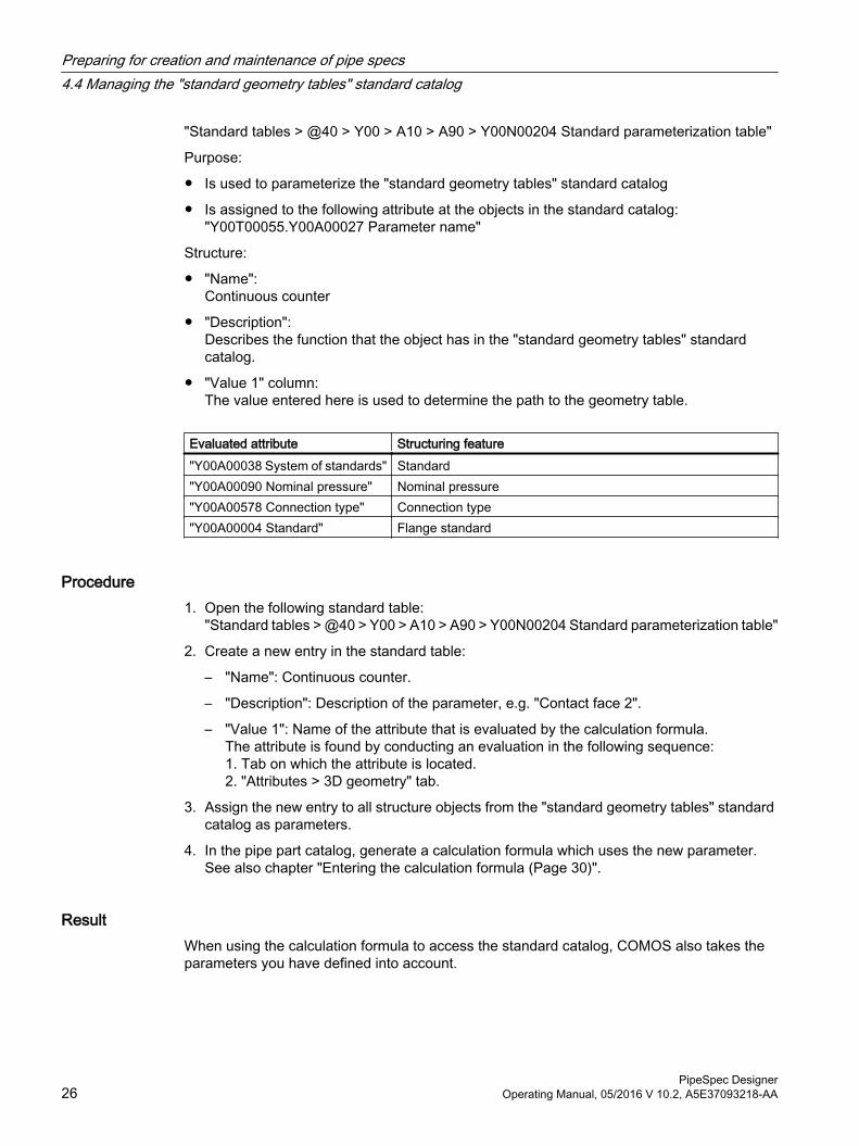
● "Value 1" column:The value entered here is used to determine the path to the geometry table.
Evaluated attribute Structuring feature"Y00A00038 System of standards" Standard"Y00A00090 Nominal pressure" Nominal pressure"Y00A00578 Connection type" Connection type"Y00A00004 Standard" Flange standard
Procedure1. Open the following standard table:
"Standard tables > @40 > Y00 > A10 > A90 > Y00N00204 Standard parameterization table"
2. Create a new entry in the standard table:
– "Name": Continuous counter.
– "Description": Description of the parameter, e.g. "Contact face 2".
– "Value 1": Name of the attribute that is evaluated by the calculation formula.The attribute is found by conducting an evaluation in the following sequence:1. Tab on which the attribute is located.2. "Attributes > 3D geometry" tab.
3. Assign the new entry to all structure objects from the "standard geometry tables" standard catalog as parameters.
4. In the pipe part catalog, generate a calculation formula which uses the new parameter.See also chapter "Entering the calculation formula (Page 30)".
ResultWhen using the calculation formula to access the standard catalog, COMOS also takes the parameters you have defined into account.
Preparing for creation and maintenance of pipe specs4.4 Managing the "standard geometry tables" standard catalog
PipeSpec Designer26 Operating Manual, 05/2016 V 10.2, A5E37093218-AA
See alsoStructuring by the "Parameter name" attribute (Page 24)
4.5 Administering pipe part catalogs
OverviewThe database is supplied with the pipe part catalog. The catalogs are located in the node:
"@50 > A10 > A10 > A10 Pipe part catalog"
The catalogs are nominal-diameter-independent. The nominal-diameter-dependent values are parameterized so that one base object bundles the characteristics for all nominal diameters.
Once a user assigns a nominal diameter to a part, the values dependent on the nominal diameter are entered in the engineering data.
Use of pipe part catalogs● 3D Integration
● Isometrics
● P&ID
4.5.1 Structure of the pipe part catalogsThe pipe part catalogs are managed separately according to the system of standards. The database is already populated with catalogs based on the DIN/EN and ANSI/ASME systems of standards.
The pipe part catalogs have the following basic structure:
System of standards > Pipe part type > Connection type > Material > Pipe parts
See alsoLegal notice (Page 9)
Preparing for creation and maintenance of pipe specs4.5 Administering pipe part catalogs
PipeSpec DesignerOperating Manual, 05/2016 V 10.2, A5E37093218-AA 27
4.5.2 Determining the component geometry of a pipe part
4.5.2.1 Configuring the geometry attributes
Principle● The base objects from the pipe part catalog are not multiplied out by nominal diameter.
They do not save the true values for the dimensions.
● The pipe part dimensions are determined in the properties of the pipe part."3D Geometry" tab, attributes of the following control groups:"General Geometric Description"
● Instead of actual dimensions, calculation formulae are input in the attributes in the base objects. The calculation formulae determine the following:
– The source from which the pipe part gets its dimensions
– How the actual values are calculated
– Which values are possible
● The calculation formulae are evaluated in the engineering data.Reason: Some attributes needed for the calculation are not set until the engineering data stage. For example, the construction angle or the component length for components with variable lengths.
Consequence:
If you create a pipe part in the engineering data and set the nominal diameter, COMOS evaluates the calculation formulae of the geometry attributes to determine which standard geometry tables should be used. Depending on which nominal diameter has been set at the
Preparing for creation and maintenance of pipe specs4.5 Administering pipe part catalogs
PipeSpec Designer28 Operating Manual, 05/2016 V 10.2, A5E37093218-AA
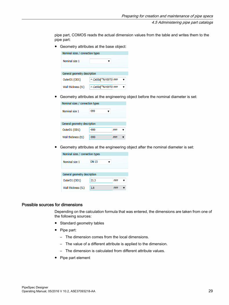
pipe part, COMOS reads the actual dimension values from the table and writes them to the pipe part:
● Geometry attributes at the base object:
● Geometry attributes at the engineering object before the nominal diameter is set:
● Geometry attributes at the engineering object after the nominal diameter is set:
Possible sources for dimensionsDepending on the calculation formula that was entered, the dimensions are taken from one of the following sources:
● Standard geometry tables
● Pipe part:
– The dimension comes from the local dimensions.
– The value of a different attribute is applied to the dimension.
– The dimension is calculated from different attribute values.
● Pipe part element
Preparing for creation and maintenance of pipe specs4.5 Administering pipe part catalogs
PipeSpec DesignerOperating Manual, 05/2016 V 10.2, A5E37093218-AA 29
● Local dimensions saved in the nominal-diameter-dependent characteristics table of the pipe spec
● A default value is defined for each calculation formula. It serves as the starting value in the engineering data.
Parameterized accessThe calculation formulae with "Cat" in their name read the dimension from a table. Their access to the table is parameterized via the nominal diameter: The value entered from the table in the geometry attribute depends upon the nominal diameter of the pipe part in the engineering data.
You can only define a parameter other than the nominal diameter in the case of "Cat2(...)".
See also"General geometry description" control group (Page 52)
Using the "Define catalog access" window (Page 31)
4.5.2.2 Entering the calculation formulaThe calculation formula consists of a function name and multiple items.
In addition, you can adapt the mathematical function to the result of the function.
Example: = Cat("Y00A00035", "Y00T00011.Y00A00003AA01" ) / 2
Attributes with calculation formulaAt the pipe part catalog base objects, the calculation formulae are used for attributes, the values of which depend on one or several nominal diameters.
Example: "Outer diameter".
These attributes must fulfill the following conditions:
● They are placed on the "3D geometry" tab or one of the "Connector <1-n>" tabs.
● The "3D" value is selected on the "Link" tab in the "Mode" list in the properties of the attribute.
Entering the calculation formulaYou have the following options to enter a calculation formula:
● Via the "Define catalog access" windowThe software generates a calculation formula from your inputs and writes it to the geometry attribute automatically.See chapter Using the "Define catalog access" window (Page 31).
● Manually
Preparing for creation and maintenance of pipe specs4.5 Administering pipe part catalogs
PipeSpec Designer30 Operating Manual, 05/2016 V 10.2, A5E37093218-AA
4.5.2.3 Using the "Define catalog access" windowIn the "Define catalog access" window, define the calculation formula for selected attributes. See also chapter Entering the calculation formula (Page 30).
ProcedureTo define the calculation formula using "Define catalog access", proceed as follows:
1. Open the properties of a base object in the pipe part catalog.
2. Select the "3D geometry" tab or one of the "Connector <1-n>" tabs.
3. Place the cursor into the text field of an attribute and press the "F2" key.The attribute must meet the following condition:The "3D" value is selected on the "Link" tab in the "Mode" list in the properties of the attribute.Example:
– "Wall thickness (t1)"
– "Insulation thickness"
4. Select the calculation formula in the "Function" field.
5. Define the parameters of the calculation formula.See also chapter Overview of the calculation formulae (Page 31).You can find detailed information about the calculation formulae in the following chapters:
– Using the "CatStd(...)" function (Page 32)
– Using the "Cat(...)" function (Page 36)
– Using the "Cat2(...)" function (Page 36)
– Using the "S(...)" function (Page 37)
– Using the "ElmS(...)" function (Page 37)
– Using the "CatPC(...)" function (Page 39)
– Using the "CatExt(...)" function (Page 38)
– "Def(...)" function (Page 39)
6. Save your entries.
4.5.2.4 Overview of the calculation formulae
"CatStd(...)" The value is taken from the standard catalog. It is determined based on the nominal diameter parameter.
"Cat(...)" The value is taken from the local dimensions defined at the pipe part. It is determined based on the nominal diameter parameter.
"Cat2(...)" The value is taken from a pipe part table you specify. It is determined based on a parameter you define.
"S(...)" The value of the pipe part attribute you specify is applied to the geometry attribute."ElmS(...)" Like "S()", but the attribute comes from an element of the pipe part."CatExt(...)" The value is taken from a pipe part table you specify. It is determined based on the
nominal diameter parameter.
Preparing for creation and maintenance of pipe specs4.5 Administering pipe part catalogs
PipeSpec DesignerOperating Manual, 05/2016 V 10.2, A5E37093218-AA 31
"CatPC(...)" The value is taken from the local dimensions defined in the pipe spec. It is determined based on the nominal diameter parameter.
"Def(...)" Sets a default value that is used as the starting value in the engineering data.
4.5.2.5 Using the "CatStd(...)" functionThe function expects the parameters 1-3. Optional: Parameter 4.
See also chapter Using the "Define catalog access" window (Page 31).
Every component of the first element is either made up of a fixed value or a variable. For every object under the "standard geometry tables" node, COMOS evaluates which value the attribute "Y00T00055.Y00A00027 Parameter name" has, and compiles the calculation formula from this.
An element of the calculation formula is marked as a variable value depending on the value in the attribute "Parameter name":
● Value of "Parameter name" is equal to "- - -":The name of the object is added to the formula (fixed value).
● Value of "Parameter name" is not equal to "- - -":The name of the attribute corresponding to the entry set in "Parameter name" is added to the formula (variable). The name of the current tab is added to the name of the attribute. If the attribute does not have a value, the name of the "3D geometry" tab is used.The variables are enclosed in "%" characters. Example: "%Y00T00011.Y00A00038%"The variable is unlinked in the engineering data.
Requirements● You have opened the "Define catalog access" window for one of the fields of the "General
geometry description" control group. You have selected the "CatStd(...)" entry in the "Function" field.
● You have followed the naming system of the standard catalog.
Preparing for creation and maintenance of pipe specs4.5 Administering pipe part catalogs
PipeSpec Designer32 Operating Manual, 05/2016 V 10.2, A5E37093218-AA
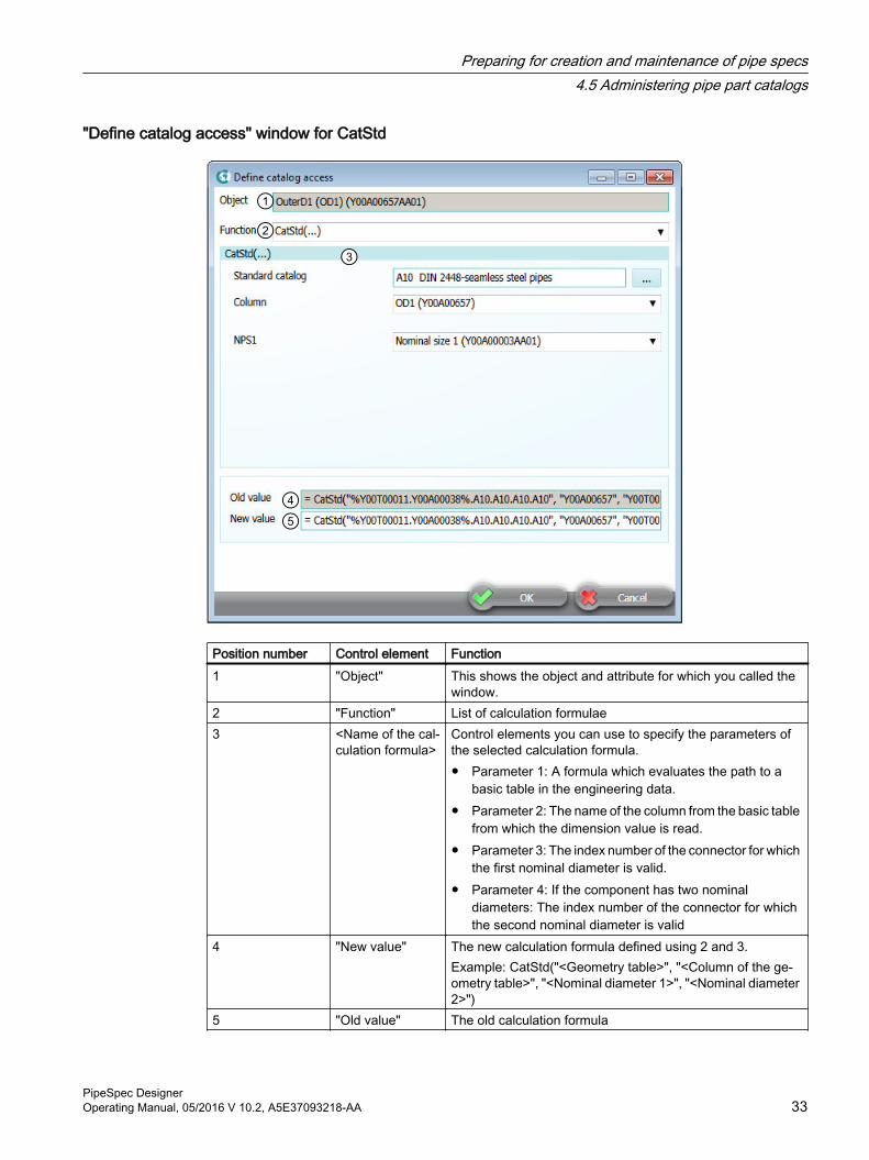
"Define catalog access" window for CatStd
Position number Control element Function1 "Object" This shows the object and attribute for which you called the
window.2 "Function" List of calculation formulae3 <Name of the cal‐
culation formula>Control elements you can use to specify the parameters of the selected calculation formula.● Parameter 1: A formula which evaluates the path to a
basic table in the engineering data.● Parameter 2: The name of the column from the basic table
from which the dimension value is read.● Parameter 3: The index number of the connector for which
the first nominal diameter is valid.● Parameter 4: If the component has two nominal
diameters: The index number of the connector for which the second nominal diameter is valid
4 "New value" The new calculation formula defined using 2 and 3.Example: CatStd("<Geometry table>", "<Column of the ge‐ometry table>", "<Nominal diameter 1>", "<Nominal diameter 2>")
5 "Old value" The old calculation formula
Preparing for creation and maintenance of pipe specs4.5 Administering pipe part catalogs
PipeSpec DesignerOperating Manual, 05/2016 V 10.2, A5E37093218-AA 33
Procedure1. In the "Define catalog access" window, click the "..." button next to the "Standard catalog"
field.The "Catalog selection" window opens. You can see the "standard geometry tables" catalog.
2. Navigate through the structure objects of the catalog until you reach a geometry table.
3. Select the geometry table and click the "OK" button.
Note
By selecting a standard geometry table, you define a formula. The formula is evaluated in the engineering data at the pipe part and returns the path to a standard geometry table.
Although you select an actual standard geometry table, the formula does not necessarily calculate the table you have selected in the engineering data.
4. In the "Column" field you specify from which column of the standard geometry table the dimension value is read.
5. In the field "NPS1" and optionally in the field "NSP2", specify for which component connector the value is valid.
6. Click the "OK" button.
Message "Error in catalog selection"COMOS checks the path entry when you close the "Catalog selection" window. If COMOS does not find a standard geometry table in the location specified by the path, the "Error in catalog selection" window opens.
Here you decide if you want to apply the entries even though a table was not found.
NoteIncorrect path can be correct in the engineering project
When selecting the path in an engineering project, other values can exist which result in a valid catalog selection.
Reasons:● Not all relevant attributes have yet been set at the base object.● Different attribute values may be set at the engineering object than at the base object.
Preparing for creation and maintenance of pipe specs4.5 Administering pipe part catalogs
PipeSpec Designer34 Operating Manual, 05/2016 V 10.2, A5E37093218-AA
"CatStd(...)" in the engineering data"CatStd(...)" is executed as follows in the engineering data:
1. COMOS reads the current nominal diameter of the pipe part from the attribute: "Y00T00011.Y00A00003AA01 Nominal diameter 1".
2. COMOS evaluates the formula provided in parameter 1:
– The attributes behind the variables in the calculation formula are evaluated at the pipe part.
– They are combined with the fixed values to create a string ‑ the path to the standard geometry table to be used.
3. COMOS goes from the standard geometry table specified by parameter 1 to the column specified by parameter 2, from where it retrieves the dimension of the nominal diameter set at the pipe part.
4. COMOS writes this value to the dimension attribute.
ExampleThe following calculation formula is entered in the "OutD1 (OD1)" attribute at the base object of a weld neck flange: =CatStd("%Y00T00011.Y00A00038%.A10.A10.A20.A10", "Y00A00657", "Y00T00011.Y00A00003AA01" )
1. COMOS calculates the current nominal diameter of the flange.
2. COMOS replaces the "%Y00T00011.Y00A00038%" variable in the calculation formula with the value of the "%Y00T00011.Y00A00038%" attribute in the engineering data at the flange:
– Variable: "%Y00T00011.Y00A00038%"
– DisplayValue: "EN/DIN Metric"
– Value "Y00T00011.Y00A00038%": "1"
COMOS compiles the path to the standard geometry table:"@30 > M23 > A10 > Y30 > A10 > 1 > A10 > A10 > A20 > A10 Seamless and welded steel pipes according to EN 10220"
3. COMOS takes the value entered for the current nominal diameter from column "D1 (Y00A00657)" and writes it to the "OutD1 (AD)" attribute.
Entering the calculation formula manuallyIf you enter the calculation formula manually, you are free to decide where a variable is used and where a fixed name is used in parameter 1.
See alsoConfiguring the geometry attributes (Page 28)
Structuring by the "Parameter name" attribute (Page 24)
Extending the "Standard parameterization table" (Page 25)
Preparing for creation and maintenance of pipe specs4.5 Administering pipe part catalogs
PipeSpec DesignerOperating Manual, 05/2016 V 10.2, A5E37093218-AA 35
4.5.2.6 Using the "Cat(...)" function
Functional principle of "Cat(...)"● In the engineering view, the dimension value is taken from the local dimensions that are
maintained at the pipe part: Properties of the component, "Local Dimensions" tab, "Y00A00567 Nominal-diameter-dependent table"
● The value is determined based on the nominal diameter parameter.
RequirementYou have selected the "Cat(...)" function in the "Function" field of the "Define catalog access" window.
Procedure1. "Column" field: Specify from which column of the nominal-diameter-dependent table the
value is read.
2. "Nominal diameter of connector" and "2. Nominal diameter of connector" fields: Specify for which component connector the value is valid.If the pipe part has only one nominal diameter: Select "Ignore" for "2. Nominal diameter of connector".
3. Click the "OK" button.
4.5.2.7 Using the "Cat2(...)" function
Functional principle of "Cat2(...)"● The "Cat2(...)" function reads the dimension value from a pipe part table you specify.
● The value is determined based on the parameter you define.
RequirementYou have selected the "Cat2(...)" function in the "Function" field of the "Define catalog access" window.
Procedure1. Click the "..." button next to the "Table" field.
The "Catalog selection" window opens. You see the base object of the pipe part and its tabs.
2. Select the required table and click the "OK" button.
3. "Result column" field: Specify from which column of the table the dimension value is read.
4. "Search column 1" field: Specify the column to be used as the search parameter.
Preparing for creation and maintenance of pipe specs4.5 Administering pipe part catalogs
PipeSpec Designer36 Operating Manual, 05/2016 V 10.2, A5E37093218-AA
5. For pipe parts with two nominal diameters: Specify the column of the second search parameter in the "Search parameter 2" field.
6. "1st attribute with search value" field: Specify which attribute of the pipe part is evaluated to find the correct search row in the search column.
7. "2nd attribute with search value" field: For pipe parts with two nominal diameters. Same as above.
8. Click the "OK" button.
4.5.2.8 Using the "S(...)" function
Functional principle of "S(...)"The "S(...)" function uses the value from another pipe part attribute as the dimension.
RequirementYou have selected the "S(...)" function in the "Function" field of the "Define catalog access" window.
Procedure1. "Specification" field: Click the "..." button next to the field.
The "Attribute selection" window opens. You see the base object of the pipe part and its tabs.
2. Select the required attribute and click the "OK" button.
3. In the "Define catalog access" window, click the "OK" button.
4.5.2.9 Using the "ElmS(...)" function
Functional principle of "ElmS(...)"The "ElmS(...)" function uses the value from an attribute of a pipe part element as the dimension.
RequirementYou have selected the "ElmS(...)" function in the "Function" field of the "Define catalog access" window.
Preparing for creation and maintenance of pipe specs4.5 Administering pipe part catalogs
PipeSpec DesignerOperating Manual, 05/2016 V 10.2, A5E37093218-AA 37
Procedure1. "Element" field: Click the "..." button next to the field.
The "Element selection" window opens. You see the base object of the pipe part and the subordinate elements.
2. Select the required element and click the "OK" button.
3. "Specification" field: Click the "..." button next to the field.The "Attribute selection" window opens. You see the base object of the element and its tabs and attributes.
4. Select the required attribute.
5. In the "Define catalog access" window, click the "OK" button.
See alsoUsing the "S(...)" function (Page 37)
4.5.2.10 Using the "CatExt(...)" function
Functional principle of "CatExt(...)"● The dimension is read at the pipe part from a table you specify.
● The value is determined based on the nominal diameter parameter.
RequirementYou have selected the "CatExt(...)" function in the "Function" field of the "Define catalog access" window.
Procedure1. "Table" field: Click the "..." button next to the field.
The "Catalog selection" window opens. You see the base object of the pipe part and its tabs.
2. Select the required table and click the "OK" button.
3. Continue as described for the "Cat(...)" function. See chapter Using the "Cat(...)" function (Page 36).
4. Click the "OK" button.
Preparing for creation and maintenance of pipe specs4.5 Administering pipe part catalogs
PipeSpec Designer38 Operating Manual, 05/2016 V 10.2, A5E37093218-AA
4.5.2.11 Using the "CatPC(...)" function
Functional principle of "CatPC(...)"● The dimensions are read from the local deviations entered in the pipe spec:
"Characteristics" tab, "Y00A00125 Geometry row" table
● The value is determined based on the nominal diameter parameter.
Requirement● You have selected the "CatPC(...)" function in the "Function" field of the "Define catalog
access" window.
● The pipe part is assigned to a pipe spec.
Procedure1. Click the "..." button to the right of the "Pipe spec" field.
The "Element selection" window opens.
2. Select a pipe spec and click "OK".
3. "Column" field: Specify which column the value is taken from.
4. In the "1st nominal diameter" and "2nd nominal diameter" fields, specify the component connector for which the value is valid.If the pipe part has only one nominal diameter: Select "Ignore" for "2nd nominal diameter".
5. Click the "OK" button.
4.5.2.12 "Def(...)" functionYou can only input the "Def(...)" calculation formula manually.
ProcedurePass a value as a parameter that serves as the starting value and can be replaced by another value at a later stage in the engineering data.
Example:
Def(2500)
ResultIf the base object is changed in the engineering data, the attribute value that was input at the pipe part is always retained.
In contrast, if you input the starting value directly into the attribute in the base data, when the base object is changed, the attribute value input at the object is replaced by the value defined at the new base object.
Preparing for creation and maintenance of pipe specs4.5 Administering pipe part catalogs
PipeSpec DesignerOperating Manual, 05/2016 V 10.2, A5E37093218-AA 39
4.5.3 Nominal diameter range of a pipe part
4.5.3.1 Introduction to nominal diameter rangesThe base objects of the pipe parts from the pipe part catalog are almost completely specified templates that are parameterized according to nominal diameter. Only by setting the nominal diameter can a manufacturer device be assigned to a base object.
A nominal diameter can only be assigned to a manufacturer device if it lies in the nominal diameter range of the pipe part.
COMOS validates the permitted nominal diameter ranges of a pipe part and saves them at the corresponding object. Regarding the nominal diameter, a pipe part counts as permitted when the following requirement is met:
The values that are relevant for calculating the geometry have to be calculable. The relevant values depend on the type of the pipe part.
The calculated nominal diameter range is saved at the pipe part as an XML string in the "Y00A04288 Nominal diameter range" attribute on the "3D geometry" tab.
The nominal diameter range of a pipe part can also be displayed on the user interface. See also chapter Display nominal diameter range (Page 40).
For pipe-spec-dependent pipe parts for which the function "CatPC" has been set, the XML string is created underneath the pipe spec element.
4.5.3.2 Display nominal diameter rangeThe pipe parts in the pipe part catalog are configured in such a way that you can read the nominal diameter range on the ""Display for nominal diameter range"" tab.
If you create a new pipe part type in the template of the pipe part catalog under the node "@30 > M23 > A50 > A10 > A10 > A10 Pipe part catalog template", you must link the "Y00T00057 Display for nominal diameter range" tab.
Procedure1. Open the "Attributes" tab in the properties of the new object.
2. Go to design mode.
3. Create a new tab.
4. Set the following tab as catalog tab:"@40 > A20 > Y00 > A10 > A30 > Y00T00057 > A01 > Y00T00057 display for nominal diameter range"
5. Confirm your entries.
See also"Display for nominal diameter range" tab (Page 53)
Preparing for creation and maintenance of pipe specs4.5 Administering pipe part catalogs
PipeSpec Designer40 Operating Manual, 05/2016 V 10.2, A5E37093218-AA
4.5.3.3 New calculation of the nominal diameter rangeYou must recalculate the nominal diameter range in the following cases:
● If changes are made to the attributes of a pipe part which affect its nominal diameter range.This is necessary when you make changes to the following positions:
– "3D geometry" tab
– "Connection <1-n>" tabs
● When you make changes to the standard geometry tables on which the pipe part depends.
RequirementYou have opened the "Attributes > Display for nominal diameter range" tab for the changed pipe part.
ProcedureClick the "Refresh" button to recalculate the nominal diameter range.
Note
Clicking the "Refresh" button to recalculate the nominal diameter range overwrites all manual changes you have made to the nominal diameter range in the table.
Problems with missing rightsThe nominal diameter range may not be saved in the "Y00A04288 Nominal diameter range" attribute. Examples of possible reasons:
● Missing rights
● They are located in another project
In this case the XML string is not available; it is recalculated every time it is needed. See also chapter Integration into existing databases (Page 42).
4.5.3.4 Restricting the nominal diameter range of a pipe part
RequirementYou have opened the "Display for nominal diameter range" tab.
Preparing for creation and maintenance of pipe specs4.5 Administering pipe part catalogs
PipeSpec DesignerOperating Manual, 05/2016 V 10.2, A5E37093218-AA 41
Procedure1. To exclude nominal diameters from or add them to the nominal diameter range, click once
with the left mouse button in a cell.You can only edit the cells in which a check box is displayed.
– Option deactivated. The nominal diameter is not in the nominal diameter range.
– Option activated. The nominal diameter is in the nominal diameter range.
2. Save your entries.
Result● You have defined the nominal diameter range in which the pipe part is available.
● The nominal diameter range is saved at the pipe part as an XML string in the "Y00A04288 Nominal diameter range" attribute.
See also"Display for nominal diameter range" tab (Page 53)
4.5.3.5 Integration into existing databasesIf you are already working with an existing database and the "Y00A04288 nominal diameter range" attribute and associated XML strings have not yet been generated for its pipe part base objects, you should convert the base objects of the pipe parts once only.
If you do not convert the base objects in the base project, COMOS cannot create the attribute in the engineering data. The permitted nominal diameter range must always be recalculated every time it is called. This can lead to a decrease in performance.
Note
The time taken to complete the conversion depends upon the number of pipe parts. Run the conversion overnight if necessary.
Script for conversionTo run the conversion, implement the following script at the structure object of the pipe part catalog or execute it via the object debugger:"Set Checklib = CreateObject ("ComosPPCObjectCheck.Lib")CheckLib.NDRangeForCDevice Me,Nothing"Me" is equivalent to the start object.
The conversion is conducted recursively.
Preparing for creation and maintenance of pipe specs4.5 Administering pipe part catalogs
PipeSpec Designer42 Operating Manual, 05/2016 V 10.2, A5E37093218-AA
4.5.4 Extending a pipe part catalog
4.5.4.1 Creating a new catalogThe database contains two pipe part catalogs: One catalog based on DIN/EN standards and one catalog based on the ANSI/ASME standards.
You can create more catalogs, e.g. manufacturer catalogs.
RequirementThe system of standards on which the new catalog is to be based already exists in the database.
If not: See chapter Creating a new system of standards (Page 55).
Procedure1. Navigate to the following node:
Example: "@50 > A10 > A10 > A10 Pipe part catalog"
2. Dependent upon the extent to which the new catalog differs from existing catalogs, create it from scratch or copy and change an existing catalog:
– New catalog:Use the following templates as a basis for the new catalog:"@30 > M23 > A50 > A10 > A10 > A10 Pipe part catalog template"
– Copied catalog:Select the "Copy structure" command from the context menu.The structure is created parallel to the selected object. It contains the suffix "_1".
3. Enter the description of the new pipe part catalog.
4. Select the system of standards on the pipe parts on the "Attributes > Part description" tab in the "System of standards" attribute.
5. In order to apply the value to all "System of standards" attributes of the object, click on the "Update attributes" button.Hint: Change the bulk processing in order to change the system of standards at all objects. You can find additional information on this topic in the "Administration" manual, keyword "Bulk processing". The standard tables at the attributes of the pipe part objects are switched by the shift in the system of standards.
6. Complete the substructure of the catalog. Dependent upon whether the catalog is completely new or based on a copy, proceed as follows:
– New catalog: Create the substructure of the catalog as far as the actual pipe parts.
– Copied catalog: Rename nodes, create new nodes, edit the properties, or delete nodes (e.g. nodes for pipe part types which are not produced by the manufacturer), if necessary.
Preparing for creation and maintenance of pipe specs4.5 Administering pipe part catalogs
PipeSpec DesignerOperating Manual, 05/2016 V 10.2, A5E37093218-AA 43
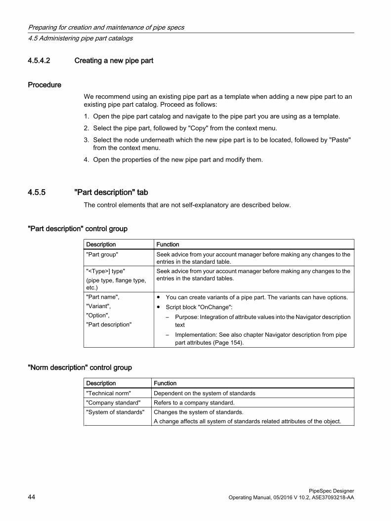
4.5.4.2 Creating a new pipe part
ProcedureWe recommend using an existing pipe part as a template when adding a new pipe part to an existing pipe part catalog. Proceed as follows:
1. Open the pipe part catalog and navigate to the pipe part you are using as a template.
2. Select the pipe part, followed by "Copy" from the context menu.
3. Select the node underneath which the new pipe part is to be located, followed by "Paste" from the context menu.
4. Open the properties of the new pipe part and modify them.
4.5.5 "Part description" tabThe control elements that are not self-explanatory are described below.
"Part description" control group
Description Function"Part group" Seek advice from your account manager before making any changes to the
entries in the standard table."<Type>] type" (pipe type, flange type, etc.)
Seek advice from your account manager before making any changes to the entries in the standard tables.
"Part name","Variant", "Option", "Part description"
● You can create variants of a pipe part. The variants can have options.● Script block "OnChange":
– Purpose: Integration of attribute values into the Navigator description text
– Implementation: See also chapter Navigator description from pipe part attributes (Page 154).
"Norm description" control group
Description Function"Technical norm" Dependent on the system of standards"Company standard" Refers to a company standard."System of standards" Changes the system of standards.
A change affects all system of standards related attributes of the object.
Preparing for creation and maintenance of pipe specs4.5 Administering pipe part catalogs
PipeSpec Designer44 Operating Manual, 05/2016 V 10.2, A5E37093218-AA
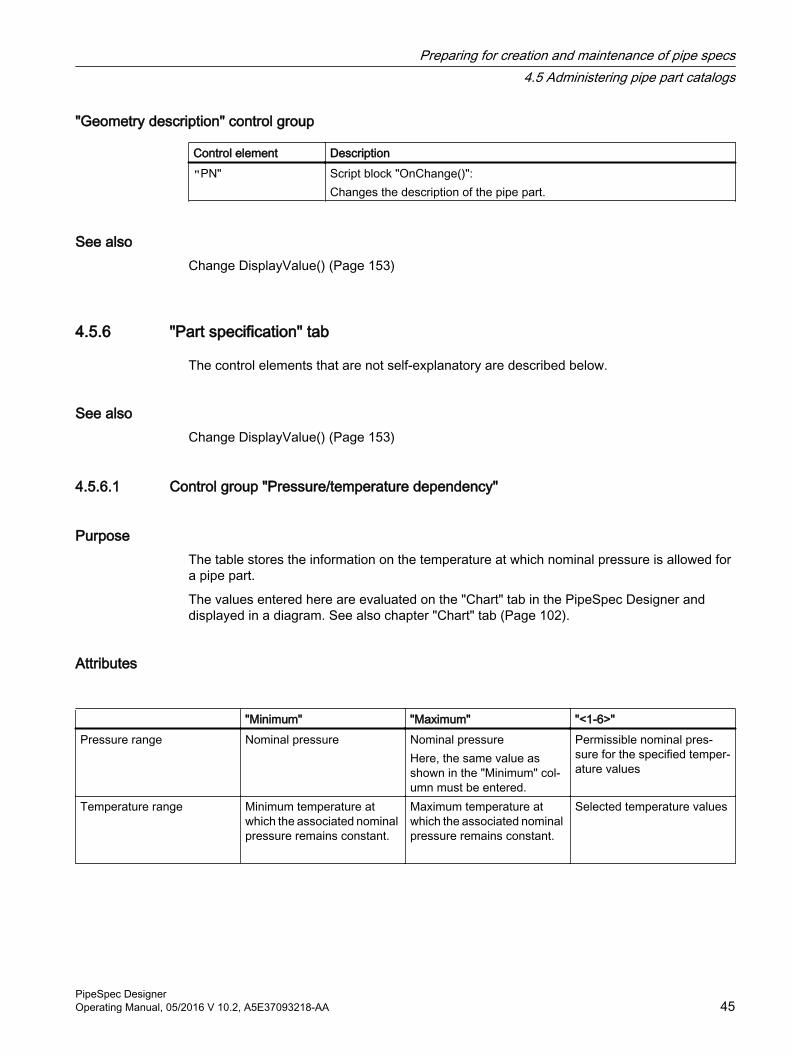
"Geometry description" control group
Control element Description "PN" Script block "OnChange()":
Changes the description of the pipe part.
See alsoChange DisplayValue() (Page 153)
4.5.6 "Part specification" tab
The control elements that are not self-explanatory are described below.
See alsoChange DisplayValue() (Page 153)
4.5.6.1 Control group "Pressure/temperature dependency"
PurposeThe table stores the information on the temperature at which nominal pressure is allowed for a pipe part.
The values entered here are evaluated on the "Chart" tab in the PipeSpec Designer and displayed in a diagram. See also chapter "Chart" tab (Page 102).
Attributes
"Minimum" "Maximum" "<1-6>"Pressure range Nominal pressure Nominal pressure
Here, the same value as shown in the "Minimum" col‐umn must be entered.
Permissible nominal pres‐sure for the specified temper‐ature values
Temperature range Minimum temperature at which the associated nominal pressure remains constant.
Maximum temperature at which the associated nominal pressure remains constant.
Selected temperature values
Preparing for creation and maintenance of pipe specs4.5 Administering pipe part catalogs
PipeSpec DesignerOperating Manual, 05/2016 V 10.2, A5E37093218-AA 45
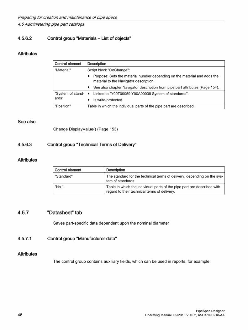
4.5.6.2 Control group "Materials – List of objects"
Attributes
Control element Description "Material" Script block "OnChange":
● Purpose: Sets the material number depending on the material and adds the material to the Navigator description.
● See also chapter Navigator description from pipe part attributes (Page 154)."System of stand‐ards"
● Linked to "Y00T00059.Y00A00038 System of standards".● Is write-protected
"Position" Table in which the individual parts of the pipe part are described.
See alsoChange DisplayValue() (Page 153)
4.5.6.3 Control group "Technical Terms of Delivery"
Attributes
Control element Description"Standard" The standard for the technical terms of delivery, depending on the sys‐
tem of standards"No." Table in which the individual parts of the pipe part are described with
regard to their technical terms of delivery.
4.5.7 "Datasheet" tab
Saves part-specific data dependent upon the nominal diameter
4.5.7.1 Control group "Manufacturer data"
AttributesThe control group contains auxiliary fields, which can be used in reports, for example:
Preparing for creation and maintenance of pipe specs4.5 Administering pipe part catalogs
PipeSpec Designer46 Operating Manual, 05/2016 V 10.2, A5E37093218-AA
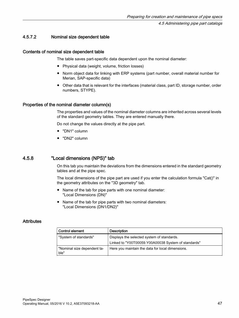
4.5.7.2 Nominal size dependent table
Contents of nominal size dependent table The table saves part-specific data dependent upon the nominal diameter:
● Physical data (weight, volume, friction losses)
● Norm object data for linking with ERP systems (part number, overall material number for Merian, SAP-specific data)
● Other data that is relevant for the interfaces (material class, part ID, storage number, order numbers, STYPE).
Properties of the nominal diameter column(s)The properties and values of the nominal diameter columns are inherited across several levels of the standard geometry tables. They are entered manually there.
Do not change the values directly at the pipe part.
● "DN1" column
● "DN2" column
4.5.8 "Local dimensions (NPS)" tabOn this tab you maintain the deviations from the dimensions entered in the standard geometry tables and at the pipe spec.
The local dimensions of the pipe part are used if you enter the calculation formula "Cat()" in the geometry attributes on the "3D geometry" tab.
● Name of the tab for pipe parts with one nominal diameter:"Local Dimensions (DN)"
● Name of the tab for pipe parts with two nominal diameters:"Local Dimensions (DN1/DN2)"
Attributes
Control element Description"System of standards" Displays the selected system of standards.
Linked to "Y00T00059.Y00A00038 System of standards""Nominal size dependent ta‐ble"
Here you maintain the data for local dimensions.
Preparing for creation and maintenance of pipe specs4.5 Administering pipe part catalogs
PipeSpec DesignerOperating Manual, 05/2016 V 10.2, A5E37093218-AA 47
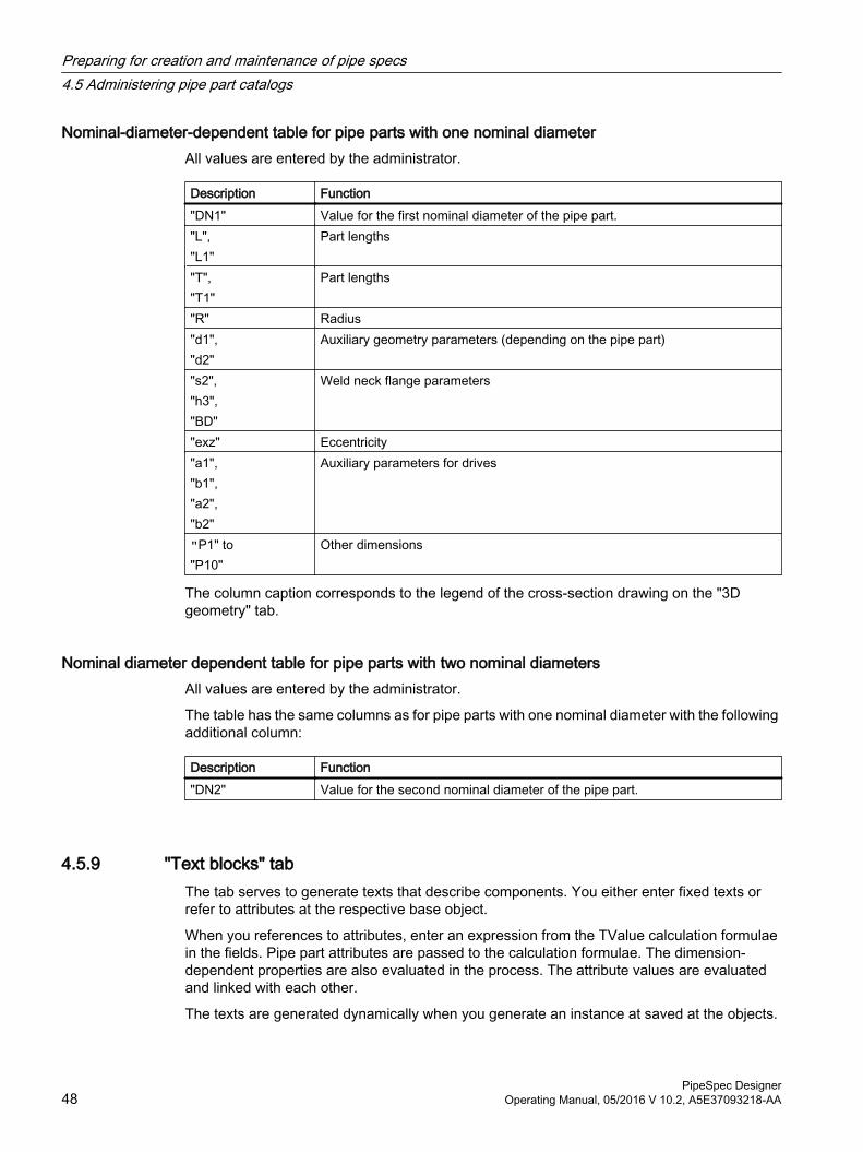
Nominal-diameter-dependent table for pipe parts with one nominal diameterAll values are entered by the administrator.
Description Function"DN1" Value for the first nominal diameter of the pipe part."L", "L1"
Part lengths
"T", "T1"
Part lengths
"R" Radius"d1", "d2"
Auxiliary geometry parameters (depending on the pipe part)
"s2", "h3", "BD"
Weld neck flange parameters
"exz" Eccentricity"a1", "b1", "a2", "b2"
Auxiliary parameters for drives
"P1" to"P10"
Other dimensions
The column caption corresponds to the legend of the cross-section drawing on the "3D geometry" tab.
Nominal diameter dependent table for pipe parts with two nominal diametersAll values are entered by the administrator.
The table has the same columns as for pipe parts with one nominal diameter with the following additional column:
Description Function"DN2" Value for the second nominal diameter of the pipe part.
4.5.9 "Text blocks" tabThe tab serves to generate texts that describe components. You either enter fixed texts or refer to attributes at the respective base object.
When you references to attributes, enter an expression from the TValue calculation formulae in the fields. Pipe part attributes are passed to the calculation formulae. The dimension-dependent properties are also evaluated in the process. The attribute values are evaluated and linked with each other.
The texts are generated dynamically when you generate an instance at saved at the objects.
Preparing for creation and maintenance of pipe specs4.5 Administering pipe part catalogs
PipeSpec Designer48 Operating Manual, 05/2016 V 10.2, A5E37093218-AA
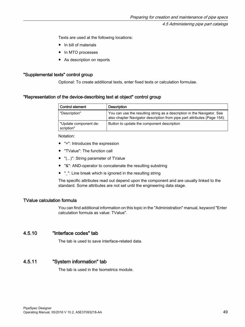
Texts are used at the following locations:
● In bill of materials
● In MTO processes
● As description on reports
"Supplemental texts" control groupOptional: To create additional texts, enter fixed texts or calculation formulae.
"Representation of the device-describing text at object" control group
Control element Description"Description" You can use the resulting string as a description in the Navigator. See
also chapter Navigator description from pipe part attributes (Page 154)."Update component de‐scription"
Button to update the component description
Notation:
● "=": Introduces the expression
● "TValue": The function call
● "(...)": String parameter of TValue
● "&": AND-operator to concatenate the resulting substring
● "_": Line break which is ignored in the resulting string
The specific attributes read out depend upon the component and are usually linked to the standard. Some attributes are not set until the engineering data stage.
TValue calculation formulaYou can find additional information on this topic in the "Administration" manual, keyword "Enter calculation formula as value: TValue".
4.5.10 "Interface codes" tabThe tab is used to save interface-related data.
4.5.11 "System information" tabThe tab is used in the Isometrics module.
Preparing for creation and maintenance of pipe specs4.5 Administering pipe part catalogs
PipeSpec DesignerOperating Manual, 05/2016 V 10.2, A5E37093218-AA 49
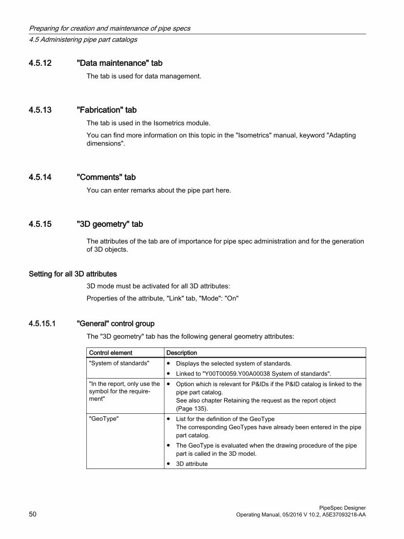
4.5.12 "Data maintenance" tabThe tab is used for data management.
4.5.13 "Fabrication" tabThe tab is used in the Isometrics module.
You can find more information on this topic in the "Isometrics" manual, keyword "Adapting dimensions".
4.5.14 "Comments" tabYou can enter remarks about the pipe part here.
4.5.15 "3D geometry" tab
The attributes of the tab are of importance for pipe spec administration and for the generation of 3D objects.
Setting for all 3D attributes3D mode must be activated for all 3D attributes:
Properties of the attribute, "Link" tab, "Mode": "On"
4.5.15.1 "General" control groupThe "3D geometry" tab has the following general geometry attributes:
Control element Description"System of standards" ● Displays the selected system of standards.
● Linked to "Y00T00059.Y00A00038 System of standards"."In the report, only use the symbol for the require‐ment"
● Option which is relevant for P&IDs if the P&ID catalog is linked to the pipe part catalog.See also chapter Retaining the request as the report object (Page 135).
"GeoType" ● List for the definition of the GeoTypeThe corresponding GeoTypes have already been entered in the pipe part catalog.
● The GeoType is evaluated when the drawing procedure of the pipe part is called in the 3D model.
● 3D attribute
Preparing for creation and maintenance of pipe specs4.5 Administering pipe part catalogs
PipeSpec Designer50 Operating Manual, 05/2016 V 10.2, A5E37093218-AA
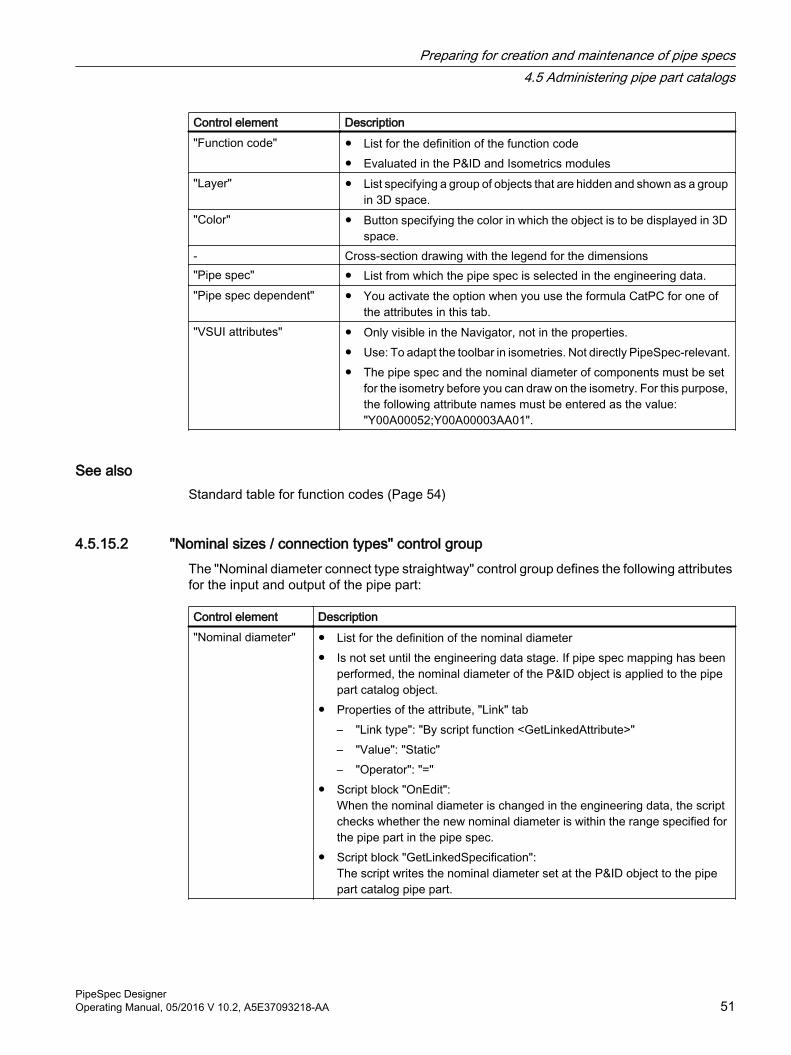
Control element Description"Function code" ● List for the definition of the function code
● Evaluated in the P&ID and Isometrics modules"Layer" ● List specifying a group of objects that are hidden and shown as a group
in 3D space."Color" ● Button specifying the color in which the object is to be displayed in 3D
space.- Cross-section drawing with the legend for the dimensions"Pipe spec" ● List from which the pipe spec is selected in the engineering data."Pipe spec dependent" ● You activate the option when you use the formula CatPC for one of
the attributes in this tab."VSUI attributes" ● Only visible in the Navigator, not in the properties.
● Use: To adapt the toolbar in isometries. Not directly PipeSpec-relevant.● The pipe spec and the nominal diameter of components must be set
for the isometry before you can draw on the isometry. For this purpose, the following attribute names must be entered as the value: "Y00A00052;Y00A00003AA01".
See alsoStandard table for function codes (Page 54)
4.5.15.2 "Nominal sizes / connection types" control groupThe "Nominal diameter connect type straightway" control group defines the following attributes for the input and output of the pipe part:
Control element Description"Nominal diameter" ● List for the definition of the nominal diameter
● Is not set until the engineering data stage. If pipe spec mapping has been performed, the nominal diameter of the P&ID object is applied to the pipe part catalog object.
● Properties of the attribute, "Link" tab– "Link type": "By script function <GetLinkedAttribute>"– "Value": "Static"– "Operator": "="
● Script block "OnEdit":When the nominal diameter is changed in the engineering data, the script checks whether the new nominal diameter is within the range specified for the pipe part in the pipe spec.
● Script block "GetLinkedSpecification":The script writes the nominal diameter set at the P&ID object to the pipe part catalog pipe part.
Preparing for creation and maintenance of pipe specs4.5 Administering pipe part catalogs
PipeSpec DesignerOperating Manual, 05/2016 V 10.2, A5E37093218-AA 51
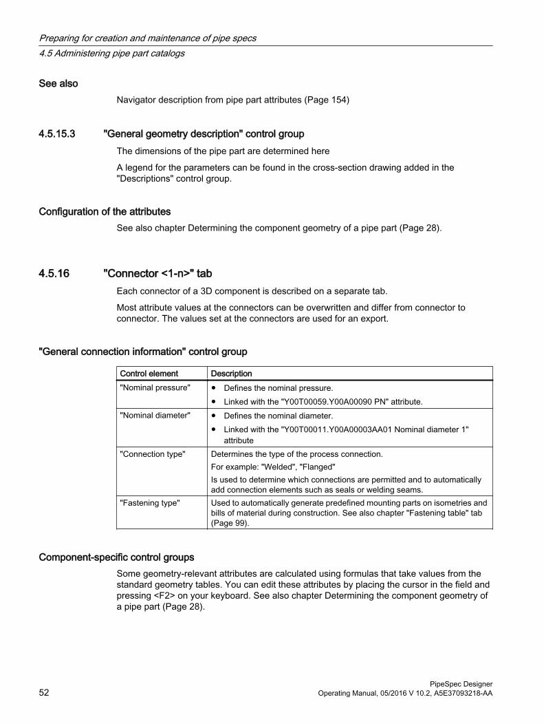
See alsoNavigator description from pipe part attributes (Page 154)
4.5.15.3 "General geometry description" control groupThe dimensions of the pipe part are determined here
A legend for the parameters can be found in the cross-section drawing added in the "Descriptions" control group.
Configuration of the attributesSee also chapter Determining the component geometry of a pipe part (Page 28).
4.5.16 "Connector <1-n>" tabEach connector of a 3D component is described on a separate tab.
Most attribute values at the connectors can be overwritten and differ from connector to connector. The values set at the connectors are used for an export.
"General connection information" control group
Control element Description"Nominal pressure" ● Defines the nominal pressure.
● Linked with the "Y00T00059.Y00A00090 PN" attribute."Nominal diameter" ● Defines the nominal diameter.
● Linked with the "Y00T00011.Y00A00003AA01 Nominal diameter 1" attribute
"Connection type" Determines the type of the process connection.For example: "Welded", "Flanged"Is used to determine which connections are permitted and to automatically add connection elements such as seals or welding seams.
"Fastening type" Used to automatically generate predefined mounting parts on isometries and bills of material during construction. See also chapter "Fastening table" tab (Page 99).
Component-specific control groupsSome geometry-relevant attributes are calculated using formulas that take values from the standard geometry tables. You can edit these attributes by placing the cursor in the field and pressing <F2> on your keyboard. See also chapter Determining the component geometry of a pipe part (Page 28).
Preparing for creation and maintenance of pipe specs4.5 Administering pipe part catalogs
PipeSpec Designer52 Operating Manual, 05/2016 V 10.2, A5E37093218-AA
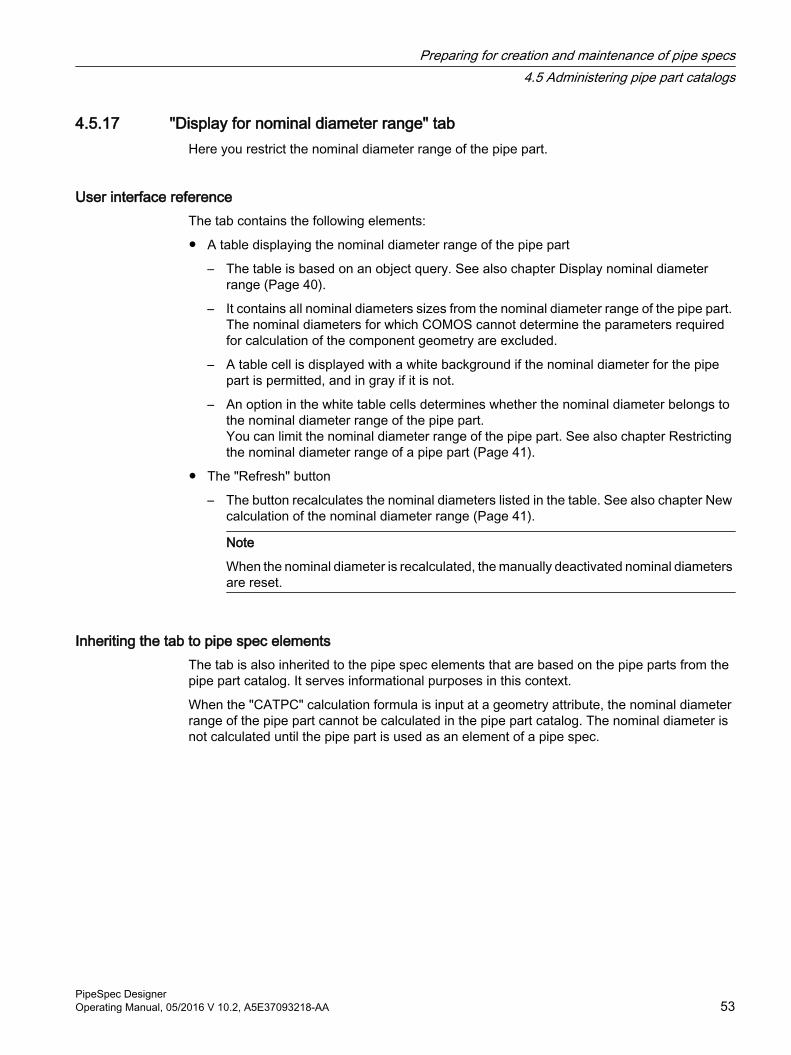
4.5.17 "Display for nominal diameter range" tabHere you restrict the nominal diameter range of the pipe part.
User interface referenceThe tab contains the following elements:
● A table displaying the nominal diameter range of the pipe part
– The table is based on an object query. See also chapter Display nominal diameter range (Page 40).
– It contains all nominal diameters sizes from the nominal diameter range of the pipe part. The nominal diameters for which COMOS cannot determine the parameters required for calculation of the component geometry are excluded.
– A table cell is displayed with a white background if the nominal diameter for the pipe part is permitted, and in gray if it is not.
– An option in the white table cells determines whether the nominal diameter belongs to the nominal diameter range of the pipe part.You can limit the nominal diameter range of the pipe part. See also chapter Restricting the nominal diameter range of a pipe part (Page 41).
● The "Refresh" button
– The button recalculates the nominal diameters listed in the table. See also chapter New calculation of the nominal diameter range (Page 41).
Note
When the nominal diameter is recalculated, the manually deactivated nominal diameters are reset.
Inheriting the tab to pipe spec elementsThe tab is also inherited to the pipe spec elements that are based on the pipe parts from the pipe part catalog. It serves informational purposes in this context.
When the "CATPC" calculation formula is input at a geometry attribute, the nominal diameter range of the pipe part cannot be calculated in the pipe part catalog. The nominal diameter is not calculated until the pipe part is used as an element of a pipe spec.
Preparing for creation and maintenance of pipe specs4.5 Administering pipe part catalogs
PipeSpec DesignerOperating Manual, 05/2016 V 10.2, A5E37093218-AA 53
4.6 Creating a pipe part type
4.6.1 Creating a pipe part type
DefinitionA pipe part type is an object that is used to sort pipe parts into categories by their function code from within the pipe specs. The name of pipe part types corresponds to a function code. The name contains any number of placeholders, which are marked with "X".
The pipe part type "21XXX elbow" covers, for example, all pipe parts of a pipe spec whose function code consists of the number "21" and any other three digits.
See also chapter Standard table for function codes (Page 54).
Structuring pipe part typesStructure the pipe part types so that you can access all pipes or elbows of a pipe spec, for example, using the pipe part type. Each PipeSpec element should only be sorted into one category.
Exception: The "XXXXX" pipe part type is also permitted.
Creating a new pipe part type1. Select the root node for the pipe part types in the base data.
The project properties in the "PipeSpec Designer" category show where you find the base objects of the pipe part types in the database.
2. Select "New > New base object" in the context menu.
3. Open the properties of the new object and click on the "System" tab.
4. "Name" field: Enter the initial digits of the function code as the name. For the characters which are variable, set an "X". Example: 21XXX. The name has to contain five characters.
5. "Description" field: Enter the function type.
4.6.2 Standard table for function codes
Purpose of function codesFunction codes are codes that are used to categorize pipe parts when working with pipe specs.
The function codes are grouped in a standard table. The standard table is stored at the "Y00T00011.Y00A00002 Function code" attribute at pipe parts.
Standard table for function codes: "Standard tables > Y10 > M23 > A10 > Y10M23N00001 Function code"
Preparing for creation and maintenance of pipe specs4.6 Creating a pipe part type
PipeSpec Designer54 Operating Manual, 05/2016 V 10.2, A5E37093218-AA
Permitted valuesSome of the function codes are fixed programmed in COMOS.
Furthermore, certain function code ranges are reserved for specific component types.
Example:
● The function code range between 10000 and 10010 is reserved for types of pipe specs.
● The function code range between 11100 and 11199 is reserved for general pipes.
See also chapter Linking the P&ID function code to the function codes (Page 131).
4.7 Managing standards
4.7.1 Creating a new system of standards
4.7.1.1 Overview: Creating a new system of standardsThe standard catalog contains geometry standards based on the DIN/EN and ANSI/ASME systems of standards. If your engineering is to be based on a different system of standards, you create a new system of standards.
To create a new system of standards, expand the following catalogs:
● "Standard tables > Y10 > M20 > Y30 > A10 System standard depending tables"
● "@30 > M23 > A10 > Y30 > A10 Standard geometry tables"
● "@50 > A10 > A10 > A10 Pipe part catalog"
Procedure1. Create a node with the standard table that describes the new system of standards. See
chapter Creating standard tables for a system of standards (Page 56).
2. Open the following standard table:"Y10 > M23 > A10 > Y10M23N00023 Systems of standards".
3. Create an entry for the new system of standards.
– Enter a description.
– Enter the name of the new node, which contains the standard tables of the new system of standards, into the "Value 1" column. See also chapter Creating standard tables for a system of standards (Page 56).
4. Create a node under the object "standard geometry tables", which describes the structure objects and tables for the new system of standards.See chapter Extending a system of standards in the "standard geometry tables" (Page 57).
5. Optional: Create new tabs or attributes for the standard geometry tables.See chapter Adding attributes or tabs for the "standard geometry tables" (Page 57).
Preparing for creation and maintenance of pipe specs4.7 Managing standards
PipeSpec DesignerOperating Manual, 05/2016 V 10.2, A5E37093218-AA 55

6. Create a node under the object "Pipe parts catalog", which contains the pipe parts for the new system of standards. See chapter Extending a pipe part catalog (Page 43).
7. Edit the contents of the new system of standards.
8. Use the new standard in the pipe part catalog. See chapter Extending a system of standards in the pipe part catalog (Page 58).
See alsoConfiguring geometry standards for bolts (Page 60)
Configuring geometry standards for nuts and washers (Page 61)
4.7.1.2 Creating standard tables for a system of standards
Procedure1. Navigate to the node that contains the standard tables that are dependent on the system
of standards:"Standard tables > Y10 > M20 > Y30 > A10 System standard depending tables"
2. Select an underlying node that collects the standard tables of a system of standards.Example: "1 DIN/EN"
3. Select the "Copy structure" command from the context menu.The structure is created parallel to the selected object. It contains the suffix "_1".
NoteObject name as identification
The object name must match the entry in the "Value 1" column of the following standard table:
"Standard tables > Y10 > M23 > A10 > Y10M23N00023 System of standards"
4. Edit the standard tables or create new standard tables.You can find additional information on this topic in the "Administration" manual, keyword "Creating or editing standard tables".If you create a new standard table, set this up in all systems of standards. Within the systems of standards, the standard table must be in the the same position in the structure and the name must be identical.
NoteDo not delete
Do not delete any standard tables. Do not delete any existing entries in standard tables.
Preparing for creation and maintenance of pipe specs4.7 Managing standards
PipeSpec Designer56 Operating Manual, 05/2016 V 10.2, A5E37093218-AA
4.7.1.3 Extending a system of standards in the "standard geometry tables"
Procedure1. Navigate to the node that contains the standard geometry tables:
"@30 > M23 > A10 > Y30 > A10 Standard geometry tables"
2. Select an underlying node that collects the structure objects and geometry tables of a system of standards.Example: "1 acc. to DIN/EN"
3. Select the "Copy structure" command from the context menu.The structure is copied and created parallel to the selected object. It contains the suffix "_1".
4. Enter the name of the new system of standards in the description.
5. Enter a new name for the object.
NoteName of the geometry tables
The names of the geometry tables must correspond to the entries of the new standard table in
the "Value 1" column.
6. Edit the properties of the structure objects and the standard geometry tables.Optional: Select a new value on the "Attributes > Dimensions" tab in the "Parameter name" list.
– "Parameter name" of the object equal to "- - -":Name of the structure object can be freely selected.
– "Parameter name" not equal to "- - -":Only values which can have the attribute addressed with "Parameter name" are permitted as name of the structure object. See also chapter Extending the "Standard parameterization table" (Page 25).
7. Open the "Attributes > Dimensions" tab.
8. Change the dimensions that were taken from the template from the nominal-diameter-dependent table.
See alsoAdding attributes or tabs for the "standard geometry tables" (Page 57)
4.7.1.4 Adding attributes or tabs for the "standard geometry tables"If possible, add tabs or attributes to the attribute catalog of the "standard geometry tables" standard catalog.
Preparing for creation and maintenance of pipe specs4.7 Managing standards
PipeSpec DesignerOperating Manual, 05/2016 V 10.2, A5E37093218-AA 57
Procedure1. Select the "Base objects" tab in the Navigator.
2. To edit or add attributes, open the following node:"@40 > A20 > Y00 > A10 > A30 > Y00T00055 > A03 Dimensions (standard geometry tables)"Create the required attributes on the "Dimensions" tab.You can find additional information on this topic in the "Administration" manual, keyword "Creating tabs and attributes".The new attributes are automatically applied to the "standard geometry tables" in the "@30" node.
3. To add new tabs, proceed as usual.You can find additional information on this topic in the "Administration" manual, keyword "Creating tabs and attributes".
4. If you have created a new tab, use it in the template folder at the corresponding objects under the following node:"@10 > A20 > A20 > A20 > A10 Geometry tables"Refer to the "Catalog tab" field on the tab that you have recently created.The new tab is automatically applied to the "standard geometry tables" in the "@30" node.
See alsoOverview: Creating a new system of standards (Page 55)
4.7.1.5 Extending a system of standards in the pipe part catalog
Procedure1. Navigate to a node in the pipe part catalog which contains pipe parts that are dependent
on the system of standards:Example: "@50 > A10 > A10 > A10 > 1 DIN/EN metric"
2. Select the "Copy structure" command from the context menu.The structure is created parallel to the selected object. It contains the suffix "_1".
3. Enter the name of the new system of standards in the description.
4. Select a new system of standards on the pipe parts on the "Attributes > Part description" tab in the "System of standards" attribute.
5. In order to apply the value to all "System of standards" attributes of the object, click on the "Update attributes" button.The standard tables at the attributes of the pipe part objects are switched by the shift in the system of standards.Hint: Change the bulk processing in order to change the system of standards at all objects. You can find additional information on this topic in the "Administration" manual, keyword "Bulk processing".
6. Optional: Change the remaining properties of the copied pipe part objects.See also chapters Using the "CatStd(...)" function (Page 32) and Administering pipe part catalogs (Page 27).
Preparing for creation and maintenance of pipe specs4.7 Managing standards
PipeSpec Designer58 Operating Manual, 05/2016 V 10.2, A5E37093218-AA
4.7.2 Extending a standard in a system of standards
4.7.2.1 Creating geometry standardsIf a geometry standard is missing from a system of standards, you can create one.
Example: You would like to create a new standard collection under the following node:
"@30 > M23 > A10 > Y30 > A10 > 1 > A60 > 1 > A10 Geometry contact face"
● Extend the standard table for geometry contact areas.
● Extend the standard geometry tables.
ProcedureThe description is based on the example for the creation of a new geometry contact area.
1. Navigate to the standard table that describes the geometry contact areas."Standard tables > Y10 > M20 > Y30 > A10 > 1 > A60 Contact faces"
2. Enter the new standard in the standard table.
NoteDelete can cause errors● Do not delete any standard tables. ● Do not delete any existing entries in standard tables.
3. Navigate to the layer in the standard geometry tables on which the standard collections of the geometry contact areas are managed."@30 > M23 > A10 > Y30 > A10 > 1 > A60 > 1 > A10 Geometry contact face"
4. Copy an existing standard collection via the context menu using the "Copy structure" command.COMOS creates a copy of the standard node, its structure objects and tables.
5. Open the properties of the copy and give the new standard a suitable name and description.
6. Edit the geometry tables:
– Change the name and the description.
NoteNames of the geometry tables in the "Value 1" column
The names of the standard geometry tables must correspond to the entries in the "Value 1" column of the abovementioned standard table.
– Create new structure objects or delete nodes if necessary.Example: Delete nodes for invalid pressure stages on the nominal pressure stage layer or amend the layer by adding more pressure stages.
7. Open the "Dimensions" tab of the standard geometry tables.
8. Edit the properties according to the templates of the missing standard.
Preparing for creation and maintenance of pipe specs4.7 Managing standards
PipeSpec DesignerOperating Manual, 05/2016 V 10.2, A5E37093218-AA 59
See alsoExtending a system of standards in the pipe part catalog (Page 58)
4.7.2.2 Adding values to the geometry tablesYou can supplement the dimensions entered in the standard geometry tables.
The nominal diameters are managed in the standard geometry tables and can vary according to the component.
Procedure1. Navigate to a geometry table.
Example: "@30 > M23 > A10 > Y30 > A10 > 1 > A40 > A10 > A10 Face-to-face dimensions of pipe caps according to DIN 2617"
2. Open the "Attributes > Dimensions" tab in the properties.
3. To add a new nominal diameter, extend the standard table for nominal diameters in the corresponding system of standards."Standard tables > Y10 > M20 > Y30 > A10 > 1 > A50 Nominal Sizes"You can find additional information on this topic in the "Platform Administration" manual, keyword "Creating the standard table values in the standard tables".
4. To add a new nominal diameter into the geometry table, create a new row in the table.
5. Enter the dimensions for the new nominal diameter.
4.7.2.3 Configuring geometry standards for bolts
RequirementYou have created a new geometry standard for bolt parts.
Procedure1. Open the node of the newly created system of standards structure object.
You see the structure objects for the screw types (e.g. screws, screw bolts).
2. For each structure object which defines a screw type: Open the properties and enter a description, e.g. "<bolt type> acc. to <description of the geometry standard>".
3. For each structure object which defines a screw type: Open the node.You see the objects defining the geometry standards of the screws.
Preparing for creation and maintenance of pipe specs4.7 Managing standards
PipeSpec Designer60 Operating Manual, 05/2016 V 10.2, A5E37093218-AA
4. For each object which defines a geometry standard:
– Open the properties.
– Modify the name and description.
– Enter the bolt step lengths on the "Attributes > Dimensions" tab.
– Save your entries.
5. Assign the geometry standard to an appropriate screw part. Amend the pipe part catalog first if necessary. See also chapter Extending a system of standards in the pipe part catalog (Page 58). The attributes catalog does not have to be amended.
4.7.2.4 Configuring geometry standards for nuts and washers
RequirementYou have created a new geometry standard for bolt parts.
Procedure1. Open the node of the newly created system of standards structure object.
– For a geometry standard for nuts: You see the structure objects for the nut types.
– For a geometry standard for washers: You see the objects defining the geometry standards (geometry tables).
2. For a geometry standard for nuts:
– For each structure object which defines a nut type: Open the properties and enter a description, e.g. "<nut type> acc. to <description of the geometry standard>".
– For each structure object which defines a nut type: Open the node.You see the objects defining the standard geometry tables for nuts (basic tables).
3. For each standard geometry table: Open the properties.For nuts: Enter the following data for all dimensions on the "Attributes > Dimensions" tab:
– "L1" column: The nut height
– "L2" column: The overlap
– "P" column: The pitch
For washers: Enter the height of the washer in the "L1" column on the "Attributes > Dimensions" tab.
4. Save your entries.
5. Assign the geometry standard to an appropriate screw part. Amend the pipe part catalog first, if necessary. See also chapter Extending a system of standards in the pipe part catalog (Page 58).
Preparing for creation and maintenance of pipe specs4.7 Managing standards
PipeSpec DesignerOperating Manual, 05/2016 V 10.2, A5E37093218-AA 61
See alsoAdding values to the geometry tables (Page 60)
Preparing for creation and maintenance of pipe specs4.7 Managing standards
PipeSpec Designer62 Operating Manual, 05/2016 V 10.2, A5E37093218-AA
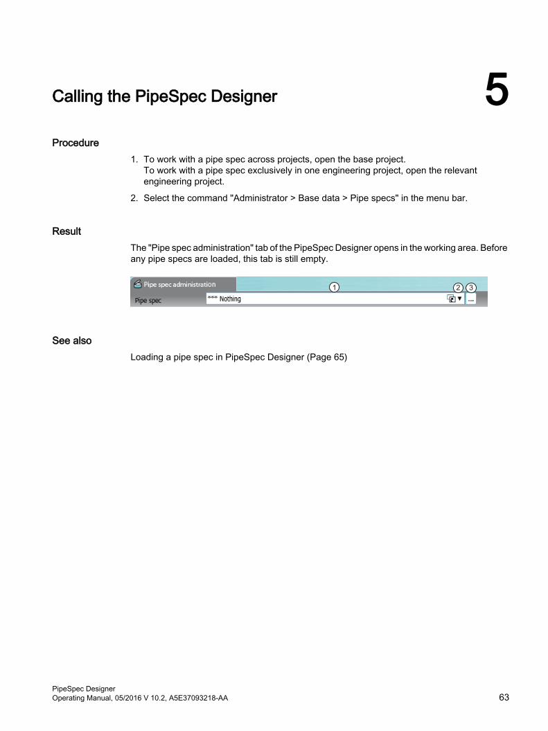
Calling the PipeSpec Designer 5Procedure
1. To work with a pipe spec across projects, open the base project.To work with a pipe spec exclusively in one engineering project, open the relevant engineering project.
2. Select the command "Administrator > Base data > Pipe specs" in the menu bar.
ResultThe "Pipe spec administration" tab of the PipeSpec Designer opens in the working area. Before any pipe specs are loaded, this tab is still empty.
See alsoLoading a pipe spec in PipeSpec Designer (Page 65)
PipeSpec DesignerOperating Manual, 05/2016 V 10.2, A5E37093218-AA 63

Calling the PipeSpec Designer
PipeSpec Designer64 Operating Manual, 05/2016 V 10.2, A5E37093218-AA
Loading a pipe spec in PipeSpec Designer 6Requirement
● A pipe spec was created.
● The "Pipe spec administration" tab of the PipeSpec Designer is open. See also chapter Calling the PipeSpec Designer (Page 63).
Procedure1. On the "Pipe spec administration" tab, click the "..." button next to the "Pipe spec" field.
The "Load pipe spec" window will open.Depending on whether you are in the base data view or in the engineering view, the "Load pipe spec" window displays one or two tabs.
2. If you are working in an engineering project, select a tab in the "Load pipe spec" window:
– To load a pipe spec that was created in an engineering project, select the "Engineering project" tab.
– To load a system class, select the "Base project" tab.
Note
Pipe specs that are created in the base project are read-only in the engineering project.
If you are working in the base project, only the "Current project" tab is available to you. Here you see the system classes.
3. To load a pipe spec, select the desired pipe spec in the structure tree.
4. Confirm your entries.
PipeSpec DesignerOperating Manual, 05/2016 V 10.2, A5E37093218-AA 65
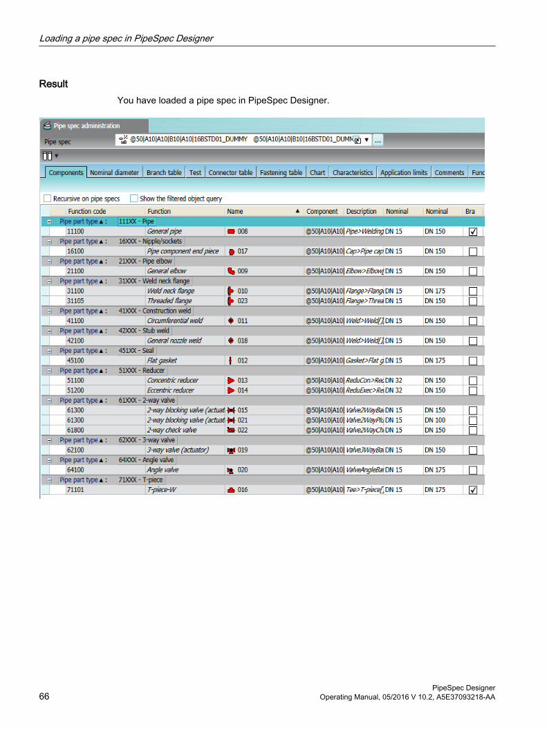
ResultYou have loaded a pipe spec in PipeSpec Designer.
Loading a pipe spec in PipeSpec Designer
PipeSpec Designer66 Operating Manual, 05/2016 V 10.2, A5E37093218-AA
Generating pipe specs 77.1 Options for creating a new pipe spec
You have the following options for creating a new pipe spec:
● When you use a template, you make a copy of an existing pipe spec and modify it according to your needs. See also chapter Creating a new pipe spec from a template (Page 68).
● When the new pipe spec differs significantly from the existing pipe spec, you create a completely new pipe spec without a template. See also chapter Creating a new pipe spec without a template (Page 67).
7.2 Creating a new pipe spec without a template
RequirementThe "Pipe spec administration" tab of the PipeSpec Designer is open. See also chapter Calling the PipeSpec Designer (Page 63).
Procedure1. To open the "Load pipe spec" window, click the "...". button next to the "Pipe spec" field on
the "Pipe spec administration" tab.See also chapter The "Load pipe spec" window (Page 69).
2. In the structure tree, select the node under which you want to insert the new pipe spec.
3. Select one of the following commands from the "New" context menu:
– "COMOS pipe spec":Creates the new pipe spec. Opening the pipe spec in the PipeSpec Designer loads all tabs relevant for pipe specs.
– "PDMS pipe spec":Creates the new PDMS pipe spec. Opening the pipe spec in the PipeSpec Designer loads all tabs relevant for PDMS pipe specs.The new pipe spec is created in the structure tree and the base data.
4. Edit the automatically generated name and the description.
5. Click the "OK" button.
ResultThe "Load pipe spec" window closes and the new pipe spec is loaded to the PipeSpec Designer.
PipeSpec DesignerOperating Manual, 05/2016 V 10.2, A5E37093218-AA 67
7.3 Creating a new pipe spec from a template
Requirement● A pipe spec has been created.
● The "Pipe spec administration" tab of the PipeSpec Designer is open. See also chapter Calling the PipeSpec Designer (Page 63).
Procedure1. To open the "Load pipe spec" window, click the "...". button next to the "Pipe spec" field on
the "Pipe spec administration" tab.See also chapter The "Load pipe spec" window (Page 69).
2. In the structure tree, select the pipe spec to be used as a template.
3. Select the "Copy" command in the context menu.
4. If you are working in an engineering project and the selected template is a system class, go to the "Engineering project" tab.
5. Select the root node in the structure tree followed by the "Paste" command from the context menu.
– A copy of the pipe spec is created in the structure tree and the base data.
– The name and description are generated for the new pipe spec.
6. Edit the automatically generated name and the description in the upper area of the "Load pipe spec" window to meet your needs.
7. Click the "OK" button.
ResultThe "Load pipe spec" window closes and the new pipe spec is loaded to the PipeSpec Designer.
See alsoCreating a new pipe spec without a template (Page 67)
Generating pipe specs7.3 Creating a new pipe spec from a template
PipeSpec Designer68 Operating Manual, 05/2016 V 10.2, A5E37093218-AA
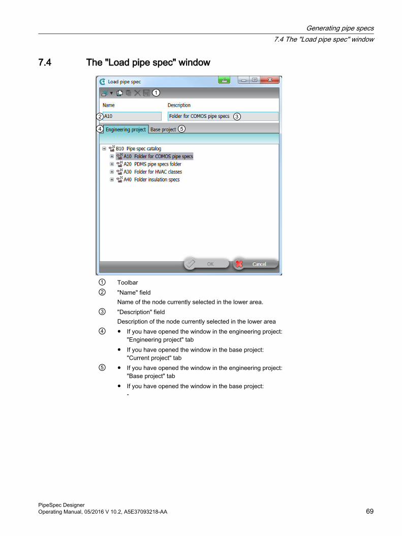
7.4 The "Load pipe spec" window
① Toolbar② "Name" field
Name of the node currently selected in the lower area.③ "Description" field
Description of the node currently selected in the lower area④ ● If you have opened the window in the engineering project:
"Engineering project" tab● If you have opened the window in the base project:
"Current project" tab⑤ ● If you have opened the window in the engineering project:
"Base project" tab● If you have opened the window in the base project:
-
Generating pipe specs7.4 The "Load pipe spec" window
PipeSpec DesignerOperating Manual, 05/2016 V 10.2, A5E37093218-AA 69
You are in an engineering project.When you open the window in an engineering project, you will see the following tabs:
● "Base project" tab:The tab displays the system classes.System classes are created in the base project. They are available on a project-wide basis. They can be used as templates for project-specific pipe specs.In engineering projects, system classes are write-protected.
● "Engineering project" tabThis is where you define the pipe specs created locally in an engineering project. They are marked as local base objects in the structure tree.If the same node is entered in the engineering project as in the base project, you also see the system classes.
You are in a base project.When you open the window in a Base project, you will see the "Current project" tab:
You define the system classes in this tab.
System classes are created in the base project. They are available on a project-wide basis. They can be used as templates for project-specific pipe specs.
Generating pipe specs7.4 The "Load pipe spec" window
PipeSpec Designer70 Operating Manual, 05/2016 V 10.2, A5E37093218-AA
Managing pipe specs 88.1 Deleting a pipe spec
Note
Do not delete any pipe spec that is used in the engineering data.
RequirementThe "Pipe spec administration" tab of the PipeSpec Designer is open. See also chapter Calling the PipeSpec Designer (Page 63).
Procedure1. To open the "Load pipe spec" window, click the "...". button next to the "Pipe spec" field on
the "Pipe spec administration" tab.
2. Select the required pipe spec in the lower area of the window.
3. Select "Delete" from the context menu.The "Delete pipe spec" window will open.
4. Confirm with "OK".
5. Close the "Load pipe spec" window.
8.2 Creating folders for structuring the pipe specs
RequirementThe "Pipe spec administration" tab of the PipeSpec Designer is open. See also chapter Calling the PipeSpec Designer (Page 63).
Procedure1. To open the "Load pipe spec" window, click the "...". button next to the "Pipe spec" field on
the "Pipe spec administration" tab.
2. In the structure tree, select the node under which you wish to paste a folder.
3. Select the "New > Folder" command in the context menu.
PipeSpec DesignerOperating Manual, 05/2016 V 10.2, A5E37093218-AA 71

Managing pipe specs8.2 Creating folders for structuring the pipe specs
PipeSpec Designer72 Operating Manual, 05/2016 V 10.2, A5E37093218-AA
Configuring pipe specs 99.1 Overview for configuring pipe specs
Requirement● The general requirements for working with the PipeSpec Designer have been met.
See also chapter Preparing for creation and maintenance of pipe specs (Page 15).
● You have loaded a pipe spec in PipeSpec Designer.See also chapter Loading a pipe spec in PipeSpec Designer (Page 65).
WorkflowConfigure the tabs in the following order:
1. "Pipe spec limits". See chapter Configuring the "PipeSpec limits" tab (Page 74).
2. "Characteristics". See chapter Configuring the "Characteristics" tab (Page 78).
3. "Pipe parts". See chapter Configuring the "Components" tab (Page 81).
4. "Nominal diameters". See chapter "Nominal diameters" tab: (Page 84).
5. "Branch table". See chapter "Branch table" tab (Page 89).
6. "Connector table". See chapter "Connector table" tab (Page 94).
7. "Fastening table": See chapter "Fastening table" tab (Page 99).
8. If required: "Comments". See section "Comments" tab (Page 103)
Displaying a tab in an additional window"Pipe parts" button:
Use this button to display a tab of the PipeSpec Designer in an additional window. The additional window does not have any extra functions, but serves to simplify the configuration of the tabs.
Previously configured tabs● "Diagram":
The PipeSpec Designer evaluates data configured at the pipe components and displays it on the tab. A configuration is not required.
● "Function":Saves data for internal purposes.
PipeSpec DesignerOperating Manual, 05/2016 V 10.2, A5E37093218-AA 73
Additional tabsAs administrator you can define additional tabs for the base object of a pipe spec, which are then also displayed and configured in the PipeSpec Designer.
9.2 Configuring the "PipeSpec limits" tabHere you specify the following:
● System of standards
● Application limits
● Dimensions for external diameter and wall thickness
9.2.1 Choosing a system of standards
Requirement● You have loaded a pipe spec in PipeSpec Designer. See also chapter Loading a pipe spec
in PipeSpec Designer (Page 65).
● The "Pipe spec limits" tab is open.
Procedure1. Select a system of standards in the "System of standards" list.
2. Click the "Update attributes" button.
ResultThe standard tables at pipe spec attributes depending on a system of standards are changed depending on your selection.
See alsoOverview for configuring pipe specs (Page 73)
9.2.2 Defining the nominal diameter range
Requirement● You have loaded a pipe spec in PipeSpec Designer. See also chapter Loading a pipe spec
in PipeSpec Designer (Page 65).
● The "Pipe spec limits" tab is open.
Configuring pipe specs9.2 Configuring the "PipeSpec limits" tab
PipeSpec Designer74 Operating Manual, 05/2016 V 10.2, A5E37093218-AA
Procedure1. Adjust the high and low limit in the "Nominal diameter range" control group in the fields
"From nominal diameter" and "To nominal diameter".
2. To filter individual values from the nominal diameter range, click the following button:
You can see a list of all nominal diameters that lie between the upper and lower limits defined in step 1.
3. Optional:
– To exclude a nominal diameter from the nominal diameter range of the pipe spec, deactivate the option next to the nominal diameter.
– To add a nominal diameter to the nominal diameter range of the pipe spec, activate the option next to the nominal diameter.
1. Click the "Update NDs" buttonThe nominal diameter range you defined is forwarded to:
– The rest of the tabs in the PipeSpec Designer
– The pipe spec elements
2. The pipe spec elements are available in the nominal diameter range specified by the pipe spec
3. Save your entries.
See alsoDefining nominal-diameter-dependent parameters (Page 79)
9.2.3 Defining the application limits of the specThe table for the pressure/temperature rating in the "Class use limit" control group is used for pipe spec documentation. It is informational in character and independent of the pressure/temperature rating of the pipe parts.
The values entered here are evaluated on the "Chart" tab and displayed in a diagram.
Requirement● Observing the workflow for configuration of pipe specs. See also chapter Overview for
configuring pipe specs (Page 73).
● You have loaded a pipe spec in PipeSpec Designer. See also chapter Loading a pipe spec in PipeSpec Designer (Page 65).
● The "Pipe spec limits" tab is open.
Configuring pipe specs9.2 Configuring the "PipeSpec limits" tab
PipeSpec DesignerOperating Manual, 05/2016 V 10.2, A5E37093218-AA 75
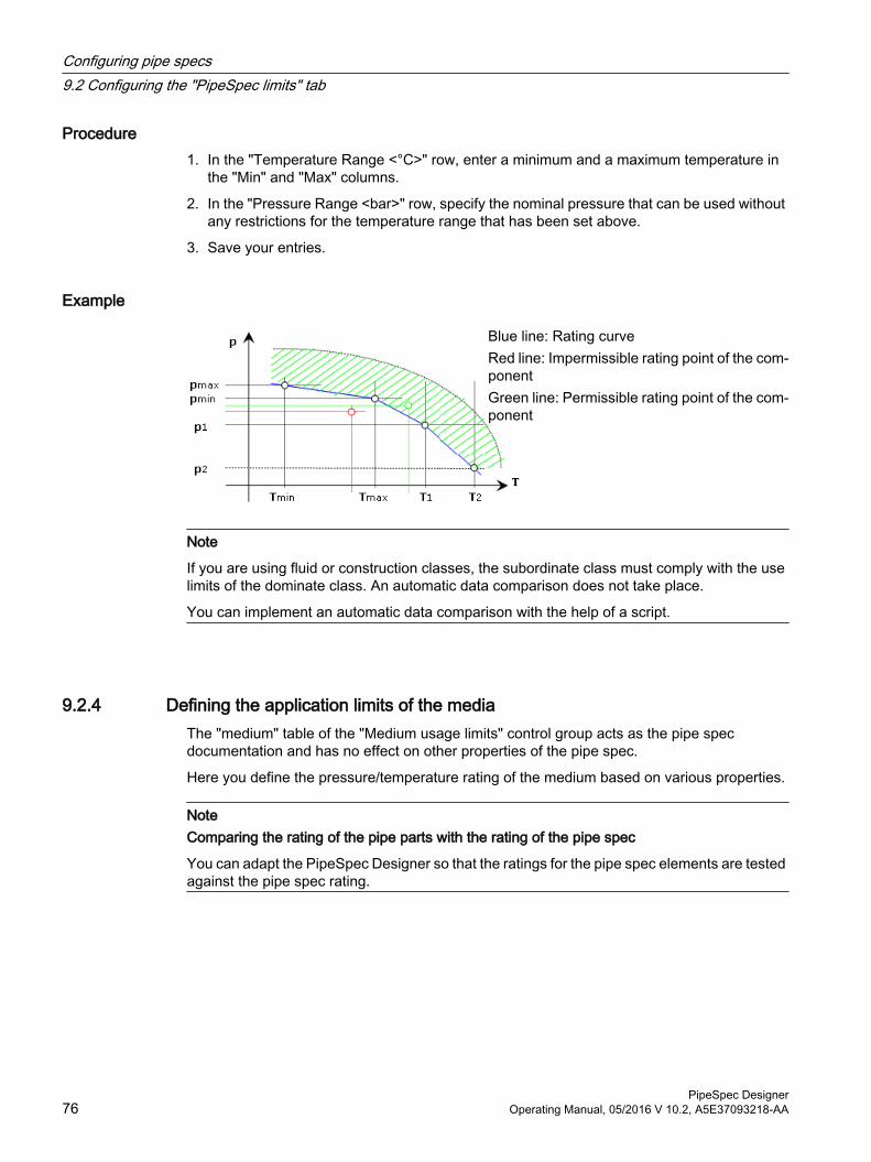
Procedure1. In the "Temperature Range <°C>" row, enter a minimum and a maximum temperature in
the "Min" and "Max" columns.
2. In the "Pressure Range <bar>" row, specify the nominal pressure that can be used without any restrictions for the temperature range that has been set above.
3. Save your entries.
Example
Blue line: Rating curveRed line: Impermissible rating point of the com‐ponentGreen line: Permissible rating point of the com‐ponent
Note
If you are using fluid or construction classes, the subordinate class must comply with the use limits of the dominate class. An automatic data comparison does not take place.
You can implement an automatic data comparison with the help of a script.
9.2.4 Defining the application limits of the mediaThe "medium" table of the "Medium usage limits" control group acts as the pipe spec documentation and has no effect on other properties of the pipe spec.
Here you define the pressure/temperature rating of the medium based on various properties.
NoteComparing the rating of the pipe parts with the rating of the pipe spec
You can adapt the PipeSpec Designer so that the ratings for the pipe spec elements are tested against the pipe spec rating.
Configuring pipe specs9.2 Configuring the "PipeSpec limits" tab
PipeSpec Designer76 Operating Manual, 05/2016 V 10.2, A5E37093218-AA
Requirement● Observing the workflow for configuration of pipe specs. See also chapter Overview for
configuring pipe specs (Page 73).
● You have loaded a pipe spec in PipeSpec Designer. See also chapter Loading a pipe spec in PipeSpec Designer (Page 65).
● The "Pipe spec limits" tab is open.
Procedure1. For each row, define the pressure/temperature rating for a property, for example, the "liquid"
and "gas" properties.
2. Enter the temperature and the pressure in the "Temp<Counter>" and "Pres<Counter>" columns.
3. Save your entries.
9.2.5 Defining the outer diameter and wall thicknessIn the "Characteristics series" of the "Characteristics" tab, the values in the "Outer diameter" and "Wall thickness" columns are either entered by the user or taken from the "standard geometry tables" standard catalog.
If the characteristics are to be taken from the standard catalog, specify which basic table is to be used on the "PipeSpec limits" tab.
Requirement● Observing the workflow for configuration of pipe specs. See also chapter Overview for
configuring pipe specs (Page 73).
● You have loaded a pipe spec in PipeSpec Designer. See also chapter Loading a pipe spec in PipeSpec Designer (Page 65).
● The "Pipe spec limits" tab is open.
● In the "Class characteristics nominal-diameter-dependent" attribute on the "Characteristics" tab, the "OnShow" script block is implemented as in the database. See also chapter Defining nominal-diameter-dependent parameters (Page 79).
Procedure1. Click on the "..." button on the right of the "Catalog name for outer diameters" or "Catalog
name for wall thicknesses" field.
2. Select a geometry table in the catalog.See also chapter Structure of the standard catalog for geometry standards (Page 23).
3. Click "OK" to confirm.A reference to the geometry table is entered in the "Catalog name <...>" field.
Configuring pipe specs9.2 Configuring the "PipeSpec limits" tab
PipeSpec DesignerOperating Manual, 05/2016 V 10.2, A5E37093218-AA 77
4. In the "Column in catalog" list, select the column of the geometry table from which the dimension value is to be read.
5. Save your entries.
ResultThe values are read from the geometry table and written to the nominal-diameter-dependent characteristics table on the "Characteristics" tab.
9.3 Configuring the "Characteristics" tabHere you define additional characteristics of the pipe spec. For example, define which nominal-diameter-dependent characteristics the pipe spec gives.
9.3.1 Defining the fluid characteristics of the spec
Requirement● Observing the workflow for configuration of pipe specs. See also chapter Overview for
configuring pipe specs (Page 73).
● You have opened the "Characteristics" tab.
● You are working in the "Class fluid parameters" control group.
Procedure1. Select the "Fluid type".
2. Select the "Fluid key".
3. Select the "Flow medium" of the pipe spec.
4. Save your entries.
9.3.2 Defining the fluid group according to the DGRL
Requirement● Observing the workflow for configuration of pipe specs. See also chapter Overview for
configuring pipe specs (Page 73).
● You have opened the "Characteristics" tab.
● You are working in the "Fluid group acc. to DGRL" control group.DGRL = pressure equipment directiveThis control group is used for pipe spec documentation.
Configuring pipe specs9.3 Configuring the "Characteristics" tab
PipeSpec Designer78 Operating Manual, 05/2016 V 10.2, A5E37093218-AA
Procedure1. Select a fluid group.
2. Save your entries.
9.3.3 Defining other characteristics of the pipe spec
Requirement● Observing the workflow for configuration of pipe specs. See also chapter Overview for
configuring pipe specs (Page 73).
● You have opened the "Characteristics" tab.
● You are working in the "Class characteristics" and "Connector descriptions" control groups.
Procedure1. Select a material in the "Pipe material" field.
The corresponding material number is automatically transferred to the "Material number" attribute.
2. Enter the material density in the "Material density" field. The material density can be used for further calculations.
3. Select the primary contact face in the "Contact face" field.
4. Select the strength grade of screws in the "Strength grade screws" field and the strength grade of nuts in the "Strength grade nuts" field.
5. Save your entries.
9.3.4 Defining nominal-diameter-dependent parametersIn the "Classes characteristics nominal-diameter-dependent" control group define the nominal-diameter-dependent characteristics in a table.
The table is generally used for pipe spec documentation.
The table is not for information only when the following conditions are met:
● You enter pipe-spec-dependent outer diameters and wall thicknesses.
● A pipe spec element is assigned its outer diameter and wall thickness via the calculation formula "CatPC".In this case, the pipe spec element uses the local dimensions of the pipe spec.
Configuring pipe specs9.3 Configuring the "Characteristics" tab
PipeSpec DesignerOperating Manual, 05/2016 V 10.2, A5E37093218-AA 79
Note● Do not configure the table until you have finished defining the nominal diameter range on
the "PipeSpec limits" tab.Reason: Clicking on the "Update NDs" button to forward new values can mix up the assignment between nominal diameters and other parameters.
● Do not configure the "Nominal diameter" row manually.Reason: The "Nominal diameter" row must always show the nominal diameter range defined on the "Application limits" tab. When you click the "Update NDs" button on the "Application limits" tab, the current nominal diameter range is written to the characteristic-dependent table. This can mix up the assignment between nominal diameters and the other characteristics.
Requirement● Observing the workflow for configuration of pipe specs. See also chapter Overview for
configuring pipe specs (Page 73).
● You have opened the "Characteristics" tab.
Procedure Enter the characteristics depending on the nominal diameter.
You have two options when configuring the "Outside diameter" and "Wall thickness" rows:
● Take the values from a geometry table. To do this, set a reference to a geometry table on the "Application limits" tab and specify a row.
● Enter the outer diameter for the pipe spec members manually.When you set a reference to a geometry table in the "Application limits" tab and specify a row, your entries are overwritten.
Table parameters
Column name Function"Nominal size" ● The nominal diameter range of the pipe spec
● Do not set manually"Outside diameter" Is evaluated if a pipe spec element gets the outer diameter via the "CatPC"
formula"Thickness" Same as "Outside diameter""Calculated wall thick‐ness"
Calculated by PROBAD in the case of a connection to PROBAD
"Minimum wall thickness" For COMOS Inspection"Corrosion allowance" For the nominal wall thickness"Minimum length" For constructing with COMOS Isometrics."Fitting length for x,y,z" For constructing with COMOS Isometrics."Bending radius" Self-explanatory.
Configuring pipe specs9.3 Configuring the "Characteristics" tab
PipeSpec Designer80 Operating Manual, 05/2016 V 10.2, A5E37093218-AA
See alsoUsing the "CatPC(...)" function (Page 39)
Defining the outer diameter and wall thickness (Page 77)
9.4 Configuring the "Components" tabOn the "Pipe parts" tab, you define the pipe spec elements of the pipe spec and the upper and lower limits of its nominal diameter range.
9.4.1 Pipe parts tableThe pipe part table provides an overview of and a means of managing the pipe spec and/or its elements.
Underlying queryThe pipe part table is based on a query which is located in the base data under the following node:
"@20 > A70 > Y10 > M23 > A20 > A10 Standard query for pipe specs"
The query defines which columns the pipe part table has.
Structure of the pipe part tableThe query preconfigured in the database defines the following columns:
● Column for the pipe part type:Groups the pipe spec elements into pipe part types by function code range.See also chapter Creating a pipe part type (Page 54).
● Columns "Function code" and "Function":Reads out the function code of the pipe part (numerical code and description).
● "Name":The pipe spec element is initially assigned the name of the pipe part from the pipe part catalog. The name can be overwritten. It must be unique.
● "Description":As with "Name".
● "Nominal diameter from" and "Nominal diameter to":Defines the nominal diameter range in which the pipe spec element is available in the pipe spec. Only nominal diameters from the current nominal diameter range of the pipe spec can be selected.
● "Branch parts":The option is activated by default for pipes and branch parts depending on the function code. These components are copied to the branch table.
Configuring pipe specs9.4 Configuring the "Components" tab
PipeSpec DesignerOperating Manual, 05/2016 V 10.2, A5E37093218-AA 81
"Recursive on pipe specs" optionThis option is relevant when you are working with nested pipe specs.
Option DescriptionDeactivated The following objects are visible in the pipe part table:
● Pipe spec elements you have assigned directly to the pipe spec loaded in the PipeSpec Designer
● The base object of the nested pipe spec.Activated ● An additional column appears in the pipe part table: The "Pipe class" column
which reads out the name of the pipe spec under which a pipe part is located in the base data.
● The table lists the same objects as when the option is deactivated, plus the members of the nested pipe spec.
"Show filtered object query" option
Option DescriptionDeactivated Conventional creation of pipe specs with drag&dropActivated If you have prepared filtered queries for a pipe spec, the results are displayed in
the upper area of the "Pipe parts" tab. You can drag the pipe spec elements to the lower area with drag&drop and add them to the pipe spec.
9.4.2 Assigning a new pipe part
Requirement● You have opened the "Base objects" tab in the Navigator.
● The pipe part catalog is open.
Procedure1. Select the desired pipe part in the Navigator.
2. Drag&drop it from the Navigator to the pipe part table.
3. Save.
Result● A pipe spec element is created under the pipe spec in the base data.
● The pipe spec element receives a base object reference to the pipe part from the pipe part catalog. This means it inherits from the catalog part.
● The pipe spec element has the "Application limits component" tab. It stores data for the nominal diameter range of the pipe spec element.
Configuring pipe specs9.4 Configuring the "Components" tab
PipeSpec Designer82 Operating Manual, 05/2016 V 10.2, A5E37093218-AA
NoteThe legend in the "Nominal diameters > <function code of the pipe part>" tab is not updated
When you add a new pipe part to a pipe spec, the legend of the pipe part in the "Preselected component" control group in the "Nominal diameters > <function code of the pipe part>" tab may have errors.
You can update the legend manually. See also chapter Updating the legend (Page 89).
Nested classesTo embed one pipe spec in another pipe spec, drag&drop the corresponding base object from the Navigator to the "Pipe parts" tab.
9.4.3 Navigating to the pipe partYou can navigate from the pipe part table to the base data.
Procedure1. Select the pipe spec element in the pipe part table.
2. Select the following command from the context menu:
– To navigate to the pipe spec element: "Navigate - pipe spec"
– To navigate to the pipe part in the pipe part catalog on which the pipe spec element is based: "Navigate - original"
9.4.4 Setting the upper and lower limits of the DN range of a pipe part
Procedure1. Select the pipe part in the pipe part table.
2. Define the lower limit in the "Nominal diameter from" column and the upper limit in the "Nominal diameter to" column.
3. Save your entries.
ResultThe pipe spec element is only available within the upper and lower limits defined here. The upper and lower limits are saved at the pipe spec element in the following attributes:
"Application limits component" tab, "Y00A02745 from nominal diameter" and "Y00A02744 up to nominal diameter" lists
Configuring pipe specs9.4 Configuring the "Components" tab
PipeSpec DesignerOperating Manual, 05/2016 V 10.2, A5E37093218-AA 83
Excluding nominal diameters from the nominal diameter rangeOn the "Nominal diameters" tab, you can exclude individual values from the range defined by "Nominal diameter from" and "Nominal diameter to".
See also"Nominal diameters" tab: (Page 84)
9.4.5 Adding a component to the branch table
Procedure1. Add a new component from the pipe part catalog to the pipe part table.
2. Select the option in the "Branch parts" column for this component.
3. Specify the permitted nominal diameter combinations.
ResultThe component is displayed in the "Branch parts" tab as preselected component.
Removing components from the branch table1. Select a branch pipe part in the pipe part table.
2. Deselect the option in the "Branch parts" column.
Resetting to standard selection of branch parts Select the command "Reset branch parts to standard" in the context menu of the table.
9.5 "Nominal diameters" tab:Shows the permitted nominal diameters of the pipe spec elements and their classification to pipe part types.
Here you define a preselected component for each nominal diameter for each pipe part type. You can also refine the nominal diameters in which a pipe part is available.
Configuring pipe specs9.5 "Nominal diameters" tab:
PipeSpec Designer84 Operating Manual, 05/2016 V 10.2, A5E37093218-AA
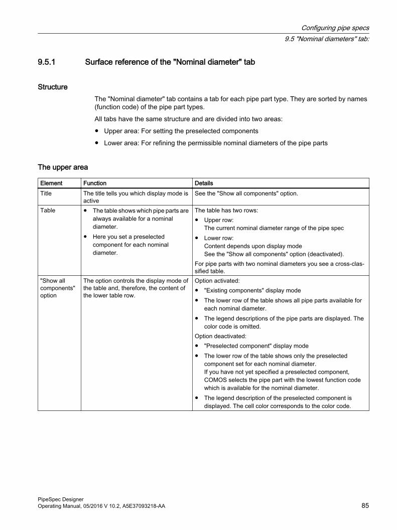
9.5.1 Surface reference of the "Nominal diameter" tab
StructureThe "Nominal diameter" tab contains a tab for each pipe part type. They are sorted by names (function code) of the pipe part types.
All tabs have the same structure and are divided into two areas:
● Upper area: For setting the preselected components
● Lower area: For refining the permissible nominal diameters of the pipe parts
The upper area
Element Function DetailsTitle The title tells you which display mode is
activeSee the "Show all components" option.
Table ● The table shows which pipe parts are always available for a nominal diameter.
● Here you set a preselected component for each nominal diameter.
The table has two rows:● Upper row:
The current nominal diameter range of the pipe spec● Lower row:
Content depends upon display modeSee the "Show all components" option (deactivated).
For pipe parts with two nominal diameters you see a cross-clas‐sified table.
"Show all components" option
The option controls the display mode of the table and, therefore, the content of the lower table row.
Option activated:● "Existing components" display mode● The lower row of the table shows all pipe parts available for
each nominal diameter.● The legend descriptions of the pipe parts are displayed. The
color code is omitted.Option deactivated:● "Preselected component" display mode● The lower row of the table shows only the preselected
component set for each nominal diameter.If you have not yet specified a preselected component, COMOS selects the pipe part with the lowest function code which is available for the nominal diameter.
● The legend description of the preselected component is displayed. The cell color corresponds to the color code.
Configuring pipe specs9.5 "Nominal diameters" tab:
PipeSpec DesignerOperating Manual, 05/2016 V 10.2, A5E37093218-AA 85
The lower areaThe table in the lower area meets the following functions:
● Provides an overview of the nominal diameters in which the pipe parts of the pipe part type are currently available.
● Provides an overview in which nominal diameters the pipe parts of the pipe part type are basically permitted.
● Changing the nominal diameter of the pipe parts.
The table is structured as follows:
● Left column: The legend descriptions of the pipe parts
● The remaining header columns: The current nominal diameter range of the pipe spec
Each row describes the nominal diameter range of a pipe part:
● White cell with check mark: The nominal diameter is currently available.
● White cell without check mark: The nominal diameter is always available.
● Gray cell: This nominal diameter cannot be within the nominal diameter range.
9.5.2 Preselected components
DefinitionPreselected components are those pipe parts returned by COMOS as standard values when the pipe part type is addressed.
Example: A user is working on an isometric drawing and places a pipe part using the symbol bar of the isometric drawing. The user selects a pipe part type and places the pipe part that is set as preselected component for the pipe part type and the selected nominal diameter.
9.5.3 Defining preselected components
Requirement● Observing the workflow for configuration of pipe specs. See also chapter Overview for
configuring pipe specs (Page 73).
● The "Nominal diameters" tab is open.
Configuring pipe specs9.5 "Nominal diameters" tab:
PipeSpec Designer86 Operating Manual, 05/2016 V 10.2, A5E37093218-AA
Procedure1. Click the tab of the required pipe part type.
The table listing the preselected components and the table for the nominal diameter ranges of the pipe parts are displayed.
2. Get an overview of which pipe parts can be set as preselected components for the nominal diameter. You have two options:
– Activate the "All components" option in the upper table.The legend descriptions of all available pipe parts are displayed in the cell for the required nominal diameter.
– Check the lower table to see which pipe parts are available for the nominal diameter.
3. If you only wish to define a preselected component for one nominal diameter, proceed as follows:
– To display a list with all pipe parts that are available as preselected component for the current nominal diameter, open the context menu in the required cell of the upper table.
– Select a pipe part.The pipe part is set as the preselected component.
– If the option "All components" is activated, deactivate the option to change into the display mode for preselected components.
4. To assign the same preselected component to several nominal diameters, proceed as follows:
– Press and hold down <Ctrl>, hold down the left mouse button, and drag out an area around the required nominal diameters in the upper table.
– To display a list of pipe parts which are available as preselected components for all selected nominal diameters, open the context menu.
– Select a pipe part from the list.The pipe part is set as the preselected component.
5. Save your entries.
Modifying the nominal diameters of a pipe partIn the lower table, you can modify the nominal diameters in which the pipe parts are available. This means that you can even set pipe parts as preselected components which are not available as preselected components initially due to their nominal diameter range.
Configuring pipe specs9.5 "Nominal diameters" tab:
PipeSpec DesignerOperating Manual, 05/2016 V 10.2, A5E37093218-AA 87
9.5.4 Limiting nominal diameter ranges
IntroductionThe nominal diameter range of a pipe spec element is formed by the average of the following quantities:
● The nominal diameter range of the pipe part from the pipe part catalog on which the pipe spec element is based.
● The nominal diameter range of the pipe spec.
In the PipeSpec Designer, you can further refine the nominal diameter range calculated in this way and define which nominal diameters are actually available.
Requirement● Observing the workflow for configuration of pipe specs. See also chapter Overview for
configuring pipe specs (Page 73).
● The "Nominal diameters" tab is open.
Procedure1. Select the tab of the pipe part type on the "Nominal diameters" tab.
You are working in the table for the nominal diameter ranges, in the row displaying the nominal diameter range of the pipe part.The pipe parts are displayed with their legend description.
2. Optional: Open the legend in the table for preselected components and identify which legend description and color stands for which pipe part. See also chapter Defining preselected components (Page 86).
3. To exclude a nominal diameter, double-click a white cell with check mark.The check mark disappears.
4. To add a nominal diameter once again, double-click a white cell.A check mark appears in the cell.
5. Save your entries.
Result● The nominal diameter range is saved as an XML string at the base object of the pipe spec
element: "Application limits component" tab, "Y00A04288 Nominal diameter range" attribute
● When the pipe spec is mapped, the pipe spec element is only available in the nominal diameter range defined in the XML string.
● If you have modified the upper or lower limit, the "Components" tab is updated accordingly.
Configuring pipe specs9.5 "Nominal diameters" tab:
PipeSpec Designer88 Operating Manual, 05/2016 V 10.2, A5E37093218-AA
Attribute for the nominal diameter range of a pipe spec elementYou will only find the attribute saving the nominal diameter range in the Navigator. The attribute is not placed on the "Application limits component" tab.
You can embed the XML string on a tab. See also chapter Display nominal diameter range (Page 40).
See alsoNominal diameter range of a pipe part (Page 40)
"Display for nominal diameter range" tab (Page 53)
9.5.5 Updating the legendWhen you add a new pipe part to a pipe spec, the legend of the pipe part in the "Preselected component" control group in the "Nominal diameters > <function code of the pipe part>" tab may have errors.
In this case, you can update the legend.
Procedure1. Select the "Nominal diameters > XXXXX" tab.
2. Save the pipe spec.
9.6 "Branch table" tabHere you specify which branch part is used if pipes are interconnected directly when constructing branches. A unique entry is set for each nominal diameter combination.
The table is not evaluated if you have already placed a branch part when constructing the branch. In this case, the component set as the preselected component for the pipe part type of the branch part is used.
9.6.1 Surface reference of the "Branch table" tab
StructureThe "Branch table" tab is divided into two areas.
Configuring pipe specs9.6 "Branch table" tab
PipeSpec DesignerOperating Manual, 05/2016 V 10.2, A5E37093218-AA 89
Upper half:
● The branch table and some options for controlling the display of the table and filtering its content.
● Purpose:If pipes are interconnected directly during construction, you specify here which branch part is used based on the nominal diameter.
Lower half:
List of branch parts with legend. Use the [...] button to open the nominal diameter range.
Content of the upper half● The branch table is a cross-classified table containing the nominal diameter combinations
of the pipe spec. It is generated from the nominal diameters that are entered in the nominal diameter dependent characteristics table of the pipe spec on the "Characteristics" tab.
– Horizontal axis: The nominal diameter of the branch
– Vertical axis: The main nominal diameter
● Each nominal diameter combination is stored with a list of all branch parts permitted for this nominal diameter combination.
● Either the names or the legend descriptions of the branch parts are listed in the branch table. The following options control the content and the display of the table:
Option Description"Show name" Shows the names of the branch parts."Show legend" Shows a legend defined by the user (number or letters)."Show all available components" Shows all branch parts that are permitted for a nominal
diameter combination."Only show preselected component" Shows only those branch parts that were set as preselec‐
ted components in the table.
● Each branch part is assigned a color. If you set a preselected component for a nominal diameter combination, the cell is displayed in the color assigned to the preselected component.
Content of the lower halfLegend:
Column Description"Pipe spec element" Name and Navigator text of the branch parts
Shows the branch parts for which the option in the "Branch part" column on the "Pipe parts" tab is selected.
"Legend" The currently assigned legend description"Color" The currently assigned color"Nominal diameter range" Button that opens the nominal diameter table
Configuring pipe specs9.6 "Branch table" tab
PipeSpec Designer90 Operating Manual, 05/2016 V 10.2, A5E37093218-AA
9.6.2 Defining branch partsIf you do not use the branch table or do not enter a branch for a certain nominal diameter combination, COMOS uses the component set as the preselected component for the "71XXX" pipe part type by default. This is usually a T-piece, provided that the pipe spec contains a T-piece.
If COMOS is not able to find a preselected component, the first pipe part of the pipe spec with function code 711XX is offered as a branch part in the pipe spec mapping in accordance with the nominal diameter.
You have the following options to determine the branch parts:
● Assigning a branch part to each individual nominal diameter combination
● Assigning the same branch part to several nominal diameter combinations at once
● Applying the preselected components set on the "Nominal diameters" tab for all nominal diameter combinations
● Not assigning a branch part so that the default preselected component is used
● Using the option in the "Branch parts" column on the "Pipe parts" tab.
Requirement● Observing the workflow for configuration of pipe specs. See also chapter Overview for
configuring pipe specs (Page 73).
● Branch parts were assigned to the pipe spec.
● You have opened the "Branch table" tab.
● Display mode is "Only show preselected components".
Assigning a branch part to a nominal diameter combination1. Double-click the cell of the required nominal diameter combination.
2. The list stored in the cell is activated.
3. Open the list by clicking on the arrow button.
4. Select a branch part from the list.
5. Save your entries.
6. When you connect a branch to a pipe and the nominal diameters of the pipes correspond to the nominal diameter combination you have selected, the set branch part is used.
Configuring pipe specs9.6 "Branch table" tab
PipeSpec DesignerOperating Manual, 05/2016 V 10.2, A5E37093218-AA 91
Defining a branch part for multiple nominal diameter combinations at the same time1. Hold down the <Ctrl> key to select the cells and drag out a rectangle covering the desired
nominal diameter combinations while holding down the left mouse button.
2. Select a branch part from the context menu.When you select an invalid branch part, the window "Selected component is not valid for all nominal diameter combinations" opens. In this case, you define how COMOS should proceed for these nominal diameter combinations in the "Selected component is not valid for all nominal diameter combinations" window. Activate one of the following options:
– "Apply value with error": The pipe part is entered as the branch part, even though it is invalid. The text is displayed in red.
– "Use preselected component": Instead of the invalid component, the preferred component is set.
– "Set value to empty": A branch part is not set.
– "Cancel action": Cancels the process.
3. Save your entries.
Applying preselected componentsOpen the context menu in the branch table and select "Set preselected components".
COMOS checks on the "Nominal diameters" tab of the pipe part type tee (function code 71XXX) for which nominal diameter combinations preselected components have been set and applies them in the branch table.
In the absence of a matching tee, COMOS looks for a permitted branch part with multiple nominal diameters (function code range between 10011 and 11999) whose "Y00A04633 Usage as branch" option is activated and uses it.
9.6.3 Adapting the legendA character code and a color are assigned to every branch part.
Procedure1. To assign a new legend description, proceed as follows:
– Double-click in a cell of the "Legend" column.
– Enter the new description in the cell.
2. To assign a new color, proceed as follows:
– Click with the left mouse button in a cell in the "Color" column.
– Select a new color in the "Color" window.
3. To save your entries, click the "Close" button.
Configuring pipe specs9.6 "Branch table" tab
PipeSpec Designer92 Operating Manual, 05/2016 V 10.2, A5E37093218-AA
9.6.4 Modifying the nominal diameter rangeThe configuration of the nominal diameter range on the "Branch table" tab has the same effect as the configuration on the "Nominal diameters" tab.
Procedure1. Click the button [...] of the required branch part in the "Nominal diameter range" column.
2. In the lower half of the "Branch table" tab, select the tab of the required branch part.The window with the nominal diameter table of the branch part opens.
3. To add a nominal diameter to the nominal diameter range, select the "Select" command in the context menu of an empty white cell.
4. To exclude a nominal diameter from the nominal diameter range, select the "Deselect" command in the context menu of an empty white cell.
5. Save your entries.
ResultThe nominal diameter range of the branch part is modified accordingly:
● In the branch table
● On the "Nominal diameters" tab
9.6.5 Branch table for PDMS pipe specsWhen you load a PDMS pipe spec in the PipeSpec Designer, the following deviations apply compared to the COMOS pipe specs:
● Objects with the GTypes "TEE" and "OLET" are permitted as branches. The function code is irrelevant.
● There are no preselected components. This means there is only the "Show all available components" display mode.
9.6.6 Miscellaneous
Navigating from the branch table to a branch part1. Open the window with the nominal diameter table using the [...] button.
2. In the nominal diameter table, open the context menu and select "Navigate > Object".The corresponding pipe spec element is selected in the Navigator.
Resetting the branch tableRequirement: Display mode is "Only show preselected component".
Configuring pipe specs9.6 "Branch table" tab
PipeSpec DesignerOperating Manual, 05/2016 V 10.2, A5E37093218-AA 93
To reset the values in the branch table to the latest version, select the "Reset" command in the context menu of the branch table.
9.7 "Connector table" tabOn the "Connector table" tab, you determine (from a design point of view) which pipe part is to be used to connect two facing connection types in the engineering data.
You can also specify for which pipe parts (special parts) additional pipe parts are added at the connectors during positioning.
9.7.1 Surface reference of the "Connector table" tab
StructureThe "Connector table" tab is divided into two areas:
● Upper half: The connector table
● Lower half: The table for special parts
Connector table● The table shows the contact faces and connection types set at the pipe spec elements and
lists them in a matrix.
● A list is stored with each table cell. For each connection type combination, COMOS analyzes which pipe spec elements match on at least one side and displays them in a list.
● You can filter or sort the table by means of the column headers.
● A context menu is available for each cell. You can use its commands to navigate to the pipe spec element, for example, or open its properties.
Table for special partsThe table defines the pipe parts for which additional objects are added at the connectors. Example: Adding flanges at the connectors of a tee.
The table has the following columns:
● "Object":
– The special part at whose connectors additional pipe parts are added.
– It is displayed in the row for the first connector.
● "Connectors":A row is added to the table for each connector of the pipe part.
Configuring pipe specs9.7 "Connector table" tab
PipeSpec Designer94 Operating Manual, 05/2016 V 10.2, A5E37093218-AA
● "Extra object":The component added at this connector.
● "Definition applies":Determines whether the definition is to be valid only for the pipe part drawn in the table or for a certain function code range.Possible values:
– "For current object": What matters here is not the function code, but the SystemUID of the base object.
– "71100" to "71XXX": The function code ranges
Only available in the row in which the "Object" is set.
9.7.2 Configuring the connector table
Requirement● Observing the workflow for configuration of pipe specs. See also chapter Overview for
configuring pipe specs (Page 73).
● You have assigned the following pipe spec elements to the pipe spec on the "Pipe parts" tab:
– The pipe parts to be connected.
– The connecting parts to be placed between the pipe parts.
● You have opened the "Connector table" tab and are working in the "Connector table" area of the tab.
Procedure1. Open the context menu in the cell for the connection type combination and select "Edit (F2)".
A list of pipe spec elements whose connection type matches on at least one side is displayed.
2. Select a suitable pipe spec element.
3. Save your entries.
ResultSee also chapter Evaluation sequence (Page 96) or Example application in the engineering data (Page 97).
9.7.3 Configuring the table for special partsYou are working in the table for special parts.
Configuring pipe specs9.7 "Connector table" tab
PipeSpec DesignerOperating Manual, 05/2016 V 10.2, A5E37093218-AA 95
RequirementYou have assigned the following pipe spec elements to the pipe spec on the "Pipe parts" tab:
● The pipe parts (special parts) at whose connectors additional objects are to be added.
● The objects to be added at the connectors of the special parts.
Procedure1. Open the context menu in the lower table and select "Add".
The "Select base object" window opens. The window contains a structure tree with the base object of the pipe spec set as its start node. The pipe spec elements are displayed underneath.
2. Select the pipe spec element you wish to register as the special part and close the window by clicking the "OK" button.A row for each connector of the pipe spec element is added to the table.The name of the special component is displayed in the "Object" column in the row for the first connector, and a link to the pipe spec element is entered.
3. Open the context menu in the "Definition applies" column in the row for the first connector and select "Edit (F2)".A list opens.
4. In the list, determine whether the definition is valid only for the pipe part drawn in the table or for a certain function code range:
– "For current object" value: What matters here is not the function code, but the SystemUID of the base object.
– Values "71100" to "71XXX": The function code ranges
5. For each connector at which an additional object is to be added, proceed as follows:
– Open the context menu in the "Extra object" column in the row for the corresponding connector and select "Edit (F2)".All pipe spec elements whose connection type matches that of the connector on at least one side are displayed.
– Select a pipe spec element.A link to the pipe spec element is entered in the cell.
6. Save your entries.
ResultSee also chapter Evaluation sequence (Page 96).
9.7.4 Evaluation sequenceThe "Connector table" tab is evaluated if two pipe parts belonging to the same pipe spec are interconnected in the engineering data.
Configuring pipe specs9.7 "Connector table" tab
PipeSpec Designer96 Operating Manual, 05/2016 V 10.2, A5E37093218-AA
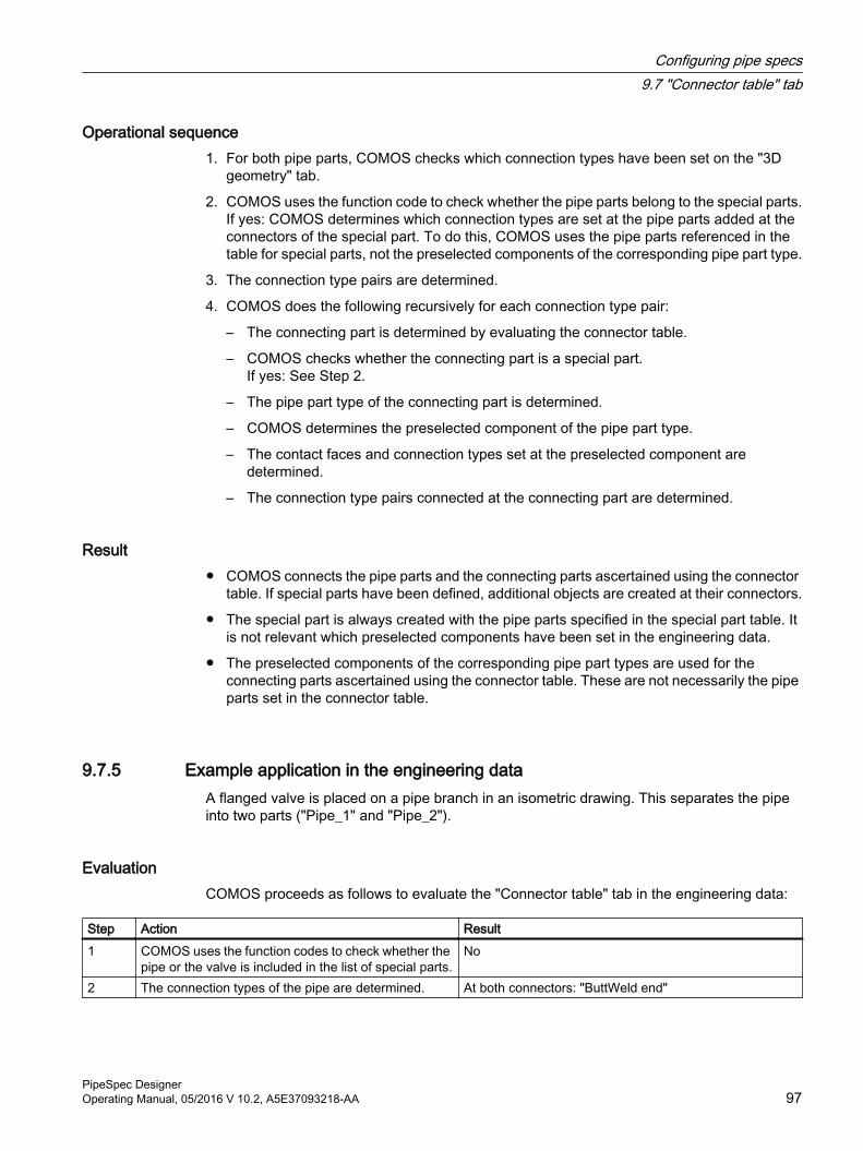
Operational sequence1. For both pipe parts, COMOS checks which connection types have been set on the "3D
geometry" tab.
2. COMOS uses the function code to check whether the pipe parts belong to the special parts.If yes: COMOS determines which connection types are set at the pipe parts added at the connectors of the special part. To do this, COMOS uses the pipe parts referenced in the table for special parts, not the preselected components of the corresponding pipe part type.
3. The connection type pairs are determined.
4. COMOS does the following recursively for each connection type pair:
– The connecting part is determined by evaluating the connector table.
– COMOS checks whether the connecting part is a special part.If yes: See Step 2.
– The pipe part type of the connecting part is determined.
– COMOS determines the preselected component of the pipe part type.
– The contact faces and connection types set at the preselected component are determined.
– The connection type pairs connected at the connecting part are determined.
Result● COMOS connects the pipe parts and the connecting parts ascertained using the connector
table. If special parts have been defined, additional objects are created at their connectors.
● The special part is always created with the pipe parts specified in the special part table. It is not relevant which preselected components have been set in the engineering data.
● The preselected components of the corresponding pipe part types are used for the connecting parts ascertained using the connector table. These are not necessarily the pipe parts set in the connector table.
9.7.5 Example application in the engineering dataA flanged valve is placed on a pipe branch in an isometric drawing. This separates the pipe into two parts ("Pipe_1" and "Pipe_2").
EvaluationCOMOS proceeds as follows to evaluate the "Connector table" tab in the engineering data:
Step Action Result1 COMOS uses the function codes to check whether the
pipe or the valve is included in the list of special parts.No
2 The connection types of the pipe are determined. At both connectors: "ButtWeld end"
Configuring pipe specs9.7 "Connector table" tab
PipeSpec DesignerOperating Manual, 05/2016 V 10.2, A5E37093218-AA 97
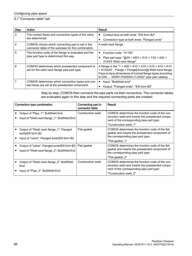
Step Action Result3 The contact faces and connection types of the valve
are determined.● Contact face at both ends: "EN form B2"● Connection type at both ends: "Flanged ends"
4 COMOS checks which connecting part is set in the connector table of the subclass for this combination.
A weld neck flange
5 The function code of the flange is evaluated and the pipe part type is determined this way.
● Function code: "31100"● Pipe part type: "@30 > M23 > A10 > Y30 > A20 >
31XXX Weld neck flange"6 COMOS determines which preselected component is
set for the weld neck flange pipe part type.A flange in the "1 > A50 > A10 > A10 > A15 > A10 > A10 > A10|A20 Flange > Flange[Groove][]-Weld neck flange-Face-to-face dimensions of normal flange types according to DIN ... -WDR1-P245GH (1.0352)" pipe part catalog
7 COMOS determines which connection types and con‐tact faces are set at the preselected component.
● Input: "ButtWeld end"● Output: "Flanged ends", "EN form B2"
Step by step, COMOS then connects the pipe parts via their connectors. The connector tables are evaluated again in this step and the required connecting parts are created:
Connection type combination Connecting part in connector table
Result
● Output of "Pipe_1": ButtWeld End● Input of "Weld neck flange_1": ButtWeld End
Construction weld COMOS determines the function code of the con‐struction weld and inserts the preselected compo‐nent of the corresponding pipe part type:"Construction weld_1"
● Output of "Weld neck flange_1": Flanged ends/EN form B2
● Input of "valve": Flanged ends/EN form B2
Flat gasket COMOS determines the function code of the flat gasket and inserts the preselected component of the corresponding pipe part type:"Flat gasket_1"
● Output of "valve": Flanged ends/EN form B2● Input of "Weld neck flange_2": ButtWeld End
Flat gasket COMOS determines the function code of the flat gasket and inserts the preselected component of the corresponding pipe part type:"Flat gasket_2"
● Output of "Weld neck flange_2": ButtWeld End
● Input of "Pipe_2": ButtWeld End
Construction weld COMOS determines the function code of the con‐struction weld and inserts the preselected compo‐nent of the corresponding pipe part type:"Construction weld_2"
Configuring pipe specs9.7 "Connector table" tab
PipeSpec Designer98 Operating Manual, 05/2016 V 10.2, A5E37093218-AA
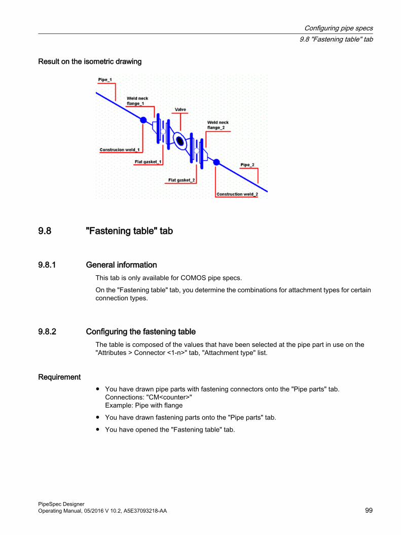
Result on the isometric drawing
9.8 "Fastening table" tab
9.8.1 General informationThis tab is only available for COMOS pipe specs.
On the "Fastening table" tab, you determine the combinations for attachment types for certain connection types.
9.8.2 Configuring the fastening tableThe table is composed of the values that have been selected at the pipe part in use on the "Attributes > Connector <1-n>" tab, "Attachment type" list.
Requirement● You have drawn pipe parts with fastening connectors onto the "Pipe parts" tab.
Connections: "CM<counter>" Example: Pipe with flange
● You have drawn fastening parts onto the "Pipe parts" tab.
● You have opened the "Fastening table" tab.
Configuring pipe specs9.8 "Fastening table" tab
PipeSpec DesignerOperating Manual, 05/2016 V 10.2, A5E37093218-AA 99
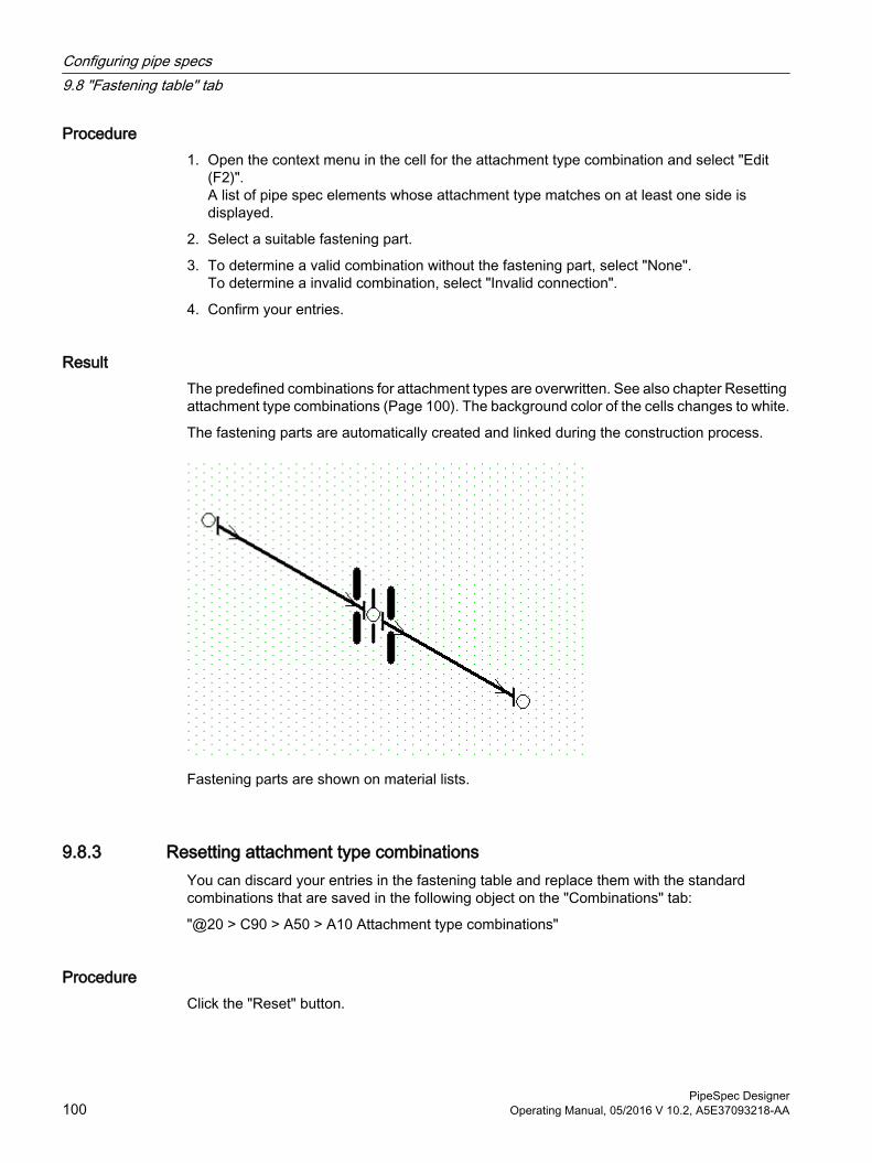
Procedure1. Open the context menu in the cell for the attachment type combination and select "Edit
(F2)".A list of pipe spec elements whose attachment type matches on at least one side is displayed.
2. Select a suitable fastening part.
3. To determine a valid combination without the fastening part, select "None".To determine a invalid combination, select "Invalid connection".
4. Confirm your entries.
ResultThe predefined combinations for attachment types are overwritten. See also chapter Resetting attachment type combinations (Page 100). The background color of the cells changes to white.
The fastening parts are automatically created and linked during the construction process.
Fastening parts are shown on material lists.
9.8.3 Resetting attachment type combinationsYou can discard your entries in the fastening table and replace them with the standard combinations that are saved in the following object on the "Combinations" tab:
"@20 > C90 > A50 > A10 Attachment type combinations"
ProcedureClick the "Reset" button.
Configuring pipe specs9.8 "Fastening table" tab
PipeSpec Designer100 Operating Manual, 05/2016 V 10.2, A5E37093218-AA
See alsoAdding standard combinations (Page 101)
9.8.4 Updating attachment type combinationsThe combinations that you have predefined yourself update automatically.
If you have subsequently added or removed a pipe part from the "Pipe parts" tab, update the standard combinations of the fastening tables manually. COMOS recognizes inconsistencies and corrects these.
ProcedureClick the "Update" button.
9.8.5 Evaluation sequenceThe "Fastening table" tab is evaluated if two pipe parts belonging to the same pipe spec are interconnected in the engineering data.
Procedure1. For both pipe parts, COMOS checks which attachment types have been set on the
"Connector <1-n>" tab.
2. The attachment types are determined.
3. The fastening part is determined for the combinations of both attachment types with the aid of the fastening table.
4. The fastening part is used.
5. Steps 1-4 are executed recursively at every selected fastening part used.
9.8.6 Adding standard combinationsThe standard combinations of attachment types are stored in the following object in the "Default attachment connections" table:
"@20 > C90 > A50 > A10 Attachment type combinations"
● The following standard table is available in the "First attachment type" column and "Second attachment type" column:"Standard tables > Y10 > M23 > A20 > Y10M23N00030 Attachment types"
● The following standard table is available in the "Function code group" column:"Standard tables > Y10 > M23 > A20 > Y10M23N00031 Function code groups"
If you have expanded the standard table, enter the new combinations in the "Attachment type combinations" object.
Configuring pipe specs9.8 "Fastening table" tab
PipeSpec DesignerOperating Manual, 05/2016 V 10.2, A5E37093218-AA 101
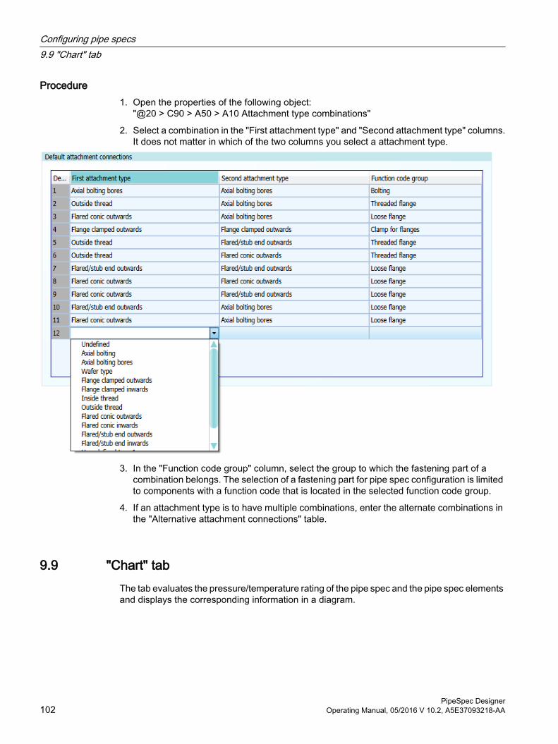
Procedure1. Open the properties of the following object:
"@20 > C90 > A50 > A10 Attachment type combinations"
2. Select a combination in the "First attachment type" and "Second attachment type" columns.It does not matter in which of the two columns you select a attachment type.
3. In the "Function code group" column, select the group to which the fastening part of a combination belongs. The selection of a fastening part for pipe spec configuration is limited to components with a function code that is located in the selected function code group.
4. If an attachment type is to have multiple combinations, enter the alternate combinations in the "Alternative attachment connections" table.
9.9 "Chart" tabThe tab evaluates the pressure/temperature rating of the pipe spec and the pipe spec elements and displays the corresponding information in a diagram.
Configuring pipe specs9.9 "Chart" tab
PipeSpec Designer102 Operating Manual, 05/2016 V 10.2, A5E37093218-AA
9.9.1 Content of the "Chart" tab
Evaluated dataThe diagram evaluates the following data:
● Pipe spec, "Pipe spec limits" tab, "Class use limit" control group: "Rating" table
● Pipe spec elements, "Part attribute" tab, "Pressure/temperature dependency" control group: Tables "T" and "P"
Display
X axis TemperatureY axis PressureLegend Top right-hand corner of the diagram:
● Red: The pipe spec● Other colors: The pipe spec elements
No data availableWhen you click on the tab, even though a pressure/temperature rating has not been defined for the pipe spec and the pipe spec elements, the message "Diagram empty" is displayed.
9.10 "Comments" tab
ProcedureEnter details that additionally document the pipe spec in the "Comments" field.
9.11 "Function" tabSaves data for internal purposes.
Configuring pipe specs9.11 "Function" tab
PipeSpec DesignerOperating Manual, 05/2016 V 10.2, A5E37093218-AA 103
ContentSome of the information on the tab is preconfigured in the database. It has the following attributes:
Attribute Function"Function code" ● Specifies that the base object defines a pipe spec.
● Value: "Pipe spec"● Do not change the value.
"Base object for pipes" ● Defines which base object is used for the first layer of the pipe structure. Overwrites the corresponding project property. See the "COMOS Administration" manual, keyword "Base object for pipe".
● If no link is set, the base object set in the project properties is used."Base object for pipe sec‐tion"
As above.
"PipePart Finder" -"XML file" For an imported pipe spec: The path to the file from which the pipe spec
was read.
Configuring pipe specs9.11 "Function" tab
PipeSpec Designer104 Operating Manual, 05/2016 V 10.2, A5E37093218-AA
Documenting pipe specs 10Example reports
The database contains two ready-to-use examples of evaluation reports which document pipe specs in full:
● A pipe spec report:You can find the pipe spec report on the "Base objects" tab in the Navigator, directly underneath the base object of the pipe spec.
● A component report for each pipe part belonging to the pipe spec:You can find the component report on the "Base objects" tab in the Navigator, directly underneath the base object of the respective pipe spec element.
PipeSpec DesignerOperating Manual, 05/2016 V 10.2, A5E37093218-AA 105

Documenting pipe specs
PipeSpec Designer106 Operating Manual, 05/2016 V 10.2, A5E37093218-AA
Creating a revision of pipe specs 11After you have assembled the pipe spec and assigned all required pipe parts to the pipe spec, you can change the properties of the pipe parts at a later time. You can do this by inheritance, for example, if attributes of a pipe part are changed in the pipe part catalog.
To prevent that a pipe part changes in a pipe spec at a later time, you can create a revision of the pipe spec and its pipe parts. This revision stores all properties of the pipe parts that were present when the pipe class was created.
PipeSpec DesignerOperating Manual, 05/2016 V 10.2, A5E37093218-AA 107

Creating a revision of pipe specs
PipeSpec Designer108 Operating Manual, 05/2016 V 10.2, A5E37093218-AA
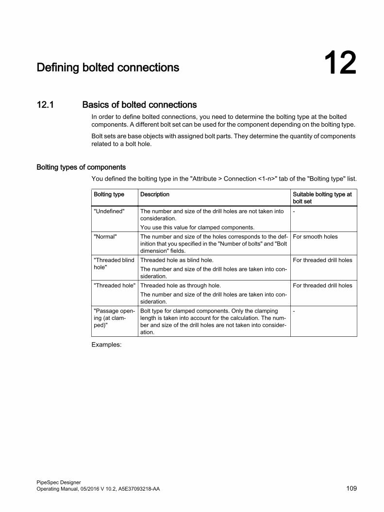
Defining bolted connections 1212.1 Basics of bolted connections
In order to define bolted connections, you need to determine the bolting type at the bolted components. A different bolt set can be used for the component depending on the bolting type.
Bolt sets are base objects with assigned bolt parts. They determine the quantity of components related to a bolt hole.
Bolting types of componentsYou defined the bolting type in the "Attribute > Connection <1-n>" tab of the "Bolting type" list.
Bolting type Description Suitable bolting type at bolt set
"Undefined" The number and size of the drill holes are not taken into consideration.You use this value for clamped components.
-
"Normal" The number and size of the holes corresponds to the def‐inition that you specified in the "Number of bolts" and "Bolt dimension" fields.
For smooth holes
"Threaded blind hole"
Threaded hole as blind hole. The number and size of the drill holes are taken into con‐sideration.
For threaded drill holes
"Threaded hole" Threaded hole as through hole.The number and size of the drill holes are taken into con‐sideration.
For threaded drill holes
"Passage open‐ing (at clam‐ped)"
Bolt type for clamped components. Only the clamping length is taken into account for the calculation. The num‐ber and size of the drill holes are not taken into consider‐ation.
-
Examples:
PipeSpec DesignerOperating Manual, 05/2016 V 10.2, A5E37093218-AA 109
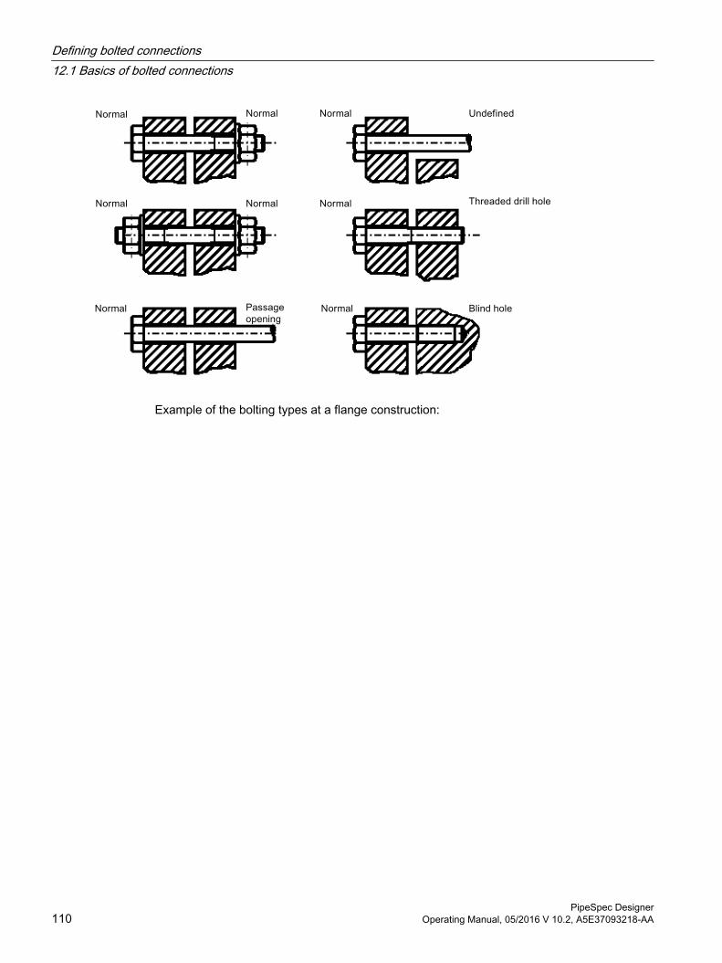
Example of the bolting types at a flange construction:
Defining bolted connections12.1 Basics of bolted connections
PipeSpec Designer110 Operating Manual, 05/2016 V 10.2, A5E37093218-AA
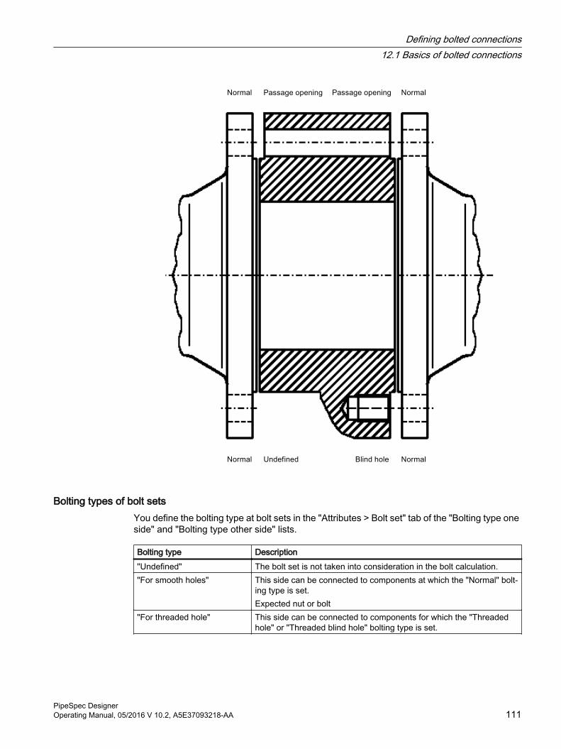
Bolting types of bolt setsYou define the bolting type at bolt sets in the "Attributes > Bolt set" tab of the "Bolting type one side" and "Bolting type other side" lists.
Bolting type Description"Undefined" The bolt set is not taken into consideration in the bolt calculation."For smooth holes" This side can be connected to components at which the "Normal" bolt‐
ing type is set.Expected nut or bolt
"For threaded hole" This side can be connected to components for which the "Threaded hole" or "Threaded blind hole" bolting type is set.
Defining bolted connections12.1 Basics of bolted connections
PipeSpec DesignerOperating Manual, 05/2016 V 10.2, A5E37093218-AA 111
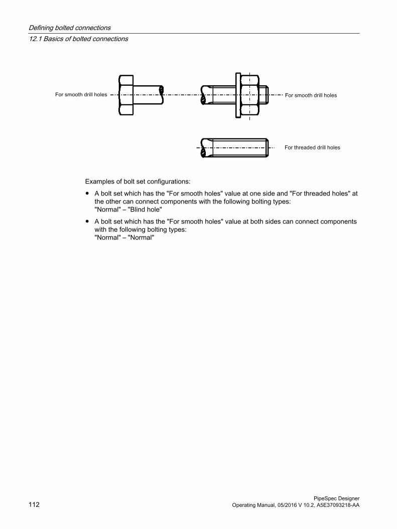
Examples of bolt set configurations:
● A bolt set which has the "For smooth holes" value at one side and "For threaded holes" at the other can connect components with the following bolting types:"Normal" – "Blind hole"
● A bolt set which has the "For smooth holes" value at both sides can connect components with the following bolting types:"Normal" – "Normal"
Defining bolted connections12.1 Basics of bolted connections
PipeSpec Designer112 Operating Manual, 05/2016 V 10.2, A5E37093218-AA
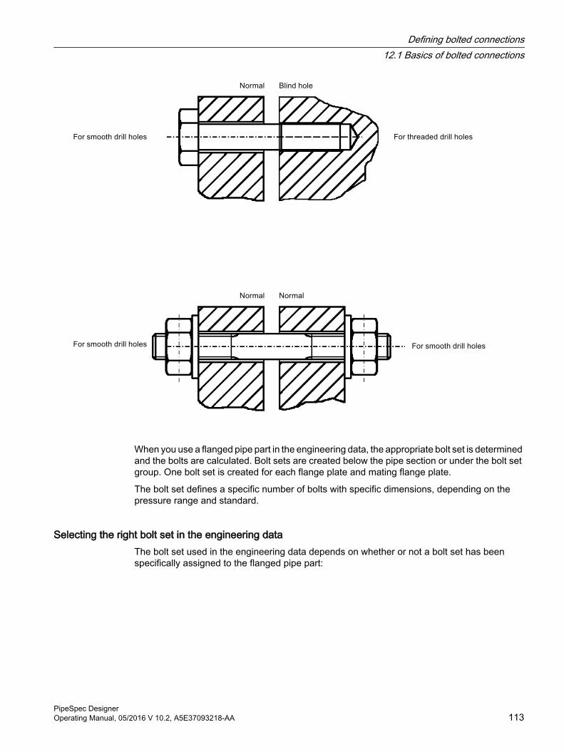
When you use a flanged pipe part in the engineering data, the appropriate bolt set is determined and the bolts are calculated. Bolt sets are created below the pipe section or under the bolt set group. One bolt set is created for each flange plate and mating flange plate.
The bolt set defines a specific number of bolts with specific dimensions, depending on the pressure range and standard.
Selecting the right bolt set in the engineering dataThe bolt set used in the engineering data depends on whether or not a bolt set has been specifically assigned to the flanged pipe part:
Defining bolted connections12.1 Basics of bolted connections
PipeSpec DesignerOperating Manual, 05/2016 V 10.2, A5E37093218-AA 113
No bolt set assigned (default procedure):
● The pipe spec and nominal diameter of the pipe part are determined.
● COMOS checks which bolt sets are available in the pipe spec for the nominal diameter:
– If a matching bolt set is found, it is used.
– With several matching bolt sets: The bolt set that was set as the preselected component for the nominal diameter is used. See also chapter Defining preselected components (Page 86).
See also chapter Using bolt sets in pipe specs (Page 120).
Bolt set assigned:
● If a bolt set has been assigned to the pipe part in the pipe part catalog or at the pipe spec element, it is used.See also chapter Specifying bolted connections at pipe parts (Page 117).
Bolts calculationThe data required to calculate the bolted connections is taken from the following sources:
● The geometry standards for the flanges
● The geometry standards for the bolt parts
The type of bolted connection set at the flange pipe part determines which algorithm COMOS uses to calculate the bolt lengths.
12.2 Creating bolt sets
Requirement● You are familiar with the procedure to prepare for creating and managing pipe specs. See
also chapter Basic procedure for preparation (Page 15).When creating bolt sets, this means:
– The standard tables required for bolt parts are complete.See also chapter Standard tables for bolt parts and bolt sets (Page 117).
– The important geometry standards for bolt parts, flanges, and gaskets are included in the "standard geometry tables" standard catalog.See also chapter Managing the "standard geometry tables" standard catalog (Page 21).
– The pipe part catalog contains bolt parts, flanges, and gaskets.See also chapter Administering pipe part catalogs (Page 27).
● You have selected the "Base objects" tab in the Navigator.
Defining bolted connections12.2 Creating bolt sets
PipeSpec Designer114 Operating Manual, 05/2016 V 10.2, A5E37093218-AA
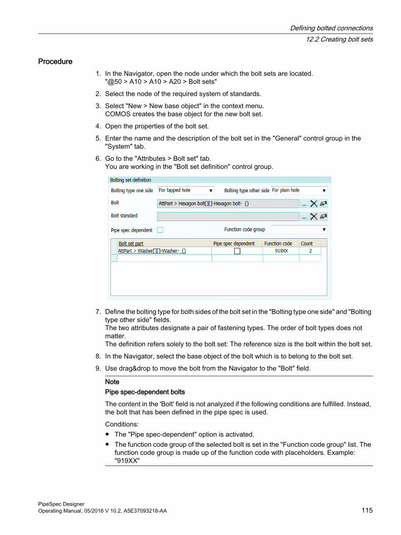
Procedure1. In the Navigator, open the node under which the bolt sets are located.
"@50 > A10 > A10 > A20 > Bolt sets"
2. Select the node of the required system of standards.
3. Select "New > New base object" in the context menu.COMOS creates the base object for the new bolt set.
4. Open the properties of the bolt set.
5. Enter the name and the description of the bolt set in the "General" control group in the "System" tab.
6. Go to the "Attributes > Bolt set" tab.You are working in the "Bolt set definition" control group.
7. Define the bolting type for both sides of the bolt set in the "Bolting type one side" and "Bolting type other side" fields.The two attributes designate a pair of fastening types. The order of bolt types does not matter. The definition refers solely to the bolt set: The reference size is the bolt within the bolt set.
8. In the Navigator, select the base object of the bolt which is to belong to the bolt set.
9. Use drag&drop to move the bolt from the Navigator to the "Bolt" field.
NotePipe spec-dependent bolts
The content in the 'Bolt' field is not analyzed if the following conditions are fulfilled. Instead, the bolt that has been defined in the pipe spec is used.
Conditions:● The "Pipe spec-dependent" option is activated.● The function code group of the selected bolt is set in the "Function code group" list. The
function code group is made up of the function code with placeholders. Example: "919XX"
Defining bolted connections12.2 Creating bolt sets
PipeSpec DesignerOperating Manual, 05/2016 V 10.2, A5E37093218-AA 115
10.Set a reference to a geometry table for bolts in the "Bolt standard" field.
NoteNo reference in the "Bolt standard" field
If you do not enter a reference in the "Bolt standard" field, a reference to a geometry table for bolts must exist at the base object of the bolt at the following location:
Pipe part catalog, base object of the bolt, "3D geometry" tab
11.In the Navigator, select the base object of the nut or washer which is to belong to the bolt set.
12.Drag&Drop the nut from the Navigator to the "Bolt set definition" control group, the "Bolt set part" column of the table.
13.Optionally: Activate the "Pipe spec dependent" option.If you assign a bolt set to a pipe part or pipe spec element and the "Pipe spec dependent" option is deactivated at the bolt set, the assigned bolt set is generated during bolt calculation. Otherwise, a bolt set that was defined in the pipe spec is generated.
NotePipe spec-dependent bolt set parts
The respective row in the "Bolt set part" column is not analyzed if the following conditions are fulfilled. Instead, the bolt set part that has been defined in the pipe spec is used.
Conditions:● The "Pipe spec-dependent" option is activated in the table.● The function code group of the selected bolt set part is set in the "Function code" cell.
The function code group is made up of the function code with placeholders. Example: "919XX"
See also chapter "Fastening table" tab (Page 99).
14.Enter the number of nuts in the "Quantity" column of the upper table.Example: "2"Meaning: 2 nuts per bolt, that is, 2 times n nuts in total.
15.Go to the "Attributes > 3D Geometry" tab.
16.Check that the "Bolt set" entry is selected in the "Function code" list.
17.Save your entries.
ResultYou can use the bolt sets in pipe specs or assign it fixed to components.
See also chapter Basics of bolted connections (Page 109).
Defining bolted connections12.2 Creating bolt sets
PipeSpec Designer116 Operating Manual, 05/2016 V 10.2, A5E37093218-AA
12.3 Specifying bolted connections at pipe parts
RequirementYou have already prepared bolt sets in the base data. See also chapter Defining bolted connections (Page 109).
Procedure1. Open the properties of a bolted pipe part or pipe spec element.
2. Select the "Connection <1-n>" tab , which contains the control groups "Information - First bolt circle" and "Information - Second bolt circle".
3. Select the bolt type in the control group "Information - First bolt circle".The combination of the settings at the bolt set and the settings at the first and second bolt circle of a pipe part makes it possible to determine two different bolt sets for a connection, one of which is used. Possible values: See chapter Basics of bolted connections (Page 109).
4. Ensure that the calculation formulas are entered correctly and completely in the fields for the specification of the bolt set. See also chapter Determining the component geometry of a pipe part (Page 28).Alternatively, you can enter the values manually without having them calculated.
5. Explicitly assign a bolt set to the pipe part or have a matching bolt set selected via the pipe spec.
– See also chapter Assigning the bolt set to a pipe part (Page 122).
– See also chapter Adding a bolt set to the pipe spec (Page 121).
6. To define two bolt types at the connector of the pipe part, proceed as described in the control group "Information - Second bolt circle".The order of the definition of bolt types does not matter.
ResultThe defined bolt sets are generated during the bolt calculation.
12.4 Standard tables for bolt parts and bolt setsYou need the following standard tables when you use bolt parts and bolt sets.
Standard table for function codes"Standard tables > Y10 > M23 > A10 > Y10M23N00001 Function code" node.
The standard table is used in the pipe part catalog, in the "3D geometry" tab.
See also chapter Standard table for function codes (Page 54).
Defining bolted connections12.4 Standard tables for bolt parts and bolt sets
PipeSpec DesignerOperating Manual, 05/2016 V 10.2, A5E37093218-AA 117
Standard table of standards for screws and nuts● Standard tables in the database:
– DIN/EN:"Standard tables > Y10 > M20 > Y30 > A10 > 1 > B10 > B40 Bolt standards"
– ANSI/ASME:
– "Standard tables > Y10 > M20 > Y30 > A10 > 10 > B10 > B40 Bolt standards"
● The standard table is used in the following places:
– As a parameter in the standardizations, in the "Attributes > Define characteristics" tab.
– In the properties of screws and nuts, "Attributes > Part description" tab.
Standard table of dimensions of screws and nuts● Standard tables in the database:
– DIN/EN:"Standard tables > Y10 > M20 > Y30 > A10 > 1 > B40 > A10 Bolt dimensions nuts and bolts"
– ANSI/ASME:"Standard tables > Y10 > M20 > Y30 > A10 > 10 > B40 > A10 Bolt dimensions"
● Similar to the standard table for nominal diameters, the following applies:
– New dimensions are appended to the end of the list.
– Do not move or delete existing entries.
● The standard table is used in the following places:
– In the "standard geometry tables" standard catalog.
– At the bolts, nuts, and washers in the template of the pipe part catalog under the following node:"@30 > M23 > A50 > A10 > Pipe part Catalog template"
Defining bolted connections12.4 Standard tables for bolt parts and bolt sets
PipeSpec Designer118 Operating Manual, 05/2016 V 10.2, A5E37093218-AA
Standard table for screw lengths● Standard tables in the database:
– DIN/EN:"Standard tables > Y10 > M20 > Y30 > A10 > 1 > B40 > A20 Bolt length"
– ANSI/ASME"Standard tables > Y10 > M20 > Y30 > A10 > 10 > B40 > A20 Bolt length"
Similar to the standard table for nominal diameters, the following applies:
– New values are appended to the end of the list.
– Do not move or delete existing entries.
● The standard table is used in the following places:
– In the "standard geometry tables" standard catalog"@30 > M23 > A10 > Y30 > A10 Standard geometry tables"
– At the bolts, nuts, and washers in the pipe part catalog.
Standard table of strength grades for screws and nuts● Standard table in the database:
– DIN/EN:"Standard tables > Y10 > M20 > Y30 > A10 > 1 > B40 > A30 Strength grade bolts acc DIN2507""Standard tables > Y10 > M20 > Y30 > A10 > 1 > B40 > A40 Strength grade nuts acc ISO 898-2"
– ANSI/ASME:"Standard tables > Y10 > M20 > Y30 > A10 > 10 > B40 > A30 Property classes of bolts according to ASME""Standard tables > Y10 > M20 > Y30 > A10 > 10 > B40 > A40 Property classes of nuts according to ASME"
● The standard table is used in the following places:
– In the PipeSpec Designer in the "Characteristics" tab.
– In the properties of screws and nuts, "Attributes > Part description" tab.
Standard table for bolted types● Standard table in the database:
"Standard tables > Y10 > M23 > A20 > Y10M23N00028 Bolted types"
● The standard table is used in the flanges of the pipe part catalog, in the "3D geometry" tab.
Defining bolted connections12.4 Standard tables for bolt parts and bolt sets
PipeSpec DesignerOperating Manual, 05/2016 V 10.2, A5E37093218-AA 119
12.5 Using bolt sets in pipe specs
12.5.1 Overview of the work sequence
Requirement● The required bolt sets are available in the base data. See also chapter Creating bolt sets
(Page 114).
● The information for the bolt sets is stored in the "Attributes > Connection <1-n>" tab at the pipe parts in the pipe part catalog or at the pipe spec elements. The control groups of the required bolt circles are completely filled except for the "Bolt set" field. See also chapter Specifying bolted connections at pipe parts (Page 117).
Workflow1. Define the characteristics for the strength grades of bolts and nuts in the pipe spec.
See also chapter Defining the strength grades of screws and nuts (Page 120).
2. Add the bolt set to the pipe spec and define the nominal diameter range within which the bolt set is available.See also chapter Adding a bolt set to the pipe spec (Page 121).
3. Optional: Add the bolt parts of the bolt set to the pipe spec and define the dimensions in which the bolt parts of the bolt set are available.See also chapter Adding screw parts to the pipe spec (Page 121).
4. Optional: Assign the bolt set to a flanged pipe part, either in the pipe part catalog or in the pipe spec.See also chapter Assigning the bolt set to a pipe part (Page 122).
12.5.2 Defining the strength grades of screws and nuts
RequirementYou have loaded the pipe spec in which you wish to use the bolt set in the PipeSpec Designer.
Procedure1. Select the "Characteristics" tab.
You are working in the "Class parameters" control group.
2. Select the strength for screws and nuts in the list of the same name.
3. Save your entries.
Defining bolted connections12.5 Using bolt sets in pipe specs
PipeSpec Designer120 Operating Manual, 05/2016 V 10.2, A5E37093218-AA
12.5.3 Adding a bolt set to the pipe specYou can add several bolt sets with different nominal diameters for the same fastening type to a pipe spec.
Requirements● You have loaded the pipe spec in which you wish to use the bolt set in the
PipeSpec Designer.
● The "Base objects" tab is open in the Navigator.
Procedure1. Go to the "Components" tab.
2. In the Navigator, open the "@50 > A10 > A10 > A20 Bolt sets" node.
3. Drag&drop the required bolt set from the Navigator to the "Components" tab.
4. Save your entries.
12.5.4 Adding screw parts to the pipe spec
BackgroundThe evaluation reports for the documentation of the pipe spec only contain information about the bolt parts of the bolt set if the bolt parts have been added to the pipe spec.
Requirements● You have loaded the pipe spec in which you wish to use the bolt set in the
PipeSpec Designer.
● The "Base objects" tab is open in the Navigator.
Procedure1. Select the base object of the bolt set in the Navigator.
2. Open the properties of the bolt set and click the "Attributes > Bolt set" tab.All bolt parts which are part of the bolt set are displayed in the tables of the "Bolt set part" control group.
Defining bolted connections12.5 Using bolt sets in pipe specs
PipeSpec DesignerOperating Manual, 05/2016 V 10.2, A5E37093218-AA 121
3. To add the bolts and bolt parts of the bolt set to the pipe spec, proceed as follows:
– Select a bolt part from the table in the "Bolt set definition" control group.
– Select "Navigate > Object" from the context menu.The base object is selected in the Navigator under the open pipe part catalog.
– Drag the base object of the bolt part from the Navigator with drag&drop to the "Pipe parts" tab of the PipeSpec Designer.The bolt part is assigned to the pipe spec. In the component table, the bolt parts are grouped under the node with the function code "XXXXX".The columns "Nominal diameter from" and "Nominal diameter to" show you which upper limitand which lower limit the standardization gives for the bolt parts.
– To limit the specified upper limit and lower limit, click the "Nominal diameter from" and "Nominal diameter to" columns and change the dimension in the list.
4. Change to the "Nominal diameters > XXXXX" tab.
5. Refine the dimensions in which the bolt parts are available in the "Nominal diameter range" control group.
6. Save your entries.
See also"Nominal diameters" tab: (Page 84)
12.5.5 Assigning the bolt set to a pipe part
RequirementThe required bolt set is displayed in the "Base objects" tab in the Navigator.
Procedure1. If the bolt set is to be used all the time regardless of the pipe spec to which the pipe part
belongs, proceed as follows:
– Navigate to the base object of the pipe part in the pipe part catalog.
– Open the properties.
If the bolt set is to be used for a certain pipe spec only, navigate to the base object of the pipe spec.
– Open the properties of the pipe spec element.
2. Click the "Attributes > Connector <Counter>" tab, which describes the connection of the bolted end.
3. Drag&Drop the base object of the bolt set to the "Bolt set" field.
4. Save your entries.
Defining bolted connections12.5 Using bolt sets in pipe specs
PipeSpec Designer122 Operating Manual, 05/2016 V 10.2, A5E37093218-AA
Rules for assigned bolt sets
Connection RuleFlange - flange Both bolt sets must be identical.
The bolt set first found is used.Flange - valve - flange The bolt set of the valve is used.Contiguous flange group with clamp part The bolt set of the clamp part is used.
12.5.6 Creating bolt sets
RequirementYou have linked pipe parts with one of the following attachment types:
● Bolted connection
● Hole for bolted connection
● Wafer type
ProcedureYou can find additional information on this topic in the "Isometrics" manual, keyword "Calculating bolts".
ResultWhen you calculate a flanged pipe part in the engineering data, the following happens:
● The suitable bolt set in the pipe spec is determined.
● The bolt set is calculated.
● The bolt set is created below one of the bolted parts or below the bolt set group.
– The placement location of the bolt on the isometry is assigned to the bill of materials via the item number.
– A unique key is generated for each bolt set. The item number of the gasket is at the first position, followed by item numbers of the other components. The item numbers are listed in ascending order.
– If a component is placed on two isometries, the "#" character is used for the connected component if it does not have an item number.
Viewing the properties of the calculated bolt setYou can find out more about the result of the calculation in the properties of the bolt set in the "Attributes > For bolt calculation" tab.
Defining bolted connections12.5 Using bolt sets in pipe specs
PipeSpec DesignerOperating Manual, 05/2016 V 10.2, A5E37093218-AA 123
The following information will be displayed:
● "Bolting definition" control group
– The control group contains information on the bolt and the associated parts, such as the nut and washer.
– The number of bolts used and the calculated length of the bolts is shown. See also chapter Algorithm for calculating the screw length (Page 150).
● "Used bolt parts" control groupThe control group shows which bolt parts are used with which properties in the engineering data.
See alsoDefining bolted connections (Page 109)
12.5.7 Using a bolt set group
You can use bolt set groups to manage bolt sets via the pipe spec.
Bolt set groups have the following advantages:
● All bolt sets of a connection are sorted under the bolt set group.
● If you remove the connection of two pipe parts, the group and all associated bolt sets are automatically deleted.
● The bolted connection is visible in the Navigator even before the calculation.
12.5.7.1 Adding a bolt set group to the pipe specSelect the bolt set group you are using.
● If you use the predefined fastening types, you only need the bolt set group "A10 bolted connection", which already exists in the database.
● If you define new fastening types, create new bolt set groups based on the following template:"@30 > M23 > A50 > A10 > A10 > A10 > B40 > A30 Bolted connection"
You add attachment types in the following standard table:
"Standard tables > Y10 > M23 > A20 > Y10M23N00030 Attachment types"
Using an existing bolt set group1. Open a pipe spec from the "Administrator > Base data > > Pipe specs" menu.
2. Open the "Pipe parts" tab.
3. Navigate to the following node:"@50 > A10 > A10 > A10 > 1 > B40 > A30 > A10 > A10 Bolted connection"
4. Drag&drop the object onto the "Pipe parts" tab.
Defining bolted connections12.5 Using bolt sets in pipe specs
PipeSpec Designer124 Operating Manual, 05/2016 V 10.2, A5E37093218-AA
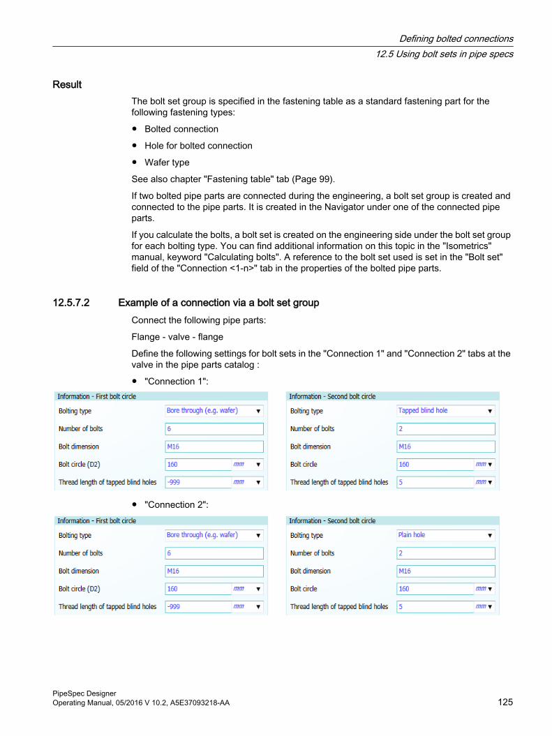
ResultThe bolt set group is specified in the fastening table as a standard fastening part for the following fastening types:
● Bolted connection
● Hole for bolted connection
● Wafer type
See also chapter "Fastening table" tab (Page 99).
If two bolted pipe parts are connected during the engineering, a bolt set group is created and connected to the pipe parts. It is created in the Navigator under one of the connected pipe parts.
If you calculate the bolts, a bolt set is created on the engineering side under the bolt set group for each bolting type. You can find additional information on this topic in the "Isometrics" manual, keyword "Calculating bolts". A reference to the bolt set used is set in the "Bolt set" field of the "Connection <1-n>" tab in the properties of the bolted pipe parts.
12.5.7.2 Example of a connection via a bolt set groupConnect the following pipe parts:
Flange - valve - flange
Define the following settings for bolt sets in the "Connection 1" and "Connection 2" tabs at the valve in the pipe parts catalog :
● "Connection 1":
● "Connection 2":
Defining bolted connections12.5 Using bolt sets in pipe specs
PipeSpec DesignerOperating Manual, 05/2016 V 10.2, A5E37093218-AA 125
ResultAfter you have connected the pipe parts, a bolt set group is created. If you have performed the bolt calculation, the following bolt sets are generated:
● One for the "normal" bolt type that connects all three pipe parts with one another
● One for the "Threaded blind hole" bolt type, which connects the valve with the flange on one side
● One for the "Normal" bolt type, which connects the valve with the flange on the other side
12.5.7.3 Deleting a bolt set group
ProcedureTo delete a bolt set group, remove the connection of the pipe parts that are connected to the bolt set group.
ResultThe bolt set group and all associated bolt sets are deleted.
If the bolt sets in a group connect three pipe parts and you only remove the connection between two pipe parts, the bolt set of the connection that you have not separated will also be deleted. See also chapter Example of a connection via a bolt set group (Page 125).
Defining bolted connections12.5 Using bolt sets in pipe specs
PipeSpec Designer126 Operating Manual, 05/2016 V 10.2, A5E37093218-AA
P&ID 3D pipe part catalog interaction 13Aim
If the P&ID catalog is linked to the pipe part catalog, the users already have the option to work in the P&ID module based on the pipe specs.
The link also creates a seamless transition between the individual project phases: from P&ID engineering through the creation of isometric drawings and beyond to 3D engineering.
PrincipleIf the P&ID catalog is linked to the pipe part catalog, P&ID engineering is carried out based on pipe specs:
● COMOS starts a pipe spec mapping as soon as a user assigns a pipe spec and nominal diameter to a P&ID object.
● The user selects a suitable object from a range of possible objects from the pipe part catalog.
● The P&ID user continues to work with the P&ID object.
● The 3D-capable pipe part catalog object is managed as an implementation in the background. It can be used for the rest of the planning, e.g. to create isometrics.
● The symbol of the pipe part catalog object is issued on the P&ID.
13.1 Requirements for linking P&ID and 3D pipe part catalogBefore you link the P&ID catalog to the pipe part catalog, check that the following requirements have been met:
● The pipe part catalog has been imported into the base project.
● The base project features a standard table for the P&ID function codes.
● The base project features a standard table for the function codes.
● The project must have certain project parameters.See also chapter Configuring project properties for interaction between P&ID catalog and pipe part catalog (Page 132).
● The P&ID base objects must have certain properties and attributes. See also chapter Configuring P&ID base objects (Page 133).
● The pipe part catalog base objects must have certain properties and attributes. See also chapter Configuring pipe part catalog base objects (Page 134).
PipeSpec DesignerOperating Manual, 05/2016 V 10.2, A5E37093218-AA 127
13.2 Technical details
13.2.1 Link between P&ID and pipe part catalog
Implementation● A P&ID function code from the following standard table is assigned to each P&ID base
object:"Standard tables > @40 > Y00 > A10 > A90 > Y00N00217 Function code for P&ID"
● The database features a standard table grouping the function codes of the objects from the pipe part catalog."Standard tables > Y10 > M23 > A10 > Y10M23N00001 Function code"
● A function code from this standard table is assigned to each pipe part catalog base object.
● The P&ID function codes and the function codes are assigned to one another via the link code entered in the standard table for function codes.There can be any number of suitable pipe part catalog objects for each P&ID pipe part category (ratio 1:N).
● Every P&ID object has attributes that save the pipe spec and nominal diameter.
● When a user assigns a pipe spec and a nominal diameter to a P&ID engineering object, COMOS starts a pipe spec mapping based on the pipe spec, the nominal diameter, and the P&ID function code.
● In the course of pipe spec mapping, the P&ID object is assigned an implementation pointer to a pipe part catalog object.
See alsoThe pipe spec mapping sequence (Page 128)
Result of pipe spec mapping (Page 129)
13.2.2 The pipe spec mapping sequenceWhen the pipe spec or the nominal diameter of a pipe part is changed, this may initiate the pipe spec mapping. A search is conducted for a new matching component.
Function description1. COMOS reads out the pipe spec set at the P&ID object and searches for the base object
of the corresponding pipe spec.
2. COMOS reads out the P&ID function code of the P&ID object.
3. COMOS searches the standard table for function codes and compares the values or masks entered in the "Value 2" column with the function code of the P&ID object.
P&ID 3D pipe part catalog interaction13.2 Technical details
PipeSpec Designer128 Operating Manual, 05/2016 V 10.2, A5E37093218-AA
4. For all entries with a matching value:
– COMOS searches for all pipe spec elements with a matching function code from the pipe spec.
– For the pipe spec elements, COMOS checks whether the nominal diameter set at the P&ID object corresponds to the nominal diameter range of these pipe spec elements.When this condition is met, COMOS makes the pipe spec elements available to the user for selection during pipe spec mapping.
5. The user selects the required object from the list of possible objects from the pipe part catalog.
13.2.3 Result of pipe spec mapping● The P&ID object is retained as the request. The P&ID user continues to work with the P&ID
object.
● The pipe part catalog object selected by the user is created in the engineering data as an implementation underneath the P&ID object.Users can move the pipe part catalog object to a different location later on in the engineering process.
● The P&ID object gets an implementation pointer to the pipe part catalog object.
● The connection type of the P&ID object is determined by the connection type of the pipe part catalog object.
● The nominal pressure at the pipe is linked with the pipe spec nominal pressure.
● The symbol of the pipe part catalog object is used on the P&ID. However, the P&ID object remains the report object.
13.3 Overview of the configuration sequenceTo link the P&ID catalog to the pipe part catalog, proceed as follows:
1. Standard table for the function codes of P&ID objects: Enter the P&ID function codes.See Adding P&ID function codes (Page 130).
2. Standard table for the function codes of the pipe part catalog objects: Enter the link code for the P&ID objects.See Linking the P&ID function code to the function codes (Page 131).
P&ID 3D pipe part catalog interaction13.3 Overview of the configuration sequence
PipeSpec DesignerOperating Manual, 05/2016 V 10.2, A5E37093218-AA 129
3. Project properties: Configure the following categories:
– "Process engineering > PipeSpec Manager"
– "Process engineering > PipeSpec Designer"
See Configuring project properties for interaction between P&ID catalog and pipe part catalog (Page 132).
4. Configure the properties of the P&ID base objects. See Configuring P&ID base objects (Page 133).Configure the properties of the pipe part catalog base objects. See Configuring pipe part catalog base objects (Page 134).
13.4 Adding P&ID function codesEvery entry in the standard table represents a P&ID component category. The entry defines the function code of the component category. You can enter as many component categories as you like in the standard table.
Requirements● The base project is open.
● The standard table containing the P&ID function codes is open."Standard tables > @40 > Y00 > A10 > A90 > Y00N00217 Function code for P&ID"
Procedure1. Create a new standard table entry.
2. "Name" property: Enter the name of the component category.
3. "Description" property: Enter the description of the component category.
4. "Value 1" property: Enter the abbreviation of the component category.
– The ID code is used as a link code in the standard table for function codes. In other words, COMOS searches the standard table for function codes using the ID code.
– You can work with the following placeholder character: "*"COMOS then searches the standard table for function codes with a LIKE comparison.
Example for P&ID function code with placeholdersAbbreviation in the standard table for P&ID function codes: "V2W***"
All entries in the standard table for function codes whose link code in the "Value 2" column is six characters in length and starts with "V2W" count as hits (for example: " V2WARM", "V2WSVA", "V2WORI").
P&ID 3D pipe part catalog interaction13.4 Adding P&ID function codes
PipeSpec Designer130 Operating Manual, 05/2016 V 10.2, A5E37093218-AA
13.5 Linking the P&ID function code to the function codesEvery entry in the standard table represents a pipe part catalog component category. The entry defines the function code of the component category.
NoteOnly configure the "Value 2" column
Only change the "Value 2" column.
Other columns should only be changed after consulting your customer representative.
Requirement● The base project is open.
● The standard table for pipe part catalog function codes is open."Standard tables > Y10 > M23 > A10 > Y10M23N00001 Function code"
● The standard table for P&ID function codes is open."Standard tables > @40 > Y00 > A10 > A90 > Y00N00217 Function code for P&ID"
Procedure1. Select an entry.
2. Click twice with the left mouse button in the field for the "Value 1" column, so that the mouse pointer is positioned in the cell.
3. Copy the value from the "Value 1" column - the link code - to the clipboard.
4. Go to the standard table for function codes and select the entry for the corresponding component category.
5. Click twice with the left mouse button in the field for the "Value 2" column, so that the mouse pointer is positioned in the cell.
6. Paste the link code from the clipboard into the "Value 2" column.
ExampleTo link an eccentric reducer from the P&ID catalog to an eccentric reducer from the pipe part catalog, proceed as follows:
1. In the standard table for the P&ID function codes, go to the following entry:
– Name: "A070"
– Description: "Excentric reducer"
– Value 2: "R"
2. Copy the value from the "Value 2" column to the clipboard.
P&ID 3D pipe part catalog interaction13.5 Linking the P&ID function code to the function codes
PipeSpec DesignerOperating Manual, 05/2016 V 10.2, A5E37093218-AA 131
3. In the standard table for the pipe part catalog function codes, search for the following entry:
– Name: "A780"
– Description: "Excentric reducer"
– Value 1: "51200"
4. Paste the value from the clipboard into the "Value 2" column.
See alsoStandard table for function codes (Page 54)
13.6 Configuring project properties for interaction between P&ID catalog and pipe part catalog
NoteWhen changing the defaults, make sure that you adjust the scripts
When you enter values in the project properties which differ from the default values set in the base project in the database ("Process engineering > PipeSpec Manager" category, "Link between P&ID and pipe part catalog" control group), the following effects will result:
You must modify all scripts which, for performance reasons, use fixed attribute names instead of accessing the project properties. You will find a list of these scripts in Inheritance of the nominal diameters and pipe spec (Page 154).
Requirements● The base project is open.
● The properties of the base project are open.
Procedure1. Select the "Process engineering > PipeSpec Manager" category.
2. Optional: Change the defaults in the "Link between P&ID and pipe part catalog" control group. See also chapter Project properties "PipeSpec Manager" category (Page 160).
P&ID 3D pipe part catalog interaction13.6 Configuring project properties for interaction between P&ID catalog and pipe part catalog
PipeSpec Designer132 Operating Manual, 05/2016 V 10.2, A5E37093218-AA
13.7 Configuring P&ID base objects
13.7.1 WorkflowThe P&ID catalog supplied with the database contains all settings necessary for the link between the P&ID catalog, the pipe part catalog, and 3D.
When you have changed the P&ID catalog as follows, make sure that all objects have the settings required for the link:
● You have created your own P&ID catalog.
● You have made major changes or additions to the catalog supplied with the database.
ProcedureTo do this, proceed as follows for every P&ID base object:
1. Check whether the P&ID base object is defined as a request:Properties, "System settings" tab, "Implement requests" control group: The "Request" option is activated.
2. If the P&ID base object has the "3D geometry" tab, delete or rename it.Reason: The 3D functionality should not be derived from the P&ID object but instead from the pipe part catalog implementation.
3. Check the attribute for the P&ID function code.See also chapter Checking the attribute for the P&ID function code (Page 133).
4. Optional: If the nominal pressure of the pipe spec is to be applied to the P&ID pipe, you must link the attribute for the nominal pressure.See also chapter Link for the "Nominal pressure" attribute (Page 157).
5. Deactivate the standard checks for the implementation link carried out automatically by COMOS through the "IsImplementationValid(Device)" and "OnImplementationSet(Oldvalue)" script blocks.See also chapter Deactivating the standard check with "IsImplementationValid" and "OnImplementationSet" (Page 157).
13.7.2 Checking the attribute for the P&ID function code
RequirementYou know which attribute the P&ID function code is saved in. You can check which attribute this is in the project properties. See also chapter Configuring project properties for interaction between P&ID catalog and pipe part catalog (Page 132).
P&ID 3D pipe part catalog interaction13.7 Configuring P&ID base objects
PipeSpec DesignerOperating Manual, 05/2016 V 10.2, A5E37093218-AA 133
Procedure1. Open the properties of the P&ID base object.
You can find the P&ID base objects under the following node in the database:"@30 > M00 > A50 > Device structures"
2. Check whether the "Function code" attribute is placed in the tab and has the same name as specified in the project properties in the "Attribute for P&ID function code" field. Create the attribute at the P&ID base object if it does not exist yet.
3. Check whether the standard table for P&ID function codes defined in the project properties has been assigned to the attribute.Assign the standard table, if necessary.
4. Check whether a feasible P&ID function code has been set at the attribute.Set one if necessary.Repeat these steps for each P&ID base object.
5. Save your entries.
13.7.3 Implementing branches
Initial situationA branch has been drawn in on a P&ID which is implemented via a dynamic connector and not via a branch part, such as a tee, for example.
Pipe spec mapping for branches without branch part If you have drawn in a branch on the P&ID without a branch part such as a tee, for example, you can still store a corresponding pipe part catalog object at the associated connector for the detail engineering.
COMOS interprets the dynamic connector as a branch. With pipe spec mapping, you can select a pipe part catalog object for the detail engineering. COMOS determines the branch part from the branch table or through function code 71xxx. A D3 implementation pointer is set for the dynamic connector.
13.8 Configuring pipe part catalog base objects
13.8.1 Checking the settings necessary for linkingThe pipe part catalog supplied with the database contains all settings necessary for the link between the P&ID, pipe part catalog, and 3D. If you create your own pipe part catalog, you must check the necessary settings for the link.
P&ID 3D pipe part catalog interaction13.8 Configuring pipe part catalog base objects
PipeSpec Designer134 Operating Manual, 05/2016 V 10.2, A5E37093218-AA
ProcedureProceed as follows for each pipe part catalog object:
1. Check the attribute for the function code.See also chapter Checking the attribute for the function code (Page 135).
2. Make sure that the P&ID object remains the report object.See also chapter Retaining the request as the report object (Page 135).
3. Make sure that the attributes for "pipe spec" and "nominal diameter" are linked as described in the reference.See also chapter Inheritance of the nominal diameters and pipe spec (Page 154).
13.8.2 Checking the attribute for the function code
Procedure1. Check that the attribute for the function code exists: "Attributes > 3D geometry" tab, name
"Y00A00002".Create the attribute if necessary.
2. Check whether the standard table for function codes defined in the project properties has been assigned to the attribute.Make the assignment if necessary.
3. Check whether the correct function code has been set at the attribute.Set it if necessary.
13.8.3 Retaining the request as the report object
Modification of standard procedure for requests and implementations The standard procedure for requests and implementations designates the implementation as the report object. This means:
● The symbol of the implementation is used on the report.The symbol of the request is only used if the implementation does not define a symbol script.
● In the context menu of the report, the "Navigate > Object" command navigates to the implementation.
In the database, the pipe part catalog is configured in such a way that the standard procedure is modified and the P&ID object remains the report object.
Consequence:
● In the context menu of the report, the "Navigate > Object" command navigates to the request.
● The "Navigate > Implementation" command navigates to the implementation.
However, the symbol of the implementation continues to be used on the report.
P&ID 3D pipe part catalog interaction13.8 Configuring pipe part catalog base objects
PipeSpec DesignerOperating Manual, 05/2016 V 10.2, A5E37093218-AA 135
Settings in the pipe part catalogTo modify the standard procedure, the pipe part catalog objects must have the following setting:
Properties, "Attributes > 3D geometry" tab, "In the report, only use the symbol for the request" option: Activated
Deactivating the option activates the standard procedure.
Evaluating the symbol script at the request or implementationThe text placeholders are evaluated at the request or implementation dependent upon which text placeholder has a symbol script - regardless of whether the symbol script is defined at the implementation or the request.
Text placeholders evaluated at the request Text placeholders evaluated at the implementa‐tion
*V*P S: *V*P SI: *V*P E: *V*P EI:*V*P E:SYMBOL *V*P EI:SYMBOL
You can use the placeholders evaluated at the implementation, for example, to display the drive of the implementation on the P&ID.
You can find additional information on this topic in the "Administration" manual, keyword "Subsymbols" or "Additional symbols".
13.8.4 Outputting the symbol of the request on the report
ProcedureIf you want to output the symbol of the P&ID object on the P&ID following pipe spec mapping, you must delete the symbol script for the corresponding drawing type at the pipe part catalog object.
P&ID 3D pipe part catalog interaction13.8 Configuring pipe part catalog base objects
PipeSpec Designer136 Operating Manual, 05/2016 V 10.2, A5E37093218-AA
"Error analysis for 3D objects" plugin 1414.1 Purpose
Missing attributes or erroneous entries in attributes can lead to the geometry of a pipe part being calculated incorrectly or not at all. This can have the following consequences:
● The pipe part is not exported to PDMS
● The pipe part cannot be displayed in the 3D view or is displayed incorrectly
● Reports are incomplete or empty
The "Error analysis for 3D objects" plugin checks whether the geometry of pipe parts can be calculated.
The plugin offers you the following analysis options:
● Analysis of an individual pipe partAll of the attributes required for geometry calculation are analyzed for a nominal diameter. The analysis returns a list containing detailed information about the attributes.
● Analysis of several pipe parts at onceThe attributes required for geometry calculation are analyzed for all nominal diameters at once. This allows you to compare the geometry results for the pipe parts directly. You can view the results of the calculation in a 3D Editor.
14.2 Calling a plugin
ProcedureSelect the "Plugins > > Basic > Error analysis for 3D objects" entry in the menu.
Result● The plugin is opened in the working area on the "Error analysis for 3D objects" tab.
● The "Detail evaluation" tab is selected.
See alsoInterface of the plugin (Page 138)
PipeSpec DesignerOperating Manual, 05/2016 V 10.2, A5E37093218-AA 137
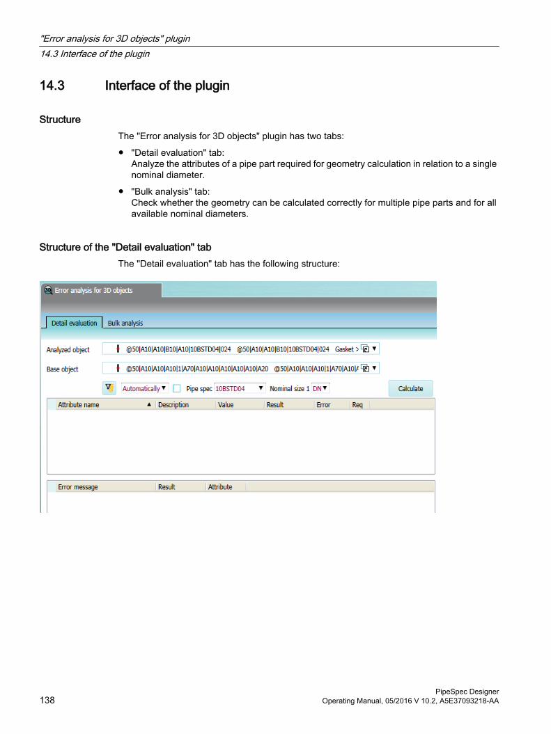
14.3 Interface of the plugin
StructureThe "Error analysis for 3D objects" plugin has two tabs:
● "Detail evaluation" tab:Analyze the attributes of a pipe part required for geometry calculation in relation to a single nominal diameter.
● "Bulk analysis" tab:Check whether the geometry can be calculated correctly for multiple pipe parts and for all available nominal diameters.
Structure of the "Detail evaluation" tabThe "Detail evaluation" tab has the following structure:
"Error analysis for 3D objects" plugin14.3 Interface of the plugin
PipeSpec Designer138 Operating Manual, 05/2016 V 10.2, A5E37093218-AA
● "Analyzed object" list:
– Link to the base object of the pipe part whose geometry calculation you are checking.
– Even if you drag the base object of a pipe spec element to the list, the corresponding base object from the pipe part catalog is still evaluated.
– You can see all base objects which you have dragged into the list. To do so, open the list.
● "Base object" list:The list is for information purposes only.It is displayed if you have dragged an engineering object or a pipe spec element into the "Analyzed object" list. It shows the corresponding base object from the pipe part catalog.
● "Calculate" button:Starts the calculation of the pipe part properties.
● Tool bar:In the toolbar, set the values necessary to calculate the geometry.The toolbar contains the following control elements:
– "Activate nominal diameter filter" button:
The filter is only applied if you have dragged the base object of a pipe spec element into the "Analyzed object" list.Disabled: You see the nominal diameter range set for the pipe spec in the field for the nominal diameter in the toolbar.Active: The base object comes from the base object of the pipe part from which the pipe spec element is derived, from the "Display for nominal diameter range" tab.
– All attributes referenced in the "Y00T00011.Y00A02625 VSUI attributes" attribute of the pipe part, for example, the attributes for the pipe spec and the nominal diameter
"Error analysis for 3D objects" plugin14.3 Interface of the plugin
PipeSpec DesignerOperating Manual, 05/2016 V 10.2, A5E37093218-AA 139
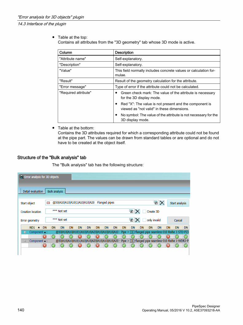
● Table at the top:Contains all attributes from the "3D geometry" tab whose 3D mode is active.
Column Description"Attribute name" Self-explanatory."Description" Self-explanatory."Value" This field normally includes concrete values or calculation for‐
mulae."Result" Result of the geometry calculation for the attribute."Error message" Type of error if the attribute could not be calculated."Required attribute" ● Green check mark: The value of the attribute is necessary
for the 3D display mode.● Red "X": The value is not present and the component is
viewed as "not valid" in these dimensions.● No symbol: The value of the attribute is not necessary for the
3D display mode.
● Table at the bottom:Contains the 3D attributes required for which a corresponding attribute could not be found at the pipe part. The values can be drawn from standard tables or are optional and do not have to be created at the object itself.
Structure of the "Bulk analysis" tabThe "Bulk analysis" tab has the following structure:
"Error analysis for 3D objects" plugin14.3 Interface of the plugin
PipeSpec Designer140 Operating Manual, 05/2016 V 10.2, A5E37093218-AA
● Field "Start object":A link to one of the following base objects:
– Pipe part from the pipe part catalog
– Structure object from the pipe part catalog
– Pipe spec element
– Pipe spec
If there are no base objects underneath the start object, the start object is analyzed. If there are more base objects underneath the start object, they are analyzed recursively.
● "Unit location" field:
– Link to an engineering object of the "Device" system type whose creation mode is "Free" and which has the "Coordinate system definition" tab
– Optional
– Requirement: "Create 3D" option is activated
– The 3D objects generated are created underneath the object linked here.
● "Error geometry" field:
– Link to a 3D base object
– Optional
– Requirement: The "Create 3D" option is activated and the "Unit location" reference is set.
– For objects whose geometry could not be calculated or could not be calculated correctly, 3D objects are generated with the base object linked here.
● "Create 3D" option:
– Optional
– Requirement: "Unit location" reference is set
– Active: 3D objects are created for all objects, even objects whose geometry was not calculated correctly. The 3D objects can be displayed in the Viper 3D Editor.
● "Invalid only" option:
– Optional
– Requirement: "Create 3D" option is activated
– Active: 3D objects are only created for the objects whose geometry could not be calculated correctly.
● "Start analysis" button:Starts the analysis. Data is written to the results table even while the analysis is still in progress.
● "Cancel" button:Cancels the analysis.
"Error analysis for 3D objects" plugin14.3 Interface of the plugin
PipeSpec DesignerOperating Manual, 05/2016 V 10.2, A5E37093218-AA 141
● Results table:
– The table analyzes whether the geometry can be calculated:Green check mark: Geometry calculated correctlyRed "X": Geometry not calculated correctly
– If the start object is a pipe spec or the base object of a pipe spec element: The geometry is checked for the nominal diameter range specified by the pipe spec.
– If the start object comes from the pipe part catalog: The geometry for the nominal diameter range specified by the pipe part on the "Display for nominal diameter range" tab is checked.
● Area underneath the table:Displays a progress bar and outputs the status of the analysis.
14.4 Checking the pipe part geometry
14.4.1 Checking the pipe part geometry for errors
ProcedureTo check whether the geometry attributes of a pipe part have been calculated correctly for a given nominal diameter, proceed as follows:
1. Open the "Error analysis for 3D objects" plugin. The "Detail evaluation" tab is active.
2. Drag&drop an object into the "Analyzed object" field. You have the following options:
– 3D engineering object
– Base object from the pipe part catalog
– Base object of a pipe part within a pipe spec
3. Set values for the geometry calculation via the plugin's toolbar.
4. Start the calculation.
5. Use the results to identify the error sources.
"Error analysis for 3D objects" plugin14.4 Checking the pipe part geometry
PipeSpec Designer142 Operating Manual, 05/2016 V 10.2, A5E37093218-AA
6. For attributes which have not been calculated at all or have been calculated incorrectly:
– Correct the value entered in the "Value" column.
– If required: Correct the values for the geometry calculation in the plugin's toolbar.
– Check your entries by restarting the calculation.
Repeat these steps until the geometry is calculated correctly.
7. Save your entries.
Note
Changes should be made at the base object from the pipe part catalog because COMOS usually references the pipe part catalog.
Changes to the attributes of a pipe part should be made at the base object from the pipe part catalog.
See alsoCalling a plugin (Page 137)
Displaying 3D attributes of a pipe part (Page 143)
Calculating the geometry of a pipe part (Page 144)
14.4.2 Displaying 3D attributes of a pipe part
Procedure1. Select a base object from the pipe part catalog on the "Base objects" tab in the Navigator.
2. Drag&drop the base object to the "Base object" field on the "Detail evaluation" tab.
Result● The attributes of the pipe part are read in and output in the table underneath the base object:
– All attributes on the "3D geometry" tab for which the following applies are read in: Properties of the attribute, "Link" tab, "3D" control group, "Mode" list: Value "On"
– The "Attribute name", "Description", and "Value" table columns are read in.
● A toolbar appears above the table. Use the toolbar to set the attribute values necessary to calculate the geometry of the pipe part.
Base object of a PipeSpec elementIt is advisable to analyze the pipe spec elements if the attributes used to calculate the geometry get their values via the "CatPC" formula. They are then calculated on the basis of the pipe spec.
"Error analysis for 3D objects" plugin14.4 Checking the pipe part geometry
PipeSpec DesignerOperating Manual, 05/2016 V 10.2, A5E37093218-AA 143
When you drag a pipe spec element into the "Base object" field, it is the base object from the pipe part catalog from which the pipe spec element is derived that is displayed in the "Base object" field. The base object of the pipe spec element is displayed grayed out underneath:
The results table evaluates the base object from the pipe part catalog. Only the pipe spec is read out from the pipe spec element.
See alsoUsing the "CatPC(...)" function (Page 39)
Interface of the plugin (Page 138)
Calculating the geometry of a pipe part (Page 144)
14.4.3 Calculating the geometry of a pipe part
Procedure1. In the tab toolbar, set the values necessary to calculate the geometry, e.g. the nominal
diameter in the "DN1" list.
2. Click the "Calculate" button.
ResultThe following table columns are filled:
● "Result" column:Contains the result of the geometry calculation. The result may materialize as follows:
– Application of the attribute value.
– Result from the formula that stands in the attribute value.
– Value from a catalog with standard values if the attribute is not set.If the value "<error>" is displayed here, then an error occurred during calculation. The error is further explained in the column "Error message".
● "Error message" column:Type of error that occurred during the calculation.
See alsoInterface of the plugin (Page 138)
Displaying 3D attributes of a pipe part (Page 143)
"Error analysis for 3D objects" plugin14.4 Checking the pipe part geometry
PipeSpec Designer144 Operating Manual, 05/2016 V 10.2, A5E37093218-AA
14.5 Nominal-diameter-dependent check of the geometry
14.5.1 Workflow
ProcedureTo check for one or more pipe parts the nominal diameters in which the geometry of the objects is calculated correctly, proceed as follows:
1. Open the plugin "Error analysis 3D objects" and change to the "Bulk analysis" tab.
2. Click on the "Base objects" tab in the Navigator and select the base object you wish to analyze.The following base objects are permitted:
– A pipe part from the pipe part catalog
– A structure object from the pipe part catalogExample: The structure object underneath which the welded pipes are located
– A pipe spec element
– A pipe spec
3. Drag&drop the base object to the "Start object" field.
4. Optional: To view the geometry in the 3D view following the analysis, make the following settings:
– In the Navigator, click on the "Units" tab and select the object underneath which the 3D objects are to be created.Requirement: The object has the "Coordinate system definition" tab.
– Drag&drop the object to the "Unit location" field.
– Activate the "Create 3D" option.
5. Optional: Define which base object is used for pipe parts whose geometry is not calculated correctly.
– Requirement: The "Create 3D" option is activated and the "Unit location" reference is set.
– Click on the "Base object" tab in the Navigator and select the base object to be used as the template.
– Drag&drop the object to the "Error geometry" field.
6. Optional: If you only want 3D objects to be created for pipe parts whose geometry is not calculated correctly, activate the "Invalid only" option.
7. Click the "Start analysis" button.
"Error analysis for 3D objects" plugin14.5 Nominal-diameter-dependent check of the geometry
PipeSpec DesignerOperating Manual, 05/2016 V 10.2, A5E37093218-AA 145
Result● If the start object is a pipe spec element or a pipe part from the pipe part catalog, the start
object is analyzed.
● If the start object is a pipe spec or a structure object from the pipe part catalog, the subordinate objects are analyzed recursively. The time taken to complete the analysis depends upon the number of objects.
● If the start object is the base object of a pipe spec element, the geometry is checked for the nominal diameter range specified by the pipe spec.
● If the start object comes from the pipe part catalog, the geometry for the nominal diameter range specified by the pipe part on the "Display for nominal diameter range" tab is checked.
● For each pipe part, a status is determined for each nominal diameter:
– Green check mark: The geometry of the pipe part has been calculated correctly.
– Red cross: The geometry of the pipe part has not been calculated correctly.
14.5.2 Canceling or continuing the analysisDependent upon how many objects are analyzed, the analysis may take some time.
Canceling the analysisTo terminate the analysis prematurely, click on the "Cancel" button.
Resuming the analysisClick the "Resume" button to resume the analysis.
14.5.3 Viewing the result of the analysis in the 3D Editor
Requirement● A bulk analysis has been carried out
● During the bulk analysis, the "Create 3D" option was activated and the "Unit location" field was set.
Procedure1. In the Navigator, select the object entered in the plugin in the "Unit location" field on the
"Bulk analysis" tab.
2. Select "Extra > 3D review > 3D view" from the menu.
"Error analysis for 3D objects" plugin14.5 Nominal-diameter-dependent check of the geometry
PipeSpec Designer146 Operating Manual, 05/2016 V 10.2, A5E37093218-AA
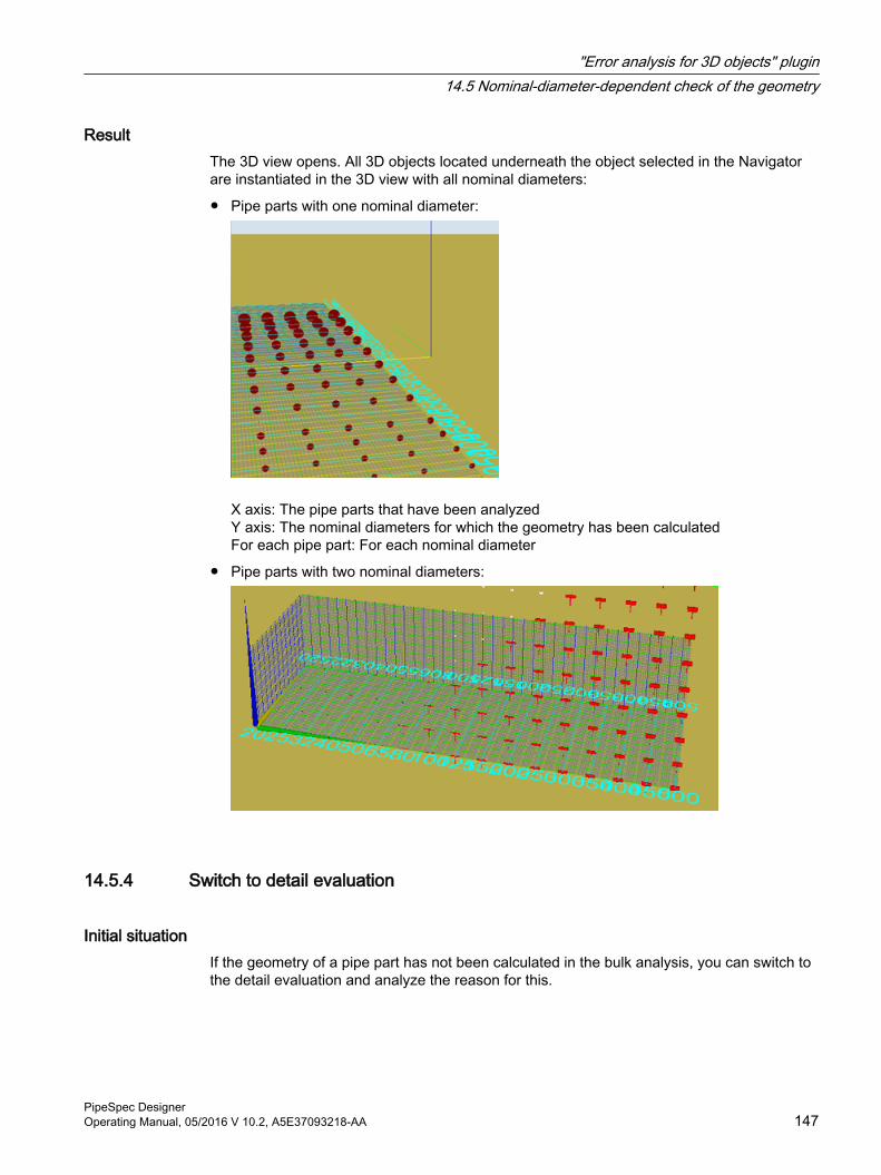
ResultThe 3D view opens. All 3D objects located underneath the object selected in the Navigator are instantiated in the 3D view with all nominal diameters:
● Pipe parts with one nominal diameter:
X axis: The pipe parts that have been analyzedY axis: The nominal diameters for which the geometry has been calculatedFor each pipe part: For each nominal diameter
● Pipe parts with two nominal diameters:
14.5.4 Switch to detail evaluation
Initial situationIf the geometry of a pipe part has not been calculated in the bulk analysis, you can switch to the detail evaluation and analyze the reason for this.
"Error analysis for 3D objects" plugin14.5 Nominal-diameter-dependent check of the geometry
PipeSpec DesignerOperating Manual, 05/2016 V 10.2, A5E37093218-AA 147
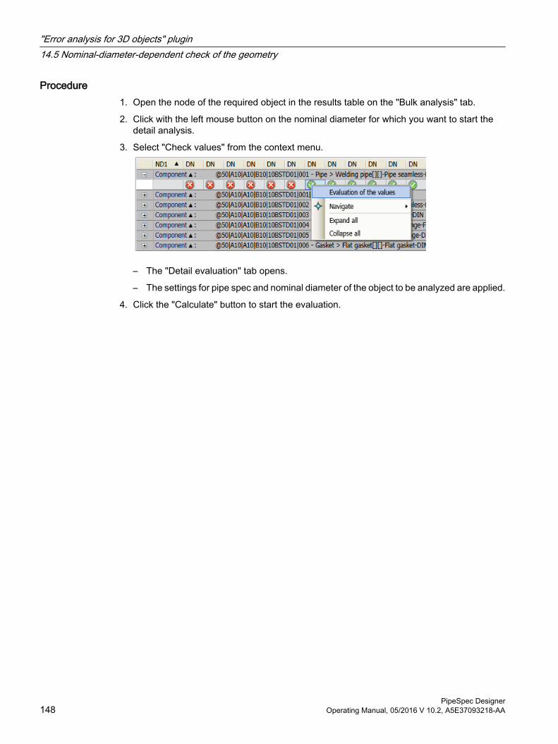
Procedure1. Open the node of the required object in the results table on the "Bulk analysis" tab.
2. Click with the left mouse button on the nominal diameter for which you want to start the detail analysis.
3. Select "Check values" from the context menu.
– The "Detail evaluation" tab opens.
– The settings for pipe spec and nominal diameter of the object to be analyzed are applied.
4. Click the "Calculate" button to start the evaluation.
"Error analysis for 3D objects" plugin14.5 Nominal-diameter-dependent check of the geometry
PipeSpec Designer148 Operating Manual, 05/2016 V 10.2, A5E37093218-AA
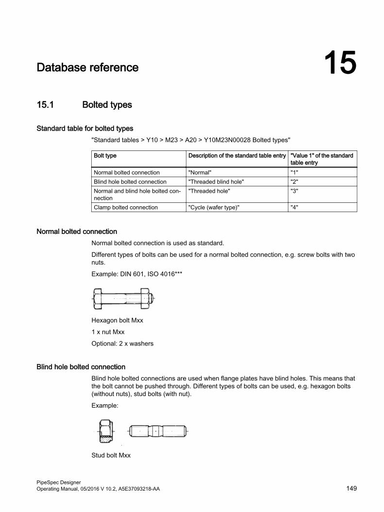
Database reference 1515.1 Bolted types
Standard table for bolted types"Standard tables > Y10 > M23 > A20 > Y10M23N00028 Bolted types"
Bolt type Description of the standard table entry "Value 1" of the standard table entry
Normal bolted connection "Normal" "1"Blind hole bolted connection "Threaded blind hole" "2"Normal and blind hole bolted con‐nection
"Threaded hole" "3"
Clamp bolted connection "Cycle (wafer type)" "4"
Normal bolted connectionNormal bolted connection is used as standard.
Different types of bolts can be used for a normal bolted connection, e.g. screw bolts with two nuts.
Example: DIN 601, ISO 4016***
Hexagon bolt Mxx
1 x nut Mxx
Optional: 2 x washers
Blind hole bolted connectionBlind hole bolted connections are used when flange plates have blind holes. This means that the bolt cannot be pushed through. Different types of bolts can be used, e.g. hexagon bolts (without nuts), stud bolts (with nut).
Example:
Stud bolt Mxx
PipeSpec DesignerOperating Manual, 05/2016 V 10.2, A5E37093218-AA 149
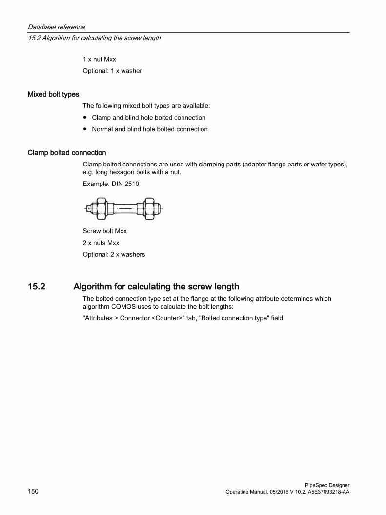
1 x nut Mxx
Optional: 1 x washer
Mixed bolt typesThe following mixed bolt types are available:
● Clamp and blind hole bolted connection
● Normal and blind hole bolted connection
Clamp bolted connectionClamp bolted connections are used with clamping parts (adapter flange parts or wafer types), e.g. long hexagon bolts with a nut.
Example: DIN 2510
Screw bolt Mxx
2 x nuts Mxx
Optional: 2 x washers
15.2 Algorithm for calculating the screw lengthThe bolted connection type set at the flange at the following attribute determines which algorithm COMOS uses to calculate the bolt lengths:
"Attributes > Connector <Counter>" tab, "Bolted connection type" field
Database reference15.2 Algorithm for calculating the screw length
PipeSpec Designer150 Operating Manual, 05/2016 V 10.2, A5E37093218-AA
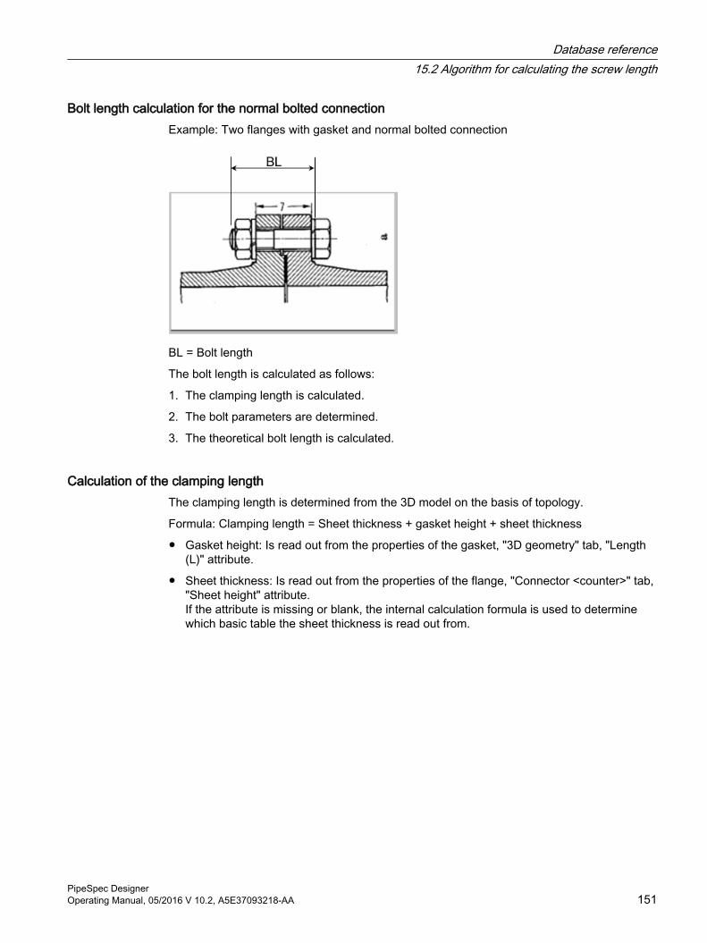
Bolt length calculation for the normal bolted connectionExample: Two flanges with gasket and normal bolted connection
BL = Bolt length
The bolt length is calculated as follows:
1. The clamping length is calculated.
2. The bolt parameters are determined.
3. The theoretical bolt length is calculated.
Calculation of the clamping lengthThe clamping length is determined from the 3D model on the basis of topology.
Formula: Clamping length = Sheet thickness + gasket height + sheet thickness
● Gasket height: Is read out from the properties of the gasket, "3D geometry" tab, "Length (L)" attribute.
● Sheet thickness: Is read out from the properties of the flange, "Connector <counter>" tab, "Sheet height" attribute.If the attribute is missing or blank, the internal calculation formula is used to determine which basic table the sheet thickness is read out from.
Database reference15.2 Algorithm for calculating the screw length
PipeSpec DesignerOperating Manual, 05/2016 V 10.2, A5E37093218-AA 151
Determining the bolt parameters● The following bolt parameters are taken from the "Dimensions" tab of the geometry table
for flanges.
– Hole circle
– Outer diameter flange
– Number of bolts
– Dimension for bolts and nuts
COMOS determines which geometry table is used during runtime by evaluating parameters, such as the connection type and pressure stage of the flange.
● Nut height and overlap are determined as follows:
– COMOS reads out the nominal diameter of the flange.
– COMOS reads the suitable dimension from the "DIM" column of the geometry table for the bolt parameters.
– COMOS then refers to the geometry table for nuts to determine which nut height and which overlap have been specified for this dimension.
● The height of the washers is determined as follows:Same as nuts. COMOS takes the height of the washers from the geometry table for washers.
Calculation of the theoretical bolt lengthFormula: Bolt length = Hole circle + 2* height of the washer + nut height + overlap
COMOS searches the geometry table for bolts for the dimension specified by the geometry table for flanges in order to find the value equal to the calculated bolt length, or failing that the next highest value.
This value is the calculated bolt length.
See alsoBasics of bolted connections (Page 109)
Using bolt sets in pipe specs (Page 120)
15.3 Example report for pipe spec documentationThe database contains a preconfigured example report for pipe spec documentation.
The report is created under the base object for pipe specs:
"@20 > C90 > A10 > A20 > A20.DA.001 Pipe spec documentation"
15.4 Example report for pipe part documentationThe database contains a preconfigured example report documenting the pipe spec elements.
Database reference15.4 Example report for pipe part documentation
PipeSpec Designer152 Operating Manual, 05/2016 V 10.2, A5E37093218-AA
The report was created at the following node from where it is inherited to all base objects of the pipe spec elements:
"@10 > A20 > A20 > A10 > A10 DA 001 Component documentation"
15.5 Pipe parts in the pipe part catalog
15.5.1 Tabs and attributesAdministering pipe part catalogs (Page 27) contains an overview of the tabs and attributes of the pipe parts from the pipe part catalog and how they are configured.
15.5.2 Change DisplayValue()
RequirementAn attribute of the pipe part has been saved with a standard table.
PrincipleWhen you click on the button next to the attribute to view the list of possible values, you see the description of the standard table entries.
To display a different description for a standard table entry, change the DisplayValue.
Use the text from "Value 3" of the standard tables. Use the implementation of the "GetDisplayValue()" script block described below for this purpose.
When you expand the list you continue to see the description.
Implementation of the "GetDisplayValue()" script blockProperties of the attribute, "Scripts" tab, "GetDisplayValue()" script block: Apply database implementation.
Example attribute with this implementation:
"Y00A04970 Type of fastening"
Database reference15.5 Pipe parts in the pipe part catalog
PipeSpec DesignerOperating Manual, 05/2016 V 10.2, A5E37093218-AA 153
15.5.3 Navigator description from pipe part attributes
Principle"Text blocks" tab, "Representation of the device-describing text at object" control group, "Description" attribute: The values of the attributes entered in the "TValue" calculation formula can be compiled to form an overall string describing the pipe part.
If the pipe part and the attributes used in the calculation formula implement the scripts described below, this string is automatically set as the description of the pipe part An existing description is overwritten and the new description is shown in the navigator.
Attributes scriptIf the value of one of the attributes evaluated in the "TValue" calculation formula changes, this change should be taken into account immediately. For this to happen, the attributes must implement the "OnChange" script block as in the database.
Example attribute with this implementation:
"Y00T00011.Y00A00009 GeoType"
See also"Text blocks" tab (Page 48)
"Part description" tab (Page 44)
15.5.4 Inheritance of the nominal diameters and pipe spec
Application areaInteraction between P&ID, pipe part catalog and 3D.
IntroductionThe component dimensions are parameterized with the following properties:
● Nominal diameter
● Nominal pressure
● Connection type
● Contact face
Database reference15.5 Pipe parts in the pipe part catalog
PipeSpec Designer154 Operating Manual, 05/2016 V 10.2, A5E37093218-AA
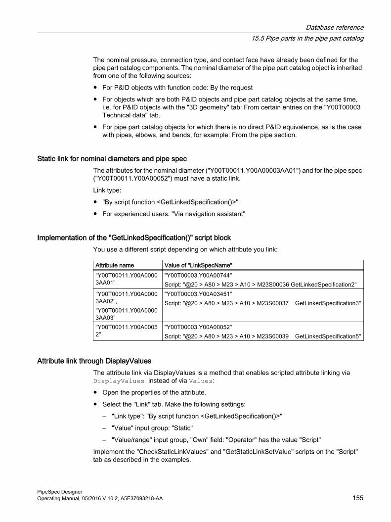
The nominal pressure, connection type, and contact face have already been defined for the pipe part catalog components. The nominal diameter of the pipe part catalog object is inherited from one of the following sources:
● For P&ID objects with function code: By the request
● For objects which are both P&ID objects and pipe part catalog objects at the same time, i.e. for P&ID objects with the "3D geometry" tab: From certain entries on the "Y00T00003 Technical data" tab.
● For pipe part catalog objects for which there is no direct P&ID equivalence, as is the case with pipes, elbows, and bends, for example: From the pipe section.
Static link for nominal diameters and pipe specThe attributes for the nominal diameter ("Y00T00011.Y00A00003AA01") and for the pipe spec ("Y00T00011.Y00A00052") must have a static link.
Link type:
● "By script function <GetLinkedSpecification()>"
● For experienced users: "Via navigation assistant"
Implementation of the "GetLinkedSpecification()" script blockYou use a different script depending on which attribute you link:
Attribute name Value of "LinkSpecName""Y00T00011.Y00A00003AA01"
"Y00T00003.Y00A00744"Script: "@20 > A80 > M23 > A10 > M23S00036 GetLinkedSpecification2"
"Y00T00011.Y00A00003AA02","Y00T00011.Y00A00003AA03"
"Y00T00003.Y00A03451"Script: "@20 > A80 > M23 > A10 > M23S00037 GetLinkedSpecification3"
"Y00T00011.Y00A00052"
"Y00T00003.Y00A00052"Script: "@20 > A80 > M23 > A10 > M23S00039 GetLinkedSpecification5"
Attribute link through DisplayValuesThe attribute link via DisplayValues is a method that enables scripted attribute linking via DisplayValues instead of via Values:
● Open the properties of the attribute.
● Select the "Link" tab. Make the following settings:
– "Link type": "By script function <GetLinkedSpecification()>"
– "Value" input group: "Static"
– "Value/range" input group, "Own" field: "Operator" has the value "Script"
Implement the "CheckStaticLinkValues" and "GetStaticLinkSetValue" scripts on the "Script" tab as described in the examples.
Database reference15.5 Pipe parts in the pipe part catalog
PipeSpec DesignerOperating Manual, 05/2016 V 10.2, A5E37093218-AA 155
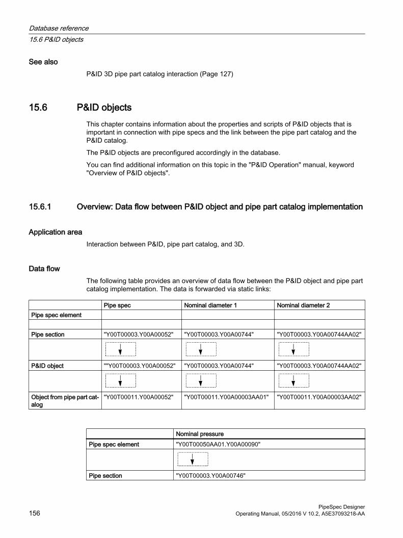
See alsoP&ID 3D pipe part catalog interaction (Page 127)
15.6 P&ID objectsThis chapter contains information about the properties and scripts of P&ID objects that is important in connection with pipe specs and the link between the pipe part catalog and the P&ID catalog.
The P&ID objects are preconfigured accordingly in the database.
You can find additional information on this topic in the "P&ID Operation" manual, keyword "Overview of P&ID objects".
15.6.1 Overview: Data flow between P&ID object and pipe part catalog implementation
Application areaInteraction between P&ID, pipe part catalog, and 3D.
Data flowThe following table provides an overview of data flow between the P&ID object and pipe part catalog implementation. The data is forwarded via static links:
Pipe spec Nominal diameter 1 Nominal diameter 2 Pipe spec element Pipe section "Y00T00003.Y00A00052" "Y00T00003.Y00A00744" "Y00T00003.Y00A00744AA02"
P&ID object ""Y00T00003.Y00A00052" "Y00T00003.Y00A00744" "Y00T00003.Y00A00744AA02"
Object from pipe part cat‐alog
"Y00T00011.Y00A00052" "Y00T00011.Y00A00003AA01" "Y00T00011.Y00A00003AA02"
Nominal pressurePipe spec element "Y00T00050AA01.Y00A00090"
Pipe section "Y00T00003.Y00A00746"
Database reference15.6 P&ID objects
PipeSpec Designer156 Operating Manual, 05/2016 V 10.2, A5E37093218-AA
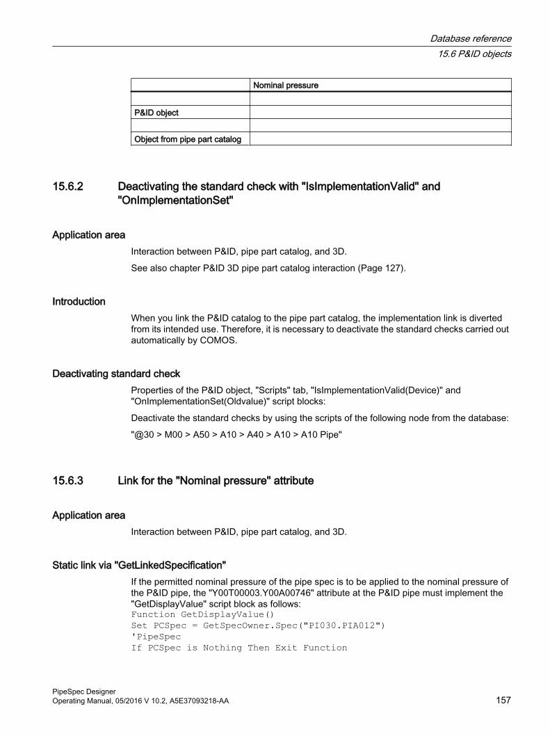
Nominal pressure P&ID object Object from pipe part catalog
15.6.2 Deactivating the standard check with "IsImplementationValid" and "OnImplementationSet"
Application areaInteraction between P&ID, pipe part catalog, and 3D.
See also chapter P&ID 3D pipe part catalog interaction (Page 127).
IntroductionWhen you link the P&ID catalog to the pipe part catalog, the implementation link is diverted from its intended use. Therefore, it is necessary to deactivate the standard checks carried out automatically by COMOS.
Deactivating standard checkProperties of the P&ID object, "Scripts" tab, "IsImplementationValid(Device)" and "OnImplementationSet(Oldvalue)" script blocks:
Deactivate the standard checks by using the scripts of the following node from the database:
"@30 > M00 > A50 > A10 > A40 > A10 > A10 Pipe"
15.6.3 Link for the "Nominal pressure" attribute
Application areaInteraction between P&ID, pipe part catalog, and 3D.
Static link via "GetLinkedSpecification"If the permitted nominal pressure of the pipe spec is to be applied to the nominal pressure of the P&ID pipe, the "Y00T00003.Y00A00746" attribute at the P&ID pipe must implement the "GetDisplayValue" script block as follows:Function GetDisplayValue()Set PCSpec = GetSpecOwner.Spec("PI030.PIA012") 'PipeSpecIf PCSpec is Nothing Then Exit Function
Database reference15.6 P&ID objects
PipeSpec DesignerOperating Manual, 05/2016 V 10.2, A5E37093218-AA 157
If PCSpec.Value = ""Then Exit FunctionPCName = PCSpec.ValueSet PipeClass = lib.StdValues3D(Project).pcGetPipeClass(PCName)If PipeClass is nothing Then Exit FunctionSet CDev = PipeClass.CdeviceSet Sp = CDev.Spec("C2.V2.P")'C2.V2.P: List specification'P: Calls column P, in in which the second value ("Row") is fetched using GetXValue(1).If not SP is Nothing then GetDisplayValue = SP.GetXValue(1) End Function
See alsoWorkflow (Page 133)
Database reference15.6 P&ID objects
PipeSpec Designer158 Operating Manual, 05/2016 V 10.2, A5E37093218-AA
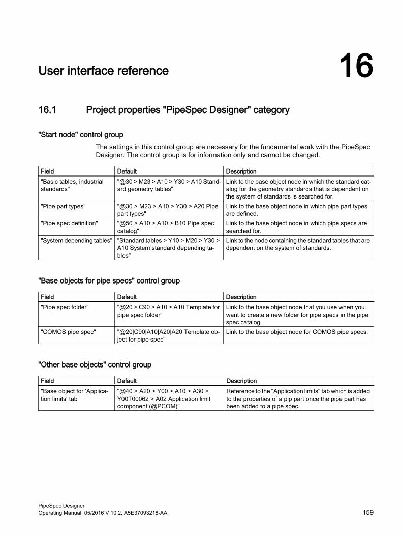
User interface reference 1616.1 Project properties "PipeSpec Designer" category
"Start node" control groupThe settings in this control group are necessary for the fundamental work with the PipeSpec Designer. The control group is for information only and cannot be changed.
Field Default Description"Basic tables, industrial standards"
"@30 > M23 > A10 > Y30 > A10 Stand‐ard geometry tables"
Link to the base object node in which the standard cat‐alog for the geometry standards that is dependent on the system of standards is searched for.
"Pipe part types" "@30 > M23 > A10 > Y30 > A20 Pipe part types"
Link to the base object node in which pipe part types are defined.
"Pipe spec definition" "@50 > A10 > A10 > B10 Pipe spec catalog"
Link to the base object node in which pipe specs are searched for.
"System depending tables" "Standard tables > Y10 > M20 > Y30 > A10 System standard depending ta‐bles"
Link to the node containing the standard tables that are dependent on the system of standards.
"Base objects for pipe specs" control group
Field Default Description"Pipe spec folder" "@20 > C90 > A10 > A10 Template for
pipe spec folder"Link to the base object node that you use when you want to create a new folder for pipe specs in the pipe spec catalog.
"COMOS pipe spec" "@20|C90|A10|A20|A20 Template ob‐ject for pipe spec"
Link to the base object node for COMOS pipe specs.
"Other base objects" control group
Field Default Description"Base object for 'Applica‐tion limits' tab"
"@40 > A20 > Y00 > A10 > A30 > Y00T00062 > A02 Application limit component (@PCOM)"
Reference to the "Application limits" tab which is added to the properties of a pip part once the pipe part has been added to a pipe spec.
PipeSpec DesignerOperating Manual, 05/2016 V 10.2, A5E37093218-AA 159
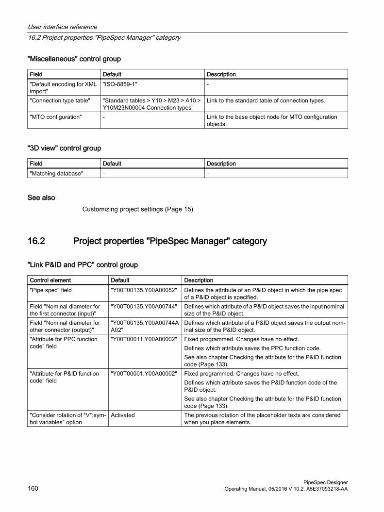
"Miscellaneous" control group
Field Default Description"Default encoding for XML import"
"ISO-8859-1" -
"Connection type table" "Standard tables > Y10 > M23 > A10 > Y10M23N00004 Connection types"
Link to the standard table of connection types.
"MTO configuration" - Link to the base object node for MTO configuration objects.
"3D view" control group
Field Default Description"Matching database" - -
See alsoCustomizing project settings (Page 15)
16.2 Project properties "PipeSpec Manager" category
"Link P&ID and PPC" control group
Control element Default Description"Pipe spec" field "Y00T00135.Y00A00052" Defines the attribute of an P&ID object in which the pipe spec
of a P&ID object is specified.Field "Nominal diameter for the first connector (input)"
"Y00T00135.Y00A00744" Defines which attribute of a P&ID object saves the input nominal size of the P&ID object.
Field "Nominal diameter for other connector (output)"
"Y00T00135.Y00A00744AA02"
Defines which attribute of a P&ID object saves the output nom‐inal size of the P&ID object.
"Attribute for PPC function code" field
"Y00T00011.Y00A00002" Fixed programmed. Changes have no effect.Defines which attribute saves the PPC function code.See also chapter Checking the attribute for the P&ID function code (Page 133).
"Attribute for P&ID function code" field
"Y00T00001.Y00A00002" Fixed programmed. Changes have no effect.Defines which attribute saves the P&ID function code of the P&ID object.See also chapter Checking the attribute for the P&ID function code (Page 133).
"Consider rotation of *V*:sym‐bol variables" option
Activated The previous rotation of the placeholder texts are considered when you place elements.
User interface reference16.2 Project properties "PipeSpec Manager" category
PipeSpec Designer160 Operating Manual, 05/2016 V 10.2, A5E37093218-AA