Embed Size (px)
Citation preview
COMPANION 1000COMPANION T
L I Q U I D OX Y G E N P O RTA B L E S
Puritan-Bennett 5647 Dividend DriveIndianapolis, IN 46241 USA Customer Service:1-800-635-5267, press 2Technical Support:1-800-255-6774, press 2
TECHNICAL MANUAL
Part Number B-701964-00 Rev. A


Companion 1000/T Liquid Oxygen System Technical Manual
i B-701964-00 Rev. A
Companion 1000/T Liquid Oxygen System Technical Manual
ii B-701964-00 Rev. A
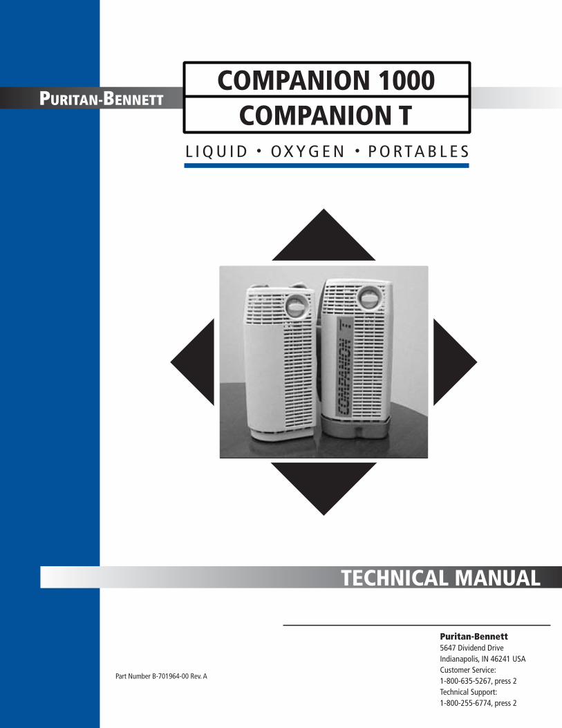
LIST OF EFFECTIVE PAGES
This list of effective pages represents manual P/N B-701964-00, Revision A.
REVISION DESCRIPTION DATE
A Initial Release 02/01
EFFECTIVE PAGES REVISION
All A
B-701964-00 Rev. A iii
Companion 1000/T Liquid Oxygen System Technical Manual
DEFINITION OF STATEMENTS
Statements in this manual preceded by the following words are of special significance:
INTELLECTUAL PROPERTY NOTICES
Companion® is a trademark of PURITAN-BENNETT.
SNOOP® is a trademark of the SWAGELOK Co.
Teflon® and Krytox® are trademarks of E.I. DUPONT DE NEMOURS & Co.
Kel-F® and Scotch-Brite™ are trademarks of the 3M Co.
WARNING
A warning describes conditions that concern your personal safety and the safety of others. It includes the actions required to prevent injury. Ignoring warnings can lead to injury or death.
CAUTION:A caution informs you about conditions that may cause possible damage to the equipment or other property, or situations that may cause reduced or no oxygen flow.
NOTE: Notes provide important information about using the equipment properly.
NOTE: SI pressure values expressed in this manual are referenced to atmosphere.
Companion 1000/T Liquid Oxygen System Technical Manual
iv B-701964-00 Rev. A
PREFACE
This manual provides the information needed to service both the Puritan Bennett Companion 1000 and the Puritan Bennett Companion T Portable liquid oxygen units. This information is intended for use by technicians or personnel qualified to repair and service medical liquid oxygen equipment. Do not attempt to fill or repair these units until you read and understand the information in this manual.
The following document contains additional information useful in servicing this equipment:
Companion Liquid Oxygen Systems Operating Instructions: P/N B-701417-00
For product assistance contact: Puritan-Bennett5647 Dividend DriveIndianapolis, IN 46241Customer Service:1-800-635-5267, press 2Technical Support:1-800-255-6774, press 2
Information contained in this document, including performance specifications, is subject to change without notice. Puritan-Bennett makes no warranty of any kind with regard to the material in this manual, including, but not limited to, the implied warranties of salability and fitness for a particular purpose. Puritan-Bennett shall not be liable for errors contained herein or for incidental or consequential damages in connection with either providing this manual or the use of material in this manual. Companion is a trademark of Puritan-Bennett. The information contained in this manual is the sole property of Puritan-Bennett and may not be reproduced without the permission of the company. Copyright© 2001 by Puritan-Bennett. All rights reserved.
NOTE: Companion 1000 and Companion T Portable units are intended only for the delivery of medical grade oxygen as prescribed by a physician.
WARNING
Improper usage hazard. Oxygen supplied from this equipment is for supplemental use and is not intended to be life supporting or life sustaining. This equipment is not intended for use by patients who would suffer immediate, permanent, or serious health consequences as a result of an interruption in their oxygen supply.
B-701964-00 Rev. A v
TABLE OF CONTENTS
SECTION 1: INTRODUCTION. . . . . . . . . . . . . . . . . . . . . . . . . . . . . . . . . . . . . . . . . . . . . . . . . . . . . 1-11.1 Product Description. . . . . . . . . . . . . . . . . . . . . . . . . . . . . . . . . . . . . . . . . . . . . . . . . . . . . 1-2
1.2 Serial Number Identification . . . . . . . . . . . . . . . . . . . . . . . . . . . . . . . . . . . . . . . . . . . . . . 1-2
1.3 Safety Precautions . . . . . . . . . . . . . . . . . . . . . . . . . . . . . . . . . . . . . . . . . . . . . . . . . . . . . . 1-31.3.1 Cold Safety . . . . . . . . . . . . . . . . . . . . . . . . . . . . . . . . . . . . . . . . . . . . . . . . . . . . . . . . . . 1-31.3.2 Expansion Safety. . . . . . . . . . . . . . . . . . . . . . . . . . . . . . . . . . . . . . . . . . . . . . . . . . . . . . 1-41.3.3 Fire Safety . . . . . . . . . . . . . . . . . . . . . . . . . . . . . . . . . . . . . . . . . . . . . . . . . . . . . . . . . . . 1-4
1.4 Companion 1000/T Specifications . . . . . . . . . . . . . . . . . . . . . . . . . . . . . . . . . . . . . . . . . . 1-61.4.1 Table 1-1: Performance Specifications. . . . . . . . . . . . . . . . . . . . . . . . . . . . . . . . . . . . . . 1-61.4.2 Table 1-2: Run Time Specifications. . . . . . . . . . . . . . . . . . . . . . . . . . . . . . . . . . . . . . . . 1-7
1.5 Unpacking, Installation, and Repacking . . . . . . . . . . . . . . . . . . . . . . . . . . . . . . . . . . . . . 1-71.5.1 Unpacking. . . . . . . . . . . . . . . . . . . . . . . . . . . . . . . . . . . . . . . . . . . . . . . . . . . . . . . . . . . 1-71.5.2 Installation . . . . . . . . . . . . . . . . . . . . . . . . . . . . . . . . . . . . . . . . . . . . . . . . . . . . . . . . . . 1-71.5.3 Repackaging for Return . . . . . . . . . . . . . . . . . . . . . . . . . . . . . . . . . . . . . . . . . . . . . . . . 1-8
1.6 Controls, Indicators, and Connectors . . . . . . . . . . . . . . . . . . . . . . . . . . . . . . . . . . . . . . . 1-81.6.1 Fill Connector . . . . . . . . . . . . . . . . . . . . . . . . . . . . . . . . . . . . . . . . . . . . . . . . . . . . . . . . 1-81.6.2 Vent Valve . . . . . . . . . . . . . . . . . . . . . . . . . . . . . . . . . . . . . . . . . . . . . . . . . . . . . . . . . . 1-81.6.3 Contents Indicator . . . . . . . . . . . . . . . . . . . . . . . . . . . . . . . . . . . . . . . . . . . . . . . . . . . . 1-81.6.4 Flow Control . . . . . . . . . . . . . . . . . . . . . . . . . . . . . . . . . . . . . . . . . . . . . . . . . . . . . . . . 1-91.6.5 Oxygen Outlet Connector. . . . . . . . . . . . . . . . . . . . . . . . . . . . . . . . . . . . . . . . . . . . . . . 1-91.6.6 Moisture Cup Assembly (Companion T). . . . . . . . . . . . . . . . . . . . . . . . . . . . . . . . . . . . 1-9
1.7 Filling Instructions for Technicians . . . . . . . . . . . . . . . . . . . . . . . . . . . . . . . . . . . . . . . . . 1-91.7.1 Pre-Fill Inspection . . . . . . . . . . . . . . . . . . . . . . . . . . . . . . . . . . . . . . . . . . . . . . . . . . . . 1-101.7.2 Filling Procedure . . . . . . . . . . . . . . . . . . . . . . . . . . . . . . . . . . . . . . . . . . . . . . . . . . . . . 1-101.7.3 Post-Fill Inspection . . . . . . . . . . . . . . . . . . . . . . . . . . . . . . . . . . . . . . . . . . . . . . . . . . . 1-13
1.8 Operating Procedure . . . . . . . . . . . . . . . . . . . . . . . . . . . . . . . . . . . . . . . . . . . . . . . . . . . 1-13
1.9 Maintenance . . . . . . . . . . . . . . . . . . . . . . . . . . . . . . . . . . . . . . . . . . . . . . . . . . . . . . . . . 1-14
1.10 Recommended Tools, Test Equipment, and Service Materials . . . . . . . . . . . . . . . . . . . . 1-15
1.11 Calibrating Test Equipment. . . . . . . . . . . . . . . . . . . . . . . . . . . . . . . . . . . . . . . . . . . . . . 1-16
1.12 Accessories . . . . . . . . . . . . . . . . . . . . . . . . . . . . . . . . . . . . . . . . . . . . . . . . . . . . . . . . . . 1-17
SECTION 2: THEORY OF OPERATION . . . . . . . . . . . . . . . . . . . . . . . . . . . . . . . . . . . . . . . . . . . . . 2-12.1 Companion 1000/T Component Descriptions . . . . . . . . . . . . . . . . . . . . . . . . . . . . . . . . . 2-1
2.1.1 Cryogenic Container . . . . . . . . . . . . . . . . . . . . . . . . . . . . . . . . . . . . . . . . . . . . . . . . . . . 2-12.1.2 Fill Connector . . . . . . . . . . . . . . . . . . . . . . . . . . . . . . . . . . . . . . . . . . . . . . . . . . . . . . . . 2-22.1.3 Warming Coil . . . . . . . . . . . . . . . . . . . . . . . . . . . . . . . . . . . . . . . . . . . . . . . . . . . . . . . . 2-32.1.4 Flow Control Valve. . . . . . . . . . . . . . . . . . . . . . . . . . . . . . . . . . . . . . . . . . . . . . . . . . . . 2-32.1.5 Vent Valve . . . . . . . . . . . . . . . . . . . . . . . . . . . . . . . . . . . . . . . . . . . . . . . . . . . . . . . . . . 2-42.1.6 Primary/Secondary Relief Valve . . . . . . . . . . . . . . . . . . . . . . . . . . . . . . . . . . . . . . . . . . 2-42.1.7 Contents Indicator Scale . . . . . . . . . . . . . . . . . . . . . . . . . . . . . . . . . . . . . . . . . . . . . . . . 2-5
2.2 Liquid Oxygen Saturation Principles . . . . . . . . . . . . . . . . . . . . . . . . . . . . . . . . . . . . . . . . 2-5
2.3 Companion 1000/T Operation . . . . . . . . . . . . . . . . . . . . . . . . . . . . . . . . . . . . . . . . . . . . 2-62.3.1 Filling . . . . . . . . . . . . . . . . . . . . . . . . . . . . . . . . . . . . . . . . . . . . . . . . . . . . . . . . . . . . . . 2-62.3.2 Fill Termination . . . . . . . . . . . . . . . . . . . . . . . . . . . . . . . . . . . . . . . . . . . . . . . . . . . . . . 2-72.3.3 Standby. . . . . . . . . . . . . . . . . . . . . . . . . . . . . . . . . . . . . . . . . . . . . . . . . . . . . . . . . . . . . 2-82.3.4 Oxygen Flow . . . . . . . . . . . . . . . . . . . . . . . . . . . . . . . . . . . . . . . . . . . . . . . . . . . . . . . . 2-8
Table of Contents
vi B-701964-00 Rev. A
SECTION 3: PERFORMANCE VERIFICATION. . . . . . . . . . . . . . . . . . . . . . . . . . . . . . . . . . . . . . . . 3-13.1 Equipment Required . . . . . . . . . . . . . . . . . . . . . . . . . . . . . . . . . . . . . . . . . . . . . . . . . . . . 3-1
3.2 Leakage Test . . . . . . . . . . . . . . . . . . . . . . . . . . . . . . . . . . . . . . . . . . . . . . . . . . . . . . . . . . 3-13.2.1 Liquid Leak Detector Test. . . . . . . . . . . . . . . . . . . . . . . . . . . . . . . . . . . . . . . . . . . . . . . 3-23.2.2 Pressure Hold Test . . . . . . . . . . . . . . . . . . . . . . . . . . . . . . . . . . . . . . . . . . . . . . . . . . . . 3-3
3.3 Gaseous Oxygen Tests. . . . . . . . . . . . . . . . . . . . . . . . . . . . . . . . . . . . . . . . . . . . . . . . . . . 3-43.3.1 Secondary Relief Valve Test . . . . . . . . . . . . . . . . . . . . . . . . . . . . . . . . . . . . . . . . . . . . . 3-43.3.2 Primary Relief Valve Test . . . . . . . . . . . . . . . . . . . . . . . . . . . . . . . . . . . . . . . . . . . . . . . 3-43.3.3 Vent Valve Test. . . . . . . . . . . . . . . . . . . . . . . . . . . . . . . . . . . . . . . . . . . . . . . . . . . . . . . 3-5
3.4 Liquid Oxygen Tests . . . . . . . . . . . . . . . . . . . . . . . . . . . . . . . . . . . . . . . . . . . . . . . . . . . . 3-53.4.1 Contents Indicator Test. . . . . . . . . . . . . . . . . . . . . . . . . . . . . . . . . . . . . . . . . . . . . . . . . 3-53.4.2 Flow Control Test. . . . . . . . . . . . . . . . . . . . . . . . . . . . . . . . . . . . . . . . . . . . . . . . . . . . . 3-53.4.3 Normal Evaporation Rate Test . . . . . . . . . . . . . . . . . . . . . . . . . . . . . . . . . . . . . . . . . . . 3-7
SECTION 4: TROUBLESHOOTING. . . . . . . . . . . . . . . . . . . . . . . . . . . . . . . . . . . . . . . . . . . . . . . . . 4-1
SECTION 5: SERVICE AND REPAIR . . . . . . . . . . . . . . . . . . . . . . . . . . . . . . . . . . . . . . . . . . . . . . . . 5-15.1 Pressure Fittings and Connections . . . . . . . . . . . . . . . . . . . . . . . . . . . . . . . . . . . . . . . . . . 5-1
5.1.1 Compression Fitting Makeup . . . . . . . . . . . . . . . . . . . . . . . . . . . . . . . . . . . . . . . . . . . . 5-25.1.2 Compression Fitting Remake . . . . . . . . . . . . . . . . . . . . . . . . . . . . . . . . . . . . . . . . . . . . 5-35.1.3 Compression Fitting Troubleshooting . . . . . . . . . . . . . . . . . . . . . . . . . . . . . . . . . . . . . . 5-35.1.4 Tapered Pipe Thread Make-up . . . . . . . . . . . . . . . . . . . . . . . . . . . . . . . . . . . . . . . . . . . 5-35.1.5 Tapered Pipe Thread Troubleshooting . . . . . . . . . . . . . . . . . . . . . . . . . . . . . . . . . . . . . 5-3
5.2 Side Covers . . . . . . . . . . . . . . . . . . . . . . . . . . . . . . . . . . . . . . . . . . . . . . . . . . . . . . . . . . . 5-45.2.1 Removal . . . . . . . . . . . . . . . . . . . . . . . . . . . . . . . . . . . . . . . . . . . . . . . . . . . . . . . . . . . . 5-45.2.2 Service. . . . . . . . . . . . . . . . . . . . . . . . . . . . . . . . . . . . . . . . . . . . . . . . . . . . . . . . . . . . . . 5-55.2.3 Installation . . . . . . . . . . . . . . . . . . . . . . . . . . . . . . . . . . . . . . . . . . . . . . . . . . . . . . . . . . 5-5
5.3 Top Bezel. . . . . . . . . . . . . . . . . . . . . . . . . . . . . . . . . . . . . . . . . . . . . . . . . . . . . . . . . . . . . 5-55.3.1 Removal . . . . . . . . . . . . . . . . . . . . . . . . . . . . . . . . . . . . . . . . . . . . . . . . . . . . . . . . . . . . 5-55.3.2 Installation . . . . . . . . . . . . . . . . . . . . . . . . . . . . . . . . . . . . . . . . . . . . . . . . . . . . . . . . . . 5-5
5.4 Carrying Strap . . . . . . . . . . . . . . . . . . . . . . . . . . . . . . . . . . . . . . . . . . . . . . . . . . . . . . . . . 5-55.4.1 Removal . . . . . . . . . . . . . . . . . . . . . . . . . . . . . . . . . . . . . . . . . . . . . . . . . . . . . . . . . . . . 5-55.4.2 Service. . . . . . . . . . . . . . . . . . . . . . . . . . . . . . . . . . . . . . . . . . . . . . . . . . . . . . . . . . . . . . 5-65.4.3 Installation . . . . . . . . . . . . . . . . . . . . . . . . . . . . . . . . . . . . . . . . . . . . . . . . . . . . . . . . . . 5-6
5.5 Contents Indicator. . . . . . . . . . . . . . . . . . . . . . . . . . . . . . . . . . . . . . . . . . . . . . . . . . . . . . 5-65.5.1 Removal . . . . . . . . . . . . . . . . . . . . . . . . . . . . . . . . . . . . . . . . . . . . . . . . . . . . . . . . . . . . 5-65.5.2 Disassembly . . . . . . . . . . . . . . . . . . . . . . . . . . . . . . . . . . . . . . . . . . . . . . . . . . . . . . . . . 5-75.5.3 Inspection . . . . . . . . . . . . . . . . . . . . . . . . . . . . . . . . . . . . . . . . . . . . . . . . . . . . . . . . . . . 5-85.5.4 Reassembly . . . . . . . . . . . . . . . . . . . . . . . . . . . . . . . . . . . . . . . . . . . . . . . . . . . . . . . . . . 5-85.5.5 Installation . . . . . . . . . . . . . . . . . . . . . . . . . . . . . . . . . . . . . . . . . . . . . . . . . . . . . . . . . . 5-8
5.6 Flow Control Valve . . . . . . . . . . . . . . . . . . . . . . . . . . . . . . . . . . . . . . . . . . . . . . . . . . . . . 5-95.6.1 Removal . . . . . . . . . . . . . . . . . . . . . . . . . . . . . . . . . . . . . . . . . . . . . . . . . . . . . . . . . . . . 5-95.6.2 Backflushing . . . . . . . . . . . . . . . . . . . . . . . . . . . . . . . . . . . . . . . . . . . . . . . . . . . . . . . . . 5-95.6.3 Installation . . . . . . . . . . . . . . . . . . . . . . . . . . . . . . . . . . . . . . . . . . . . . . . . . . . . . . . . . 5-10
5.7 Primary Relief Valve . . . . . . . . . . . . . . . . . . . . . . . . . . . . . . . . . . . . . . . . . . . . . . . . . . . 5-105.7.1 Removal . . . . . . . . . . . . . . . . . . . . . . . . . . . . . . . . . . . . . . . . . . . . . . . . . . . . . . . . . . . 5-105.7.2 Installation . . . . . . . . . . . . . . . . . . . . . . . . . . . . . . . . . . . . . . . . . . . . . . . . . . . . . . . . . 5-11
5.8 Secondary Relief Valve . . . . . . . . . . . . . . . . . . . . . . . . . . . . . . . . . . . . . . . . . . . . . . . . . 5-125.8.1 Removal . . . . . . . . . . . . . . . . . . . . . . . . . . . . . . . . . . . . . . . . . . . . . . . . . . . . . . . . . . . 5-125.8.2 Installation . . . . . . . . . . . . . . . . . . . . . . . . . . . . . . . . . . . . . . . . . . . . . . . . . . . . . . . . . 5-12
B-701964-00 Rev. A vii
Table of Contents
5.9 Vent Valve. . . . . . . . . . . . . . . . . . . . . . . . . . . . . . . . . . . . . . . . . . . . . . . . . . . . . . . . . . . 5-125.9.1 Removal . . . . . . . . . . . . . . . . . . . . . . . . . . . . . . . . . . . . . . . . . . . . . . . . . . . . . . . . . . . 5-125.9.2 Adjustment . . . . . . . . . . . . . . . . . . . . . . . . . . . . . . . . . . . . . . . . . . . . . . . . . . . . . . . . . 5-135.9.3 Installation . . . . . . . . . . . . . . . . . . . . . . . . . . . . . . . . . . . . . . . . . . . . . . . . . . . . . . . . . 5-14
5.10 Female Fill Connector . . . . . . . . . . . . . . . . . . . . . . . . . . . . . . . . . . . . . . . . . . . . . . . . . . 5-145.10.1 Removal . . . . . . . . . . . . . . . . . . . . . . . . . . . . . . . . . . . . . . . . . . . . . . . . . . . . . . . . . . . 5-145.10.2 Disassembly . . . . . . . . . . . . . . . . . . . . . . . . . . . . . . . . . . . . . . . . . . . . . . . . . . . . . . . . 5-155.10.3 Inspection . . . . . . . . . . . . . . . . . . . . . . . . . . . . . . . . . . . . . . . . . . . . . . . . . . . . . . . . . . 5-175.10.4 Service. . . . . . . . . . . . . . . . . . . . . . . . . . . . . . . . . . . . . . . . . . . . . . . . . . . . . . . . . . . . . 5-175.10.5 Reassembly . . . . . . . . . . . . . . . . . . . . . . . . . . . . . . . . . . . . . . . . . . . . . . . . . . . . . . . . . 5-175.10.6 Installation . . . . . . . . . . . . . . . . . . . . . . . . . . . . . . . . . . . . . . . . . . . . . . . . . . . . . . . . . 5-18
5.11 Warming Coil (Companion 1000) . . . . . . . . . . . . . . . . . . . . . . . . . . . . . . . . . . . . . . . . . 5-185.11.1 Removal . . . . . . . . . . . . . . . . . . . . . . . . . . . . . . . . . . . . . . . . . . . . . . . . . . . . . . . . . . . 5-185.11.2 Installation . . . . . . . . . . . . . . . . . . . . . . . . . . . . . . . . . . . . . . . . . . . . . . . . . . . . . . . . . 5-19
5.12 Warming Coil (Companion T). . . . . . . . . . . . . . . . . . . . . . . . . . . . . . . . . . . . . . . . . . . . 5-205.12.1 Warming Coil Part 1 Removal . . . . . . . . . . . . . . . . . . . . . . . . . . . . . . . . . . . . . . . . . . 5-205.12.2 Warming Coil Part 1 Installation . . . . . . . . . . . . . . . . . . . . . . . . . . . . . . . . . . . . . . . . 5-205.12.3 Warming Coil Part 2 Removal . . . . . . . . . . . . . . . . . . . . . . . . . . . . . . . . . . . . . . . . . . 5-205.12.4 Warming Coil Part 2 Installation . . . . . . . . . . . . . . . . . . . . . . . . . . . . . . . . . . . . . . . . 5-205.12.5 Spined Tube Removal . . . . . . . . . . . . . . . . . . . . . . . . . . . . . . . . . . . . . . . . . . . . . . . . . 5-205.12.6 Spined Tube Installation . . . . . . . . . . . . . . . . . . . . . . . . . . . . . . . . . . . . . . . . . . . . . . . 5-21
5.13 Manifold . . . . . . . . . . . . . . . . . . . . . . . . . . . . . . . . . . . . . . . . . . . . . . . . . . . . . . . . . . . . 5-215.13.1 Removal . . . . . . . . . . . . . . . . . . . . . . . . . . . . . . . . . . . . . . . . . . . . . . . . . . . . . . . . . . . 5-215.13.2 Installation . . . . . . . . . . . . . . . . . . . . . . . . . . . . . . . . . . . . . . . . . . . . . . . . . . . . . . . . . 5-22
5.14 Cryogenic Container . . . . . . . . . . . . . . . . . . . . . . . . . . . . . . . . . . . . . . . . . . . . . . . . . . . 5-235.14.1 Removal . . . . . . . . . . . . . . . . . . . . . . . . . . . . . . . . . . . . . . . . . . . . . . . . . . . . . . . . . . . 5-235.14.2 Installation . . . . . . . . . . . . . . . . . . . . . . . . . . . . . . . . . . . . . . . . . . . . . . . . . . . . . . . . . 5-23
5.15 Returning The Unit For Service . . . . . . . . . . . . . . . . . . . . . . . . . . . . . . . . . . . . . . . . . . . 5-23
SECTION 6: PARTS LISTS AND ILLUSTRATIONS. . . . . . . . . . . . . . . . . . . . . . . . . . . . . . . . . . . . . 6-1

(Blank Page)
B-701964-00 Rev. A Introduction 1-1
Section1INTRODUCTION
This section provides introductory information on the Companion 1000 and Companion T liquid oxygen units. It includes a brief product description; serial number identification; safety precautions; performance specifications; unit operation; maintenance; and tool, test equipment, and service material recommendations.
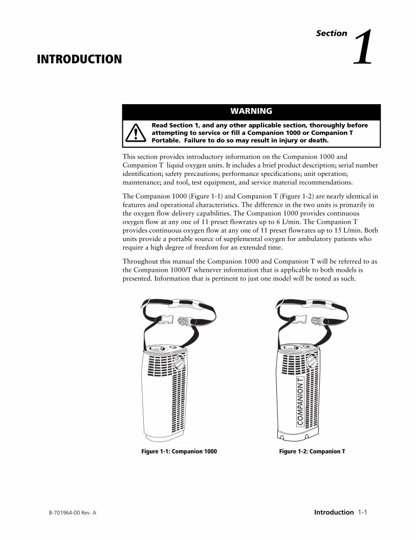
The Companion 1000 (Figure 1-1) and Companion T (Figure 1-2) are nearly identical in features and operational characteristics. The difference in the two units is primarily in the oxygen flow delivery capabilities. The Companion 1000 provides continuous oxygen flow at any one of 11 preset flowrates up to 6 L/min. The Companion T provides continuous oxygen flow at any one of 11 preset flowrates up to 15 L/min. Both units provide a portable source of supplemental oxygen for ambulatory patients who require a high degree of freedom for an extended time.
Throughout this manual the Companion 1000 and Companion T will be referred to as the Companion 1000/T whenever information that is applicable to both models is presented. Information that is pertinent to just one model will be noted as such.
Figure 1-1: Companion 1000 Figure 1-2: Companion T
WARNING
Read Section 1, and any other applicable section, thoroughly before attempting to service or fill a Companion 1000 or Companion T Portable. Failure to do so may result in injury or death.
CO
MPA
NIO
N T

Companion 1000/T Liquid Oxygen System Technical Manual
1-2 Introduction B-701964-00 Rev. A
1.1 PRODUCT DESCRIPTIONThe Companion 1000/T is a portable liquid oxygen unit that supplies supplemental medical oxygen at prescribed flowrates to the patient. A patient fills the unit with liquid oxygen from a Companion Stationary reservoir. When full, the Companion 1000/T holds about 3.1 lbs (1.4 kg) of liquid oxygen in a double-walled, vacuum-insulated container. The liquid oxygen is vaporized into gas in a heat exchange system. The gaseous oxygen is warmed to near room temperature and delivered to the patient at a selectable, metered flowrate. Flowrates up to 6 L/min are available from the Companion 1000 while flowrates up to 15 L/min are available from the Companion T. A patient will typically receive about eight hours of continuous flow oxygen at a flow setting of 2 L/min. The liquid oxygen contents of the Companion 1000/T is measured by a weight scale that is activated by suspending the unit by one end of the carrying strap. An external moisture collection cup is attached to the bottom of the Companion T. This easily removable cup collects the additional condensed water that is created when the Companion T is operated at higher flowrates.
1.2 SERIAL NUMBER IDENTIFICATION
The serial number on a Companion 1000/T is etched on the vent valve mounting bracket (Figure 1-3). The vent valve lever must be pulled down to view the serial number when the unit side covers are in place. The serial number designates the year, month, and day of manufacture as well as the production number.
Figure 1-3: Serial Number Location
Containers manufactured prior to January 1985:
Containers manufactured from January 1985 through September 1994:
Containers manufactured after September 1994:
90040846
������������
�� �����
���������������
������������� �� �����
������������������������
������������
��������������
������������� �� ����
������������������������
������������
������������� ������ ��� �� ������ ������ ��� �������
������������� ������ !�
B-701964-00 Rev. A Introduction 1-3
Companion 1000/T Liquid Oxygen System Technical Manual
1.3 SAFETY PRECAUTIONS
This section covers precautions and safe practices as they apply to facilities and personnel involved in servicing medical oxygen equipment. These precautions are divided into three main areas: cold safety, expansion safety, and fire safety. To ensure reliability and safety, the service techniques, work area, and equipment used in the storage, service, and handling of this system must be of the highest standard. Refer to the Companion Liquid Oxygen Systems Operating Instructions (B-701417-00) for additional safety precautions regarding the use of this equipment.
1.3.1 Cold Safety
Recommended Protective Clothing:
• Heavily insulated gloves (for example, cryogenic or welding gloves). Never use gloves that are contaminated with grease or oil when working with liquid oxygen.
• Protective face shield and goggles.
• Long sleeve shirt. Wear natural fibers such as cotton or wool. Avoid synthetic materials such as polyester or rayon.
• Long pants. Never wear pants with cuffs. Liquid oxygen may become trapped and cause serious burns to skin. Wear natural fibers such as cotton or wool. Avoid synthetic materials such as polyester or rayon.
• Protective cryogenic or welding apron.
Important Facts:
• Direct exposure to liquid oxygen or exposure to its vented gas or components cooled by liquid oxygen can result in frostbite. If frostbite occurs, seek medical attention immediately.
WARNING
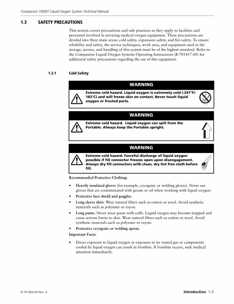
Extreme cold hazard. Liquid oxygen is extremely cold (-297°F/-183°C) and will freeze skin on contact. Never touch liquid oxygen or frosted parts.
WARNING
Extreme cold hazard. Liquid oxygen can spill from the Portable. Always keep the Portable upright.
WARNING
Extreme cold hazard. Forceful discharge of liquid oxygen possible if fill connector freezes open upon disengagement. Always dry fill connectors with clean, dry lint free cloth before fill.
Companion 1000/T Liquid Oxygen System Technical Manual
1-4 Introduction B-701964-00 Rev. A
1.3.2 Expansion Safety
Important Facts:
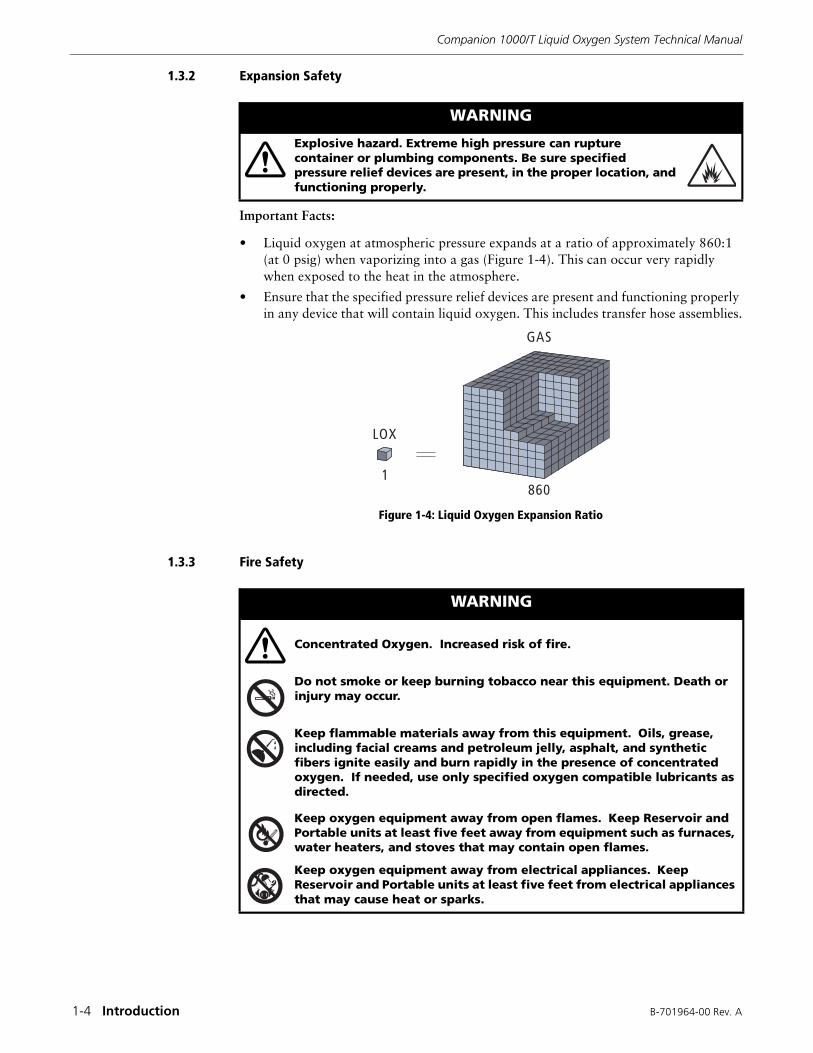
• Liquid oxygen at atmospheric pressure expands at a ratio of approximately 860:1 (at 0 psig) when vaporizing into a gas (Figure 1-4). This can occur very rapidly when exposed to the heat in the atmosphere.
• Ensure that the specified pressure relief devices are present and functioning properly in any device that will contain liquid oxygen. This includes transfer hose assemblies.
Figure 1-4: Liquid Oxygen Expansion Ratio
1.3.3 Fire Safety
WARNING
Explosive hazard. Extreme high pressure can rupture container or plumbing components. Be sure specified pressure relief devices are present, in the proper location, and functioning properly.
���
���
���
WARNING
Concentrated Oxygen. Increased risk of fire.
Do not smoke or keep burning tobacco near this equipment. Death or injury may occur.
Keep flammable materials away from this equipment. Oils, grease, including facial creams and petroleum jelly, asphalt, and synthetic fibers ignite easily and burn rapidly in the presence of concentrated oxygen. If needed, use only specified oxygen compatible lubricants as directed.
Keep oxygen equipment away from open flames. Keep Reservoir and Portable units at least five feet away from equipment such as furnaces, water heaters, and stoves that may contain open flames.
Keep oxygen equipment away from electrical appliances. Keep Reservoir and Portable units at least five feet from electrical appliances that may cause heat or sparks.
B-701964-00 Rev. A Introduction 1-5
Companion 1000/T Liquid Oxygen System Technical Manual
Important Facts:
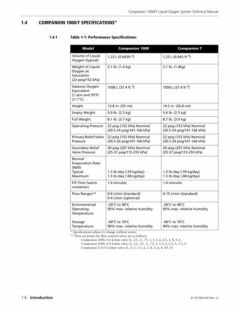
The possibility of fire exists when the combination of a fuel, source of ignition, and oxygen is present (Figure 1-5). High concentrations of oxygen (air is approximately 21% oxygen) greatly enhance the possibility of combustion.
• Obtain all replacement parts for medical oxygen equipment from the manufacturer.
• Before servicing, clean all tools that come into contact with the oxygen system.
• Use only recommended oxygen compatible cleaning and leak detection products.
• Keep the Portable and Reservoir upright at all times. Secure liquid oxygen equipment when transporting to prevent accidental tipover and spillage.
• If a liquid oxygen spill occurs indoors, open doors and windows to ventilate the area. Avoid sources of ignition and do not walk on or roll equipment over the affected area.
• Any clothing or porous material that is splashed with liquid oxygen or otherwise absorbs high concentrations of oxygen should be removed and aired for at least one hour away from any source of ignition.
Figure 1-5: Combustion Triangle
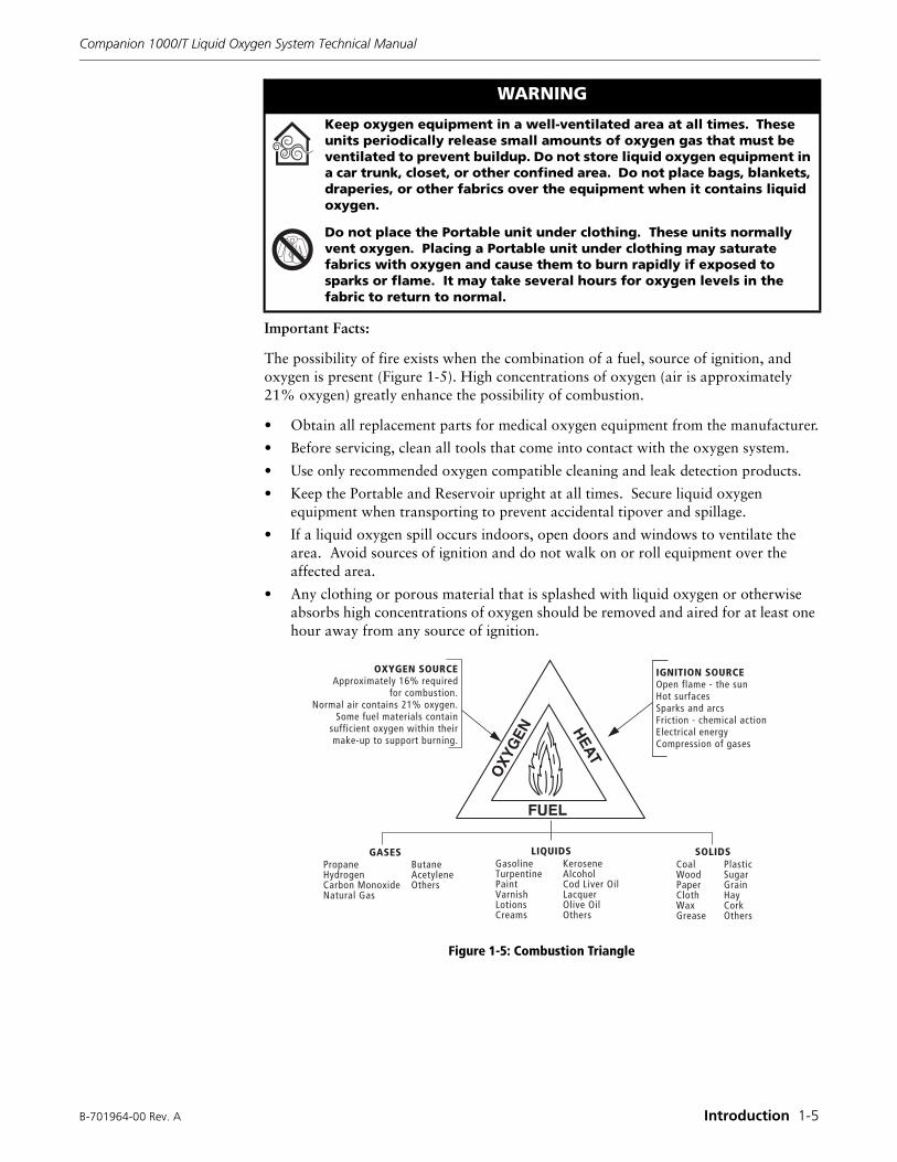
Keep oxygen equipment in a well-ventilated area at all times. These units periodically release small amounts of oxygen gas that must be ventilated to prevent buildup. Do not store liquid oxygen equipment in a car trunk, closet, or other confined area. Do not place bags, blankets, draperies, or other fabrics over the equipment when it contains liquid oxygen.
Do not place the Portable unit under clothing. These units normally vent oxygen. Placing a Portable unit under clothing may saturate fabrics with oxygen and cause them to burn rapidly if exposed to sparks or flame. It may take several hours for oxygen levels in the fabric to return to normal.
WARNING
OXYGEN SOURCEApproximately 16% required
for combustion.Normal air contains 21% oxygen.
Some fuel materials containsufficient oxygen within theirmake-up to support burning.
IGNITION SOURCEOpen flame - the sunHot surfacesSparks and arcsFriction - chemical actionElectrical energyCompression of gases
SOLIDSCoal PlasticWood SugarPaper GrainCloth HayWax CorkGrease Others
LIQUIDSGasoline KeroseneTurpentine AlcoholPaint Cod Liver OilVarnish LacquerLotions Olive OilCreams Others
GASESPropane ButaneHydrogen AcetyleneCarbon Monoxide OthersNatural Gas
Companion 1000/T Liquid Oxygen System Technical Manual
1-6 Introduction B-701964-00 Rev. A
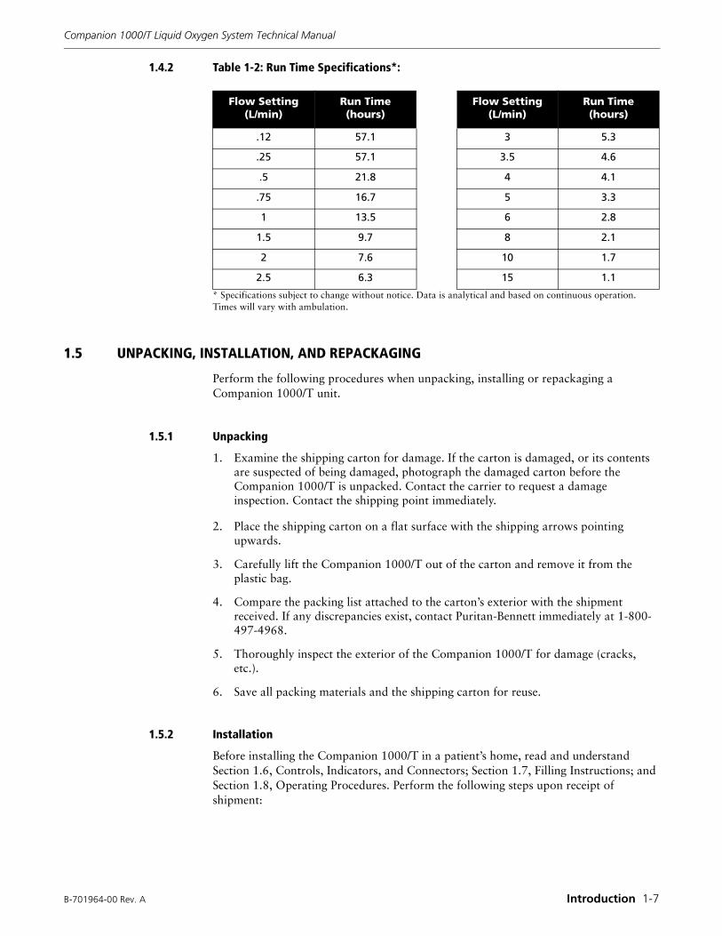
1.4 COMPANION 1000/T SPECIFICATIONS*
1.4.1 Table 1-1: Performance Specifications:
* Specifications subject to change without notice.** Flow set points for flow control valves are as follows:
Companion 1000, 0-6 L/min valve: 0, .25, .5, .75, 1, 1.5, 2, 2.5, 3, 4, 5, 6Companion 1000, 0-4 L/min valve: 0, .12, .25, .5, .75, 1, 1.5, 2, 2.5, 3, 3.5, 4Companion T, 0-15 L/min valve: 0, .5, 1, 1.5, 2, 3, 4, 5, 6, 8, 10, 15
Model Companion 1000 Companion T
Volume of Liquid Oxygen (typical)
1.23 L (0.043ft 3) 1.23 L (0.043 ft 3)
Weight of Liquid Oxygen at Saturation (22 psig/152 kPa)
3.1 lb. (1.4 kg) 3.1 lb. (1.4kg)
Gaseous Oxygen Equivalent(1 atm and 70°F/21.1°C)
1058 L (37.4 ft 3) 1058 L (37.4 ft 3)
Height 13.8 in. (35 cm) 14.5 in. (36.8 cm)
Empty Weight 5.0 lb. (2.3 kg) 5.6 lb. (2.5 kg)
Full Weight 8.1 lb. (3.7 kg) 8.7 lb. (3.9 kg)
Operating Pressure 22 psig (152 kPa) Nominal(20.5-24 psig/141-166 kPa)
22 psig (152 kPa) Nominal(20.5-24 psig/141-166 kPa)
Primary Relief Valve Pressure
22 psig (152 kPa) Nominal(20.5-24 psig/141-166 kPa)
22 psig (152 kPa) Nominal(20.5-24 psig/141-166 kPa)
Secondary Relief Valve Pressure
30 psig (207 kPa) Nominal(25-37 psig/172-255 kPa)
30 psig (207 kPa) Nominal(25-37 psig/172-255 kPa)
Normal Evaporation Rate (NER)Typical:Maximum:
1.3 lb./day (.59 kg/day)1.5 lb./day (.68 kg/day)
1.3 lb./day (.59 kg/day)1.5 lb./day (.68 kg/day)
Fill Time (warm container)
1.4 minutes 1.4 minutes
Flow Ranges** 0-6 L/min (standard)0-4 L/min (optional)
0-15 L/min (standard)
Environmental Operating Temperature:
Storage Temperature:
-20°C to 40°C95% max. relative humidity
-40°C to 70°C90% max. relative humidity
-20°C to 40°C95% max. relative humidity
-40°C to 70°C90% max. relative humidity
B-701964-00 Rev. A Introduction 1-7
Companion 1000/T Liquid Oxygen System Technical Manual
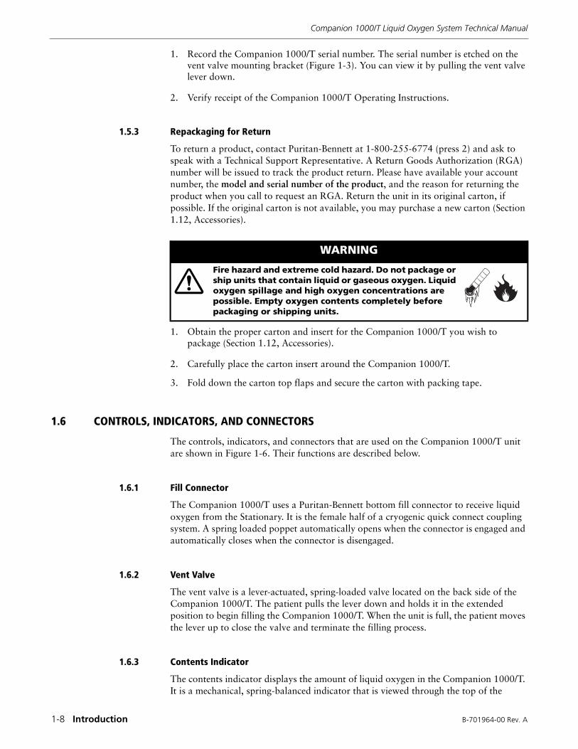
1.4.2 Table 1-2: Run Time Specifications*:
* Specifications subject to change without notice. Data is analytical and based on continuous operation. Times will vary with ambulation.
1.5 UNPACKING, INSTALLATION, AND REPACKAGING
Perform the following procedures when unpacking, installing or repackaging a Companion 1000/T unit.
1.5.1 Unpacking
1. Examine the shipping carton for damage. If the carton is damaged, or its contents are suspected of being damaged, photograph the damaged carton before the Companion 1000/T is unpacked. Contact the carrier to request a damage inspection. Contact the shipping point immediately.
2. Place the shipping carton on a flat surface with the shipping arrows pointing upwards.
3. Carefully lift the Companion 1000/T out of the carton and remove it from the plastic bag.
4. Compare the packing list attached to the carton’s exterior with the shipment received. If any discrepancies exist, contact Puritan-Bennett immediately at 1-800-497-4968.
5. Thoroughly inspect the exterior of the Companion 1000/T for damage (cracks, etc.).
6. Save all packing materials and the shipping carton for reuse.
1.5.2 Installation
Before installing the Companion 1000/T in a patient’s home, read and understand Section 1.6, Controls, Indicators, and Connectors; Section 1.7, Filling Instructions; and Section 1.8, Operating Procedures. Perform the following steps upon receipt of shipment:
Flow Setting (L/min)
Run Time(hours)
Flow Setting(L/min)
Run Time(hours)
.12 57.1 3 5.3
.25 57.1 3.5 4.6
.5 21.8 4 4.1
.75 16.7 5 3.3
1 13.5 6 2.8
1.5 9.7 8 2.1
2 7.6 10 1.7
2.5 6.3 15 1.1
Companion 1000/T Liquid Oxygen System Technical Manual
1-8 Introduction B-701964-00 Rev. A
1. Record the Companion 1000/T serial number. The serial number is etched on the vent valve mounting bracket (Figure 1-3). You can view it by pulling the vent valve lever down.
2. Verify receipt of the Companion 1000/T Operating Instructions.
1.5.3 Repackaging for Return
To return a product, contact Puritan-Bennett at 1-800-255-6774 (press 2) and ask to speak with a Technical Support Representative. A Return Goods Authorization (RGA) number will be issued to track the product return. Please have available your account number, the model and serial number of the product, and the reason for returning the product when you call to request an RGA. Return the unit in its original carton, if possible. If the original carton is not available, you may purchase a new carton (Section 1.12, Accessories).
1. Obtain the proper carton and insert for the Companion 1000/T you wish to package (Section 1.12, Accessories).
2. Carefully place the carton insert around the Companion 1000/T.
3. Fold down the carton top flaps and secure the carton with packing tape.
1.6 CONTROLS, INDICATORS, AND CONNECTORS
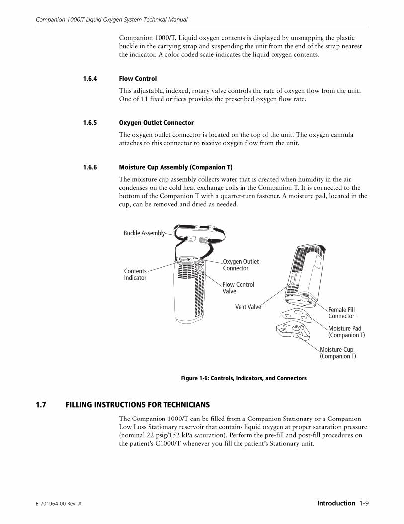
The controls, indicators, and connectors that are used on the Companion 1000/T unit are shown in Figure 1-6. Their functions are described below.
1.6.1 Fill Connector
The Companion 1000/T uses a Puritan-Bennett bottom fill connector to receive liquid oxygen from the Stationary. It is the female half of a cryogenic quick connect coupling system. A spring loaded poppet automatically opens when the connector is engaged and automatically closes when the connector is disengaged.
1.6.2 Vent Valve
The vent valve is a lever-actuated, spring-loaded valve located on the back side of the Companion 1000/T. The patient pulls the lever down and holds it in the extended position to begin filling the Companion 1000/T. When the unit is full, the patient moves the lever up to close the valve and terminate the filling process.
1.6.3 Contents Indicator
The contents indicator displays the amount of liquid oxygen in the Companion 1000/T. It is a mechanical, spring-balanced indicator that is viewed through the top of the
WARNING
Fire hazard and extreme cold hazard. Do not package or ship units that contain liquid or gaseous oxygen. Liquid oxygen spillage and high oxygen concentrations are possible. Empty oxygen contents completely before packaging or shipping units.
B-701964-00 Rev. A Introduction 1-9
Companion 1000/T Liquid Oxygen System Technical Manual
Companion 1000/T. Liquid oxygen contents is displayed by unsnapping the plastic buckle in the carrying strap and suspending the unit from the end of the strap nearest the indicator. A color coded scale indicates the liquid oxygen contents.
1.6.4 Flow Control
This adjustable, indexed, rotary valve controls the rate of oxygen flow from the unit. One of 11 fixed orifices provides the prescribed oxygen flow rate.
1.6.5 Oxygen Outlet Connector
The oxygen outlet connector is located on the top of the unit. The oxygen cannula attaches to this connector to receive oxygen flow from the unit.
1.6.6 Moisture Cup Assembly (Companion T)
The moisture cup assembly collects water that is created when humidity in the air condenses on the cold heat exchange coils in the Companion T. It is connected to the bottom of the Companion T with a quarter-turn fastener. A moisture pad, located in the cup, can be removed and dried as needed.
Figure 1-6: Controls, Indicators, and Connectors
1.7 FILLING INSTRUCTIONS FOR TECHNICIANS
The Companion 1000/T can be filled from a Companion Stationary or a Companion Low Loss Stationary reservoir that contains liquid oxygen at proper saturation pressure (nominal 22 psig/152 kPa saturation). Perform the pre-fill and post-fill procedures on the patient’s C1000/T whenever you fill the patient’s Stationary unit.
Buckle Assembly
Vent Valve
ContentsIndicator
Oxygen OutletConnector
Flow ControlValve
Female FillConnector
Moisture Pad(Companion T)
Moisture Cup(Companion T)
Companion 1000/T Liquid Oxygen System Technical Manual
1-10 Introduction B-701964-00 Rev. A
1.7.1 Pre-Fill Inspection
Perform the following procedure to visually inspect the Companion 1000/T and determine its operational status before filling. Correct observed problems before proceeding to fill the unit.
1. Visually inspect the Companion 1000/T unit for overall product integrity (for example, cracked or damaged components).
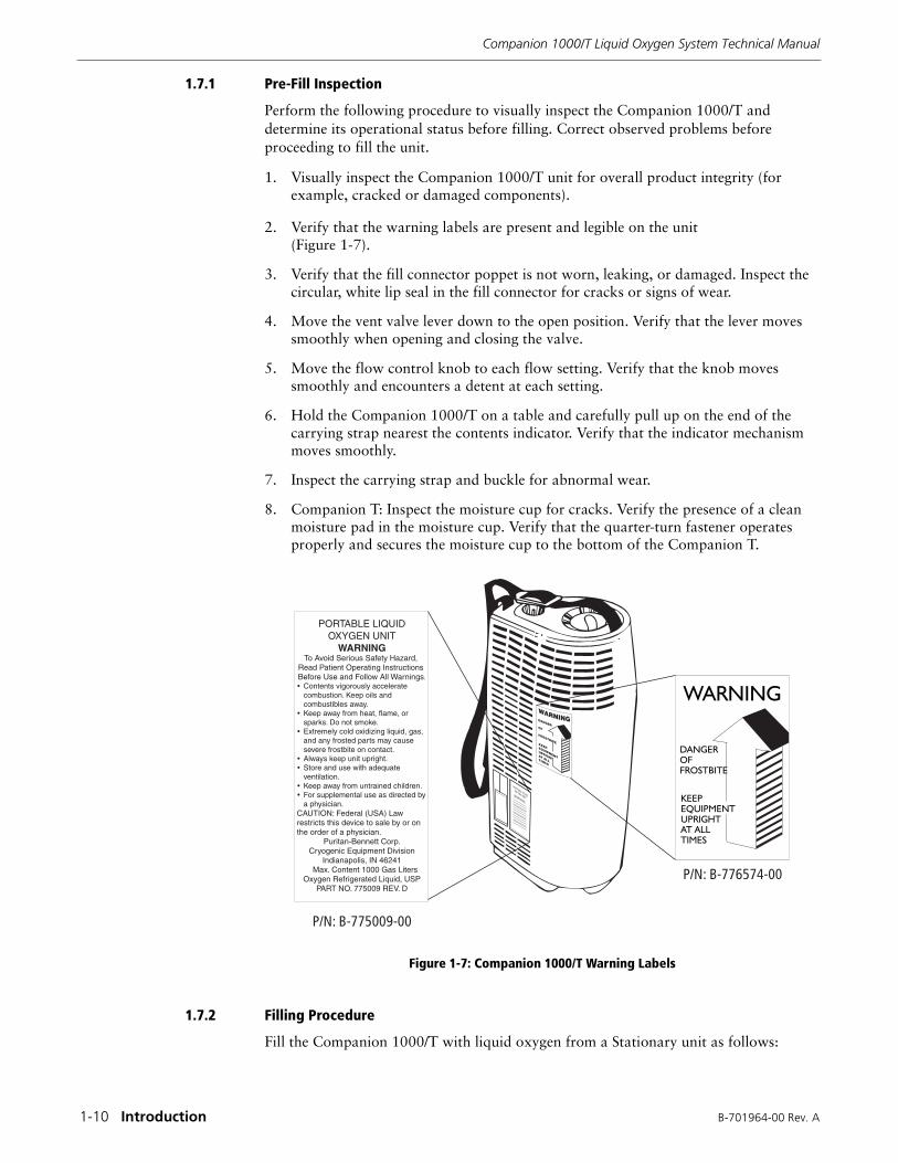
2. Verify that the warning labels are present and legible on the unit (Figure 1-7).
3. Verify that the fill connector poppet is not worn, leaking, or damaged. Inspect the circular, white lip seal in the fill connector for cracks or signs of wear.
4. Move the vent valve lever down to the open position. Verify that the lever moves smoothly when opening and closing the valve.
5. Move the flow control knob to each flow setting. Verify that the knob moves smoothly and encounters a detent at each setting.
6. Hold the Companion 1000/T on a table and carefully pull up on the end of the carrying strap nearest the contents indicator. Verify that the indicator mechanism moves smoothly.
7. Inspect the carrying strap and buckle for abnormal wear.
8. Companion T: Inspect the moisture cup for cracks. Verify the presence of a clean moisture pad in the moisture cup. Verify that the quarter-turn fastener operates properly and secures the moisture cup to the bottom of the Companion T.
Figure 1-7: Companion 1000/T Warning Labels
1.7.2 Filling Procedure
Fill the Companion 1000/T with liquid oxygen from a Stationary unit as follows:
PORTABLE LIQUIDOXYGEN UNIT
WARNINGTo Avoid Serious Safety Hazard,
Read Patient Operating Instructions Before Use and Follow All Warnings.��Contents vigorously accelerate
combustion. Keep oils and combustibles away.
��Keep away from heat, flame, or sparks. Do not smoke.
��Extremely cold oxidizing liquid, gas, and any frosted parts may cause severe frostbite on contact.
��Always keep unit upright.��Store and use with adequate
ventilation.��Keep away from untrained children.��For supplemental use as directed by
a physician.CAUTION: Federal (USA) Law restricts this device to sale by or on the order of a physician.
Puritan-Bennett Corp.Cryogenic Equipment Division
Indianapolis, IN 46241Max. Content 1000 Gas Liters
Oxygen Refrigerated Liquid, USPPART NO. 775009 REV. D
���� ������
���� ���������
B-701964-00 Rev. A Introduction 1-11
Companion 1000/T Liquid Oxygen System Technical Manual
1. Companion T: Remove the moisture cup from the bottom of the unit.
2. Using a clean, dry, lint-free cloth, dry the male fill connector on the Stationary and the female fill connector on the Companion 1000/T.
3. Check the Stationary contents indicator to make sure there is enough liquid oxygen for the filling operation.
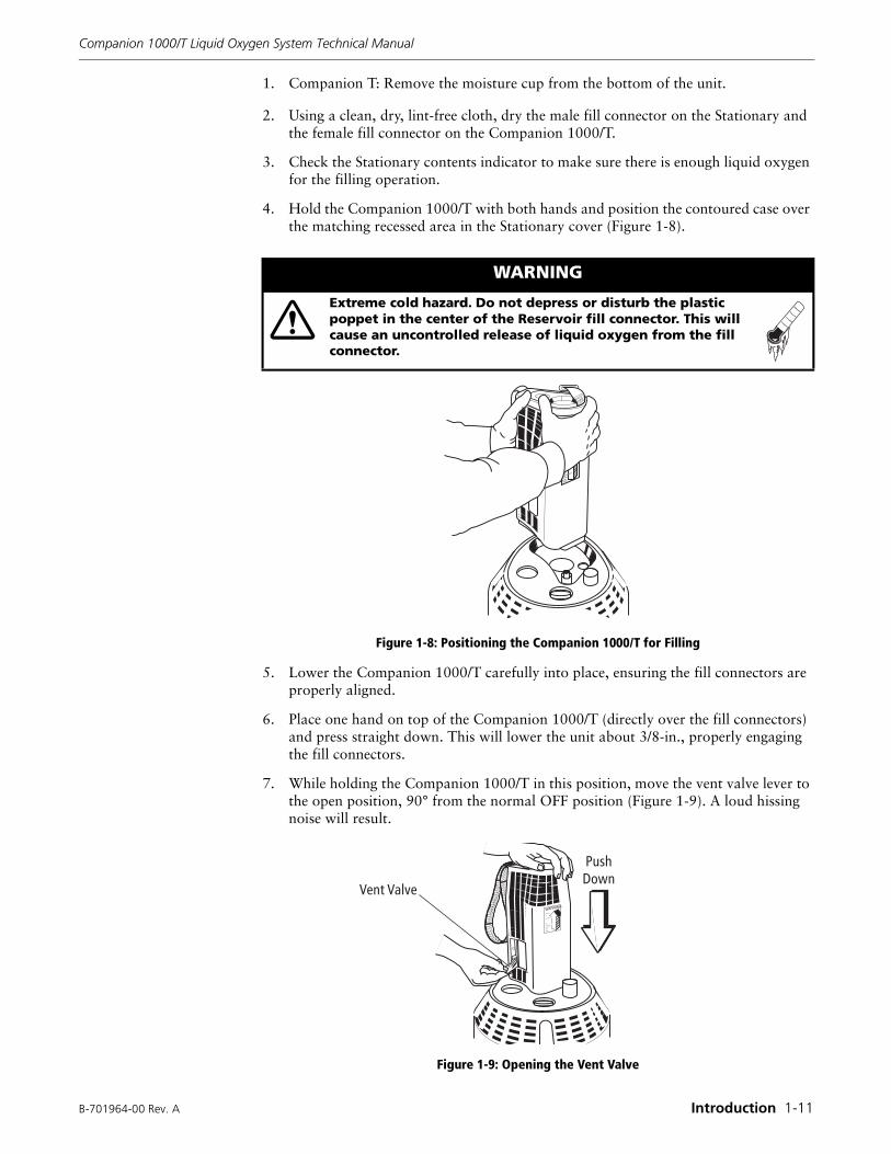
4. Hold the Companion 1000/T with both hands and position the contoured case over the matching recessed area in the Stationary cover (Figure 1-8).
Figure 1-8: Positioning the Companion 1000/T for Filling
5. Lower the Companion 1000/T carefully into place, ensuring the fill connectors are properly aligned.
6. Place one hand on top of the Companion 1000/T (directly over the fill connectors) and press straight down. This will lower the unit about 3/8-in., properly engaging the fill connectors.
7. While holding the Companion 1000/T in this position, move the vent valve lever to the open position, 90° from the normal OFF position (Figure 1-9). A loud hissing noise will result.
Figure 1-9: Opening the Vent Valve
WARNING
Extreme cold hazard. Do not depress or disturb the plastic poppet in the center of the Reservoir fill connector. This will cause an uncontrolled release of liquid oxygen from the fill connector.
WARNING
KEEP
EQUIPME
NT
UPRIGHT
ATALL
TIMES
DANGER
OF
FROSTBI
TE
���� �����
��
� ��
Companion 1000/T Liquid Oxygen System Technical Manual
1-12 Introduction B-701964-00 Rev. A
8. When you notice a change in the sound of the venting gas, followed by the emission of a dense, white vapor around the Stationary shroud, close the vent valve. Fill times may vary according to the temperature of the container before filling and the Stationary pressure. Maximum fill time is approximately 1 3/4 minutes.
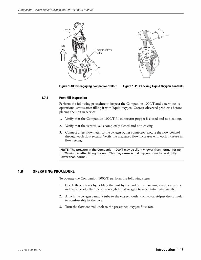
9. Disengage the Companion 1000/T from the Stationary by holding the carrying strap above the unit and pressing the release button (Figure 1-10). Always hold the Companion 1000/T with one hand when attempting to disengage it. Should the units not disengage easily, they may be frozen together. Do not use force. Allow a few moments for the frozen parts to warm. Disengage the units after the ice has melted.
10. Check the liquid oxygen contents indicator. The amount of liquid oxygen in the Companion 1000/T is measured by an internal scale on top of the unit. Actuate the scale by lifting the unit by the strap nearest the indicator. The color-coded gauge indicates the liquid level (Figure 1-11).
WARNING
Extreme cold hazard. Do not leave the Companion 1000/T unattended during the filling operation. Excessive liquid oxygen discharge can occur.
NOTE: During the filling operation, maintain a slight downward pressure on the Companion 1000/T with one hand to ensure stability and proper filling position. Approximately 20-30 seconds into the fill, close and reopen the vent valve one or more times to prevent the vent valve from freezing open.
CAUTION:If the vent valve fails to close and the hissing continues, remove the Companion 1000/T by pressing the release button on the Stationary (Figure 1-10). Keep the Companion 1000/T in an upright position. The unit will stop venting in a few minutes. Allow the unit to warm until you can close the vent valve. It may require as much as two to three hours with the flow control off for the Companion 1000/T to restore adequate pressure for accurate oxygen delivery.
WARNING
Extreme cold hazard. Liquid oxygen discharge from the fill connector can occur. When disconnecting the Companion 1000/T, never stand directly over the Stationary fill connector. If the Stationary fill connector stays open and minor liquid oxygen discharge occurs, carefully re-engage and disengage the Companion 1000/T to help dislodge any ice or other obstruction. If major liquid oxygen discharge (steady stream) occurs, open the reservoir vent valve (if safely possible) to vent pressure and stop the release of liquid oxygen. Open windows and doors to ventilate the room. Do not walk on areas exposed to liquid oxygen for 60 minutes after frost disappears.
NOTE: Disengage the plastic buckle in the carrying strap before checking liquid oxygen contents level.
B-701964-00 Rev. A Introduction 1-13
Companion 1000/T Liquid Oxygen System Technical Manual
Figure 1-10: Disengaging Companion 1000/T Figure 1-11: Checking Liquid Oxygen Contents
1.7.3 Post-Fill Inspection
Perform the following procedure to inspect the Companion 1000/T and determine its operational status after filling it with liquid oxygen. Correct observed problems before placing the unit in service.
1. Verify that the Companion 1000/T fill connector poppet is closed and not leaking.
2. Verify that the vent valve is completely closed and not leaking.
3. Connect a test flowmeter to the oxygen outlet connector. Rotate the flow control through each flow setting. Verify the measured flow increases with each increase in flow setting.
1.8 OPERATING PROCEDURE
To operate the Companion 1000/T, perform the following steps:
1. Check the contents by holding the unit by the end of the carrying strap nearest the indicator. Verify that there is enough liquid oxygen to meet anticipated needs.
2. Attach the oxygen cannula tube to the oxygen outlet connector. Adjust the cannula to comfortably fit the face.
3. Turn the flow control knob to the prescribed oxygen flow rate.
����
������ ��
������
NOTE: The pressure in the Companion 1000/T may be slightly lower than normal for up to 20 minutes after filling the unit. This may cause actual oxygen flows to be slightly lower than normal.
Companion 1000/T Liquid Oxygen System Technical Manual
1-14 Introduction B-701964-00 Rev. A
1.9 MAINTENANCE
The Companion 1000/T Pre-Fill Inspection, Filling, and Post-Fill Inspection procedures should be performed every time the patient’s Stationary reservoir is filled. This provides routine assessment of the functional status of the Companion 1000/T. Functional problems observed during these procedures must be corrected before placing the unit in service.
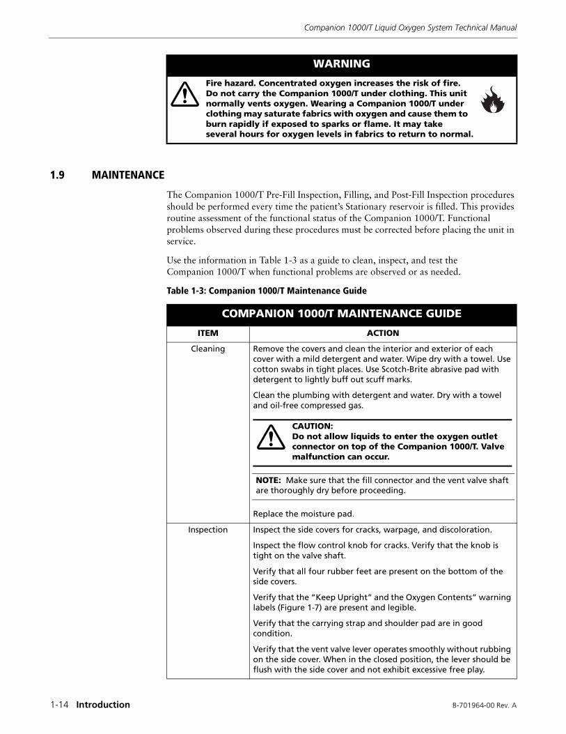
Use the information in Table 1-3 as a guide to clean, inspect, and test the Companion 1000/T when functional problems are observed or as needed.
Table 1-3: Companion 1000/T Maintenance Guide
WARNING
Fire hazard. Concentrated oxygen increases the risk of fire. Do not carry the Companion 1000/T under clothing. This unit normally vents oxygen. Wearing a Companion 1000/T under clothing may saturate fabrics with oxygen and cause them to burn rapidly if exposed to sparks or flame. It may take several hours for oxygen levels in fabrics to return to normal.
COMPANION 1000/T MAINTENANCE GUIDE
ITEM ACTION
Cleaning Remove the covers and clean the interior and exterior of each cover with a mild detergent and water. Wipe dry with a towel. Use cotton swabs in tight places. Use Scotch-Brite abrasive pad with detergent to lightly buff out scuff marks.
Clean the plumbing with detergent and water. Dry with a towel and oil-free compressed gas.
Replace the moisture pad.
Inspection Inspect the side covers for cracks, warpage, and discoloration.
Inspect the flow control knob for cracks. Verify that the knob is tight on the valve shaft.
Verify that all four rubber feet are present on the bottom of the side covers.
Verify that the “Keep Upright” and the Oxygen Contents” warning labels (Figure 1-7) are present and legible.
Verify that the carrying strap and shoulder pad are in good condition.
Verify that the vent valve lever operates smoothly without rubbing on the side cover. When in the closed position, the lever should be flush with the side cover and not exhibit excessive free play.
CAUTION:Do not allow liquids to enter the oxygen outlet connector on top of the Companion 1000/T. Valve malfunction can occur.
NOTE: Make sure that the fill connector and the vent valve shaft are thoroughly dry before proceeding.
B-701964-00 Rev. A Introduction 1-15
Companion 1000/T Liquid Oxygen System Technical Manual
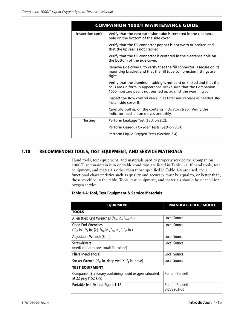
1.10 RECOMMENDED TOOLS, TEST EQUIPMENT, AND SERVICE MATERIALS
Hand tools, test equipment, and materials used to properly service the Companion 1000/T and maintain it in operable condition are listed in Table 1-4. If hand tools, test equipment, and materials other than those specified in Table 1-4 are used, their functional characteristics such as quality and accuracy must be equal to, or better than, those specified in the table. Tools, test equipment, and materials should be cleaned for oxygen service.
Table 1-4: Tool, Test Equipment & Service Materials
Inspection con’t Verify that the vent extension tube is centered in the clearance hole on the bottom of the side cover.
Verify that the fill connector poppet is not worn or broken and that the lip seal is not cracked.
Verify that the fill connector is centered in the clearance hole on the bottom of the side cover.
Remove side cover B to verify that the fill connector is secure on its mounting bracket and that the fill tube compression fittings are tight.
Verify that the aluminum tubing is not bent or kinked and that the coils are uniform in appearance. Make sure that the Companion 1000 moisture pad is not pushed up against the warming coil.
Inspect the flow control valve inlet filter and replace as needed. Re-install side cover B.
Carefully pull up on the contents indicator strap. Verify the indicator mechanism moves smoothly.
Testing Perform Leakage Test (Section 3.2).
Perform Gaseous Oxygen Tests (Section 3.3).
Perform Liquid Oxygen Tests (Section 3.4).
COMPANION 1000/T MAINTENANCE GUIDE
EQUIPMENT MANUFACTURER / MODEL
TOOLS
Allen (Hex Key) Wrenches (1/16 in., 7/64 in.) Local Source
Open End Wrenches (7/16 in., 1/2 in. [2], 9/16 in., 5/8 in., 11/16 in.)
Local Source
Adjustable Wrench (8 in.) Local Source
Screwdrivers (medium flat-blade, small flat-blade)
Local Source
Pliers (needlenose) Local Source
Socket Wrench (5/16 in. deep well X 1/4 in. drive) Local Source
TEST EQUIPMENT
Companion Stationary containing liquid oxygen saturated at 22 psig (152 kPa)
Puritan-Bennett
Portable Test Fixture, Figure 1-12 Puritan-BennettB-778202-00
Companion 1000/T Liquid Oxygen System Technical Manual
1-16 Introduction B-701964-00 Rev. A
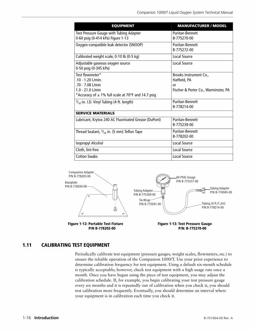
Figure 1-12: Portable Test Fixture Figure 1-13: Test Pressure GaugeP/N B-778202-00 P/N: B-775270-00
1.11 CALIBRATING TEST EQUIPMENT
Periodically calibrate test equipment (pressure gauges, weight scales, flowmeters, etc.) to ensure the reliable operation of the Companion 1000/T. Use your prior experience to determine calibration frequency for test equipment. Using a default six-month schedule is typically acceptable; however, check test equipment with a high usage rate once a month. Once you have begun using the piece of test equipment, you may adjust the calibration schedule. If, for example, you begin calibrating your test pressure gauge every six months and it is repeatedly out of calibration when you check it, you should test calibration more frequently. Eventually, you should determine an interval where your equipment is in calibration each time you check it.
Test Pressure Gauge with Tubing Adapter0-60 psig (0-414 kPa) Figure 1-13
Puritan-BennettB-775270-00
Oxygen-compatible leak detector (SNOOP) Puritan-BennettB-775272-00
Calibrated weight scale, 0-10 lb (0-5 kg) Local Source
Adjustable gaseous oxygen source0-50 psig (0-345 kPa)
Local Source
Test flowmeter*.10 - 1.20 L/min..70 - 7.08 L/min1.0 - 21.0 L/min*Accuracy of ± 1% full scale at 70°F and 14.7 psig
Brooks Instrument Co., Hatfield, PA orFischer & Porter Co., Warminster, PA
3/16-in. I.D. Vinyl Tubing (4-ft. length) Puritan-BennettB-778214-00
SERVICE MATERIALS
Lubricant, Krytox 240 AC Fluorinated Grease (DuPont) Puritan-BennettB-775239-00
Thread Sealant, 3/16 in. (5 mm) Teflon Tape Puritan-BennettB-778202-00
Isopropyl Alcohol Local Source
Cloth, lint-free Local Source
Cotton Swabs Local Source
EQUIPMENT MANUFACTURER / MODEL
��������� ����� �� �����������
�������� �� �����������
�� ���� ����� �����������
����� �������� �����������
����� �� �� �! �"#�� ����$�!����
����� �������� �����������
�� %����� �������!���
B-701964-00 Rev. A Introduction 1-17
Companion 1000/T Liquid Oxygen System Technical Manual
Before using any piece of test equipment that has been dropped or mishandled, always perform a calibration check. Test instruments that are used to test the performance of the Companion 1000/T can be sent to an accredited calibration lab for calibration testing. Another option is to keep a calibrated master test instrument (pressure gauge, flowmeter, etc.) on site as a reference to check your field test instruments. Look in the telephone yellow pages under Calibration for the location of an accredited calibration lab. An example of an accredited calibration lab is:
PTS Calibrations LLC, 5603 W. Raymond St., Suite 1, Indianapolis, IN 46241Telephone: 317-487-2378
Refer to ISO 10012-1 (Quality Assurance Requirements for Measuring Equipment) for additional information.
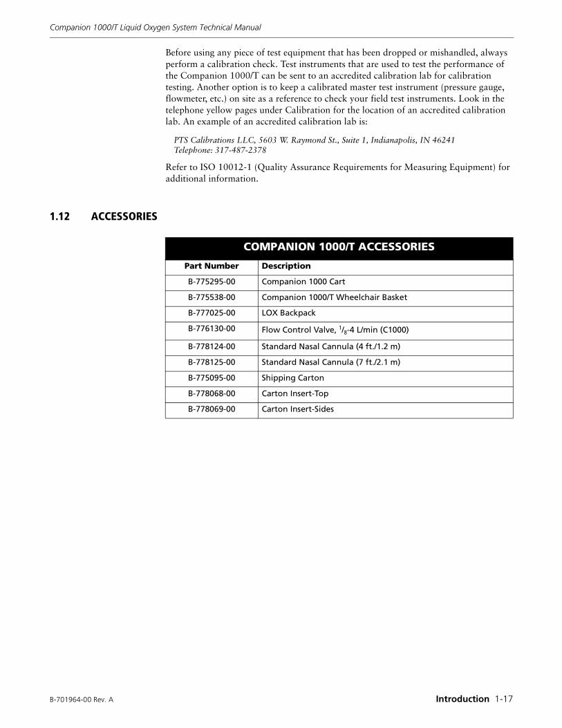
1.12 ACCESSORIES
COMPANION 1000/T ACCESSORIES
Part Number Description
B-775295-00 Companion 1000 Cart
B-775538-00 Companion 1000/T Wheelchair Basket
B-777025-00 LOX Backpack
B-776130-00 Flow Control Valve, 1/8-4 L/min (C1000)
B-778124-00 Standard Nasal Cannula (4 ft./1.2 m)
B-778125-00 Standard Nasal Cannula (7 ft./2.1 m)
B-775095-00 Shipping Carton
B-778068-00 Carton Insert-Top
B-778069-00 Carton Insert-Sides

(Blank Page)
B-701964-00 Rev. A Theory of Operation 2-1
Section2THEORY OF OPERATION
This section describes the theory of operation for the Companion 1000/T Portable liquid oxygen unit, including system component descriptions, liquid oxygen saturation principles, and Companion 1000/T operating principles.
2.1 COMPANION 1000/T COMPONENT DESCRIPTIONS
Following is a brief description of each of the major functional components of the Companion 1000/T Portable.
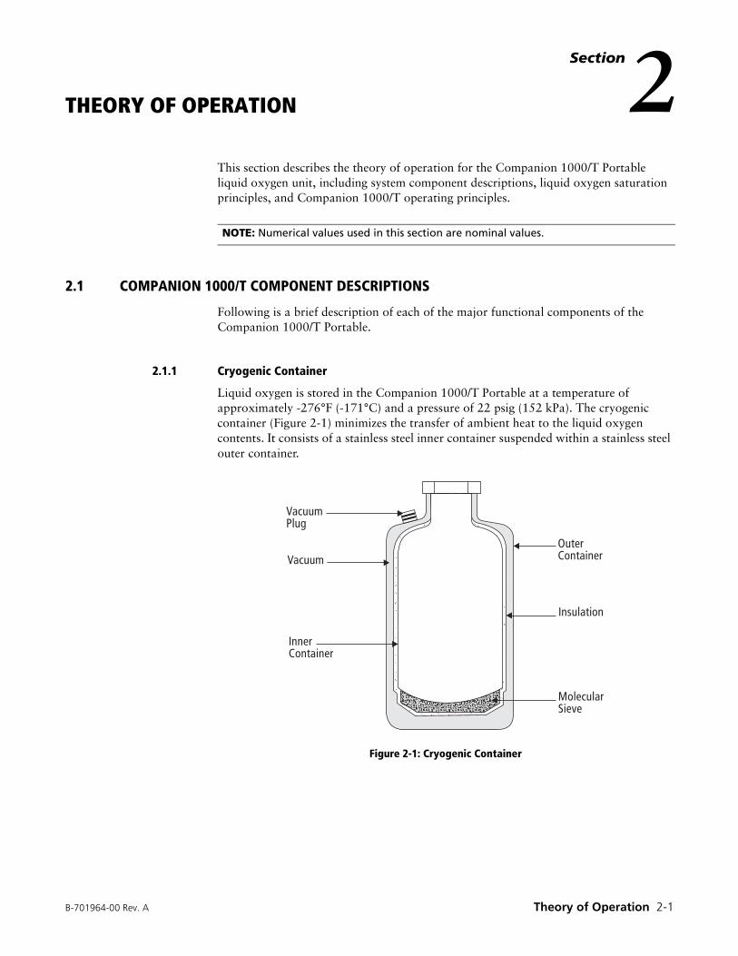
2.1.1 Cryogenic Container
Liquid oxygen is stored in the Companion 1000/T Portable at a temperature of approximately -276°F (-171°C) and a pressure of 22 psig (152 kPa). The cryogenic container (Figure 2-1) minimizes the transfer of ambient heat to the liquid oxygen contents. It consists of a stainless steel inner container suspended within a stainless steel outer container.
Figure 2-1: Cryogenic Container
NOTE: Numerical values used in this section are nominal values.
����������
������
��� ����
����� ����
�������
� ���������
Companion 1000/T Liquid Oxygen System Technical Manual
2-2 Theory of Operation B-701964-00 Rev. A
Limiting the number of contact points the inner container has with the outer container keeps conductive heat transfer to a minimum. In addition, the inner container is orbitally wrapped with multiple, alternating layers of aluminum foil and fiberglass paper. This insulation wrap reflects radiant heat from the outer container. Finally, to minimize the effects of convective heat transfer between the two containers, a vacuum is created in the annular space between the outer and inner containers. The vacuum, drawn through the evacuation port, removes most of the gas molecules in the annular space. Since no vacuum created on earth is perfect, a molecular sieve material is located in the annular space in the bottom of the inner container. When liquid oxygen in the inner container cools the molecular sieve to cryogenic temperatures, stray gas molecules are removed from the vacuum by adsorption into the sieve, thus improving the vacuum between the containers.
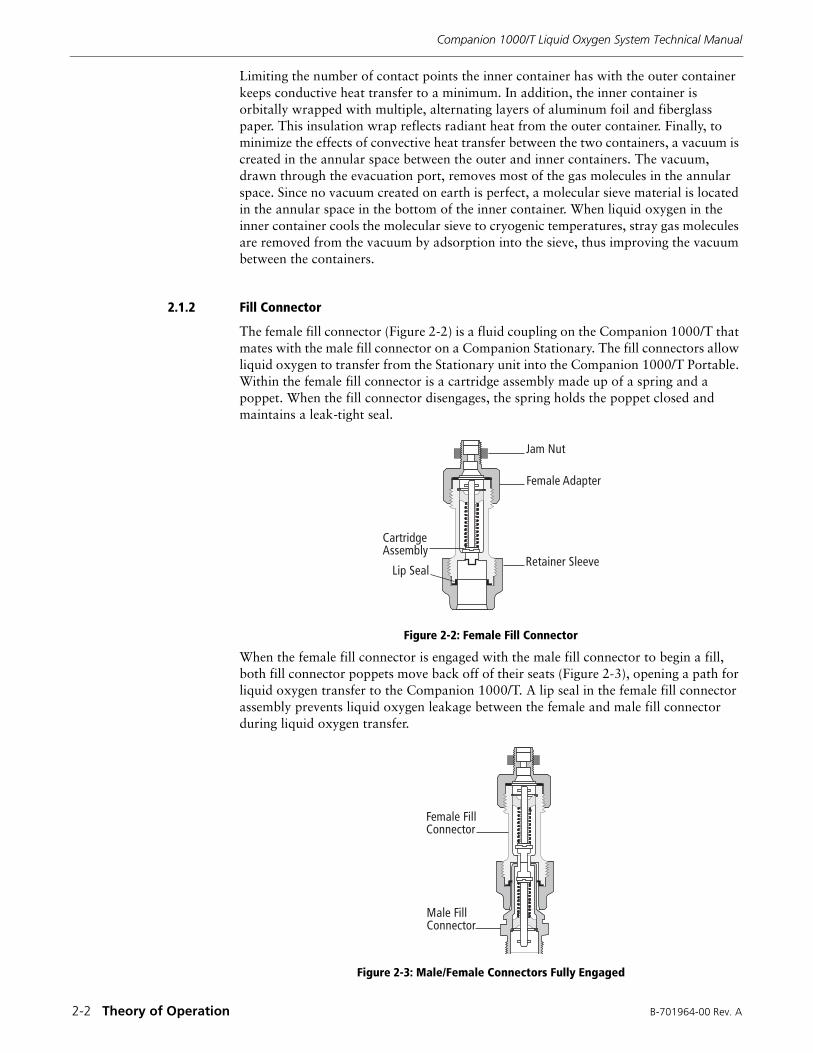
2.1.2 Fill Connector
The female fill connector (Figure 2-2) is a fluid coupling on the Companion 1000/T that mates with the male fill connector on a Companion Stationary. The fill connectors allow liquid oxygen to transfer from the Stationary unit into the Companion 1000/T Portable. Within the female fill connector is a cartridge assembly made up of a spring and a poppet. When the fill connector disengages, the spring holds the poppet closed and maintains a leak-tight seal.
Figure 2-2: Female Fill Connector
When the female fill connector is engaged with the male fill connector to begin a fill, both fill connector poppets move back off of their seats (Figure 2-3), opening a path for liquid oxygen transfer to the Companion 1000/T. A lip seal in the female fill connector assembly prevents liquid oxygen leakage between the female and male fill connector during liquid oxygen transfer.
Figure 2-3: Male/Female Connectors Fully Engaged
��� ���
����� �����
������� �����
�� � ����������
��� ���
������ ����
������
��� ����
������
B-701964-00 Rev. A Theory of Operation 2-3
Companion 1000/T Liquid Oxygen System Technical Manual
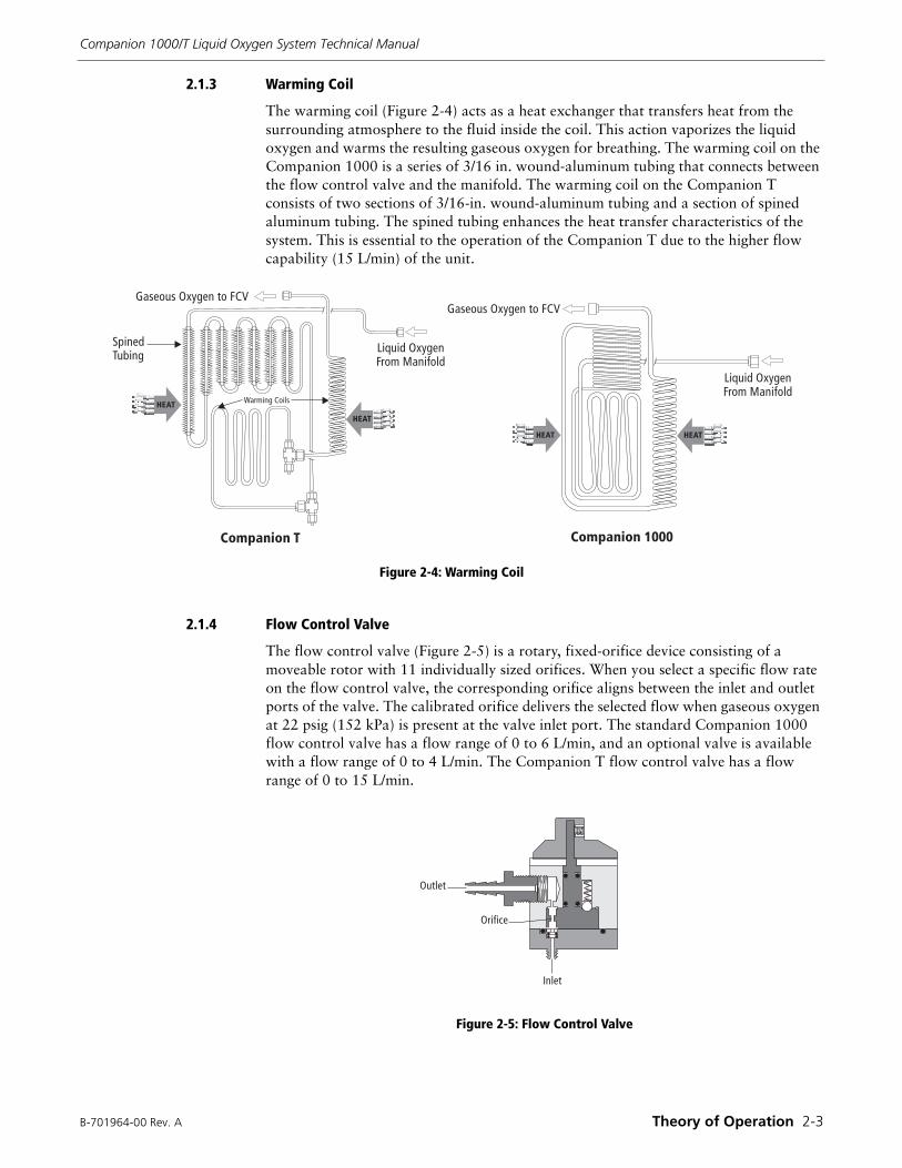
2.1.3 Warming Coil
The warming coil (Figure 2-4) acts as a heat exchanger that transfers heat from the surrounding atmosphere to the fluid inside the coil. This action vaporizes the liquid oxygen and warms the resulting gaseous oxygen for breathing. The warming coil on the Companion 1000 is a series of 3/16 in. wound-aluminum tubing that connects between the flow control valve and the manifold. The warming coil on the Companion T consists of two sections of 3/16-in. wound-aluminum tubing and a section of spined aluminum tubing. The spined tubing enhances the heat transfer characteristics of the system. This is essential to the operation of the Companion T due to the higher flow capability (15 L/min) of the unit.
Figure 2-4: Warming Coil
2.1.4 Flow Control Valve
The flow control valve (Figure 2-5) is a rotary, fixed-orifice device consisting of a moveable rotor with 11 individually sized orifices. When you select a specific flow rate on the flow control valve, the corresponding orifice aligns between the inlet and outlet ports of the valve. The calibrated orifice delivers the selected flow when gaseous oxygen at 22 psig (152 kPa) is present at the valve inlet port. The standard Companion 1000 flow control valve has a flow range of 0 to 6 L/min, and an optional valve is available with a flow range of 0 to 4 L/min. The Companion T flow control valve has a flow range of 0 to 15 L/min.
Figure 2-5: Flow Control Valve
����
����
����
����
�����������
��� �� ����� � ������ �� ����� � ���
������ ������� � ����� ��
������ ������� � ����� ��
������ � ���
������ � ������ �
�����
������
�����
Companion 1000/T Liquid Oxygen System Technical Manual
2-4 Theory of Operation B-701964-00 Rev. A
2.1.5 Vent Valve
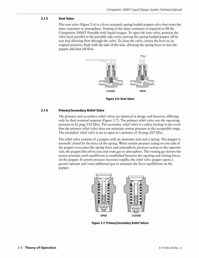
The vent valve (Figure 2-6) is a lever-actuated, spring-loaded poppet valve that vents the inner container to atmosphere. Venting of the inner container is required to fill the Companion 1000/T Portable with liquid oxygen. To open the vent valve, position the valve lever parallel to the portable side cover, moving the spring-loaded poppet off its seat and allowing flow through the valve. To close the valve, return the lever to its original position, flush with the side of the unit, allowing the spring force to seat the poppet and shut off flow.
Figure 2-6: Vent Valve
2.1.6 Primary/Secondary Relief Valve
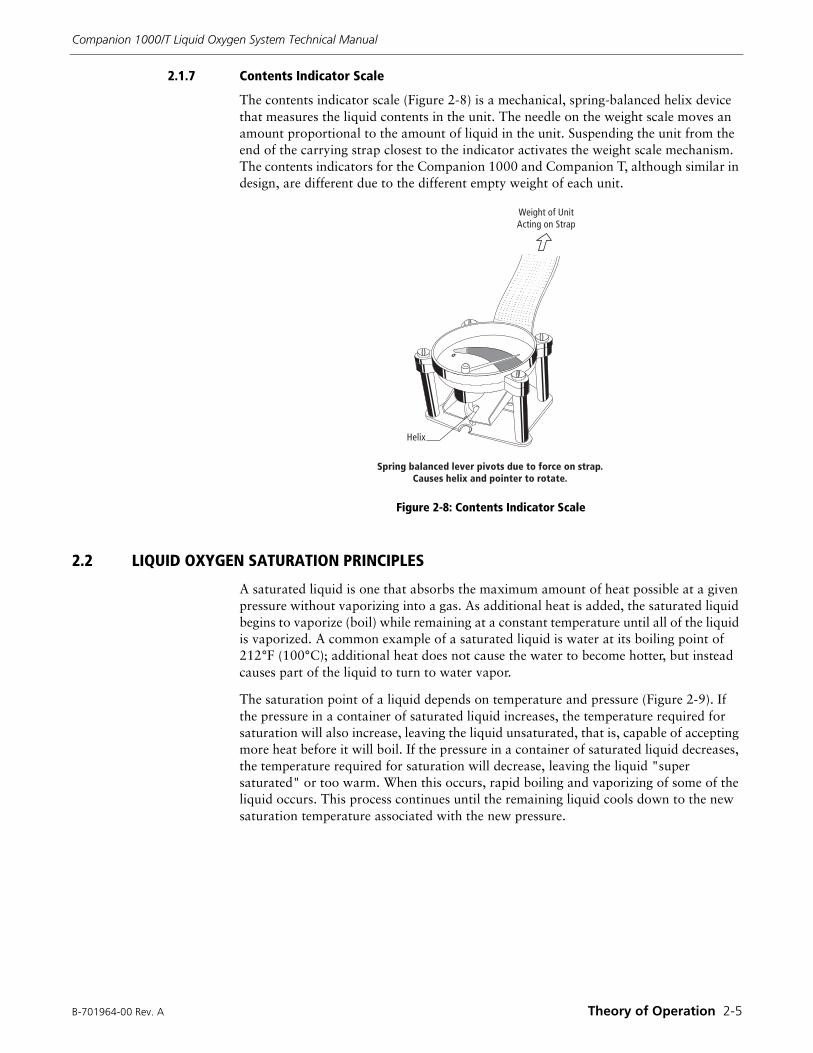
The primary and secondary relief valves are identical in design and function, differing only by their nominal setpoint (Figure 2-7). The primary relief valve sets the operating pressure at 22 psig (152 kPa). The secondary relief valve is a safety backup in the event that the primary relief valve does not maintain system pressure in the acceptable range. The secondary relief valve is set to open at a pressure of 30 psig (207 kPa).
The relief valve consists of a poppet with an elastomer seal and a spring. The poppet is normally closed by the force of the spring. When system pressure acting on one side of the poppet overcomes the spring force and atmospheric pressure acting on the opposite side, the poppet lifts off its seat and vents gas to atmosphere. The venting gas lowers the system pressure until equilibrium is established between the opening and closing forces on the poppet. If system pressure increases rapidly, the relief valve poppet opens a greater amount and vents additional gas to maintain the force equilibrium on the poppet.
Figure 2-7: Primary/Secondary Relief Valves
������ ����
���� ������
B-701964-00 Rev. A Theory of Operation 2-5
Companion 1000/T Liquid Oxygen System Technical Manual
2.1.7 Contents Indicator Scale
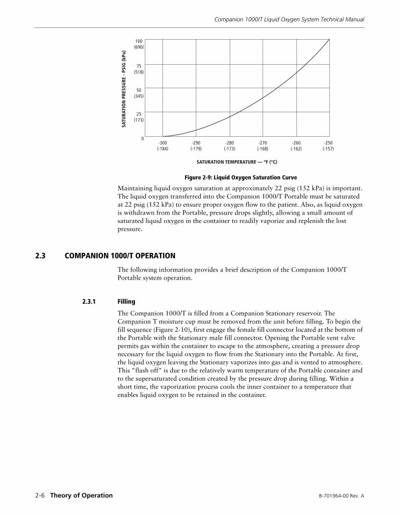
The contents indicator scale (Figure 2-8) is a mechanical, spring-balanced helix device that measures the liquid contents in the unit. The needle on the weight scale moves an amount proportional to the amount of liquid in the unit. Suspending the unit from the end of the carrying strap closest to the indicator activates the weight scale mechanism. The contents indicators for the Companion 1000 and Companion T, although similar in design, are different due to the different empty weight of each unit.
Figure 2-8: Contents Indicator Scale
2.2 LIQUID OXYGEN SATURATION PRINCIPLES
A saturated liquid is one that absorbs the maximum amount of heat possible at a given pressure without vaporizing into a gas. As additional heat is added, the saturated liquid begins to vaporize (boil) while remaining at a constant temperature until all of the liquid is vaporized. A common example of a saturated liquid is water at its boiling point of 212°F (100°C); additional heat does not cause the water to become hotter, but instead causes part of the liquid to turn to water vapor.
The saturation point of a liquid depends on temperature and pressure (Figure 2-9). If the pressure in a container of saturated liquid increases, the temperature required for saturation will also increase, leaving the liquid unsaturated, that is, capable of accepting more heat before it will boil. If the pressure in a container of saturated liquid decreases, the temperature required for saturation will decrease, leaving the liquid "super saturated" or too warm. When this occurs, rapid boiling and vaporizing of some of the liquid occurs. This process continues until the remaining liquid cools down to the new saturation temperature associated with the new pressure.
������ �� ������� � ����
�����
������ ������ � �� �� ��� ��� �� ���� �� ������������ ���� ��� ������� �� �������
Companion 1000/T Liquid Oxygen System Technical Manual
2-6 Theory of Operation B-701964-00 Rev. A
Figure 2-9: Liquid Oxygen Saturation Curve
Maintaining liquid oxygen saturation at approximately 22 psig (152 kPa) is important. The liquid oxygen transferred into the Companion 1000/T Portable must be saturated at 22 psig (152 kPa) to ensure proper oxygen flow to the patient. Also, as liquid oxygen is withdrawn from the Portable, pressure drops slightly, allowing a small amount of saturated liquid oxygen in the container to readily vaporize and replenish the lost pressure.
2.3 COMPANION 1000/T OPERATION
The following information provides a brief description of the Companion 1000/T Portable system operation.
2.3.1 Filling
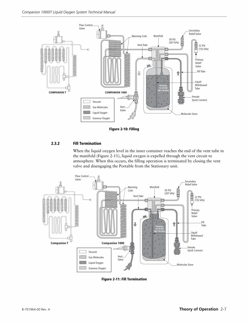
The Companion 1000/T is filled from a Companion Stationary reservoir. The Companion T moisture cup must be removed from the unit before filling. To begin the fill sequence (Figure 2-10), first engage the female fill connector located at the bottom of the Portable with the Stationary male fill connector. Opening the Portable vent valve permits gas within the container to escape to the atmosphere, creating a pressure drop necessary for the liquid oxygen to flow from the Stationary into the Portable. At first, the liquid oxygen leaving the Stationary vaporizes into gas and is vented to atmosphere. This "flash off" is due to the relatively warm temperature of the Portable container and to the supersaturated condition created by the pressure drop during filling. Within a short time, the vaporization process cools the inner container to a temperature that enables liquid oxygen to be retained in the container.
���
�����
��
����
��
����
��
����
�
�������������������
���
��
� ���
���
� ����
��
� ���
���
� ���
���
� ����
���
� ����
���������� ������� � �� ���
B-701964-00 Rev. A Theory of Operation 2-7
Companion 1000/T Liquid Oxygen System Technical Manual
Figure 2-10: Filling
2.3.2 Fill Termination
When the liquid oxygen level in the inner container reaches the end of the vent tube in the manifold (Figure 2-11), liquid oxygen is expelled through the vent circuit to atmosphere. When this occurs, the filling operation is terminated by closing the vent valve and disengaging the Portable from the Stationary unit.
Figure 2-11: Fill Termination
������
��� ������
� �� � ������
������ ������
�� ��������
���� �� � �
���� ����
��� ��
�������� � �� ����
!! "�#$%&! '"�(
"� ���� � ������
� ����
� �� �� �)���������
�����+� �' ������
��������
���� ���
����� ����
������ � ���
��������
��������� � ��������� ����
,- "�#$!-. '"�(
������
��� ������
� �� � ������
������ ������
��������� � ���������
�� ��������
���� ��� �
���� ����
��� ��� !"#$% & '!�(
"�������)� �� ����
%% !"#$*+% '!�(
!� ����)� ������
� ����
� �� �� �,���������
�����-� �' ������
������ " ���
��������
�� ���� ��� ���
���� ����
Companion 1000/T Liquid Oxygen System Technical Manual
2-8 Theory of Operation B-701964-00 Rev. A
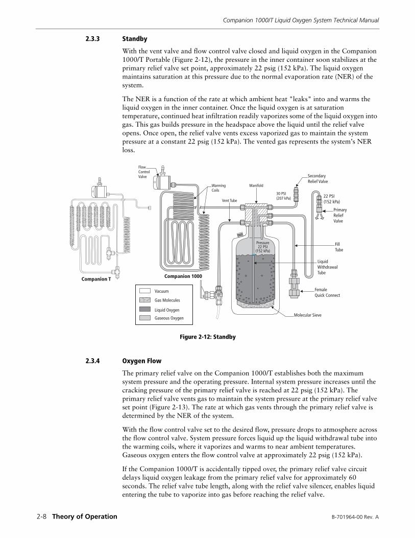
2.3.3 Standby
With the vent valve and flow control valve closed and liquid oxygen in the Companion 1000/T Portable (Figure 2-12), the pressure in the inner container soon stabilizes at the primary relief valve set point, approximately 22 psig (152 kPa). The liquid oxygen maintains saturation at this pressure due to the normal evaporation rate (NER) of the system.
The NER is a function of the rate at which ambient heat "leaks" into and warms the liquid oxygen in the inner container. Once the liquid oxygen is at saturation temperature, continued heat infiltration readily vaporizes some of the liquid oxygen into gas. This gas builds pressure in the headspace above the liquid until the relief valve opens. Once open, the relief valve vents excess vaporized gas to maintain the system pressure at a constant 22 psig (152 kPa). The vented gas represents the system’s NER loss.
Figure 2-12: Standby
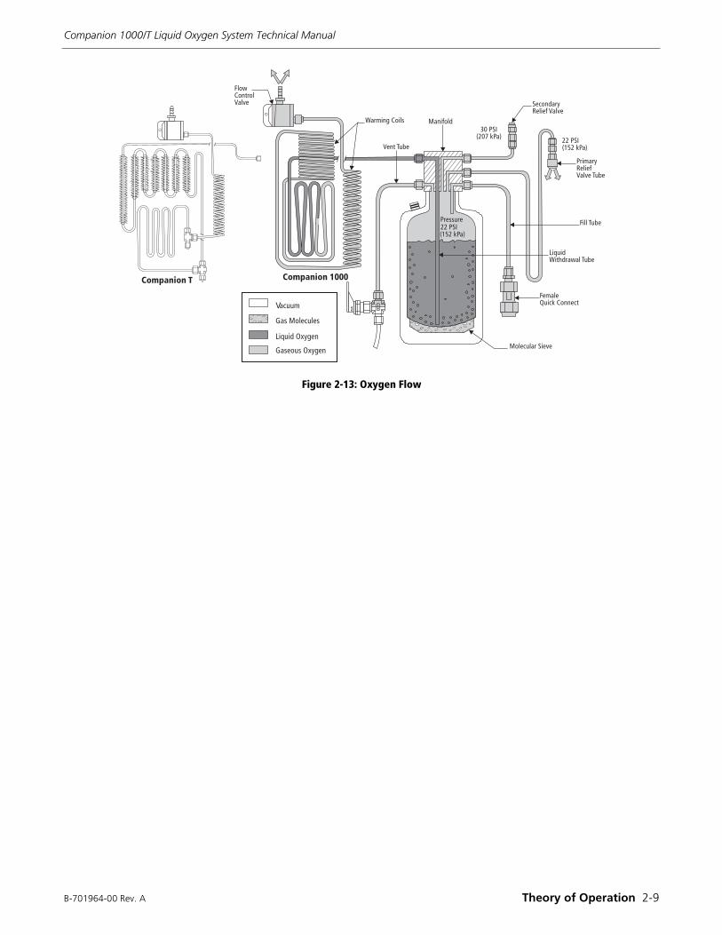
2.3.4 Oxygen Flow
The primary relief valve on the Companion 1000/T establishes both the maximum system pressure and the operating pressure. Internal system pressure increases until the cracking pressure of the primary relief valve is reached at 22 psig (152 kPa). The primary relief valve vents gas to maintain the system pressure at the primary relief valve set point (Figure 2-13). The rate at which gas vents through the primary relief valve is determined by the NER of the system.
With the flow control valve set to the desired flow, pressure drops to atmosphere across the flow control valve. System pressure forces liquid up the liquid withdrawal tube into the warming coils, where it vaporizes and warms to near ambient temperatures. Gaseous oxygen enters the flow control valve at approximately 22 psig (152 kPa).
If the Companion 1000/T is accidentally tipped over, the primary relief valve circuit delays liquid oxygen leakage from the primary relief valve for approximately 60 seconds. The relief valve tube length, along with the relief valve silencer, enables liquid entering the tube to vaporize into gas before reaching the relief valve.
Vacuum
Gas Molecules
Liquid Oxygen
Gaseous OxygenMolecular Sieve
Female Quick Connect
LiquidWithdrawalTube
FillTube
Pressure22 PSI
(152 kPa)
PrimaryReliefValve
22 PSI(152 kPa)
SecondaryRelief Valve
30 PSI(207 kPa)
Manifold
Vent Tube
WarmingCoils
FlowControlValve
Companion T Companion 1000
B-701964-00 Rev. A Theory of Operation 2-9
Companion 1000/T Liquid Oxygen System Technical Manual
Figure 2-13: Oxygen Flow
������� ���
� �� ���
�� ���� �� ������� ����
V�����
��� � �� �
����� !"#� �
��� �� !"#� �
$%������&
����' () ���
��)* ����
� �� ��#+ � ' ��&
�� ������� ����
������#+ � '��& ���
$� ���
����� ���, ��%� ���
$ �� -���� ��� ��
� ���� �� &
��������� � ���������
Companion 1000/T Liquid Oxygen System Technical Manual
2-10 Theory of Operation B-701964-00 Rev. A
B-701964-00 Rev. A Performance Verification 3-1
Section3PERFORMANCE VERIFICATION
This section provides testing information to verify Companion 1000/T performance for any of the following reasons:
• to determine the cause of operational problems.
• to check the unit's overall system operation after repairing or replacing a compo-nent.
• to verify the unit is operating within specifications.
3.1 EQUIPMENT REQUIRED
The following equipment is required to complete the performance verification tests in this section:
• Companion Stationary unit containing liquid oxygen saturated at relief valve pres-sure, 22 psig (152 kPa)
• portable test fixture (Figure 1-12)
• oxygen-compatible liquid leak detector (such as SNOOP)
• test flowmeters capable of accurately registering flows from 0 to 15 L/min (see Table 1-4)
• calibrated weight scale capable of accurately registering weight from 0 to 10 lb. (0 to 5 kg)
• 7/64-in. Allen (hex key) wrench
• an adjustable, 0 to 50 psig (0 to 345 kPa) source of gaseous oxygen with flexible 3/16-in. I.D. connection tubing
• a test pressure gauge with tubing adapter (Figure 1-13)
3.2 LEAKAGE TEST
Any amount of liquid oxygen leakage from the Companion 1000/T is unacceptable and calls for immediate removal from service. Minor gas leaks in connections and fittings will not affect system operation, provided they do not exceed the unit's NER.
Note: To perform the following tests, remove the side covers (Section 5.2.1, Service and Repair).
Note: Establish a calibration schedule for test equipment used in testing Companion 1000/T units. Follow Calibrating of Test Equipment (Section 1.11) to ensure accurate test results.
Note: Do not use the test flowmeter, test pressure gauge, or weight scale if they have been dropped or mishandled; recalibrate before placing them back into service.
Companion 1000/T Liquid Oxygen System Technical Manual
3-2 Performance Verification B-701964-00 Rev. A
Perform the following Liquid Leak Detector Test (Section 3.2.1) to determine if there are any substantial leaks. After performing this procedure, if you feel there is an unacceptable amount of leakage, perform the Pressure Hold Test (Section 3.2.2) to determine if the total leak rate is acceptable.
3.2.1 Liquid Leak Detector Test
PROCEDURE
1. Set the flow control valve to 0 L/min (off).
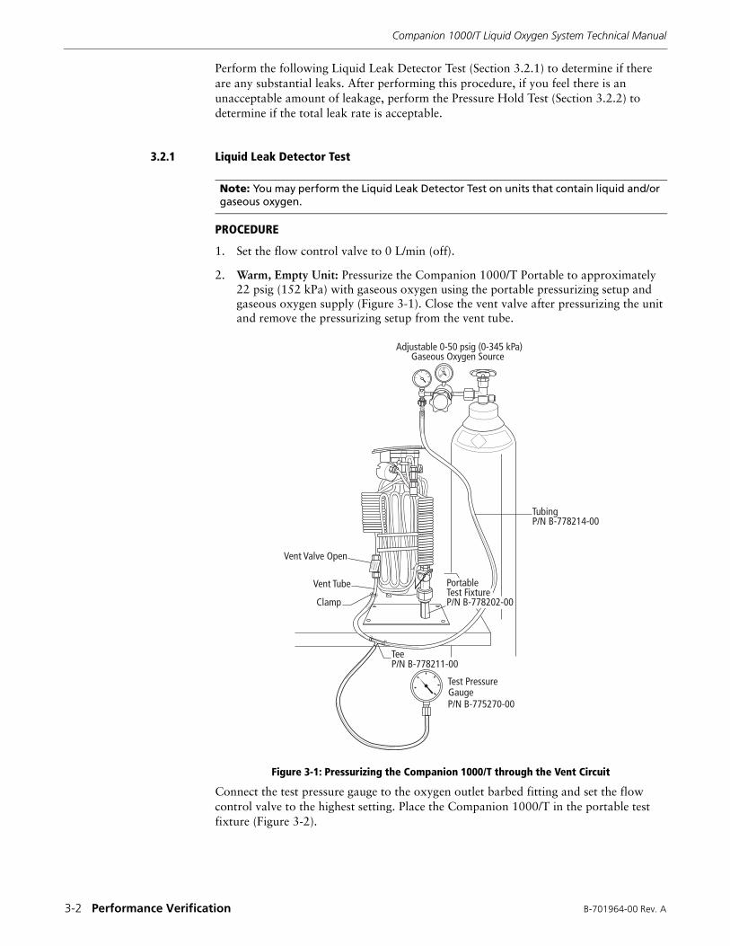
2. Warm, Empty Unit: Pressurize the Companion 1000/T Portable to approximately 22 psig (152 kPa) with gaseous oxygen using the portable pressurizing setup and gaseous oxygen supply (Figure 3-1). Close the vent valve after pressurizing the unit and remove the pressurizing setup from the vent tube.
Figure 3-1: Pressurizing the Companion 1000/T through the Vent Circuit
Connect the test pressure gauge to the oxygen outlet barbed fitting and set the flow control valve to the highest setting. Place the Companion 1000/T in the portable test fixture (Figure 3-2).
Note: You may perform the Liquid Leak Detector Test on units that contain liquid and/or gaseous oxygen.
Test PressureGaugeP/N B-775270-00
TubingP/N B-778214-00
Vent Tube
Vent Valve Open
Clamp
TeeP/N B-778211-00
Adjustable 0-50 psig (0-345 kPa)Gaseous Oxygen Source
PortableTest FixtureP/N B-778202-00
B-701964-00 Rev. A Performance Verification 3-3
Companion 1000/T Liquid Oxygen System Technical Manual
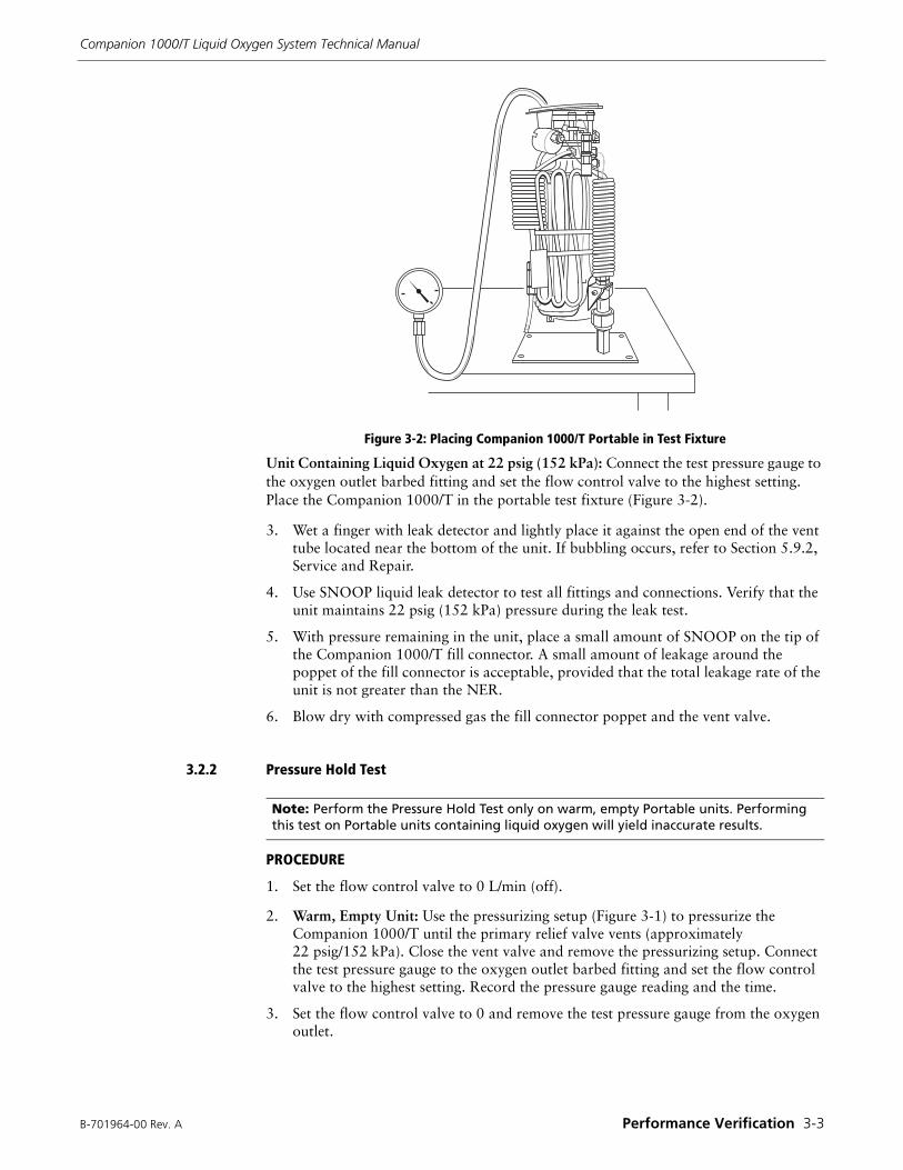
Figure 3-2: Placing Companion 1000/T Portable in Test Fixture
Unit Containing Liquid Oxygen at 22 psig (152 kPa): Connect the test pressure gauge to the oxygen outlet barbed fitting and set the flow control valve to the highest setting. Place the Companion 1000/T in the portable test fixture (Figure 3-2).
3. Wet a finger with leak detector and lightly place it against the open end of the vent tube located near the bottom of the unit. If bubbling occurs, refer to Section 5.9.2, Service and Repair.
4. Use SNOOP liquid leak detector to test all fittings and connections. Verify that the unit maintains 22 psig (152 kPa) pressure during the leak test.
5. With pressure remaining in the unit, place a small amount of SNOOP on the tip of the Companion 1000/T fill connector. A small amount of leakage around the poppet of the fill connector is acceptable, provided that the total leakage rate of the unit is not greater than the NER.
6. Blow dry with compressed gas the fill connector poppet and the vent valve.
3.2.2 Pressure Hold Test
PROCEDURE
1. Set the flow control valve to 0 L/min (off).
2. Warm, Empty Unit: Use the pressurizing setup (Figure 3-1) to pressurize the Companion 1000/T until the primary relief valve vents (approximately 22 psig/152 kPa). Close the vent valve and remove the pressurizing setup. Connect the test pressure gauge to the oxygen outlet barbed fitting and set the flow control valve to the highest setting. Record the pressure gauge reading and the time.
3. Set the flow control valve to 0 and remove the test pressure gauge from the oxygen outlet.
Note: Perform the Pressure Hold Test only on warm, empty Portable units. Performing this test on Portable units containing liquid oxygen will yield inaccurate results.
Companion 1000/T Liquid Oxygen System Technical Manual
3-4 Performance Verification B-701964-00 Rev. A
4. Do not disturb the Companion 1000/T for 8 to 9 hours. At the end of this evaluation period, verify the unit maintains at least 15 psig (104 kPa). Should the pressure be less than 15 psig (104 kPa), repressurize the unit to approximately 22 psig (152 kPa) and locate the leak by testing all components, fittings, and tubing with liquid leak detector. Make repairs as needed, taking care not to overtighten connections.
3.3 GASEOUS OXYGEN TESTS
Conduct the following tests on an empty unit that has warmed to room temperature.
3.3.1 Secondary Relief Valve Test
The secondary relief valve serves as a safety or backup to the primary relief valve. Under normal operating conditions, the secondary relief valve remains closed. The relief valve opens if the system pressure reaches 25 to 37 psig (172 to 255 kPa). This test uses gaseous oxygen to determine if the secondary relief valve opens within its acceptable range.
Refer to Figures 6-1, 6-2, 6-5 and 6-6 to identify parts with bold number references.
PROCEDURE
1. Connect the pressurizing setup to the Companion 1000/T (Figure 3-1).
2. Remove the silencer 6 from the primary relief valve 5.
3. Hold the primary relief valve closed while pressurizing the Portable. Increase the pressure until the secondary relief valve 1 opens (audible hiss) between 25 to 37 psig (172 to 255 kPa). If the secondary relief valve does not open within this range the first time, repeat the procedure. If it fails to open within the acceptable range the second time, replace the secondary relief valve (Section 5.8, Service and Repair).
3.3.2 Primary Relief Valve Test
The primary relief valve maintains system pressure at a preset value when the Companion 1000/T Portable contains liquid oxygen. This test uses only gaseous oxygen to determine if the primary relief valve opens within the acceptable range. Perform a primary relief valve function test when the Portable contains liquid oxygen.
Refer to Figure 6-5 to identify parts with bold number references.
PROCEDURE
1. Connect the pressurizing setup to the Companion 1000/T (Figure 3-1).
2. Place one drop of Snoop on the silencer 6. Slowly pressurize the unit with gaseous oxygen by adjusting the oxygen regulator.
3. Verify that the primary relief valve 5 opens (bubbles appear on silencer) at 20.5 to 24.0 psig (141 to 165 kPa). The primary relief valve vents through the silencer 6. If the valve does not open within the specified range, replace the primary relief valve (Section 5.7, Service and Repair).
NOTE: Do not release the primary relief valve poppet until pressure in the unit is reduced below 22 psig (152 kPa) by removing the pressurizing setup and opening the vent valve. Replace the primary relief valve silencer.
B-701964-00 Rev. A Performance Verification 3-5
Companion 1000/T Liquid Oxygen System Technical Manual
3.3.3 Vent Valve Test
When open, the vent valve creates a vent path to atmosphere from the Companion 1000/T container. This is required to commence filling. The vent valve must be leak-free when closed and it must allow an adequate flow of gas when open.
Refer to Figures 6-1, 6-2 and 6-7 for identification of parts with bold number references.
PROCEDURE
1. Perform steps 1 through 3 of the Leakage Test (Section 3.2.1).
2. Open the vent valve 7 and listen for a sudden exhaust of gaseous oxygen.
3.4 LIQUID OXYGEN TESTS
Conduct the following tests on units that contain liquid oxygen.
3.4.1 Contents Indicator Test
The contents indicator is a mechanical weight scale device that provides an approximate indication of the level of liquid oxygen in the Companion 1000/T inner container. Activate the contents indicator by holding the unit by the end of the carrying strap nearest the indicator.
Refer to Figure 6-3 to identify parts with bold number references.
PROCEDURE
1. Place the Companion 1000/T Portable on a table and hold it down while gently pulling up on the end of the carrying strap nearest the contents indicator. Verify that the indicator operates smoothly and without binding. Companion T - verify “Transport” is present on the indicator dial.
2. Suspend the unit by the end of the carrying strap nearest the contents indicator 2. Verify that the needle appears in the red EMPTY region at the end of the indicator window.
3. Fill the unit with liquid oxygen. Suspend the unit by the end of the carrying strap nearest the contents indicator. Verify that the needle is in the upper portion of the green FULL region.
3.4.2 Flow Control Test
The flow control valve on the Companion 1000/T is an adjustable, rotary, indexed valve that controls the delivery rate of gaseous oxygen from the Portable to the patient. The valve flow settings are calibrated at an inlet pressure of 22 psig (152 kPa). This test determines the acceptable flow ranges for the flow control valve.
NOTE: Disconnect the plastic buckle in the carrying strap before performing the following steps. The Companion 1000/T side covers must be in place when performing this test.
NOTE: If the unit does not pass the Contents Indicator Test, refer to Section 5.5, Service and Repair.
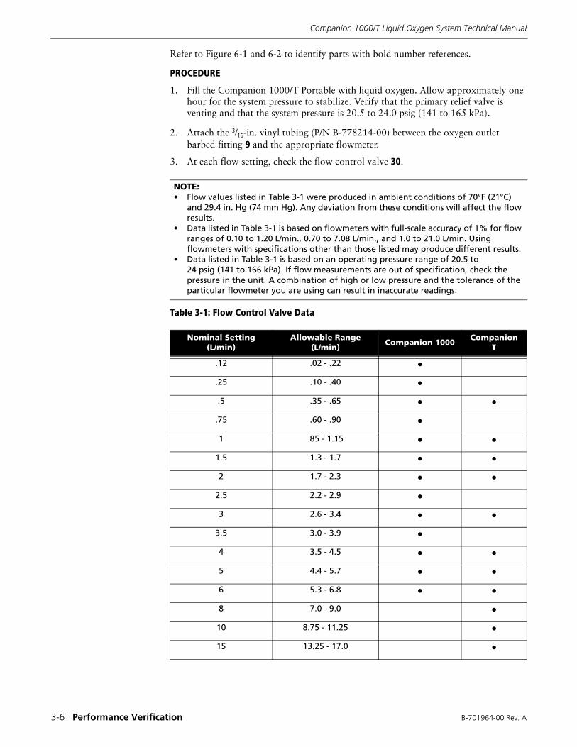
Companion 1000/T Liquid Oxygen System Technical Manual
3-6 Performance Verification B-701964-00 Rev. A
Refer to Figure 6-1 and 6-2 to identify parts with bold number references.
PROCEDURE
1. Fill the Companion 1000/T Portable with liquid oxygen. Allow approximately one hour for the system pressure to stabilize. Verify that the primary relief valve is venting and that the system pressure is 20.5 to 24.0 psig (141 to 165 kPa).
2. Attach the 3/16-in. vinyl tubing (P/N B-778214-00) between the oxygen outlet barbed fitting 9 and the appropriate flowmeter.
3. At each flow setting, check the flow control valve 30.
Table 3-1: Flow Control Valve Data
NOTE:• Flow values listed in Table 3-1 were produced in ambient conditions of 70°F (21°C)
and 29.4 in. Hg (74 mm Hg). Any deviation from these conditions will affect the flow results.
• Data listed in Table 3-1 is based on flowmeters with full-scale accuracy of 1% for flow ranges of 0.10 to 1.20 L/min., 0.70 to 7.08 L/min., and 1.0 to 21.0 L/min. Using flowmeters with specifications other than those listed may produce different results.
• Data listed in Table 3-1 is based on an operating pressure range of 20.5 to 24 psig (141 to 166 kPa). If flow measurements are out of specification, check the pressure in the unit. A combination of high or low pressure and the tolerance of the particular flowmeter you are using can result in inaccurate readings.
Nominal Setting(L/min)
Allowable Range(L/min)
Companion 1000Companion
T
.12 .02 - .22 �
.25 .10 - .40 �.5 .35 - .65 � �
.75 .60 - .90 �1 .85 - 1.15 � �
1.5 1.3 - 1.7 � �2 1.7 - 2.3 � �
2.5 2.2 - 2.9 �3 2.6 - 3.4 � �
3.5 3.0 - 3.9 �4 3.5 - 4.5 � �5 4.4 - 5.7 � �6 5.3 - 6.8 � �8 7.0 - 9.0 �10 8.75 - 11.25 �15 13.25 - 17.0 �
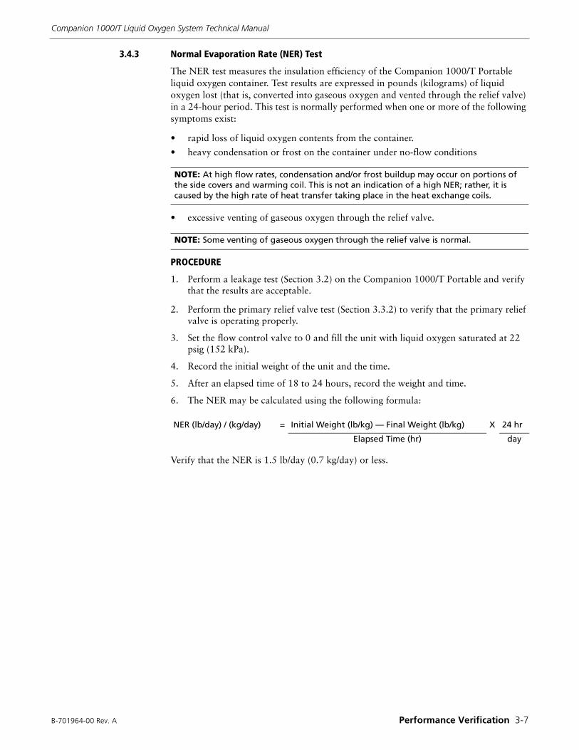
B-701964-00 Rev. A Performance Verification 3-7
Companion 1000/T Liquid Oxygen System Technical Manual
3.4.3 Normal Evaporation Rate (NER) Test
The NER test measures the insulation efficiency of the Companion 1000/T Portable liquid oxygen container. Test results are expressed in pounds (kilograms) of liquid oxygen lost (that is, converted into gaseous oxygen and vented through the relief valve) in a 24-hour period. This test is normally performed when one or more of the following symptoms exist:
• rapid loss of liquid oxygen contents from the container.
• heavy condensation or frost on the container under no-flow conditions
• excessive venting of gaseous oxygen through the relief valve.
PROCEDURE
1. Perform a leakage test (Section 3.2) on the Companion 1000/T Portable and verify that the results are acceptable.
2. Perform the primary relief valve test (Section 3.3.2) to verify that the primary relief valve is operating properly.
3. Set the flow control valve to 0 and fill the unit with liquid oxygen saturated at 22 psig (152 kPa).
4. Record the initial weight of the unit and the time.
5. After an elapsed time of 18 to 24 hours, record the weight and time.
6. The NER may be calculated using the following formula:
Verify that the NER is 1.5 lb/day (0.7 kg/day) or less.
NOTE: At high flow rates, condensation and/or frost buildup may occur on portions of the side covers and warming coil. This is not an indication of a high NER; rather, it is caused by the high rate of heat transfer taking place in the heat exchange coils.
NOTE: Some venting of gaseous oxygen through the relief valve is normal.
NER (lb/day) / (kg/day) = Initial Weight (lb/kg) — Final Weight (lb/kg) X 24 hr
Elapsed Time (hr) day

Companion 1000/T Liquid Oxygen System Technical Manual
3-8 Performance Verification B-701964-00 Rev. A
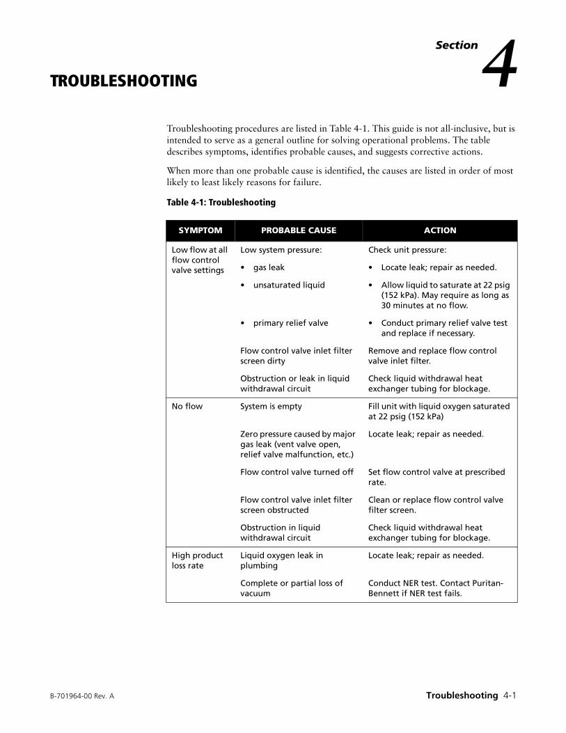
B-701964-00 Rev. A Troubleshooting 4-1
Section4TROUBLESHOOTING
Troubleshooting procedures are listed in Table 4-1. This guide is not all-inclusive, but is intended to serve as a general outline for solving operational problems. The table describes symptoms, identifies probable causes, and suggests corrective actions.
When more than one probable cause is identified, the causes are listed in order of most likely to least likely reasons for failure.
Table 4-1: Troubleshooting
SYMPTOM PROBABLE CAUSE ACTION
Low flow at all flow control valve settings
Low system pressure: Check unit pressure:
• gas leak • Locate leak; repair as needed.
• unsaturated liquid • Allow liquid to saturate at 22 psig (152 kPa). May require as long as 30 minutes at no flow.
• primary relief valve • Conduct primary relief valve test and replace if necessary.
Flow control valve inlet filter screen dirty
Remove and replace flow control valve inlet filter.
Obstruction or leak in liquid withdrawal circuit
Check liquid withdrawal heat exchanger tubing for blockage.
No flow System is empty Fill unit with liquid oxygen saturated at 22 psig (152 kPa)
Zero pressure caused by major gas leak (vent valve open, relief valve malfunction, etc.)
Locate leak; repair as needed.
Flow control valve turned off Set flow control valve at prescribed rate.
Flow control valve inlet filter screen obstructed
Clean or replace flow control valve filter screen.
Obstruction in liquid withdrawal circuit
Check liquid withdrawal heat exchanger tubing for blockage.
High product loss rate
Liquid oxygen leak in plumbing
Locate leak; repair as needed.
Complete or partial loss of vacuum
Conduct NER test. Contact Puritan-Bennett if NER test fails.
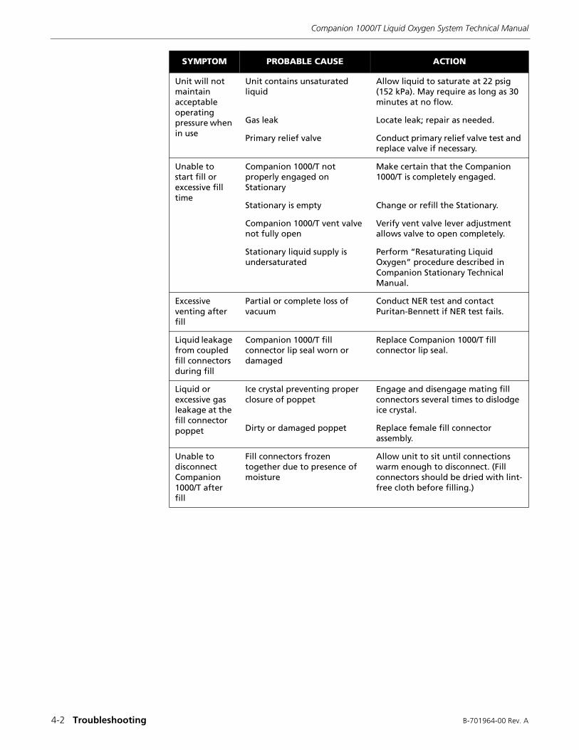
Companion 1000/T Liquid Oxygen System Technical Manual
4-2 Troubleshooting B-701964-00 Rev. A
Unit will not maintain acceptable operating pressure when in use
Unit contains unsaturated liquid
Allow liquid to saturate at 22 psig (152 kPa). May require as long as 30 minutes at no flow.
Gas leak Locate leak; repair as needed.
Primary relief valve Conduct primary relief valve test and replace valve if necessary.
Unable to start fill or excessive fill time
Companion 1000/T not properly engaged on Stationary
Make certain that the Companion 1000/T is completely engaged.
Stationary is empty Change or refill the Stationary.
Companion 1000/T vent valve not fully open
Verify vent valve lever adjustment allows valve to open completely.
Stationary liquid supply is undersaturated
Perform “Resaturating Liquid Oxygen” procedure described in Companion Stationary Technical Manual.
Excessive venting after fill
Partial or complete loss of vacuum
Conduct NER test and contact Puritan-Bennett if NER test fails.
Liquid leakage from coupled fill connectors during fill
Companion 1000/T fill connector lip seal worn or damaged
Replace Companion 1000/T fill connector lip seal.
Liquid or excessive gas leakage at the fill connector poppet
Ice crystal preventing proper closure of poppet
Engage and disengage mating fill connectors several times to dislodge ice crystal.
Dirty or damaged poppet Replace female fill connector assembly.
Unable to disconnect Companion 1000/T after fill
Fill connectors frozen together due to presence of moisture
Allow unit to sit until connections warm enough to disconnect. (Fill connectors should be dried with lint-free cloth before filling.)
SYMPTOM PROBABLE CAUSE ACTION

B-701964-00 Rev. A Service and Repair 5-1
Section5SERVICE AND REPAIR
This section provides procedures for servicing the individual components of the Companion 1000/T Portable. Where applicable, instructions are included for removal, disassembly, operational check, cleaning, inspection, adjustment, reassembly, and installation.
After removing a component, visually inspect it for damage or any indication that the part should be replaced. Unless otherwise specified, replace as needed with a new part. Refer to the exploded view illustrations and the Companion 1000/T parts list in Section 6.
The Companion 1000/T can be emptied by setting the flow control at its highest setting and allowing the unit to run until all liquid oxygen is depleted. When the liquid oxygen is depleted, you can leave a flow set on the control while working on the unit to provide continuous system venting.
5.1 PRESSURE FITTINGS AND CONNECTIONS
The Companion 1000/T Portable uses two types of fittings: compression tube fittings and National Pipe Tapered (NPT) fittings. Proper make-up of these pressure fittings is essential to leak-free operation.
WARNING
Personal injury can occur from the uncontrolled release of pressurized gaseous and liquid oxygen. Empty liquid oxygen contents and vent system pressure before servicing.
WARNING
Concentrated oxygen. Increased risk of fire. Place unit in a well-ventilated area away from sources of ignition when setting a flow to empty unit.
WARNING
Injury to eyes from flying objects possible. Wear eye protection when servicing the Portable.
NOTE: After making repairs, always verify proper system operation by performing the functional tests in Section 3.
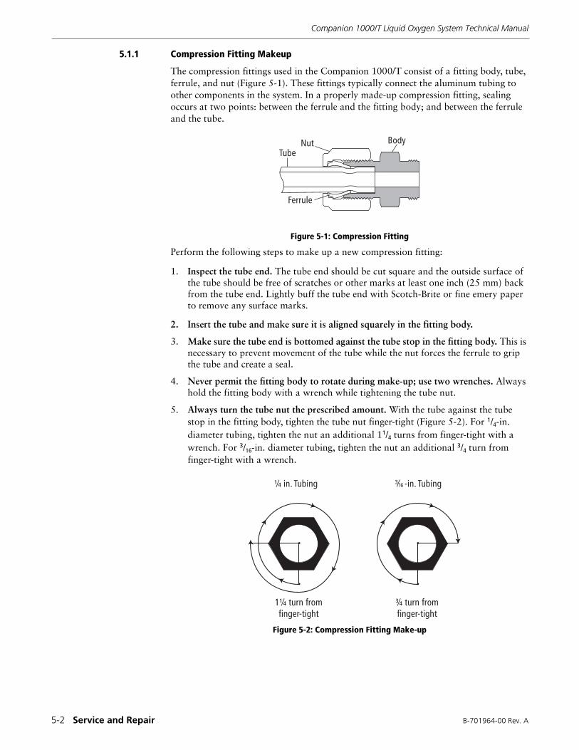
Companion 1000/T Liquid Oxygen System Technical Manual
5-2 Service and Repair B-701964-00 Rev. A
5.1.1 Compression Fitting Makeup
The compression fittings used in the Companion 1000/T consist of a fitting body, tube, ferrule, and nut (Figure 5-1). These fittings typically connect the aluminum tubing to other components in the system. In a properly made-up compression fitting, sealing occurs at two points: between the ferrule and the fitting body; and between the ferrule and the tube.
Figure 5-1: Compression Fitting
Perform the following steps to make up a new compression fitting:
1. Inspect the tube end. The tube end should be cut square and the outside surface of the tube should be free of scratches or other marks at least one inch (25 mm) back from the tube end. Lightly buff the tube end with Scotch-Brite or fine emery paper to remove any surface marks.
2. Insert the tube and make sure it is aligned squarely in the fitting body.
3. Make sure the tube end is bottomed against the tube stop in the fitting body. This is necessary to prevent movement of the tube while the nut forces the ferrule to grip the tube and create a seal.
4. Never permit the fitting body to rotate during make-up; use two wrenches. Always hold the fitting body with a wrench while tightening the tube nut.
5. Always turn the tube nut the prescribed amount. With the tube against the tube stop in the fitting body, tighten the tube nut finger-tight (Figure 5-2). For 1/4-in. diameter tubing, tighten the nut an additional 11/4 turns from finger-tight with a wrench. For 3/16-in. diameter tubing, tighten the nut an additional 3/4 turn from finger-tight with a wrench.
Figure 5-2: Compression Fitting Make-up
�������
�������
��
� ��� ������
� ��� �� �����������
� ��� �� �����������
���� ������
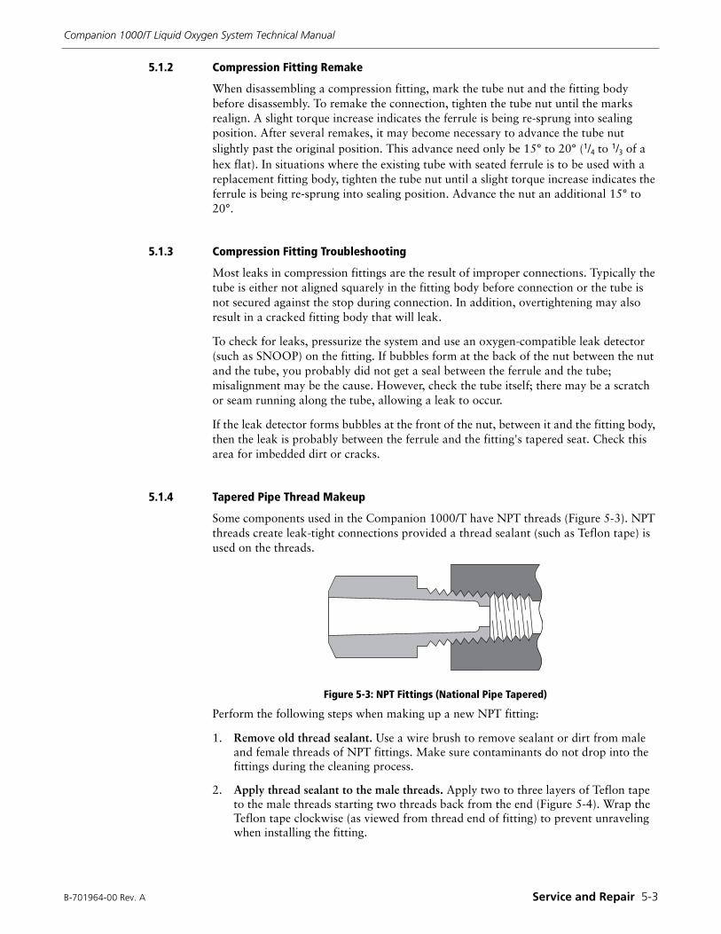
B-701964-00 Rev. A Service and Repair 5-3
Companion 1000/T Liquid Oxygen System Technical Manual
5.1.2 Compression Fitting Remake
When disassembling a compression fitting, mark the tube nut and the fitting body before disassembly. To remake the connection, tighten the tube nut until the marks realign. A slight torque increase indicates the ferrule is being re-sprung into sealing position. After several remakes, it may become necessary to advance the tube nut slightly past the original position. This advance need only be 15° to 20° (1/4 to 1/3 of a hex flat). In situations where the existing tube with seated ferrule is to be used with a replacement fitting body, tighten the tube nut until a slight torque increase indicates the ferrule is being re-sprung into sealing position. Advance the nut an additional 15° to 20°.
5.1.3 Compression Fitting Troubleshooting
Most leaks in compression fittings are the result of improper connections. Typically the tube is either not aligned squarely in the fitting body before connection or the tube is not secured against the stop during connection. In addition, overtightening may also result in a cracked fitting body that will leak.
To check for leaks, pressurize the system and use an oxygen-compatible leak detector (such as SNOOP) on the fitting. If bubbles form at the back of the nut between the nut and the tube, you probably did not get a seal between the ferrule and the tube; misalignment may be the cause. However, check the tube itself; there may be a scratch or seam running along the tube, allowing a leak to occur.
If the leak detector forms bubbles at the front of the nut, between it and the fitting body, then the leak is probably between the ferrule and the fitting's tapered seat. Check this area for imbedded dirt or cracks.
5.1.4 Tapered Pipe Thread Makeup
Some components used in the Companion 1000/T have NPT threads (Figure 5-3). NPT threads create leak-tight connections provided a thread sealant (such as Teflon tape) is used on the threads.
Figure 5-3: NPT Fittings (National Pipe Tapered)
Perform the following steps when making up a new NPT fitting:
1. Remove old thread sealant. Use a wire brush to remove sealant or dirt from male and female threads of NPT fittings. Make sure contaminants do not drop into the fittings during the cleaning process.
2. Apply thread sealant to the male threads. Apply two to three layers of Teflon tape to the male threads starting two threads back from the end (Figure 5-4). Wrap the Teflon tape clockwise (as viewed from thread end of fitting) to prevent unraveling when installing the fitting.
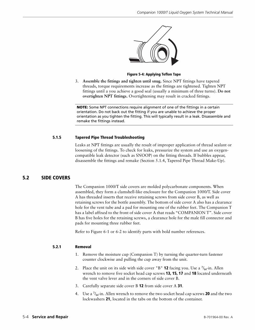
Companion 1000/T Liquid Oxygen System Technical Manual
5-4 Service and Repair B-701964-00 Rev. A
Figure 5-4: Applying Teflon Tape
3. Assemble the fittings and tighten until snug. Since NPT fittings have tapered threads, torque requirements increase as the fittings are tightened. Tighten NPT fittings until a you achieve a good seal (usually a minimum of three turns). Do not overtighten NPT fittings. Overtightening may result in cracked fittings.
5.1.5 Tapered Pipe Thread Troubleshooting
Leaks at NPT fittings are usually the result of improper application of thread sealant or loosening of the fittings. To check for leaks, pressurize the system and use an oxygen-compatible leak detector (such as SNOOP) on the fitting threads. If bubbles appear, disassemble the fittings and remake (Section 5.1.4, Tapered Pipe Thread Make-Up).
5.2 SIDE COVERS
The Companion 1000/T side covers are molded polycarbonate components. When assembled, they form a clamshell-like enclosure for the Companion 1000/T. Side cover A has threaded inserts that receive retaining screws from side cover B, as well as retaining screws for the bottle assembly. The bottom of side cover A also has a clearance hole for the vent tube and a pad for mounting one of the rubber feet. The Companion T has a label affixed to the front of side cover A that reads “COMPANION T”. Side cover B has five holes for the retaining screws, a clearance hole for the male fill connector and pads for mounting three rubber feet.
Refer to Figure 6-1 or 6-2 to identify parts with bold number references.
5.2.1 Removal
1. Remove the moisture cup (Companion T) by turning the quarter-turn fastener counter clockwise and pulling the cup away from the unit.
2. Place the unit on its side with side cover "B" 12 facing you. Use a 7/64-in. Allen wrench to remove five socket head cap screws 13, 15, 17 and 18 located underneath the vent valve lever and in the corners of side cover B.
3. Carefully separate side cover B 12 from side cover A 31.
4. Use a 7/64-in. Allen wrench to remove the two socket head cap screws 20 and the two lockwashers 21, located in the tabs on the bottom of the container.
NOTE: Some NPT connections require alignment of one of the fittings in a certain orientation. Do not back out the fitting if you are unable to achieve the proper orientation as you tighten the fitting. This will typically result in a leak. Disassemble and remake the fittings instead.
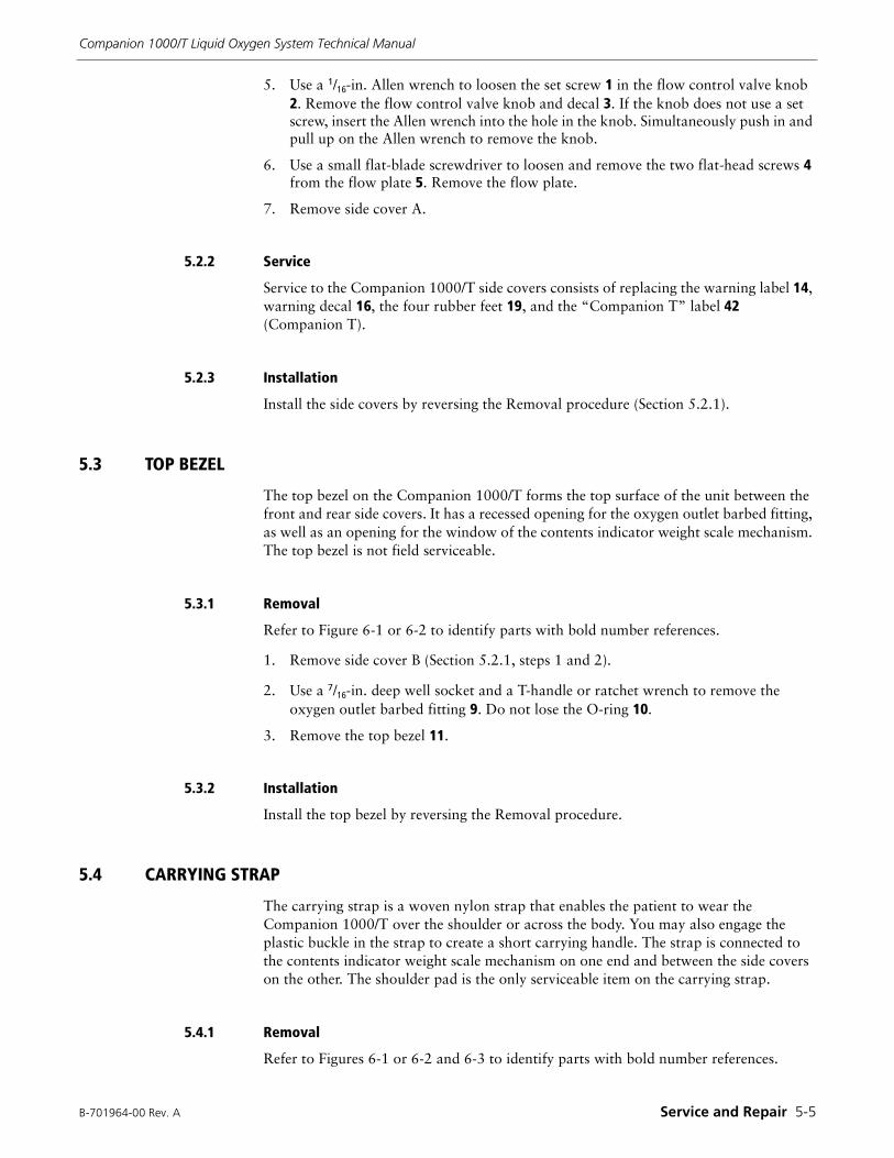
B-701964-00 Rev. A Service and Repair 5-5
Companion 1000/T Liquid Oxygen System Technical Manual
5. Use a 1/16-in. Allen wrench to loosen the set screw 1 in the flow control valve knob 2. Remove the flow control valve knob and decal 3. If the knob does not use a set screw, insert the Allen wrench into the hole in the knob. Simultaneously push in and pull up on the Allen wrench to remove the knob.
6. Use a small flat-blade screwdriver to loosen and remove the two flat-head screws 4 from the flow plate 5. Remove the flow plate.
7. Remove side cover A.
5.2.2 Service
Service to the Companion 1000/T side covers consists of replacing the warning label 14, warning decal 16, the four rubber feet 19, and the “Companion T” label 42 (Companion T).
5.2.3 Installation
Install the side covers by reversing the Removal procedure (Section 5.2.1).
5.3 TOP BEZEL
The top bezel on the Companion 1000/T forms the top surface of the unit between the front and rear side covers. It has a recessed opening for the oxygen outlet barbed fitting, as well as an opening for the window of the contents indicator weight scale mechanism. The top bezel is not field serviceable.
5.3.1 Removal
Refer to Figure 6-1 or 6-2 to identify parts with bold number references.
1. Remove side cover B (Section 5.2.1, steps 1 and 2).
2. Use a 7/16-in. deep well socket and a T-handle or ratchet wrench to remove the oxygen outlet barbed fitting 9. Do not lose the O-ring 10.
3. Remove the top bezel 11.
5.3.2 Installation
Install the top bezel by reversing the Removal procedure.
5.4 CARRYING STRAP
The carrying strap is a woven nylon strap that enables the patient to wear the Companion 1000/T over the shoulder or across the body. You may also engage the plastic buckle in the strap to create a short carrying handle. The strap is connected to the contents indicator weight scale mechanism on one end and between the side covers on the other. The shoulder pad is the only serviceable item on the carrying strap.
5.4.1 Removal
Refer to Figures 6-1 or 6-2 and 6-3 to identify parts with bold number references.
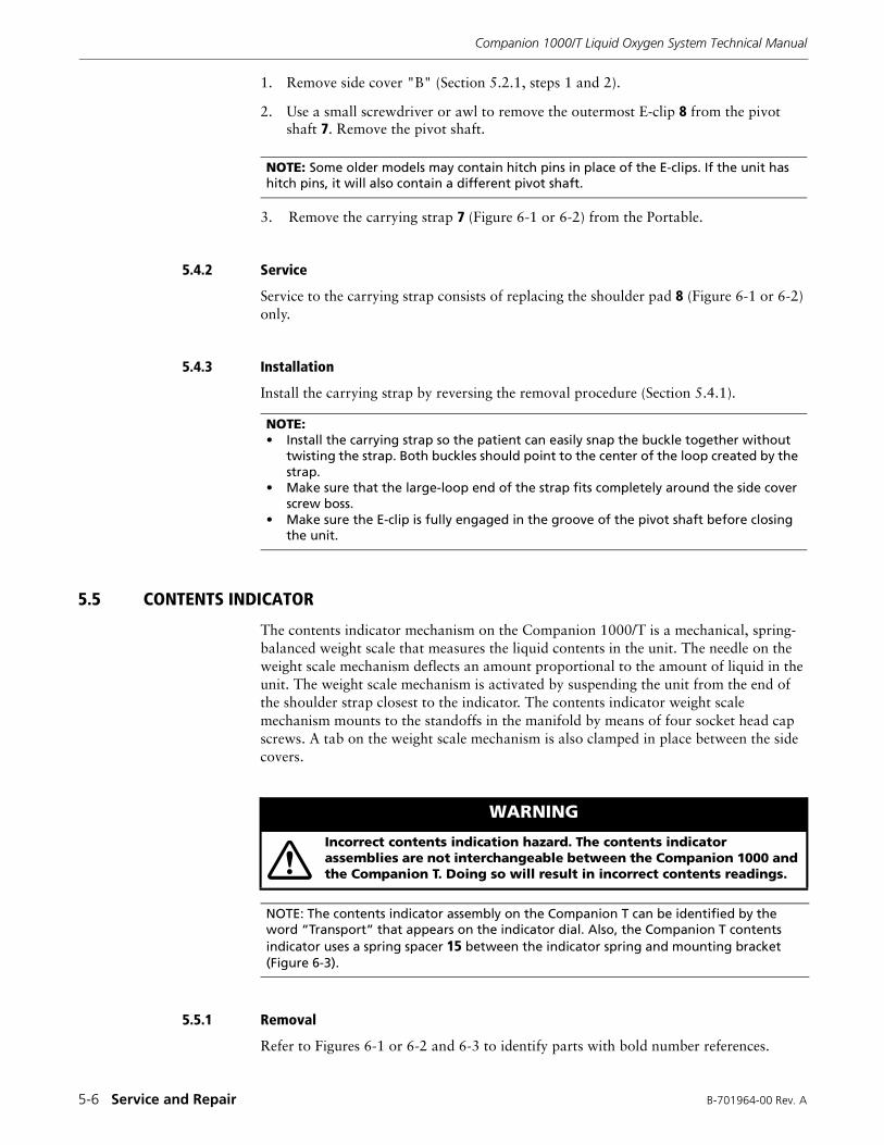
Companion 1000/T Liquid Oxygen System Technical Manual
5-6 Service and Repair B-701964-00 Rev. A
1. Remove side cover "B" (Section 5.2.1, steps 1 and 2).
2. Use a small screwdriver or awl to remove the outermost E-clip 8 from the pivot shaft 7. Remove the pivot shaft.
3. Remove the carrying strap 7 (Figure 6-1 or 6-2) from the Portable.
5.4.2 Service
Service to the carrying strap consists of replacing the shoulder pad 8 (Figure 6-1 or 6-2) only.
5.4.3 Installation
Install the carrying strap by reversing the removal procedure (Section 5.4.1).
5.5 CONTENTS INDICATOR
The contents indicator mechanism on the Companion 1000/T is a mechanical, spring-balanced weight scale that measures the liquid contents in the unit. The needle on the weight scale mechanism deflects an amount proportional to the amount of liquid in the unit. The weight scale mechanism is activated by suspending the unit from the end of the shoulder strap closest to the indicator. The contents indicator weight scale mechanism mounts to the standoffs in the manifold by means of four socket head cap screws. A tab on the weight scale mechanism is also clamped in place between the side covers.
5.5.1 Removal
Refer to Figures 6-1 or 6-2 and 6-3 to identify parts with bold number references.
NOTE: Some older models may contain hitch pins in place of the E-clips. If the unit has hitch pins, it will also contain a different pivot shaft.
NOTE: • Install the carrying strap so the patient can easily snap the buckle together without
twisting the strap. Both buckles should point to the center of the loop created by the strap.
• Make sure that the large-loop end of the strap fits completely around the side cover screw boss.
• Make sure the E-clip is fully engaged in the groove of the pivot shaft before closing the unit.
WARNING
Incorrect contents indication hazard. The contents indicator assemblies are not interchangeable between the Companion 1000 and the Companion T. Doing so will result in incorrect contents readings.
NOTE: The contents indicator assembly on the Companion T can be identified by the word “Transport” that appears on the indicator dial. Also, the Companion T contents indicator uses a spring spacer 15 between the indicator spring and mounting bracket (Figure 6-3).
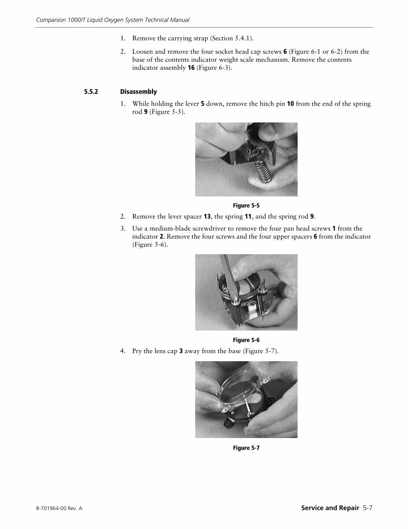
B-701964-00 Rev. A Service and Repair 5-7
Companion 1000/T Liquid Oxygen System Technical Manual
1. Remove the carrying strap (Section 5.4.1).
2. Loosen and remove the four socket head cap screws 6 (Figure 6-1 or 6-2) from the base of the contents indicator weight scale mechanism. Remove the contents indicator assembly 16 (Figure 6-3).
5.5.2 Disassembly
1. While holding the lever 5 down, remove the hitch pin 10 from the end of the spring rod 9 (Figure 5-5).
Figure 5-5
2. Remove the lever spacer 13, the spring 11, and the spring rod 9.
3. Use a medium-blade screwdriver to remove the four pan head screws 1 from the indicator 2. Remove the four screws and the four upper spacers 6 from the indicator (Figure 5-6).
Figure 5-6
4. Pry the lens cap 3 away from the base (Figure 5-7).
Figure 5-7
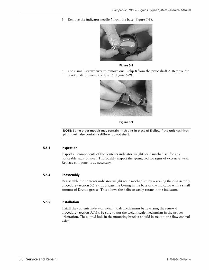
Companion 1000/T Liquid Oxygen System Technical Manual
5-8 Service and Repair B-701964-00 Rev. A
5. Remove the indicator needle 4 from the base (Figure 5-8).
Figure 5-8
6. Use a small screwdriver to remove one E-clip 8 from the pivot shaft 7. Remove the pivot shaft. Remove the lever 5 (Figure 5-9).
Figure 5-9
5.5.3 Inspection
Inspect all components of the contents indicator weight scale mechanism for any noticeable signs of wear. Thoroughly inspect the spring rod for signs of excessive wear. Replace components as necessary.
5.5.4 Reassembly
Reassemble the contents indicator weight scale mechanism by reversing the disassembly procedure (Section 5.5.2). Lubricate the O-ring in the base of the indicator with a small amount of Krytox grease. This allows the helix to easily rotate in the indicator.
5.5.5 Installation
Install the contents indicator weight scale mechanism by reversing the removal procedure (Section 5.5.1). Be sure to put the weight scale mechanism in the proper orientation. The slotted hole in the mounting bracket should be next to the flow control valve.
NOTE: Some older models may contain hitch pins in place of E-clips. If the unit has hitch pins, it will also contain a different pivot shaft.
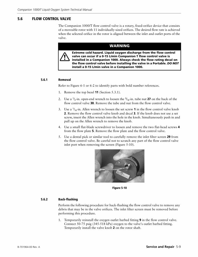
B-701964-00 Rev. A Service and Repair 5-9
Companion 1000/T Liquid Oxygen System Technical Manual
5.6 FLOW CONTROL VALVE
The Companion 1000/T flow control valve is a rotary, fixed-orifice device that consists of a moveable rotor with 11 individually-sized orifices. The desired flow rate is achieved when the selected orifice in the rotor is aligned between the inlet and outlet ports of the valve.
5.6.1 Removal
Refer to Figure 6-1 or 6-2 to identify parts with bold number references.
1. Remove the top bezel 11 (Section 5.3.1).
2. Use a 1/2-in. open-end wrench to loosen the 3/16-in. tube nut 27 on the back of the flow control valve 30. Remove the tube and nut from the flow control valve.
3. Use a 1/16-in. Allen wrench to loosen the set screw 1 in the flow control valve knob 2. Remove the flow control valve knob and decal 3. If the knob does not use a set screw, insert the Allen wrench into the hole in the knob. Simultaneously push in and pull up on the Allen wrench to remove the knob.
4. Use a small flat-blade screwdriver to loosen and remove the two flat-head screws 4 from the flow plate 5. Remove the flow plate and the flow control valve.
5. Use a dental pick or similar tool to carefully remove the inlet filter screen 29 from the flow control valve. Be careful not to scratch any part of the flow control valve inlet port when removing the screen (Figure 5-10).
Figure 5-10
5.6.2 Back-flushing
Perform the following procedure for back-flushing the flow control valve to remove any debris that may be in the valve orifices. The inlet filter screen must be removed before performing this procedure.
1. Temporarily reinstall the oxygen outlet barbed fitting 9 in the flow control valve. Connect 50-75 psig (345-518 kPa) oxygen to the valve’s outlet barbed fitting. Temporarily install the valve knob 2 on the rotor shaft.
WARNING
Extreme cold hazard. Liquid oxygen discharge from the flow control valve can occur if a 0-15 L/min Companion T flow control valve is installed in a Companion 1000. Always check the flow rating decal on the flow control valve before installing the valve in a Portable. DO NOT install a 0-15 L/min valve in a Companion 1000.
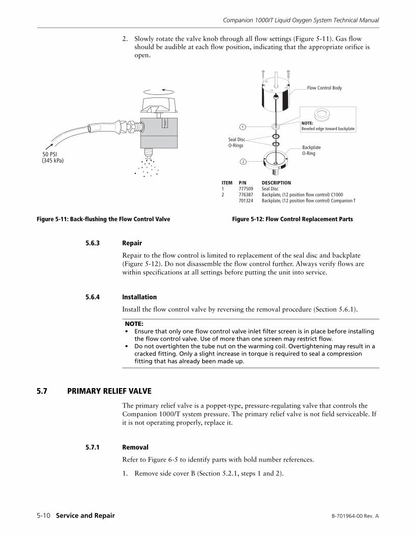
Companion 1000/T Liquid Oxygen System Technical Manual
5-10 Service and Repair B-701964-00 Rev. A
2. Slowly rotate the valve knob through all flow settings (Figure 5-11). Gas flow should be audible at each flow position, indicating that the appropriate orifice is open.
Figure 5-11: Back-flushing the Flow Control Valve Figure 5-12: Flow Control Replacement Parts
5.6.3 Repair
Repair to the flow control is limited to replacement of the seal disc and backplate (Figure 5-12). Do not disassemble the flow control further. Always verify flows are within specifications at all settings before putting the unit into service.
5.6.4 Installation
Install the flow control valve by reversing the removal procedure (Section 5.6.1).
5.7 PRIMARY RELIEF VALVE
The primary relief valve is a poppet-type, pressure-regulating valve that controls the Companion 1000/T system pressure. The primary relief valve is not field serviceable. If it is not operating properly, replace it.
5.7.1 Removal
Refer to Figure 6-5 to identify parts with bold number references.
1. Remove side cover B (Section 5.2.1, steps 1 and 2).
�� ������� ��
NOTE:Beveled edge toward backplate
BackplateO-Ring
Flow Control Body
Seal DiscO-Rings
1
2
ITEM P/N DESCRIPTION1 777509 Seal Disc2 776387 Backplate, (12 position flow control) C1000
701324 Backplate, (12 position flow control) Companion T
NOTE: • Ensure that only one flow control valve inlet filter screen is in place before installing
the flow control valve. Use of more than one screen may restrict flow.• Do not overtighten the tube nut on the warming coil. Overtightening may result in a
cracked fitting. Only a slight increase in torque is required to seal a compression fitting that has already been made up.

(Blank Page)
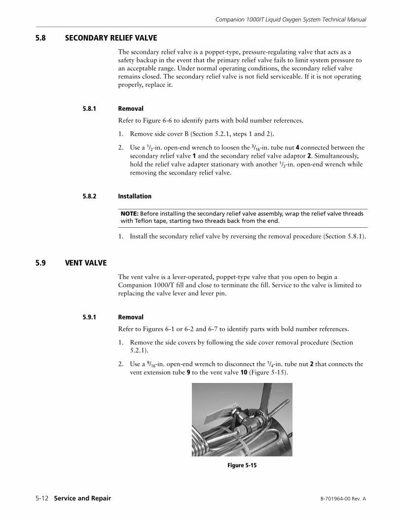
Companion 1000/T Liquid Oxygen System Technical Manual
5-12 Service and Repair B-701964-00 Rev. A
5.8 SECONDARY RELIEF VALVE
The secondary relief valve is a poppet-type, pressure-regulating valve that acts as a safety backup in the event that the primary relief valve fails to limit system pressure to an acceptable range. Under normal operating conditions, the secondary relief valve remains closed. The secondary relief valve is not field serviceable. If it is not operating properly, replace it.
5.8.1 Removal
Refer to Figure 6-6 to identify parts with bold number references.
1. Remove side cover B (Section 5.2.1, steps 1 and 2).
2. Use a 1/2-in. open-end wrench to loosen the 3/16-in. tube nut 4 connected between the secondary relief valve 1 and the secondary relief valve adaptor 2. Simultaneously, hold the relief valve adapter stationary with another 1/2-in. open-end wrench while removing the secondary relief valve.
5.8.2 Installation
1. Install the secondary relief valve by reversing the removal procedure (Section 5.8.1).
5.9 VENT VALVE
The vent valve is a lever-operated, poppet-type valve that you open to begin a Companion 1000/T fill and close to terminate the fill. Service to the valve is limited to replacing the valve lever and lever pin.
5.9.1 Removal
Refer to Figures 6-1 or 6-2 and 6-7 to identify parts with bold number references.
1. Remove the side covers by following the side cover removal procedure (Section 5.2.1).
2. Use a 9/16-in. open-end wrench to disconnect the 1/4-in. tube nut 2 that connects the vent extension tube 9 to the vent valve 10 (Figure 5-15).
Figure 5-15
NOTE: Before installing the secondary relief valve assembly, wrap the relief valve threads with Teflon tape, starting two threads back from the end.
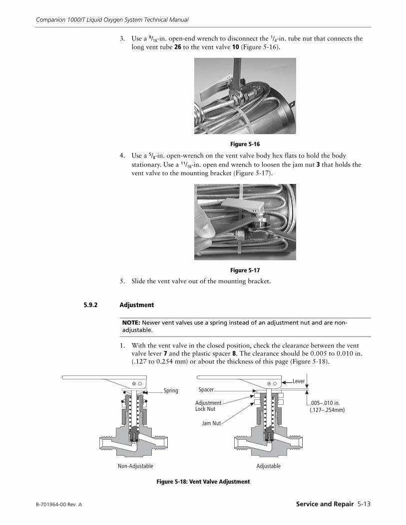
B-701964-00 Rev. A Service and Repair 5-13
Companion 1000/T Liquid Oxygen System Technical Manual
3. Use a 9/16-in. open-end wrench to disconnect the 1/4-in. tube nut that connects the long vent tube 26 to the vent valve 10 (Figure 5-16).
Figure 5-16
4. Use a 5/8-in. open-wrench on the vent valve body hex flats to hold the body stationary. Use a 11/16-in. open end wrench to loosen the jam nut 3 that holds the vent valve to the mounting bracket (Figure 5-17).
Figure 5-17
5. Slide the vent valve out of the mounting bracket.
5.9.2 Adjustment
1. With the vent valve in the closed position, check the clearance between the vent valve lever 7 and the plastic spacer 8. The clearance should be 0.005 to 0.010 in. (.127 to 0.254 mm) or about the thickness of this page (Figure 5-18).
Figure 5-18: Vent Valve Adjustment
NOTE: Newer vent valves use a spring instead of an adjustment nut and are non-adjustable.
����������� ���������
�����
������������� ��
��� ��
���
��������� ������ !�� �"��#
�����$
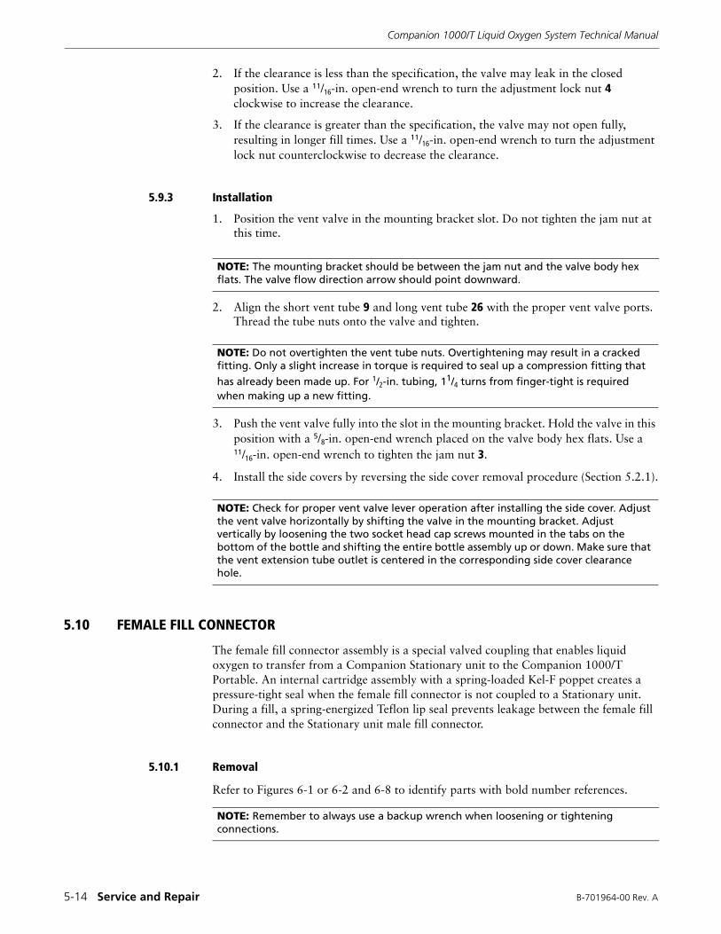
Companion 1000/T Liquid Oxygen System Technical Manual
5-14 Service and Repair B-701964-00 Rev. A
2. If the clearance is less than the specification, the valve may leak in the closed position. Use a 11/16-in. open-end wrench to turn the adjustment lock nut 4 clockwise to increase the clearance.
3. If the clearance is greater than the specification, the valve may not open fully, resulting in longer fill times. Use a 11/16-in. open-end wrench to turn the adjustment lock nut counterclockwise to decrease the clearance.
5.9.3 Installation
1. Position the vent valve in the mounting bracket slot. Do not tighten the jam nut at this time.
2. Align the short vent tube 9 and long vent tube 26 with the proper vent valve ports. Thread the tube nuts onto the valve and tighten.
3. Push the vent valve fully into the slot in the mounting bracket. Hold the valve in this position with a 5/8-in. open-end wrench placed on the valve body hex flats. Use a 11/16-in. open-end wrench to tighten the jam nut 3.
4. Install the side covers by reversing the side cover removal procedure (Section 5.2.1).
5.10 FEMALE FILL CONNECTOR
The female fill connector assembly is a special valved coupling that enables liquid oxygen to transfer from a Companion Stationary unit to the Companion 1000/T Portable. An internal cartridge assembly with a spring-loaded Kel-F poppet creates a pressure-tight seal when the female fill connector is not coupled to a Stationary unit. During a fill, a spring-energized Teflon lip seal prevents leakage between the female fill connector and the Stationary unit male fill connector.
5.10.1 Removal
Refer to Figures 6-1 or 6-2 and 6-8 to identify parts with bold number references.
NOTE: The mounting bracket should be between the jam nut and the valve body hex flats. The valve flow direction arrow should point downward.
NOTE: Do not overtighten the vent tube nuts. Overtightening may result in a cracked fitting. Only a slight increase in torque is required to seal up a compression fitting that
has already been made up. For 1/2-in. tubing, 11/4 turns from finger-tight is required when making up a new fitting.
NOTE: Check for proper vent valve lever operation after installing the side cover. Adjust the vent valve horizontally by shifting the valve in the mounting bracket. Adjust vertically by loosening the two socket head cap screws mounted in the tabs on the bottom of the bottle and shifting the entire bottle assembly up or down. Make sure that the vent extension tube outlet is centered in the corresponding side cover clearance hole.
NOTE: Remember to always use a backup wrench when loosening or tightening connections.
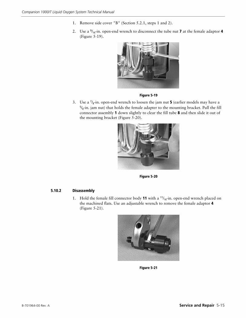
B-701964-00 Rev. A Service and Repair 5-15
Companion 1000/T Liquid Oxygen System Technical Manual
1. Remove side cover "B" (Section 5.2.1, steps 1 and 2).
2. Use a 9/16-in. open-end wrench to disconnect the tube nut 7 at the female adaptor 4 (Figure 5-19).
Figure 5-19
3. Use a 7/8-in. open-end wrench to loosen the jam nut 5 (earlier models may have a 5/8-in. jam nut) that holds the female adapter to the mounting bracket. Pull the fill connector assembly 1 down slightly to clear the fill tube 8 and then slide it out of the mounting bracket (Figure 5-20).
Figure 5-20
5.10.2 Disassembly
1. Hold the female fill connector body 11 with a 11/16-in. open-end wrench placed on the machined flats. Use an adjustable wrench to remove the female adaptor 4 (Figure 5-21).
Figure 5-21
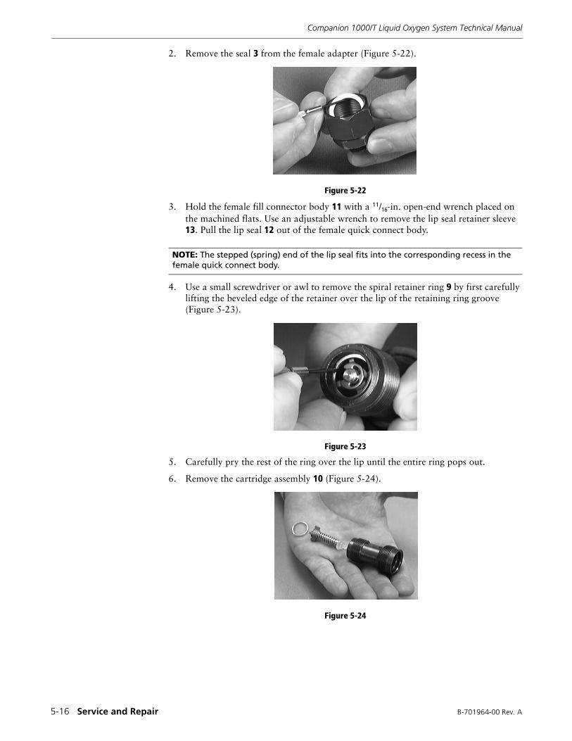
Companion 1000/T Liquid Oxygen System Technical Manual
5-16 Service and Repair B-701964-00 Rev. A
2. Remove the seal 3 from the female adapter (Figure 5-22).
Figure 5-22
3. Hold the female fill connector body 11 with a 11/16-in. open-end wrench placed on the machined flats. Use an adjustable wrench to remove the lip seal retainer sleeve 13. Pull the lip seal 12 out of the female quick connect body.
4. Use a small screwdriver or awl to remove the spiral retainer ring 9 by first carefully lifting the beveled edge of the retainer over the lip of the retaining ring groove (Figure 5-23).
Figure 5-23
5. Carefully pry the rest of the ring over the lip until the entire ring pops out.
6. Remove the cartridge assembly 10 (Figure 5-24).
Figure 5-24
NOTE: The stepped (spring) end of the lip seal fits into the corresponding recess in the female quick connect body.
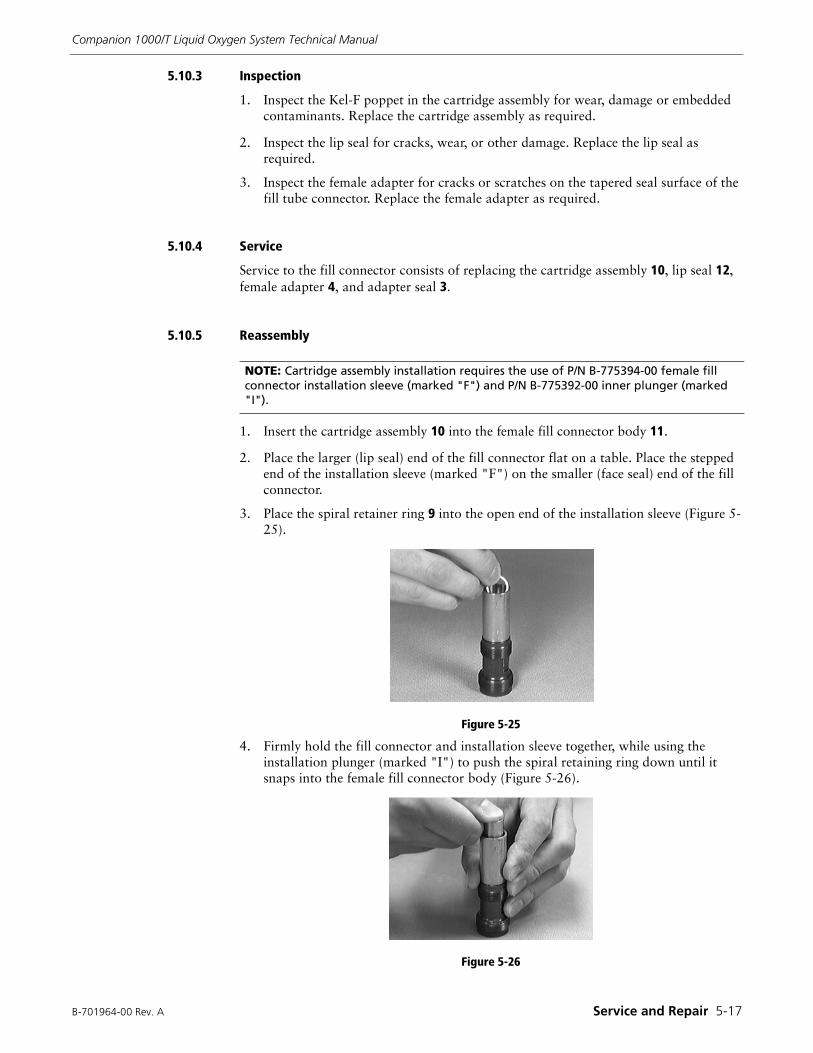
B-701964-00 Rev. A Service and Repair 5-17
Companion 1000/T Liquid Oxygen System Technical Manual
5.10.3 Inspection
1. Inspect the Kel-F poppet in the cartridge assembly for wear, damage or embedded contaminants. Replace the cartridge assembly as required.
2. Inspect the lip seal for cracks, wear, or other damage. Replace the lip seal as required.
3. Inspect the female adapter for cracks or scratches on the tapered seal surface of the fill tube connector. Replace the female adapter as required.
5.10.4 Service
Service to the fill connector consists of replacing the cartridge assembly 10, lip seal 12, female adapter 4, and adapter seal 3.
5.10.5 Reassembly
1. Insert the cartridge assembly 10 into the female fill connector body 11.
2. Place the larger (lip seal) end of the fill connector flat on a table. Place the stepped end of the installation sleeve (marked "F") on the smaller (face seal) end of the fill connector.
3. Place the spiral retainer ring 9 into the open end of the installation sleeve (Figure 5-25).
Figure 5-25
4. Firmly hold the fill connector and installation sleeve together, while using the installation plunger (marked "I") to push the spiral retaining ring down until it snaps into the female fill connector body (Figure 5-26).
Figure 5-26
NOTE: Cartridge assembly installation requires the use of P/N B-775394-00 female fill connector installation sleeve (marked "F") and P/N B-775392-00 inner plunger (marked "I").
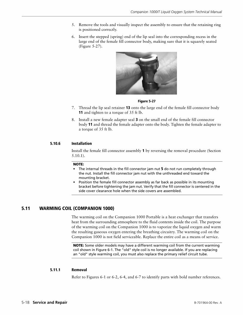
Companion 1000/T Liquid Oxygen System Technical Manual
5-18 Service and Repair B-701964-00 Rev. A
5. Remove the tools and visually inspect the assembly to ensure that the retaining ring is positioned correctly.
6. Insert the stepped (spring) end of the lip seal into the corresponding recess in the large end of the female fill connector body, making sure that it is squarely seated (Figure 5-27).
Figure 5-27
7. Thread the lip seal retainer 13 onto the large end of the female fill connector body 11 and tighten to a torque of 35 ft lb.
8. Install a new female adapter seal 3 on the small end of the female fill connector body 11 and thread the female adapter onto the body. Tighten the female adapter to a torque of 35 ft lb.
5.10.6 Installation
Install the female fill connector assembly 1 by reversing the removal procedure (Section 5.10.1).
5.11 WARMING COIL (COMPANION 1000)
The warming coil on the Companion 1000 Portable is a heat exchanger that transfers heat from the surrounding atmosphere to the fluid contents inside the coil. The purpose of the warming coil on the Companion 1000 is to vaporize the liquid oxygen and warm the resulting gaseous oxygen entering the breathing circuitry. The warming coil on the Companion 1000 is not field serviceable. Replace the entire coil as a means of service.
5.11.1 Removal
Refer to Figures 6-1 or 6-2, 6-4, and 6-7 to identify parts with bold number references.
NOTE: • The internal threads in the fill connector jam nut 5 do not run completely through
the nut. Install the fill connector jam nut with the unthreaded end toward the mounting bracket.
• Position the female fill connector assembly as far back as possible in its mounting bracket before tightening the jam nut. Verify that the fill connector is centered in the side cover clearance hole when the side covers are assembled.
NOTE: Some older models may have a different warming coil from the current warming coil shown in Figure 6-1. The "old" style coil is no longer available. If you are replacing an "old" style warming coil, you must also replace the primary relief circuit tube.
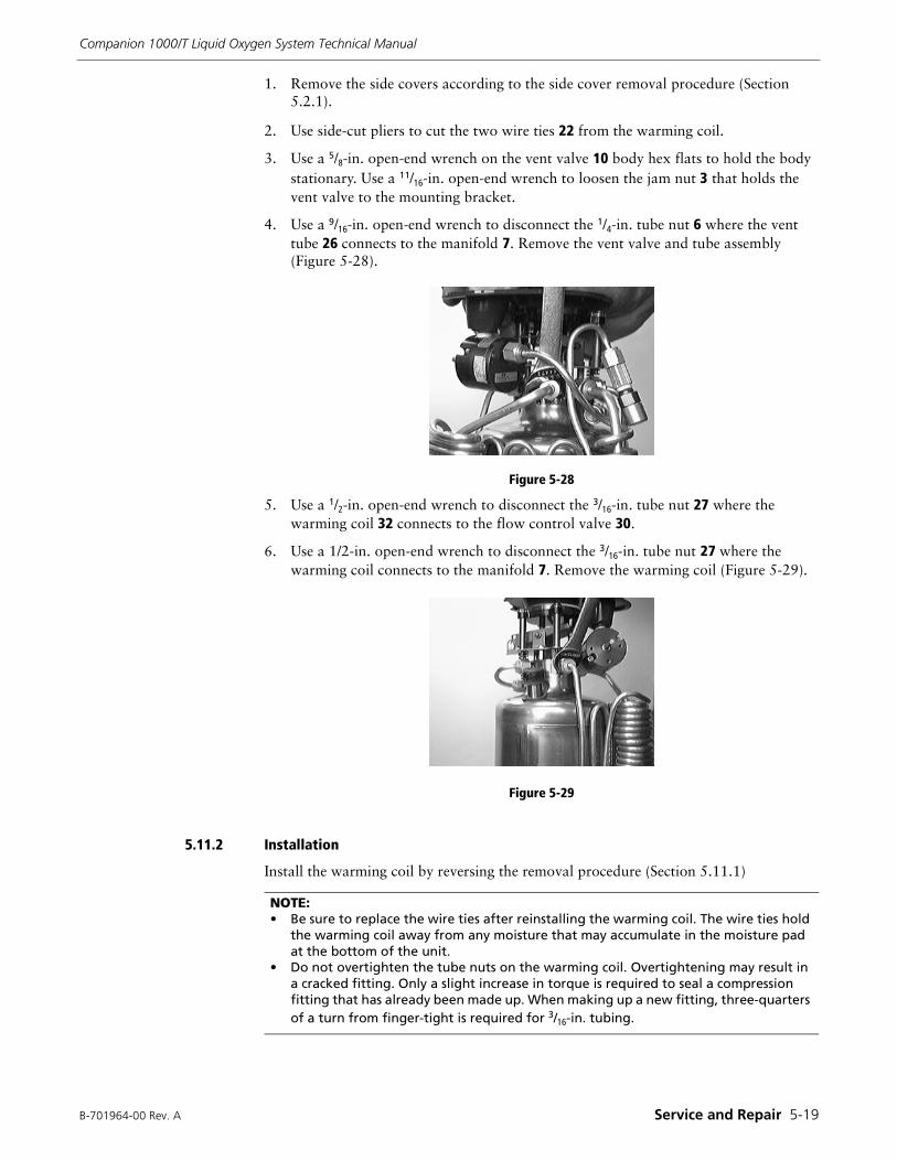
B-701964-00 Rev. A Service and Repair 5-19
Companion 1000/T Liquid Oxygen System Technical Manual
1. Remove the side covers according to the side cover removal procedure (Section 5.2.1).
2. Use side-cut pliers to cut the two wire ties 22 from the warming coil.
3. Use a 5/8-in. open-end wrench on the vent valve 10 body hex flats to hold the body stationary. Use a 11/16-in. open-end wrench to loosen the jam nut 3 that holds the vent valve to the mounting bracket.
4. Use a 9/16-in. open-end wrench to disconnect the 1/4-in. tube nut 6 where the vent tube 26 connects to the manifold 7. Remove the vent valve and tube assembly (Figure 5-28).
Figure 5-28
5. Use a 1/2-in. open-end wrench to disconnect the 3/16-in. tube nut 27 where the warming coil 32 connects to the flow control valve 30.
6. Use a 1/2-in. open-end wrench to disconnect the 3/16-in. tube nut 27 where the warming coil connects to the manifold 7. Remove the warming coil (Figure 5-29).
Figure 5-29
5.11.2 Installation
Install the warming coil by reversing the removal procedure (Section 5.11.1)
NOTE:• Be sure to replace the wire ties after reinstalling the warming coil. The wire ties hold
the warming coil away from any moisture that may accumulate in the moisture pad at the bottom of the unit.
• Do not overtighten the tube nuts on the warming coil. Overtightening may result in a cracked fitting. Only a slight increase in torque is required to seal a compression fitting that has already been made up. When making up a new fitting, three-quarters of a turn from finger-tight is required for 3/16-in. tubing.
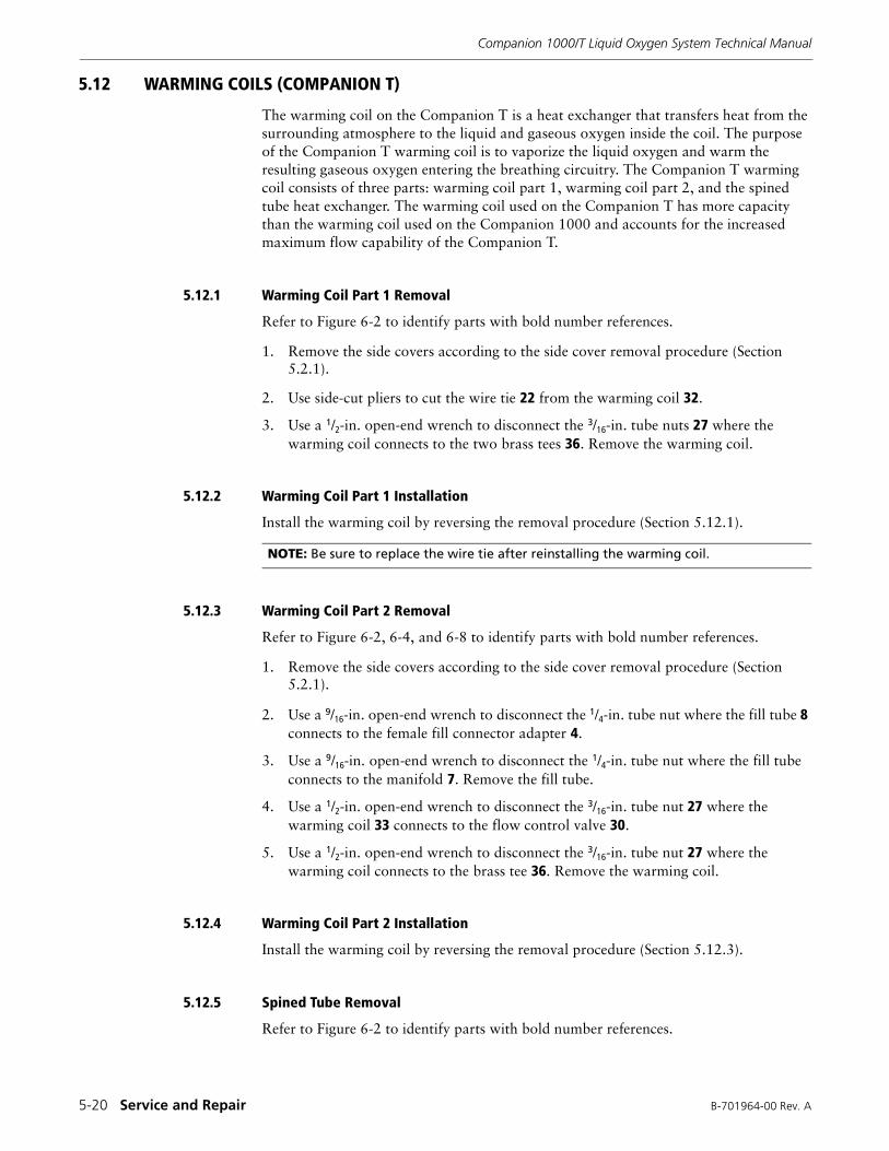
Companion 1000/T Liquid Oxygen System Technical Manual
5-20 Service and Repair B-701964-00 Rev. A
5.12 WARMING COILS (COMPANION T)
The warming coil on the Companion T is a heat exchanger that transfers heat from the surrounding atmosphere to the liquid and gaseous oxygen inside the coil. The purpose of the Companion T warming coil is to vaporize the liquid oxygen and warm the resulting gaseous oxygen entering the breathing circuitry. The Companion T warming coil consists of three parts: warming coil part 1, warming coil part 2, and the spined tube heat exchanger. The warming coil used on the Companion T has more capacity than the warming coil used on the Companion 1000 and accounts for the increased maximum flow capability of the Companion T.
5.12.1 Warming Coil Part 1 Removal
Refer to Figure 6-2 to identify parts with bold number references.
1. Remove the side covers according to the side cover removal procedure (Section 5.2.1).
2. Use side-cut pliers to cut the wire tie 22 from the warming coil 32.
3. Use a 1/2-in. open-end wrench to disconnect the 3/16-in. tube nuts 27 where the warming coil connects to the two brass tees 36. Remove the warming coil.
5.12.2 Warming Coil Part 1 Installation
Install the warming coil by reversing the removal procedure (Section 5.12.1).
5.12.3 Warming Coil Part 2 Removal
Refer to Figure 6-2, 6-4, and 6-8 to identify parts with bold number references.
1. Remove the side covers according to the side cover removal procedure (Section 5.2.1).
2. Use a 9/16-in. open-end wrench to disconnect the 1/4-in. tube nut where the fill tube 8 connects to the female fill connector adapter 4.
3. Use a 9/16-in. open-end wrench to disconnect the 1/4-in. tube nut where the fill tube connects to the manifold 7. Remove the fill tube.
4. Use a 1/2-in. open-end wrench to disconnect the 3/16-in. tube nut 27 where the warming coil 33 connects to the flow control valve 30.
5. Use a 1/2-in. open-end wrench to disconnect the 3/16-in. tube nut 27 where the warming coil connects to the brass tee 36. Remove the warming coil.
5.12.4 Warming Coil Part 2 Installation
Install the warming coil by reversing the removal procedure (Section 5.12.3).
5.12.5 Spined Tube Removal
Refer to Figure 6-2 to identify parts with bold number references.
NOTE: Be sure to replace the wire tie after reinstalling the warming coil.
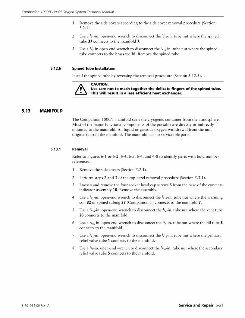
B-701964-00 Rev. A Service and Repair 5-21
Companion 1000/T Liquid Oxygen System Technical Manual
1. Remove the side covers according to the side cover removal procedure (Section 5.2.1).
2. Use a 1/2-in. open-end wrench to disconnect the 3/16-in. tube nut where the spined tube 37 connects to the manifold 7.
3. Use a 1/2-in open-end wrench to disconnect the 3/16-in. tube nut where the spined tube connects to the brass tee 36. Remove the spined tube.
5.12.6 Spined Tube Installation
Install the spined tube by reversing the removal procedure (Section 5.12.5).
5.13 MANIFOLD
The Companion 1000/T manifold seals the cryogenic container from the atmosphere. Most of the major functional components of the portable are directly or indirectly mounted to the manifold. All liquid or gaseous oxygen withdrawal from the unit originates from the manifold. The manifold has no serviceable parts.
5.13.1 Removal
Refer to Figures 6-1 or 6-2, 6-4, 6-5, 6-6, and 6-8 to identify parts with bold number references.
1. Remove the side covers (Section 5.2.1).
2. Perform steps 2 and 3 of the top bezel removal procedure (Section 5.3.1).
3. Loosen and remove the four socket head cap screws 6 from the base of the contents indicator assembly 16. Remove the assembly.
4. Use a 1/2-in. open-end wrench to disconnect the 3/16-in. tube nut where the warming coil 32 or spined tubing 37 (Companion T) connects to the manifold 7.
5. Use a 9/16-in. open-end wrench to disconnect the 1/4-in. tube nut where the vent tube 26 connects to the manifold.
6. Use a 9/16-in. open-end wrench to disconnect the 1/4-in. tube nut where the fill tube 8 connects to the manifold.
7. Use a 1/2-in. open-end wrench to disconnect the 3/16-in. tube nut where the primary relief valve tube 1 connects to the manifold.
8. Use a 1/2-in. open-end wrench to disconnect the 3/16-in. tube nut where the secondary relief valve tube 5 connects to the manifold.
CAUTION:Use care not to mash together the delicate fingers of the spined tube. This will result in a less efficient heat exchanger.
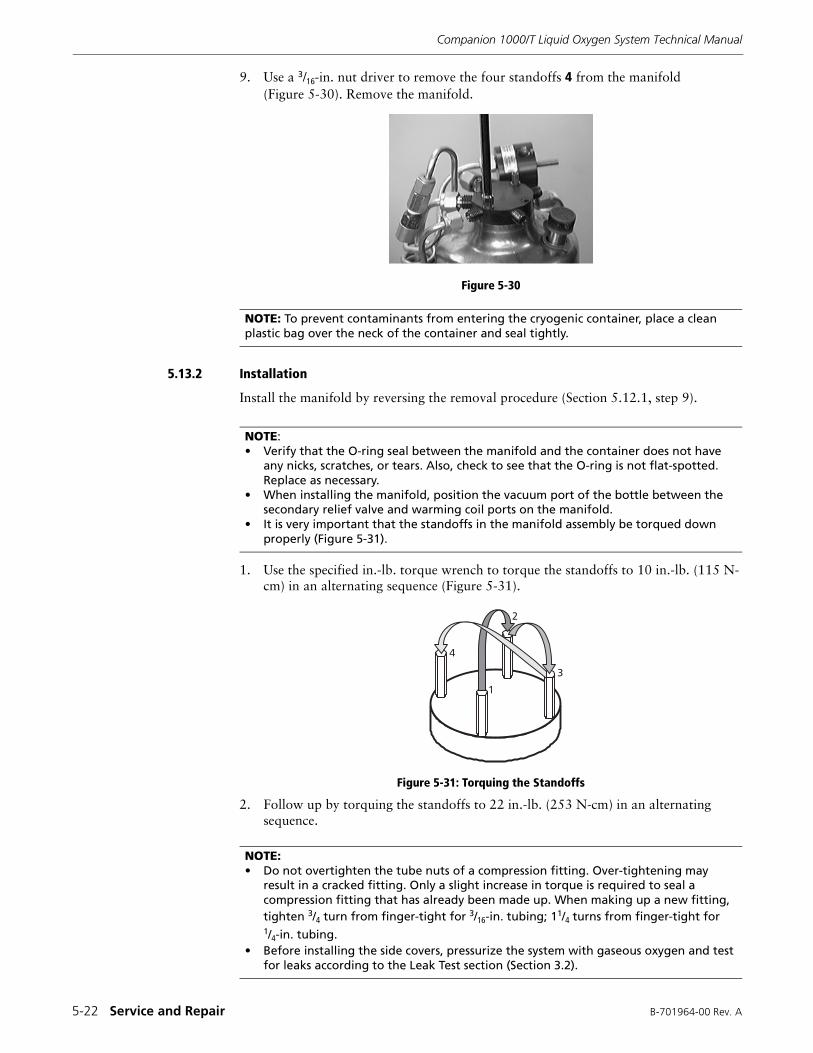
Companion 1000/T Liquid Oxygen System Technical Manual
5-22 Service and Repair B-701964-00 Rev. A
9. Use a 3/16-in. nut driver to remove the four standoffs 4 from the manifold (Figure 5-30). Remove the manifold.
Figure 5-30
5.13.2 Installation
Install the manifold by reversing the removal procedure (Section 5.12.1, step 9).
1. Use the specified in.-lb. torque wrench to torque the standoffs to 10 in.-lb. (115 N-cm) in an alternating sequence (Figure 5-31).
Figure 5-31: Torquing the Standoffs
2. Follow up by torquing the standoffs to 22 in.-lb. (253 N-cm) in an alternating sequence.
NOTE: To prevent contaminants from entering the cryogenic container, place a clean plastic bag over the neck of the container and seal tightly.
NOTE:• Verify that the O-ring seal between the manifold and the container does not have
any nicks, scratches, or tears. Also, check to see that the O-ring is not flat-spotted. Replace as necessary.
• When installing the manifold, position the vacuum port of the bottle between the secondary relief valve and warming coil ports on the manifold.
• It is very important that the standoffs in the manifold assembly be torqued down properly (Figure 5-31).
NOTE: • Do not overtighten the tube nuts of a compression fitting. Over-tightening may
result in a cracked fitting. Only a slight increase in torque is required to seal a compression fitting that has already been made up. When making up a new fitting, tighten 3/4 turn from finger-tight for 3/16-in. tubing; 11/4 turns from finger-tight for 1/4-in. tubing.
• Before installing the side covers, pressurize the system with gaseous oxygen and test for leaks according to the Leak Test section (Section 3.2).
1
2
3
4
B-701964-00 Rev. A Service and Repair 5-23
Companion 1000/T Liquid Oxygen System Technical Manual
5.14 CRYOGENIC CONTAINER
The Companion 1000/T Portable cryogenic container is a stainless steel, double-walled, vacuum-insulated container that holds liquid oxygen. The container’s main function is to limit the amount of heat that leaks into the container from the surrounding atmosphere. The container is not field serviceable.
5.14.1 Removal
Refer to Figures 6-1 or 6-2, 6-7, and 6-8 to identify parts with bold number references.
1. Remove the manifold 7 (Section 5.13.1).
2. Use a 5/8-in. open-end wrench on the vent valve body hex flats to hold the body stationary. Use a 11/16-in. open-end wrench to loosen the jam nut 3 that holds the vent valve to the mounting bracket. Remove the vent valve and tube assembly from the mounting bracket.
3. Use side-cut pliers to cut the wire tie 22 from the warming coil.
4. Use a 7/8-in. open-end wrench to loosen the jam nut 5 (some earlier models may have a 5/8-in. jam nut) that retains the female adapter to the mounting bracket. Remove the female fill connector and tube assembly from the mounting bracket.
5.14.2 Installation
Install the cryogenic container by reversing the removal procedure (Section 5.14.1).
5.15 RETURNING THE UNIT FOR SERVICE
To return a product, contact Puritan-Bennett at 1-800-255-6774 (press 2) and ask to speak with a Technical Support Representative. A Return Goods Authorization (RGA) number will be issued to track the product return. Please have available your account number, the model and serial number of the product, and the reason for returning the product when you call to request an RGA. Return the unit in its original carton, if possible. If the original carton is not available, you may purchase a new carton (Section 1.12, Accessories).
NOTE: To prevent contaminants from entering the cryogenic container, place the container in a clean plastic bag and seal tightly.
WARNING
Fire hazard and extreme cold hazard. Do not package or ship units that contain liquid or gaseous oxygen. Liquid oxygen spillage and high oxygen concentrations are possible. Empty oxygen contents completely before packaging or shipping units.

Companion 1000/T Liquid Oxygen System Technical Manual
5-24 Service and Repair B-701964-00 Rev. A
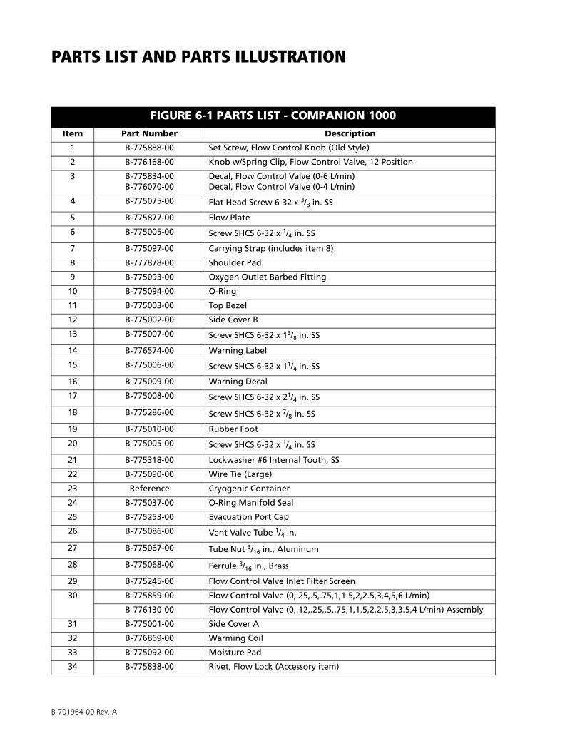
B-701964-00 Rev. A
PARTS LIST AND PARTS ILLUSTRATION
FIGURE 6-1 PARTS LIST - COMPANION 1000Item Part Number Description
1 B-775888-00 Set Screw, Flow Control Knob (Old Style)
2 B-776168-00 Knob w/Spring Clip, Flow Control Valve, 12 Position
3 B-775834-00B-776070-00
Decal, Flow Control Valve (0-6 L/min)Decal, Flow Control Valve (0-4 L/min)
4 B-775075-00 Flat Head Screw 6-32 x 3/8 in. SS
5 B-775877-00 Flow Plate
6 B-775005-00 Screw SHCS 6-32 x 1/4 in. SS
7 B-775097-00 Carrying Strap (includes item 8)
8 B-777878-00 Shoulder Pad
9 B-775093-00 Oxygen Outlet Barbed Fitting
10 B-775094-00 O-Ring
11 B-775003-00 Top Bezel
12 B-775002-00 Side Cover B
13 B-775007-00 Screw SHCS 6-32 x 13/8 in. SS
14 B-776574-00 Warning Label
15 B-775006-00 Screw SHCS 6-32 x 11/4 in. SS
16 B-775009-00 Warning Decal
17 B-775008-00 Screw SHCS 6-32 x 21/4 in. SS
18 B-775286-00 Screw SHCS 6-32 x 7/8 in. SS
19 B-775010-00 Rubber Foot
20 B-775005-00 Screw SHCS 6-32 x 1/4 in. SS
21 B-775318-00 Lockwasher #6 Internal Tooth, SS
22 B-775090-00 Wire Tie (Large)
23 Reference Cryogenic Container
24 B-775037-00 O-Ring Manifold Seal
25 B-775253-00 Evacuation Port Cap
26 B-775086-00 Vent Valve Tube 1/4 in.
27 B-775067-00 Tube Nut 3/16 in., Aluminum
28 B-775068-00 Ferrule 3/16 in., Brass
29 B-775245-00 Flow Control Valve Inlet Filter Screen
30 B-775859-00 Flow Control Valve (0,.25,.5,.75,1,1.5,2,2.5,3,4,5,6 L/min)
B-776130-00 Flow Control Valve (0,.12,.25,.5,.75,1,1.5,2,2.5,3,3.5,4 L/min) Assembly
31 B-775001-00 Side Cover A
32 B-776869-00 Warming Coil
33 B-775092-00 Moisture Pad
34 B-775838-00 Rivet, Flow Lock (Accessory item)
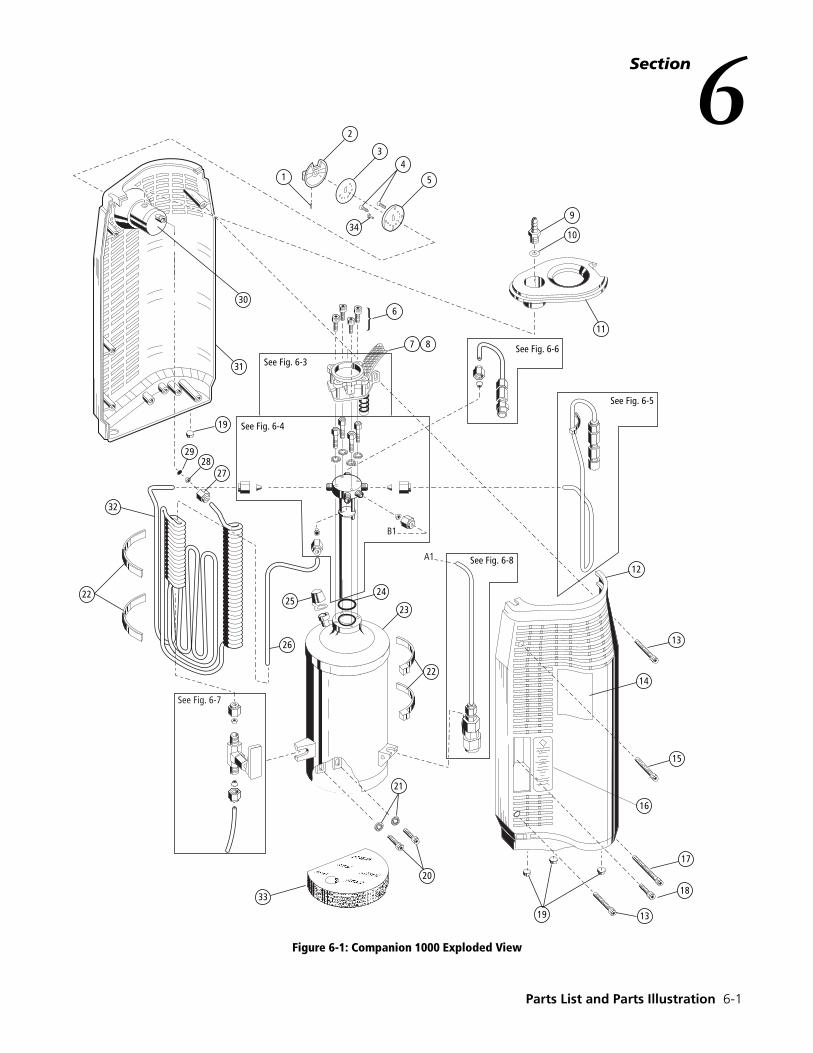
Parts List and Parts Illustration 6-1
Section6
Figure 6-1: Companion 1000 Exploded View
�
�
�
�
�
�
��
��
��� �� ���
��� �� ���
��� �� ���
��� �� ���
��� �� ���
��
��
��
��
��
��
��
����
��
��
��
��� �� ���
��
��
��
��
��
��
��
��
��
��
�
��
� �
��
��
��
��
��
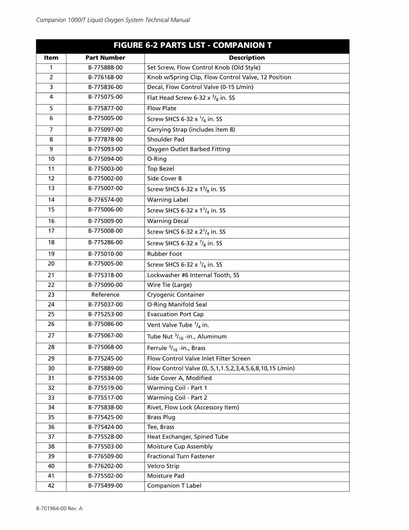
B-701964-00 Rev. A
Companion 1000/T Liquid Oxygen System Technical Manual
FIGURE 6-2 PARTS LIST - COMPANION TItem Part Number Description
1 B-775888-00 Set Screw, Flow Control Knob (Old Style)
2 B-776168-00 Knob w/Spring Clip, Flow Control Valve, 12 Position
3 B-775836-00 Decal, Flow Control Valve (0-15 L/min)
4 B-775075-00 Flat Head Screw 6-32 x 3/8 in. SS
5 B-775877-00 Flow Plate
6 B-775005-00 Screw SHCS 6-32 x 1/4 in. SS
7 B-775097-00 Carrying Strap (includes item 8)
8 B-777878-00 Shoulder Pad
9 B-775093-00 Oxygen Outlet Barbed Fitting
10 B-775094-00 O-Ring
11 B-775003-00 Top Bezel
12 B-775002-00 Side Cover B
13 B-775007-00 Screw SHCS 6-32 x 13/8 in. SS
14 B-776574-00 Warning Label
15 B-775006-00 Screw SHCS 6-32 x 11/4 in. SS
16 B-775009-00 Warning Decal
17 B-775008-00 Screw SHCS 6-32 x 21/4 in. SS
18 B-775286-00 Screw SHCS 6-32 x 7/8 in. SS
19 B-775010-00 Rubber Foot
20 B-775005-00 Screw SHCS 6-32 x 1/4 in. SS
21 B-775318-00 Lockwasher #6 Internal Tooth, SS
22 B-775090-00 Wire Tie (Large)
23 Reference Cryogenic Container
24 B-775037-00 O-Ring Manifold Seal
25 B-775253-00 Evacuation Port Cap
26 B-775086-00 Vent Valve Tube 1/4 in.
27 B-775067-00 Tube Nut 3/16 -in., Aluminum
28 B-775068-00 Ferrule 3/16 -in., Brass
29 B-775245-00 Flow Control Valve Inlet Filter Screen
30 B-775889-00 Flow Control Valve (0,.5,1,1.5,2,3,4,5,6,8,10,15 L/min)
31 B-775534-00 Side Cover A, Modified
32 B-775519-00 Warming Coil - Part 1
33 B-775517-00 Warming Coil - Part 2
34 B-775838-00 Rivet, Flow Lock (Accessory Item)
35 B-775425-00 Brass Plug
36 B-775424-00 Tee, Brass
37 B-775528-00 Heat Exchanger, Spined Tube
38 B-775503-00 Moisture Cup Assembly
39 B-776509-00 Fractional Turn Fastener
40 B-776202-00 Velcro Strip
41 B-775502-00 Moisture Pad
42 B-775499-00 Companion T Label
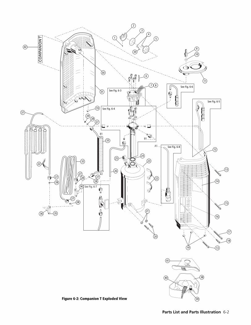
Parts List and Parts Illustration 6-2
CO
MPA
NIO
N T 1
2
34
5
9
10
11
See Fig. 6-5
See Fig. 6-6
See Fig. 6-8
See Fig. 6-4
See Fig. 6-3
12
13
14
15
16
17
18
38
39
1319
20
21
40
41
See Fig. 6-7
26
2727
27
28
2728
28
28
33
37
25
2728
19
31
30
42
6
29
7 8
24
23
22
B1
A1
22
36 35
32
34
36
A1
B1
Figure 6-2: Companion T Exploded View
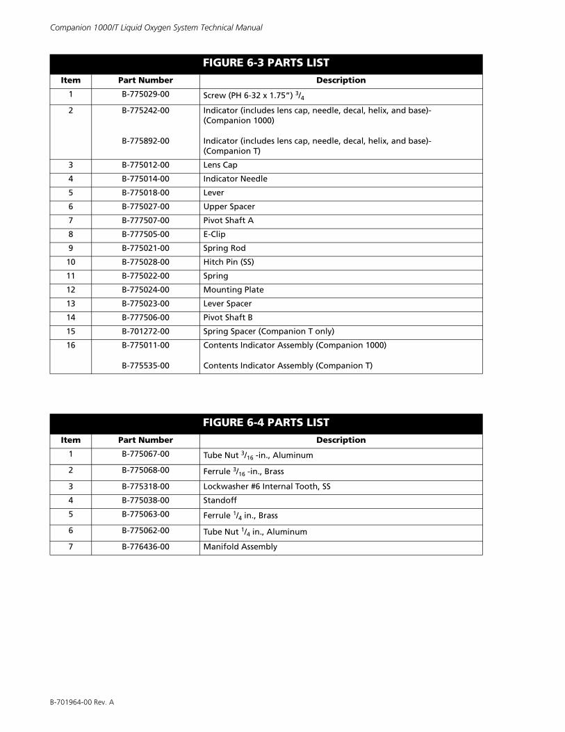
B-701964-00 Rev. A
Companion 1000/T Liquid Oxygen System Technical Manual
FIGURE 6-3 PARTS LISTItem Part Number Description
1 B-775029-00 Screw (PH 6-32 x 1.75”) 3/4
2 B-775242-00
B-775892-00
Indicator (includes lens cap, needle, decal, helix, and base)-(Companion 1000)
Indicator (includes lens cap, needle, decal, helix, and base)-(Companion T)
3 B-775012-00 Lens Cap
4 B-775014-00 Indicator Needle
5 B-775018-00 Lever
6 B-775027-00 Upper Spacer
7 B-777507-00 Pivot Shaft A
8 B-777505-00 E-Clip
9 B-775021-00 Spring Rod
10 B-775028-00 Hitch Pin (SS)
11 B-775022-00 Spring
12 B-775024-00 Mounting Plate
13 B-775023-00 Lever Spacer
14 B-777506-00 Pivot Shaft B
15 B-701272-00 Spring Spacer (Companion T only)
16 B-775011-00
B-775535-00
Contents Indicator Assembly (Companion 1000)
Contents Indicator Assembly (Companion T)
FIGURE 6-4 PARTS LISTItem Part Number Description
1 B-775067-00 Tube Nut 3/16 -in., Aluminum
2 B-775068-00 Ferrule 3/16 -in., Brass
3 B-775318-00 Lockwasher #6 Internal Tooth, SS
4 B-775038-00 Standoff
5 B-775063-00 Ferrule 1/4 in., Brass
6 B-775062-00 Tube Nut 1/4 in., Aluminum
7 B-776436-00 Manifold Assembly
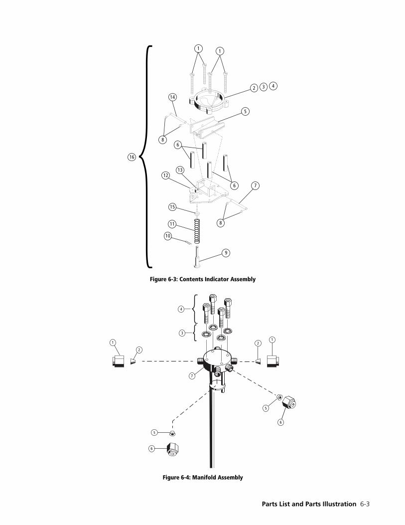
Parts List and Parts Illustration 6-3
Figure 6-3: Contents Indicator Assembly
Figure 6-4: Manifold Assembly
��
� � �
�
�
�
��
��
��
��
��
��
�
��
�
�
�
�
�
�
�
�
�
�
�
�
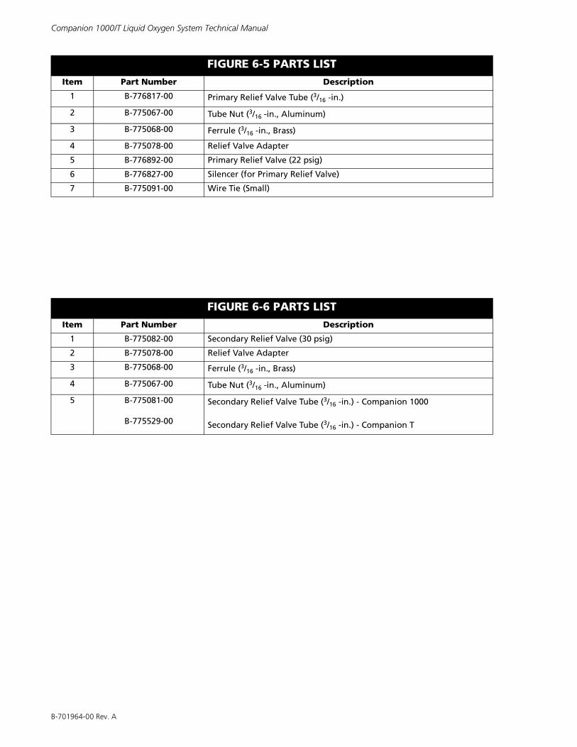
B-701964-00 Rev. A
Companion 1000/T Liquid Oxygen System Technical Manual
FIGURE 6-5 PARTS LISTItem Part Number Description
1 B-776817-00 Primary Relief Valve Tube (3/16 -in.)
2 B-775067-00 Tube Nut (3/16 -in., Aluminum)
3 B-775068-00 Ferrule (3/16 -in., Brass)
4 B-775078-00 Relief Valve Adapter
5 B-776892-00 Primary Relief Valve (22 psig)
6 B-776827-00 Silencer (for Primary Relief Valve)
7 B-775091-00 Wire Tie (Small)
FIGURE 6-6 PARTS LISTItem Part Number Description
1 B-775082-00 Secondary Relief Valve (30 psig)
2 B-775078-00 Relief Valve Adapter
3 B-775068-00 Ferrule (3/16 -in., Brass)
4 B-775067-00 Tube Nut (3/16 -in., Aluminum)
5 B-775081-00
B-775529-00
Secondary Relief Valve Tube (3/16 -in.) - Companion 1000
Secondary Relief Valve Tube (3/16 -in.) - Companion T
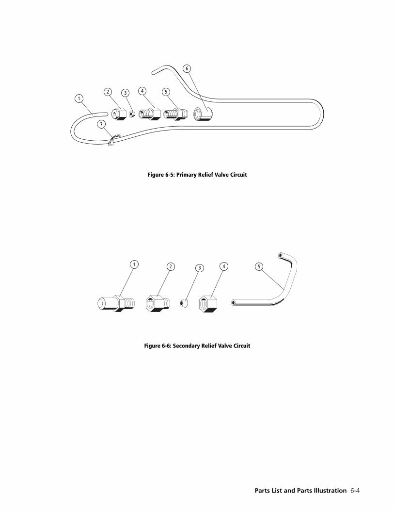
Parts List and Parts Illustration 6-4
Figure 6-5: Primary Relief Valve Circuit
Figure 6-6: Secondary Relief Valve Circuit
1
7
2 3 4 5
6
�� � � �
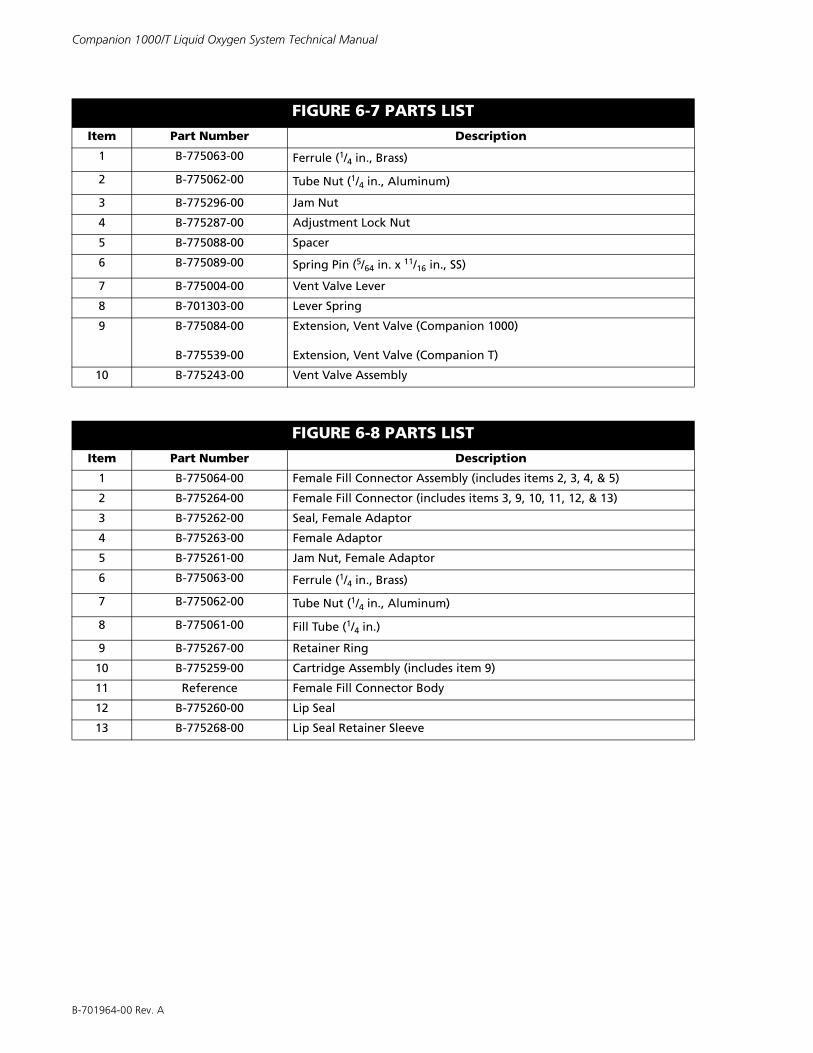
B-701964-00 Rev. A
Companion 1000/T Liquid Oxygen System Technical Manual
FIGURE 6-7 PARTS LISTItem Part Number Description
1 B-775063-00 Ferrule (1/4 in., Brass)
2 B-775062-00 Tube Nut (1/4 in., Aluminum)
3 B-775296-00 Jam Nut
4 B-775287-00 Adjustment Lock Nut
5 B-775088-00 Spacer
6 B-775089-00 Spring Pin (5/64 in. x 11/16 in., SS)
7 B-775004-00 Vent Valve Lever
8 B-701303-00 Lever Spring
9 B-775084-00
B-775539-00
Extension, Vent Valve (Companion 1000)
Extension, Vent Valve (Companion T)
10 B-775243-00 Vent Valve Assembly
FIGURE 6-8 PARTS LISTItem Part Number Description
1 B-775064-00 Female Fill Connector Assembly (includes items 2, 3, 4, & 5)
2 B-775264-00 Female Fill Connector (includes items 3, 9, 10, 11, 12, & 13)
3 B-775262-00 Seal, Female Adaptor
4 B-775263-00 Female Adaptor
5 B-775261-00 Jam Nut, Female Adaptor
6 B-775063-00 Ferrule (1/4 in., Brass)
7 B-775062-00 Tube Nut (1/4 in., Aluminum)
8 B-775061-00 Fill Tube (1/4 in.)
9 B-775267-00 Retainer Ring
10 B-775259-00 Cartridge Assembly (includes item 9)
11 Reference Female Fill Connector Body
12 B-775260-00 Lip Seal
13 B-775268-00 Lip Seal Retainer Sleeve
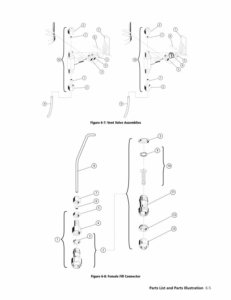
Parts List and Parts Illustration 6-5
Figure 6-7: Vent Valve Assemblies
Figure 6-8: Female Fill Connector
�
��
�
�
�
�
�
�
�
�
�
�
�
�
��
�
�� �
�
8
7
6
5
4
3
3
9
10
12
13
11
2
1