Embed Size (px)
Citation preview
Mitrović, D. M., et al.: Comparative Exergetic Performance Analysis for… THERMAL SCIENCE, Year 2016, Vol. 20, Suppl. 5, pp. S1259-S1269 S1259
COMPARATIVE EXERGETIC PERFORMANCE ANALYSIS FOR CERTAIN THERMAL POWER PLANTS IN SERBIA
by
Dejan M. MITROVI]*, Marko G. IGNJATOVI], Branislav V. STOJANOVI], Jelena N. JANEVSKI, and Mirko M. STOJILJKOVI]
Faculty of Mechanical Engineering, University of Nis, Nis, Serbia Original scientific paper
DOI: 10.2298/TSCI16S5259M
Traditional methods of analysis and calculation of complex thermal systems are based on the first law of thermodynamics. These methods use energy balance for a system. In general, energy balances do not provide any information about in-ternal losses. In contrast, the second law of thermodynamics introduces the con-cept of exergy, which is useful in the analysis of thermal systems. Exergy is a measure for assessing the quality of energy, and allows one to determine the lo-cation, cause, and real size of losses incurred as well as residues in a thermal process. The purpose of this study is to comparatively analyze the performance of four thermal power plants from the energetic and exergetic viewpoint. Thermo-dynamic models of the plants are developed based on the first and second law of thermodynamics. The primary objectives of this paper are to analyze the system components separately and to identify and quantify the sites having largest ener-gy and exergy losses. Finally, by means of these analyses, the main sources of thermodynamic inefficiencies as well as a reasonable comparison of each plant to others are identified and discussed. As a result, the outcomes of this study can provide a basis for the improvement of plant performance for the considered thermal power plants. Key words: power plant, efficiency, exergy, losses, destruction
Introduction
When two systems with different conditions interact, there is a tendency to create a state of equilibrium and there is a possibility to perform work. If one of the systems is as-sumed to be surroundings and the other the system being studied, exergy can be defined as the maximum possible work to be obtained when the two systems reach equilibrium, assuming that heat is exchanged only with the surroundings. Every system not in equilibrium with its surroundings can perform work, and a system in the equilibrium state with its surroundings, by definition, can not. Exergy can be treated as the measure or distance between the state of the system and the state of the surroundings. It becomes the attribute for both composition of the system and the surroundings. Exergy can be destroyed but it can not be conserved. In boundary cases, exergy is being completely destroyed, and this occurs when a system sponta-neously comes in equilibrium with its surroundings without performing work, i. e. the initial ability of the system to perform work gets consumed by the spontaneous process. Since no work is needed for spontaneous equilibrium, it can be concluded that exergy can have a min-
–––––––––––––– * Corresponding author; e-mail: [email protected]
Mitrović, D. M., et al.: Comparative Exergetic Performance Analysis for … S1260 THERMAL SCIENCE, Year 2016, Vol. 20, Suppl. 5, pp. S1259-S1269
imum value of zero, and it cannot be negative. One of the main characteristics of exergy is that it can be transferred between the systems.
Exergy analysis is a method that combines energy and mass conservation with the second law of thermodynamics. The exergy analysis method enables the determination of the location, cause and source of losses. This information can be useful in designing a new energy efficient system but also for improving the performance of existing systems. Exergy analysis provides an insight into and a possibility to find causes for thermodynamic inefficiency of the system.
The exergy analysis method has been applied to thermal plants by numerous re-searchers in order to obtain efficiency, and optimize and improve the operation of such plants. Results show that most of exergy destruction occurs during fuel combustion, more than 80% [1, 2]. Cihan et al. [3] and Ameri et al. [4] performed the exergy analysis for thermal power plants and showed that it can pinpoint components with high inefficiency. Kanoglu et al. [5] stressed out the importance of understanding energy and exergy efficiency in order to improve the operation of power plants. The exergy concept plays an important role in developing ener-gy policy by implementing the analysis for energy conversion or the impact of energy systems on the environment [6, 7].
Description of the system This paper analyzes two electricity production plants and one cogeneration plant.
The plants are the property of the Republic of Serbia, and their lifespan is more than 20 years. The classical thermal power plants use coal as primary fuel, while the combined power plant uses natural gas. In all three cases heating of the main condensate is done in low pressure heaters (LPH). Steam degasation is done in a deaerator (DA3), after which the supply water is heated in high-pressure heaters (HPH). The number of low and high pressure heaters varies from case to case and is given in tab. 1. The cogeneration plant has two additional heaters for the district heating system, which are bypassed when the plant is in the condensing operation mode. A steam boiler (SB) generates superheated steam with defined parameters. Steam from a turbine is used for heating the main condensate and supply water, for district heating and deaerator operation (Ep1, Ep2,...). After the expansion in the turbine, steam is completely condensed in a condenser (CN). The turbine set comprises a high pressure turbine (HTP), a medium pressure turbine (MTP), and a low pressure turbine (LTP). After the expansion in the high pressure turbine, reheating occurs, followed by the expansion in the medium and low pressure turbines. Technical details of the plants are given in tab. 1.
Numerical simulation of operation For simulation purposes, the software was developed, which uses Microsoft Excel as
the platform with built in Visual Basic for Applications, so the macros were written in the VBA editor. Thermodynamic properties were calculated by IAPWS-IF97 (water steam pro) method with VBA.
During simulation, the dependence of turbine efficiency on the design and construc-tive characteristics was taken into account. At the same time, turbine efficiency varied with operation and was a function of mass flow rates (loads) and other relevant parameters. Char-acteristics were obtained from measurements or directly from the component manufacturer.
There are methods in literature for calculating turbine internal efficiency for differ-ent operating regimes as functions of various parameters in graphic or analytical form. The most complete one is given in the paper by Spencer et al. [8]. This paper provides the method
Mitrović, D. M., et al.: Comparative Exergetic Performance Analysis for… THERMAL SCIENCE, Year 2016, Vol. 20, Suppl. 5, pp. S1259-S1269 S1261
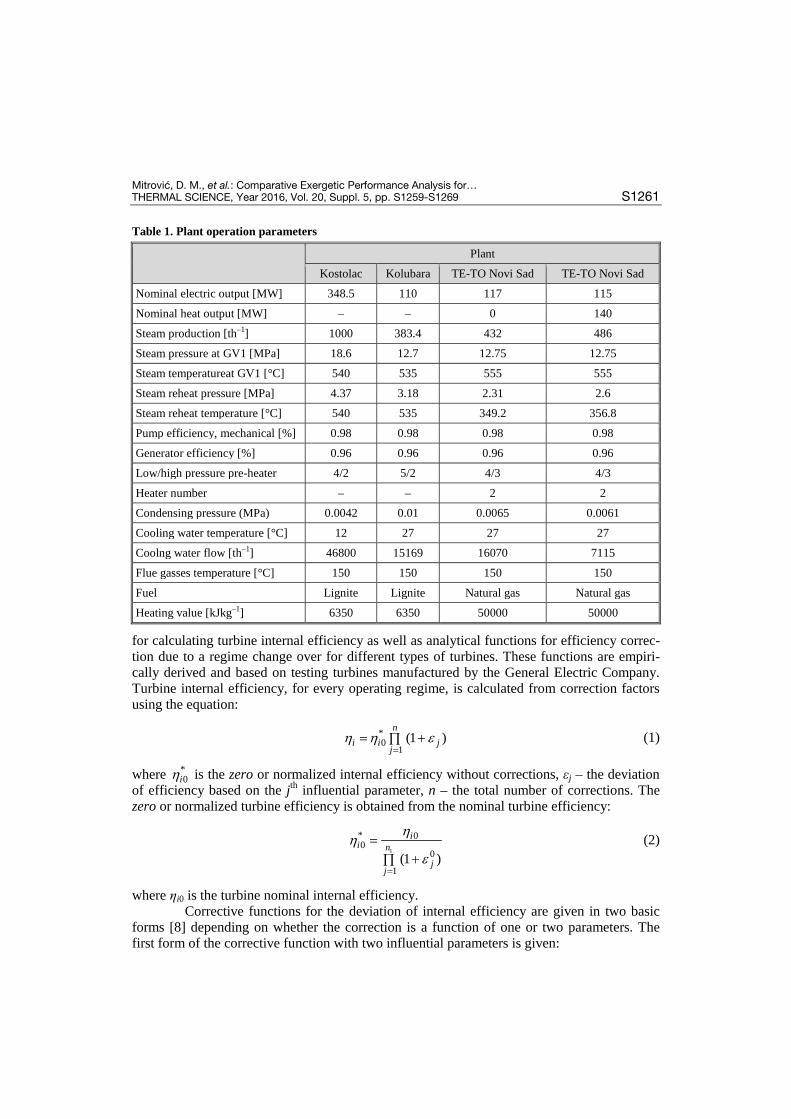
Table 1. Plant operation parameters
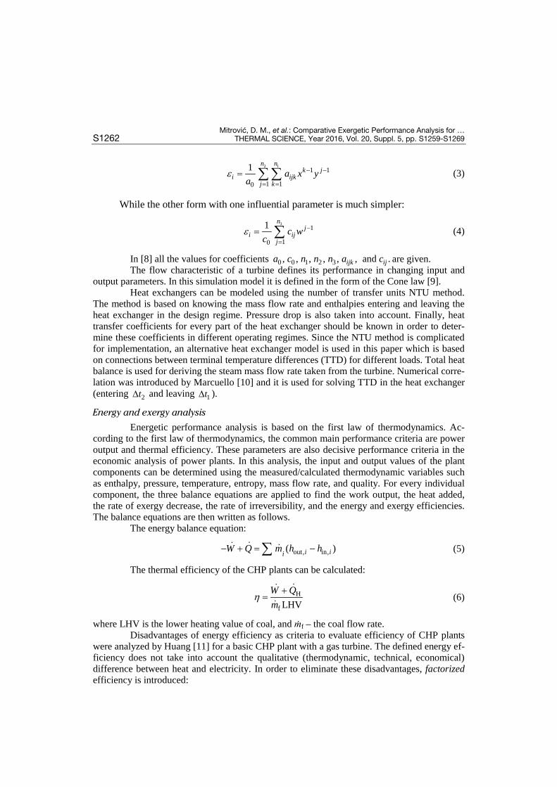
for calculating turbine internal efficiency as well as analytical functions for efficiency correc-tion due to a regime change over for different types of turbines. These functions are empiri-cally derived and based on testing turbines manufactured by the General Electric Company. Turbine internal efficiency, for every operating regime, is calculated from correction factors using the equation:
*0
1(1 )η η ε
== +∏
ni i j
j (1)
where *0iη is the zero or normalized internal efficiency without corrections, εj – the deviation
of efficiency based on the jth influential parameter, n – the total number of corrections. The zero or normalized turbine efficiency is obtained from the nominal turbine efficiency:
1
* 00
0
1(1 )
ηη
ε=
=+∏
ii n
jj
(2)
where ηi0 is the turbine nominal internal efficiency. Corrective functions for the deviation of internal efficiency are given in two basic
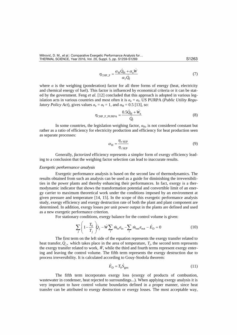
forms [8] depending on whether the correction is a function of one or two parameters. The first form of the corrective function with two influential parameters is given:
Plant
Kostolac Kolubara TE-TO Novi Sad TE-TO Novi Sad
Nominal electric output [MW] 348.5 110 117 115
Nominal heat output [MW] – – 0 140
Steam production [th–1] 1000 383.4 432 486
Steam pressure at GV1 [MPa] 18.6 12.7 12.75 12.75
Steam temperatureat GV1 [°C] 540 535 555 555
Steam reheat pressure [MPa] 4.37 3.18 2.31 2.6
Steam reheat temperature [°C] 540 535 349.2 356.8
Pump efficiency, mechanical [%] 0.98 0.98 0.98 0.98
Generator efficiency [%] 0.96 0.96 0.96 0.96
Low/high pressure pre-heater 4/2 5/2 4/3 4/3
Heater number – – 2 2
Condensing pressure (MPa) 0.0042 0.01 0.0065 0.0061
Cooling water temperature [°C] 12 27 27 27
Coolng water flow [th–1] 46800 15169 16070 7115
Flue gasses temperature [°C] 150 150 150 150
Fuel Lignite Lignite Natural gas Natural gas
Heating value [kJkg–1] 6350 6350 50000 50000
Mitrović, D. M., et al.: Comparative Exergetic Performance Analysis for … S1262 THERMAL SCIENCE, Year 2016, Vol. 20, Suppl. 5, pp. S1259-S1269
2 1
1 1
1 10
1 n nk j
i ijkj k
a x ya
ε − −
= == ∑∑ (3)
While the other form with one influential parameter is much simpler:
3
1
10
1 nj
i ijj
c wc
ε −
== ∑ (4)
In [8] all the values for coefficients 0 0 1 2 3, , , , , , and .ijk ija c n n n a c are given. The flow characteristic of a turbine defines its performance in changing input and
output parameters. In this simulation model it is defined in the form of the Cone law [9]. Heat exchangers can be modeled using the number of transfer units NTU method.
The method is based on knowing the mass flow rate and enthalpies entering and leaving the heat exchanger in the design regime. Pressure drop is also taken into account. Finally, heat transfer coefficients for every part of the heat exchanger should be known in order to deter-mine these coefficients in different operating regimes. Since the NTU method is complicated for implementation, an alternative heat exchanger model is used in this paper which is based on connections between terminal temperature differences (TTD) for different loads. Total heat balance is used for deriving the steam mass flow rate taken from the turbine. Numerical corre-lation was introduced by Marcuello [10] and it is used for solving TTD in the heat exchanger (entering 2t∆ and leaving 1t∆ ).
Energy and exergy analysis
Energetic performance analysis is based on the first law of thermodynamics. Ac-cording to the first law of thermodynamics, the common main performance criteria are power output and thermal efficiency. These parameters are also decisive performance criteria in the economic analysis of power plants. In this analysis, the input and output values of the plant components can be determined using the measured/calculated thermodynamic variables such as enthalpy, pressure, temperature, entropy, mass flow rate, and quality. For every individual component, the three balance equations are applied to find the work output, the heat added, the rate of exergy decrease, the rate of irreversibility, and the energy and exergy efficiencies. The balance equations are then written as follows.
The energy balance equation:
out, in,( )i iiW Q m h h− + = −∑
(5)
The thermal efficiency of the CHP plants can be calculated:
H
f LHVW Qm
η+
=
(6)
where LHV is the lower heating value of coal, and ṁf – the coal flow rate. Disadvantages of energy efficiency as criteria to evaluate efficiency of CHP plants
were analyzed by Huang [11] for a basic CHP plant with a gas turbine. The defined energy ef-ficiency does not take into account the qualitative (thermodynamic, technical, economical) difference between heat and electricity. In order to eliminate these disadvantages, factorized efficiency is introduced:
Mitrović, D. M., et al.: Comparative Exergetic Performance Analysis for… THERMAL SCIENCE, Year 2016, Vol. 20, Suppl. 5, pp. S1259-S1269 S1263
H H eCHP_F
f f
Q WQ
α αη
α+
=
(7)
where α is the weighing (ponderation) factor for all three forms of energy (heat, electricity and chemical energy of fuel). This factor is influenced by economical criteria or it can be stat-ed by the government. Feng et al. [12] concluded that this approach is adopted in various leg-islation acts in various countries and most often it is αe = αf. US PURPA (Public Utility Regu-latory Policy Act), gives values αe = αf = 1, and αH = 0.5 [13], so:
H eCHP_F_PURPA
f
0.5Q WQ
η+
=
(8)
In some countries, the legislation weighing factor, αH, is not considered constant but rather as a ratio of efficiency for electricity production and efficiency for heat production seen as separate processes:
e SEPH
t SEP
ηα
η= (9)
Generally, factorized efficiency represents a simpler form of exergy efficiency lead-ing to a conclusion that the weighing factor selection can lead to inaccurate results.
Exergetic performance analysis
Exergetic performance analysis is based on the second law of thermodynamics. The results obtained from such an analysis can be used as a guide for diminishing the irreversibili-ties in the power plants and thereby enhancing their performances. In fact, exergy is a ther-modynamic indicator that shows the transformation potential and convertible limit of an ener-gy carrier to maximum theoretical work under the conditions imposed by an environment at given pressure and temperature [14, 15]. In the scope of this exergetic performance analysis study, exergy efficiency and exergy destruction rate of both the plant and plant component are determined. In addition, exergy losses per unit power output in the plants are defined and used as a new exergetic performance criterion.
For stationary conditions, exergy balance for the control volume is given:
0in in out out D1 0j
j i ij
T Q W m e m e ET
− − − − =
∑ ∑ ∑
(10)
The first term on the left side of the equation represents the exergy transfer related to heat transfer, , jQ which takes place in the area of temperature, Tj, the second term represents the exergy transfer related to work, Ẇ, while the third and fourth terms represent exergy enter-ing and leaving the control volume. The fifth term represents the exergy destruction due to process irreversibility. It is calculated according to Gouy-Stodola theorem:
D 0 genE T S= (11)
The fifth term incorporates exergy loss (exergy of products of combustion, wastewater in condenser, heat rejected to surroundings...). When applying exergy analysis it is very important to have control volume boundaries defined in a proper manner, since heat transfer can be attributed to exergy destruction or exergy losses. The most acceptable way,
Mitrović, D. M., et al.: Comparative Exergetic Performance Analysis for … S1264 THERMAL SCIENCE, Year 2016, Vol. 20, Suppl. 5, pp. S1259-S1269
and the one which enables partial analysis, is to treat every component of the system as a sep-arate control volume.
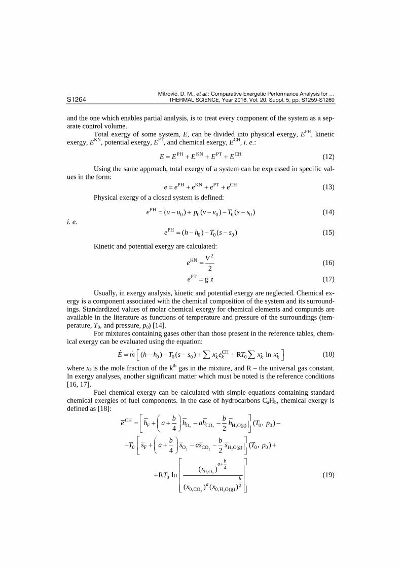
Total exergy of some system, E, can be divided into physical exergy, EPH, kinetic exergy, EKN, potential exergy, EPT, and chemical exergy, ECH, i. e.:
PH KN PT CHE E E E E= + + + (12)
Using the same approach, total exergy of a system can be expressed in specific val-ues in the form: PH KN PT CHe e e e e= + + + (13)
Physical exergy of a closed system is defined:
PH0 0 0 0 0( ) ( ) ( )e u u p v v T s s= − + − − − (14)
i. e. PH
0 0 0( ) ( )e h h T s s= − − − (15)
Kinetic and potential exergy are calculated:
2
KN
2Ve = (16)
PT ge z= (17)
Usually, in exergy analysis, kinetic and potential exergy are neglected. Chemical ex-ergy is a component associated with the chemical composition of the system and its surround-ings. Standardized values of molar chemical exergy for chemical elements and compunds are available in the literature as functions of temperature and pressure of the surroundings (tem-perature, T0, and pressure, p0) [14].
For mixtures containing gases other than those present in the reference tables, chem-ical exergy can be evaluated using the equation:
, CH , ,0 0 0 0( ) ( ) R ln = − − − + + ∑ ∑
kk k kE m h h T s s x e T x x (18)
where xk is the mole fraction of the kth gas in the mixture, and R – the universal gas constant. In exergy analyses, another significant matter which must be noted is the reference conditions [16, 17].
Fuel chemical exergy can be calculated with simple equations containing standard chemical exergies of fuel components. In the case of hydrocarbons CaHb, chemical exergy is defined as [18]:
2 2 2
2 2 2
CHF O CO H O(g) 0 0
0 F O CO H O(g) 0 0
( , )4 2
( , )4 2
b be h a h ah h T p
b bT s a s as s T p
= + + − − − − + + − − +
2
2 2
40,O
02
0,CO 0,H O(g)
( )R ln
( ) ( )
+
+
ba
ba
xT
x x
(19)
Mitrović, D. M., et al.: Comparative Exergetic Performance Analysis for… THERMAL SCIENCE, Year 2016, Vol. 20, Suppl. 5, pp. S1259-S1269 S1265
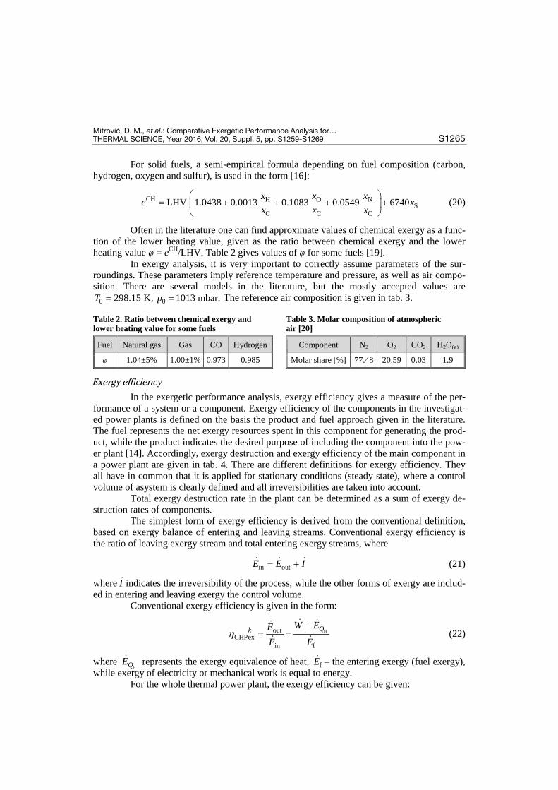
For solid fuels, a semi-empirical formula depending on fuel composition (carbon, hydrogen, oxygen and sulfur), is used in the form [16]:
CH O NHS
C C CLHV 1.0438 0.0013 0.1083 0.0549 6740x xxe x
x x x
= + + + +
(20)
Often in the literature one can find approximate values of chemical exergy as a func-tion of the lower heating value, given as the ratio between chemical exergy and the lower heating value φ = eCH/LHV. Table 2 gives values of φ for some fuels [19].
In exergy analysis, it is very important to correctly assume parameters of the sur-roundings. These parameters imply reference temperature and pressure, as well as air compo-sition. There are several models in the literature, but the mostly accepted values are
0 0298.15 K, 1013 mbar.T p= = The reference air composition is given in tab. 3.
Table 2. Ratio between chemical exergy and lower heating value for some fuels
Fuel Natural gas Gas CO Hydrogen
φ 1.04±5% 1.00±1% 0.973 0.985
Table 3. Molar composition of atmospheric air [20]
Component N2 O2 CO2 H2O(g)
Molar share [%] 77.48 20.59 0.03 1.9
Exergy efficiency
In the exergetic performance analysis, exergy efficiency gives a measure of the per-formance of a system or a component. Exergy efficiency of the components in the investigat-ed power plants is defined on the basis the product and fuel approach given in the literature. The fuel represents the net exergy resources spent in this component for generating the prod-uct, while the product indicates the desired purpose of including the component into the pow-er plant [14]. Accordingly, exergy destruction and exergy efficiency of the main component in a power plant are given in tab. 4. There are different definitions for exergy efficiency. They all have in common that it is applied for stationary conditions (steady state), where a control volume of asystem is clearly defined and all irreversibilities are taken into account.
Total exergy destruction rate in the plant can be determined as a sum of exergy de-struction rates of components.
The simplest form of exergy efficiency is derived from the conventional definition, based on exergy balance of entering and leaving streams. Conventional exergy efficiency is the ratio of leaving exergy stream and total entering exergy streams, where
in outE E I= + (21)
where I indicates the irreversibility of the process, while the other forms of exergy are includ-ed in entering and leaving exergy the control volume.
Conventional exergy efficiency is given in the form:
HoutCHPex
in f
Qk W EEE E
η+
= =
(22)
where HQE represents the exergy equivalence of heat, fE – the entering exergy (fuel exergy),
while exergy of electricity or mechanical work is equal to energy. For the whole thermal power plant, the exergy efficiency can be given:
Mitrović, D. M., et al.: Comparative Exergetic Performance Analysis for … S1266 THERMAL SCIENCE, Year 2016, Vol. 20, Suppl. 5, pp. S1259-S1269
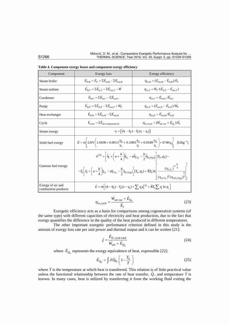
Table 4. Component exergy losses and component exergy efficiency
Hnet outex,cycle
f
QW E
Eη
+=
(23)
Exergetic efficiency acts as a basis for comparisons among cogeneration systems (of the same type) with different capacities of electricity and heat production, due to the fact that exergy quantifies the difference in the quality of the heat produced in different temperatures.
The other important exergetic performance criterion defined in this study is the amount of exergy loss rate per unit power and thermal output and it can be written [21]:
H
D, cycle total
net Q
E
W Eξ =
+
(24)
where HQE represents the exergy equivalence of heat, expressible [22]:
H
0H 1Q
TE QT
δ = − ∫ (25)
where T is the temperature at which heat is transferred. This relation is of little practical value unless the functional relationship between the rate of heat transfer, Q , and temperature T is known. In many cases, heat is utilized by transferring it from the working fluid exiting the
Component Exergy loss Exergy efficiency
Steam boiler D,B in,B out,BFE E E E= + Σ − Σ ex,B out,B in,B F( )/E E Eη = −
Steam turbine D,T in,T out,TE E E W= Σ − Σ − ex,T T in,T out,T/( )W E Eη = −
Condenser D,C in,C out,CE E E= Σ − Σ ex,C out,C in,C/E Eη =
Pump D,P in,P out,P PE E E W= Σ − Σ + ex,P out,P in,P P( )/E E Wη = −
Heat exchanger D,H in,H out,HE E E= Σ − Σ ex,H out,H in,H/E Eη =
Cycle cycle all components,DE E= Σ Hex,cycle net out f( )/QW E Eη = +
Steam exergy [ ]0 0 0( ) ( )i i ie h h T s s= − − −
Solid fuel exergy 1O NHS
C C CLHV 1.0438 0.0013 0.1083 0.0549 6740 [kJkg ]x xxE m x
x x x−
= + + + +
Gaseous fuel exergy
2 2 2
2
2 2 2
2 2
CHF O CO H O(g) 0 0
40,O
0 F O CO H O(g) 0 0 02
0,CO 0,H O(g)
( , )4 2
( )( , ) ln
4 2( ) ( )
ba
ba
b be h a h ah h T p
xb bT s a s as s T p RT
x x
+
= + + − − − − + + − − +
Exergy of air and combustion products
, CH , ,0 0 0 0( ) ( ) lnk k k kE m h h T s s x e RT x x = − − − + + ∑ ∑
Mitrović, D. M., et al.: Comparative Exergetic Performance Analysis for… THERMAL SCIENCE, Year 2016, Vol. 20, Suppl. 5, pp. S1259-S1269 S1267
heat producing device (e. g., turbine, internal combustion engine) to a secondary fluid, in a heat exchanger. One can express the exergy rate of heating as the exergy increase in the cold fluid in the heater [22]: cold cold 0 cold( )Q xE E m h T s= ∆ = ∆ − ∆
(26)
where Δh and Δs are the enthalpy and entropy changes of the cold fluid, respectively.
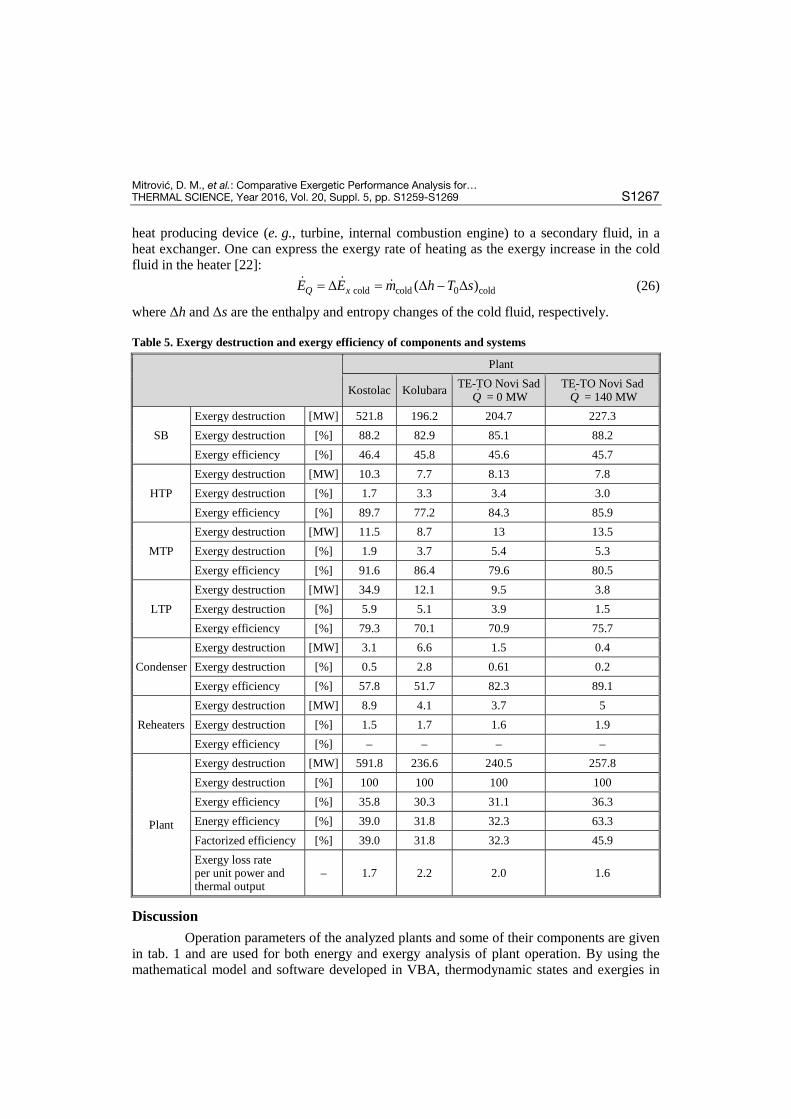
Table 5. Exergy destruction and exergy efficiency of components and systems
Discussion Operation parameters of the analyzed plants and some of their components are given
in tab. 1 and are used for both energy and exergy analysis of plant operation. By using the mathematical model and software developed in VBA, thermodynamic states and exergies in
Plant
Kostolac Kolubara TE-TO Novi Sad Q = 0 MW
TE-TO Novi Sad Q = 140 MW
SB Exergy destruction [MW] 521.8 196.2 204.7 227.3 Exergy destruction [%] 88.2 82.9 85.1 88.2 Exergy efficiency [%] 46.4 45.8 45.6 45.7
HTP Exergy destruction [MW] 10.3 7.7 8.13 7.8 Exergy destruction [%] 1.7 3.3 3.4 3.0 Exergy efficiency [%] 89.7 77.2 84.3 85.9
MTP Exergy destruction [MW] 11.5 8.7 13 13.5 Exergy destruction [%] 1.9 3.7 5.4 5.3 Exergy efficiency [%] 91.6 86.4 79.6 80.5
LTP Exergy destruction [MW] 34.9 12.1 9.5 3.8 Exergy destruction [%] 5.9 5.1 3.9 1.5 Exergy efficiency [%] 79.3 70.1 70.9 75.7
Condenser Exergy destruction [MW] 3.1 6.6 1.5 0.4 Exergy destruction [%] 0.5 2.8 0.61 0.2 Exergy efficiency [%] 57.8 51.7 82.3 89.1
Reheaters Exergy destruction [MW] 8.9 4.1 3.7 5 Exergy destruction [%] 1.5 1.7 1.6 1.9 Exergy efficiency [%] – – – –
Plant
Exergy destruction [MW] 591.8 236.6 240.5 257.8 Exergy destruction [%] 100 100 100 100 Exergy efficiency [%] 35.8 30.3 31.1 36.3 Energy efficiency [%] 39.0 31.8 32.3 63.3 Factorized efficiency [%] 39.0 31.8 32.3 45.9 Exergy loss rate per unit power and thermal output
– 1.7 2.2 2.0 1.6
Mitrović, D. M., et al.: Comparative Exergetic Performance Analysis for … S1268 THERMAL SCIENCE, Year 2016, Vol. 20, Suppl. 5, pp. S1259-S1269
different points of the plants were calculated, mainly at the component inputs and outputs, and then energy and exergy losses of the components were calculated. The equations given in tab. 2 were used to calculate the exergy efficiency of each component and the whole plant, tab. 5. Based on energy analysis, the obtained energy efficiency is in the range from 31.8% to 63.3%. It can be seen that the CHP plant possesses the highest value of energy efficiency. Energy analysis does not provide enough information needed for improvements in efficiency both for the whole plant and its components. This is why exergy analysis is performed based on the second law of thermodynamics, since it provides an insight into the reasons for thermodynam-ic inefficiency of components and systems.
From tab. 5, by comparing components and plant exergy losses, it is clear that the maximum exergy destruction occurs in the boiler and it is in the range from 82.9% to 88.2% out of total losses. Losses occur due to combustion irreversibility. Participation of other com-ponents in total exergy destruction is significantly lower, and in the case of the condenser which is the most critical component in energy analysis, it is in the range from 0.2% to 2.8%. Component exergy efficiency shows the places where further improvements can be made, which would lead to improving the efficiency of the whole plant.
Plant efficiency in both cases (energy and exergy analysis) shows that the plants with the possibility to transfer heat have better values compared to the plants used only for electricity production. At the same time, exergy loss rate per unit power and thermal output for this type of plant has the lowest value.
Conclusion
This paper presents the exergy analysis for the components of four different plants assuming the operation parameters defined in tab. 1. The biggest exergy loss in every plant was determined in the boiler, up to 88.2% of total exergy loss. A small part of exergy loss oc-curs in the condenser. The obtained results show that the most critical component is the boiler unlike the results from energy analysis where the condenser is considered to be most critical [23]. Exergy efficiency for the whole plant ranges from 30.3% to 36.3%. Compared with the results from similar studies, where exergy efficiency is in the range 36-37% [24, 25], it is evi-dent that there is good agreement in the obtained results.
Nomenclature E – exergy, [kJ] ĖD – exergy destruction, [kW] e – specific exergy, [kJkg–1] g – gravity of the Earth, [ms–2] h – enthalpy, [kJkg–1] LHV – lower heatig value of fuel, [kJkg–1] ṁ – mass flow rate, [kgs–1] p – pressure, [bar] Q – heat transfer rate, [kW] R – universal gas constant, [Jmol–1K–1] s – enthropy, [kJkg–1K–1] T – temperature, [K] u – internal energy, [kJkg–1] V – velocity, [ms–1] v – specific volume, [m3kg–1] W – power, [kW] x – part of component in mixture, [%]
z – elevation height difference, [m] Superscripts
CH – chemical exergy KN – kinetic exergy PH – physical exergy PT – potential exergy Subscripts
e – electricity ex – exergetic f – fuel H – heating out – outlet SEP – separate process 0 – reference state in – inlet
Mitrović, D. M., et al.: Comparative Exergetic Performance Analysis for… THERMAL SCIENCE, Year 2016, Vol. 20, Suppl. 5, pp. S1259-S1269 S1269
References Woudstra, N., et al., Thermodynamic Evaluation of Combined Cycle Plants, Energy Conversion and [1]
Management, 51 (2010), 5, pp. 1099-1110 Balli, O., et al., Exergetic Performance Evaluation of Combined Heat and Power (CHP) System in Tur-[2]
key, International Journal of Energy Research, 31 (2007), 9, pp. 849-866 Cihan, A., et al., Energy-Exergy Analysis and Modernization Suggestions for a Combined Cycle Power [3]
Plant, International Journal of Energy Research, 30 (2006), 2, pp. 115-126 Ameri, M., et al., Exergy Analysis of a 420 MW Combined Cycle Power Plant, Short Communication, [4]
International Journal of Energy Research, 32 (2008), 2, pp. 175-183 Kanoglu, M., et al., Understanding Energy and Exergy Efficiencies for Improved Energy Management [5]
in Power Plants, Energy Policy, 35 (2007), 4, pp. 3967-3978 Dincer, I., The Role of Exergy in Energy Policy Making, Energy Policy, 30 (2002), 2, pp. 137-149 [6] Rosen M. A, et al., Role of Exergy in Increasing Efficiency and Sustainability and Reducing Environ-[7]
mental Impact, Energy Policy, 36 (2008), 1, pp. 128-137 Spencer, R. C., et al., A Method for Predicting the Performance of Steam Turbine Generators 16500 kW [8]
and Larger, Journal of Engineering for Power, 85, Seria A (1963), 4, pp. 249-301 Assadi, M., Methods and Tools for Analysis and Optimization of Power Plants, Ph. D. thesis, Lund Uni-[9]
versity, Sweden, 2000 Marcuello, F. H. U., Thermoeconomic Analysis and Simulation of a Combined Power and Desalination [10]Plant, Ph. D. thesis, Departamento de Ingenieria Mecanica Universidad de Zaragoza, Zaragoza, Spain, 2000
Huang, F. F., Performance Evaluation of Selected Combustion Gas Turbine Cogeneration Systems [11]Based on First and Second-Law Analysis, ASME Journal of Engineering for Gas Turbines and Power, 112 (1990), 1, pp. 117-121
Feng, X., et al., A New Performance Criterion for Cogeneration System, Energy Conversion and Man-[12]agement, 39 (1998), 15, pp. 1607-1609
***, Catalog of CHP Technology; U. S. Environmental Protection Agency: Washington, DC, 2008 [13] Bejan, A., et al., Thermal Design and Optimization, John Wiley and Sons Inc., New York, USA, 1996 [14] Kotas, T. J.,The Exergy Method of Thermal Plant Analysis, Krieger Publishing Company, Malabar, Fla., [15]USA, 1995
Zaleta-Aguilar A., et al., Concept on Thermoeconomic Evaluation of Steam Turbines, Applied Thermal [16]Engineering, 27 (2007), 2-3, pp. 457-466
Yilmazoglu, M. Z., Amirabedin, E., Second Law and Sensitivity Analysis of a Combined Cycle Power [17]Plant in Turkey, Journal of Thermal Science and Technology, 31 (2011), 2, pp. 41-50
Moran, M. J., Shapiro, H. N., Fundamentals of Engineering Thermodynamics, 4th ed., John Wiley & [18]Sons, New York, USA, 2000
Boonnasa, S., Namprakai, P., Exergy Evaluation of the EGAT (Block 1) Combined Cycle Power Plant, [19]Proceedings, The Joint International Conference on Sustainable Energy and Environment (SEE), Hua Hin, Thailand, 2004, pp. 437-441
Erlach, B., et al., A New Approach for Assigning Costs and Fuels to Cogeneration Products, Interna-[20]tional Journal of Applied Thermodynamics, 4 (2001), 3, pp. 145-156
Erdem, H. H., et al., Comparative Energetic and Exergetic Performance Analyses for Coal-Fired Ther-[21]mal Power Plants in Turkey, International Journal of Thermal Sciences, 48 (2009), 11, pp. 2179-2186
Kanoglu, M., Dincer, I., Performance Assessment of Cogeneration Plants, Energy Conversion and Man-[22]agement, 50 (2009), 1, pp. 76-81
Mitrović, D., et al., Energy and Exergy Analysis of a 348.5 MW Steam Power Plant, Energy Sources, [23]Part A: Recovery, Utilization, and Environmental Effects, 32 (2010), 11, pp. 1016-1027
Sengupta, S., et al., Exergy Analysis of a Coal-Based 210 MW Thermal Power Plant, International [24]Journal of Energy Research, 31 (2007), 1, pp. 14-28
Rosen, M., Dincer, I., Thermoeconomic Analysis of Power Plants: an Application to a Coal Fired Elec-[25]trical Generating Station, Energy Conversion and Management, 44 (2003), 17, pp. 2743-2761
Paper submitted: April 10, 2016 Paper revised: July 23, 2016 Paper accepted: July 27, 2016