Embed Size (px)
Citation preview
Compliance test method and detailed spec for USB3.0
Tektronix Korea
KEVIN.PARK
2 2013/10/16
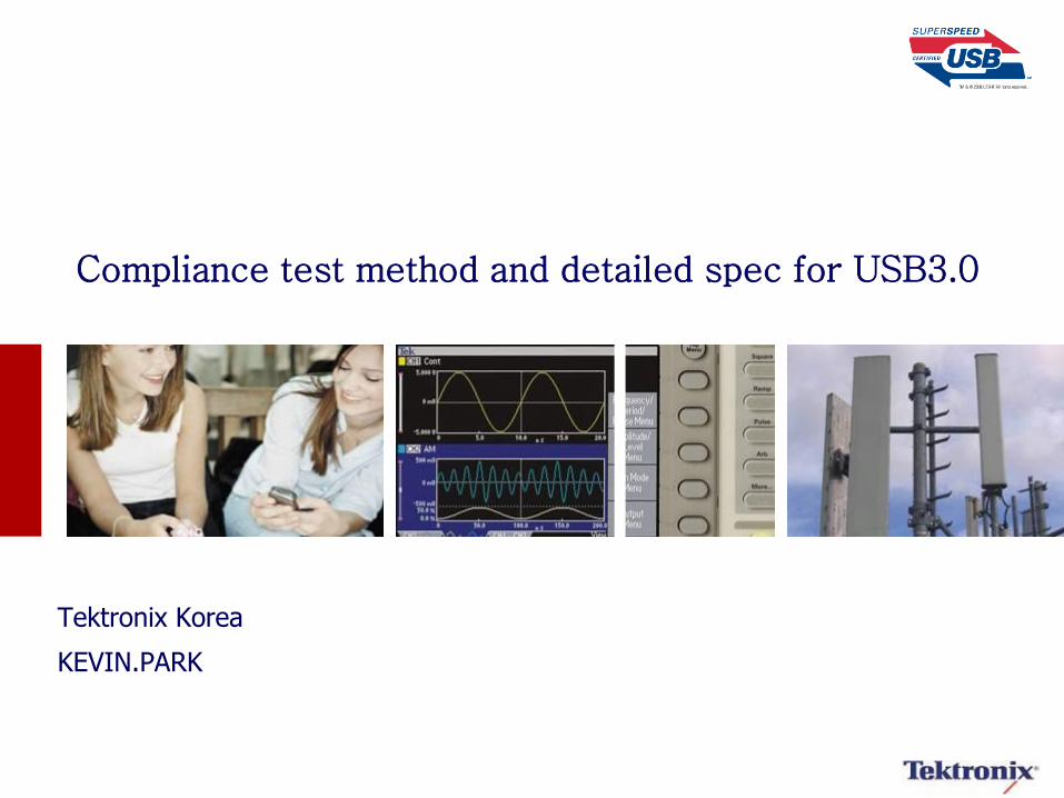
Differences from USB2.0
High-Speed – 480MT/s
– No-SSC
– 2 wires for signaling
• Tx and Rx use the same wire
• 1 bi-directional link
– DC coupled bus
– NRZ encoding
SuperSpeed – 5.0GT/s (10X speed increase)
– SSC is required
– Equalization/CTLE are required
– 4 wires for signaling
• 2 for Tx and 2 for Rx
• Each Uni-directional
– AC Coupled bus
– 8b/10b Encoded
Source: USB-IF
3 2013/10/16
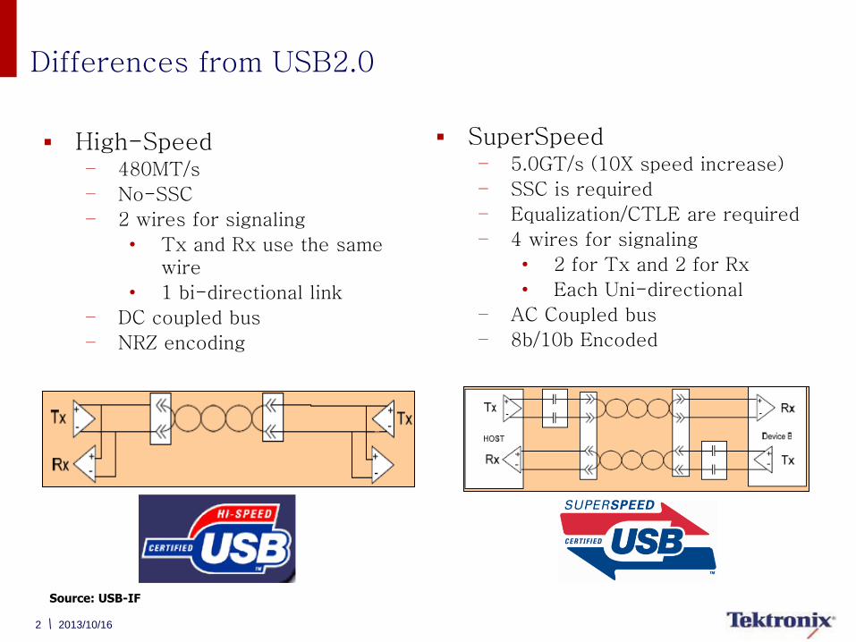
USB 3.0 Key Considerations – Long Channel
Channel characteristics
– 2” ~ 12” Host channel
– 1” ~ 6” Device channel
– 0m ~ 3m Cable
Cause Frequency dependent loss (ISI) and Crosstalk
Close the 5Gb/s eye
Source: USB DevCon
4 2013/10/16
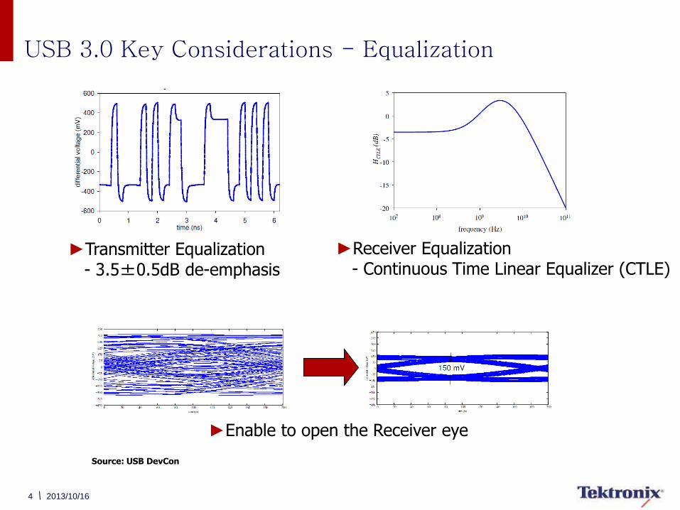
USB 3.0 Key Considerations - Equalization
Source: USB DevCon
►Transmitter Equalization - 3.5±0.5dB de-emphasis
►Receiver Equalization - Continuous Time Linear Equalizer (CTLE)
►Enable to open the Receiver eye
5
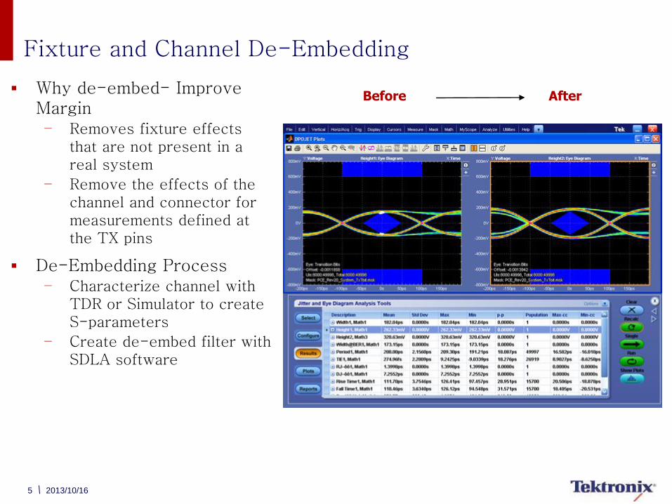
Fixture and Channel De-Embedding
Why de-embed- Improve Margin – Removes fixture effects
that are not present in a real system
– Remove the effects of the channel and connector for measurements defined at the TX pins
De-Embedding Process – Characterize channel with
TDR or Simulator to create S-parameters
– Create de-embed filter with SDLA software
Before After
2013/10/16
6
Channel Embedding
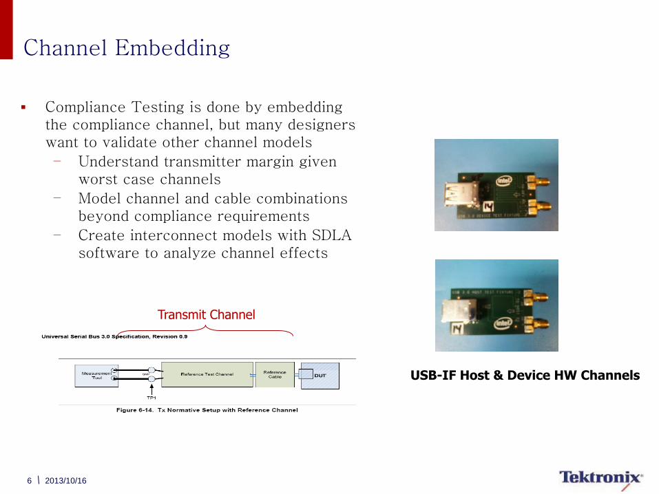
Compliance Testing is done by embedding the compliance channel, but many designers want to validate other channel models
– Understand transmitter margin given worst case channels
– Model channel and cable combinations beyond compliance requirements
– Create interconnect models with SDLA software to analyze channel effects
Transmit Channel
USB-IF Host & Device HW Channels
2013/10/16
7
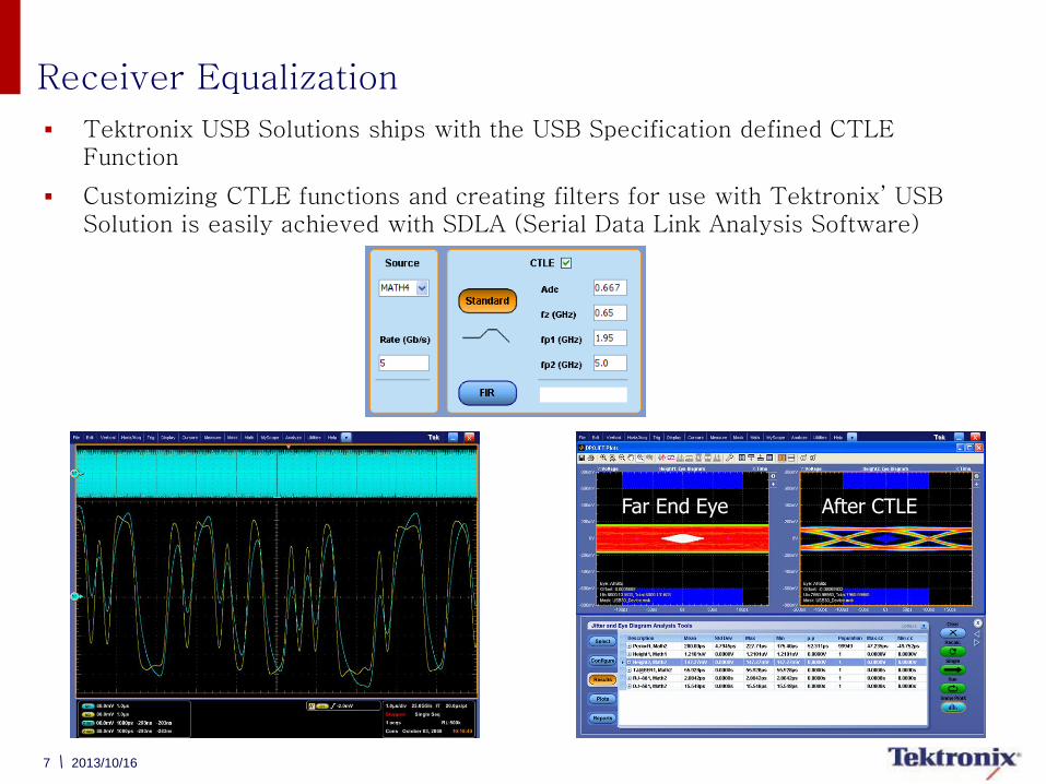
Receiver Equalization
Tektronix USB Solutions ships with the USB Specification defined CTLE Function
Customizing CTLE functions and creating filters for use with Tektronix’ USB Solution is easily achieved with SDLA (Serial Data Link Analysis Software)
Far End Eye After CTLE
2013/10/16
8 2013/10/16
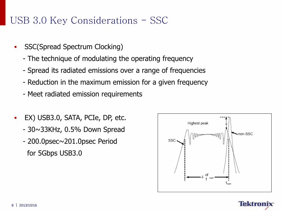
SSC(Spread Spectrum Clocking)
- The technique of modulating the operating frequency
- Spread its radiated emissions over a range of frequencies
- Reduction in the maximum emission for a given frequency
- Meet radiated emission requirements
EX) USB3.0, SATA, PCIe, DP, etc.
- 30~33KHz, 0.5% Down Spread
- 200.0psec~201.0psec Period
for 5Gbps USB3.0
USB 3.0 Key Considerations - SSC
9 2013/10/16
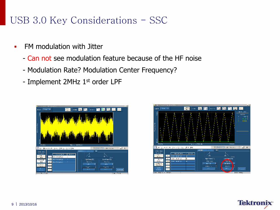
FM modulation with Jitter
- Can not see modulation feature because of the HF noise
- Modulation Rate? Modulation Center Frequency?
- Implement 2MHz 1st order LPF
USB 3.0 Key Considerations - SSC
10 2013/10/16
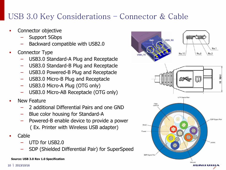
USB 3.0 Key Considerations – Connector & Cable
Connector objective
– Support 5Gbps
– Backward compatible with USB2.0
Connector Type
– USB3.0 Standard-A Plug and Receptacle
– USB3.0 Standard-B Plug and Receptacle
– USB3.0 Powered-B Plug and Receptacle
– USB3.0 Micro-B Plug and Receptacle
– USB3.0 Micro-A Plug (OTG only)
– USB3.0 Micro-AB Receptacle (OTG only)
New Feature
– 2 additional Differential Pairs and one GND
– Blue color housing for Standard-A
– Powered-B enable device to provide a power
( Ex. Printer with Wireless USB adapter)
Cable
– UTD for USB2.0
– SDP (Shielded Differential Pair) for SuperSpeed
Source: USB 3.0 Rev 1.0 Specification
11 2013/10/16
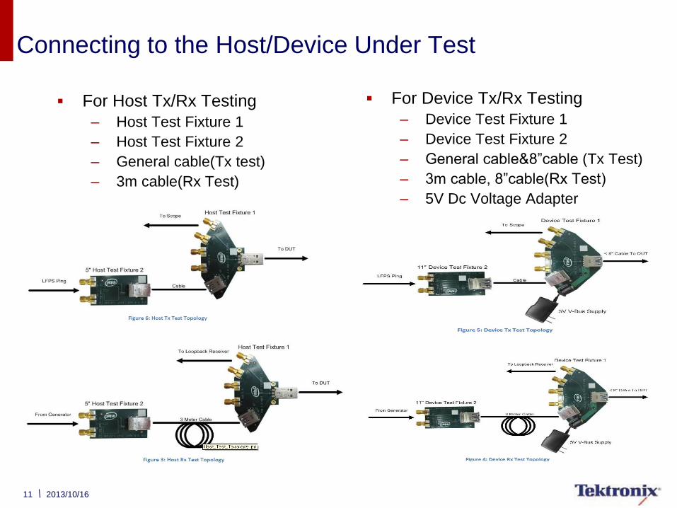
Connecting to the Host/Device Under Test
For Host Tx/Rx Testing
– Host Test Fixture 1
– Host Test Fixture 2
– General cable(Tx test)
– 3m cable(Rx Test)
For Device Tx/Rx Testing
– Device Test Fixture 1
– Device Test Fixture 2
– General cable&8”cable (Tx Test)
– 3m cable, 8”cable(Rx Test)
– 5V Dc Voltage Adapter
12 2013/10/16
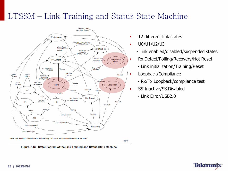
LTSSM – Link Training and Status State Machine
12 different link states
U0/U1/U2/U3
- Link enabled/disabled/suspended states
Rx.Detect/Polling/Recovery/Hot Reset
- Link initialization/Training/Reset
Loopback/Compliance
- Rx/Tx Loopback/compliance test
• SS.Inactive/SS.Disabled
- Link Error/USB2.0
13 2013/10/16
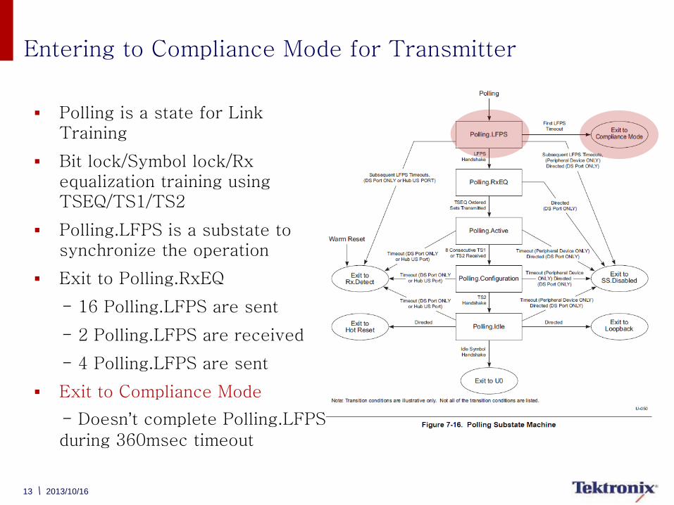
Entering to Compliance Mode for Transmitter
Polling is a state for Link Training
Bit lock/Symbol lock/Rx equalization training using TSEQ/TS1/TS2
Polling.LFPS is a substate to synchronize the operation
Exit to Polling.RxEQ
- 16 Polling.LFPS are sent
- 2 Polling.LFPS are received
- 4 Polling.LFPS are sent
Exit to Compliance Mode
- Doesn’t complete Polling.LFPS
during 360msec timeout
14 2013/10/16
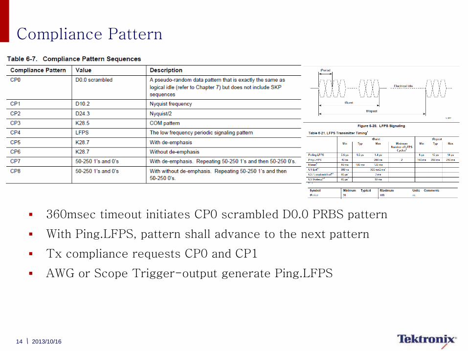
Compliance Pattern
360msec timeout initiates CP0 scrambled D0.0 PRBS pattern
With Ping.LFPS, pattern shall advance to the next pattern
Tx compliance requests CP0 and CP1
AWG or Scope Trigger-output generate Ping.LFPS
15 2013/10/16
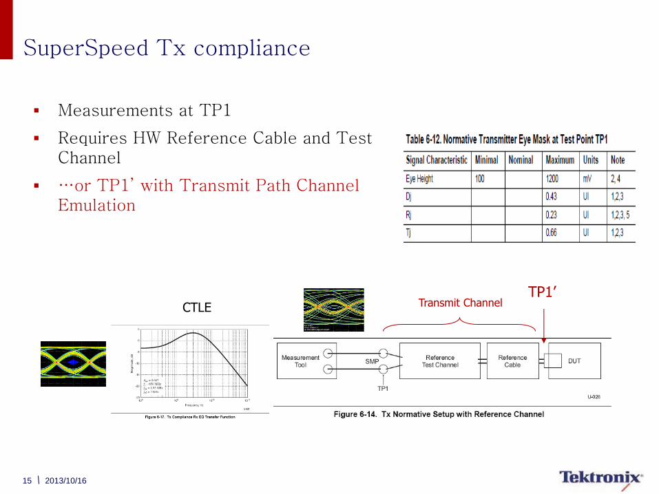
SuperSpeed Tx compliance
Measurements at TP1
Requires HW Reference Cable and Test Channel
…or TP1’ with Transmit Path Channel Emulation
Transmit Channel TP1’
CTLE
16 2013/10/16
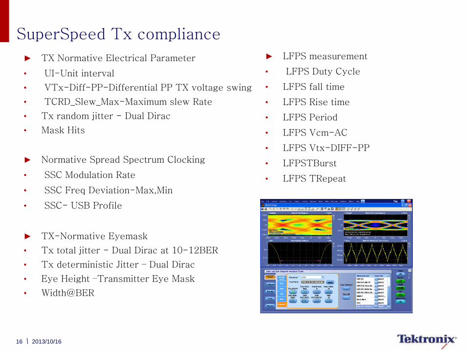
SuperSpeed Tx compliance
► TX Normative Electrical Parameter
• UI-Unit interval
• VTx-Diff-PP-Differential PP TX voltage swing
• TCRD_Slew_Max-Maximum slew Rate
• Tx random jitter - Dual Dirac
• Mask Hits
► Normative Spread Spectrum Clocking
• SSC Modulation Rate
• SSC Freq Deviation-Max,Min
• SSC- USB Profile
► TX-Normative Eyemask
• Tx total jitter - Dual Dirac at 10-12BER
• Tx deterministic Jitter – Dual Dirac
• Eye Height –Transmitter Eye Mask
• Width@BER
► LFPS measurement
• LFPS Duty Cycle
• LFPS fall time
• LFPS Rise time
• LFPS Period
• LFPS Vcm-AC
• LFPS Vtx-DIFF-PP
• LFPSTBurst
• LFPS TRepeat
17 2013/10/16
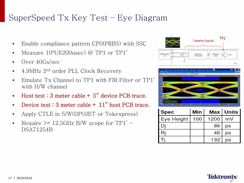
SuperSpeed Tx Key Test – Eye Diagram
Enable compliance pattern CP0(PRBS) with SSC
Measure 106UI(200usec) @ TP1 or TP1’
Over 40Gs/sec
4.9MHz 2nd order PLL Clock Recovery
Emulate Tx Channel to TP1 with FIR Filter or TP1’ with H/W channel
Host test : 3 meter cable + 5” device PCB trace.
Device test : 3 meter cable + 11” host PCB trace.
Apply CTLE in S/W(DPOJET or Tekexpress)
Require >= 12.5GHz B/W scope for TP1’ - DSA71254B

18 2013/10/16
SuperSpeed Tx Key Test – Dj, Rj & Tj @ BER
Enable compliance pattern CP0(PRBS) with SSC
Change compliance pattern to CP1 with SSC
Measure 106UI(200usec) @ TP1 or TP1’
Over 40Gs/sec
4.9MHz 2nd order PLL Clock Recovery
Emulate Tx Channel to TP1 with FIR Filter or TP1’ with H/W channel
Host test : 3 meter cable + 5” device PCB trace.
Device test : 3 meter cable + 11” host PCB trace.
Apply CTLE in S/W(DPOJET or Tekexpress)
Dj from CP0 & Rj from CP1
Calculate T j @BER E-12 using Dual-Dirac method
• Q is 7 when BER=10-12
Source: USB 3.0 Rev 1.0 Specification
19 2013/10/16
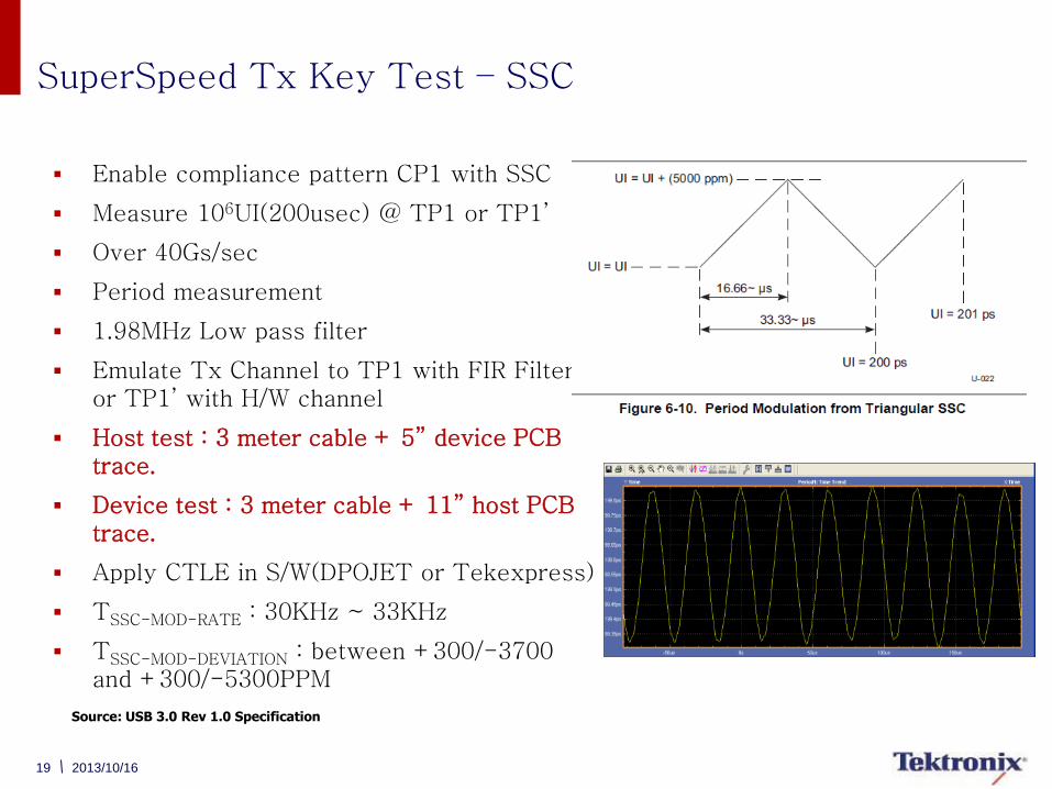
SuperSpeed Tx Key Test – SSC
Enable compliance pattern CP1 with SSC
Measure 106UI(200usec) @ TP1 or TP1’
Over 40Gs/sec
Period measurement
1.98MHz Low pass filter
Emulate Tx Channel to TP1 with FIR Filter or TP1’ with H/W channel
Host test : 3 meter cable + 5” device PCB trace.
Device test : 3 meter cable + 11” host PCB trace.
Apply CTLE in S/W(DPOJET or Tekexpress)
TSSC-MOD-RATE : 30KHz ~ 33KHz
TSSC-MOD-DEVIATION : between +300/-3700 and +300/-5300PPM
Source: USB 3.0 Rev 1.0 Specification
20 2013/10/16
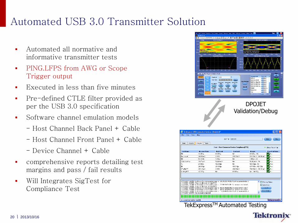
Automated USB 3.0 Transmitter Solution
Automated all normative and informative transmitter tests
PING.LFPS from AWG or Scope Trigger output
Executed in less than five minutes
Pre-defined CTLE filter provided as per the USB 3.0 specification
Software channel emulation models
- Host Channel Back Panel + Cable
- Host Channel Front Panel + Cable
- Device Channel + Cable
comprehensive reports detailing test margins and pass / fail results
Will Integrates SigTest for Compliance Test
TekExpressTM Automated Testing
DPOJET Validation/Debug
21
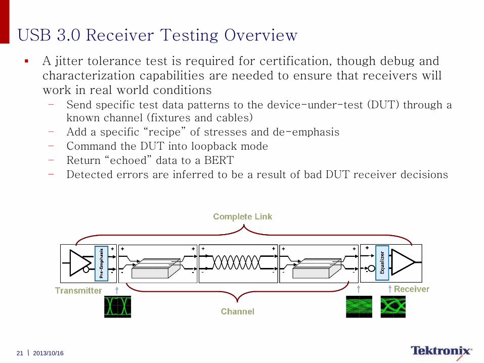
USB 3.0 Receiver Testing Overview
A jitter tolerance test is required for certification, though debug and characterization capabilities are needed to ensure that receivers will work in real world conditions – Send specific test data patterns to the device-under-test (DUT) through a
known channel (fixtures and cables)
– Add a specific “recipe” of stresses and de-emphasis
– Command the DUT into loopback mode
– Return “echoed” data to a BERT
– Detected errors are inferred to be a result of bad DUT receiver decisions
2013/10/16
22 2013/10/16
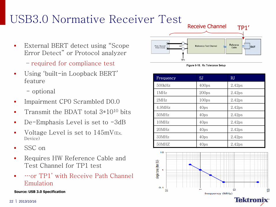
External BERT detect using “Scope Error Detect” or Protocol analyzer
– required for compliance test
Using ‘built-in Loopback BERT’ feature
- optional
Impairment CP0 Scrambled D0.0
Transmit the BDAT total 3*1010 bits
De-Emphasis Level is set to -3dB
Voltage Level is set to 145mV(Ex.
Device)
SSC on
Requires HW Reference Cable and Test Channel for TP1 test
…or TP1’ with Receive Path Channel Emulation
Receive Channel
Source: USB 3.0 Specification
TP1’
Frequency SJ RJ
500kHz 400ps 2.42ps
1MHz 200ps 2.42ps
2MHz 100ps 2.42ps
4.9MHz 40ps 2.42ps
50MHz 40ps 2.42ps
10MHz 40ps 2.42ps
20MHz 40ps 2.42ps
33MHz 40ps 2.42ps
50MHZ 40ps 2.42ps
USB3.0 Normative Receiver Test
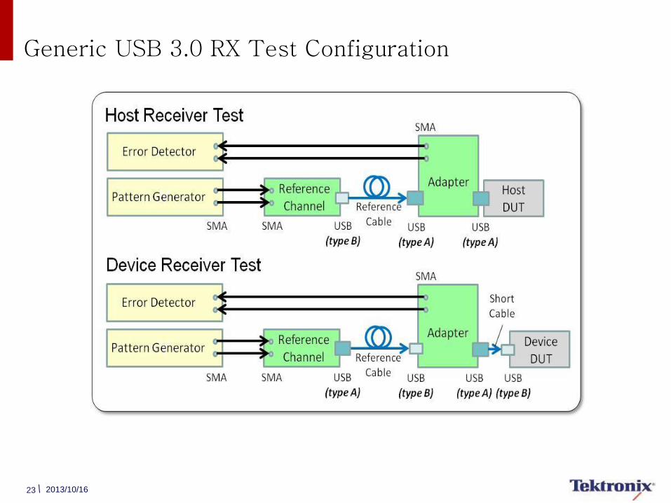
Generic USB 3.0 RX Test Configuration
23 2013/10/16
24 2013/10/16
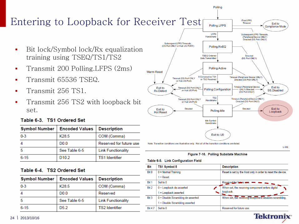
Entering to Loopback for Receiver Test
Bit lock/Symbol lock/Rx equalization training using TSEQ/TS1/TS2
Transmit 200 Polling.LFPS (2ms)
Transmit 65536 TSEQ.
Transmit 256 TS1.
Transmit 256 TS2 with loopback bit set.
25
Two Solutions for USB 3.0 Receiver Testing BERTScope BSA85C and AWG7122C
Tektronix has the right solution to meet your needs
– Both provide fully automated Receiver Compliance and Jitter Tolerance Testing
– Both offer advanced impairments to debug problems caused by SSC or other anomalies
– Both support a wide range of HSS Standards
– Both support asynchronous clocking (SKP order set rejection)
BERTScope
– Performance that you need up to 26Gb/s for next generations standards including DisplayPort 1.2, SATA/SAS, 10G KR, PCI Express 3.0
– Impairments can be changed on the fly to see the effect of increasing or reducing jitter
– Debug and analysis tools enable quick identification of RX errors
– True BER measurements
Arbitrary Waveform Generator
– Common platform for MIPI, HDMI, USB 3.0, and SATA
– Only solution available that provides a common setup between transmitter and receiver testing without the need of RF switches and additional setup complexity
– Easily apply sparameter models to verify designs under different channel conditions without the need of physical ISI channels
– Generate SJ > 1Ghz to debug elusive problems caused by other system clocks
2013/10/16
26 2013/10/16
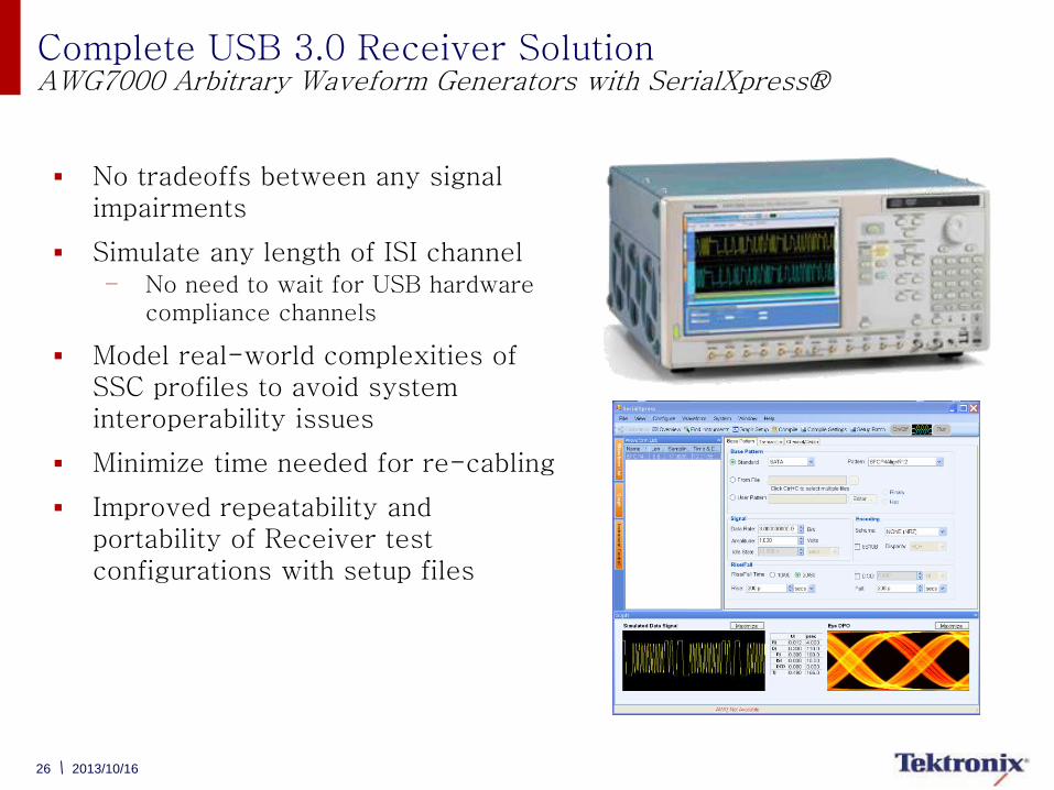
Complete USB 3.0 Receiver Solution AWG7000 Arbitrary Waveform Generators with SerialXpress®
No tradeoffs between any signal impairments
Simulate any length of ISI channel – No need to wait for USB hardware
compliance channels
Model real-world complexities of SSC profiles to avoid system interoperability issues
Minimize time needed for re-cabling
Improved repeatability and portability of Receiver test configurations with setup files
27 2013/10/16
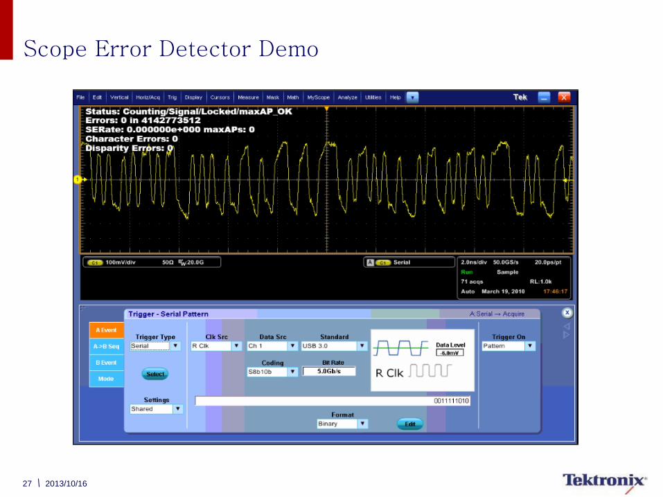
Scope Error Detector Demo
28 2013/10/16
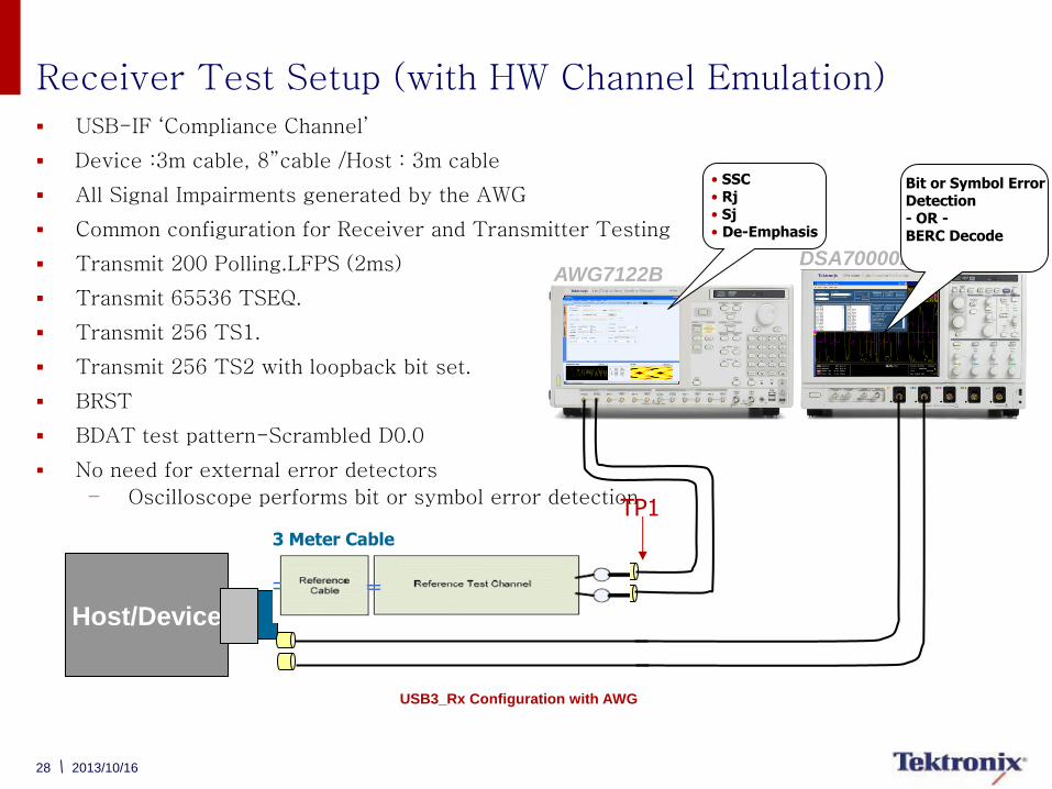
3 Meter Cable
Receiver Test Setup (with HW Channel Emulation) USB-IF ‘Compliance Channel’
Device :3m cable, 8”cable /Host : 3m cable
All Signal Impairments generated by the AWG
Common configuration for Receiver and Transmitter Testing
Transmit 200 Polling.LFPS (2ms)
Transmit 65536 TSEQ.
Transmit 256 TS1.
Transmit 256 TS2 with loopback bit set.
BRST
BDAT test pattern-Scrambled D0.0
No need for external error detectors
– Oscilloscope performs bit or symbol error detection
TP1
USB3_Rx Configuration with AWG
Host/Device
AWG7122B DSA70000B
• SSC • Rj • Sj • De-Emphasis
Bit or Symbol Error Detection - OR - BERC Decode
29 2013/10/16
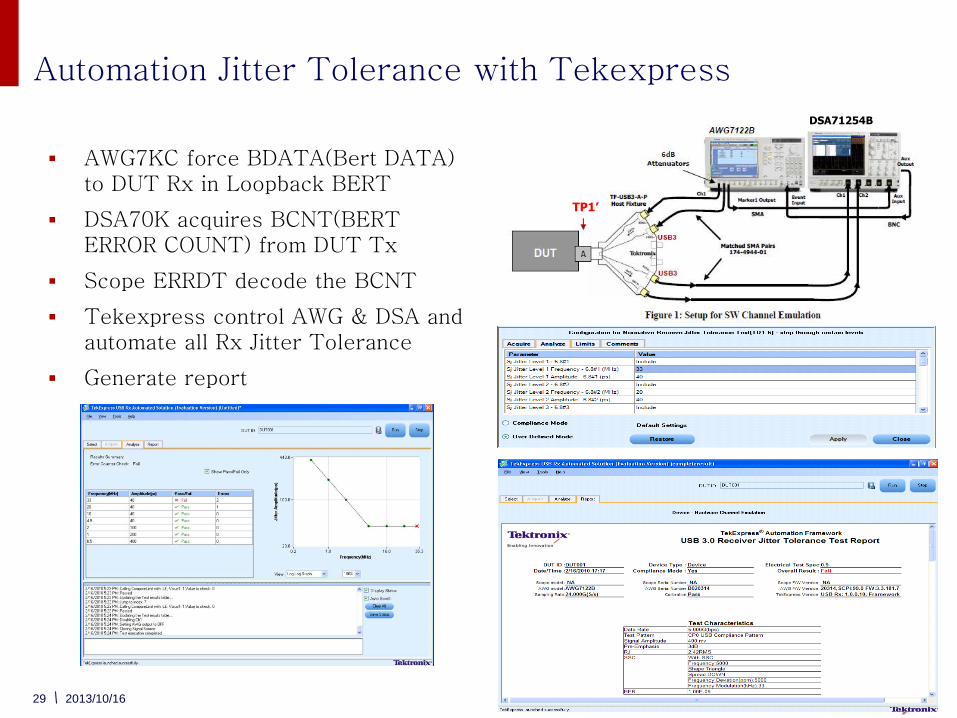
Automation Jitter Tolerance with Tekexpress
AWG7KC force BDATA(Bert DATA) to DUT Rx in Loopback BERT
DSA70K acquires BCNT(BERT ERROR COUNT) from DUT Tx
Scope ERRDT decode the BCNT
Tekexpress control AWG & DSA and automate all Rx Jitter Tolerance
Generate report
DSA71254B
TP1’
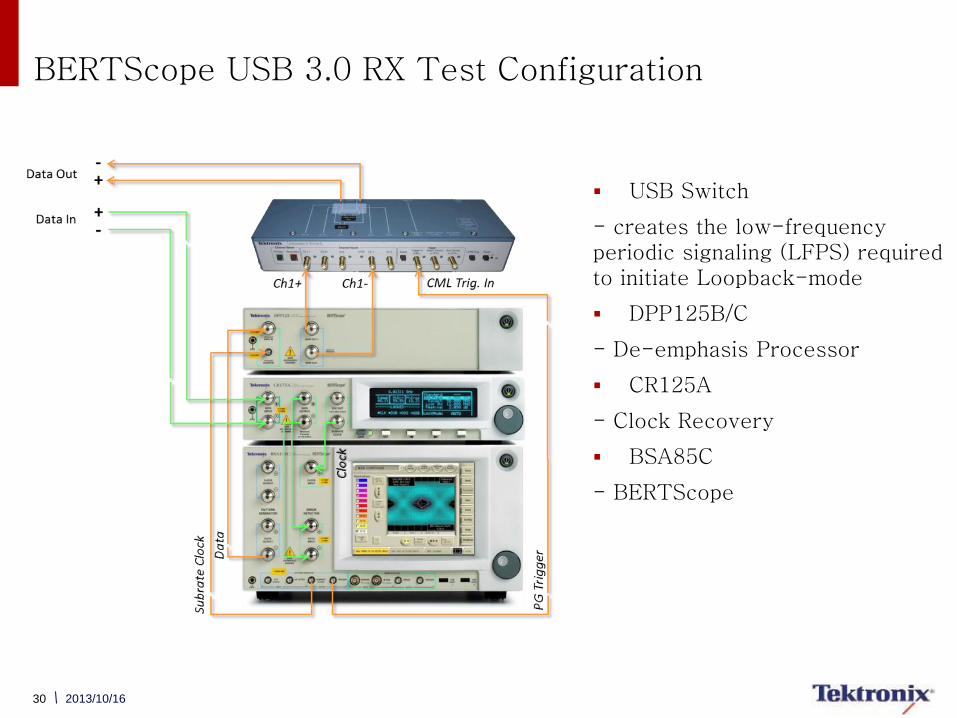
BERTScope USB 3.0 RX Test Configuration
30 2013/10/16
USB Switch
- creates the low-frequency periodic signaling (LFPS) required to initiate Loopback-mode
DPP125B/C
- De-emphasis Processor
CR125A
- Clock Recovery
BSA85C
- BERTScope
31
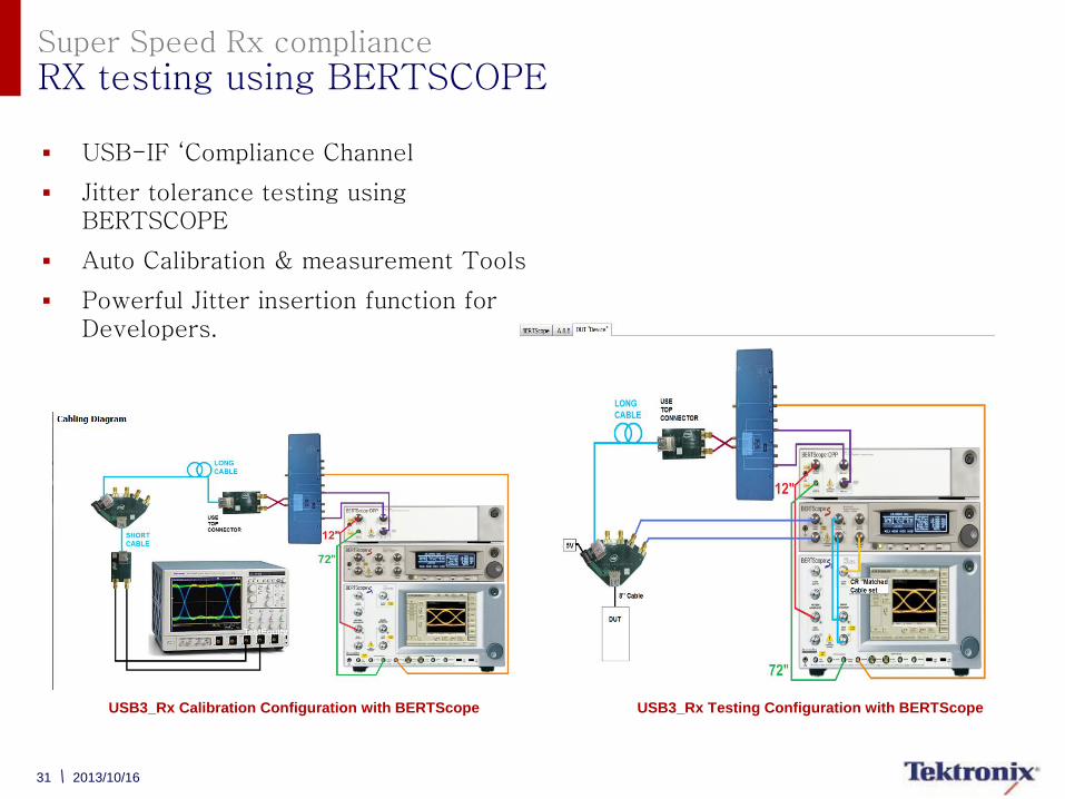
Super Speed Rx compliance
RX testing using BERTSCOPE
USB-IF ‘Compliance Channel
Jitter tolerance testing using BERTSCOPE
Auto Calibration & measurement Tools
Powerful Jitter insertion function for Developers.
2013/10/16
USB3_Rx Testing Configuration with BERTScope USB3_Rx Calibration Configuration with BERTScope
32 2013/10/16
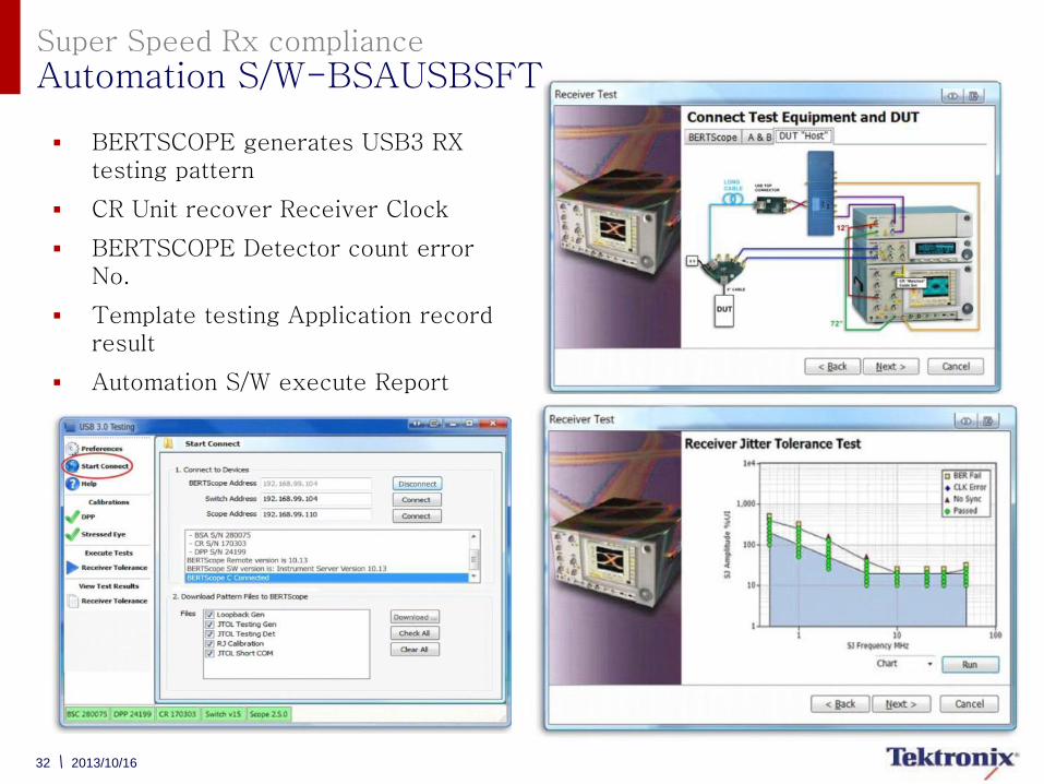
Super Speed Rx compliance
Automation S/W-BSAUSBSFT
BERTSCOPE generates USB3 RX testing pattern
CR Unit recover Receiver Clock
BERTSCOPE Detector count error No.
Template testing Application record result
Automation S/W execute Report
33 2013/10/16
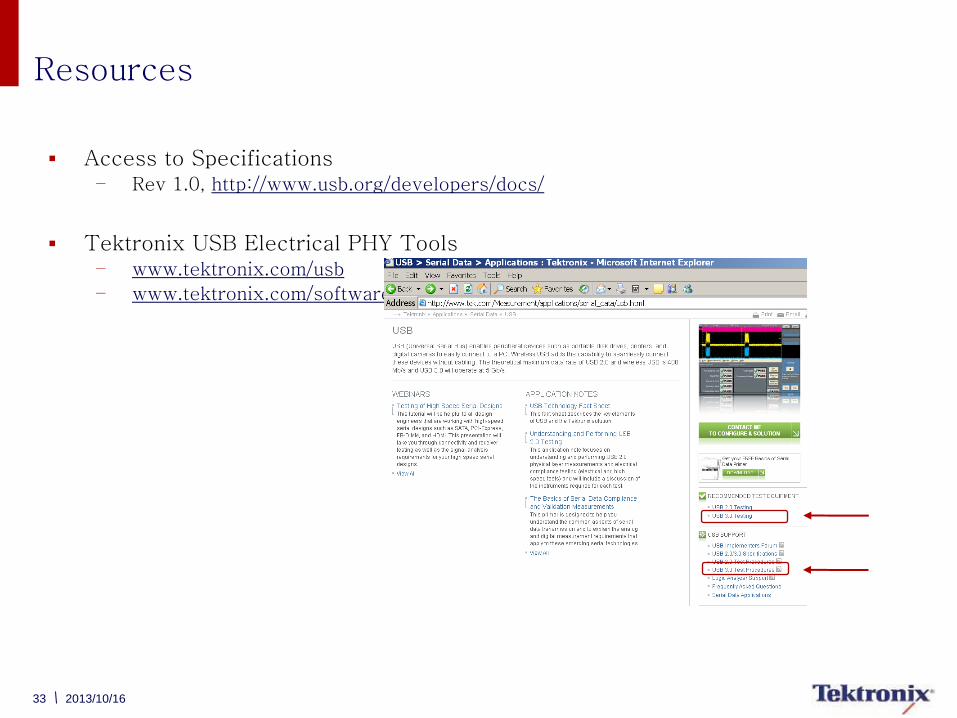
Resources
Access to Specifications – Rev 1.0, http://www.usb.org/developers/docs/
Tektronix USB Electrical PHY Tools – www.tektronix.com/usb
– www.tektronix.com/software