Embed Size (px)
Citation preview
BR-00730
N COMPOSITEHULLLFORAND* n AMPHIBIOUS VEHICLE
Design, Fabrication, and Testing of aComposite Hull for a Tracked Amphibious Vehicle
Phase I and 11 Final Report
DTICIAugust 1988 ZLECT
Period Covered: FEB 2 29830 December 1983 -31 October 1986 SL 22 98 1
I Prepared under Contract N00167-84-C-0023 for:-
3 David Taylor Research CenterBethesda, Maryland 20084
I Prepared by:
Martin Marietta £orporaioer-I Aero & Naval Systems103 Chesapeake Park Plaza w umNsI W IBaltimore, Maryland 21220 Approved fpr pubic r.1.aso ,
s doc menD cottion bj to he I erna na
witho first obtaining export license.
Inlde ths oice with anyrepodcdpr this docu
PaFA*:AugusT04 .0th&cqests, o iiocu ut f o c
I7
UNCLASSIFIEDSECuRITY CLASSIFICATION OF THIS PAR
REPORT DOCUMENTATION PAGE
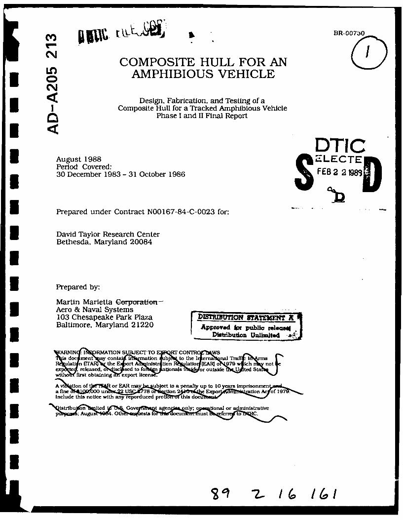
la REPORT SECURITY CLASSIFICATION lb RESTRICTIVE MARKINGSUNCLASSIFIED NONE
2a SECURITY CLASSIFICATION AUTHORITY 3 DISTRIBUTION/AVAILABILITY OF REPORT
2b DECLASSIFICATION/DOWNGRADING SCHEDULE APPROVED FOR PUBLIC RELEASE:DISTRIBUTION UNLIMITED
4 PERFORMING ORGANIZATION REPORT NUMBER(S) S MONITORING ORGANIZATION REPORT NUMBER(S)
BR-00730 DTRC-SSID-CR-19-89
6a NAME OF PERFORMING ORGANIZATION 6b OFFICE SYMBOL 7a NAME OF MONITORING ORGANIZATION
Martin Marietta Aero & Naval (if applicable)
Systems David Taylor Research Center (DTRC)
6c ADDRESS (City, State, and ZIPCode) 7b ADDRESS (City. State, and ZIP Code)
103 Chesapeake Park Plaza Bethesda, MD 20084-5000Baltimore, MD 21220
Ba NAME OF FUNDINGiSPONSORING 8o OFFICE SYMBOL 9. PROCUREMENT INSTRUMENT IDENTIFICATION NUMBERORGANIZATION (If applicable)
DAVID TAYLOR RESEARCH CENTER 1240 N00167-84-C-0023
8c ALJDRtSS(Cty. State, and ZIPCode) 10 SOURCE OF FUNDING NUMBERS
PROGRAM PROJECT TASK WORK UNITELEMENT NO NO NO ACCESSION NO
62543N CF43455 )N978568
11 TITLE (Include Security Classification)
COMPOSITE HULL FOR AN AMPHIBIOUS VEHICLE
2 P RSONAL AUTHOR(S)R. C. CURLEY
13a TYPE OF REPORT 13b TIME COVERED 514 DATEOFREPORT(Year'MonthDay) S PAGE COUNTFINALFROM 831 0OOOL12/34 88/8 I 84
16 SUPPLEMENTARY NOTATION
17 COSATI CODES 18 SUBJECT TERMS (Continue on reverse if necessary and identify by block number)
_FIELD GROUP SUBGROOP -"Armor, Composites, Design, Development, Lightweight Veh le.
''3 ASTRACT (Continue on reverse if necessary and identify by block number)In response to a Marine Corps request for a lightweight composite hull for amphibious
vehicles, a glass reinforced plastic (GRP) hull for an M113AL armored personnel carrier hasbeen designed, fabricated, and tested under phases I and II of a David Taylor Research
Center development program.
The one-piece, molded hull of epoxy E-glass woven laminate is joined to a welded aluminunlower hull to provide a lightweight, buoyant vehicle, armored on the sides, front and rearby 4-inch square ceramic tiles protected by thin aluminum sheet. Thickness of the compositematerial is 0.75 inch at the sides and 1.25 inch at the roof.
Design efforts were marked by a number of key developmental activities including structual design, stress analysis and material evaluation as well as fabrication of the hull. Inaddition to delivering test panels to DTRC, the contractor also conducted repairability
20 .)'S!Pi4jT'ONj 'AVAILABILITY OF ABSTRACT 21 ABSTRACT SECURITY CLASSIFICATIONUJ'LASSI FEDjUNLIMITED [0 SAME AS PPT -DTIC UERS UNCLASSIFIED
. 'a P 4A'E OF RESPONSIBLE INDIVIDUAL 22b TELEPHONE (Include Area Code) 22c OFFICE SYMBOL
RICHARD SWANEK (202) 227-1852 1240
DO FORM 1473, Rd .AAR g AOO pdit,_n if r -, 'J -- .o'austed SECURITY CLASSIFCATiON OF THIS PAGEAl other ed.to is a e oosofeze UNCLASSIFIED
UNCLASSIFIEDSECURITY CLASSIFICATION OF THIS PAGE
and fabrication methods studies and provided production cost estimates and vehicle weight
and flotation stability calculations.
A completed vehicle was delivered to the Marine Corps for field testing. The vehicle
went through one year of rigorous field tests with no observable degradation of the
composite hull.
UNCLASSIFIEDSECURIT ASSIFIjIOrF THIS P1EG I
nn ~~8 Z _m ) T 6lNIII1lN~
IBR-00730
I COMPOSITE HULL FOR ANAMPHIBIOUS VEHICLE
I Design, Fabrication, and Testing of aComposite Hull for a Tracked Amphibious Vehicle
Phase I and II Final Report
IAugust 1988
Period Covered:
30 December 1983 - 31 October 1986IPrepared under Contract N00167-84-C-0023 for:
I David Taylor Research CenterBethesda, Maryland 20084IPrepared by:
Martin Marietta CorporationAero & Naval Systems103 Chesapeake Park PlazaBaltimore, Maryland 21220
I -
Robert C. Curley T J IrProgram Manager i. "
Distribution Statement A is correct for thisreport. A,, i, ';v cjeesPer Mr. Richard Swanek, DTRC/Code 1240
I1AI
PREFACE
i This final report covers work performed by Martin Marietta Corporation,Aero & Naval Systems under Phases I and II of ContractN00167-84-C-0023, "Design Fabrication and Testing of a Composite Hullfor a Tracked Amphibious Vehicle." It covers work performed from30 December 1983 through 31 October 1986. The contracting officer'stechnical representative (COTR) for the program was Mr. Richard A. Swanek,Marine Corps Program Office, David Taylor Research Center, Bethesda,Maryland.
I Mr. R.C. Curley was the Martin Marietta program manager responsible forplanning and conducting all respects of the program.
i Principal contributors to the Martin Marietta activities described inthis report were: R.L. Bernstein, and E.L. May, C.S. Stoddard - structuraldesign; R.M. Hill and A.P. DeCicco - Tooling, and C.T. Kogut, B.L. Rosenquist,R.D. Hoskins and R.G. Schmitt - Fabrication and Assembly.
IIIIiIiiI
ii
II
ABSTRACT
In response to a Marine Corps quest for a lightweight composite hull foramphibious vehicles, a glass reinforced plastic (GRP) hull for an M1 13A1armored personnel carrier has been designed and fabricated under PhasesI and II of a David Taylor Research Center (DTRC) development program.
The one-piece, molded hull of epoxy E-glass woven roving laminateis joined to a welded aluminum lower hull to provide a lightweight, buoyantvehicle, armored on the sides, front and rear by 4-inch square ceramictiles protected by thin aluminum sheet. Thickness of the compositematerial is 0.75 inch at the sides and 1.25 inch at the roof.
Design efforts were marked by a number of key developmental activitiesincluding structural design, stress analysis and material evaluation aswell as fabrication of the hull. In addition to delivering test panelsto DTRC, the contractor also conducted repairability and fabricationmethods studies and provided production cost estimates and vehicle weightand flotation stability calculations.
IA completed vehicle was delivered to the Marine Corps for field testing.The vehicle went through one year of rigorous field testing withoutany detectable degradation of the composite hull.
IIIIIII
IoIl
I CONTENTS
1.0 INTRODUCTION . . . . . . . . . . . . . . . . . . . . . . . .
2.0 HULL DESIGN ................................. 3
3.0 REPAIRABILITY STUDY ..... ................. .... 17
4.0 STRUCTURAL ANALYSIS ...................................... .. 26
5.0 MATERIALS AND PROCESS ..... .................... .. 47I6.0 FABRICATION ................................ .. 54
7.0 WEIGHT, CENTER OF GRAVITY AND CENTER OF BUOYANCY ........ 70
1 8.0 MANUFACTURING COST STUDY .... ................... ... 78
9.0 TEST RESULTS .............................. .. 83
10.0 RESEARCH AND DEVELOPMENT .... ................... ... 84
11.0 CONCLUSIONS AND RECOMMENDATIONS .. ............... .. 85
IIUIII
ivI
II
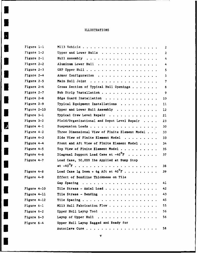
ILLUSTRATIONSIFigure 1-1 M113 Vehicle .......... .................... 2
Figure 1-2 Upper and Lower Hulls ....... ............... 2
Figure 2-1 Hull Assembly ......... ................... 4
Figure 2-2 Aluminum Lower Hull ........ ................ 4
Figure 2-3 GRP Upper Hull ......... ................... 5
Figure 2-4 Armor Configuration ........ ................ 5
Figure 2-5 Main Hull Joint ......... .................. 7
Figure 2-6 Cross Section of Typical Hull Openings.......8
Figure 2-7 Rub Strip Installation ....... ............... 9
Figure 2-8 Edge Guard Installation ....... .............. 10
Figure 2-9 Typical Equipment Installations .. .......... . I.11
Figure 2-10 Upper and Lower Hull Assembly .. ........... ... 12
Figure 3-1 Typical Crew Level Repair .... ............. ... 21
Figure 3-2 Field/Organizational and Depot Level Repair . . .. 23
Figure 4-1 Suspension Loads ...... .................. .. 30
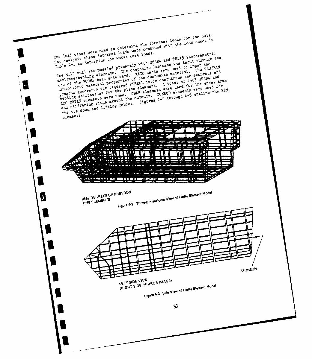
Figure 4-2 Three Dimensional View of Finite Element Model . . 33
Figure 4-3 Side View of Finite Element Model ......... 33
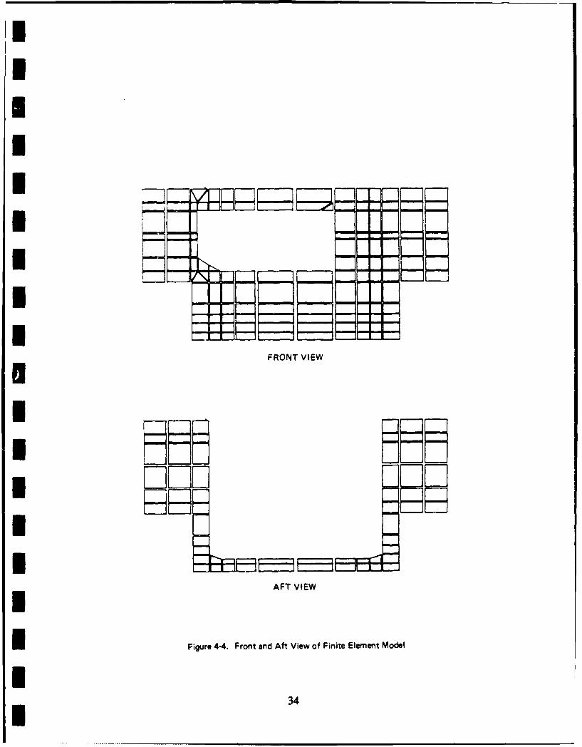
Figure 4-4 Front and Aft View of Finite Element Model .. ..... 34
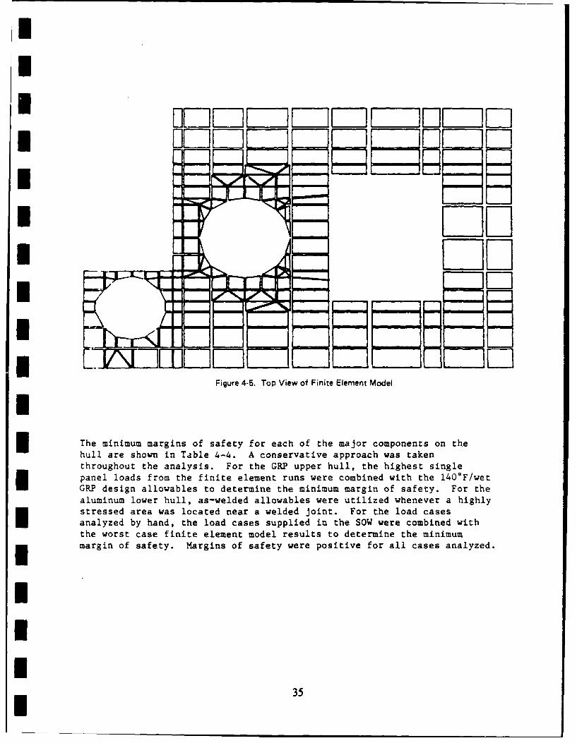
Figure 4-5 Top View of Finite Element Model .. .......... .. 35
Figure 4-6 Diagonal Support Load Case at -40..F .......... .. 37
Figure 4-7 Load Case, 50,000 lbs Applied at Bump Stop
at -400 F ....... ...................... .... 38
Figure 4-8 Load Case lg Down + 6g Aft at 400.F ......... .... 39
Figure 4-9 Effect of Bondline Thickness on Tile
Gap Spacing ....... .................... .. 41
f Figure 4-10 Tile Stress - Axial Load .... .............. .... 42
Figure 4-11 Tile Stress - Bending .... ............... .... 43
Figure 4-12 Tile Spacing ....... .................... .. 45
Figure 6-1 M113 Hull Fabrication Flow .... ............. ... 55
Figure 6-2 Upper Hull Layup Tool .... ............... .... 56
Figure 6-3 Layup of Upper Hull ..................... .. 56
Figure 6-4 Upper Hull Layup Bagged and Ready for
Autoclave Cure ...... ....................... 58
VI
i
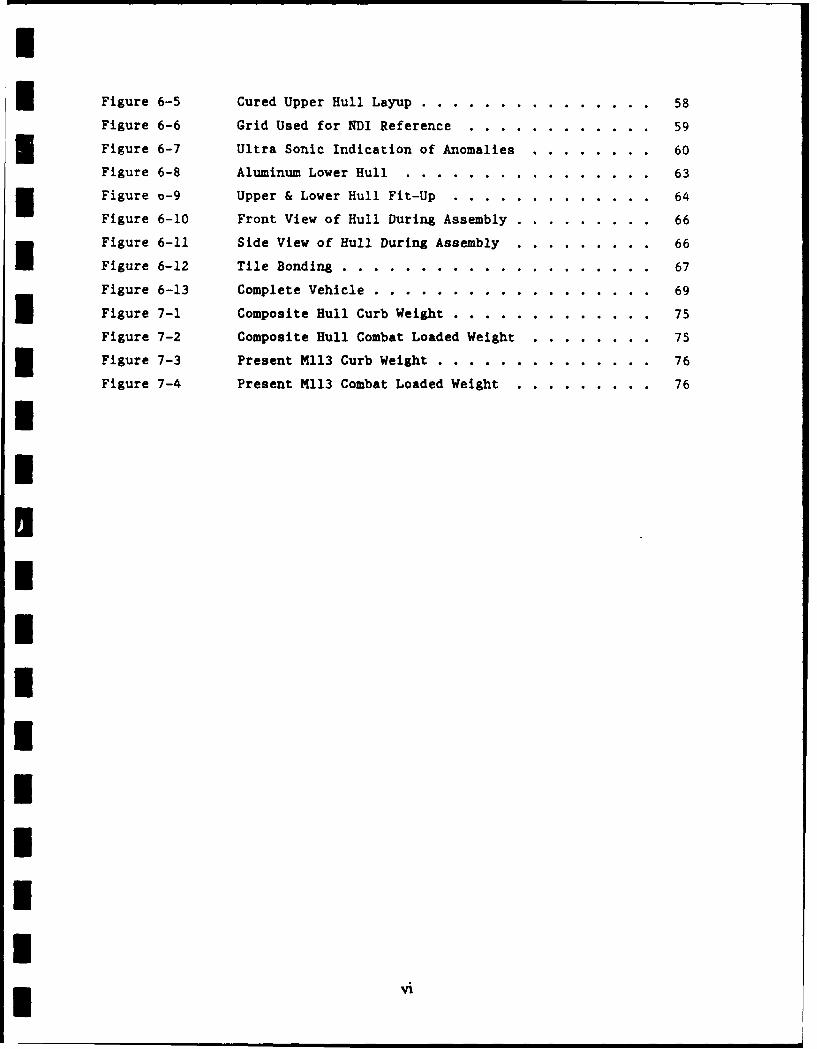
Figure 6-5 Cured Upper Hull Layup ..... .............. ... 58
Figure 6-6 Grid Used for NDI Reference .. ............ ... 59
Figure 6-7 Ultra Sonic Indication of Anomalies ......... .. 60
Figure 6-8 Aluminum Lower Hull ..... ................ ... 63
Figure o-9 Upper & Lower Hull Fit-Up ... ............. ... 64
Figure 6-10 Front View of Hull During Assembly .... ......... 66
Figure 6-11 Side View of Hull During Assembly . ......... .. 66
Figure 6-12 Tile Bonding ...... .................... ... 67
Figure 6-13 Complete Vehicle ...... .................. ... 69
Figure 7-1 Composite Hull Curb Weight .. ............. .... 75
Figure 7-2 Composite Hull Combat Loaded Weight ......... .. 75
Figure 7-3 Present M113 Curb Weight ... .............. ... 76
Figure 7-4 Present M113 Combat Loaded Weight . ......... .. 76
IUIUIIIIIII
I
3 TABLES
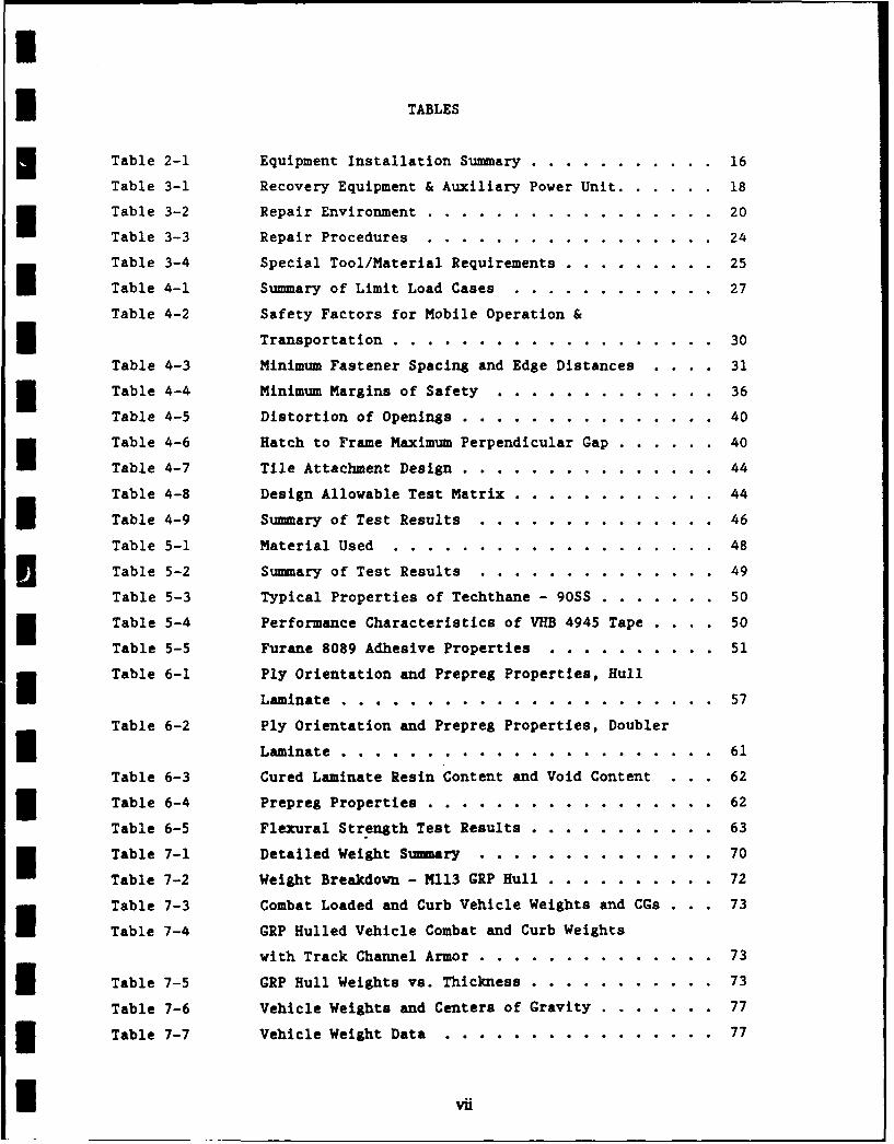
Table 2-1 Equipment Installation Summary ........... 16
Table 3-1 Recovery Equipment & Auxiliary Power Unit ... ...... 18
Table 3-2 Repair Environment ..... ................. .... 20
Table 3-3 Repair Procedures ....................... .. 24
Table 3-4 Special Tool/Material Requirements .. ......... .. 25
Table 4-1 Summary of Limit Load Cases ... ............ .. 27
Table 4-2 Safety Factors for Mobile Operation &
Transportation ......................... .. 30
Table 4-3 Minimum Fastener Spacing and Edge Distances .... 313 Table 4-4 Minimum Margins of Safety ... ............. .... 36
Table 4-5 Distortion of Openings .............. . 40
Table 4-6 Hatch to Frame Maximum Perpendicular Gap ... ...... 40
Table 4-7 Tile Attachment Design .... ............... .... 44
Table 4-8 Design Allowable Test Matrix ... ............ .... 44
Table 4-9 Summary of Test Results ..... .............. .. 46
Table 5-1 Material Used .......................... .. 48
I Table 5-2 Summary of Test Results ..... ................ 49
Table 5-3 Typical Properties of Techthane - 90SS ... ....... 50
Table 5-4 Performance Characteristics of VHB 4945 Tape . ... 50
Table 5-5 Furane 8089 Adhesive Properties ... .......... .. 51
Table 6-1 Ply Orientation and Prepreg Properties, Hull
Laminate .............................. .. 57
Table 6-2 Ply Orientation and Prepreg Properties, Doubler
m Laminate .............................. .. 61
Table 6-3 Cured Laminate Resin Content and Void Content . 62
3 Table 6-4 Prepreg Properties ................. 62
Table 6-5 Flexural Strength Test Results .. ........... .... 63
Table 7-1 Detailed Weight Summary ..... .............. .. 70
Table 7-2 Weight Breakdown - M113 GRP Hull ... .......... .. 72
Table 7-3 Combat Loaded and Curb Vehicle Weights and CGs . . . 73
Table 7-4 GRP Hulled Vehicle Combat and Curb Weights
with Track Channel Armor .... .............. .. 73
3 Table 7-5 GRP Hull Weights vs. Thickness .. ........... ... 73
Table 7-6 Vehicle Weights and Centers of Gravity ... ....... 77
3 Table 7-7 Vehicle Weight Data ...... ................ .. 77
I ,vi
Table 8-1 Production Cost Estimate - 1000 Units .. .. .. ... 79
ITable 8-2 Estimated Labor Cost Summary. .. .. .. .. ....... 8
Table 8-3 Summary of Estimated Materials Cost .. .. .. ..... 81
Table 8-4 Hourly Rate Derivation .. .. .. .. .......... 82
Iif
1.0 INTRODUCTION
The "!rine Corps Programs Office of the David Taylor Research Center(DTRC) presently manages an Exploratory Development program, Marine CorpsSurface Mobility, in which a technology base is being developed for
future Marine Corps amphibious vehicles.
As a part of this program DTRC is pursuing the development of alightweight composite hull for possible use on future amphibiousvehicles. This development program was undertaken to demonstrate thetechnical feasibility of using composite materials for hull constructionand to quantify possible weight and cost savings.
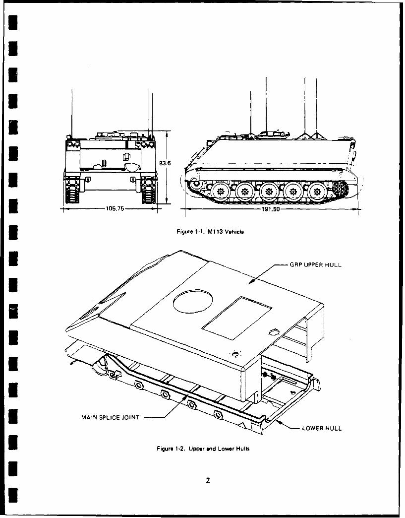
As an initial step in this program, Martin Marietta Aero & Naval Systems,under Phase I of a contract with DTRC, has designed a glass reinforcedplastic (GRP) hull for an Mll3AI armored personnel carrier (Figure 1-1).In Phase II of the contract, the GRP hull was fabricated, outfitted withGovern;4ent furnished equipment, fittings and running gear from an MII3AIvehicle, and delivered for test and evaluation to the Marine Corps.
The principal objectives of the effort are:
1) Demonstrate that a lightweight reinforced plastic (RP) hull isfeasible.
I 2) Determine whether an RP hull is affordable for use in a productionvehicle.
3) Demonstrate that the maintainability, repairability, etc. of such ahull is acceptable.
Tasks performed during the Phase I effort included structural design,stress analysis, materials evaluation, fabrication and delivery of testpanels, a repairability study, a fabrication mettods study, a productioncost estimate, and vehicle weight and flotation stability calculations.
The experimental hull design consists of a single piece GRP upper hull
joined to an aluminum lower hull (Figure 1-2). The two hull sections arejoined by a bonded and bolted lap joint. All openings in the GRP upper
hull are surrounded by aluminum frames to protect the edges of the GRPlaminate and provide a suitable interface with the Government furnishedhatches, doors, covers, etc. installed on the hull. The sides, front and
rear of the GRP structure are covered with ceramic tiles.
Tasks performed during the Phase II effort included detail design,fabrication and delivery of test panels, hull fabrication, vehicle
assembly, and delivery of the vehicle to the Marine Corps for field
testing. Results of the Marine Corps tests are included in this report.
I
I II1
8I.
19.5Iiue1-1 1 eil
Figure 1-. per VnoerHcls
I GRPUPPE HUL
2.0 HULL DESIGN
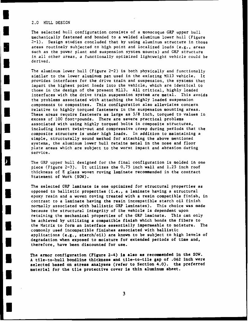
The selected hull configuration consists of a monocoque GRP upper hullmechanically fastened and bonded to a welded aluminum lower hull (Figure2-1). Design studies concluded that by using aluminum structure in thoseareas routinely subjected to high point and localized loads (e.g., areassuch as the power plant and suspension system mounts) and GRP structurein all other areas, a functionally optimized lightweight vehicle could be
* derived.
The aluminum lower hull (Figure 2-2) is both physically and functionallysimilar to the lower aluminum pan used in the existing M113 vehicle. Itprovides interfaces for the drive train and suspension, the systems thatimpart the highest point loads into the vehicle, which are identical tothose in the design of the present M113. All critical, highly loadedinterfaces with the drive train suspension system are metal. This avoidsthe problems associated with attaching the highly loaded suspensioncomponents to composites. This configuration also alleviates concernrelative to highly torqued fasteners in the suspension mounting areas.These areas require fasteners as large as 5/8 inch, torqued to values inexcess of 100 foot-pounds. There are severe practical problemsassociated with using highly torqued bolts in composite structures,including insert twist-out and compressive creep during periods that thecomposite structure is under high loads. In addition to maintaining asimple, structurally sound method for attaching the above mentionedsystems, the aluminum lower hull retains metal in the nose and floorplate areas which are subject to the worst impact and abrasion duringservice.
The GRP upper hull designed for the final configuration is molded in onepiece (Figure 2-3). It utilizes the 0.75 inch wall and 1.25 inch roofthickness of E glass woven roving laminate recommended in the contractStatement of Work (SOW).
The selected GRP laminate is one optimized for structural properties asopposed to ballistic properties (i.e., a laminate having a structuralepoxy resin and a woven roving treated with a resin compatible finish, incontrast to a laminate having the resin incompatible starch oil finishnormally associated with ballistic GRP laminates). This choice was madebecause the structural integrity of the vehicle is dependent uponretaining the mechanical properties of the GRP laminate. This can onlybe achieved by utilizing a compatible finish which bonds the fibers tothe Matrix to form an interface essentially impermeable to moisture. Thecommonly used incompatible finishes associated with ballisticapplications (e.g., starch/oil) are known to be subject to high levels ofdegradation when exposed to moisture for extended periods of time and,therefore, have been discounted for use.
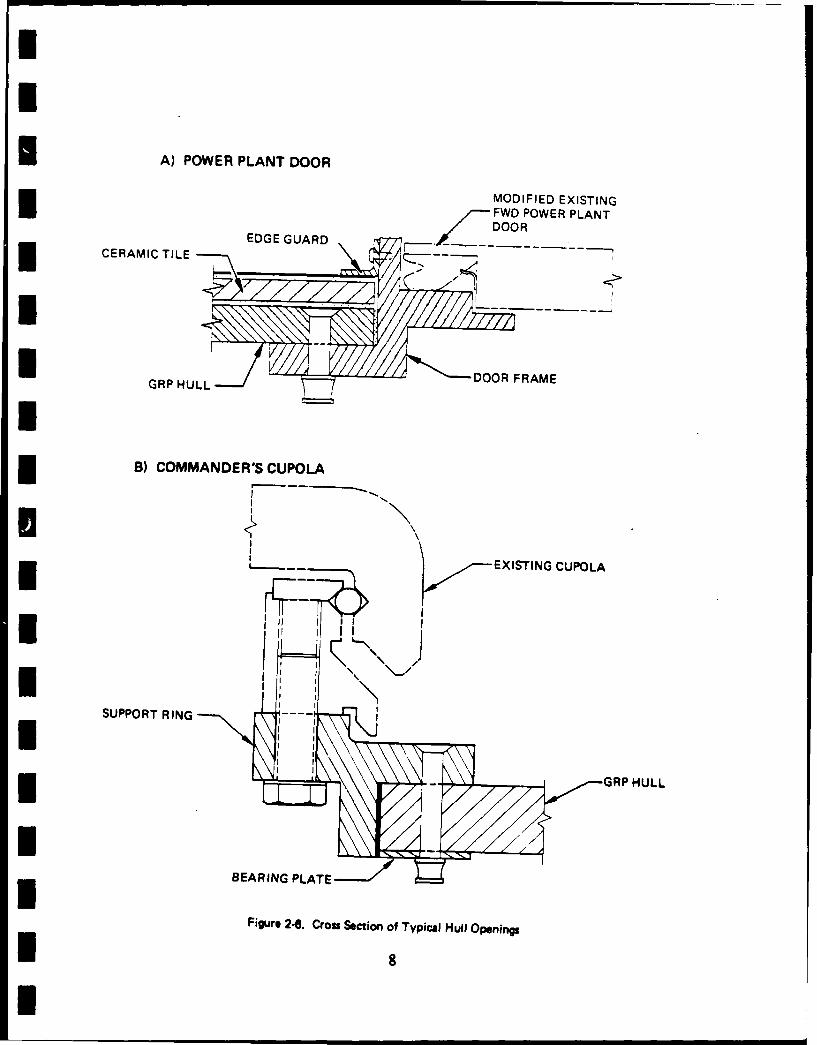
The armor configuration (Figure 2-4) is also as recommended in the SOW.A tile-to-hull bondline thickness and tile-to-tile gap of .062 inch wereselected based on stress analyses (refer to Section 4.0). the preferredmaterial for the tile protective cover is thin aluminum sheet.
3
I
IGRP UPPER HULLI
I _
ALUMINUM LOWER HULL
Figure 2.1. Hull Assembly
I,IIII
I Figure 2.2. Aluminum Lower Hull4I
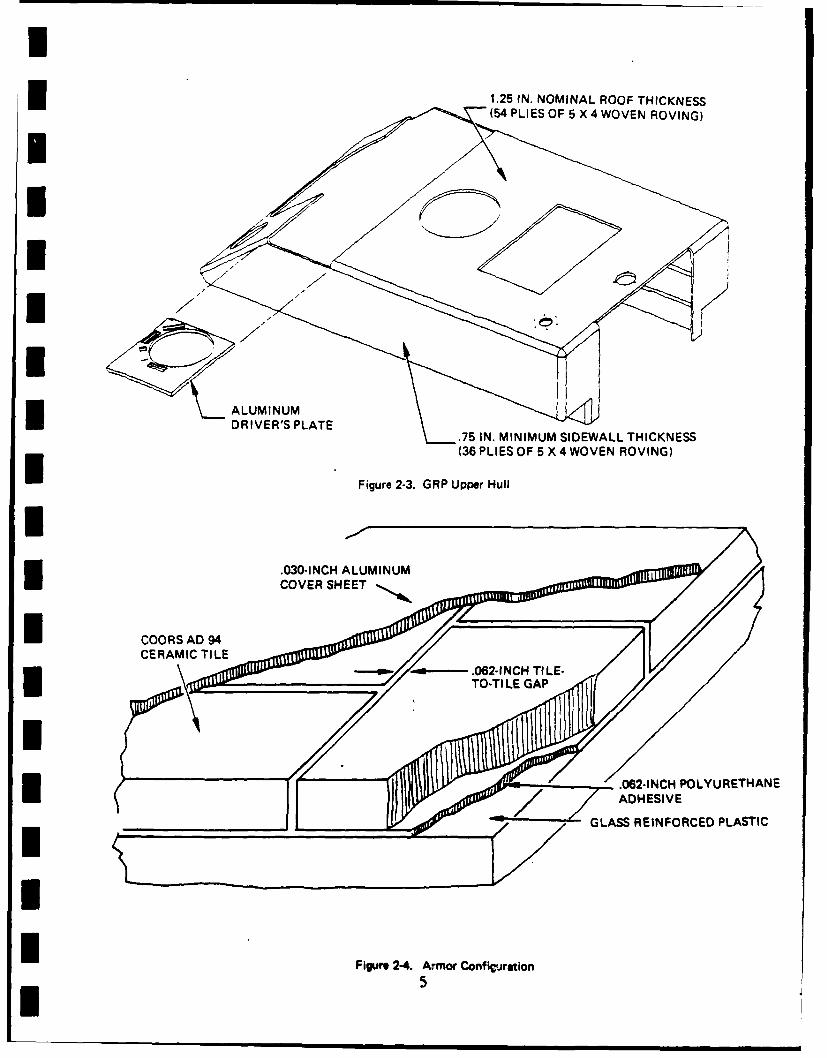
1.25 IN. NOMINAL ROOF THICKNESS(54 PLIES OF 5 X 4 WOVEN ROVING)
II
l ALUMINUM
R P.75 IN. MINIMUM SIDEWALL THICKNESS(36 PLIES OF 5 X 4 WOVEN ROVING)
Figure 2-3. GRP Upper Hull
.030-INCH ALUMINUMCOVER SHEET
i COORS AD 94
CE RM ICTIL '-, -------. 062-1NCH TI LE-TOoTI LE GAP
~Figure 2-4. Armor Configuration
15
I
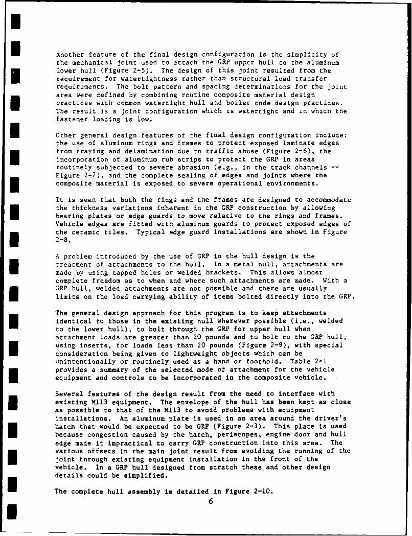
I Another feature of the final design configuration is the simplicity ofthe mechanical joint used to attach tho GRP upper hull to the aluminumlower hull (Figure 2-5). The design of this joint resulted from therequirement for watertightness rather than structural load transferrequirements. The bolt pattern and spacing determinations for the jointarea were defined by combining routine composite material designpractices with common watertight hull and boiler code design practices.The result is a joint configuration which is watertight and in which thefastener loading is low.
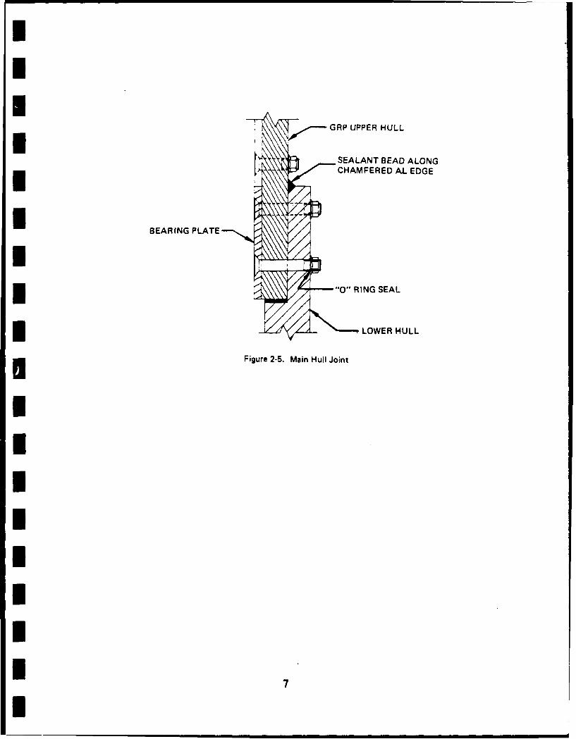
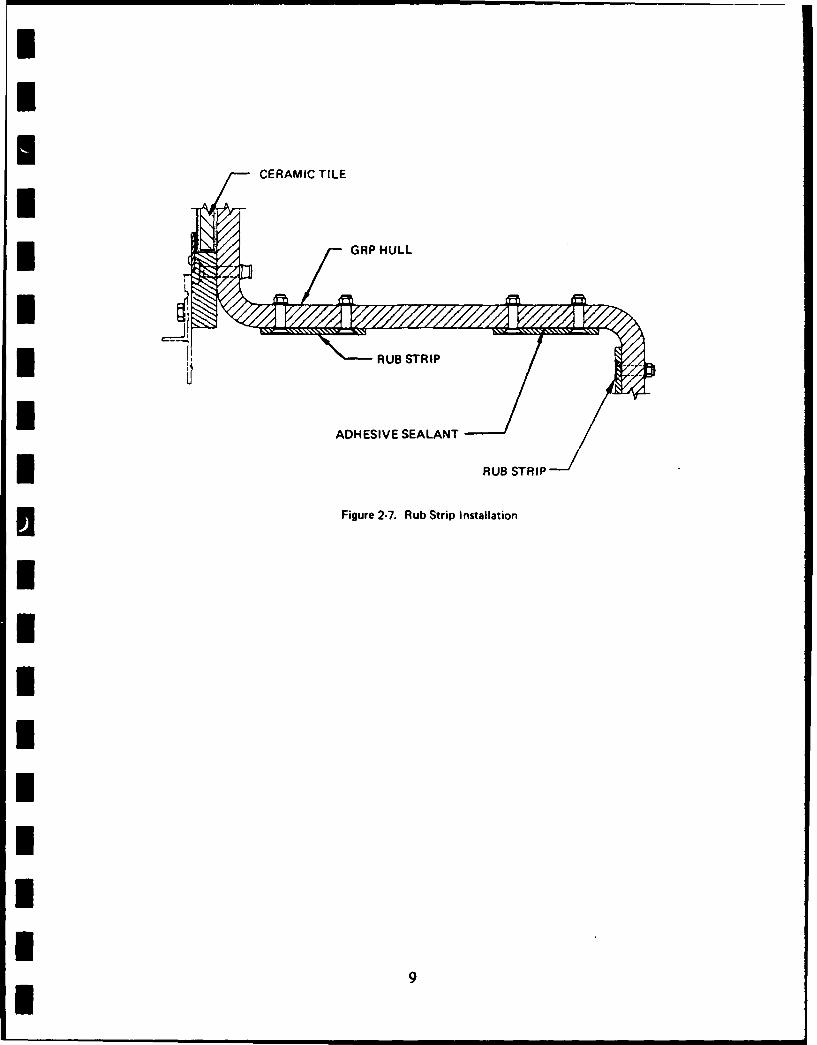
n Other general design features of the final design configuration include:the use of aluminum rings and frames to protect exposed laminate edgesfrom fraying and delamination due to traffic abuse (Figure 2-6), theincorporation of aluminum rub strips to protect the GRP in areasroutinely subjected to severe abrasion (e.g., in the track channels --Figure 2-7), and the complete sealing of edges and joints where the
n composite material is exposed to severe operational environments.
It is seen that both the rings and the frames are designed to accommodatethe thickness variations inherent in the GRP construction by allowingbearing plates or edge guards to move relative to the rings and frames.Vehicle edges are fitted with aluminum guards to protect exposed edges ofthe ceramic tiles. Typical edge guard installations are shown in Figure2-8.
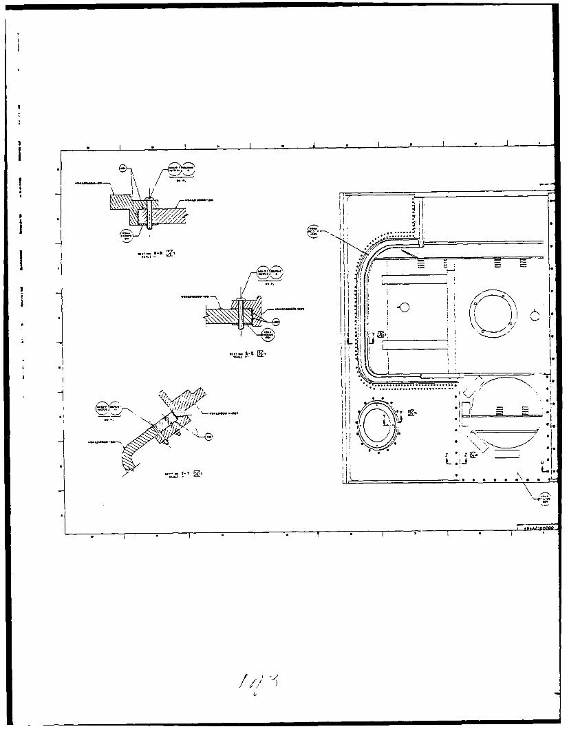
A problem introduced by the use of GRP in the hull design is thetreatment of attachments to the hull. In a metal hull, attachments aremade by using tapped holes or welded brackets. This allows almostcomplete freedom as to when and where such attachments are made. With aGRP hull, welded attachments are not possible and there are usuallylimits on the load carrying ability of items bolted directly into the GRP.
The general design approach for this program is to keep attachmentsidentical to those in the existing hull wherever possible (i.e., weldedto the lower hull), to bolt through the GRP for upper hull whenattachment loads are greater than 20 pounds and to bolt to the GRP hull,using inserts, for loads less than 20 pounds (Figure 2-9), with special
consideration being given to lightweight objects which can beunintentionally or routinely used as a hand or foothold. Table 2-1provides a summary of the selected mode of attachment for the vehicleequipment and controls to be incorporated in the composite vehicle.
Several features of the design result from the need to interface withexisting M113 equipment. The envelope of the hull has been kept as closeas possible to that of the M113 to avoid problems with equipmentinstallations. An aluminum plate is used in an area around the driver'shatch that would be expected to be GRP (Figure 2-3). This plate is usedbecause congestion caused by the hatch, periscopes, engine door and hulledge made it impractical to carry GRP construction into this area. Thevarious offsets in the main joint result from avoiding the running of the
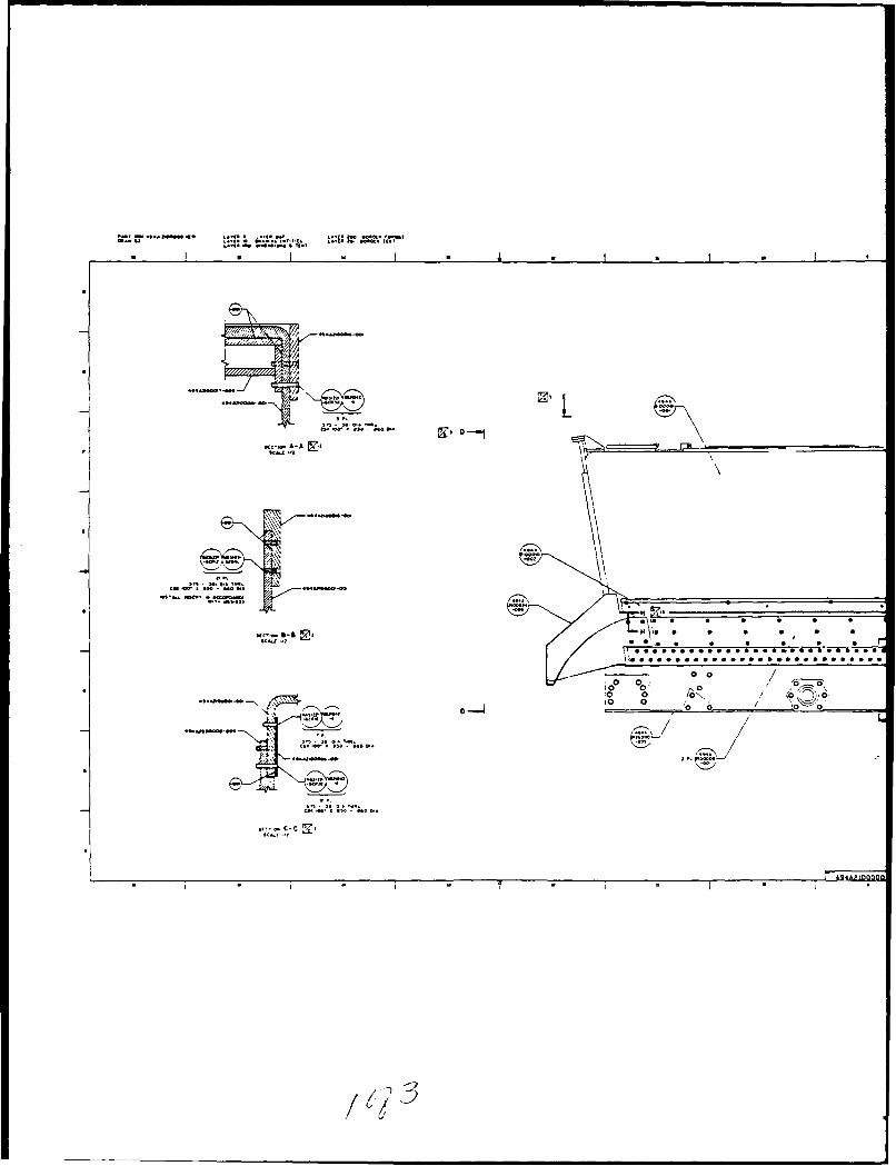
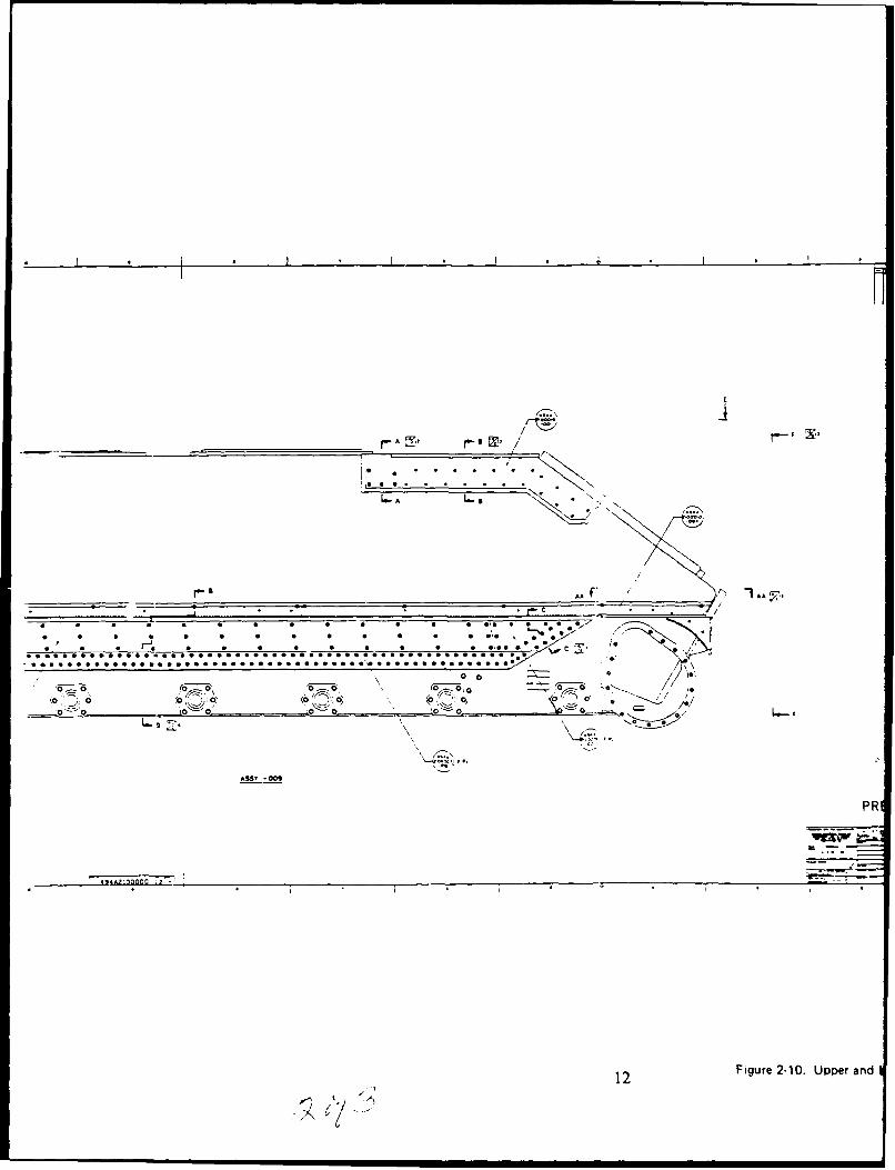
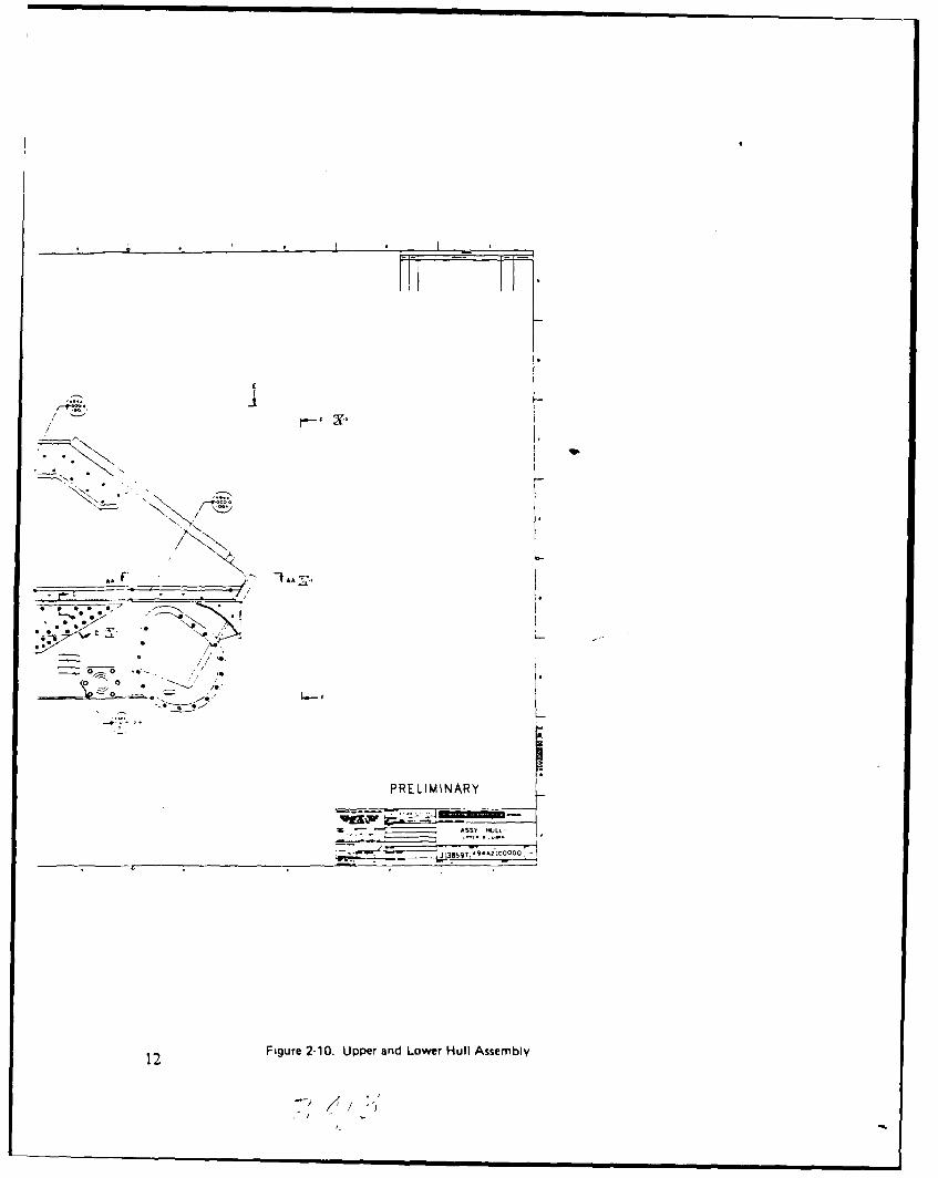
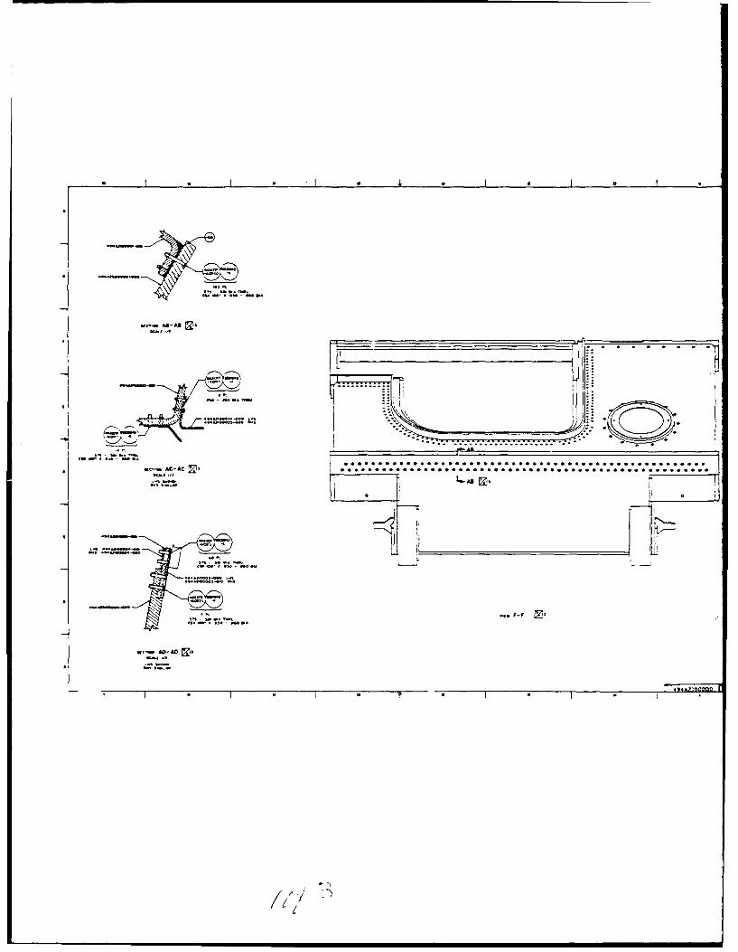
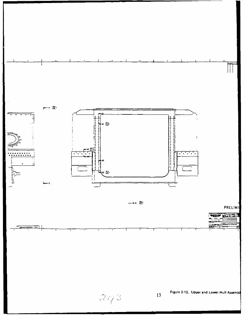
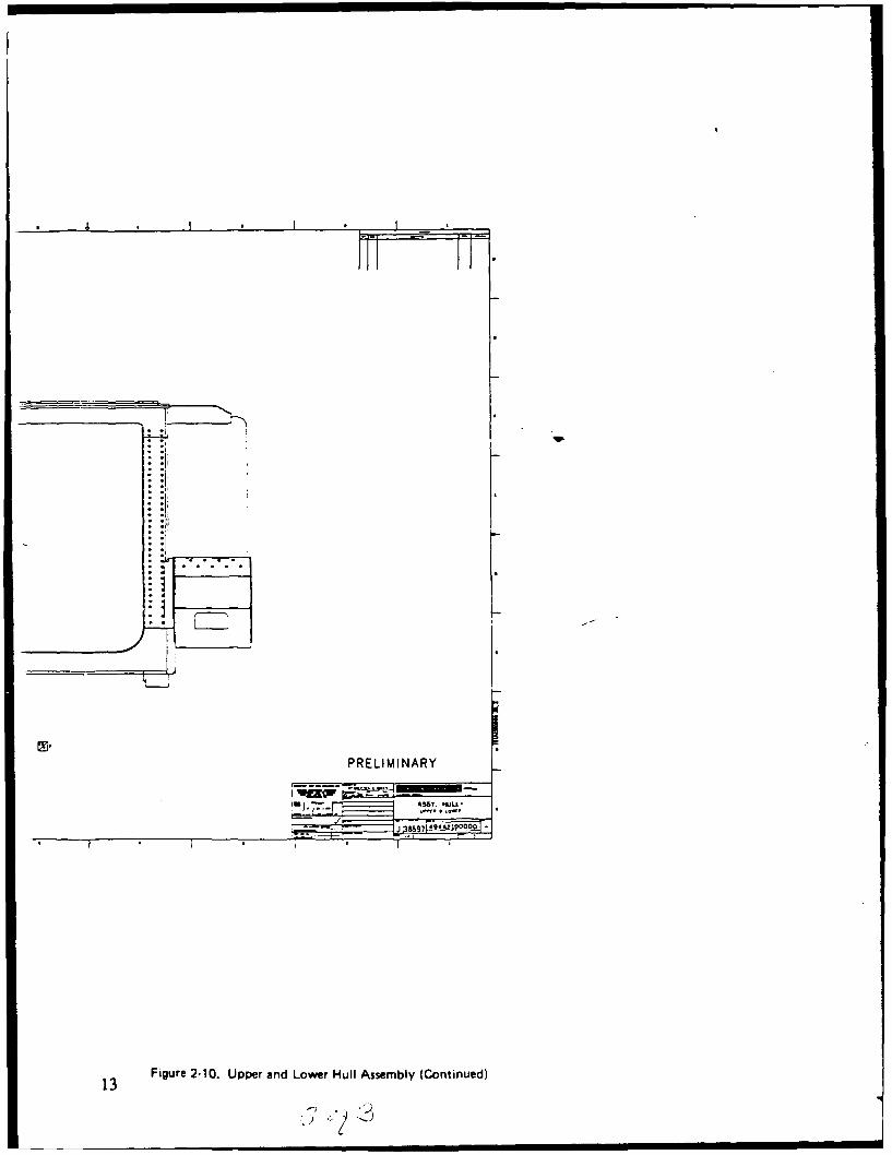
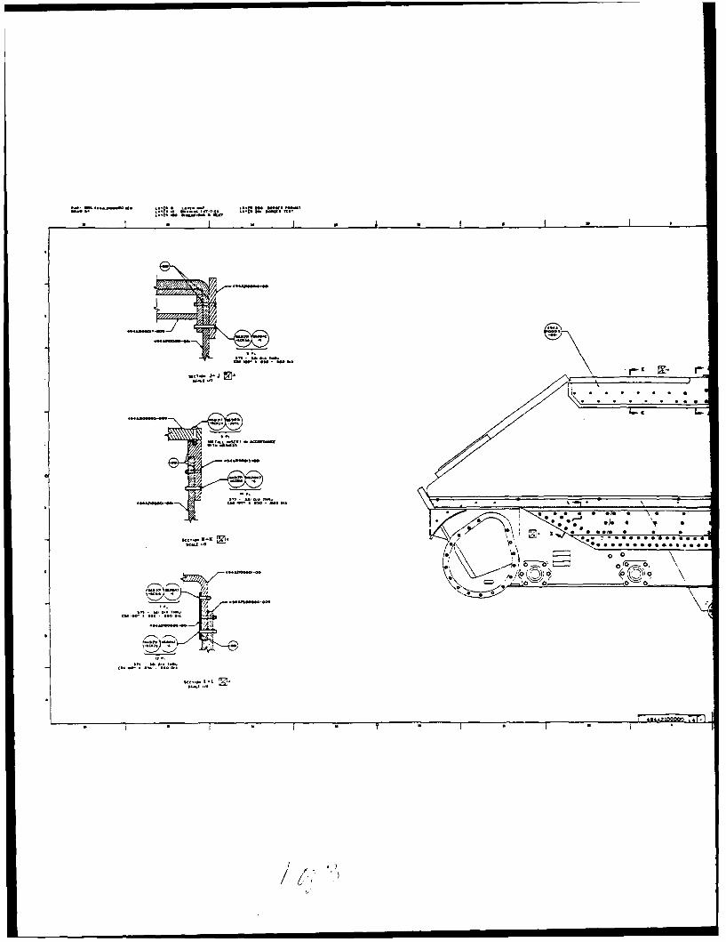
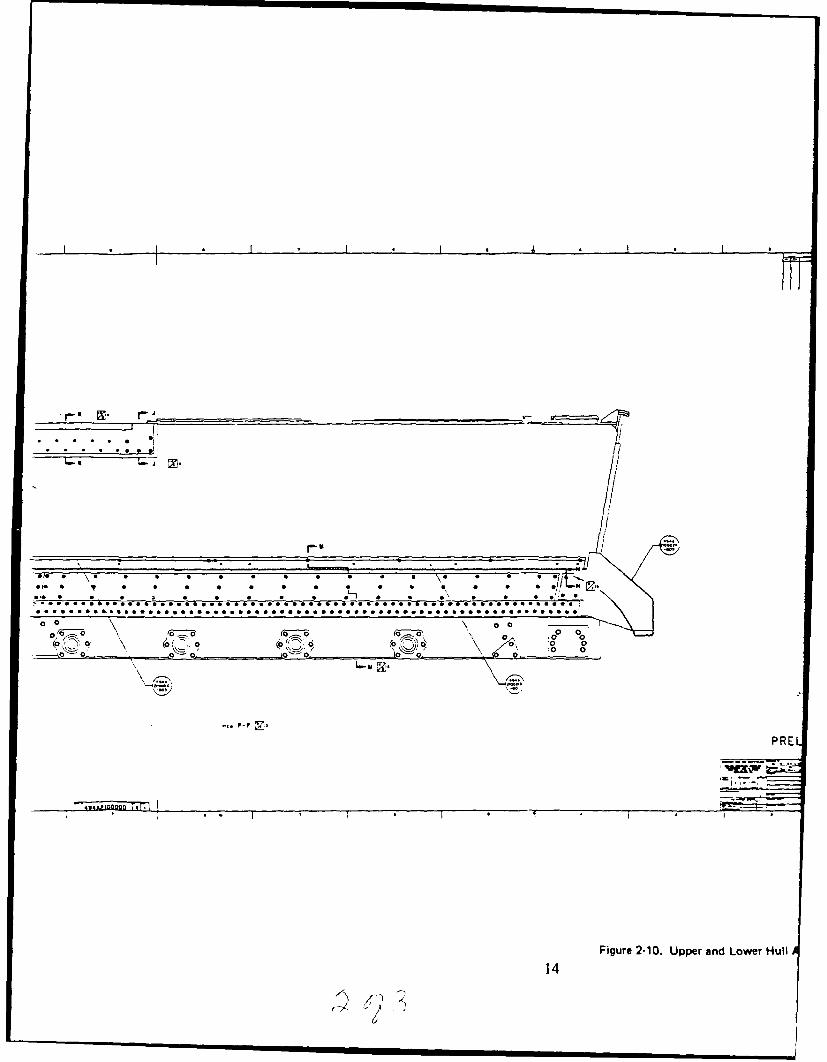
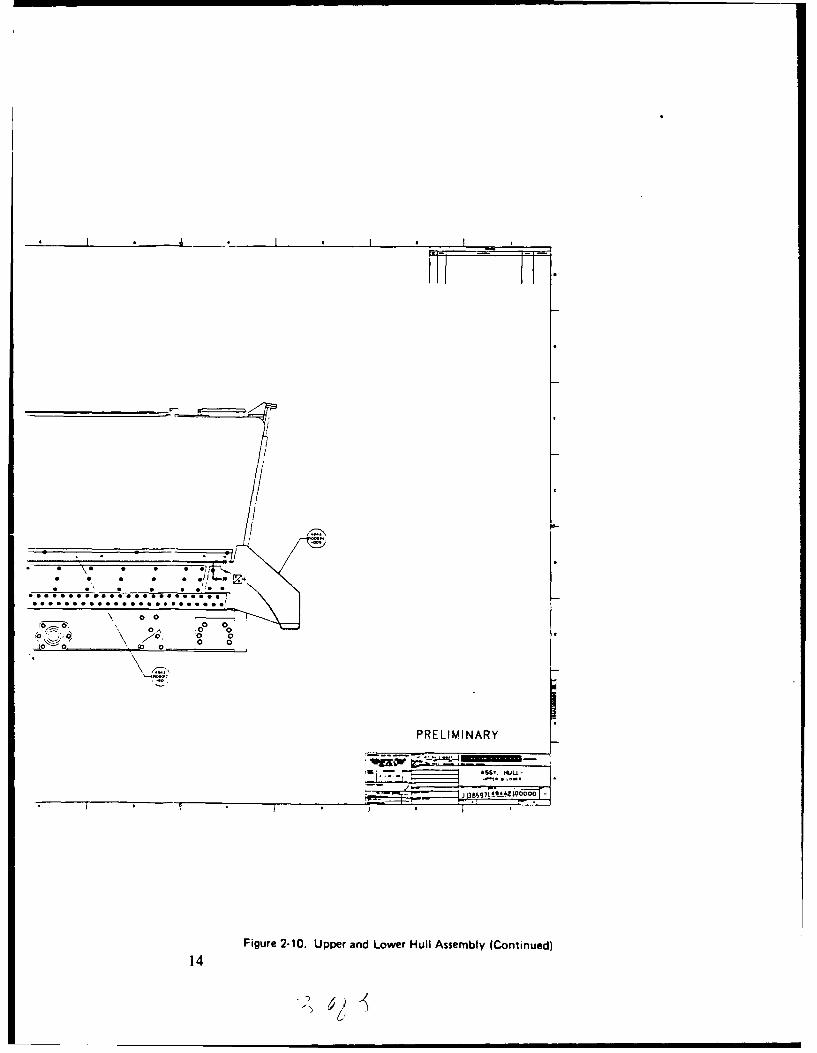
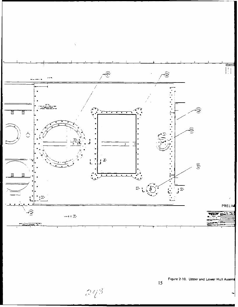
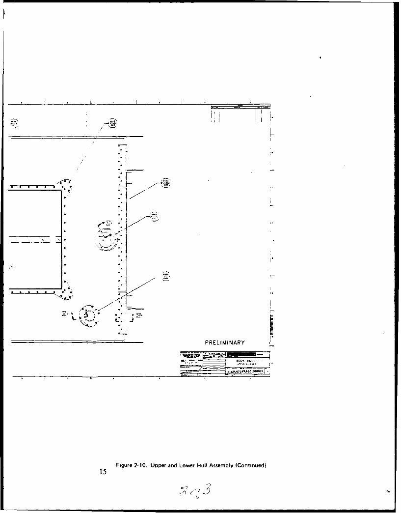
joint through existing equipment installation in the front of thevehicle. In a GRP hull designed from scratch these and other designdetails could be simplified.The complete hull assembly is detailed in Figure 2-10.
6
II
GRP UPPER HULL
I SEALANT BEAD ALONGCHAMFERED AL EDGE
I BEARING PLATE
-"O" RING SEAL
*/- LOWER HULL
* Figure 2-5. Main Hull Joint
IIIIIIII7I
I A) POWER PLANT DOOR
MODIFIED EXISTINGFWD POWER PLANTDOOR
EDGE GUARD ~ - - -~I CERAMIC TILE
*RHL.9 DOOR FRAME
B) COMMANDER'S CUPOLA
EXISTING CUPOLA
SUPPORT RING
BEARING PLATE
Figure 2-4. Cross Section of Typical Mull Openings
I 8
III
CERAMIC TILEI
I ADHESIVE SEALANT
RUB STRIP
Figure 2-7. Rub Strip Installation
IIIIIII
I
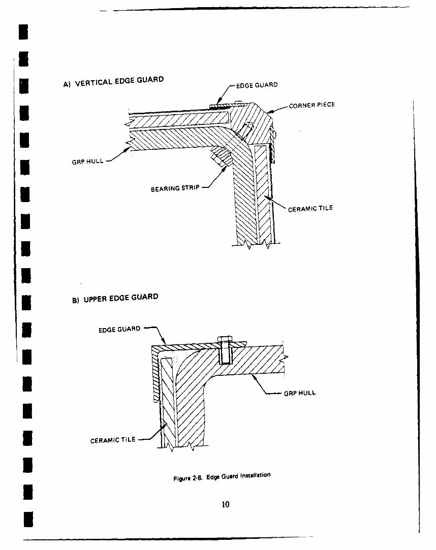
A) VERTICAL EDGE GUARD EG UR
I CORNER PIECE
I GRP HULL
BERNUTII CERAMIC TILE
B) UPPER EDGE GUARD
I EDGE GUARD
I CERAMIC TILE
Figure 2-8. Edge Guard Installation
10
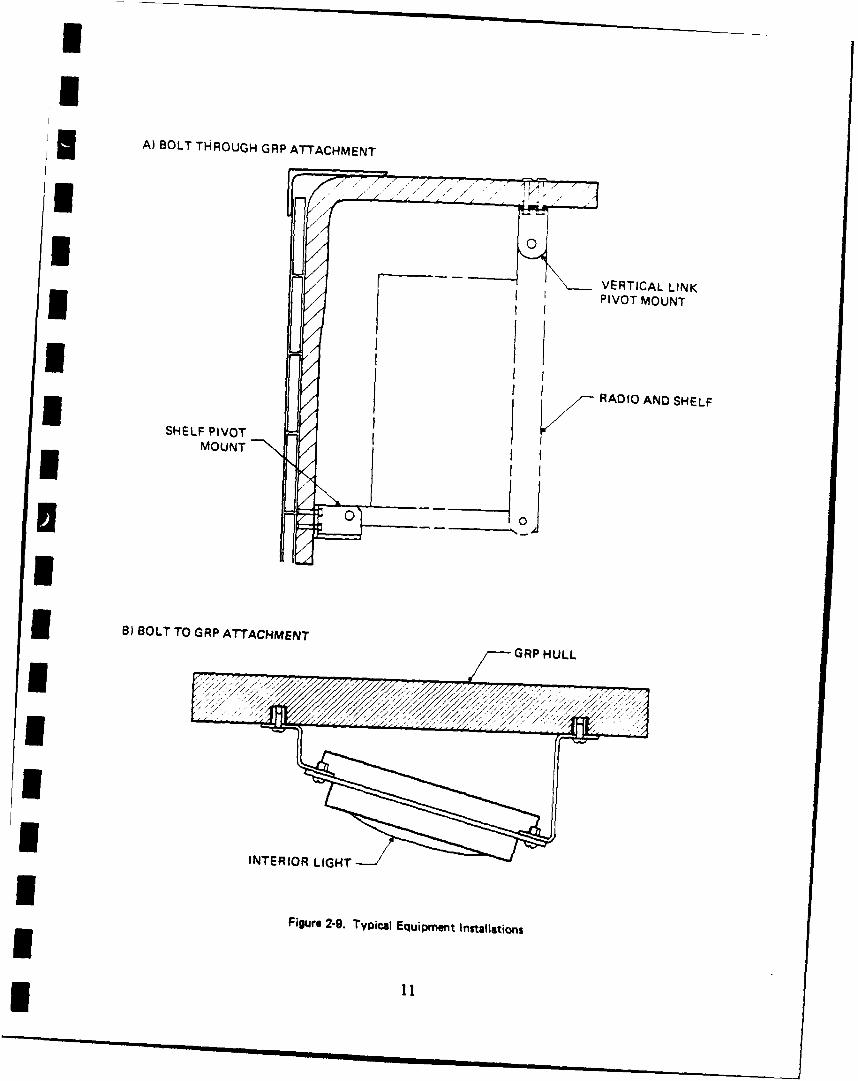
j A) BOLT THROUGH GRP ATTACHMENT
I K 0VERTICAL LINKPIVOT MOUNT
SHEL PIV T IRADIO AND SHELF
MOUNT
3 1) BOLT TO GRP ATTACHMENT GPHL
INTERIOR LIGHT
Figure 2-9. Typical Equipment Installations
p~~~~0 0'- L(*00*9
0flh.0oCO.0 001 '
t0~ c' 8 SO -00*5 ~ , ~.e.
C 0
J2AID0
A > AA'
W..~S. 0 0 0. .0. . . .
0 0
(0, 10o 01 -. ~' '
0o 00 0
ASS' -00M
PR
12 Figure 2-10. Upper andI
///
EI
" . '7 AA
PRELIMINARY
- ASSY MULL
12 Figure 2-10. Upper and Lower Hull Assembly
? 7• /
nc.. AD-AN
.. .... .. ... ...
.... ...-.c , .o- -. - ..... *.*-....- "...'
ne.nAt-AC Ell 0 .* . 0 0
* I
'-'-- -.
S' ADAD
4 * 4 * S S i
• | I I -
NINAt~
1* L
-. 0-cPRELIMI
Figure 2-10. Upper and Lower Hull Assemb13
.4l
PRELIMINARY
UAS!Y. ONU.J
13 Figure 2-10. Upper and Lower Hull Assembly (Continued)
13'7<
* 0 A 0 0 0
-I-K ~ I-
0
K*A0Aflfl~flA T~E, CO
/
I *.*.* 0 0 00 0 0 00 ~ . .. ;~J .1. *
0< W 1 0 OOTO 0 0 0TCTT* K 0
0
SCALA '4 0* 0~*0*0 *0
~
7
'-(0 ~0~* TO-'
'A' - I ~-
* I * I * * I * I F 4,rn~nao r0 F- I
(7 ')
0 -- a aC %
:0 0
PRE
-7-
Figure 2-10. Upper and Lower Hull
14
* I • *
iT-nt.
0 0
. 0" 0. ".." . " •0
0o,0o o 0 ,
PRELIMINARY
-- ~ AS*.t. o-a
I*I * .J ,7! '~O O
Figure 2-10. Upper and Lower Hull Assembly (Continued)
14
2) i ) 1
II
... - ............ ..
_ I
* ** I*
/ .
* /
/ _ _
0 0/ ./
. / ° :~.. //
[p o-\ I 0
_ _ _ , . ,o ., 0•
'.. '. N.C
-.. .. - . . _0.0. " 0:..
___"__- '-___V
Fur.!..Uperadoer.ulAse
(1 6' ' • • o
WH
1-
* * * S S S S
C C.
S rS
S S
5<'
PRELIMINARY L_
Figure 2-10. Upper and Lower Hull Assembly (Continued)15
~ . )
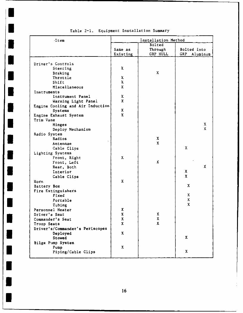
I Table 2-1. Equipment Installation Summary
-Item Installation Method
BoltedSame as Through Bolted Into
__Driver's Controls Existing GRP HULL GRP Aluminum
Steering XBraking XThrottle XShift XMiscellaneous X
InstrumentsInstrument Panel XWarning Light Panel X
Engine Cooling and Air InductionSystems X
Engine Exhaust System XTrim Vane
Hinges XDeploy Mechanism X
Radio SystemRadios X
Antennae XCable Clips X
Lighting SystemsFront, Right XFront, Left XRear, Both X
Interior XCable Clips X
Horn XBattery Box X
Fire ExtinguishersFixed XPortable X
Tubing XPersonnel Heater XDriver's Seat X K
Commander's Seat X X
Troop Seats X X
Driver's/Commander's PeriscopesDeployed XStowed X
Bilge Pump SystemPump XPiping/Cable Clips X
II
16U
I
3.0 REPAIRABILITY STUDY
The possible introduction of GRP hulls into the armored vehicle fleetraises significant questions about repairability. GRP hulls will requiredifferent repair equipment and technology than steel or aluminum hulls.From a practical standpoint it is virtually impossible to predict allpossible damage cases that could occur on a hull; therefore, only repairof the damage cases contained in the contract SOW were analyzed.
The following combination of ballistic and non-ballistic damage cases andmaintenance levels in the SOW were considered:
Damage Cases:
I 1) Roof - single, completely penetrating ballistic impact by a fragmentsimulating projectile which leaves a six-inch diameter damagedarea. The hole in the damaged area is assumed to be two inches indiameter.
2) Sides - single ballistic impact by an armor piercing roundcompletely penetrating and shattering a single ceramic tile but notthe reinforcing GRP.
3) Sides - single ballistic impact completely penetrating andshattering the ceramic tile and the GRP causing a three-inchdiameter damaged area. The hole in the damaged area is assumed tobe one inch in diameter.
4) Sides - a ceramic tile completely pulled off the hull.
* 5) Overall - repairability of hull after collisions:
a) The loss of a final drive unit which is torn from the hull* during an impact.
b) The loss of a front or rear fender due to impact.
c) A hole in the vehicle hull caused by a collision with a tree,rock or other vehicle. The size of the damage area is assumedto be one foot in diameter with a through hull penetration areaof six inches in diameter.
Level of Repair:
Level I - Repair of damage from Damage Cases I) or 3) above by thevehicle crew so that the watertight integrity of the hull isrestored.
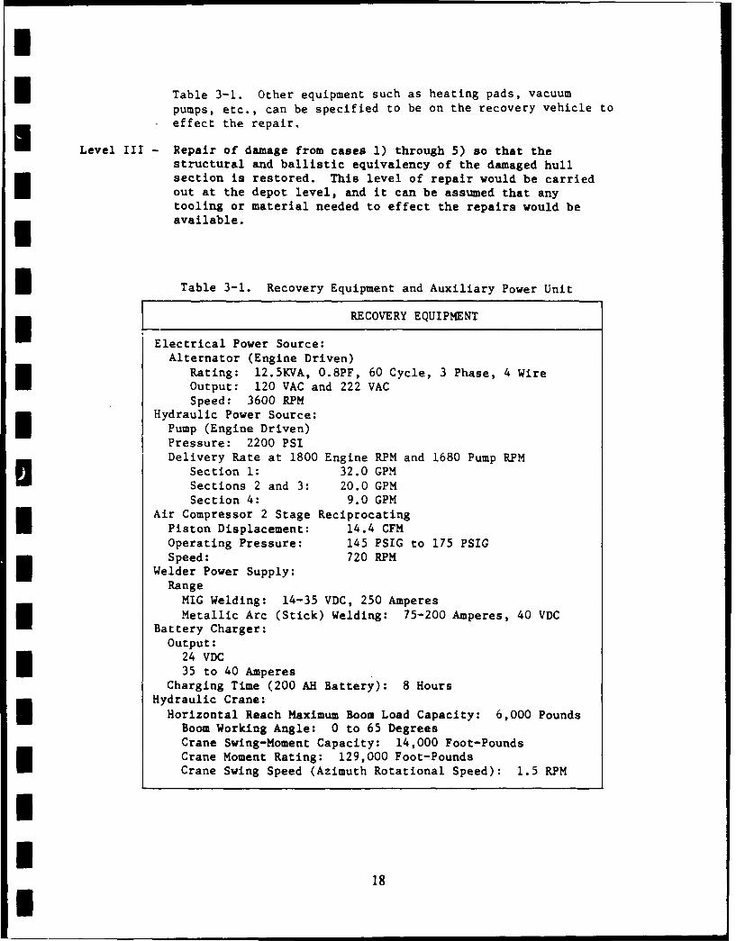
Level II - Repair of damage from Damage Cases 1), 2), 3), or 4) above bya field/organizational maintenance unit so that the ballisticprotection equivalency and watertight integrity of the damagedhull section is restored. For the purposes of this study, theservices of a recovery vehicle can be assumed to be availableto the damaged vehicle. Recovery vehicle equipment is listed in
17I
I
I Table 3-1. Other equipment such as heating pads, vacuumpumps, etc., can be specified to be on the recovery vehicle toeffect the repair.
Level III - Repair of damage from cases 1) through 5) so that thestructural and ballistic equivalency of the damaged hullsection is restored. This level of repair would be carriedout at the depot level, and it can be assumed that anytooling or material needed to effect the repairs would beavailable.
fl Table 3-1. Recovery Equipment and Auxiliary Power Unit
Electrical Power Source:
RECOVERY EQUIPMENT
Alternator (Engine Driven)Rating: 12.5KVA, O.8PF, 60 Cycle, 3 Phase, 4 WireOutput: 120 VAC and 222 VACSpeed: 3600 RPM
Hydraulic Power Source:Pump (Engine Driven)Pressure: 2200 PSI
Delivery Rate at 1800 Engine RPM and 1680 Pump RPMSection 1: 32.0 GPMSections 2 and 3: 20.0 GPMSection 4: 9.0 GPM
Air Compressor 2 Stage ReciprocatingPiston Displacement: 14.4 CFMOperating Pressure: 145 PSIG to 175 PSIGSpeed: 720 RPM
Welder Power Supply:RangeMIG Welding: 14-35 VDC, 250 AmperesMetallic Arc (Stick) Welding: 75-200 Amperes, 40 VDC
Battery Charger:Output:
24 VDC35 to 40 Amperes
Charging Time (200 AH Battery): 8 HoursHydraulic Crane:
Horizontal Reach Maximum Boom Load Capacity: 6,000 PoundsBoom Working Angle: 0 to 65 DegreesCrane Swing-Moment Capacity: 14,000 Foot-PoundsCrane Moment Rating: 129,000 Foot-Pounds
Crane Swing Speed (Azimuth Rotational Speed): 1.5 RPM
II
18
I
II
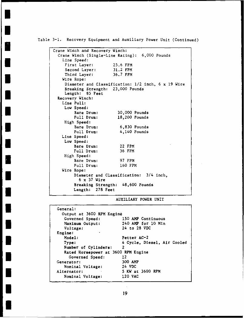
Table 3-1. Recovery Equipment and Auxiliary Power Unit (Continued)
U Crane Winch and Recovery Winch:Crane Winch (Single-Line Rating): 6,000 Pounds
Line Speed:First Layer: 25.6 FPMSecond Layer: 31.2 FPMThird Layer: 36.7 FPM
Wire Rope:Diameter and Classification: 1/2 inch, 6 x 19 WireBreaking Strength: 23,000 PoundsLength: 85 Feet
Recovery Winch:Line Pull:Low Speed:
Bare Drum: 30,000 PoundsFull Drum: 18,200 Pounds
High Speed:Bare Drum: 6,830 PoundsFull Drum: 4,140 Pounds
Line Speed:Low Speed:
Bare Drum: 22 FPMFull Drum: 36 FPM
High Speed:Bare Drum: 97 FPMFull Drum: 160 FPM
Wire Rope:Diameter and Classification: 3/4 inch,6 x 37 Wire
Breaking Strength: 48,600 PoundsLength: 278 Feet
AUXILIARY POWER UNIT
* General:Output at 3600 RPM EngineGoverned Speed: 150 AMP ContinuousMaximum Output: 240 AMP for 10 MinVoltage: 24 to 28 VDC
Engine:Model: Petter AC-2Type: 4 Cycle, Diesel, Air CooledNumber of Cylinders: 2Rated Horsepower at 3600 RPM EngineGoverned Speed: 12
Generator: 300 AMPNominal Voltage: 24 VDC
Alternator: 5 KW at 3600 RPM
Nominal Voltage: 120 VAC
I19
I
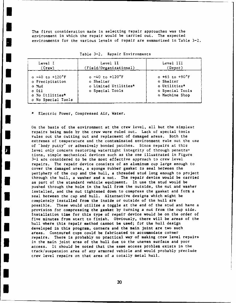
The first consideration made in selecting repair approaches was theenvironment in which the repair would be carried out. The expected
environments for the various levels of repair are summarized in Table 3-2.
Table 3-2. Repair Environments
Level I Level II Level III(Crew) (Field/Organizational) (Depot)
I o -40 to +120*F o -40 to +120*F o +65 to +90°Fo Precipitation o Shelter o Sheltero Mud o Limited Utilities* o Utilities*o Oil o Special Tools o Special Toolso No Utilities* o Machine Shop
m o No Special Tools
* Electric Power, Compressed Air, Water.IOn the basis of the environment at the crew level, all but the simplestrepairs being made by the crew were ruled out. Lack of special toolsrules out the cutting out and replacment of damaged areas. Both theextremes of temperature and the contaminated environment rule out the use
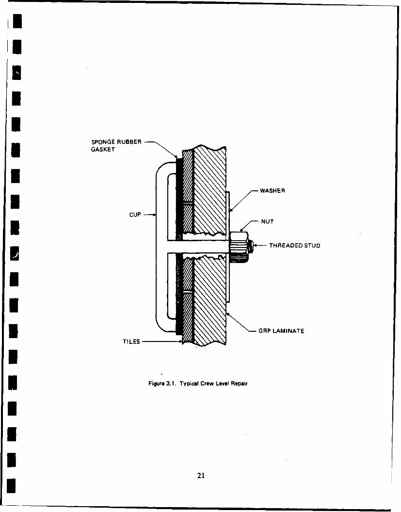
of "body putty" or adhesively bonded patches. Since repairs at thislevel only concern restoring watertight integrity of through penetra-tions, simple mechanical devices such as the one illustrated in Figure3-1 are considered to be the most effective approach to crew levelrepairs. The repair device consists of an aluminum cup large enough tocover the damaged area, a sponge rubber gasket to seal between theperiphery of the cup and the hull, a threaded stud long enough to projectthrough the hull, a washer and a nut. The repair device would be carried
as part of the standard vehicle equipment. In use the stud would bepushed through the hole in the hull from the outside, the nut and washerinstalled, and the nut tightened down to compress the gasket and form aseal between the cup and hull. Alternative designs which might becompletely installed from the inside or outside of the hull arepossible. These would utilize a toggle at the end of the stud and have aprovision for compressing the gasket by turning a nut from the cup side.Installation time for this type of repair device would be on the order offive minutes from start to finish. Obviously, there will be areas of thehull where this repair method cannot be used; for the hull designdeveloped in this program, corners and the main joint are two suchareas. Contoured cups could be fabricated to accommodate cornerrepairs. There is probably no practical way of making crew level repairsin the main joint area of the hull due to the uneven surface and pooraccess. It should be noted that the same access problem exists in thetrack/suspension area of any armored vehicle and would probably precludecrew level repairs on that area of a totally metal hull.
20
IU
SPONGE RUBBERGASKETU
WASHER
CUP* NUT
THREADED STUD
I
IGRP LAMINATE
TILES
I
Figure 3.1. Typical Crew Level Repair
III
21I
The Level II and III repairs differ from one another only in theIcomplexity of the repairs that can be accomplished. At the field/organizational level it is assumed that local heating and shelter will beavailable. This plus common hand tools, equipment to flush away dirt andoil from the damaged area, and prefabricated patches will allow the useof bolted and bonded repairs to restore structural integrity in areas ofpenetrating and non-penetrating ballistic damage of the type described infl cases 1) through 4).
Repairs to items in damage case 5) will require more extensive facilitiesthan those required for the other damage cases because the extent of thedamaged area may not be obvious and the extent of the damaged area can behighly variable. The fact that the extent of the damage may not bereadily apparent requires that nondestructive inspection (NDI) equipmentbe available to map the extent of damage. As a minimum, ultrasonic andx-ray equipment will be required. Because the extent of damage can vary,the standard patches used at the field/organizational level will not beuseable in all cases; therefore, specially prepared patches will requiremachine shop facilities capable of machining thick GRP material.
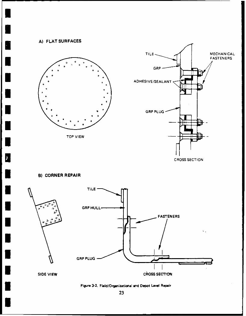
The repair procedure recommended for Level II and III repairs is a boltedand bonded patch similar to those illustrated in Figure 3-2. Bonded-onlyrepairs are not recommended because of the uncertainty of being able toclean the damaged laminate well enough to reliably obtain high strengthbonds and the time required to process a bonded-only repair. A hullwhich has been damaged in service will have been exposed to an unknownvariety of materials which could impair the strength of a bonded repair.Removing these contaminants completely so that a reliable bond can beobtained between a patch and a hull is very uncertain because cleaningprocesses must be tailored to specific contaminants. Because of theuncertainty involved in the cleaning process, a bonded and bolted repairprocedure is recommended. In this approach all loads are carried by thebolts and the adhesive acts as a sealant and a shim to fill gaps causedby tolerances on the patch and cut out area.
* The sequence of operations involved in each repair scheme is summarizedin Table 3-3. The cleaning of areas to be repaired would be accomplishedby flushing with water and solvent. Removal of damaged areas and
preparation of edges of the surrounding material can be accomplished withhand held power tools such as saws and routers. Patches would beinstalled with adhesive on the laying surfaces, fastener holes drilledand fasteners installed. The adhesive could then cure without further
attention. Local heat would be applied to the repair area to dry itafter cleaning and to aid in curing the adhesive at ambient temperaturesbelow about 60*F.
II
I 22I I
UI
A) FLAT SURFACES
TILE MECHANICALIIG -- MFASTENERSI0
ADH ESI VE/SEALANT
I GRP PLUG
I
II RP EW
SEECROSS SECTION
U B) CORNER REPAIR
* TILE
I
4 - ~G R P H U L L - - - 4
FASTENERS
I GRP PLUG
ISIDE VIEW CROSS SECTION
fl Figure 3-2. Field/Organizational and Depot Level Repair
23
U
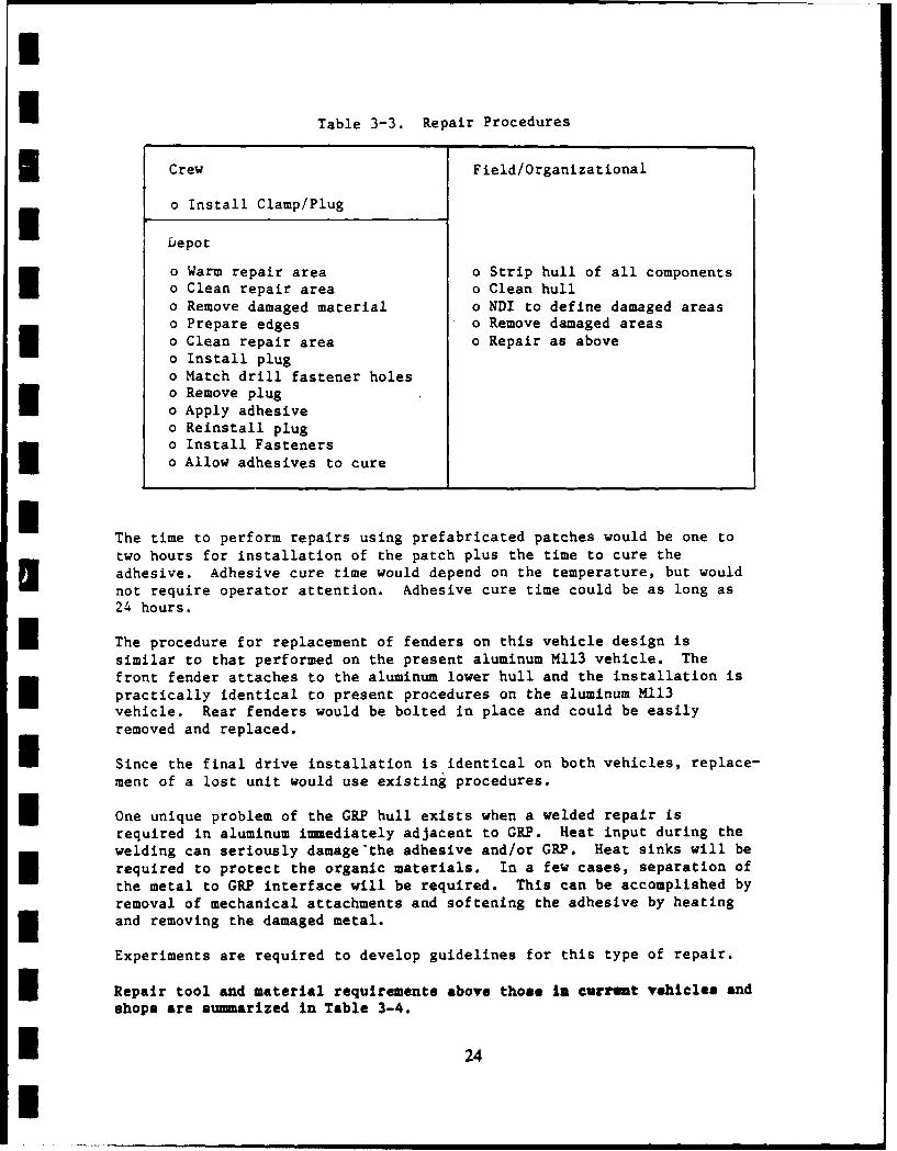
I Table 3-3. Repair Procedures
Crew Field/Organizational
o Install Clamp/Plug
Depot
o Warm repair area o Strip hull of all components
o Clean repair area o Clean hullo Remove damaged material o NDI to define damaged areaso Prepare edges o Remove damaged areaso Clean repair area o Repair as aboveo Install plugo Match drill fastener holeso Remove plug
o Apply adhesiveo Reinstall plugo Install Fastenerso Allow adhesives to cure
The time to perform repairs using prefabricated patches would be one totwo hours for installation of the patch plus the time to cure theadhesive. Adhesive cure time would depend on the temperature, but would
not require operator attention. Adhesive cure time could be as long as24 hours.
I The procedure for replacement of fenders on this vehicle design issimilar to that performed on the present aluminum M113 vehicle. Thefront fender attaches to the aluminum lower hull and the installation ispractically identical to present procedures on the aluminum M113vehicle. Rear fenders would be bolted in place and could be easilyremoved and replaced.
I Since the final drive installation is identical on both vehicles, replace-ment of a lost unit would use existing procedures.
I One unique problem of the GRP hull exists when a welded repair isrequired in aluminum immediately adjacent to GRP. Heat input during thewelding can seriously damage'the adhesive and/or GRP. Heat sinks will berequired to protect the organic materials. In a few cases, separation ofthe metal to GRP interface will be required. This can be accomplished byremoval of mechanical attachments and softening the adhesive by heating
*and removing the damaged metal.
Experiments are required to develop guidelines for this type of repair.
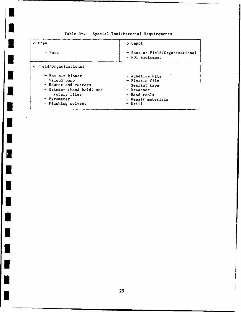
Repair tool and material requirements above those L current vehicles and
shops are summarized in Table 3-4.
I24
I
Table 3-4. Special Tool/Material Requirements
o Crew o Depot
- None - Same as Field/Organizational-NDI equipment
o Field/Organizational
S- Hot air blower - Adhesive kits- Vacuum pump - Plastic film- Router and cutters - Sealant tape- Grinder (hand held) and - Breather
rotary files - Hand tools- Pyrometer - Repair materials
S- Flushing solvent - Drill
I2IIIIIIIIU
25
I4.0 STRUCTURAL ANALYSIS
The GRP hull is shown in Figures 2-1 through 2-10. It is made up of a
GRP upper hull attached to an aluminum lower hull. The two are joined bya bolted, bonded joint at water line (WL) 25.5. For structural analysis,a minimum 0.75 inch wall thickness and a 1.25 inch roof thickness wereused. "B" Basis allowable stress and stiffness properties were used inthe analyses. The allowables were developed from 0 and 90' laminadata. The "SQ5' composite analysis computer code was used to generatelaminate properties. The allowable strength for the aluminum alloys used(5083, 5086, and 6061) were obtained from MIL-HDBK-5C. The strengths ofscrews and bolts were obtained from National Aerospace Standards (NAS)data sheets.
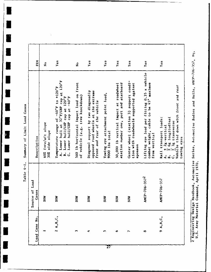
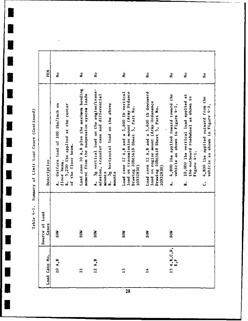
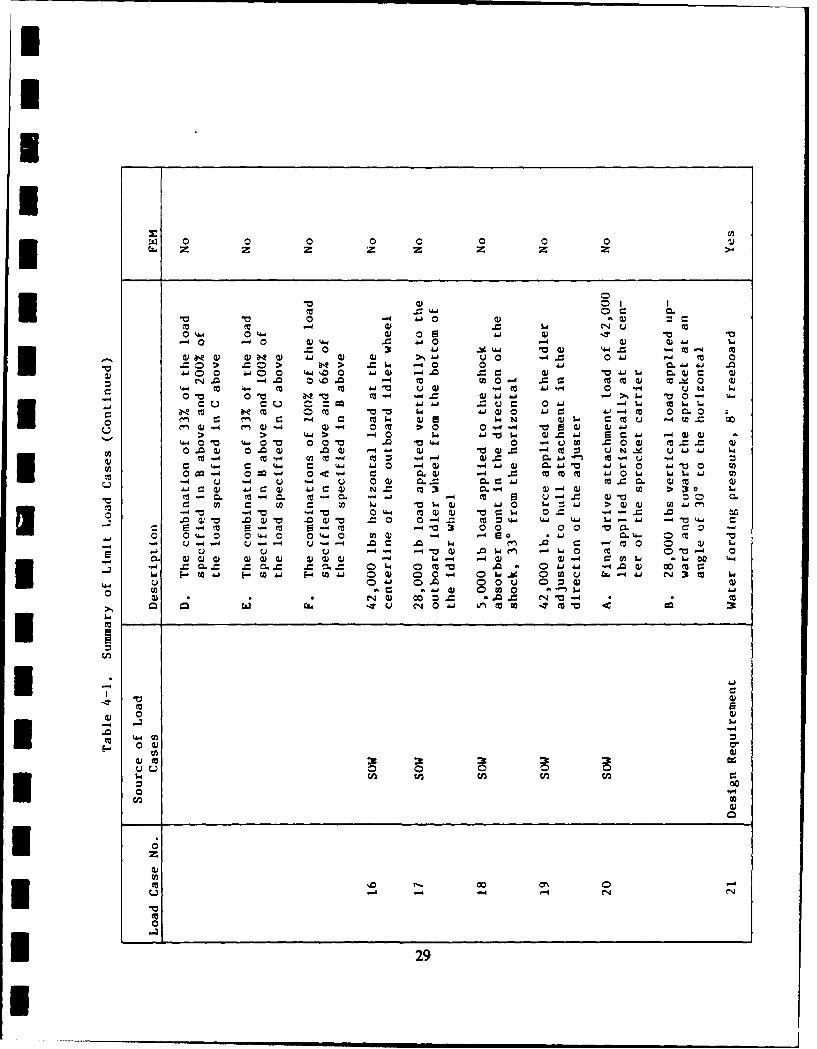
The results of the structural analysesI are summarized in the followingparagraphs. Structural analyses were performed for the loads outlined inTable 4-1. This table indicates the cases in which a finite elementanalysis was employed and those that were analyzed by hand. Table 4-1includes all operational loads defined in the SOW, plus a rail transportload condition based on an 8 mph railroad humping impact. The original12g longitudinal rail humping load was reduced to a 6g load becauseanalysis predicts the towing eyes used to tie the vehicle down duringtransport would fail at 6g. All'defined load conditions are consideredlimit loads. The hull has been designed so that no detrimental,permanent deformation occurs at design limit load conditions and nofailure occurs at design ultimate load conditions.
Consideration has been given to the effects of repeated loadingsresulting from transportation and operation. Since no M113 operationalload cycle data is available, a service life cannot be quantified.Standard fatigue resistant design techniques have been employed to
* minimize the impact of fatigue on the service life.
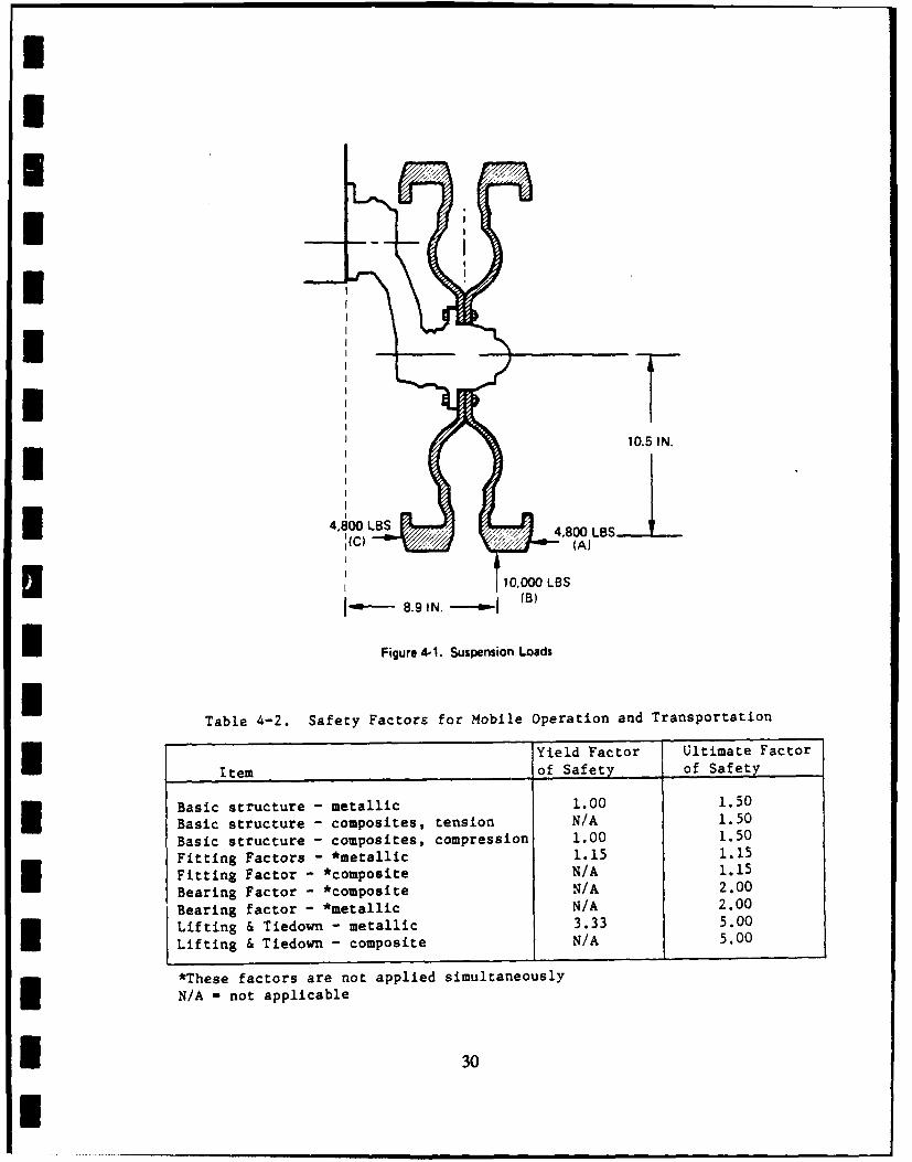
The factors of safety in Table 4-2 have been applied to the mobile5 operation and transportation loads.
III
I
1 M. Fisher, J. Wang, and A. Rosenwach, Composite Hull Tracked AmphibiousVehicle (M113), Structural Analysis Report, Martin Marietta Report No.BR 00230, August 1984. 26I2
Z U) C%4 0) w) U )
+ 0.
W La
0 W0
e cuma41 0 m2 c00u u0v-
-,-- - .'0 0 ) UAJ Ai0. L.. 0 0f.4 -- -4 ~ 0i La 4 -0 -j- wA
a Aj w) - -~4 =) m-- 4 0 > e 0. 00 U) w L
.6". .U) 0)U .61 0) cu ww 0000 4
LW 0)0 C aVt 0 0 - 4 > 41
CL0 >Z N' o.q C) J .6 c .0o 0LaCCO44 -U)~ 0)U.)U . M ~ 0 4w O)L 0) . .0O .0U0 LOU La 41) ) 0) CL V
en00 SO) Laf0 U~ (A4- cc A
4. 0)
OD 4
0~0 0cn*2
wz 0 0 00zz z z z z
-c Ws
C) C640 0~ CL I00 m -m 0010 >14 0 -
-V 00 C Is-4 6a -4 c 0 L0 W v
C0 0 c~ 0- 0.
m .61 0v 0
Li. pi c Cc~0 0 04 = -40 ws 0I. -w w 0 0.~ Q)w 0 col m 0 >V
a) OW 4.4 A4 -' -4 $ *o Lo r. .9c e o~ McC0- i.6J 04 to ') r-) W 0 1cP rn ccg ,
-~ 1. 0 -40 N ~ ~ ~ 0. ~ .a Ai * 0E w -4 m 0 - 0000'
0 LL 0 0 ) . o0 0 0 u ~ J -- - 0 0 WI. W > JaJ M W 0 - 00 0
u .6) 0 wc- 00 w~ Cc 0r0 Qc 0 4 0o w 0-I3 .4. swL el- nA -.4 CJ- Ct 0 rA c~ c tm "0aC 0 0 m tv 0000% 0'. . L6.. 0 0 * 0 . 0 01.4C0 0 010
t6 -4--4If z 14 .
0 4
~ 0-. 1-
.0
z.. f
(A j C ~ C~ ,UI 0N
U -~ 28
0 0 0 0 0
0) 0)H~ ~ CO00
0 ta -0)A
00 4.d. 'A. -a) 8e ) 0) K 0) 4j- A) 0 .0 m"
.C00 .Cd 0re wC
m 04' ~ 4 M 1-4 'J. N0 tU-.4 -. 4 -) C)C) 0 ) .6J OO 0 - 6
enC0 M w0) C0w N. c m..- 0J0 -4 W S4)0 -4 40 en 4) --4 0 m). >) 00 0. . 9A
uO > > 4. 0. WI.0 w 0 sw C0 0 41 r-A-r',0oW0" 0 -V0 0)1 0 ~ U. 04-. (vI0 4~ O.O 0 4) V~0 .- ) C~9 0u " N O 61 L
fa m -.W4 a)) C0 -. 4 0
0. -4 u -W 69 jm40) A. 4j0) r- Q)~* N 0 J -4 w > &
8Z -. 7 mN ' UrCO -. cO m 0 C
4.; 4 4
-. 7 m0),40
0) 0) 0 4oc C C14--
*m 0)om ITw3
10)
I 0
I 00
z
mO r. 0' -L4 .- 4 4C 1
I 29
I10.5III.
II
4,8 00 LB 4,8 00 LBS({C) (A)
U '7 '
I 10,00 LBS
" -"8.9,IN. (-,' B)
Figure 4-1. Suspension Load$
Table 4-2. Safety Factors for Mobile operation and Transportation
Yield Factor Ultimate Factor
Item of Safety of Safety
Basic structure - metallic 1.00 1.50
Basic structure - composites, tension N/A 1.50
Basic structure - composites, compression 1.00 1.50
Fitting Factors - *metallic 1.15 1.15FtigFactor - *composite N/A 1.15
Fitting,
Bearing Factor - *composite N/A 2.00
Bearing factor - *metallic N/A 2.00Lifting & Tiedown - metallic 3.33 5.00
Lifting & Tiedown - composite N/A 5.00
~*These factors are not applied simultaneously
N/A - not applicable
| 30
I'
I
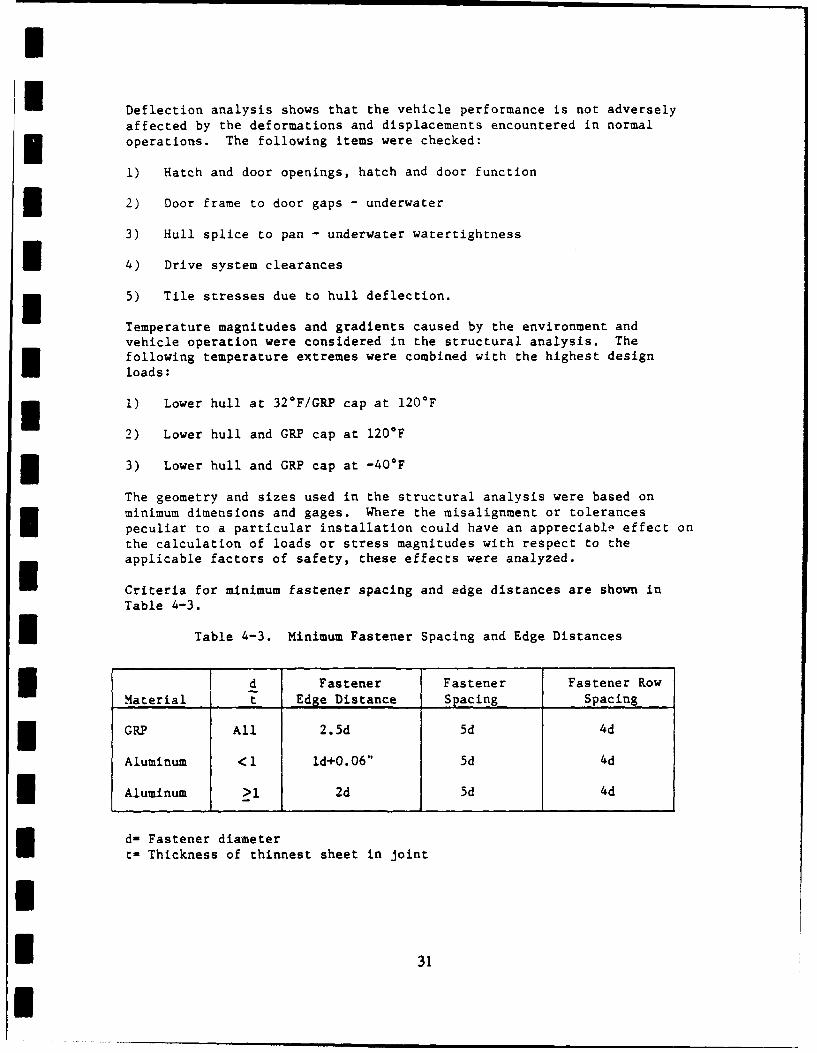
I Deflection analysis shows that the vehicle performance is not adversely
affected by the deformations and displacements encountered in normal
operations. The following items were checked:
1) Hatch and door openings, hatch and door function
2) Door frame to door gaps - underwater
3) Hull splice to pan - underwater watertightness
* 4) Drive system clearances
* 5) Tile stresses due to hull deflection.
Temperature magnitudes and gradients caused by the environment andvehicle operation were considered in the structural analysis. Thefollowing temperature extremes were combined with the highest design
loads:
1) Lower hull at 32*F/GRP cap at 120*F
2) Lower hull and GRP cap at 120*F
3) Lower hull and GRP cap at -40*F
The geometry and sizes used in the structural analysis were based onminimum dimensions and gages. Where the misalignment or tolerances
peculiar to a particular installation could have an appreciable effect on
the calculation of loads or stress magnitudes with respect to the
applicable factors of safety, these effects were analyzed.
Criteria for minimum fastener spacing and edge distances are shown in
Table 4-3.
i Table 4-3. Minimum Fastener Spacing and Edge Distances
d d Fastener Fastener Fastener Row
Material t Edge Distance Spacing Spacing
GRP All 2.5d 5d 4d
Aluminum <1 ld+O.06" 5d 4d
Aluminum >1 2d 5d 4d
d- Fastener diametert- Thickness of thinnest sheet in joint
I
I$3
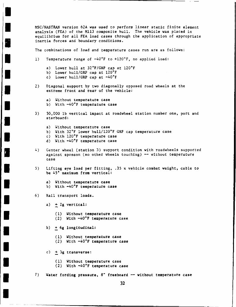
IMSC/NASTRAN version 62A was used to perform linear static finite elementanalysis (FEA) of the M113 composite hull. The vehicle was placed inequilibrium for all FEA load cases through the application of appropriateinertia forces and boundary conditions.
The combinations of load and temperature cases run are as follows:
1) Temperature range of -40°F to +1200 F, no applied load:
a) Lower hull at 32*F/GRP cap at 120*Fb) Lower hull/GRP cap at 120*Fc) Lower hull/GRP cap at -40°F
2) Diagonal support by two diagonally opposed road wheels at theextreme front and rear of the vehicle:
a) Without temperature caseb) With -40*F temperature case
3) 50,000 lb vertical impact at roadwheel station number one, port andm starboard:
a) Without temperature caseb) With 32*F lower hull/120°F GRP cap temperature casec) With 120*F temperature cased) With -400 F temperature case
4) Center wheel (station 3) support condition with roadwheels supported
against sponson (no other wheels touching) -- without temperaturecase
5) Lifting eye load per fitting, .35 x vehicle combat weight, cable tobe 450 maximum from vertical:
a) Without temperature caseb) With -40*F temperature case
m 6) Rail transport loads.
a) + 2g vertical:
(1) Without temperature case(2) With -40*F temperature case
b) + 6g longitudinal:
(1) Without temperature case(2) With -40*F temperature case
c) + 3g transverse:
(1) Without temperature case(2) With -40*F temperature case
7) Water fording pressure, 8" freeboard -- without temperature case
32
I
ds or thehul
rmie te iternal 'Oaheulod cases
rhe oad c s s w r used t dete i re c mbined 'with t
For a al to he sije the wOrs Qofr n RI 3 iso th oh the
tobl 4ete aoe ed ri ll~-- vith ai i t to -ut th e
The carjteds .ere ateral. meand
T h ed eT n d
branebet~ing ata ar CMi05 the
he m ties ofnin
rrie oa d Cto r the hee a nd
the ~ PC 14 tneI ?p Site
o 1303 wheel~ a rm
Iuse oft mate r e ,ie element s k s ,d f r t e fo
Iri o r 9 te f the pe late e i s v r were us 1I
,nding n S w e r e d
C thets ugh~ 4-5
It20 el me sg ar o n i 0 8
and s if f en ,n r
caftes.
enthe tie do and
elmns
BFb2DEG
43 Si eew 0i Finite ~ E laenm O
4-2. V 3
IIII
I
oH FRONT VIEW
I
I
I AFT VIEW
I Figure 4-4. Front and Aft View of Finite Element Model
I
I
I
I 0[ ~~111 l I I1 1I III A. __ _ E
Figure 4-5. Top View of Finite Element Model
I
The minimum margins of safety for each of the major components on thehull are shown in Table 4-4. A conservative approach was takenthroughout the analysis. For the GR upper hull, the highest singlepanel loads from the finite element runs were combined with the 140*F/wetGR design allowables to determine the minimum margin of safety. For the
aluminum lower hull, as-welded allowables were utilized whenever a highly
stressed area was located near a welded joint. For the load casesanalyzed by hand, the load cases supplied in the SOW were combined withthe worst case finite element model results to determine the minimummargin of safety. Margins of safety were positive for all cases analyzed.
IIIiI 35
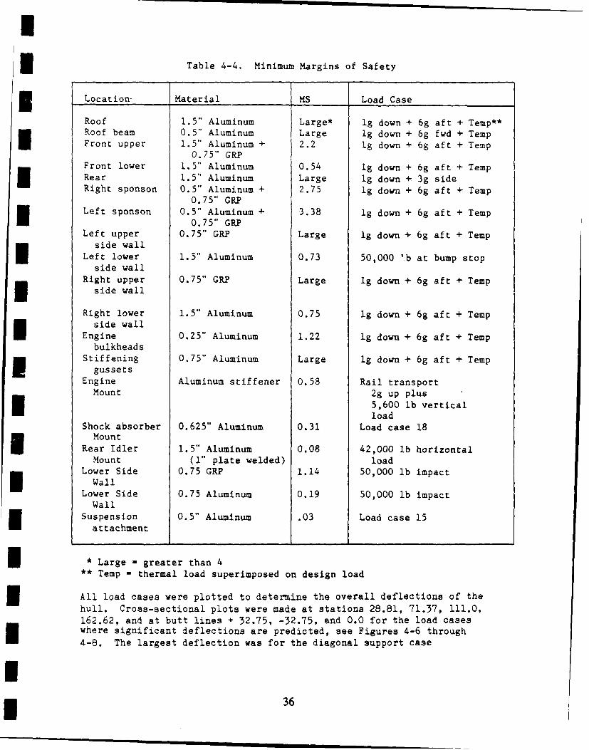
Table 4-4. Minimum Margins of Safety
3 Location- Material MS Load Case
Roof 1.5" Aluminum Large* ig down + 6g aft + Temp**Roof beam 0.5" Aluminum Large lg down + 6g fwd + TempFront upper 1.5" Aluminum + 2.2 Ig down + 6g aft + Temp0. 75" GRPFront lower 1.5" Aluminum 0.54 ig down + 6g aft + TempRear 1.5" Aluminum Large ig down + 3g sideRight sponson 0.5" Aluminum + 2.75 lg down + 6g aft + Temp
0.75" GRPLeft sponson 0.5" Aluminum + 3.38 lg down + 6g aft + Temp
0.75" GRPLeft upper 0.75" GRP Large Ig down + 6g aft + Temp
side wallLeft lower 1.5" Aluminum 0.73 50,000 ",b at bump stop
side wall
Right upper 0.75" GRP Large Ig down + 6g aft + Temp3I side wall
Right lower 1.5" Aluminum 0.75 lg down + 6g aft + Tempside wall
Engine 0.25" Aluminum 1.22 lg down + 6g aft + Tempbulkheads
Stiffening 0.75" Aluminum Large Ig down + 6g aft + Tempgussets
Engine Aluminum stiffener 0.58 Rail transportMount 2g up plus
5,600 lb verticalload
Shock absorber 0.625" Aluminum 0.31 Load case 18Mount
Rear Idler 1.5" Aluminum 0.08 42,000 lb horizontalMount (1" plate welded) load
Lower Side 0.75 GRP 1.14 50,000 lb impactWall
Lower Side 0.75 Aluminum 0.19 50,000 lb impactWall
Suspension 0.5" Aluminum .03 Load case 15attachment
* Large - greater than 4
** Temp - thermal load superimposed on design load
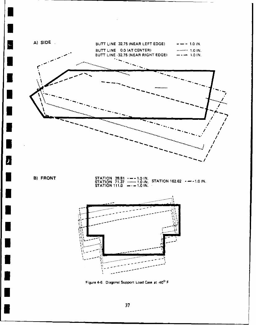
All load cases were plotted to determine the overall deflections of thehull. Cross-sectional plots were made at stations 28.81, 71.37, 111.0,162.62, and at butt lines + 32.75, -32.75, and 0.0 for the load caseswhere significant deflections are predicted, see Figures 4-6 through
4-8. The largest deflection was for the diagonal support case
36
A) SIDE BUTT LINE 32.75 (NEAR LEFT EDGE) -- 1.0 IN.
BUTT LINE 0.0 (AT CENTER) ..... 10IN.BUTT LINE -32.75 (NEAR RIGHT EDGE) -- 1.0 IN.
..... ... .. ...
5 -.. ........
.................... ******...*'7*i*. -
I .~~ ~~~ . ~ ..............5-*...*a 5................
B) FRONT STATION.2. .0 IN.
STATON.......N..TATION162.62.....IN
FiAgure1. 4-..iaonl1uportLadCsea.-0
I3
IA) SIDE BUTT LINE 32.75 - 0.1 IN.
BUTT LINE 0.0 ....... 0.1 IN.
BUTT LINE -32.75 -.- 0.1 IN.
I %.a- 4-
. . . . . . . . . . .. . . . . . . . . . . . . . . . . . . .
8) FRONT
STATION 28.81 0.1 IN.
STATION 71.37 0.1 IN.
STATION 111.0.......0.1 IN.
STATION 162.62 -- 0.1 IN.
------ -
--------
. ........
. ... ........ . ............
Figure 4-7. Load Case, 50,000 Lbs Applied at Bump Stop at .400 F
* 38
A) SIDE IUT(E3.5 "-.)N
BuTT LINE 0.0 ....... 1.0 IN.
BUTT LINE -32.75 - , -1-0 IN.
B) FRONT
STATION 28.81 0.1 IN.
STATION 71.37 ..... 1' IN.
I STATIONtt. 11.0 0.1 IN.
STATION 162.62 - 1 IN.
I I------- --
Figure~~~ 4-.La aelgDw 9Aa -4O
'39
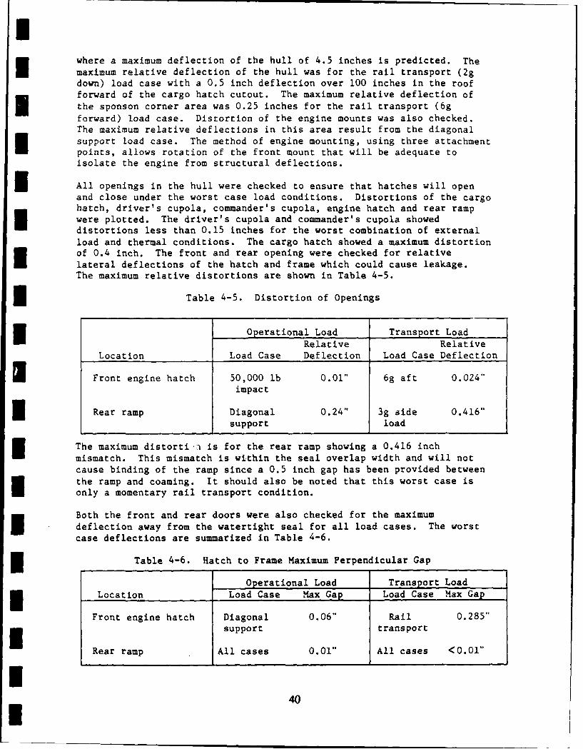
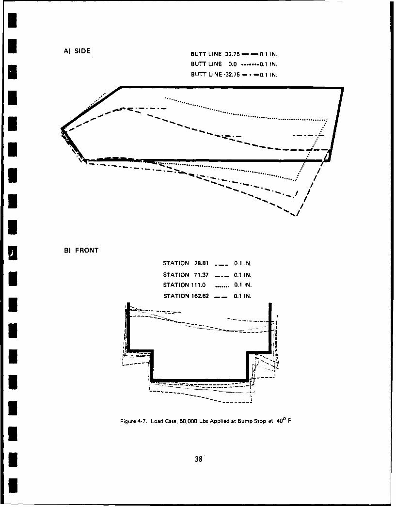
where a maximum deflection of the hull of 4.5 inches is predicted. Themaximum relative deflection of the hull was for the rail transport (2gdown) load case with a 0.5 inch deflection over 100 inches in the roofforward of the cargo hatch cutout. The maximum relative deflection ofthe sponson corner area was 0.25 inches for the rail transport (6gforward) load case. Distortion of the engine mounts was also checked.The maximum relative deflections in this area result from the diagonalsupport load case. The method of engine mounting, using three attachmentpoints, allows rotation of the front mount that will be adequate toisolate the engine from structural deflections.
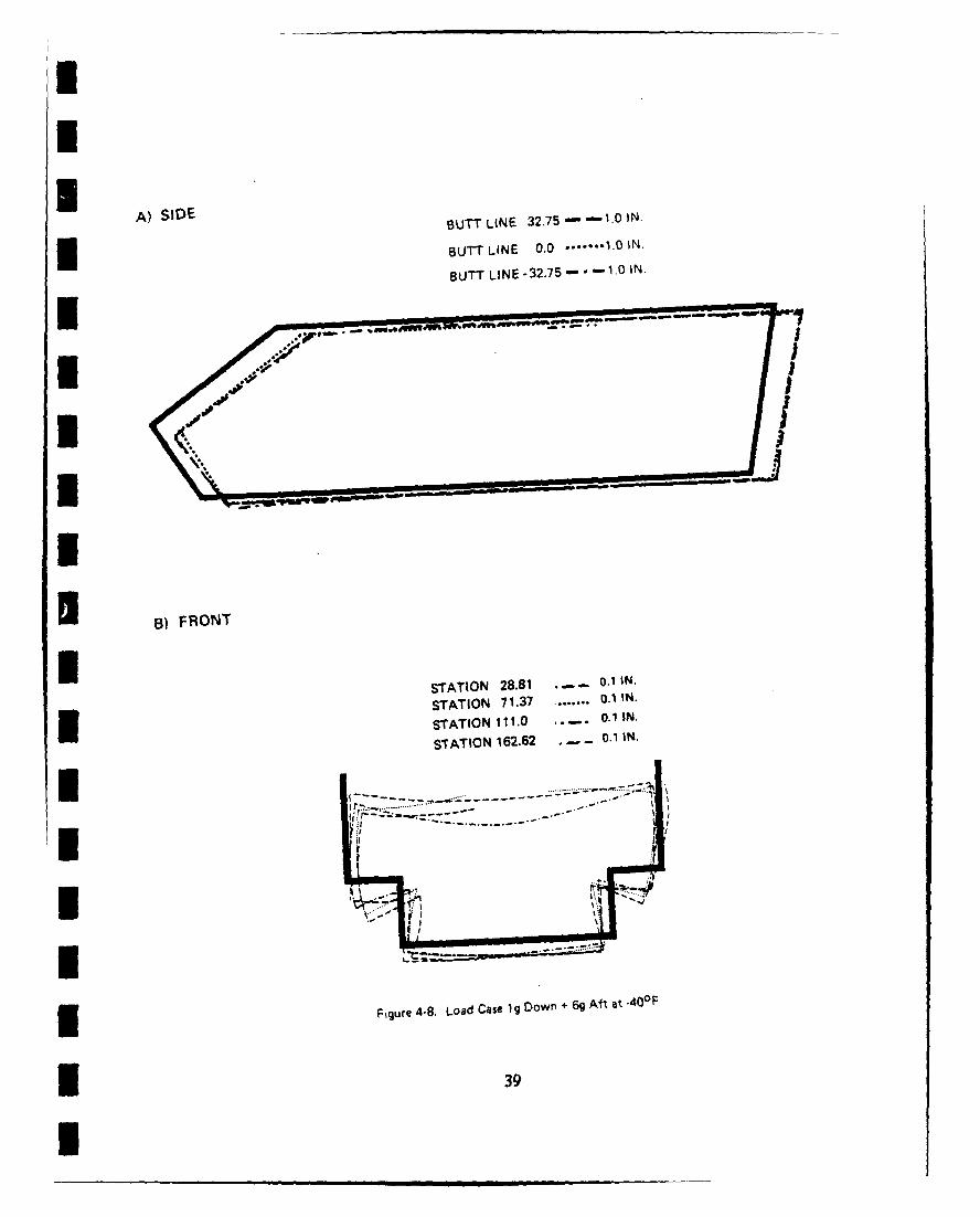
3 All openings in the hull were checked to ensure that hatches will openand close under the worst case load conditions. Distortions of the cargohatch, driver's cupola, commander's cupola, engine hatch and rear rampwere plotted. The driver's cupola and commander's cupola showeddistortions less than 0.15 inches for the worst combination of externalload and thermal conditions. The cargo hatch showed a maximum distortionof 0.4 inch. The front and rear opening were checked for relativelateral deflections of the hatch and frame which could cause leakage.The maximum relative distortions are shown in Table 4-5.
3 Table 4-5. Distortion of Openings
Operational Load Transport LoadRelative Relative
Location Load Case Deflection Load Case Deflection
1 Front engine hatch 50,000 lb 0.01" 6g aft 0.024"impact
Rear ramp Diagonal 0.24" 3g side 0.416"support load
The maximum distorti i is for the rear ramp showing a 0.416 inchmismatch. This mismatch is within the seal overlap width and will notcause binding of the ramp since a 0.5 inch gap has been provided betweenthe ramp and coaming. It should also be noted that this worst case isonly a momentary rail transport condition.
Both the front and rear doors were also checked for the maximumdeflection away from the watertight seal for all load cases. The worstcase deflections are summarized in Table 4-6.
Table 4-6. Hatch to Frame Maximum Perpendicular Gap
Operational Load Transport Load3 Location Load Case Max Gap Load Case Max Gap
Front engine hatch Diagonal 0.06" Rail 0.285"support transport
Rear ramp All cases 0.01" All cases <0.01"
440I
I All deflections for the operational load cases are within the 0.25 inchallowable deflection of the seals.
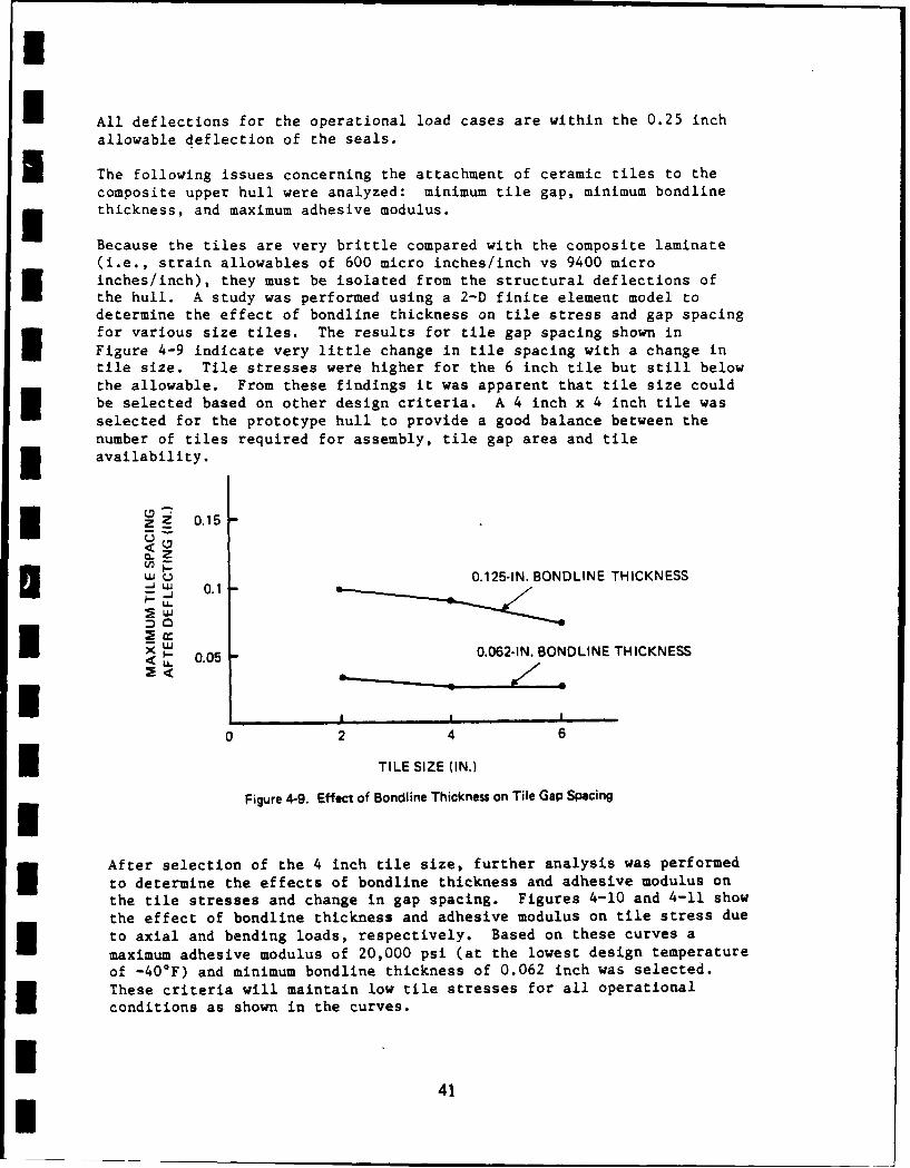
U The following issues concerning the attachment of ceramic tiles to thecomposite upper hull were analyzed: minimum tile gap, minimum bondlinethickness, and maximum adhesive modulus.
Because the tiles are very brittle compared with the composite laminate(i.e., strain allowables of 600 micro inches/inch vs 9400 microinches/inch), they must be isolated from the structural deflections ofthe hull. A study was performed using a 2-D finite element model todetermine the effect of bondline thickness on tile stress and gap spacingfor various size tiles. The results for tile gap spacing shown in
Figure 4-9 indicate very little change in tile spacing with a change intile size. Tile stresses were higher for the 6 inch tile but still belowthe allowable. From these findings it was apparent that tile size couldbe selected based on other design criteria. A 4 inch x 4 inch tile was
selected for the prototype hull to provide a good balance between thenumber of tiles required for assembly, tile gap area and tileE availability.
ZI 0.15CLZ
w U 0.125-IN. BONDLINE THICKNESSI- 0.1
* 0.05 0.062-IN. BONDLINE THICKNESS
II I I
0 2 4 6
TILE SIZE (IN.)
Figure 4-9. Effect of Bondline Thickness on Tile Gap Spacing
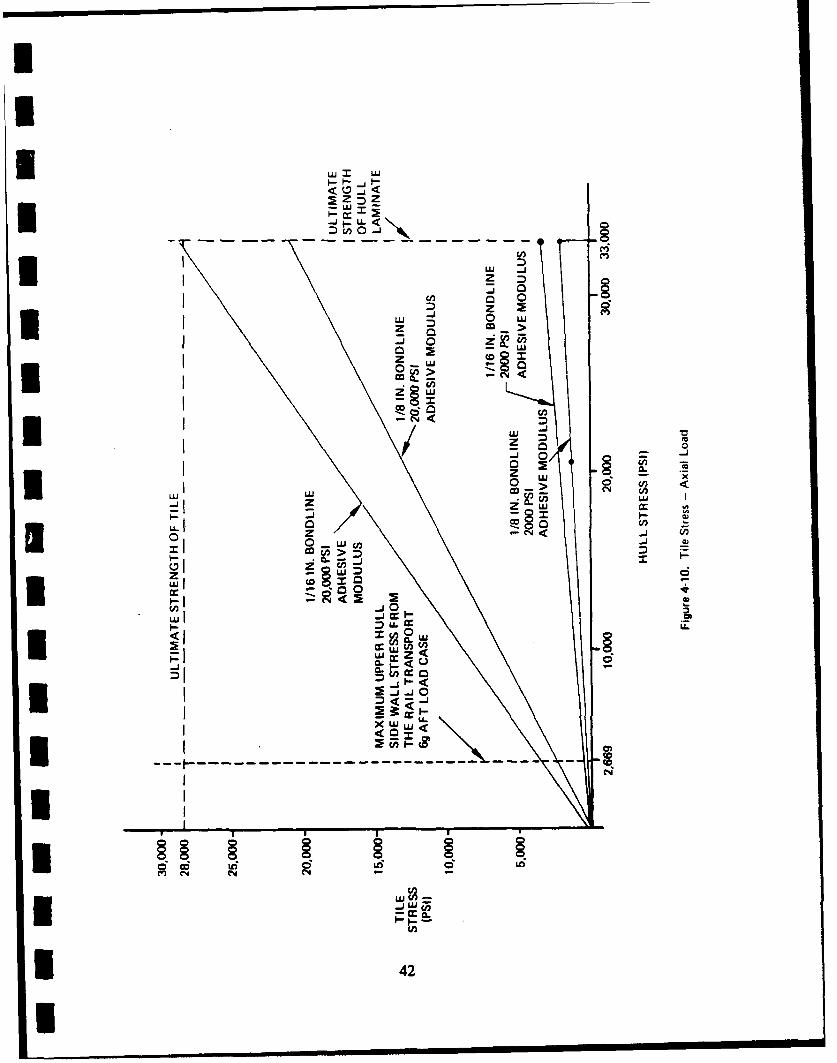
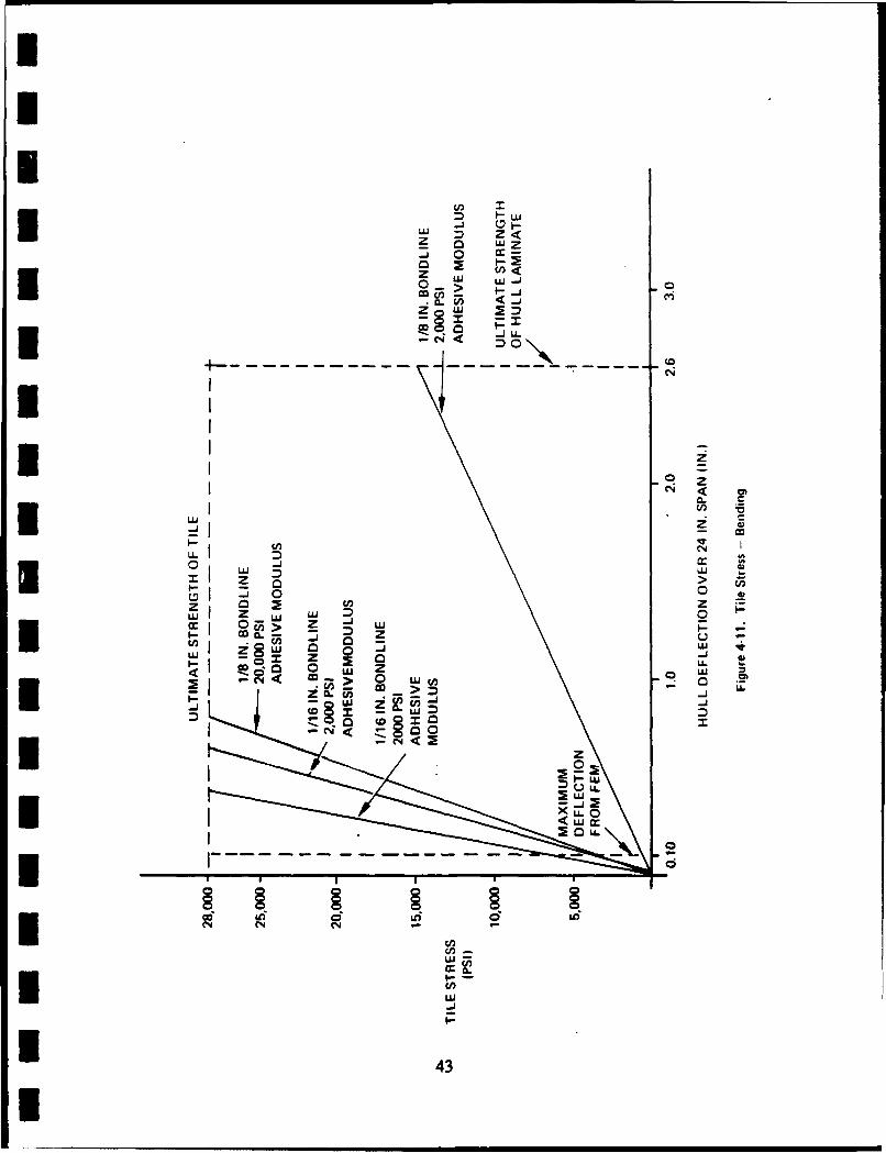
After selection of the 4 inch tile size, further analysis was performed
to determine the effects of bondline thickness and adhesive modulus onthe tile stresses and change in gap spacing. Figures 4-10 and 4-11 showthe effect of bondline thickness and adhesive modulus on tile stress dueto axial and bending loads, respectively. Based on these curves a
maximum adhesive modulus of 20,000 psi (at the lowest design temperature
of -40°F) and minimum bondline thickness of 0.062 inch was selected.These criteria will maintain low tile stresses for all operational
conditions as shown in the curves.
41I
Uu LL
ULI~ D~Z
z 2M >w
0 uj
z*uMK-> ey
c,,
-0 -1
zz wi w
0 > d J <,
0 z
0 LL LLj
zz c,,0
00
*U ccLL
CCO
I 0 6'C'~ N (N(N--
* 42
UL-1 0 W
-h0 ui L
co
zL S0...>
~ -"D
I Cd,
0 J
L C
Z I >
-1
(n(
-
uj z Lu LU cn
0 43w> I-
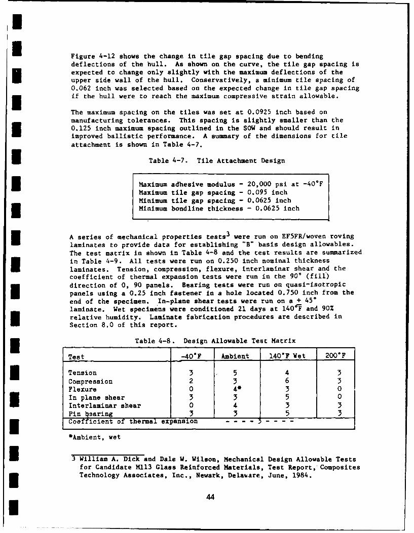
H Figure 4-12 shows the change in tile gap spacing due to bendingdeflections of the hull. As shown on the curve, the tile gap spacing isexpected to change only slightly with the maximum deflections of theupper side wall of the hull. Conservatively, a minimum tile spacing of0.062 inch was selected based on the expected change in tile gap spacingif the hull were to reach the maximum compressive strain allowable.
The maximum spacing on the tiles was set at 0.0925 inch based onmanufacturing tolerances. This spacing is slightly smaller than the0.125 inch maximum spacing outlined in the SOW and should result inimproved ballistic performance. A summary of the dimensions for tile
attachment is shown in Table 4-7.
I Table 4-7. Tile Attachment Design
3 Maximum adhesive modulus - 20,000 psi at -40*FMaximum tile gap spacing - 0.095 inchMinimum tile gap spacing - 0.0625 inchMinimum bondline thickness - 0.0625 inch
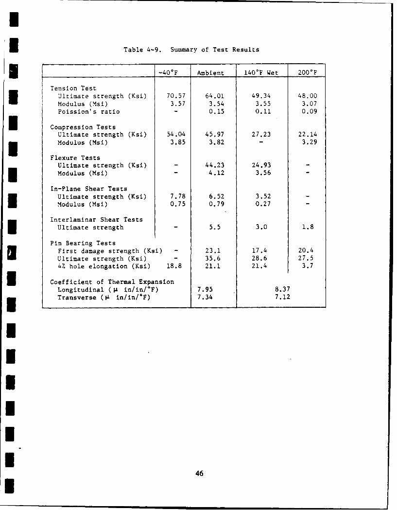
A series of mechanical properties tests 3 were run on EF5FR/woven rovinglaminates to provide data for establishing "B" basis design allowables.The test matrix in shown in Table 4-8 and the test results are summarizedin Table 4-9. All tests were run on 0.250 inch nominal thickness
laminates. Tension, compression, flexure, interlaminar shear and thecoefficient of thermal expansion tests were run in the 90* (fill)
direction of 0, 90 panels. Bearing tests were run on quasi-isotropicpanels using a 0.25 inch fastener in a hole located 0.750 inch from the
end of the specimen. In-plane shear tests were run on a + 450laminate. Wet specimens were conditioned 21 days at 1404F and 90%relative humidity. Laminate fabrication procedures are described inSection 8.0 of this report.
* Table 4-8. Design Allowable Test Matrix
Test -40"F Ambient 140"F Wet 200"F
Tension 3 5 4 3
Compression 2 3 6 3Flexure 0 4* 3 0In plane shear 3 3 5 0Interlaminar shear 0 4 3 3Pin blaring 3 3 5 33 Coefficient of thermal expansion - - - -
*Ambient, wet
3 William A. Dick and Dale W. Wilson, Mechanical Design Allowable Testsfor Candidate M113 Glass Reinforced Materials, Test Report, Composites3 Technology Associates, Inc., Newark, Delaware, June, 1984.
44I

UU
IICL <,
LLU -Jz ~ u=
0 ~w06U)* C-O 00
zLU G
0LUz
000
z
0I
2 w j
00IL 0) 0
I~L ccULU-
UU
I
U Table 4-9. Summary of Test Results
__-40OF Ambient 140OF Wet 200OF
Tension TestUltimate strength (Ksi) 70.57 64.01 49.34 48.00Modulus (Msi) 3.57 3.54 3.55 3.07Poission's ratio - 0.15 0.11 0.09
U Compression TestsUltimate strength (Ksi) 54.04 45.97 27.23 22.14
Modulus (Msi) 3.85 3.82 - 3.29
Flexure TestsUltimate strength (Ksi) - 44.23 24.93 -Modulus (Msi) - 4.12 3.56 -
In-Plane Shear Tests'Ultimate strength (Ksi) 7.78 6.52 3.52 -
Modulus (Msi) 0.75 0.79 0.27 -
Interlaminar Shear TestsUltimate strength - 5.5 3.0 1.8
Pin Bearing TestsFirst damage strength (Ksi) - 23.1 17.4 20.4
Ultimate strength (Ksi) - 35.6 28.6 27.54% hole elongation (Ksi) 18.8 21.1 21.4 3.7
I Coefficient of Thermal ExpansionLongitudinal (g in/in/GF) 7.95 8.37Transverse (L in/in/°F) 7.34 7.12
I
46
I
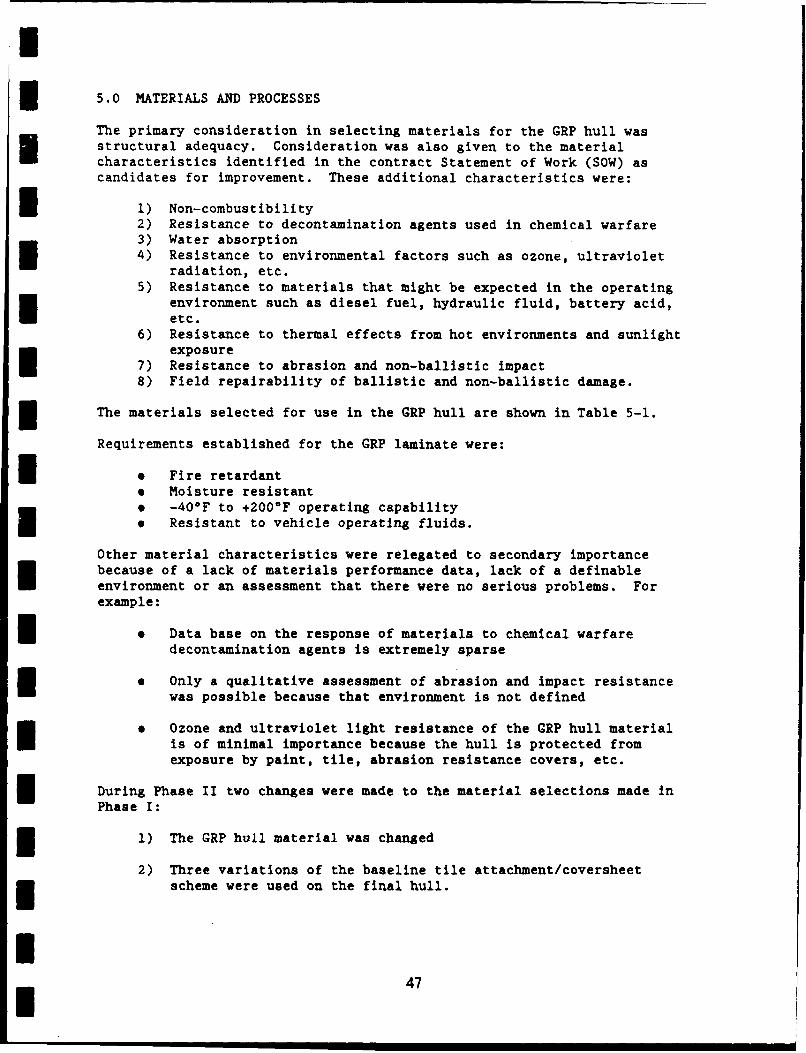
5.0 MATERIALS AND PROCESSES
The primary consideration in selecting materials for the GRP hull wasstructural adequacy. Consideration was also given to the materialcharacteristics identified in the contract Statement of Work (SOW) ascandidates for improvement. These additional characteristics were:
* 1) Non-combustibility2) Resistance to decontamination agents used in chemical warfare3) Water absorption4) Resistance to environmental factors such as ozone, ultraviolet
radiation, etc.5) Resistance to materials that might be expected in the operating
environment such as diesel fuel, hydraulic fluid, battery acid,etc.
6) Resistance to thermal effects from hot environments and sunlightexposure
7) Resistance to abrasion and non-ballistic impact
8) Field repairability of ballistic and non-ballistic damage.
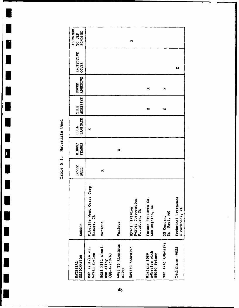
The materials selected for use in the GRP hull are shown in Table 5-1.
Requirements established for the GRP laminate were:
* * Fire retardant* Moisture resistant* -40OF to +2000F operating capabilityI Resistant to vehicle operating fluids.
Other material characteristics were relegated to secondary importancebecause of a lack of materials performance data, lack of a definableenvironment or an assessment that there were no serious problems. Forexample:
* Data base on the response of materials to chemical warfaredecontamination agents is extremely sparse
* Only a qualitative assessment of abrasion and impact resistancewas possible because that environment is not defined
* Ozone and ultraviolet light resistance of the GRP hull materialis of minimal importance because the hull is protected fromexposure by paint, tile, abrasion resistance covers, etc.
During Phase II two changes were made to the material selections made in
Phase I:
1) The GRP hull material was changed
2) Three variations of the baseline tile attachment/coversheet* scheme were used on the final hull.
I
• . , R i l lI I47
0 0
002
CA -4 0
0 Q
o0 4 0" 02, .0 4 0 D
-4 -402 -40 0 In661 02: -0
.06 *4 >. cn
93-a 40
484
Ii
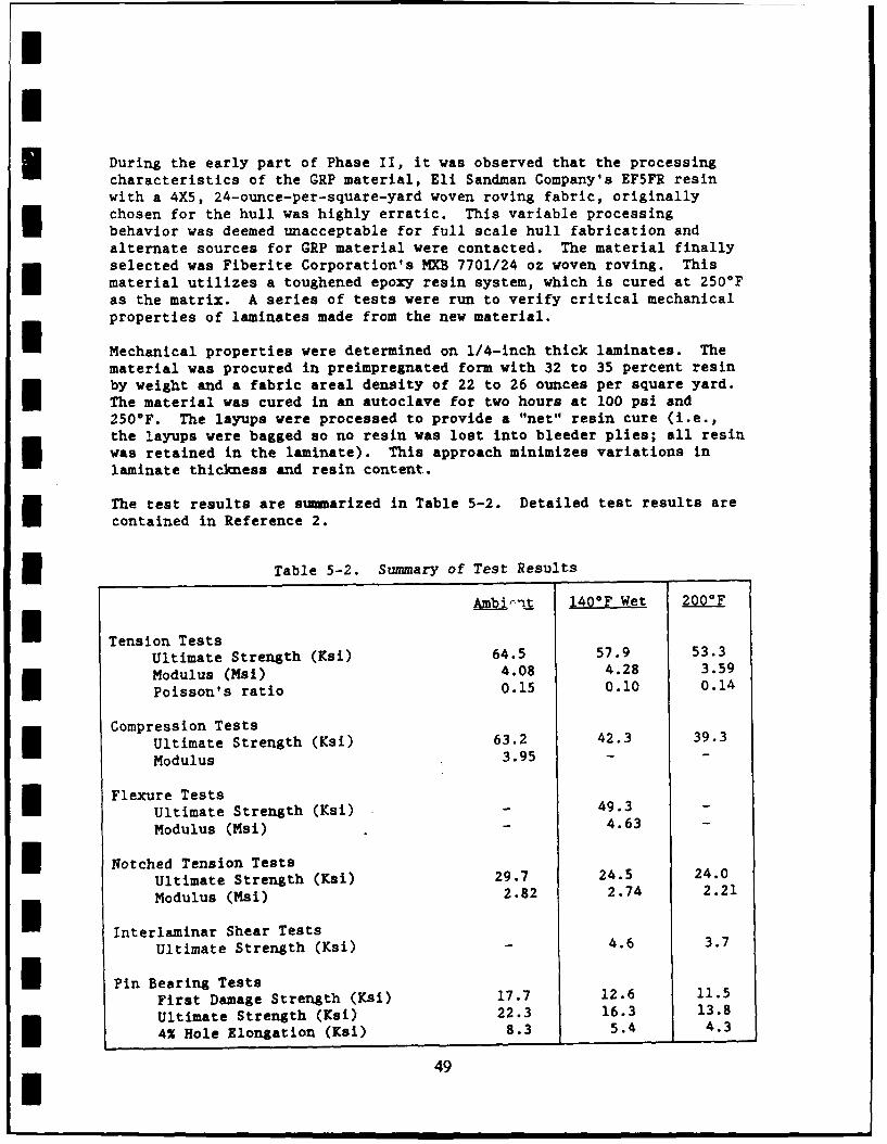
During the early part of Phase II, it was observed that the processingcharacteristics of the GRP material, Eli Sandman Company's EF5FR resin
with a 4X5, 24-ounce-per-square-yard woven roving fabric, originally
chosen for the hull was highly erratic. This variable processing
behavior was deemed unacceptable for full scale hull fabrication andalternate sources for GRP material were contacted. The material finally
selected was Fiberite Corporation's MXB 7701/24 oz woven roving. This
material utilizes a toughened epoxy resin system, which is cured at 2500Fas the matrix. A series of tests were run to verify critical mechanical
properties of laminates made from the new material.
Mechanical properties were determined on 1/4-inch thick laminates. The
material was procured in preimpregnated form with 32 to 35 percent resin
by weight and a fabric areal density of 22 to 26 ounces per square yard.
The material was cured in an autoclave for two hours at 100 psi and2500F. The layups were processed to provide a "net" resin cure (i.e.,
the layups were bagged so no resin was lost into bleeder plies; all resin
was retained in the laminate). This approach minimizes variations in
laminate thickness and resin content.
The test results are summarized in Table 5-2. Detailed test results are
contained in Reference 2.
f Table 5-2. Summary of Test Results
Ambi--t 140OF Wet 200O
H Tension TestsUltimate Strength (Ksi) 64.5 57.9 53.3
Modulus (Msi) 4.08 4.28 3.59
Poisson's ratio 0.15 0.10 0.14
Compression TestsUltimate Strength (Ksi) 63.2 42.3 39.3
Modulus 3.95 - -
Flexure TestsUltimate Strength (Ksi) - 49.3Modulus (Msi) - 4.63 -
I Notched Tension TestsUltimate Strength (Ksi) 29.7 24.5 24.0
Modulus (Msi) 2.82 2.74 2.21
Interlaminar Shear TestsUltimate Strength (Ksi) - 4.6 3.7
i Pin Bearing TestsFirst Damage Strength (Ksi) 17.7 12.6 11.5
Ultimate Strength (Ksi) 22.3 16.3 13.8
4% Hole Elongation (Ksi) 8.3 5.4 4.3
49
I H
I
I Two variations to the baseline tile attachment configuration were addedto the program to obtain producibility and performance data on configura-tions other than the baseline. The Variations were:
0 use of an abrasion resistant polyurethane layer rather thanaluminum as the protective cover on the right (engine) side ofthe hull
* use of a pressure sensitive adhesive to attach the tiles andcover sheets on the rear of the hull.
The urethane cover material was Techthane-90SS, an extremely tough,sprayable, room-temperature curing, polyurethane elastomer manufacturedby Technical Urethanes, Inc., Clearbrook, Virginia. This material wasapplied by spraying directly over tiles that were bonded to the GRP sidewall. The tiles were prepared for spraying by solvent wiping and primingwith Techthane-FC primer. The primer was allowed to dry at roomtemperature for 2 hours prior to applying the urethane elastomer. TheTechthane-90SS coating was sprayed on as a 50 percent solids solutionusing an airless spray gun. The coating was built up in coats about .015inch thick with a drying time of 15 to 20 minutes between coats. Thetotal coating thickness was nominally .062 inch. The properties of roomtemperature cured Techthane-90SS are given in Table 5-3.
Table 5-3. Typical Properties ofTechthane-90SS
I Tensile Strength (ASTM-D412), psi ..................... 4,600Tear Strength (ASTM-D624, Die-C), pli ................. 350
(ASTM-D470, Split), pl ................. 90100% Modulus (ASTM-D414) psi ........................... 1,200Elongation (ASTM-D412), % ............................. 410Hardness, Durometer A ................................. 90Rebound, Bashore, % ................................... 40Adhesion, (ASTM-D429), pl ............................ 70
The other variation in tile attachment was the use of a pressuresensitive adhesive film in place of urethane elastomer. The materialused was 3M Company's VHB 4945, a double coated acrylic foam tape. Theuse of this material allows tiles to be attached to the hull by simplypressing them into place. No cure time or separate adhesive isrequired. The use of a pressure senctive adhesive offers labor savingsin production and has potentia) frr use in rapid field repairs. Theproperties of the VHB-4945 Tapt are summarized in Table 5-4.
I Table 5-4. Performance Characteristics ofVHB 4945 Tape
Peel Adhesion, 90* (lb/in) ........................... 20Normal Tensile Strength (Psi) ......................... 120Shear Strength @ 720F (Psi) .......................... 1,500Shear Strength @ 150OF (Psi) .......................... 500Shear Strength @ 200eF (Psi) .......................... 500
50
IThe tiles selected are the same composition as recommended in the SOW,94% alumina. The Coors Procelain Company's grade AD94 is the specificmaterial selected.
The tile bonding adhesive selected is a two-component room temperaturecuring polyurethane (M&T Chemicals, Inc., Furane Products DivisionUralane 8089). Some properties of this material are summarized in Table5-5. This selection was based primarily on its ability to meet themodulus requirement of 20,000 psi at 40°F (refer to Section 4.0) and itsgood peel strength. A critical unknown about this material is itsresistance to CW decontamination agents, particularly DS2. CWdecontamination agent resistance is not considered critical to thepresent feasibility demonstration, but it is a significant item for anoperational vehicle.
I Table 5-5. Furane 8089 Adhesive Properties
f Temp -40F 72 1400F
Modulus 23,675 psi 1,092 psi 365 psiT-Peel 95 lb/in 42.5 lin --
Elongation 42% 131% 76%Lap Shear 3295 psi 827 psi 410 psi
* Selection of three protective coatings for the material verification testpanels for delivery to DTRC was done on a qualitative basis because noadequate definition of the abrasion/impact environment is available. Thethree selected coatings are:
. Thin (.032 inch) aluminum sheet
I Two-ply style 220 Kevlar 49 fabric/Uralane 8089 polyurethaneelastomer laminate
I . Two-ply style 220 Kevlar 49 fabric/Hysol 9330 toughened epoxyresin laminate.
All of the covers were bonded over the ceramic tiles with a thick ( -.040inch) layer of the Uralane 8089 adhesive.
The protective cover configurations were selected to provide a range ofprotection. The thin aluminum sheet with a thick elastomeric bond lineprovides high abrasion and cut resistance, and because the aluminum isstiff, will distribute impact loads over a wider area than the other twoapproaches, thus reducing stresses on the tiles. The Kevlar/urethanelaminate was chosen as an approach which would act like a rubber pad todissipate impact energy and still have toughness and tear resistanceprovided by the Kevlar reinforcement. The Kevlar/toughened epoxylaminate provides an intermediate protective layer which should bothspread and dissipate impact energy.
I 51I
I
Five panels using each protective cover were fabricated and delivered toDTRC for testing.
All panels were 18 inches square and consisted of the basic 0.75 inchminimum thickness woven roving laminate, 1/2 inch thick 94% aluminaceramic tiles, and the protective cover sheets. To obtain verificationof the selected laminate process, the GRP laminate were prepared as3/4-inch thick, 96-inch by 40-inch panels. The 18-inch square panelswere cut from the large panels. No problems were encountered infabrication the large panels. Nylon tear plies were laid up on bothfaces of the panels and cured in place during the laminate cure. Thoseplies, that are removed just prior to bonding or finishing, protect thelaminate surface from contamination that could interfere with theadhesion of paint or adhesive.
Laminated protective covers were prepared by making a wet layup of twoplies of style 220 Kevlar fabric and a nylon tear ply on an aluminum caulplate. The layups were allowed to cure at room temperature under contactpressure.
Tile bonding and cover sheet bonding were accomplished in the sameprocess. The surfaces of the Kevlar and GRP laminates were prepared forbonding by removing the nylon tear ply. The aluminum cover sheet wasprepared by a sodium dichromate/sulfuric acid etch and the tiles werecleaned by vapor degreasing. The aluminum and tiles were primed withFurane 88060 primer. Precured urethane elastomer spacers were bonded tothe tiles to control tile spacing. The spacers were 0.063 inch thick onthe bottom and sides of the tiles to control tile-to-GRP and tile-to-tilebondline thickness, and 0.040 inch thick at the top of the tiles tocontrol tile-to-cover bondline thickness. Temporary dams were placedaround the periphery of the GRP panels and an excess of Uralane 8089adhesive was poured in the dammed area. The tiles were then pressed intothe uncured adhesive until they bottomed out on the spacers. Then thecover sheet was placed over the tiles and pressed down until it contactedthe spacers on top of the tiles. Excess adhesive was scraped away andthe panels were placed in an oven at 150*F to cure. Preparation forpainting consisted of application of wash primer (DOD-P-15378D) to thealuminum cover sheets and peel ply removal on GRP and Kevlar laminates.The panels were finished coated with MIL-C-46168A polyurethane paint.
On the basis of providing ease of manufacture, the thin aluminum sheetwas selected as the baseline protective cover at the end of Phase I.
The adhesive/sealant selected for the main joint and around the hatchrings, door frames etc., is Dexter Corporation, Hysol Division's Hysol9330, a high strength toughened epoxy. This material provides highstrength plus enough resiliency to accor-modate the deflections occurringat joints and openings.
One key consideration in the selection of materials for amphibiousvehicles is seawater corrosion. Even though the major constructionmaterials selected -- GRP, 5000 series aluminum alloys and 6000 seriesaluminum alloys -- have excellent corrosion resistance, there are stillpotential corrosion problems to be dealt with in joint and fastener
52I
areas. The corrosion problems of concern are: galvanic corrosion,Istress corrosion cracking, and crevice corrosion.he best approach to preventing galvanic corrosion is to use materialsthat are electrochemically compatible such as GRP and aluminum. Thepractical choice of compatible fastener materials is limited to aluminum,titanium and plastic. Because aluminum and plastic fasteners arerelatively low in strength and easily deformed, the fastener material ofchoice for a production hull program is titanium. For this feasibilitydemonstration program, obtaining titanium fasteners in small quantitiesin the sizes needed may present a problem in both cost and schedule. Inthe event that titanium fasteners cannot be obtained, the fall backposition is to use stainless steel fasteners for the feasibilitydemonstration hull. These fasteners would be installed with wet sealantto minimize corrosion. It is believed that the corrosion problemassociated with using stainless steel fasteners can be tolerated for thepresent program, they are not recommended for a production vehicle.Cadmium plated steel fasteners are not used for two reasons.
1) Cadmium has been shown to promote stress corrosion cracking of5083, the aluminum alloy used in the lower hull, in a marine3 environment
2) When the cadmium plating is scraped off the steel by track slap3or other abrasion, the fastener would corrode very rapidly.
Crevice corrosion is a problem in any aluminum structure where cracks orcrevices that seawater can enter exist. In the GRP hull design there arenumerous areas of potential crevice corrosion problems. The approach toeliminating or controlling crevice corrosion is to minimize the openvolume in cracks or crevices by using faying surface sealing, wet3 fastener installation, etc.
IIIIIU
I
I
6.0 FABRICATION
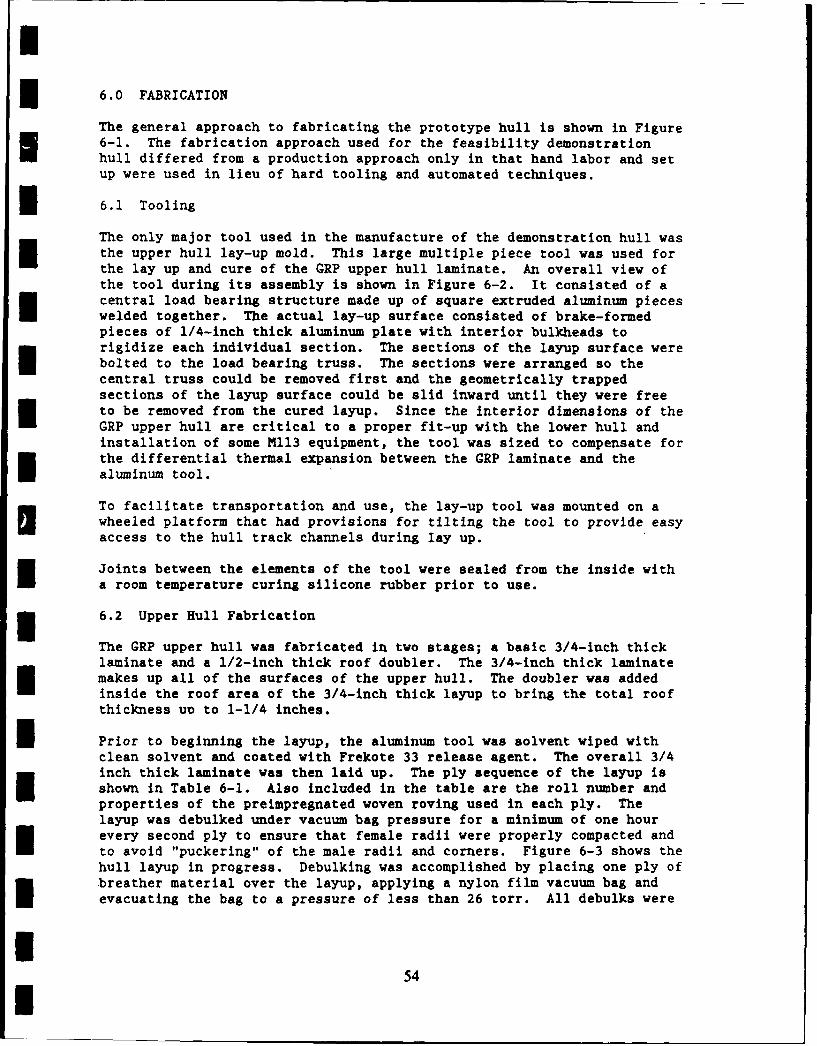
The general approach to fabricating the prototype hull is shown in Figure6-1. The fabrication approach used for the feasibility demonstrationhull differed from a production approach only in that hand labor and setup were used in lieu of hard tooling and automated techniques.
* 6.1 Tooling
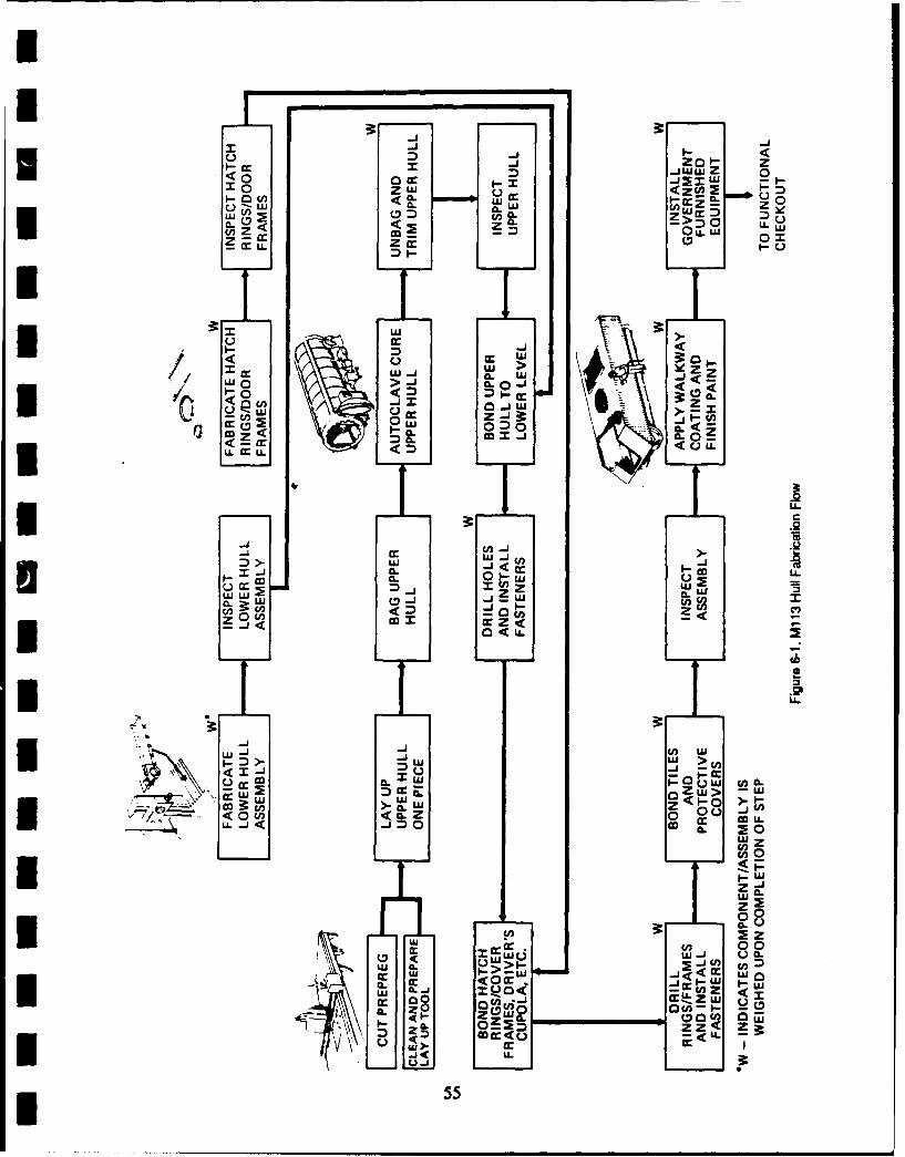
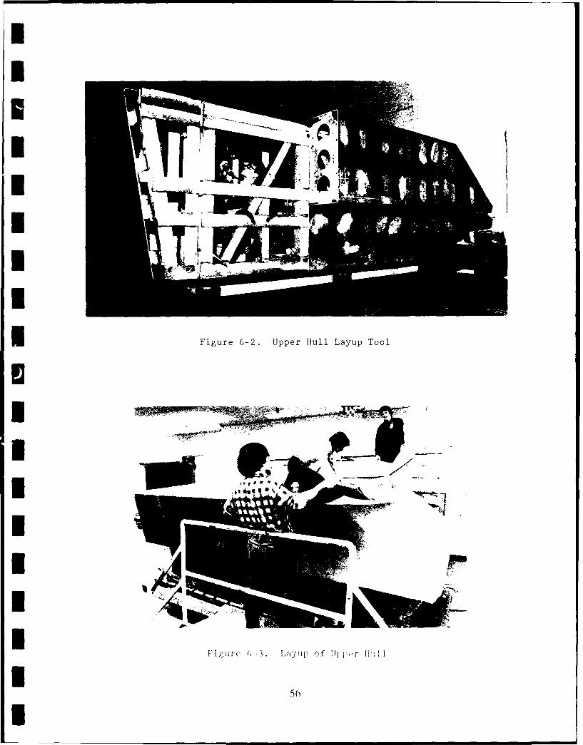
The only major tool used in the manufacture of the demonstration hull wasthe upper hull lay-up mold. This large multiple piece tool was used forthe lay up and cure of the GRP upper hull laminate. An overall view ofthe tool during its assembly is shown in Figure 6-2. It consisted of acentral load bearing structure made up of square extruded aluminum pieceswelded together. The actual lay-up surface consisted of brake-formedpieces of 1/4-inch thick aluminum plate with interior bulkheads torigidize each individual section. The sections of the layup surface werebolted to the load bearing truss. The sections were arranged so thecentral truss could be removed first and the geometrically trappedsections of the layup surface could be slid inward until they were freeto be removed from the cured layup. Since the interior dimensions of theGRP upper hull are critical to a proper fit-up with the lower hull andinstallation of some M113 equipment, the tool was sized to compensate forthe differential thermal expansion between the GRP laminate and thealuminum tool.
To facilitate transportation and use, the lay-up tool was mounted on awheeled platform that had provisions for tilting the tool to provide easyaccess to the hull track channels during lay up.
Joints between the elements of the tool were sealed from the inside witha room temperature curing silicone rubber prior to use.
* 6.2 Upper Hull Fabrication
The GRP upper hull was fabricated in two stages; a basic 3/4-inch thicklaminate and a 1/2-inch thick roof doubler. The 3/4-inch thick laminatemakes up all of the surfaces of the upper hull. The doubler was addedinside the roof area of the 3/4-inch thick layup to bring the total roofthickness uD to 1-1/4 inches.
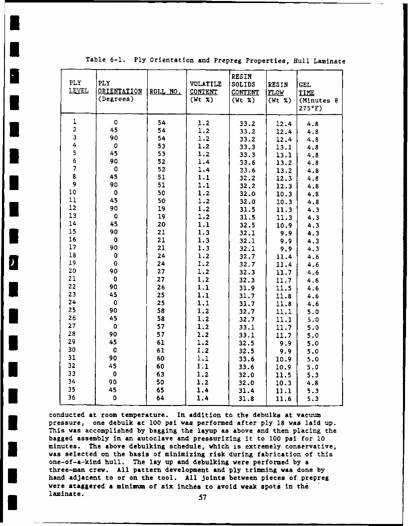
I Prior to beginning the layup, the aluminum tool was solvent wiped withclean solvent and coated with Frekote 33 release agent. The overall 3/4inch thick laminate was then laid up. The ply sequence of the layup isshown in Table 6-1. Also included in the table are the roll number andproperties of the preimpregnated woven roving used in each ply. Thelayup was debulked under vacuum bag pressure for a minimum of one hourevery second ply to ensure that female radii were properly compacted andto avoid "puckering" of the male radii and corners. Figure 6-3 shows thehull layup in progress. Debulking was accomplished by placing one ply ofbreather material over the layup, applying a nylon film vacuum bag andevacuating the bag to a pressure of less than 26 torr. All debulks were
54I
Ir <0 zL)<CLa i w ES: 00o
*nZ e0z L. .
DIw>0<
:)I- c 0 C..< ( xa Lw
Lh
3:.2
~~..2
w1 CfO nIj .j 2 1 -
CL : W0 z mu.C
< -00 < C0
a..
-J a.-UJJ> U5 I._,U
L)< CCc . UlC )C*J2: :zUII 55L U -
IIIIUIIII Figure 6-2. Upper Hull Layup Tool
U3IIIIIII
96
I
mU
Table 6-1. Ply Orientation and Prepreg Properties, Hull Laminatel RESIN
PLY PLY VOLATILE SOLIDS RESIN GELLEVEL ORIENTATION ROLL NO. CONTENT CONTENT FLOW TIME
(Degrees) (Wt %) (Wt %) (Wt %) (Minutes @
I 2750F)1 0 54 1.2 33.2 12.4 4.82 45 54 1.2 33.2 12.4 4.83 90 54 1.2 33.2 12.4 4.84 0 53 1.2 33.3 13.1 4.85 45 53 1.2 33.3 13.1 4.86 90 52 1.4 33.6 13.2 4.87 0 52 1.4 33.6 13.2 4.88 45 51 1.1 32.2 12.3 4.89 90 51 1.1 32.2 12.3 4.8
10 0 50 1.2 32.0 10.3 4.811 45 50 1.2 32.0 10.3 4.812 90 19 1.2 31.5 11.3 4.313 0 19 1.2 31.5 11.3 4.314 45 20 1.1 32.5 10.9 4.315 90 21 1.3 32.1 9.9 4.316 0 21 1.3 32.1 9.9 4.317 90 21 1.3 32.1 9.9 4.3
18 0 24 1.2 32.7 11.4 4.619 0 24 1.2 32.7 11.4 4.620 90 27 1.2 32.3 11.7 4.621 0 27 1.2 32.3 11.7 4.622 90 26 1.1 31.9 11.5 4.623 45 25 1.1 31.7 11.8 4.624 0 25 1.1 31.7 11.8 4.625 90 58 1.2 32.7 11.1 5.026 45 58 1.2 32.7 11.1 5.027 0 57 1.2 33.1 11.7 5.028 90 57 1.2 33.1 11.7 5.029 45 61 1.2 32.5 9.9 5.030 0 61 1.2 32.5 9.9 5.031 90 60 1.1 33.6 10.9 5.032 45 60 Ioi 33.6 10.9 5.033 0 63 1.2 32.0 11.5 5.334 90 50 1.2 32.0 10.3 4.835 45 65 1.4 31.4 12.1 5.336 0 64 1.4 31.8 11.6 5.3
conducted at room temperature. In addition to the debulks at vacuumpressure, one debulk at 100 psi was performed after ply 18 was laid up.This was accomplished by bagging the layup as above and then placing thebagged assembly in an autoclave and pressurizing it to 100 psi for 10minutes. The above debulking schedule, which is extremely conservative,was selected on the basis of minimizing risk during fabrication of thisone-of-a-kind hull. The lay up and debulking were performed by athree-man crew. All pattern development and ply trimming was done byhand adjacent to or on the tool. All joints between pieces of prepregwere staggered a minimum of six inches to avoid weak spots in the-laminate. 57
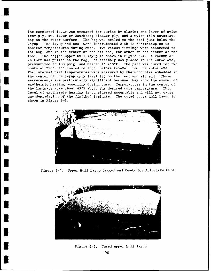
I
The completed layup was prepared for curing by placing one layer of nylontear ply, one layer of Mauchberg bleeder ply, and a nylon film autoclave
bag on the outer surface. The bag was sealed to the tool just below thelayup. The layup and tool were instrumented with 12 thermocouples tomonitor temperatures during cure. Two vacuum fittings were connected to
the bag, one in the center of the aft end, the other in the center of the
roof. The bagged upper hull layup is shown in Figure 6-4. A vacuum of
26 torr was pulled on the bag, the assembly was placed in the autoclave,
pressurized to 100 psig, and heated to 250 0 F. The part was cured for twohours at 250F and cooled to 150F before removal from the autoclave.The internal part temperatures were measured by thermocouples embedded in
the center of the layup (ply level 18) on the roof and aft end. Thesemeasurements are particularly significant because they show the amount of
exothermic heating occurring during cure. Temperatures in the center ofthe laminate rose about 45°F above the desired cure temperature. This
level of exothermic heating is considered acceptable and will not cause
any degradation of the finished laminate. The cured upper hull layup is
shown in Figure 6-5.
Figure 6-4. Upper Hull Layup Bagged and Ready for Autoclave Cure
Figure 6-5. Cured upper hull layup
58
I .. .. _
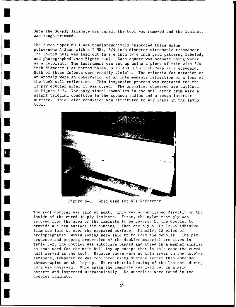
I
UOnce the 36-ply laminate was cured, the tool was removed and the laminatewas rough trimmed.
The cured upper hull was nondistructively inspected twice usingpulse-echo A-Scan with a 1 MHz, 3/4-inch diameter ultrasonic transducer.The 36-ply hull was laid out in a 6 inch by 6 inch grid pattern, labeled,and photographed (see Figure 6-6). Each square was scanned using water
as a couplant. The instrument was set up using a piece of trim with 3/8inch diameter flat bottom holes, 0.25 and 0.50 inch deep as a standard.Both of these defects were readily visible. The criteria for notation ofan anomaly were an observation of an intermediate reflection or a loss ofthe back wall reflection. This inspection process was repeated for the18 ply doubler after it was cured. The anomalies observed are outlinedin Figure 6-7. The only visual anomolies in the hull after trim were aslight bridging condition in the sponson radius and a rough interiorsurface. This later condition was attributed to air leaks in the layup
I tool.UI
Figure 6-6. Grid used for NDI Reference
The roof doubler was laid up next. This was accomplished directly on the
inside of the cured 36-ply laminate. First, the nylon tear ply wasremoved from the area of the laminate to be covered by the doubler toprovide a clean surface for bonding. Then one ply of FM 125-5 adhesivefilm was laid up over the prepared surface. Finally, 18 plies of
preimpregnated woven roving were laid up to form the doubler. The plysequence and prepreg properties of the doubler material are given inTable 6-2. The doubler was autoclave bagged and cured in a manner similarto that used for the main hull lay up except that in this case the curedhull served as the tool. Because there were no trim areas on the doublerlaminate, temperature was monitored using surface rather than embedded
themocouples on the lay up. No exothermic heating of the laminate duringcure was observed. Once again the laminate was laid out in a gridpattern and inspected ultrasonically. No anomolies were found in the
i doubler laminate.
59I
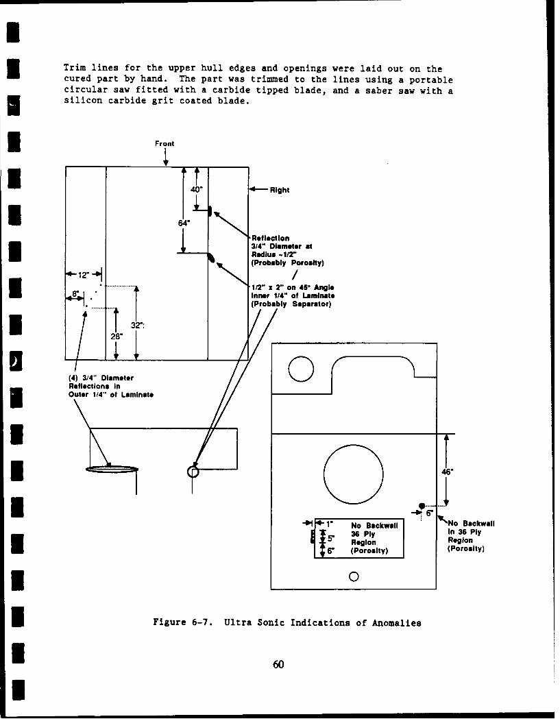
Trim lines for the upper hull edges and openings were laid out on thecured part by hand. The part was trimmed to the lines using a portablecircular saw fitted with a carbide tipped blade, and a saber saw with asilicon carbide grit coated blade.
Front
4--Right
6Reflection
3/4" Diameter atRadius -1/r'(Probably Porosity)
12-/1/2" x2" on 45" AngieInner 1/4" of Laminate
... (Probably Separator)
32":
(4) 3/4" Diameteri Reflections In
Outer 1/4" at Laminate
* 4 8", .°w,
4 1. No lackwall No Backwall
36 Ply in 36 Piy5 Region Region
(Porosity) (Porosity)
* 0
I Figure 6-7. Ultra Sonic Indications of Anomalies
U60
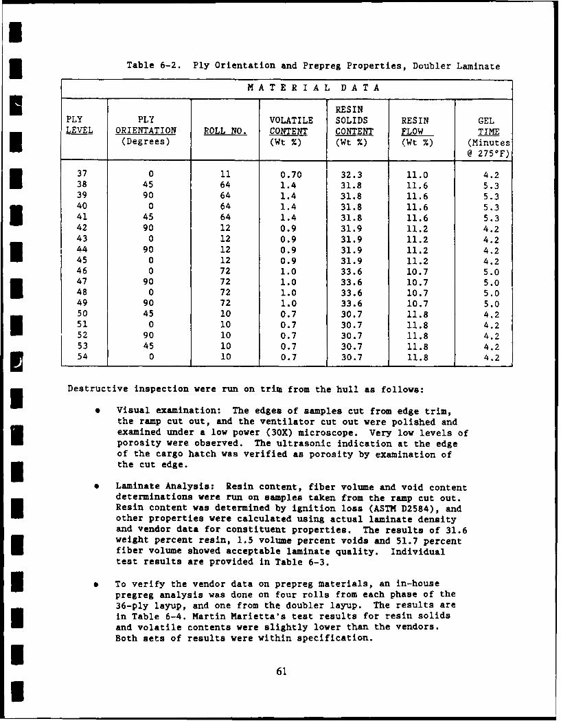
UTable 6-2. Ply Orientation and Prepreg Properties, Doubler Laminate
MATERIAL DATA
* RESINPLY PLY VOLATILE SOLIDS RESIN GELLEVEL ORIENTATION ROLL NO. CONTENT CONTENT FLOW TIME
(Degrees) (Wt %) (Wt %) (Wt %) (Minutes@ 2750F)
37 0 11 0.70 32.3 11.0 4.238 45 64 1.4 31.8 11.6 5.339 90 64 1.4 31.8 11.6 5.340 0 64 1.4 31.8 11.6 5.341 45 64 1.4 31.8 11.6 5.3
42 90 12 0.9 31.9 11.2 4.243 0 12 0.9 31.9 11.2 4.244 90 12 0.9 31.9 11.2 4.245 0 12 0.9 31.9 11.2 4.2
46 0 72 1.0 33.6 10.7 5.047 90 72 1.0 33.6 10.7 5.048 0 72 1.0 33.6 10.7 5.049 90 72 1.0 33.6 10.7 5.050 45 10 0.7 30.7 11.8 4.251 0 10 0.7 30.7 11.8 4.2
52 90 10 0.7 30.7 11.8 4.253 45 10 0.7 30.7 11.8 4.2
S54 0 10 0.7 30.7 11.8 4.2
Destructive inspection were run on trim from the hull as follows:
* Visual examination: The edges of samples cut from edge trim,the ramp cut out, and the ventilator cut out were polished andexamined under a low power (30X) microscope. Very low levels ofporosity were observed. The ultrasonic indication at the edgeof the cargo hatch was verified as porosity by examination ofthe cut edge.
• Laminate Analysis: Resin content, fiber volume and void contentdeterminations were run on samples taken from the ramp cut out.Resin content was determined by ignition loss (ASTM D2584), andother properties were calculated using actual laminate densityand vendor data for constituent properties. The results of 31.6weight percent resin, 1.5 volume percent voids and 51.7 percentfiber volume showed acceptable laminate quality. Individualtest results are provided in Table 6-3.
* To verify the vendor data on prepreg materials, an in-housepregreg analysis was done on four rolls from each phase of the36-ply layup, and one from the doubler layup. The results arein Table 6-4. Martin Marietta's test results for resin solidsand volatile contents were slightly lower than the vendors.Both sets of results were within specification.
I61I
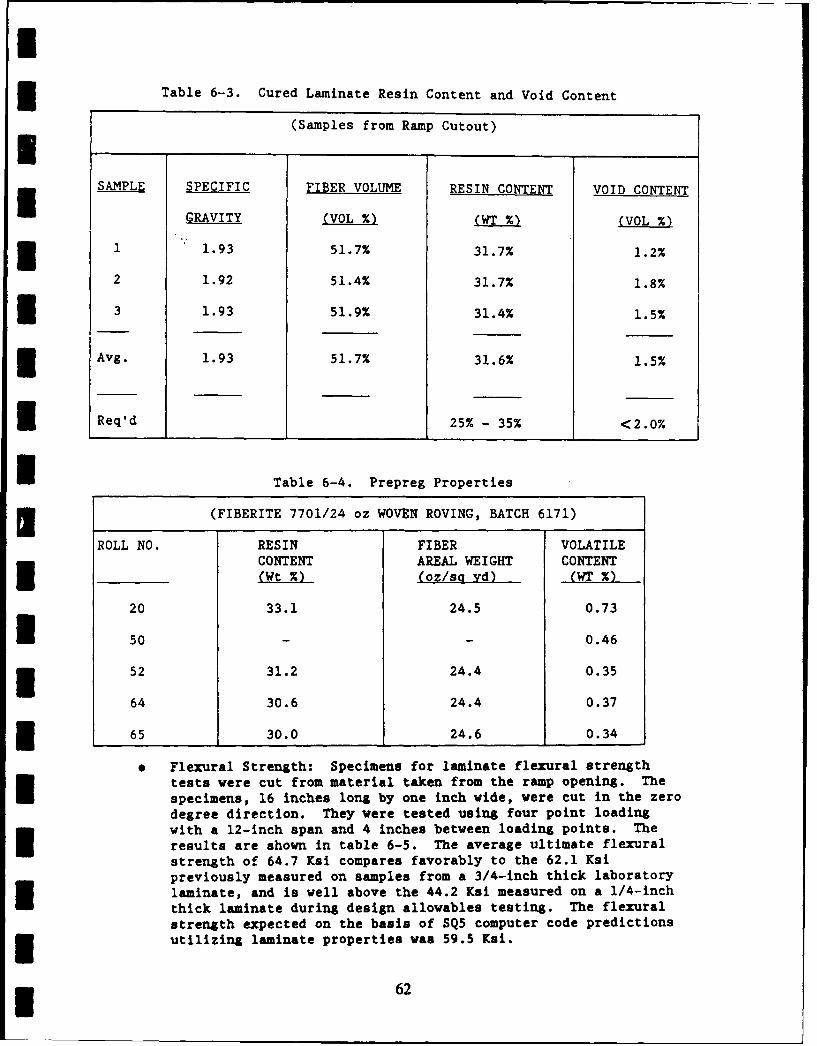
ITable 6-3. Cured Laminate Resin Content and Void Content
(Samples from Ramp Cutout)USAMPLE SPECIFIC FIBER VOLUME RESIN CONTENT VOID CONTENT
GRAVITY (VOL %) (WT %) (VOL %)
3 1 1.93 51.7% 31.7% 1.2%
2 1.92 51.4% 31.7% 1.8%
3 1.93 51.9% 31.4% 1.5%
Avg. 1.93 51.7% 31.6% 1.5%
Req'd 25% - 35% <2.0%
I Table 6-4. Prepreg Properties
(FIBERITE 7701/24 oz WOVEN ROVING, BATCH 6171)
ROLL NO. RESIN FIBER VOLATILECONTENT AREAL WEIGHT CONTENT(Wt %) (oz/so yd) (WT %)
20 33.1 24.5 0.73
1 50 - 0.46
52 31.2 24.4 0.35
64 30.6 24.4 0.37
1 65 30.0 24.6 0.34
. Flexural Strength: Specimens for laminate flexural strengthtests were cut from material taken from the ramp opening. Thespecimens, 16 inches long by one inch wide, were cut in the zerodegree direction. They were tested using four point loadingwith a 12-inch span and 4 inches between loading points. The
results are shown in table 6-5. The average ultimate flexuralstrength of 64.7 Ksi compares favorably to the 62.1 Ksipreviously measured on samples from a 3/4-inch thick laboratorylaminate, and is well above the 44.2 Ksi measured on a 1/4-inch
thick laminate during design allowables testing. The flexural
strength expected on the basis of SQ5 computer code predictionsutilizing laminate properties was 59.5 Ksi.
* 62
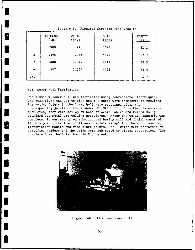
Table 6-5. Flexural Strength Test Results
THICKNESS WIDTH LOAD STRESS(in.) (i . (ksi)
1 .900 .991 4094 61.2
2 .896 .988 4474 67.7
3 .888 1.049 4518 65.5
4 .887 1.054 4452 64.4
Avg. 64.7
6.3 Lower Hull Fabrication
The aluminum lower hull was fabricated using conventional techniques.The 5083 plate was cut to size and the edges were chamfered as required.The welded joints in the lower hull were patterned after thecorresponding joints of the standard MII3Al hull. Once the plates werechamfered, they were set up by hand on acorn tables and welded usingstandard gas metal arc welding procedures. After the welded assembly wascomplete, it was set up on a horizontal boring mill and finish machined.At this point, the lower hull was complete except for the motor mounts,transmission mounts and ramp hinge points. All welds were performed bycertified welders and the welds were subjected to visual inspection. Thecomplete lower hull is shown in Figure 6-8.
Figure 6-8. Aluminum Lower Hull
I 63
I
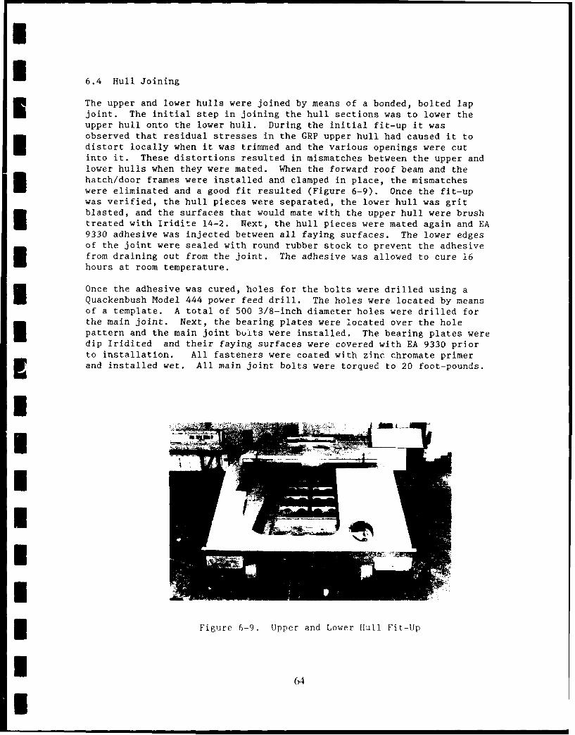
* 6.4 Hull Joining
The upper and lower hulls were joined by means of a bonded, bolted lapjoint. The initial step in joining the hull sections was to lower theupper hull onto the lower hull. During the initial fit-up it wasobserved that residual stresses in the GRP upper hull had caused it todistort locally when it was trimmed and the various openings were cutinto it. These distortions resulted in mismatches between the upper andlower hulls when they were mated. When the forward roof beam and thehatch/door frames were installed and clamped in place, the mismatches
were eliminated and a good fit resulted (Figure 6-9). Once the fit-upwas verified, the hull pieces were separated, the lower hull was gritblasted, and the surfaces that would mate with the upper hull were brushtreated with Iridite 14-2. Next, the hull pieces were mated again and EA9330 adhesive was injected between all faying surfaces. The lower edgesof the joint were sealed with round rubber stock to prevent the adhesivefrom draining out from the joint. The adhesive was allowed to cure 16hours at room temperature.
Once the adhesive was cured, holes for the bolts were drilled using aQuackenbush Model 444 power feed drill. The holes were located by meansof a template. A total of 500 3/8-inch diameter holes were drilled forthe main joint. Next, the bearing plates were located over the holepattern and the main joint buits were installed. The bearing plates weredip Iridited and their faying surfaces were covered with EA 9330 priorto installation. All fasteners were coated with zinc chromate primerand installed wet. All main joint bolts were torqued to 20 foot-pounds.
I
i _
il Figure 6-9. Upper and Lower Ifull Fit-Up
I(A
I* 6.5 Hull Assembly
The hatch and door frames were installed in a manner similar to that usedfor the main joint. The aluminum frames were degreased and treated withIridite 14-2. The faying surfaces of the GRP were prepared by peelingoff the nylon tear ply. The faying surfaces of both parts were coatedwith EA 9330 adhesive, the frames were installed, clamped in place andthe adhesive was allowed to cure at room temperature. Next, holes weredrilled for bolts. The bolt holes were hand drilled using pilot holes inthe frames as guidance. Finally, the bearing plates and bolts wereinstalled and torqued to 20 foot-pounds.
Next, heavily loaded brackets needed for equipment attached to the upperhull were installed. These consisted of brackets for the fuel tank,seats, driver's controls and other brackets that could be heavily loadedin service. The general procedure was to drill through holes in the hulland bolt and bond the brackets in place in a manner similar to that usedfl for the hatch rings.
The next item installed was the engine bulkhead. The bulkhead was builtup of formed 1/4-inch thick aluminum plate. It was essentially identicalto the standard M113 bulkhead. The bulkhead was attached by welding itto the aluminum lower hull, driver's hatch plate and roof beam. In areaswhere it contacted the GRP upper hull, the bulkhead was riveted toaluminum angles, which were bolted to the hull. All mechanicalattachment areas were sealed with MIL-S-8802 sealant to ensure thatengine compartment gases would not leak into the crew compartment. Thefinal interior installations were lightly loaded items such as theinterior lights, fire extinguishers, battery box, etc. Attachments veremade by using expanding threaded inserts installed into holes drilledinto the GRP laminate.
Next, the vertical edge guard fenders and the track shroud attachmentbars were installed. The edge guards were attached using expandingthreaded inserts in holes drilled into the GRP, while the track shroudmounting strips used custom made through hull nuts. The fenders wereattached using bolts and a combination of the above inserts. The hull isshown during assembly in Figures 6-10 and 6-11.
At this point, the hull was complete except for the ceramic tiles and theedge closeouts around the periphery of the tile covered areas.
I 6.6 Tile Installation
Three variations of the basic ceramic armor were installed on the hull:
* On the left (driver's) side and front, tiles with a 0.030-inchthick aluminum zoversheet were used
* On the right (engine) side, no coversheet was us-d and the tileswere covered with an abrasion resistant urethane elastomer layer
*about 1/16-inch thick
I
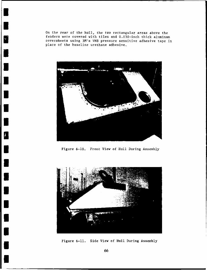
Ii
On the rear of the hull, the two rectangular areas above thefenders were covered with tiles and 0.030-inch thick aluminumcoversheets using 3M's VHB pressure sensitive adhesive tape inplace of the baseline urethane adhesive.I
U --
Figure 6-10. Front View of Hull During Assembly
.66
U b
g Figure 6-11. Sidet View of Hull During Assembly
i6
I
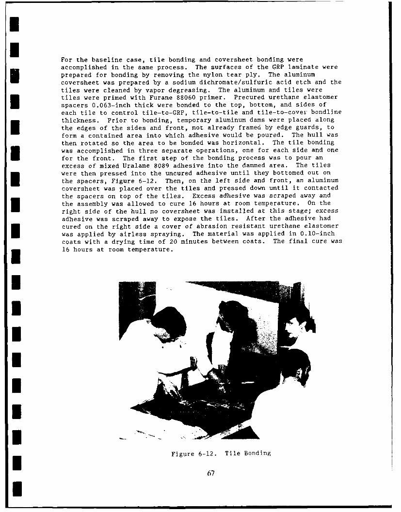
II
For the baseline case, tile bonding and coversheet bonding wereaccomplished in the same process. The surfaces of the GRP laminate wereprepared for bonding by removing the nylon tear ply. The aluminumcoversheet was prepared by a sodium dichromate/sulfuric acid etch and thetiles were cleaned by vapor degreasing. The aluminum and tiles weretiles were primed with Furane 88060 primer. Precured urethane elastomerspacers 0.063-inch thick were bonded to the top, bottom, and sides ofeach tile to control tile-to-GRP, tile-to-tile and tile-to-covei bondlinethickness. Prior to bonding, temporary aluminum dams were placed alongthe edges of the sides and front, not already framed by edge guards, toform a contained area into which adhesive would be poured. The hull wasthen rotated so the area to be bonded was horizontal. The tile bondingwas accomplished in three separate operations, one for each side and onefor the front. The first step of the bonding process was to pour anexcess of mixed Uralane 8089 adhesive into the dammed area. The tileswere then pressed into the uncured adhesive until they bottomed out on
the spacers, Figure 6-12. Then, on the left side and front, an aluminumcoversheet was placed over the tiles and pressed down until it contactedthe spacers on top of the tiles. Excess adhesive was scraped away andthe assembly was allowed to cure 16 hours at room temperature. On the
right side of the hull no coversheet was installed at this stage; excessadhesive was scraped away to expose the tiles. After the adhesive hadcured on the right side a cover of abrasion resistant urethane elastomer
was applied by airless spraying. The material was applied in 0.10-inchcoats with a drying time of 20 minutes between coats. The final cure was
n 16 hours at room temperature.
I
Figure 6-12. Tile Bonding
67I
The tiles for the aft end of the hull were made up into subassembliesthat were then installed on the hull. The first step was to cut a0.030-inch thick piece of aluminum sheet the size of the area to becovered. The sheet was then vapor degreased and a layer of the VHBadhesive was applied to one side of it. Next, tiles, that had theiredges covered with VHB tape, were placed on the VHB tape covered side ofthe coversheet. When the tile array was complete, the exposed side ofthe tiles was covered with a layer of VHB tape and the array was pressedin place on the hull.
When the tile installation was complete, aluminum edge protectors wereinstalled over any exposed tile edges. The edge protectors were attachedto the hull with number 10 screws and sealed to the tiled surfaces with afillet of MIL-S-8802 polysulfide sealant.
The bonded tile arrays were inspected visually, ultrasonically, and bytapping. Some blisters were found between the aluminum cover sheets andthe tiles on the front and left hand side of the hull. Ultrasonicinspection to confirm the tapping results were run using 10 MHz pulseecho contact testing. The ultrasonic indications confirmed the previousresults but were generally 1/2 to 1 inch smaller in size. Notile-to-hull bondline defects were detected in any other area of the hull.
I The blisters were repaired by drilling holes through the cover sheets inthe blisters and injecting 8089 adhesive into the blistered area andallowing it to cure at room temperature. Inspection after repair showedsome debonded areas were still present. Efforts to inject additionaladhesive into these areas were not successful. The vehicle was shipped
with these debonds present.
The hull was prepared for painting by grit blasting. One coat of zincchrommate primer was applied to all surfaces. The interior of the hullwas finish-coated with epoxy enamel, and the exterior was finished wiLhpolyurethane enamel (MIL-C-46168A).
6.7 Equipment Installation
Equipment installations in the composite hull were, with only a fewexceptions, identical to those in the standard Mll3A1. The exceptionswere: use of threaded inserts to attach support clips for wiringharnessess to the GRP, the addition of wires to ground electricalequipment attached to GRP, installation of lifting eyes by boltingthrough the hull, and minor rerouting of the engine compartment fire
* extinguisher plumbing.
The completed vehicle is shown in Figure 6-13.
I68I
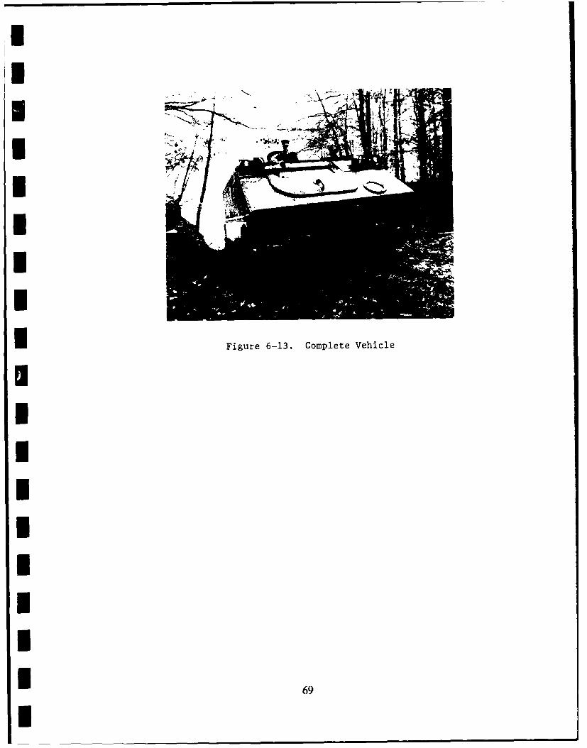
I
nn
ImIi
H Figure 6-13. Complete Vehicle
IIIIII
~69
I
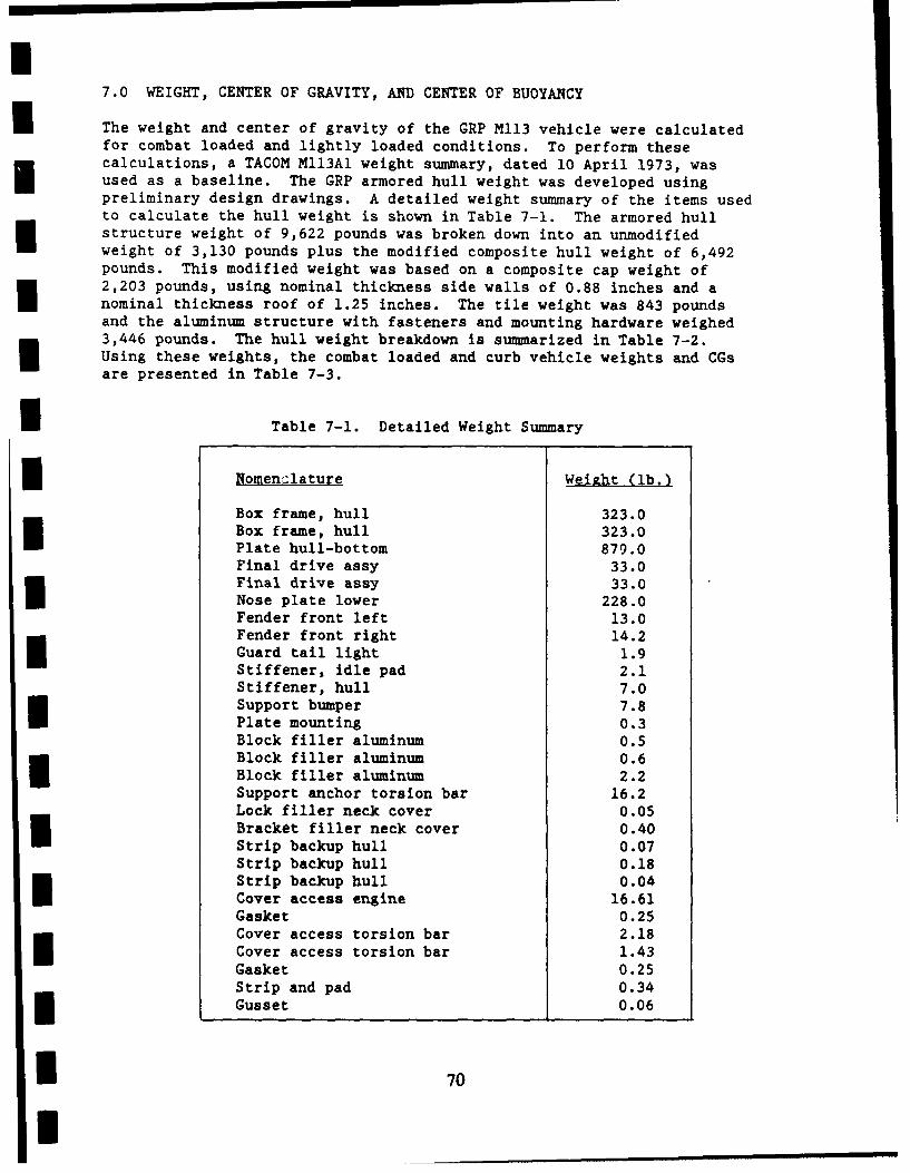
7.0 WEIGHT, CENTER OF GRAVITY, AND CENTER OF BUOYANCY
The weight and center of gravity of the GRP M113 vehicle were calculatedfor combat loaded and lightly loaded conditions. To perform thesecalculations, a TACOM Ml13Al weight summary, dated 10 April 1973, wasused as a baseline. The GRP armored hull weight was developed usingpreliminary design drawings. A detailed weight summary of the items usedto calculate the hull weight is shown in Table 7-1. The armored hullstructure weight of 9,622 pounds was broken down into an unmodifiedweight of 3,130 pounds plus the modified composite hull weight of 6,492pounds. This modified weight was based on a composite cap weight of2,203 pounds, using nominal thickness side walls of 0.88 inches and aInominal thickness roof of 1.25 inches. The tile weight was 843 poundsand the aluminum structure with fasteners and mounting hardware weighed3,446 pounds. The hull weight breakdown is summarized in Table 7-2.Using these weights, the combat loaded and curb vehicle weights and CGsare presented in Table 7-3.
Table 7-1. Detailed Weight Summary
Nomenclature Weight (lb.)
Box frame, hull 323.0Box frame, hull 323.0Plate hull-bottom 879.0Final drive assy 33.0Final drive assy 33.0Nose plate lower 228.0Fender front left 13.0Fender front right 14.2Guard tail light 1.9Stiffener, idle pad 2.1Stiffener, hull 7.0Support bumper 7.8Plate mounting 0.3Block filler aluminum 0.5Block filler aluminum 0.6Block filler aluminum 2.2Support anchor torsion bar 16.2Lock filler neck cover 0.05Bracket filler neck cover 0.40Strip backup hull 0.07Strip backup hull 0.18Strip backup hull 0.04
Cover access engine 16.61Gasket 0.25Cover access torsion bar 2.18Cover access torsion bar 1.43Gasket 0.25Strip and pad 0.34Gusset 0.06
70I 7
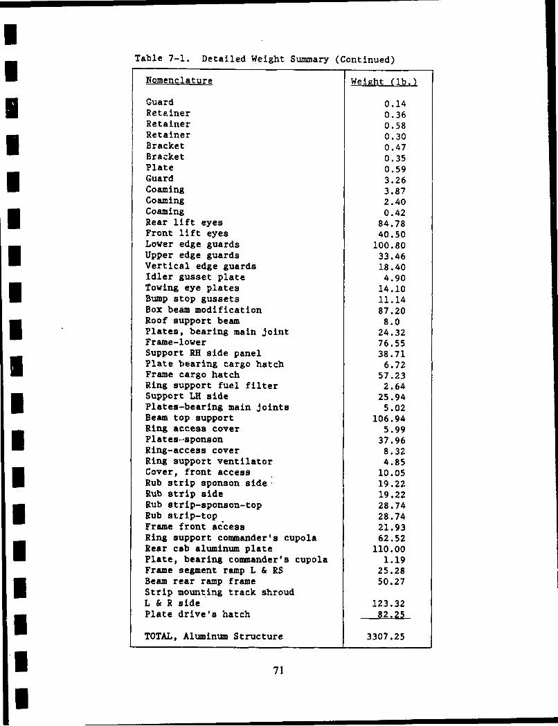
Table 7-1. Detailed Weight Summary (Continued)
Nomenclature Weight (lb.)
Guard 0.14Retainer 0.36Retainer 0.58Retainer 0.30Bracket 0.47Bracket 0.35Plate 0.59
Guard 3.26Coaming 3.87Coaming 2.40Coaming 0.42Rear lift eyes 84.78Front lift eyes 40.50Lower edge guards 100.80Upper edge guardsVertical edge guards 18.40Idler gusset plate 4.90Towing eye plates 14.10Bump stop gussets 11.14Box beam modification 87.20Roof support beam 8.0Plates, bearing main joint 24.32Frame-lower 76.55Support RH side panel 38.71Plate bearing cargo hatch 6.72Frame cargo hatch 57.23Ring support fuel filter 2.64Support LH side 25.94Plates-bearing main joints 5.02Beam top support 106.94Ring access cover 5.99Plates-sponson 37.96Ring-access cover 8.32Ring support ventilator 4.85Cover, front access 10.05Rub strip sponson side. 19.22Rub strip side 19.22Rub strip-sponson-top 28.74Rub strip-top 28.74Frame front access 21.93Ring support commander's cupola 62.52Rear cab aluminum plate 110.00Plate, bearing commander's cupola 1.19Frame segment ramp L & RS 25.28Beam rear ramp frame 50.27Strip mounting track shroudL & R side 123.32Plate drive's hatch 82.25
TOTAL, Aluminum Structure 3307.25
71
U
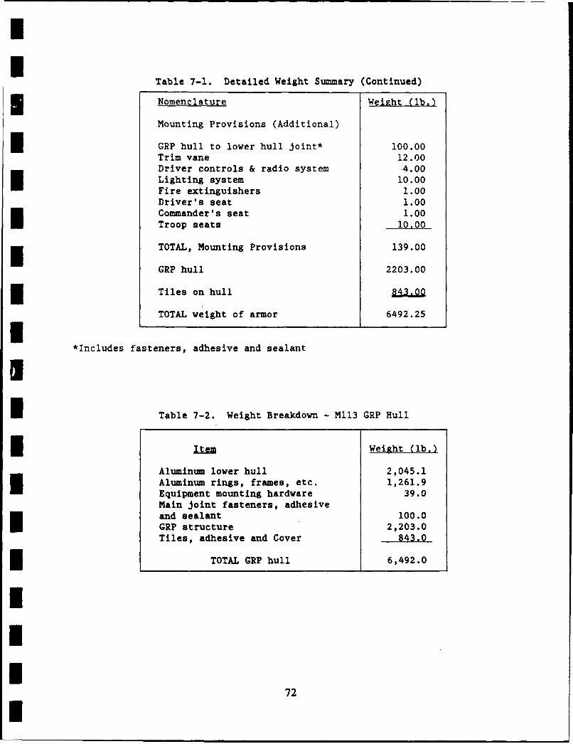
I
Table 7-1. Detailed Weight Summary (Continued)
Nomenclature Weight (lb.)
Mounting Provisions (Additional)
GRP hull to lower hull joint* 100.00Trim vane 12.00Driver controls & radio system -4.00Lighting system 10.00Fire extinguishers 1.00Driver's seat 1.00Commander's seat 1.00Troop seats 10.00
TOTAL, Mounting Provisions 139.00
GRP hull 2203.00
Tiles on hull 843.00
TOTAL weight of armor 6492.25I*Includes fasteners, adhesive and sealantI
I Table 7-2. Weight Breakdown - M113 GRP Hull
Item Weight (lb.)
Aluminum lower hull 2,045.1Aluminum rings, frames, etc. 1,261.9Equipment mounting hardware 39.0Main joint fasteners, adhesiveand sealant 100.0GRP structure 2,203.0Tiles, adhesive and Cover 843.0
l TOTAL GRP hull 6,492.0
III
72U
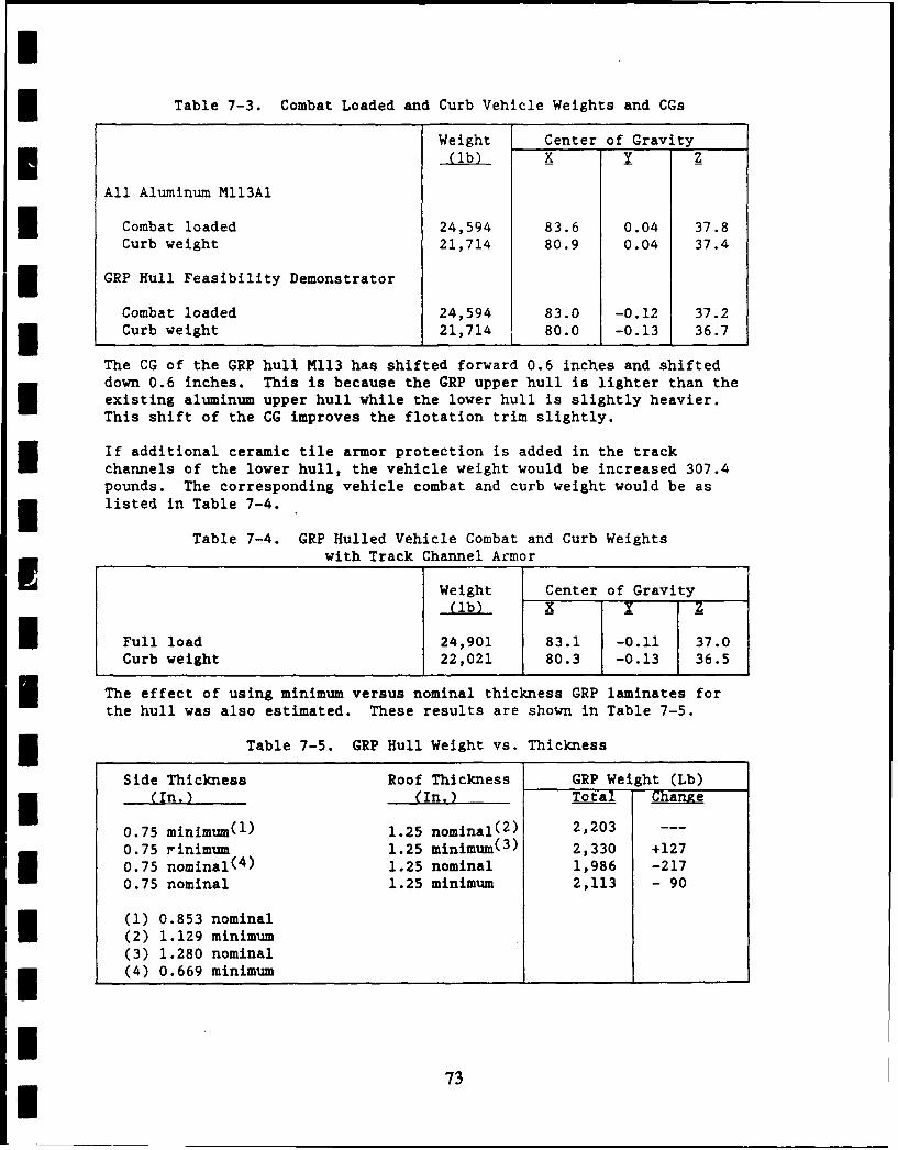
Iw
Table 7-3. Combat Loaded and Curb Vehicle Weights and CGs
Weight Center of Gravity_(lb) X Y Z
All Aluminum MII3Al
Combat loaded 24,594 83.6 0.04 37.8Curb weight 21,714 80.9 0.04 37.4
GRP Hull Feasibility Demonstrator
Combat loaded 24,594 83.0 -0.12 37.2Curb weight 21,714 80.0 -0.13 36.7
The CG of the GRP hull M113 has shifted forward 0.6 inches and shifteddown 0.6 inches. This is because the GRP upper hull is lighter than theexisting aluminum upper hull while the lower hull is slightly heavier.This shift of the CG improves the flotation trim slightly.
If additional ceramic tile armor protection is added in the trackchannels of the lower hull, the vehicle weight would be increased 307.4pounds. The corresponding vehicle combat and curb weight would be as
*listed in Table 7-4.
Table 7-4. GRP Hulled Vehicle Combat and Curb WeightsI with Track Channel Armor
Weight Center of Gravity
(lb) 1 X-
Full load 24,901 83.1 -0.11 37.0Curb weight 22,021 80.3 -0.13 36.5
The effect of using minimum versus nominal thickness GRP laminates forthe hull was also estimated. These results are shown in Table 7-5.
Table 7-5. GRP Hull Weight vs. Thickness
Side Thickness Roof Thickness GRP Weight (Lb)(In.) (In.) Total Change
0.75 minimum(1 ) 1.25 nominal( 2 ) 2,203 ---
0.75 rinimum 1.25 minimum(3 ) 2,330 +1270.75 nominal(4 ) 1.25 nominal 1,986 -2170.75 nominal 1.25 minimum 2,113 - 90
(1) 0.853 nominal(2) 1.129 minimum(3) 1.280 nominal(4) 0.669 minimum
I73I
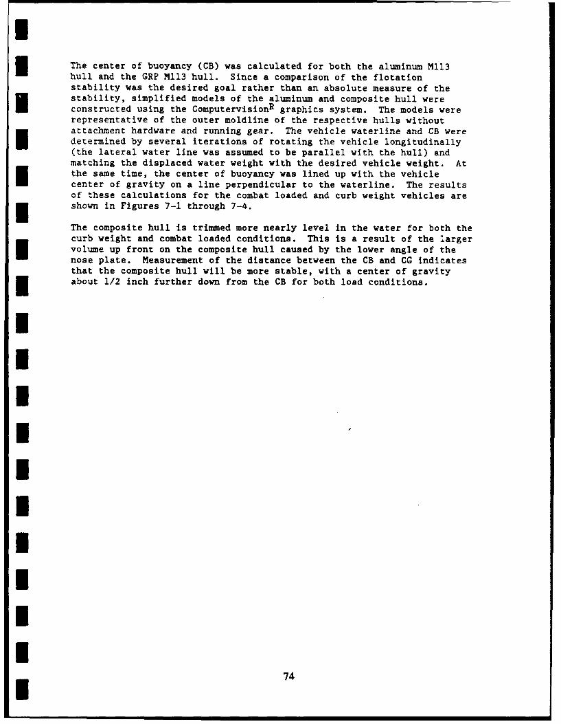
I
The center of buoyancy (CB) was calculated for both the aluminum M113hull and the GRP M113 hull. Since a comparison of the flotationstability was the desired goal rather than an absolute measure of thestability, simplified models of the aluminum and composite hull wereconstructed using the ComputervisionR graphics system. The models wererepresentative of the outer moldline of the respective hulls withoutattachment hardware and running gear. The vehicle waterline and CB weredetermined by several iterations of rotating the vehicle longitudinally(the lateral water line was assumed to be parallel with the hull) andmatching the displaced water weight with the desired vehicle weight. Atthe same time, the center of buoyancy was lined up with the vehiclecenter of gravity on a line perpendicular to the waterline. The resultsof these calculations for the combat loaded and curb weight vehicles areshown in Figures 7-1 through 7-4.
The composite hull is trimmed more nearly level in the water for both thecurb weight and combat loaded conditions. This is a result of the largervolume up front on the composite hull caused by the lower angle of thenose plate. Measurement of the distance between the CB and CG indicatesthat the composite hull will be more stable, with a center of gravityabout 1/2 inch further down from the CB for both load conditions.
IIIIIIIIIII74
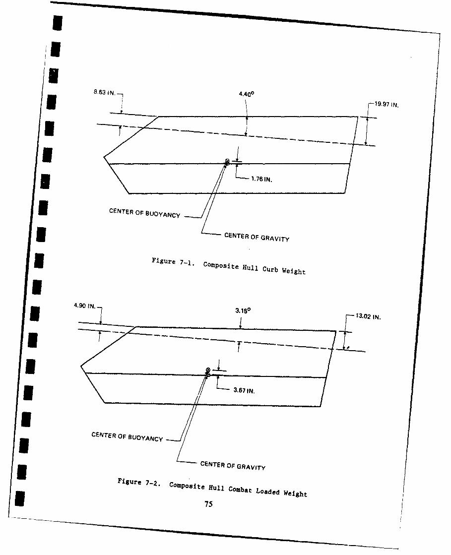
8.63 IN.- 4,400197IN
L1.76 IN.
3CENTER OF BUOYANCY
-
ICENTER OF GRAVITY
Figure 7-1. COMPOsite Hull Curb Weight
4.0IN 3.150
13.02 IN.
13671IN.
U CENTER OF BUOYANCY
IZ CENTER OF GRAVITY
Figure 7-2. Compo site Hfull Combat Loaded Weight*
75
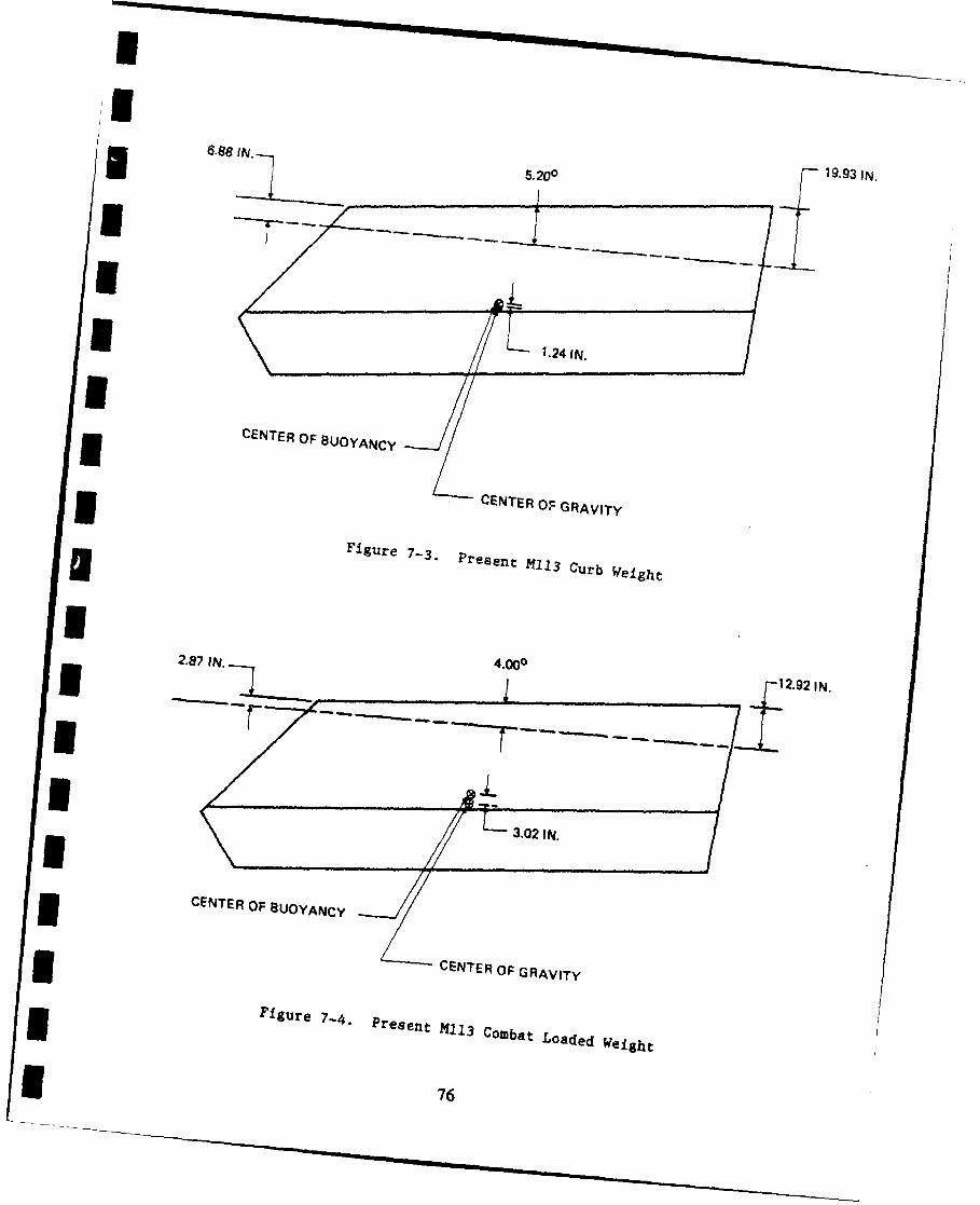
3. 008 1993IN
U l.24 IN./
I CENTER OF BUOYANCY
U CENTER OF GRAVITYIFigure
7- Present 1obtLoadeCur Weigh
I7
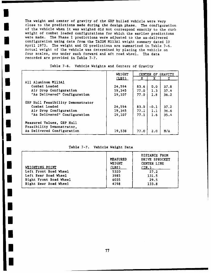
The weight and center of gravity of the GRP hulled vehicle were veryclose to the predictions made during the design phase. The configuration
I of the vehicle when it was weighed did not correspond exactly to the curbweight of combat loaded configurations for which the earlier predictionswere made. The Phase I predictions were adjusted to the as-deliveredconfiguration using data from the TACOM MII3Al weight summary dated 10April 1973. The weight and CG predictions are summarized in Table 7-6.Actual weight of the vehicle was determined by placing the vehicle onfour scales, one under each forward and aft road wheel. The datarecorded are provided in Table 7-7.
Il Table 7-6. Vehicle Weights and Centers of Gravity
WEIGHT CENTER OF GRAVITY(LBS) X X Z
Il All Aluminum M13AICombat Loaded 24,594 83.6 0.0 37.8Air Drop Configuration 19,345 77.0 1.3 37.4"As Delivered" Configuration 19,107 77.0 1.8 36.2
GRP Hull Feasibility DemonstratorCombat Loaded 24,594 83.0 -0.1 37.2Air Drop Configuration 19,345 77.1 1.1 36.6"As Delivered" Configuration 19,107 77.1 1.6 35.4
Measured Values, GRP HullFeasibility Demonstrator,As Delivered Configuration 19,538 77.0 2.0 N/AI
Table 7-7. Vehicle Weight Data
U DISTANCE FROM
MEASURED DRIVE SPROCKETWEIGHT CENTER LINE
WEIGHTING POINT (LBS) (IN.)Left Front Road Wheel 5320 27.2E Left Rear Road Wheel 3985 131.5Right Front Road Wheel 6035 29.5Right Rear Road Wheel 4198 133.8
II
I 77
I
8.0 MANFACTURING COST STUDY
The cost of manufacturing the GRP hull on a production basis wasestimated in the contract proposal, at the completion of che design(Phase I), and at the completion of fabrication (Phase II). Allestimates were in 1983 dollars. The estimated costs are summarized inTable 8-1. The basis of the estimates was for the production of 1,000hulls over a three year period. The Phase I and II estimates assumedfully automated production tooling for all metal working and welding.Manual layup of preimpregnated woven roving and hand laying of ceramictiles were assumed for the GRP fabrication. Manual production linemethods were assumed for assembly. The Phase I estimate was based on thepreliminary hull design. For the Phase II estimates, the Phase Iestimate was updated based on actual fabrication of the hull. Theestimate for the proposal was based on a conceptual design, and costswere estimated parametrically.
Labor and materials cost for the Phase I and II estimates are summarizedin Tables 8-2 and 8-3. The $39 per hour rate used for labor costs isthought to be typical of U.S. fabrication industries. Its derivation issummarized in Table 8-4. The materials costs are vendor estimates, and
* quantities of materials include trim losses.
The non-recurring cost in Table 8-1 include the cost of special purposetools and equipment dedicated to a hull production line and up frontproduction planning costs. It does not include general purpose machinetools or autoclaves. The non-recurring cost was based on costs developedduring a Martin Marietta proposal effort on the Army/Marine Corps Light3 Armored Vehicle (LAV) Program.
IIIII
UI 78
I
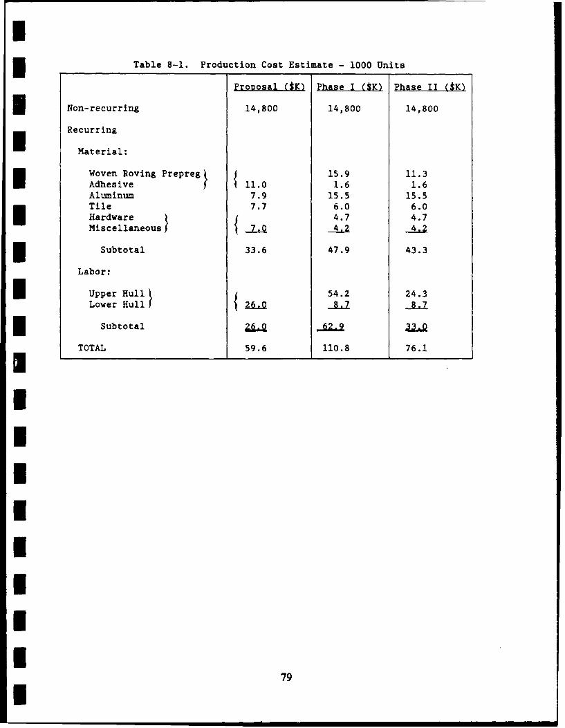
iTable 8-1. Production Cost Estimate - 1000 Units
Proposal ($K) Phase I ($K) Phase II ($K)
Non-recurring 14,800 14,800 14,800
Recurring
Material:
Woven Roving Prepreg 15.9 11.3Adhesive 11.0 1.6 1.6Aluminum 7.9 15.5 15.5Tile 7.7 6.0 6.0Hardware 4.7 4.7Miscellaneous 7.0 4.2 4.2
Subtotal 33.6 47.9 43.3
Labor:
Upper Hull , 54.2 24.3Lower Hull 26.0 8.7 8.7
Subtotal 26.0 62.9 33.0
TOTAL 59.6 110.8 76.1
IIIIIIIIi
79i
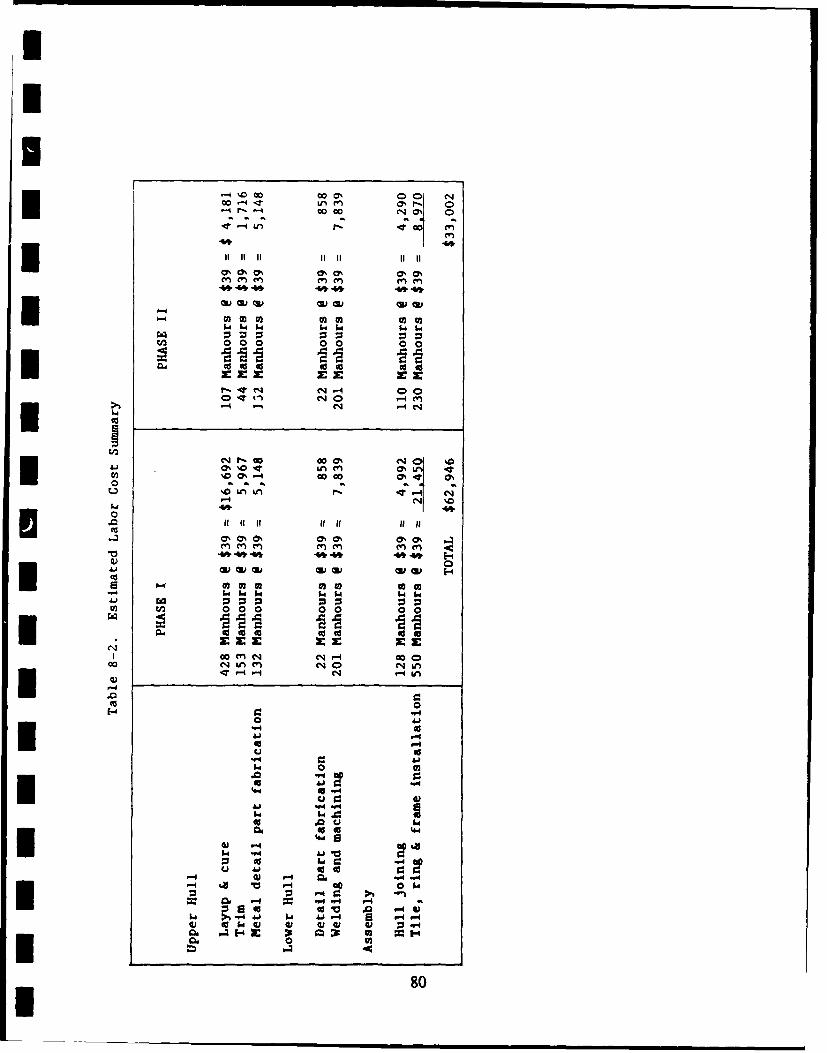
00en
0%%0 Ok 71C7
0 0 0 0 0 0 0
0 00
00 co4
401
CS0%0 &k O. 0%r-. 4-4 44k
w 64 64' 64 140 a a a a a
Go m444-4c
0 A
44444 444444
0
)I lz.00
08
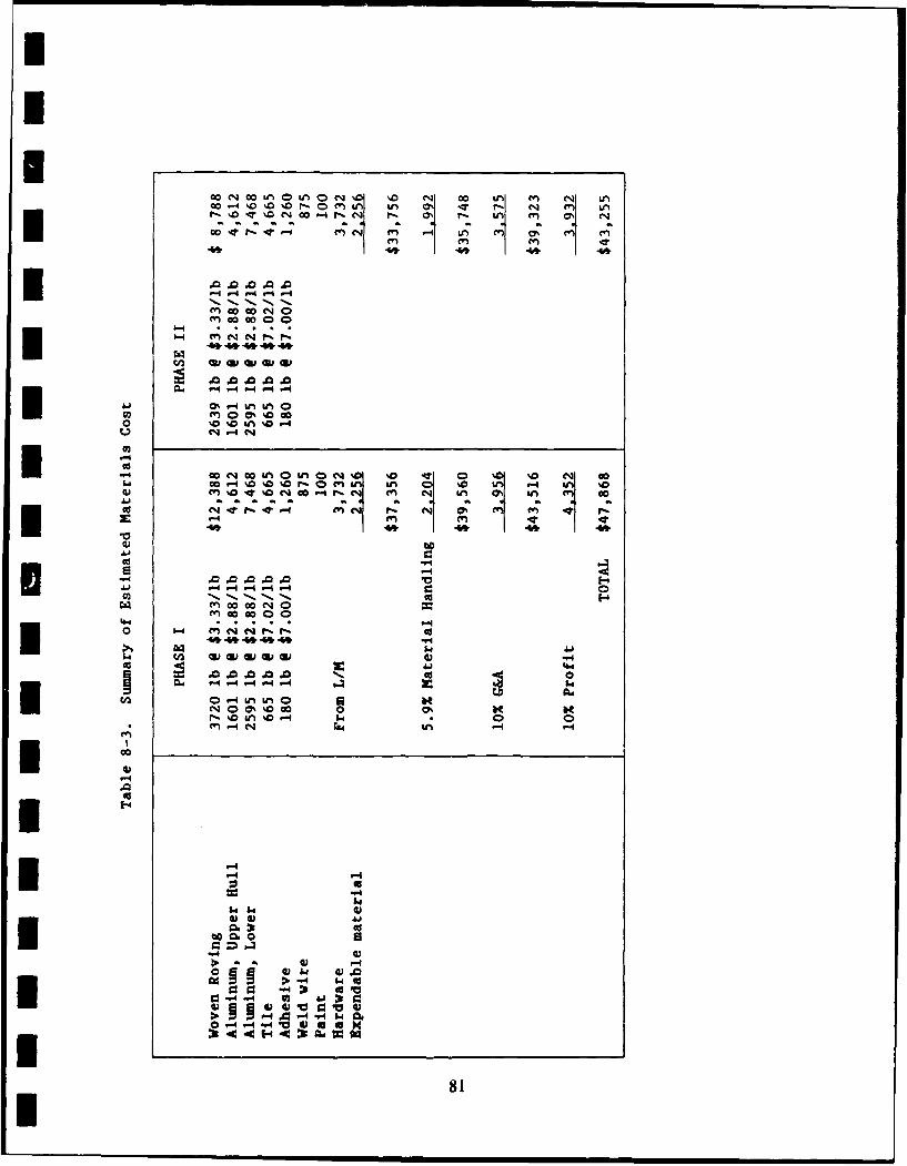
WI A0i q.o% 1 0L n LI4 Q% ,0ML u C%-Tr
I4 -- 4 -4-4
-4 0.-ift ft WU3 w(www*t%
4,A4,A4A4fAw 174V- -
0 At
ha % a%C %C2
I . .
44
9 '-4.0 .0 .0 .0 E"4 -4 .4r. r4
0,44,4 4 eq- r
I .0 .0 .0 .00
0O-4U~~ UnL taC3 00%%0 c 0 0'
-4 cm .4 .
-4
I I0 4 -4"- -
I8
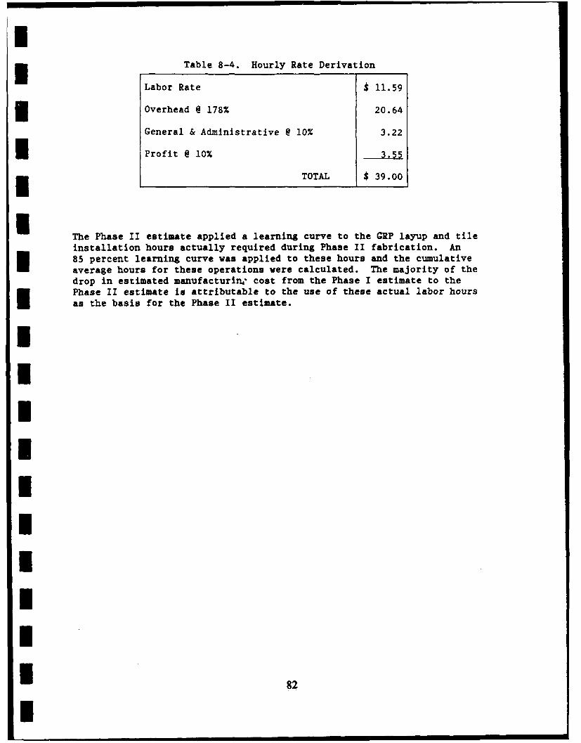
Table 8-4. Hourly Rate Derivation
Labor Rate $ 11.59
Overhead @ 178% 20.64
General & Administrative @ 10% 3.22
Profit @ 10% 3.5
TOTAL $ 39.00
The Phase II estimate applied a learning curve to the GRP layup and tileinstallation hours actually required during Phase II fabrication. An85 percent learning curve was applied to these hours and the cumulativeaverage hours for these operations were calculated. The majority of thedrop in estimated manufacturing cost from the Phase I estimate to thePhase II estimate is attributable to the use of these actual labor hoursas the basis for the Phase II estimate.
IIIUIIIIU
I 82 II
I9.0 TEST RESULTS
The vehicle was delivered to the Marine Corps at Camp Pendleton,California for field testing in October 1985. Prior to delivery, thevehicle was run for approximately 10 hours to demonstrate operability,immersed in water to verify its watertight integrity, and instrumentedwith strain gages at critical locations. Baseline static strains in thehull were measured with the vehicle supported on diagonally opposed roadwheels, and with a number one road wheel that bottomed against the top ofthe track channel.
I No problems were experienced with the vehicle during the 10 hours ofoperation. A small amount of leakage was observed around the ramp whenthe vehicle was immersed in water. This leakage was considered normal.The measured strains were very low, 0 to 100 micro inches, and consistentwith our prediction.
No problems related to the composite hull were observed during ona yearof field testing at Camp Pendleton. A detailed inspection of the hullwas conducted at Camp Pendleton in October 1986. At that time thevehicle had accumulated 159.8 hours (2330 miles) of operation. Theinspection revealed the following:
0 The polyurethane protective coating used on the right (engine)side of the vehicle showed several gouges in the track channeland a scuff mark of the vehicle side.
0 Some of the debonds between the cover sheet and tiles that hadbeen repaired (Section 8.6) prior to delivery had debonded again.
* Ultrasonic indications of porosity found during inspection ofthe bare hull (Section 6.2) could not be found under fieldconditions.
* Acid leaking from the battery box had locally removed paint fromthe GRP. There was no indication of damage to the laminate.
There were no indications of any degradation of the hull during the yearof field testing.
8IIII*I 83
10.0 RESEARCH AND DEVELOPMENT PLAN
Research and Development activities required to bring composite hulls tothe state of being production items are minimal. The large data baseavailable from the aircraft and marine industries will provide virtuallyall of the information needed to design and produce a composite hull.Items specifically related to a production composite hull that would berequired during a full scale development program are:
A complete specification of hull performance requirementsincluding loads, environmental, nuclear, and ballisticrequirements. Estimated cost $2 million
" Design of a vehicle hull to meet requirements. Estimated cost$1 million
* Qualification of materials, and design for the performancerequirements. Estimated cost $0.5 million
" Qualification of a prototype vehicle by field testing in allenvironments. Estimated cost $5 million
" Production engineering to assure a cost-effective, producibledesign. Estimated cost $1 million.
IIIIIIIII
84I
I
11.0 CONCLUSIONS AND RECOMMENDATIONS
On the basis of the Phase I and II efforts it has been concluded that:
I 1) The selected design is capable of withstanding all definedoperational loads without sustaining structural damage ordeflecting to a degree that would interfere with operation ofthe vehicle or its systems and equipment
2) The composite hull has not suffered any degradation in one yearof field testing by the Marine Corps
3) High quality woven roving/epoxy laminate having a 70 percentfiber content can be readily fabricated in the requiredthicknesses
4) The GRP/ceramic tile hull will provide greatly improvedballistic protection at a weight equal to that of the existingaluminum Ml13A1 hull
5) Design constraints required t6 make the GRP hull compatible withexisting Mll3Al hardware and aystems imposes a weight penalty onthe selected hull design.
It is recommended that:
1) A prototype composite hull for a high water speed armoredamphibious vehicle be fabricated and field tested
2) Critical features of the design be verified by structural
* element tests
3) Additional materials characterization tests be performed
4) The existing M113-based hull be subjected to more severe fieldenvironments (For example, tropical and arctic)
5) Field repair of ballistic damage be demonstrated.
IUIII
85I