Embed Size (px)
Citation preview

Composite Nonwoven Materials

The Textile Institute and Woodhead Publishing
The Textile Institute is a unique organisation in textiles, clothing and footwear. Incorporated in England by a Royal Charter granted in 1925, the Institute has individual and corporate members in over 90 countries. The aim of the Institute is to facilitate learning, recognise achievement, reward excellence and disseminate information within the global textiles, clothing and footwear industries.
Historically, The Textile Institute has published books of interest to its members and the textile industry. To maintain this policy, the Institute has entered into partnership with Woodhead Publishing Limited to ensure that Institute members and the textile industry continue to have access to high calibre titles on textile science and technology.
Most Woodhead titles on textiles are now published in collaboration with The Textile Institute. Through this arrangement, the Institute provides an Editorial Board which advises Woodhead on appropriate titles for future publication and suggests possible editors and authors for these books. Each book published under this arrangement carries the Institute’s logo.
Woodhead books published in collaboration with The Textile Institute are offered to Textile Institute members at a substantial discount. These books, together with those published by The Textile Institute that are still in print, are offered on the Elsevier website at: http://store.elsevier.com/ . Textile Institute books still in print are also available directly from the Institute’s web site at: www.textileinstitutebooks.com .
A list of Woodhead books on textiles science and technology, most of which have been published in collaboration with The Textile Institute, can be found towards the end of the contents pages.
Woodhead Publishing Series in Textiles: Number 155
Composite Nonwoven Materials
Structure, Properties and Applications
Edited by Dipayan Das and Behnam Pourdeyhimi
amsterdam • boston • cambridge • heidelberg • londonnew york • oxford • paris • san diego
san francisco • singapore • sydney • tokyoWoodhead Publishing is an imprint of Elsevier

Woodhead Publishing is an imprint of Elsevier 80 High Street, Sawston, Cambridge, CB22 3HJ, UK 225 Wyman Street, Waltham, MA 02451, USA Langford Lane, Kidlington, OX5 1GB, UK
Copyright © 2014 Woodhead Publishing Limited. All rights reserved
No part of this publication may be reproduced, stored in a retrieval system or transmitted in any form or by any means electronic, mechanical, photocopying, recording or otherwise without the prior written permission of the publisher. Permissions may be sought directly from Elsevier’s Science & Technology Rights Department in Oxford, UK: phone (+44) (0) 1865 843830; fax (+44) (0) 1865 853333; email: [email protected]. Alternatively, you can submit your request online by visiting the Elsevier website at http://elsevier.com/locate/permissions, and selecting Obtaining permission to use Elsevier material.
Notice No responsibility is assumed by the publisher for any injury and/or damage to persons or property as a matter of products liability, negligence or otherwise, or from any use or operation of any methods, products, instructions or ideas contained in the material herein. Because of rapid advances in the medical sciences, in particular, independent verifi cation of diagnoses and drug dosages should be made.
British Library Cataloguing-in-Publication Data A catalogue record for this book is available from the British Library .
Library of Congress Control Number: 2013956119
ISBN 978-0-85709-770-5 (print) ISBN 978-0-85709-775-0 (online)
For information on all Woodhead Publishing publicationsvisit our website at http://store.elsevier.com
Typeset by Refi neCatch Limited, Bungay, Suffolk
Printed and bound in the United Kingdom
v
Contributor contact details ix Woodhead Publishing Series in Textiles xi
1 Introduction to composite nonwovens 1 D. DAS, Indian Institute of Technology Delhi, India
1.1 Introduction 1 1.2 Classifi cation of composite nonwovens 5 1.3 Processing, markets and applications 13 1.4 Conclusion and future trends 15 1.5 Sources of further information and advice 16 1.6 References 16
2 Natural and synthetic fi bres for composite nonwovens 20 S. MUKHOPADHYAY, Indian Institute of Technology Delhi, India
2.1 Introduction 20 2.2 Natural and biodegradable fi bres for nonwovens 20 2.3 Polypropylene and polyester fi bres 22 2.4 Polyethylene and nylon fi bres 23 2.5 Bicomponent fi bres 24 2.6 References 28
3 Structure of composite nonwovens 30 D. DAS, Indian Institute of Technology Delhi, India and B. NECKÁŘ, Technical University of Liberec, Czech Republic
3.1 Introduction 30 3.2 Fibre characteristics in composite nonwovens 30 3.3 Fibre packing in composite nonwovens 41 3.4 Fibre orientation in composite nonwovens 44 3.5 Pore characteristics in composite nonwovens 52 3.6 Conclusion 56
Contents
vi Contents
3.7 Sources of further information and advice 56 3.8 References 57
4 Properties of composite nonwovens 58 D. DAS, Indian Institute of Technology Delhi, India
4.1 Introduction 58 4.2 Mechanical properties of composite nonwovens 58 4.3 Fluid permeability of composite nonwovens 60 4.4 Thermal properties of composite nonwovens 64 4.5 Liquid sorption characteristics of composite nonwovens 65 4.6 Particle fi ltration behaviour of composite nonwovens 66 4.7 Conclusion 71 4.8 Sources of further information and advice 71 4.9 References 71
5 Composite nonwovens in absorbent hygiene products 74 D. DAS, Indian Institute of Technology Delhi, India
5.1 Introduction 74 5.2 Key material requirements 75 5.3 Baby diapers 76 5.4 Feminine sanitary pads 81 5.5 Adult incontinence pads 84 5.6 Conclusion and future trends 86 5.7 Sources of further information and advice 87 5.8 References 87
6 Composite nonwovens in wipes 89 R. S. RENGASAMY, Indian Institute of Technology Delhi, India
6.1 Introduction 89 6.2 Materials in wipes 90 6.3 Wet wipes 91 6.4 Web forming technologies for wipes 92 6.5 Web bonding processes for wipes 95 6.6 Surface texturing of wipes 96 6.7 Composite nonwoven wipes 97 6.8 Multi- fi bre composite nonwoven wipes 98 6.9 Multilayer composite latex bonded nonwoven wipes 100 6.10 Hydroentangled (spunlaced) multilayer composite
nonwoven wipes 100 6.11 Thermobonded multilayer composite nonwoven
wipes 109 6.12 Needlepunched composite nonwoven wipes 112 6.13 Other multilayer nonwoven wipes 113
Contents vii
6.14 Conclusion and future trends 113 6.15 References 118
7 Composite nonwovens in fi lters: theory 120 A. MUKHOPADHYAY, National Institute of Technology Jalandhar, India
7.1 Introduction 120 7.2 Mechanisms of fi ltration: general 125 7.3 Mechanisms of fi ltration: particle capture entrapment 126 7.4 Adsorption 140 7.5 Absorption 141 7.6 Coalescing 141 7.7 Media for gel removal 144 7.8 Mechanisms of fi ltration: electro- fi ltration 146 7.9 Separation by antimicrobial media 147 7.10 Extraction 147 7.11 Key requirements for fi ltration media 147 7.12 Characteristics of nonwoven fi lters 151 7.13 Types of nonwoven fi lter 152 7.14 Conclusion 160 7.15 References 161
8 Composite nonwovens in fi lters: applications 164 A. MUKHOPADHYAY, National Institute of Technology Jalandhar, India
8.1 Introduction 164 8.2 The role of composite nonwovens in fi lters: combining
mechanical support and durability with fi ltration 166 8.3 The role of composite nonwovens in fi lters: providing two
or more layers of different fi ltration effi ciency 181 8.4 The role of composite nonwovens in fi lters: combining
different separation technologies/functionality into one fi lter medium 182
8.5 Applications of composite nonwovens 190 8.6 Applications in air/gas fi ltration 192 8.7 Applications in liquid fi ltration 198 8.8 Applications in engine fi ltration 200 8.9 Conclusion 204 8.10 References 204
9 Composite nonwovens in medical applications 211 S. GHOSH, Indian Institute of Technology Delhi, India
9.1 Introduction 211 9.2 Surgical gowns 212 9.3 Surgical facemasks and other clinical wearable products 213 9.4 Wipes 214

viii Contents
9.5 Wound dressings, pads and swabs 214 9.6 Scaffolds for tissue engineering 216 9.7 Hernia meshes 218 9.8 Filtration materials for medical applications 219 9.9 Incontinence products 220 9.10 Conclusion and future trends 220 9.11 References 220 9.12 Appendix: recent patents based on composite nonwovens
for medical applications 223
Index 225
ix
Contributor contact details
Editors D. Das Department of Textile Technology Indian Institute of Technology Delhi Hauz Khas New Delhi 110016, India
E-mail: [email protected]
B. Pourdeyhimi North Carolina State University 2200 Hillsborough Raleigh, NC 27695, USA
E-mail: [email protected]
Chapter 1
D. Das Department of Textile Technology Indian Institute of Technology
Delhi Hauz Khas New Delhi 110016, India
E-mail: [email protected]
Chapter 2
S. Mukhopadhyay Department of Textile Technology Indian Institute of Technology
Delhi Hauz Khas New Delhi 110016, India
E-mail: [email protected]
Chapter 3
D. Das* Department of Textile Technology Indian Institute of Technology Delhi Hauz Khas New Delhi 110016, India
E-mail: [email protected]
B. Neckář Department of Textile Technology Faculty of Textiles Technical University of Liberec Studentská 2, 461 17 Liberec 1 Czech Republic
E-mail: [email protected]
(* = main contact)

x Contributor contact details
Chapter 4
D. Das Department of Textile Technology Indian Institute of Technology Delhi Hauz Khas New Delhi 110016, India
E-mail: [email protected]
Chapter 5
D. Das Department of Textile Technology Indian Institute of Technology Delhi Hauz Khas New Delhi 110016, India
E-mail: [email protected]
Chapter 6
R. S. Rengasamy Department of Textile Technology Indian Institute of Technology Delhi Hauz Khas New Delhi 110016, India
E-mail: [email protected]
Chapter 7
A. Mukhopadhyay Department of Textile Technology National Institute of Technology
Jalandhar Jalandhar 144011, India
E-mail: [email protected]
Chapter 8
A. Mukhopadhyay Department of Textile Technology National Institute of Technology
Jalandhar Jalandhar 144011, India
E-mail: [email protected]
Chapter 9
S. Ghosh Department of Textile Technology Indian Institute of Technology Delhi Hauz Khas New Delhi 110016, India
E-mail: [email protected]
xi
1 Watson’s textile design and colour Seventh edition Edited by Z. Grosicki
2 Watson’s advanced textile design Edited by Z. Grosicki
3 Weaving Second edition P. R. Lord and M. H. Mohamed
4 Handbook of textile fi bres Volume 1: Natural fi bres J. Gordon Cook
5 Handbook of textile fi bres Volume 2: Man- made fi bres J. Gordon Cook
6 Recycling textile and plastic waste Edited by A. R. Horrocks
7 New fi bres Second edition T. Hongu and G. O. Phillips
8 Atlas of fi bre fracture and damage to textiles Second edition J. W. S. Hearle, B. Lomas and W. D. Cooke
9 Ecotextile ’98 Edited by A. R. Horrocks
10 Physical testing of textiles B. P. Saville
11 Geometric symmetry in patterns and tilings C. E. Horne
12 Handbook of technical textiles Edited by A. R. Horrocks and S. C. Anand
13 Textiles in automotive engineering W. Fung and J. M. Hardcastle
14 Handbook of textile design J. Wilson
15 High- performance fi bres Edited by J. W. S. Hearle
16 Knitting technology Third edition D. J. Spencer
17 Medical textiles Edited by S. C. Anand
18 Regenerated cellulose fi bres Edited by C. Woodings
19 Silk, mohair, cashmere and other luxury fi bres Edited by R. R. Franck
Woodhead Publishing Series in Textiles

xii Woodhead Publishing Series in Textiles
20 Smart fi bres, fabrics and clothing Edited by X. M. Tao
21 Yarn texturing technology J. W. S. Hearle, L. Hollick and D. K. Wilson
22 Encyclopedia of textile fi nishing H-K. Rouette
23 Coated and laminated textiles W. Fung
24 Fancy yarns R. H. Gong and R. M. Wright
25 Wool: Science and technology Edited by W. S. Simpson and G. Crawshaw
26 Dictionary of textile fi nishing H-K. Rouette
27 Environmental impact of textiles K. Slater
28 Handbook of yarn production P. R. Lord
29 Textile processing with enzymes Edited by A. Cavaco-Paulo and G. Gübitz
30 The China and Hong Kong denim industry Y. Li, L. Yao and K. W. Yeung
31 The World Trade Organization and international denim trading Y. Li, Y. Shen, L. Yao and E. Newton
32 Chemical fi nishing of textiles W. D. Schindler and P. J. Hauser
33 Clothing appearance and fi t J. Fan, W. Yu and L. Hunter
34 Handbook of fi bre rope technology H. A. McKenna, J. W. S. Hearle and N. O’Hear
35 Structure and mechanics of woven fabrics J. Hu
36 Synthetic fi bres: nylon, polyester, acrylic, polyolefi n Edited by J. E. McIntyre
37 Woollen and worsted woven fabric design E. G. Gilligan
38 Analytical electrochemistry in textiles P. Westbroek, G. Priniotakis and P. Kiekens
39 Bast and other plant fi bres R. R. Franck
40 Chemical testing of textiles Edited by Q. Fan
41 Design and manufacture of textile composites Edited by A. C. Long
42 Effect of mechanical and physical properties on fabric hand Edited by H. M. Behery
43 New millennium fi bres T. Hongu, M. Takigami and G. O. Phillips
Woodhead Publishing Series in Textiles xiii
44 Textiles for protection Edited by R. A. Scott
45 Textiles in sport Edited by R. Shishoo
46 Wearable electronics and photonics Edited by X. M. Tao
47 Biodegradable and sustainable fi bres Edited by R. S. Blackburn
48 Medical textiles and biomaterials for healthcare Edited by S. C. Anand, M. Miraftab, S. Rajendran and J. F. Kennedy
49 Total colour management in textiles Edited by J. Xin
50 Recycling in textiles Edited by Y. Wang
51 Clothing biosensory engineering Y. Li and A. S. W. Wong
52 Biomechanical engineering of textiles and clothing Edited by Y. Li and D. X-Q. Dai
53 Digital printing of textiles Edited by H. Ujiie
54 Intelligent textiles and clothing Edited by H. R. Mattila
55 Innovation and technology of women’s intimate apparel W. Yu, J. Fan, S. C. Harlock and S. P. Ng
56 Thermal and moisture transport in fi brous materials Edited by N. Pan and P. Gibson
57 Geosynthetics in civil engineering Edited by R. W. Sarsby
58 Handbook of nonwovens Edited by S. Russell
59 Cotton: Science and technology Edited by S. Gordon and Y-L. Hsieh
60 Ecotextiles Edited by M. Miraftab and A. R. Horrocks
61 Composite forming technologies Edited by A. C. Long
62 Plasma technology for textiles Edited by R. Shishoo
63 Smart textiles for medicine and healthcare Edited by L. Van Langenhove
64 Sizing in clothing Edited by S. Ashdown
65 Shape memory polymers and textiles J. Hu
66 Environmental aspects of textile dyeing Edited by R. Christie
67 Nanofi bers and nanotechnology in textiles Edited by P. Brown and K. Stevens
xiv Woodhead Publishing Series in Textiles
68 Physical properties of textile fi bres Fourth edition W. E. Morton and J. W. S. Hearle
69 Advances in apparel production Edited by C. Fairhurst
70 Advances in fi re retardant materials Edited by A. R. Horrocks and D. Price
71 Polyesters and polyamides Edited by B. L. Deopura, R. Alagirusamy, M. Joshi and B. S. Gupta
72 Advances in wool technology Edited by N. A. G. Johnson and I. Russell
73 Military textiles Edited by E. Wilusz
74 3D fi brous assemblies: Properties, applications and modelling of three- dimensional textile structures J. Hu
75 Medical and healthcare textiles Edited by S. C. Anand, J. F. Kennedy, M. Miraftab and S. Rajendran
76 Fabric testing Edited by J. Hu
77 Biologically inspired textiles Edited by A. Abbott and M. Ellison
78 Friction in textile materials Edited by B. S. Gupta
79 Textile advances in the automotive industry Edited by R. Shishoo
80 Structure and mechanics of textile fi bre assemblies Edited by P. Schwartz
81 Engineering textiles: Integrating the design and manufacture of textile products Edited by Y. E. El-Mogahzy
82 Polyolefi n fi bres: Industrial and medical applications Edited by S. C. O. Ugbolue
83 Smart clothes and wearable technology Edited by J. McCann and D. Bryson
84 Identifi cation of textile fi bres Edited by M. Houck
85 Advanced textiles for wound care Edited by S. Rajendran
86 Fatigue failure of textile fi bres Edited by M. Miraftab
87 Advances in carpet technology Edited by K. Goswami
88 Handbook of textile fi bre structure Volume 1 and Volume 2 Edited by S. J. Eichhorn, J. W. S. Hearle, M. Jaffe and T. Kikutani
89 Advances in knitting technology Edited by K-F. Au
90 Smart textile coatings and laminates Edited by W. C. Smith

Woodhead Publishing Series in Textiles xv
91 Handbook of tensile properties of textile and technical fi bres Edited by A. R. Bunsell
92 Interior textiles: Design and developments Edited by T. Rowe
93 Textiles for cold weather apparel Edited by J. T. Williams
94 Modelling and predicting textile behaviour Edited by X. Chen
95 Textiles, polymers and composites for buildings Edited by G. Pohl
96 Engineering apparel fabrics and garments J. Fan and L. Hunter
97 Surface modifi cation of textiles Edited by Q. Wei
98 Sustainable textiles Edited by R. S. Blackburn
99 Advances in yarn spinning technology Edited by C. A. Lawrence
100 Handbook of medical textiles Edited by V. T. Bartels
101 Technical textile yarns Edited by R. Alagirusamy and A. Das
102 Applications of nonwovens in technical textiles Edited by R. A. Chapman
103 Colour measurement: Principles, advances and industrial applications Edited by M. L. Gulrajani
104 Fibrous and composite materials for civil engineering applications Edited by R. Fangueiro
105 New product development in textiles: Innovation and production Edited by L.Horne
106 Improving comfort in clothing Edited by G. Song
107 Advances in textile biotechnology Edited by V. A. Nierstrasz and A. Cavaco-Paulo
108 Textiles for hygiene and infection control Edited by B. McCarthy
109 Nanofunctional textiles Edited by Y. Li
110 Joining textiles: Principles and applications Edited by I. Jones and G. Stylios
111 Soft computing in textile engineering Edited by A. Majumdar
112 Textile design Edited by A. Briggs-Goode and K. Townsend
113 Biotextiles as medical implants Edited by M. W. King, B. S. Gupta and R. Guidoin
114 Textile thermal bioengineering Edited by Y. Li

xvi Woodhead Publishing Series in Textiles
115 Woven textile structure B. K. Behera and P. K. Hari
116 Handbook of textile and industrial dyeing. Volume 1: Principles, processes and types of dyes Edited by M. Clark
117 Handbook of textile and industrial dyeing. Volume 2: Applications of dyes Edited by M. Clark
118 Handbook of natural fi bres. Volume 1: Types, properties and factors affecting breeding and cultivation Edited by R. Kozłowski
119 Handbook of natural fi bres. Volume 2: Processing and applications Edited by R. Kozłowski
120 Functional textiles for improved performance, protection and health Edited by N. Pan and G. Sun
121 Computer technology for textiles and apparel Edited by J. Hu
122 Advances in military textiles and personal equipment Edited by E. Sparks
123 Specialist yarn and fabric structures Edited by R. H. Gong
124 Handbook of sustainable textile production M. I. Tobler-Rohr
125 Woven textiles: Principles, developments and applications Edited by K. Gandhi
126 Textiles and fashion: Materials design and technology Edited by R. Sinclair
127 Industrial cutting of textile materials I. Viļumsone-Nemes
128 Colour design: Theories and applications Edited by J. Best
129 False twist textured yarns C. Atkinson
130 Modelling, simulation and control of the dyeing process R. Shamey and X. Zhao
131 Process control in textile manufacturing Edited by A. Majumdar, A. Das, R. Alagirusamy and V. K. Kothari
132 Understanding and improving the durability of textiles Edited by P. A. Annis
133 Smart textiles for protection Edited by R. A. Chapman
134 Functional nanofi bers and applications Edited by Q. Wei
135 The global textile and clothing industry: Technological advances and future challenges Edited by R. Shishoo
136 Simulation in textile technology: Theory and applications Edited by D. Veit
Woodhead Publishing Series in Textiles xvii
137 Pattern cutting for clothing using CAD: How to use Lectra Modaris pattern cutting software M. Stott
138 Advances in the dyeing and fi nishing of technical textiles M. L. Gulrajani
139 Multidisciplinary know- how for smart textiles developers Edited by T. Kirstein
140 Handbook of fi re resistant textiles Edited by F. Selcen Kilinc
141 Handbook of footwear design and manufacture Edited by A. Luximon
142 Textile- led design for the active ageing population Edited by J. McCann and D. Bryson
143 Optimizing decision making in the apparel supply chain using artifi cial intelligence (AI): From production to retail Edited by W. K. Wong, Z. X. Guo and S. Y. S. Leung
144 Mechanisms of fl at weaving technology V. V. Choogin, P. Bandara and E. V. Chepelyuk
145 Innovative jacquard textile design using digital technologies F. Ng and J. Zhou
146 Advances in shape memory polymers J. Hu
147 Design of clothing manufacturing processes: A systematic approach to planning, scheduling and control J. Gersak
148 Anthropometry, apparel sizing and design D. Gupta and N. Zakaria
149 Silk: Processing, properties and applications Edited by K. Murugesh Babu
150 Advances in fi lament yarn spinning of textiles and polymers Edited by D. Zhang
151 Designing apparel for consumers: The impact of body shape and size Edited by M.-E. Faust and S. Carrier
152 Fashion supply chain management using radio frequency identifi cation (RFID) technologies Edited by W. K. Wong and Z. X. Guo
153 High performance textiles and their applications Edited by C. Lawrence
154 Protective clothing: Managing thermal stress Edited by F. Wang and C. Gao
155 Composite nonwoven materials Edited by D. Das and B. Pourdeyhimi
156 Functional fi nishes for textiles Edited by R. Paul
157 Assessing the environmental impact of textiles and the clothing supply chain S. S. Muthu

xviii Woodhead Publishing Series in Textiles
158 Braiding technology for textiles Y. Kyosev
159 Principles of colour appearance and measurement A. K. R. Choudhury
1
© 2014 Woodhead Publishing Limited
1 Introduction to composite nonwovens
D. DAS, Indian Institute of Technology Delhi, India
DOI: 10.1533/9780857097750.1
Abstract: This chapter gives an introduction to composite nonwovens. It begins with the defi nitions of composites and nonwovens and continues to discuss how these defi nitions are used to defi ne composite nonwovens. It then classifi es composite nonwovens according to the materials used or manufacturing processes employed for the creation of composite nonwovens. Each class of composite nonwoven is described and discussed with numerous practical examples. The chapter then proceeds to discuss the scope, markets and applications of composite nonwovens. The fi nal section highlights the challenges and promises of composite nonwovens.
Key words: composite, nonwoven, defi nition, classifi cation, scope, market, application.
1.1 Introduction
The term ‘composite nonwoven’ has an interesting etymology. Impressionis-tically, it appears to mean a category of nonwoven materials which is prepared by a combination of different nonwoven preforms or different nonwoven fabrics. In the past, the members of the nonwoven industry used the terms ‘composite nonwoven’ and ‘nonwoven composite’ sometimes synonymously and sometimes differently. Those who preferred to use them differently would mean composite nonwoven as a material combining nonwoven preforms or nonwoven fabrics with at least one other material such as yarn, cloth, knit, braid and fi lm, and nonwoven composite as a material consisting of a resinous matrix reinforced by an embedded nonwoven fabric (Das et al. , 2012). Though composite nonwovens prepared by various combinations of materials and processes are well established, the defi nition of composite nonwovens has been a topic of debate in the nonwoven and allied industries. In the following sections, the defi nitions of the term ‘composite’ and ‘nonwoven’ are given and how they are used to defi ne the term ‘composite nonwovens’ is discussed.
1.1.1 Defi nitions of composite
The term ‘composite’ comes from the Latin word compositus , which means ‘put together’ indicating something made by putting together different parts or materials. Nevertheless, the defi nition of the term ‘composite’ has been continued to be confusing to the members of the nonwoven and allied industries.
2 Composite Nonwoven Materials
Holliday (1990) suggested a defi nition of composite for the nonwoven industry as a material comprising two or more different parts or elements in which each material has its own unique characteristics. These materials may include fi bre, fabric, plastics, superabsorbents or other materials that effect and become a homogeneous part of, and are nonseparable from, the total structure.
Holliday made an attempt to differentiate composites from laminates by stating that a laminate is a material which is formed by uniting or bonding two or more distant layers that may be similar or different in composition, with heat, adhesive or pressure. These layers may include fabrics, foam, sheets, webs or fi lms such that each layer retains a substantial portion of its original characteristics and therefore does not become homogeneous in the structure. Further, a laminate can be theoretically delaminated, i.e. the layers can be separated from one another.
The North American Association of the Nonwoven Fabrics Industry (INDA) and the European Disposables and Nonwovens Association (EDANA) (2005) jointly defi ne a composite material as a macroscopic combination of two or more distinct materials, having a recognizable interface between them. This defi nition of composite has not been accepted by the allied industries, however. The textile industry, which is closely associated with the nonwoven industry, follows another defi nition of composite. As per the Textile Institute Textile Terms and Defi nitions, composite is defi ned as a product formed by intimately combining two or more discrete physical phases, usually a solid matrix and a fi brous material (McIntyre and Daniels, 1995). The textile industry therefore thinks of composites as fi bre- reinforced-composites only.
The man- made fi bre industry, which is closely associated with the nonwoven industry, follows a similar defi nition of composite. As per the dictionary of man- made fi bres, composites are materials with plastics as matrix and high tenacity fi bres or short fi bres as reinforcement; without this reinforcement, plastics would be insuffi ciently rigid, solid and impact resistant (Koslowski, 1998). Thus the man- made fi bre industry thinks about composites as fi bre- reinforced and plastic- matrix composites only. The polymer industry however typically follows another defi nition of composite. The Encyclopaedia of Polymer Science and Technology (Mark, 1970) defi nes composites as combinations of materials differing in composition or form on a macroscopic scale in which all of the constituents in the composites retain their identities and do not dissolve or otherwise completely merge into each other.
The composite industry uses a different defi nition of composite. As per the ASTM (Committee D-30 on Composite Materials) standard D3878–07, a composite material is defi ned as a substance consisting of two or more materials, insoluble in one another, which are combined to form a useful engineering material possessing certain properties not possessed by the constituents. Further, a composite material is inherently inhomogeneous on a microscopic scale, but can often be assumed to be homogeneous on a macroscopic scale for certain engineering applications. The constituents of a composite retain their identities:
Introduction to composite nonwovens 3
they do not dissolve or otherwise merge completely into each other, although they act in concert.
Each industry thus follows its own defi nition of composites. It appears that each of these industries have different circumstances and motivations so it is no wonder that they have pushed their own criteria for defi ning composites.
1.1.2 Defi nitions of nonwoven
The defi nition of nonwoven has had an interesting history. A chronological description of the defi nitions of nonwoven has been given by Batra and Pourdeyhimi (2012). It can be observed that nonwoven has been defi ned differently from time to time by different authors, standardization agencies and industry associations. Nevertheless, the following defi nitions of nonwoven are generally found acceptable worldwide. As per ISO 9092, nonwoven is defi ned as:
a manufactured sheet, web or batt of directionally or randomly oriented fi bres, bonded by friction, and/or cohesion and/or adhesion, excluding paper and products which are woven, knitted, tufted, stitch- bonded incorporating binding yarns or fi laments or felted by wet- milling, whether or not additionally needled. The fi bres may be of natural or man- made origin. They may be staple or continuous fi laments or be formed in situ. Note that the wet- laid nonwovens are distinguished from the wet- laid papers by a clause that a material shall be regarded as a nonwoven if more than 50% by mass of its fi brous content is made up of fi bres (excluding chemically digested vegetable fi bres) with a length to diameter ratio greater than 300; else if more than 30% by mass of its fi brous content is made up of fi bres (excluding chemically digested vegetable fi bres) with a length to diameter ratio greater than 300 and its density is less than 0.40 g/cm 3 .
This defi nition of nonwoven by ISO 9092 has been adapted by CEN (EN 29092) and consequently by DIN, AFNOR, and all standardization offi ces in the EU.
ASTM prefers to defi ne nonwoven as ‘a textile structure produced by bonding or interlocking of fi bres, or both, accomplished by mechanical, chemical, thermal, or solvent means, and combinations thereof. Note that the term does not include paper, or fabrics which are woven, knitted, tufted, or those made by wool or other felting processes.’ This defi nition is available in many ASTM standards including D 123, D 1117, D 2646, D 3786, D 3787, D 5684, D 5732, D 5733, D 5734, D 5735, and D 5736.
There are currently two leading associations of nonwovens producers in the world, namely EDANA (the European Disposables and Nonwovens Association) and INDA (the North American Association of the Nonwoven Fabrics Industry). They have been the voice of the nonwoven industries in Europe and North America, respectively. Nonwovens are defi ned by them as well. Though EDANA has adopted the defi nition of nonwoven given by ISO 9092 or CEN 29092, INDA
4 Composite Nonwoven Materials
prefers to defi ne nonwovens in another way. According to INDA, ‘nonwoven fabrics are broadly defi ned as sheet or web structures bonded together by entangling fi bre or fi laments (and by perforating fi lms) mechanically, thermally or chemically. They are fl at and porous sheets that are made directly from separate fi bres or from molten plastic or plastic fi lm. They are not made by weaving or knitting and do not require converting the fi bres to yarn.’ It is quite interesting to note that everybody has their own defi nition of nonwoven and there is no unique defi nition of nonwovens existing in the world.
1.1.3 Defi nitions of composite nonwoven
There are also defi nitions available for composite nonwovens. Bikales (1976) classifi ed nonwoven fabrics into four categories:
1 fabrics produced by chemical and mechanical fi nish 2 fabrics produced by wet processes using modifi ed papermaking techniques 3 spunbonded fabrics 4 composite fabrics produced from laminates of scrims, fi bres, or foams with
tissue, fi lms, or other nonwoven fabrics.
An example of the fourth category of nonwoven fabric is as follows. Continuous- fi lament yarns were coated with a phenolic resin and converted into a cross- laid nonwoven scrim to which layers of tissue were applied to each side and fi nally the composite was exposed to heat to allow the adhesive to set. Holliday (1990) cited interesting examples of composite nonwovens as a combination of carded webs and other webs or fi brous materials by means of water jet entanglement, or a combination of webs, fabrics, yarns, scrims, foam and other materials, or a combination of a highloft of fi brefi ll nonwoven and a meltblown nonwoven such that the meltblown fi bres are blown between the fi bres of the fi brefi ll and penetrate into the structure. It was further added that a foam laminated nonwoven for making wipes and a needle- punched felt bonded to a fi lm and embossed cannot be considered an example of composite nonwoven, but can be considered as an example of laminated nonwoven.
The defi nition of composite nonwoven, as given by INDA/EDANA (2005), is widely discussed by the nonwoven industries worldwide. According to it, the term composite nonwoven is used when the essential part of a composite material can be identifi ed as a nonwoven material; if the essential part cannot be identifi ed, the term composite nonwoven is used when the mass of the nonwoven content is greater than the mass of any other component material. Further, EDANA added that a composite nonwoven may be an unbounded nonwoven preform to which fi laments or spun yarns have been incorporated.
However, there is a different description available for composite structure as given by Hutten (2007). According to him, for a medium to be fi t for the defi nition of composite structure it must be layered. In this connection, he cited a few
Introduction to composite nonwovens 5
structures that, according to him, cannot be considered as composite structures. For example, a single- layer structure, when combined with activated carbon particles or coated or impregnated with some chemicals for exhibiting additional properties, remains as a single- layer structure, hence cannot be considered as a composite structure. He further added that all the layers of a composite structure need not necessarily be nonwoven, that is, one or more layers could be a woven material or membrane material or plastic material or metal mesh material to provide necessary support to the structure. However, McIntyre (2008) describes composite nonwovens as a marriage of two different technologies in one process line or combination of multiple substrates (combination of different types of nonwovens or combination of nonwoven with another type of fabric like a woven or a fi lm) made on entirely different lines. Examples include nonwovens prepared by employing a multi- beam spunmelt line, nonwovens prepared by bonding air- laid and wet- laid nonwovens or woven fabric and nonwoven fabric, etc. However, Batra and Pourdeyhimi (2012) reported that the nonwoven trade uses the phrase ‘composite’ for those nonwovens which are either produced by combining laminates of fi bres of different types/species (or fi bres blended with particulates), or combining laminates of different fi bre species with layers of different fi bres produced by employing the same technology or different technologies, to obtain a new unifi ed or integrated structure. It is thus clear that there are many defi nitions available on composite nonwovens. But, whatever defi nition is chosen, there are enormous possibilities existing for creation of these materials.
1.2 Classifi cation of composite nonwovens
Composite nonwovens can be classifi ed under the aegis of raw materials used and process technologies employed for their creation. According to the materials constituting composite nonwovens, they can be classifi ed as multi- fi bre composite nonwoven, multi- fi lament composite nonwoven, combined fi bre and fi lament composite nonwoven, particulate composite nonwoven, and hybrid composite nonwoven. Needless to say, there are numerous ways to prepare each of these composite nonwovens. They can be prepared by employing multi- forming processes, multi- bonding processes, or a lamination process. Then, according to the manufacturing processes employed, composite nonwovens are classifi ed as multi- formed composite nonwoven, multi- bonded composite nonwoven, and laminated composite nonwovens. All of these classes of composite nonwovens are described below.
1.2.1 Multi- fi bre composite nonwovens
The multi- fi bre composite nonwovens are comprised of fi bres of different types or species or characteristics or a combination thereof, where the fi bres can be mixed intimately or each layer can add different fi bres to the fi breweb. Examples include
6 Composite Nonwoven Materials
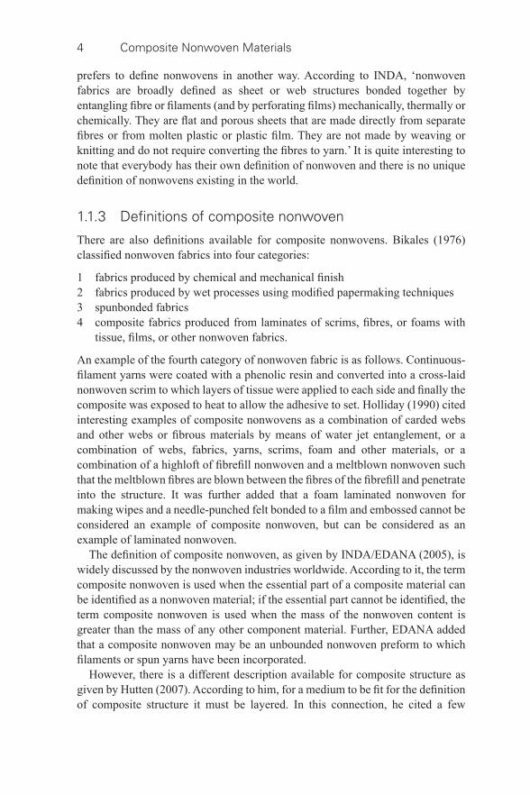
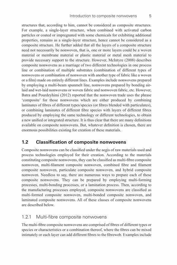
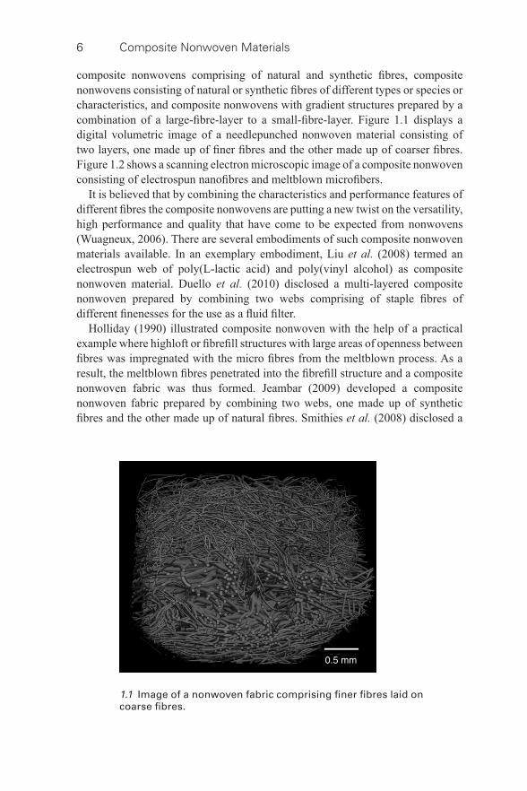
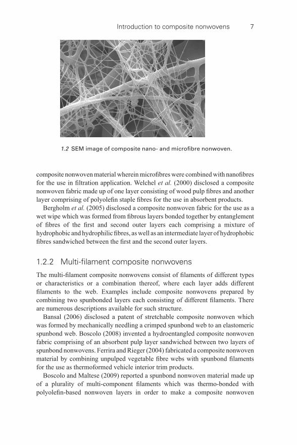
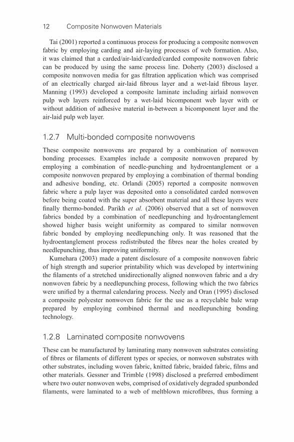
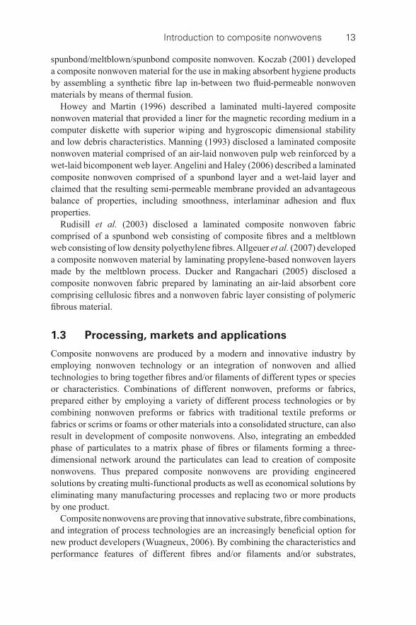
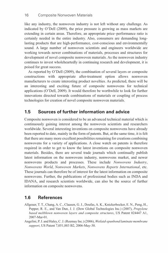
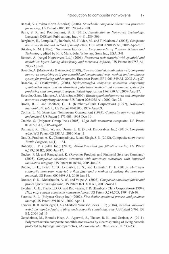
composite nonwovens comprising of natural and synthetic fi bres, composite nonwovens consisting of natural or synthetic fi bres of different types or species or characteristics, and composite nonwovens with gradient structures prepared by a combination of a large- fi bre-layer to a small- fi bre-layer. Figure 1.1 displays a digital volumetric image of a needlepunched nonwoven material consisting of two layers, one made up of fi ner fi bres and the other made up of coarser fi bres. Figure 1.2 shows a scanning electron microscopic image of a composite nonwoven consisting of electrospun nanofi bres and meltblown microfi bers.
It is believed that by combining the characteristics and performance features of different fi bres the composite nonwovens are putting a new twist on the versatility, high performance and quality that have come to be expected from nonwovens (Wuagneux, 2006). There are several embodiments of such composite nonwoven materials available. In an exemplary embodiment, Liu et al. (2008) termed an electrospun web of poly(L-lactic acid) and poly(vinyl alcohol) as composite nonwoven material. Duello et al. (2010) disclosed a multi- layered composite nonwoven prepared by combining two webs comprising of staple fi bres of different fi nenesses for the use as a fl uid fi lter.
Holliday (1990) illustrated composite nonwoven with the help of a practical example where highloft or fi brefi ll structures with large areas of openness between fi bres was impregnated with the micro fi bres from the meltblown process. As a result, the meltblown fi bres penetrated into the fi brefi ll structure and a composite nonwoven fabric was thus formed. Jeambar (2009) developed a composite nonwoven fabric prepared by combining two webs, one made up of synthetic fi bres and the other made up of natural fi bres. Smithies et al. (2008) disclosed a
1.1 Image of a nonwoven fabric comprising fi ner fi bres laid on coarse fi bres.
Introduction to composite nonwovens 7
composite nonwoven material wherein microfi bres were combined with nanofi bres for the use in fi ltration application. Welchel et al. (2000) disclosed a composite nonwoven fabric made up of one layer consisting of wood pulp fi bres and another layer comprising of polyolefi n staple fi bres for the use in absorbent products.
Bergholm et al. (2005) disclosed a composite nonwoven fabric for the use as a wet wipe which was formed from fi brous layers bonded together by entanglement of fi bres of the fi rst and second outer layers each comprising a mixture of hydrophobic and hydrophilic fi bres, as well as an intermediate layer of hydrophobic fi bres sandwiched between the fi rst and the second outer layers.
1.2.2 Multi- fi lament composite nonwovens
The multi- fi lament composite nonwovens consist of fi laments of different types or characteristics or a combination thereof, where each layer adds different fi laments to the web. Examples include composite nonwovens prepared by combining two spunbonded layers each consisting of different fi laments. There are numerous descriptions available for such structure.
Bansal (2006) disclosed a patent of stretchable composite nonwoven which was formed by mechanically needling a crimped spunbond web to an elastomeric spunbond web. Boscolo (2008) invented a hydroentangled composite nonwoven fabric comprising of an absorbent pulp layer sandwiched between two layers of spunbond nonwovens. Ferrira and Rieger (2004) fabricated a composite nonwoven material by combining unpulped vegetable fi bre webs with spunbond fi laments for the use as thermoformed vehicle interior trim products.
Boscolo and Maltese (2009) reported a spunbond nonwoven material made up of a plurality of multi- component fi laments which was thermo- bonded with polyolefi n- based nonwoven layers in order to make a composite nonwoven
1.2 SEM image of composite nano- and microfi bre nonwoven.
8 Composite Nonwoven Materials
fabric, particularly suitable for hygiene application. Ferencz (2002) developed a composite nonwoven fabric comprising one or more fi ne denier spunbond layers and one or more barrier layers. Newkirk et al. (2002) disclosed a composite nonwoven fabric with areas of different basis weights prepared by combining different layers of spunbond nonwovens for the use in hygiene products.
1.2.3 Combined fi bre and fi lament composite nonwovens
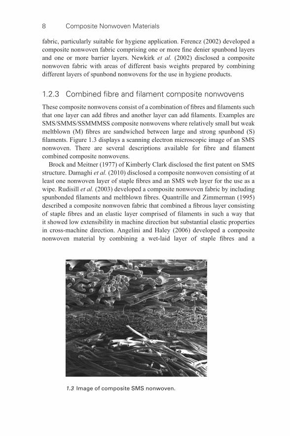
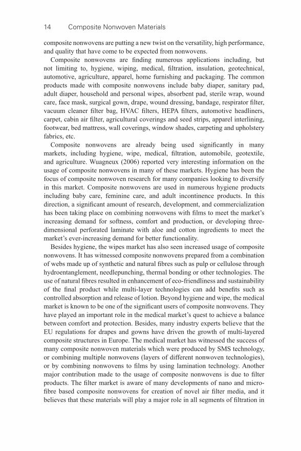
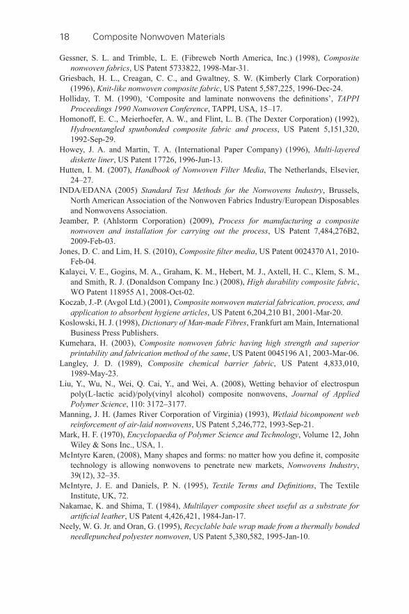
These composite nonwovens consist of a combination of fi bres and fi laments such that one layer can add fi bres and another layer can add fi laments. Examples are SMS/SMMS/SSMMMSS composite nonwovens where relatively small but weak meltblown (M) fi bres are sandwiched between large and strong spunbond (S) fi laments. Figure 1.3 displays a scanning electron microscopic image of an SMS nonwoven. There are several descriptions available for fi bre and fi lament combined composite nonwovens.
Brock and Meitner (1977) of Kimberly Clark disclosed the fi rst patent on SMS structure. Damaghi et al. (2010) disclosed a composite nonwoven consisting of at least one nonwoven layer of staple fi bres and an SMS web layer for the use as a wipe. Rudisill et al. (2003) developed a composite nonwoven fabric by including spunbonded fi laments and meltblown fi bres. Quantrille and Zimmerman (1995) described a composite nonwoven fabric that combined a fi brous layer consisting of staple fi bres and an elastic layer comprised of fi laments in such a way that it showed low extensibility in machine direction but substantial elastic properties in cross- machine direction. Angelini and Haley (2006) developed a composite nonwoven material by combining a wet- laid layer of staple fi bres and a
1.3 Image of composite SMS nonwoven.
Introduction to composite nonwovens 9
spunbond layer of continuous fi laments. Homonoff et al. (1992) described a hydroentangled composite nonwoven fabric comprising of a combination of spunbond web consisting of continuous synthetic fi laments and wet- laid wood pulp fi brous web consisting of staple fi bres.
Jones and Lim (2010), in an exemplary embodiment, disclosed a composite nonwoven material comprised of nanofi bres and spunbonded fi laments for the use in fi ltration applications. Bonneh (2006) developed a composite structure consisting of a spunlaid continuous fi lament layer and a meltblown staple fi bre layer, which, upon subjected to water jet treatment, resulted in the breaking of meltblown fi bres and caused the broken ends to extend through the spunlaid layer, thus forming a composite nonwoven fabric for use in absorbent products. Smithies et al. (2010) disclosed a patent on composite nonwoven material that included a nanofi bre layer deposited onto a spunbond layer consisting of continuous fi laments for the use in air fi ltration application.
Everhart et al. (1994) fi led a patent on high pulp content composite nonwoven fabric which was prepared by hydroentanglement of a pulp fi bre layer to a continuous fi lament substrate. Griesbach et al. (1996) described a composite nonwoven fabric prepared by hydroentanglement of two fi lamentous web layers and a cellulosic layer containing cellulosic fi bres. Vuillaume and Noelle (2007) disclosed an invention on a composite nonwoven fabric prepared by hydroentangling a cellulosic fi bre layer sandwiched between two webs of spunbonded fi laments. Stralin et al. (2011) reported a hydroentangled integrated composite nonwoven material including a mixture of randomized continuous fi laments and synthetic staple fi bres. Duncan et al. (2003) disclosed a composite nonwoven fabric manufactured by joining a fi brous web that was comprised of wood fi bres or a mixture of wood fi bres and synthetic fi bres to a spunlaid nonwoven by means of hydroentaglement.
In a US patent entitled ‘composite nonwoven fabrics’, Gessner and Trimble (1998) described a composite nonwoven fabric prepared by laminating two oxidatively degraded spunbond nonwoven webs of thermoplastic fi laments to a meltblown web of microfi bres, thus forming a spunbond/meltblown/spunbond composite nonwoven fabric for numerous applications, including medical garments and disposable absorbent products. Stranqvist (2005) disclosed an invention of hydroentangled composite nonwoven material prepared by combining layers of continuous fi laments, synthetic staple fi bres and natural fi bres.
1.2.4 Particulate composite nonwovens
The particulate composite nonwovens are prepared by embedding particulate matters into nonwoven structures. The particulate matters of interest are activated carbon, super absorbent powders, metal ions, biocides, antimicrobials, abrasive particles, preservative agents, wetting chemicals, etc. Examples include composite nonwoven with immobilized particulate matter, composite nonwoven with one
10 Composite Nonwoven Materials
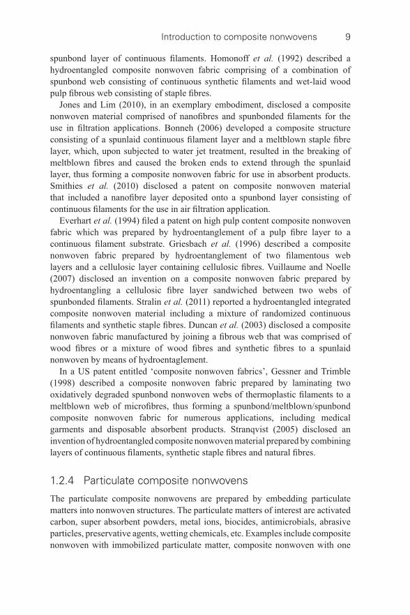
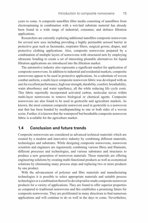
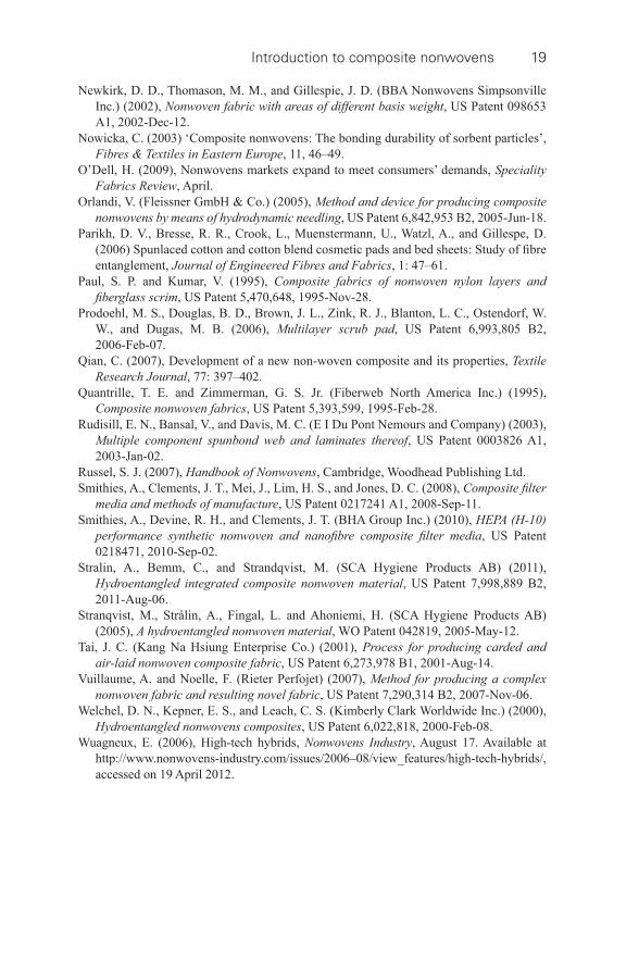
partially densifi ed web, composite nonwoven with two partially densifi ed webs, and composite nonwovens with different functional particulate matters immobilized and microfi bre webs in contact. Figure 1.4 displays a scanning electron microscopic image of activated carbon- particle-embedded microfi bre composite nonwoven. Nowicka (2003) reported a series of composite nonwoven materials prepared by incorporating powder- sorbent particles such as carbon, chitosan and aluminium oxide in meltblown nonwovens. Kalayci et al. (2008) disclosed a composite nonwoven fabric consisting of elastomeric nanofi bres and at least one type of active particle for the use as protective garments.
1.2.5 Hybrid composite nonwovens
The hybrid composite nonwovens are prepared by combining nonwovens with other materials such as woven, knitted and braided fabrics, fi lms, scrims, foams with tissue, etc. Qian (2007) developed a novel three- layer composite material by hydroentangling a woven fabric layer sandwiched between two nonwoven layers for the use as synthetic leather. Recently, Gensheimer et al. (2011) developed a polymer/bacteria composite nanofi bre nonwoven by electrospinning of living bacteria by hydrogel microparticles for manifold new applications, including microbial fuel cells, biotechnical synthesis and environmental remediation.
Nakamae and Shima (1984) described a hybrid composite nonwoven for acting as a substrate for artifi cial leather, which was prepared by hydroentangling three layers among which the fi rst layer was a meltblown web of very fi ne fi bres, the
1.4 Image of activated carbon and microfi bre based composite nonwoven.
Introduction to composite nonwovens 11
second one was made up of staple fi bres, and the base layer was made up of woven or knitted fabric. Langley (1989) reported a multi- layered composite chemical barrier fabric, which was prepared by adhesive bonding of a nonwoven polypropylene fabric sandwiched between two layers of polymer multi- layered fi lms. Paul and Kumar (1995) described a composite carpet- backing material consisting of a fi breglass scrim reinforced into two layers of nylon nonwoven fabric. Prodoehl et al. (2006) disclosed a multi- layer scrub pad comprising a spunbond scrubbing layer, an air- laid absorbent core layer and a laminated thermoplastic/cellulosic wiping layer.
1.2.6 Multi- formed composite nonwovens
These can be manufactured by employing more than one forming section adding different fi bres or fi laments to the web. The processes include multi- card, multi- forming box air- lay, multi- forming box wet- lay, multi- beam spunbond, and multi- beam meltblown process, or combinations of various forming processes. Examples are SMS/SMMS/SSMMMSS composite nonwovens, CoForm composite non-wovens, prepared by a combination of carded, air- laid, and carded layers and bonded by the through- air bonding process. As known, the benefi ts of combining spun bond and meltblown webs are observed in surgical gowns, respirator fi lter, etc. (Russel, 2007).
Manning (1993) described a composite nonwoven material prepared by combining an air- laid nonwoven pulp web and a wet- laid bicomponent web layer by means of heat or chemical treatment. Angelini and Haley (2006) disclosed a composite nonwoven material which was prepared by combining a spunbond layer and a wet- laid layer and laminating thereafter for the use as a semipermeable membrane support. Jeambar (2009) disclosed a composite nonwoven fabric which was prepared by combining a carded web comprised of synthetic fi bres and a wet- laid web of short natural fi bres and then bonding by employing the hydroentanglement process. Homonoff et al. (1992) described a composite nonwoven fabric which was prepared by combining a spunbond web and a wet- laid fi brous web and bonding by employing the hydroentanglement process. Boscolo (2008) disclosed a composite nonwoven fabric prepared by hydroentangling a pre- consolidated spunbonded web, an absorbent pulp layer, and a carded or spunbonded cover layer.
In another embodiment, Collins (1995) disclosed a composite nonwoven material prepared by hydroentanglement of a carded web and a series of spunbonded nonwovens. Bonneh (2006) developed a composite nonwoven fabric by combining a spunlaid continuous fi lament layer and a meltblown staple fi bre layer and bonding them by means of hydroentanglement. Crainic (2005) disclosed a highbulk composite nonwoven prepared by combining a hydro-entangled binder fi bre layer to a nonwoven layer issued from forming heads also consisting of binder fi bres by means of the through- air bonding process.
12 Composite Nonwoven Materials
Tai (2001) reported a continuous process for producing a composite nonwoven fabric by employing carding and air- laying processes of web formation. Also, it was claimed that a carded/air- laid/carded/carded composite nonwoven fabric can be produced by using the same process line. Doherty (2003) disclosed a composite nonwoven media for gas fi ltration application which was comprised of an electrically charged air- laid fi brous layer and a wet- laid fi brous layer. Manning (1993) developed a composite laminate including airlaid nonwoven pulp web layers reinforced by a wet- laid bicomponent web layer with or without addition of adhesive material in- between a bicomponent layer and the air- laid pulp web layer.
1.2.7 Multi- bonded composite nonwovens
These composite nonwovens are prepared by a combination of nonwoven bonding processes. Examples include a composite nonwoven prepared by employing a combination of needle- punching and hydroentanglement or a composite nonwoven prepared by employing a combination of thermal bonding and adhesive bonding, etc. Orlandi (2005) reported a composite nonwoven fabric where a pulp layer was deposited onto a consolidated carded nonwoven before being coated with the super absorbent material and all these layers were fi nally thermo- bonded. Parikh et al. (2006) observed that a set of nonwoven fabrics bonded by a combination of needlepunching and hydroentanglement showed higher basis weight uniformity as compared to similar nonwoven fabric bonded by employing needlepunching only. It was reasoned that the hydroentanglement process redistributed the fi bres near the holes created by needlepunching, thus improving uniformity.
Kumehara (2003) made a patent disclosure of a composite nonwoven fabric of high strength and superior printability which was developed by intertwining the fi laments of a stretched unidirectionally aligned nonwoven fabric and a dry nonwoven fabric by a needlepunching process, following which the two fabrics were unifi ed by a thermal calendaring process. Neely and Oran (1995) disclosed a composite polyester nonwoven fabric for the use as a recyclable bale wrap prepared by employing combined thermal and needlepunching bonding technology.
1.2.8 Laminated composite nonwovens
These can be manufactured by laminating many nonwoven substrates consisting of fi bres or fi laments of different types or species, or nonwoven substrates with other substrates, including woven fabric, knitted fabric, braided fabric, fi lms and other materials. Gessner and Trimble (1998) disclosed a preferred embodiment where two outer nonwoven webs, comprised of oxidatively degraded spunbonded fi laments, were laminated to a web of meltblown microfi bres, thus forming a
Introduction to composite nonwovens 13
spunbond/meltblown/spunbond composite nonwoven. Koczab (2001) developed a composite nonwoven material for the use in making absorbent hygiene products by assembling a synthetic fi bre lap in- between two fl uid- permeable nonwoven materials by means of thermal fusion.
Howey and Martin (1996) described a laminated multi- layered composite nonwoven material that provided a liner for the magnetic recording medium in a computer diskette with superior wiping and hygroscopic dimensional stability and low debris characteristics. Manning (1993) disclosed a laminated composite nonwoven material comprised of an air- laid nonwoven pulp web reinforced by a wet- laid bicomponent web layer. Angelini and Haley (2006) described a laminated composite nonwoven comprised of a spunbond layer and a wet- laid layer and claimed that the resulting semi- permeable membrane provided an advantageous balance of properties, including smoothness, interlaminar adhesion and fl ux properties.
Rudisill et al. (2003) disclosed a laminated composite nonwoven fabric comprised of a spunbond web consisting of composite fi bres and a meltblown web consisting of low density polyethylene fi bres. Allgeuer et al. (2007) developed a composite nonwoven material by laminating propylene- based nonwoven layers made by the meltblown process. Ducker and Rangachari (2005) disclosed a composite nonwoven fabric prepared by laminating an air- laid absorbent core comprising cellulosic fi bres and a nonwoven fabric layer consisting of polymeric fi brous material.
1.3 Processing, markets and applications
Composite nonwovens are produced by a modern and innovative industry by employing nonwoven technology or an integration of nonwoven and allied technologies to bring together fi bres and/or fi laments of different types or species or characteristics. Combinations of different nonwoven, preforms or fabrics, prepared either by employing a variety of different process technologies or by combining nonwoven preforms or fabrics with traditional textile preforms or fabrics or scrims or foams or other materials into a consolidated structure, can also result in development of composite nonwovens. Also, integrating an embedded phase of particulates to a matrix phase of fi bres or fi laments forming a three- dimensional network around the particulates can lead to creation of composite nonwovens. Thus prepared composite nonwovens are providing engineered solutions by creating multi- functional products as well as economical solutions by eliminating many manufacturing processes and replacing two or more products by one product.
Composite nonwovens are proving that innovative substrate, fi bre combinations, and integration of process technologies are an increasingly benefi cial option for new product developers (Wuagneux, 2006). By combining the characteristics and performance features of different fi bres and/or fi laments and/or substrates,
14 Composite Nonwoven Materials
composite nonwovens are putting a new twist on the versatility, high performance, and quality that have come to be expected from nonwovens.
Composite nonwovens are fi nding numerous applications including, but not limiting to, hygiene, wiping, medical, fi ltration, insulation, geotechnical, automotive, agriculture, apparel, home furnishing and packaging. The common products made with composite nonwovens include baby diaper, sanitary pad, adult diaper, household and personal wipes, absorbent pad, sterile wrap, wound care, face mask, surgical gown, drape, wound dressing, bandage, respirator fi lter, vacuum cleaner fi lter bag, HVAC fi lters, HEPA fi lters, automotive headliners, carpet, cabin air fi lter, agricultural coverings and seed strips, apparel interlining, footwear, bed mattress, wall coverings, window shades, carpeting and upholstery fabrics, etc.
Composite nonwovens are already being used signifi cantly in many markets, including hygiene, wipe, medical, fi ltration, automobile, geotextile, and agriculture. Wuagneux (2006) reported very interesting information on the usage of composite nonwovens in many of these markets. Hygiene has been the focus of composite nonwoven research for many companies looking to diversify in this market. Composite nonwovens are used in numerous hygiene products including baby care, feminine care, and adult incontinence products. In this direction, a signifi cant amount of research, development, and commercialization has been taking place on combining nonwovens with fi lms to meet the market’s increasing demand for softness, comfort and production, or developing three- dimensional perforated laminate with aloe and cotton ingredients to meet the market’s ever- increasing demand for better functionality.
Besides hygiene, the wipes market has also seen increased usage of composite nonwovens. It has witnessed composite nonwovens prepared from a combination of webs made up of synthetic and natural fi bres such as pulp or cellulose through hydroentanglement, needlepunching, thermal bonding or other technologies. The use of natural fi bres resulted in enhancement of eco- friendliness and sustainability of the fi nal product while multi- layer technologies can add benefi ts such as controlled absorption and release of lotion. Beyond hygiene and wipe, the medical market is known to be one of the signifi cant users of composite nonwovens. They have played an important role in the medical market’s quest to achieve a balance between comfort and protection. Besides, many industry experts believe that the EU regulations for drapes and gowns have driven the growth of multi- layered composite structures in Europe. The medical market has witnessed the success of many composite nonwoven materials which were produced by SMS technology, or combining multiple nonwovens (layers of different nonwoven technologies), or by combining nonwovens to fi lms by using lamination technology. Another major contribution made to the usage of composite nonwovens is due to fi lter products. The fi lter market is aware of many developments of nano and micro- fi bre based composite nonwovens for creation of novel air fi lter media, and it believes that these materials will play a major role in all segments of fi ltration in
Introduction to composite nonwovens 15
years to come. A composite nanofi bre fi lter media consisting of nanofi bres from electrospinning in combination with a wet- laid substrate material has already been found in a wide range of industrial, consumer, and defence fi ltration applications.
Researchers are currently exploring additional nanofi bre composite nonwovens for several new uses including providing a highly permeable aerosol barrier in protective gear such as facemasks, respirator fi lters, surgical gowns, drapes, and protective clothing applications. Also, composite nonwovens prepared by a combination of multiple layers of nonwovens with structured nets by employing ultrasonic bonding to create a set of interesting pleatable alternatives for liquid fi ltration applications are introduced into the fi ltration market.
The automotive industry also represents a signifi cant market for application of composite nonwovens. In addition to industrial and residential markets, composite nonwovens appear to be used in protective applications. As a substitute of woven combat uniform, a multi- layer composite nonwoven fabric was developed with an aim for excellent performance, high tear strength, durability, comfort, breathability, water absorbency and water repellency, all the while reducing life cycle costs. This fabric reportedly incorporated activated carbon, molecular sieves within multi- layer nonwovens to remove biological or chemical agents. Composite nonwovens are also found to be used in geotextile and agriculture markets. As known, the most common composite nonwoven used in geotextile is a nonwoven mat that has been bonded by needlepunching to one or both sides of a woven scrim. Further, it is known that the waterproof but breathable composite nonwoven fabric is available for the agriculture market.
1.4 Conclusion and future trends
Composite nonwovens are considered as advanced technical materials which are created by a modern and innovative industry by combining different materials, technologies and substrates. While designing composite nonwovens, nonwoven scientists and engineers are ingeniously combining various fi bres and fi laments, different processes and technologies, and various substrates and structures to produce a new generation of nonwoven materials. These materials are offering engineering solutions by creating multi- functional products as well as economical solutions by eliminating many process steps and replacing two or more products by one product.
With the advancement of polymer and fi bre materials and manufacturing technologies it is possible to select appropriate materials and suitable process technologies or a combination thereof to develop tailor- made composite nonwoven products for a variety of applications. They are found to offer superior properties as compared to traditional nonwovens and this establishes a promising future for composite nonwovens. They are proliferated in many directions to fi nd numerous applications and will continue to do so well in the days to come. Nevertheless,
16 Composite Nonwoven Materials
like any industry, the nonwoven industry is not left without any challenge. As indicated by O’Dell (2009), the price pressure is growing as mass markets are extending in certain areas. Therefore, an appropriate price–performance ratio is certainly needed in the entire industry. Also, consumers are demanding long- lasting products that are high- performance, cost- conscious and environmentally sound. A large number of nonwoven scientists and engineers worldwide are working towards newer combinations of materials, processes and structures for development of novel composite nonwoven materials. As the nonwoven industry continues to invest wholeheartedly in continuing research and development, it is poised for great success.
As reported by O’Dell (2009), the combination of several layers or composite constructions with appropriate after- treatment option allows nonwoven manufacturers to create interesting product novelties. As predicted, there will be an interesting and exciting future of composite nonwovens for technical applications (O’Dell, 2009). It would therefore be worthwhile to look for further innovations directed towards combinations of materials or coupling of process technologies for creation of novel composite nonwoven materials.
1.5 Sources of further information and advice
Composite nonwoven is considered to be an advanced technical material which is continuously gaining interest among the nonwoven scientists and researchers worldwide. Several interesting inventions on composite nonwovens have already been reported to date, mainly in the form of patents. But, at the same time, it is felt that there are many more excellent possibilities remaining for creations combining nonwovens for a variety of applications. A close watch on patents is therefore required in order to get to know the latest inventions on composite nonwoven materials. Besides, there are several trade journals which continually publish latest information on the nonwovens industry, nonwovens market, and newer nonwovens products and processes. These include Nonwovens Industry , Nonwovens World , Nonwoven Markets , Nonwovens Reports International , etc. These journals can therefore be of interest for the latest information on composite nonwovens. Further, the publications of professional bodies such as INDA and IDANA, and research scientists worldwide, can also be the source of further information on composite nonwovens.
1.6 References
Allgeuer , T. T. , Chang , A. C. , Claasen , G. J. , Doufas , A. K. , Knickerbocker , E. N. , Peng , H. , Pepper , R. E. , and Van Dun , J. J. (Dow Global Technologies Inc.) ( 2007 ), Propylene based meltblown nonwoven layers and composite structures , US Patent 024447 A1 , 2007-Mar-01.
Angelini , P. J. and Haley , C. J. (Reemay Inc.) ( 2006 ), Wetlaid- spunbond laminate membrane support , US Patent 7,051,883 B2 , 2006-May-30.
Introduction to composite nonwovens 17
Bansal , V. (Invista North America) ( 2006 ), Stretchable composite sheets and processes for making , US Patent 7,005,395 , 2006-Feb-28.
Batra , S. K. and Pourdeyhimi , B. P. ( 2012 ), Introduction to Nonwoven Technology , Lancaster , DEStech Publications, Inc. , 4 – 11 , 289 – 306 .
Bergholm , H. , Lampula , E. , Rahhola , M. , Hulden , M. , and Tiirikainen , J. ( 2005 ), Composite nonwoven its use and method of manufacture , US Patent 0090175 A1 , 2005-Apr-28.
Bikales , N. M. ( 1976 ), ‘ Nonwoven fabrics ’, in Encyclopaedia of Polymer Science and Technology , edited by H. F. Mark , John Wiley and Sons Inc. , USA , 341 .
Bonneh , A. (Avgol Nonwovens Ltd.) ( 2006 ), Nonwoven web material with spunlaid and meltblown layers having absorbency and increased softness , US Patent 040753 A1 , 2006-Apr-20.
Boscolo , A. (Matkowska & Associes) ( 2008 ), Pre- consolidated spunbonded web, composite nonwoven omprising said pre- consolidated spunbonded web, method and continuous system for producing said composite , European Patent EP 1,961,849 A1 , 2008-Aug-27.
Boscolo , G. (Matkowska) ( 2008 ), Hydroentangled composite nonwoven comprising spunbonded layer and an absorbent pulp layer, method and continuous system for producing said composite , European Patent Application 1961850 A1 , 2008-Aug-27.
Boscolo , G. and Maltese , A. (Albis Spa) ( 2009 ), Elastic spunbond nonwoven and composite nonwoven comprising the same , US Patent 0264038 A1 , 2009-Oct-22.
Brock , R. J. and Meitner , G. H. (Kimberly-Clark Corporation) ( 1977 ), Nonwoven thermoplastic fabric , US Patent 4041203 , 1977-Aug-09.
Collins , L. M. (American Nonwovens Corporation) ( 1995 ), Composite nonwoven fabric and method , US Patent 5,475,903 , 1995-Dec-19.
Crainic , S. (Polymer Group Inc.) ( 2005 ), High bulk nonwoven composite , US Patent 0170728 A1 , 2005-Aug-05.
Damaghi , R. , Child , W. , and Duane , L. E. (Nutek Disposables Inc.) ( 2010 ), Composite wipe , WO Patent 028238 A1 , 2010-Mar-11.
Das , D. , Pradhan , A. K. , Chattopadhyay , R. and Singh , S. N. ( 2012 ), Composite nonwovens , Textile Progress , 44 ( 1 ), 1 – 84 .
Doherty , J. P. (Lydall Inc.) ( 2003 ), Air- laid/wet- laid gas fi ltration media , US Patent 6,579,350 B2 , 2003-Jun-17.
Ducker , P. M. and Rangachari , K. (Rayonier Products and Financial Services Company) ( 2005 ), Composite absorbent structures with nonwoven substrates with improved lamination integrity , US Patent 0118916 , 2005-Jun-02.
Duello , L. E. , Peart , C. B. , Lemaster , H. S. , and Lemaster , D. E. ( 2010 ), Multilayer composite nonwoven material, a fl uid fi lter and a method of making the nonwoven material , US Patent 0006498 A1 , 2010-Jan-14.
Duncan , G. K. , Meierhoefer , A. W. , and Volpe , A. ( 2003 ), Composite nonwoven fabric and process for its manufacture , US Patent 0211800 A1 , 2003-Nov-13.
Everhart , C. H. , Fischer , D. O. , and Radwanski , F. R. (Kimberly Clark Corporation) ( 1994 ), High pulp content composite nonwoven fabric , US Patent 5,284,703 , 1994-Feb-08.
Ferencz , R. L. (Polymer Group Inc.) ( 2002 ), Fine denier spunbond process and products thereof , US Patent 29146 A1 , 2002-Apr-11.
Ferreira , R. B. and Rieger , J. A. (Ahlstorm Windsor Locks LLC) ( 2004 ), Wet- laid nonwoven web from unpulped natural fi bres and composite containing same , US Patent 6,762,138 B2 , 2004-Jul-13.
Gensheimer , M. , Brandis-Heep , A. , Agarwal , S. , Thauer , R. K. , and Greiner , A. ( 2011 ), Polymer/bacteria composite nanofi bre nonwovens by electrospinning of living bacteria protected by hydrogel microparticlres , Macromolecular Bioscience , 11 : 333 – 337 .
18 Composite Nonwoven Materials
Gessner , S. L. and Trimble , L. E. (Fibreweb North America, Inc.) ( 1998 ), Composite nonwoven fabrics , US Patent 5733822 , 1998-Mar-31.
Griesbach , H. L. , Creagan , C. C. , and Gwaltney , S. W. (Kimberly Clark Corporation) ( 1996 ), Knit- like nonwoven composite fabric , US Patent 5,587,225 , 1996-Dec-24.
Holliday , T. M. ( 1990 ), ‘ Composite and laminate nonwovens the defi nitions ’, TAPPI Proceedings 1990 Nonwoven Conference , TAPPI , USA , 15 – 17 .
Homonoff , E. C. , Meierhoefer , A. W. , and Flint , L. B. (The Dexter Corporation) ( 1992 ), Hydroentangled spunbonded composite fabric and process , US Patent 5,151,320 , 1992-Sep-29.
Howey , J. A. and Martin , T. A. (International Paper Company) ( 1996 ), Multi- layered diskette liner , US Patent 17726 , 1996-Jun-13.
Hutten , I. M. ( 2007 ), Handbook of Nonwoven Filter Media , The Netherlands , Elsevier , 24 – 27 .
INDA/EDANA ( 2005 ) Standard Test Methods for the Nonwovens Industry , Brussels , North American Association of the Nonwoven Fabrics Industry/European Disposables and Nonwovens Association .
Jeamber , P. (Ahlstorm Corporation) ( 2009 ), Process for manufacturing a composite nonwoven and installation for carrying out the process , US Patent 7,484,276B2 , 2009-Feb-03.
Jones , D. C. and Lim , H. S. ( 2010 ), Composite fi lter media , US Patent 0024370 A1 , 2010-Feb-04.
Kalayci , V. E. , Gogins , M. A. , Graham , K. M. , Hebert , M. J. , Axtell , H. C. , Klem , S. M. , and Smith , R. J. (Donaldson Company Inc.) ( 2008 ), High durability composite fabric , WO Patent 118955 A1 , 2008-Oct-02.
Koczab , J.-P. (Avgol Ltd.) ( 2001 ), Composite nonwoven material fabrication, process, and application to absorbent hygiene articles , US Patent 6,204,210 B1 , 2001-Mar-20.
Koslowski , H. J. ( 1998 ), Dictionary of Man- made Fibres , Frankfurt am Main , International Business Press Publishers .
Kumehara , H. ( 2003 ), Composite nonwoven fabric having high strength and superior printability and fabrication method of the same , US Patent 0045196 A1 , 2003-Mar-06.
Langley , J. D. ( 1989 ), Composite chemical barrier fabric , US Patent 4,833,010 , 1989-May-23.
Liu , Y. , Wu , N. , Wei , Q. Cai , Y. , and Wei , A. ( 2008 ), Wetting behavior of electrospun poly(L-lactic acid)/poly(vinyl alcohol) composite nonwovens , Journal of Applied Polymer Science , 110 : 3172 – 3177 .
Manning , J. H. (James River Corporation of Virginia) ( 1993 ), Wetlaid bicomponent web reinforcement of air- laid nonwovens , US Patent 5,246,772 , 1993-Sep-21.
Mark , H. F. ( 1970 ), Encyclopaedia of Polymer Science and Technology , Volume 12 , John Wiley & Sons Inc. , USA , 1 .
McIntyre Karen , ( 2008 ), Many shapes and forms: no matter how you defi ne it, composite technology is allowing nonwovens to penetrate new markets , Nonwovens Industry , 39 ( 12 ), 32 – 35 .
McIntyre , J. E. and Daniels , P. N. ( 1995 ), Textile Terms and Defi nitions , The Textile Institute , UK , 72 .
Nakamae , K. and Shima , T. ( 1984 ), Multilayer composite sheet useful as a substrate for artifi cial leather , US Patent 4,426,421 , 1984 - Jan - 17 .
Neely , W. G. Jr. and Oran , G. ( 1995 ), Recyclable bale wrap made from a thermally bonded needlepunched polyester nonwoven , US Patent 5,380,582 , 1995 - Jan - 10 .
Introduction to composite nonwovens 19
Newkirk , D. D. , Thomason , M. M. , and Gillespie , J. D. (BBA Nonwovens Simpsonville Inc.) ( 2002 ), Nonwoven fabric with areas of different basis weight , US Patent 098653 A1 , 2002-Dec-12.
Nowicka , C. ( 2003 ) ‘ Composite nonwovens: The bonding durability of sorbent particles ’, Fibres & Textiles in Eastern Europe, 11 , 46 – 49 .
O’Dell , H. ( 2009 ), Nonwovens markets expand to meet consumers’ demands , Speciality Fabrics Review , April .
Orlandi , V. (Fleissner GmbH & Co.) ( 2005 ), Method and device for producing composite nonwovens by means of hydrodynamic needling , US Patent 6,842,953 B2 , 2005-Jun-18.
Parikh , D. V. , Bresse , R. R. , Crook , L. , Muenstermann , U. , Watzl , A. , and Gillespe , D. ( 2006 ) Spunlaced cotton and cotton blend cosmetic pads and bed sheets: Study of fi bre entanglement , Journal of Engineered Fibres and Fabrics , 1 : 47 – 61 .
Paul , S. P. and Kumar , V. ( 1995 ), Composite fabrics of nonwoven nylon layers and fi berglass scrim , US Patent 5,470,648 , 1995 - Nov - 28 .
Prodoehl , M. S. , Douglas , B. D. , Brown , J. L. , Zink , R. J. , Blanton , L. C. , Ostendorf , W. W. , and Dugas , M. B. ( 2006 ), Multilayer scrub pad , US Patent 6,993,805 B2 , 2006 - Feb - 07 .
Qian , C. ( 2007 ), Development of a new non- woven composite and its properties , Textile Research Journal , 77 : 397 – 402 .
Quantrille , T. E. and Zimmerman , G. S. Jr. (Fiberweb North America Inc.) ( 1995 ), Composite nonwoven fabrics , US Patent 5,393,599 , 1995 - Feb - 28 .
Rudisill , E. N. , Bansal , V. , and Davis , M. C. (E I Du Pont Nemours and Company) ( 2003 ), Multiple component spunbond web and laminates thereof , US Patent 0003826 A1 , 2003 - Jan - 02 .
Russel , S. J. ( 2007 ), Handbook of Nonwovens , Cambridge , Woodhead Publishing Ltd . Smithies , A. , Clements , J. T. , Mei , J. , Lim , H. S. , and Jones , D. C. ( 2008 ), Composite fi lter
media and methods of manufacture , US Patent 0217241 A1 , 2008 - Sep - 11 . Smithies , A. , Devine , R. H. , and Clements , J. T. (BHA Group Inc.) ( 2010 ), HEPA (H-10)
performance synthetic nonwoven and nanofi bre composite fi lter media , US Patent 0218471 , 2010 - Sep - 02 .
Stralin , A. , Bemm , C. , and Strandqvist , M. (SCA Hygiene Products AB) ( 2011 ), Hydroentangled integrated composite nonwoven material , US Patent 7,998,889 B2 , 2011 - Aug - 06 .
Stranqvist , M. , Strålin , A. , Fingal , L. and Ahoniemi , H. (SCA Hygiene Products AB) ( 2005 ), A hydroentangled nonwoven material , WO Patent 042819 , 2005 - May - 12 .
Tai , J. C. (Kang Na Hsiung Enterprise Co.) ( 2001 ), Process for producing carded and air- laid nonwoven composite fabric , US Patent 6,273,978 B1 , 2001 - Aug - 14 .
Vuillaume , A. and Noelle , F. (Rieter Perfojet) ( 2007 ), Method for producing a complex nonwoven fabric and resulting novel fabric , US Patent 7,290,314 B2 , 2007 - Nov - 06 .
Welchel , D. N. , Kepner , E. S. , and Leach , C. S. (Kimberly Clark Worldwide Inc.) ( 2000 ), Hydroentangled nonwovens composites , US Patent 6,022,818 , 2000 - Feb - 08 .
Wuagneux , E. ( 2006 ), High- tech hybrids , Nonwovens Industry , August 17 . Available at http://www.nonwovens- industry.com/issues/2006–08/view_features/high- tech-hybrids/ , accessed on 19 April 2012.
20
© 2014 Woodhead Publishing Limited
2 Natural and synthetic fi bres for
composite nonwovens
S . MUKHOPADHYAY, Indian Institute of Technology Delhi, India
DOI: 10.1533/9780857097750.20
Abstract: This chapter reviews the use of natural and synthetic fi bres in composite nonwovens. It begins by reviewing the use of natural fi bres including the most widely used: cotton, jute, kenaf and fl ax. Most nonwoven fi bres are still, however, synthetic. The rest of the chapter discusses the use of polypropylene, polyester, polyethylene and nylon. The chapter concludes by reviewing the use of bicomponent fi bres to combine the properties of different fi bre types in maximising the functionality of nonwovens.
Key words: natural fi bres, synthetic, bicomponent.
2.1 Introduction
This chapter reviews the use of natural and synthetic fi bres in composite nonwovens. It begins by reviewing the use of natural fi bres including the most widely used: cotton, jute, kenaf and fl ax. Most nonwoven fi bres are still, however, synthetic. The rest of the chapter discusses the use of polypropylene, polyester, polyethylene and nylon. The chapter concludes by reviewing the use of bicomponent fi bres to combine the properties of different fi bre types in maximising the functionality of nonwovens.
2.2 Natural and biodegradable fi bres for nonwovens
The environmental impact of disposable products such as baby diapers, adult incontinence and feminine hygiene products has meant that there is growing interest in the use of natural or biodegradable fi bres. Natural fi bres for nonwovens include cotton, jute, kenaf and fl ax as well as smaller quantities of hemp, coir, sisal, milkweed, wood and some animal fi bres. Synthetic biodegradable fi bres that have also been used for nonwoven applications include: 1
• regenerated cellulosic fi bres such as cellulose acetate, rayon and lyocell; • synthetic fi bres fi bres such as polylactic acid (PLA), poly(caprolactone)
(PCL), poly(hydroxybutyrate) (PHB), poly(hydroxybutyrate- co-valerate) (PHBV), polytetramethylene adipate- co-terephthalate (PTAT) and poly(vinyl acetate) (PVA).
Among natural fi bres, cotton is most widely used for nonwoven applications 2 and it has been estimated that cotton accounts for 8% of the global market in
Natural and synthetic fi bres 21
nonwoven fi bre products. 3 The advantages of cotton include biodegradability, superior wet strength and a quick drying surface which is particularly useful for wipes. Bleached cotton fi bres are used because of their superior appearance and high levels of absorbency as well as being soft to the touch and breathable. 4 Uses of cotton nonwovens include disposable products such as swabs, wipes, fi lters, wadding, personal care products such as babies’ diapers and feminine hygiene products as well as semi- durable products such as bedding, pillow fi llers and household furnishings. An area of recent growth is spunlaced cotton fi bres for cosmetic wipes. Typical production techniques involve web formation using one of three techniques:
• dry laid process • wet laid process • polymer laid process (involving spun laid and melt blown web formation).
Bonding is achieved through needle punching, hydroentangling, stitchbonding and chemical or thermal bonding techniques. Cotton has been combined into bicomponent fi bres for nonwoven applications using fi bres such as lyocell and cellulose acetate. Biocomponent fi bre technology is discussed later in this chapter.
Useful properties of jute fi bres for nonwoven applications include high strength, modulus and dimensional stability as well as good moisture absorption and breathability. 5 Jute fi bres are typically pretreated to improve properties such as crimp to aid further processing. Manufacturing techniques for jute include stitch bonding, hot calandering, needle punching, thermal bonding and hydroentanglement. Needle punching is particularly suitable for developing nonwovens with properties such as good acoustic insulation. Applications of jute nonwovens include fl oor coverings (where they provide thermal and acoustic insulation), fi lters, composites and geotextiles. A particularly important application of jute nonwovens is automotive interiors (e.g. door, fl oor and boot lining materials) due to the combination of light weight, durability, low fl ammability and other mechanical properties such as drapability, tensile strength and impact performance.
Kenaf fi bres are typically pretreated to reduce stiffness, 6 while they may be blended with cotton, polyester and polypropylene. 7 Nonwoven mats are typically formed by the air laid process followed by needle punching and thermal bonding. Kenaf nonwoven mats are used in composites and geotextile applications as well as automotive interiors. 8 The high cellulose content and length of fl ax fi bres also makes them a good substitute for synthetic fi bres in disposable nonwovens. 9 Fibres are prepared by pulping and bleaching. They can then be processed using wet laying followed by hydroentangling or spunlacing. The wet laid process can result in poor fi bre formation in the web which can be corrected through good control of fi bre length and the use of appropriate fi bre fi nishes. Dry laid jute nonwovens have been shown to have more consistent properties. Applications of jute nonwovens include fi lters. 10
22 Composite Nonwoven Materials
2.3 Polypropylene and polyester fi bres
Polypropylene fi bres account for 60% of all the fi bres used for nonwoven production. They come under the general category of polyolefi ns. Filaments are produced from the polymer by melt- spinning. Generally, the polypropylene used in fi laments is of the iostactic variety while 65% of polypropylene fi bre nonwovens are used for hygiene applications. Its oleophilic nature makes the nonwoven fabric effi cient in absorbing and retaining oil from oil–water mixtures. Polypropylene fi bres have the advantages of being lightweight, dry (due to low moisture absorption) with good strength, good abrasion resistance, high modulus and good resistance to deterioration from chemicals and microorganisms as well as having a soft feel. Wettability can be improved by various treatments such as plasma treatment. Polypropylene has a major limitation in terms of its thermal properties – its low glass transition temperature and melting point restricts some potential applications.
Polyester is the second most widely used fi bre next to polypropylene in nonwoven production. Polyester is used in quilted fabrics, bedspreads and other home furnishings. The term polyester generally refers to polyethylene terephthalate or PET. There are also other polyester fi bres available such as polybutylene terephthalate (PBT) and polytrimethylene terephthalate (PTT). However PET is still the most widely used polyester fi bre. Polyester is mainly produced by melt spinning. Fibres are relatively strong and have between 60% and 85% crystallinity. The high crystallinity of polyester and the presence of the aromatic ring in the fi bre structure makes fi bres low in water absorption and resistance to acids and alkalis. The diameter of polyester fi bres most widely used to produce nonwovens and composite nonwovens varies from 0.38 to 50 μ m and a cut length of 0.9 to 150 mm.
The advantages of polyester fi bres include high strength, high modulus, high toughness, good abrasion resistance, good resilience, very low moisture absorbency, high melting temperature and heat distortion temperature, resistance to hazardous chemicals, oxygen barrier, inertness and biocompatibility. They can be processed using any of the main methods of nonwoven manufacture. The wettability of polyester fi bres can be improved by plasma treatment. 11
In a study on geotextiles by Abdelmalek et al. 12 the in- plane and cross- plane water- retention characteristics of polyester geotextiles was studied. The materials used in the investigation were continuous fi laments nonwoven needle punched polyester geotextiles varying in their apparent opening size. It was found that cross- plane water- retention data demonstrated their hydrophobic nature, with both specimens being essentially non- conductive to water beyond suction heads of 0.2–0.3 kPa. Both specimens exhibited signifi cant hysteresis in their water- retention function, such that at a given suction a geotextile contained more water when drying than when wetting.
Natural and synthetic fi bres 23
2.4 Polyethylene and nylon fi bres
Polyethylene (PE) is the second type of polyolefi n which is also used in nonwoven applications. Depending on the kind of structure, they are classifi ed as HDPE (high density polyethylene), LDPE (low density polyethylene) or LLDPE (linear low density polyethylene). There has been limited research on polyethylene nonwovens, but the pre- irradiation induced emulsion graft polymerisation method has been used to introduce acrylonitrile onto PE nonwoven fabrics. 13 In another study, Ma et al. 14 studied impregnation of nonwoven HDPE fi brous samples with a nonionic surfactant (N,N-dimethyldodecylamine N-oxide) using supercritical carbon dioxide as the solvent. The results showed that although the supercritical fl uid (SCF) was absorbed into the polymer, no structural changes or loss of mechanical strength was observed. The wetting properties of this highly hydrophobic material were signifi cantly improved.
Nylon is a polyamide. The most common types are nylon 6 and nylon 66. Nylon 6 is polymerised from caprolactam whereas nylon 66 is produced from hexamethylene diamine with adipic acid as the starting material. Both polymers are meltspun to form continuous fi laments. The most commonly used nylon fi bres have a diameter of 15 to 25 μ m. Nylon fi bres have low heat resistance and show poor conduction of heat. Their advantages in practical terms include high durability, relatively high glass transition and melting temperatures, high tensile and tear strengths, good elastic recovery and low static electric charge generation. Disadvantages include poor resistance to exposure to light and poor wet strength.
The physical properties of nylon 6 nonwoven mats produced from solutions with formic acid have been studied. 15 Nonwoven electrospun mats from various solutions with different concentrations were examined regarding their morpho l-ogy, pore size, surface area and gas transport properties. Each nonwoven material with average fi bre diameters from 90 to 500 nm was prepared under controlled electrospinning parameters. From the results, the authors observed that fi bre diameter was strongly affected by the polymer concentration (polymer viscosity). In addition, the results showed that the pore size and gas transport property of electrospun nylon 6 nonwoven mats were affected by fi bre diameter.
Saraf et al. 16 created a superhydrophobic/superoleophobic surface by preparing a metastable Cassie–Baxter (CB) surface. To create a CB surface it was essential to have low surface energy and properly constructed surface morphology. The researchers explored three different techniques to achieve superhydrophobicity and superoleophobicity using hydroentangled nylon nonwoven fabric: pulsed plasma polymerisation of 1H,1H,2H,2H-perfl uorodecyl acrylate (PFAC8), microwave- assisted condensation of 1H,1H,2H,2H-perfl uorodecyltrimethoxysi-lane (FS), and FS condensation through wet processing. Nonwoven fabric materials prepared using these three techniques were superhydrophobic and superoleophobic as shown by their very high contact angles for both water (contact angles of 168–174°) and dodecane (contact angles of 153–160°).
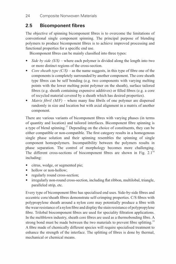
24 Composite Nonwoven Materials
2.5 Bicomponent fi bres
The objective of spinning bicomponent fi bres is to overcome the limitations of conventional single component spinning. The principal purpose of blending polymers to produce bicomponent fi bres is to achieve improved processing and functional properties for a specifi c end use.
Bicomponent fi bres can be mainly classifi ed into three types:
• Side by side (S/S) – where each polymer is divided along the length into two or more distinct regions of the cross- section.
• Core sheath type (C/S) – as the name suggests, in this type of fi bre one of the components is completely surrounded by another component. The core sheath type fi bres can be self bonding (e.g. two components with varying melting points with the lower melting point polymer on the sheath), surface tailored fi bres (e.g. sheath containing expensive additives) or fi lled fi bres (e.g. a core of recycled material covered by a sheath which has desired properties).
• Matrix fi bril (M/F) – where many fi ne fi brils of one polymer are dispersed randomly in size and location but with axial alignment in a matrix of another component.
There are various variants of bicomponent fi bres with varying phases (in terms of quantity and location) and tailored interfaces. Bicomponent fi bre spinning is a type of blend spinning. 17 Depending on the choice of constituents, they can be either compatible or non- compatible. The fi rst category results in a homogenous single phase solution and their spinning resembles the spinning of single component homopolymers. Incompatibility between the polymers results in phase separation. The control of morphology becomes more challenging. The different cross- sections of biocomponent fi bres are shown in Fig. 2.1 18 including:
• citrus, wedge, or segmented pie; • hollow or non- hollow; • regularly round cross- section; • irregularly non- round cross- section, including fl at ribbon, multilobal, triangle,
paralleled strip, etc.
Every type of bicomponent fi bre has specialised end uses. Side- by-side fi bres and eccentric core/sheath fi bres demonstrate self- crimping properties. C/S fi bres with polypropylene sheath around a nylon core may potentially produce a fi bre with the wear resistance of a nylon fi bre and display the stain resistance of polypropylene fi bre. Trilobal biocomponent fi bres are used for speciality fi ltration applications. In the meltblown industry, sheath core fi bres are used as a thermobonding fi bre. A strong bond must be made between the two materials to prevent fi bre splitting. 19 A fi bre made of chemically different species will require specialised treatment to enhance the strength of the interface. The splitting of fi bres is done by thermal, mechanical or chemical means.
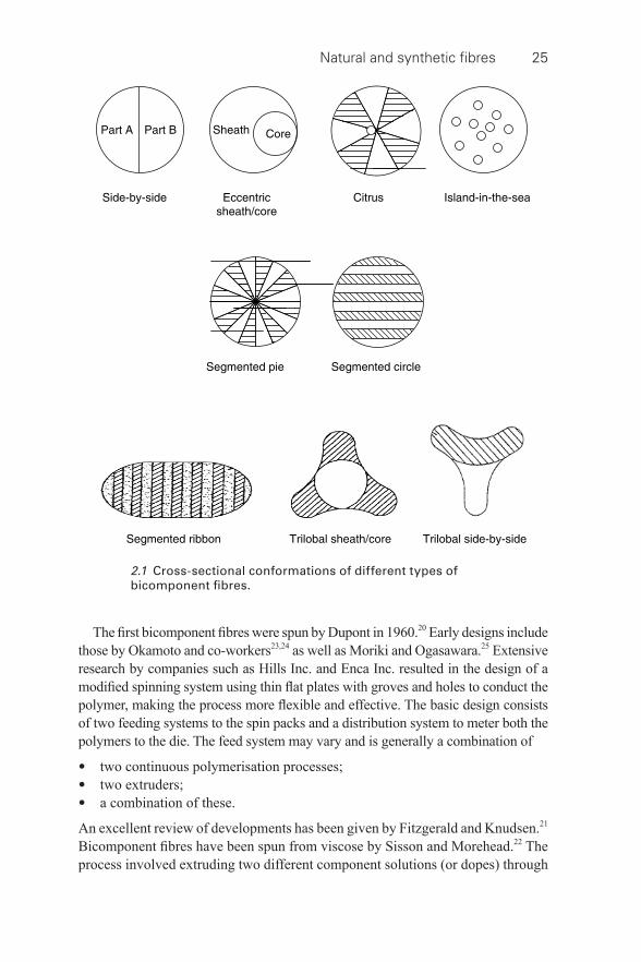
Natural and synthetic fi bres 25
The fi rst bicomponent fi bres were spun by Dupont in 1960. 20 Early designs include those by Okamoto and co- workers 23,24 as well as Moriki and Ogasawara. 25 Extensive research by companies such as Hills Inc. and Enca Inc. resulted in the design of a modifi ed spinning system using thin fl at plates with groves and holes to conduct the polymer, making the process more fl exible and effective. The basic design consists of two feeding systems to the spin packs and a distribution system to meter both the polymers to the die. The feed system may vary and is generally a combination of
• two continuous polymerisation processes; • two extruders; • a combination of these.
An excellent review of developments has been given by Fitzgerald and Knudsen. 21 Bicomponent fi bres have been spun from viscose by Sisson and Morehead. 22 The process involved extruding two different component solutions (or dopes) through
2.1 Cross- sectional conformations of different types of bicomponent fi bres.
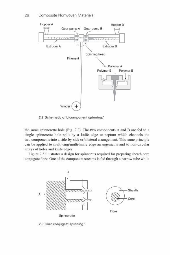
26 Composite Nonwoven Materials
the same spinnerette hole ( Fig. 2.2 ). The two components A and B are fed to a single spinnerette hole split by a knife edge or septum which channels the two components into a side- by-side or bilateral arrangement. This same principle can be applied to multi- ring/multi- knife edge arrangements and to non- circular arrays of holes and knife edges.
Figure 2.3 illustrates a design for spinnerets required for preparing sheath core conjugate fi bre. One of the component streams is fed through a narrow tube while
2.2 Schematic of bicomponent spinning. 4
2.3 Core conjugate spinning. 4
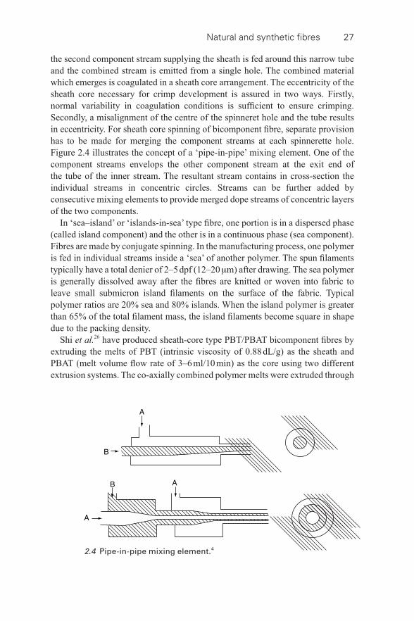
Natural and synthetic fi bres 27
the second component stream supplying the sheath is fed around this narrow tube and the combined stream is emitted from a single hole. The combined material which emerges is coagulated in a sheath core arrangement. The eccentricity of the sheath core necessary for crimp development is assured in two ways. Firstly, normal variability in coagulation conditions is suffi cient to ensure crimping. Secondly, a misalignment of the centre of the spinneret hole and the tube results in eccentricity. For sheath core spinning of bicomponent fi bre, separate provision has to be made for merging the component streams at each spinnerette hole. Figure 2.4 illustrates the concept of a ‘pipe- in-pipe’ mixing element. One of the component streams envelops the other component stream at the exit end of the tube of the inner stream. The resultant stream contains in cross- section the individual streams in concentric circles. Streams can be further added by consecutive mixing elements to provide merged dope streams of concentric layers of the two components.
In ‘sea–island’ or ‘islands- in-sea’ type fi bre, one portion is in a dispersed phase (called island component) and the other is in a continuous phase (sea component). Fibres are made by conjugate spinning. In the manufacturing process, one polymer is fed in individual streams inside a ‘sea’ of another polymer. The spun fi laments typically have a total denier of 2–5 dpf (12–20 μ m) after drawing. The sea polymer is generally dissolved away after the fi bres are knitted or woven into fabric to leave small submicron island fi laments on the surface of the fabric. Typical polymer ratios are 20% sea and 80% islands. When the island polymer is greater than 65% of the total fi lament mass, the island fi laments become square in shape due to the packing density.
Shi et al. 26 have produced sheath- core type PBT/PBAT bicomponent fi bres by extruding the melts of PBT (intrinsic viscosity of 0.88 dL/g) as the sheath and PBAT (melt volume fl ow rate of 3–6 ml/10 min) as the core using two different extrusion systems. The co- axially combined polymer melts were extruded through
2.4 Pipe-in-pipe mixing element. 4
28 Composite Nonwoven Materials
an annular- type spinneret at a temperature of 260 °C, and the mass fl ow rate was controlled at 3 g/min for each component. Compared with the respective single component fi bres, in PBT/PBAT fi bres, the molecular orientation and crystalline structure development of the PBT component was greatly enhanced, whereas the molecular orientation of the PBAT component was greatly suppressed.
The application of bicomponent fi bres has been reported in various US Patents. In one patent 27 , the manufacturing of composite elastic nonwoven fabrics was described. The composite nonwoven fabrics developed by the inventors had good strength, stretch and recovery properties. The manufacturing process involved forming a layered structure including the binder fi bre- containing fi brous web and the elastomeric net, hydroentangling the layered structure and then thermally treating the hydroentangled fabric. In a patent by Newkirk 28 , manufacturing of high loft nonwoven fabrics using bicomponent fi laments for personal hygiene products was discussed. Fabrics were composed of at least two carded webs of bicomponent thermoplastic resin fi bres. In another patent 29 , two nonwoven webs were bonded using bicomponent fi laments to create nonwoven disposable medical barrier fabrics such as surgical drapes, disposable gowns, etc. A patent by Anders et al. 30 describes a composite nonwoven material containing continuous fi laments and short fi bres in which both the continuous fi laments and short fi bres are evenly integrated into the matrix.
2.6 References
1 . G. Bhat and D. Parikh , ‘ Biodegradable materials for nonwovens ’, in R. Chapman (ed.), Applications of Nonwovens in Technical Textiles , 2010 , Woodhead Publishing Limited , Cambridge, UK .
2 . D. Robson and J. Hague , ‘ A comparison of wood and plant fi bre properties ’, in Wood Fibre Plastics Conference Proceedings , 1995 , Madison, WI , USA .
3 . Cotton Technical Guide , Cotton Incorporated , USA : http://www.cottoninc.com/Cotton-Nonwovens-Technical-Guide/ .
4 . G. Bhat , ‘ Nonwoven technology for cotton ’, in S. Gordon and Y.-L. Hsieh , Cotton: Science and Technology , 2007 , Woodhead Publishing Limited , Cambridge, UK .
5 . S. Maity , K. Singha , D. Gon , P. Paul and M. Singha , International Journal of Textile Science , Vol. 1 , Issue 5 , 2012 , pp. 36 – 43 .
6 . W. Tao , T. Calamari , F. Shih and C. Cao , TAPPI Journal , December 1997 , pp. 162 – 166 .
7 . D. Parikh , T. Calamari , A. Sawhney and E. Blanchard , Textile Research Journal , Vol. 72 , Issue 8 , 2002 , pp. 668 – 672 .
8 . D. Parikh , Y. Chen and L. Sun , Textile Research Journal , Vol. 76 , Issue 11 , 2006 , pp. 813 – 820 .
9 . G. van Roekel and E. De Jong , ‘ Elementary fl ax fi bres for disposable nonwovens ’, in TAPPI Pulping Conference Proceedings , 1999 , Orlando FL , USA .
10 . R. Anandjivala and L. Boguslasky , Textile Research Journal , Vol. 7 , Issue 7 , 2008 , pp. 616 – 617 .
11 . N. De Geyter , R. Morent and C. Leys , Surface and Coatings Technology , Vol. 201 , Issue 6 , 4 December 2006 , pp. 2460 – 2466 .
Natural and synthetic fi bres 29
12 . A. Bouazza , M. Freund and H. Nahlawi , Polymer Testing , Vol. 25 , Issue 8 , December 2006 , pp. 1038 – 1043 .
13 . H. Liu , M. Yu , B. Deng , L. Li , H. Jiang and J. Lia , Radiation Physics and Chemistry , Vol. 81 , Issue 1 , January 2012 , pp. 93 – 96 .
14 . X. Ma and D. L. Tomasko , Ind. Eng. Chem. Res. , Vol. 36 , Issue 5 , 1997 , pp. 1586 – 1597 .
15 . Y. J. Ryu , H. Y. Kim , K. H. Lee , H. C. Park and D. R. Lee , European Polymer Journal , Vol. 39 , Issue 9 , September 2003 , pp. 1883 – 1889 .
16 . R. Saraf , H. J. Lee , S. Michielsen , J. Owens , C. Willis , C. Stone and E. Wilusz , Journal of Materials Science , September 2011 , Vol. 46 , Issue 17 , pp. 5751 – 5760 .
17 . D. R. Salem , 2001 . Structure Formation in Polymeric Fibres , Hanser Verlag . 18 . http://www.hillsinc.net/bicointro.shtml [accessed 09/02/2012]. 19 . http://www.hillsinc.net/splitting.shtml [accessed 09/02/2012]. 20 . E. A. Tippets , Fiber engineering to meet end use requirements, Textile Research
Journal , Vol. 37 , Issue 6 , 1967 , 524–533. 21 . W. E. Fitzgerald and J. P. Knudsen , Mixed- stream spinning of bicomponent fi bres ,
Textile Research Journal , June 1967 , Vol. 37 , p. 447 . 22 . W. A. Sisson and F. F. Morehead , Textile Research Journal , 1953 , Vol. 23 ,
pp. 152 – 153 . 23 . M. Okamoto , K. Watanabe , Y. Nukushina , and T. Aizawa , US Pat. No. 3,531,368
(to Toyo Rayon Inc), 29 September 1970 . 24 . M. Okamoto , K. Ashida , K. Watanabe and S. Taniguchi , US Pat. No. 3,692,423
(to Toray Industries, Inc., Tokyo, Japan), 19 September 1972 . 25 . Y. O. Moriki and M. Ogasawara , Japan , US Pat. No. 4,445,833 (to Toray Industries,
Inc., Tokyo, Japan), 1 May 1984 . 26 . X. Q. Shi , H. Ito and T. Kikutani , Structure development and properties of high-
speed melt spun poly (butylene terephthalate/poly (butylene adipate- co-terephthalate) bicomponent fi bres , Polymer , 2006 , Vol. 47 , pp. 611 – 616 .
27 . J. A. Austin, T. E. Quantrille, G. S. Zimmerman, Composite elastic nonwoven fabric, US Patent 5334446, 1994.
28 . D. D. Newkirk, High loft nonwoven fabric, US Patent 4,883,707 , 1989 . 29 . J. A. Austin , M. H. S. Berman , R. A. Dunleavy , Gamma structure composite nonwoven
fabric comprising at least two nonwoven webs adhesively bonded by a lightweight adhesive web , US Patent 5,415,925 , 1995 .
30 . L. Fingal, A. Strälin, H. Ahoniemi, M. Strandqvist, A composite nonwoven material containing continuous fi laments and short fi bres, European Patent 1694895 B1.
30
© 2014 Woodhead Publishing Limited
3 Structure of composite nonwovens
D. DAS, Indian Institute of Technology Delhi, India and B. NECKÁŘ , Technical University of Liberec, Czech Republic
DOI: 10.1533/9780857097750.30
Abstract: This chapter reports on the structure of composite nonwoven materials. It fi rst describes a set of basic fi bre characteristics in homo- component nonwovens. It then develops the basic fi bre characteristics for hetero- component nonwovens. Subsequently, it depicts fi bre packing characteristics in composite nonwovens. Afterwards, it delineates fi bre directional arrangement in composite nonwovens. The chapter concludes by describing the pore structure in composite nonwovens.
Key words: composite nonwoven, structure, packing, orientation, pore.
3.1 Introduction
The basic unit of construction of a composite nonwoven structure is fi bre. Fibres are characterized by a long and thin confi guration. A large number of fi bres are organized to create the internal structure of composite nonwoven materials in a way which is infl uenced by the geometry of the fi bres used. The geometry of fi bres is generally characterized in terms of length, fi neness, diameter, aspect ratio, cross- sectional shape, surface area, specifi c surface area, etc. Understanding the geometrical characteristics of individual fi bres and their relationships in composite nonwovens consisting of homogeneous and heterogeneous fi bres is essential for understanding the structure of composite nonwovens.
The organization of fi bres in such materials is characterized by means of fi bre packing arrangement and fi bre directional arrangement. The fi bre directional arrangement is often referred to fi bre orientation. In addition, the geometry of pores is also considered to be another important structural characteristic of composite nonwoven materials.
3.2 Fibre characteristics in composite nonwovens
3.2.1 Fibre characteristics in nonwovens with homogeneous fi bre composition
Homo- component nonwovens use fi bres of the same origin and very similar characteristics. However, for the sake of simplicity, in this discussion it is assumed that all fi bres are identical. Figure 3.1 shows a fi bre that has mass m f , length l ,
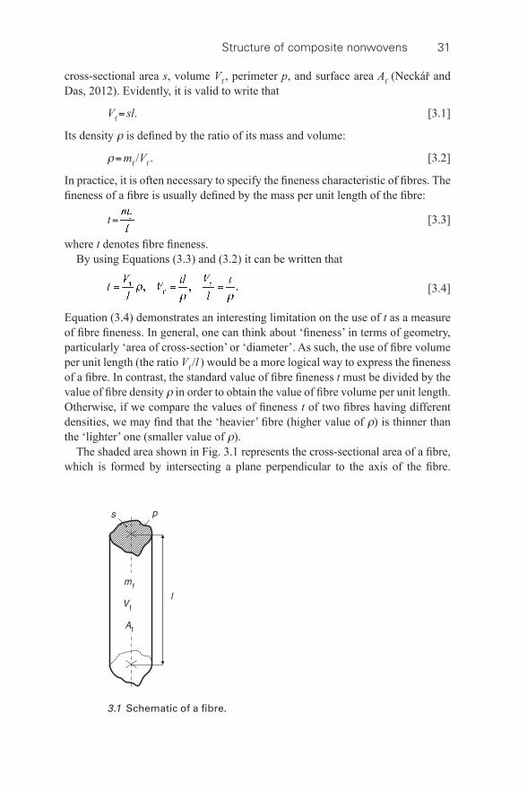
Structure of composite nonwovens 31
cross- sectional area s , volume V f , perimeter p , and surface area A f (Neckář and Das, 2012). Evidently, it is valid to write that
V f = sl . [3.1]
Its density ρ is defi ned by the ratio of its mass and volume:
ρ = m f / V f . [3.2]
In practice, it is often necessary to specify the fi neness characteristic of fi bres. The fi neness of a fi bre is usually defi ned by the mass per unit length of the fi bre:
t = [3.3]
where t denotes fi bre fi neness. By using Equations (3.3) and (3.2) it can be written that
[3.4]
Equation (3.4) demonstrates an interesting limitation on the use of t as a measure of fi bre fi neness. In general, one can think about ‘fi neness’ in terms of geometry, particularly ‘area of cross- section’ or ‘diameter’. As such, the use of fi bre volume per unit length (the ratio V f / l ) would be a more logical way to express the fi neness of a fi bre. In contrast, the standard value of fi bre fi neness t must be divided by the value of fi bre density ρ in order to obtain the value of fi bre volume per unit length. Otherwise, if we compare the values of fi neness t of two fi bres having different densities, we may fi nd that the ‘heavier’ fi bre (higher value of ρ ) is thinner than the ‘lighter’ one (smaller value of ρ ).
The shaded area shown in Fig. 3.1 represents the cross- sectional area of a fi bre, which is formed by intersecting a plane perpendicular to the axis of the fi bre.
3.1 Schematic of a fi bre.
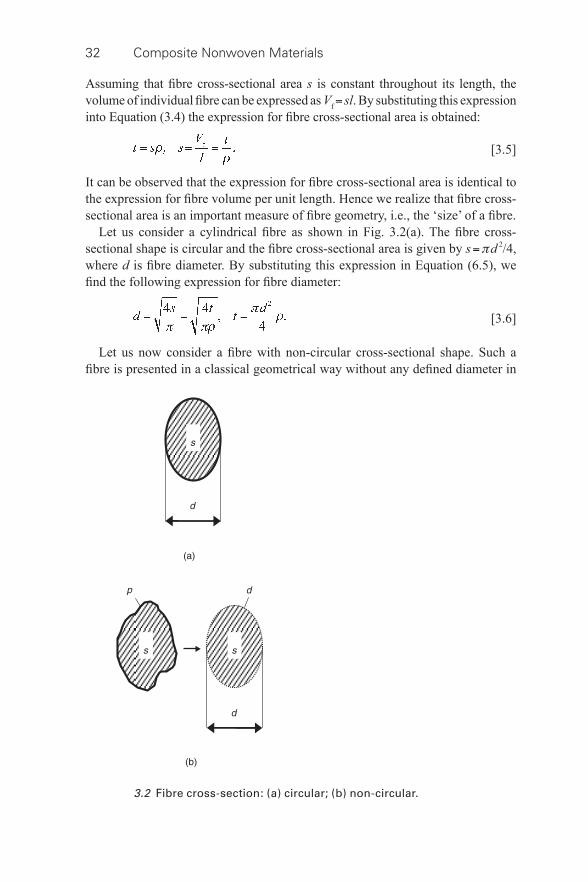
32 Composite Nonwoven Materials
Assuming that fi bre cross- sectional area s is constant throughout its length, the volume of individual fi bre can be expressed as V f = sl . By substituting this expression into Equation (3.4) the expression for fi bre cross- sectional area is obtained:
[3.5]
It can be observed that the expression for fi bre cross- sectional area is identical to the expression for fi bre volume per unit length. Hence we realize that fi bre cross- sectional area is an important measure of fi bre geometry, i.e., the ‘size’ of a fi bre.
Let us consider a cylindrical fi bre as shown in Fig. 3.2(a) . The fi bre cross- sectional shape is circular and the fi bre cross- sectional area is given by s = π d 2 /4, where d is fi bre diameter. By substituting this expression in Equation (6.5), we fi nd the following expression for fi bre diameter:
[3.6]
Let us now consider a fi bre with non- circular cross- sectional shape. Such a fi bre is presented in a classical geometrical way without any defi ned diameter in
3.2 Fibre cross- section: (a) circular; (b) non- circular.
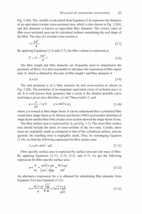
Structure of composite nonwovens 33
Fig. 3.2(b) . The variable d calculated from Equation (3.6) expresses the diameter of an equivalent circular cross- sectional area, which is also shown in Fig. 3.2(b) , and this diameter is known as equivalent fi bre diameter. The correct value of fi bre cross- sectional area can be calculated without considering the real shape of the fi bre. The area of a circular cross- section is
[3.7]
By applying Equations (3.5) and (3.7), the fi bre volume is expressed as
[3.8]
The fi bre length and fi bre diameter are frequently used to characterize the geometry of fi bres. It is then reasonable to introduce the expression of fi bre aspect ratio Λ , which is defi ned by the ratio of fi bre length l and fi bre diameter d :
Λ = l / d . [3.9]
The real perimeter p of a fi bre encloses its real cross- section as shown in Fig. 3.2(b) . The perimeter of an imaginary equivalent circle of sectional area s is π d . It is well known from geometry that a circle is the shortest possible curve enclosing a given area, therefore, p ≥ π d . Then p /( π d ) ≥ 1, and
[3.10]
where q is termed as fi bre shape factor. It can be understood that a cylindrical fi bre would show shape factor q = 0. Morton and Hearle (1962) used another defi nition of shape factor and the fi bre with circular cross- section showed the shape factor of one.
The fi bre surface area is expressed by A f = pl ( Fig. 3.1 ). The exact fi bre surface area should include the areas of cross- sections of the two ends. Usually, these areas are negligibly small as compared to that of the cylindrical surface, and are ignored; the resulting error is negligibly small. Thus, by rearranging Equation (3.10), we fi nd the following expression for fi bre surface area:
A f = pl = π d (1 + q ) l . [3.11]
Fibre specifi c surface area is expressed by surface area per unit mass of fi bre. By applying Equations (3.11), (3.3), (3.5), and (3.7), we get the following expression for fi bre specifi c surface area:
[3.12]
An alternative expression for a is obtained by substituting fi bre diameter from Equation (3.6) into Equation (3.12):
[3.13]
34 Composite Nonwoven Materials
The ratio between fi bre surface area and fi bre volume is a useful measure to characterize the geometrical structure of a fi bre. This is expressed by γ = A f / V f , where γ denotes fi bre surface area per unit volume. By applying Equations (3.11), (3.1), and (3.7) we get the following expression for fi bre surface area per unit volume:
[3.14]
By substituting Equation (3.6) into Equation (3.14), we get an alternative expression for γ :
[3.15]
By rearranging Equations (3.14) and (3.12) we can also fi nd that
γ = a ρ . [3.16]
Example 3.1 : A nonwoven material of 250 mg weight is prepared from polypropylene fi bres of 51 mm length, 6 denier fi neness, and 0.02 shape factor. The weight of one fi bre is 34 μ g. The nonwoven is composed of 7353 poly -propy-lene fi bres. The density of polypropylene fi bre is 910 kg/m 3 . The equivalent diameter of polypropylene fi bre is 30.55 μ m. The surface area of a polypropylene fi bre is 4.99 mm 2 . The total surface area occupied by all polypropylene fi bres in the nonwoven is 0.0367 m 2 . The specifi c surface area of a polypropylene fi bre is 146.76 m 2 /kg. The surface area per unit volume is 133.55 mm −1 .
3.2.2 Fibre characteristics in nonwovens with heterogeneous fi bre composition
Often fi bres of the same origin but possessing highly different characteristics or fi bres of different origins and possessing highly different properties are blended together to develop nonwoven materials. Such a fi bre blend is characterized by mean characteristic values which are expressed in terms of mean characteristic values of individual components (different types of fi bres). Then, the expressions derived in the previous section can be considered as the mean characteristic values of individual components.
Let us consider that a hetero-component nonwoven has n components, where each component consists of identical fi bres. The fi bre blend has total mass m and the mass of i -th component of the blend is m i , where i = 1, 2, . . ., n then it is valid to write that
[3.17]
Let us further consider the (mean) fi bre parameters of i- th component as density ρ i , fi neness t i , length l i , and surface area A i , specifi c surface area a i , and surface
Structure of composite nonwovens 35
area per unit volume γ i . Analogously, the characteristics of the blend will be expressed without any subscript.
The mass fraction g i of i -th fi bre component is defi ned by:
[3.18]
From Equations (3.17) and (3.18), it is valid to write that
[3.19]
In practice, the composition of a blend is usually characterized either by mass fraction (‘weight fraction’) or by mass percentage of the components. In industry, the mass fraction (mass percentage of components) is preferred, because it is relatively easy to weigh the different components of the blend.
The volume of i -th component of the blend is V i and the total volume of fi bres in the blend is V , then from the defi nition of fi bre density given by Equation (3.2) and applying Equation (3.18), we can write that
[3.20]
[3.21]
The mean fi bre density of the blend is obtained from Equations (3.2) and (3.21):
[3.22]
It is obvious from Equation (3.22) that the mean fi bre density of the blend is the weighted harmonic (not arithmetic!) mean of fi bre density of individual components of the blend. (Remember that the harmonic mean is lower than the arithmetic mean.)
The volume fraction ν i of i -th component of the blend is defi ned by the ratio between the volume of i -th component of the blend and the total volume of fi bres in the blend V . From Equations (3.20) to (3.21) we get
[3.23]
The mass fraction of the individual components of the blend g i is not a very important variable when studying the structure of the blend. This value is frequently used in industrial practice, because it is easy to determine during the blending process; on the contrary, the volume fraction υ i determines the relative

36 Composite Nonwoven Materials
space, i.e., the ‘size’ occupied by the individual component, and it is an essential characteristic for predicting the behaviour of the blend.
The total fi bre length L i of i -th component in the blend is expressed from Equations (3.3) and (3.18):
[3.24]
It is evident that the total length L of all fi bres in the blend is
[3.25]
By substituting Equation (3.25) into (3.3), we get the following expression for mean fi bre fi neness of the blend:
[3.26]
It is important to remember that the mean value of fi bre fi neness of the blend is also a weighted harmonic mean of the fi neness values of individual components of the blend.
The mean fi bre cross- sectional area s of the blend can be directly estimated from Equation (3.5) by using the mean fi bre fi neness and the mean fi bre density of the blend. This can also be found from the mean fi bre cross- sectional area of the individual components of the blend. Equation (3.5) can be used to express the fi neness of i -th component of the blend as t i = s i ρ i . Equation (3.23) can also be expressed by ν i / ρ = g i / ρ i . By substituting both equations into Equation (3.26), we get an alternative expression for the mean fi bre fi neness of the blend:
[3.27]
The mean fi bre cross- sectional area of the blend is obtained by applying Equations (3.5) and (3.27) and rearranging them:
[3.28]
As shown, the mean fi bre cross- sectional area of the blend is the weighted harmonic mean of the mean fi bre cross- sectional area of the individual components of the blend.
The mean equivalent fi bre diameter d of the blend can be directly obtained from Equation (3.6) by applying the expressions for mean fi bre fi neness and mean fi bre density of the blend. It is also possible to calculate this value from the equivalent
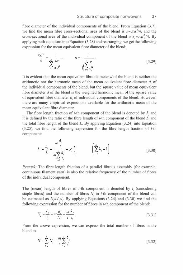
Structure of composite nonwovens 37
fi bre diameter of the individual components of the blend. From Equation (3.7), we fi nd the mean fi bre cross- sectional area of the blend is s = π d 2 /4, and the cross- sectional area of the individual component of the blend is s i = π d 2 i /4. By applying both equations into Equation (3.28) and rearranging, we get the following expression for the mean equivalent fi bre diameter of the blend:
[3.29]
It is evident that the mean equivalent fi bre diameter d of the blend is neither the arithmetic nor the harmonic mean of the mean equivalent fi bre diameter d i of the individual components of the blend, but the square value of mean equivalent fi bre diameter d of the blend is the weighted harmonic mean of the square value of equivalent fi bre diameter d i of individual components of the blend. However, there are many empirical expressions available for the arithmetic mean of the mean equivalent fi bre diameter.
The fi bre length fraction of i -th component of the blend is denoted by λ i and it is defi ned by the ratio of the fi bre length of i -th component of the blend L i and the total fi bre length of the blend L . By applying Equation (3.24) into Equation (3.25), we fi nd the following expression for the fi bre length fraction of i -th component:
[3.30]
Remark: The fi bre length fraction of a parallel fi brous assembly (for example, continuous fi lament yarn) is also the relative frequency of the number of fi bres of the individual component. The (mean) length of fi bres of i -th component is denoted by l i (considering staple fi bres) and the number of fi bres N i in i -th component of the blend can be estimated as N i = L i / l i . By applying Equations (3.24) and (3.30) we fi nd the following expression for the number of fi bres in i -th component of the blend:
[3.31]
From the above expression, we can express the total number of fi bres in the blend as
[3.32]
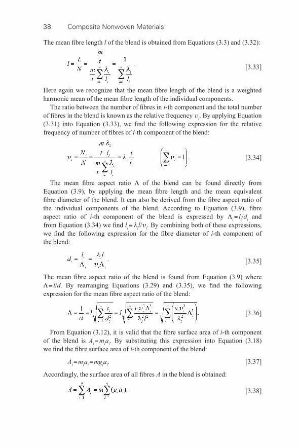
38 Composite Nonwoven Materials
The mean fi bre length l of the blend is obtained from Equations (3.3) and (3.32):
[3.33]
Here again we recognize that the mean fi bre length of the blend is a weighted harmonic mean of the mean fi bre length of the individual components.
The ratio between the number of fi bres in i -th component and the total number of fi bres in the blend is known as the relative frequency υ i . By applying Equation (3.31) into Equation (3.33), we fi nd the following expression for the relative frequency of number of fi bres of i -th component of the blend:
[3.34]
The mean fi bre aspect ratio Λ of the blend can be found directly from Equation (3.9), by applying the mean fi bre length and the mean equivalent fi bre diameter of the blend. It can also be derived from the fi bre aspect ratio of the individual components of the blend. According to Equation (3.9), fi bre aspect ratio of i -th component of the blend is expressed by Λ i = l i / d i and from Equation (3.34) we fi nd l i = λ i l / υ i . By combining both of these expressions, we fi nd the following expression for the fi bre diameter of i -th component of the blend:
[3.35]
The mean fi bre aspect ratio of the blend is found from Equation (3.9) where Λ = l / d . By rearranging Equations (3.29) and (3.35), we fi nd the following expression for the mean fi bre aspect ratio of the blend:
[3.36]
From Equation (3.12), it is valid that the fi bre surface area of i -th component of the blend is A i = m i a i . By substituting this expression into Equation (3.18) we fi nd the fi bre surface area of i -th component of the blend:
A i = m i a i = mg i a i . [3.37]
Accordingly, the surface area of all fi bres A in the blend is obtained:
[3.38]
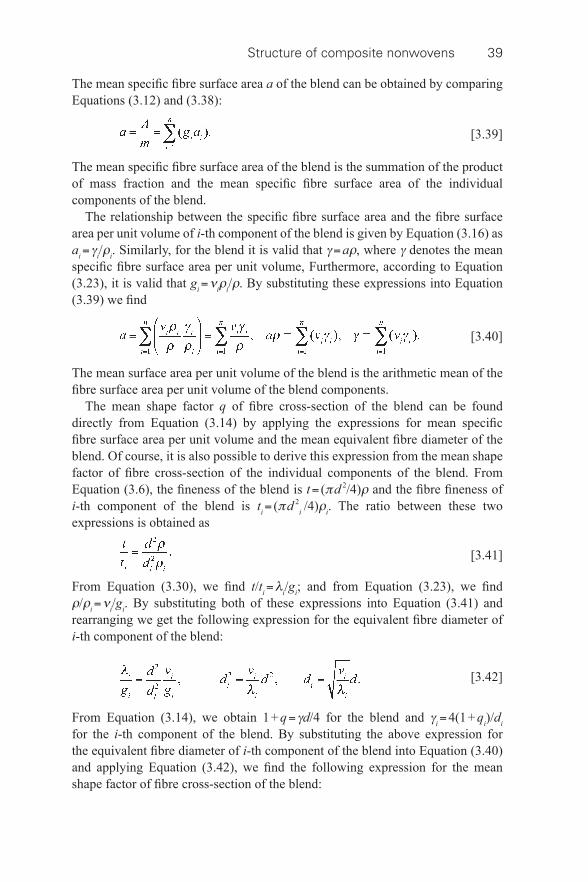
Structure of composite nonwovens 39
The mean specifi c fi bre surface area a of the blend can be obtained by comparing Equations (3.12) and (3.38):
[3.39]
The mean specifi c fi bre surface area of the blend is the summation of the product of mass fraction and the mean specifi c fi bre surface area of the individual components of the blend.
The relationship between the specifi c fi bre surface area and the fi bre surface area per unit volume of i -th component of the blend is given by Equation (3.16) as a i = γ i / ρ i . Similarly, for the blend it is valid that γ = a ρ , where γ denotes the mean specifi c fi bre surface area per unit volume, Furthermore, according to Equation (3.23), it is valid that g i = ν i ρ i / ρ . By substituting these expressions into Equation (3.39) we fi nd
[3.40]
The mean surface area per unit volume of the blend is the arithmetic mean of the fi bre surface area per unit volume of the blend components.
The mean shape factor q of fi bre cross- section of the blend can be found directly from Equation (3.14) by applying the expressions for mean specifi c fi bre surface area per unit volume and the mean equivalent fi bre diameter of the blend. Of course, it is also possible to derive this expression from the mean shape factor of fi bre cross- section of the individual components of the blend. From Equation (3.6), the fi neness of the blend is t = ( π d 2 /4) ρ and the fi bre fi neness of i -th component of the blend is t i = ( π d 2 i /4) ρ i . The ratio between these two expressions is obtained as
[3.41]
From Equation (3.30), we fi nd t / t i = λ i / g i ; and from Equation (3.23), we fi nd ρ / ρ i = ν i / g i . By substituting both of these expressions into Equation (3.41) and rearranging we get the following expression for the equivalent fi bre diameter of i -th component of the blend:
[3.42]
From Equation (3.14), we obtain 1 + q = γ d /4 for the blend and γ i = 4(1 + q i )/ d i for the i -th component of the blend. By substituting the above expression for the equivalent fi bre diameter of i -th component of the blend into Equation (3.40) and applying Equation (3.42), we fi nd the following expression for the mean shape factor of fi bre cross- section of the blend:
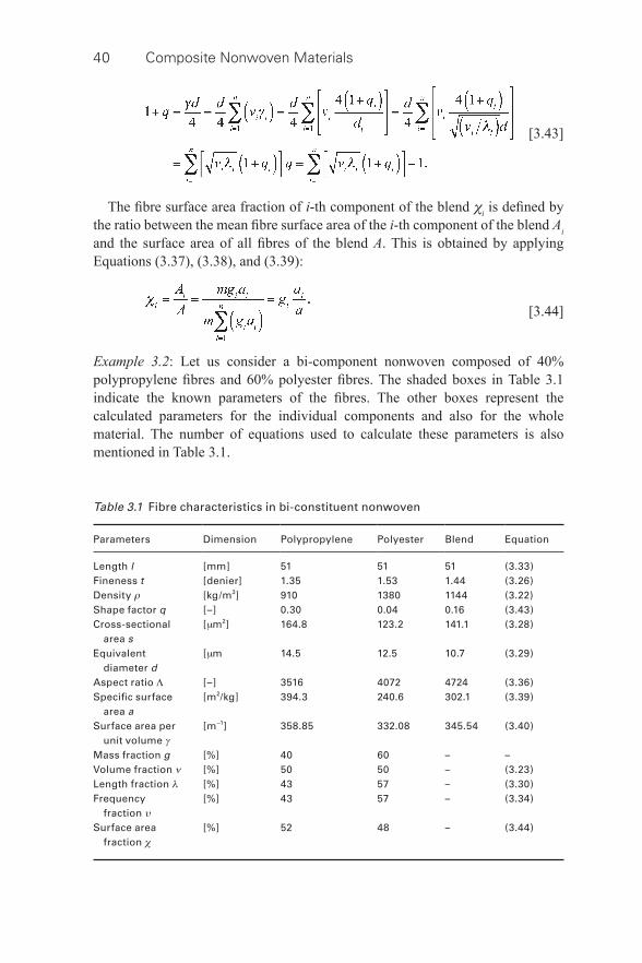
40 Composite Nonwoven Materials
[3.43]
The fi bre surface area fraction of i -th component of the blend χ i is defi ned by the ratio between the mean fi bre surface area of the i -th component of the blend A i and the surface area of all fi bres of the blend A . This is obtained by applying Equations (3.37), (3.38), and (3.39):
[3.44]
Example 3.2 : Let us consider a bi- component nonwoven composed of 40% polypropylene fi bres and 60% polyester fi bres. The shaded boxes in Table 3.1 indicate the known parameters of the fi bres. The other boxes represent the calculated parameters for the individual components and also for the whole material. The number of equations used to calculate these parameters is also mentioned in Table 3.1 .
Table 3.1 Fibre characteristics in bi- constituent nonwoven
Parameters Dimension Polypropylene Polyester Blend Equation
Length l [mm] 51 51 51 (3.33) Fineness t [denier] 1.35 1.53 1.44 (3.26) Density ρ [kg/m 3 ] 910 1380 1144 (3.22) Shape factor q [–] 0.30 0.04 0.16 (3.43) Cross- sectional area s
[ μ m 2 ] 164.8 123.2 141.1 (3.28)
Equivalent diameter d
[ μ m 14.5 12.5 10.7 (3.29)
Aspect ratio Λ [–] 3516 4072 4724 (3.36) Specifi c surface area a
[m 2 /kg] 394.3 240.6 302.1 (3.39)
Surface area per unit volume γ
[m −1 ] 358.85 332.08 345.54 (3.40)
Mass fraction g [%] 40 60 – – Volume fraction ν [%] 50 50 – (3.23) Length fraction λ [%] 43 57 – (3.30) Frequency fraction υ
[%] 43 57 – (3.34)
Surface area fraction χ
[%] 52 48 – (3.44)
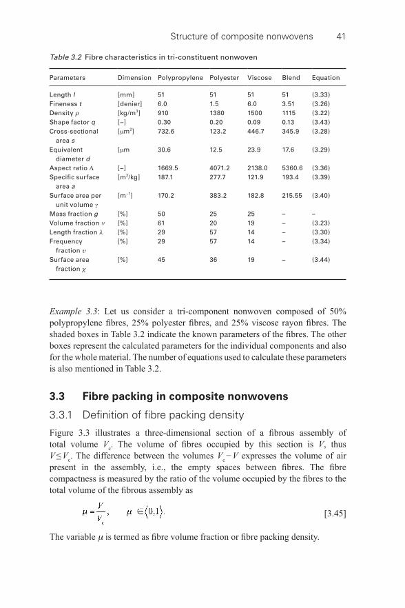
Structure of composite nonwovens 41
Example 3.3 : Let us consider a tri- component nonwoven composed of 50% polypropylene fi bres, 25% polyester fi bres, and 25% viscose rayon fi bres. The shaded boxes in Table 3.2 indicate the known parameters of the fi bres. The other boxes represent the calculated parameters for the individual components and also for the whole material. The number of equations used to calculate these parameters is also mentioned in Table 3.2 .
3.3 Fibre packing in composite nonwovens
3.3.1 Defi nition of fi bre packing density
Figure 3.3 illustrates a three- dimensional section of a fi brous assembly of total volume V c . The volume of fi bres occupied by this section is V , thus V ≤ V c . The difference between the volumes V c − V expresses the volume of air present in the assembly, i.e., the empty spaces between fi bres. The fi bre compactness is measured by the ratio of the volume occupied by the fi bres to the total volume of the fi brous assembly as
[3.45]
The variable μ is termed as fi bre volume fraction or fi bre packing density.
Table 3.2 Fibre characteristics in tri- constituent nonwoven
Parameters Dimension Polypropylene Polyester Viscose Blend Equation
Length l [mm] 51 51 51 51 (3.33) Fineness t [denier] 6.0 1.5 6.0 3.51 (3.26) Density ρ [kg/m 3 ] 910 1380 1500 1115 (3.22) Shape factor q [–] 0.30 0.20 0.09 0.13 (3.43) Cross- sectional area s
[ μ m 2 ] 732.6 123.2 446.7 345.9 (3.28)
Equivalent diameter d
[ μ m 30.6 12.5 23.9 17.6 (3.29)
Aspect ratio Λ [–] 1669.5 4071.2 2138.0 5360.6 (3.36) Specifi c surface area a
[m 2 /kg] 187.1 277.7 121.9 193.4 (3.39)
Surface area per unit volume γ
[m −1 ] 170.2 383.2 182.8 215.55 (3.40)
Mass fraction g [%] 50 25 25 – – Volume fraction ν [%] 61 20 19 – (3.23) Length fraction λ [%] 29 57 14 – (3.30) Frequency fraction υ
[%] 29 57 14 – (3.34)
Surface area fraction χ
[%] 45 36 19 – (3.44)
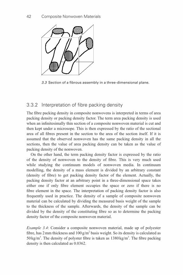
42 Composite Nonwoven Materials
3.3.2 Interpretation of fi bre packing density
The fi bre packing density in composite nonwovens is interpreted in terms of area packing density or packing density factor. The term area packing density is used when an infi nitesimally thin section of a composite nonwoven material is cut and then kept under a microsope. This is then expressed by the ratio of the sectional area of all fi bres present in the section to the area of the section itself. If it is assumed that the observed nonwoven has the same packing density in all the sections, then the value of area packing density can be taken as the value of packing density of the nonwoven.
On the other hand, the term packing density factor is expressed by the ratio of the density of nonwoven to the density of fi bre. This is very much used while studying the continuum models of nonwoven media. In continuum modelling, the density of a mass element is divided by an arbitrary constant (density of fi bre) to get packing density factor of the element. Actually, the packing density factor at an arbitrary point in a three- dimensional space takes either one if only fi bre element occupies the space or zero if there is no fi bre element in the space. The interpretation of packing density factor is also frequently used in practice. The density of a sample of composite nonwoven material can be calculated by dividing the measured basis weight of the sample to the thickness of the sample. Afterwards, the density of the sample can be divided by the density of the constituting fi bre so as to determine the packing density factor of the composite nonwoven material. Example 3.4 : Consider a composite nonwoven material, made up of polyester fi bre, has 2 mm thickness and 100 g/m 2 basis weight. So its density is calculated as 50 kg/m 3 . The density of polyster fi bre is taken as 1380 kg/m 3 . The fi bre packing density is then calculated as 0.0362.
3.3 Section of a fi brous assembly in a three- dimensional plane.
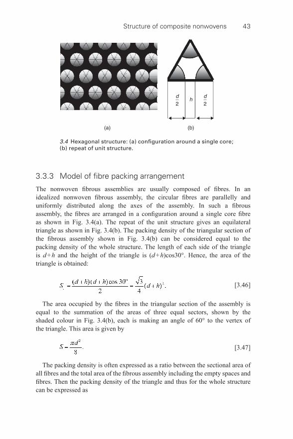
Structure of composite nonwovens 43
3.3.3 Model of fi bre packing arrangement
The nonwoven fi brous assemblies are usually composed of fi bres. In an idealized nonwoven fi brous assembly, the circular fi bres are parallelly and uniformly distributed along the axes of the assembly. In such a fi brous assembly, the fi bres are arranged in a confi guration around a single core fi bre as shown in Fig. 3.4(a) . The repeat of the unit structure gives an equilateral triangle as shown in Fig. 3.4(b) . The packing density of the triangular section of the fi brous assembly shown in Fig. 3.4(b) can be considered equal to the packing density of the whole structure. The length of each side of the triangle is d + h and the height of the triangle is ( d + h )cos30°. Hence, the area of the triangle is obtained:
[3.46]
The area occupied by the fi bres in the triangular section of the assembly is equal to the summation of the areas of three equal sectors, shown by the shaded colour in Fig. 3.4(b) , each is making an angle of 60° to the vertex of the triangle. This area is given by
[3.47]
The packing density is often expressed as a ratio between the sectional area of all fi bres and the total area of the fi brous assembly including the empty spaces and fi bres. Then the packing density of the triangle and thus for the whole structure can be expressed as
3.4 Hexagonal structure: (a) confi guration around a single core; (b) repeat of unit structure.
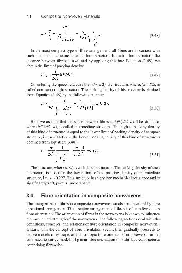
44 Composite Nonwoven Materials
[3.48]
In the most compact type of fi bre arrangement, all fi bres are in contact with each other. This structure is called limit structure. In such a limit structure, the distance between fi bres is h = 0 and by applying this into Equation (3.48), we obtain the limit of packing density:
[3.49]
Considering the space between fi bres ( h < d /2), the structure, where, ( h < d /2), is called compact or tight structure. The packing density of this structure is obtained from Equation (3.48) by the following manner:
[3.50]
Here we assume that the space between fi bres is h ∈ 〈 d /2, d 〉. The structure, where h ∈ 〈 d /2, d 〉, is called intermediate structure. The highest packing density of this kind of structure is equal to the lower limit of packing density of compact structure, i.e., μ ≅ 0.403 and the lowest packing density of this kind of structure is obtained from Equation (3.48):
[3.51]
The structure, where h > d , is called loose structure. The packing density of such a structure is less than the lower limit of the packing density of intermediate structure, i.e., μ < 0.227. This structure has very low mechanical resistance and is signifi cantly soft, porous, and drapable.
3.4 Fibre orientation in composite nonwovens
The arrangement of fi bres in composite nonwovens can also be described by fi bre directional arrangement. The direction arrangement of fi bres is often referred to as fi bre orientation. The orientation of fi bres in the nonwovens is known to infl uence the mechanical strength of the nonwovens. The following sections deal with the defi nitions, concepts, and relations of fi bre orientation in composite nonwovens. It starts with the concept of fi bre orientation vector, then gradually proceeds to derive models of isotropic and anisotropic fi bre orientation in fi brewebs, further continued to derive models of planar fi bre orientation in multi- layered structures comprising fi brewebs.
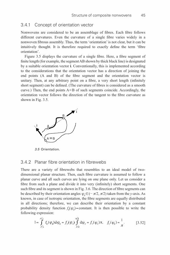
Structure of composite nonwovens 45
3.4.1 Concept of orientation vector
Nonwovens are considered to be an assemblage of fi bres. Each fi bre follows different curvatures. Even the curvature of a single fi bre varies widely in a nonwoven fi brous assembly. Thus, the term ‘orientation’ is not clear, but it can be intuitively thought. It is therefore required to exactly defi ne the term ‘fi bre orientation’.
Figure 3.5 displays the curvature of a single fi bre. Here, a fi bre segment of fi nite length (for example, the segment AB shown by thick black line) is designated by a suitable orientation vector i . Conventionally, this is implemented according to the considerations that the orientation vector has a direction of joining the end points (A and B) of the fi bre segment and the orientation vector is unitary. Then, at any arbitrary point on a fi bre, a very short length (infi nitely short segment) can be defi ned. (The curvature of fi bres is considered as a smooth curve.) Then, the end points A ≡ B of such segments coincide. Accordingly, the orientation vector follows the direction of the tangent to the fi bre curvature as shown in Fig. 3.5 .
3.5 Orientation.
3.4.2 Planar fi bre orientation in fi brewebs
There are a variety of fi brewebs that resembles to an ideal model of two- dimensional planar structure. Then, each fi bre curvature is assumed to follow a planar curve and all such curves are lying on one plane only. Let us consider a fi bre from such a plane and divide it into very (infi nitely) short segments. One such fi bre and its segment is shown in Fig. 3.6 . The direction of fi bre segments can be described by their orientation angles ψ 0 ∈ (− π /2, π /2) taken from the y -axis. As known, in case of isotropic orientation, the fi bre segments are equally distributed in all directions; therefore, we can describe their orientation by a constant probability density function f 0 ( ψ 0 ) = constant. It is then possible to write the following expression:
[3.52]
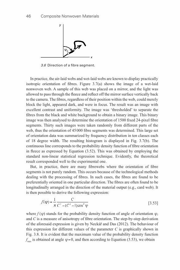
46 Composite Nonwoven Materials
In practice, the air- laid webs and wet- laid webs are known to display practically isotropic orientation of fi bres. Figure 3.7(a) shows the image of a wet- laid nonwoven web. A sample of this web was placed on a mirror, and the light was allowed to pass through the fl eece and refl ect off the mirror surface vertically back to the camera. The fi bres, regardless of their position within the web, could merely block the light, appeared dark, and were in focus. The result was an image with excellent contrast and uniformity. The image was ‘thresholded’ to separate the fi bres from the black and white background to obtain a binary image. This binary image was then analysed to determine the orientation of 1500 fi xed 24-pixel fi bre segments. Thirty such images were taken randomly from different parts of the web, thus the orientation of 45 000 fi bre segments was determined. This large set of orientation data was summarized by frequency distribution in ten classes each of 18 degree width. The resulting histogram is displayed in Fig. 3.7(b) . The continuous line corresponds to the probability density function of fi bre orientation in fl eece as expressed by Equation (3.52). This was obtained by employing the standard non- linear statistical regression technique. Evidently, the theoretical result corresponded well to the experimental one.
But, in practice, there are many fi brewebs where the orientation of fi bre segments is not purely random. This occurs because of the technological methods dealing with the processing of fi bres. In such cases, the fi bres are found to be preferentially oriented in one particular direction. The fi bres are often found to be longitudinally arranged in the direction of the material output (e.g., card web). It is then possible to derive the following expression:
[3.53]
where f ( ψ ) stands for the probability density function of angle of orientation ψ , and C is a measure of anisotropy of fi bre orientation. The step- by-step derivation of the aforesaid expression is given by Neckář and Das (2012). The behaviour of this expression for different values of the parameter C is graphically shown in Fig. 3.8 . It is evident that the maximum value of the probability density function f max is obtained at angle ψ = 0, and then according to Equation (3.53), we obtain
3.6 Direction of a fi bre segment.
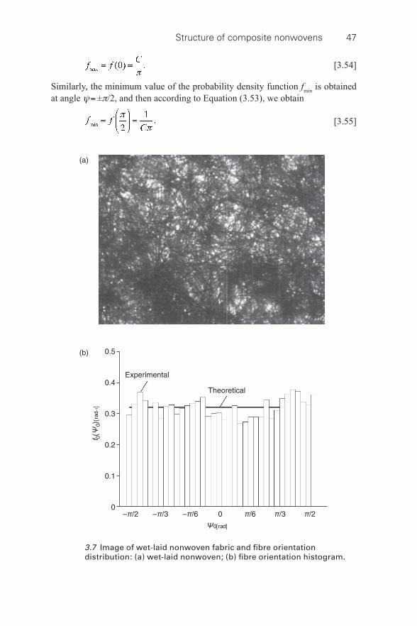
Structure of composite nonwovens 47
[3.54]
Similarly, the minimum value of the probability density function f min is obtained at angle ψ = ± π /2, and then according to Equation (3.53), we obtain
[3.55]
3.7 Image of wet- laid nonwoven fabric and fi bre orientation distribution: (a) wet- laid nonwoven; (b) fi bre orientation histogram.
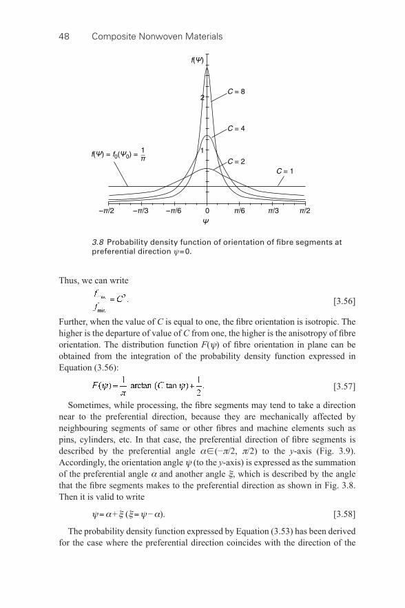
48 Composite Nonwoven Materials
Thus, we can write
[3.56]
Further, when the value of C is equal to one, the fi bre orientation is isotropic. The higher is the departure of value of C from one, the higher is the anisotropy of fi bre orientation. The distribution function F ( ψ ) of fi bre orientation in plane can be obtained from the integration of the probability density function expressed in Equation (3.56):
[3.57]
Sometimes, while processing, the fi bre segments may tend to take a direction near to the preferential direction, because they are mechanically affected by neighbouring segments of same or other fi bres and machine elements such as pins, cylinders, etc. In that case, the preferential direction of fi bre segments is described by the preferential angle α ∈ (− π /2, π /2) to the y -axis ( Fig. 3.9 ). Accordingly, the orientation angle ψ (to the y -axis) is expressed as the summation of the preferential angle α and another angle ξ , which is described by the angle that the fi bre segments makes to the preferential direction as shown in Fig. 3.8 . Then it is valid to write
ψ = α + ξ ( ξ = ψ − α ). [3.58]
The probability density function expressed by Equation (3.53) has been derived for the case where the preferential direction coincides with the direction of the
3.8 Probability density function of orientation of fi bre segments at preferential direction ψ = 0.
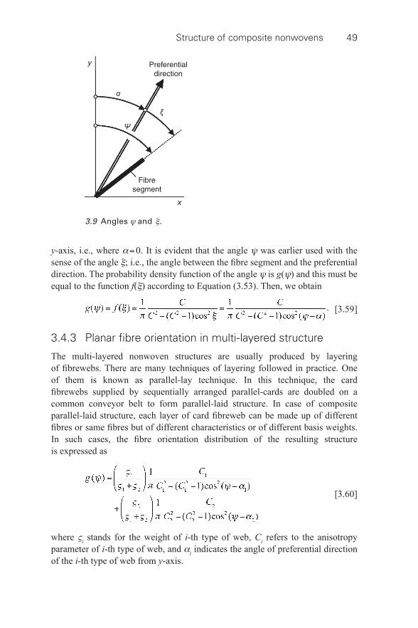
Structure of composite nonwovens 49
y -axis, i.e., where α = 0. It is evident that the angle ψ was earlier used with the sense of the angle ξ ; i.e., the angle between the fi bre segment and the preferential direction. The probability density function of the angle ψ is g ( ψ ) and this must be equal to the function f ( ξ ) according to Equation (3.53). Then, we obtain
[3.59]
3.4.3 Planar fi bre orientation in multi- layered structure
The multi- layered nonwoven structures are usually produced by layering of fi brewebs. There are many techniques of layering followed in practice. One of them is known as parallel- lay technique. In this technique, the card fi brewebs supplied by sequentially arranged parallel- cards are doubled on a common conveyor belt to form parallel- laid structure. In case of composite parallel- laid structure, each layer of card fi breweb can be made up of different fi bres or same fi bres but of different characteristics or of different basis weights. In such cases, the fi bre orientation distribution of the resulting structure is expressed as
[3.60]
where ς i stands for the weight of i -th type of web, C i refers to the anisotropy parameter of i -th type of web, and α i indicates the angle of preferential direction of the i -th type of web from y -axis.
3.9 Angles ψ and ξ .
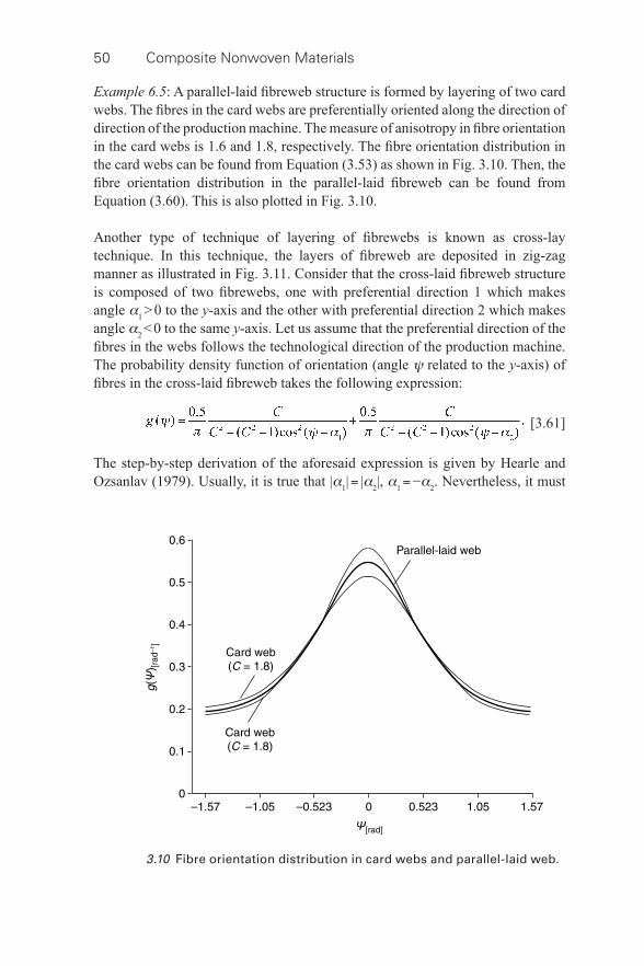
50 Composite Nonwoven Materials
Example 6.5 : A parallel- laid fi breweb structure is formed by layering of two card webs. The fi bres in the card webs are preferentially oriented along the direction of direction of the production machine. The measure of anisotropy in fi bre orientation in the card webs is 1.6 and 1.8, respectively. The fi bre orientation distribution in the card webs can be found from Equation (3.53) as shown in Fig. 3.10 . Then, the fi bre orientation distribution in the parallel- laid fi breweb can be found from Equation (3.60). This is also plotted in Fig. 3.10 .
Another type of technique of layering of fi brewebs is known as cross- lay technique. In this technique, the layers of fi breweb are deposited in zig- zag manner as illustrated in Fig. 3.11 . Consider that the cross- laid fi breweb structure is composed of two fi brewebs, one with preferential direction 1 which makes angle α 1 > 0 to the y -axis and the other with preferential direction 2 which makes angle α 2 < 0 to the same y -axis. Let us assume that the preferential direction of the fi bres in the webs follows the technological direction of the production machine. The probability density function of orientation (angle ψ related to the y -axis) of fi bres in the cross- laid fi breweb takes the following expression:
[3.61]
The step- by-step derivation of the aforesaid expression is given by Hearle and Ozsanlav (1979). Usually, it is true that | α 1 | = | α 2 |, α 1 = − α 2 . Nevertheless, it must
3.10 Fibre orientation distribution in card webs and parallel- laid web.
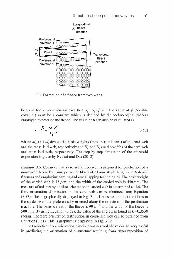
Structure of composite nonwovens 51
be valid for a more general case that α 1 − α 2 = β and the value of β (‘double α -value’) must be a constant which is decided by the technological process employed to produce the fl eece. The value of β can also be calculated as
[3.62]
where M w and M f denote the basis weights (mass per unit area) of the card web and the cross- laid web, respectively and H w and H f are the widths of the card web and cross- laid web, respectively. The step- by-step derivation of the aforesaid expression is given by Neckář and Das (2012). Example 3.6 : Consider that a cross- laid fi breweb is prepared for production of a nonwoven fabric by using polyester fi bres of 51 mm staple length and 6 denier fi neness and employing carding and cross- lapping technologies. The basis weight of the carded web is 18 g/m 2 and the width of the carded web is 440 mm. The measure of anisotropy of fi bre orientation in carded web is determined as 1.6. The fi bre orientation distribution in the card web can be obtained from Equation (3.53). This is graphically displayed in Fig. 3.11 . Let us assume that the fi bres in the carded web are preferentially oriented along the direction of the production machine. The basis weight of the fl eece is 90 g/m 2 and the width of the fl eece is 500 mm. By using Equation (3.62), the value of the angle β is found as β = 0.3538 radian. The fi bre orientation distribution in cross- laid web can be obtained from Equation (3.61). This is graphically displayed in Fig. 3.12 .
The theoretical fi bre orientation distributions derived above can be very useful in predicting the orientation of a structure resulting from superimposition of
3.11 Formation of a fl eece from two webs.
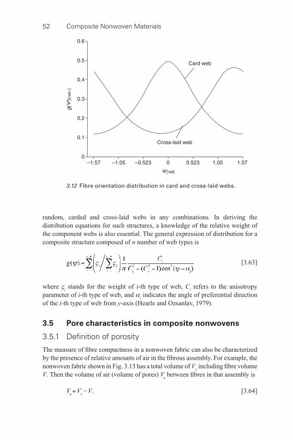
52 Composite Nonwoven Materials
random, carded and cross- laid webs in any combinations. In deriving the distribution equations for such structures, a knowledge of the relative weight of the component webs is also essential. The general expression of distribution for a composite structure composed of n number of web types is
[3.63]
where ς i stands for the weight of i -th type of web, C i refers to the anisotropy parameter of i -th type of web, and α i indicates the angle of preferential direction of the i -th type of web from y -axis (Hearle and Ozsanlav, 1979).
3.5 Pore characteristics in composite nonwovens
3.5.1 Defi nition of porosity
The measure of fi bre compactness in a nonwoven fabric can also be characterized by the presence of relative amounts of air in the fi brous assembly. For example, the nonwoven fabric shown in Fig. 3.13 has a total volume of V c including fi bre volume V . Then the volume of air (volume of pores) V a between fi bres in that assembly is
V a = V c − V . [3.64]
3.12 Fibre orientation distribution in card and cross- laid webs.

Structure of composite nonwovens 53
The relative volume of air is expressed by porosity ζ = V a / V c . By applying Equations (3.64) and (3.45) into the expression of porosity, we fi nd the following expression:
[3.65]
3.5.2 Interpretation of pores
Nonwovens are known to be fi brous porous material. A large volume of this material is occupied by air and the rest is occupied by fi bres. If this material is projected onto a two- dimensional plane, an ‘elementary plane’ of this material is obtained. This is shown in Fig. 3.12 . Evidently, this plane consists of many fi bres and numerous air spaces surrounding the fi bres. Let us call these air spaces ‘pores’. One such pore is shown in Fig. 3.13 .
3.5.3 Model of pore geometry
Simmonds et al. (2007) reported a model of pore structure in an elementary plane of a nonwoven fabric. As per this model, let the fi bres be distributed randomly in an elementary plane of unit area and the probability P ( n f ) that any given point is covered by n f fi bres present per unit area of the plane is given by Poisson distribution of the following form:
[3.66]
3.13 Image of a Pore.

54 Composite Nonwoven Materials
where c is the total projected area of fi bres per unit area of the plane. Often, c is termed as coverage and it is expressed as c = n f ld , where l is fi bre length, and d is fi bre width (diameter). According to the geometrical defi nition of probability, P ( n f ) is the area covered by n fi bres per unit area of the plane, that is, P ( n f ) is the fraction of unit area covered by n fi bres. If so then P (0) is the fraction of unit area not covered by fi bres, then P (0) represents the open area fraction of the plane. Then, P (0) = e −c . Clearly, 1 − e −c is the fraction of the unit area covered by fi bres. Similarly, P (1) is the fraction of area covered by one fi bre, P (2) is the fraction of area covered by two fi bres, and so on. Let us assume that a point covered by n f fi bres is covered by n f − 1 crossings. Then, the total area A c occupied by all fi bre crossings per unit area of the plane can be derived by using Equation (3.66):
[3.67]
Thus, the total area of fi bre crossings A c is the difference between the total coverage c and the fraction of the unit area covered by fi bres (1 − e −c ). The area a c occupied by one fi bre crossing is given by
[3.68]
Then, for a small value of c , the number n c of fi bre crossings per unit area of the plane can be obtained by using Equations (3.67) and (3.68):
[3.69]
The fi bre- to-fi bre crossings create the vertices of polygons in the plane. Each polygon simulates a pore. According to Kallmes and Corte (1960), the expression for a number of such pores n p is
n p = ( n c − n f ) e −c . [3.70]
Using the above expression, the mean cross- sectional area a p of a pore is obtained:
[3.71]
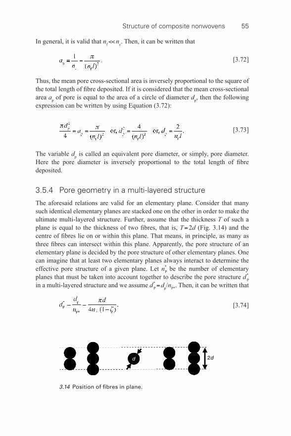
Structure of composite nonwovens 55
In general, it is valid that n f << n c . Then, it can be written that
[3.72]
Thus, the mean pore cross- sectional area is inversely proportional to the square of the total length of fi bre deposited. If it is considered that the mean cross- sectional area a p of pore is equal to the area of a circle of diameter d p , then the following expression can be written by using Equation (3.72):
[3.73]
The variable d p is called an equivalent pore diameter, or simply, pore diameter. Here the pore diameter is inversely proportional to the total length of fi bre deposited.
3.5.4 Pore geometry in a multi- layered structure
The aforesaid relations are valid for an elementary plane. Consider that many such identical elementary planes are stacked one on the other in order to make the ultimate multi- layered structure. Further, assume that the thickness T of such a plane is equal to the thickness of two fi bres, that is, T = 2 d ( Fig. 3.14 ) and the centre of fi bres lie on or within this plane. That means, in principle, as many as three fi bres can intersect within this plane. Apparently, the pore structure of an elementary plane is decided by the pore structure of other elementary planes. One can imagine that at least two elementary planes always interact to determine the effective pore structure of a given plane. Let n * P be the number of elementary planes that must be taken into account together to describe the pore structure d * P in a multi- layered structure and we assume d * P = d p / n P *. Then, it can be written that
[3.74]
3.14 Position of fi bres in plane.
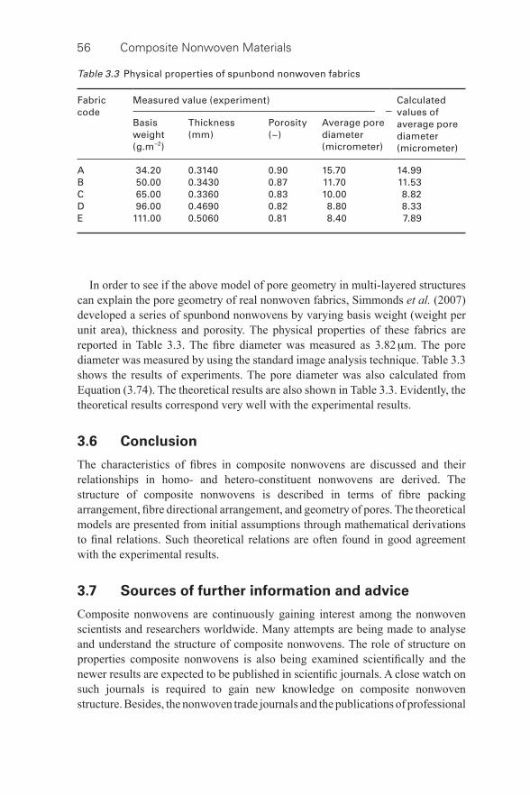
56 Composite Nonwoven Materials
Table 3.3 Physical properties of spunbond nonwoven fabrics
Fabric code
Measured value (experiment) Calculated values of average pore diameter (micrometer)
Basis weight (g.m −2 )
Thickness (mm)
Porosity (−)
Average pore diameter (micrometer)
A 34.20 0.3140 0.90 15.70 14.99 B 50.00 0.3430 0.87 11.70 11.53 C 65.00 0.3360 0.83 10.00 8.82 D 96.00 0.4690 0.82 8.80 8.33 E 111.00 0.5060 0.81 8.40 7.89
In order to see if the above model of pore geometry in multi- layered structures can explain the pore geometry of real nonwoven fabrics, Simmonds et al. (2007) developed a series of spunbond nonwovens by varying basis weight (weight per unit area), thickness and porosity. The physical properties of these fabrics are reported in Table 3.3 . The fi bre diameter was measured as 3.82 μ m. The pore diameter was measured by using the standard image analysis technique. Table 3.3 shows the results of experiments. The pore diameter was also calculated from Equation (3.74). The theoretical results are also shown in Table 3.3 . Evidently, the theoretical results correspond very well with the experimental results.
3.6 Conclusion
The characteristics of fi bres in composite nonwovens are discussed and their relationships in homo- and hetero- constituent nonwovens are derived. The structure of composite nonwovens is described in terms of fi bre packing arrangement, fi bre directional arrangement, and geometry of pores. The theoretical models are presented from initial assumptions through mathematical derivations to fi nal relations. Such theoretical relations are often found in good agreement with the experimental results.
3.7 Sources of further information and advice
Composite nonwovens are continuously gaining interest among the nonwoven scientists and researchers worldwide. Many attempts are being made to analyse and understand the structure of composite nonwovens. The role of structure on properties composite nonwovens is also being examined scientifi cally and the newer results are expected to be published in scientifi c journals. A close watch on such journals is required to gain new knowledge on composite nonwoven structure. Besides, the nonwoven trade journals and the publications of professional
Structure of composite nonwovens 57
bodies such as INDA and EDANA can also be looked at to obtain newer information on the structures of composite nonwovens.
3.8 References
Hearle , J. W. S. and Ozsanlav , V. ( 1979 ), Studies of adhesive- bonded non- woven fabrics Part III: The determination of fi bre orientation and curl , Journal of Textile Institute , 11 , 487 – 498 .
Kallmes , O. and Corte , H. ( 1960 ), The structure of paper: 1. The statistical geometry of an ideal two- dimensional fi bre network , TAPPI , 43 ( 9 ), 737 – 752 .
Morton , W. E. and Hearle , J. W. S. ( 1962 ), Physical Properties of Textile Fibres , The Textile Institute and Butterworth and Co. , London .
Neckář , B. and Das , D. ( 2012 ), Theory of Structure and Mechanics of Fibrous Assemblies , Woodhead Publishing India Pvt. Ltd. , New Delhi .
Simmonds , G. E. , Bomberger , J. D. and Bryner , M. A. ( 2007 ), Designing nonwovens to meet pore size specifi cations , Journal of Engineered Fibres and Fabrics , 2 ( 1 ), 1 – 15 .
58
© 2014 Woodhead Publishing Limited
4 Properties of composite nonwovens
D. DAS, Indian Institute of Technology Delhi, India
DOI: 10.1533/9780857097750.58
Abstract: This chapter reports on the physical properties of composite nonwoven materials. These properties include strength and elongation, fl uid permeability, thermal conductivity, liquid sorption, and particle fi ltration. The chapter summarizes the research progress made so far in establishing the roles of fi bre materials and process technologies in determining these properties. Special attention is paid to the structure–property relationship in composite nonwoven materials.
Key words: composite nonwoven, strength, permeability, absorption, fi ltration.
4.1 Introduction
Composite nonwovens are considered to be advanced technical textiles. They are manufactured by combining different fi bres and fi laments as well as various substrates and structures using a range of process technologies. They are often characterized in terms of their physical properties including tensile strength, breaking elongation, bursting strength, fl uid permeability, thermal conductivity, liquid sorption, and particle fi ltration. These properties are primarily determined by fi bre characteristics, technological parameters, and structural features.
Understanding material–process–structure–property relationships has always been an important topic of research in composite nonwovens. This relationship is complicated due to the complex variables arising from the raw materials and the process technologies used. In spite of this, an in- depth knowledge has been gained over the years on material–process structure–property relationships in composite nonwovens. This knowledge is used by product development engineers to create novel or improved composite nonwoven products for a variety of applications.
4.2 Mechanical properties of composite nonwovens
One of the reasons for the development of composite nonwovens is related to the higher strength and other functionalities that can be achieved. Take the case of the spunbond- meltblown-spunbond (SMS) composite nonwoven, where the meltblown nonwoven imparts liquid and particulate barrier properties, whilst the spunbond nonwoven provides strength and abrasion resistance (Russel, 2007). As with any other manufactured material, the mechanical properties of composite nonwovens are primarily determined by the characteristics of the constituent
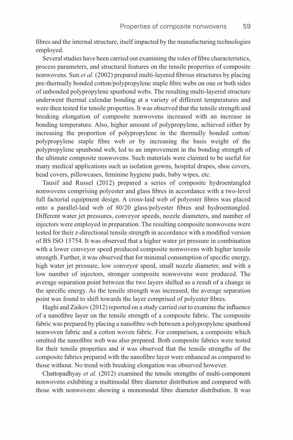
Properties of composite nonwovens 59
fi bres and the internal structure, itself impacted by the manufacturing technologies employed.
Several studies have been carried out examining the roles of fi bre characteristics, process parameters, and structural features on the tensile properties of composite nonwovens. Sun et al. (2002) prepared multi- layered fi brous structures by placing pre- thermally bonded cotton/polypropylene staple fi bre webs on one or both sides of unbonded polypropylene spunbond webs. The resulting multi- layered structure underwent thermal calendar bonding at a variety of different temperatures and were then tested for tensile properties. It was observed that the tensile strength and breaking elongation of composite nonwovens increased with an increase in bonding temperature. Also, higher amount of polypropylene, achieved either by increasing the proportion of polypropylene in the thermally bonded cotton/polypropylene staple fi bre web or by increasing the basis weight of the polypropylene spunbond web, led to an improvement in the bonding strength of the ultimate composite nonwovens. Such materials were claimed to be useful for many medical applications such as isolation gowns, hospital drapes, shoe covers, head covers, pillowcases, feminine hygiene pads, baby wipes, etc.
Tausif and Russel (2012) prepared a series of composite hydroentangled nonwovens comprising polyester and glass fi bres in accordance with a two- level full factorial equipment design. A cross- laid web of polyester fi bres was placed onto a parallel- laid web of 80/20 glass/polyester fi bres and hydroentangled. Different water jet pressures, conveyor speeds, nozzle diameters, and number of injectors were employed in preparation. The resulting composite nonwovens were tested for their z- directional tensile strength in accordance with a modifi ed version of BS ISO 15754. It was observed that a higher water jet pressure in combination with a lower conveyor speed produced composite nonwovens with higher tensile strength. Further, it was observed that for minimal consumption of specifi c energy, high water jet pressure, low conveyor speed, small nozzle diameter, and with a low number of injectors, stronger composite nonwovens were produced. The average separation point between the two layers shifted as a result of a change in the specifi c energy. As the tensile strength was increased, the average separation point was found to shift towards the layer comprised of polyester fi bres.
Haghi and Zaikov (2012) reported on a study carried out to examine the infl uence of a nanofi bre layer on the tensile strength of a composite fabric. The composite fabric was prepared by placing a nanofi bre web between a polypropylene spunbond nonwoven fabric and a cotton woven fabric. For comparison, a composite which omitted the nanofi bre web was also prepared. Both composite fabrics were tested for their tensile properties and it was observed that the tensile strengths of the composite fabrics prepared with the nanofi bre layer were enhanced as compared to those without. No trend with breaking elongation was observed however.
Chattopadhyay et al. (2012) examined the tensile strengths of multi- component nonwovens exhibiting a multimodal fi bre diameter distribution and compared with those with nonwovens showing a monomodal fi bre diameter distribution. It was
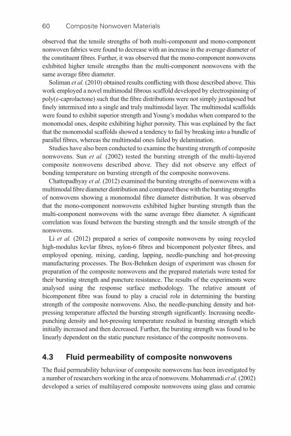
60 Composite Nonwoven Materials
observed that the tensile strengths of both multi- component and mono- component nonwoven fabrics were found to decrease with an increase in the average diameter of the constituent fi bres. Further, it was observed that the mono- component nonwovens exhibited higher tensile strengths than the multi- component nonwovens with the same average fi bre diameter.
Soliman et al. (2010) obtained results confl icting with those described above. This work employed a novel multimodal fi brous scaffold developed by electrospinning of poly( ε -caprolactone) such that the fi bre distributions were not simply juxtaposed but fi nely intermixed into a single and truly multimodal layer. The multimodal scaffolds were found to exhibit superior strength and Young’s modulus when compared to the monomodal ones, despite exhibiting higher porosity. This was explained by the fact that the monomodal scaffolds showed a tendency to fail by breaking into a bundle of parallel fi bres, whereas the multimodal ones failed by delamination.
Studies have also been conducted to examine the bursting strength of composite nonwovens. Sun et al. (2002) tested the bursting strength of the multi- layered composite nonwovens described above. They did not observe any effect of bonding temperature on bursting strength of the composite nonwovens.
Chattopadhyay et al. (2012) examined the bursting strengths of nonwovens with a multimodal fi bre diameter distribution and compared these with the bursting strengths of nonwovens showing a monomodal fi bre diameter distribution. It was observed that the mono- component nonwovens exhibited higher bursting strength than the multi- component nonwovens with the same average fi bre diameter. A signifi cant correlation was found between the bursting strength and the tensile strength of the nonwovens.
Li et al. (2012) prepared a series of composite nonwovens by using recycled high- modulus kevlar fi bres, nylon-6 fi bres and bicomponent polyester fi bres, and employed opening, mixing, carding, lapping, needle- punching and hot- pressing manufacturing processes. The Box-Behnken design of experiment was chosen for preparation of the composite nonwovens and the prepared materials were tested for their bursting strength and puncture resistance. The results of the experiments were analysed using the response surface methodology. The relative amount of bicomponent fi bre was found to play a crucial role in determining the bursting strength of the composite nonwovens. Also, the needle- punching density and hot- pressing temperature affected the bursting strength signifi cantly. Increasing needle- punching density and hot- pressing temperature resulted in bursting strength which initially increased and then decreased. Further, the bursting strength was found to be linearly dependent on the static puncture resistance of the composite nonwovens.
4.3 Fluid permeability of composite nonwovens
The fl uid permeability behaviour of composite nonwovens has been investigated by a number of researchers working in the area of nonwovens. Mohammadi et al. (2002) developed a series of multilayered composite nonwovens using glass and ceramic
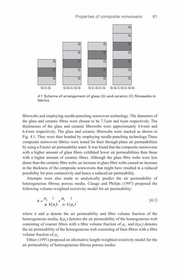
Properties of composite nonwovens 61
fi brewebs and employing needle- punching nonwoven technology. The diameters of the glass and ceramic fi bres were chosen to be 7.3 μ m and 6 μ m respectively. The thicknesses of the glass and ceramic fi brewebs were approximately 4.6 mm and 6.4 mm respectively. The glass and ceramic fi brewebs were stacked as shown in Fig. 4.1 . They were then bonded by employing needle- punching technology.These composite nonwoven fabrics were tested for their through- plane air permeabilities by using a Frazier air permeability tester. It was found that the composite nonwovens with a higher amount of glass fi bres exhibited lower air permeabilities than those with a higher amount of ceramic fi bres. Although the glass fi bre webs were less dense than the ceramic fi bre webs, an increase in glass fi bre webs caused an increase in the thickness of the composite nonwovens that might have resulted in a reduced possibility for pore connectivity and hence a reduced air permeability.
Attempts were also made to analytically predict the air permeability of heterogeneous fi brous porous media. Clauge and Philips (1997) proposed the following volume- weighted resistivity model for air permeability:
[4.1]
where k and μ denote the air permeability and fi bre volume fraction of the heterogeneous media, k ( μ 1 ) denotes the air permeability of the homogeneous web consisting of coarser fi bres with a fi bre volume fraction of μ 1 , and k ( μ 2 ) denotes the air permeability of the homogeneous web consisting of fi ner fi bres with a fi bre volume fraction of μ 2 .
Ethier (1991) proposed an alternative length- weighted resistivity model for the air permeability of heterogeneous fi brous porous media:
4.1 Scheme of arrangement of glass (G) and ceramic (C) fi brewebs in fabrics.
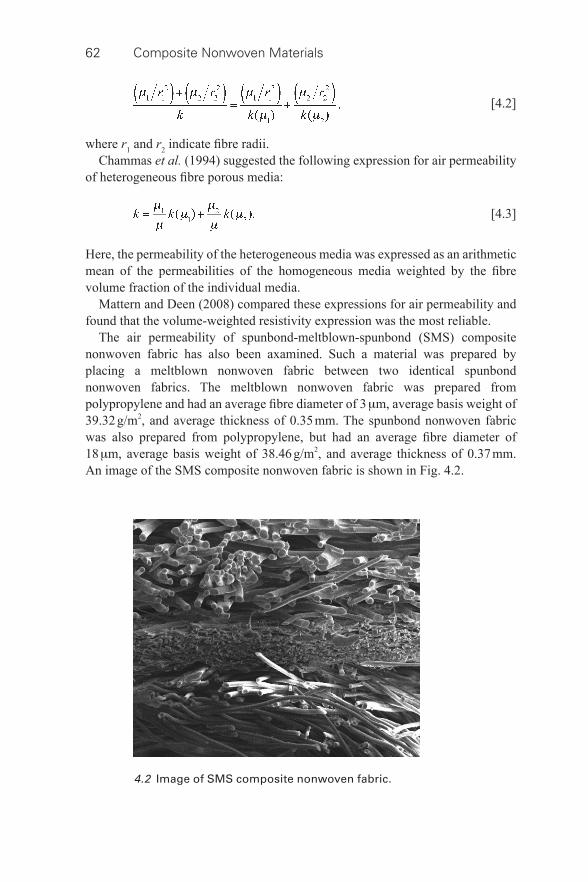
62 Composite Nonwoven Materials
[4.2]
where r 1 and r 2 indicate fi bre radii. Chammas et al. (1994) suggested the following expression for air permeability
of heterogeneous fi bre porous media:
[4.3]
Here, the permeability of the heterogeneous media was expressed as an arithmetic mean of the permeabilities of the homogeneous media weighted by the fi bre volume fraction of the individual media.
Mattern and Deen (2008) compared these expressions for air permeability and found that the volume- weighted resistivity expression was the most reliable.
The air permeability of spunbond- meltblown-spunbond (SMS) composite nonwoven fabric has also been axamined. Such a material was prepared by placing a meltblown nonwoven fabric between two identical spunbond nonwoven fabrics. The meltblown nonwoven fabric was prepared from polypropylene and had an average fi bre diameter of 3 μ m, average basis weight of 39.32 g/m 2 , and average thickness of 0.35 mm. The spunbond nonwoven fabric was also prepared from polypropylene, but had an average fi bre diameter of 18 μ m, average basis weight of 38.46 g/m 2 , and average thickness of 0.37 mm.An image of the SMS composite nonwoven fabric is shown in Fig. 4.2 .
4.2 Image of SMS composite nonwoven fabric.
Properties of composite nonwovens 63
The composite nonwoven fabric was tested for its through- plane air permeability by using a Frazier air permeability tester and the results of the experiments were compared for the individual meltblown and spunbond nonwoven fabrics. The air permeability of the SMS composite nonwoven fabric was measured to be 7.97 cm 3 /cm 2 ·s whereas that of the meltblown and spunbond fabrics were determined to be 8.91 cm 3 /cm 2 ·s and 63.23 cm 3 /cm 2 ·s. The presence of the meltblown layer was thus found to reduce the air permeability of the SMS composite fabric.
Adams and Rebenfeld (1991a) investigated the in- plane fl uid permeability characteristics of a heterogeneous multilayer fabric assembly by employing an in- plane fl ow technique and comparing the results to those of homogeneous multilayer fabric assemblies which were prepared by placing an isotropic nonwoven fabric onto an isotropic screening fabric. The isotropic screening fabric was found to have an in- plane permeability of 667 darcy whilst the isotropic nonwoven fabric had an in- plane permeability of 220 darcy.
It was observed that a homogeneous fabric assembly consisting of two layers of the nonwoven fabric yielded virtually the same in- plane permeability as a homogeneous fabric assembly consisting of one layer of the nonwoven fabric. A similar observation was reported in the case of an isotropic screening fabric. However, when the nonwoven fabric was placed over the screening fabric the resulting heterogeneous fabric assembly showed an in- plane permeability of 327 darcy. It was thus concluded that the fl uid permeability of the heterogeneous multilayer fi bre network differed from those of its constituent layers. Further, it was found that the effective in- plane permeabilities of heterogeneous assemblies were governed by the high permeability layers.
Permeability of the multilayer fi bre network was modelled as a weighted average of the permeabilities of the individual layers by Adams and Rebenfeld (1991b) according to;
[4.4]
where k 1 and k 2 indicate the permeability of the fi rst and second layers, and T 1 and T 2 refer to the thicknesses of the fi rst and second layers. This model was claimed to have good predictive capability.
Hollowell et al. (2013) investigated the air permeability characteristics of hybrid mixed media nonwovens composed of macro- and micro- fi bres. They developed a series of hybrid mixed media nonwovens by hydroentangling a homo- component spunbond fabric sandwiched between two layers of 16-segmented pie bi- component spunbond fabric. The air permeability of this structure was compared with that of conventional 100% 16-segmented pie nonwoven fabric. The mixed media nonwovens were found to offer higher air permeabilities than the conventional nonwovens. A tentative explanation for this behaviour was that the homocomponent layer sandwiched between the two
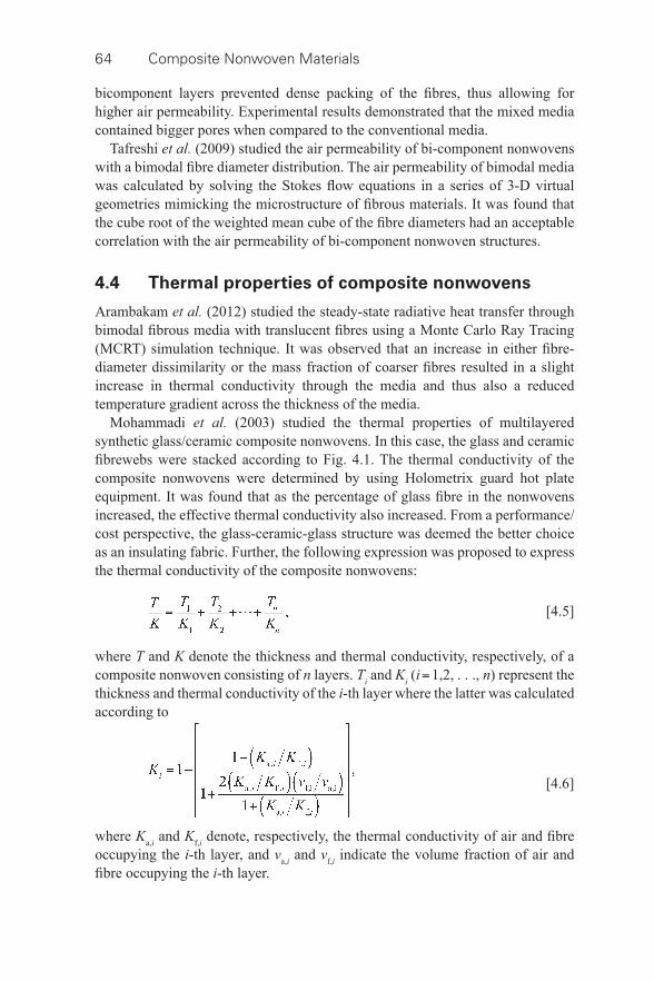
64 Composite Nonwoven Materials
bicomponent layers prevented dense packing of the fi bres, thus allowing for higher air permeability. Experimental results demonstrated that the mixed media contained bigger pores when compared to the conventional media.
Tafreshi et al. (2009) studied the air permeability of bi- component nonwovens with a bimodal fi bre diameter distribution. The air permeability of bimodal media was calculated by solving the Stokes fl ow equations in a series of 3-D virtual geometries mimicking the microstructure of fi brous materials. It was found that the cube root of the weighted mean cube of the fi bre diameters had an acceptable correlation with the air permeability of bi- component nonwoven structures.
4.4 Thermal properties of composite nonwovens
Arambakam et al. (2012) studied the steady- state radiative heat transfer through bimodal fi brous media with translucent fi bres using a Monte Carlo Ray Tracing (MCRT) simulation technique. It was observed that an increase in either fi bre- diameter dissimilarity or the mass fraction of coarser fi bres resulted in a slight increase in thermal conductivity through the media and thus also a reduced temperature gradient across the thickness of the media.
Mohammadi et al. (2003) studied the thermal properties of multilayered synthetic glass/ceramic composite nonwovens. In this case, the glass and ceramic fi brewebs were stacked according to Fig. 4.1 . The thermal conductivity of the composite nonwovens were determined by using Holometrix guard hot plate equipment. It was found that as the percentage of glass fi bre in the nonwovens increased, the effective thermal conductivity also increased. From a performance/cost perspective, the glass- ceramic-glass structure was deemed the better choice as an insulating fabric. Further, the following expression was proposed to express the thermal conductivity of the composite nonwovens:
[4.5]
where T and K denote the thickness and thermal conductivity, respectively, of a composite nonwoven consisting of n layers. T i and K i ( i = 1,2, . . ., n ) represent the thickness and thermal conductivity of the i -th layer where the latter was calculated according to
[4.6]
where K a, i and K f, i denote, respectively, the thermal conductivity of air and fi bre occupying the i -th layer, and v a, i and v f, i indicate the volume fraction of air and fi bre occupying the i -th layer.
Properties of composite nonwovens 65
Banks-Lee et al. (2004) compared the thermal conductivity of composite nonwovens with the air permeability of the same and obtained a very high degree of correlation. Mao and Russell (2007) observed that a lightweight wool web incorporated into a warp knitted spacer fabric by means of hydroentanglement resulted in an improvement of the thermal insulation properties of the composite nonwovens. This was ascribed to a reduction in convection through the fabric and an increase in refl ection of the heat radiating from the surface of the fabric due to the presence of the wool fi bre layer. Barker and Heniford (2011) suggested that the use of a thin fi bre layer in a multilayered composite structure would be a very effective method of increasing thermal insulation without changing the thickness and basis weight of the structure.
4.5 Liquid sorption characteristics of
composite nonwovens
Composite nonwovens were also studied for their liquid sorption behaviour. Rengasamy et al. (2011) investigated the liquid sorption behaviour of spunbond- meltblown-spunbond (SMS) composite nonwovens of 45 g/m 2 basis weight and 0.35 mm thickness. In the same study, they also examined the liquid sorption behaviour of one spunbond nonwoven of 40 g/m 2 basis weight and 0.32 mm thickness and two meltblown nonwovens of 70 g/m 2 and 50 g/m 2 basis weight and 0.60 mm and 0.55 mm thickness, respectively. An in- house fabricated Gravimetric Absorption Testing System (GATS) was used for determination of the liquid sorption characteristics of the media. The liquid sorption capacity was found to be highest with the spunbond nonwoven fabric of 40 g/m 2 basis weight, followed by, in order, the meltblown fabric of 50 g/m 2 basis weight, meltblown fabric of 70 g/m 2 basis weight, and SMS composite nonwoven of 45 g/m 2 basis weight. A similar ranking was found for the liquid sorption rate. The composite nonwoven showed poor absorbency attributed to its inability to draw water to its top spunbond layer from the middle meltblown layer. When the surface capillaries of the composite nonwovens were supported with plates, spread of liquid took place at a faster rate. The liquid spreading length was found to be predicted reasonably well by the model developed by Kim and Pourdeyhimi (2003) based on the expression given for the directional permeability by Mao and Russel (2000).
Das et al. (2008) reported a method of preparation of an absorbent core for ultrathin sanitary napkins using blends of superabsorbent fi bres and viscose fi bres. The superabsorbent/viscose fi bre blended carded webs were sandwiched between two layers of nonwoven fabrics, one made of parallel- laid viscose fi bres and the other prepared from random laid viscose fi bres. The prepared napkin samples showed an excellent rate of absorption of saline solution. Liquid transport was tested using a UMIST wettability tester, and it was observed that as the proportion of superabsorbent fi bres in the absorbent core increased, the resulting composite fabrics exhibited quicker absorption.
66 Composite Nonwoven Materials
Das et al. (2012a) studied the liquid sorption behaviour of composite nonwoven fabrics prepared by layer- wise mixing of superabsorbent fi bres and regular polypropylene fi bres by using a GATS. The tests showed better sorption capacity and better sorption rate when the liquid was fi rst introduced to the polypropylene fi bre side of the composite fabric rather than the superabsorbent fi bre side. This was attributed to the superabsorbent fi bres swelling and blocking the inter- fi bre pores. However liquid that fi rst encountered the inter- fi bre pores of polypropylene could easily later diffuse into the superabsorbent fi bres.
Liu et al. (2008) examined the wetting behaviour of an electrospun poly(L-lactic acid)/poly(vinyl alcohol) composite nonwoven. It exhibited better wettability than pure PLLA electrospun fi breweb and the wettability increased with increasing PVA content. A strong affi nity between the hydrophilic group of PVA and the water molecules was proposed as a tentative explanation for this effect. Further, higher surface roughness led to a reduction of contact angles, and a smaller fi bre diameter and smaller pore size resulted in a higher capillary pressure and thus higher water adsorption.
Chen et al. (2011) reported on the liquid sorption behaviour of a green composite nonwoven fabric prepared by using mixtures of lyocell, polylactic acid, and cotton fi bres and employing a needle- punching nonwoven line. The line was comprised of an opening and mixing machine, carding machine, laying machine, and needle- punching machine. The water absorbency test was carried out as per the CNS 5611 standard. It was observed that the composite fabric absorbed more water when it contained more tencel fi bres which phenomenon was ascribed to the molecular chain of the tencel fi bres having many hydroxyl groups that enable water molecules to bond. They further observed that a higher needling density resulted in more water absorption both in the machine and cross- machine directions.
Das et al. (2012a) attempted to develop composite nonwoven structures by combining ‘normal’ plus ‘super’ absorbent materials to achieve enhanced liquid sorption behaviour. Four sets of composite nonwoven materials were developed by random mixing of superabsorbent fi bres with 4DG, trilobal, or regular polyester fi bres in different mass proportions and by employing a laboratory- based needle- punching line. The materials developed were tested for their liquid absorption behaviour using distilled water as a test liquid in a GATS. It was observed that the composite nonwovens prepared with a higher amount of superabsorbent fi bres showed a higher liquid sorption capacity and liquid sorption rate.
4.6 Particle fi ltration behaviour of
composite nonwovens
Composite nonwovens are widely used for the separation of air- borne particles from a polluted air stream. Fotovati et al. (2010) studied the capture effi ciency and pressure drop of bi- component nonwovens showing a bimodal fi bre diameter distribution. They presented a criterion for defi ning an equivalent
Properties of composite nonwovens 67
unimodal diameter distribution for their fi lter media and took advantage of the existing classical expressions for predicting the pressure drop and collection effi ciency of bimodal fi brous media. They concluded that the cube root averaged diameter concept of Tafreshi et al. (2009) could be used to design a bimodal fi lter media quite successfully.
Jaganathan et al. (2008) studied the pressure drop across bi- component fi lter media composed of fi bres showing bimodal diameter distributions. They observed that the area- weighted average of the fi bre diameters in a bimodal fi lter, as proposed by Brown and Thorpe (2001), resulted in a relatively good estimation of an equivalent unimodal fi bre diameter. Such averaging, however, left the pressure drop prediction sensitive to the ratio of fi bre diameters and the distribution of fi bre diameters. The authors proposed a correction factor accounting for both effects.
As reported by Hutten (2007), composite structures can be used for the following purposes:
• One or more layers can provide the required mechanical support for the other layer(s) responsible for fi ltration.
• one layer can serve as a prefi lter layer for the layer responsible for fi ltration. • Different layers can be organized in a manner to manipulate the gradient in
density of the medium so that each layer provides a higher level of fi ltration effi ciency to remove smaller and smaller particles.
• different separation technologies can be combined into one fi lter medium so that, for example, in the case of cabin air fi lters, an activated carbon layer is combined with one or more nonwoven layers, where the nonwoven layers fi lter out particles by means of mechanical capture mechanisms and the activated carbon layer separates molecular contaminants by means of chemical capture mechanisms.
• The outer layers can serve as a containment to inhibit medium migration, dusting, and particle fallout from the inner layers.
Thakur et al. (2013) prepared a spunbond- meltblown-spunbond (SMS) composite nonwoven fi lter medium where the meltblown layer was electrostatically charged. This material was tested for fi ltration effi ciency and found to capture air- borne micro particles quite effectively. Yuksekkaya et al. (2010) developed a hybrid woven- nonwoven composite material also for air fi ltration application. They observed higher fi ltration effi ciency as well as a higher pressure drop due to woven fabric reinforcement, and for the same reason, the bursting strength of the composite structure was found to increase, indicating potentially higher life of the fi lter.
To understand the role of individual layers in composite nonwoven fi lters, a systematic study was presented by Das et al. (2012b). They took an approach based on a computer simulation technique to generate virtual composite fi brous structures and to simulate the aerosol fi ltration behaviour of such fi lter media. A series of virtual composite fi lter structures were generated using GeoDict codes.
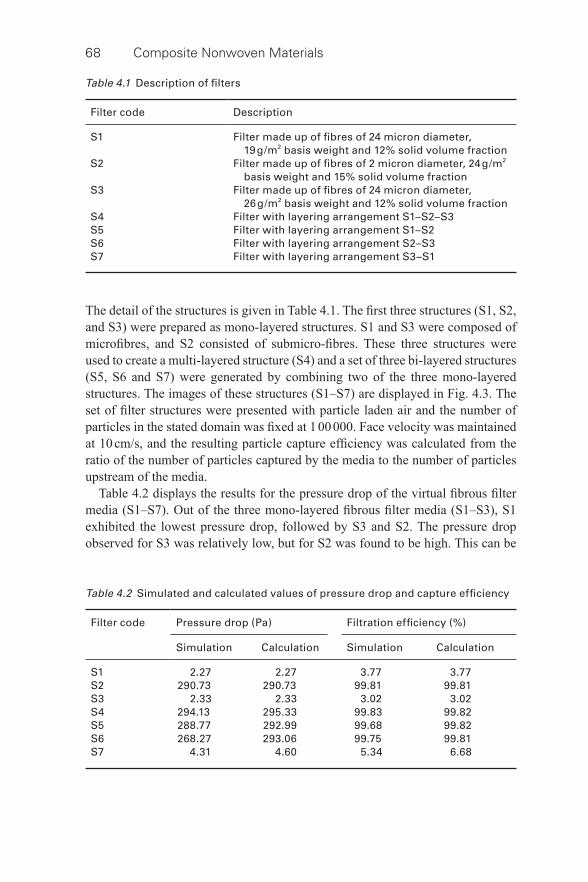
68 Composite Nonwoven Materials
The detail of the structures is given in Table 4.1 . The fi rst three structures (S1, S2, and S3) were prepared as mono- layered structures. S1 and S3 were composed of microfi bres, and S2 consisted of submicro- fi bres. These three structures were used to create a multi- layered structure (S4) and a set of three bi- layered structures (S5, S6 and S7) were generated by combining two of the three mono- layered structures. The images of these structures (S1–S7) are displayed in Fig. 4.3 . The set of fi lter structures were presented with particle laden air and the number of particles in the stated domain was fi xed at 1 00 000. Face velocity was maintained at 10 cm/s, and the resulting particle capture effi ciency was calculated from the ratio of the number of particles captured by the media to the number of particles upstream of the media.
Table 4.2 displays the results for the pressure drop of the virtual fi brous fi lter media (S1–S7). Out of the three mono- layered fi brous fi lter media (S1–S3), S1 exhibited the lowest pressure drop, followed by S3 and S2. The pressure drop observed for S3 was relatively low, but for S2 was found to be high. This can be
Table 4.1 Description of fi lters
Filter code Description
S1 Filter made up of fi bres of 24 micron diameter, 19 g/m 2 basis weight and 12% solid volume fraction
S2 Filter made up of fi bres of 2 micron diameter, 24 g/m 2 basis weight and 15% solid volume fraction
S3 Filter made up of fi bres of 24 micron diameter, 26 g/m 2 basis weight and 12% solid volume fraction
S4 Filter with layering arrangement S1–S2–S3 S5 Filter with layering arrangement S1–S2 S6 Filter with layering arrangement S2–S3 S7 Filter with layering arrangement S3–S1
Table 4.2 Simulated and calculated values of pressure drop and capture effi ciency
Filter code Pressure drop (Pa) Filtration effi ciency (%)
Simulation Calculation Simulation Calculation
S1 2.27 2.27 3.77 3.77 S2 290.73 290.73 99.81 99.81 S3 2.33 2.33 3.02 3.02 S4 294.13 295.33 99.83 99.82 S5 288.77 292.99 99.68 99.82 S6 268.27 293.06 99.75 99.81 S7 4.31 4.60 5.34 6.68
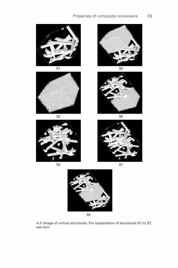
Properties of composite nonwovens 69
4.3 Image of virtual structures. For explanation of structures S1 to S7, see text.
70 Composite Nonwoven Materials
explained by the negative effect of the higher surface area occupied by the fi bres in the fi lter media. Though S1 and S3 were made up of the same fi bres, the basis weight of S1 was less than that of S3 and as a result, the number of fi bres occupying per unit area of S1 was less than for S3. S2 was comprised of fi ner fi bres than S1 and S3 and the basis weight of S2 was higher than that of S1, but a little less than that of S3. As a result, the number of fi bres occupying per unit area of S2 was higher than for both S1 and S3. The surface area occupied by the fi bres in S2 was thus also higher than for S1 and S3, resulting in a higher pressure drop for S2. For the same reason, the presence of S2 in the two bi- layered media (S5 and S7) and in the multi- layered media (S4) resulted in a similarly high pressure drop. The remaining bi- layered medium (S7), because of the absence of S2, exhibited a relatively low pressure drop.
An attempt was made to predict the pressure drop of the bi- layered and multi- layered fi lter media from the pressure drop of the mono- layered fi lter media by using the following expression:
[4.7]
where Δ p i denotes the pressure drop of the i -th layer and Δ p Σ indicates the pressure drop of a fi brous fi lter medium consisting of n number of layers.
The results of this exercise are shown in Table 4.2 where it can be seen that the proposed expression is in fairly good agreement with the simulation results.
The particle capture effi ciency of the virtual fi brous fi lter media (S1–S7) at the most penetrating particle size of 0.3 micrometer diameter is given in Table 4.2 . It can be seen that among the three mono- layered fi lter media (S1–S3), S2 exhibited the highest capture effi ciency, followed by S1 and S3. As the surface area occupied by the fi bres per unit area of S2 was the highest, it was expected that the capture effi ciency of S2 would be the highest. Similarly, as the surface area occupied by the fi bres per unit area of S3 was higher than that of S1, the capture effi ciency of S3 was expected to be higher than the capture effi ciency of S1, which however was not found to be the case. The reason for this behaviour is not yet known.
Because of the presence of S2, the bi- layered media (S5 and S6) and the multi- layered medium (S4) yielded a high capture effi ciency. The remaining bi- layered medium (S7), because of the absence of S2, exhibited a relatively low capture effi ciency.
An attempt was made to correlate the particle capture effi ciency of the bi- layered and multi- layered fi lter media with the capture effi ciency of the mono- layered fi lter media according to
[4.8]
Properties of composite nonwovens 71
where E i denotes the capture effi ciency of the i -th layer and E Σ indicates the capture effi ciency of a fi brous fi lter media consisting of n number of layers. The results are shown in Table 4.2 . Again, a good agreement with the simulation results was observed.
4.7 Conclusion
The physical properties of composite nonwoven materials including tensile strength, breaking elongation, bursting strength, fl uid permeability, thermal conductivity, liquid sorption and particle fi ltration are discussed. The roles of fi bre material and the internal structure on the aforesaid properties of composite nonwovens are described.
4.8 Sources of further information and advice
Composite nonwovens are engineered materials. They provide a solution through creation of multi- functional and economical products through streamlining of manufacturing processes and by the replacement of two or more products by a single one. Good sources of information to monitor on- going developments include the Textile Research Journal , Journal of the Textile Institute , and the Journal of Engineered Fibres and Fabrics . Furthermore, the nonwoven trade journals such as Nonwovens Industry and the publications of trade associations such as the INDA and EDANA are useful sources of knowledge.
4.9 References
Adams , K. L. and Rebenfeld , L. ( 1991 a), ‘ Permeability characteristics of multilayer fi bre reinforcements, Part I: Experimental observations ’, Polymer Composites , 12 , 179 – 185 .
Adams , K. L. and Rebenfeld , L. ( 1991 b), ‘ Permeability characteristics of multilayer fi bre reinforcements, Part II: Theoretical model ’, Polymer Composites , 12 , 186 – 190 .
Arambakam , R. , Tafreshi , H. V. , and Pourdeyhimi , B. ( 2012 ), ‘ Analytical Monte Carlo Ray Tracing simulation of radiative heat transfer through bimodal fi brous insulations with translucent fi bres ’, International Journal of Heat and Mass Transfer , 55 , 7234 – 7246 .
Banks-Lee , P. , Mohammadi , M. , and Ghadimi , P. ( 2004 ), ‘ Utilization of air permeability in predicting the thermal conductivity ’, International Nonwovens Journal , Summer, 28 – 33 .
Barker, R. L. and Heniford, R. C. ( 2011 ), ‘ Factors affecting the thermal insulation and abrasion resistance of heat resistant hydro- entangled nonwoven batting materials for use in fi refi ghter turnout suit thermal liner systems ’, Journal of Engineered Fibres and Fabrics , 6 , 1 – 10 .
Brown , R. C. and Thorpe , A. ( 2001 ), ‘ Glass- fi bre fi lters with bimodal fi bre size distributions ’, Powder Technology , 118 , 3 – 9 .
Chammas , P. , Federspiel , W. J. , and Eisenberg , S. R. ( 1994 ), ‘ A microcontinuum model of electrokinetic coupling in the extracellular matrix: perturbation formulation and solution ’, Journal of Colloid and Interface Science , 168 , 526 – 538 .
72 Composite Nonwoven Materials
Chattopadhyay , R. , Das , D. , and Pradhan , A. K. ( 2012 ), ‘ Studies on multi- component nonwoven fi lter media ’, Fibre Society Spring Conference , Switzerland .
Chen , A-P. , Lou , C-W. , Lin , J-Y. , Lin , T-A. , and Lin , J-H. ( 2011 ), ‘ Manufacturing techniques and physical properties of the green composite nonwoven fabrics ’, Proceedings of 11th Asian Textile Conference , Daegu , 801 – 806 .
Clague , D. S. and Phillips , R. J. ( 1997 ), ‘ A numerical calculation of the hydraulic permeability of three- dimensional disordered fi brous media ’, Physics of Fluids , 9 , 1562 – 1573 .
Das , A. , Kothari , V. K. , Makhija , S. , and Avyaya , K. ( 2008 ), ‘ Development of high- absorbent light- weight sanitary napkin ’, Journal of Applied Polymer Science , 107 , 1446 – 1470 .
Das , D. , Pradhan , A. K. , and Thakur , R. ( 2012 b), Design Strategy of Respirator Filters , Healthcare India 2012 , New Delhi, India .
Das , D. , Rengasamy , R. S. , and Kumar , M. ( 2012 a), ‘ Studies on composite nonwoven liquid absorbent media ’, 41st Textile Research Symposium , Minho, Portugal .
Ethier , C. R. ( 1991 ), ‘ Flow through mixed fi brous porous materials ’, AIChE Journal , 37 , 1227 – 1236 .
Fotovati , S. , Tafreshi , H. V. , and Pourdeyhimi , B. ( 2010 ), ‘ Capture effi ciency and pressure drop of bimodal fi lter media ’, American Filtration and Separation Society , March 22 – 15 , San Antonio, USA .
Haghi , A. K. and Zaikov , G. ( 2012 ), Advances in Nanofi bre Research , Volume 2 , Smithers Rapra Technology .
Hollowell , K. B. , Anantharamaiah , N. , and Pourdeyhimi , B. ( 2013 ), ‘ Hybrid mixed media nonwovens composed of macrofi bres and microfi bres, Part I: Three- layer segmented pie confi guration ’, Journal of Textile Institute , DOI: 10.1080/00405000.2013.767430.
Hutten , I. M. ( 2007 ) Handbook of Nonwoven Filter Media , Elsevier, Netherlands . Jaganathan , S. , Tafreshi , H. V. , and Pourdeyhimi , B. ( 2008 ), ‘ On the pressure drop
prediction of fi lter media composed of fi bres with bimodal diameter distributions ’, Powder Technology , 181 , 89 – 95 .
Kim , H. S. and Pourdeyhimi , B. P. ( 2003 ), ‘ In- plane liquid distribution in nonwoven fabrics, Part II: Simulation ’, International Nonwovens Journal , 12 , 29 – 33 .
Li , T-T. , Wang , R. , Lou , C. W. , and Lin , J-H. ( 2012 ), ‘ Evaluation of high- modulus, puncture- resistance composite nonwoven fabrics by response surface methodology ’, Journal of Industrial Textiles , DOI: 10.1177/1528083712452900.
Liu , Y. , Wu , N. , Wei , Q. , Cai , Y. , and Wei , A. ( 2008 ), ‘ Wetting behaviour of electrospun poly(L-lactic acid)/poly(vinyl alcohol) composite nonwovens ’, Journal of Applied Polymer Science , 110 , 3172 – 3177 .
Mao, N. and Russell, S. J. ( 2007 ), ‘ The thermal insulation properties of spacer fabrics with a mechanically integrated wool fi bre surface ’, Textile Research Journal , 77 , 914 – 922 .
Mao , N. and Russel , S. J. ( 2000 ), ‘ Directional permeability in homogeneous nonwoven structures, Part I: The relationship between directional permeability and fi bre orientation ’, Journal of Textile Institute , 91 , 235 – 243 .
Mattern, K. J. and Deen , W. M. ( 2008 ), ‘ Mixing rules for estimating the hydraulic permeability of fi bre mixtures ’, Journal of American Institute of Chemical Engineers , 54 , 32 – 41 .
Mohammadi , M. , Banks-Lee , P. , and Ghadimi , P. ( 2002 ), ‘ Air permeability of multilayer needlepunched nonwoven fabrics: Experimental method ’, Journal of Industrial Textiles , 32 , 139 – 150 .
Properties of composite nonwovens 73
Mohammadi , M. , Banks-Lee , P. , and Ghadimi , P. ( 2003 ), ‘ Determining effective thermal conductivity of multilayered nonwoven fabrics ’, Textile Research Journal , 73 , 802 – 808 .
Rengasamy , R. S. , Kothari , V. K. , Bele , V. S. , and Khanna , R. ( 2011 ), ‘ Liquid sorption behaviour of nonwovens ’, Journal of Textile Institute , 102 , 1019 – 1030 .
Russel , S. J. ( 2007 ) Handbook of Nonwovens , Woodhead Publishing Ltd. , U.K. Soliman , S. , Pagliari , S. , Rinaldi , A. , Forte , G. , Fiaccavento , R. , et al. ( 2010 ), ‘ Multiscale
three- dimensional scaffolds for soft tissue engineering via multimodal electrospinning ’, Acta Biomaterialia , 6 , 1227 – 1237 .
Sun , C. , Zhang , D. , Wadsworth , L. C. , and McLean , M. ( 2002 ), ‘ Development of innovative cotton- surface nonwoven laminates ’, Journal of Industrial Textiles , 31 , 179 – 188 .
Tafreshi , V. H. , Rahman , M. S. A. , Jaganathan , S. , Wang , Q. , and Pourdeyhimi , B. ( 2009 ), ‘ Analytical expressions for predicting permeability of bimodal fi brous porous media ’, Chemical Engineering Science , 64 , 1154 – 1159 .
Tausif , M. and Russel , S. J. ( 2012 ), ‘ Characterisation of the z- directional tensile strength of composite hydroentangled nonwovens ’, Polymer Testing , 31 , 944 – 952 .
Thakur , R. , Das , D. , and Das , A. ( 2013 ), ‘ Electret fi brous air fi lter media ’, Twenty- sixth National Convention of Textile Engineers , Bhopal, India .
Yuksekkaya , M. E. , Tercan , M. , and Dogan , G. ( 2010 ), ‘ An experimental investigation of nonwoven fi lter cloth with and without reinforcement of woven fabric ’, Journal of Textile Institute , 101 , 950 – 957 .
74
© 2014 Woodhead Publishing Limited
5 Composite nonwovens in absorbent
hygiene products
D. DAS, Indian Institute of Technology Delhi, India
DOI: 10.1533/9780857097750.74
Abstract: This chapter reports on the use of composite nonwoven materials in absorbent hygiene products. It begins with an introduction to absorbent hygiene products and examines the considerations for the use of composite nonwovens in these products. It then proceeds to describe three important absorbent hygiene products, namely baby diapers, feminine sanitary pads, and adult incontinence pads, and informs about the recent developments that have been taking place on these products. To conclude, the chapter highlights the challenges and promises for absorbent hygiene products.
Key words: composite nonwoven, hygiene product, baby diaper, sanitary pad, adult incontinence pad.
5.1 Introduction
Absorbent hygiene products such as baby care products, feminine hygiene products and adult incontinence products are an essential part of everyday life. Baby care products include baby diapers, training pants, dry and wet baby wipes. Feminine hygiene products encompass sanitary pads, tampons, panty shields, interlabial devices, wipes and cosmetic removal pads. Adult incontinence products cover adult incontinence pads, adult pant diapers, underpads, personal/medicated wipes, and nursing pads. Amongst these products, baby diapers, sanitary pads and adult incontinence pads are the three mostly used disposable absorbent hygiene products.
In the past few decades, the overwhelming majority of innovations in absorbent hygiene products came through composites of nonwovens prepared by using a combination of different materials and different technologies. A large number of possibilities of combining different materials and different technologies was tried. Of them, some are continuously being used in commercial products. The greatest emphasis in the development of composite nonwovens was placed on the use of spunmelt systems (Chatterjee and Gupta, 2002). Examples include spunbond/meltblown (SM), spunbond/meltblown/spunbond (SMS) and spunbond/meltblown/meltblown/spunbond (SMMS). Besides, composite nonwovens were prepared by using air- laid/spunlace combination by incorporating fl uff pulp by air- lay technology into a web during spunlacing or by incorporating air- laid pulp with spunlace on a spunlace line. In addition, there were developments of
Absorbent hygiene products 75
polypropylene-polyethylene bicomponent spunbond nonwovens with poly-propylene core providing the strength and mechanical stability and polyethylene sheath contributing to the softness and greater ease of thermal bonding. Further, many interesting materials such as cotton surfaced spunbond composite nonwoven and cotton centred composite with spunbond and meltblown nonwoven forming the outer surfaces of absorbent hygiene products were also developed. Furthermore, composite nonwovens prepared by combining fl uff pulp and superabsorbent polymer granules have been widely used in a variety of disposable absorbent hygiene products.
5.2 Key material requirements
The primary and the most important function of absorbent hygiene products, exemplifi ed by baby diapers, sanitary pads, and adult incontinence pads, is to absorb bodily liquids such as urine and menstrual liquid (Allan, 2005). But attainment of this characteristic is not suffi cient because, from a hygienic point of view, after absorbing the liquid the surface of the product must be dry and also the absorbed liquid must be retained inside the product so that it should not leak to the outer surface.
In order to achieve this, the urine or menstrual liquid is required to pass through the surface layer and gets absorbed in the core and retained beneath the core. How is this possible? There are many approaches reported in the literature to tackle this tricky problem. A common solution states that the products are required to be comprised of a gradient of absorbency ranging from near zero at the surfaces to maximum in the core. This gradation is achieved by using a multi- layered composite of nonwoven materials wherein the constituents and their arrangement in each layer need to be appropriately chosen.
Typically, the most popular constituents in today’s disposable absorbent hygiene products include hydrophilic cellulosic fi bres (wood- derived fl uff pulp or viscose rayon), superabsorbent polymer granules or superabsorbent fi bres and hydrophobic polyester or polypropylene fi bres. The latter constitutes the surface of the product which is in contact with the skin. Despite their hydrophobicity, these fi bres can retain some amount of liquid, especially in the interstices of the porous surface layer. This layer is made as thin as possible to minimize the amount of liquid retained and to maximize the feel of dryness.
Further, the composition of the layer immediately below the thin surface layer is selected in such a way that it is capable of withdrawing the interstitial liquid therefrom. Of course, it is not suffi cient to merely move this liquid into a layer contiguous to the surface layer, it must be moved deeper into the product. This can be done by modifying the geometry of the pores. As known, the smaller the pore the greater is the capillary pressure driving the liquid. So, a layer with smaller pores would draw liquid from a chemically identical layer with larger pores nearer to the skin. But, this would obviously reduce the absorptive capacity of the
76 Composite Nonwoven Materials
product. This negative effect can be minimized by incorporating superabsorbent polymer or superabsorbent fi bre. However, upon absorbing liquid, these polymers or fi bres swell tremendously and form a liquid impermeable wall of gel, thus inhibiting the movement of liquid. This is why these polymers or fi bres must be distributed randomly within the fi bre mass. While the smaller superabsorbent particles result in faster absorption of liquid because of increased surface area, they have a tendency to fall out of the web. Nevertheless, this can be avoided by using superabsorbent fi bres.
Another way to infl uence the movement of liquids in these products requires using blends of hydrophilic and hydrophobic fi bres. The latter helps to prevent collapsing and matting of a wetted cellulosic fi bre mass. One can thus see that the composite nonwoven materials are offering a unique solution to achieve the desired movement of liquids, such as urine and menstrual liquid, through the complex structure of disposable absorbent hygiene products.
5.3 Baby diapers
5.3.1 Functions
The baby diaper is considered as one of the important disposable absorbent hygiene products today. The functions of a baby diaper are to (1) absorb the baby’s urine, (2) isolate wetness from the baby’s skin, (3) retain urine inside their absorbent core, (4) contain faeces, and (5) isolate urine and faeces from the babies environment. These functions should be accompanied by providing maximum comfort for the baby, a good fi t around babies legs and bottom, good practical usefulness, and less diaper rash for the baby. In order to achieve these functions, the requirements of a baby diaper are to
1 keep the surface layer as dry as possible in order to facilitate good skin care conditions;
2 transfer liquids from the surface through to an effective storage layer; 3 absorb and store transmitted liquids in such a way that they will not be released
back through the structure to the surface; 4 provide an effi cient containment system to contain the absorbent layers in
order to protect the user’s environment; 5 be capable of appropriate and environmentally compatible disposal after use.
5.3.2 Components
In the last few decades the baby diaper has evolved from a relatively simple structure comprising a large volume of fl uff pulp covered on one side by a nonwoven material and on the other side by a thin impervious fi lm, to a multi- layered complex structure where each layer has a specifi cally allocated task. Though there are many variations and combinations around this structure followed
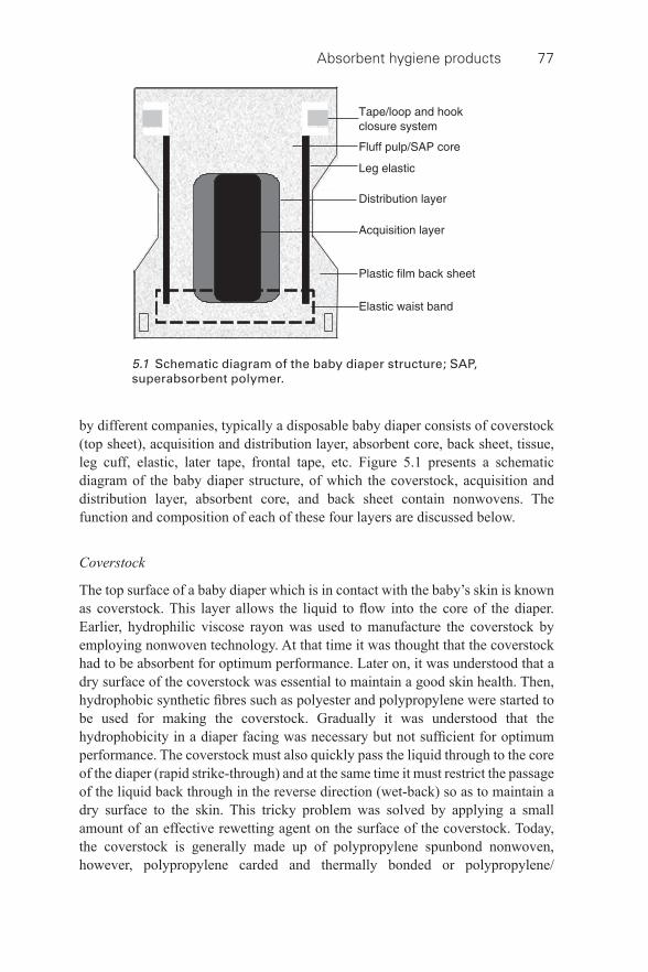
Absorbent hygiene products 77
by different companies, typically a disposable baby diaper consists of coverstock (top sheet), acquisition and distribution layer, absorbent core, back sheet, tissue, leg cuff, elastic, later tape, frontal tape, etc. Figure 5.1 presents a schematic diagram of the baby diaper structure, of which the coverstock, acquisition and distribution layer, absorbent core, and back sheet contain nonwovens. The function and composition of each of these four layers are discussed below.
Coverstock
The top surface of a baby diaper which is in contact with the baby’s skin is known as coverstock. This layer allows the liquid to fl ow into the core of the diaper. Earlier, hydrophilic viscose rayon was used to manufacture the coverstock by employing nonwoven technology. At that time it was thought that the coverstock had to be absorbent for optimum performance. Later on, it was understood that a dry surface of the coverstock was essential to maintain a good skin health. Then, hydrophobic synthetic fi bres such as polyester and polypropylene were started to be used for making the coverstock. Gradually it was understood that the hydrophobicity in a diaper facing was necessary but not suffi cient for optimum performance. The coverstock must also quickly pass the liquid through to the core of the diaper (rapid strike- through) and at the same time it must restrict the passage of the liquid back through in the reverse direction (wet- back) so as to maintain a dry surface to the skin. This tricky problem was solved by applying a small amount of an effective rewetting agent on the surface of the coverstock. Today, the coverstock is generally made up of polypropylene spunbond nonwoven, however, polypropylene carded and thermally bonded or polypropylene/
5.1 Schematic diagram of the baby diaper structure; SAP, superabsorbent polymer.
78 Composite Nonwoven Materials
polyethylene bicomponent spunbond nonwoven or lofty through- air bonded nonwovens or spunbond–meltblown composite SMS, SMMS, SSMMS structures are also used. A good overview on the use of these materials in coverstock is given by Chatterjee and Gupta (2002). An effective durable rewetting agent is uniformly applied onto this material to make it hydrophilic. Sometimes, in order to create novelties for product differentiation, several topical lotions are added to the nonwoven coverstock, such as aloe vera, almond oil, vitamin E, vitamin D, etc. The use of antibacterial lotions, such as tertiary ammonia or silver salt compounds onto the coverstock is, however, not recommended by many paediatricians.
Acquisition and distribution layer
This is an inner layer placed between the top sheet and the absorbent core. Though this is mostly used as a patch near the target zone where urine is most likely to be deposited, it sometimes is used in full length. This layer is needed especially when the absorbent core is very thin. It provides rapid acquisition, quick transport and thorough distribution of the liquid. Further, this layer is very important to give a sense of dryness to the skin by providing additional separation between the coverstock and the absorbent core. Also, it reduces potential leakage. This layer is generally used whenever the mix of superabsorbent polymer in the absorbent core exceeds about 15% by weight or when the liquid penetration time requires a boost in order to avoid diaper leakage due to liquid accumulation inside the diaper.
The acquisition and distribution layer generally takes the form of a multi- layered composite nonwoven material. The top layer is made up of coarser fi bres and has relatively large pores and high porosity, especially effective for acquisition of the liquid. The middle layer is made up of fi ne fi bres and has relatively small pores and low porosity and is especially effective for transferring the liquid into the core of the diaper. The bottom layer is made up of fi ner fi bres and has smaller pores and less porosity. As there is a gradient of porosity or density and pore size along the thickness of the material, there is a gradient of capillary pressure which would help to move a greater volume of liquid effectively to the absorbent core of the diaper. The acquisition and distribution layer is generally made of through- air bonded nonwovens, but an aperture fi lm made of perforated plastic has also been used successfully.
Absorbent core
The absorbent core is the heart of any disposable absorbent products and the baby diaper is no exception to this. It gives integrity and absorbing capacity to the diaper and placed in- between the acquisition and distribution layer and the back sheet. Today, the absorbent core of a baby diaper is mostly comprised of an optimum combination of fl uff pulp and superabsorbent polymer (SAP). The earlier diapers utilized fl uff pulp only; although this showed quite high absorption
Absorbent hygiene products 79
capacity when the diaper was in free swell, it showed less absorption capacity under pressure. What followed was the utilization of superabsorbent polymer in the absorbent core of a baby diaper. The superabsorbent polymer is typically used in fi ne granular form. It helps to increase liquid absorption capacity tremendously, but at the same time increases liquid retention capacity, thus allowing the product to be thinner with improved performance.
The dominant superabsorbents available in the market today are based on cross- linked sodium polyacrylate gels. In the molecular structure of sodium polyacrylate, there are sodium carboxylate groups hanging off the main chain. When it comes in contact with water, the sodium detaches itself, leaving only carboxyl ions. Being negatively charged, these ions repel one another so that the polymer unwinds and absorbs water, which is attracted by the sodium atoms. The polymer also has cross- links, which effectively leads to a three- dimensional structure. It has high molecular weight of more than a million; thus, instead of getting dissolved, it solidifi es into a gel. The hydrogen in water (H-O-H) is trapped by acrylate due to the atomic bonds associated with the polarity forces between the atoms. Electrolytes in the liquid, such as salt minerals (urine contains 0.9% of minerals), reduce polarity, thereby affecting superabsorbent properties, especially with regard to the superabsorbent capacity for liquid retention. Linear molecular confi gurations have less total capacity than non- linear molecules but, on the other hand, retention of liquid in a linear molecule is higher than that in a non- linear molecule, due to improved polarity. The detail physical chemistry of superabsorbent polymers can be found elsewhere (Chatterjee and Gupta, 2002).
Back sheet
The back sheet is used to prevent the absorbed liquid from leaking out of the diaper. The back sheet is a breathable but liquid impervious fi lm and it is generally made up of polyethylene. Sometimes, the back sheet is given a cloth- like look by adding a thin polypropylene non- woven sheet to the fi lm, using either the hot melt process or the heat and pressure method with direct extrusion to the nonwoven.
5.3.3 Recent developments
Disposable absorbent hygiene products are in general a subject of immense interest to a large number of product development scientists in many multi- national companies. The baby diaper, being one of the important disposable absorbent hygiene products, is not an exception to this. In the recent past, a series of patent disclosures was made on the baby diaper and its components. Interestingly, a few of them were based on composite nonwoven materials.
Seneviratne (2009) disclosed a patent on the development of biodegradable personal products such as the baby diaper comprising an outer cover, an absorbent core formed of starch grains or fl akes and hydrogel dispersed in viscose fl uff, a
80 Composite Nonwoven Materials
hydrophobic layer, a biodegradable fi lm and a hydrophilic layer such that the last three layers were formed by using polylactic acid. In another patent disclosure, Luo (2009) reported a novel absorbent structure for the use in disposable hygiene products comprised of at least two nonwoven meltblown lyocell fi brewebs with superabsorbent polymer placed in- between the two fi brewebs.
Wood et al. (2009) disclosed a disposable absorbent article made up of an absorbent material and a degradable thermoplastic polymer composition comprising an aliphatic polyester. An antimicrobial composition is formed into webs by melt extrusion, such as nonwovens and fi lms that are incorporated into disposable absorbent products. Amos et al. (2012) disclosed a disposable absorbent article comprising an absorbent material and an antimicrobial composition. The antimicrobial composition included a carrier comprising fatty alcohol, a poly(alkyleneoxy) polymer, and an antimicrobial agent. This composition might be coated onto component substrates such as nonwoven and fi lms that were incorporated in disposable absorbent articles. Udengaard et al. (2010) developed an absorbent hygiene article with barrier component, which comprised at least a spunbond web or a meltblown web, or a combination of both obtainable from a mixture of thermoplastic polymers and a selected organic melt- additive component.
Martin (2003) disclosed an elastic nonwoven sheet for the use in the manufacture of diapers, which was prepared by substantially uniformly impregnating a necked nonwoven substrate with an elastomeric polymer by treatment with an elastomeric solution. Coronado et al. (2004) reported an invention of a nonwoven laminate printed with graphics that exhibited a soft cloth- like feel and was lightweight, impermeable and suitable for application as a back sheet in disposable absorbent hygiene articles. Isele and Chhabra (2005) developed a nanofi bre web by employing a melt fi lm fi brillation process for use in a baby diaper as a barrier- on-core, outercover, and/or leg cuff. Nguyen (2006) developed a bonded nonwoven material comprising extensible fi bres for use in articles such as baby diapers. Barge et al. (2004) disclosed a liquid acquisition layer with improved caliper recovery and re- wet properties for the use in disposable absorbent products. Koczab (2002) disclosed a patent on composite nonwoven material for the use in absorbent hygiene articles, which was prepared by needle- bonding or thermo- bonding two carded fi bre layers such that one was comprised of higher denier fi bre than the other.
Fleissner (2001) developed a composite nonwoven material for the use in absorbent hygiene articles by hydroentangling a spunbond nonwoven fabric and a layer of pulp fi bres. Dharmadhikary et al. (2004) developed nonwoven products for hygiene application by laminating one or more nonwoven substrates and one or both sides of a cast fi lm produced by employing multiple extruders.
Sun et al. (2002) reported on development of innovative cotton- surfaced and cotton core nonwoven laminates for use in absorbent hygiene products. The cotton surfaced nonwovens were developed by applying cotton fi bres on one or both
Absorbent hygiene products 81
sides of a base structure, generally polypropylene spunbond web, and then laminating all the layers by employing the thermal calendar bonding technique. The cotton core nonwovens were prepared by laminating a cotton core layer with meltblown and/or spunbond webs by employing the thermal calendar bonding technique. These materials showed excellent soft hand, breathability, absorbency and tensile properties.
Wu et al. (2007) developed cost- effective microporous fi lms by using polyolefi nic material and inorganic fi llers for disposable hygiene articles. They also developed microporous composites by combining microporous fi lms with specialty fabrics such as nonwovens and thus obtained the advantages of the liquid barrier properties of the fi lm and the strength and aesthetics of the fabric. The composites were claimed to be used in disposable hygiene products.
5.4 Feminine sanitary pads
5.4.1 Functions
A feminine sanitary pad is another important disposable absorbent hygiene product. It’s functions are to (1) absorb menstrual liquid discharge, (2) isolate wetness from the skin, (3) retain menstrual liquid discharge, and (4) isolate menstrual liquid from the female’s environment. These functions should be accompanied by providing a feel of maximum comfort, having an aesthetic appearance, preventing odor, and staying in place.
5.4.2 Components
The feminine sanitary pad is constantly being innovated. Although the ultrathin products have begun to garner a higher market share, there is still a need for a thick product as it is believed to be a sign to most people of a good product with superior protection. Like baby diapers, this product is also a multi- layered complex structure where each layer has a specifi cally allocated task. Figure 5.2 shows that a disposable sanitary pad that typically consists of coverstock, acquisition and distribution layer, absorbent core, back sheet, tissue, elastic wing, and siliconized paper. Of them, coverstock, acquisition and distribution layer, absorbent core, and back sheet are made up of nonwovens. The function and composition of each of these four materials are discussed below.
Coverstock
In general, the coverstock of a sanitary pad is lighter than that of a baby diaper. Nevertheless, in common with baby diapers, the nonwoven coverstock in sanitary pads was earlier thought to be as absorbent as possible. As a result, we observed
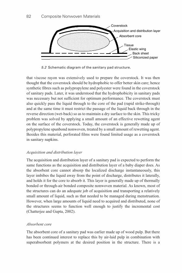
82 Composite Nonwoven Materials
that viscose rayon was extensively used to prepare the coverstock. It was then thought that the coverstock should be hydrophobic to offer better skin care; hence synthetic fi bres such as polypropylene and polyester were found in the coverstock of sanitary pads. Later, it was understood that the hydrophobicity in sanitary pads was necessary but not suffi cient for optimum performance. The coverstock must also quickly pass the liquid through to the core of the pad (rapid strike- through) and at the same time it must restrict the passage of the liquid back through in the reverse direction (wet- back) so as to maintain a dry surface to the skin. This tricky problem was solved by applying a small amount of an effective rewetting agent on the surface of the coverstock. Today, the coverstock is generally made up of polypropylene spunbond nonwoven, treated by a small amount of rewetting agent. Besides this material, perforated fi lms were found limited usage as a coverstock in sanitary napkins.
Acquisition and distribution layer
The acquisition and distribution layer of a sanitary pad is expected to perform the same functions as the acquisition and distribution layer of a baby diaper does. As the absorbent core cannot absorp the localized discharge instantaneously, this layer imbibes the liquid away from the point of discharge, distributes it laterally, and holds it for the core to absorb it. This layer is generally made up of thermally bonded or through- air bonded composite nonwoven material. As known, most of the structures can do an adequate job of acquisition and transporting a relatively small amount of liquid, such as that needed to be managed during menstruation. However, when large amounts of liquid need to acquired and distributed, none of the structures seems to function well enough to justify the incremental cost (Chatterjee and Gupta, 2002).
Absorbent core
The absorbent core of a sanitary pad was earlier made up of wood pulp. But there has been continued interest to replace this by air- laid pulp in combination with superabsorbent polymers at the desired position in the structure. There is a
5.2 Schematic diagram of the sanitary pad structure.
Absorbent hygiene products 83
signifi cant use of superabsorbent polymer in many brands of sanitary pads. In many cases, the solid polymer in powder form is lightly affi xed to a tissue. This composite layer is then inserted between the back sheet and the absorbent pulp pad or in a lower layer of the pad. The position of the superabsorbent polymer is very important in a sense that it must absorb and hold liquid, but must not retard the fl ow- in of the subsequent additional liquid by blocking the pores of the structure due to swelling.
Back sheet
The back sheet is an impermeable thin fi lm or barrier fabric that prevents leakage. It is a breathable but liquid impervious fi lm and generally made up of polyethylene.
5.4.3 Recent developments
In recent years, the feminine hygiene market has been characterized by lighter, thinner and more absorbent products, leading to greater wearer comfort. The arrival of the short fi bre air- laid nonwoven absorbent core has revolutionized feminine hygiene products during the last decade. This means that nowadays more nonwoven material is being used per product unit. Like baby diapers, the superabsorbent polymer has been extensively used in making lighter, thinner and more absorbent sanitary pads. Das et al. (2008) reported developing a series of high absorbent light- weight sanitary pads where the absorbent core was made up of super absorbent fi bres and viscose rayon fi bres. They tested the absorption behaviour by using saline water as a test liquid. It was observed that the saturation absorption of the core followed a linear relationship with the percentage of superabsorbent fi bres in the core and the basis weight of the core.
In a patent, Trillas et al. (2007) reported on development of a plasma- treated nonwoven fabric for the use in feminine hygiene products. It was claimed that it is possible to control the addition of hydrophilic and hydrophobic groups in the fabric by controlling the plasma generation and application. Chi (2007) made a patent disclosure on a hygiene product with far infrared anions. This product was made of an outer leak- proof layer, a middle absorbent layer made of water absorbent material, and an internal contact layer made of water penetrating material. The fi bres of the materials were attached with a constituent capable of releasing far infrared anions to achieve a sanitary anti- bacterial effect and a nursing care condition. Bentz (2007) disclosed a hygiene article for use in sanitary pads, which was developed from a textile fabric having a multiplicity of fi bres onto which microencapsules, including materials in which a phase transition from solid to liquid and vice- versa took place in a temperature range from 15 °C to 40 °C, were applied.
Digiacomantonio et al. (2007) reported a novel absorbent article, which was made of three layers: a body- facing surface, an absorbent structure, and a garment-
84 Composite Nonwoven Materials
facing structure. The structure was comprised of a central liquid acquisition system, a fi rst visually discernible lateral zone situated on one side of the central zone, and a second visually discernible lateral zone situated on the opposite side of the central zone. Kim et al. (2001) reported an absorbent article with fl uid intake intensifi er which was made of a low density air- laid nonwoven. Harriz (2003) developed a super absorbent composite for the use in personal hygiene products which was composed of a nonwoven core with super absorbent polymer uniformly distributed throughout the thickness of the core and bonded to the core with an adhesive.
5.5 Adult incontinence pads
5.5.1 Functions
The adult incontinence pad is another important disposable absorbent hygiene product. It’s functions are to (1) absorb and retain wearer’s urine, (2) isolate wetness from wearer’s skin, (3) contain faeces, and (4) isolate urine and faeces from the wearer’s environment. These functions should be accompanied by providing a feel of maximum comfort, having an aesthetic appearance, preventing odour, and staying in place.
5.5.2 Components
The current adult incontinence pads are composites consisting of a variety of different materials, some in the form of pre- formed webs, to create a series of functional layers to achieve the aforesaid functions. As stated by White (2003), the products designated for management of heavy adult incontinence were based on the design and manufacturing technology of baby diapers, while feminine hygiene product developments were used in the case of light incontinence products. In both cases, it is important to remember that the adult incontinence products were required to deal with larger volumes of liquid and yet handle them in an effective way. Nevertheless, the building blocks of adult incontinence pads are made up of coverstock, acquisition and distribution layer, absorbent core, and back sheet. The function and composition of each of these four components are discussed below.
Coverstock
This is the top sheet layer of adult incontinence pads which can be a pre- formed nonwoven carded fi bre web or a continuous fi lament web or a plastic fi lm with carefully designed holes. The spunlaid thermal bonded polypropylene nonwovens have become the material of choice for use in coverstock application. Also, the spunlaid composites are favourably used in making the coverstock of baby diapers.
Absorbent hygiene products 85
Acquisition and distribution layer
The acquisition and distribution layer of an adult incontinence pad is a nonwoven material which is made up of synthetic fi bres or a modifi ed cellulosic fi bre layer. In fact, there are two different approaches taken to create an effective acquisition and distribution layer in order to provide a temporary holding of the liquid transmitted through the topsheet, keeping the skin contact surface of that layer dry and then effectively distributing the liquid into the absorbent core. One type of structure is based on the use of modifi ed cellulosic fi bres to create a reduced swelling and open pore structure that provides temporary storage capacity. This type of web is often coupled with an open structure highloft nonwoven to provide fl uid distribution. The other approach is to use a low density, through- air bonded nonwoven that can provide both functional requirements. Note that, whichever approach is taken, the coverstock and acquisition and distribution layer must work in concert to ensure dryness of the surface of the coverstock.
Absorbent core
This is a liquid storage layer that is made up of cellulose fl uff pulp and superabsorbent polymer. The use of superabsorbent polymer results in a drier skin that minimizes rash and irritation and provides greater comfort and personal hygiene. This also results in lowering the amount of fl uff pulp required to produce a satisfactory storage core to be signifi cantly reduced, which in turn offers a signifi cantly thinner product. Sometimes powders are added in the absorbent core for odour control.
Back sheet
This is a backing containment layer that is normally a plastic fi lm, either breathable or not. Sometimes a nonwoven layer is added to the external surface of the fi lm in order to improve aesthetics and impart a cloth- like feel to the external surface of the product.
5.5.3 Recent developments
A well- designed engineered nonwoven structure for the use in disposable adult incontinence products for incontinence management has been a rapidly growing area of interest among the nonwoven scientists and researchers worldwide. As stated by White (2003), there has been a major effort seen in the past few years to develop absorbent air- laid products by using M&J Fibretech and DanWebforming systems and combining wood pulp, synthetic fi bre, binder fi bres and granular superabsorbent polymer into a multilayer composite material. Also, attempts were seen to insert pre- formed web material into the structure of adult incontinence products. Further, multiforming heads were used to develop a structure comprising
86 Composite Nonwoven Materials
of different fi bres in different layers that could be ultimately combined with pre- formed webs produced by other technologies. This led the way to the production of multi- process and multi- layered composite products where specifi c performance characteristics might be built into each layer. Rahbaran et al. (2011) made a patent disclosure of a highly absorbent reusable pad for use in incontinence and hygiene products, wherein a nonwoven fabric containing a blend of man- made cellulose fi bres and synthetic fi bres with multi- lobal cross- section was used.
5.6 Conclusion and future trends
The key issues associated with absorbent hygiene products are related to dermatitis and disposability. The interaction between skin and absorbent hygiene products is reported in detail by Runeman (2008). It is learnt that the skin problems due to the use of these products are mostly associated with the climate or chafi ng discomfort that would lead to irritant contact dermatitis and eventually superfi cial skin infections. It is suggested that individuals with frail, sensitive skin or with skin diseases should preferably use high- quality products, equipped with superabsorbent polymers and water- vapour-permeable backsheets, to minimize the risk of skin complications. There is always strong demand for absorbent hygiene products to show biodegradability. The air- laid nonwovens offer possibilities for biodegradable air- laid, which is a big plus over many nonwovens (Mango, 2005). There are some products in the market which are said to be biodegradable and of biological origin, compared to many leading branded products with a very high oil- based content. Also, the fi bre- producing industry is heavily active in research on new fi bre types that are derived from renewable sources, such as polylactic acid was derived from corn or other vegetable starches. Besides dermatitis and disposability issues, environmental considerations, including fl ushability concern, is also growing. The modern hygiene products are expected to show great fl ushability to disintegrate as quickly as possible. Despite these issues and concerns, the marketers of absorbent hygiene products continue to focus on product innovation to woo customers, thus creating a highly competitive global market. As predicted by Freedonia Group in a market research report (2011), the personal hygiene market will continue to account for the single largest share of nonwoven demand in 2015. The use of these goods will expand the fastest in developing areas, fuelled by growth in population and a high standard of living. The demand for further thinner, lighter and more absorbent products, leading to greater wearer comfort is increasing. In this respect, one can expect further development and application of pre- formed multi- layer and multi- component composite structures in baby diapers, sanitary pads, and adult incontinence pads. Further, in order to maximize the effi ciency and effectiveness of the composites, a synergy between the individual layers assigned to specifi c tasks for working coherently together is required. In doing so, they are expected to deliver a performance that is far superior to that of the individual layers in isolation.
Absorbent hygiene products 87
5.7 Sources of further information and advice
Absorbent hygiene products are composites of nonwoven and allied materials. A very good source of information on the technical developments of these products can be patents as a large number of excellent innovations are found to be reported in this form. Yet the rising demand for further thinner, lighter, more absorbent and more comfortable hygiene products may pave the way for newer combinations of nonwovens in order to create a variety of disposable absorbent products. One may therefore like to watch for newer patents reporting on further interesting innovations on these products. Besides, there are several trade journals which are continually publishing latest information on absorbent hygiene products. They include Nonwoven Industry , Nonwovens World , Nonwoven Markets , Nonwovens Reports International , etc. These journals can therefore be of interest to obtain the latest information on market scenario and developments of absorbent hygiene products. Further, the publications of professional bodies such as INDA and EDANA and research scientists worldwide can also be the source of further information on absorbent hygiene products.
5.8 References
Allan , G. G. ( 2005 ) ‘ The movement of liquids through complex nonwoven structures ’, Nonwovens Industry , December , 62 – 65 .
Amos , D. T. , Chong Conklin , B. E. , Statham , A. S. , Svarovsky , M. J. , and Wood , L. E. (3M Innovative Properties Company) ( 2012 ). Antimicrobial disposable absorbent articles , WO Patent 037065 A1 , 22 - Mar - 2012 .
Barge , P. , Landreth , M. , and Carter , N. M. ( 2004 ). Liquid acquisition layer with caliper recovery and the method for producing the same , US Patent 0230173 A1 , 18 - Nov - 2004 .
Bentz , M. ( 2007 ). Hygiene article , US Patent 006421 A1 , 18 - Jan - 2007 . Chatterjee , P. K. and Gupta , B. S. ( 2002 ) Absorbent Technology , Amsterdam , Elsevier
Science B. V. Chi , K.-M. ( 2007 ). Hygiene product with far infrared anions , US Patent 0197989 A1 , 09 -
Jan - 2007 . Coronado , N. , Ruiz , F. , and Santisteban , J. (Polymer Group Inc.) ( 2004 ). Leight weight,
cloth- like nonwoven laminate and articles , WO Patent 092470 A2 , 28 - Oct - 2004 . Das , A. , Kothari , V. K. , Makhija , S. , and Avyaya , K. ( 2008 ), ‘ Development of high-
absorbent light- weight sanitary pad ’, Journal of Applied Polymer Science , 107 : 1466 – 1470 .
Dharmadhikary , R. , Kronfeld , A. M. , Chen , P. Z. , and Meikle , G. D. (Ahlstorm Windsor Locks LLC) ( 2004 ). Ethylene oxide sterilizable low cost nonwoven laminates with high wet peel strength and improved barrier properties , WO Patent 054801 A1 , 01 - Jul - 2004 .
Digiacomantonio , M. , Ecker , C. , Gagliardi , I. , Partenza , V. , and Veglio , P. A. (Procter & Gamble Company) ( 2007 ). Absorbent article having nonwoven lateral zones , EP 1842513A1, 10 - Oct - 2007 .
Fleissner , G. (Fleissner GmbH) ( 2001 ). Method and device for production of composite nonwoven fabrics by means of hydrodynamic needling , US Patent 6836938 , 04 - Jan - 2005 .
Freedonia Group, USA ( 2011 ). World Nonwovens Industry Study with Forecasts for 2015 and 2020 in 19 countries .
88 Composite Nonwoven Materials
Harriz , J. M. (Tyco Healthcare Retail Services AG) ( 2003 ). Process for making a super absorbent polymer- impregnated nonwoven absorbent core for personal hygiene products , US Patent 0129915 A1 , 10 - Jul - 2003 .
Isele , O. E. A. and Chhabra , R. (Procter & Gamble Company) ( 2005 ). Hygiene articles containing nanofi bres , WO Patent 004767 A2 , 20 - Jan - 2005 .
Kim , H. B. , Eun , J. K. , Hwang , E. Y. , and Kim , D. H. ( 2001 ). Absorbent article with fl uid intake intensifi er , US Patent 0044610 A1 , 22 - Nov - 2001 .
Koczab , J.-P. (SCA Hygiene Products) ( 2002 ). Composite nonwoven material and its application to any absorbent article of hygiene , US Patent 6452062 , 17 - Sep - 2002 .
Luo , M. (Weyerhaeuser Co.) ( 2009 ). Lyocell nonwoven webs , WO Patent 123889 A2 , 25 - Mar - 2009 .
Mango , P. ( 2005 ), ‘ Airlaid: State of the industry ’, Nonwovens Industry , October 2005 . Martin , K. E. (E. I. Du Pont De Nemours and Company) ( 2003 ). Elastic nonwoven sheet ,
WO Patent 089714 A1 , 20 - Oct - 2010 . Nguyen , H. M. (Invista North America S. A. R. L.) ( 2006 ). Extensible fi bres, method for
their production and use , WO Patent 031625 A2 , 23 - Mar - 2006 . Rahbaran , S. , Cottenden , A. , Santamartavilele , R. , Russel , S. J. , and Ningtao , M. (Lenzing
AG) ( 2011 ). Highly absorbent reusable pads, a process for their manufacture and their use in reusable hygiene products , WO Patent 097661 A1 , 18 - Aug - 2011 .
Runeman , B. ( 2008 ) ‘ Skin interaction with absorbent hygiene products ’, Clinics in Dermatology , 26 , 45 – 51 .
Seneviratne, C. M. W. (Senevens International Ltd.) ( 2009 ). Nonwoven biodegradable hygiene product , WO Patent 036483 A1 , 19 - Sep - 2007 .
Sun , C. (Q.), Zhang , D. , and Wadsworth , L. C. ( 2002 ) ‘ Development of innovative cotton- surfaced nonwoven laminates ’, Journal of Industrial Textiles , 31 , 179 – 187 .
Trillas , X. C. , Pano , R. G. , and Riera , R. G. ( 2007 ). Process to produce nonwoven fabrics with totally or partially hydrophilic areas and hydrophobic areas , US Patent 0117490 A1 , 08 - Dec - 2005 .
Udengaard , B. , Hummelgaard , L. K. , Reichardt , N. A. , and Springob , C. (Procter & Gamble Company) ( 2010 ). Absorbent article with barrier component , WO Patent 151410 A1 , 29 - Dec - 2010 .
White , C. F. ( 2003 ), ‘ Proceedings of the Institution of Mechanical Engineers, Part H ’, Journal of Engineering in Medicine , 217 , 243 – 251 .
Wood , L. E. , Statham , A. , Porbeni , F. E. , Maki , R. J. , Yarwood , J. M. , et al. (3M Innovative Properties Company) ( 2009 ). Antimicrobial disposable absorbent articles , WO Patent 126512 A2 , 15 - Oct - 2009 .
Wu , P. C. , Jones , G. , Shelley , C. , and Woelfl i , B. ( 2007 ) ‘ Novel microporous fi lms and their composites ’, Journal of Engineered Fibres and Fabrics , 2 , 49 – 59 .
89
© 2014 Woodhead Publishing Limited
6 Composite nonwovens in wipes
R. S. RENGASAMY, Indian Institute of Technology Delhi, India
DOI: 10.1533/9780857097750.89
Abstract: Dry and wet wipes are widely used in personal care, household and industrial applications, and the majority of wipes are made from nonwovens. The selection of fi bre(s), technology of web formation and bonding of fi bres to make nonwovens, and surface texturing of them, are important in achieving the desired properties of wiping products. This chapter contains a brief introduction to the types of wipes, the technology used in web formation and bonding of fi bres, and surface texturing of wipes. Various processes, products and their salient features pertaining to hydroentangled and thermobonded composite nonwoven wipes produced from carded, airlaid pulp, wetlaid pulp, spunbonded, spunbond-meltblown-spunbond (SMS), Coform and elastic layers are discussed. The chapter also outlines recent developments and future trends in the development of wipes from bio- degradable and recycled fi bres, and fl ushable wipes.
Key words: airlaid, carded, cleanroom, hydroentangled, ion trigger, spunbond, surface texturing, thermobonded, wetlaid.
6.1 Introduction
To wipe is defi ned as ‘to rub with’ or ‘something soft for cleaning’ or ‘to clean’ (Merriam-Webster). Wipes can be a paper, tissue or nonwoven and are subjected to light rubbing or friction in order to remove dirt or liquid from the surface. Consumers want wipes to absorb, retain or release dust or liquid on demand. One of the main benefi ts that wipes provide is convenience. A wipe is quicker and easier to use than the alternative of dispensing a liquid and using another cloth or paper towel to clean or remove the liquid (Sahu 2012).
Wipes can be categorized as disposable and semi- durable wipes. Disposable wipes are disposed of after single use; hence, there is no need to worry about cross- contamination. Wipes can be broadly classifi ed into dry wipes and wet wipes (containing lotion) according to the types of applications. Wipes are produced from wovens, nonwovens, composite nonwovens and fl ock of fi bres, etc. Based on the end user applications, wipes can be classifi ed into consumer wipes (personal care including baby wipes, household/home cleaning) and industrial wipes (general purpose and speciality). According to EDANA, industrial wipes are: ‘disposable nonwoven products used for a variety of applications in industry ranging from heavy duty cleaning to fi ne polishing’, for which the wipes are single use products or limited use products that become waste material after use (edana.org).
Wipes started at the bottom or more precisely, the baby’s bottom. Still, baby wipes constitute a major segment of wipes; but the share is declining with the
90 Composite Nonwoven Materials
infl ux of many wipes being introduced in the market for specifi c applications in the personal care, household and industrial segments. A large number of wipes made from nonwovens cater to personal care such as toddler toilet care, cosmetic (deodorant, facial), adult moist toilet tissue, adult incontinent/bath wipes, feminine hygiene wipes and healthcare wipes, etc.
Household wipes include regular wet and dry fl oor wipes, cleaning/disinfectant wipes, kitchen wipes, mop pads, dishwashing, apparel care, furniture cleaning, glass wipes, food service and automotive care wipes, etc. More importantly, the electrostatic wipes constitute 38% of value of global sales of home care wipes (Bell 2011). Nonwovens are electrically treated to enhance particle attraction to improve the effi ciency of picking up dust and dirt (Keck et al. 2006). Industrial wipes are used in the automotive industry, machine/instrument cleaning/degreasing/surface preparation, the electrostatic, optical, printing and electronics industries, and clean room applications, etc.
Currently, the share of personal care, household and industrial wipe products in the wipes market are about 62%, 23% and 15% respectively. Baby wipes accounted for 63% of personal care wipes sales in 2010 (Bell 2011). The market for personal care, household and industrial wipes were growing at 16%, 8% and 13% respectively in the year 2010. As per the EDANA’s report in 2010, the total wipes deliveries in 2010 amounted to 283,058 tonnes as compared to 250,356 tonnes in 2009. Between 2007 and 2017 the consumer wipes market is forecast to increase from over $7.6 billion to $12.6 billion, with an annual growth rate of 5.2%. In the same period, the industrial wipes market is expected to increase from about $1.8 billion to $3.2 billion. The leading companies with brands that employ wipes include Unilever, Procter & Gamble, Kimberly-Clark, Johnson and Johnson, S C Johnson, Colgate-Palmolive, Kao Corporation, Henkel, Reckitt & Benckiser and Clorox.
6.2 Materials in wipes
The most important requirement for a wipe is rapid absorbency and the ability to pick up dirt. Wipes designed to pick up aqueous liquid are made from hydrophilic materials such as rayon, wood pulp and cotton. Wipes to pick up oil- based liquids are made from hydrophobic fi bres such as polypropylene and polyester, etc. Some wipes are designed to pick up both these liquids. The materials used in wipes vary depending on the applications and are petroleum- based fi bres (polyester and polypropylene), cellulose- based fi bres (wood pulp, fl uff pulp, specialty paper pulp, viscose rayon, Lyocel, acetate, Tencel and cotton), splittable bicomponent fi bres, blends of cellulosic and synthetic fi bres and polylactic acid, latex binders. The technical wipes used in the aerospace, automotive, optical and electronics industries and other special wipes are especially made from splittable bicomponent fi bres.
The majority of wipes are made from blends of polyester and viscose fi bres/wood pulp. The cellulose fi bres/wood pulps provide high absorbency
Composite nonwovens in wipes 91
and are biodegradable. The synthetic fi bres provide strength, abrasion resistance, and solvent resistance; and can be treated with antimicrobial and static dissi-pation fi nishes for certain applications. The microfi bres in wipes provide soft handle, fl exibility and smooth surface; and the bicomponent fi bres give added functionality.
Wipes for certain applications require incorporation of fi nishing or ingredients such as biocides (antimicrobial, mildemicide, antiseptic, disinfectant sanitizer, germicide, algaecide, preservative) abrasive particles, perfumes, alcohol, and activated carbon, etc. The anti- microbial nonwoven wipe has a nonwoven substrate comprised of a non- ionic binder and a cationic disinfectant. When water is introduced into the wipe, the disinfectant is readily released from the wipe. Alternately, a nonwoven with a non- ionic binder can be used along with a separate commercially available disinfecting or sanitizing solution (Ellis et al. 2011). For high absorbency, super absorbent fi bres are used. For heavy duty cleaning applications, wipes are incorporated with abrasive particles such as aluminium oxide, metal carbides, borides, and nitrides, fused alumina zirconium, sol gel abrasive particles and minerals. A scrubbing wipe is made by printing a texture layer on to one or both surfaces of a nonwoven layer. The texture layer is a non- crosslinked and abrasive resin- based material. The texture layer does not cover the entire surface of the substrate and protrude about 50 microns from the substrate surface to have a distinct scrubbiness (Johnson and Lindquist 2010).
6.3 Wet wipes
Wet wipes are pre- moistened with solution, using either single or multi compounds. Baby wipes are used to cleanse the sensitive skin of infants. They contain saturated solutions such as gentle cleansing ingredients and alcohols. Cleansing pads for preventing infection may be soaked with water, alcohol and other active ingredients for a specifi c intended use. Anti- acne pads usually contain salicylic acid, vitamins, menthol and other compounds.
A customer survey conducted by Dow has revealed that the wet wipes currently available in the market are yet to meet the following criteria (Anonymous 2008, pp. 16–22):
• wipes that stay wet longer; • more consistent lotion loading; • better dirt removal; • more bulk and softer touch; • environmental friendly wipes such as fl ushable and biodegradable; • multifunctionality such as clean and protect, clean and moisturise and clean
and cool; • substrates free of non-desirable residuals; • lotions that do not extract non-desirable residuals;
92 Composite Nonwoven Materials
• better entrapment and killing of microbes; • wipes that leave a surface shiny; • wipes that won’t scratch delicate surfaces.
In wet wipes, the substrates play an important role in deciding the following characteristics and properties: sorption rate and capacity, rheology, hand, strength, extensibility, thickness, brightness, texture, abrasiveness and disposability (Robinson, 2005). Sometimes formaldehyde is used to improve the bactericidal properties of wet wipes; however there is evidence of the carcinogenic potential of formaldehydes. In Europe, a maximum authorized limit of 0.2% free formaldehyde is well established for the lotions of personal care wet wipes under a cosmetics directive (Anonymous 2011a).
6.4 Web forming technologies for wipes
Fibres are laid in the form of a web or sheet using carding, airlaid, wetlaid, spunbond and meltblown technologies. Hydroentangling, thermal bonding (calendaring rollers and hot air oven), needlepunching and stitch bonding are used to bond the fi bres in webs. For thermal bonding, the web must contain some proportion of low melting fi bres. The technologies of web forming and bonding affect the functional properties and cost of wipes. In the wipes market, hydroentangled (referred to in the trade as ‘spunlaced’) products made from both carded and airlaid webs constitute 49%, airlaid- thermal and airlaid- chemical bonded (referred to in the trade as ‘airlaid’) is about 26% and the rest (needlepunched, wetlaid- chemical/binder fi bre bonded, and spunlaid- calendared and composite nonwovens that combines webs made using different technologies) are about 25%.
6.4.1 Carded nonwoven
Viscose rayon, Tencel, cotton, polypropylene and polyester fi bres with long cut lengths are used in carding. Prior to carding, fi bres are opened and blended. The fi bres in carded webs are more oriented in machine direction. In order to reduce the ratio of strength in machine and cross direction, webs are cross laid. The webs are bonded by needlepunching or thermal bonding or hydroentangling or stitch bonding. Hydroentangled carded nonwovens have high softness, drape, bulkiness and resilience. Heavy duty industrial and household wipes are made from viscose rayon or Lyocell or synthetic fi bres or blends through carding and needling. Needlepunched wipes can store large volumes of liquid/lotion compared to hydroentangled wipes. Pre- moistened wipes containing anti- bacterial soap used in post- operative care are needled structures. Needled structures are also used for polishing cloth.
Multi- layer carded webs are stitch bonded using Malivilies technology. Absorbing and polishing cloths are made from Malivilies fabrics. Theses fabrics
Composite nonwovens in wipes 93
are composed entirely of fi bres and no fi laments. Viscose, reclaimed fi bres, polypropylene and polyester fi bres are used.
6.4.2 Airlaid nonwoven
In the airlaid process, woodpulp available in rolled sheet form is converted into fi bres in hammer mills. The woodpulp fi bres are transported by conveyor to the forming head drum of an airlaid unit. When the airlaid webs are to be thermal bonded, melt fi bres are also supplied through bale opener and weight metering systems. When there are two types of non- woodpulp fi bres required to be mixed with woodpulp (example: two types of melting fi bres, short length polyester, polypropylene or bicomponent fi bres), then two opening lines feed these fi bres to the forming head drum. The perforated drum in the forming head rotates and suction is applied inside the drum. The fi bres adhered to the surface of the drum are transported with vertical air fl ow produced by a vacuum inside the suction box to the web formation belt, where they are deposited. The products weight range is 10–600 g/m 2 (Watzl 2006).
Airlaid webs are bonded by thermal bonding or chemical (latex) bonding or hydroentangling. Latex bonding is the most common bonding process. In latex bonding process, the top surface of the web is sprayed with chemicals and dried, and then this sequence is repeated for the bottom surface of the web. In the thermobonding process, the airlaid web containing the melt fi bres are heated by fl ow of hot air in a belt oven until they start to melt and bond with the loose pulp fi bres. This process is clean and energy- saving as compared to the latex bonding. However, the surfaces of thermobonded airlaid web still contain loose pulp fi bres that form dusts during production and use of the web. Further, the thermal bonded airlaid product does not have enough strength. To avoid this, the surfaces are impregnated with lightweight latex foam using a foam padder. Alternatively, only the surfaces are padded with foam, leaving the inner layer as bulky and absorbent. Both the thermal and chemical bonded products are not preferred for baby and cosmetic wipes, and these are used mainly in household and surface care applications.
Airlaid nonwovens are isotropic, lofty, have high porosity (95–99%), high absorbency and wicking rate due to the presence of woodpulp fi bres, softer handle, good resiliency and adequate tensile strength. Hence, some wipe manufacturers prefer airlaid- thermal bonded over carded- spunlaced materials due to a softer, spongier feel and lower production cost (Bitz 2002).
Hydroentangled- airlaid web offers textile- like handle (softness and fl exibility) and strength to wipes and in most cases absorbent characteristics (rapid absorption and retention of liquid). Airlaid- spunlaced nonwovens are softer, spongier and cheaper than the carded- spunlaced nonwovens, hence are more suitable for wiping products (Bitz 2002). With increasing water jet pressure during hydroentangling, the fi bre consolidation improves, thus enhancing the strength; however, the shear
94 Composite Nonwoven Materials
modulus remains more or less the same, thus retaining the softness. Further, the hydroentangling of web containing splittable bicomponent fi bres (polyethylene on the surface and polypropylene in the core of the fi bre) gives added benefi t of very soft feel as the fi bres split into microfi bres.
Fusible fi bres used for thermal bonding are costlier and the fused regions present on the surface of wipes give a harder feel to the skin. Because of these reasons, in the last few years, the hydroentangling is increasingly substituting the airlaid- thermal bonded nonwovens, especially in the personal care wipes market. In the impregnated wipe market (wet wipes), both the airlaid- hydroentangled and airlaid- thermal bonded are present. Multiple layers of webs (carded, airlaid, spunlaid) having different characteristics such as softness, absorbency and strength are combined using hydroentangling. Because of the advantages of hydroentangling, many integrated production lines comprising carding, airlaid and hydroentangling units are manufactured.
6.4.3 Wetlaid nonwoven
The wetlaid technology has the capability to process a wide range of fi bres such as very short fi bres and brittle fi bres, incorporating binders and particulates in the structure. Wetlaids are bonded using hydroentangling or binder fi bres. Premium Nice-Pak (R) , a thin wipe, is made from a mix of woodpulp fi bres using wetlaid and hydroentangling, whereas economy wipes are wetlaid- thermobonded (Wilson 2003). In future, the demand for fl ushable- dispersible wipes will grow; the wetlaid will play a signifi cant role in this segment as the dispersibility of used toilet wipes requires incorporation of very short fi bres.
6.4.4 Spunlaid nonwoven
The production speed of spunbond is very high, about 600 m/min. The spunbond process requires a heavy investment cost, but the cheaper polymer chips and direct conversion from them into fi bres reduce the manufacturing cost considerably. Fewer fi bres are required or thinner web can be made for a given strength of product, thus saving on production costs. Recycled polymers which are much cheaper can be processed using the spunbond method. The spunbonded products are the strongest and have better dimensional stability, but the spunbond process is least fl exible in the sense that it can only be used for thermoplastic fi bres. Products containing cellulose fi bres cannot be made. The spunbond wiping products are stiffer.
Spunlaid nonwovens have very high strength in machine and cross directions compared to other nonwovens. The spunlaid nonwovens are usually calendered. Calendering compresses the web and generates melted fi bre intersections which increases stiffness of webs. For personal care applications, they are not suitable. The recent trend is to combine spunbond with hydroentangling. The spunlacing of
Composite nonwovens in wipes 95
spunbonded fabrics does not fuse fi bres and stiffen the fabric because it bonds the individual fi laments. Hydroentangling the calendered spunbond nonwovens also gives a softer feel compared to traditional spunbond- calendered. In this case, the temperature during calendaring can be reduced as further bonding is done using hydroentangling. The benefi t is energy saving.
Rieter offers the ‘Perfobond 3000’ spunlaid system for web forming and the web bonding can be done with either a calender or hydroentanglement by ‘Jetlace 3000’ (Wilson 2003). The Rieter’s integrated system, ‘Perfojet’ combines the spunlaid and hydroentanglement systems. Other integrated spunlaid- hydroentanglement systems used to produce fabrics include Freudenberg’s Evolon (R) from splittable bicomponent fi laments and the Polymer Group Inc.’s Spinlace™ for single component fi laments.
Oil sorbent pads made by using meltblown technology constitute an important category of spunlaid nonwovens. Single layer webs are sonic bonded to improve strength and durability. To remove oil spill on water bodies and also to clean oil and grease in kitchens, on fl oors, walkways and machines, polyolefi n fi bres (polypropylene and polyethylene) are used. Meltblown polypropylene webs are also thermal calendered to produce oil sorbent wipes. Several commercial wipes are manufactured using this nonwoven material.
The oil sorption and retention capacities of the wipes are important for oil spill cleanup. The surface energy of polypropylene is slightly higher than the surface tension of many oils and much below the surface tension of water. Hence, polypropylene is highly oleophilic and hydrophobic making it suitable for oil spill removal. The oil retention capacity (g of oil/g of fi bres) of the oil absorbing pads must be very high to reduce material consumption. The meltblown structures have very fi ne pores with narrow distribution, this improves the sorption rate and sorption capacity of oil- sorbents.
Hydroentangled spunlaid bicomponent fi bre nonwovens are suitable for cleanroom wiping application. The combination of polymers and their arrangement in fi bre cross section must be considered in developing such wipes. Evolon (R) fabrics are spunlaid produced from splittable bicomponent fi laments (16 segmented pie, polyester and nylon66 in 65%/35% proportion) of about 2 d.tex, which are hydroentangled at up to 400 bar to split the fi laments into multiple microfi laments about 0.09–0.13 dtex. These fabrics have very high fi lament surface area, softness, strength and abrasion resistance. These have potential applications in cleanroom wipes besides the current applications in sportswear and active wear (Anand et al. 2007).
6.5 Web bonding processes for wipes
6.5.1 Needlepunching
The production speed of needlepunching is very low. Lightweight wipes cannot be produced using needlepunching. The high draft required during needling alters
96 Composite Nonwoven Materials
the strength ratios in the principal directions of wipe. Needling generates broken fi bres in the web that results in strength reduction and also gives the appearance of a rough surface and needle spot marks which are not preferred for personal care wipes.
6.5.2 Chemical bonding
Water- born latex is mostly used as a chemical binder which is applied about 5–30% by weight. Saturation, foam, spray, print and powder are methods of application to the nonwovens. Chemical binders in wipes have low skin tolerances and gives slight odours. The process is not environmentally friendly, hence they are not preferred for personal care wipes. Abrasive pads are made by bonding abrasive particulates to the nonwovens using latex.
6.5.3 Thermobonding
The high price of melt fi bres adds to the cost of wipes. A blend of synthetic melting fi bres with natural fi bres results in low strength to the wiping product. All natural or cellulosic fi bre wipes cannot be produced using thermobonding.
6.5.4 Hydroentangling
The production speed of a hydroentangling line is 200 to 400 m/min., about one- half of a spunbond line. In the case of apertured products, the production speed is limited to about 200 m/min. Hydroentanglement lines require higher investment costs than the carded- needling lines, but the hydroentangling process does not require a chemical binder or costly melting fi bres to bind the fi bres. All natural fi bre or cellulose fi bre products can be made. The draft given to the web during hydroentangling is very low so that the fi nal product does not undergo shrinkage, i.e., is dimensionally stable; and the strength ratio (MD/CD) is also low. Hydroentangled wipe products are smooth, soft and have textile- like handle and drape. They are stronger than the needlepunched, thermobonded and chemical bonded fabrics, and hence the wipes can be made thinner resulting in a saving in production costs. Spunlaced nonwovens are the leading substrates for personal care and household cleaning wipes. For facial cleaning wipes, all- staple spunlaced nonwovens are preferred.
6.6 Surface texturing of wipes
Wipes are apertured during hydroentangling on a cylinder with knuckles around which fi bres are directed and entangled. The support structures of web, especially the open area during hydroentangling, also affect the texture of fabrics. To create aperture on the surface of fabrics during hydroentanglement, a high water jet pressure is employed. Apertured fabrics have the appearance of woven fabrics
Composite nonwovens in wipes 97
(Evans and Shambelan 1970). Cleaning effectiveness is the most important factor among wipe users in selecting a wipe in the market. Incorporation of suitable patterns on wipes will improve their cleaning performance. A patent awarded to Polymer Group Inc., deals with imparting a three- dimensional image/pattern to nonwovens, resulting in a lofty material with a number of fi brous ends and loops extending beyond the surface of the recesses or pockets that improve the fabric’s: ability to collect low- viscosity contaminants present on skin (Chang and Edward 2004); thickness to hold chemicals and substrates; durability and scrubbing power (Wilson 2004). Floor wipes such as P & G’s Swiffer (R) are made with deep ridges and Clorox mops (Readymop) are quilted for better cleaning.
The Polymer Group Inc. (PGI) introduced Apex™ technology that creates complex embossed patterns on hydroentangled fabrics in the range 50–400 g/m 2 , such as Miratech (R) fabrics and derivatives, Mirastretch (R) for good elastic recovery and Miraguard (R) for barrier properties. Using appropriate patterns, the fabrics assume the appearance of woven and knitted textiles. Hydroentangling the fabrics on a laser imaged three- dimensionally patterned support surface transfers patterns onto the fabrics (Anand et al. 2007). To adjust the softness, shrinkage and drape of fabrics or to introduce elasticity to the fabrics or to improve the durability of pattern defi nition in the fabric, polymeric binders are added after hydroentanglement. To improve the durability of pattern defi nition in the fabric, blends containing fusible fi bres or woven scrims are also used (Black and Deleon 2004). Oran-B Brush-Ups (R) single- use swabs introduced by the Gillette Company are stretchable and textured; and used to clean the gums and teeth without toothpaste or water (Frederick 2004).
6.7 Composite nonwoven wipes
Nonwovens produced from each fi bre are unique in terms of their functional and durability characteristics. Wipes can be manufactured with improved functionality at lower cost using composite nonwovens having a mixture of fi bres and particulates or fi bres that differ in their chemistry or denier or shape in their structures. This may be obtained by layering the webs or homogeneous mixing of fi bres/particulates. In the case of layered structures, two or more nonwoven layers each having different fi bres or mix of fi bres made using different technologies are combined with or without wovens.
Composite nonwoven wipes have the capability to offer more overall functionality as compared to a plain nonwoven which has motivated the wipes’ manufacturers to spend most of their research and development efforts, including machinery upgrades and new plant investments, in composites. Through composites, the wipe manufacturers have the option of combining nearly any type of nonwoven together to produce products with distinguished features. The development of composite nonwoven wipes has provided the market with wipes having higher abrasion resistance, high wet and tear strength and
98 Composite Nonwoven Materials
increased barrier protection. Dual- surfaced composite nonwoven wipes having softer (needlepunched or spunlaced layer) and abrasive sides (meltblown layer) have improved bulk, are easier to handle and clean better than a plain product. Using composite nonwoven technology many advantages could be obtained ranging from improving the strength and durability of lightweight products (by having a spunbond or a meltblown layer in the composition), obtaining softness, absorption and strength (using a combination of fi brillated bicomponent fi bres, spunbonding the pulp and synthetic fi bres) and ability to form shapes (using an elastic fi lm as one of the layers).
The composite nonwoven route offers a never ending product range due its unlimited possibilities of combinations, lending the producers to expand into new market applications. Often in single layer wipes, when the basis weight is increased, the thickness, strength and bending stiffness increase and vice versa. It is diffi cult to isolate and manipulate the individual attributes as they are interdependent. In composite nonwovens, keeping a basis weight constant, the strength, softness, opacity, texture and stiffness can be varied by having layers differing in properties. The approach adapted by the machinery manufacturers in designing and fabricating the machines/lines to produce wipes with improved effi ciency of dirt removal, strength and softness, reduced cost and imparted with multifunctional characteristics through composite nonwovens, resulted in a reduction of manufacturing steps and development of products that substitutes two or more products. All these optimised the products in terms of cost and functionality with improved value addition.
6.8 Multi- fi bre composite nonwoven wipes
Viscose rayon blended with polyester or polypropylene or woodpulp are the common materials used in manufacturing of dry wipe products such as baby wipes, dusters, food service wipes and cleanroom wipes and also wet- fl oor wipes. The mixtures are airlaid, hydroentangled and the surfaces are apertured. The aperturing destabilizes and weaken the structure, especially the thinner fabrics. If the hydroentangling is done at low pressures (below 80 bar), then the structure is given either chemical or thermal bonding to stabilize and improve the strength of wipes. The binders usually increase the stiffness of wipes, so careful selection of binder type is important Viscose- pulp wipes used for household applications require application of 7–27% of binder on fabric to increases their durability in the wet state. The binder content can be reduced in the case of polyester–viscose blends. Point thermal bonding can be employed if polypropylene fi bres are blended.
Hydroentanglement at low pressure followed by point thermal bonding at reduced temperature and pressure than normally employed for thermal bonding alone would minimize the overall energy consumption and the resulting products are softer than the one that are only thermal bonded (Anand et al. 2007).
Composite nonwovens in wipes 99
Baby wipes are produced with 70:30 viscose rayon–polyester and 50:50 viscose rayon–woodpulp with a basis weight 55 g/m 2 . Food service wipes have 80:20 viscose rayon–polyester with basis weight 69–80 g/m 2 . The dusters have 75–91% polyester and 9–25% polypropylene with basis weight 30–65 g/m 2 . To improve dust pick up, embossed 3D patterns or mock piles surfaces are produced. Typical compositions of hydroentangled fl oor wipe are: 70:30 or 65:35 viscose rayon–polyester and the basis weight is about 90–100 g/m 2 . The mixture of viscose rayon and polypropylene can be pre- needled, followed by hot air thermal bonding which melts the polypropylene and binds the fi bres in the fabric. The proportion of polypropylene is around 15% for effective thermal bonding of fabric.
Cleanroom wipes are hydroentangled made from 100% polyester or blend with Lyocell or viscose rayon fi bres. Commercial wipes consist of airlaid polyester–viscose in 30:70 and 50:50 and other weight ratios. The important requirements of cleanroom wipes are extremely low linting, absorbent capacity and rate. It has been demonstrated that substantial reduction of lint generation can be achieved by employing higher than normal water jet pressure and slightly elevated jet- water temperature during hydroentanglement, which physically removes and particularly dissolves the removed particles. Water should not be re- circulated during hydroentangling. First, hydroentanglement is done on a fl at screen with six injectors operating with increasing pressures from the fi rst to last (7 bar to 140 bar) followed by fi nal hydroentanglement on a drum module with six injectors with increasing pressures from 31 bar to 140 bar which give best results in terms of reduced linting measured by particle sorbency quotient (Oathout 1994).
Sontara (R) fabrics produced by using DuPont’s patented technology are hydroentangled at very high jet pressure and are continuously washed during manufacturing to provide the wiping products extremely low- linting and exceptional cleaning ability. They are exceptionally strong even when wet and have high abrasion and tear resistance. Cleanroom wipes and surface preparation wipes used in aviation, automotive refi nishing, the food service, life sciences and the printing industry as well as a variety of maintenance and manufacturing applications are made by using this technology (McIntyre 2009).
Bamboo fi bres have high moisture- absorbing capacity and good anti- bacterial properties. Semi- durable wet wipes can develop unpleasant odours after use and the customer leaves the wipes to dry out as much as possible between uses or rinses them in a chemical such as bleach so that they remain hygienic during their lifetime. It has been shown in one patent that the anti- bacterial properties of bamboo fi bres help in containing the foul smell emanating from the used wet wipes. Thermobonded carded and cross lapped nonwovens having a mixture of 75:15:10 bamboo, polyester and thermobonding fi bres; 37.5:37.5:15:10 bamboo, viscose rayon, polyester and thermobonding fi bres; and latex bonded needlepunched nonwovens having 75:25 bamboo and polyester, were tested. The
100 Composite Nonwoven Materials
nonwovens containing bamboo needed less time to dry in an oven and better resistance to bacterial contamination as compared to latex bonded wet wipes made from 75:25 viscose and polyester fi bres (Rivera et al. 2009).
6.9 Multilayer composite latex bonded
nonwoven wipes
About 85% of pulp fi bre- based airlaid products are latex bonded and the rest are bonded by thermal and other bonding methods.
An airlaid pulp (one or two layers) placed between two surface layers made from rayon is latex bonded in a distinctive pattern. The binder solution (or emulsion) is sprayed onto the surface of the pulp layer and then sandwiched between the two rayon layers which are airlaid or carded. The combined structure is cured (thermally bonded) by hot air. The surface of the composite structure is apertured/patterned to improve the cleaning of dirt particles.
The major problem of latex bonding is the ability of the binder to penetrate into thick structures. The suction applied to the composite structure during sandwiching compacts it, preventing the binder reaching the interior of the pulp. To improve the fl ow of binder, a binder with low glass transition temperature is preferred. Many latex- based commercial wipes are available, mainly for industrial applications. Traditional latex binders give slight odour. Because of the limitation of latex binders, wipes manufacturers are switching over to the airlaid- hydroentangling process. With the availability of new types of binders, there is a possibility of the former process being revived in the future.
6.10 Hydroentangled (spunlaced) multilayer
composite nonwoven wipes
Wipes with required softness and drape along with absorbency, non- linting and non- collapsing (in the case of wet wipes) during use are made with composite nonwovens, wherein the pulp is airlaid on to carded web or spunlaid web. The composite is hydroentangled and requires no thermal or chemical bonding. The hydroentangled multilayer composite wipes available in the market are:
• carded- pulp- carded (CPC) • carded- pulp (CP) • carded- pulp- spunbond (CPS) • carded- spunbond-carded (CSC) • carded- spunbond (CS) • carded- net-carded (CNC) • carded-SMS (CSMS) • carded-SMS-carded (CSMSC) • carded- carded
Composite nonwovens in wipes 101
• spunbond- airlaid pulp (SP) • spunbond with wetlaid using pulp, glass and other short fi bres (SW) • spunbond- pulp- spunbond (SPS).
The pulp- based composite wipes are economically attractive because of the low cost of pulp. To improve strength and durability of wipes, the composites have either spunbond or woven scrim in the core. Hence, the hydroentangled CSC and CNC composites are used for industrial wiping products. The hydroentangled scrim- reinforced carded composite fabrics are also used in domestic wipes such as Procter & Gamble’s Swiffer (R) . The use of elastic net, elastomeric foam/fi laments/perforated fi lm in the core of CNC improves elasticity of fabrics which are suitable for stretchable wipes. The spunlaid- pulp composite nonwovens (SP and SPS) are stronger, durable and cheaper than carded- pulp composites and are targeted for industrial wipes. In three- layer nonwovens (CPC, CPS, SPS), some wipe manufacturers use cotton lint as the core layer in place of pulp.
Hydroentangled two- layer (SP) and multi- layer (SPS) wipes are made with spunlaid and pulp layers. Spunlaid (spunbond, meltblown and SMS) webs can be hydroentangled to introduce fi bre entanglement and then combined with a layer of 100% pulp or pulp blends with synthetic/viscose rayon to produce wipes. To introduce adequate fi bre entanglements in spunlaid structures and to avoid further bonding such as thermal calendering or chemical bonding, very high water pressures of 300–400 bars are required. The spunlaid- hydroentanglement lines have very high production speeds of up to 600 m/min in widths up to 5.4 m. Further, products made using a single layer of 10 g/m 2 and multi- layers with 400 g/m 2 can be made on a multi- drum module hydroentanglement installation with fi ve injectors followed by hydroentanglement on a fl at belt module with one or more injectors.
Spunlaid hydroentangled fabrics are free from thermo- fused regions introduced by calender bonding. This is advantageous in wipes as they would have comparatively high bulk and fl exibility, good tactile properties and high tear strength.
6.10.1 Carded- airlaid pulp- carded (CPC) wipes
The carded- airlaid pulp-carded (CPC) composites are used to make disposable wipes for both dry and wet applications. The CPC hydroentangled composites are made on a dedicated line consisting of two cards, one airlaid unit and a spunlacing unit. This three- layered composite has a core layer that contains either 100% pulp or pulp in blends with other short fi bres (3–15 mm). The core layer may be either sifted airlaid or wetlaid. In a sifted airlaid, the pulp fi bres are sifted through a coarse screen and deposited in the form of a sheet using suction below a forming wire. Additives such as odour control and super absorbent powders can be added during this stage. In the core layer, other short fi bres (such as polypropylene,
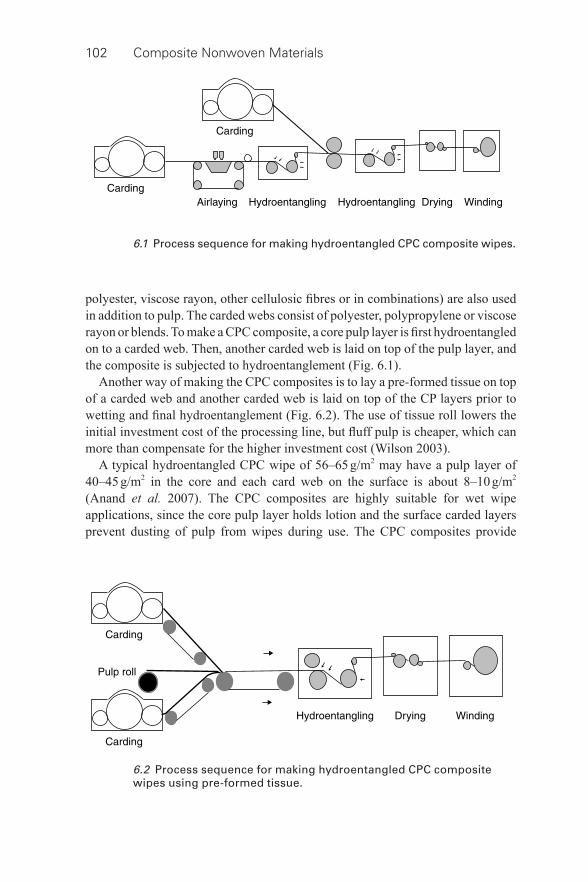
102 Composite Nonwoven Materials
polyester, viscose rayon, other cellulosic fi bres or in combinations) are also used in addition to pulp. The carded webs consist of polyester, polypropylene or viscose rayon or blends. To make a CPC composite, a core pulp layer is fi rst hydroentangled on to a carded web. Then, another carded web is laid on top of the pulp layer, and the composite is subjected to hydroentanglement ( Fig. 6.1 ).
Another way of making the CPC composites is to lay a pre- formed tissue on top of a carded web and another carded web is laid on top of the CP layers prior to wetting and fi nal hydroentanglement ( Fig. 6.2 ). The use of tissue roll lowers the initial investment cost of the processing line, but fl uff pulp is cheaper, which can more than compensate for the higher investment cost (Wilson 2003).
A typical hydroentangled CPC wipe of 56–65 g/m 2 may have a pulp layer of 40–45 g/m 2 in the core and each card web on the surface is about 8–10 g/m 2 (Anand et al. 2007). The CPC composites are highly suitable for wet wipe applications, since the core pulp layer holds lotion and the surface carded layers prevent dusting of pulp from wipes during use. The CPC composites provide
6.1 Process sequence for making hydroentangled CPC composite wipes.
6.2 Process sequence for making hydroentangled CPC composite wipes using pre- formed tissue.
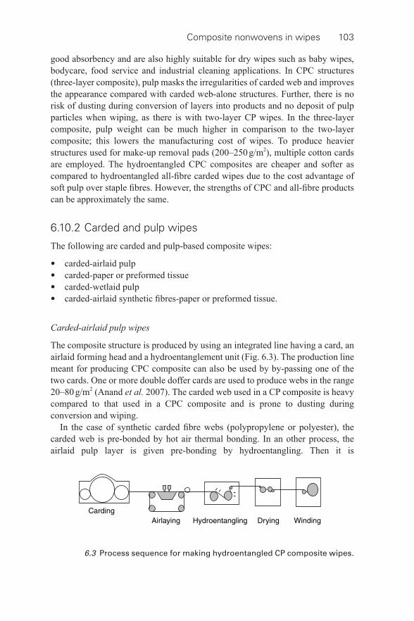
Composite nonwovens in wipes 103
good absorbency and are also highly suitable for dry wipes such as baby wipes, bodycare, food service and industrial cleaning applications. In CPC structures (three- layer composite), pulp masks the irregularities of carded web and improves the appearance compared with carded web- alone structures. Further, there is no risk of dusting during conversion of layers into products and no deposit of pulp particles when wiping, as there is with two- layer CP wipes. In the three- layer composite, pulp weight can be much higher in comparison to the two- layer composite; this lowers the manufacturing cost of wipes. To produce heavier structures used for make- up removal pads (200–250 g/m 2 ), multiple cotton cards are employed. The hydroentangled CPC composites are cheaper and softer as compared to hydroentangled all- fi bre carded wipes due to the cost advantage of soft pulp over staple fi bres. However, the strengths of CPC and all- fi bre products can be approximately the same.
6.10.2 Carded and pulp wipes
The following are carded and pulp- based composite wipes:
• carded- airlaid pulp • carded- paper or preformed tissue • carded- wetlaid pulp • carded- airlaid synthetic fi bres- paper or preformed tissue.
Carded- airlaid pulp wipes
The composite structure is produced by using an integrated line having a card, an airlaid forming head and a hydroentanglement unit ( Fig. 6.3 ). The production line meant for producing CPC composite can also be used by by- passing one of the two cards. One or more double doffer cards are used to produce webs in the range 20–80 g/m 2 (Anand et al. 2007). The carded web used in a CP composite is heavy compared to that used in a CPC composite and is prone to dusting during conversion and wiping.
In the case of synthetic carded fi bre webs (polypropylene or polyester), the carded web is pre- bonded by hot air thermal bonding. In an other process, the airlaid pulp layer is given pre- bonding by hydroentangling. Then it is
6.3 Process sequence for making hydroentangled CP composite wipes.
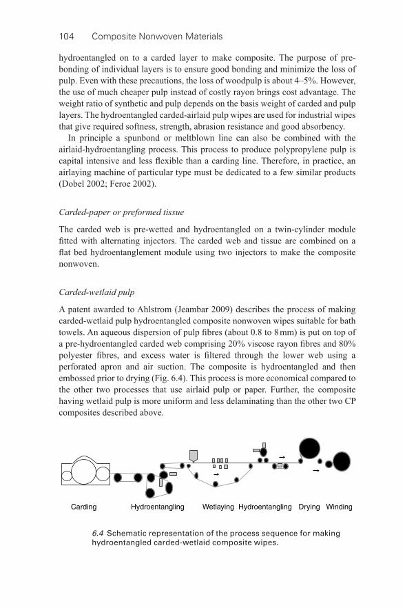
104 Composite Nonwoven Materials
hydroentangled on to a carded layer to make composite. The purpose of pre- bonding of individual layers is to ensure good bonding and minimize the loss of pulp. Even with these precautions, the loss of woodpulp is about 4–5%. However, the use of much cheaper pulp instead of costly rayon brings cost advantage. The weight ratio of synthetic and pulp depends on the basis weight of carded and pulp layers. The hydroentangled carded- airlaid pulp wipes are used for industrial wipes that give required softness, strength, abrasion resistance and good absorbency.
In principle a spunbond or meltblown line can also be combined with the airlaid- hydroentangling process. This process to produce polypropylene pulp is capital intensive and less fl exible than a carding line. Therefore, in practice, an airlaying machine of particular type must be dedicated to a few similar products (Dobel 2002; Feroe 2002).
Carded- paper or preformed tissue
The carded web is pre- wetted and hydroentangled on a twin- cylinder module fi tted with alternating injectors. The carded web and tissue are combined on a fl at bed hydroentanglement module using two injectors to make the composite nonwoven.
Carded- wetlaid pulp
A patent awarded to Ahlstrom (Jeambar 2009) describes the process of making carded- wetlaid pulp hydroentangled composite nonwoven wipes suitable for bath towels. An aqueous dispersion of pulp fi bres (about 0.8 to 8 mm) is put on top of a pre- hydroentangled carded web comprising 20% viscose rayon fi bres and 80% polyester fi bres, and excess water is fi ltered through the lower web using a perforated apron and air suction. The composite is hydroentangled and then embossed prior to drying ( Fig. 6.4 ). This process is more economical compared to the other two processes that use airlaid pulp or paper. Further, the composite having wetlaid pulp is more uniform and less delaminating than the other two CP composites described above.
6.4 Schematic representation of the process sequence for making hydroentangled carded- wetlaid composite wipes.
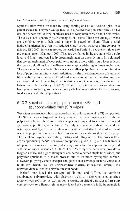
Composite nonwovens in wipes 105
Carded- airlaid synthetic fi bres- paper or preformed tissue
Synthetic fi bre webs are made by using carding and airlaid technologies. In a patent issued to Polymer Group Inc., it is reported that polyester fi bres of 1.2 denier fi neness and 38 mm length are used to form both carded and airlaid webs. These webs are separately hydroentangled on drums. These pre- entangled webs are combined over a belt and a paper is placed on them. Then a fi nal hydroentanglement is given with reduced energy to both surfaces of the composite (Moody III 2002). In one approach, the carded and airlaid webs are not given any pre- entanglement (Oathout 1995). They are combined in the dry state with a pulp layer and fi nally subjected to hydroentanglement on one side only. It is claimed that pre- entanglement of webs prior to combining them with a pulp layer reduces the loss of pulp fi bres into the fi ltrate water employed during hydroentanglement. The pre- entangled synthetic fi bre webs act to fi lter pulp fi bres, so as to minimize loss of pulp fi bre in fi ltrate water. Additionally, the pre- entanglement of synthetic fi bre webs permits the use of reduced energy input for hydroentangling the synthetic and pulp fi bre webs, which is also believed to contribute to reducing the loss of pulp fi bres (Moody III 2002). These composite nonwovens are stated to have good absorbency, softness and low particle counts suitable for clean rooms, food service and other applications.
6.10.3 Spunbond- airlaid pulp-spunbond (SPS) and spunbond- airlaid pulp (SP) wipes
Wet wipes are produced from spunbond- airlaid pulp-spunbond (SPS) composites. The SPS wipes are targeted for the price- sensitive baby wipe market. Both the pulp and polymer chips are much cheaper as compared to viscose rayon and synthetic staple fi bres, respectively. The pulp acts as an absorbent core and the outer spunbond layers provide abrasion resistance and structural reinforcement when the pulp is wet. In the core layer, cotton linters are also used in place of pulp. The spunbond layers resist linting, dusting and pilling in use. The process fl ow chart of producing the SPS nonwoven composite is given in Fig. 6.5 . The fi laments of spunbond layers can be crimped during production to improve porosity and softness of wipes (Anand et al. 2007). The SPS composite nonwoven provides a tougher surface and higher strength as compared to carded staple fi bre wipes, but polyester spunbond is a faster process due to its more hydrophilic surface. However, polypropylene is cheaper and gives better coverage than polyester due to its low density; so less polypropylene material is required. Overall, the polypropylene outscores polyester in spunbonds.
Reicofi l introduced the concepts of ‘in- line’ and ‘off- line’ to combine spunbonded polypropylene with absorbent webs to make wiping composites (Anonymous 2008, pp. 16–22). In both systems, an airlaid unit adds a fl uff- pulp core between two lightweight spunbonds and the composite is hydroentangled.
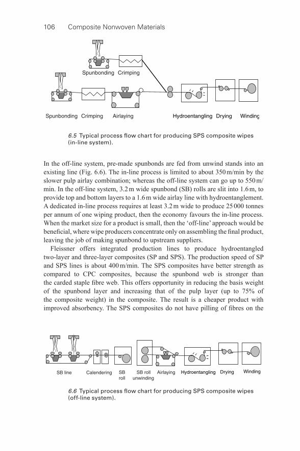
106 Composite Nonwoven Materials
In the off- line system, pre- made spunbonds are fed from unwind stands into an existing line ( Fig. 6.6 ). The in- line process is limited to about 350 m/min by the slower pulp airlay combination; whereas the off- line system can go up to 550 m/min. In the off- line system, 3.2 m wide spunbond (SB) rolls are slit into 1.6 m, to provide top and bottom layers to a 1.6 m wide airlay line with hydroentanglement. A dedicated in- line process requires at least 3.2 m wide to produce 25 000 tonnes per annum of one wiping product, then the economy favours the in- line process. When the market size for a product is small, then the ‘off- line’ approach would be benefi cial, where wipe producers concentrate only on assembling the fi nal product, leaving the job of making spunbond to upstream suppliers.
Fleissner offers integrated production lines to produce hydroentangled two- layer and three- layer composites (SP and SPS). The production speed of SP and SPS lines is about 400 m/min. The SPS composites have better strength as compared to CPC composites, because the spunbond web is stronger than the carded staple fi bre web. This offers opportunity in reducing the basis weight of the spunbond layer and increasing that of the pulp layer (up to 75% of the composite weight) in the composite. The result is a cheaper product with improved absorbency. The SPS composites do not have pilling of fi bres on the
6.5 Typical process fl ow chart for producing SPS composite wipes (in- line system).
6.6 Typical process fl ow chart for producing SPS composite wipes (off- line system).

Composite nonwovens in wipes 107
surface of the product unlike CPC and all staple fi bre carded products. Further, the SPS composites are more absorbent and cheaper because of the pulp, improved appearance and uniformity of the product due to spunbond layers, but have similar softness as compared to all- fi bre products.
Procter & Gamble has patented a process of making SPS composite nonwoven wet wipes with improved fl uid retention characteristics (Brennan and Balasubramanian 2007). When pre- moistened wipes are staked in an impervious container, some liquid from the top layers move to the bottom ones, resulting in gradients of liquid retention. The liquid retention (g/g) would be less and less from the bottommost wipes to the wipes stacked on the top layers. The bottom layers in a stack would be subjected to more pressure, leading to compaction of pores, so the liquid from the top layers would tend to move towards the wipes at the bottom. To objectively evaluate this, the ‘Saturation gradient index’ (SGI) is quantifi ed for the stacks of pre- moistened wipes. The SGI is the ratio of the average lotion load of the bottom ten wipes in a stack to that of the top ten wipes in that stack. An ideal ratio is one, which is diffi cult to get; nevertheless, a lower ratio is acceptable.
Various materials in the top and bottom spunbond layers were tried, such as polypropylene of 3 and 4 denier fi neness and 50/50 polypropylene/polyethylene (side by side in fi bre cross section) bicomponent fi bres of 2 and 3 deniers. The weight proportion of core pulp component in composite was about 30%. The composite structure was hydroentangled and patterned on the surfaces. All the wipes exhibited bi- modal distribution of pore sizes; the maximum peaks were observed at 240 μ m diameter pores for the 2 and 3 deniers bicomponent fi bres, whereas for the polypropylene fi bres of 3 and 4 deniers it was about 400 μ m diameter. The wipes containing the fi ner bicomponent polypropylene/polyethylene fi bres exhibited a lower SGI of about 1.3.
In another method of production of SP composite nonwovens, prior to hydroentanglement of the composite, the spunbond layer is pin/point thermal bonded between a roller with square pins and a plain anvil roller, such that about 16% of the surface area of the layer has a bonded surface. If the spunbond layer is loosely bonded, the fi laments are generally too mobile to form a coherent matrix to secure the pulp fi bres during hydroentangling. On the other hand, if the total bonded area of the substrate is too great, the penetration of pulp fi bres into the substrate will be poor and also cause a splotchy composite fabric because the jets of water will splash and wash off pulp fi bres (Everhart et al. 1994).
6.10.4 Carded-SMS (CSMS) and carded-SMS-carded (CSMSC) wipes
Conventional sanitary wipes such as baby wipes, hand wipes, household cleaning wipes and industrial wipes are made from a single layer of homogeneous material
108 Composite Nonwoven Materials
or a mixture of synthetic and cellulose fi bres. In single- layer wipes, it is diffi cult to optimize the physical characteristics of a wipe, such as thickness, texture, strength, structural integrity, softness, fl exibility, opacity and resiliency depending on the application. A patent (Child et al., 2010) describes production of two- and three- layer nonwoven wipes for sanitary application. In two- layer structures, the top layer is carded and consists of viscose and polyester (30:70), the bottom layer is SMS. In a three- layer structure, the SMS layer is sandwiched between the two outer carded web layers. The SMS may be pre- bonded. When pre- bonding is not required, multiple beams of SB and MB can be installed directly into the wipe production line instead of a roll unwind to introduce a previously formed fabric. The total composition (all the layers) is hydroentangled. In addition, they can be hydropatterned by using a square design.
It is also possible to produce webs using airlaid or wetlaid from staple fi bres consisting of a mixture of synthetic (polypropylene or polyester fi bres) and cellulosic (viscose rayon, cotton, pulp, bamboo, hemp or blends) or PLA fi bres (polylactide). The layers can be bonded by using thermal or chemical or hydroentangling.
Compared to single- layer wipes, the multilayer wipes exhibited improved opacity and tensile strength and reduced elongation in cross direction for a given basis weight. Meltblown structures have superior opacity due to better coverage of fi bres in fabric. A composite wipe relatively light in weight offers the visual security of high opacity and provides lower ratios of tensile strength (MD/CD) and elongation (CD/MD). The tensile strength in cross direction is relatively closer in value to that in machine direction compared to other wipes. The composite wipes provided more uniform multi- directional strength. The orientation of fi bres in all layers of SMS and draft on the card webs must be controlled to get the desired effect.
6.10.5 Carded- spunbond (CS) wipes
The carded- spunbond composite nonwoven combines the benefi ts of carded (bulkiness, drape, softness and resilience) and spunbond (strength) to wiping products. The splitting of bicomponent fi bres during the spunbonding and meltblowing processes is possible. Differentially shrinking bicomponent fi laments having eccentric core- sheath or an asymmetric arrangement of components can be split into helically crimped fi laments by quenching after extrusion and deposited on to carded web or sandwiched between two carded webs to produce soft and bulky fabrics. The size of fi bre after splitting is about 200 nm to 1000 nm, whereas regular fi bres obtained during the meltblowing process is in the range of 500 nm to 10000 nm. This shows the benefi t of using bicomponent fi bres in generating a very large surface area to obtain a textile like softness to wipes. Hydroentangling can be performed at low pressure as fi bres are already very fi ne so require less energy.
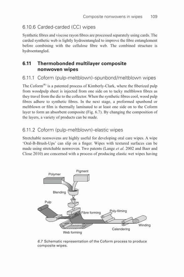
Composite nonwovens in wipes 109
6.10.6 Carded- carded (CC) wipes
Synthetic fi bres and viscose rayon fi bres are processed separately using cards. The carded synthetic web is lightly hydroentangled to improve the fi bre entanglement before combining with the cellulose fi bre web. The combined structure is hydroentangled.
6.11 Thermobonded multilayer composite
nonwoven wipes
6.11.1 Coform (pulp- meltblown)-spunbond/meltblown wipes
The Coform (R) is a patented process of Kimberly-Clark, where the fi berized pulp from woodpulp sheet is injected from one side on to tacky meltblown fi bres as they travel from the die to the collector. When the synthetic fi bres cool, wood pulp fi bres adhere to synthetic fi bres. In the next stage, a preformed spunbond or meltblown or fi lm is thermally laminated to at least one side on to the Coform layer to form an absorbent composite ( Fig. 6.7 ). By changing the composition of the layers, a variety of products can be made.
6.11.2 Coform (pulp- meltblown)-elastic wipes
Stretchable nonwovens are highly useful for developing oral care wipes. A wipe ‘Oral-B-Brush-Ups’ can slip on a fi nger. Wipes with textured surfaces can be made using stretchable nonwoven. Two patents (Lange et al. 2002 and Baer and Close 2010) are concerned with a process of producing elastic wet wipes having
6.7 Schematic representation of the Coform process to produce composite wipes.
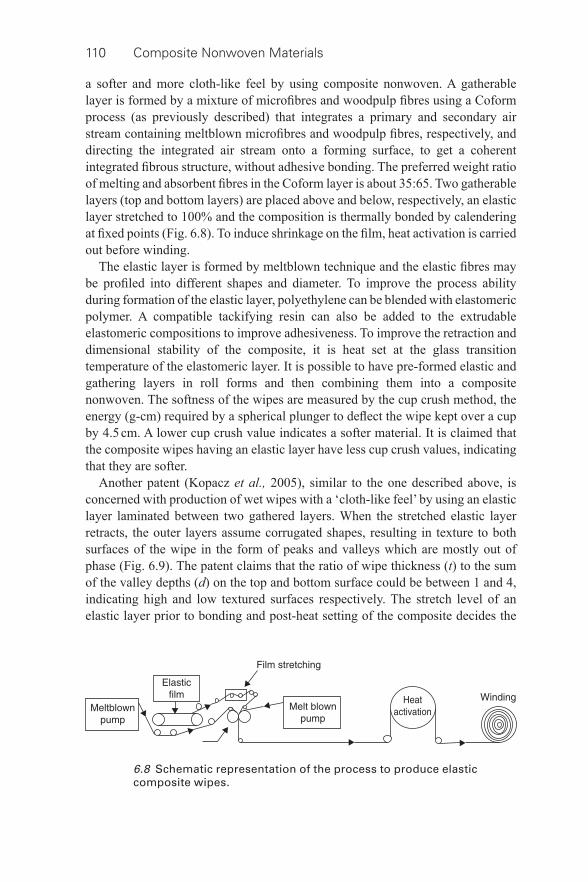
110 Composite Nonwoven Materials
a softer and more cloth- like feel by using composite nonwoven. A gatherable layer is formed by a mixture of microfi bres and woodpulp fi bres using a Coform process (as previously described) that integrates a primary and secondary air stream containing meltblown microfi bres and woodpulp fi bres, respectively, and directing the integrated air stream onto a forming surface, to get a coherent integrated fi brous structure, without adhesive bonding. The preferred weight ratio of melting and absorbent fi bres in the Coform layer is about 35:65. Two gatherable layers (top and bottom layers) are placed above and below, respectively, an elastic layer stretched to 100% and the composition is thermally bonded by calendering at fi xed points ( Fig. 6.8 ). To induce shrinkage on the fi lm, heat activation is carried out before winding.
The elastic layer is formed by meltblown technique and the elastic fi bres may be profi led into different shapes and diameter. To improve the process ability during formation of the elastic layer, polyethylene can be blended with elastomeric polymer. A compatible tackifying resin can also be added to the extrudable elastomeric compositions to improve adhesiveness. To improve the retraction and dimensional stability of the composite, it is heat set at the glass transition temperature of the elastomeric layer. It is possible to have pre- formed elastic and gathering layers in roll forms and then combining them into a composite nonwoven. The softness of the wipes are measured by the cup crush method, the energy (g- cm) required by a spherical plunger to defl ect the wipe kept over a cup by 4.5 cm. A lower cup crush value indicates a softer material. It is claimed that the composite wipes having an elastic layer have less cup crush values, indicating that they are softer.
Another patent (Kopacz et al., 2005), similar to the one described above, is concerned with production of wet wipes with a ‘cloth- like feel’ by using an elastic layer laminated between two gathered layers. When the stretched elastic layer retracts, the outer layers assume corrugated shapes, resulting in texture to both surfaces of the wipe in the form of peaks and valleys which are mostly out of phase ( Fig. 6.9 ). The patent claims that the ratio of wipe thickness ( t ) to the sum of the valley depths ( d ) on the top and bottom surface could be between 1 and 4, indicating high and low textured surfaces respectively. The stretch level of an elastic layer prior to bonding and post- heat setting of the composite decides the
6.8 Schematic representation of the process to produce elastic composite wipes.
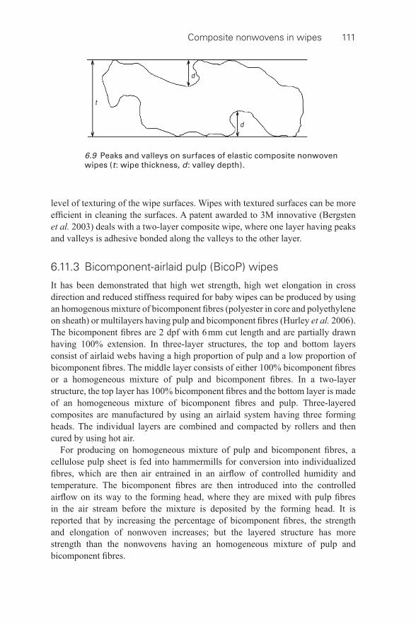
Composite nonwovens in wipes 111
level of texturing of the wipe surfaces. Wipes with textured surfaces can be more effi cient in cleaning the surfaces. A patent awarded to 3M innovative (Bergsten et al. 2003) deals with a two- layer composite wipe, where one layer having peaks and valleys is adhesive bonded along the valleys to the other layer.
6.11.3 Bicomponent- airlaid pulp (BicoP) wipes
It has been demonstrated that high wet strength, high wet elongation in cross direction and reduced stiffness required for baby wipes can be produced by using an homogenous mixture of bicomponent fi bres (polyester in core and polyethylene on sheath) or multilayers having pulp and bicomponent fi bres (Hurley et al. 2006). The bicomponent fi bres are 2 dpf with 6 mm cut length and are partially drawn having 100% extension. In three- layer structures, the top and bottom layers consist of airlaid webs having a high proportion of pulp and a low proportion of bicomponent fi bres. The middle layer consists of either 100% bicomponent fi bres or a homogeneous mixture of pulp and bicomponent fi bres. In a two- layer structure, the top layer has 100% bicomponent fi bres and the bottom layer is made of an homogeneous mixture of bicomponent fi bres and pulp. Three- layered composites are manufactured by using an airlaid system having three forming heads. The individual layers are combined and compacted by rollers and then cured by using hot air.
For producing on homogeneous mixture of pulp and bicomponent fi bres, a cellulose pulp sheet is fed into hammermills for conversion into individualized fi bres, which are then air entrained in an airfl ow of controlled humidity and temperature. The bicomponent fi bres are then introduced into the controlled airfl ow on its way to the forming head, where they are mixed with pulp fi bres in the air stream before the mixture is deposited by the forming head. It is reported that by increasing the percentage of bicomponent fi bres, the strength and elongation of nonwoven increases; but the layered structure has more strength than the nonwovens having an homogeneous mixture of pulp and bicomponent fi bres.
6.9 Peaks and valleys on surfaces of elastic composite nonwoven wipes ( t : wipe thickness, d : valley depth).
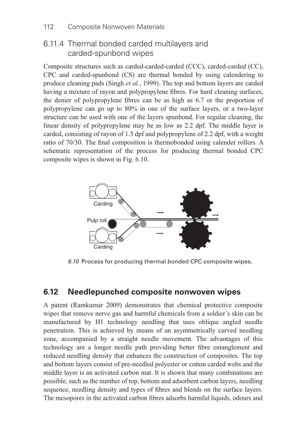
112 Composite Nonwoven Materials
6.10 Process for producing thermal bonded CPC composite wipes.
6.11.4 Thermal bonded carded multilayers and carded- spunbond wipes
Composite structures such as carded- carded- carded (CCC), carded-carded (CC), CPC and carded- spunbond (CS) are thermal bonded by using calendering to produce cleaning pads (Singh et al. , 1999). The top and bottom layers are carded having a mixture of rayon and polypropylene fi bres. For hard cleaning surfaces, the denier of polypropylene fi bres can be as high as 6.7 or the proportion of polypropylene can go up to 80% in one of the surface layers, or a two- layer structure can be used with one of the layers spunbond. For regular cleaning, the linear density of polypropylene may be as low as 2.2 dpf. The middle layer is carded, consisting of rayon of 1.5 dpf and polypropylene of 2.2 dpf, with a weight ratio of 70/30. The fi nal composition is thermobonded using calender rollers. A schematic representation of the process for producing thermal bonded CPC composite wipes is shown in Fig. 6.10 .
6.12 Needlepunched composite nonwoven wipes
A patent (Ramkumar 2009) demonstrates that chemical protective composite wipes that remove nerve gas and harmful chemicals from a soldier’s skin can be manufactured by H1 technology needling that uses oblique angled needle penetration. This is achieved by means of an asymmetrically curved needling zone, accompanied by a straight needle movement. The advantages of this technology are a longer needle path providing better fi bre entanglement and reduced needling density that enhances the construction of composites. The top and bottom layers consist of pre- needled polyester or cotton carded webs and the middle layer is an activated carbon mat. It is shown that many combinations are possible, such as the number of top, bottom and adsorbent carbon layers, needling sequence, needling density and types of fi bres and blends on the surface layers. The mesopores in the activated carbon fi bres adsorbs harmful liquids, odours and
Composite nonwovens in wipes 113
chemicals during wiping of contaminated surfaces such as human skin and cloth, etc., while the surface layer helps in trapping the particles and providing a soft feel. The wipe had a PMP (Soman) uptake of about 0.15 g/g as compared to the 0.06g/g uptake of the M291 decontamination kit currently issued to troops in the US military (Anonymous 2008).
6.13 Other multilayer nonwoven wipes
Wipes for abrasive market contain meltblown material combined with either a needlepunched or spunlaced layer, to offer high bulk and abrasiveness. Jacob Holm’s Bi- active is one such product. SMS and SM polypropylene oil sorbent pads have increased strength, durability and reusability than single- layer meltblown pads. However, the oil sorption and retention capacities must be low as compared to meltblown pads as the spunbond layers have larger pores due to the presence of coarse fi bres in the structure.
6.14 Conclusion and future trends
The developments that have taken place in composite nonwovens will be pursued more vigorously by wipe manufacturers by using permutations and combinations of different fi bres, pulps, blends, webs, layering, additives and technologies to stay ahead of each other. This will result in many wipe products being marketed, ranging from value added to affordable wipes in the consumer and industrial sectors. In future, the price competition will intensify in household cleaning wipes, so the nonwovens need to be economical. Many wipes in personal care and for household use will be introduced in the market with added functionalities, so much so that the consumer will be confused by the choice. Wipe manufacturers must be cautious in developing new products and should lay greater emphasis in differentiating their products. When nonwoven manufacturers develop new wipe substrates, advanced nonwovens will be available to enhance wipe differentiation and stimulate demand in the creative product category. The independent wipe manufacturers must acquire broad capabilities for formulation of compositions, selection of substrates, product put- up options, rapid production turnaround, packaging, cost control, quality assurance and timely delivery of products.
Nevertheless, the environmental pressure will oblige the wipe manufacturers to focus simultaneously on the aspects of developing wipes using recycled fi bres and biodegradable fi bres that are fl ushable- dispersible-biodegradable. The demand for truly dispersible nonwovens for fl ushable wipes will increase. It has been demonstrated that bicomponent fi bres that are splittable during hydroentanglement offer a very fi ne and smooth fi bre surface, but their cost is prohibitive for use on a large scale in technical wipes and high end personal care wipes. When these fi bres are affordable, many value added wipe products will be available in future.
114 Composite Nonwoven Materials
6.14.1 Wipes from recycled fi bres
Reduce, Reuse, Recycle; these words have become synonymous with the Green Movement (Anonymous 2011b). Wipe manufacturers are working hard to make sure that their customers have lots of choice when it comes to environmentally friendly products. Some of Ahlstrom’s spunlace products are made from recycled polyester. The recent trend is to produce wipes from recycled fi bres, so that the impact of landfi ll arising out of disposable wipes can be minimized. In future, the trend of producing recycled polyester fi bres from used bottles and containers, and producing wipes from these fi bres, will pick up. It has been shown that fi ve 16-oz polyester bottles will produce 72 wipes each of 50 g made with 70% recycled polyester (EcoSure fi bres) and 30% others. The recycling of polyester reduces energy consumption by 84% and greenhouse emissions by 71% (Katz 2011).
Recycled rayon fi bres from used woven or knitted fabrics are also used for making industrial wipes to a limited extent. The nonwovens from recycled fi bres are made in dry form and are latex bonded to provide low linting. Wipes made from cotton recycled from jeans, shirts, towels, sheets and other clothing will also increase. The problem with recycled cotton is the high variability in length which poses a little challenge in carding (Anonymous 2011b).
6.14.2 Wipes from biodegradable materials
Every year, about 250 000 tonnes of wipes are disposed in landfi lls after use. One can imagine the environmental impact they pose to present and future generations, even if they contain a low proportion of synthetic fi bres. Environmental concerns are raised from many quarters and the talk of reducing carbon footprints in many forums is gaining momentum. Pressure from the environmental lobby and citizens from Europe and America will force many governments to pass regulations on production, use and disposable aspects of wipes that are made from non- biodegradable fi bres such as polyester and polypropylene.
In anticipation of this, the leading wipe manufacturers are focusing their research on developing biodegradable wipes and wipes having a smaller proportion of synthetic fi bres. But the availability of a large quantity of natural (cotton) and industrial- made biodegradable materials (viscose rayon, Tencel) and the cost associated with them are the issues to be addressed. The effort made in this direction yielded wipes that are prepared with more woodpulp content and a smaller content of viscose and non- biodegradable petroleum fi bres. However, the economy favours petroleum fi bres, as they are cheaper, stronger and at present abundantly available.
Suominen’s ‘Biolace’ and Sandler’s ‘Bio wipes’ are composed of 100% viscose fi bres, which are fully biodegradable and are certifi ed according to the PEFC (Programme for the Endorsement of Forest Certifi cation) standard
Composite nonwovens in wipes 115
which advocates sustainable handling of wood and products made from it (McIntyre 2011). A recent innovation to produce cellulosic nonwovens by using meltblown technology is very encouraging. Meltblown lyocell nonwovens which have potential applications in wipes are produced in a pilot scale plant by the Fraunhofer Institute by combining its Lyocell process with Weyerhaeuser’s meltblown and Reicofi l’s nozzle. The dope extruded through a die is subjected to hot blown air and subsequently coagulated by spraying water or a mixture of water with NMMO. This results in a self- bonded nonwoven without distinct adhesion of single fi bres. Practical tests have shown that fi lms are formed when the dope is not sprayed with water. The production of durable wipes requires a maximum tensile strength of 1600 N/m for basis weight less than 100 g/m 2 . This could be achieved by a meltblown- lyocell microfi bre self- bonded nonwoven with a basis weight of 65 g/m 2 . The liquid absorptive capacity and wicking rate of this cellulose- meltblown nonwoven are similar to the spunlaced nonwovens made from viscose rayon or lyocell fi bres (Ebeling et al., 2006). Depending on the throughput, webs of 8–50 g/m 2 having fi bres about 4 to 8 micron diameter are produced. These webs are strong, lint free and resembling traditional spunbond rather than meltblown products (Anonymous 2008).
There will be renewed interest on cotton wipes in the future. The use of cotton in nonwovens is less than 2% of all fi bres currently used. In the USA, commercial products like cosmetic pads and facial wipes contain 100% cotton. Differentially entangled carded cotton nonwoven using hydroentangling is reported (Barge et al., 2004). A similar concept is used in Japan to produce hydroentangled cotton cosmetic pads (wet wipes). The drylaid fi bres are hydroentangled by using extremely low injector pressure (40 bar). This results in very low entanglement of core fi bres, whereas the surface fi bres have an adequate degree of entanglement. This maximizes the porosity for better absorbency and minimizes the linting in use (Anand et al., 2007). The other approaches followed to bond the fi bres in web are: surface impregnation with binder; thermal bonding with bicomponent fi bres; and embossing by using calender rollers.
Most of the cotton used in the nonwovens up until now has been bleached, which is expensive and complex to process, especially in carding. This affects the production rate of a hydroentanglement line. So there is considerable effort to develop a wipe using nonbleached (virgin) cotton. SRRC, New Orleans has demonstrated that virgin cotton could be processed directly on existing carding equipment. Several lightly pre- needled webs of virgin cotton were produced on commercial needlepunching equipment to investigate further bonding using hydroentanglement. During this hydroentanglement, a large proportion of wax is removed at low energy, which increases the hydrophilicity of fi bres, an essential requirement for wet wipes. This is advantageous as the costly process of scouring and bleaching of cotton and the diffi culty in processing it might be eliminated (Anonymous 2011c). The strength of hydroentangled cotton fabrics tends to increase as the fi bre becomes fi ner but the fabrics have a harsher handle. Fine
116 Composite Nonwoven Materials
cotton fi bres are prone to form neps in hydroentangling, hence coarser cotton fi bres are preferred; an added advantage as coarser cotton fi bres are cheaper than the fi ner ones.
The solvent spun cellulosic fi bre, Tencel (formerly lyocell) from Lenzing have higher wet strength and wet modulus than viscose rayon. Their absorbency is slightly lower than viscose rayon but still good for wiping products. These properties provide resistance for wet wipes to prevent them collapsing during use. Lyocell fi bres are dispersed easily in water. Because of their relatively high modulus than viscose rayon fi bres, longer lengths can be used for wet laying. Their round cross section produce large amounts of inter- fi bre contact resulting in a high degree of cohesion of the wet web. This facilitates excellent web transfer. Their low water imbibition allows easier drying of the web during processing (White 2007). Further, their ability to fi brillate under applied force such as used in hydroentangling make them fi ner with a large surface area. This offers a smooth fi bre surface to the wipes, making them very soft, but still strong (Anonymous 2011b) and also with excellent pattern defi nition. Because of the superior properties of Tencel fi bres, they will be used as wetlaid- hydroentangled nonwoven wipes, especially in the wet wipes category in future.
More recently, a nonwoven manufacturer has partnered with a fi bre developer to create technology that allows for the incorporation of PLA (polylactide) fi bres into a hydroentangled web that will naturally biodegrade in landfi lls in two weeks (Robinson 2005). At Fiberweb, efforts are focused to develop PLA fi bre nonwovens that can be thermal embossed with attractive patterns suitable for baby wipes. Currently, PLA fi bres are expensive and supply is limited.
6.14.3 Dispersible nonwovens for fl ushable wipes
The wipes which are ideal candidates for fl ushability are ones that can be disposed of immediately, rather than stored in the home waste receptacles. Customers prefer baby wipes, bathroom cleaning wipes, feminine hygiene wipes, haem-orrhoidal wipes and medicinal pads to be fl ushable. A truly dispersible wipe is one which can disperse like toilet paper in a short time after being put in the toilet and fl ushed out and should not clog up the plumping system to the city sewage treatment plant causing breakdown or increased maintenance of the entire sewage system. It is important that fl ushable products are not buoyant and readily sink to the bottom of the holding tank so that they can be removed with the sludge (Drinkwater et al., 2011). The wipes produced from short cellulose fi bres using wetlaid- hydroentangling do not have adequate strength in use as wet wipes but are dispersible and biodegradable.
Currently, for making fl ushable wipes, airlaid pulp is bonded by ion sensitive cationic polymer binders or by light hydroentanglement. Trigger technologies use a component that causes the nonwoven web to change its strength properties after it is immersed in water by becoming weak enough to be
Composite nonwovens in wipes 117
fl ushable. Kimberly-Clark introduced such triggerable binders. The ion level based triggers are better compatible with sanitation applications and skin contact (Mango 2004, 2008). Three- layer composites with wetlaid pulp in the core supported by fi bre webs comprising synthetic and natural fi bres are hydroentangled at selected areas, leaving others unbonded to promote disintegration of the structure in the sewer system (Ngai 2003). Hydraspun (R) 784 is one such wipe. The wet strength of this product prior to fl ushing is suffi cient for current wipe applications, but may limit the development of other markets in the future. It is reported that it prevents strain on municipalities’ sewage treatment systems and it passes ISO 14851 biodegradability tests (Levy 2011).
Wetlaid fabric composed of short synthetic and natural fi bres can be produced for dispersible wipes. All these wipes are designed to breakdown under agitation in water. Water dispersible fi bres from sulfopolyester and multicomponent fi bres comprising water dispersible sulfopolyester and non- dispersible polymer arranged side by side in the cross section of fi bre are reported (Haile et al., 2012). These have potential applications in fl ushable wipes.
Mechanically weakened two- layered structures joined together by water responsive binders are targeted as dispersible- fl ushable wet wipes (Noda et al., 2010). The layers could be carded or airlaid webs consisting of cellulose fi bres or blends with pulp. Each layer is passed between a pair of gear/tooth- shaped cylinders or the pair could be a combination of a recessed top cylinder and a smooth bottom cylinder. This weakens the layers at selective locations. The layers are staggered during overlapping such that a weakened portion on the top layer does not coincide with that of the bottom layer, so that the wipes have adequate strength in use. The fi bres and the structures are said to be stable up to three years in pre- moistened wipes. During fl ushing, the agitation of water is suffi cient to disperse the fi bres in the toilet. This type of wipe made from biodegradable fi bres with the right selection of fi bre length, controlled weakening and binding of layers could be a potential candidate as a truly dispersible- fl ushable wipe.
Many wipes currently marketed as ‘fl ushable’ contain a small proportion of non- biodegradable fi bres to give adequate strength to the wipes in use. These are only fl ushable and not dispersible in the true sense that they do not degrade, hence they clog the plumping and sewer systems in the form of fi bre clumps. In future, many city governments will pass stringent regulations on disposable aspects of fl ushable wipes. A truly dispersible wipe could be made only by using biodegradable materials (pulp, short natural or regenerated fi bres) and appropriate web forming and bonding technique (including binders or controlled entanglement of fi bres). Further, they should have adequate wet strength and cleaning ability. Development of raw material must be compatible with a variety of water treatment technologies utilized. The chemicals used in waste water systems do not allow to re- gather the dispersed fi bres from the fl ushed- out wipes. In terms of raw materials, most experts focus on traditional biodegradable fi bres with some form of cellulose- like pulp, short rayon or short cotton fi bres (Kim and Hergeth 2012).
118 Composite Nonwoven Materials
The airlaid, carded and wetlaid technologies are promising for making truly dispersible wipes. The insolubilized polymeric binders developed for premoistened tissue, that can cause a wet wipe with effective wet strength in a lotion to lose strength in water on dilution (ion concentration trigger), have real potential in fl ushable wipe applications (Mango 2004). The patent protected status of these binders and the required skills in processing are the deterrent for developing fl ushable wipes. Developing true dispersible nonwovens for fl ushable wipes that are functional and affordable will undoubtedly pose tremendous challenges to wipe manufacturers in future.
6.15 References
Anand , SC , Brunnschweiler , D , Swarbrick , G and Russell , SJ ( 2007 ) ‘ Mechanical bonding ’ in Handbook of nonwovens , Edited by S. J. Russell , Woodhead Publishing , Cambridge .
Anonymous ( 2008 ) ‘ Issue of convenience: Eco- friendly, multi- purpose products are driving demand in the wipes market ’, Nonwovens Report International , 1 : 16 – 22 .
Anonymous ( 2011 a) ‘ Wipes Market Watch ’, Household & Personal Care Wipes/Fall pp. 10 – 16 .
Anonymous ( 2011 b) ‘ Nice-Pak: World’s largest wet wipes producer ’, Household & Personal Care Wipes , Fall, pp. 22 – 29 .
Anonymous ( 2011 c) ‘ Cotton’s potential for padding nonwovens ’, Agricultural Research , September , pp. 14 – 17 .
Baer , DJ and Close , KB ( 2010 ) US Patent 7,681,756 B2, March 2010 . Barge , P , Carter , N and Fuller , C ( 2004 ) US Patent 0,068,849 A1, April 2004 . Bell , I ( 2011 ) ‘ Wipes: Still a relevant format in the post- recession era ’, www.nonwovens-
industry.com , pp. 38 – 40 . Bergsten , RE , Ericson , JL , Haskett , TE , Pollock , MH and Sudo , Y ( 2003 ) US Patent
0,171,051 A1, September 2003 . Bitz , K ( 2002 ) ‘ Air laid: what is next? ’ www.nonwovens- industry.com , October , pp. 30 . Black , SK and Deleon , S ( 2004 ) European Patent 1,434,904. Brennan , JP and Balasubramanian, A ( 2007 ) US Patent 0,228,064 A1, October 2007 . Chang , KS and Edward ( 2004 ) SD European Patent 1,454,000. Child , W , Damaghi R and Duane , LE ( 2010 ) US Patent 0,062,671 A1, March 2010 . Dobel , J ( 2002 ) ‘ The future of airlaid forming ’, Nonwovens World , June - July , pp. 53 . Drinkwater , A , Galletti , S and Poinel , L ( 2011 ) ‘ Out of sight, but not of mind ’, Nonwovens
Report International , 1 : 64 – 65 . Ebeling , E , Fink , HP , Luo , M and Geus , HH ( 2006 ) ‘ Cellulose meltblown nonwovens
using the Lyocell- process ’, Lenzinger Berichte , 86 : 124 – 131 . Edana , http://www.edana.org/uk/nonwovens/wipes.html . Ellis , D , West , J , Mayhorn , J and Carter , N ( 2011 ) US Patent 7,915,184, March 2011 . Evans , FJ and Shambelan , C ( 1970 ) US Patent 3,498,874. Everhart , CH , Fischer , DO , Radwanski , FR and Skoog , H ( 1994 ) US Patent 5,284,703,
February 1994 . Feroe , D ( 2002 ) ‘ Two layer air- lace technology ’, Paper presented in Marketing Technology
Service, MTS, Conference , Ottawa, Canada . Frederick , RC ( 2004 ) ‘ Oral-B Brush-Ups wipe breath clean ’, www.nonwovens- industry.
com September , pp. 24 .
Composite nonwovens in wipes 119
Haile , WA , George , SE , Hale , RW and Jenkins WL ( 2012 ) US Patent 8,247,335, Aug 2012 . Hurley , JS , Boehmer , B , Campbell , AJ , Moore , JM , Vercauteren , DW . Burgess BG and
Horton ( 2006 ) HF US Patent 0,154,547 A1, July 2006 . Jeambar , P ( 2009 ) US Patent 7,484,276 B2, Feb. 2009 . Johnson , M and Lindquist , TJ ( 2010 ) US Patent: 7,829,478 B2, November , 2010 . Katz , S ( 2011 ) ‘ Wipes from recycled fi bres ’, Household & Personal Care Wipes , Fall,
pp. 24 – 29 . Keck , LE , Varona , EG and Wright , AE ( 2006 ) US Patent 0,068,167 A1, March 2006 . Kim , MJ and Hergeth , HH ( 2012 ) ‘ Technology roadmap for fl ushable nonwoven wipes ’,
J Textile Inst. , 103 : 200 – 209 . Kopacz , TJ , Zander , TM , Pawar , PL , Kremer T and Wright ( 2005 ) AE US Patent 0148,260
A1, July 2005 . Lange , SR , Close , KB , Baer , DJ , Smith CA and Beck , RC ( 2002 ) US patent 0,127,937 A1,
September 2002 . Levy , ( 2011 ) ‘ The Game Changer: Sustainability ’, www.nonwovens- industry.com ,
February , pp. 32 – 39 . Mango , P ( 2004 ) ‘ Flushable wipes – past, present, and future ’, www.nonwovens- industry.
com , December , pp. 64 – 71 . Mango , P ( 2008 ) ‘ Flush with success, new dispersible toilet care wipes lead the charge ’,
Paper presented at the International Conference ‘Insight 2008’ Section 5, St. Louis, MO, October.
McIntyre , K ( 2009 ) ‘ The Industrial Wipes Market ’, www.nonwovens- industry.com , October .
McIntyre , K ( 2011 ) ‘ Spunlace Showdown ’, www.nonwovens- industry.com , March , pp. 70 – 76 .
Merriam-Webster Dictionary , http://merriam- webster.com/ Moody III , RA ( 2002 ) US Patent 6,381,817 B1, May 2002 . Ngai , MC ( 2003 ) European Patent 1,354,093. Noda , I , Gross , S and Donnell , HO ( 2010 ) US Patent 7,838,725 B2, November 2010 . Oathout , JM ( 1994 ) US Patent: 5,320,900, June , 1994 . Oathout , JM ( 1995 ) US Patent 5,459,912, October , 1995 . Ramkumar , SS ( 2009 ) US Patent 7,516,525 B2, April 2009 . Rivera , CM , Terrier , A and Gomez , EC ( 2009 ) US Patent 0,260,173 A1, October 2009 . Robinson , J ( 2005 ) ‘ Wet wipes – Convenience in Technology – Product Development for
Growth ’, Nonwoven Industry , October , pp. 110 – 114 . Sahu , PB ( 2012 ) ‘ Wipes: What, Where, Why & How? ’ www.nonwovens- industry.com/
issues/ , January , 2012 . Singh , B , Colace , A , Lee , L and Sternberg , E ( 1999 ) WO (World Intellectual Property
Organization) Patent 46119, September 1999 . Watzl , A ( 2006 ) ‘ Chances for cost savings in production of hygiene, medical and
wipe: Spunlace/airlaid combinations offer great opportunities ’, www.nonwovens- industry.com , May 2006 , pp. 20 – 23 .
White , C ( 2007 ) ‘ Wet- laid web formation ’, in Handbook of Nonwovens , edited by S. J. Russel , Woodhead Publishing , Cambridge .
Wilson , A ( 2004 ) ‘ Going west and escaping the loop ’, Nonwovens Report International , September , pp. 12 – 18 .
Wilson , W ( 2003 ) ‘ Convenience conquers ’, Nonwovens Report International . September , pp. 12 – 18 .
120
© 2014 Woodhead Publishing Limited
7 Composite nonwovens in fi lters: theory
A. MUKHOPADHYAY, National Institute of Technology Jalandhar, India
DOI: 10.1533/9780857097750.120
Abstract: This chapter embodies fi ltration mechanisms and characteristic requirements of nonwovens as fi lters. Different fi ltration media rely on different physical interaction mechanisms for separation and collection of particles. Apart from the most common particle entrapment by physical principles while separating solids from liquid/gases, different mechanisms exist in liquids–liquids separations and gas–liquid separations. Textile fi lter media have proved to be superior in many applications of gas and liquid fi ltration. Among textile media, use of nonwovens is most prominent as the fi lter media. Structure and media characteristics largely depend on fi ltration-specifi c requirements, machine oriented requirements and application oriented requirements.
Key words: adsorption/absorption, coalescing, mechanisms of fi ltration, media characteristics, particle capture/entrapment.
7.1 Introduction
A fi lter medium is any material that, under the operating conditions of the fi lter, is permeable to one or more components of a mixture, solution, or suspension, and is impermeable to the remaining components. Broadly, the fi ltration process embodies solids–gases separations, solids–liquids separations, solids–solids separations, liquids–liquids separations, gas–liquid separations, and gas–gas separations and these are an essential part of countless industrial processes, contributing to the following:
• purity of product; • imbibing functional performance (e.g., cleanroom for tissue culture); • saving in energy; • improvement in product and process effi ciency; • protection of machine/instruments and their components; • recovery of precious materials; • environmental pollution control.
The fl uid stream to be fi ltered may be liquid or gas. Figure 7.1 shows the major uses of fi lters. Wide variations in fi lter material composition and structures are available in the market, depending on the fi eld of application. Although the random fi bre structure is the backbone of the web, it may contain other components that are part of the forming process, including (but not limited to) particulate
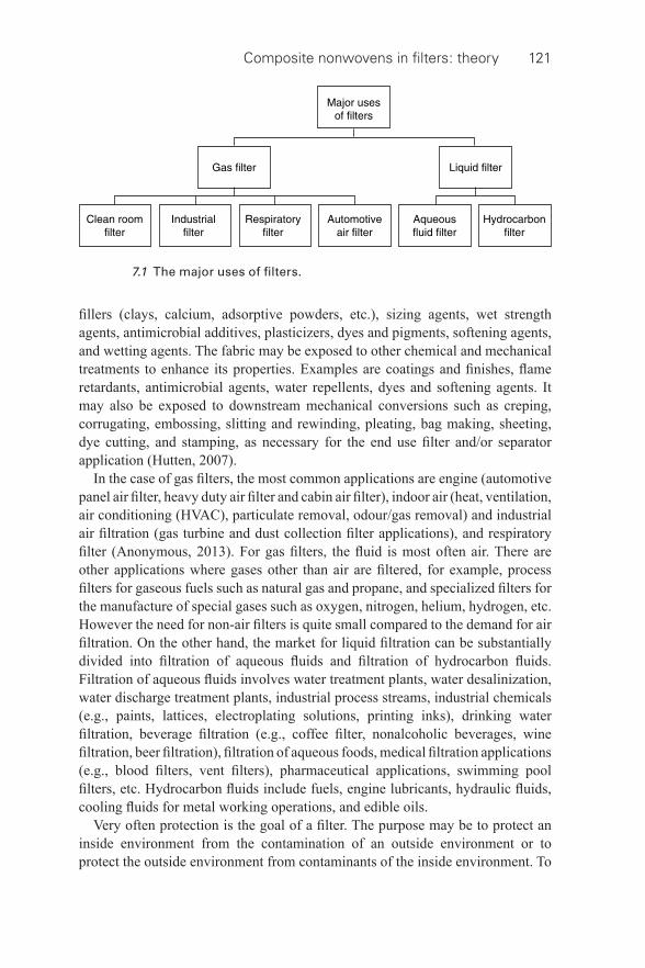
Composite nonwovens in fi lters: theory 121
fi llers (clays, calcium, adsorptive powders, etc.), sizing agents, wet strength agents, antimicrobial additives, plasticizers, dyes and pigments, softening agents, and wetting agents. The fabric may be exposed to other chemical and mechanical treatments to enhance its properties. Examples are coatings and fi nishes, fl ame retardants, antimicrobial agents, water repellents, dyes and softening agents. It may also be exposed to downstream mechanical conversions such as creping, corrugating, embossing, slitting and rewinding, pleating, bag making, sheeting, dye cutting, and stamping, as necessary for the end use fi lter and/or separator application (Hutten, 2007).
In the case of gas fi lters, the most common applications are engine (automotive panel air fi lter, heavy duty air fi lter and cabin air fi lter), indoor air (heat, ventilation, air conditioning (HVAC), particulate removal, odour/gas removal) and industrial air fi ltration (gas turbine and dust collection fi lter applications), and respiratory fi lter (Anonymous, 2013). For gas fi lters, the fl uid is most often air. There are other applications where gases other than air are fi ltered, for example, process fi lters for gaseous fuels such as natural gas and propane, and specialized fi lters for the manufacture of special gases such as oxygen, nitrogen, helium, hydrogen, etc. However the need for non- air fi lters is quite small compared to the demand for air fi ltration. On the other hand, the market for liquid fi ltration can be substantially divided into fi ltration of aqueous fl uids and fi ltration of hydrocarbon fl uids. Filtration of aqueous fl uids involves water treatment plants, water desalinization, water discharge treatment plants, industrial process streams, industrial chemicals (e.g., paints, lattices, electroplating solutions, printing inks), drinking water fi ltration, beverage fi ltration (e.g., coffee fi lter, nonalcoholic beverages, wine fi ltration, beer fi ltration), fi ltration of aqueous foods, medical fi ltration applications (e.g., blood fi lters, vent fi lters), pharmaceutical applications, swimming pool fi lters, etc. Hydrocarbon fl uids include fuels, engine lubricants, hydraulic fl uids, cooling fl uids for metal working operations, and edible oils.
Very often protection is the goal of a fi lter. The purpose may be to protect an inside environment from the contamination of an outside environment or to protect the outside environment from contaminants of the inside environment. To
7.1 The major uses of fi lters.
122 Composite Nonwoven Materials
illustrate, high effi ciency particulate air (HEPA) fi lters were fi rst developed for nuclear processing facilities to provide a barrier against any radioactive dust or contaminants leaking to the outside world. At present, use of HEPA fi lters is most common for cleanroom applications where the goal is to prevent even the minutest amount of contaminant from the outside world to enter the workplace. HEPA fi lters are typically employed in particle removal and retention within the air cleaning systems of cleanrooms in hospitals and in the biomedical (e.g., tissue culture), pharmaceutical, genetic research, food processing, nuclear and semiconductor industries (Anonymous, 2013). HEPA fi lters are often used in HVAC systems, to protect the system from buildup of dirt and debris that might impair the performance of these systems. The life span of the unit is thereby increased and the maintenance decreased.
As regards to industrial gas fi ltration, it is of prime importance in many process industries to control the particulate matter emission and to recover the valuable particles. The emissions of particulate matter are variable with particle concentration ranging from <1 g/m 3 to more than 250 g/m 3 with the size of particles predominantly very fi ne (0.1–25 μ m). Mechanical types of separator are in general effective for the removal of coarser particulate matter; they can only be used to reduce the burden of the fi nal fi lter unit. In general, for collecting small particulate matter, electrostatic precipitator (ESP), wet scrubber and fabric fi lters (usually needle- felt) are the only options. Among all the fi lters, the most effi cient and versatile is the fabric collector, especially when processing very fi ne particles, which are slow to settle, cause greater health hazards and by virtue of their greater light scatter, more visible to the naked eye. In one of the structural embodiments, the fabric fi ltration technique is embedded with a pulse- jet cleaning system. In the past decade, the use of industrial bag fi lters operated under the principle of pulse- jet fi ltration (Mukhopadhyay, 2009, 2010) has had rapid growth as they prove to be most effi cient and versatile (Mukhopadhyay and Pandit, 2013). Pulse- jet fabric fi lters are widely used in many industries, such as solid- fuel-fi red power generation, bulk solid processing and plasma- aided manufacturing, etc. The pulse jet fi ltration process has been considered as one of the most sustainable technologies worldwide. It may be added that mainly nonwoven fabrics are used in the pulse- jet fi ltration process. However, woven fi lter materials are also used, in particular, in the cases of the reverse air jet and mechanical types of cleaning systems.
There are also growing concerns for in- house dust level due to industrial activity such as welding, laser and plasma cutting, abrasive blasting, metalworking, mixing, and grinding dry materials which release minute dust particles in the air where they fl oat freely or settle on surfaces. Indoor air is often two- to-fi ve times more polluted than outdoor air and can be up to 1000 times as dirty. Industrial environments require dust control systems that are designed to protect plant personnel from exposure to these hazardous airborne dust particulates. There are a variety of cleanable dust collectors ranging from cartridge dust collectors to
Composite nonwovens in fi lters: theory 123
baghouse designs. Dust collectors can also be portable types (Brahm, 2012). In the textile media, mainly nonwovens are used for maintaining a clean industrial environment. The textile fi lter media is also effective for separating moisture and oil mists from contaminated air streams as required in compressed air operations, lubricated machining, cutting processes, etc, through the coalescence process. The same mechanism is also valid for separation of liquid moisture particles/organic particles from organic/water streams.
Broadly, liquid fi ltration applications are concerned with the fi ltration of either aqueous or hydrocarbon fl uids. When the proportion of solids in a liquid is less, the term clarifi cation is used. It is a common operation which is widely employed in production of sterile products, bulk drugs, and liquid oral formulation. The suspension to be fi ltered is known as slurry. The accumulated solid that deposits on the fi lter is referred to as fi lter cake and the clear liquid passing through the fi lter is known as fi ltrate. The large- scale liquid fi ltration is accomplished mostly by cake fi ltration. Many forms of fi lter equipment use a fi lter fabric to support the cake and fi lter effi ciency increases as the fi lter cake forms. The cake becomes the fi lter media and the porous medium acts as a septum to retain the fi lter cake. Filter cakes can be effectively washed in situ and backwashed from the fi lter housing. Often, the fabric is woven fi lter cloth, link fabric, duplex, or semi- duplex fabric; however, there are applications where needlefelt nonwoven is the popular choice. In recent years, there has been an emergence of spunlace (hydroentangled) fabrics for industrial liquid fi lter applications. Nonwoven and paper fi lter media are popular in fi lter presses. In liquid fi ltration, there are also important applications for nonwoven- supported membrane fi lters.
In many fi lter applications, nonwovens are used as replaceable fi lter elements. Two of the most common types are liquid bag fi lters and cartridge fi lters. Liquid bag fi lters are often made of woven fabric fi lter media; however, there are some applications where a nonwoven or a nonwoven composite material is used. The biggest use of nonwovens in liquid fi ltration is as cartridge fi lters where high purity is demanded or where ultra high effi ciency is expected (e.g., health care and related industries). Cartridge fi lters are also used in consumer fi lter applications such as home water fi lters and swimming pool fi lters (Hutten, 2007).
Another important segment is engine fi ltration wherein the uses of nonwovens and composites are quite extensive. Engine fi ltration is the term applied to the fi ltration requirements of engine powered vehicles and equipment. This includes automobiles, farm equipment, trucks, off the road construction equipment, aircraft, railroad trains, boats, and a multitude of specialty engine operated equipment ranging from mine drilling equipment to lawn mowers. Turbines can also be considered as a form of engine. There are many fi lters within an engine powered vehicle. The major uses can be reduced to the following:
• lube oil fi ltration • air intake fi ltration
124 Composite Nonwoven Materials
• fuel fi ltration • cabin air fi ltration.
In addition, there are fi lters for transmission fl uids, power steering fl uids, brake systems, exhaust systems, crankcase emissions, etc. Computerization of the engine has required additional fi lters to protect electronic components. Under engine fi ltration, gas turbine fi ltration is a major category in itself. In automobiles, there are 8 to 15 different fi lter elements. The fi lter elements are used for fi ltration of oils, fuels and air. A wide range of specifi cations are needed depending on exactly where in the automobile or engine the fi lters are used, and what directives are in place in the country of use. It is important to note that some of the fi lter media are not changed throughout the whole life of the car. There are also a large number of fi lter elements which require routine maintenance. Their working temperatures vary between 40 °C and 1000 °C. Composite media fi nd broad application in engine fi ltration applications, including the fi ltration of lube oil, diesel fuels, and aviation fuels.
The demand for fi lter media is continuously rising. Over the years, there has been a signifi cant rise in the consumption of air fi lters in the fi elds of industrial dust fi ltration (baghouse fi lters and cartridge fi lters), consumer/residential HVAC fi lters, HEPA/ULPA, disposable face masks and in- cabin automotive air fi lters. One of the fastest growing markets is the consumer/residential HVAC market. Due to the increased awareness of global environmental conditions, the market demand for industrial fi lter applications is also increasing. The regulation placed a limitation on the amount of PM 2.5 concentration present, a considerable challenge to many industrial regions. Liquid fi ltration is also a fast growing market for nonwovens. In the sectors of wet fi ltration, a steady growth of nonwoven uses is visible in the fi elds of process fi ltration, water fi ltration and applications in automotive and life sciences, with the highest in water fi ltration (waste and desalination) and life sciences (laboratory, diagnostics, medical). It also includes food and beverage fi ltration electric processes; blood fi ltration; tea bag, coffee and juice fi lters; cooking oil fi lters and oil/fuel fi lters for automotives. In the fi elds of process fi ltration, the sectors of chemistry and pharmacy are of special importance. Nonwovens have been successfully used in the industry as membrane support for micro- fi ltration, ultra- fi ltration and reverse osmosis fi ltration.
From the foregoing matter, it is quite apparent that there are very wide gamut of uses and many niche areas where the fi lter media are used. The importance of separation is to grow even further, primarily due to following reasons (Svarovsky, 2000):
• The ever- increasing demands on product purity, particularly in the pharmaceutical, biotechnology and food industries.
• The gradual reduction in the quality of raw materials, this being a particularly serious problem in mineral processing.
• The growing demands for environmental acceptability of waste materials.
Composite nonwovens in fi lters: theory 125
The main reason for the demand for textile fi lter media is due to their performance, design and structural fl exibility and manoeuvrability depending on applications, which fi nally leads to one of the most sustainable technologies. Over the past decade, signifi cant attention has been paid to designing and developing several types of fi lter for enhancing performance and many new designs, differing in construction and raw material, are continuously evolving. The main issues for such developments are:
• fi ltration effi ciency; • fl ow resistance; • fi lter life (resistance to blinding/plugging, improved resistance to thermal,
chemical, hydrolytic and oxidative degradation); • size; • greater storage/dirt holding capacity, wherever applicable; • optimum cleanability; • specifi c performance characteristics (absorption of gases, antibacterial,
antimicrobial oil/water repellent, static dissipating, spark resistant, abrasion resistant);
• lowest cost vs. performance/benefi t.
In addition, current world, social, economic and environmental conditions have created a new set of requirements to add to the above:
• disposability/recyclability; • sustainability; • ‘green’ impact in production (minimal environmental impact); • energy savings.
All these requirements have impact on industry and its producers, but their products are still, to a degree, unknown, although major media manufacturers are moving to meet these objectives and to capitalize on them as well. New ideas and market needs may come from the end users or from modifying and improving existing ideas or features. Composite nonwoven is one such development which stimulates accelerated growth of the use of nonwovens in fi lters.
7.2 Mechanisms of fi ltration: general
Different fi ltration media rely on different physical interaction mechanisms for separation and collection of particles. Apart from the most common particle entrapment by physical principles while separating solids from liquids/gases, different mechanisms exist in liquids–liquids separations and gas–liquid separations. In the following cases, textile fi lter media in isolation or in composite form are associated with different principles of separation:
• adsorbent media (e.g., remove toxic and obnoxious chemicals from fl uid); • absorbent media (e.g., polyolefi n materials in controlling oil spills at sea);
126 Composite Nonwoven Materials
• coalescing media (remove immiscible liquid particles from fl uid); • media for gel removal; • electro- fi ltration (removal of charged particles); • antimicrobial media (prevent the migration of biological microorganisms); • extraction (extraction is a phenomenon that is not built into a fi lter medium,
but rather the medium serves as a structural support for the extraction process, e.g. teabag).
In this and the following sections, a brief overview of particle entrapment and other mechanisms of fi ltration along with the factors infl uencing fi ltration are discussed.
Broadly, particle capturing by fi lter media is ascribed due to particle interaction with single fi bre and fi brous assembly. Beside these, many other aspects infl uence capture of particles and fi nal effect depends on combination of several mechanisms/factors classifi ed as:
• single fi bre theory; • capture by fi brous assembly; • capture based on the mode of fi ltration (e.g., cake vs. non- dust cake fi ltration, fi ltration through electrostatic charging);
• capture infl uenced by design of fi lter unit; • capture governed by operating parameters.
In the following section, the focus is mainly on the role of media and the mode of fi ltration on particle capturing; therefore discussions on captures infl uenced by design of fi lter unit and also by operating parameters have been omitted.
7.3 Mechanisms of fi ltration: particle capture
entrapment
7.3.1 Single fi bre theory
Single fi bre theory is mainly prevalent in the case of solid–gas fi ltration. Under particle capturing based on single fi bre theory (Mukhopadhyay, 2010; Donaldson Company, Inc., 2013), capture of particles on a stationary cylindrical object (in this case a fi bre of the fabric) follows one or combinations of the following mechanisms – diffusion, inertial impaction, direct interception, gravitational settling, and electrostatic attraction ( Fig. 7.2 ). The diffusion phenomenon is signifi cant when fl ow velocity is low, particles are smaller (collection by diffusion decreases as the particle diameter increases) and temperature is high. To illustrate, the removal effi ciency of the HEPA media against a 0.027 micron viral particle is dominated by the diffusion fi ltration mechanism. Relatively larger size particles can exhibit inertial impaction and interception. In case of inertial impaction, a suspended particle in the fl uid may not be able to move along with fl uid if its momentum is high (for particles of larger size/higher mass); higher inertia may be suffi cient to break away from air streamlines and impact the fi bre. The interception
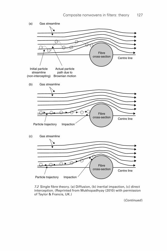
Composite nonwovens in fi lters: theory 127
7.2 Single fi bre theory. (a) Diffusion, (b) inertial impaction, (c) direct interception. (Reprinted from Mukhopadhyay (2010) with permission of Taylor & Francis, UK.)
(Continued )
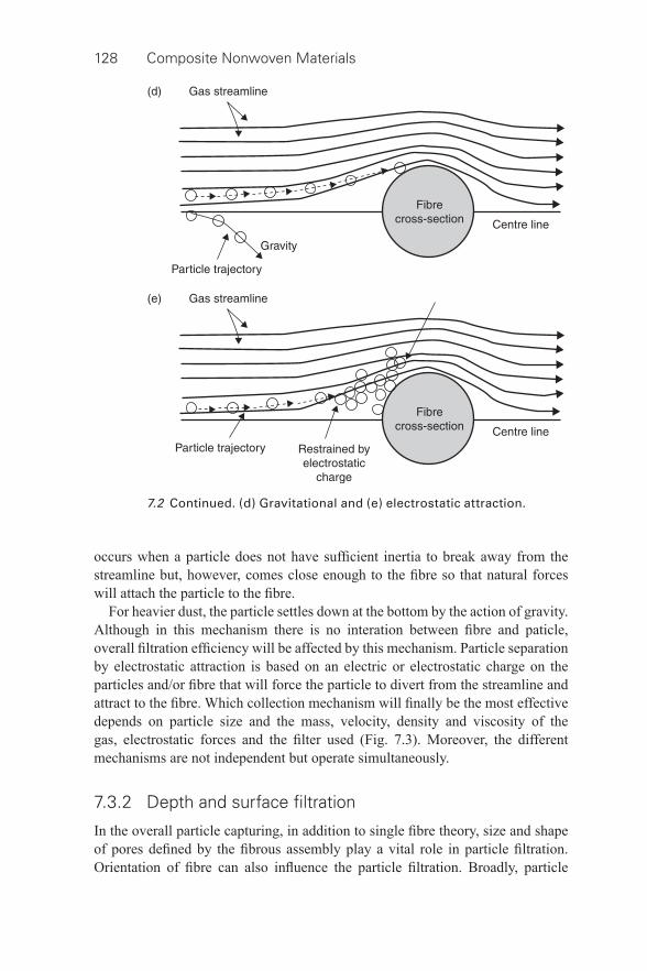
128 Composite Nonwoven Materials
occurs when a particle does not have suffi cient inertia to break away from the streamline but, however, comes close enough to the fi bre so that natural forces will attach the particle to the fi bre.
For heavier dust, the particle settles down at the bottom by the action of gravity. Although in this mechanism there is no interation between fi bre and paticle, overall fi ltration effi ciency will be affected by this mechanism. Particle separation by electrostatic attraction is based on an electric or electrostatic charge on the particles and/or fi bre that will force the particle to divert from the streamline and attract to the fi bre. Which collection mechanism will fi nally be the most effective depends on particle size and the mass, velocity, density and viscosity of the gas, electrostatic forces and the fi lter used ( Fig. 7.3 ). Moreover, the different mechanisms are not independent but operate simultaneously.
7.3.2 Depth and surface fi ltration
In the overall particle capturing, in addition to single fi bre theory, size and shape of pores defi ned by the fi brous assembly play a vital role in particle fi ltration. Orientation of fi bre can also infl uence the particle fi ltration. Broadly, particle
7.2 Continued. (d) Gravitational and (e) electrostatic attraction.
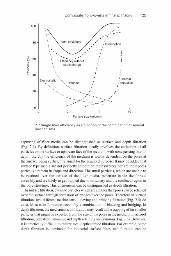
Composite nonwovens in fi lters: theory 129
7.3 Single fi bre effi ciency as a function of the combination of several mechanisms.
capturing of fi lter media can be distinguished as surface and depth fi ltration ( Fig. 7.4 ). By defi nition, surface fi ltration ideally involves the collection of all particles on the surface or upstream face of the medium, with none passing into its depth; thereby the effi ciency of the medium is totally dependent on the pores at the surface being suffi ciently small for the required purpose. It may be added that surface type media are not perfectly smooth on their surfaces nor are their pores perfectly uniform in shape and direction. The small particles, which are unable to be retained over the surface of the fi lter media, penetrate inside the fi brous assembly and are likely to get trapped due to tortuosity and the confi ned region in the pore structure. This phenomena can be distinguished as depth fi ltration.
In surface fi ltration, even the particles which are smaller than pores can be retained over the surface through formation of bridges over the pores. Therefore in surface fi ltration, two different mechanisms – sieving and bridging fi ltration ( Fig. 7.5 ) do exist. Most cake formation occurs by a combination of blocking and bridging. In depth fi ltration, the mechanisms of fi ltration may result in the trapping of far smaller particles that might be expected from the size of the pores in the medium. In aerosol fi ltration, both depth straining and depth retaining are common ( Fig. 7.6 ). However, it is practically diffi cult to realize total depth/surface fi ltration. For example, some depth fi ltration is inevitable for industrial surface fi lters and fi ltration can be
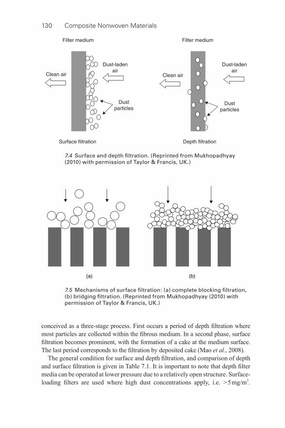
130 Composite Nonwoven Materials
7.5 Mechanisms of surface fi ltration: (a) complete blocking fi ltration, (b) bridging fi ltration. (Reprinted from Mukhopadhyay (2010) with permission of Taylor & Francis, UK.)
7.4 Surface and depth fi ltration. (Reprinted from Mukhopadhyay (2010) with permission of Taylor & Francis, UK.)
conceived as a three- stage process. First occurs a period of depth fi ltration where most particles are collected within the fi brous medium. In a second phase, surface fi ltration becomes prominent, with the formation of a cake at the medium surface. The last period corresponds to the fi ltration by deposited cake (Mao et al. , 2008).
The general condition for surface and depth fi ltration, and comparison of depth and surface fi ltration is given in Table 7.1. It is important to note that depth fi lter media can be operated at lower pressure due to a relatively open structure. Surface- loading fi lters are used where high dust concentrations apply, i.e. > 5 mg/m 3 .
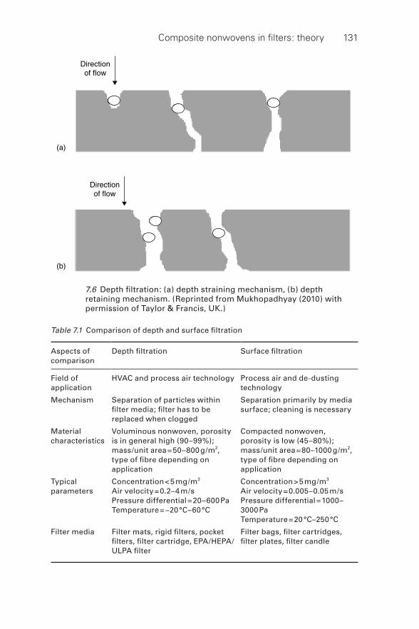
Composite nonwovens in fi lters: theory 131
7.6 Depth fi ltration: (a) depth straining mechanism, (b) depth retaining mechanism. (Reprinted from Mukhopadhyay (2010) with permission of Taylor & Francis, UK.)
Table 7.1 Comparison of depth and surface fi ltration
Aspects of comparison
Depth fi ltration Surface fi ltration
Field of application
HVAC and process air technology Process air and de- dusting technology
Mechanism Separation of particles within fi lter media; fi lter has to be replaced when clogged
Separation primarily by media surface; cleaning is necessary
Material characteristics
Voluminous nonwoven, porosity is in general high (90–99%); mass/unit area = 50–800 g/m 2 , type of fi bre depending on application
Compacted nonwoven, porosity is low (45–80%); mass/unit area = 80–1000 g/m 2 , type of fi bre depending on application
Typical parameters
Concentration < 5 mg/m 3 Air velocity = 0.2–4 m/s Pressure differential = 20–600 Pa Temperature = −20 °C–60 °C
Concentration > 5 mg/m 3 Air velocity = 0.005–0.05 m/s Pressure differential = 1000–3000 Pa Temperature = 20 °C–250 °C
Filter media Filter mats, rigid fi lters, pocket fi lters, fi lter cartridge, EPA/HEPA/ULPA fi lter
Filter bags, fi lter cartridges, fi lter plates, fi lter candle
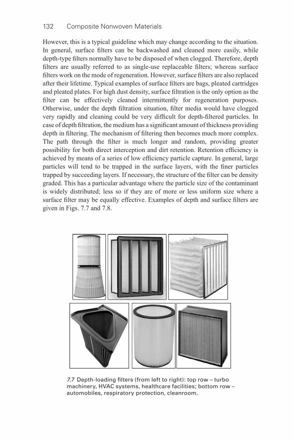
132 Composite Nonwoven Materials
7.7 Depth-loading fi lters (from left to right): top row – turbo machinery, HVAC systems, healthcare facilities; bottom row – automobiles, respiratory protection, cleanroom.
However, this is a typical guideline which may change according to the situation. In general, surface fi lters can be backwashed and cleaned more easily, while depth- type fi lters normally have to be disposed of when clogged. Therefore, depth fi lters are usually referred to as single- use replaceable fi lters; whereas surface fi lters work on the mode of regeneration. However, surface fi lters are also replaced after their lifetime. Typical examples of surface fi lters are bags, pleated cartridges and pleated plates. For high dust density, surface fi ltration is the only option as the fi lter can be effectively cleaned intermittently for regeneration purposes. Otherwise, under the depth fi ltration situation, fi lter media would have clogged very rapidly and cleaning could be very diffi cult for depth- fi ltered particles. In case of depth fi ltration, the medium has a signifi cant amount of thickness providing depth in fi ltering. The mechanism of fi ltering then becomes much more complex. The path through the fi lter is much longer and random, providing greater possibility for both direct interception and dirt retention. Retention effi ciency is achieved by means of a series of low effi ciency particle capture. In general, large particles will tend to be trapped in the surface layers, with the fi ner particles trapped by succeeding layers. If necessary, the structure of the fi lter can be density graded. This has a particular advantage where the particle size of the contaminant is widely distributed; less so if they are of more or less uniform size where a surface fi lter may be equally effective. Examples of depth and surface fi lters are given in Figs. 7.7 and 7.8 .
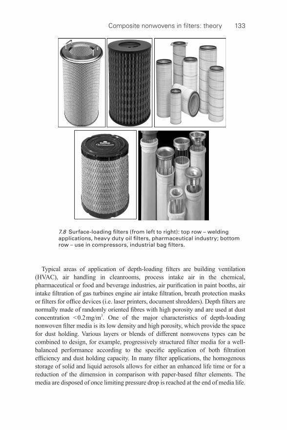
Composite nonwovens in fi lters: theory 133
Typical areas of application of depth- loading fi lters are building ventilation (HVAC), air handling in cleanrooms, process intake air in the chemical, pharmaceutical or food and beverage industries, air purifi cation in paint booths, air intake fi ltration of gas turbines engine air intake fi ltration, breath protection masks or fi lters for offi ce devices (i.e. laser printers, document shredders). Depth fi lters are normally made of randomly oriented fi bres with high porosity and are used at dust concentration < 0.2 mg/m 3 . One of the major characteristics of depth- loading nonwoven fi lter media is its low density and high porosity, which provide the space for dust holding. Various layers or blends of different nonwovens types can be combined to design, for example, progressively structured fi lter media for a well- balanced performance according to the specifi c application of both fi ltration effi ciency and dust holding capacity. In many fi lter applications, the homogenous storage of solid and liquid aerosols allows for either an enhanced life time or for a reduction of the dimension in comparison with paper- based fi lter elements. The media are disposed of once limiting pressure drop is reached at the end of media life.
7.8 Surface-loading fi lters (from left to right): top row – welding applications, heavy duty oil fi lters, pharmaceutical industry; bottom row – use in compressors, industrial bag fi lters.
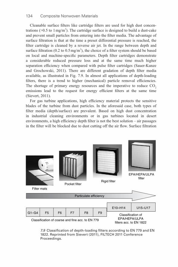
134 Composite Nonwoven Materials
Cleanable surface fi lters like cartridge fi lters are used for high dust concen-trations (>0.5 to 1 mg/m 3 ). The cartridge surface is designed to build a dust- cake and prevent small particles from entering into the fi lter media. The advantage of surface fi ltration is that at the time a preset differential pressure is reached, the fi lter cartridge is cleaned by a reverse air jet. In the range between depth and surface fi ltration (0.2 to 0.5 mg/m 3 ), the choice of a fi lter system should be based on local and machine-specifi c parameters. Depth fi lter cartridges demonstrate a considerable reduced pressure loss and at the same time much higher separation effi ciency when compared with pulse fi lter cartridges (Sauer-Kunze and Grochowski, 2011). There are different gradation of depth fi lter media available, as illustrated in Fig. 7.9 . In almost all applications of depth- loading fi lters, there is a trend to higher (mechanical) particle removal effi ciencies. The shortage of primary energy resources and the imperative to reduce CO 2 emissions lead to the request for energy effi cient fi lters at the same time (Sievert, 2011).
For gas turbine applications, high effi ciency material protects the sensitive blades of the turbine from dust particles. In the aforesaid case, both types of fi lter media (depth/surface) are prevalent. Based on high dust concentration in industrial cleaning environments or in gas turbines located in desert environments, a high effi ciency depth fi lter is not the best solution – air passages in the fi lter will be blocked due to dust cutting off the air fl ow. Surface fi ltration
7.9 Classifi cation of depth- loading fi lters according to EN 779 and EN 1822. Reprinted from Sievert (2011), FILTECH 2011 Conference Proceedings.
Composite nonwovens in fi lters: theory 135
is desired for collecting the dust on the surface of the fi lter because it creates a homogeneous, linear rise in pressure drop (Wertz and Schneiders, 2009).
It is important to note that liquid fi ltration mechanism is different from gas fi ltration as viscosity of liquid is much higher than that of gas. Primarily, the liquid–solid separation is dominated by the following three mechanisms:
• Screening or straining: particles are retained by the medium only as and when they are confronted with an aperture which is smaller than the particles themselves.
• Depth fi ltration: in this mechanism the particles are captured through attachment to the fi bres within the body of the fi lter medium.
• Cake fi ltration: once formed, the cake effectively becomes the fi lter medium with the fabric thereafter acting simply as a support. Cake fi ltration is most common in the case of surface fi lter media. In cases where it is diffi cult for the particles to form a naturally porous cake, the use of a special precoat or body feed may be employed to assist in this task.
Notwithstanding the fact that the fi lter fabric is used to effect the maximum separation of particles from liquids, absolute clarity is not always necessary. In certain gravity- or vacuum- assisted screening operations the fi lter fabric is simply designed to capture particles greater than a specifi c size and in other fi ltration systems a measure of solids in fi ltrate can be tolerated before cake fi ltration takes over and the necessary clarity is achieved. Recirculation of the slurry may also be possible in some applications until the same condition prevails. From this it will be appreciated that in some cases the solids are the more valuable component in the slurry, whereas in others the process is concerned with clarifi cation of the liquid, the solids thereafter being of little or no value.
7.3.3 Capture based on mode of fi ltration
There are many ways to defi ne the mode of fi ltration: cake vs. non- cake fi ltration, tangential vs. dead end fi ltration, fi ltration through electrostatic charging, etc. In case of cake fi ltration, the role of fabric becomes secondary once the cake is formed. In the industrial gas fi ltration process, the cleaning of fabric is performed either in reverse- jet or in pulse- jet air pressure. In the reverse- jet system, cake fi ltration is very prominent; whereas the pulse- jet fi ltration system is available in two different forms (cake fi ltration and non- cake fi ltration). It may be noted that the pulse- jet fi ltration process can be conceived as the most sustainable technology worldwide. During fi ltration, a positive effect is associated with greater fi ltration effi ciency due to cake fi ltration, and on the other hand, a negative effect is associated with increased pressure drop. Since industrial fi lters encounter high- dust density (more than 250 g/Nm 3 ), pressure drop increases steadily with time. Therefore, fi lter bags must be periodically regenerated either on the basis of a preset time interval or based on specifi ed pressure
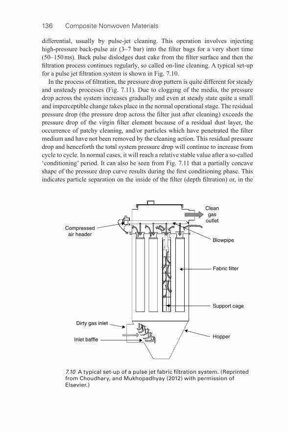
136 Composite Nonwoven Materials
differential, usually by pulse- jet cleaning. This operation involves injecting high- pressure back- pulse air (3–7 bar) into the fi lter bags for a very short time (50–150 ms). Back pulse dislodges dust cake from the fi lter surface and then the fi ltration process continues regularly, so called on- line cleaning. A typical set- up for a pulse jet fi ltration system is shown in Fig. 7.10 .
In the process of fi ltration, the pressure drop pattern is quite different for steady and unsteady processes ( Fig. 7.11 ). Due to clogging of the media, the pressure drop across the system increases gradually and even at steady state quite a small and imperceptible change takes place in the normal operational stage. The residual pressure drop (the pressure drop across the fi lter just after cleaning) exceeds the pressure drop of the virgin fi lter element because of a residual dust layer, the occurrence of patchy cleaning, and/or particles which have penetrated the fi lter medium and have not been removed by the cleaning action. This residual pressure drop and henceforth the total system pressure drop will continue to increase from cycle to cycle. In normal cases, it will reach a relative stable value after a so- called ‘conditioning’ period. It can also be seen from Fig. 7.11 that a partially concave shape of the pressure drop curve results during the fi rst conditioning phase. This indicates particle separation on the inside of the fi lter (depth fi ltration) or, in the
7.10 A typical set- up of a pulse jet fabric fi ltration system. (Reprinted from Choudhary, and Mukhopadhyay (2012) with permission of Elsevier.)
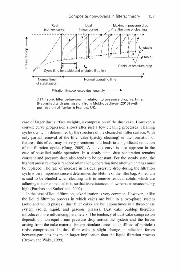
Composite nonwovens in fi lters: theory 137
case of larger dust surface weights, a compression of the dust cake. However, a convex curve progression shows after just a few cleaning processes (cleaning cycles), which is determined by the structure of the cleaned- off fi lter surface. With only partial removal of the fi lter cake (patchy cleaning) or the formation of fi ssures, this effect may be very prominent and leads to a signifi cant reduction of the fi ltration cycles (Gang, 2009). A convex curve is also apparent in the case of so- called stable operation. In a steady state, dust penetration remains constant and pressure drop also tends to be constant. For the steady state, the highest pressure drop is reached after a long operating time after which bags must be replaced. The rate of increase in residual pressure drop during the fi ltration cycle is very important since it determines the lifetime of the fi lter bag. A medium is said to be blinded when cleaning fails to remove residual solids, which are adhering to it or embedded in it, so that its resistance to fl ow remains unacceptably high (Purchas and Sutherland, 2002).
In the case of liquid fi ltration, cake fi ltration is very common. However, unlike the liquid fi ltration process in which cakes are built in a two- phase system (solid and liquid phases), dust fi lter cakes are built sometimes in a three- phase system (solid, liquid, and gaseous phases). Dust cake buildup therefore introduces more infl uencing parameters. The tendency of dust cake compression depends on non- equilibrium pressure drop across the system and the forces arising from the cake material (interparticulate forces and stiffness of particles) resist compression. In dust fi lter cake, a slight change in adhesion forces between particles has much larger implication than the liquid fi ltration process (Brown and Wake, 1999).
7.11 Fabric fi lter behaviour in relation to pressure drop vs. time. (Reprinted with permission from Mukhopadhyay (2010) with permission of Taylor & Francis, UK.)
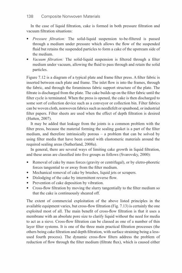
138 Composite Nonwoven Materials
In the case of liquid fi ltration, cake is formed in both pressure fi ltration and vacuum fi ltration situations:
• Pressure fi ltration: The solid- liquid suspension to- be-fi ltered is passed through a medium under pressure which allows the fl ow of the suspended fl uid but retains the suspended particles to form a cake of the upstream side of the medium.
• Vacuum fi ltration: The solid- liquid suspension is fi ltered through a fi lter medium under vacuum, allowing the fl uid to pass through and retain the solid particles.
Figure 7.12 is a diagram of a typical plate and frame fi lter press. A fi lter fabric is inserted between each plate and frame. The inlet fl ow is into the frames, through the fabric, and through the foraminous fabric support structure of the plate. The fi ltrate is discharged from the plate. The cake builds up on the fi lter fabric until the fi lter cycle is terminated. When the press is opened, the cake is then discharged to some sort of collection device such as a conveyor or collection bin. Filter fabrics can be woven cloth, nonwoven fabrics such as needlefelt or spunbond, or industrial fi lter papers. Filter sheets are used when the effect of depth fi ltration is desired (Hutten, 2007).
It may be added that leakage from the joints is a common problem with the fi lter press, because the material forming the sealing gasket is a part of the fi lter medium, and therefore intrinsically porous – a problem that can be solved by using fi lter media that have been coated with elastomeric materials around the required sealing areas (Sutherland, 2008a).
In general, there are several ways of limiting cake growth in liquid fi ltration, and these areas are classifi ed into fi ve groups as follows (Svarovsky, 2000):
• Removal of cake by mass forces (gravity or centrifugal), or by eletro- phoretic forces tangential to or away from the fi lter medium.
• Mechanical removal of cake by brushes, liquid jets or scrapers. • Dislodging of the cake by intermittent reverse fl ow. • Prevention of cake deposition by vibration. • Cross- fl ow fi ltration by moving the slurry tangentially to the fi lter medium so
that the cake is continuously sheared off.
The extent of commercial exploitation of the above listed principles in the available equipment varies, but cross- fl ow fi ltration ( Fig. 7.13 ) is certainly the one exploited most of all. The main benefi t of cross- fl ow fi ltration is that it uses a membrane with an absolute pore size to clarify liquid without the need for media to act as a sieve. Cross- fl ow fi ltration can be classed as one of a number of thin layer fi lter systems. It is one of the three main practical fi ltration processes (the others being cake fi ltration and depth fi ltration, with surface straining being a less- used fourth process). The dynamic cross- fl ow fi lters address the problem of reduction of fl ow through the fi lter medium (fi ltrate fl ux), which is caused either
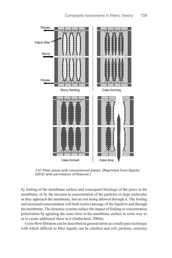
Composite nonwovens in fi lters: theory 139
by fouling of the membrane surface and consequent blockage of the pores in the membrane, or by the increase in concentration of the particles or large molecules as they approach the membrane, but are not being allowed through it. The fouling and increased concentration will both restrict passage of the liquid to and through the membrane. The dynamic systems reduce the impact of fouling or concentration polarization by agitating the zone close to the membrane surface in some way so as to create additional shear in it (Sutherland, 2008a).
Cross- fl ow fi ltration can be described in general terms as a multi- pass technique with which diffi cult to fi lter liquids can be clarifi ed and cell, proteins, enzymes
7.12 Filter press with conventional plates. (Reprinted from Sparks (2012) with permission of Elsevier.)
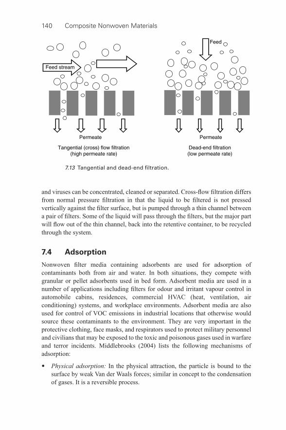
140 Composite Nonwoven Materials
and viruses can be concentrated, cleaned or separated. Cross- fl ow fi ltration differs from normal pressure fi ltration in that the liquid to be fi ltered is not pressed vertically against the fi lter surface, but is pumped through a thin channel between a pair of fi lters. Some of the liquid will pass through the fi lters, but the major part will fl ow out of the thin channel, back into the retentive container, to be recycled through the system.
7.4 Adsorption
Nonwoven fi lter media containing adsorbents are used for adsorption of contaminants both from air and water. In both situations, they compete with granular or pellet adsorbents used in bed form. Adsorbent media are used in a number of applications including fi lters for odour and irritant vapour control in automobile cabins, residences, commercial HVAC (heat, ventilation, air conditioning) systems, and workplace environments. Adsorbent media are also used for control of VOC emissions in industrial locations that otherwise would source these contaminants to the environment. They are very important in the protective clothing, face masks, and respirators used to protect military personnel and civilians that may be exposed to the toxic and poisonous gases used in warfare and terror incidents. Middlebrooks (2004) lists the following mechanisms of adsorption:
• Physical adsorption: In the physical attraction, the particle is bound to the surface by weak Van der Waals forces; similar in concept to the condensation of gases. It is a reversible process.
7.13 Tangential and dead- end fi ltration.
Composite nonwovens in fi lters: theory 141
• Chemical adsorption: A molecular species is attracted to a surface and reacts with that surface or something on that surface to form a chemical bond which holds it in place. Chemical adsorption is irreversible at constant conditions. Often the surface is impregnated with a chemical that promotes a desired reaction to remove specifi c contaminants.
• Catalysis: A molecular species is attracted to the surface which encourages a chemical reaction. The reaction product moves away leaving the surface unchanged. Typically, the reaction is considered irreversible.
One of the most prominent applications of adsorption principle is in the composite wherein a carbon layer is sandwiched between two nonwoven layers for removal of odour. The life of an adsorptive fi lter depends on the surface area and number of binding sites available. Once all the binding sites are exhausted, particles will pass right through the fi lter. Adsorptive fi lters do not exhibit any signifi cant increase in pressure drop with removal of particles.
7.5 Absorption
Absorption involves the taking of molecules of one substance directly into another substance. The process may either be physical or chemical. Physical absorption involves such factors as solubility and vapour- pressure relationships. Chemical absorption involves chemical reactions between the absorbed substance and the absorbing medium. Absoption is contrasted with adsorption in which the molecules adhere only to the surface of the second substance.
7.6 Coalescing
Coalescence is a process by which a fi lter medium can remove immiscible liquid particles from a liquid or gas stream. The fl uid can either be gas or liquid. This includes dispersed hydrocarbons from water, oil mists from air, moisture and vapour from air, and moisture from aviation fuel. The phenomenon is particulate fi ltration, in that it requires a matrix of fi ne fi bres to trap the liquid particles and hold them on the fi bres. An additional effect is provided for the transport of the entrapped liquid particles so that they can be removed from the media as a separate stream, either by fl otation or by a gravity settling mechanism.
Gas phase separations are used to separate moisture and/or oil mists from contaminated air streams. There are two different modes of gas phase separations (Hutten, 2007).
1 Separation of moisture from moisture laden air streams (demisters). 2 Separation of oil mists from air streams (compressed air operations, crank
case ventilation, lubricated machining, and cutting processes, etc).
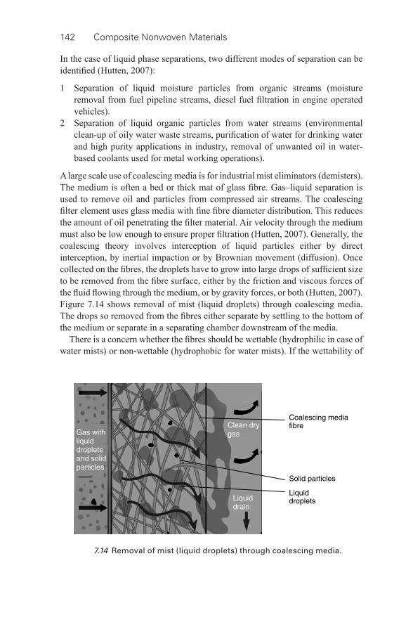
142 Composite Nonwoven Materials
In the case of liquid phase separations, two different modes of separation can be identifi ed (Hutten, 2007):
1 Separation of liquid moisture particles from organic streams (moisture removal from fuel pipeline streams, diesel fuel fi ltration in engine operated vehicles).
2 Separation of liquid organic particles from water streams (environmental clean- up of oily water waste streams, purifi cation of water for drinking water and high purity applications in industry, removal of unwanted oil in water- based coolants used for metal working operations).
A large scale use of coalescing media is for industrial mist eliminators (demisters). The medium is often a bed or thick mat of glass fi bre. Gas–liquid separation is used to remove oil and particles from compressed air streams. The coalescing fi lter element uses glass media with fi ne fi bre diameter distribution. This reduces the amount of oil penetrating the fi lter material. Air velocity through the medium must also be low enough to ensure proper fi ltration (Hutten, 2007). Generally, the coalescing theory involves interception of liquid particles either by direct interception, by inertial impaction or by Brownian movement (diffusion). Once collected on the fi bres, the droplets have to grow into large drops of suffi cient size to be removed from the fi bre surface, either by the friction and viscous forces of the fl uid fl owing through the medium, or by gravity forces, or both (Hutten, 2007). Figure 7.14 shows removal of mist (liquid droplets) through coalescing media. The drops so removed from the fi bres either separate by settling to the bottom of the medium or separate in a separating chamber downstream of the media.
There is a concern whether the fi bres should be wettable (hydrophilic in case of water mists) or non- wettable (hydrophobic for water mists). If the wettability of
7.14 Removal of mist (liquid droplets) through coalescing media.
Composite nonwovens in fi lters: theory 143
the fi bres is high, liquid droplets will form fi lm- wise collections on the fi bres. In an extreme case, the medium will become waterlogged resulting in high pressure drop, medium plugging, re- entrainment, and low separation effi ciency. On the other hand, if the fi bres are not wettable, the collection will be drop wise. If the surface energy is too low to hold the droplets to the fi bre surface, they will release and re- entrain into the fl uid stream (Hutten, 2007).
In recent years, water in oil emulsion separation has received greater attention. In many applications, dispersions of water drop sizes of less than 100 μ m diameter are very diffi cult to separate. The coalescence fi lter is economical and effective for separation of secondary dispersions (Shin and Chase, 2004). There are two very important and popular mechanisms to separate the liquid–liquid emulsions by means of porous media (Bansal et al. , 2011a):
1. Coalescence by means of depth fi lter: In this case, when the emulsion passes through the porous fi brous medium, the dispersed droplets adhere with the fi bres of the fi lter medium. These attached droplets further coalesce with one another within the fi lter. Depending on emulsion infl ow velocity and fi lter properties, these coalesced droplets leave the fi lter after attaining a certain size and are big enough to be separated by any mechanical or physical means.
2. Separation by means of surface fi lter: In this case, the emulsion passes through the porous fi brous medium of very small pore size and defi ned surface geometry (especially membranes). Therefore, the dispersed droplets are being retained at the fi lter surface and coalesce with one another there. Depending on emulsion infl ow velocity and adhesive forces of the dispersed phase with the fi lter surface, these coalesced droplets separate themselves from the fi lter surface either by gravitational or buoyancy forces.
Figure 7.15 shows deep fi ltration (coalescer) and surface fi ltration (separator) (Bansal et al. , 2011b). In both the cases, a steady state is reached, in which oil accumulation and drainage rates balance out. Filters operate in such a steady state for almost their entire life. Multi- layer fi lters are typically used in industry, and their performance depends largely on the nature of the fi lter (oleophobic/oleophilic) (Kampa et al. , 2011). Coalescence fi lter performance depends on fl ow rate of feed, drop sizes in the feed, and fi lter bed properties (pore size, surface wettability and porosity of the fi bre fi lters). Fibrous fi lter media provide the advantage of high fi ltration effi ciency at an economical energy cost. At a similar surface energy, the droplet capture effi ciency diminishes with increasing pore size and decreasing surface roughness of the fi lter. The coalescer should preferably be wetted by the dispersed phase to stimulate the droplet capture and coalescence. The emulsion separation effi ciency also depends on infl uent droplet size, drop residing time in the fi lter (which is a function of fi lter thickness, infl ow velocity and drop wettability at fi lter), fi bre fi neness and porosity of the fi lter (Bansal et al. , 2011a).
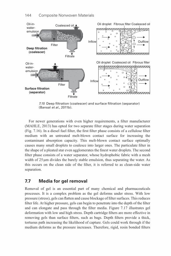
144 Composite Nonwoven Materials
For newer generations with even higher requirements, a fi lter manufacturer (MAHLE, 2013) has opted for two separate fi lter stages during water separation ( Fig. 7.16 ). In a diesel fuel fi lter, the fi rst fi lter phase consists of a cellulose fi lter medium with an untreated melt- blown contact surface for increasing the contaminant absorption capacity. This melt- blown contact surface optimally causes many small droplets to coalesce into larger ones. The particulate fi lter in the shape of a pleated star even agglomerates the fi nest water droplets. The second fi lter phase consists of a water separator, whose hydrophobic fabric with a mesh width of 25 μ m divides the barely stable emulsion, thus separating the water. As this occurs on the clean side of the fi lter, it is referred to as clean- side water separation.
7.7 Media for gel removal
Removal of gel is an essential part of many chemical and pharmaceuticals processes. It is a complex problem as the gel deforms under stress. With low pressure (stress), gels can fl atten and cause blockage of fi lter surfaces. This reduces fi lter life. At higher pressure, gels can begin to penetrate into the depth of the fi lter and can elongate and pass through the fi lter media. Figure 7.17 illustrates gel deformation with low and high stress. Depth cartridge fi lters are more effective in removing gels than surface fi lters, such as bags. Depth fi lters provide a thick, tortuous path increasing the likelihood of capture. Gels could work through if the medium deforms as the pressure increases. Therefore, rigid, resin bonded fi lters
7.15 Deep fi ltration (coalescer) and surface fi ltration (separator) (Bansal et al. , 2011b).
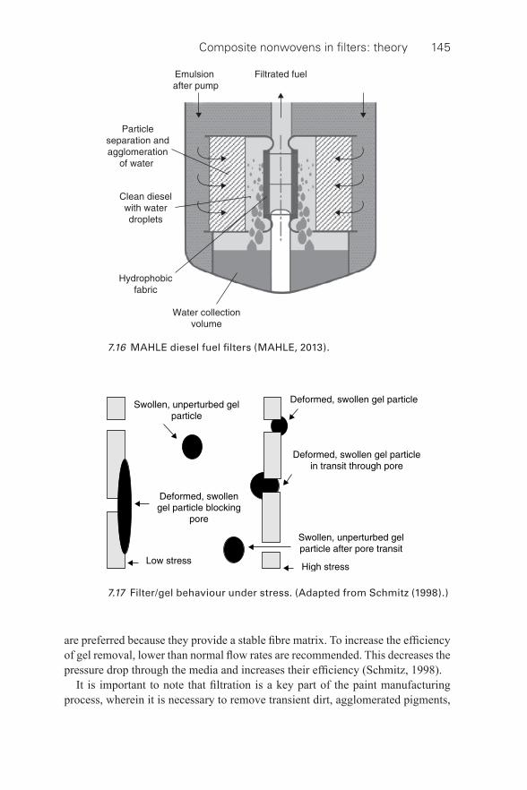
Composite nonwovens in fi lters: theory 145
7.16 MAHLE diesel fuel fi lters (MAHLE, 2013).
7.17 Filter/gel behaviour under stress. (Adapted from Schmitz (1998).)
are preferred because they provide a stable fi bre matrix. To increase the effi ciency of gel removal, lower than normal fl ow rates are recommended. This decreases the pressure drop through the media and increases their effi ciency (Schmitz, 1998).
It is important to note that fi ltration is a key part of the paint manufacturing process, wherein it is necessary to remove transient dirt, agglomerated pigments,
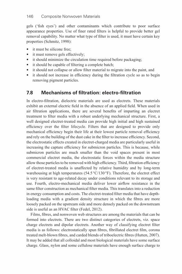
146 Composite Nonwoven Materials
gels (‘fi sh eyes’) and other contaminants which contribute to poor surface appearance properties. Use of fi ner rated fi lters is helpful to provide better gel removal capability. No matter what type of fi lter is used, it must have certain key properties (Schmitz, 1998):
• it must be silicone free; • it must remove gels effectively; • it should minimize the circulation time required before packaging; • it should be capable of fi ltering a complete batch; • it should not collapse or allow fi lter material to migrate into the paint, and • it should not increase in effi ciency during the fi ltration cycle so as to begin
removing pigment particles.
7.8 Mechanisms of fi ltration: electro- fi ltration
In electro- fi ltration, dielectric materials are used as electrets. These materials exhibit an external electric fi eld in the absence of an applied fi eld. When used in air fi ltration applications, there are several benefi ts of imparting an electret treatment to fi lter media with a robust underlying mechanical structure. First, a well designed electret- treated media can provide high initial and high sustained effi ciency over the fi lter lifecycle. Filters that are designed to provide only mechanical effi ciency begin their life at their lowest particle removal effi ciency and rely on the building of the dust cake in the fi lter to increase effi ciency. Second, the electrostatic effects created in electret- charged media are particularly useful in increasing the capture effi ciency for submicron particles. This is because, while submicron particles are much smaller than the void spaces present in most commercial electret media, the electrostatic forces within the media structure allow those particles to be removed with high effi ciency. Third, fi ltration effi ciency of electret- treated media is unaffected by relative humidity and by long- term warehousing at high temperatures (54.5 °C/130 °F). Therefore, the electret effect is very resistant to age- related decay under conditions relevant to its storage and use. Fourth, electro- mechanical media deliver lower airfl ow resistance in the same fi lter construction as mechanical fi lter media. This translates into a reduction in energy consumption and costs. The electret- treated fi lter media that have depth-loading media with a gradient density structure in which the fi bres are more loosely packed on the upstream side and more densely packed on the downstream side is useful as an HVAC fi lter (Fedel, 2012).
Films, fi bres, and nonwoven web structures are among the materials that can be formed into electrets. There are two distinct categories of electrets, viz. space charge electrets and dipolar electrets. Another way of classifying electret fi lter media is as follows: electrostatically spun fi bres, fi brillated electret fi lm, corona treated melt- blown fi bres, and carded blends of triboelectric fi bres (Hutten, 2007). It may be added that all colloidal and most biological materials have some surface charge. Glass, nylon and some cellulose materials have enough surface charge to
Composite nonwovens in fi lters: theory 147
attract and bind the particles to the fi bres. Nonwovens can be surface treated to produce or enhance the surface charge on the media. Charged cellulose media are good at reducing high particulate load from a fermentation process and colloidal material. Microfi breglass media are used as membrane pre- fi lters due to their high effi ciency and long life but have low colloid removal. Meltblown polypropylene media have moderate effi ciency and poor retention of colloids (Lydall Filtration and Separation, 2013). In the case of liquid fi ltration, the concept of electrokinetic fi ltration is prevalent wherein the medium is given a positive electronic charge that enables it to attract the mostly anionic particles in a polar fl uid stream. It is therefore effective in biopharmaceutical fi ltration due to the inherent charge on biological material.
7.9 Separation by antimicrobial media
Antimicrobial fi lter media consist of an agent to protect the fi lter by inhibiting the growth of bacteria, fungi, and yeast (Hutten, 2007). In some cases they are also intended to prevent the migration of biological microorganisms into the fi ltrate or fi ltered product. The antimicrobial agent can be applied to a medium as a fi nishing step or it can be incorporated into the fi bre. Antimicrobial activity in a fi lter medium serves the following basic purposes:
• It protects the fi lter and fi lter medium from biological decay and resulting failure.
• It can rapidly inactivate captured microorganisms and prevent further microbial growth inside the fi lter.
• It prevents the passage of biological organisms to the downstream environment of the fi lter.
7.10 Extraction
Extraction is a phenomenon that is not built into a fi lter medium, but rather the medium serves as a structural support for the extraction process. Teabag and tea fi lters act in a similar manner.
7.11 Key requirements for fi ltration media
For effective fi ltration, the fi lter medium has to be designed/selected based on the process gas/liquid requirements/application. In this regard, there could be wide variation in the type of fi bres and fabric structure based on applications. There are various requirements of media characteristics based on the following:
• fi ltration- specifi c requirements; • machine oriented requirements; • application oriented requirements.
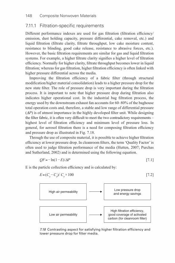
148 Composite Nonwoven Materials
7.11.1 Filtration-specifi c requirements
Different performance indexes are used for gas fi ltration (fi ltration effi ciency/emission, dust holding capacity, pressure differential, cake removal, etc.) and liquid fi ltration (fi ltrate clarity, fi ltrate throughput, low cake moisture content, resistance to blinding, good cake release, resistance to abrasive forces, etc.). However, the basic fi ltration requirements are similar for gas and liquid fi ltration systems. For example, a higher fi ltrate clarity signifi es a higher level of fi ltration effi ciency. Normally for higher clarity, fi ltrate throughput becomes lower in liquid fi ltration; whereas for gas fi ltration, higher fi ltration effi ciency is often linked with higher pressure differential across the media.
Improving the fi ltration effi ciency of a fabric fi lter (through structural modifi cation/higher material consolidation) leads to a higher pressure drop for the new state fi lter. The role of pressure drop is very important during the fi ltration process. It is important to note that higher pressure drop during fi ltration also indicates higher operational cost. In the industrial bag fi ltration process, the energy used by the downstream exhaust fan accounts for 60–80% of the baghouse total operation costs and, therefore, a stable and low range of differential pressure ( Δ P ) is of utmost importance in the highly developed fi lter unit. While designing the fi lter fabric, it is often very diffi cult to meet the two contradictory requirements – highest level of fi ltration effi ciency and minimum level of pressure loss. In general, for aerosol fi ltration there is a need for composing fi ltration effi ciency and pressure drop as illustrated in Fig. 7.18 .
Through the use of composite material, it is possible to achieve higher fi ltration effi ciency at lower pressure drop. In cleanroom fi lters, the term ‘Quality Factor’ is often used to judge fi ltration performance of the media (Hutten, 2007; Purchas and Sutherland, 2002) and is determined using the following equation.
QF = − ln(1 − E)/ Δ P [7.1]
E is the particle collection effi ciency and is calculated by:
E = (C u − C d )/ C u × 100 [7.2]
7.18 Contrasting aspect for satisfying higher fi ltration effi ciency and lower pressure drop for fi lter media.
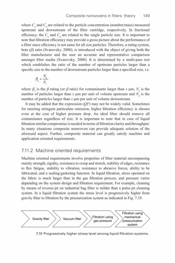
Composite nonwovens in fi lters: theory 149
where C u and C d are related to the particle concentration (number/mass) measured upstream and downstream of the fi lter cartridge, respectively. In fractional effi ciency, the C u and C d are related to the single particle size. It is important to note that fi ltration effi ciency may provide a gross picture about the performance of a fi lter since effi ciency is not same for all size particles. Therefore, a rating system, beta ( β ) ratio (Svarovsky, 2000), is introduced with the object of giving both the fi lter manufacturer and the user an accurate and representative comparison amongst fi lter media (Svarovsky, 2000). It is determined by a multi- pass test which establishes the ratio of the number of upstream particles larger than a specifi c size to the number of downstream particles larger than a specifi ed size, i.e.
where β x is the β rating (or β ratio) for contaminants larger than x μ m, N u is the number of particles larger than x μ m per unit of volume upstream and N d is the number of particles larger than x μ m per unit of volume downstream.
It may be added that the expression (QF) may not be widely valid. Sometimes for meeting stringent particulate emission, higher fi ltration effi ciency is chosen even at the cost of higher pressure drop. An ideal fi lter should remove all contaminates regardless of size. It is important to note that in case of liquid fi ltration similar compromise is needed in terms of fi ltration clarity and throughput. In many situations composite nonwoven can provide adequate solution of the aforesaid aspect. Further, composite material can greatly satisfy machine and application oriented requirements.
7.11.2 Machine oriented requirements
Machine oriented requirements involve properties of fi lter material encompassing mainly strength, rigidity, resistance to creep and stretch, stability of edges, resistance to fl ex fatigue, stability to vibration, resistance to abrasive forces, ability to be fabricated, and a sealing/gasketing function. In liquid fi ltration, stress operated on the fabric is much larger than in the gas fi ltration process, and pressure varies depending on the system design and fi ltration requirement. For example, cleaning by means of reverse- jet on industrial bag fi lter is milder than a pulse- jet cleaning system. In a liquid fi ltration system the stress level is progressively higher from gravity fi lter to fi ltration by the pressurization system as indicated in Fig. 7.19 .
7.19 Progressively higher stress level among liquid fi ltration systems.
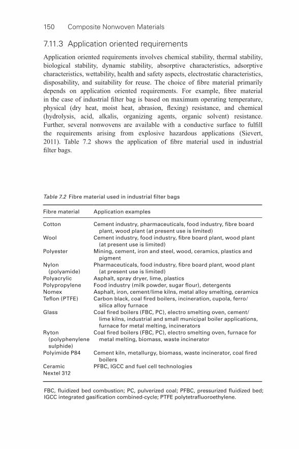
150 Composite Nonwoven Materials
7.11.3 Application oriented requirements
Application oriented requirements involves chemical stability, thermal stability, biological stability, dynamic stability, absorptive characteristics, adsorptive characteristics, wettability, health and safety aspects, electrostatic characteristics, disposability, and suitability for reuse. The choice of fi bre material primarily depends on application oriented requirements. For example, fi bre material in the case of industrial fi lter bag is based on maximum operating temperature, physical (dry heat, moist heat, abrasion, fl exing) resistance, and chemical (hydrolysis, acid, alkalis, organizing agents, organic solvent) resistance. Further, several nonwovens are available with a conductive surface to fulfi ll the requirements arising from explosive hazardous applications (Sievert, 2011). Table 7.2 shows the application of fi bre material used in industrial fi lter bags.
Table 7.2 Fibre material used in industrial fi lter bags
Fibre material Application examples
Cotton Cement industry, pharmaceuticals, food industry, fi bre board plant, wood plant (at present use is limited)
Wool Cement industry, food industry, fi bre board plant, wood plant (at present use is limited)
Polyester Mining, cement, iron and steel, wood, ceramics, plastics and pigment
Nylon (polyamide)
Pharmaceuticals, food industry, fi bre board plant, wood plant (at present use is limited)
Polyacrylic Asphalt, spray dryer, lime, plastics Polypropylene Food industry (milk powder, sugar fl our), detergents Nomex Asphalt, iron, cement/lime kilns, metal alloy smelting, ceramics Tefl on (PTFE) Carbon black, coal fi red boilers, incineration, cupola, ferro/
silica alloy furnace Glass Coal fi red boilers (FBC, PC), electro smelting oven, cement/
lime kilns, industrial and small municipal boiler applications, furnace for metal melting, incinerators
Ryton (polyphenylene sulphide)
Coal fi red boilers (FBC, PC), electro smelting oven, furnace for metal melting, biomass, waste incinerator
Polyimide P84 Cement kiln, metallurgy, biomass, waste incinerator, coal fi red boilers
Ceramic Nextel 312
PFBC, IGCC and fuel cell technologies
FBC, fl uidized bed combustion; PC, pulverized coal; PFBC, pressurized fl uidized bed; IGCC integrated gasifi cation combined- cycle; PTFE polytetrafl uoroethylene.
Composite nonwovens in fi lters: theory 151
7.12 Characteristics of nonwoven fi lters
Textile fi lter media have proved to be superior in many applications of gas and liquid fi ltration. In many cases the performance requirement can only be satisfi ed with textile fi lter media, among which the use of nonwovens is most prominent. In general, the nonwoven fi lter media can be grouped according to the following considerations:
• surface fi lters (cleanable) or depth fi lters (storage fi lters); • the nature of the surrounding medium (dry and wet fi ltration); • particle size to be fi ltered (e.g. micro-, ultra- fi ltration).
The fi rst major distinction between the items listed above is whether the fi lter media or manufactured fi lters are single use, essentially storage fi lters, or whether they are cleanable and capable of regeneration by a backwash/reverse fl ow, shake or mechanical fi lter cake removal process. Synthetic fi bre nonwovens have dominated the fi ltration industry since the 1970s because of fi ve basic advantages (Scoble, 2011):
• performance in effi ciency, pressure differential, durability and adaptability; • high volume, low cost production processes producing lower cost media
(compared to woven fabric); • possibilities in achieving wide structural variability at ease (e.g., weight,
permeability, surface characteristics, widths, and other basic characteristics); • pleatability/moldability of material; • availability (most serve multiple market segments).
In nonwoven fabric, fi ltration effi ciency is quite high due to the role of constituent fi bre (individual fi bre acts as a fi lter element) and nature of fi bre consolidation. Further, for similar application, total porosity of nonwoven fi lter media could be quite large as compared to woven fabric. For industrial fi lter bag, the porosity of surface fi lter media is between 70 and 80%, which is almost double that of woven fabric fi lter media (30–40%). This results in a lower pressure differential across nonwoven fi lter media. Further, special nonwoven structures can achieve three times more airfl ow than woven fi lters (Yang et al. , 2002). This implies a smaller size of fi lter unit and also lower fan energy consumption. In depth fi ltration application, tortuous and interconnected pores in nonwoven helps in better media performance in capturing solid particles.
A variety of nonwoven fi lter media can be produced with different man-ufacturing methods (e.g., needlepunching, spunbonding, meltblowing, spunlacing, etc.), laying techniques (e.g., wet lay, dry lay) and varying fi bre type (e.g., glass fi bre, polyester fi bre), with their fi neness ranging from the macro- to the nano- scale. Specifi cally, fi bre diameter has a signifi cant infl uence on the performance of the fi lter media. Nonwovens can feature characteristics such as chemical and water resistance, oil repellent, reduced fl ammability or fi re blocking, electrical conductivity for usage in an explosive environment, preventing microbial growth,
152 Composite Nonwoven Materials
being biodegradable and many more. This allows nonwovens to meet the increasing requirements from environmental legislation and from new safety standards. From the use of polymer fi bres it is possible to heat weld or ultrasonically weld nonwovens allowing modern technologies to be used to manufacture fi lter elements such as pocket fi lters, cartridge fi lters and cassette type fi lters. The true engineering of the nonwoven fabrics gives them the chance to be incorporated in many types of fi lters, e.g. from coarse fi lter mats (fi lter class G1–G4) to high effi cient HEPA fi lters (fi lter class H10–H14) (Sievert, 2011).
Although widely used in dust collection, needlefelts have found only limited use in liquid fi ltration because their thickness and density render them prone to blinding in many applications. However, they are found useful in some niche areas, e.g. fi ltration of metal ore concentrates such as copper on horizontal vacuum belt fi lters. These applications tend to be very aggressive on the fi lter fabric, and hence a suitably designed and fi nished needlefelt is often more cost effective than a considerably more expensive woven fabric. For such arduous applications, needlefelts are generally in the area density range 800–1000 gm −2 . However, the uses of nonwovens in many liquid fi ltration applications are increasing in a steady manner. In general the growth of nonwovens over the last four decades is infl uenced by the following factors:
• the growth of a wide range of nonwoven processes; • adaptation of nonwovens designed for other markets into fi ltration (e.g.,
spunbonded, spunlaced nonwovens); • growth of pulse- jet collectors using needled felts vs shaker collectors using
woven fabric; • evolution of needling processes from scrim supported to self supported; • expansion of pleated cartridges, pleated bags and fi lter elements into new fi ltration segments;
• application of membrane laminates effectively repurposed, less effi cient nonwovens into high effi ciency media (reverse osmosis, pleated cartridges, dust bags);
• environmental legislation forcing the use of more fi ltration equipment (1970, 1990, present day);
• development of micro-fi bres and nano- fi bres.
7.13 Types of nonwoven fi lter
7.13.1 Single- use replaceable fi lters
The largest use of nonwoven fi lter media is in single- use replaceable fi lter elements. Mostly, the fi lter material functions as a depth fi lter media. Three types of replaceable fi lter elements can be identifi ed:
• panel, pocket, cassette and pleated cartridge fi lters for air fi ltration;
Composite nonwovens in fi lters: theory 153
• bag fi lters for liquid fi ltration; • cartridge fi lters for liquid fi ltration.
All these fi lter media are not regenerated during the process of fi ltration. It may be added that bag fi lters are in general designed for applications with a desired fi ltration rate from 1 to 1000 micron; whereas cartridge fi lters have a fi ltration rate from 0.1 up to 500 micron. However, in situation, a fi lter bag can work better than a fi lter cartridge. Nonwoven fabric with progressive density (PROGAF’s) (Eaton, 2013) delivers high effi ciency (>99.98%) through depth fi ltration, and long life with all the convenient features of a bag fi lter.
In comparison with other fi ltration technologies, fi lter media deliver lower operating costs while retaining the ease of change- out typical of a bag fi lter. Apart from the above, many other forms of fi lter are also used, such as a roll fi lter. Roll fi lters come in a variety of shapes and mechanisms (deep bed fi lters/pressure fi ltration systems). It may also be added that fi lter presses (mechanical pressurization systems) and belt fi lters (vaccum fi lters) account for a large proportion of the world’s solid–liquid fi ltration activity, and have developed to become larger, more sophisticated and also more reliable. They are now found in applications ranging from small- scale, ultra clean medical laboratory applications to the largest, dustiest and heaviest applications of fi ltration. However, in these fi lters the use of nonwoven is restricted; but can have a potential future.
The disposable cartridge or element is one that is suffi ciently inexpensive, so that any attempt to clean and reuse the cartridge would not be economically justifi ed. Depth fi lter cartridges usually cannot be readily cleansed since the dirt is so well entrapped in the medium that cleansing would provide little benefi t in restoring the cartridge for reuse. Eventually, even cleanable cartridges will have to be replaced. It is important to note that dirt- holding capacity is an important requirement for fi lter cartridges (Hutten, 2007). Ways to increase dirt holding capacity are shown in the following (Hutten, 2007). • Increase the surface area of the medium: Pleating is the most popular way of
increasing the surface area of a medium. It may be added that corrugation and, to a lesser degree, creping enhances the surface area of a fi lter medium.
• Use a prefi lter: Prefi lters would fi lter out the relatively coarse particles before
the fi nal fi ltration. There are fi lter designs where the prefi lter medium and the fi nal fi lter medium are contained within the same fi lter housing.
• Gradient density fi lter media: Gradient density media have a change in density
as the fl ow passes from the upstream surface to the downstream surface. The change in density allows for a form of depth fi ltration so that larger particles are removed at the low density upstream surface and fi ner particles are
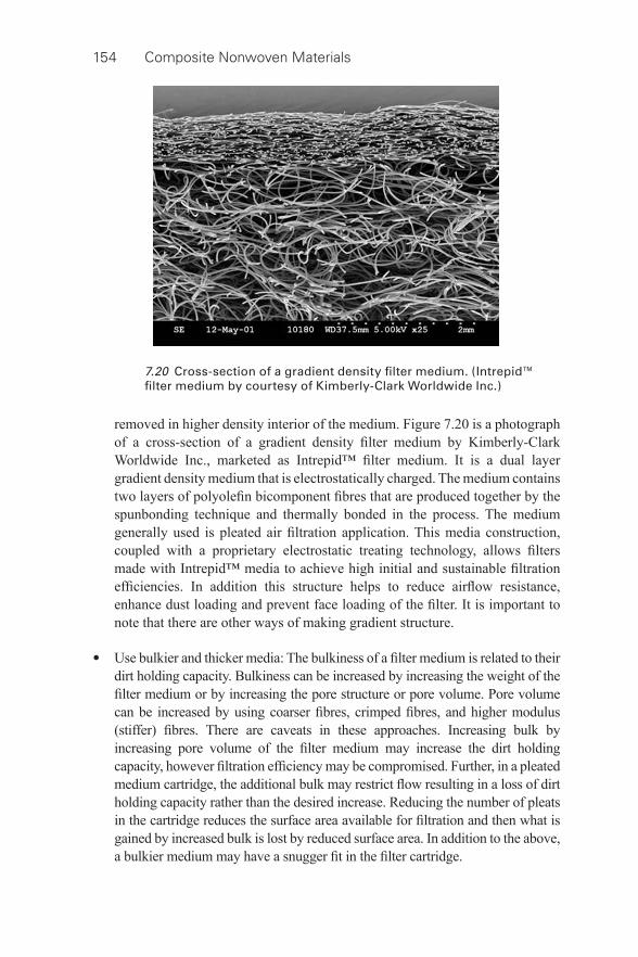
154 Composite Nonwoven Materials
removed in higher density interior of the medium. Figure 7.20 is a photograph of a cross- section of a gradient density fi lter medium by Kimberly-Clark Worldwide Inc., marketed as Intrepid™ fi lter medium. It is a dual layer gradient density medium that is electrostatically charged. The medium contains two layers of polyolefi n bicomponent fi bres that are produced together by the spunbonding technique and thermally bonded in the process. The medium generally used is pleated air fi ltration application. This media construction, coupled with a proprietary electrostatic treating technology, allows fi lters made with Intrepid™ media to achieve high initial and sustainable fi ltration effi ciencies. In addition this structure helps to reduce airfl ow resistance, enhance dust loading and prevent face loading of the fi lter. It is important to note that there are other ways of making gradient structure.
• Use bulkier and thicker media: The bulkiness of a fi lter medium is related to their
dirt holding capacity. Bulkiness can be increased by increasing the weight of the fi lter medium or by increasing the pore structure or pore volume. Pore volume can be increased by using coarser fi bres, crimped fi bres, and higher modulus (stiffer) fi bres. There are caveats in these approaches. Increasing bulk by increasing pore volume of the fi lter medium may increase the dirt holding capacity, however fi ltration effi ciency may be compromised. Further, in a pleated medium cartridge, the additional bulk may restrict fl ow resulting in a loss of dirt holding capacity rather than the desired increase. Reducing the number of pleats in the cartridge reduces the surface area available for fi ltration and then what is gained by increased bulk is lost by reduced surface area. In addition to the above, a bulkier medium may have a snugger fi t in the fi lter cartridge.
7.20 Cross- section of a gradient density fi lter medium. (Intrepid™ fi lter medium by courtesy of Kimberly-Clark Worldwide Inc.)
Composite nonwovens in fi lters: theory 155
• Use of charged media: Use of electrets in the air fi ltration process is useful for
greater dust holding. They are disposable and priced higher than fi breglass and pleated fi lters but less than washable/reusable fi lters. Their recommended replacement life is three months during seasons of normal use. In liquid fi ltration, molecules carrying a positive (cationic) charge are chemically bonded to the matrix components to form an interconnected, rigid fi lter sheet with positively charged electrokinetic capture sites. Since most contaminants found in fl uid streams are negatively charged (anionic), they will be inherently attracted to the positive sites on the medium. The results in improved effi ciency and dirt holding capacity. The Zeta Plus® media (composed of fi lter aids embedded in a cellulose fi bre matrix) are used in a variety of industrial liquid fi lter applications, including pharmaceutical and bio- processing separations.
Panel, pocket and cassette fi lters
Air fi lters for cleanrooms are available in different forms and are named as pleated panel fi lters, pocket fi lters, extended surface v- style fi lters, cassette fi lters, pleated cartridge fi lters, etc. Square or rectangular panel fi lters are the most frequently used for air cleaning systems in the domestic residences and in the work place. Broadly, there are six main categories of in- duct air cleaning devices for residential air handling systems such as fi breglass fi lters, pleated fi lters, washable/reusable fi lters, electret fi lters, deep pleated fi lters and electronic air cleaners. Textile media are used in all cases except electronic air cleaners. For stricter requirement, HEPA/ULPA fi lters are used.
Cleanroom manufacturers pay strict attention to air particles, with most cleanroom design and manufacturing companies targeting the elimination of air particles 0.5 μ m in size or larger, which has been generally the function of cleanroom air fi lters. However, some industries are now imposing even smaller air particle standards. Most indoor air pollution comes from the hazardous non- biological agents and biological agents. The cleanroom system must thus reduce the contamination entering with the air drawn into the room, and also remove that produced within the room to a suitable level to match the requirements of the processes being undertaken (Sutherland, 2008b). For applications in cartridge fi lters, extremely thin and stiff nonwovens are used. The thickness of these fi lter media varies between 0.1 and 5 mm and their basis weight is lower than for tube fi lters. They also have a paper- like appearance because they are mostly wetlaid and spunlaced. These fi lters are pleated and folded in a star form which helps to provide higher fi lter stiffness and higher fi lter surface area. This in turn works positively towards the pressure drop (lower pressure drop).
Filters designed for the treatment of air fall broadly into three categories (Sutherland, 2008a):
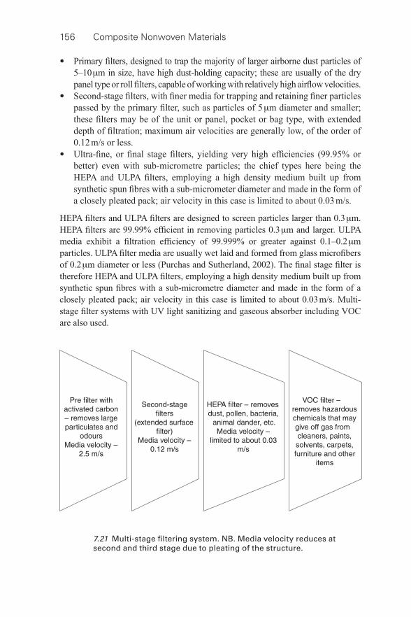
156 Composite Nonwoven Materials
• Primary fi lters, designed to trap the majority of larger airborne dust particles of 5–10 μ m in size, have high dust- holding capacity; these are usually of the dry panel type or roll fi lters, capable of working with relatively high airfl ow velocities.
• Second- stage fi lters, with fi ner media for trapping and retaining fi ner particles passed by the primary fi lter, such as particles of 5 μ m diameter and smaller; these fi lters may be of the unit or panel, pocket or bag type, with extended depth of fi ltration; maximum air velocities are generally low, of the order of 0.12 m/s or less.
• Ultra- fi ne, or fi nal stage fi lters, yielding very high effi ciencies (99.95% or better) even with sub- micrometre particles; the chief types here being the HEPA and ULPA fi lters, employing a high density medium built up from synthetic spun fi bres with a sub- micrometer diameter and made in the form of a closely pleated pack; air velocity in this case is limited to about 0.03 m/s.
HEPA fi lters and ULPA fi lters are designed to screen particles larger than 0.3 μ m. HEPA fi lters are 99.99% effi cient in removing particles 0.3 μ m and larger. ULPA media exhibit a fi ltration effi ciency of 99.999% or greater against 0.1–0.2 μ m particles. ULPA fi lter media are usually wet laid and formed from glass microfi bers of 0.2 μ m diameter or less (Purchas and Sutherland, 2002). The fi nal stage fi lter is therefore HEPA and ULPA fi lters, employing a high density medium built up from synthetic spun fi bres with a sub- micrometre diameter and made in the form of a closely pleated pack; air velocity in this case is limited to about 0.03 m/s. Multi- stage fi lter systems with UV light sanitizing and gaseous absorber including VOC are also used.
7.21 Multi- stage fi ltering system. NB. Media velocity reduces at second and third stage due to pleating of the structure.
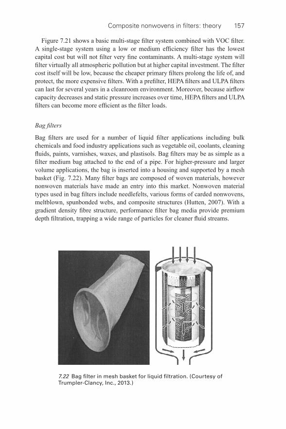
Composite nonwovens in fi lters: theory 157
Figure 7.21 shows a basic multi- stage fi lter system combined with VOC fi lter. A single- stage system using a low or medium effi ciency fi lter has the lowest capital cost but will not fi lter very fi ne contaminants. A multi- stage system will fi lter virtually all atmospheric pollution but at higher capital investment. The fi lter cost itself will be low, because the cheaper primary fi lters prolong the life of, and protect, the more expensive fi lters. With a prefi lter, HEPA fi lters and ULPA fi lters can last for several years in a cleanroom environment. Moreover, because airfl ow capacity decreases and static pressure increases over time, HEPA fi lters and ULPA fi lters can become more effi cient as the fi lter loads.
Bag fi lters
Bag fi lters are used for a number of liquid fi lter applications including bulk chemicals and food industry applications such as vegetable oil, coolants, cleaning fl uids, paints, varnishes, waxes, and plastisols. Bag fi lters may be as simple as a fi lter medium bag attached to the end of a pipe. For higher- pressure and larger volume applications, the bag is inserted into a housing and supported by a mesh basket ( Fig. 7.22 ). Many fi lter bags are composed of woven materials, however nonwoven materials have made an entry into this market. Nonwoven material types used in bag fi lters include needlefelts, various forms of carded nonwovens, meltblown, spunbonded webs, and composite structures (Hutten, 2007). With a gradient density fi bre structure, performance fi lter bag media provide premium depth fi ltration, trapping a wide range of particles for cleaner fl uid streams.
7.22 Bag fi lter in mesh basket for liquid fi ltration. (Courtesy of Trumpler-Clancy, Inc., 2013.)
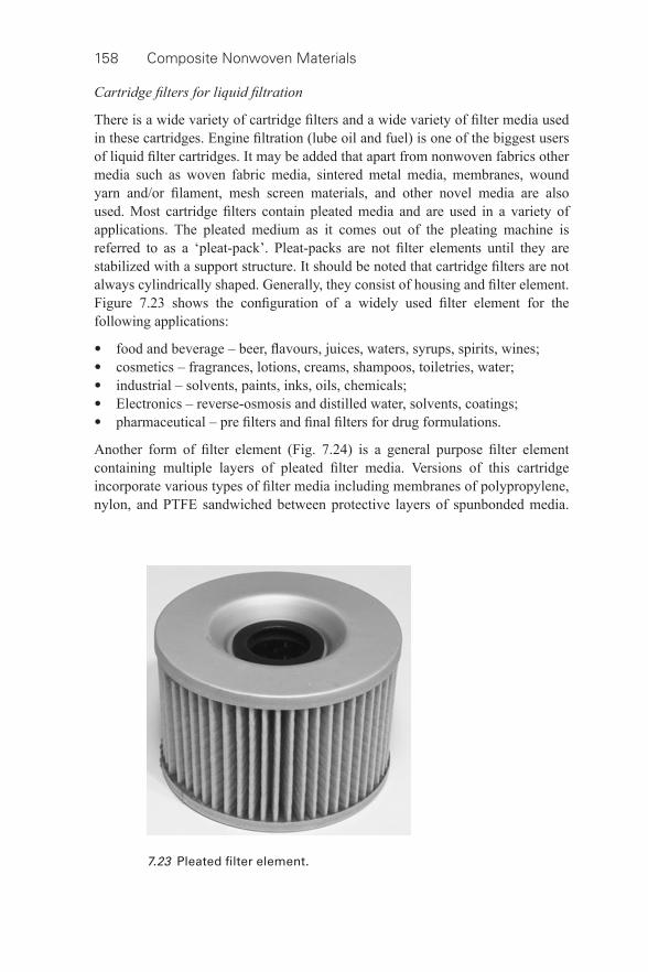
158 Composite Nonwoven Materials
Cartridge fi lters for liquid fi ltration
There is a wide variety of cartridge fi lters and a wide variety of fi lter media used in these cartridges. Engine fi ltration (lube oil and fuel) is one of the biggest users of liquid fi lter cartridges. It may be added that apart from nonwoven fabrics other media such as woven fabric media, sintered metal media, membranes, wound yarn and/or fi lament, mesh screen materials, and other novel media are also used. Most cartridge fi lters contain pleated media and are used in a variety of applications. The pleated medium as it comes out of the pleating machine is referred to as a ‘pleat- pack’. Pleat- packs are not fi lter elements until they are stabilized with a support structure. It should be noted that cartridge fi lters are not always cylindrically shaped. Generally, they consist of housing and fi lter element. Figure 7.23 shows the confi guration of a widely used fi lter element for the following applications:
• food and beverage – beer, fl avours, juices, waters, syrups, spirits, wines; • cosmetics – fragrances, lotions, creams, shampoos, toiletries, water; • industrial – solvents, paints, inks, oils, chemicals; • Electronics – reverse- osmosis and distilled water, solvents, coatings; • pharmaceutical – pre fi lters and fi nal fi lters for drug formulations.
Another form of fi lter element ( Fig. 7.24 ) is a general purpose fi lter element containing multiple layers of pleated fi lter media. Versions of this cartridge incorporate various types of fi lter media including membranes of polypropylene, nylon, and PTFE sandwiched between protective layers of spunbonded media.
7.23 Pleated fi lter element.
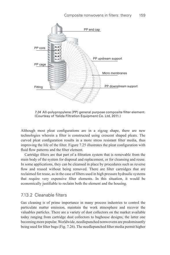
Composite nonwovens in fi lters: theory 159
7.24 All-polypropylene (PP) general purpose composite fi lter element. (Courtesy of Yalida Filtration Equipment Co. Ltd, 2011.)
Although most pleat confi gurations are in a zigzag shape, there are new technologies wherein a fi lter is constructed using crescent shaped pleats. The curved pleat confi guration results in a more stress resistant fi lter media, thus improving the life of the fi lter. Figure 7.25 illustrates the pleat confi guration with fl uid fl ow patterns and the fi lter element.
Cartridge fi lters are that part of a fi ltration system that is removable from the main body of the system for disposal and replacement, or for cleansing and reuse. In some applications, they can be cleansed in place by procedures such as reverse fl ow and reused without being removed. There are fi lter cartridges that are reclaimed for reuse, as in the case of fi lters used in high pressure hydraulic systems that require very expensive fi lter elements. In this situation, it would be economically justifi able to reclaim both the element and the housing.
7.13.2 Cleanable fi lters
Gas cleaning is of prime importance in many process industries to control the particulate matter emission, maintain the work atmosphere and recover the valuables particles. There are a variety of dust collectors on the market available today ranging from cartridge dust collectors to baghouse designs; the latter one becoming more popular. Worldwide, needlepunched nonwovens are predominantly being used for fi lter bags ( Fig. 7.26 ). The needlepunched fi lter media permit higher
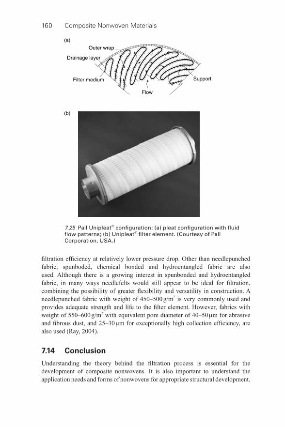
160 Composite Nonwoven Materials
fi ltration effi ciency at relatively lower pressure drop. Other than needlepunched fabric, spunboded, chemical bonded and hydroentangled fabric are also used. Although there is a growing interest in spunbonded and hydroentangled fabric, in many ways needlefelts would still appear to be ideal for fi ltration, combining the possibility of greater fl exibility and versatility in construction. A needlepunched fabric with weight of 450–500 g/m 2 is very commonly used and provides adequate strength and life to the fi lter element. However, fabrics with weight of 550–600 g/m 2 with equivalent pore diameter of 40–50 μ m for abrasive and fi brous dust, and 25–30 μ m for exceptionally high collection effi ciency, are also used (Ray, 2004).
7.14 Conclusion
Understanding the theory behind the fi ltration process is essential for the development of composite nonwovens. It is also important to understand the application needs and forms of nonwovens for appropriate structural development.
7.25 Pall Unipleat® confi guration: (a) pleat confi guration with fl uid fl ow patterns; (b) Unipleat® fi lter element. (Courtesy of Pall Corporation, USA.)
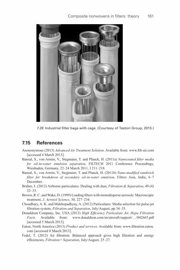
Composite nonwovens in fi lters: theory 161
7.15 References
Anononymous ( 2013 ) Advanced Air Treatment Solution . Available from: www.fi lt- air.com [accessed 4 March 2013 ].
Bansal , S. , von Armin , V. , Stegmaier , T. and Planck , H. ( 2011 a) Nanocoated fi lter media for oil- in-water emulsion separation , FILTECH 2011 Conference Proceedings, Wiesbaden , Germany, 22 – 24 March 2011 , I 211 – 218 .
Bansal , S. , von Armin , V. , Stegmaier , T. and Planck , H. ( 2011 b) Nano- modifi ed sandwich fi lter for breakdown of secondary oil- in-water emulsion , Filtrex Asia , India , 6 – 7 December .
Brahm , J. ( 2012 ) Airborne particulates: Dealing with dust , Filtration & Separation , 49 ( 4 ) 32 – 33 .
Brown , R. C. and Wake , D. ( 1999 ) Loading fi lters with monodisperse aerosols: Macroscopic treatment , J. Aerosol Science , 30 , 227 – 234 .
Choudhary , A. K. and Mukhopadhyay , A. ( 2012 ) Particulates: Media selection for pulse- jet fi ltration system , Filtration and Separation , July / August , pp 34 – 35 .
Donaldson Company, Inc. USA ( 2013 ) High Effi ciency Particulate Air, Hepa Filtration Facts . Available from: www.donaldson.com/en/aircraft/support/. . ./042665.pdf [accessed 5 March 2013 ].
Eaton, North America ( 2013 ) Product and services . Available from: www.fi ltration.eaton.com [accessed 8 March 2013 ].
Fedel , T. ( 2012 ) Air fi ltration: Balanced approach gives high fi ltration and energy effi ciencies , Filtration + Separation , July / August , 25 – 27 .
7.26 Industrial fi lter bags with cage. (Courtesy of Testori Group, 2013.)
162 Composite Nonwoven Materials
Gang , P. ( 2009 ) Testing and selection of fi lter media for dedusting, Part 2: Field measurements with a mobile fi lter probe derived from VDI/DIN 3926 , Filtration & Separation (International Edition), No. 9 , 17 – 23 .
Hutten , I. M. ( 2007 ) Handbook of Nonwoven Filter Media , Elsevier , Oxford . Kampa , D. , Buzengeiger , J. , Meyer , J. , Mullins , B. and Kasper , G. ( 2011 ) Temporal
evolution of the saturation profi le of an oil- mist fi lter , FILTECH 2011 Conference Proceedings, Wiesbaden , Germany , 22 – 24 March 2011 , II 233 – 240 .
Lydall Filtration and Separation ( 2013 ) Characterizing the Liquid Filtration Performance of Non- woven Media , Rochester , USA . Available from: http://www.lydallfi ltration.com/tech/documents/CharacterizingtheLiquidFiltrationPerformanceofNon- wovenMedia.pdf [accessed 5 March 2013 ].
MAHLE ( 2013 ) Function of MAHLE diesel fuel fi lters , North America , Available from: www.mahle- aftermarket.com [Accessed 10 April 2013 ].
Mao , N. , Yao Y. , Hata , M. , Wada , M. and Kanaoka , C. ( 2008 ) Comparison of fi lter cleaning performance between VDI and JIS testing rigs for cleanable fabric fi lter , Powder Technology , 180 , 109 – 114 .
Middlebrooks , M. ( 2004 ) Filtration 101: Air Filtration of Gaseous Contaminants ,’ INDA-Filtration 2004 , December 7 .
Mukhopadhyay , A. ( 2009 ) Pulse- jet fi ltration: An effective way to control industrial pollution; Part I: Theory, selection and design of pulse- jet fi lter , Textile Progress , 41 .
Mukhopadhyay , A. ( 2010 ) Pulse- jet fi ltration: An effective way to control industrial pollution; Part II: Process characterization and evaluation of fi lter media , Textile Progress , 42 , 10 .
Mukhopadhyay , A. and Pandit , P. ( 2013 ) Control of industrial air pollution through sustainable development , Environ Development Sustainability , DOI 10.1007/s10668-013-9473-x, 2013 , Springer Publication .
Purchas , D. B. and Sutherland , K. ( 2002 ) Handbook of Filter Media , Elsevier , Oxford . Ray , T. K. ( 2004 ) Air Pollution Control in Industries – Volume I, Theory, Selection
and Design of Air Pollution Control Equipments , Tech Books International , New Delhi, India .
Sauer-Kunze , M. and Grochowski , M. ( 2011 ) Maximize turbine effi ciency while minimizing service costs using innovative air intake systems , FILTECH 2011 Conference Proceedings , Wiesbaden, Germany , 22 – 24 March 2011 , II 384 – 391 .
Schmitz , J. E. ( 1998 ) ‘ Key Attributes of Paint Filters ’, Presented at FOCUS Conference ’98. Available from: http://www.fi scher- robertson.com/tools_paint_article.htm [accessed 8 March 2013 ].
Scoble , C. B. ( 2011 ) Nonwoven Filter Media – A Look Back, Trends and Future Market Needs, Filter Media Services, South Cincinnati, USA. Available from: www.fi ltermediaservices.com/pdf/Nonwoven_Filter_Media.pdf [accessed 5 March 2013 ].
Shin , C. and Chase , G. G. ( 2004 ) Water- in-oil coalescence in micro-Nanofi ber composite fi lters , AICHE J. , 50 ( 2 ), 343 – 350 .
Sievert , J. ( 2011 ) Nonwovens in fi ltration , FILTECH 2011 Conference Proceedings, Wiesbaden , Germany , 22 – 24 March 2011 , I 50 – 60 .
Sparks , T. ( 2012 ) Solid–liquid fi ltration: Understanding fi lter presses and belt fi lters , Filtration and Separation , July / August , pp. 20 – 24
Sutherland , K. ( 2008 a) Filters and Filtration Handbook , Fifth edition, Elsevier, Amsterdam. Sutherland , K. ( 2008 b) Cleanroom management: Using fi lters in the cleanroom , Filtration
and Separation , 45 ( 4 ) 20 – 22 .

Composite nonwovens in fi lters: theory 163
Svarovsky , L. ( 2000 ) Solid-Liquid separation , 4 th Ed., Butterworths – Heinmann Co. Publisher Ltd. Oxford, MA, USA .
Trumpler-Clancy, Inc. ( 2013 ) Liquid fi lter bags , available from http://www.trumplerclancy.com/Liquid-Filter-Bags- c27.html
Yalida Filtration Equipment Co. Ltd. Micropore Membrane Pleated Filter Cartridge ( 2011 ) Guangdong , China . Available from: http://www.arlitcn.com/en/products.asp [accessed 11 March 2013 ]
Yang , Z. Z. , Lin , J. H. , Tsai , I. S. and Kuo , T. Y. ( 2002 ) Particle fi ltration with an electret of nonwoven polypropylene fabric , Text Res J. , 72 ( 12 ), 1099 – 1104 .
Wertz , J. and Schneiders , I. ( 2009 ) Filtration media: Advantages of nanofi bre coating technology , Filtration & Separation , 46 ( 4 ) 18 – 20 .
164
© 2014 Woodhead Publishing Limited
8 Composite nonwovens in fi lters: applications
A. MUKHOPADHYAY, National Institute of Technology, Jalandhar, India
DOI: 10.1533/9780857097750.164
Abstract: This chapter discusses the role of composite nonwoven fi lters in different structural forms such as combining mechanical support and durability with fi ltration, providing two or more layers of different fi ltration effi ciency and combining different separation technologies/functionality into one fi lter medium. In many situations, composite nonwovens might fulfi ll multiple objectives. Applications of composite nonwovens are quite diverse and increasing in the area of air, liquid and engine fi ltration. The developmental objectives of composite fi ltering media are lower energy consumption, longer fi lter life, high fi ltration capacity, greater dust holding (in depth fi ltration) and easy cleanability (of surface fi lter), satisfying more than one functional requirement and easier maintenance.
Key words: applications, improved performance, role of composite nonwovens, structural variations.
8.1 Introduction
The developmental objectives of composite fi ltering media are lower energy consumption, longer fi lter life, high fi ltration capacity, greater dust holding (in depth fi ltration) and easy cleanability (of surface fi lter), satisfying more than one functional requirement and easier maintenance. Composite structures are usually multilayered fi lter media, each layer serving a specifi c purpose in the fi ltration/separation process. All the layers of a composite are not necessarily nonwovens. One or more of the layers could be a membrane material, a woven material, or a plastic or metal mesh material to provide structural support. Further, there are two contrasting styles of laminated structure, depending on whether the fi lter medium is intended to function by depth fi ltration or by surface fi ltration. With depth fi ltration, the medium should be graded so as to increase the fi neness of fi bers in the direction of fl ow. The upper, coarser layers will act as a prefi lter, in which the larger particles are retained, with the smaller particles then being trapped subsequently in the fi ner layers. This will maximize the dirt holding capacity per unit area of medium, and hence its life before it is discarded. In the case of surface fi ltration, material consisting of fi ner pores/larger surface area should be at the upstream side, so that it can be cleaned intermittently for regeneration purpose.
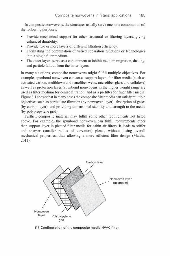
Composite nonwovens in fi lters: applications 165
In composite nonwovens, the structures usually serve one, or a combination of, the following purposes:
• Provide mechanical support for other structural or fi ltering layers, giving enhanced durability.
• Provide two or more layers of different fi ltration effi ciency. • Facilitating the combination of varied separation functions or technologies
into a single fi lter medium. • The outer layers serve as a containment to inhibit medium migration, dusting,
and particle fallout from the inner layers.
In many situations, composite nonwovens might fulfi ll multiple objectives. For example, spunbond nonwoven can act as support layers for fi lter media (such as activated carbon, meltblown and nanofi ber webs, microfi ber glass and cellulose) as well as protection layer. Spunbond nonwovens in the higher weight range are used as fi lter medium for coarse fi ltration, and as a prefi lter for fi ner fi lter media. Figure 8.1 shows that in many cases the composite fi lter media can satisfy multiple objectives such as particulate fi ltration (by nonwoven layer), absorption of gases (by carbon layer), and providing dimensional stability and strength to the media (by polypropylene grid).
Further, composite material may fulfi ll some other requirements not listed above. For example, the spunbond nonwoven can fulfi ll requirements other than support layer in pleated fi lter media for cabin air fi lters. It leads to stiffer and sharper (smaller radius of curvature) pleats, without losing overall mechanical properties, thus allowing a more effi cient fi lter design (Maltha, 2011).
8.1 Confi guration of the composite media HVAC fi lter.
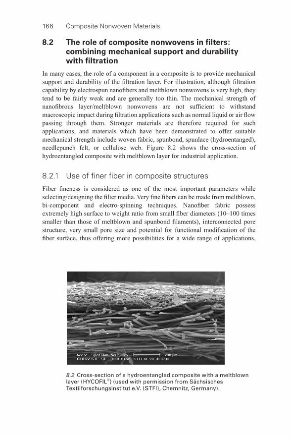
166 Composite Nonwoven Materials
8.2 The role of composite nonwovens in fi lters:
combining mechanical support and durability
with fi ltration
In many cases, the role of a component in a composite is to provide mechanical support and durability of the fi ltration layer. For illustration, although fi ltration capability by electrospun nanofi bers and meltblown nonwovens is very high, they tend to be fairly weak and are generally too thin. The mechanical strength of nanofi brous layer/meltblown nonwovens are not suffi cient to withstand macroscopic impact during fi ltration applications such as normal liquid or air fl ow passing through them. Stronger materials are therefore required for such applications, and materials which have been demonstrated to offer suitable mechanical strength include woven fabric, spunbond, spunlace (hydroentanged), needlepunch felt, or cellulose web. Figure 8.2 shows the cross- section of hydroentangled composite with meltblown layer for industrial application.
8.2.1 Use of fi ner fi ber in composite structures
Fiber fi neness is considered as one of the most important parameters while selecting/designing the fi lter media. Very fi ne fi bers can be made from meltblown, bi- component and electro- spinning techniques. Nanofi ber fabric possess extremely high surface to weight ratio from small fi ber diameters (10–100 times smaller than those of meltblown and spunbond fi laments), interconnected pore structure, very small pore size and potential for functional modifi cation of the fi ber surface, thus offering more possibilities for a wide range of applications,
8.2 Cross- section of a hydroentangled composite with a meltblown layer (HYCOFIL®) (used with permission from Sächsisches Textilforschungsinstitut e.V. (STFI), Chemnitz, Germany).
Composite nonwovens in fi lters: applications 167
ranging from air cleaning for automotive to environment conditioning or liquid fi ltration (Yoon et al. , 2006; Barhate and Ramakrishna, 2007; Dotti et al. , 2007). In all these applications, fi ner fi ber materials need to be supported by a stronger component in composite. There is another perspective of the use of thin layers of fi ner fi bers. The media made out of fi ner fi ber lead to higher fi ltration effi ciency at the cost of higher pressure differential across the fabric. For a suitable balance between effi ciency and levels of pressure, use of a thin layer of fi ner fi ber component in a composite is required.
The fi ner fi ber layer can be positioned upstream before the macro fi ltration substrate to enhance surface fi ltration performance or downstream of the macro fi ltration substrate to improve depth fi ltration in order to capture particles within the body of the media. Finer media at the upstream side of surface fi lters lead to better cake dislodgement and prevention of particle penetration inside fi lter media (Kothari et al. , 1993; Ciach and Gradon, 1998; Callé et al. , 2002), which in turn results in better long term performance of fi lter media. However, a thin layer of nanofi bers on meltblown media has a weak bond and higher production costs (Lydall Filtration and Separation, 2013). The weak bond is a problem in the nanofi ber layer in self- cleaning or pulse cleaning fi lter applications. The dust cake formed on the upstream side of the fi lter media can be removed by back- pulsing air through the media to rejuvenate it. As a great force is exerted on the surface during the back- pulse, nanofi bers with poor adhesion to substrates, or comprised of delicate nanofi bers, can delaminate when the shock wave moves from the interior of the fi lter through the substrate to the nanofi ber. However, the new nanofi ber technology was reported to provide excellent adhesion to the substrate, enabling longer life and improved effi ciencies in pulse- cleaning applications because of greater particle collection and overall energy expended during the cleaning process. The plurality of nanofi ber layers also provides superior durability (Wertz and Schneiders, 2009).
Studies have demonstrated that high effi ciency composite fi lters made up of nano- and microfi bers, when added to industrial gas fi ltration systems (such as dust- collecting pulse- clean cartridges) extend fi lter life (Kosminder and Scott, 2002). Researchers have also developed an industrial gas fi lter medium consisting of 70% polymers with a regular melting temperature and 30% polymers with a low melting temperature. This medium employs polyester felts as the base material for the polymer mix, with a prepared polyamide nano- sized web at the upstream side of the fabric (Yeo et al. , 2007). A thermal roller was employed to bond the overlapped fi lter medium. Subsequent work to evaluate fi ltration capability revealed greater collection effi ciency and more stable fi ltration behavior in the medium with the nano- sized web showing more stable fi ltration behavior and improved collection effi ciency. The levels of dust found to be left in fabric containing nanofi ber web was also revealed to be far lower than those in fabric with no nanofi ber web (Yeo et al. , 2007). One patent disclosure suggested that high fi ltration effi ciency could be achieved by enhancing the upstream surface of
168 Composite Nonwoven Materials
a spunbonded medium via use of a micro- or nanofi ber structure on the upstream surface (Chung et al. , 2008).
Most often the combination of structure is made by heat bonding the process either by purely heating the process or by using hot melt adhesive. Combination is also possible by ultrasonic welding. Hydro- entanglement and needlepunching are also interesting options for the joining together of two layers to produce composite fi ltration materials. In one study, the needlepunching technique was used as the initial step in preparing P84 needlefelt. P84 needlefelt was then prepared by taking the upstream side of felt, constructed of standard 2.2 dtexfi ber, and adding 1.0 dtexmicrofi ber. This produces a medium capable of increasing gas fi ltration effi ciency by preventing deep dust penetration, maintaining stable pressure drop, and facilitating good bag life. As well as being an effective fi ltration medium in gas fi ltration systems, P84 fi bers can additionally be used as either a PTFE (polytetrafl uoroethylene) fi ber blending partner, or in the construction of surface layers on homopolymer acrylic, polyester or m -aramide felts (Connor, 1997). Varied combinations of medium have been tested in layered construction, leading to the formation of such composites as a felt- like layered construction of PTFE and glass paper (Fagan, 1982).
In the case of depth fi ltration, use of nanofi ber was also reported. Finer media trap tiny particles of the order of <0.5 mm at the fi nal stage and therefore it is possible to achieve HEPA (high effi ciency particulate air) grade regarding collection effi ciency (Kattamuri et al. , 2005; Ahn et al. , 2006; Podgorski et al. , 2006; Yun et al. , 2007; Wang et al. , 2008a, 2008b). Problems of structural damage and delamination in depth fi ltration applications can be largely overcome by suitable composite development. In the combination of meltblown (M) and spunlaid (S) nonwovens (SMS, SMMS or SSMMS), the spunlaid component provides the required strength and abrasion properties and the meltblown component act as a barrier for liquids or particles. For the aforesaid reason, a major portion of meltblown material is used in composite form (Hutten, 2007). Figure 8.3 shows the cross- sectional view of an SMS fabric.
In a nanofi ber composite, fi lter media were made where lighter layers of nanofi bers were applied to the spunbond materials, then two layers of spunbond/nanofi ber composite were laminated together in a face- to-face confi guration, i.e. a structure of spunbond- nanofi ber-lamination- nanofi ber-spunbond.
The outer layers protect the nanofi ber layer from abrasion and other mechanical damage, and therefore would also prevent the nanofi ber layer from scuffi ng (Graham et al. , 2003). The material can be used for depth fi ltration situations in non- cleanable fi lters. A triple layer design of fi brous fi lters was reported (Podgorski et al. , 2006) wherein the middle nanofi brous layer was placed between the back support layer of densely packed microfi bers and the front porous layer of fi bers of a few micrometer diameter. The composite was found to be useful to remove the nanoparticles along with other polydispersed aerosol particles.
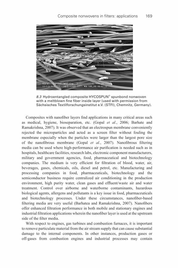
Composite nonwovens in fi lters: applications 169
Composites with nanofi ber layers fi nd applications in many critical areas such as medical, hygiene, bioseparation, etc. (Gopal et al. , 2006; Barhate and Ramakrishna, 2007). It was observed that an electrospun membrane conveniently rejected the microparticles and acted as a screen fi lter without fouling the membrane especially when the particles were larger than the largest pore size of the nanofi brous membrane (Gopal et al. , 2007). Nanofi brous fi ltering media can be used where high- performance air purifi cation is needed such as in hospitals, healthcare facilities, research labs, electronic component manufacturers, military and government agencies, food, pharmaceutical and biotechnology companies. The medium is very effi cient for fi ltration of blood, water, air, beverages, gases, chemicals, oils, diesel and petrol, etc. Manufacturing and processing companies in food, pharmaceuticals, biotechnology and the semiconductor business require centralized air conditioning in the production environment, high purity water, clean gases and effl uent/waste air and water treatment. Control over airborne and waterborne contaminants, hazardous biological agents, allergens and pollutants is a key issue in food, pharmaceuticals and biotechnology processes. Under these circumstances, nanofi ber- based fi ltering media are very useful (Barhatea and Ramakrishna, 2007). Nanofi bers offer enhanced fi ltration performance in both mobile and stationary engines and industrial fi ltration applications wherein the nanofi ber layer is used at the upstream side of the fi lter media.
With respect to engines, gas turbines and combustion furnaces, it is important to remove particulate material from the air stream supply that can cause substantial damage to the internal components. In other instances, production gases or off- gases from combustion engines and industrial processes may contain
8.3 Hydroentangled composite HYCOSPUN® spunbond nonwoven with a meltblown fi ne fi ber inside layer (used with permission from Sächsisches Textilforschungsinstitut e.V. (STFI), Chemnitz, Germany).
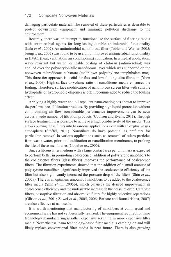
170 Composite Nonwoven Materials
damaging particulate material. The removal of these particulates is desirable to protect downstream equipment and minimize pollution discharge to the environment.
Recently, there was an attempt to functionalize the surface of fi ltering media with antimicrobial agents for long- lasting durable antimicrobial functionality (Lala et al. , 2007). An antimicrobial nanofi brous fi lter (Tobler and Warner, 2005; Jeong et al. , 2007) was found to be useful for improved antimicrobial functionality in HVAC (heat, ventilation, air conditioning) application. In a medial application, water resistant but water permeable coating of chitosan (antimicrobial) was applied over the polyacrylonitrile nanofi brous layer which was supported on the nonwoven microfi brous substrate (meltblown polyethylene terephthalate mat). This three- tier approach is useful for fl ux and low fouling ultra fi ltration (Yoon et al. , 2006). High surface- to-volume ratio of nanofi brous media enhances the fouling. Therefore, surface modifi cation of nanofi brous screen fi lter with suitable hydrophilic or hydrophobic oligomer is often recommended to reduce the fouling effect.
Applying a highly water and oil repellent nano- coating has shown to improve the performance of fi ltration products. By providing high liquid protection without compromising air fl ow, considerable performance improvements can be seen across a wide number of fi ltration products (Coulson and Evans, 2011). Through surface treatment, it is possible to achieve a high conductivity of the media. This allows putting these fi lters into hazardous applications even with an explosive gas atmosphere (Stoffel, 2011). Nanofi bers do have potential as prefi lters for particulate removal in various applications such as removal of micro- particles from waste- water, prior to ultrafi ltration or nanofi ltration membranes, to prolong the life of these membranes (Gopal et al. , 2006).
Since a fi brous fi lter medium with a large contact area per unit mass is expected to perform better in promoting coalescence, addition of polystyrene nanofi bers to the coalescence fi lters (glass fi bers) improves the performance of coalescence fi lters. The fi ltration experiments showed that the addition of a small amount of polystyrene nanofi bers signifi cantly improved the coalescence effi ciency of the fi lter but also signifi cantly increased the pressure drop of the fi lters (Shin et al. , 2005a). There is an optimum amount of nanofi bers to be added to the coalescence fi lter media (Shin et al. , 2005b), which balances the desired improvement in coalescence effi ciency and the undesirable increase in the pressure drop. Catalytic fi lters, adsorptive fi ltration and absorptive fi lters for highly selective separations (Gibson et al. , 2001; Zuwei et al. , 2005, 2006; Barhate and Ramakrishna, 2007) are also effective at nanoscale.
It is worth mentioning that manufacturing of nanofi bers at commercial and economical scale has not yet been fully realized. The equipment required for nano technology manufacturing is rather expensive resulting in more expensive fi lter media. Nevertheless, nano technology- based fi lter media is catching on and will likely replace conventional fi lter media in near future. There is also growing

Composite nonwovens in fi lters: applications 171
interest on bi- component fi bers, which have a higher number of island fi bers. With this island- in-the- sea formation, 1200 fi ne island fi bers can be produced. Apart from the island- in-the- sea technology, the segmented pie technology also helps in producing fi ne fi bers and has become more popular in recent years.
8.2.2 Use of scrim
In industrial pulse- jet fi ltration, scrim reinforced needlefelts are used for improving dimensional stability and greater durability. Figure 8.4 shows the sectional view of a hydroentangled composite nonwoven with scrim used for the industrial gas fi ltration process. Over the years, use of scrim becomes limited in gas fi ltration applications due to the improvement in the fi ber consolidation process. However, scrim composites are often benefi cial for high- temperature application. A range of scrim composite materials for high- temperature application are offered by EvonikFibres GmbH, such as polyimide (P84) fi brous batt with polytetrafl uoroethylene (PTFE) scrim, P84 fi ber nonwoven with P84 scrim, a fi brous blend of polyphylene sulfi de fi ber (PPS) and P84 with PPS scrim etc. Figure 8.5 shows the artistic view of P84 nonwoven with P84 scrim used for high- temperature application.
Research aimed at developing materials suitable for use in high- temperature applications has found that fi lter fabrics constructed from basalt- based composites produce some successful results (Johnson and Handy, 2003). The success of such materials lies in the fact that they combine the fi ltering characteristics of P84 with key properties of the basalt fabric used as scrim, including high chemical resistance, thermal resistance and strength. In scrim fabrics, if the nonwoven layer shrinks it does not cause any change in the dimension of fi lter bags, meaning there
8.4 Hydroentangled composite HYCOFIL® nonwoven with scrim (used with permission from Sächsisches Textilforschungsinstitut e.V. (STFI), Chemnitz, Germany).
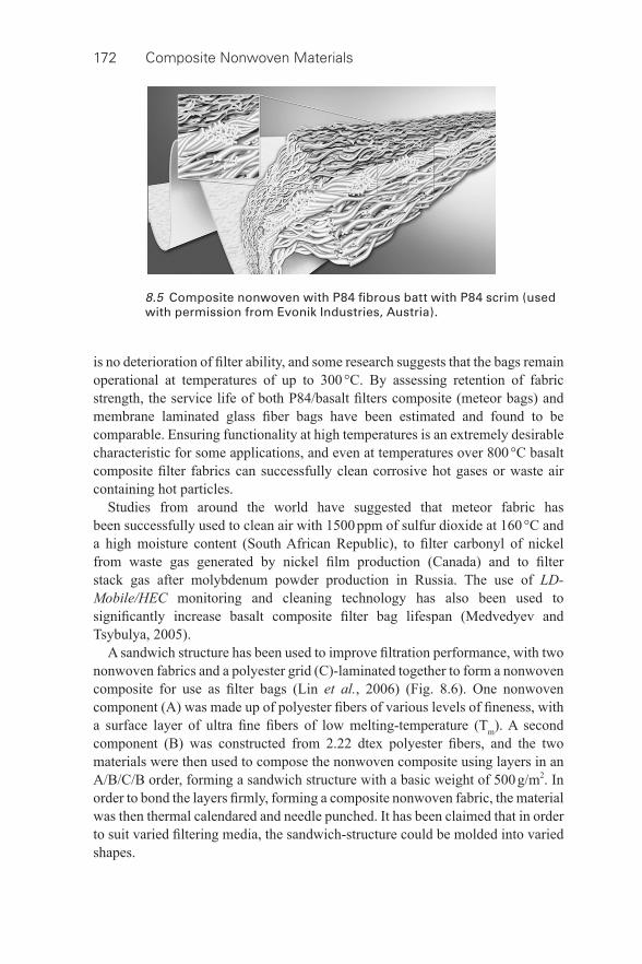
172 Composite Nonwoven Materials
is no deterioration of fi lter ability, and some research suggests that the bags remain operational at temperatures of up to 300 °C. By assessing retention of fabric strength, the service life of both P84/basalt fi lters composite (meteor bags) and membrane laminated glass fi ber bags have been estimated and found to be comparable. Ensuring functionality at high temperatures is an extremely desirable characteristic for some applications, and even at temperatures over 800 °C basalt composite fi lter fabrics can successfully clean corrosive hot gases or waste air containing hot particles.
Studies from around the world have suggested that meteor fabric has been successfully used to clean air with 1500 ppm of sulfur dioxide at 160 °C and a high moisture content (South African Republic), to fi lter carbonyl of nickel from waste gas generated by nickel fi lm production (Canada) and to fi lter stack gas after molybdenum powder production in Russia. The use of LD-Mobile/HEC monitoring and cleaning technology has also been used to signifi cantly increase basalt composite fi lter bag lifespan (Medvedyev and Tsybulya, 2005).
A sandwich structure has been used to improve fi ltration performance, with two nonwoven fabrics and a polyester grid (C)-laminated together to form a nonwoven composite for use as fi lter bags (Lin et al. , 2006) ( Fig. 8.6 ). One nonwoven component (A) was made up of polyester fi bers of various levels of fi neness, with a surface layer of ultra fi ne fi bers of low melting- temperature (T m ). A second component (B) was constructed from 2.22 dtex polyester fi bers, and the two materials were then used to compose the nonwoven composite using layers in an A/B/C/B order, forming a sandwich structure with a basic weight of 500 g/m 2 . In order to bond the layers fi rmly, forming a composite nonwoven fabric, the material was then thermal calendared and needle punched. It has been claimed that in order to suit varied fi ltering media, the sandwich- structure could be molded into varied shapes.
8.5 Composite nonwoven with P84 fi brous batt with P84 scrim (used with permission from Evonik Industries, Austria).
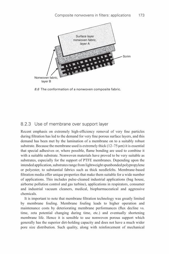
Composite nonwovens in fi lters: applications 173
8.2.3 Use of membrane over support layer
Recent emphasis on extremely high- effi ciency removal of very fi ne particles during fi ltration has led to the demand for very fi ne porous surface layers, and this demand has been met by the lamination of a membrane on to a suitably robust substrate. Because the membrane used is extremely thick (12–75 μ m) it is essential that special adhesives or, where possible, fl ame bonding are used to combine it with a suitable substrate. Nonwoven materials have proved to be very suitable as substrates, especially for the support of PTFE membranes. Depending upon the intended application, substrates range from lightweight spunbonded polypropylene or polyester, to substantial fabrics such as thick needlefelts. Membrane- based fi ltration media offer unique properties that make them suitable for a wide number of applications. This includes pulse- cleaned industrial applications (bag house, airborne pollution control and gas turbine), applications in respirators, consumer and industrial vacuum cleaners, medical, biopharmaceutical and aggressive chemicals.
It is important to note that membrane fi ltration technology was greatly limited by membrane fouling. Membrane fouling leads to higher operation and maintenance costs by deteriorating membrane performances (fl ux decline vs. time, zeta potential changing during time, etc.) and eventually shortening membrane life. Hence it is sensible to use nonwoven porous support which generally has the superior dirt- holding capacity and does not have a much wider pore size distribution. Such quality, along with reinforcement of mechanical
8.6 The conformation of a nonwoven composite fabric.
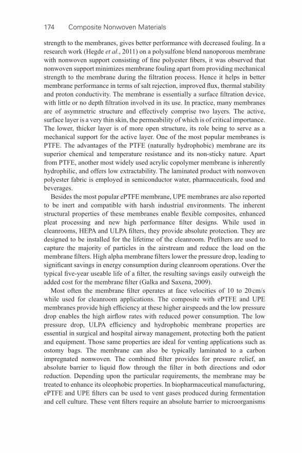
174 Composite Nonwoven Materials
strength to the membranes, gives better performance with decreased fouling. In a research work (Hegde et al. , 2011) on a polysulfone blend nanoporous membrane with nonwoven support consisting of fi ne polyester fi bers, it was observed that nonwoven support minimizes membrane fouling apart from providing mechanical strength to the membrane during the fi ltration process. Hence it helps in better membrane performance in terms of salt rejection, improved fl ux, thermal stability and proton conductivity. The membrane is essentially a surface fi ltration device, with little or no depth fi ltration involved in its use. In practice, many membranes are of asymmetric structure and effectively comprise two layers. The active, surface layer is a very thin skin, the permeability of which is of critical importance. The lower, thicker layer is of more open structure, its role being to serve as a mechanical support for the active layer. One of the most popular membranes is PTFE. The advantages of the PTFE (naturally hydrophobic) membrane are its superior chemical and temperature resistance and its non- sticky nature. Apart from PTFE, another most widely used acrylic copolymer membrane is inherently hydrophilic, and offers low extractability. The laminated product with nonwoven polyester fabric is employed in semiconductor water, pharmaceuticals, food and beverages.
Besides the most popular ePTFE membrane, UPE membranes are also reported to be inert and compatible with harsh industrial environments. The inherent structural properties of these membranes enable fl exible composites, enhanced pleat processing and new high performance fi lter designs. While used in cleanrooms, HEPA and ULPA fi lters, they provide absolute protection. They are designed to be installed for the lifetime of the cleanroom. Prefi lters are used to capture the majority of particles in the airstream and reduce the load on the membrane fi lters. High alpha membrane fi lters lower the pressure drop, leading to signifi cant savings in energy consumption during cleanroom operations. Over the typical fi ve- year useable life of a fi lter, the resulting savings easily outweigh the added cost for the membrane fi lter (Galka and Saxena, 2009).
Most often the membrane fi lter operates at face velocities of 10 to 20 cm/s while used for cleanroom applications. The composite with ePTFE and UPE membranes provide high effi ciency at these higher airspeeds and the low pressure drop enables the high airfl ow rates with reduced power consumption. The low pressure drop, ULPA effi ciency and hydrophobic membrane properties are essential in surgical and hospital airway management, protecting both the patient and equipment. Those same properties are ideal for venting applications such as ostomy bags. The membrane can also be typically laminated to a carbon impregnated nonwoven. The combined fi lter provides for pressure relief, an absolute barrier to liquid fl ow through the fi lter in both directions and odor reduction. Depending upon the particular requirements, the membrane may be treated to enhance its oleophobic properties. In biopharmaceutical manufacturing, ePTFE and UPE fi lters can be used to vent gases produced during fermentation and cell culture. These vent fi lters require an absolute barrier to microorganisms
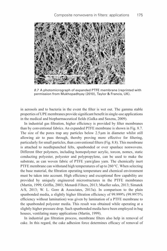
Composite nonwovens in fi lters: applications 175
in aerosols and to bacteria in the event the fi lter is wet out. The gamma stable properties of UPE membranes provide signifi cant benefi t in single- use applications in the medical and biopharmaceutical fi elds (Galka and Saxena, 2009).
In industrial gas fi ltration, higher effi ciency is provided by fi lter membranes than by conventional fabrics. An expanded PTFE membrane is shown in Fig. 8.7 . The size of the pores trap any particles below 2.5 μ m in diameter whilst still allowing air to pass through, thereby proving more effective for fi ltering, particularly for small particles, than conventional fi lters ( Fig. 8.8 ). This membrane is attached to needlepunched felts, spunbonded or over spunlace nonwovens. Different fi ber polymers, including homopolymer acrylic, torcon, nomex, static conducting polyester, polyester and polypropylene, can be used to make the substrate, as can woven fabric of PTFE yarn/glass yarn. The chemically inert PTFE membrane can withstand high temperatures of up to 260 °C. When selecting the base material, the fi ltration operating temperature and chemical environment must be taken into account. High effi ciency and exceptional fl ow capability are provided by uniquely engineered microstructures in the PTFE membranes (Martin, 1999; Griffi n, 2003; Menardi Filters, 2013; Mueller sales, 2013; Simatek A/S, 2013; W. L. Gore & Associates, 2013a). In comparison to the plain spunbonded media, a slightly higher fi ltration effi ciency of 99.999% (99.9975% effi ciency without lamination) was given by lamination of a PTFE membrane to the spunbonded polyester media. This result was obtained while operating at a slightly higher pressure drop. Such spunbonded media have been employed in bag houses, ventilating many applications (Martin, 1999).
In industrial gas fi ltration process, membrane fi lters also help in removal of cake. In this regard, the cake adhesion force determines effi cacy of removal of
8.7 A photomicrograph of expanded PTFE membrane (reprinted with permission from Mukhopadhyay (2010), Taylor & Francis, UK).
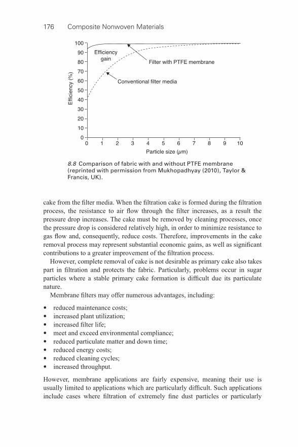
176 Composite Nonwoven Materials
cake from the fi lter media. When the fi ltration cake is formed during the fi ltration process, the resistance to air fl ow through the fi lter increases, as a result the pressure drop increases. The cake must be removed by cleaning processes, once the pressure drop is considered relatively high, in order to minimize resistance to gas fl ow and, consequently, reduce costs. Therefore, improvements in the cake removal process may represent substantial economic gains, as well as signifi cant contributions to a greater improvement of the fi ltration process.
However, complete removal of cake is not desirable as primary cake also takes part in fi ltration and protects the fabric. Particularly, problems occur in sugar particles where a stable primary cake formation is diffi cult due its particulate nature.
Membrane fi lters may offer numerous advantages, including:
• reduced maintenance costs; • increased plant utilization; • increased fi lter life; • meet and exceed environmental compliance; • reduced particulate matter and down time; • reduced energy costs; • reduced cleaning cycles; • increased throughput.
However, membrane applications are fairly expensive, meaning their use is usually limited to applications which are particularly diffi cult. Such applications include cases where fi ltration of extremely fi ne dust particles or particularly
8.8 Comparison of fabric with and without PTFE membrane (reprinted with permission from Mukhopadhyay (2010), Taylor & Francis, UK).
Composite nonwovens in fi lters: applications 177
hazardous contaminants is required, or where unique advantages (such as cake release) may be offered by interaction with a membrane surface. As an example, hybrid technology which combines electrostatic charges with fabric fi ltration offers improved effi ciency when utilizing membrane fabrics with lower air to cloth ratios, thanks to the substantial reduction in the burden of particulates on the fabric fi lter (Mukhopadhyay, 2009).
In a study by Fritsky (2013) based on particulate emissions at a municipal solid waste combustion facility, the performance of GORE-TEX® membrane (PTFE)/TEFLON® B fi berglass fabric fi lter bags was assessed. This technology is made up of two key elements: a pulse- jet fabric fi lter collector, which is additionally equipped with a lime slurry spray dryer absorber. Some factors attributable to the success of the fabric fi lter collector include: superior operation of the boiler and spray drier absorber; infrequent and low pressure pulsing; prevention of the penetration of particulate matter into and beyond the GORE-TEX membrane (wear of abrasive dust can otherwise cause fi berglass fi ber breakage); and excellent bag- to-cage fi t and bag design to minimize fl ex fatigue of fi berglass fi bers against cage wires, whilst allowing adequate bag movement for effi cient cleaning (Fritsky, 2013). It may be added that membrane- less glass fi ber fabrics are unable to meet current emission requirements.
However, fi ltration performance is degraded by premature membrane failure. Particularly during cleaning pulses, fi lter bags are subjected to continual stresses and fl exing which may lead to breaking of the membrane’s bond, causing fi brils structure and the development of cracks. Various factors, including the frequency of cleaning pulses and the amount of pulse pressure used, affect the severity and extent of this crack development. Pulse pressure and pulse- on-time during membrane fi lter use, should be kept below 550 kPa and 350 milliseconds, respectively (Hardman, 2000; Savage et al. , 2013; W. L. Gore & Associates, 2013b). Innovative development and re- engineering of PTFE membranes can achieve higher strength levels and increased air fl ow, whilst maintaining fi ltration effi ciency.
8.2.4 Coated fi lters
A coated fi lter can be considered as composite, as it consists of two different materials in a single structure. Sometimes the application of resin to a nonwoven fi lter medium is wrongly referred to as coating. The resin is applied as saturant (sometimes referred to as an impregnate). Unlike coating, which is intended to cover the surface of the substrate, a saturant is expected to penetrate the media and form bond points in the interior as well as at the surfaces. Because of the need for penetration, low viscosity is a very desirable properly in liquid resin systems for fi lter media.
It is a little more complex to coat needlefelt fabric surfaces, and it can occasionally be diffi cult to establish the difference between coated fabrics and
178 Composite Nonwoven Materials
bonded media. Water repellency is important to a fi lter medium, particularly air fi ltration media, because it helps to prevent it from being wetted out and damaged when exposed to water. Wetting of HEPA fi lter media leads to degradation of fi lter strength to a large extent and could reduce resistance to medium breach. Water repellency is incorporated into a fi lter medium by the use of hydrophobic material in the media surface. This can be done by the use of water repellent fi bers or by water repellent coatings. Polyester and polyolefi n are examples of fi bers that are hydrophobic in nature and will impart water repellency to a fi lter medium. Waxes, silicones, and fl uorocarbon resins are examples of water repellent coatings that can be applied to fi lter media. Some binders such as styrene acrylates also impart a degree of water repellency (Hutten, 2007). There are various methods for coating fi lter media, including surface coating, steeping, foam coating and coating with inert powders.
Surface coating
To achieve fi ner particle fi ltration and improve cake discharge during the industrial gas fi ltration process, microporous polymer coatings can be applied to the face of nonwoven fabrics. In addition to improving fi ltration effi ciency and cake release, this process improves the effi ciency of heat, chemical and abrasion resistance (Goosens, 1993). When applied to the needlefelt surface, coatings form a quasi- membrane structure. The addition of a Tefl on B coating on the surface of glass fi ber fabric for boiler applications is common (Carr and Smith, 1984). During the late 1980s Ravensworth Ltd developed a range of coated materials, under the trade name of Ravlex, for achieving superior fi ltration performance. Three main product groups are generally used for the coating process: Ravlex MX, Ravlex PPC and Ravlex YP. Ravlex MX is a PTFE microporous embedded coating which is applied to the carrier needlefelt fi ltration surface. Ravlex MX is generally used for the fi ltration of fi ne particles in the chemical, pharmaceutical and food industries. Formulated from PTFE, the Ravlex PPC coating offers higher permeability than the Ravlex MX due to its larger pore size, thereby making it suitable for the fi ltering agglomerating or sticky dusts. With a pore structure similar to Ravlex PPC, Ravlex YP is formulated from polyurethane (PU), whilst another recent product, Ravlex CR, is formulated from PTFE coating. As previously outlined, all such coatings usually offer such benefi ts as high abrasion resistance, effective cake release, increased air permeability, reduced operational pressure drop (resistance to blinding), reduced cleaning frequency and extended fi lter operational life (Gibbons, 2002; Lydon, 2004; Ravensworth Ltd, 2004a, 2004b).
MicroWeb 2000 and MicroWeb II media, which comprise polytetrafl uoro-ethylene (PTFE) and acrylic coatings, respectively, on a polyester needlefelt, have been introduced by Webron and are designed to provide reasonably high permeability. Similarly, a number of treatment processes are produced by
Composite nonwovens in fi lters: applications 179
Fratelli Testori. These include Novates , which is a coating of polyurethane (PU) on polyester or acrylic felts to provide hydrophobic and oleophobic character-istics; and Mantes , which gives enhanced chemical resistance via application of a resin chemical treatment containing PTFE to acrylics and high- temperature fi bers. Tuf- tex™ thermosetting resins have been developed by Madison Filter for the coating of polypropylene, polyamide and polyester substrates. Once sprayed or knifed onto the surface of the fi lter fabric, these provide good abrasion resistance and enhanced dimensional stability (Lydon, 2004).
Steeping
During application, fabric is steeped in a chemical solution containing high concentrations of PTFE and fl uoride resins. The fl uorides are then fi xed on the fi bers by drying and heating the fabric. Application of this process to polyester or acrylic fi ber fabrics enhances both cake release properties and protection from chemical activity (Hardman, 2000). When treating glass fi ber fabric, the fabric is immersed in an emulsion of water, silicon, silicon graphite or colloidal graphite or fl uorocarbon compounds, before excess liquid is removed by squeezing the material through a roller, and the fabric is then dried (Ray, 2004).
Foam coating (Goosens, 1993)
Aqueous- based acrylic latex is usually the principle ingredient of the treatment. In order to ensure that a fi ne, regular, stable pore structure is formed and that any specifi cally required characteristics (such as antistatic or hydrophobic properties) are produced, a range of chemical agents may constitute the precise formulation. Surface chemistry factors are the key factors governing the selection of polymer for coating, and the fi nal product must feature effective chemical affi nity between the contiguous materials involved. Figure 8.9 shows a foam layer electron photomicrograph.
Using this approach in the production of acrylic foam- coated needlefelts produces such materials with the capability of operating continuously at temperatures up to approximately 120 °C. These materials are not, however, usually resistant to hydrolytic conditions, which can potentially lead to structural collapse and premature pressurization. The specifi c density of the foam when applied to the material is also essential for successful application. If the density is too high, the substrate is wetted excessively. This leads to inadequate penetration and poor mechanical bonding as a result of the unacceptable air permeability and too low a density, increasing the risk of delamination.
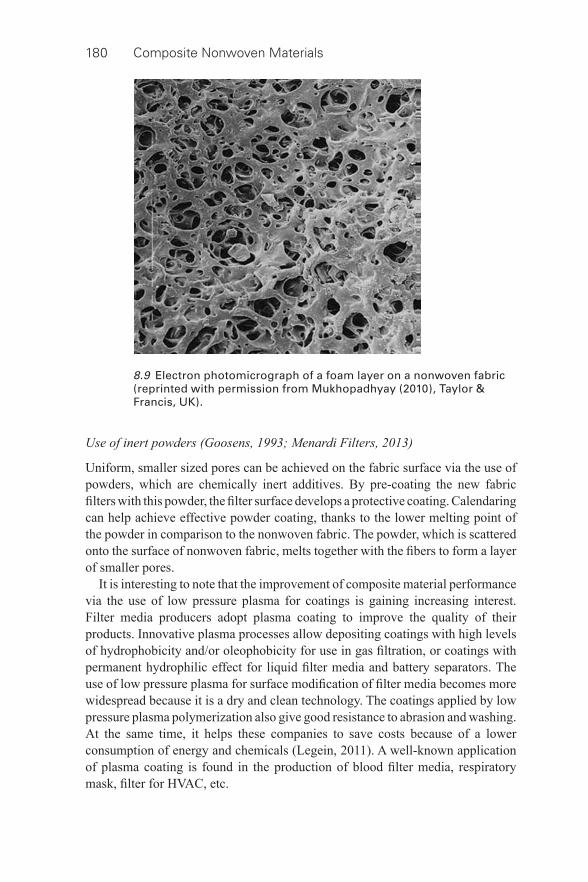
180 Composite Nonwoven Materials
Use of inert powders (Goosens, 1993; Menardi Filters, 2013)
Uniform, smaller sized pores can be achieved on the fabric surface via the use of powders, which are chemically inert additives. By pre- coating the new fabric fi lters with this powder, the fi lter surface develops a protective coating. Calendaring can help achieve effective powder coating, thanks to the lower melting point of the powder in comparison to the nonwoven fabric. The powder, which is scattered onto the surface of nonwoven fabric, melts together with the fi bers to form a layer of smaller pores.
It is interesting to note that the improvement of composite material performance via the use of low pressure plasma for coatings is gaining increasing interest. Filter media producers adopt plasma coating to improve the quality of their products. Innovative plasma processes allow depositing coatings with high levels of hydrophobicity and/or oleophobicity for use in gas fi ltration, or coatings with permanent hydrophilic effect for liquid fi lter media and battery separators. The use of low pressure plasma for surface modifi cation of fi lter media becomes more widespread because it is a dry and clean technology. The coatings applied by low pressure plasma polymerization also give good resistance to abrasion and washing. At the same time, it helps these companies to save costs because of a lower consumption of energy and chemicals (Legein, 2011). A well- known application of plasma coating is found in the production of blood fi lter media, respiratory mask, fi lter for HVAC, etc.
8.9 Electron photomicrograph of a foam layer on a nonwoven fabric (reprinted with permission from Mukhopadhyay (2010), Taylor & Francis, UK).
Composite nonwovens in fi lters: applications 181
8.3 The role of composite nonwovens in fi lters:
providing two or more layers of different
fi ltration effi ciency
In this case, composite nonwoven fi lter layers may be used in one of two forms: an upstreamlayer may be used as a prefi lter for the fi nal fi ltration layer, or, alternatively, gradient density depth fi ltration may be provided by arranging composite nonwoven layers of increasing densities. The outer layers can also serve as a containment to inhibit medium migration, dusting, and particle fallout from the inner layers. It may be added that process air from machining operations can have high concentrations of liquid aerosols, up to 100 mg/m 3 , and can cause several types of serious health effects on workers. A good drainage capacity is a vital requirement in a multistage fi ltration system.
The SMS fabric as referred to earlier (Section 8.2.1) works under the aforesaid philosophy wherein the meltblown middle layer provides higher fi ltration performance as compared to spunbonded side layers. As the meltblown layer conducts the fi nal fi ltration, the spunbonded layer acts as a prefi lter. In the gradient density medium, the differing bulk of each layer provides an increasingly effi cient level of fi ltration; as the fl uid moves through these increasingly fi ne layers, smaller and smaller contaminant particles are removed. Better fi ltration has been found through producing a unique gradient structure made in two steps. In the fi rst step, a pile stitch- bonded nonwoven with a one loop surface is manufactured. In the second step, the one loop surface of pile stitch- bonded nonwoven is compressed by putting a hydroentangled nonwoven on it (Smithies and Zimmerman, 2005; Lin et al. , 2006). The result is a gradient density medium and a photomicrograph of the structure is shown in Fig. 8.10 . The product is unique in that the fi bers of the upper pile surface are oriented in the direction of fl ow. This is in contrast to the conventional fi lter media where the fi bers are generally perpendicular to the direction of fl ow. The share in pile ranges from 98% to 99% and the number and size of cavities between the fi bers depend on the fi neness of fi bers used and the fabric thickness. The product is found to be useful for depth fi ltration applications.
In another development, wet lay technology can be used to create pore gradient in the media for the manufacture of air fi ltration media for many different applications, including HVAC, heavy duty air intake, automotive air intake, gas turbine and cabin air. Due to the gradient pore size, these media have a high dust- holding capacity and low pressure drop. The multilayer construction can combine mechanical fi ltration (a prefi lter that removes most particles), electrostatic fi ltration (the middle layer allows high initial fi ltration effi ciency) and the last layer/fi lter that allows high effi ciency for all fi lter life. The triple- layer construction makes it possible to create different kinds of products by simply modifying the grammage or the fi ber composition of the layers. The composite can be pleatable on different kinds of pleating machines. It is also possible to mix different fi bers (a wide range of natural, mineral, synthetic and man- made fi bers of varying
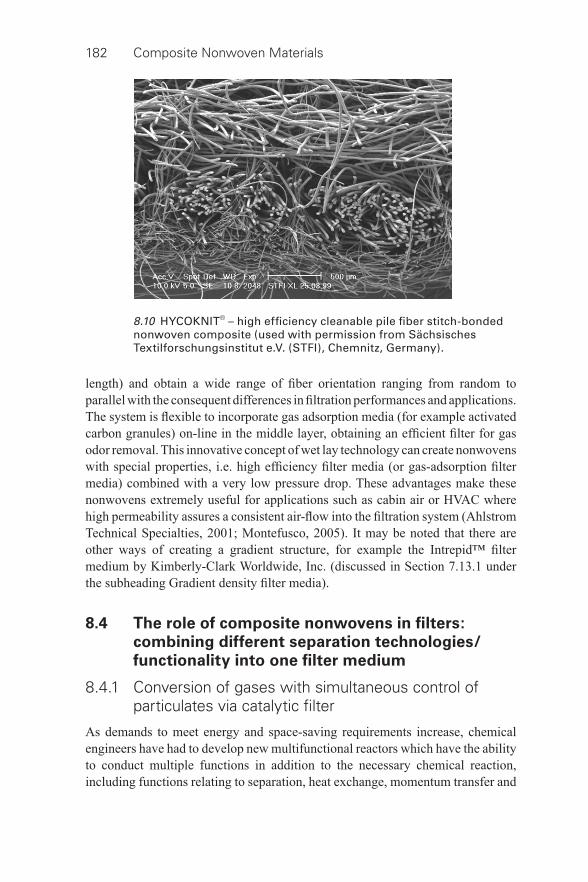
182 Composite Nonwoven Materials
length) and obtain a wide range of fi ber orientation ranging from random to parallel with the consequent differences in fi ltration performances and applications. The system is fl exible to incorporate gas adsorption media (for example activated carbon granules) on- line in the middle layer, obtaining an effi cient fi lter for gas odor removal. This innovative concept of wet lay technology can create nonwovens with special properties, i.e. high effi ciency fi lter media (or gas- adsorption fi lter media) combined with a very low pressure drop. These advantages make these nonwovens extremely useful for applications such as cabin air or HVAC where high permeability assures a consistent air- fl ow into the fi ltration system (Ahlstrom Technical Specialties, 2001; Montefusco, 2005). It may be noted that there are other ways of creating a gradient structure, for example the Intrepid™ fi lter medium by Kimberly-Clark Worldwide, Inc. (discussed in Section 7.13.1 under the subheading Gradient density fi lter media).
8.4 The role of composite nonwovens in fi lters:
combining different separation technologies/
functionality into one fi lter medium
8.4.1 Conversion of gases with simultaneous control of particulates via catalytic fi lter
As demands to meet energy and space- saving requirements increase, chemical engineers have had to develop new multifunctional reactors which have the ability to conduct multiple functions in addition to the necessary chemical reaction, including functions relating to separation, heat exchange, momentum transfer and
8.10 HYCOKNIT® – high effi ciency cleanable pile fi ber stitch- bonded nonwoven composite (used with permission from Sächsisches Textilforschungsinstitut e.V. (STFI), Chemnitz, Germany).
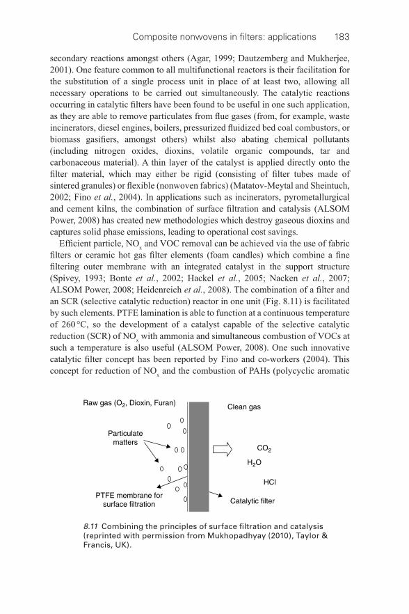
Composite nonwovens in fi lters: applications 183
secondary reactions amongst others (Agar, 1999; Dautzemberg and Mukherjee, 2001). One feature common to all multifunctional reactors is their facilitation for the substitution of a single process unit in place of at least two, allowing all necessary operations to be carried out simultaneously. The catalytic reactions occurring in catalytic fi lters have been found to be useful in one such application, as they are able to remove particulates from fl ue gases (from, for example, waste incinerators, diesel engines, boilers, pressurized fl uidized bed coal combustors, or biomass gasifi ers, amongst others) whilst also abating chemical pollutants (including nitrogen oxides, dioxins, volatile organic compounds, tar and carbonaceous material). A thin layer of the catalyst is applied directly onto the fi lter material, which may either be rigid (consisting of fi lter tubes made of sintered granules) or fl exible (nonwoven fabrics) (Matatov-Meytal and Sheintuch, 2002; Fino et al. , 2004). In applications such as incinerators, pyrometallurgical and cement kilns, the combination of surface fi ltration and catalysis (ALSOM Power, 2008) has created new methodologies which destroy gaseous dioxins and captures solid phase emissions, leading to operational cost savings.
Effi cient particle, NO x and VOC removal can be achieved via the use of fabric fi lters or ceramic hot gas fi lter elements (foam candles) which combine a fi ne fi ltering outer membrane with an integrated catalyst in the support structure (Spivey, 1993; Bonte et al. , 2002; Hackel et al. , 2005; Nacken et al. , 2007; ALSOM Power, 2008; Heidenreich et al. , 2008). The combination of a fi lter and an SCR (selective catalytic reduction) reactor in one unit ( Fig. 8.11 ) is facilitated by such elements. PTFE lamination is able to function at a continuous temperature of 260 °C, so the development of a catalyst capable of the selective catalytic reduction (SCR) of NO x with ammonia and simultaneous combustion of VOCs at such a temperature is also useful (ALSOM Power, 2008). One such innovative catalytic fi lter concept has been reported by Fino and co- workers (2004). This concept for reduction of NO x and the combustion of PAHs (polycyclic aromatic
8.11 Combining the principles of surface fi ltration and catalysis (reprinted with permission from Mukhopadhyay (2010), Taylor & Francis, UK).
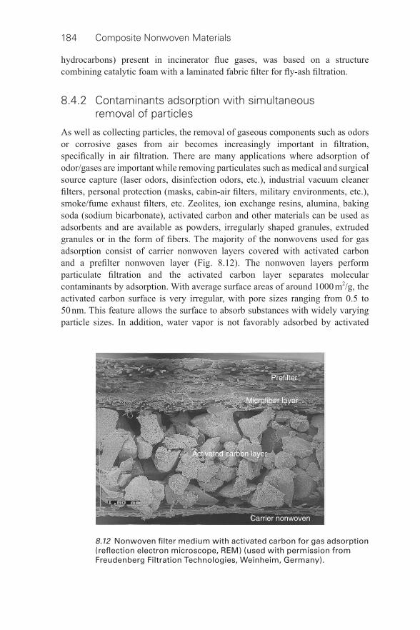
184 Composite Nonwoven Materials
hydrocarbons) present in incinerator fl ue gases, was based on a structure combining catalytic foam with a laminated fabric fi lter for fl y- ash fi ltration.
8.4.2 Contaminants adsorption with simultaneous removal of particles
As well as collecting particles, the removal of gaseous components such as odors or corrosive gases from air becomes increasingly important in fi ltration, specifi cally in air fi ltration. There are many applications where adsorption of odor/gases are important while removing particulates such as medical and surgical source capture (laser odors, disinfection odors, etc.), industrial vacuum cleaner fi lters, personal protection (masks, cabin- air fi lters, military environments, etc.), smoke/fume exhaust fi lters, etc. Zeolites, ion exchange resins, alumina, baking soda (sodium bicarbonate), activated carbon and other materials can be used as adsorbents and are available as powders, irregularly shaped granules, extruded granules or in the form of fi bers. The majority of the nonwovens used for gas adsorption consist of carrier nonwoven layers covered with activated carbon and a prefi lter nonwoven layer ( Fig. 8.12 ). The nonwoven layers perform particulate fi ltration and the activated carbon layer separates molecular contaminants by adsorption. With average surface areas of around 1000 m 2 /g, the activated carbon surface is very irregular, with pore sizes ranging from 0.5 to 50 nm. This feature allows the surface to absorb substances with widely varying particle sizes. In addition, water vapor is not favorably adsorbed by activated
8.12 Nonwoven fi lter medium with activated carbon for gas adsorption (refl ection electron microscope, REM) (used with permission from Freudenberg Filtration Technologies, Weinheim, Germany).
Composite nonwovens in fi lters: applications 185
carbon, as activated carbon is nonpolar. Due to this the surface can capture organic vapors at relatively high humidity. In addition, carbons with smaller pore sizes facilitate the increased capture of high- volatility vapors, due to having a greater affi nity for them.
A variety of different technologies exist to adjoin activated carbon powder or granules with the nonwoven fi lter medium. This could be printing, impregnation, applying a chemical binder or thermal bonding resin or spraying fi ne hot- melt fi bers. All technologies have common aims, to keep the surface of the activated carbon as free as possible to enhance the adsorption mechanism and to maximize the loading capacity for gaseous components or odors ( Fig. 8.13 ) (Sievert, 2011). In a study, sorbent particles (active carbon, aluminium oxide, chitosan, etc.) are caught by microfi bers in meltblown nonwovens. These nonwovens do not contain any additional agent to bind sorbent particles, hence the durability of binding sorbent particles is the key issue in this technology. Organoleptic assessment is useful to determine the durability of active carbon particle bonds in the composite nonwovens. The assessment of one part of a fi ltration face mask made out of composite nonwovens with active carbon showed that sorbent particles had a tendency to drop off (Nowicka, 2003).
Adsorbent media are increasingly being used for the removal of unpleasant odors and emission fumes in automotive cabin air fi lters, with great success. Absorbent media are also frequently employed in the removal of toxic and obnoxious chemicals from air in applications such as respirators and gas masks. Active carbon and similar adsorbents are used to combat the toxic effects of chemical agents in military affairs, to protect both military personnel and civilians. Liquid and soluble contaminants are also removed from fl uid streams by fi lter media containing adsorbents, via surface adsorption, i.e. the medium surface attracts the contaminants and the physical chemical effects hold them.
Filter media are used in liquid fi ltration for the removal of unpleasant- tasting contaminants and hydrocarbons from drinking water. In home water fi lters, activated carbon fi lter papers (a form of wet laid medium) are used extensively to remove undesirable taste and odor contaminants. Adsorbents have become a key element of HVAC (heat, ventilation, air conditioning) systems in both the home and workplace in recent years. As activated carbon is extremely effi cient at adsorbing most organic chemicals, it is unsurprising that it has become the most regularly used sorbent in HVAC systems. Figure 8.14 shows the fi lter with activated carbon for HVAC application. The fi lter (Austin air fi lter) is composed of a prefi lter (to trap larger particles such as dirt, lint and hair), a layer with a carbon and zeolite mix (to adsorb odors and gases), and HEPA fi lter paper (to remove harmful airborne particles).
One of the commercial grade nonwoven composites, known as PLEKX®, contains active ingredients greater than 82% of the media by weight to maximize adsorption and performance. A carbon layer is sandwiched between two nonwoven
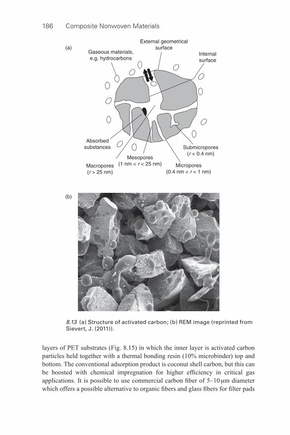
186 Composite Nonwoven Materials
8.13 (a) Structure of activated carbon; (b) REM image (reprinted from Sievert, J. (2011)).
layers of PET substrates ( Fig. 8.15 ) in which the inner layer is activated carbon particles held together with a thermal bonding resin (10% microbinder) top and bottom. The conventional adsorption product is coconut shell carbon, but this can be boosted with chemical impregnation for higher effi ciency in critical gas applications. It is possible to use commercial carbon fi ber of 5–10 μ m diameter which offers a possible alternative to organic fi bers and glass fi bers for fi lter pads
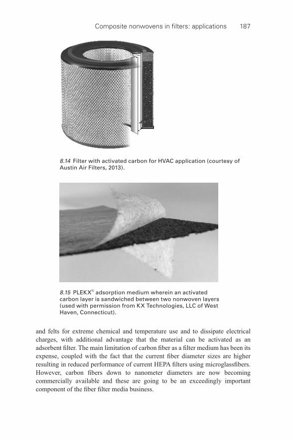
Composite nonwovens in fi lters: applications 187
and felts for extreme chemical and temperature use and to dissipate electrical charges, with additional advantage that the material can be activated as an adsorbent fi lter. The main limitation of carbon fi ber as a fi lter medium has been its expense, coupled with the fact that the current fi ber diameter sizes are higher resulting in reduced performance of current HEPA fi lters using microglassfi bers. However, carbon fi bers down to nanometer diameters are now becoming commercially available and these are going to be an exceedingly important component of the fi ber fi lter media business.
8.14 Filter with activated carbon for HVAC application (courtesy of Austin Air Filters, 2013).
8.15 PLEKX® adsorption medium wherein an activated carbon layer is sandwiched between two nonwoven layers (used with permission from KX Technologies, LLC of West Haven, Connecticut).
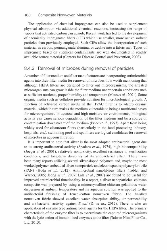
188 Composite Nonwoven Materials
The application of chemical impregnates can also be used to supplement physical adsorption via additional chemical reactions, increasing the range of vapors that activated carbon can adsorb. Recent work has led to the development of chemically impregnated fi bers (CIF) which use smaller, more active sorbent particles than previously employed. Such CIFs allow the incorporation of such material as carbon, permanganate/alumina, or zeolite into a fabric mat. Types of impregnate based on chemical contaminants are well documented in readily available source material (Centers for Disease Control and Prevention, 2003).
8.4.3 Removal of microbes during removal of particles
A number of fi lter medium and fi lter manufacturers are incorporating antimicrobial agents into their fi lter media for removal of microbes. It is worth mentioning that although HEPA fi lters are designed to fi lter out microorganisms, the arrested microorganisms can grow inside the fi lter medium under certain conditions such as suffi cient nutrients, proper humidity and temperature (Maus et al. , 2001). Some organic media such as cellulose provide nutrition for microbiological growth. A function of activated carbon media in the HVAC fi lter is to adsorb organic material, which in turn makes the medium vulnerable to being a nutritional haven for microorganisms. In aqueous and high moisture air environments, biological activity can cause serious degradation of the fi lter medium and be a source of contamination downstream of the medium (Price et al. , 1997). Apart from being widely used for cleanroom fi lters (particularly in the food processing industry, hospitals, etc.), swimming pool and spa fi lters are logical candidates for removal of microbes in aqueous fi ltration.
It is important to note that silver is the most adopted antibacterial agent due to its strong antibacterial activity (Spadaro et al. , 1974), high biocompatibility (Joeger et al. , 2001), relatively nontoxicity, excellent resistance to sterilization conditions, and long- term durability of its antibacterial effect. There have been many reports utilizing several silver- doped polymers and, maybe the most worked polymer embedded silver nanoparticle and electrospun is polyacrylonitrile (PAN) (Hoda et al. , 2012). Antimicrobial nanofi brous fi lters (Tobler and Warner, 2005; Jeong et al. , 2007; Lala et al. , 2007) are found to be useful for improved antimicrobial functionality. In a report, a silver nanoparticles–chitosan composite was prepared by using a microcrystalline chitosan gelatinous water dispersion at ambient temperature and its aqueous solution was applied to the antibacterial fi nishing of Tencel/cotton nonwoven fabric. The fi nished nonwoven fabric showed excellent water absorption ability, air permeability and antibacterial activity against E.coli (Di et al. , 2012). There is also an application of enzyme type antimicrobial agents for the HEPA fi lter. The primary characteristic of the enzyme fi lter is to exterminate the captured microorganisms with the lytic action of immobilized enzymes to the fi lter (Taiwan Nitta Filter Co., Ltd, 2013).
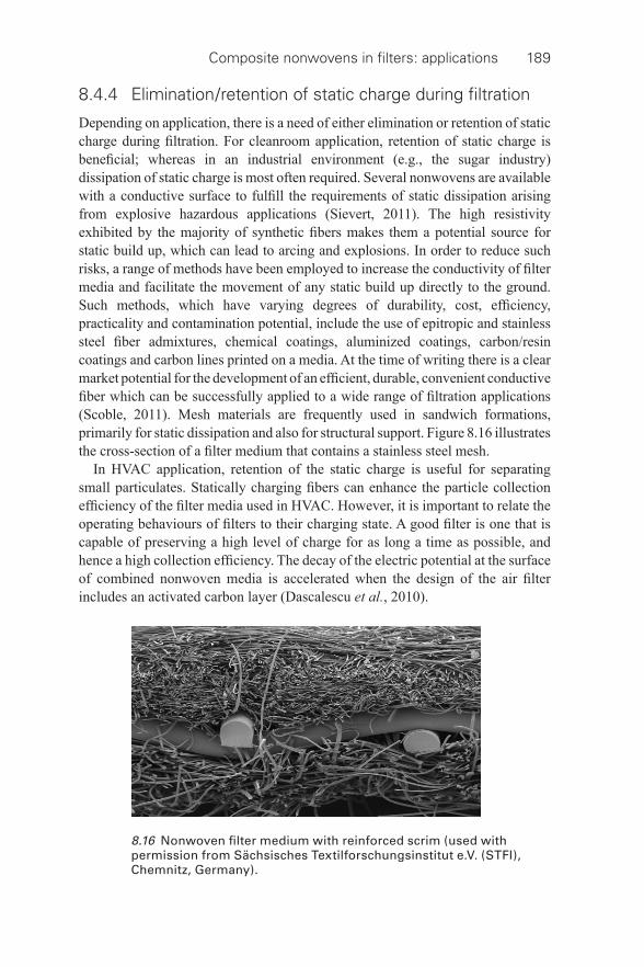
Composite nonwovens in fi lters: applications 189
8.4.4 Elimination/retention of static charge during fi ltration
Depending on application, there is a need of either elimination or retention of static charge during fi ltration. For cleanroom application, retention of static charge is benefi cial; whereas in an industrial environment (e.g., the sugar industry) dissipation of static charge is most often required. Several nonwovens are available with a conductive surface to fulfi ll the requirements of static dissipation arising from explosive hazardous applications (Sievert, 2011). The high resistivity exhibited by the majority of synthetic fi bers makes them a potential source for static build up, which can lead to arcing and explosions. In order to reduce such risks, a range of methods have been employed to increase the conductivity of fi lter media and facilitate the movement of any static build up directly to the ground. Such methods, which have varying degrees of durability, cost, effi ciency, practicality and contamination potential, include the use of epitropic and stainless steel fi ber admixtures, chemical coatings, aluminized coatings, carbon/resin coatings and carbon lines printed on a media. At the time of writing there is a clear market potential for the development of an effi cient, durable, convenient conductive fi ber which can be successfully applied to a wide range of fi ltration applications (Scoble, 2011). Mesh materials are frequently used in sandwich formations, primarily for static dissipation and also for structural support. Figure 8.16 illustrates the cross- section of a fi lter medium that contains a stainless steel mesh.
In HVAC application, retention of the static charge is useful for separating small particulates. Statically charging fi bers can enhance the particle collection effi ciency of the fi lter media used in HVAC. However, it is important to relate the operating behaviours of fi lters to their charging state. A good fi lter is one that is capable of preserving a high level of charge for as long a time as possible, and hence a high collection effi ciency. The decay of the electric potential at the surface of combined nonwoven media is accelerated when the design of the air fi lter includes an activated carbon layer (Dascalescu et al. , 2010).
8.16 Nonwoven fi lter medium with reinforced scrim (used with permission from Sächsisches Textilforschungsinstitut e.V. (STFI), Chemnitz, Germany).
190 Composite Nonwoven Materials
8.4.5 Removal of unwanted fl uid/vapor during removal of particulate contaminants
Nonwovens are often employed in absorbent structures in order to contain the absorbent material during particulate contaminant removal. However, because structures such as those in diapers, hygienic pads, and wipes do not involve an element of separation, they are not considered as fi lter media. Although hydrophobic, polyolefi ns, have an affi nity for oil. As such, they are frequently used to absorb oil from water, for example to control oil spills at sea. It should be noted that absorbency is often an undesired quality affecting a fi lter medium. Cellulose media has a tendency to absorb water, leading to softening and weakening of the fi lter structure and subsequently a reduced fi lter life. Furthermore, fi ltration performance may be inhibited by the fi ber swelling caused by moisture absorption.
Air- laid nonwoven structures, largely based on cellulose material, or short staple synthetic fi bers, including polyester, polypropylene, nylon or rayon along with super absorbent polymers (SAP), for example carboxy methyl cellulose (CMC), are frequently used for formation of composite structures. Within a composite, fi bers are inherently more effective because of their complementary structure. They also outperform super absorbent powders in handling (Dewsbury, 1990). If a considerable amount of long synthetic fi bers feature in the web produced, it can then be spunlaced (hydroentangled). The media can be effectively used for different application areas such as water removal from oils and fuels, air fi ltration, blood treatment fi lters and personal protective equipment.
In aviation fuel treatment, composite fi lter media consisting of super absorbent fi ber (SAF) has found wide acceptance. They are used in the form of monitor cartridges which incorporate multi- layer nonwoven composite. These cartridges are capable of reducing particulates to <0.3 mg/liter of solids in effl uent and reduce free and dispersed water to <5 ppm in effl uent. Cartridges are based either on outside to inside or inside to outside fuel fl ow and offer excellent fi ltration rate capability. The fl ow through the system is halted when hit with a localized slug of water because of super absorbent gel block. Presence of water/solids in the incoming fuel will give rise to an increase in pressure differential, or a decrease in the fl ow rate, as the cartridges reach their maximum capacity for solids, water or a combination of both (Dewsbury, 1990).
8.5 Applications of composite nonwovens
The usage of composite nonwoven fi lter media in fi ltration is very popular worldwide. They are being widely used in industrial air fi lter bags, industrial fume cartridge dust fi lters, residential ventilation panels and pocket fi lters, air purifi ers, automotive cabin air and air intake, to name a few. Some applications of composite nonwovens along with their constructional details are given in Table 8.1 . It is important to note that both new requirements and novel products are continuously
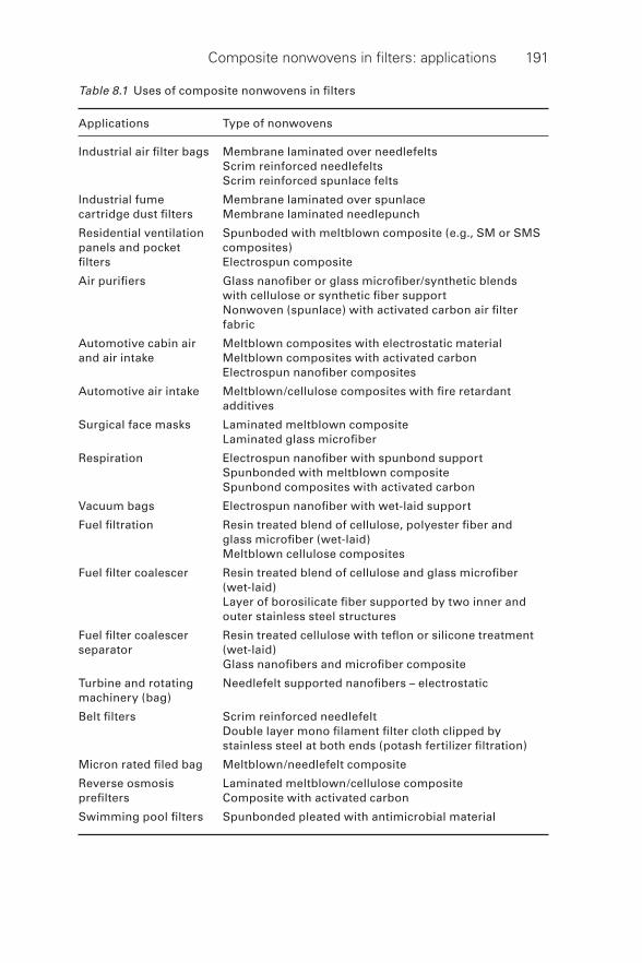
Composite nonwovens in fi lters: applications 191
Table 8.1 Uses of composite nonwovens in fi lters
Applications Type of nonwovens
Industrial air fi lter bags Membrane laminated over needlefelts Scrim reinforced needlefelts Scrim reinforced spunlace felts
Industrial fume cartridge dust fi lters
Membrane laminated over spunlace Membrane laminated needlepunch
Residential ventilation panels and pocket fi lters
Spunboded with meltblown composite (e.g., SM or SMS composites) Electrospun composite
Air purifi ers Glass nanofi ber or glass microfi ber/synthetic blends with cellulose or synthetic fi ber support Nonwoven (spunlace) with activated carbon air fi lter fabric
Automotive cabin air and air intake
Meltblown composites with electrostatic material Meltblown composites with activated carbon Electrospun nanofi ber composites
Automotive air intake Meltblown/cellulose composites with fi re retardant additives
Surgical face masks Laminated meltblown composite Laminated glass microfi ber
Respiration Electrospun nanofi ber with spunbond support Spunbonded with meltblown composite Spunbond composites with activated carbon
Vacuum bags Electrospun nanofi ber with wet- laid support
Fuel fi ltration Resin treated blend of cellulose, polyester fi ber and glass microfi ber (wet- laid) Meltblown cellulose composites
Fuel fi lter coalescer Resin treated blend of cellulose and glass microfi ber (wet- laid) Layer of borosilicate fi ber supported by two inner and outer stainless steel structures
Fuel fi lter coalescer separator
Resin treated cellulose with tefl on or silicone treatment (wet- laid) Glass nanofi bers and microfi ber composite
Turbine and rotating machinery (bag)
Needlefelt supported nanofi bers – electrostatic
Belt fi lters Scrim reinforced needlefelt Double layer mono fi lament fi lter cloth clipped by stainless steel at both ends (potash fertilizer fi ltration)
Micron rated fi led bag Meltblown/needlefelt composite
Reverse osmosis prefi lters
Laminated meltblown/cellulose composite Composite with activated carbon
Swimming pool fi lters Spunbonded pleated with antimicrobial material
192 Composite Nonwoven Materials
evolving as a result of market development and demand and this need for new products and technologies continues to grow. Disruptive technologies such as nanofi bers are essential to growth and new product development across a range of fi elds, fueled by market responses, and the development of any new composite fi lter media would also originate from market needs or ideas. Looking at current market needs (Scoble, 2011) such developments may include:
• Non- polytetrafl uoroethylene (PTFE) membranes. • Fibers capable of communication through alteration (for example by changing
color) to highlight potential problems such as exposure to toxins, excess temperature or dangerous wear levels).
• Fibers which could convert and/or neutralize pollutants, toxins, CO or other harmful gasses or solids.
• Fibers which could be charged and have polarity reversed, creating a textile electrostatic precipitator.
• Increased use of nanofi bers, microfi bers and splitable fi bers in an attempt to fi ll the gaps between standard, fi ne, micro- and nanofi bers.
• A longer- lasting, activated carbon coating for fi bers to rival A/C depth fi lters.
8.6 Applications in air/gas fi ltration
8.6.1 HEPA fi lter
The primary issues that are always being pursued with particulate fi lter improvements are: (i) higher effi ciency at lower energy consumption, (ii) longer fi lter life, (iii) greater dust load capacity, (iv) gaseous absorption and (v) easier maintenance without compromising fi lter effi ciency. In all these improvements, development of the composite fi lter media is of prime importance. Usually, ultra- fi ne fi lters such as HEPA and ULPA elements use a sheet form of medium produced with glass microfi bers with a graduated matrix to provide very high dust retention capacities. Nonwoven media, made from progressively structured thermally- (meltblown and spunbonded) and resin- bonded synthetic fi bers, are gaining in use over glass fi ber media. PP melt blown supported by spunbonded material are also used as HEPA fi lters. HEPA fi lter performance is found to be improved through appropriately structured meltblown nonwovens (Hassan et al. , 2012). There are many other variants of fi lter media composite structure such as the SMS (spunbond/meltblown/spunbond) process and variations thereof. The layered construction enables a gradual removal of fi ner airborne particles. In addition to being less expensive, fi lters exhibit greater durability, performance, safety, and environmental friendliness than their nonwoven glass fi ber counterparts (Thiele and Badt, 1996). In addition, some designs offer varied separation modes within a single fi lter media. In automotive cabin air fi lters, for example, a nonwoven particulate fi lter layer is often combined with an activated carbon layer, offering further removal of odors and fumes.
Composite nonwovens in fi lters: applications 193
For higher effi ciency at lower energy consumption, the use of the layered fabric concept is also reported, where layers of fi ner denier fi bers or even nanofi bers can be incorporated in the fabric structure. Various fi ner fi ber layers can be positioned at different locations within composite fi lter media to enhance the performance of HEPA fi lters. With Hollingsworth & Vose’s (2013) nanoweb process, nanoweblayers (thickness in the range of 15 to 30 μm) can be applied directly to a fi ltration substrate, such as glass, cellulose or synthetic fi bers. A second nanofi ber layer of a similar or different polymer can also be applied as a coating (Leung and Hung, 2012). NanoWave®, extended surface synthetic media has been reported to meet ASHRAE bag standards and HEPA/ULPA challenges (Anon, 2008; Wertz and Schneiders, 2009).
In recent years, developments in fi bers and process technologies have expanded the applications of stitch bonded, hydroentangled composite nonwoven fabrics in fi ltration (Schmalz, 1998). The use of composites in fi lter cartridges (pleated cylindrical shape) which exhibit a fabric outer fi lter and a PTFE inner membrane is also reported (Dotti et al. , 2007). In another development, polymeric fi bers are mixed with glass fi bers which can make the structure pliable and can add a signifi cant amount of structural strength that allows pleating to be effective (Larzelere, 2006). This will enhance the fi ltration performance of HEPA fi lter media in a smaller space.
8.6.2 Industrial fi lters
Investigating methods for enhancing surface fi ltration is a common approach taken in developing industrial fi lter media. Although there have already been great improvements to the basic nonwoven structure, various methods to further enhance surface fi ltration are also available, in addition to the layered nonwoven fabric of membranes or coatings, fi ne/nanofi bers, or trilobal/multilobal fi bers at the upstream side. Of the several available techniques, membrane fi lters are becoming most frequently used for controlling fi ne particulates. As well as PTFE fi lter membranes increasing production costs, further research is still needed into their mechanical strength and subsequently their lifespan. As such, research and development related to this membrane arguably represents the fastest growing area of the fi ltration media market.
A variety of other composite forms are also being employed in industrial gaseous fi ltration. Use of metallic wire mesh inside the nonwoven structure is prevalent for dissipation of static charges in some specifi c industries. There is growing interest of using scrim needlefelt fabric, particularly in high temperature applications. Advanced composite products of this type will undoubtedly feature strongly as a future trend in this fi eld, and the development of such products will facilitate the formation of structures that are not only more effi cient in particle capture, but also have an increased fi lter life and enhanced performance capability in more chemically and thermally challenging environments. Combined, these benefi ts translate into operational cost savings and greater control of environmental pollution.
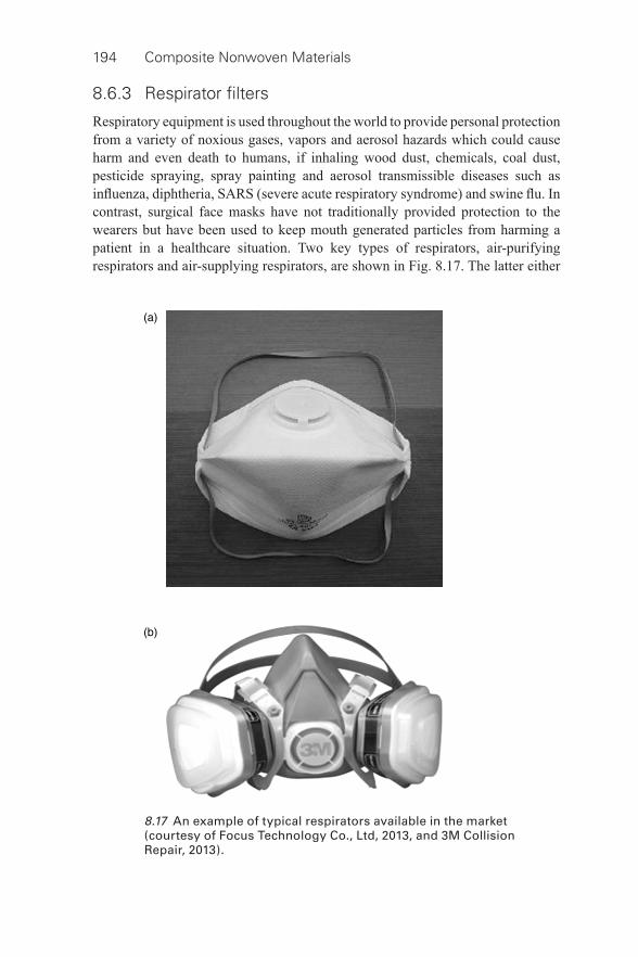
194 Composite Nonwoven Materials
8.6.3 Respirator fi lters
Respiratory equipment is used throughout the world to provide personal protection from a variety of noxious gases, vapors and aerosol hazards which could cause harm and even death to humans, if inhaling wood dust, chemicals, coal dust, pesticide spraying, spray painting and aerosol transmissible diseases such as infl uenza, diphtheria, SARS (severe acute respiratory syndrome) and swine fl u. In contrast, surgical face masks have not traditionally provided protection to the wearers but have been used to keep mouth generated particles from harming a patient in a healthcare situation. Two key types of respirators, air- purifying respirators and air- supplying respirators, are shown in Fig. 8.17 . The latter either
8.17 An example of typical respirators available in the market (courtesy of Focus Technology Co., Ltd, 2013, and 3M Collision Repair, 2013).
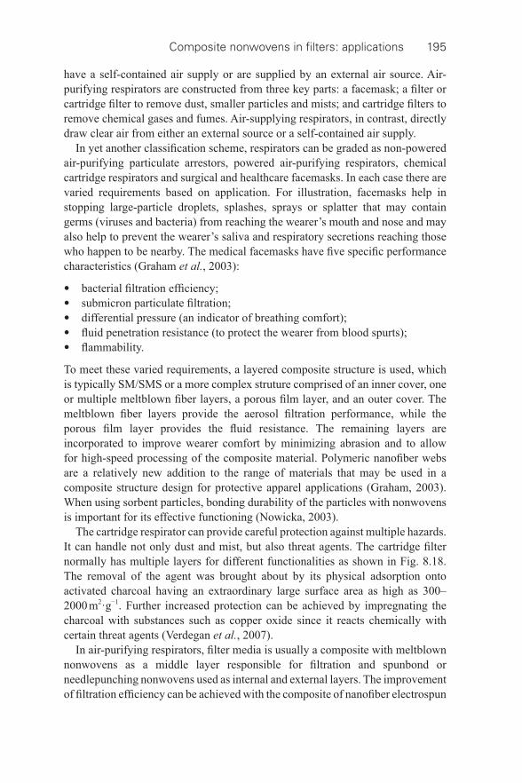
Composite nonwovens in fi lters: applications 195
have a self- contained air supply or are supplied by an external air source. Air- purifying respirators are constructed from three key parts: a facemask; a fi lter or cartridge fi lter to remove dust, smaller particles and mists; and cartridge fi lters to remove chemical gases and fumes. Air- supplying respirators, in contrast, directly draw clear air from either an external source or a self- contained air supply.
In yet another classifi cation scheme, respirators can be graded as non- powered air- purifying particulate arrestors, powered air- purifying respirators, chemical cartridge respirators and surgical and healthcare facemasks. In each case there are varied requirements based on application. For illustration, facemasks help in stopping large- particle droplets, splashes, sprays or splatter that may contain germs (viruses and bacteria) from reaching the wearer’s mouth and nose and may also help to prevent the wearer’s saliva and respiratory secretions reaching those who happen to be nearby. The medical facemasks have fi ve specifi c performance characteristics (Graham et al. , 2003):
• bacterial fi ltration effi ciency; • submicron particulate fi ltration; • differential pressure (an indicator of breathing comfort); • fl uid penetration resistance (to protect the wearer from blood spurts); • fl ammability.
To meet these varied requirements, a layered composite structure is used, which is typically SM/SMS or a more complex struture comprised of an inner cover, one or multiple meltblown fi ber layers, a porous fi lm layer, and an outer cover. The meltblown fi ber layers provide the aerosol fi ltration performance, while the porous fi lm layer provides the fl uid resistance. The remaining layers are incorporated to improve wearer comfort by minimizing abrasion and to allow for high- speed processing of the composite material. Polymeric nanofi ber webs are a relatively new addition to the range of materials that may be used in a composite structure design for protective apparel applications (Graham, 2003). When using sorbent particles, bonding durability of the particles with nonwovens is important for its effective functioning (Nowicka, 2003).
The cartridge respirator can provide careful protection against multiple hazards. It can handle not only dust and mist, but also threat agents. The cartridge fi lter normally has multiple layers for different functionalities as shown in Fig. 8.18 . The removal of the agent was brought about by its physical adsorption onto activated charcoal having an extraordinary large surface area as high as 300–2000 m 2 ·g −1 . Further increased protection can be achieved by impregnating the charcoal with substances such as copper oxide since it reacts chemically with certain threat agents (Verdegan et al. , 2007).
In air- purifying respirators, fi lter media is usually a composite with meltblown nonwovens as a middle layer responsible for fi ltration and spunbond or needlepunching nonwovens used as internal and external layers. The improvement of fi ltration effi ciency can be achieved with the composite of nanofi ber electrospun
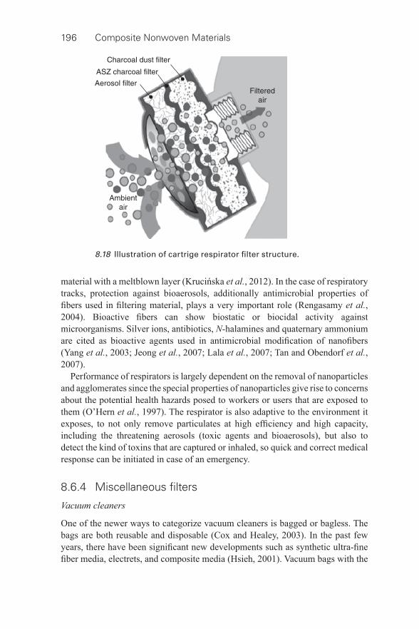
196 Composite Nonwoven Materials
material with a meltblown layer (Krucińska et al. , 2012). In the case of respiratory tracks, protection against bioaerosols, additionally antimicrobial properties of fi bers used in fi ltering material, plays a very important role (Rengasamy et al. , 2004). Bioactive fi bers can show biostatic or biocidal activity against microorganisms. Silver ions, antibiotics, N- halamines and quaternary ammonium are cited as bioactive agents used in antimicrobial modifi cation of nanofi bers (Yang et al. , 2003; Jeong et al. , 2007; Lala et al. , 2007; Tan and Obendorf et al. , 2007).
Performance of respirators is largely dependent on the removal of nanoparticles and agglomerates since the special properties of nanoparticles give rise to concerns about the potential health hazards posed to workers or users that are exposed to them (O’Hern et al. , 1997). The respirator is also adaptive to the environment it exposes, to not only remove particulates at high effi ciency and high capacity, including the threatening aerosols (toxic agents and bioaerosols), but also to detect the kind of toxins that are captured or inhaled, so quick and correct medical response can be initiated in case of an emergency.
8.6.4 Miscellaneous fi lters
Vacuum cleaners
One of the newer ways to categorize vacuum cleaners is bagged or bagless. The bags are both reusable and disposable (Cox and Healey, 2003). In the past few years, there have been signifi cant new developments such as synthetic ultra- fi ne fi ber media, electrets, and composite media (Hsieh, 2001). Vacuum bags with the
8.18 Illustration of cartrige respirator fi lter structure.
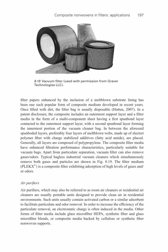
Composite nonwovens in fi lters: applications 197
fi lter papers enhanced by the inclusion of a meltblown substrate lining has been one such popular form of composite medium developed in recent years. Once fi lled with dirt, the fi lter bag is usually disposable (Hutten, 2007). In a patent disclosure, the composite includes an outermost support layer and a fi lter media in the form of a multi- component sheet having a fi rst spunbond layer contacted to the outermost support layer, with a second spunbond layer forming the innermost portion of the vacuum cleaner bag. In between the aforesaid spunboded layers, preferably four layers of meltblown webs, made up of electret polymer fi ber with charge stabilized additives (fatty acid amide), are placed. Generally, all layers are composed of polypropylene. The composite fi lter media have enhanced fi ltration performance characteristics, particularly suitable for vacuum bags. Apart from particulate separation, vacuum fi lter can also remove gases/odors. Typical bagless industrial vacuum cleaners which simultaneously remove both gases and particles are shown in Fig. 8.19 . The fi lter medium (PLEKX® ) is a composite fi lter exhibiting adsorption of high levels of gases and/or odors.
Air purifi ers
Air purifi ers, which may also be referred to as room air cleaners or residential air cleaners are usually portable units designed to provide clean air in residential environments. Such units usually contain activated carbon or a similar adsorbent to facilitate particulate and odor removal. In order to increase the effi ciency of the particulate removal, an electrostatic charge is often induced in the media. Other forms of fi lter media include glass microfi ber HEPA, synthetic fi ber and glass microfi ber blends, or composite media backed by cellulose or synthetic fi ber nonwoven supports.
8.19 Vacuum fi lter (used with permission from Graver Technologies LLC).
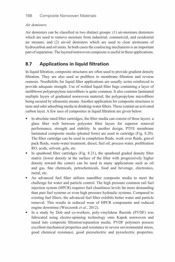
198 Composite Nonwoven Materials
Air demisters
Air demisters can be classifi ed in two distinct groups: (1) air- moisture demisters which are used to remove moisture from industrial, commercial, and residential air streams; and (2) air- oil demisters which are used to clear airstreams of hydrocarbon and oil mists. In both cases the coalescing mechanism is an important part of separation. The layered nonwoven composite is useful in these applications.
8.7 Applications in liquid fi ltration
In liquid fi ltration, composite structures are often used to provide gradient density fi ltration. They are also used as prefi lters to membrane fi ltration and reverse osmosis. Needlefelts for liquid fi lter applications are usually scrim reinforced to provide adequate strength. Use of welded liquid fi lter bags containing a layer of meltblown polypropylene microfi bers is quite common. It also contains laminated multiple layers of graduated nonwoven material; the polypropylene microfi bers being secured by ultrasonic means. Another application for composite structures is taste and odor adsorbing media in drinking- water fi lters. These contain an activated carbon layer. A few uses of composites in liquid fi ltration are given below:
• In absolute rated fi lter cartridges, the fi lter media can consist of three layers: a glass fi ber web between polyester fi lter layers for superior removal performance, strength and stability. In another design, PTFE membrane laminated composite media (pleated form) are used in cartridge ( Fig. 8.20 ). The fi lter cartridge can be used in completion fl uids, work over fl uids, gravel pack fl uids, waste- water treatment, diesel, fuel oil, process water, prefi ltration RO, acids, solvent, gels, etc.
• In spunbond fi lter cartridges ( Fig. 8.21 ), the spunbond graded density fi lter matrix (lower density at the surface of the fi lter with progressively higher density toward the center) can be used in many applications such as oil and gas, fi ne chemicals, petrochemicals, food and beverage, electronics, metal, etc.
• An advanced fuel fi lter utilizes nanofi ber composite media to meet the challenge for water and particle control. The high pressure common rail fuel injection system (HPCR) requires fuel cleanliness levels far more demanding than past fuel systems or even high pressure hydraulic systems. Compared to existing fuel fi lters, the advanced fuel fi lter exhibits better water and particle removal. This results in reduced wear of HPCR components and reduced engine downtime (Wieczorek et al. , 2012).
• In a study by Doh and co- workers, poly- vinylidene fl uoride (PVDF) was fabricated using electro- spinning technology onto Kapok nonwoven and tuned into composite fi ltration/separation media. PVDF polymers possess excellent mechanical properties and resistance to severe environmental stress, good chemical resistance, good piezoelectric and pyroelectric properties.
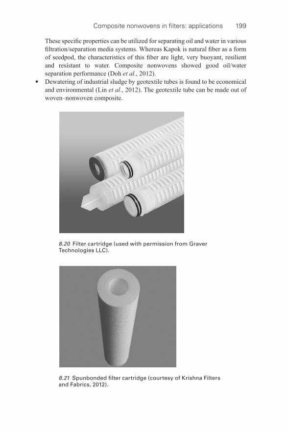
Composite nonwovens in fi lters: applications 199
These specifi c properties can be utilized for separating oil and water in various fi ltration/separation media systems. Whereas Kapok is natural fi ber as a form of seedpod, the characteristics of this fi ber are light, very buoyant, resilient and resistant to water. Composite nonwovens showed good oil/water separation performance (Doh et al. , 2012).
• Dewatering of industrial sludge by geotextile tubes is found to be economical and environmental (Lin et al. , 2012). The geotextile tube can be made out of woven–nonwoven composite.
8.20 Filter cartridge (used with permission from Graver Technologies LLC).
8.21 Spunbonded fi lter cartridge (courtesy of Krishna Filters and Fabrics, 2012).
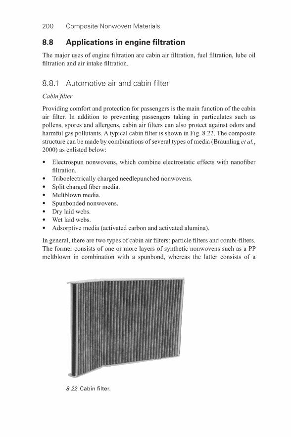
200 Composite Nonwoven Materials
8.8 Applications in engine fi ltration
The major uses of engine fi ltration are cabin air fi ltration, fuel fi ltration, lube oil fi ltration and air intake fi ltration.
8.8.1 Automotive air and cabin fi lter
Cabin fi lter
Providing comfort and protection for passengers is the main function of the cabin air fi lter. In addition to preventing passengers taking in particulates such as pollens, spores and allergens, cabin air fi lters can also protect against odors and harmful gas pollutants. A typical cabin fi lter is shown in Fig. 8.22 . The composite structure can be made by combinations of several types of media (Bräunling et al. , 2000) as enlisted below:
• Electrospun nonwovens, which combine electrostatic effects with nanofi ber fi ltration.
• Triboelectrically charged needlepunched nonwovens. • Split charged fi ber media. • Meltblown media. • Spunbonded nonwovens. • Dry laid webs. • Wet laid webs. • Adsorptive media (activated carbon and activated alumina).
In general, there are two types of cabin air fi lters: particle fi lters and combi- fi lters. The former consists of one or more layers of synthetic nonwovens such as a PP meltblown in combination with a spunbond, whereas the latter consists of a
8.22 Cabin fi lter.
Composite nonwovens in fi lters: applications 201
composite of synthetic nonwovens (particle fi lter and support layer) and activated carbon (Maltha et al. , 2012). In order to apply spunbond nonwovens as a support layer or prefi lter for cabin air fi lter media, the following important performance requirements must be satisfi ed:
• high air permeability for the lowest pressure drop (energy savings); • good coverage in the case of activated carbon fi lters; • high stiffness to get optimal pleats; • high dimensional stability for good processing and stable pleats; • good adhesion to the fi lter medium such as a PP meltblown.
All these performance requirements are important for good fi lter media effi ciency. Because of the unique manufacturing process of the bicomponent nonwoven, it is possible to tune its properties in such a way that the nonwoven gets optimal properties for specifi c fi ltration applications (Maltha et al. , 2012). Recently, more and more nanofi ber/bicomponent/meltblown media are combined for particle fi ltration, whether purely mechanical or electrostatically charged or a combination thereof, with the benefi ts of activated carbon. These combined fi lters not only stop particles but also absorb a multitude of gasses and odors. New developments in the manufacturing of nonwoven media containing activated carbon, which tightly encapsulates the carbon particles, now allow manufacturers to easily pleat these media and hence design fi lters for a wide variety of shapes and sizes. By means of activated carbon applied over fl at and even layers on various textiles (Diederich, 2011) odors and VOCs in the automotive interior can be controlled. Different activated carbons can be used according to what substances and how much gas and odor fi ltration are required to be adsorbed. As typical cabin air fi lters cannot catch emissions in the car interior, especially when the car is stationary, car interiors can be made out of the composite containing activated carbon. The increasing public awareness of air quality is expected to move cabin air fi lters into more and more cars, therefore further expanding this market (Barrillon, 2005).
The Hollingsworth & Vose Company, Inc. (2013) promotes adsorptive fi lter media with multilayered structures that remove vapors and gases from the air space. Their media can be combined with almost all particulate fi ltration media and scrims. Ahlstrom products (2013) has designed its Trinetex® technology for particulate fi ltration of cabin air. This unique technology employs a gradient density effect to increase dirt- holding capacity, through a design consisting of a three- layer wet- laid medium. In order to provide optimized fi ltration effi ciency, mechanical and electrostatic fi ltration are combined, whilst fl ame retardancy and antimicrobial treatments are also available to further enhance the fi lter media.
Engine air fi lter
The purpose of an engine air induction system is to deliver clean air to the throttle body of the engine, while providing engine sound tuning with minimal power
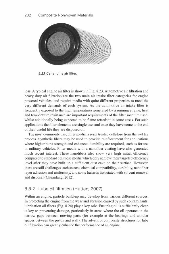
202 Composite Nonwoven Materials
loss. A typical engine air fi lter is shown in Fig. 8.23 . Automotive air fi ltration and heavy duty air fi ltration are the two main air intake fi lter categories for engine powered vehicles, and require media with quite different properties to meet the very different demands of each system. As the automotive air- intake fi lter is frequently exposed to the high temperatures generated by a running engine, heat and temperature resistance are important requirements of the fi lter medium used, whilst additionally being expected to be fl ame retardant in some cases. For such applications the fi lter elements are single use, and once they have come to the end of their useful life they are disposed of.
The most commonly used fi lter media is resin treated cellulose from the wet lay process. Synthetic fi bers may be used to provide reinforcement for applications where higher burst strength and enhanced durability are required, such as for use in military vehicles. Filter media with a nanofi ber coating have also generated much recent interest. These nanofi bers also show very high initial effi ciency compared to standard cellulose media which only achieve their targeted effi ciency level after they have built up a suffi cient dust cake on their surface. However, there are still challenges such as cost, chemical compatibility, durability, nanofi ber layer adhesion and uniformity, and some hazards associated with solvent removal and disposal (Chuanfang, 2012).
8.8.2 Lube oil fi ltration (Hutten, 2007)
Within an engine, particle build- up may develop from various different sources. In protecting the engine from the wear and abrasion caused by such contaminants, lubrication oil fi lters ( Fig. 8.24 ) play a key role. Ensuring oil is suffi ciently clean is key to preventing damage, particularly in areas where the oil operates in the narrow gaps between moving parts (for example at the bearings and annular spaces between the piston and wall). The advent of composite structures for lube oil fi ltration can greatly enhance the performance of an engine.
8.23 Car engine air fi lter.
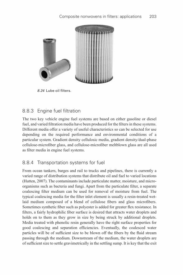
Composite nonwovens in fi lters: applications 203
8.8.3 Engine fuel fi ltration
The two key vehicle engine fuel systems are based on either gasoline or diesel fuel, and varied fi ltration media have been produced for the fi lters in these systems. Different media offer a variety of useful characteristics so can be selected for use depending on the required performance and environmental conditions of a particular system. Gradient density cellulosic media, gradient density/dual- phase cellulose- microfi ber glass, and cellulose- microfi ber meltblown glass are all used as fi lter media in engine fuel systems.
8.8.4 Transportation systems for fuel
From ocean tankers, barges and rail to trucks and pipelines, there is currently a varied range of distribution systems that distribute oil and fuel to varied locations (Hutten, 2007). The contaminants include particulate matter, moisture, and micro- organisms such as bacteria and fungi. Apart from the particulate fi lter, a separate coalescing fi lter medium can be used for removal of moisture from fuel. The typical coalescing media for the fi lter inlet element is usually a resin- treated wet- laid medium composed of a blend of cellulose fi bers and glass microfi bers. Sometimes synthetic fi ber such as polyester is added for greater fl ex resistance. In fi lters, a fairly hydrophilic fi ber surface is desired that attracts water droplets and holds on to them as they grow in size by being struck by additional droplets. Media treated with phenolic resin generally have the right surface properties for good coalescing and separation effi ciencies. Eventually, the coalesced water particles will be of suffi cient size to be blown off the fi bers by the fl uid stream passing through the medium. Downstream of the medium, the water droplets are of suffi cient size to settle gravimetrically in the settling sump. It is key that the exit
8.24 Lube oil fi lters.
204 Composite Nonwoven Materials
element or separator is extremely hydrophobic, rejecting any small water particles entrained in the fuel stream. The addition of very low energy media (such as a fl uorocarbon or silicone) as a coating for the exit elements can enhance this.
8.9 Conclusion
The development of composite nonwovens leads to improved performance of nonwovens in many areas of fi ltration.
8.10 References
3M Collision Repair ( 2013 ) Masks and Respirators . Available from: http://3mcollision.com/products/safety/masks- and- respirators/reusable- masks-and-respirators/3m- dual-cartridge- respirator-assembly-07193.html
Agar , D. W. ( 1999 ) Multifunctional reactors: old preconceptions and new dimensions , Chemical Engineering Science , 54 , 1299 – 1305 .
ALSOM Power ( 2008 ) Catalytic Filter System . Available from: www.environment.power.alstom.com [accessed 21 June 2008].
Ahlstrom Products ( 2013 ) Available from: http://www.ahlstrom.com/en/products/enduseApplication/transportation/automotiveFiltration/Pages/Cabinairfi ltration.aspx [accessed 2 June 2013 ].
Ahlstrom Technical Specialties, PA, USA ( 2001 ) ‘ Science & Technology of Filtration and Separations for the 21st Century ,’ Fourteenth Annual Technical Conference and Exposition , FL, USA , 1–4 May 2001 .
Ahn , Y. C. , Park , S. K. , Kim , G. T. , Hwang , Y. J. , Lee , C. G. and Shin , H. S. ( 2006 ) Development of high effi ciency nanofi lters made of nanofi bers , Current Applied Physics , 6 , 1030 – 1035 .
Anon ( 2008 ) Show preview: Index 2008 , Filtration & Separation , 45 ( 2 ) 18 – 21 . Austin Air Filters ( 2013 ) 3 Layers of Revolutionary Protection , Austin Air Systems Ltd .
Available from: http://www.endalldisease.com/austin- air-fi lters-3-layers- of-revolutionary- protection/ [accessed 12 March 2013].
Barhate , R. S. and Ramakrishna , S. ( 2007 ) Nanofi brous fi ltering media: fi ltration problems and solutions from tiny materials , J. Membrane Science , 296 , 1 – 8 .
Barrillon , J. ( 2005 ) Automotive fi ltration: a new horizon for nonwovens , Filtration & Separation , 42 ( 9 ) 28 – 30 .
Bonte , J. L. , Fritsky , K. J. , Plinke , M. A. and Wilken , M. ( 2002 ) Catalytic destruction of PCDD/F in a fabric fi lter: experience at a municipal waste incinerator in Belgium , Waste Management , 22 , 421 – 426 .
Bräunling , V. , Yung , A. , Miller , D. and Kalets , J. ( 2000 ) A brief overview of cabin air fi ltration , AFSS Adv. Filtr. Sep. Technol. , 14 .
Callé , S. , Contal , P. , Thomas , D. , Bémer , D. and Leclerc , D. ( 2002 ) Evolutions of effi ciency and pressure drop of fi lter media during clogging and cleaning cycles , Powder Technology , 128 , 213 – 217 .
Carr , R. C. and Smith , W. C. ( 1984 ) Fabric fi lter technology for utility coal fi red power plants (Part III): Performance of full scale utility bag house , J. Air Pollution Control Assoc. , 34 , 281 – 293 .
Centers for Disease Control and Prevention, Atlanta, USA ( 2003 ) Guidance for Filtration and Air-Cleaning Systems to Protect Building Environments from Airborne Chemical,
Composite nonwovens in fi lters: applications 205
Biological, or Radiological Attacks , DHHS (NIOSH) Publication No. 2003–136, April 2003 . Available from: http://www.cdc.gov/niosh/docs/2003–136/ [accessed 4 January 2013].
Chuanfang , Y. ( 2012 ) Aerosol Filtration Application Using Fibrous Media—An Industrial Perspective , Chinese Journal of Chemical Engineering , 20 ( 1 ) 1 – 9 .
Chung , H. Y. , Hall , J. R. B. , Gogins , M. A. , Crofoot , D. G. and Weik , T. M. ( 2008 ) Bag house fi lter with fi ne fi ber and spun bonded media , US Patent 7318852 , 15 January 2008 .
Ciach , T. and Gradon , L. ( 1998 ) Multilayer fi brous fi lters with varied porosity and fi ber diameter , J. Aerosol Science , 29 , S935 – S936 .
Connor , R. O. ( 1997 ) Fabric selection for hot gas and other applications: effi ciencies and economics , Filtration & Separation , 34 ( 8 ) 834 – 837 .
Coulson , S. R. and Evans , D. R. ( 2011 ) ‘ Oil Repellent Nano-Coatings for Increased Filtration Performance ,’ FILTECH 2011 Conference Proceedings , Wiesbaden, Germany , 22–24 March 2011 , II 126 – 132 .
Cox , S. T. and Healey , D. T. ( 2003 ) Melt blown composite HEPA fi lter media and vacuum bag , US Patent 6,524,360 B2 , 25 February 2003 .
Dascalescu , L. , Plopeanu , M. , Tabti , B. , Antoniu , A. , Dumitran , L-M. and Notingher, P. V. ( 2010 ) Corona Charging of Composite Non-Woven Media for Air Filtration , Proceedings of the ESA Annual Meeting on Electrostatics 2010 . Available from: http://www.electrostatics.org/images/ESA2010_D3_Dascalescu.pdf [accessed 4 January 2013].
Dautzemberg , F. M. and Mukherjee , M. ( 2001 ) Process intensifi cation using multifunctional reactors , Chemical Engineering Science , 56 , 251 – 267 .
Dewsbury , M. E. ( 1990 ) ‘ Market Opportunities with Superabsorbent Fibers File ,’ TAPPI 1990 Nonwovens Conference . Available from: http://www.tappi.org/Downloads/unsorted/UNTITLED-91feb146pdf.aspx [accessed 4 January 2013].
Di , Y. , Li , Q. and Zhuang , X. ( 2012 ) Antibacterial Finishing of Tencel/Cotton Nonwoven Fabric Using Ag Nanoparticles–Chitosan Composite , J. Engineered Fibers and Fabrics , 7 ( 2 ), 24 – 29 . Available from: http://www.jeffjournal.org [accessed 4 January 2013].
Diederich , F. ( 2011 ) ‘ Loaded Adsorption Filter – A Solution for Purgeable, Volatile Components and Odours in Automotive Interiors? ,’ FILTECH 2011 Conference Proceedings , Wiesbaden, Germany , 22–24 March 2011 , II 357 – 363 .
Doh , S. J. , Choi , Y. O. , Yoon , Y. H. and Lim , D. Y. ( 2012 ) ‘ Application of Kapok Nonwoven and Electrospun Pvdf Nanofi ber Web to Oil/Water Separation ,’ 11th World Filtration Congress , 16–20 April, 2012 , Graz, Austria .
Dotti , F. , Varesano , A. , Montarsolo , A. , Aluigi , A. , Tonin , C. and Mazzuchetti , G. ( 2007 ) Electrospun porous mats for high effi ciency fi ltration , J. Industrial Textiles , 37 ( 2 ) 151 – 162 .
Fagan , J. P. ( 1982 ) Felt- like layered composite of PTFE and glass paper, US Patent 4,324,574 , 13 April 1982 .
Fino , D. , Russo , N. , Saracco , G. and Specchia , V. ( 2004 ) A multifunctional fi lter for the simultaneous removal of fl y- ash and NO x from incinerator fl ue gases , Chemical Engineering Science , 59 , 5329 – 5336 .
Focus Technology Co., Ltd. ( 2013 ) Safety products and supplies . Available at http://chinamachine.en.made- in-china.com/product/mqSxzHOMXEVX/China-Face-Mask-Protective-Swine-Flu-A-H1N1-.html
Freudenberg Filtration Technologies, Weinheim, Germany ( 2013 ) Scanning Electron Microscope (SEM) image of a carbon activated fi lter medium . Available at http://www.corteco.com/en/press/photos/cabin- air-fi lters/ [accessed 15 March 2013].
206 Composite Nonwoven Materials
Fritsky , K. J. ( W. L. Gore & Associates, Inc.) ( 2013 ) Long-Term Performance of GORE-TEXMembrane Filter Bags at a Municipal Solid Waste Combustion Facility . Available from: http://www.gore.com/MungoBlobs/article_fi lter_municipal_solid_waste,6.pdf [accessed 2 March 2013].
Galka , N. and Saxena , A. ( 2009 ) High effi ciency air fi ltration: the growing impact of membranes , Filtration & Separation , 46 ( 4 ) 22 – 25 .
Gibson , P. , Gibson , H. S. and Rivin , R. ( 2001 ) Transport properties of porous membranes based on electrospun nanofi bers , Colloids Surf. A: Physicochem. Eng. Aspects , 187 – 188 , 469 – 481 .
Gibbons , S. ( 2002 ) Why embedding the membrane within the media carrier support makes sense , Filtration & Separation , 39 ( 7 ) 20 – 22 .
Goosens , F. ( 1993 ) Improvement of surface structure of fi ltration media by bonding, laminating, coating and impregnating , J. Industrial Textiles , 22 , 279 – 289 .
Gopal , R. , Kaur , S. , Maa , Z. , Chanc , C. , Ramakrishna , S. and Matsuura , T. ( 2006 ) Electrospun nanofi brous fi ltration membrane , J. Membrane Science , 281 , 581 – 586 .
Gopal , R. , Kaur , S. , Feng , C. Y. , Chan , C. , Ramakrishna , S. , Tabe , S. and Matsuura , T. ( 2007 ) Electrospun nanofi brous polysulfone membranes as prefi lters: particulate removal , J. Membrane Science , 289 ( 1 – 2 ), 210 – 219 .
Graham , K. , Schreuder-Gibson , H. and Gogins , M. ( 2003 ) ‘ Incorporation of Electrospun Nanofi bers into Functional Structures ’, Presented at INTC 2003, sponsored by INDA, Association of the Nonwoven Fabrics Industry and TAPPI, Technical Association of the Pulp & Paper Industry , 15–18 September , Baltimore, MD .
Griffi n , J. W. (Donaldson Company, Inc.) 2003 , Laminate and pulse jet fi lter bag, US Patent 6517919 , 11 February 2003 .
Hackel , M. , Schaub , G. , Nacken , M. and Heidenreich , S. ( 2005 ) ‘ Kinetics of reduction and oxidation reactions for application in catalytic gas- particle fi lters, in advanced gas cleaning technology ’, in C. Kanaoka , H. Makino and H. Kamiya (eds), Proceedings of the 6th International Symposium on Gas Cleaning at High Temperatures , 20–22 October 2005 , Osaka, Japan , 37 .
Hardman , E. ( 2000 ) ‘ Textile in fi ltration ’, in A. R. Horrocks and S. C. Anand (eds), Handbook of Technical Textiles . Woodhead Publishing Ltd. , The Textile Institute, CRC Press, UK .
Hassan , M. A. , Yeom , B. Y. , Wilkie , A. , Pourdeyhimi , B. and Khan , S. A. ( 2012 ) Fabrication of nanofi ber meltblown membranes and their fi ltration properties , J. Membrane Science , 427 , 336 – 344 .
Hegde , C. , Isloor , A. M. and Padaki , M. ( 2011 ) Synthesis and performance characterization of PS-PPEES nanoporous membranes with nonwoven porous support , Arabian Journal of Chemistry . Available from: http://dx.doi.org/10.1016/j.arabjc.2011.05.014 [accessed 4 May 2013].
Heidenreich , S. , Nacken , M. , Hackel , M. and Schaub , G. ( 2008 ) Catalytic fi lter elements for combined particle separation and nitrogen oxides removal from gas streams , Powder Technology , 180 , 86 – 90 .
Hoda , N. , Karaağaçlι , M. and Topel , Ö ( 2012 ) ‘ Antibacterial HEPA Filter Using Pan/silver Nanoparticle Hybrid Nanofi bers ’, 11th World Filtration Congress , 16–20 April 2012 , Graz, Austria .
Hollingsworth & Vose ( 2013 ) Cabin Air Filtration . Available from: http://www.hollingsworth- vose.com/en/Products/Filtration-Media/Air-Filtration1/Cabin-Air/ [accessed 2 March 2013].
Composite nonwovens in fi lters: applications 207
Hsieh , K.-C. ( 2001 ) ‘ Performance Comparison of Vacuum Cleaner Filters Made from Different Types of Filter Media ’, AFSS 14th Annual Technical Conference and Exposition , May 2001 .
Hutten , I. M. ( 2007 ) Handbook of Nonwoven Filter Media , Elsevier, Oxford . Jeong , E. H. , Yang , J. and Youk , J.-H. ( 2007 ) Preparation of polyurethane cationomer
nanofi ber mat for use in antimicrobial nanofi lter applications , 61 ( 18 ), 3991 – 3994 . Joeger , T. K. , Joeger , R. , Olsson , E. and Granqvist , C. G. ( 2001 ) Bacteria as workers in the
living factory: metal- accumulating bacteria and their potential for materials science , Trades in Biotechnology , 19 , 15 – 20 .
Johnson , J. and Handy , J. ( 2003 ) Breathing new life into dust collection fi lters , Ceramic Industry , 153 ( 2 ), 39 – 41 .
Kattamuri , N. , Shin , J. H. , Kang , B. , Lee , C. G. , Lee , J. K. and Sung , C. ( 2005 ) Development and surface characterization of positively charged fi lters , J. Materials Science , 40 , 4531 – 4539 .
Kosminder , K. and Scott , J. S. ( 2002 ) Polymeric nanofi bers exhibit an enhanced air fi ltration performance , Filtration & Separation , 39 ( 6 ), 20 – 22 .
Kothari , V. K. , Mukhopadhyay , A. and Pandey , S. N. ( 1993 ) Filtration characteristics of layered needle punched nonwoven fabrics , Melliand Textilberichte , 74 , 386 – 389 .
Krishna Filters and Fabrics ( 2012 ) Spun Bond Filter Cartridge . Available at http://www.krishnafi ltersandfabrics.com/product/Ahmedabad/Spun-Bonded-Filter-Cartridge/18
Krucińska , I. , Gliścińska , E. , Krzyżanowski , J. , Łysiak , I. , Gutarowska , B. and Brycki , B. ( 2012 ) ‘ Modifi cations of Nonwoven Filtering Materials by Bioactive Nanofi bers ’, 11th World Filtration Congress – Session G23 – Filter Media II , 16–20 April 2012 , Graz, Austria .
Lala , N. L. , Ramaseshan , R. , Bojun , L. , Sundarrajan , S. , Barhate , R. S. , Ying-Jun , L. and Ramakrishna , S. ( 2007 ) Fabrication of nanofi bers with antimicrobial functionalty used as fi lters: protection against bacterial contaminants , Biotechnology and Bioengineering , 97 ( 6 ), 1357 – 1365 .
Larzelere , J. ( 2006 ) New and novel technologies in particulate fi ltration , Naval Surface Warfare Center , Dahlgren Division, Dahlgren, VA . Available from: www.dtic.mil/cgi- bin/GetTRDoc?AD=ADA449780 [accessed 4 January 2013].
Legein , F. ( 2011 ) ‘ Innovative Low Pressure Plasma Coatings for Gas and Liquid Filter Media ’, FILTECH 2011 Conference Proceedings , Wiesbaden, Germany , 22–24 March 2011 , I 98 – 106 .
Leung , W. W-F. and Hung , C-h. ( 2012 ) ‘ Performance of Pleated Nanofi ber Filter ’, 11th World Filtration Congress , 16–20 April 2012 , Graz, Austria .
Lin , J. H. , Lou , C. W. , Lei , C. H. and Lin , C. Y. ( 2006 ) Processing conditions of abrasion and heat resistance for hybrid needle- punched nonwoven bag fi lters , Composites: Part A (Applied Science and Manufacturing) , 37 , 31 – 37 .
Lin , Z. , Wu , S. and Chien , A. ( 2012 ) ‘ Industrial Sludge Dewatering Using Geotextile Tubes ’, 11th World Filtration Congress , 16–20 April 2012 , Graz, Austria .
Lydall Filtration and Separation ( 2013 ) ‘ Nonwoven Liquid Filtration Media Construction and Performance , 6th IFC, Rochester, USA . Available from: http://www.lydallfi ltration.com/tech/documents/Nonwovenliquidfi ltration.pdf [accessed 5 March 2013].
Lydon , R. ( 2004 ) Filter media surface modifi cation technology: state of the art , Filtration & Separation , 41 ( 9 ), 20 – 21 .
Maltha , A. ( 2011 ) ‘ Cabin Air Filter Media with Bicomponent Spunbond Support Layer ’, FILTECH 2011 Conference Proceedings , Wiesbaden, Germany , 22–24 March 2011 , II 343 – 348 .
208 Composite Nonwoven Materials
Maltha , A. , Berkhout , E. , van der Molen , L. and Koerntjes , M. ( 2012 ) ‘ Enhanced Performance of Cabin Air Filter Media with a Bicomponent Spunbond Nonwoven ’, 11th World Filtration Congress , 16–20 April 2012 , Graz, Austria .
Martin , C. T. ( 1999 ) ‘ Fine Filtration Fabric Options Designed for Better Dust Control and to Meet PM 2.5 Standards , 1999 IEEE-IAS/PCA Cement Industry Technical Conference , 11–15 April , Roanoke, Virginia , IEEE Catalog Number 99CH36335, pp. 385 – 393 .
Matatov-Meytal, Y. and Sheintuch , M. ( 2002 ) Catalytic fi bers and cloths , Applied Catalysis A: General , 231 , 1 – 16 .
Maus , R. , Goppelsröder , A. and Umhauer , H. ( 2001 ) Survival of bacterial and mold spores in air fi lter media , Atmospheric Environment , 35 , 105 – 113 .
Medvedyev , O. and Tsybulya , Y. ( 2005 ) Basalt use in hot gas fi ltration , Filtration & Separation , 42 ( 1 ), 34 – 37 .
Menardi Filters, South Carolina, USA ( 2013 ) Technical information . Available from: www.menardifi lters.com [accessed 4 May 2013].
Montefusco , F. ( 2005 ) The use of nonwovens in air fi ltration , Filtration and Separation , 42 ( 2 ), 30 – 31 .
Mukhopadhyay , A. ( 2009 ) Pulse- jet fi ltration: an effective way to control industrial pollution. Part I: Theory, selection and design of pulse- jet fi lter , Textile Progress , 41 ( 4 ), Taylor & Francis, UK .
Mueller sales US ( 2013 ) Membrane Filters . Available from: www.muellersales.com/pdf/sen_ptfe_polypro.pdf [accessed 2 March 2013].
Nacken , M. , Heidenreich , S. , Hackel , M. and Schaub , G. ( 2007 ) Applied Catalysis B: Environmental, 70 , 370 – 376 .
Nowicka , C. ( 2003 ) Composite nonwovens: the bonding durability of sorbent particles , Fibers & Textiles in Eastern Europe , 11 ( 3 ), 46 – 49 . Available from: http://www.fi btex.lodz.pl/42_14_46.pdf [accessed 4 May 2013].
O’Hern , M. R. , Dashiell , T. R. and Tracy , M. F. ( 1997 ) ‘ Chemical defense equipment ’, in Medical Aspects of Chemical and Biological Warfare , F. R. Sidell , E. T. Takafuji , and D. R. Franz (eds), Borden Institute, Maryland , 361 – 396 .
Podgorski , A. , Balazy , A. and Gradon , L. ( 2006 ) Application of nanofi bers to improve the fi ltration effi ciency of the most penetrating aerosol particles in fi brous fi lters , Chemical Engineering Science 61 , 6804 – 6815 .
Price , D. L. , Simmons , R. B. and Ahearn , D. G. ( 1997 ) Antimicrobial preservatives in air fi lter media- assessment of effi cacy and signifi cance of use , AFSS Adv. Filtr. Sep. Technol. , 11 , 384 – 389 .
Ray , T. K. ( 2004 ) Air Pollution Control in Industries – Volume I, Theory, Selection and Design of Air Pollution Control Equipments , Tech Books International , New Delhi, India .
Ravensworth Ltd., UK ( 2004 a) New Cost- effective Coatings Extends Filter Life and Effi ciency . Available from: http://wwt- magazine.info/news/news_story.asp?id=8929&channel=0 [accessed 24 March 2013].
Ravensworth Ltd., UK ( 2004 b) Ravlex increases fi lter- bag service life , Membrane Technology , No. 1 ( 2004 ), p. 4 .
Rengasamy , A. , Zhuang , Z. and BerryAnn , R. ( 2004 ) Respiratory protection against bioaerosols: literature review and research needs , AJIC , 32 ( 6 ), 345 – 354 .
Savage , T. C. , Carlozzi , R. C. and Petzoldt , O. ( 2013 ) Enhanced Aramid Felt Filter Bags with New Expanded PTFE Membrane Technology . Available from: www.gore.com/fi ltration/GORE-TEX@industrialbaghouse/article [accessed 24 March 2013].
Schmalz E. ( 1998 ) Innovative products from stitch- bonded hydroentangled nonwoven composites , Melliand International , 4 , 257 – 259 .
Composite nonwovens in fi lters: applications 209
Schmalz , E. , Fuchs , H. , Brodtka , M. and Schreiber , J. ( 2001 ) ‘ Innovative products from stitch- bonded-hydroentangled nonwoven composites for technical applications ’. Available from: http://www.technica.net/NT/NT3/StitchBondedHydroentangled.htm , NT New Textiles (Online magazine) [accessed 24 March 2013].
Scoble , C. B. (Filter Media Services, LLC) ( 2011 ) Nonwoven Filter Media – A Look Back, Trends and Future Market Needs . Available from: www.fi ltermediaservices.com/pdf/Nonwoven_Filter_Media.pdf [accessed 4 January 2013].
Shin , C. , Chase , G. G. and Reneker , D. H. ( 2005 a) Recycled expanded polystyrene nanofi bers applied in fi lter media , Colloids Surf. A: Physicochem. Eng. Aspects , 262 ( 1 – 3 ), 211 – 215 .
Shin , C., Chase , G. G. and Reneker , D. H. ( 2005 b) The effect of nanofi bers on liquid–liquid coalescence fi lter performance , AIChE J. , 51 ( 12 ), 3109 – 3113 .
Sievert , J. ( 2011 ) ‘ Nonwovens in Filtration ’, FILTECH 2011 Conference Proceedings , Wiesbaden, Germany , 22–24 March 2011 , I 50 – 60 .
Simatek A/S, Hoeng ( 2013 ) Product bulletin . Available from: http://www.simatek.dk/documents/00003.pdf [accessed 2 March 2013].
Smithies , A. and Zimmerman , W. C. ( 2005 ) High effi ciency particulate air rated vacuum bag media and an associated method of production . US Patent 6,872,233 , 29 March 2005 .
Spadaro , J. A. , Berger , T. J. and Barranco , S. D. ( 1974 ) Antibacterial effects of electrically activated vertebral implants , Antimicrobial Agents Chemotherapy , 6 , 637 – 642 .
Spivey , J. J. ( 1993 ) Catalytic bag- house fi lters , Applied Catalysis A: General , 105 ( 1993 ), N20 – 21 .
Stoffel , T. ( 2011 ) ‘ New Functionalities for Textile Media with GEA Tex Technology ’, FILTECH 2011 Conference Proceedings , Wiesbaden, Germany , 22–24 March 2011 , II 133 – 139 .
Taiwan Nitta Filter Co., Ltd. ( 2013 ) Available from: http://www.nitta.com.tw/pdfdata/e-EZ-all.pdf [accessed 4 January 2013].
Tan , K. and Obendorf , S. K. ( 2007 ) Fabrication and evaluation of electrospun nanofi brous antibacterial nylon 6 membranes , J. Membrane Science , 305 , 287 – 298 .
Testori Group ( 2013 ) Accessori e Ricambi, Tessitura Euganea. Available at http://www.tessituraeuganea.it/top/accessori/
Thiele , R. and Badt , H. ( 1996 ) New synthetic nonwoven composites for air fi ltration , Vliesstoff Nonwoven International , 11 ( 6 – 8 ), 165 – 168 .
Tobler , D. and Warner , L. ( 2005 ) Nanotech silver fi ghts microbes in medical devices , Med. Device Diagnost. Ind. ( May ). Available from: www.mddionline.com/. . ./nanotech- silver-fi ghts- microbes-medical- device [accessed 5 March 2013].
Verdegan , B. M. , Fallon , S. L. , Pardue , B. A. and Haberkamp , W. C. ( 2007 ) High perform-ance fi lter media with internal nanofi ber structure and manufacturing methodology , US Patent, 20070021021 A1 , 25 January 2007 .
Wang , J. , Kim , S. C. and Pui , D. Y. H. ( 2008 a) Figure of merit of composite fi lters with micrometer and nanometer fi bers , Aerosol Science and Technology , 42 , 722 – 728 .
Wang , J. , Kim , S. C. and Pui , D. Y. H. ( 2008 b) Investigation of the fi gure of merit for fi lters with a single nanofi ber layer on a substrate , J. Aerosol Science , 39 , 323 – 334 .
Wertz , J. and Schneiders , I. ( 2009 ) Filtration media: advantages of nanofi ber coating technology , Filtration & Separation , 46 ( 4 ), 18 – 20 .
Wieczorek , M. , Haberkamp , W. and Verdegan , B. ( 2012 ) ‘ Next Generation Diesel Fuel Filter ’, 11th World Filtration Congress , 16–20 April 2012 , Graz, Austria .

210 Composite Nonwoven Materials
W. L. Gore & Associates, US ( 2013 a) Applications of ePTFE . Available from: www.gore.com/en_xx/technology/timeline/applications_eptfe.html [accessed 2 March 2013].
W. L. Gore & Associates ( 2013 b) Adjusting Pulse System for Optimum Cleaning . Available from: www.gore.com [accessed 24 March 2013].
Yang , Q. B. , Li , D. M. , Hong , Y. L. , Li , Z. Y. , Wang , C. , Qiu , S. L. and Wei , Y. ( 2003 ) Preparation and characterization of a PAN nanofi ber containing Ag nanoparticles via electrospinning , Synthetic Metals , 137 , 973 – 974 .
Yeo , S. Y. , Lim , D. Y. , Byun , S. W., Kim , J. H. and Jeong , S. H. ( 2007 ) Design of fi lter bag media with high collection effi ciency , J. Material Science , 42 , 8040 – 8046 .
Yoon , H. , Kim , K. , Wang , X. , Fang , D. , Hsiao , B.S. and Chu , B. ( 2006 ) High fl ux ultrafi ltration membranes based on electrospun nanofi brous PAN scaffolds and chitosan coating , Polymer , 47 , 2434 – 2441 .
Yun , K. M. , Hogan , C. J. , Matsubayashi , Y. , Kawabe , M. , Iskandar , F. and Okuyama , K. ( 2007 ) Nanoparticle fi ltration by electrospun polymer fi bers , Chemical Engineering Science , 62 , 4751 – 4759 .
211
© 2014 Woodhead Publishing Limited
9 Composite nonwovens in medical applications
S . GHOSH, Indian Institute of Technology Delhi, India
DOI: 10.1533/9780857097750.211
Abstract: This chapter reviews the role of composite nonwovens in medical applications. It covers surgical gowns, clinical wearable products, wipes, wound dressings, pads, swabs, scaffolds for tissue engineering, hernia meshes, fi ltration materials, and incontinence products. Commercially available, innovatively designed composite nonwovens for various medical applications are improving the quality of life of many people. Specifi c research needs have been highlighted to further improve the effectiveness of these products. The chapter ends with some perspectives for the use of composite nonwovens in medical applications in the future.
Key words: composite nonwoven, fi bre, cell, wound, scaffold.
9.1 Introduction
Composite nonwovens are fi brous materials, in which several layers of different fi bres are either bonded together or combined with other textile components, while their felt characteristics remain predominant. Composite nonwovens are generally prepared by combining multiple fi brous layers of different types of polymers, fi bres or textile components. Integration of multiple fi brous layers can be achieved by passing them through a set of hot rollers, needle- punching, stitch- bonding, ultrasound treatment or high- frequency welding. Such nonwoven products can be tailored to meet the requirements of the following specifi c clinical applications:
• personal healthcare/hygiene products, such as surgical gowns, masks, wipes, surgical drapes and bedding;
• non- implantable medical dressings, including wound dressings and bandages; • implantable medical products, including scaffolds for tissue regeneration and
orthopaedic structures.
Nanofi brous nonwoven matrices, made by using the electrospinning technique, are beyond the scope of this article. However, extensive research work is being conducted in the development of electrospun matrices made up of composite nanofi bres for medical applications (Soliman et al. 2011; Zhang et al. 2009; Kai et al. 2013).
212 Composite Nonwoven Materials
9.2 Surgical gowns
The main function of a surgical gown is to provide an appropriate level of hygiene, comfort and protection for surgeons and healthcare workers from blood- borne pathogens. The recent prevalence of infectious diseases such as AIDS, hepatitis, and severe acute respiratory syndrome (SARS) demonstrates the critical need to develop effi cient surgical gowns, gloves and masks to ensure the highest level of protection.
A critical performance factor in protective surgical apparel relates to the ability to provide a barrier to microbial transfer from a non- sterile to a sterile side of the fabric. Microbes and pathogens can pass through the fabric, carried by dust particles or liquids such as body fl uids (blood, perspiration, etc.). According to the defi nition of the Centers for Disease Control and Prevention (CDC, USA), liquid- resistant apparel allows minimal amounts of liquid to penetrate when pressure is applied. Liquid- proof apparel does not allow any liquid to penetrate at all (Mangram et al. 1999).
There is great demand for cheap disposable gowns in the cost- conscious healthcare sector. Over the last few years various strategies for developing single- use fabrics have evolved, using spunbonded- meltblown-spunbonded (SMS), spunlace hydroentangled, triplex or bicomponent fi brous webs, with or without chemical fi nishes to resist liquid penetration. Disposable SMS fabric can be formed by sandwiching an inner thermoplastic meltblown microfi brous web between two outer nonwoven webs of substantially continuous thermoplastic spunbonded fi lament, where the spunbond layer provides strength and dimensional stability while the meltblown layer provides the barrier property. The microfi brous nonwoven meltblown layers provide a barrier impervious to pathogens in the composite nonwoven fabric. However, various surgical procedures entail an extent of splashing, liquid strike- through, aerosol generation, or applied pressure, and can be of long duration. Care should therefore be taken in selecting single- or multiple- use gowns during specifi c procedures.
Leonas and Jinkins (1997) compared eight commercially available surgical gowns, among which fi ve were disposable nonwovens and three were reusable woven fabrics. Four of the fi ve nonwoven fabrics investigated were made from polypropylene- based SMS nonwoven fabrics and hydroentangled wood pulp and polyester of spun- lace fabrics. SMS nonwovens showed better effi ciency in preventing the transmission of S. aureus and E. coli in a saline solution, as compared to woven fabrics. Lankester et al. (2002) studied the extent of bacterial penetration through disposable gowns made of spun- bonded polyester and wood pulp, as compared to reusable woven polyester gowns; the results clearly showed a comparatively inferior barrier property for reusable woven polyester fabrics. Taken together, as a very generalized conclusion (McCullough and Schoenberger 1991), polypropylene- based gowns (for example, 97–100% polypropylene, SMS laminates) provided the greatest protection against blood strike- through and
Composite nonwovens in medical applications 213
microbial penetration. Gowns composed of a single layer of nonwoven fabric provided the next highest level of effectiveness. Reusable gowns composed of 100% woven cotton provided a minimal level of protection.
9.3 Surgical facemasks and other clinical
wearable products
Other than surgical gowns, several other wearable products are currently demanding attention from researchers, such as shoe covers, caps, facemasks to be worn by surgeons during surgery, facemasks for patients or caregivers, facemasks for health workers handling outbreaks of airborne diseases (SARS virus, H1N1 fl u, bird fl u, etc.), and masks for sanitation workers working in dusty environments. Previously, all such reusable hospital garments were made using conventional textiles (cotton, cotton- polyester, etc.), but these have now been linked to increases in so- called ‘Hospital Acquired Infections’. Pathogenic bacteria present on the scalp and skin are reported to have caused epidemics (Dineen and Drusin 1973); it is therefore highly important that effi cient coverings are available during surgery. All over the world, major care is being taken to reduce patient- to-patient transmission of resistant pathogens such as methicillin- resistant Staphylococcus aureus and vancomycin- resistant Enterococcus . Nonwoven products remain the most common choice for protection, sometimes with an additional active coating.
Surgical facemasks are usually composed of three layers of an SMS nonwoven fabric, where the meltblown material acts as a fi lter. The design of most surgical masks includes three pleats/folds to allow the user to expand the mask to cover the area under the nose and under the chin. This design may be suffi cient to protect the wearer in dusty environments, but these products are not particularly effective in offering protection from airborne pandemic diseases or in environments full of aerosols.
Several new designs of respirator mask that use advanced strategies are currently coming in the healthcare markets. For example, the multiple- use respirator mask introduced by Carey International Ltd, Westerly, RI, USA, consists of a needle- punched, four- ply nonwoven fabric in which two outer layers contain silver/copper zeolite compounds permanently embedded onto the fi bres, and two inner fi ltration layers are designed to prevent microbial or particulate penetration (complying with the National Institute of Occupational Safety and Health standards N95 and N99). The outer layers have been demonstrated to kill Streptococcus pyogenes and methicillin- resistant Staphylococcus aureus and deactivate strains of H1N1 and H5N1, as well as common fl u and other viruses. The N95 masks offer 95% or higher particle fi ltration effi ciency.
The main limitation in the performance of shoe covers for clinicians and healthcare professionals is frequent rupturing during use (Carter 1990; Jones and Jakeways 1998). Blood easily soaks through many commercially available shoe covers, and better bacterial and liquid barrier properties are needed.
214 Composite Nonwoven Materials
Although all these products have been commonly used for many years (Eisen 2011), there is scope for innovation in their design. For example, facemasks for health workers involved in fl u pandemics must remain effective for at least a few weeks, but the standard single- use masks currently available remain effective for only a few hours. Effi cient pathogen monitoring and detection mechanisms should be available for these masks.
9.4 Wipes
The wipes market is experiencing massive growth, and there has been a constant stream of new nonwoven products across a number of categories, which have been innovatively applied. Examples include Procter & Gamble’s ‘Swiffer’ household fl oor wipes and L’Oreal’s make- up removal wipes ‘Revitalift’. An extensive review of wipes is given in Chapter 6 of this book.
9.5 Wound dressings, pads and swabs
Mammalian embryos and some amphibians can spontaneously regenerate their tissues after severe injury. Adult mammals typically recover from such injuries by a ‘repair’ process, eventually developing scars. At the price of wound closure, severe wound contraction and scar tissue formation often cause serious clinical complications and life- long disfi gurement for the survivor. During healing of skin wounds, a group of contractile cells (myofi broblasts) migrate in the wound bed. These cells express cytoplasmic bundles of microfi laments (stress fi bres), using which they apply contractile forces to shrink the injured site. Eventually the wound site is fi lled by an irregular dense collagen fi brous matrix (Tomasek et al. 2002). When a nonwoven matrix is implanted within the wound bed, those contractile cells migrate randomly, following the randomly oriented fi brous architecture of the nonwoven matrix. This can result in disorientation of major axes of contractile cells and the disruption of organized cell contraction at the edges of the wound. Thus, randomization of individual force vectors of contractile cells will reduce rapid contraction of wound edges ( Fig. 9.1 ). A signifi cant reduction in the number of contractile cells has also been reported when the wound is treated with a nonwoven scaffold during dermis regeneration (Murphy et al. 1990). Despite detailed understanding of wound healing mechanisms, scar- less healing in adult humans still remains a utopian concept, but extensive research is ongoing to develop bioresponsive fi brous material, such as collagen- glycosaminoglycan bicomponent fi brous web, which will be able to inhibit scar formation and cause controlled contraction (Yannas 2013).
Many basic composite nonwoven dressings are commercially available and are regularly used. These are relatively inexpensive, readily available, and versatile enough to treat several types of wounds. The simplest form is as a single nonwoven layer with a transparent waterproof backing (generally polyurethane fi lm), which
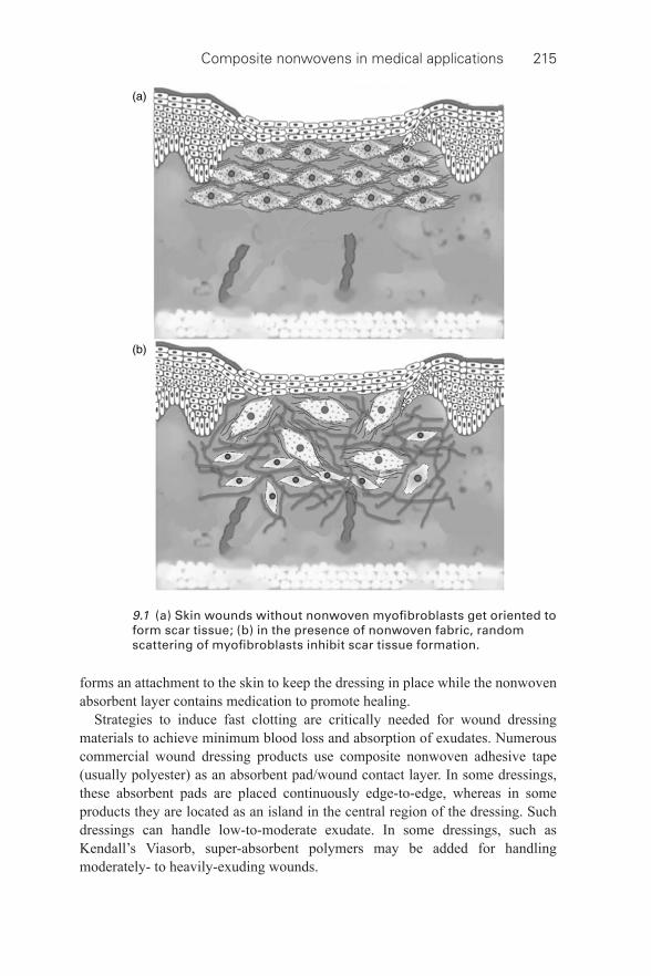
Composite nonwovens in medical applications 215
forms an attachment to the skin to keep the dressing in place while the nonwoven absorbent layer contains medication to promote healing.
Strategies to induce fast clotting are critically needed for wound dressing materials to achieve minimum blood loss and absorption of exudates. Numerous commercial wound dressing products use composite nonwoven adhesive tape (usually polyester) as an absorbent pad/wound contact layer. In some dressings, these absorbent pads are placed continuously edge- to-edge, whereas in some products they are located as an island in the central region of the dressing. Such dressings can handle low- to-moderate exudate. In some dressings, such as Kendall’s Viasorb, super- absorbent polymers may be added for handling moderately- to heavily- exuding wounds.
9.1 (a) Skin wounds without nonwoven myofi broblasts get oriented to form scar tissue; (b) in the presence of nonwoven fabric, random scattering of myofi broblasts inhibit scar tissue formation.
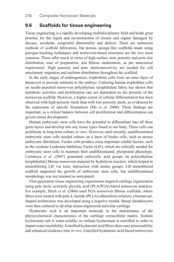
216 Composite Nonwoven Materials
9.6 Scaffolds for tissue engineering
Tissue engineering is a rapidly developing multidisciplinary fi eld and holds great promise for the repair and reconstruction of tissues and organs damaged by disease, accidents, congenital abnormality and defects. There are numerous methods of scaffold fabrication, but porous sponge- like scaffolds made using porogen- leaching techniques and nonwoven- based structures are the two most common. These offer much in terms of high surface area, porosity and pore size distribution, ease of preparation, and fi brous randomness, as per anatomical requirement. High porosity and pore interconnectivity are needed for cell attachment, migration and uniform distribution throughout the scaffold.
In the early stages of embrogenesis, trophoblast cells form an outer layer of blastocyst to provide nutrients to the embryo. Culturing human trophoblast cells on needle- punched nonwoven polyethylene terephthalate fabric has shown that metabolic activities and proliferation rate are dependent on the porosity of the nonwoven scaffold. However, a higher extent of cellular differentiation has been observed with high- porosity mesh than with low- porosity mesh, as evidenced by the expression of specifi c biomarkers (Ma et al. 2000). These fi ndings are important, as a critical balance between cell proliferation and differentiation can govern tissue development.
Human embryonic stem cells have the potential to differentiate into all three germ layers and develop into any tissue types found in our body. These cells can proliferate in long- term culture in vitro . However, until recently, undifferentiated embryonic stem cells needed culture on a layer of feeder cells, such as mouse embryonic fi broblasts. Feeder cells produce some important soluble factors, such as the cytokine Leukemia Inhibitory Factor (LIF), which are critically needed for embryonic stem cells to maintain their undifferentiated, pluripotent phenotype. Cetinkaya et al. (2007) generated carboxylic acid groups on poly(ethylene terephthalate) fi brous nonwoven material by hydrolysis reaction, which helped in immobilizing LIF via ionic interaction with amino groups. LIF-immobilized scaffold supported the growth of embryonic stem cells, but undifferentiated morphology was not retained as anticipated.
First- generation tissue engineering experiments targeted cartilage regeneration using poly lactic acid/poly glycolic acid (PLA/PGA)-based nonwoven matrices. For example, Shieh et al. (2004) used PGA nonwoven fi brous scaffolds, where fi bres were treated with poly-L-lactide (PLLA)-chloroform solution; a human ear- shaped architecture was developed using a negative mould. Sheep chondrocytes were then cultured to develop tissue- engineered auricular cartilage.
Hyaluronic acid is an important molecule in the maintenance of the physicochemical characteristics of the cartilage extracellular matrix. Sodium hyaluronate salt is water- soluble, so sodium hyaluronate is esterifi ed in order to impart water insolubility. Esterifi ed hyaluronic acid fi bres show easy processability and enhanced residence time in vivo . Esterifi ed hyaluronic acid- based nonwovens
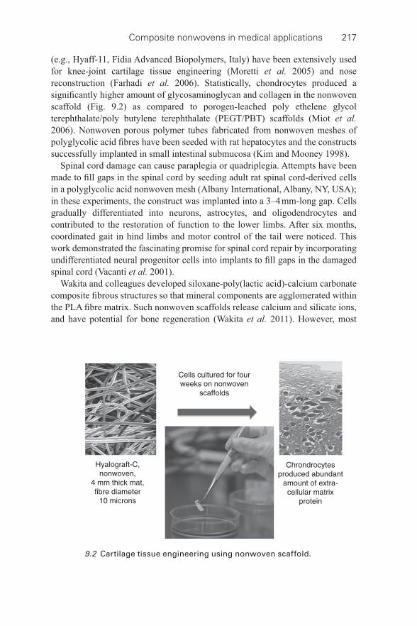
Composite nonwovens in medical applications 217
(e.g., Hyaff-11, Fidia Advanced Biopolymers, Italy) have been extensively used for knee- joint cartilage tissue engineering (Moretti et al. 2005) and nose reconstruction (Farhadi et al. 2006). Statistically, chondrocytes produced a signifi cantly higher amount of glycosaminoglycan and collagen in the nonwoven scaffold ( Fig. 9.2 ) as compared to porogen- leached poly ethelene glycol terephthalate/poly butylene terephthalate (PEGT/PBT) scaffolds (Miot et al. 2006). Nonwoven porous polymer tubes fabricated from nonwoven meshes of polyglycolic acid fi bres have been seeded with rat hepatocytes and the constructs successfully implanted in small intestinal submucosa (Kim and Mooney 1998).
Spinal cord damage can cause paraplegia or quadriplegia. Attempts have been made to fi ll gaps in the spinal cord by seeding adult rat spinal cord- derived cells in a polyglycolic acid nonwoven mesh (Albany International, Albany, NY, USA); in these experiments, the construct was implanted into a 3–4 mm- long gap. Cells gradually differentiated into neurons, astrocytes, and oligodendrocytes and contributed to the restoration of function to the lower limbs. After six months, coordinated gait in hind limbs and motor control of the tail were noticed. This work demonstrated the fascinating promise for spinal cord repair by incorporating undifferentiated neural progenitor cells into implants to fi ll gaps in the damaged spinal cord (Vacanti et al. 2001).
Wakita and colleagues developed siloxane- poly(lactic acid)-calcium carbonate composite fi brous structures so that mineral components are agglomerated within the PLA fi bre matrix. Such nonwoven scaffolds release calcium and silicate ions, and have potential for bone regeneration (Wakita et al. 2011). However, most
9.2 Cartilage tissue engineering using nonwoven scaffold.
218 Composite Nonwoven Materials
nonwoven scaffolds reported so far have poor compressive strength and are hence unsuitable for bone tissue engineering. For the purpose of bone regeneration, attempts have been made to develop fi bre- reinforced polymer foam. The reinforcing effect of fi bres within a matrix becomes effective when fi bres are uniformly distributed throughout the matrix, the degree of fi bre- polymer contact is maximized and fi bre–fi bre contact is kept at a minimum. Generally, this type of scaffold is made using a solvent- casting technique. Mandal et al. (2012) attempted to develop a silk- fi bre-reinforced scaffold to simulate the compressive modulus of bone. Interfacial bonding between the silk fi bre and the silk matrix resulted in an compressive modulus of 10 MPa in hydrated conditions. Such matrix stiffness and surface roughness support osteogenic differentiation of mesenchymal stem cells to prepare bone- like tissue (Mandal et al. 2012).
There is no successful clinical option available for patients suffering from end- stage liver disease. Bioartifi cial liver support systems based on hollow fi bre technology have undergone clinical trials and have been demonstrated to be promising (Watanabe et al. 1997). In this system, hepatocytes are placed inside a chambered cartridge. When patients’ blood is passed through, cells process toxins from the blood and synthesize proteins and metabolites. This plasma is then returned to the patient’s body. In such systems, oxygenated plasma fl ows through the fi bre capillary, but hepatocytes are attached in extracapillary spaces. As a result, the oxygen supply to the hepatocytes is inadequate because the oxygen- binding ability of plasma is less than one- tenth of that of whole blood. This limited oxygen supply leads to insuffi cient function of hepatocytes.
Li et al. (2006) used a roller pump in which polysulfone hollow fi bres were spirally wound with polytetrafl uoroethylene nonwoven fabric. Nonwoven fabric allowed attachment and aggregation of hepatocytes, and semipermeable membranes of hollow fi bres served as gas exchangers and immuno- protective barriers. Whole blood passed through the intra- luminal space of the hollow fi bres and was exposed to the hepatocytes for effective oxygen supply, CO 2 removal and exchange of metabolic waste and nutrients. Hence, the diffusion distance was reduced and mass exchange took place akin to that in the sinusoids of the liver parenchyma.
9.7 Hernia meshes
A hernia is a protrusion of a tissue through the wall of the cavity in which it is normally contained. Nonwoven meshes should be easy to use in both laparoscopic and open hernia repair. Fibrous capsule formation, cellular attachment and mesh contraction result in the recurrence of hernias in most patients. Woven polypropylene meshes frequently form adhesion and fi stula when transplanted intra- peritoneally. Polypropylene nonwoven fabric has been demonstrated to overcome such complications due to its microporous structure giving a high capacity for tissue in- growth and integration (Langenbach et al. 2003).
Composite nonwovens in medical applications 219
Raptis et al. (2011) implanted woven as well as nonwoven polypropylene fabrics into 12 pigs to compare ease of incorporation and removal by histology and adhesion formation 90 days after implantation. Intraperitoneally, woven polypropylene fabric became fully peritonealized, but generated thick and abundant adhesions. Interestingly, polypropylene nonwoven fabric became fully peritonealized and generated only very thin adhesions, and to a strikingly lesser extent. Woven meshes formed comparatively dense adhesions that could only be detached with greater diffi culty than with nonwoven meshes (Raptis et al. 2011).
Weyhe et al. (2006) and Dubova et al. (2007) investigated the infl ammatory response in rats during abdominal wall reconstruction using polypropylene fabrics, at different time points after surgery. One group of rats received heavy woven polypropylene meshes with macro- dimensional pores, and the other group of rats received light nonwoven fabrics with micro- dimensional pores. A more severe infl ammatory reaction was noticed in the group which received nonwoven fabrics. Interestingly, however, Dubova et al. (2007) noticed less intense fi brosis in the nonwoven fabric, with uniform tissue growth after 28 days, while Weyhe et al. (2006) reported a decline in the concentration of infl ammatory cells over time in both groups. Fibrous tissue formation took place in both types of hernia mesh after 45 days, with no statistical difference between the groups.
9.8 Filtration materials for medical applications
Red blood cell concentrates and platelet concentrates are commonly transfused to patients. It has been observed that the presence of white blood cells (leukocytes) in blood during transfusion may cause several adverse reactions, including recurrent febrile nonhemolytic transfusion reaction with high fever and vomiting, platelet refractoriness, graft versus host disease, and transmission of viruses (e.g. cytomegalovirus and HIV). The preferred method is therefore to reduce leukocyte- counts before storage of peripheral blood at the blood bank.
Kim et al. (2009) developed meltblown poly(butylene terephthalate) nonwoven and graft- polymerized acrylic acid onto it by oxygen plasma glow discharge treatment. They then immersed the nonwoven fabric in an aqueous solution containing high concentrations of phosphate and calcium ions to produce a thin layer of hydroxyapatite. This composite nonwoven was found to successfully remove 98.5% of leukocytes and recovered 99.5% of erythrocytes. This strategy seems promising compared to the standard procedure of removing cell populations by centrifugation.
Bone marrow- derived mesenchymal stem cells are regularly used for regenerative medicine strategies. Isolation of these stem cells from total marrow is usually conducted using a sucrose- based density gradient column, which is a time- consuming process. After screening 200 biomaterials, Ito et al. (2010) selected rayon–polyethylene nonwoven fabric for the development of a fi lter for the collection of mesenchymal stem cells from bone marrow hematopoietic
220 Composite Nonwoven Materials
mononuclear cells. Mesenchymal stem cells adhered tightly to highly hydrophilic and rough surfaces as compared to hydrophobic and smooth surfaces, resulting in a rapid and effi cient method of cell isolation fi ltration.
9.9 Incontinence products
Healthcare and hygiene products for incontinence tend to basically consist of an absorbent pad and skin contact layer and a transparent (waterproof) fi lm adhesive tape. Composite nonwoven based incontinence and hygiene products can be classifi ed as follows:
• Babycare products: baby nappies and baby wipes (dry or moisturized). • Feminine hygiene products: sanitary napkins, panty shields and liners. • Adult incontinence: adult nappies, nursing pads, disposable underwear,
bladder control pads.
These products are discussed in detail in Chapter 5 of this book.
9.10 Conclusion and future trends
Advances in the development of composite nonwovens for various medical applications are signifi cantly changing the lives of many people. However, the emergence of drug- resistant microbial strains demands more effi cient detection mechanisms for surgical drapings and masks and better anti- viral, anti- microbial strategies. The detection, prevention and killing of viruses and bacteria such as methicillin- resistant Staphylococcus aureus , hepatitis, SARS or H1N1, remain permanent challenges in the development of protection for healthcare workers.
Although signifi cant progress has already been made in research on nonwovens, structure–function relationships still need to be elucidated. Moreover, in order to face up to such challenging problems, researchers should not be afraid of blurring the boundaries of traditional textile technology. A multi- disciplinary approach is required to develop the next generation of products – for example, electronics- embedded nonwovens for effi cient detection of viral particles on a facemask – to improve understanding of the interaction of the nonwoven matrix with cells and the related cellular signalling process to induce organ regeneration. As boundaries between disciplines blur, multi- disciplinary research will become the norm rather than the exception, stimulating further growth in the nonwovens sector.
9.11 References
Carter , R. ( 1990 ) ‘ The journal of infection control nursing: ritual and risk ’, Nurs Times , 86 , 63 – 4 .
Cetinkaya , G. , Türkoğlu , H. , Arat , S. , Odaman , H. , Onur , M.A. , et al. ( 2007 ) ‘ LIF-immobilized nonwoven polyester fabrics for cultivation of murine embryonic stem cells ’, J Biomed Mater Res A , 81 , 911 – 19 .
Composite nonwovens in medical applications 221
Dineen , P. , and Drusin , L. ( 1973 ) ‘ Epidemics of postoperative wound infections associated with hair carriers ’, Lancet , 2 , 1157 – 9 .
Dubova , E.A. , Shchyogolev , A.I. , Chekmaryova , I.A. , Filatkina , N.V. , Chizhov , D.V. , and Yegiev , V.N. ( 2007 ) ‘ Morphological characteristics of tissue reaction in the zone of “Cousin” unwoven polypropylene endoprosthesis implantation ’, Bull Exp Biol Med , 143 , 656 – 61 .
Eisen , D.B. ( 2011 ) ‘ Surgeon’s garb and infection control: What’s the evidence? ’, J Am Acad Dermatol , 64 , 1 – 20 .
Farhadi , J. , Fulco , I. , Miot , S. , Wirz , D. , Haug , M. , et al. ( 2006 ) ‘ Precultivation of engineered human nasal cartilage enhances the mechanical properties relevant for use in facial reconstructive surgery ’, Ann Surg , 244 , 978 – 85 .
Ito , K. , Aoyama , T. , Fukiage , K. , Otsuka , S. , Furu , M. , et al. ( 2010 ) ‘ A novel method to isolate mesenchymal stem cells from bone marrow in a closed system using a device made by nonwoven fabric ’, Tissue Eng Part C Methods , 16 , 81 – 91 .
Jones , M. , and Jakeways , M. ( 1988 ) ‘ Theatre nursing: over- estimating overshoes ’, Nurs Times , 84 , 66 – 71 .
Kai , D. , Jin , G. , Prabhakaran , M.P. , and Ramakrishna , S. ( 2013 ) ‘ Electrospun synthetic and natural nanofi bers for regenerative medicine and stem cells ’, Biotechnol J , 8 , 59 – 72 .
Kim , B.S. , and Mooney , D.J. ( 1998 ), ‘ Development of biocompatible synthetic extracellular matrices for tissue engineering ’, Trends Biotechnol , 16 , 224 – 30 .
Kim , E.J. , Yeo , G. , Pai , C. , and Kang , I. ( 2009 ), ‘ Preparation of surface- modifi ed poly(butylene terephthalate) nonwovens and their application as leukocyte removal fi lters ’, J Biomed Mater Res, Part B: Appl Biomater , 90 , 849 – 56 .
Langenbach , M.R. , Schmidt , J. , and Zirngibl , H. ( 2003 ) ‘ Comparison of biomaterials in the early postoperative period. Polypropylene meshes in laparoscopic inguinal hernia repair ’, Surg Endosc , 17 , 1105 – 9 .
Lankester , B.J. , Bartlett , G.E. , Garneti , N. , Blom , A.W. , Bowker , K.E. , and Bannister , G.C. ( 2002 ) ‘ Direct measurement of bacterial penetration through surgical gowns: a new method ’, J Hosp Infect 2002 , 50 , 281 – 5 .
Leonas , K.K. , and Jinkins , R.S. ( 1997 ) ‘ The relationship of selected fabric characteristics and the barrier effectiveness of surgical gown fabrics ’, Am J Infect Control , 25 , 16 – 23 .
Li , L.J. , Du , W.B. , Zhang , Y.M. , Li , J. , Pan , X.P. , et al. ( 2006 ) ‘ Evaluation of a bioartifi cial liver based on a nonwoven fabric bioreactor with porcine hepatocytes in pigs ’, Journal of Hepatology , 44 , 317 – 324 .
Ma , T. , Li , Y. , Yang , S.T. , and Kniss , D.A. ( 2000 ) ‘ Effects of pore size in 3-d fi brous matrix on human trophoblast tissue development ’, Biotechnol Bioeng , 70 , 606 – 18 .
Mandal , B.B. , Grinberg , A. , Gil , E.S. , Panilaitis , B. , and Kaplan , D.K. ( 2012 ) ‘ High- strength silk protein scaffolds for bone repair ’, PNAS , 109 , 7699 – 704 .
Mangram , A.J. , Horan , T.C. , Pearson , M.L. , Silver , L.C. , and Jarvis , W.R. ( 1999 ) ‘ Guideline for prevention of surgical site infection, hospital infection control practices advisory committee ’, Infect Control Hosp Epidemiol , 20 , 250 – 78 .
McCullough , E.A. , and Schoenberger , L.K. ( 1991 ) ‘ Liquid barrier properties of nine surgical gown fabrics ’, INDA Journal of Nonwovens Research , 3 , 14 – 20 .
Miot , S. , Scandiucci de Freitas , P. , Wirz , D. , Daniels , A.U. , Sims , T.J. , et al. ( 2006 ) ‘ Cartilage tissue engineering by expanded goat articular chondrocytes ’, J Orthop Res , 24 , 1078 – 85 .
Moretti , M. , Wendt , D. , Dickinson , S.C. , Sims , T.J. , Hollander , A.P. , et al. ( 2005 ) ‘ Effects of in vitro preculture on in vivo development of human engineered cartilage in an ectopic model ’, Tissue Eng , 11 , 1421 – 8 .
222 Composite Nonwoven Materials
Murphy , G.F. , Orgill , D.P. , and Yannas , I.V. ( 1990 ) ‘ Partial dermal regeneration is induced by biodegradable collagen- glycosaminoglycan grafts ’, Lab Invest , 62 , 305 – 13 .
Raptis , D.A. , Vichova , B. , Breza , J. , Skipworth , J. , and Barker , S. ( 2011 ) ‘ A comparison of woven versus nonwoven polypropylene (PP) and expanded versus condensed polytetrafl uoroethylene (PTFE) on their intraperitoneal incorporation and adhesion formation ’, J Surg Res , 169 , 1 – 6 .
Shieh , S.J. , Terada , S. , and Vacanti , J.P. ( 2004 ) ‘ Tissue engineering auricular reconstruction: in vitro and in vivo studies ’, Biomaterials , 25 , 1545 – 57 .
Soliman , S. , Sant , S. , Nichol , J.W. , Khabiry , M. , Traversa , E. , and Khademhosseini , A. ( 2011 ) ‘ Controlling the porosity of fi brous scaffolds by modulating the fi ber diameter and packing density ’, J Biomed Mater Res A , 96 , 566 – 74 .
Tomasek , J.J. , Gabbiani , G. , Hinz , B. , Chaponnier , C. , and Brown , R.A. ( 2002 ) ‘ Myofi broblasts and mechano- regulation of connective tissue remodelling ’, Nat Rev Mol Cell Biol , 3 , 349 – 63 .
Vacanti , M.P. , Leonard , J.L. , Dore , B. , Bonassar , L.J. , Cao , Y. , et al. ( 2001 ) ‘ Tissue- engineered spinal cord ’, Transplant Proc , 33 , 592 – 8 .
Wakita , T. , Nakamura , J. , Ota , Y. , Obata , A. , Kasuga , T. , and Ban , S. ( 2011 ) ‘ Effect of preparation route on the degradation behavior and ion releasability of siloxane- poly(lactic acid)-vaterite hybrid nonwoven fabrics for guided bone regeneration ’, Dental Materials Journal , 30 , 232 – 8 .
Watanabe , F.D. , Mullon , C.J. , Hewitt , W.R. , Arkadopoulos , N. , Kahaku , E. , et al. ( 1997 ) ‘ Clinical experience with a bioartifi cial liver in the treatment of severe liver failure. A phase I clinical trial ’, Ann Surg , 225 , 484 – 9 .
Weyhe , D. , Schmitz , I. , Belyaev , O. , Grabs , R. , Müller , K.M. , et al. ( 2006 ) ‘ Experimental comparison of monofi le light and heavy polypropylene meshes: less weight does not mean less biological response ’, World J Surg , 30 , 1586 – 91 .
Yannas , I.V. ( 2013 ) ‘ Emerging rules for inducing organ regeneration ’, Biomaterials , 34 , 321 – 30 .
Zhang , X. , Reagan , M.R. , and Kaplan , D.L. ( 2009 ) ‘ Electrospun silk biomaterial scaffolds for regenerative medicine ’, Advanced Drug Delivery Reviews , 61 , 988 – 1006 .
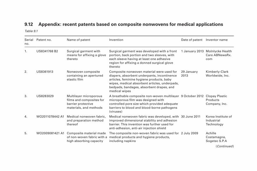
9.12 Appendix: recent patents based on composite nonwovens for medical applications
Table 9.1
Serial no.
Patent no. Name of patent Invention Date of patent Inventor name
1. US8341768 B2 Surgical garment with means for affi xing a glove thereto
Surgical garment was developed with a front portion, back portion and two sleeves, with each sleeve having at least one adhesive region for affi xing a donned surgical glove thereto
1 January 2013 Molnlycke Health Care ABNewsRx.com
2. US8361913 Nonwoven composite containing an apertured elastic fi lm
Composite nonwoven material were used for diapers, absorbent underpants, incontinence articles, feminine hygiene products, baby wipes, medical absorbent articles, underpads, bedpads, bandages, absorbent drapes, and medical wipes
29 January 2013
Kimberly-Clark Worldwide, Inc.
3. US8283029 Multilayer microporous fi lms and composites for barrier protective materials, and methods
A breathable composite non- woven multilayer microporous fi lm was designed with controlled pore size which provided adequate barriers to blood and blood- borne pathogens (viruses)
9 October 2012 Clopay Plastic Products Company, Inc.
4. WO2011078442 A1 Medical nonwoven fabric, and preparation method thereof
Medical nonwoven fabric was developed, with improved dimensional stability and adhesion barrier. This invention was further used for anti- adhesion, anti- air injection shield
30 June 2011 Korea Institute of Industrial Technology
5. WO2009081421 A1 Composite material made of non- woven fabric with a high absorbing capacity
The composite non- woven fabric was used for medical products and hygiene products, including napkins
2 July 2009 Achille Costamagna, Sogetec S.P.A
(Continued )
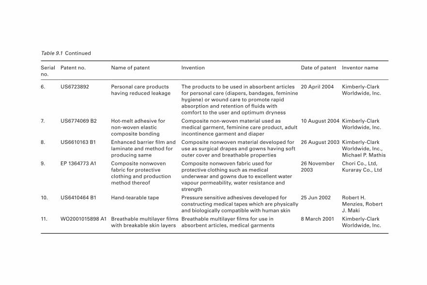
Serial no.
Patent no. Name of patent Invention Date of patent Inventor name
6. US6723892 Personal care products having reduced leakage
The products to be used in absorbent articles for personal care (diapers, bandages, feminine hygiene) or wound care to promote rapid absorption and retention of fl uids with comfort to the user and optimum dryness
20 April 2004 Kimberly-Clark Worldwide, Inc.
7. US6774069 B2 Hot- melt adhesive for non- woven elastic composite bonding
Composite non- woven material used as medical garment, feminine care product, adult incontinence garment and diaper
10 August 2004 Kimberly-Clark Worldwide, Inc.
8. US6610163 B1 Enhanced barrier fi lm and laminate and method for producing same
Composite nonwoven material developed for use as surgical drapes and gowns having soft outer cover and breathable properties
26 August 2003 Kimberly-Clark Worldwide, Inc., Michael P. Mathis
9. EP 1364773 A1 Composite nonwoven fabric for protective clothing and production method thereof
Composite nonwoven fabric used for protective clothing such as medical underwear and gowns due to excellent water vapour permeability, water resistance and strength
26 November 2003
Chori Co., Ltd, Kuraray Co., Ltd
10. US6410464 B1 Hand- tearable tape Pressure sensitive adhesives developed for constructing medical tapes which are physically and biologically compatible with human skin
25 Jun 2002 Robert H. Menzies, Robert J. Maki
11. WO2001015898 A1 Breathable multilayer fi lms with breakable skin layers
Breathable multilayer fi lms for use in absorbent articles, medical garments
8 March 2001 Kimberly-Clark Worldwide, Inc.
Table 9.1 Continued
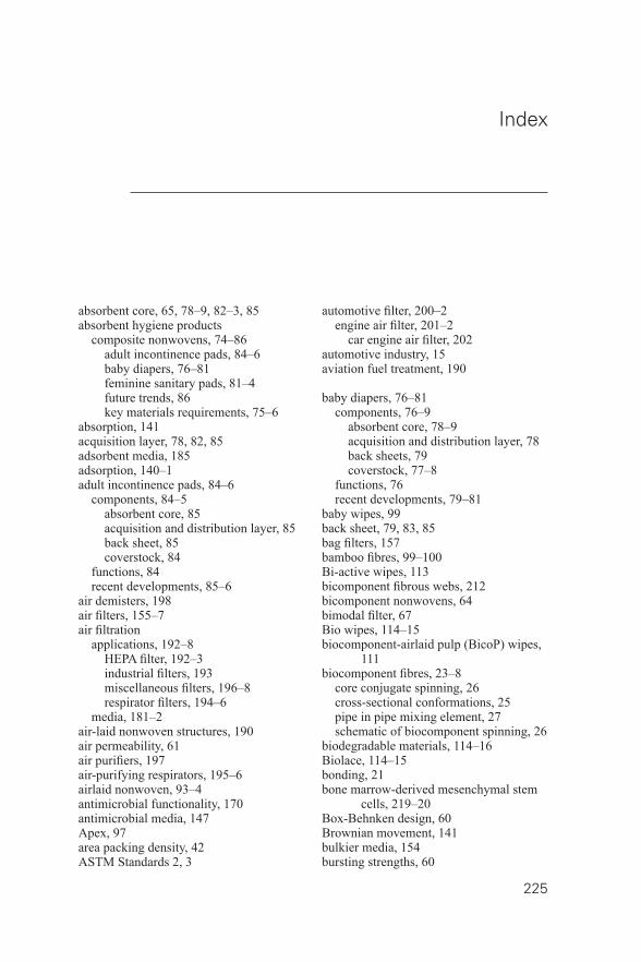
225
Index
absorbent core, 65, 78–9, 82–3, 85 absorbent hygiene products
composite nonwovens, 74–86 adult incontinence pads, 84–6 baby diapers, 76–81 feminine sanitary pads, 81–4 future trends, 86 key materials requirements, 75–6
absorption, 141 acquisition layer, 78, 82, 85 adsorbent media, 185 adsorption, 140–1 adult incontinence pads, 84–6
components, 84–5 absorbent core, 85 acquisition and distribution layer, 85 back sheet, 85 coverstock, 84
functions, 84 recent developments, 85–6
air demisters, 198 air fi lters, 155–7 air fi ltration
applications, 192–8 HEPA fi lter, 192–3 industrial fi lters, 193 miscellaneous fi lters, 196–8 respirator fi lters, 194–6
media, 181–2 air- laid nonwoven structures, 190 air permeability, 61 air purifi ers, 197 air- purifying respirators, 195–6 airlaid nonwoven, 93–4 antimicrobial functionality, 170 antimicrobial media, 147 Apex, 97 area packing density, 42 ASTM Standards 2, 3
automotive fi lter, 200–2 engine air fi lter, 201–2
car engine air fi lter, 202 automotive industry, 15 aviation fuel treatment, 190
baby diapers, 76–81 components, 76–9
absorbent core, 78–9 acquisition and distribution layer, 78 back sheets, 79 coverstock, 77–8
functions, 76 recent developments, 79–81
baby wipes, 99 back sheet, 79, 83, 85 bag fi lters, 157 bamboo fi bres, 99–100 Bi- active wipes, 113 bicomponent fi brous webs, 212 bicomponent nonwovens, 64 bimodal fi lter, 67 Bio wipes, 114–15 biocomponent- airlaid pulp (BicoP) wipes,
111 biocomponent fi bres, 23–8
core conjugate spinning, 26 cross- sectional conformations, 25 pipe in pipe mixing element, 27 schematic of biocomponent spinning, 26
biodegradable materials, 114–16 Biolace, 114–15 bonding, 21 bone marrow- derived mesenchymal stem
cells, 219–20 Box-Behnken design, 60 Brownian movement, 141 bulkier media, 154 bursting strengths, 60
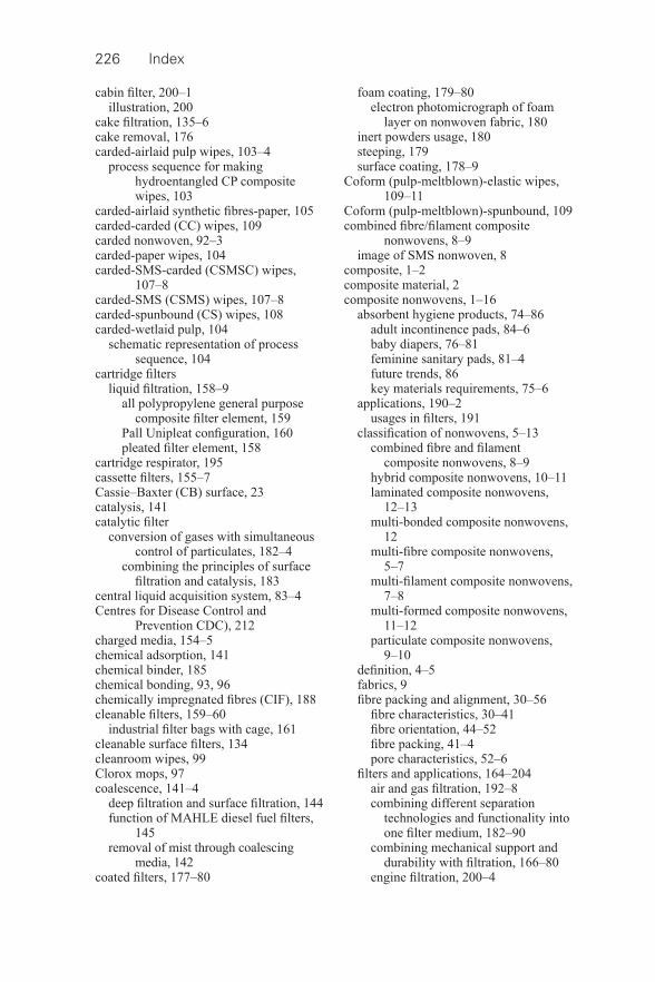
226 Index
cabin fi lter, 200–1 illustration, 200
cake fi ltration, 135–6 cake removal, 176 carded- airlaid pulp wipes, 103–4
process sequence for making hydroentangled CP composite wipes, 103
carded- airlaid synthetic fi bres- paper, 105 carded- carded (CC) wipes, 109 carded nonwoven, 92–3 carded- paper wipes, 104 carded-SMS-carded (CSMSC) wipes,
107–8 carded-SMS (CSMS) wipes, 107–8 carded- spunbound (CS) wipes, 108 carded- wetlaid pulp, 104
schematic representation of process sequence, 104
cartridge fi lters liquid fi ltration, 158–9
all polypropylene general purpose composite fi lter element, 159
Pall Unipleat confi guration, 160 pleated fi lter element, 158
cartridge respirator, 195 cassette fi lters, 155–7 Cassie–Baxter (CB) surface, 23 catalysis, 141 catalytic fi lter
conversion of gases with simultaneous control of particulates, 182–4
combining the principles of surface fi ltration and catalysis, 183
central liquid acquisition system, 83–4 Centres for Disease Control and
Prevention CDC), 212 charged media, 154–5 chemical adsorption, 141 chemical binder, 185 chemical bonding, 93, 96 chemically impregnated fi bres (CIF), 188 cleanable fi lters, 159–60
industrial fi lter bags with cage, 161 cleanable surface fi lters, 134 cleanroom wipes, 99 Clorox mops, 97 coalescence, 141–4
deep fi ltration and surface fi ltration, 144 function of MAHLE diesel fuel fi lters,
145 removal of mist through coalescing
media, 142 coated fi lters, 177–80
foam coating, 179–80 electron photomicrograph of foam
layer on nonwoven fabric, 180 inert powders usage, 180 steeping, 179 surface coating, 178–9
Coform (pulp- meltblown)-elastic wipes, 109–11
Coform (pulp- meltblown)-spunbound, 109 combined fi bre/fi lament composite
nonwovens, 8–9 image of SMS nonwoven, 8
composite, 1–2 composite material, 2 composite nonwovens, 1–16
absorbent hygiene products, 74–86 adult incontinence pads, 84–6 baby diapers, 76–81 feminine sanitary pads, 81–4 future trends, 86 key materials requirements, 75–6
applications, 190–2 usages in fi lters, 191
classifi cation of nonwovens, 5–13 combined fi bre and fi lament
composite nonwovens, 8–9 hybrid composite nonwovens, 10–11 laminated composite nonwovens,
12–13 multi- bonded composite nonwovens,
12 multi- fi bre composite nonwovens,
5–7 multi- fi lament composite nonwovens,
7–8 multi- formed composite nonwovens,
11–12 particulate composite nonwovens,
9–10 defi nition, 4–5 fabrics, 9 fi bre packing and alignment, 30–56
fi bre characteristics, 30–41 fi bre orientation, 44–52 fi bre packing, 41–4 pore characteristics, 52–6
fi lters and applications, 164–204 air and gas fi ltration, 192–8 combining different separation
technologies and functionality into one fi lter medium, 182–90
combining mechanical support and durability with fi ltration, 166–80
engine fi ltration, 200–4
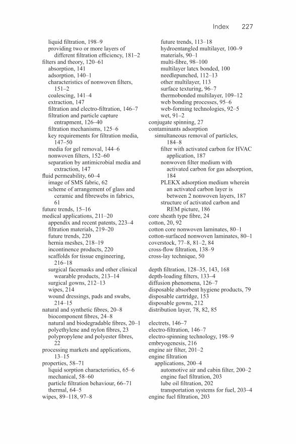
Index 227
liquid fi ltration, 198–9 providing two or more layers of
different fi ltration effi ciency, 181–2 fi lters and theory, 120–61
absorption, 141 adsorption, 140–1 characteristics of nonwoven fi lters,
151–2 coalescing, 141–4 extraction, 147 fi ltration and electro- fi ltration, 146–7 fi ltration and particle capture
entrapment, 126–40 fi ltration mechanisms, 125–6 key requirements for fi ltration media,
147–50 media for gel removal, 144–6 nonwoven fi lters, 152–60 separation by antimicrobial media and
extraction, 147 fl uid permeability, 60–4
image of SMS fabric, 62 scheme of arrangement of glass and
ceramic and fi brewebs in fabrics, 61
future trends, 15–16 medical applications, 211–20
appendix and recent patents, 223–4 fi ltration materials, 219–20 future trends, 220 hernia meshes, 218–19 incontinence products, 220 scaffolds for tissue engineering,
216–18 surgical facemasks and other clinical
wearable products, 213–14 surgical gowns, 212–13 wipes, 214 wound dressings, pads and swabs,
214–15 natural and synthetic fi bres, 20–8
biocomponent fi bres, 24–8 natural and biodegradable fi bres, 20–1 polyethylene and nylon fi bres, 23 polypropylene and polyester fi bres,
22 processing markets and applications,
13–15 properties, 58–71
liquid sorption characteristics, 65–6 mechanical, 58–60 particle fi ltration behaviour, 66–71 thermal, 64–5
wipes, 89–118, 97–8
future trends, 113–18 hydroentangled multilayer, 100–9 materials, 90–1 multi- fi bre, 98–100 multilayer latex bonded, 100 needlepunched, 112–13 other multilayer, 113 surface texturing, 96–7 thermobonded multilayer, 109–12 web bonding processes, 95–6 web- forming technologies, 92–5 wet, 91–2
conjugate spinning, 27 contaminants adsorption
simultaneous removal of particles, 184–8
fi lter with activated carbon for HVAC application, 187
nonwoven fi lter medium with activated carbon for gas adsorption, 184
PLEKX adsorption medium wherein an activated carbon layer is between 2 nonwoven layers, 187
structure of activated carbon and REM picture, 186
core sheath type fi bre, 24 cotton, 20, 92 cotton core nonwoven laminates, 80–1 cotton- surfaced nonwoven laminates, 80–1 coverstock, 77–8, 81–2, 84 cross- fl ow fi ltration, 138–9 cross- lay technique, 50
depth fi ltration, 128–35, 143, 168 depth- loading fi lters, 133–4 diffusion phenomena, 126–7 disposable absorbent hygiene products, 79 disposable cartridge, 153 disposable gowns, 212 distribution layer, 78, 82, 85
electrets, 146–7 electro- fi ltration, 146–7 electro- spinning technology, 198–9 embryogenesis, 216 engine air fi lter, 201–2 engine fi ltration
applications, 200–4 automotive air and cabin fi lter, 200–2 engine fuel fi ltration, 203 lube oil fi ltration, 202 transportation systems for fuel, 203–4
engine fuel fi ltration, 203
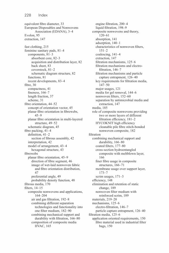
228 Index
equivalent fi bre diameter, 33 European Disposables and Nonwovens
Association (EDANA), 3–4 Evolon, 95 extraction, 147
fast clothing, 215 feminine sanitary pads, 81–4
components, 81–3 absorbent core, 82–3 acquisition and distribution layer, 82 back sheet, 83 coverstock, 81–2 schematic diagram structure, 82
functions, 81 recent developments, 83–4
fi bre, 30 compactness, 41 fi neness, 166–7 length fraction, 37 scheme, 31
fi bre orientation, 44–52 concept of orientation vector, 45 planar fi bre orientation in fi brewebs,
45–9 planar fi bre orientation in multi- layered
structure, 49–52 schematic diagram, 45
fi bre packing, 41–4 defi nition, 41–2
section of fi brous assembly, 42 interpretation, 42 model of arrangement, 43–4
hexagonal structure, 43 fi brewebs
planar fi bre orientation, 45–9 direction of fi bre segment, 46 image of wet- laid nonwoven fabric
and fi bre orientation distribution, 47
preferential angle, 49 probability density function, 48
fi brous media, 170 fi lters, 14–15
composite nonwovens and applications, 164–204
air and gas fi ltration, 192–8 combining different separation
technologies and functionality into one fi lter medium, 182–90
combining mechanical support and durability with fi ltration, 166–80
composition of composite media HVAC, 165
engine fi ltration, 200–4 liquid fi ltration, 198–9
composite nonwovens and theory, 120–61
absorption, 141 adsorption, 140–1 characteristics of nonwoven fi lters,
151–2 coalescing, 141–4 extraction, 147 fi ltration mechanisms, 125–6 fi ltration mechanisms and electro- fi ltration, 146–7
fi ltration mechanisms and particle capture entrapment, 126–40
key requirements for fi ltration media, 147–50
major usages, 121 media for gel removal, 144–6 nonwoven fi lters, 152–60 separation by antimicrobial media and
extraction, 147 media, 185 role of composite nonwovens providing
two or more layers of different fi ltration effi ciency, 181–2
HYCOKNIT high effi ciency cleanable pile fi bre stitch- bonded nonwoven composite, 182
fi ltration combining mechanical support and
durability, 166–80 coated fi lters, 177–80 cross- section hydroentangled
composite with meltblown layer, 166
fi ner fi bre usage in composite structures, 166–71
membrane usage over support layer, 173–7
scrim usages, 171–3 effi ciency, 148 elimination and retention of static
change, 189 nonwoven fi lter medium with
reinforced scrim, 189 materials, 219–20 mechanisms, 125–6
electro- fi ltration, 146–7 particle capture entrapment, 126–40
fi ltration media, 125–6 application oriented requirements, 150
fi bre material used in industrial fi lter bags, 150
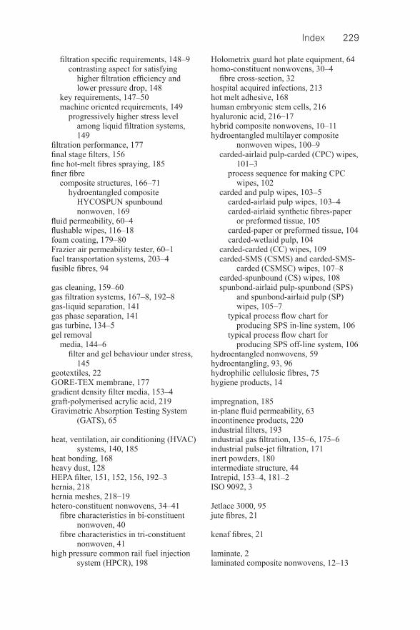
Index 229
fi ltration specifi c requirements, 148–9 contrasting aspect for satisfying
higher fi ltration effi ciency and lower pressure drop, 148
key requirements, 147–50 machine oriented requirements, 149
progressively higher stress level among liquid fi ltration systems, 149
fi ltration performance, 177 fi nal stage fi lters, 156 fi ne hot- melt fi bres spraying, 185 fi ner fi bre
composite structures, 166–71 hydroentangled composite
HYCOSPUN spunbound nonwoven, 169
fl uid permeability, 60–4 fl ushable wipes, 116–18 foam coating, 179–80 Frazier air permeability tester, 60–1 fuel transportation systems, 203–4 fusible fi bres, 94
gas cleaning, 159–60 gas fi ltration systems, 167–8, 192–8 gas- liquid separation, 141 gas phase separation, 141 gas turbine, 134–5 gel removal
media, 144–6 fi lter and gel behaviour under stress,
145 geotextiles, 22 GORE-TEX membrane, 177 gradient density fi lter media, 153–4 graft- polymerised acrylic acid, 219 Gravimetric Absorption Testing System
(GATS), 65
heat, ventilation, air conditioning (HVAC) systems, 140, 185
heat bonding, 168 heavy dust, 128 HEPA fi lter, 151, 152, 156, 192–3 hernia, 218 hernia meshes, 218–19 hetero- constituent nonwovens, 34–41
fi bre characteristics in bi- constituent nonwoven, 40
fi bre characteristics in tri- constituent nonwoven, 41
high pressure common rail fuel injection system (HPCR), 198
Holometrix guard hot plate equipment, 64 homo- constituent nonwovens, 30–4
fi bre cross- section, 32 hospital acquired infections, 213 hot melt adhesive, 168 human embryonic stem cells, 216 hyaluronic acid, 216–17 hybrid composite nonwovens, 10–11 hydroentangled multilayer composite
nonwoven wipes, 100–9 carded- airlaid pulp- carded (CPC) wipes,
101–3 process sequence for making CPC
wipes, 102 carded and pulp wipes, 103–5
carded- airlaid pulp wipes, 103–4 carded- airlaid synthetic fi bres- paper
or preformed tissue, 105 carded- paper or preformed tissue, 104 carded- wetlaid pulp, 104
carded- carded (CC) wipes, 109 carded-SMS (CSMS) and carded-SMS-
carded (CSMSC) wipes, 107–8 carded- spunbound (CS) wipes, 108 spunbond- airlaid pulp- spunbond (SPS)
and spunbond- airlaid pulp (SP) wipes, 105–7
typical process fl ow chart for producing SPS in- line system, 106
typical process fl ow chart for producing SPS off- line system, 106
hydroentangled nonwovens, 59 hydroentangling, 93, 96 hydrophilic cellulosic fi bres, 75 hygiene products, 14
impregnation, 185 in- plane fl uid permeability, 63 incontinence products, 220 industrial fi lters, 193 industrial gas fi ltration, 135–6, 175–6 industrial pulse- jet fi ltration, 171 inert powders, 180 intermediate structure, 44 Intrepid, 153–4, 181–2 ISO 9092, 3
Jetlace 3000, 95 jute fi bres, 21
kenaf fi bres, 21
laminate, 2 laminated composite nonwovens, 12–13
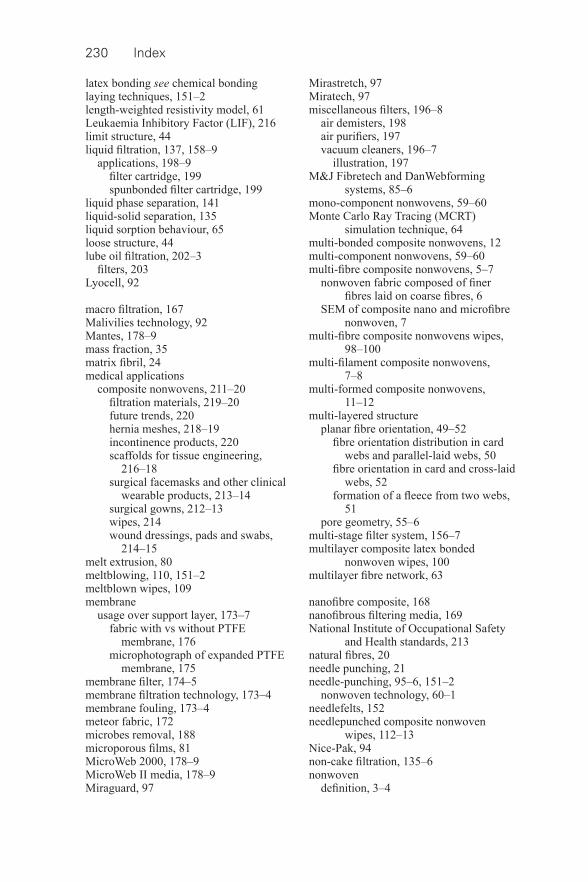
230 Index
latex bonding see chemical bonding laying techniques, 151–2 length- weighted resistivity model, 61 Leukaemia Inhibitory Factor (LIF), 216 limit structure, 44 liquid fi ltration, 137, 158–9
applications, 198–9 fi lter cartridge, 199 spunbonded fi lter cartridge, 199
liquid phase separation, 141 liquid- solid separation, 135 liquid sorption behaviour, 65 loose structure, 44 lube oil fi ltration, 202–3
fi lters, 203 Lyocell, 92
macro fi ltration, 167 Malivilies technology, 92 Mantes, 178–9 mass fraction, 35 matrix fi bril, 24 medical applications
composite nonwovens, 211–20 fi ltration materials, 219–20 future trends, 220 hernia meshes, 218–19 incontinence products, 220 scaffolds for tissue engineering,
216–18 surgical facemasks and other clinical
wearable products, 213–14 surgical gowns, 212–13 wipes, 214 wound dressings, pads and swabs,
214–15 melt extrusion, 80 meltblowing, 110, 151–2 meltblown wipes, 109 membrane
usage over support layer, 173–7 fabric with vs without PTFE
membrane, 176 microphotograph of expanded PTFE
membrane, 175 membrane fi lter, 174–5 membrane fi ltration technology, 173–4 membrane fouling, 173–4 meteor fabric, 172 microbes removal, 188 microporous fi lms, 81 MicroWeb 2000, 178–9 MicroWeb II media, 178–9 Miraguard, 97
Mirastretch, 97 Miratech, 97 miscellaneous fi lters, 196–8
air demisters, 198 air purifi ers, 197 vacuum cleaners, 196–7
illustration, 197 M&J Fibretech and DanWebforming
systems, 85–6 mono- component nonwovens, 59–60 Monte Carlo Ray Tracing (MCRT)
simulation technique, 64 multi- bonded composite nonwovens, 12 multi- component nonwovens, 59–60 multi- fi bre composite nonwovens, 5–7
nonwoven fabric composed of fi ner fi bres laid on coarse fi bres, 6
SEM of composite nano and microfi bre nonwoven, 7
multi- fi bre composite nonwovens wipes, 98–100
multi- fi lament composite nonwovens, 7–8
multi- formed composite nonwovens, 11–12
multi- layered structure planar fi bre orientation, 49–52
fi bre orientation distribution in card webs and parallel- laid webs, 50
fi bre orientation in card and cross- laid webs, 52
formation of a fl eece from two webs, 51
pore geometry, 55–6 multi- stage fi lter system, 156–7 multilayer composite latex bonded
nonwoven wipes, 100 multilayer fi bre network, 63
nanofi bre composite, 168 nanofi brous fi ltering media, 169 National Institute of Occupational Safety
and Health standards, 213 natural fi bres, 20 needle punching, 21 needle- punching, 95–6, 151–2
nonwoven technology, 60–1 needlefelts, 152 needlepunched composite nonwoven
wipes, 112–13 Nice-Pak, 94 non- cake fi ltration, 135–6 nonwoven
defi nition, 3–4
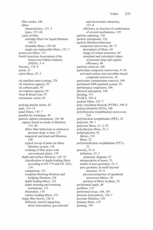
Index 231
fi lter media, 140 fi lters
characteristics, 151–2 types, 152–60
types of fi lter cartridge fi lters for liquid fi ltration,
158–9 cleanable fi lters, 159–60 single- use replaceable fi lters, 152–7
nonwoven fabric, 151 North American Association of the
Nonwoven Fabrics Industry (INDA), 3–4
Novates, 178–9 nylon, 23 nylon fi bres, 22–3
oil- repellent nano- coating, 170 oil retention capacity, 95 oil sorbent pads, 95 oil sorption capacity, 95 Oran-B Brush-Ups, 97 orientation vector, 45
packing density factor, 42 pads, 214–15 panel fi lters, 155–7 parallel- lay technique, 49 particle capture entrapment, 126–40
capture based on mode of fi ltration, 135–40
fabric fi lter behaviour in relation to pressure drop vs time, 137
tangential and dead- end fi ltration, 140
typical set- up of pulse jet fabric fi ltration system, 136
working of fi lter press with conventional plates, 139
depth and surface fi ltration, 128–35 classifi cation of depth- loading fi lters
according to EN 779 and EN 1822, 134
comparison, 131 complete blocking fi ltration and
bridging fi ltration, 130 depth loading fi lters, 132 depth straining and retaining
mechanism, 131 illustration, 130 surface loading fi lters, 133
single fi bre theory, 126–8 diffusion, inertial impaction,
direct interception, gravitational
and electrostatic attraction, 127–8
effi ciency as function of combination of several mechanisms, 129
particle capturing, 126 particle entrapment, 126 particle fi ltration behaviour
composite nonwovens, 66–71 description of fi lters, 68 image of virtual structures, 69 simulated and calculated values
of pressure drop and capture effi ciency, 68
particles removal, 188 particulate composite nonwovens, 9–10
activated carbon and microfi bre based composite nonwoven, 10
particulate contaminants removal, 190 perfobond 3000 spunlaid system, 95 performance respirators, 196 physical adsorption, 140 pleating, 153 PLEKX, 185–6 pockets fi lters, 155–7 poly- vinylidene fl uoride (PVDF), 198–9 polyacrylonitrile (PAN), 188 poly(butylene terephthalate) nonwoven,
219 polybutylene terephthalate (PBT), 22 polyester, 90–1 polyester fi bres, 21–2, 92 polyethylene fi bres, 22–3 polypropylene, 92
fabrics, 219 fi bres, 22
polytrimethylene terephthalate (PTT), 22
porosity, 52–6 defi nition, 52–3
schematic diagram, 53 interpretation of pores, 53 model of pore geometry, 53–5 pore geometry in multi- layered
structure, 55–6 physical properties of spunbond
nonwoven fabrics, 56 position of fi bres in plane, 55
preferential angle, 48 prefi lters, 153 preformed tissue, 104, 105 pressure drop pattern, 136–7 pressure fi ltration, 138 primary fi lters, 155 printing, 185
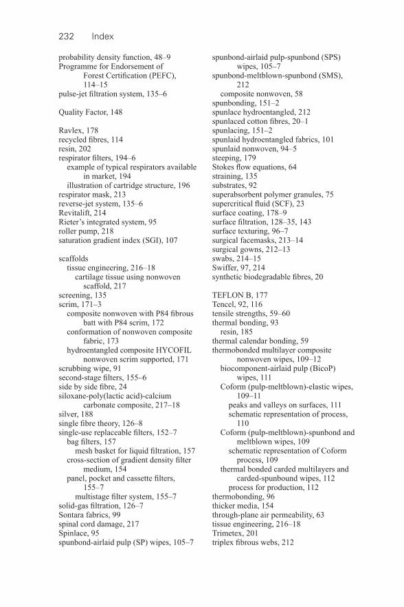
232 Index
probability density function, 48–9 Programme for Endorsement of
Forest Certifi cation (PEFC), 114–15
pulse- jet fi ltration system, 135–6
Quality Factor, 148
Ravlex, 178 recycled fi bres, 114 resin, 202 respirator fi lters, 194–6
example of typical respirators available in market, 194
illustration of cartridge structure, 196 respirator mask, 213 reverse- jet system, 135–6 Revitalift, 214 Rieter’s integrated system, 95 roller pump, 218 saturation gradient index (SGI), 107
scaffolds tissue engineering, 216–18
cartilage tissue using nonwoven scaffold, 217
screening, 135 scrim, 171–3
composite nonwoven with P84 fi brous batt with P84 scrim, 172
conformation of nonwoven composite fabric, 173
hydroentangled composite HYCOFIL nonwoven scrim supported, 171
scrubbing wipe, 91 second- stage fi lters, 155–6 side by side fi bre, 24 siloxane- poly(lactic acid)-calcium
carbonate composite, 217–18 silver, 188 single fi bre theory, 126–8 single- use replaceable fi lters, 152–7
bag fi lters, 157 mesh basket for liquid fi ltration, 157
cross- section of gradient density fi lter medium, 154
panel, pocket and cassette fi lters, 155–7
multistage fi lter system, 155–7 solid- gas fi ltration, 126–7 Sontara fabrics, 99 spinal cord damage, 217 Spinlace, 95 spunbond- airlaid pulp (SP) wipes, 105–7
spunbond- airlaid pulp- spunbond (SPS) wipes, 105–7
spunbond- meltblown- spunbond (SMS), 212
composite nonwoven, 58 spunbonding, 151–2 spunlace hydroentangled, 212 spunlaced cotton fi bres, 20–1 spunlacing, 151–2 spunlaid hydroentangled fabrics, 101 spunlaid nonwoven, 94–5 steeping, 179 Stokes fl ow equations, 64 straining, 135 substrates, 92 superabsorbent polymer granules, 75 supercritical fl uid (SCF), 23 surface coating, 178–9 surface fi ltration, 128–35, 143 surface texturing, 96–7 surgical facemasks, 213–14 surgical gowns, 212–13 swabs, 214–15 Swiffer, 97, 214 synthetic biodegradable fi bres, 20
TEFLON B, 177 Tencel, 92, 116 tensile strengths, 59–60 thermal bonding, 93
resin, 185 thermal calendar bonding, 59 thermobonded multilayer composite
nonwoven wipes, 109–12 biocomponent- airlaid pulp (BicoP)
wipes, 111 Coform (pulp- meltblown)-elastic wipes,
109–11 peaks and valleys on surfaces, 111 schematic representation of process,
110 Coform (pulp- meltblown)-spunbond and
meltblown wipes, 109 schematic representation of Coform
process, 109 thermal bonded carded multilayers and
carded- spunbound wipes, 112 process for production, 112
thermobonding, 96 thicker media, 154 through- plane air permeability, 63 tissue engineering, 216–18 Trimetex, 201 triplex fi brous webs, 212
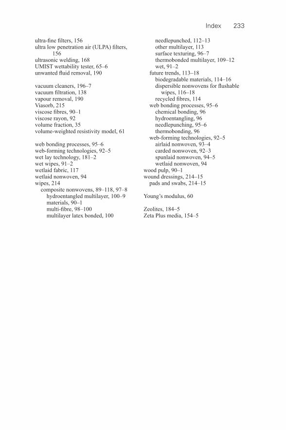
Index 233
ultra- fi ne fi lters, 156 ultra low penetration air (ULPA) fi lters,
156 ultrasonic welding, 168 UMIST wettability tester, 65–6 unwanted fl uid removal, 190
vacuum cleaners, 196–7 vacuum fi ltration, 138 vapour removal, 190 Viasorb, 215 viscose fi bres, 90–1 viscose rayon, 92 volume fraction, 35 volume- weighted resistivity model, 61
web bonding processes, 95–6 web- forming technologies, 92–5 wet lay technology, 181–2 wet wipes, 91–2 wetlaid fabric, 117 wetlaid nonwoven, 94 wipes, 214
composite nonwovens, 89–118, 97–8 hydroentangled multilayer, 100–9 materials, 90–1 multi- fi bre, 98–100 multilayer latex bonded, 100
needlepunched, 112–13 other multilayer, 113 surface texturing, 96–7 thermobonded multilayer, 109–12 wet, 91–2
future trends, 113–18 biodegradable materials, 114–16 dispersible nonwovens for fl ushable
wipes, 116–18 recycled fi bres, 114
web bonding processes, 95–6 chemical bonding, 96 hydroentangling, 96 needlepunching, 95–6 thermobonding, 96
web- forming technologies, 92–5 airlaid nonwoven, 93–4 carded nonwoven, 92–3 spunlaid nonwoven, 94–5 wetlaid nonwoven, 94
wood pulp, 90–1 wound dressings, 214–15
pads and swabs, 214–15
Young’s modulus, 60
Zeolites, 184–5 Zeta Plus media, 154–5

This page intentionally left blank