Embed Size (px)
Citation preview
Composite scaffolds for osteochondral repair obtained by combination of additive manufacturing, leaching processes and hMSC-CM functionalization
Andrés Díaz Lantada a,⁎, Hernán Alarcón Iniesta b, Josefa Predestinación García-Ruíz b
a Product Development Laboratory, Mechanical Engineering & Manufacturing Department, Universidad Politécnica de Madrid (UPM), c/José Gutiérrez Abascal 2, 28006 Madrid, Spain b Departamento de Biología Molecular, Universidad Autónoma de Madrid, 28049, Cantoblanco, Madrid, Spain
Keywords:
Tissue engineering Scaffolds for tissue repair Osteochondral repair Rapid prototyping Additive manufacture Computer-aided design & engineering
A b s t r a c t
Articular repair is a relevant and challenging area for the emerging fields of tissue engineering and biofabrication. The need of significant gradients of properties, for the promotion of osteochondral repair, has led to the develop ment of several families of composite biomaterials and scaffolds, using different effective approaches, although a perfect solution has not yet been found. In this study we present the design, modeling, rapid manufacturing and in vitro testing of a composite scaffold aimed at osteochondral repair. The presented composite scaffold stands out for having a functional gradient of density and stiffness in the bony phase, obtained in titanium by means of computer aided design combined with additive manufacture using selective laser sintering. The chondral phase is obtained by sugar leaching, using a PDMS matrix and sugar as porogen, and is joined to the bony phase during the polymerization of PDMS, therefore avoiding the use of supporting adhesives or additional intermediate layers. The mechanical performance of the construct is biomimetic and the stiffness values of the bony and chondral phases can be tuned to the desired applications, by means of controlled modifications of different parameters. A human mesenchymal stem cell (h MSC) conditioned medium (CM) is used for improving scaffold response. Cell culture results provide relevant information regarding the viability of the composite scaffolds used.
1. Introduction
Tissue engineering is based on the combination of biological, physical and engineering knowledge to promote the artificial development of improved replacements for tissues and organs linked to surgical repair strategies. A very relevant component, involved in tissue engineering processes, is the extra cellular matrix (ECM) or tissue engineering scaffold which serves as the framework for cell growth, aggregation, phenotype expression and final tissue development [1]. According to biomimetic design principles, the biomaterials used as scaffolds should be porous, so as to allow cell migration during the colonization process, as well as the transport of nutrients and waste to and from cells. Such biomaterial constructs also have to be resistant enough to withstand mechanical demands, especially if final implantation is desired. In addition, as cells are capable of feeling their microenvironment and of responding to the substrate texture upon which they lie, by changing their overall morphology, cytoskeleton configuration, and intra and extracellular signaling, an increasing number of studies are focusing on
* Corresponding author. E-mail address: [email protected] (A. Díaz Lantada). URL: http://www.upm.es (A. Díaz Lantada).
advanced design and manufacturing technologies, so as to generate and modify the structures and surfaces of biomaterial. Aspects such as porosity, pore distribution and size or surface micro and nano textures promote cell adherence, migration and proliferation within the scaffold, for subsequent gene expression and differentiation into relevant cell types. Hence, both tissue progenitor cells and the extra cellular matrices play a fundamental role in tissue engineering strate gies. The controlled design and fabrication of biomaterials used as scaffold structures are becoming increasingly important for regenerative medicine [2 4].
Most processes for manufacturing micro porous structures for tissue engineering [5] involve a combination of materials in some step of the process and a final phase separation or leaching process, for obtaining a solid part with distributed small pores. Among most extended pro cesses, gas assisted injection molding is an industrial method based on injecting a molten resin or thermoplastic into a mold cavity and then applying a quantity of pressurized gas into the resin, so as to help to fill out the mold cavity and to create hollows and pores in the poly mer. The incorporation of foaming agents as additives to polymers also allows the manufacture of polymeric parts with pores. In many strategies including tissue strategies, to obtain 3D porous structures is absolutely required to irrigate the tissue and maintain an adequate
liquid dynamics. The use of porogens is also commonplace; normally,the process involves mixing a liquid prepolymer with solid particles(typically wax, sugar, salt…). Once polymerization is produced,normally by UV exposure or by heating, a solid structure, formed by apolymeric network with dispersed particles, is obtained. Final porousstructure is obtained by dissolving such disperse particles in water,other solvents or by heating. The use of prepolymer water emulsionsis also typical for obtaining a polymerizable mixture that after thermalor UV based polymerization provides a polymeric network with poresaccording to initial water content (i.e. polyHIPEs).
Main alternatives, for improving the control of scaffolds' pore sizeand distribution, from the design stage, is the use of micro additivemanufacturing technologies (AMT), normally working on layer bylayer processes, following the geometries obtained with the help ofcomputer aided designs [6 7]. Electro spinning can be also adapted to“layer by layer” fabrication and used for obtaining 3D porous structures[8], even though the process is not as repetitive as the use ofmicro AMT.The progressive increase in the precision of additive manufacturingtechnologies, together with their improved versatility thanks to acontinuously increasing set of materials available for layer by layerprocessing, is greatly promoting applications linked to micro andeven nano manufacturing of complex 3D geometries for very innovative medical solutions in several fields [5].
Scaffolds with design controlled structures have been obtained bymeans of rapid prototyping technologies including: selective lasersintering (SLS) [9], layered hydrospinning [10], laser stereolithography(SLA) [11], digital light projection (DLP) [12] or two photon polymerization (2PP) [13], and different materials including hydrogels [14],gelatin [7], titanium alloys [15 16], (bio)photopolymers [17] andceramics [18]. However in vitro validation of rapid prototyped scaffoldsis not commonplace, as most combinations of processes and materialsdo not provide adequate biomaterials and in many cases generatetoxic components. Nevertheless some highly interesting research hasalready been published, including in vitro validation and systematictoxicity assessment [19 20]. Advances in the field of biopolymers[19 21] together with the possibilities provided by thin coatings [11],are bringing newpossibilities to this area, although access to suchmaterials and technologies is not always easy, as some of them are currentlyunder development or only available in large research centers.
In any case, it seems clear that a universal methodology for tissueengineering scaffold development is not yet available, first of all dueto the complexity of biological materials and systems, but also due toall the possible design resources, manufacturing technologies andrelated materials available, whose results have not been systematicallycompared. For instance, additive manufacturing technologies allowprecise control of final geometries from the design stage; howeversuch designs are normally obtained by combining Euclidean based(simple) geometries and final result does not mimic adequately thecomplexity of biomaterials. On the other hand, scaffolds obtained byphase separation and more “traditional” processes typically lead tomore biomimetic sponges, even though their final outer form andrepeatability are more difficult to control, than using computer aidedstrategies linked to rapid prototyping using additive processes.
Therefore, further research is needed to address the advantages ofcombining different technologies [22] for manufacturing enhanced,even personalized, scaffolds for tissue engineering studies and extracellular matrices with global (outer) geometries defined as implantsfor tissue repair. In addition, increasing data shows that progenitorcell niche formation is absolutely needed for tissue development andrepair [23]. Indeed, the niche composition and 3 D structure play animportant role in stem cell state and fate. The niche is created by thespecific combination of trophic factors produced by progenitor cells tomaintain the capability for tissue repair and regeneration and by aspecific extracellular matrix. Recent studies have helped to highlightthe extreme relevance of the incorporation of adequate growthfactors, within the scaffold, for promoting biological regulation, cell
differentiation, angiogenesis and final tissue viability [24 26]. Suchinclusion of biochemical effects, derived from the incorporation ofgrowth factors, adds additional uncertainties to the already complexto understand interactions between scaffolds' structure, morphologyandmechanical properties. Consequently, studies addressing the synergies between ECMs and growth factors and their impact on tissueviability are needed, in the quest for a general methodology for tissueengineering scaffold development.
The aforementioned tissue engineering challenges are even greaterin applications aimed at articular repair, where several types of tissues(bones, cartilages, ligaments, tendons…) must be replaced, if possibleusing a single multifunctional scaffold capable of promoting cell adhesion, growth, migration and differentiation into different types of tissues. The need of relevant gradients of properties for the promotion ofosteochondral repair has led to the development of composite scaffoldsusing different approaches previously reviewed [27,28]. Typicalmethods for the manufacture of scaffolds with functional gradients ofproperties include: the use of embedded (nano ) fibers and textileswithin polymeric matrixes [27,28,29], the combination of rigid latticestructures with cell carrying hydrogels [27,28,30], the use of multilayered constructs [31,32] (normally requiring adhesiveswithin layers),and computer aided tissue engineering constructs [33]. Among themost promising approaches, towards stable and effective compositescaffolds, it is important to note the combination of: a) phase separationor leaching processes, normally for obtaining the soft chondral phase,with b) computer aided rapid prototyping technologies based on additivemanufacturing, usually formanufacturing the rigid bonyphase [34].In spite of the very positive results shown bymetallic rapid prototypedprostheses and scaffolds for bone repair [35], most successful compositescaffolds for osteochondral repair are based on polymer ceramic composites [31,34,36], polymer polymer composites [37], ceramic ceramiccomposites [38], ceramic metal composites [39] and metal metalcomposites [40]. Interestingly, metal polymer composites, whichcould benefit from the stiffness of metals for the bony phase and fromthe elasticity of polymers for the chondral phase are not so common.
In this study we present the design, modeling, rapid manufacturingand in vitro testing of a composite scaffold aimed at osteochondralrepair. The presented composite scaffold stands out for having a functional gradient of density and stiffness in the bony phase, which isobtained in titanium by means of computer aided design combinedwith additive manufacture using selective laser sintering. The chondralphase is achieved by sugar leaching, using a PDMS matrix and sugar asporogen, and is joined to the bony phase during the polymerization ofPDMS, therefore avoiding the use of supporting adhesives or additionalintermediate layers. The mechanical performance of the construct isbiomimetic and the stiffness values of the bony and chondral phasescan be tuned to the desired applications, by means of controlled modifications of the computer aided designs, of the materials used, of therate of porogen employed, among other options that promote the versatility of the proposed approach. Cell culture results, carried out usingh MSCs with the help of growth factors generated by the own progenitor stem cells, provide relevant information regarding the viability ofthe composite scaffolds used and help us to plan forthcoming researchactivities. The following section details the materials and methodsused, before describing and analyzingmain results andproposing futuresteps towards the concept of the universal scaffold for osteochondralrepair.
2. Materials and methods
2.1. Computer aided design of functionally graded lattice andporous structures
Computer aided design of the different geometries was carriedout with the help of NX 8.5 (Siemens PLM Solutions), mainly usingcombinations of parametric and matrix based features and Boolean
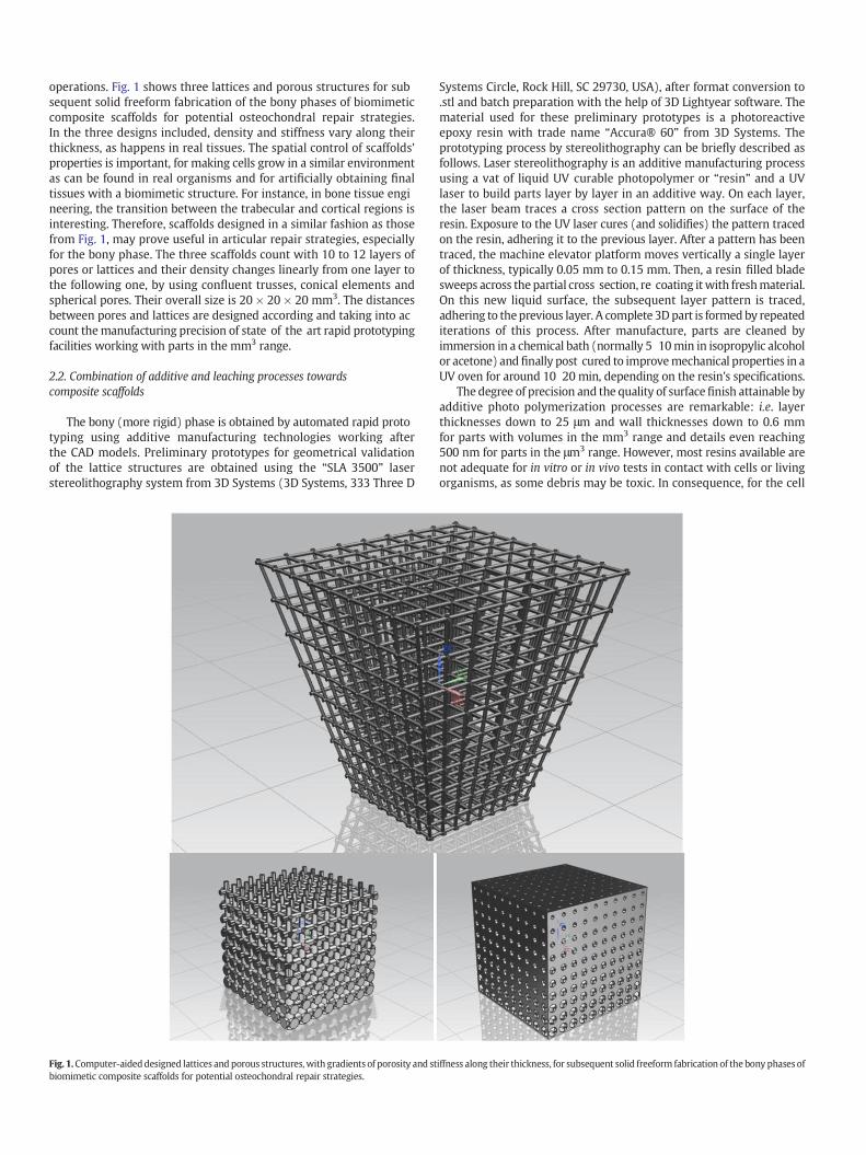
operations. Fig. 1 shows three lattices and porous structures for subsequent solid freeform fabrication of the bony phases of biomimeticcomposite scaffolds for potential osteochondral repair strategies.In the three designs included, density and stiffness vary along theirthickness, as happens in real tissues. The spatial control of scaffolds'properties is important, for making cells grow in a similar environmentas can be found in real organisms and for artificially obtaining finaltissues with a biomimetic structure. For instance, in bone tissue engineering, the transition between the trabecular and cortical regions isinteresting. Therefore, scaffolds designed in a similar fashion as thosefrom Fig. 1, may prove useful in articular repair strategies, especiallyfor the bony phase. The three scaffolds count with 10 to 12 layers ofpores or lattices and their density changes linearly from one layer tothe following one, by using confluent trusses, conical elements andspherical pores. Their overall size is 20 × 20 × 20 mm3. The distancesbetween pores and lattices are designed according and taking into account themanufacturing precision of state of the art rapid prototypingfacilities working with parts in the mm3 range.
2.2. Combination of additive and leaching processes towardscomposite scaffolds
The bony (more rigid) phase is obtained by automated rapid prototyping using additive manufacturing technologies working afterthe CAD models. Preliminary prototypes for geometrical validationof the lattice structures are obtained using the “SLA 3500” laserstereolithography system from 3D Systems (3D Systems, 333 Three D
Fig. 1.Computer-aideddesigned lattices and porous structures, with gradients of porosity and stbiomimetic composite scaffolds for potential osteochondral repair strategies.
Systems Circle, Rock Hill, SC 29730, USA), after format conversion to.stl and batch preparation with the help of 3D Lightyear software. Thematerial used for these preliminary prototypes is a photoreactiveepoxy resin with trade name “Accura® 60” from 3D Systems. Theprototyping process by stereolithography can be briefly described asfollows. Laser stereolithography is an additive manufacturing processusing a vat of liquid UV curable photopolymer or “resin” and a UVlaser to build parts layer by layer in an additive way. On each layer,the laser beam traces a cross section pattern on the surface of theresin. Exposure to the UV laser cures (and solidifies) the pattern tracedon the resin, adhering it to the previous layer. After a pattern has beentraced, the machine elevator platform moves vertically a single layerof thickness, typically 0.05 mm to 0.15 mm. Then, a resin filled bladesweeps across the partial cross section, re coating itwith freshmaterial.On this new liquid surface, the subsequent layer pattern is traced,adhering to theprevious layer. A complete 3Dpart is formed by repeatediterations of this process. After manufacture, parts are cleaned byimmersion in a chemical bath (normally 5 10min in isopropylic alcoholor acetone) andfinally post cured to improvemechanical properties in aUV oven for around 10 20 min, depending on the resin's specifications.
The degree of precision and the quality of surfacefinish attainable byadditive photo polymerization processes are remarkable: i.e. layerthicknesses down to 25 μm and wall thicknesses down to 0.6 mmfor parts with volumes in the mm3 range and details even reaching500 nm for parts in the μm3 range. However, most resins available arenot adequate for in vitro or in vivo tests in contact with cells or livingorganisms, as some debris may be toxic. In consequence, for the cell
iffness along their thickness, for subsequent solid freeform fabrication of the bony phases of
culture trials we obtain additional prototypes in titanium by state ofthe art selective laser sintering. In selective laser sintering the modelsare also printed layer by layer, by a laser that draws thin lines upon titanium powder. The laser melts and bonds the powder, so as to form athin layer of the model. After a layer is printed, a new layer of freshpowder is spread over the surface by a roller. The printer has a printchamber that is heated to just below the melting point of the powderand the laser beam adds the extra energy to melt the powder, forminga solid model. For obtaining the prototypes in titanium for the bonyphasewe have contracted the services of the 3D Print Lab of iMaterialise(http://i.materialise.com/).
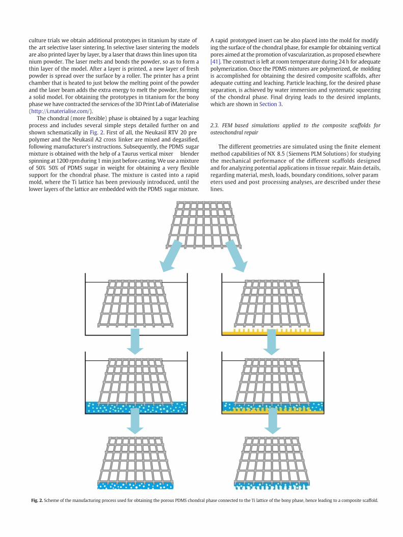
The chondral (more flexible) phase is obtained by a sugar leachingprocess and includes several simple steps detailed further on andshown schematically in Fig. 2. First of all, the Neukasil RTV 20 prepolymer and the Neukasil A2 cross linker are mixed and degasified,following manufacturer's instructions. Subsequently, the PDMS sugarmixture is obtained with the help of a Taurus vertical mixer blenderspinning at 1200 rpmduring1min just before casting.Weuse amixtureof 50% 50% of PDMS sugar in weight for obtaining a very flexiblesupport for the chondral phase. The mixture is casted into a rapidmold, where the Ti lattice has been previously introduced, until thelower layers of the lattice are embedded with the PDMS sugar mixture.
Fig. 2. Scheme of the manufacturing process used for obtaining the porous PDMS chondral ph
A rapid prototyped insert can be also placed into the mold for modifying the surface of the chondral phase, for example for obtaining verticalpores aimed at the promotion of vascularization, as proposed elsewhere[41]. The construct is left at room temperature during 24 h for adequatepolymerization. Once the PDMS mixtures are polymerized, de moldingis accomplished for obtaining the desired composite scaffolds, afteradequate cutting and leaching. Particle leaching, for the desired phaseseparation, is achieved by water immersion and systematic squeezingof the chondral phase. Final drying leads to the desired implants,which are shown in Section 3.
2.3. FEM based simulations applied to the composite scaffolds forosteochondral repair
The different geometries are simulated using the finite elementmethod capabilities of NX 8.5 (Siemens PLM Solutions) for studyingthe mechanical performance of the different scaffolds designedand for analyzing potential applications in tissue repair. Main details,regarding material, mesh, loads, boundary conditions, solver parameters used and post processing analyses, are described under theselines.
ase connected to the Ti lattice of the bony phase, hence leading to a composite scaffold.
2.4. Material and mesh
Tetrahedral 10 node elements are used formeshing,which is carriedout with the help of the automatic meshing and refine tool fromthe software employed, which provides elements with sizes below0.25 mm in almost all cases. Additionally, more than 85% of theelements obtained had a skewness value lower than 0.7, which providesadequate meshes for the purposes of the present study. Titanium alloy,with mechanical properties similar to those of the alloy used for additive manufacture of the metallic lattice structure, has been applied tothe bony phase of the composite scaffold. A soft polymer, defined withmechanical properties like those of the PDMS used for the softer layerof the composite scaffold, has been applied to the chondral phase,which has been modeled using NX 8.5 as a block with pores of450 μm, similar to the mean diameter of the sugar particles used asporogens in the sugar leaching process.
Titanium alloy bulk properties include a density of 4450 kg/m3, aYoung modulus of 117 GPa, a Poisson ratio of 0.33 and a yield strengthof 760 MPa, properties similar to those of the polymers subsequentlyused for prototype manufacture. The soft polymer resembling thePDMS has the following bulk properties: a density of 1200 kg/m3, aYoung modulus of 2.45 MPa (according to a Shore A 50 polymer), aPoisson ratio of 0.38 and a yield strength of 15 MPa.
2.5. Boundary conditions
Loads are applied as a group of punctual forces along “z” directionon the upper faces and edges of the different structures, trying topromote symmetry and homogeneous loading. A load of 500 N hasbeen vertically (−z axis) applied to the upper surface of the chondralphase. The obtained stresses are below the material's yield strength,so we can assume linearity for the subsequent post processing. Asboundary conditions, the displacements of the lower faces and edgesof the metallic lattice are fixed. Contacts between the metallic latticeand the PDMS sponge are automatically generated and perfect gluingis applied as boundary condition.
2.6. Solver parameters and post processing
From the different possibilities of NX 8.5, for carrying out FEMsimulations, “NX Nastran” solver and “structural analysis” type (solution type SESTATIC 101) are selected with the option of “element iterative solver” activated, as 3D elements are used for the simulations.Simulations are performed at a default ambient temperature of 25 °C.It is important to remark the compatibility between the design andsimulation programs, as geometries can be directly imported for simulation, without the typical limitations of universal format (.igs, .stl,.stp…) conversions and the information loss they normally involve.
Once the simulations are carried out, post processing tools allowfor a straightforward measurement of displacements for subsequentcalculation of the equivalent Young moduli of the different parts of thecomposite scaffold, as further discussed in Section 3.2. Details regardingthe results from the simulations developed are presented, summarizedand discussed in Section 3.
2.7. Cell culture process for in vitro validation
The hMSCs used in thisworkwere isolated in a Percoll gradient from1 or 2 ml of human bone marrow samples from anonymous healthydonors and provided by hematology services of theHospital La Princesa,the Jiménez Díaz Foundation and theUniversity Biobank ofMálaga, andexpanded as described previously [42,43]. Cells were plated andincubated using DMEM L plus 10% FBS of selected batches. Cells werecollected by treatment with 0.25% trypsin EDTA. Cell culture mediumswere prepared by the research services of Molecular Biology Center“Severo Ochoa” (CSIC UAM).
For the preparation of CM hMSC we used 8 10 p100 culture platesat 80% confluence for each batch. Cells were washed with PBS and incubated in DMEM L starved of FBS and supplemented with 2 mM pyruvate during 24 h. Afterwards culture medium was collected, cleaned ofany floating cell by centrifugation at 1500 rpm in a bench centrifugeduring 5 min. The clean supernatant was cooled down on ice during30 min, centrifuged in a Sorvall to remove salt precipitations andkept in 2 ml aliquots at −30 °C until use. We avoid any samples withrepeated freeze thaw.
The lattice scaffolds were UV irradiated, individually placed in 25mlFalcon tubes and received the following treatment: i) wash using 0.5mlPBS and 5 min centrifugation; ii) treatment with 2 M acetic acid during20 min, rapid neutralization and PBS wash; iii) treatment with hMSCCM during 24 h or DMEM LG as control; and iv) scaffold seedwith 150,000 hMSC and incubation in DMEM L 10% FBS during 48 hat 37 °C in 5% CO2 as early indicated [44,45]. Then, the lattice scaffoldswere cut into smaller slices and pieces, individually placed in M24tissue dishes, rinsed with ice cold PBS and fixed in 3.7% formaldehydein PBS during 30 min at RT and washed in PBS. Afterwards, sampleswere washed with PBS and fixed in 3.7% formaldehyde in PBS during30 min and processed for immunofluorescence [46,47]. To this end,cells were permeated and all cell soluble proteins were removed byincubation with 0.5% Triton in a CSK buffer containing 10 mM pipes,pH 6.8, 3 mM MgCl2, 100 mM NaCl, 1 mM EGTA, 0.3 M sucrose for30 min on ice. After the treatment, samples were cleaned and fixedwith 3.7% formaldehyde and equilibrated in PBS. Nuclei were stainedwithDAPI (CALBIOCHEM) and observed using an inverted IX81Olympuscoupled with a DP72 digital camera. Cytoskeleton was observed bydeterminingα Tubulin (1:2000, Sigma) and amouse derived secondaryantibody labeled with Alexa 488 (1:500, Invitrogen) for finally addressing the energetic behavior of the cells and their viability upon thescaffolds.
3. Results and discussion
3.1. Validation of the design and manufacturing process
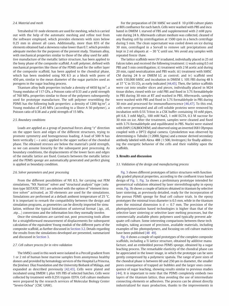
Fig. 3 shows different prototypes of lattice structures with functionally graded physical properties, according to the confluent truss baseddesign of Fig. 1. Fig. 3a shows a preliminary prototype intended forgeometrical validation obtained by laser stereolithography in epoxyresin. Fig. 3b shows a couple of lattices obtained in titanium by selectivelaser sintering, as previously detailed, ready for the incorporation ofthe porous PDMS sponge for final cell culture trials. In the epoxyprototypes theminimal truss diameter is 0.5 mm, while in the titaniumones the minimal dimension is d = 0.7 mm. The precision of thephotopolymerization based technologies is higher than that of theselective laser sintering or selective laser melting processes, but thecommercially available photo polymers used typically prevent adequate cell culture. Some interesting comparisons between these technologies, taking account of precision, available materials, includingexamples of bio photopolymers, and focusing on cell culture matriceshave been published [48 49].
Fig. 4 shows a couple of rapid prototypes of the complete compositescaffolds, including a Ti lattice structure, obtained by additive manufacture, and an embedded porous PDMS sponge, obtained by a sugarleaching process. The remarkable elasticity of the chondral phase canbe appreciated in the lower image, in which the prototype can be seengently compressed by a polymeric spatula. The range of pore sizes ofthe chondral phase is between 60 and 250 μm in diameter, the smallerpores consequence of trapped air bubbles and the larger ones consequence of sugar leaching, showing results similar to previous studies[44]. It is important to note that the PDMS completely embeds twolayers of the titanium lattice, thus avoiding the use of intermediateconnecting elements or adhesives. The process can be almost directlyindustrialized for mass production, thanks to the improvements in
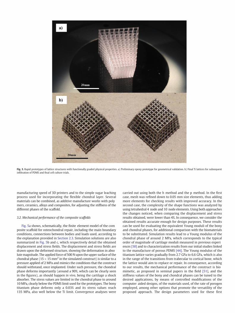
Fig. 3. Rapid prototypes of lattice structures with functionally graded physical properties. a) Preliminary epoxy prototype for geometrical validation. b) Final Ti lattices for subsequentinfiltration of PDMS and final cell culture trials.
manufacturing speed of 3D printers and to the simple sugar leachingprocess used for incorporating the flexible chondral layer. Severalmaterials can be combined, as additive manufacture works with polymers, ceramics, alloys and composites, for adjusting the stiffness of thedifferent phases of the scaffold.
3.2. Mechanical performance of the composite scaffolds
Fig. 5a shows, schematically, the finite element model of the composite scaffold for osteochondral repair, including the main boundaryconditions, connections between bodies and loads used, according tothe explanation provided in Section 2.3. Simulation solutions are alsosummarized in Fig. 5b and c, which respectively detail the obtaineddisplacement and stress fields. The displacement and stress fields aredrawn upon the deformed structure, showing the deformation in absolutemagnitude. The applied force of 500Nupon the upper surface of thechondral phase (15 × 15mm2 in the simulated construct) is similar to apressure applied of 2 MPa and mimics the conditions that the constructshould withstand, once implanted. Under such pressure, the chondralphase deforms importantly (around a 90%, which can be clearly seenin the figures), as should happen in vivo, being the cartilage a shockabsorber. The stress values are limited in the chondral phase to around10MPa, clearly below the PDMS limit used for the prototypes. The bonytitanium phase deforms only a 0.03% and its stress values reach135 MPa, also well below the Ti limit. Convergence analyses were
carried out using both the h method and the p method. In the firstcase, mesh was refined down to 0.05 mm size elements, thus addingmore elements for checking results with improved accuracy. In thesecond case, the complexity of the shape functions was analyzed byusing tetrahedral 4 node and 10 node elements. Using both approachesthe changes noticed, when comparing the displacement and stressresults obtained, were lower than 4%. In consequence, we consider theobtained results accurate enough for design purposes. These resultscan be used for evaluating the equivalent Young moduli of the bonyand chondral phases, for additional comparison with the biomaterialsto be substituted. Simulation results lead to a Young modulus of thechondral phase of around 2 MPa, which corresponds to the typicalorder of magnitude of cartilage moduli measured in previous experiences [50] and to characterization results from our initial studies linkedto the manufacture of porous PDMS [44]. The Young modulus of thetitanium lattice varies gradually from 2.7 GPa to 6.6 GPa, which is alsoin the range of the transitions from trabecular to cortical bone, whichthe lattice would aim to replace or repair. In consequence, accordingto our results, the mechanical performance of the construct is biomimetic, as proposed in seminal papers in the field [51], and thestiffness values of the bony and chondral phases can be tuned to thedesired applications, by means of controlled modifications of thecomputer aided designs, of the materials used, of the rate of porogenemployed, among other options that promote the versatility of theproposed approach. The design parameters used for these first
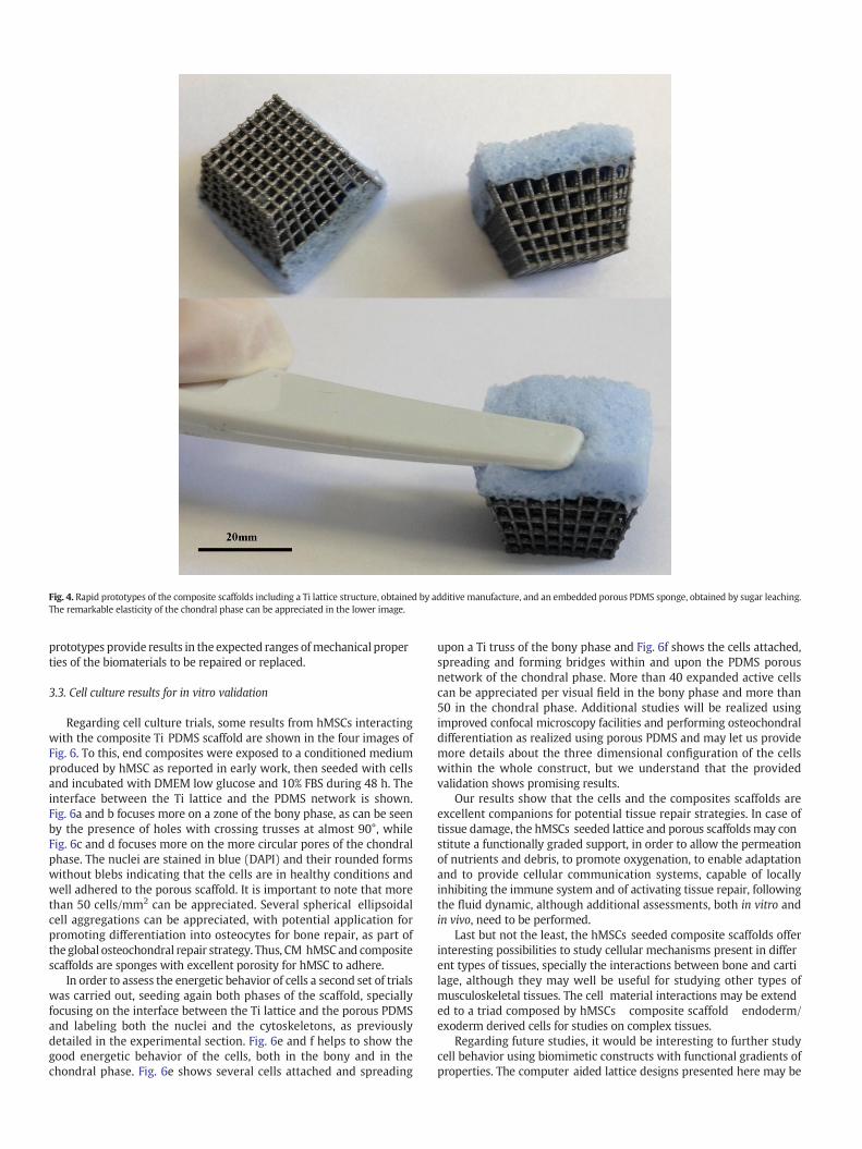
Fig. 4. Rapid prototypes of the composite scaffolds including a Ti lattice structure, obtained by additive manufacture, and an embedded porous PDMS sponge, obtained by sugar leaching.The remarkable elasticity of the chondral phase can be appreciated in the lower image.
prototypes provide results in the expected ranges ofmechanical properties of the biomaterials to be repaired or replaced.
3.3. Cell culture results for in vitro validation
Regarding cell culture trials, some results from hMSCs interactingwith the composite Ti PDMS scaffold are shown in the four images ofFig. 6. To this, end composites were exposed to a conditioned mediumproduced by hMSC as reported in early work, then seeded with cellsand incubated with DMEM low glucose and 10% FBS during 48 h. Theinterface between the Ti lattice and the PDMS network is shown.Fig. 6a and b focuses more on a zone of the bony phase, as can be seenby the presence of holes with crossing trusses at almost 90°, whileFig. 6c and d focuses more on the more circular pores of the chondralphase. The nuclei are stained in blue (DAPI) and their rounded formswithout blebs indicating that the cells are in healthy conditions andwell adhered to the porous scaffold. It is important to note that morethan 50 cells/mm2 can be appreciated. Several spherical ellipsoidalcell aggregations can be appreciated, with potential application forpromoting differentiation into osteocytes for bone repair, as part ofthe global osteochondral repair strategy. Thus, CM hMSCand compositescaffolds are sponges with excellent porosity for hMSC to adhere.
In order to assess the energetic behavior of cells a second set of trialswas carried out, seeding again both phases of the scaffold, speciallyfocusing on the interface between the Ti lattice and the porous PDMSand labeling both the nuclei and the cytoskeletons, as previouslydetailed in the experimental section. Fig. 6e and f helps to show thegood energetic behavior of the cells, both in the bony and in thechondral phase. Fig. 6e shows several cells attached and spreading
upon a Ti truss of the bony phase and Fig. 6f shows the cells attached,spreading and forming bridges within and upon the PDMS porousnetwork of the chondral phase. More than 40 expanded active cellscan be appreciated per visual field in the bony phase and more than50 in the chondral phase. Additional studies will be realized usingimproved confocal microscopy facilities and performing osteochondraldifferentiation as realized using porous PDMS and may let us providemore details about the three dimensional configuration of the cellswithin the whole construct, but we understand that the providedvalidation shows promising results.
Our results show that the cells and the composites scaffolds areexcellent companions for potential tissue repair strategies. In case oftissue damage, the hMSCs seeded lattice and porous scaffoldsmay constitute a functionally graded support, in order to allow the permeationof nutrients and debris, to promote oxygenation, to enable adaptationand to provide cellular communication systems, capable of locallyinhibiting the immune system and of activating tissue repair, followingthe fluid dynamic, although additional assessments, both in vitro andin vivo, need to be performed.
Last but not the least, the hMSCs seeded composite scaffolds offerinteresting possibilities to study cellular mechanisms present in different types of tissues, specially the interactions between bone and cartilage, although they may well be useful for studying other types ofmusculoskeletal tissues. The cell material interactions may be extended to a triad composed by hMSCs composite scaffold endoderm/exoderm derived cells for studies on complex tissues.
Regarding future studies, it would be interesting to further studycell behavior using biomimetic constructs with functional gradients ofproperties. The computer aided lattice designs presented here may be
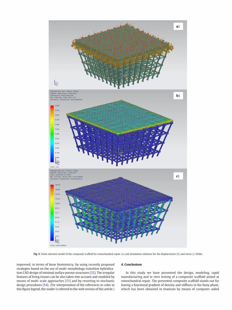
Fig. 5. Finite-element model of the composite scaffold for osteochondral repair (a) and simulation solutions for the displacement (b) and stress (c) fields.
improved, in terms of bone biomimicry, by using recently proposedstrategies based on the use of multi morphology transition hybridization CAD design of minimal surface porous structures [52]. The irregularfeatures of living tissues can be also taken into account and modeled bymeans of multi scale approaches [53] and by resorting to stochasticdesign procedures [54]. (For interpretation of the references to color inthisfigure legend, the reader is referred to thewebversion of this article.)
4. Conclusions
In this study we have presented the design, modeling, rapidmanufacturing and in vitro testing of a composite scaffold aimed atosteochondral repair. The presented composite scaffold stands out forhaving a functional gradient of density and stiffness in the bony phase,which has been obtained in titanium by means of computer aided
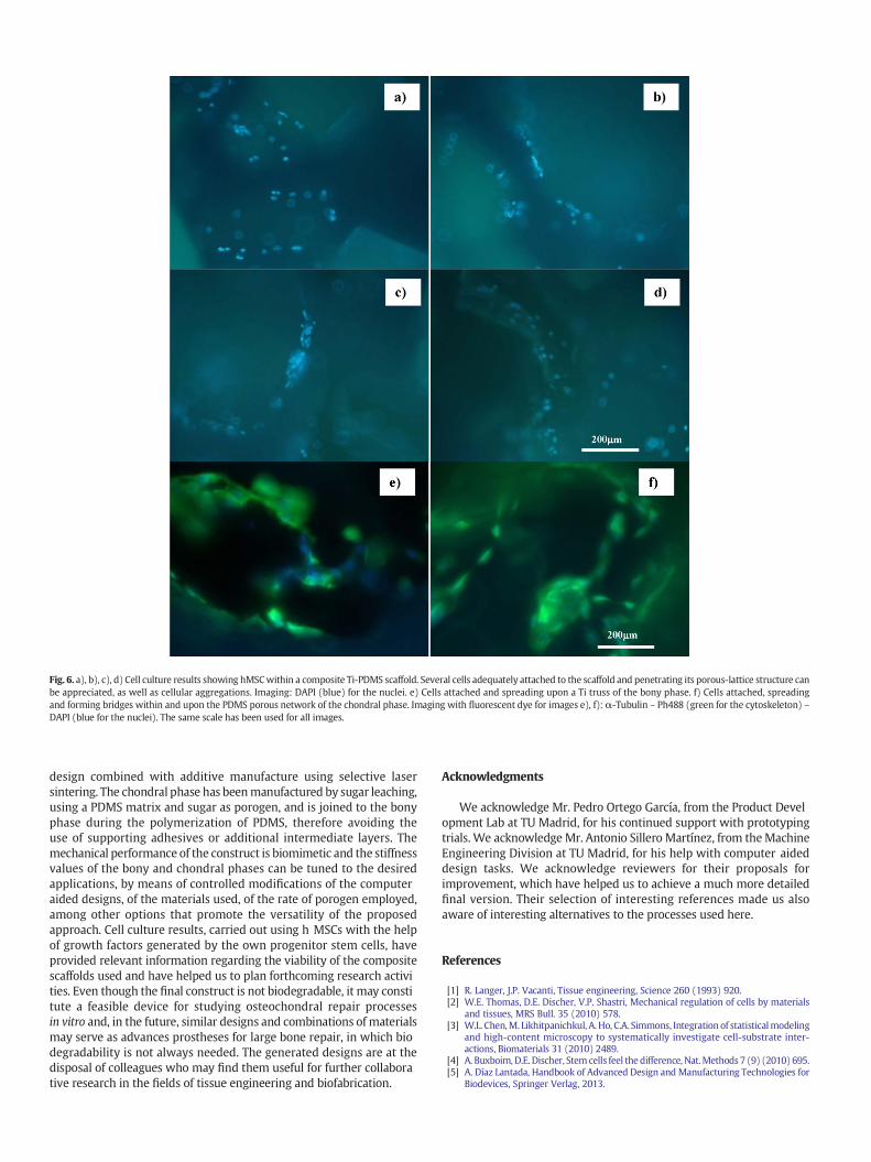
Fig. 6. a), b), c), d) Cell culture results showing hMSCwithin a composite Ti-PDMS scaffold. Several cells adequately attached to the scaffold and penetrating its porous-lattice structure canbe appreciated, as well as cellular aggregations. Imaging: DAPI (blue) for the nuclei. e) Cells attached and spreading upon a Ti truss of the bony phase. f) Cells attached, spreadingand forming bridges within and upon the PDMS porous network of the chondral phase. Imaging with fluorescent dye for images e), f): α-Tubulin – Ph488 (green for the cytoskeleton) –DAPI (blue for the nuclei). The same scale has been used for all images.
design combined with additive manufacture using selective lasersintering. The chondral phase has beenmanufactured by sugar leaching,using a PDMS matrix and sugar as porogen, and is joined to the bonyphase during the polymerization of PDMS, therefore avoiding theuse of supporting adhesives or additional intermediate layers. Themechanical performance of the construct is biomimetic and the stiffnessvalues of the bony and chondral phases can be tuned to the desiredapplications, by means of controlled modifications of the computeraided designs, of the materials used, of the rate of porogen employed,among other options that promote the versatility of the proposedapproach. Cell culture results, carried out using h MSCs with the helpof growth factors generated by the own progenitor stem cells, haveprovided relevant information regarding the viability of the compositescaffolds used and have helped us to plan forthcoming research activities. Even though the final construct is not biodegradable, it may constitute a feasible device for studying osteochondral repair processesin vitro and, in the future, similar designs and combinations of materialsmay serve as advances prostheses for large bone repair, in which biodegradability is not always needed. The generated designs are at thedisposal of colleagues who may find them useful for further collaborative research in the fields of tissue engineering and biofabrication.
Acknowledgments
We acknowledge Mr. Pedro Ortego García, from the Product Development Lab at TU Madrid, for his continued support with prototypingtrials. We acknowledge Mr. Antonio Sillero Martínez, from theMachineEngineering Division at TU Madrid, for his help with computer aideddesign tasks. We acknowledge reviewers for their proposals forimprovement, which have helped us to achieve a much more detailedfinal version. Their selection of interesting references made us alsoaware of interesting alternatives to the processes used here.
References
[1] R. Langer, J.P. Vacanti, Tissue engineering, Science 260 (1993) 920.[2] W.E. Thomas, D.E. Discher, V.P. Shastri, Mechanical regulation of cells by materials
and tissues, MRS Bull. 35 (2010) 578.[3] W.L. Chen,M. Likhitpanichkul, A. Ho, C.A. Simmons, Integration of statisticalmodeling
and high-content microscopy to systematically investigate cell-substrate inter-actions, Biomaterials 31 (2010) 2489.
[4] A. Buxboim, D.E. Discher, Stem cells feel the difference, Nat.Methods 7 (9) (2010) 695.[5] A. Díaz Lantada, Handbook of Advanced Design and Manufacturing Technologies for
Biodevices, Springer Verlag, 2013.
[6] P.J.S. Bartolo, H. Almeida, T. Laoui, Rapid prototyping and manufacturing for tissueengineering scaffolds, Int. J. Comput. Appl. Technol. 36 (2009) 1.
[7] J.Y. Tan, C.K. Chua, K.F. Leong, Indirect fabrication of gelatin scaffolds using rapidprototyping technology, Virtual Phys. Prototyping 5 (1) (2010) 45.
[8] A.K. Ekaputra, Y. Zhou, S.M.K. Cool, D.M.Hutmacher, Composite electrospun scaffoldsfor engineering tubular bone grafts, Tissue Eng. A 15 (12) (2009) 3779.
[9] S. Lohfeld, M.A. Tyndyk, S. Cahill, N. Flaherty, V. Barron, P.E. Mc Hugh, A method tofabricate small features on scaffolds for tissue engineering via selective lasersintering, J. Biomed. Sci. Eng. 3 (2010) 138.
[10] R. Tzezana, E. Zussman, S.A. Levenberg, Ultra-porous scaffold for tissue engineering,created via a hydrospinning method, Tissue Eng. Part C 14 (4) (2008) 281.
[11] A. Díaz Lantada, A. Mosquera, J.L. Endrino, P. Lafont, Design and rapid prototyping ofDLC coated fractal surfaces for tissue engineering applications, J. Appl. Phys. Conf.Ser. 252 (2010) 012003.
[12] J. Stampfl, H. Fouad, S. Seidler, R. Liska, R.F. Schwanger, A. Woesz, P. Fratzl, Fabrica-tion and moulding of cellular materials by rapid prototyping, Int. J. Mater. Prod.Technol. 21 (4) (2004) 285.
[13] R. Infür, N. Pucher, C. Heller, H. Lichtenegger, R. Liska, V. Schmidt, L. Kuna, A. Haase, J.Stampfl, Functional polymers by two-photon 3D lithography, Appl. Surf. Sci. 254(2007) 836.
[14] P.S. Maher, R.P. Keatch, K. Donnelly, Z. Paxton, Formed 3D Bio-scaffolds Via RapidPrototyping Technology, Presented at 4th European Conference of the IFMBE,IFMBE Proceedings, 22(17) 2009, p. 2200.
[15] G.E. Ryan, A.S. Pandit, D. Apatsidis, Porous titanium scaffolds fabricated using a rapidprototyping and powder metallurgy technique, Biomaterials 29 (2008) 3625.
[16] P.H. Warnke, T. Douglas, P. Wollny, E. Sherry, M. Steiner, S. Galonska, S.T. Becker, I.N.Springer, J. Wiltfang, S. Sivananthan, Rapid prototyping: porous titanium alloy scaf-folds produced by selective laser melting for bone tissue engineering, Tissue Eng.Part C Methods 15 (2) (2009) 115.
[17] J. Stampfl, S. Baudis, C. Heller, R. Liska, A. Neumeister, R. Kling, A. Ostendorf, M.Spitzbart, Photopolymers with tunable mechanical properties processed by laser-based high-resolution stereolitoraphy, J. Micromech. Microeng. 18 (2008) 125014.
[18] S.C. Cox, J.A. Thornby, G.J. Gibbons, M.A.Williams, K.K. Mallick, 3D printing of poroushydroxyapatite scaffolds intended for use in bone tissue engineering applications,Mater. Sci. Eng. C 47 (2015) 237–247.
[19] M. Schuster, C. Turecek, B. Kaiser, J. Stampfl, R. Liska, F. Varga, Evaluation of bio-compatible photopolymers. I: photoreactivity and mechanical properties of reactivediluents, J. Macromol. Sci. A 44 (2007) 547.
[20] M. Schuster, C. Turecek, B. Kaiser, J. Stampfl, R. Liska, F. Varga, Evaluation of bio-compatible photopolymers II: Further reactive diluents, Monatsh. Chem. 138(2007) 261.
[21] F. Jung, C. Wischke, A. Lendlein, Multifunctional cardiovascular implants: challengesand hurdles, MRS Bull. 35 (2010) 607.
[22] J.Y. Tan, C.K. Chua, K.F. Leong, Fabrication of channeled scaffolds with ordered arrayof micro-pores through microsphere leaching and indirect rapid prototypingtechnique, Biomed. Microdevices 15 (2013) 83.
[23] C.K.F. Chan, C.C. Chen, C.A. Luppen, D.L. Kraft, J.B. Kim, A. De Boer, K. Wei, J.A. Helms,C.J. Kuo, I.L. Weissman, Endochondral ossification is required for hematopoieticstem cell niche formation, Nature 457 (7228) (2009) 490.
[24] T.P. Richardson, M.C. Peters, A.B. Ennett, D.J. Mooney, Polymeric system for dualgrowth factor delivery, Nat. Biotechnol. 19 (2001) 1029.
[25] A. Perets, Y. Baruch, F. Weisbuch, G. Shoshany, V. Neufeld, S. Cohen, Enhancing thevascularization of three-dimensional porous alginate scaffolds by incorporatingcontrolled release basic fibroblast growth factor microspheres, J. Biomed. Mater.Res. A 65 (4) (2003) 489.
[26] M.W. Laschke, M. Rücker, G. Jensen, C. Carvalho, R. Mülhaupt, N.C. Gellrich, M.D.Menger, Incorporation of growth factor containingMatrigel promotes vascularizationof porous PLGA scaffolds, J. Biomed. Mater. Res. A 85 (2) (2008) 397.
[27] F.T.Moutos, F. Guilak, Composite scaffolds for cartilage tissue engineering, Biorheology45 (3-4) (2008) 501–512.
[28] P. Nooeaid, V. Salih, J.P. Beier, A.R. Boccaccini, Osteochondral tissue engineering:scaffolds, stem cells and applications, J. Cell. Mol. Med. 16 (10) (2012) 2247–2270.
[29] E. Kon, A. Mutini, E. Arcangeli, M. Delcogliano, G. Filardo, N.N. Aldini, D. Pressato, R.Quarto, S. Zaffagnini, M. Marcacci, Novel nanostructured scaffold for osteochondralregeneration: pilot study in horses, J. Tissue Eng. Regen. Med. (2009)http://dx.doi.org/10.1002/term.243.
[30] E.J. Caterson, L.J. Nesti, W.J. Li, K.G. Danielson, T.J. Albert, A.R. Vaccaro, R.S. Tuan,Three-dimensional cartilage formation by bone marrow-derived cells seeded ionpolylactide/alginate amalgam, J. Biomed. Mater. Res. 57 (2001) 394–403.
[31] J.K. Sheerwood, S.L. Riley, R. Palazzolo, S.C. Brown, D.C. Monkhouse, M. Coates, L.G.Griffith, L.K. Landeen, A. Ratcliffe, A three-dimensional osteochondral compositescaffold for articular cartilage repair, Biomaterials 23 (2008) 4739–4751.
[32] R.M. Schek, J.M. Taboas, S.J. Hollister, P.H. Krebsbach, Tissue engineeringosteochondral implants for temporomandibular joint repair, Orthod. CraniofacialRes. 8 (2005) 313–319.
[33] W. Sun, B. Starly, J. Nam, A. Darling, Bio-CAD modeling and its application incomputer-aided tissue engineering, Comput. Aided Des. 37 (11) (2005) 1097–1114.
[34] H. Da, S.-J. Jia, G.-L. Meng, J.-H. Cheng, W. Zhou, Z. Xiong, Y.-J. Mu, J. Liu, The impactof compact layer on osteochondral tissue engineering, PLoS ONE 8 (1) (2013),e54838.
[35] K. Alvarez, H. Nakajima, Metallic scaffolds for bone regeneration, Materials 2 (2009)790–832.
[36] X. Zhang,W. Chang, P. Lee, Y.Wang,M. Yang, J. Li, S.G. Kumbar, X. Yu, Polymer-ceramicspiral structured scaffolds for bone tissue engineering: effect of hydroxyapatite,composition on human fetal osteoblasts, PLoS ONE (2014) 9(1).
[37] H.-W. Kang, J.H. Park, T.-Y. Kang, Y.-J. Seol, D.-W. Cho, Unit cell-based computer-aided manufacturing system for tissue engineering, Biofabrication 4 (2012) 015055.
[38] Y. Hakamatsuka, H. Irie. Prosthetic artificial bone having ceramic layers of differentporosity. US Patent 5152791 A, 1989.
[39] C. Zhao, H. Zhang, B. Cai, G. Wang, H. Fan, X. Zhang, Preparation of porous PLGA/Tibiphasic scaffold and osteochondral defect repair, Biomater. Sci. 1 (7) (2013)703–710.
[40] M.P. Staiger, A.M. Pietak, J. Huadmai, G. Diaz, Magnesium and its alloys as orthopedicbiomaterials: a review, Biomaterials 27 (9) (2006) 1728–1734.
[41] H.C.S. Ko, B.K. Milthorpe, C.D. Mc Farland, Engineering thick tissues — the vascular-ization problem, Eur. Cell. Mater. 14 (2007) 1–19.
[42] D.P. Lennon, S.E. Haynesworth, S.P. Bruder, N. Jaiswal, A.I. Caplan, Human andanimal mesenchymal progenitor cells from bone marrow: identification of serumfor optimal selection and proliferation, In vitro Cell. Dev. Biol. 32 (2006) 602.
[43] S. Ogueta, J. Muñoz, E. Obregon, E. Delgado-Baeza, J.P. García-Ruiz, Prolactin is acomponent of the human sinovial liquid andmodulates thegrowth and chondrogenicdifferentiation of bone marrow-derived mesenchymal stem cells, Mol. Cell.Endocrinol. 190 (1-2) (2002) 51.
[44] A. Díaz Lantada, H. Alarcón Iniesta, B. Pareja Sánchez, J.P. García-Ruíz, Free-formrapid-prototyped PDMS scaffolds incorporating growth factors promote chondro-genesis, Adv. Mater. Sci. Eng. (2014), 612976.
[45] M.F. Pittenger, A.M. Mackay, S.C. Beck, R.K. Jaiswal, R. Douglas, J.D. Mosca, M.A.Moorman, D.W. Simonetti, S. Craig, D.R. Marshak, Multilineage potential of adulthuman mesenchymal stem cells, Science 284 (5411) (1999) 143.
[46] M. Romero-Prado, C. Blázquez, C. Rodríguez-Navas, J. Muñoz, I. Guerrero, E.Delgado-Baeza, J.P. García-Ruiz, Functional characterization of humanmesenchymalstem cells that maintain osteochondral fates, J. Cell. Biochem. 98 (2006) 1457.
[47] A. Javed, B. Guo, S. Hiebert, J.Y. Choi, J. Green, S.C. Zhao, M.A. Osborne, S. Stifani, J.L.Stein, J.B. Lian, A.J. vanWijnen, G.S. Stein, Groucho/TLE/R-esp proteins associatewiththe nuclear matrix and repress RUNX (CBF (alpha)/AML/PEBP2(alpha)) dependentactivation of tissue-specific gene transcription, J. Cell Sci. 113 (Pt 12) (2000) 2221.
[48] A. Ovsianikov, V. Mironov, J. Stampfl, R. Liska, Engineering 3D cell-culture matrices:multiphoton processing technologies for biological & tissue engineering applica-tions, Expert Rev. Med. Devices 9 (6) (2012) 613–633.
[49] A. Díaz Lantada, B. Pareja Sánchez, C. Gómez Murillo, J. Urbieta Sotillo, Fractals intissue engineering: towards biomimetic cell-culture matrices, microsystems andmicrostructured implants, Expert Rev. Med. Devices 10 (5) (2013) 629–648.
[50] J.M. Mansour, Biomechanics of Cartilage, in: C.A. Oatis (Ed.), Kinesiology: TheMechanics and Pathomechanics of Human Movement, Lippincott Williams andWilkins, 2003.
[51] D.W. Hutmacher, Scaffolds in tissue engineering and bone cartilage, Biomaterials 21(24) (2000) 2529–2543.
[52] N. Yang, Z. Quan, D. Zhang, Y. Tian, Multi-morphology transition hybridization CADdesign of minimal surface porous structures for use in tissue engineering, Comput.Aided Des. 56 (2014) 11–21.
[53] N. Yang, K. Zhou, Effective method for multi-scale gradient porous scaffold designand fabrication, Mater. Sci. Eng. C 43 (1) (2014) 502–505.
[54] N. Yang, L. Gao, K. Zhou, Simple method to generate and fabricate stochastic porousscaffolds, Mater. Sci. Eng. C 56 (1) (2015) 444–450.