Embed Size (px)
Citation preview
Compressed air quality made to measure
Sketch made with RENNER Planner Software – available to RENNER distributors on request
Compressed air treatment
Cyclone separators / Air filters / Condensate drains / Refrigeration dryers / Oil-water separators
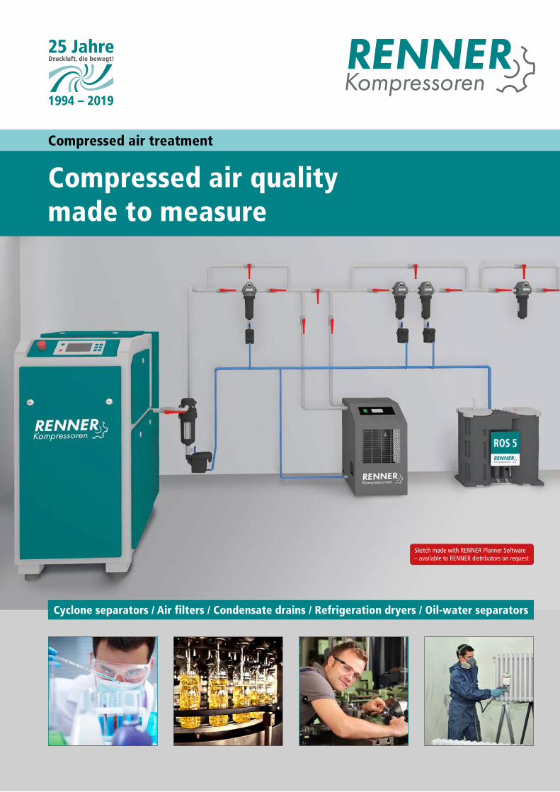
Cyclone separator
Condensate is separated at the compressed air outlet of the compressor
Oil-water separators
Separation of oil and condensate
Compressed air treatment and accessories
Compressed air is used in almost all industrial sectors. The demands on their quality and purity varydepending on the application. RENNER offers the right products and solutions for all requirements.
Refrigeration dryer
Protection against condensation
Air filter / three-stages-filter
In different filtration classes according to ISO 8573:1 for clean compressed air
Adsorption dryer
Clean and dry compressed air with low pressure dew point according to ISO 8573:1
Adsorption dryer
For reliable removal of oil vapours, hydrocarbons and odours.
Pressure maintaining system
Flawless compressed air treatment guaranteed
Electric ball valve
Slow opening hours for a safe compressed air treatment
Condensate drain
Discharge of condensate without unnecessary compressed air losses
2
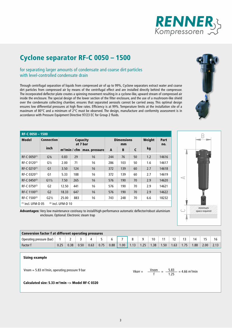
Cyclone separator RF-C 0050 – 1500
for separating larger amounts of condensate and coarse dirt particleswith level-controlled condensate drain
Through centrifugal separation of liquids from compressed air of up to 99%, Cyclone separators extract water and coarse dirt particles from compressed air by means of the centrifugal effect and are installed directly behind the compressor. The incorporated deflector plate creates a spinning movement resulting in a cyclone-like, upward stream of compressed air inside the enclosure. The special design of the lower section of the filter enclosure, and the use of a mushroom-like shield over the condensate collecting chamber, ensures that separated aerosols cannot be carried away. This optimal design ensures low differential pressures at high flow rates. Efficiency is at 99%. Temperature limits at the installation site of a maximum of 80°C and a minimum of 2°C must be observed. The design, manufacture and conformity assessment is in accordance with Pressure Equipment Directive 97/23 EC for Group 2 fluids.
RF-C 0050 – 1500
Model Connection
inch
Capacity at 7 bar
Dimensions mm
Weight
kg
Part no.
m3/min / cfm max. pressure A B C
RF-C 0050(1) G3 8 0.83 29 16 244 76 50 1.2 14616
RF-C 0120(1) G½ 2.00 71 16 286 103 50 1.6 14617
RF-C 0210(1) G1 3.50 124 16 372 139 60 2.7 14618
RF-C 0320(1) G1 5.33 188 16 372 139 60 2.7 14619
RF-C 0450(2) G1½ 7.50 265 16 576 190 70 2.9 14620
RF-C 0750(2) G2 12.50 441 16 576 190 70 2.9 14621
RF-C 1100(2) G2 18.33 647 16 576 190 70 2.9 14622
RF-C 1500(2) G2½ 25.00 883 16 743 248 70 6.6 18232(1) incl. UFM-D 05 (2) incl. UFM-D 10
minimum space required
Sizing example
Calculated size: 5.33 m3/min –> Model RF-C 0320
Vkorr = Vnomf
= 5.831.25
= 4.66 m3/minVnom = 5.83 m3/min, operating pressure 9 bar
Advantages: Very low maintenance cost/easy to install/high-performance automatic deflector/robust aluminium enclosure. Optional: Electronic steam trap
Conversion factor f at different operating pressures
Operating pressure (bar) 1 2 3 4 5 6 7 8 9 10 11 12 13 14 15 16
Factor f 0.25 0.38 0.50 0.63 0.75 0.88 1.00 1.13 1.25 1.38 1.50 1.63 1.75 1.88 2.00 2.13
3
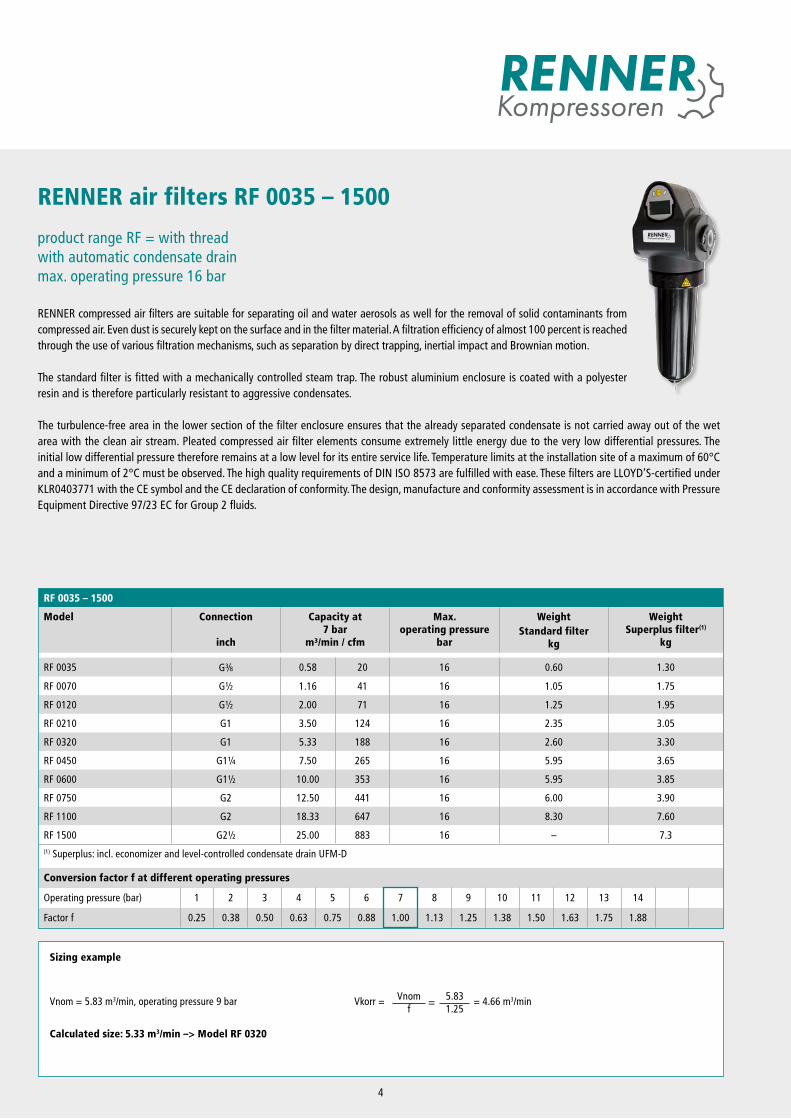
RENNER air filters RF 0035 – 1500
product range RF = with threadwith automatic condensate drainmax. operating pressure 16 bar
RENNER compressed air filters are suitable for separating oil and water aerosols as well for the removal of solid contaminants from compressed air. Even dust is securely kept on the surface and in the filter material. A filtration efficiency of almost 100 percent is reached through the use of various filtration mechanisms, such as separation by direct trapping, inertial impact and Brownian motion.
The standard filter is fitted with a mechanically controlled steam trap. The robust aluminium enclosure is coated with a polyester resin and is therefore particularly resistant to aggressive condensates.
The turbulence-free area in the lower section of the filter enclosure ensures that the already separated condensate is not carried away out of the wet area with the clean air stream. Pleated compressed air filter elements consume extremely little energy due to the very low differential pressures. The initial low differential pressure therefore remains at a low level for its entire service life. Temperature limits at the installation site of a maximum of 60°C and a minimum of 2°C must be observed. The high quality requirements of DIN ISO 8573 are fulfilled with ease. These filters are LLOYD’S-certified under KLR0403771 with the CE symbol and the CE declaration of conformity. The design, manufacture and conformity assessment is in accordance with Pressure Equipment Directive 97/23 EC for Group 2 fluids.
Sizing example
Calculated size: 5.33 m3/min –> Model RF 0320
Vkorr = Vnomf
= 5.831.25
= 4.66 m3/minVnom = 5.83 m3/min, operating pressure 9 bar
RF 0035 – 1500
Model Connection
inch
Capacity at7 bar
m³/min / cfm
Max. operating pressure
bar
WeightStandard filter
kg
Weight Superplus filter(1)
kg
RF 0035 G3 8 0.58 20 16 0.60 1.30
RF 0070 G½ 1.16 41 16 1.05 1.75
RF 0120 G½ 2.00 71 16 1.25 1.95
RF 0210 G1 3.50 124 16 2.35 3.05
RF 0320 G1 5.33 188 16 2.60 3.30
RF 0450 G1¼ 7.50 265 16 5.95 3.65
RF 0600 G1½ 10.00 353 16 5.95 3.85
RF 0750 G2 12.50 441 16 6.00 3.90
RF 1100 G2 18.33 647 16 8.30 7.60
RF 1500 G2½ 25.00 883 16 – 7.3(1) Superplus: incl. economizer and level-controlled condensate drain UFM-D
Conversion factor f at different operating pressures
Operating pressure (bar) 1 2 3 4 5 6 7 8 9 10 11 12 13 14
Factor f 0.25 0.38 0.50 0.63 0.75 0.88 1.00 1.13 1.25 1.38 1.50 1.63 1.75 1.88
4
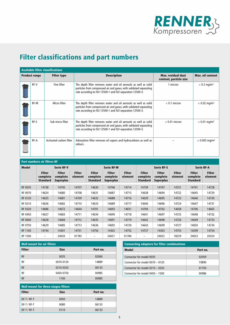
Filter classifications and part numbers
Available filter classifications
Product range Filter type Description Max. residual dust content, particle size
Max. oil content
RF-V Fine filter The depth filter removes water and oil aerosols as well as solid particles from compressed air and gases, with validated separating rate according to ISO 12500-1 and ISO separation 12500-3.
1 micron < 0.2 mg/m³
RF-M Micro filter The depth filter removes water and oil aerosols as well as solid particles from compressed air and gases, with validated separating rate according to ISO 12500-1 and ISO separation 12500-3.
< 0.1 micron < 0.02 mg/m³
RF-S Sub micro filter The depth filter removes water and oil aerosols as well as solid particles from compressed air and gases, with validated separating rate according to ISO 12500-1 and ISO separation 12500-3.
< 0.01 micron < 0.01 mg/m³
RF-A Activated carbon filter Adsorption filter removes oil vapors and hydrocarbons as well as odours.
– < 0.003 mg/m³
Wall mount for air filters
Filter Size Part no.
RF 0035 02060
RF 0070-0120 14889
RF 0210-0320 06133
RF 0450-0750 00985
RF 1100 00985
Wall mount for three-stages-filters
Filter Size Part no.
DF-T / RF-T 0050 14889
DF-T / RF-T 0080 06133
DF-T / RF-T 0110 06133
5
Part numbers air filters RF
Model Serie RF-V Serie RF-M Serie RF-S Serie RF-A
Filter complete Standard
Filter complete Superplus
Filter element
Filter complete Standard
Filter complete Superplus
Filter element
Filter complete Standard
Filter complete Superplus
Filter element
Filter complete Standard
Filter element
RF 0035 14738 14745 14707 14630 14746 14714 14739 14747 14721 14741 14728
RF 0070 14624 14680 14708 14631 14687 14715 14638 14694 14722 14645 14729
RF 0120 14625 14681 14709 14632 14688 14716 14639 14695 14723 14646 14730
RF 0210 14626 14682 14710 14633 14689 14717 14640 14696 14724 14647 14731
RF 0320 14686 14672 14644 14701 14693 14651 14704 14702 14658 14706 14665
RF 0450 14627 14683 14711 14634 14690 14718 14641 14697 14725 14648 14732
RF 0600 14628 14684 14712 14635 14691 14719 14642 14698 14726 14649 14733
RF 0750 14629 14685 14713 14636 14692 14720 14643 14699 14727 14650 14734
RF 1100 14744 14301 14751 14756 14302 14752 14737 14303 14753 14299 14754
RF 1500 – 24020 01783 – 24021 01784 – 24022 18229 24023 20324
Connecting adapters for filter combinations
Model Part no.
Connector for model 0035 02059
Connector for model 0070 – 0120 19890
Connector for model 0210 – 0320 01750
Connector for model 0450 – 1500 00986
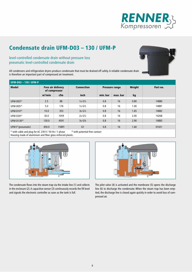
The condensate flows into the steam trap via the intake line (1) and collects in the enclosure (2). A capacitive sensor (3) continuously records the fill level and signals the electronic controller as soon as the tank is full.
The pilot valve (4) is activated and the membrane (5) opens the discharge line (6) to discharge the condensate. When the steam trap has been emp-tied, the discharge line is closed again quickly in order to avoid loss of com-pressed air.
Condensate drain UFM-D03 – 130 / UFM-P level-controlled condensate drain without pressure losspneumatic level-controlled condensate drain
All condensers and refrigeration dryers produce condensate that must be drained off safely. A reliable condensate drain is therefore an important part of compressed air treatment.
6
UFM-D03 – 130 / UFM-P
Model Free air delivery of compressor
Connection Pressure range Weight Part no.
m3/min cfm inch min. bar max. bar kg
UFM-D03(1) 2.5 88 1x G½ 0.8 16 0.80 14880
UFM-D05(2) 5.0 176 1x G½ 0.8 16 1.00 14881
UFM-D10(2) 10.0 353 3x G½ 0.8 16 1.65 14882
UFM-D30(2) 30.0 1059 2x G½ 0.8 16 2.00 14268
UFM-D130(2) 130.0 4591 3x G¾ 0.8 16 2.90 14883
UFM-P (pneumatic) 450.0 15891 G1 0.8 16 1.60 01021(1) with cable and plug for AC 230 V / 50 Hz / 1 phase (2) with potential-free contactHousing made of aluminium and fiber glass enforced plastic.
RF-T / DF-T, 3-in1, with thread
Model Connection Capacity at7 bar
Max. operating pressure
Part no. filter element
Part no.filter complete
inch m³/min cfm bar
RF-T 0050 G½ 0.83 29.3 16 14740 14652
RF-T 0080 G¾ 1.33 46.9 16 14742 14653
RF-T 0110 G1 1.83 64.6 16 14743 14654
DF-T 0050* G½ 0.83 29.3 16 13679 13676
DF-T 0080* G¾ 1.33 46.9 16 13680 13677
DF-T 0110* G1 1.83 64.6 16 13681 13678 * filter elements and housings free from both silicone and release agents Three-stages-filter element being composed of a sub-micro coalescent filter stage, an active carbon filter stage and a high efficient particle filter (air quality class 1 according to ISO8573-1:2010) with differential pressure manometer, economizer incl. condensate float drain.
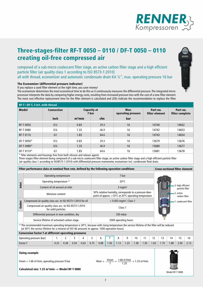
Three-stages-filter RF-T 0050 – 0110 / DF-T 0050 – 0110 creating oil-free compressed air
composed of a sub-micro coalescent filter stage, an active carbon filter stage and a high efficient particle filter (air quality class 1 according to ISO 8573-1:2010) all with thread, economizer and automatic condensate drain KA ½“, max. operating pressure 16 bar
The Economizer (differential pressure indicator)If you replace a used filter element at the right time, you save money! The economizer determines the most economical time to do this as it continuously measures the differential pressure. The integrated micro-processor interprets the data by comparing higher energy costs, resulting from increased pressure loss with the cost of a new filter element. The most cost effective replacement time for the filter element is calculated and LEDs indicate the recommendation to replace the filter.
Filter performance data at nominal flow rate, defined by the following operation conditions Cross-sectional filter element
Inle
t
Operating overpressure 7 bar
Operating temperature (1) 20°C
Content of oil aerosol at inlet 3 mg/m3
Moisture content50% relative humidity, corresponds to a pressure dew-point of approx. +10°C at 20°C operating temperature
Out
let Compressed air quality class acc. to ISO 8573-1:2010 for oil < 0.003 mg/m3, Class 1
Compressed air quality class acc. to ISO 8573-1:2010 for solid particles
Class 1
Differential pressure in new condition, dry 330 mbar
Service lifetime of activated carbon stage 2000 operating hours(1) The recommended maximum operating temperature is 30°C, because with rising temperature the service lifetime of the filter will be reduced (at 30°C the service lifetime for a mineral oil ISO 46 amounts to approx. 1000 operation hours)
Conversion factor f at different operating pressures
Operating pressure (bar) 1 2 3 4 5 6 7 8 9 10 11 12 13 14 15 16
Factor f 0.25 0.38 0.50 0.63 0.75 0.88 1.00 1.13 1.25 1.38 1.50 1.63 1.75 1.88 2.00 2.13
Model RF-T 0080
Vkorr = Vnomf
= 1.66 m3/min1.25
= 1.33 m3/minVnom = 1.66 m3/min, operating pressure 9 bar
Sizing example
Calculated size: 1.33 m3/min –> Model RF-T 0080
3. high efficient particle filter
2. active carbon filter
1. coalescent filter
7
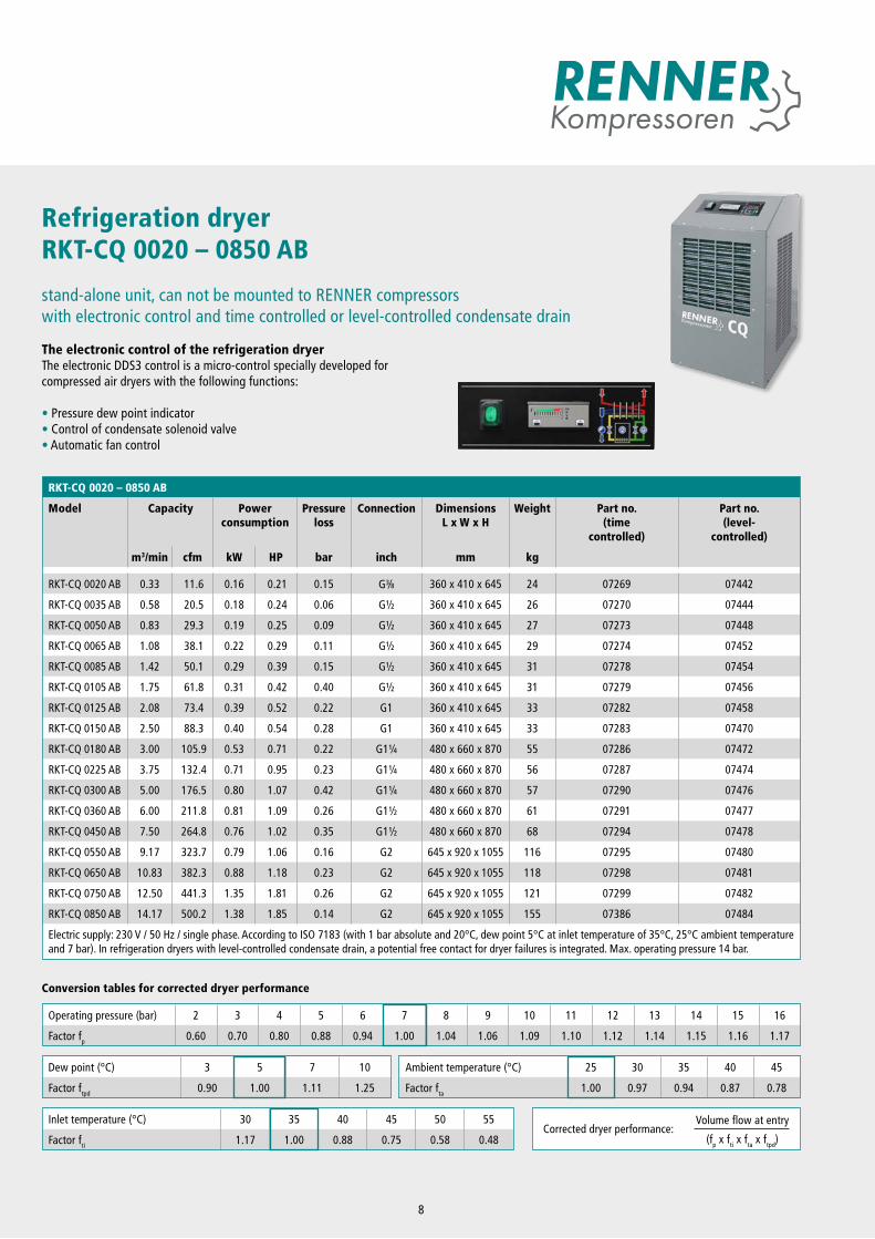
Refrigeration dryer RKT-CQ 0020 – 0850 AB
stand-alone unit, can not be mounted to RENNER compressors with electronic control and time controlled or level-controlled condensate drain
The electronic control of the refrigeration dryerThe electronic DDS3 control is a micro-control specially developed for compressed air dryers with the following functions:
• Pressure dew point indicator• Control of condensate solenoid valve• Automatic fan control
8
RKT-CQ 0020 – 0850 AB
Model Capacity Powerconsumption
Pressureloss
Connection DimensionsL x W x H
Weight Part no.(time
controlled)
Part no.(level-
controlled)
m3/min cfm kW HP bar inch mm kg
RKT-CQ 0020 AB 0.33 11.6 0.16 0.21 0.15 G3 8 360 x 410 x 645 24 07269 07442
RKT-CQ 0035 AB 0.58 20.5 0.18 0.24 0.06 G½ 360 x 410 x 645 26 07270 07444
RKT-CQ 0050 AB 0.83 29.3 0.19 0.25 0.09 G½ 360 x 410 x 645 27 07273 07448
RKT-CQ 0065 AB 1.08 38.1 0.22 0.29 0.11 G½ 360 x 410 x 645 29 07274 07452
RKT-CQ 0085 AB 1.42 50.1 0.29 0.39 0.15 G½ 360 x 410 x 645 31 07278 07454
RKT-CQ 0105 AB 1.75 61.8 0.31 0.42 0.40 G½ 360 x 410 x 645 31 07279 07456
RKT-CQ 0125 AB 2.08 73.4 0.39 0.52 0.22 G1 360 x 410 x 645 33 07282 07458
RKT-CQ 0150 AB 2.50 88.3 0.40 0.54 0.28 G1 360 x 410 x 645 33 07283 07470
RKT-CQ 0180 AB 3.00 105.9 0.53 0.71 0.22 G1¼ 480 x 660 x 870 55 07286 07472
RKT-CQ 0225 AB 3.75 132.4 0.71 0.95 0.23 G1¼ 480 x 660 x 870 56 07287 07474
RKT-CQ 0300 AB 5.00 176.5 0.80 1.07 0.42 G1¼ 480 x 660 x 870 57 07290 07476
RKT-CQ 0360 AB 6.00 211.8 0.81 1.09 0.26 G1½ 480 x 660 x 870 61 07291 07477
RKT-CQ 0450 AB 7.50 264.8 0.76 1.02 0.35 G1½ 480 x 660 x 870 68 07294 07478
RKT-CQ 0550 AB 9.17 323.7 0.79 1.06 0.16 G2 645 x 920 x 1055 116 07295 07480
RKT-CQ 0650 AB 10.83 382.3 0.88 1.18 0.23 G2 645 x 920 x 1055 118 07298 07481
RKT-CQ 0750 AB 12.50 441.3 1.35 1.81 0.26 G2 645 x 920 x 1055 121 07299 07482
RKT-CQ 0850 AB 14.17 500.2 1.38 1.85 0.14 G2 645 x 920 x 1055 155 07386 07484
Electric supply: 230 V / 50 Hz / single phase. According to ISO 7183 (with 1 bar absolute and 20°C, dew point 5°C at inlet temperature of 35°C, 25°C ambient temperature and 7 bar). In refrigeration dryers with level-controlled condensate drain, a potential free contact for dryer failures is integrated. Max. operating pressure 14 bar.
Inlet temperature (°C) 30 35 40 45 50 55
Factor fti 1.17 1.00 0.88 0.75 0.58 0.48Corrected dryer performance:
Volume flow at entry
(fp x fti x fta x ftpd)
Dew point (°C) 3 5 7 10
Factor ftpd 0.90 1.00 1.11 1.25
Ambient temperature (°C) 25 30 35 40 45
Factor fta 1.00 0.97 0.94 0.87 0.78
Operating pressure (bar) 2 3 4 5 6 7 8 9 10 11 12 13 14 15 16
Factor fp 0.60 0.70 0.80 0.88 0.94 1.00 1.04 1.06 1.09 1.10 1.12 1.14 1.15 1.16 1.17
Conversion tables for corrected dryer performance
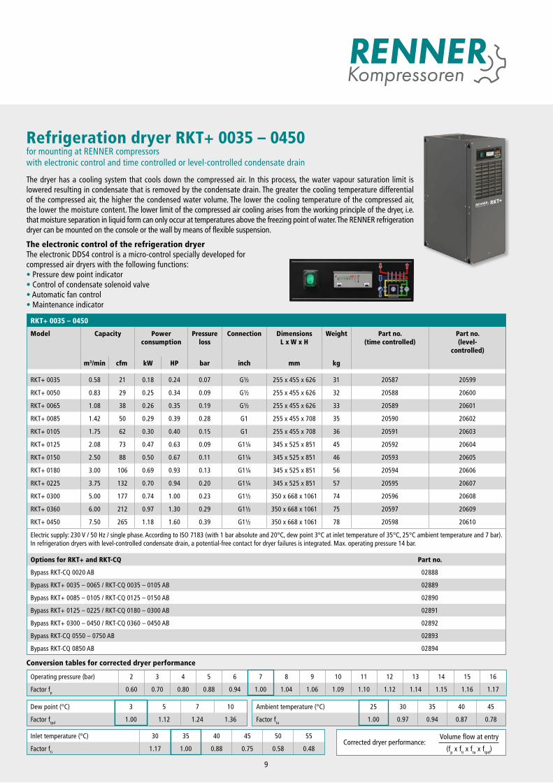
Refrigeration dryer RKT+ 0035 – 0450for mounting at RENNER compressorswith electronic control and time controlled or level-controlled condensate drain
The dryer has a cooling system that cools down the compressed air. In this process, the water vapour saturation limit is lowered resulting in condensate that is removed by the condensate drain. The greater the cooling temperature differential of the compressed air, the higher the condensed water volume. The lower the cooling temperature of the compressed air, the lower the moisture content. The lower limit of the compressed air cooling arises from the working principle of the dryer, i.e. that moisture separation in liquid form can only occur at temperatures above the freezing point of water. The RENNER refrigeration dryer can be mounted on the console or the wall by means of flexible suspension.
The electronic control of the refrigeration dryerThe electronic DDS4 control is a micro-control specially developed for compressed air dryers with the following functions:• Pressure dew point indicator• Control of condensate solenoid valve• Automatic fan control• Maintenance indicator
9
RKT+ 0035 – 0450
Model Capacity Powerconsumption
Pressureloss
Connection DimensionsL x W x H
Weight Part no.(time controlled)
Part no.(level-
controlled)
m3/min cfm kW HP bar inch mm kg
RKT+ 0035 0.58 21 0.18 0.24 0.07 G½ 255 x 455 x 626 31 20587 20599
RKT+ 0050 0.83 29 0.25 0.34 0.09 G½ 255 x 455 x 626 32 20588 20600
RKT+ 0065 1.08 38 0.26 0.35 0.19 G½ 255 x 455 x 626 33 20589 20601
RKT+ 0085 1.42 50 0.29 0.39 0.28 G1 255 x 455 x 708 35 20590 20602
RKT+ 0105 1.75 62 0.30 0.40 0.15 G1 255 x 455 x 708 36 20591 20603
RKT+ 0125 2.08 73 0.47 0.63 0.09 G1¼ 345 x 525 x 851 45 20592 20604
RKT+ 0150 2.50 88 0.50 0.67 0.11 G1¼ 345 x 525 x 851 46 20593 20605
RKT+ 0180 3.00 106 0.69 0.93 0.13 G1¼ 345 x 525 x 851 56 20594 20606
RKT+ 0225 3.75 132 0.70 0.94 0.20 G1¼ 345 x 525 x 851 57 20595 20607
RKT+ 0300 5.00 177 0.74 1.00 0.23 G1½ 350 x 668 x 1061 74 20596 20608
RKT+ 0360 6.00 212 0.97 1.30 0.29 G1½ 350 x 668 x 1061 75 20597 20609
RKT+ 0450 7.50 265 1.18 1.60 0.39 G1½ 350 x 668 x 1061 78 20598 20610
Electric supply: 230 V / 50 Hz / single phase. According to ISO 7183 (with 1 bar absolute and 20°C, dew point 3°C at inlet temperature of 35°C, 25°C ambient temperature and 7 bar). In refrigeration dryers with level-controlled condensate drain, a potential-free contact for dryer failures is integrated. Max. operating pressure 14 bar.
Options for RKT+ and RKT-CQ Part no.
Bypass RKT-CQ 0020 AB 02888
Bypass RKT+ 0035 – 0065 / RKT-CQ 0035 – 0105 AB 02889
Bypass RKT+ 0085 – 0105 / RKT-CQ 0125 – 0150 AB 02890
Bypass RKT+ 0125 – 0225 / RKT-CQ 0180 – 0300 AB 02891
Bypass RKT+ 0300 – 0450 / RKT-CQ 0360 – 0450 AB 02892
Bypass RKT-CQ 0550 – 0750 AB 02893
Bypass RKT-CQ 0850 AB 02894
Conversion tables for corrected dryer performance
Operating pressure (bar) 2 3 4 5 6 7 8 9 10 11 12 13 14 15 16
Factor fp 0.60 0.70 0.80 0.88 0.94 1.00 1.04 1.06 1.09 1.10 1.12 1.14 1.15 1.16 1.17
Inlet temperature (°C) 30 35 40 45 50 55
Factor fti 1.17 1.00 0.88 0.75 0.58 0.48Corrected dryer performance:
Volume flow at entry
(fp x fti x fta x ftpd)
Dew point (°C) 3 5 7 10
Factor ftpd 1.00 1.12 1.24 1.36
Ambient temperature (°C) 25 30 35 40 45
Factor fta 1.00 0.97 0.94 0.87 0.78
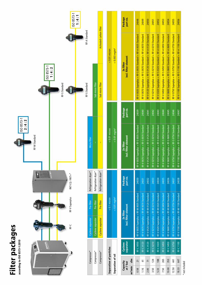
Filt
er p
acka
ges
acco
rdin
g to
ISO
857
3-1:
2010
Sepa
rati
on o
f pa
rtic
les
< 0
.1 m
icro
n<
0.0
1 m
icro
n<
0.0
1 m
icro
n
Sepa
rati
on o
f oi
l<
0.0
1 m
g/m
³<
0.0
1 m
g/m
³<
0.0
03 m
g/m
³
Capa
city
at
7 b
arCy
clon
e se
para
tor
2x f
ilter
in
cl. f
ilter
ele
men
tPa
ckag
e pa
rt n
o.2x
filt
er
incl
. filt
er e
lem
ent
Pack
age
part
no.
3x f
ilter
in
cl. f
ilter
ele
men
tPa
ckag
e pa
rt n
o.
m3 /m
incf
m
0.58
21RF
-C 0
050
RF-V
003
5 Su
perp
lus
+ R
F-M
003
5 St
anda
rd24
030
RF-V
003
5 Su
perp
lus +
RF-
S 00
35 S
tand
ard
2403
9RF
-V 0
035
Supe
rplu
s +
RF-
S 00
35 S
tand
ard
+ R
F-A
0035
Sta
ndar
d24
048
1.16
41RF
-C 0
120
RF-V
007
0 Su
perp
lus
+ R
F-M
007
0 St
anda
rd24
031
RF-V
007
0 Su
perp
lus +
RF-
S 00
70 S
tand
ard
2404
0RF
-V 0
070
Supe
rplu
s +
RF-
S 00
70 S
tand
ard
+ R
F-A
0070
Sta
ndar
d24
049
2.00
71RF
-C 0
120
RF-V
012
0 Su
perp
lus
+ R
F-M
012
0 St
anda
rd24
032
RF-V
012
0 Su
perp
lus +
RF-
S 01
20 S
tand
ard
2404
1RF
-V 0
120
Supe
rplu
s +
RF-
S 01
20 S
tand
ard
+ R
F-A
0120
Sta
ndar
d24
050
3.50
124
RF-C
021
0RF
-V 0
210
Supe
rplu
s +
RF-
M 0
210
Stan
dard
2403
3RF
-V 0
210
Supe
rplu
s + R
F-S
0210
Sta
ndar
d24
042
RF-V
021
0 Su
perp
lus
+ R
F-S
0210
Sta
ndar
d +
RF-
A 02
10 S
tand
ard
2405
1
5.33
188
RF-C
032
0RF
-V 0
320
Supe
rplu
s +
RF-
M 0
320
Stan
dard
2403
4RF
-V 0
320
Supe
rplu
s + R
F-S
0320
Sta
ndar
d24
043
RF-V
032
0 Su
perp
lus
+ R
F-S
0320
Sta
ndar
d +
RF-
A 03
20 S
tand
ard
2405
2
7.50
265
RF-C
045
0RF
-V 0
450
Supe
rplu
s +
RF-
M 0
450
Stan
dard
2403
5RF
-V 0
450
Supe
rplu
s + R
F-S
0450
Sta
ndar
d24
044
RF-V
045
0 Su
perp
lus
+ R
F-S
0450
Sta
ndar
d +
RF-
A 04
50 S
tand
ard
2405
3
10.0
035
3RF
-C 0
450
RF-V
060
0 Su
perp
lus
+ R
F-M
060
0 St
anda
rd24
036
RF-V
060
0 Su
perp
lus +
RF-
S 06
00 S
tand
ard
2404
5RF
-V 0
600
Supe
rplu
s +
RF-
S 06
00 S
tand
ard
+ R
F-A
0600
Sta
ndar
d24
054
12.5
044
1RF
-C 0
750
RF-V
075
0 Su
perp
lus
+ R
F-M
075
0 St
anda
rd24
037
RF-V
075
0 Su
perp
lus +
RF-
S 07
50 S
tand
ard
2404
6RF
-V 0
750
Supe
rplu
s +
RF-
S 07
50 S
tand
ard
+ R
F-A
0750
Sta
ndar
d24
055
18.3
364
7RF
-C 1
100
RF-V
110
0 Su
perp
lus
+ R
F-M
110
0 St
anda
rd24
038
RF-V
110
0 Su
perp
lus +
RF-
S 11
00 S
tand
ard
2404
7RF
-V 1
100
Supe
rplu
s +
RF-
S 11
00 S
tand
ard
+ R
F-A
1100
Sta
ndar
d24
056
Com
pres
sor*
Cycl
one
sepa
rato
rPr
e-fil
ter
Refri
gera
tion
drye
r*M
icro
filte
r
Com
pres
sor*
Cycl
one
sepa
rato
rPr
e-fil
ter
Refri
gera
tion
drye
r*–
Sub
mic
ro fi
lter
Com
pres
sor*
Cycl
one
sepa
rato
rPr
e-fil
ter
Refri
gera
tion
drye
r*–
Sub
mic
ro fi
lter
Activ
ated
car
bon
filte
r
* not
incl
uded
ISO
857
3-1
1 : 4
: 2
RF-S
Sta
ndar
d
ISO
857
3-1
1 : 4
: 1
RF-V
Sup
erpl
usRF
-C
RF-S
Sta
ndar
dRF
-A S
tand
ard
ISO
857
3-1
2 : 4
: 2
RF-M
Sta
ndar
d
RKT-
CQ /
RKT+
*
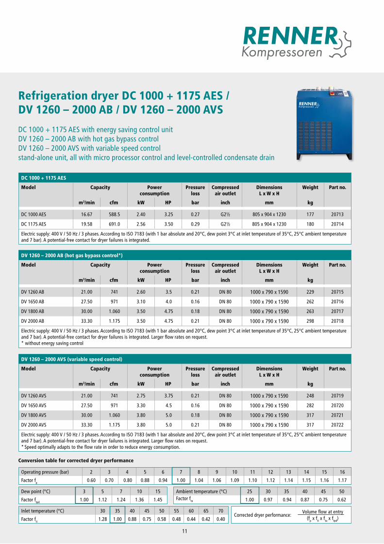
Refrigeration dryer DC 1000 + 1175 AES / DV 1260 – 2000 AB / DV 1260 – 2000 AVS
DC 1000 + 1175 AES with energy saving control unitDV 1260 – 2000 AB with hot gas bypass controlDV 1260 – 2000 AVS with variable speed controlstand-alone unit, all with micro processor control and level-controlled condensate drain
DV 1260 – 2000 AB (hot gas bypass control*)
Model Capacity Power consumption
Pressure loss
Compressed air outlet
DimensionsL x W x H
Weight Part no.
m3/min cfm kW HP bar inch mm kg
DV 1260 AB 21.00 741 2.60 3.5 0.21 DN 80 1000 x 790 x 1590 229 20715
DV 1650 AB 27.50 971 3.10 4.0 0.16 DN 80 1000 x 790 x 1590 262 20716
DV 1800 AB 30.00 1.060 3.50 4.75 0.18 DN 80 1000 x 790 x 1590 263 20717
DV 2000 AB 33.30 1.175 3.50 4.75 0.21 DN 80 1000 x 790 x 1590 298 20718
Electric supply: 400 V / 50 Hz / 3 phases. According to ISO 7183 (with 1 bar absolute and 20°C, dew point 3°C at inlet temperature of 35°C, 25°C ambient temperature and 7 bar). A potential-free contact for dryer failures is integrated. Larger flow rates on request. * without energy saving control
Operating pressure (bar) 2 3 4 5 6 7 8 9 10 11 12 13 14 15 16
Factor fp 0.60 0.70 0.80 0.88 0.94 1.00 1.04 1.06 1.09 1.10 1.12 1.14 1.15 1.16 1.17
Dew point (°C) 3 5 7 10 15
Factor ftpd 1.00 1.12 1.24 1.36 1.45
Ambient temperature (°C) 25 30 35 40 45 50Factor fta 1.00 0.97 0.94 0.87 0.75 0.62
Inlet temperature (°C) 30 35 40 45 50 55 60 65 70
Factor fti 1.28 1.00 0.88 0.75 0.58 0.48 0.44 0.42 0.40Corrected dryer performance:
Volume flow at entry(fp x fti x fta x ftpd)
Conversion table for corrected dryer performance
DC 1000 + 1175 AES
Model Capacity Power consumption
Pressure loss
Compressed air outlet
DimensionsL x W x H
Weight Part no.
m3/min cfm kW HP bar inch mm kg
DC 1000 AES 16.67 588.5 2.40 3.25 0.27 G2½ 805 x 904 x 1230 177 20713
DC 1175 AES 19.58 691.0 2.56 3.50 0.29 G2½ 805 x 904 x 1230 180 20714
Electric supply: 400 V / 50 Hz / 3 phases. According to ISO 7183 (with 1 bar absolute and 20°C, dew point 3°C at inlet temperature of 35°C, 25°C ambient temperature and 7 bar). A potential-free contact for dryer failures is integrated.
DV 1260 – 2000 AVS (variable speed control)
Model Capacity Power consumption
Pressure loss
Compressed air outlet
DimensionsL x W x H
Weight Part no.
m3/min cfm kW HP bar inch mm kg
DV 1260 AVS 21.00 741 2.75 3.75 0.21 DN 80 1000 x 790 x 1590 248 20719
DV 1650 AVS 27.50 971 3.30 4.5 0.16 DN 80 1000 x 790 x 1590 282 20720
DV 1800 AVS 30.00 1.060 3.80 5.0 0.18 DN 80 1000 x 790 x 1590 317 20721
DV 2000 AVS 33.30 1.175 3.80 5.0 0.21 DN 80 1000 x 790 x 1590 317 20722
Electric supply: 400 V / 50 Hz / 3 phases. According to ISO 7183 (with 1 bar absolute and 20°C, dew point 3°C at inlet temperature of 35°C, 25°C ambient temperature and 7 bar). A potential-free contact for dryer failures is integrated. Larger flow rates on request.* Speed optimally adapts to the flow rate in order to reduce energy consumption.
11
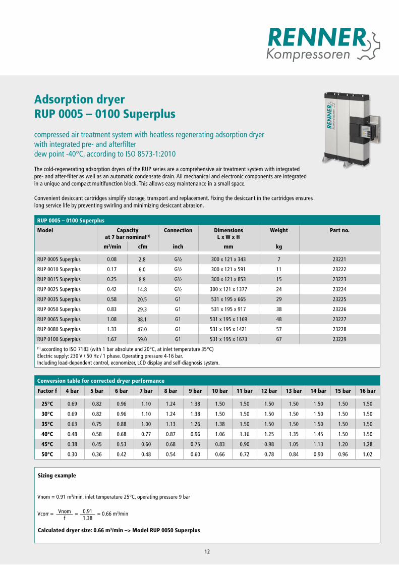
Adsorption dryerRUP 0005 – 0100 Superplus
compressed air treatment system with heatless regenerating adsorption dryerwith integrated pre- and afterfilterdew point -40°C, according to ISO 8573-1:2010
The cold-regenerating adsorption dryers of the RUP series are a comprehensive air treatment system with integrated pre- and after-filter as well as an automatic condensate drain. All mechanical and electronic components are integrated in a unique and compact multifunction block. This allows easy maintenance in a small space.
Convenient desiccant cartridges simplify storage, transport and replacement. Fixing the desiccant in the cartridges ensures long service life by preventing swirling and minimizing desiccant abrasion.
12
Conversion table for corrected dryer performance
Factor f 4 bar 5 bar 6 bar 7 bar 8 bar 9 bar 10 bar 11 bar 12 bar 13 bar 14 bar 15 bar 16 bar
25°C 0.69 0.82 0.96 1.10 1.24 1.38 1.50 1.50 1.50 1.50 1.50 1.50 1.50
30°C 0.69 0.82 0.96 1.10 1.24 1.38 1.50 1.50 1.50 1.50 1.50 1.50 1.50
35°C 0.63 0.75 0.88 1.00 1.13 1.26 1.38 1.50 1.50 1.50 1.50 1.50 1.50
40°C 0.48 0.58 0.68 0.77 0.87 0.96 1.06 1.16 1.25 1.35 1.45 1.50 1.50
45°C 0.38 0.45 0.53 0.60 0.68 0.75 0.83 0.90 0.98 1.05 1.13 1.20 1.28
50°C 0.30 0.36 0.42 0.48 0.54 0.60 0.66 0.72 0.78 0.84 0.90 0.96 1.02
RUP 0005 – 0100 Superplus
Model Capacity at 7 bar nominal(1)
Connection Dimensions L x W x H
Weight Part no.
m3/min cfm inch mm kg
RUP 0005 Superplus 0.08 2.8 G½ 300 x 121 x 343 7 23221
RUP 0010 Superplus 0.17 6.0 G½ 300 x 121 x 591 11 23222
RUP 0015 Superplus 0.25 8.8 G½ 300 x 121 x 853 15 23223
RUP 0025 Superplus 0.42 14.8 G½ 300 x 121 x 1377 24 23224
RUP 0035 Superplus 0.58 20.5 G1 531 x 195 x 665 29 23225
RUP 0050 Superplus 0.83 29.3 G1 531 x 195 x 917 38 23226
RUP 0065 Superplus 1.08 38.1 G1 531 x 195 x 1169 48 23227
RUP 0080 Superplus 1.33 47.0 G1 531 x 195 x 1421 57 23228
RUP 0100 Superplus 1.67 59.0 G1 531 x 195 x 1673 67 23229(1) according to ISO 7183 (with 1 bar absolute and 20°C, at inlet temperature 35°C)Electric supply: 230 V / 50 Hz / 1 phase. Operating pressure 4-16 bar.Including load-dependent control, economizer, LCD display and self-diagnosis system.
Sizing example
Calculated dryer size: 0.66 m3/min –> Model RUP 0050 Superplus
Vcorr = Vnomf
= 0.911.38
= 0.66 m3/min
Vnom = 0.91 m3/min, inlet temperature 25°C, operating pressure 9 bar
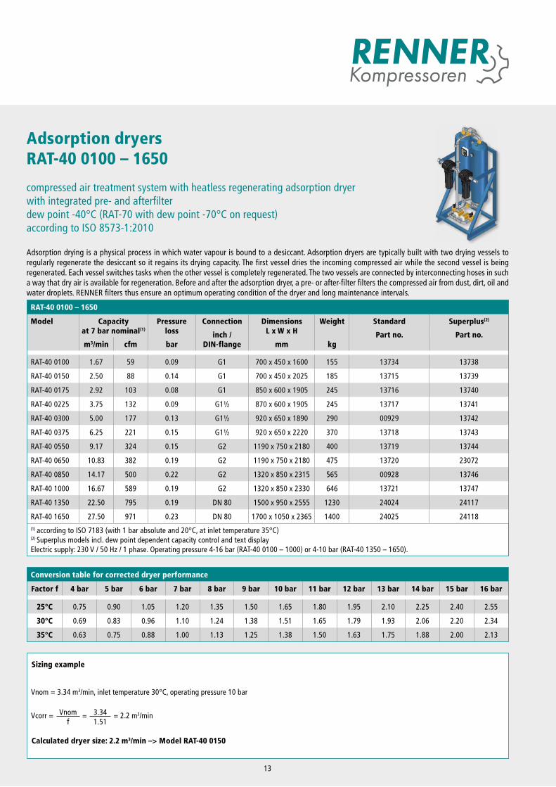
Adsorption dryersRAT-40 0100 – 1650
compressed air treatment system with heatless regenerating adsorption dryerwith integrated pre- and afterfilterdew point -40°C (RAT-70 with dew point -70°C on request)according to ISO 8573-1:2010
Adsorption drying is a physical process in which water vapour is bound to a desiccant. Adsorption dryers are typically built with two drying vessels to regularly regenerate the desiccant so it regains its drying capacity. The first vessel dries the incoming compressed air while the second vessel is being regenerated. Each vessel switches tasks when the other vessel is completely regenerated. The two vessels are connected by interconnecting hoses in such a way that dry air is available for regeneration. Before and after the adsorption dryer, a pre- or after-filter filters the compressed air from dust, dirt, oil and water droplets. RENNER filters thus ensure an optimum operating condition of the dryer and long maintenance intervals.
RAT-40 0100 – 1650
Model Capacity at 7 bar nominal(1)
Pressureloss
Connection Dimensions L x W x H
Weight Standard Superplus(2)
inch / DIN-flange
Part no. Part no.m3/min cfm bar mm kg
RAT-40 0100 1.67 59 0.09 G1 700 x 450 x 1600 155 13734 13738
RAT-40 0150 2.50 88 0.14 G1 700 x 450 x 2025 185 13715 13739
RAT-40 0175 2.92 103 0.08 G1 850 x 600 x 1905 245 13716 13740
RAT-40 0225 3.75 132 0.09 G1½ 870 x 600 x 1905 245 13717 13741
RAT-40 0300 5.00 177 0.13 G1½ 920 x 650 x 1890 290 00929 13742
RAT-40 0375 6.25 221 0.15 G1½ 920 x 650 x 2220 370 13718 13743
RAT-40 0550 9.17 324 0.15 G2 1190 x 750 x 2180 400 13719 13744
RAT-40 0650 10.83 382 0.19 G2 1190 x 750 x 2180 475 13720 23072
RAT-40 0850 14.17 500 0.22 G2 1320 x 850 x 2315 565 00928 13746
RAT-40 1000 16.67 589 0.19 G2 1320 x 850 x 2330 646 13721 13747
RAT-40 1350 22.50 795 0.19 DN 80 1500 x 950 x 2555 1230 24024 24117
RAT-40 1650 27.50 971 0.23 DN 80 1700 x 1050 x 2365 1400 24025 24118(1) according to ISO 7183 (with 1 bar absolute and 20°C, at inlet temperature 35°C)(2) Superplus models incl. dew point dependent capacity control and text displayElectric supply: 230 V / 50 Hz / 1 phase. Operating pressure 4-16 bar (RAT-40 0100 – 1000) or 4-10 bar (RAT-40 1350 – 1650).
Sizing example
Calculated dryer size: 2.2 m3/min –> Model RAT-40 0150
Vcorr = Vnomf
= 3.341.51
= 2.2 m3/min
Vnom = 3.34 m3/min, inlet temperature 30°C, operating pressure 10 bar
Conversion table for corrected dryer performance
Factor f 4 bar 5 bar 6 bar 7 bar 8 bar 9 bar 10 bar 11 bar 12 bar 13 bar 14 bar 15 bar 16 bar
25°C 0.75 0.90 1.05 1.20 1.35 1.50 1.65 1.80 1.95 2.10 2.25 2.40 2.55
30°C 0.69 0.83 0.96 1.10 1.24 1.38 1.51 1.65 1.79 1.93 2.06 2.20 2.34
35°C 0.63 0.75 0.88 1.00 1.13 1.25 1.38 1.50 1.63 1.75 1.88 2.00 2.13
13
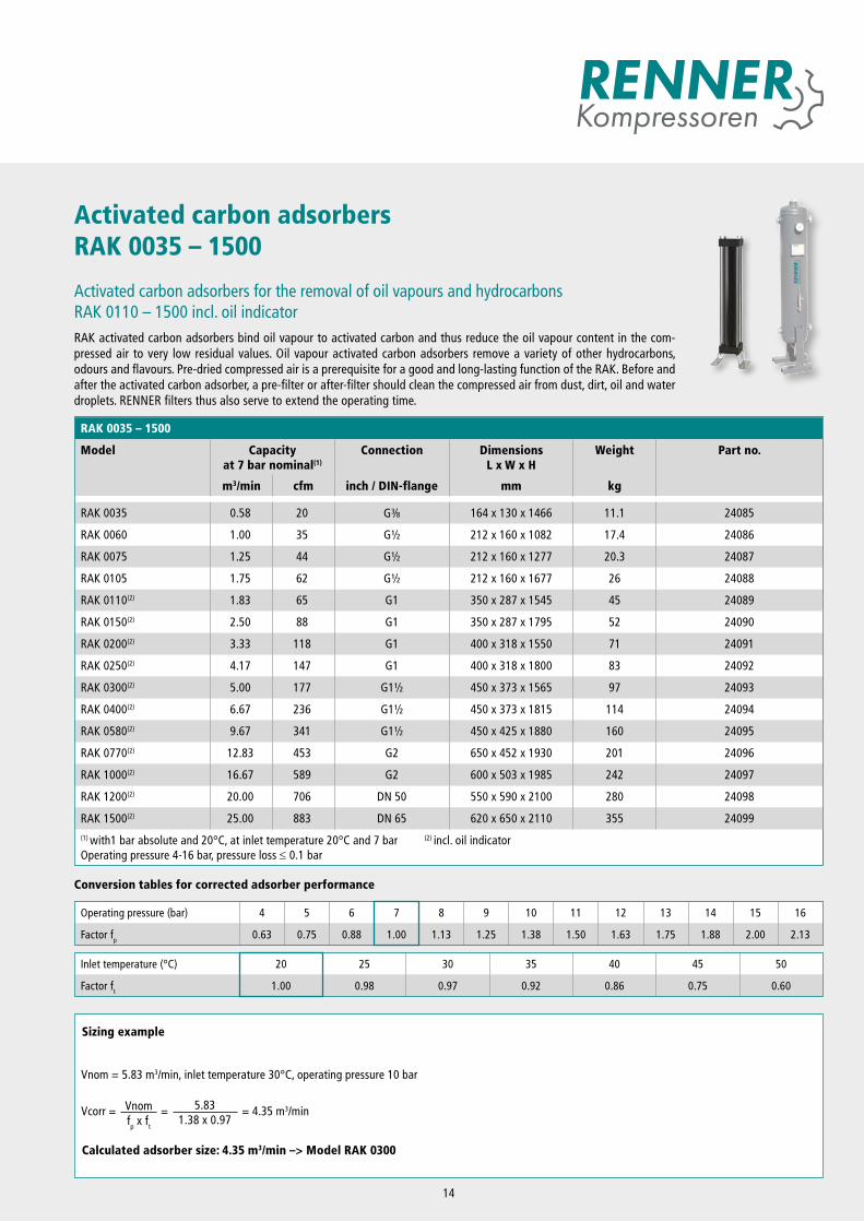
Activated carbon adsorbersRAK 0035 – 1500
Activated carbon adsorbers for the removal of oil vapours and hydrocarbonsRAK 0110 – 1500 incl. oil indicatorRAK activated carbon adsorbers bind oil vapour to activated carbon and thus reduce the oil vapour content in the com-pressed air to very low residual values. Oil vapour activated carbon adsorbers remove a variety of other hydrocarbons, odours and flavours. Pre-dried compressed air is a prerequisite for a good and long-lasting function of the RAK. Before and after the activated carbon adsorber, a pre-filter or after-filter should clean the compressed air from dust, dirt, oil and water droplets. RENNER filters thus also serve to extend the operating time.
RAK 0035 – 1500
Model Capacity at 7 bar nominal(1)
Connection Dimensions L x W x H
Weight Part no.
m3/min cfm inch / DIN-flange mm kg
RAK 0035 0.58 20 G3 8 164 x 130 x 1466 11.1 24085
RAK 0060 1.00 35 G½ 212 x 160 x 1082 17.4 24086
RAK 0075 1.25 44 G½ 212 x 160 x 1277 20.3 24087
RAK 0105 1.75 62 G½ 212 x 160 x 1677 26 24088
RAK 0110(2) 1.83 65 G1 350 x 287 x 1545 45 24089
RAK 0150(2) 2.50 88 G1 350 x 287 x 1795 52 24090
RAK 0200(2) 3.33 118 G1 400 x 318 x 1550 71 24091
RAK 0250(2) 4.17 147 G1 400 x 318 x 1800 83 24092
RAK 0300(2) 5.00 177 G1½ 450 x 373 x 1565 97 24093
RAK 0400(2) 6.67 236 G1½ 450 x 373 x 1815 114 24094
RAK 0580(2) 9.67 341 G1½ 450 x 425 x 1880 160 24095
RAK 0770(2) 12.83 453 G2 650 x 452 x 1930 201 24096
RAK 1000(2) 16.67 589 G2 600 x 503 x 1985 242 24097
RAK 1200(2) 20.00 706 DN 50 550 x 590 x 2100 280 24098
RAK 1500(2) 25.00 883 DN 65 620 x 650 x 2110 355 24099(1) with1 bar absolute and 20°C, at inlet temperature 20°C and 7 bar (2) incl. oil indicatorOperating pressure 4-16 bar, pressure loss ≤ 0.1 bar
Sizing example
Calculated adsorber size: 4.35 m3/min –> Model RAK 0300
Vnom = 5.83 m3/min, inlet temperature 30°C, operating pressure 10 bar
Vnomfp x ft
= 5.831.38 x 0.97
= 4.35 m3/minVcorr =
Conversion tables for corrected adsorber performance
Operating pressure (bar) 4 5 6 7 8 9 10 11 12 13 14 15 16
Factor fp 0.63 0.75 0.88 1.00 1.13 1.25 1.38 1.50 1.63 1.75 1.88 2.00 2.13
Inlet temperature (°C) 20 25 30 35 40 45 50
Factor ft 1.00 0.98 0.97 0.92 0.86 0.75 0.60
14
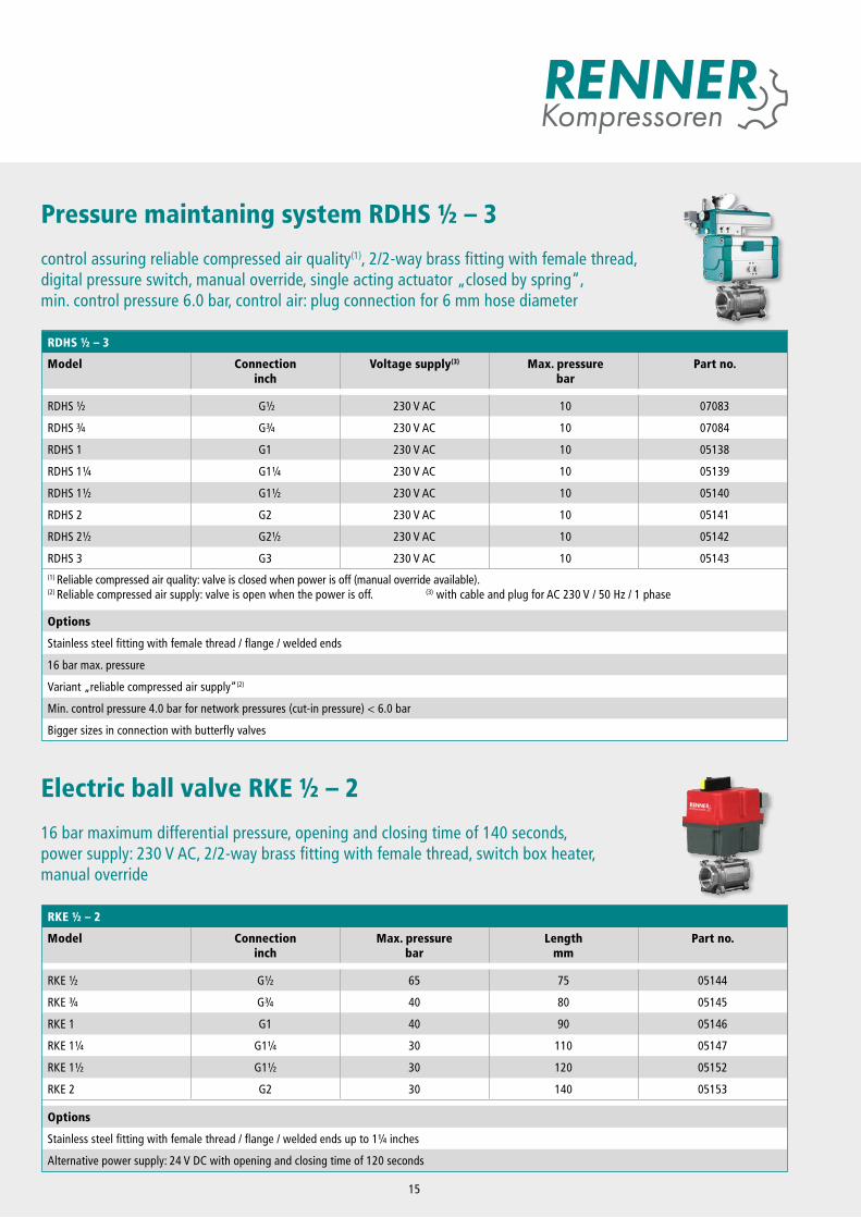
Pressure maintaning system RDHS ½ – 3
control assuring reliable compressed air quality(1), 2/2-way brass fitting with female thread, digital pressure switch, manual override, single acting actuator „closed by spring“, min. control pressure 6.0 bar, control air: plug connection for 6 mm hose diameter
RKE ½ – 2
Model Connectioninch
Max. pressurebar
Lengthmm
Part no.
RKE ½ G½ 65 75 05144
RKE ¾ G¾ 40 80 05145
RKE 1 G1 40 90 05146
RKE 1¼ G1¼ 30 110 05147
RKE 1½ G1½ 30 120 05152
RKE 2 G2 30 140 05153
Options
Stainless steel fitting with female thread / flange / welded ends up to 1¼ inches
Alternative power supply: 24 V DC with opening and closing time of 120 seconds
Electric ball valve RKE ½ – 2
16 bar maximum differential pressure, opening and closing time of 140 seconds, power supply: 230 V AC, 2/2-way brass fitting with female thread, switch box heater, manual override
RDHS ½ – 3
Model Connectioninch
Voltage supply(3) Max. pressurebar
Part no.
RDHS ½ G½ 230 V AC 10 07083
RDHS ¾ G¾ 230 V AC 10 07084
RDHS 1 G1 230 V AC 10 05138
RDHS 1¼ G1¼ 230 V AC 10 05139
RDHS 1½ G1½ 230 V AC 10 05140
RDHS 2 G2 230 V AC 10 05141
RDHS 2½ G2½ 230 V AC 10 05142
RDHS 3 G3 230 V AC 10 05143(1) Reliable compressed air quality: valve is closed when power is off (manual override available). (2) Reliable compressed air supply: valve is open when the power is off. (3) with cable and plug for AC 230 V / 50 Hz / 1 phase
Options
Stainless steel fitting with female thread / flange / welded ends
16 bar max. pressure
Variant „reliable compressed air supply“(2)
Min. control pressure 4.0 bar for network pressures (cut-in pressure) < 6.0 bar
Bigger sizes in connection with butterfly valves
15
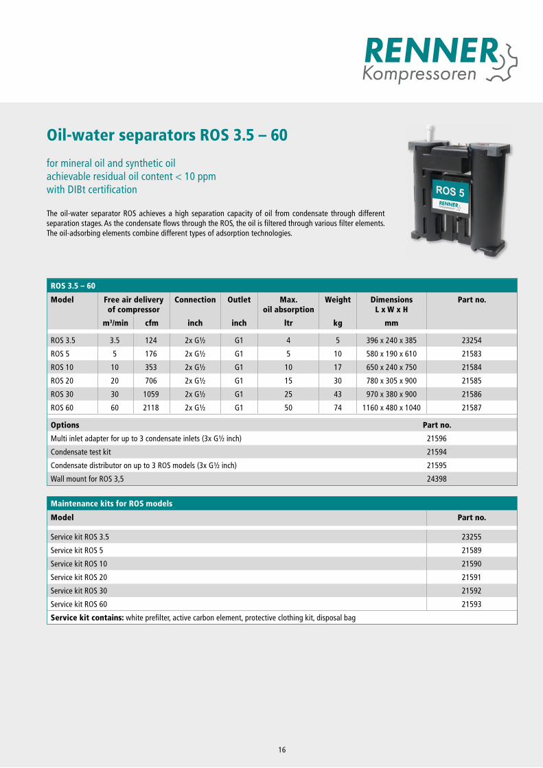
Oil-water separators ROS 3.5 – 60
for mineral oil and synthetic oilachievable residual oil content < 10 ppmwith DIBt certification
The oil-water separator ROS achieves a high separation capacity of oil from condensate through different separation stages. As the condensate flows through the ROS, the oil is filtered through various filter elements. The oil-adsorbing elements combine different types of adsorption technologies.
16
Maintenance kits for ROS models
Model Part no.
Service kit ROS 3.5 23255
Service kit ROS 5 21589
Service kit ROS 10 21590
Service kit ROS 20 21591
Service kit ROS 30 21592
Service kit ROS 60 21593
Service kit contains: white prefilter, active carbon element, protective clothing kit, disposal bag
ROS 3.5 – 60
Model Free air delivery of compressor
Connection Outlet Max. oil absorption
Weight DimensionsL x W x H
Part no.
m3/min cfm inch inch ltr kg mm
ROS 3.5 3.5 124 2x G½ G1 4 5 396 x 240 x 385 23254
ROS 5 5 176 2x G½ G1 5 10 580 x 190 x 610 21583
ROS 10 10 353 2x G½ G1 10 17 650 x 240 x 750 21584
ROS 20 20 706 2x G½ G1 15 30 780 x 305 x 900 21585
ROS 30 30 1059 2x G½ G1 25 43 970 x 380 x 900 21586
ROS 60 60 2118 2x G½ G1 50 74 1160 x 480 x 1040 21587
Options Part no.
Multi inlet adapter for up to 3 condensate inlets (3x G½ inch) 21596
Condensate test kit 21594
Condensate distributor on up to 3 ROS models (3x G½ inch) 21595
Wall mount for ROS 3,5 24398
RENNER GmbH ∙ Kompressoren
Emil-Weber-Strasse 32 D-74363 Gueglingen
Phone +49 (0) 7135 93193-0 Fax +49 (0) 7135 93193-50
E-Mail: [email protected] www.renner-kompressoren.de
Your RENNER distributor:
COMPRESSED AIR FOR ALL APPLICATIONS
RENNER GmbH Kompressoren, a family run business established in 1994, develops and assembles economical and energy-efficient compressors. A broad range of compressed air accessories are also part of the product portfolio. The structure and size of the company ensure flexible decisions and short lead times, thus providing optimal focus on the requirements of the customers.
THE RENNER MANUFACTURING AND SUPPLY PROGRAMME:We can supply you with the right compressor for any application – guaranteed.
SCREW COMPRESSORS:• From 2.2 to 355 kW• Up to 40 bar, e.g. for manufacture of PET bottles• Compact systems with air receiver, refrigeration dryer,
and variable speed control• Heat exchanger integrated or as an external box• Special applications: gas compression, operation of
drilling devices, rail, and special-purpose vehicles• Customized models designed to customer specifications
OIL-FREE COMPRESSORS:• SCROLL compressors for oil-free compressed air from 1.5 to 30.0 kW• Water-injected screw compressors for oil-free compressed air
in breathing air quality from 18.5 to 120 kW
PISTON COMPRESSORS:• From 1.5 to 11.0 kW• Stationary or mobile, with or without sound insulation
CONTROL SYSTEMS:• Compressor control systems• Superordinate control systems• State-of-the-art web server monitoring ndustry 4.0
COMPRESSED AIR ACCESSORIES:• Air filters, air receivers, refrigeration dryers, adsorption dryers,
condensate drains, and oil-water-separatorsAu
fber
eitu
ng -
EN -
03/2
020