Embed Size (px)
Citation preview
10(2013) 797 – 811
Abstract This work suggests a computational model that takes account of effective fibers on toughening in FRC at an early stage of crack formation. We derived the distribution of pressure provoked by a random inclined fiber in the matrix and calculated stresses through integrating the pressure and tangent stress along the fiber/matrix interface with the Kelvin’s fundamental solution and the Mindlin’s complementary solution. The evolution of spalling in the matrix was traced. The percentages of effective fibers were evaluated with variations in strength, interface resistance, diame-ter and elasticity modulus. The main conclusion is that low elas-ticity modulus combined high strength of fibers raises dramatically the effective fibers, which would benefit toughening. Keywords Fiber reinforced composite, toughening, spalling, bridging stress, fiber/matrix interface, Kelvin fundamental solution.
Computational model of spal l ing and effective f ibers on toughening in f iber reinforced composites at an early stage of crack formation
1 INTRODUCTION
As excellent mechanical properties, fiber reinforced composites have being used extensively in engineering structures and hi-tech fields. Addition of ductile fibers into in brittle matrix can im-prove significantly the brittleness of the matrix material. That is fiber toughening. Toughening can be determined in according to the curve of bridging stress vs crack open. Bridging stress is a mean effect of contributions of the individual fibers across a unit cracked plane. A fiber may have experience of the interface debonding and pull-out processes, which are main contribution to toughening and are expected. But not all fibers can have such an experience, dependent on many factors, such as mechanical properties of fiber and matrix as well as the fiber geometry. At an early stage of crack formation, i.e. the crack open is tiny and no interface debonding occurs, fibers across the cracked surfaces undertake a load much higher than the one during the processes of interface debonding and pull-out. With crack opening, a fiber or the matrix underneath the fiber may be broken, if the tension in the fiber or the matrix is high. If fiber breakage happen or the
Chong Wang* and Leandro Ferre ira Fr iedrich
Applied Mechanics Group, Graduate Program in Engineering, Federal University of Pampa, Alegrete, RS, Brazil. Received 12 Nov 2012 In revised form 02 Nov 2012 *Author email: [email protected]
798 C. Wang et al / Computational model of spalling and effective fibers on toughening in fiber reinforced composites
Latin American Journal of Solids and Structures 10(2013) 797 – 811
matrix spalling is extensive over the embedded length of the fiber, the fiber losses their contribu-tion to toughening and becomes ineffective.
Although some computational models and many experiments for toughening in FRC have been suggested and done (Wang et al., 1998; Li, 1992; Chen et al., 2011; Mohandesi et al., 2011), their attentions were focused on the processes of interface debonding, fiber put-out and snubbing effect. Matrix spalling effect on effective fibers has received little attention. No one recorded how many fibers were broken during the experiment. Leung and Li (1992) treated the fiber as a beam bent on an elastic foundation with variable stiffness in order to analyze the possibility of spalling. The work conducted by Yang et al. (2008) proposed a semi-empirical formula to estimate the spalling size in terms of the external force, the fiber inclination angle, the matrix tensile strength and a dimensionless constant associated to fiber geometry and matrix stiffness.
To make it possible to compare and estimate final toughening achieved by the combination of different fibers and matrixes before the FRC is elaborated, therefore, we need to account the ef-fective fibers. This work makes effort to computational model of effective fibers on toughening at an early stage of crack formation. According to statics and geometry of a random fiber that cross-es the cracked matrix surfaces, this work derived the distribution of pressure provoked by the random inclined fiber in the matrix and then, related the pressure to the fiber axial force, bending moment and shear forces. The tangent stress in the interface fiber/matrix was simply suggested as a constant. The stresses at points underneath of the inclined fiber were calculated on the base of the Kelvin’s fundamental solution and Mindlin’s complementary solution, combined with inte-grating the pressure and tangent stress over a tiny crack open. The maxima normal stress in the fiber was calculated and compared with the fiber strength. With the failure criterion of Willam-Warnke’s five parameters for brittle materials, the spalling evolution was traced. In the numerical modeling, mechanical parameters of steel or synthetic fibers and cement were employed and the effective fibers were evaluated with the variations of fiber strength, interface resistance, diameter and elasticity modulus. 2 TOUGHENING BY RANDOM FIBERS
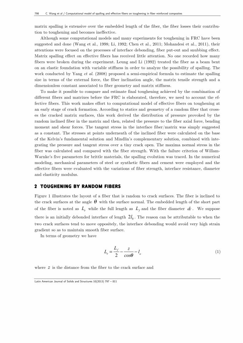
Figure 1 illustrates the layout of a fiber that is random to crack surfaces. The fiber is inclined to the crack surfaces at the angle θ with the surface normal. The embedded length of the short part of the fiber is noted as Le while the full length as Lf and the fiber diameter df . We suppose
there is an initially debonded interface of length 2l0 . The reason can be attributable to when the two crack surfaces tend to move oppositely, the interface debonding would avoid very high strain gradient so as to maintain smooth fiber surface.
In terms of geometry we have
Le =
Lf
2− z
cosθ− lo (1)
where z is the distance from the fiber to the crack surface and
C. Wang et al / Computational model of spalling and effective fibers on toughening in fiber reinforced composites 799
Latin American Journal of Solids and Structures 10(2013) 797 – 811
θ < arctan
Lf
d f
(2)
There are a number of fibers that cross the crack surfaces randomly. Each fiber contributes
itself to bridge the two opening surfaces of the crack and intends to keep them from separating. The mean effect of fiber contributions is bridging stress. Just due to this bridging stress, the toughening is achieved. The bridging stress can be determined by the following equation, modi-fied from the one proposed by Wang et al. (1988):
Figure 1 Geometry of an inclined fiber.
σ c(w) =
Vf
Af
N (w,θ , z)P(θ ) p(z)dz dθz=0
( Lf cosθ−d f sinθ )/2
∫θ=0
arctan( Lf /d f )
∫ (3)
where V f - volume fraction of fibers; Af - section area of a fiber; N w,θ , z( ) - the fiber axial
force; w - the open of crack surfaces; P(θ ) and p(z) - the distribution functions of fiber incli-ned angles and fiber center locations respectively, given by
P(θ ) = sinθ for 0 ≤θ ≤ arctan(Lf / d f ) (4)
p z( ) = 2
Lf
for 0 ≤ z ≤Lf cosθ − d f sinθ
2
(5)
After obtaining the bridging stress, the increment of fracture energy Gc [J / m2] , i.e.
800 C. Wang et al / Computational model of spalling and effective fibers on toughening in fiber reinforced composites
Latin American Journal of Solids and Structures 10(2013) 797 – 811
toughening, can be calculated as the area under the curve σ c − w , using the following integral:
Gc = σ c
0
w*
∫ w( )dw (6)
where w* should be the ultimate crack open for which all fiber axial forces become zero, that is, all the fibers are pulled apart or out the matrix.
From Eq. (3) we see that to determine the bridging stress, the key is to find the axial force of the inclined fiber N w,θ , z( ) related to the crack open w and the embedded length Le or the
distance from the fiber center to the surface z . This is major difficulty in toughening simulation, because one or more of the events such as interface debonding, matrix spalling, snubbing effect, fiber pull-out or breakage may come about.
In this work, our attention was focused neither on bridging stress nor the toughening compu-tation, but on effective fibers at an early stage of crack formation with a tiny crack open ( w =0.1 µm), for which the interface debonding should not appear, except for the part of length 2l0 .
3 TOUGHENING BY RANDOM FIBERS
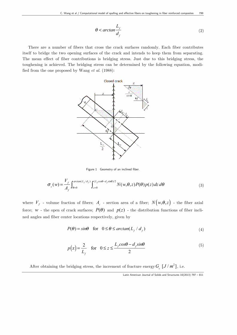
Although spalling effect is of great importance in toughening analysis, the researchers did not pay much attention on it. Few computational models that account for spalling were reported (Yang and Li, 2008). Zhang and Li (2002) and Yang and Li (2008) suggested the pressure distribution as the one based on elastic fundamental beam theory. This is improper, because the presupposi-tion of the elastic fundamental beam theory is that the elastic coefficient of the foundation is constant, which only match the case when a fiber is orthogonal to the crack plane or θ = 0 . Generally a random fiber is inclined to the crack plane with θ ≠ 0 , so the formula of elastic fun-damental beam theory does not hold. We propose a computational model for effective fibers, in which mechanical properties of fibers, matrix and interface fiber/matrix as well as spalling effect are concerned. 3.1 Analys is of stat ic equi l ibr ium and deformation of an incl ined f iber with the crack opening When the crack surfaces open, the inclined fiber will shift from the initial position and suffer de-formation (Figure 2). The fiber bridging force Fbr perpendicular to the crack surfaces is the re-sultant of the axial force N and the shear P , which lead to the displacements respectively in the directions u1 e u2 of the section center A
' of the embedded part of the fiber at the point where
the fiber exits the matrix and the deformation of the unembedded part (the debonded part 2l0 , Figure 3). It is easy to know:
C. Wang et al / Computational model of spalling and effective fibers on toughening in fiber reinforced composites 801
Latin American Journal of Solids and Structures 10(2013) 797 – 811
Fbr = Ncosθ + Psinθ = N / cosθ (7)
Figure 2 Fiber positions before and after deformation when the crack opened to 2w.
N – axial force, P – shear and M – bending moment.
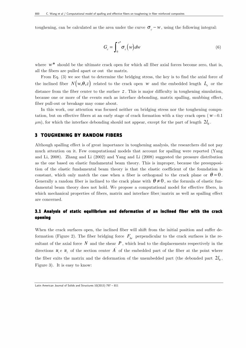
Figure 3 Static equilibrium diagram of the debonded part of the fiber. ∆ℎ is the distance in u2 direction between the points A and O
(The stretch ∆𝑙 = 𝐴𝐴! of the debonded part of the fiber is quite exaggerated). The stretched length Δl = AA' of the initially debonded part l0 has a component in the di-
rection normal to the crack surfaces i.e. in the direction u1 (Figure 3). Therefore we can write the half open of the crack as
802 C. Wang et al / Computational model of spalling and effective fibers on toughening in fiber reinforced composites
Latin American Journal of Solids and Structures 10(2013) 797 – 811
w = Δl cosθ + u1e (8)
where Δl = Nl0 / Af E f and u1
e denotes the displacement in the direction u1 of the point A'
(Figure 3) of the left part of the embedded fiber. 3.2 Pressure imposed by f iber on matr ix
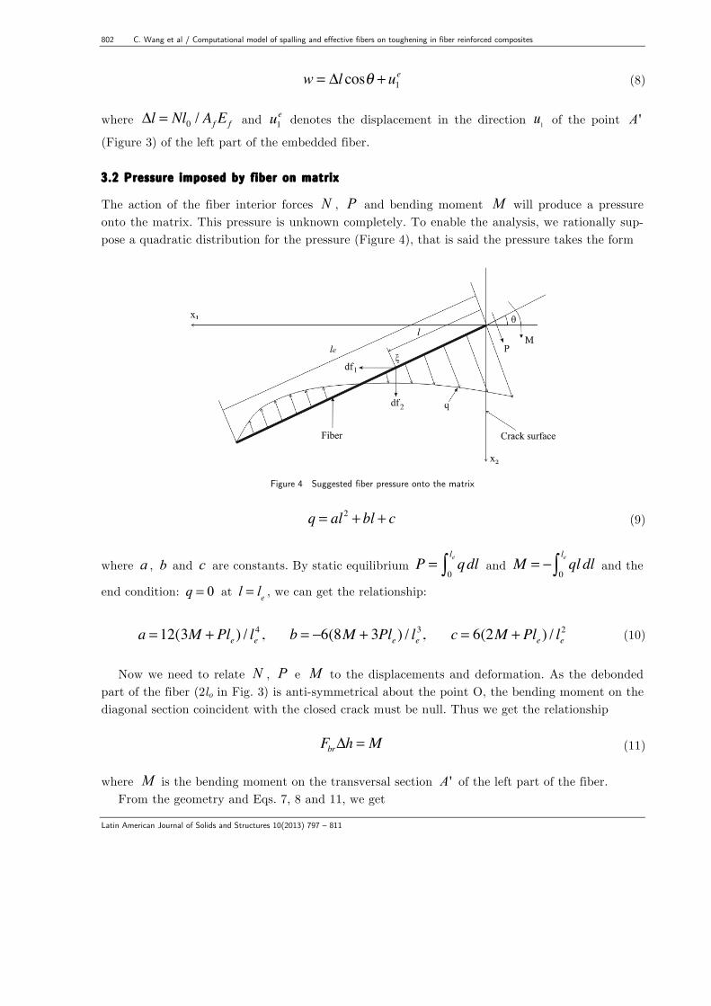
The action of the fiber interior forces N , P and bending moment M will produce a pressure onto the matrix. This pressure is unknown completely. To enable the analysis, we rationally sup-pose a quadratic distribution for the pressure (Figure 4), that is said the pressure takes the form
Figure 4 Suggested fiber pressure onto the matrix
q = al2 + bl + c (9)
where a , b and c are constants. By static equilibrium P = qdl0
le∫ and M = − ql dl0
le∫ and the
end condition: q = 0 at l = le , we can get the relationship:
a = 12(3M + Ple ) / le4 , b = −6(8M + 3Ple ) / le
3, c = 6(2M + Ple ) / le2 (10)
Now we need to relate N , P e M to the displacements and deformation. As the debonded
part of the fiber (2lo in Fig. 3) is anti-symmetrical about the point O, the bending moment on the diagonal section coincident with the closed crack must be null. Thus we get the relationship
FbrΔh = M (11)
where M is the bending moment on the transversal section A' of the left part of the fiber.
From the geometry and Eqs. 7, 8 and 11, we get
C. Wang et al / Computational model of spalling and effective fibers on toughening in fiber reinforced composites 803
Latin American Journal of Solids and Structures 10(2013) 797 – 811
Δh = Δlsinθ + u2
e + rsinθtanθ = (N .lo
E f Af
)sinθ + u2e + rtanθsinθ (12)
By Eqs. 11 and 12 we obtain
M = Fbr (
NlosinθE f Af
+ u2e + rtanθsinθ ) = Fbr[(
NE f Af
+1)rtanθsinθ + u2e] (13)
For full crack open, one can write
1 1 1 122 ( ) ( )fe d e do
f ff f
NdNlw u u cos u u sinE A E A
θ θ+ += + = + (14)
where u1
e and u2
e denote the displacements of the point A' (Figure 3) of the left embedded fiber
while u1d and u2
d for the ones of the point B ' .
In this way we relate the crack open with the axial force N . At first appearance the crack open is only linked to the axial force N , but in fact eu1 and du1 are implicit functions of N , P , and M . Therefore Eq. 14 is implicit and self-consistent. For a given w , the suitable N should satisfy Eq. 14. Since the force N is tensile, then eu1 and du1 should be negative respectively. The
role of eu1 and du1 tends to diminish the crack open. From other side the component of the stret-ched part (Ndf / Af E f )sinθ tries to open the crack surfaces. There is competition between the
two sides. It would occur that the actual crack open between the two points A' and B ' is null in spite of increasing N . Generally the sum of the displacements u1
e and u1d is small compared
to the stretch component (Ndf / Af E f )sinθ . N can be determined by trial, beginning with the
approximation
N ≈ 2wE f Af / d f sinθ (15)
After the determination of N , we can obtain M , Fbr and P , then followed by a , b and c .
As no debonding arises on the interface for the embedded fiber on the stage of small crack open, the interface shear stress is simply supposed as
qa = N / d fπ le (16)
804 C. Wang et al / Computational model of spalling and effective fibers on toughening in fiber reinforced composites
Latin American Journal of Solids and Structures 10(2013) 797 – 811
3.3 Kelvin’s fundamental solut ion of and Mindl in’s complementary solut ion
The Kelvin’s fundamental solution (Love, 1944) derived the analytic expressions of the displace-ments and stresses provoked by a unit force in an infinite continuum. To keep the validation of the Kelvin’s solution in a half space, Mindlin (1936) gave the additional solution, called as the Mindlin’s complementary solution. Hence the displacement and stress solutions attributed to the action of a unit force can be written respectively as (Brebbia et al., 1984)
uij = uij
( K ) (ξ ,x)+ uij(C ) (ξ ,x) (17)
σ kji =σ kji
( K ) (ξ ,x)+σ kji(C ) (ξ ,x)
(18)
uij
( K ) (ξ ,x) = 116π (1−ν )Gr
(3− 4ν )δ ij + r,i .r, j⎡⎣ ⎤⎦ , i, j, k = 1, 2, 3
(19)
σ jki
( K ) (ξ ,x) = − 14απ (1−ν )rα (1− 2ν )(r,kδ ij + r, jδ ki − r,iδ jk )− βr,i .r, j .r,k
⎡⎣ ⎤⎦ (20)
where 2=α and 3=β for plane deformation state; v – ratio of Poisson; G – shear elasticity modulus; r – the distant from the source point ξ to the field point x ; the Kelvin’s solution
uij
( K ) (ξ ,x) is the i direction displacement of a field point x induced by a unit force applied at a
source point ξ in the j direction; σ jki
( K ) (ξ ,x) is the stress tensor induced by a unit force applied
at a source point ξ in the i direction. The stresses can be obtained through the integration of the pressures q and qa over the interface:
uj = uji(K ) + uji
(C )( )le∫ dfi (21)
σ jk = σ jki(K ) +σ jki
(C )( )le∫ dfi
(22)
where
uij(C ) (ξ ,x) and
σ jki(C ) (ξ ,x)
are Mindlin’s complementary solutions (Mindlin, 1936) and the
elementary forces:
df1 = − qsinθ + qad fπ cosθ( )dl (23)
df2 = − qcosθ + qad fπ sinθ( )dl (24)
C. Wang et al / Computational model of spalling and effective fibers on toughening in fiber reinforced composites 805
Latin American Journal of Solids and Structures 10(2013) 797 – 811
4 SIMULATION AND RESULT ANALYSIS
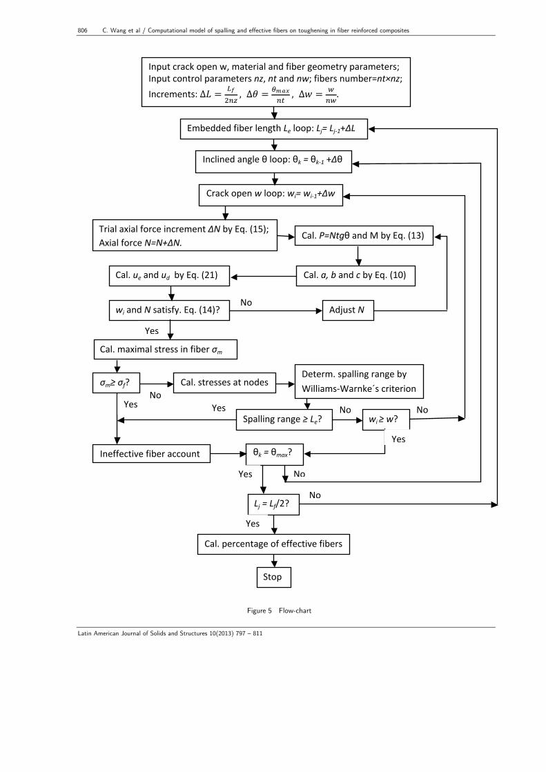
Spalling usually happens before the initiation of interface debonding. Upon interface debonding comes about, the obtained pressure and shear distributions do not valid more. For this reason we set a tiny crack open w to 0.1 µm for all simulations and divided it into 20 small increments. We also split the inclined angle θ into nt small increments and the embedded length into nz . We calculated respective stresses at these discrete points with different numerical pars: θ and z . In this way the number of fibers was considered as nt × nz . We set nt = 20 and nz = 10 in this work. That is said that 200 fibers were account for. We verified that using larger division num-bers: nt and nz have little influence on the simulated results. Figure 5 is the flow-chat of simu-lation.
The parameters employed in this work come from the experiment of cement reinforced by steel fibers realized by Leung and Shapiro (1999). Fantilli and Vallini (2007) also used them for their research work. These parameters are:
Lf = 10mm (fiber length), E f = 200GPa (fiber elasticity
modulus), v f = 0.3 (coefficient of Poisson of fiber), Em = 30GPa (matrix elasticity modulus),
vm = 0.2 (coefficient of Poisson of matrix), ft = 3.7MPa (matrix tensile strength),
fc = 36.5MPa (matrix compressive strength). 4.1 Spal l ing evolut ion
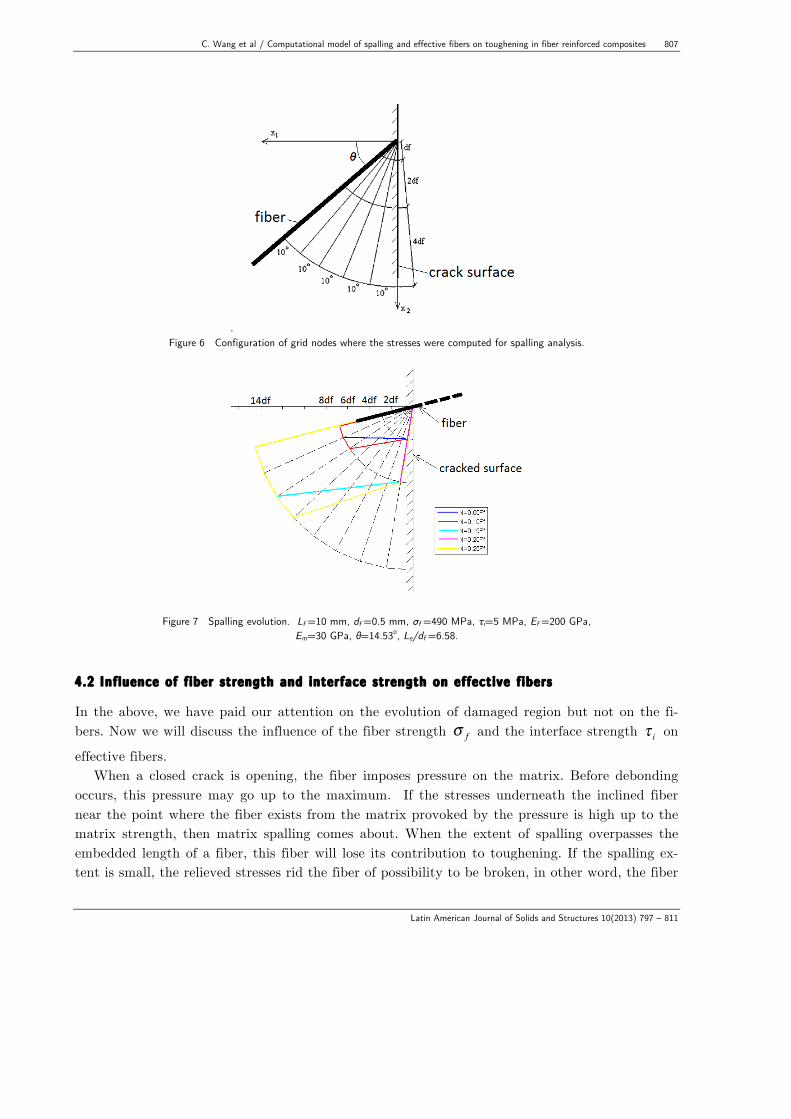
The pressure attributed by an inclined fiber and imposed onto the matrix could result matrix spalling. To identify if the matrix is damaged, we has used the criterion of Willam-Warnke’s five parameters for brittle material (Willam and Warnke, 1975). The verification of spalling was taken at some points in the compressive zone that is supporting the fiber. We set them as nodes of a polar coordinate grid (Fig. 6). The arc radii of the grid expand forth with the values: df, 3df, 7df and 15df. The support angle 90−θ( ) was divided into small ones of 10o approximately. To trace
the evolution of spalling (damage), we applied the axial load N at several small steps till the fiber was broken i.e. the fiber tensile strength was reached, then, recorded the regions damaged respectively.
Fig. 7 illustrates a typical spalling evolution. The value in the legend indicates how much was the axial force meanwhile the fiber was broken. The damage always is initiated at the point where the fiber exits the matrix. For the fiber with a small inclined angle like the one indicated in Fig. 7, the spalling region is small at beginning but expands rapidly. The fiber was not broken until high bridging force was reached (about 40% of fiber strength in force Ff =σ f Af ). However for
the fiber with a large inclined angle, the initial damage extent already is very large. Only with a quite low bridging force (only about 5% of the fiber strength in force Ff ), the fiber has been
broken. From Eq. (13) it could be seen that a high inclined angle results in large bending mo-ment. As a consequence, the bending stress is high, although the bridging force is still low.
806 C. Wang et al / Computational model of spalling and effective fibers on toughening in fiber reinforced composites
Latin American Journal of Solids and Structures 10(2013) 797 – 811
!!!!!!!!!!!!!!!!!!!!!!!!!!!!!!!!!!!!!!!!!!!!! Figure 5 Flow-chart
Nos!!
Nos!!
Input!crack!open!w,!material!and!fiber!geometry!parameters;!Input!control!parameters!nz,!nt!and!nw;!fibers!number=nt×nz;!Increments:!∆! = !!
!!" , ∆! =!!"#!" , ∆! = !
!".!
Embedded!fiber!length!Le!loop:!Lj=!Lj+1+∆L!
Inclined!angle!θ!loop:!θk!=!θk+1!+∆θ!
Crack!open!w!loop:!wi=!wi+1+∆w!
Trial!axial!force!increment!∆N!by!Eq.!(15);!Axial!force!N=N+∆N.!
Cal.!P=Ntgθ!and!M!by!Eq.!(13)!
Cal.!a,!b!and!c!by!Eq.!(10)!Cal.!ue!and!ud!!by!Eq.!(21)!
wi!and!N!satisfy.!Eq.!(14)?!
Cal.!percentage!of!effective!fibers!
Cal.!maximal!stress!in!fiber!σm!
σm≥!σf?! Cal.!stresses!at!nodes!Determ.!spalling!range!by!!WilliamsSWarnke´s!criterion!
Spalling!range!≥!Le?! wi!≥!w?!
Ineffective!fiber!account! θk!=!θmax?!
Lj!=!Lf/2?!
Adjust!N!!
Yes!!Nos!!
Nos!!
Yes!!
Yes!!
Yes!!
Nos!!
Yes!!
Nos!!
Yes!!
Stop!!
C. Wang et al / Computational model of spalling and effective fibers on toughening in fiber reinforced composites 807
Latin American Journal of Solids and Structures 10(2013) 797 – 811
. Figure 6 Configuration of grid nodes where the stresses were computed for spalling analysis.
Figure 7 Spalling evolution. Lf =10 mm, df =0.5 mm, σf =490 MPa, τi=5 MPa, Ef =200 GPa, Em=30 GPa, θ=14.53o, Le/df =6.58.
4.2 Inf luence of f iber strength and interface strength on effect ive f ibers
In the above, we have paid our attention on the evolution of damaged region but not on the fi-bers. Now we will discuss the influence of the fiber strength σ f and the interface strength τ i on
effective fibers. When a closed crack is opening, the fiber imposes pressure on the matrix. Before debonding
occurs, this pressure may go up to the maximum. If the stresses underneath the inclined fiber near the point where the fiber exists from the matrix provoked by the pressure is high up to the matrix strength, then matrix spalling comes about. When the extent of spalling overpasses the embedded length of a fiber, this fiber will lose its contribution to toughening. If the spalling ex-tent is small, the relieved stresses rid the fiber of possibility to be broken, in other word, the fiber
808 C. Wang et al / Computational model of spalling and effective fibers on toughening in fiber reinforced composites
Latin American Journal of Solids and Structures 10(2013) 797 – 811
is saved and can make contribution to toughening. The interface debonding also can save the fiber. We rated the fortune of a fiber into four categories:
(i) broken – the tensile stress
σ m = 4N / πd f
2 + 32M / πd f3 (25)
in the fiber hit the fiber tensile strengthσ f . In spite of existence of shear stress in the fiber, we
ignored its influence, since the shear stress was low at earlier stage of the crack open. (ii) spalling – the extent of spalling overpassed the embedded length of the fiber; (iii) debonded – the maximal shear stress on the surface of the embedded fiber was equal to or
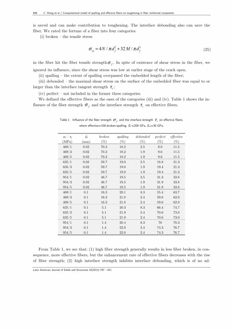
larger than the interface tangent strength τ i ; (iv) perfect – not included in the former three categories. We defined the effective fibers as the ones of the categories (iii) and (iv). Table 1 shows the in-
fluence of the fiber strength σ f and the interface strength τ i on effective fibers.
Table 1 Influence of the fiber strength fσ and the interface strength iτ on effective fibers,
where effective=100-broken-spalling. Ef =200 GPa, Em=30 GPa.
σf / τi df broken spalling debonded perfect effective (MPa) (mm) (%) (%) (%) (%) (%) 469/1 0.02 70.3 18.2 2.5 9.0 11.5 469/3 0.02 70.3 18.2 1.9 9.6 11.5 469/5 0.02 70.3 18.2 1.9 9.6 11.5 635/1 0.02 59.7 19.0 2.5 18.8 21.3 635/3 0.02 59.7 19.0 1.9 19.4 21.3 635/5 0.02 59.7 19.0 1.9 19.4 21.3 954/1 0.02 46.7 19.5 2.5 31.3 33.8 954/3 0.02 46.7 19.5 1.9 31.9 33.8 954/5 0.02 46.7 19.5 1.9 31.9 33.8 469/1 0.1 16.3 20.1 8.3 55.4 63.7 469/3 0.1 16.3 21.8 2.4 59.6 62.0 469/5 0.1 16.3 21.8 2.4 59.6 62.0 635/1 0.1 5.1 20.3 8.3 66.4 74.7 635/3 0.1 5.1 21.9 2.4 70.6 73.0 635/5 0.1 5.1 21.9 2.4 70.6 73.0 954/1 0.1 1.4 20.4 8.3 70 78.3 954/3 0.1 1.4 22.0 2.4 74.3 76.7 954/5 0.1 1.4 22.0 2.4 74.3 76.7
From Table 1, we see that: (1) high fiber strength generally results in less fiber broken, in con-
sequence, more effective fibers, but the enhancement rate of effective fibers decreases with the rise of fiber strength; (2) high interface strength inhibits interface debonding, which is of no ad-
C. Wang et al / Computational model of spalling and effective fibers on toughening in fiber reinforced composites 809
Latin American Journal of Solids and Structures 10(2013) 797 – 811
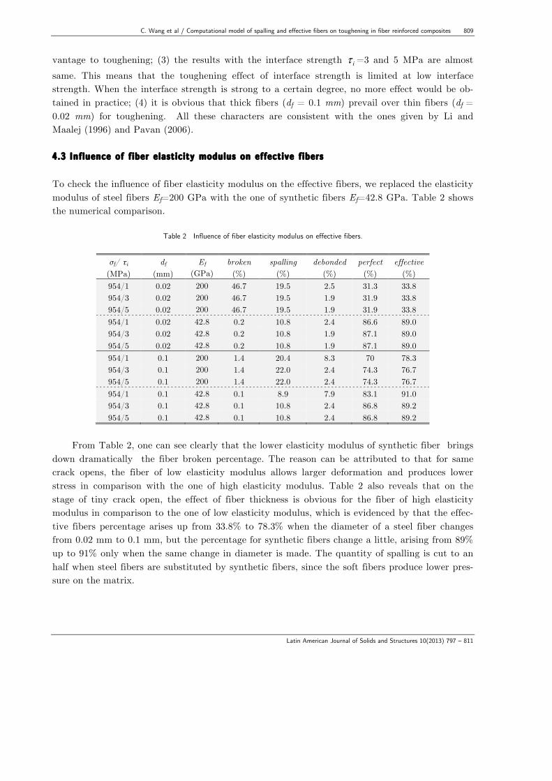
vantage to toughening; (3) the results with the interface strength iτ =3 and 5 MPa are almost same. This means that the toughening effect of interface strength is limited at low interface strength. When the interface strength is strong to a certain degree, no more effect would be ob-tained in practice; (4) it is obvious that thick fibers (df = 0.1 mm) prevail over thin fibers (df = 0.02 mm) for toughening. All these characters are consistent with the ones given by Li and Maalej (1996) and Pavan (2006). 4.3 Inf luence of f iber e last ic ity modulus on effect ive f ibers To check the influence of fiber elasticity modulus on the effective fibers, we replaced the elasticity modulus of steel fibers Ef=200 GPa with the one of synthetic fibers Ef=42.8 GPa. Table 2 shows the numerical comparison.
Table 2 Influence of fiber elasticity modulus on effective fibers.
σf/ τi df Ef broken spalling debonded perfect effective (MPa) (mm) (GPa) (%) (%) (%) (%) (%) 954/1 0.02 200 46.7 19.5 2.5 31.3 33.8 954/3 0.02 200 46.7 19.5 1.9 31.9 33.8 954/5 0.02 200 46.7 19.5 1.9 31.9 33.8 954/1 0.02 42.8 0.2 10.8 2.4 86.6 89.0 954/3 0.02 42.8 0.2 10.8 1.9 87.1 89.0 954/5 0.02 42.8 0.2 10.8 1.9 87.1 89.0 954/1 0.1 200 1.4 20.4 8.3 70 78.3 954/3 0.1 200 1.4 22.0 2.4 74.3 76.7 954/5 0.1 200 1.4 22.0 2.4 74.3 76.7 954/1 0.1 42.8 0.1 8.9 7.9 83.1 91.0 954/3 0.1 42.8 0.1 10.8 2.4 86.8 89.2 954/5 0.1 42.8 0.1 10.8 2.4 86.8 89.2
From Table 2, one can see clearly that the lower elasticity modulus of synthetic fiber brings
down dramatically the fiber broken percentage. The reason can be attributed to that for same crack opens, the fiber of low elasticity modulus allows larger deformation and produces lower stress in comparison with the one of high elasticity modulus. Table 2 also reveals that on the stage of tiny crack open, the effect of fiber thickness is obvious for the fiber of high elasticity modulus in comparison to the one of low elasticity modulus, which is evidenced by that the effec-tive fibers percentage arises up from 33.8% to 78.3% when the diameter of a steel fiber changes from 0.02 mm to 0.1 mm, but the percentage for synthetic fibers change a little, arising from 89% up to 91% only when the same change in diameter is made. The quantity of spalling is cut to an half when steel fibers are substituted by synthetic fibers, since the soft fibers produce lower pres-sure on the matrix.
810 C. Wang et al / Computational model of spalling and effective fibers on toughening in fiber reinforced composites
Latin American Journal of Solids and Structures 10(2013) 797 – 811
5 CONCLUSIONS
Modeling of fiber toughening in brittle matrix is complicated, involving all of geometric and me-chanical parameters of fiber, matrix as well as interface. Instead of toughening in quantity, the focus of this work was on computational model for the analysis of effective fibers at an early stage of crack formation with the consideration of spalling matrix. The results based on the presented computational model show that high fiber strength can enhance the effective fibers at earlier stage of crack open. High interface strength inhibits interface debonding. Low elasticity modulus combined high strength of fibers can raise dramatically effective fibers in comparison with high elasticity modulus combined high strength, which will benefit toughening in matrix. Soft fibers produce lower pressure on the matrix and result in less spalling than hard fibers. The effect of fiber thickness is more sensitive for fibers of high elasticity modulus than fibers of lower elasticity modulus. We have not made quantitative comparison with experiments in this work, since no experimental data of effective fibers is available from literature, but the presented fiber pressure model is applicable for toughening analysis either at earlier stage of interface debonding or in fiber pull-out process.
Acknowledgements The authors acknowledge the National Council for Scientific and Technolo-gical Development (CNPq, a Brazilian government agency of financial aid: Grant No. 501660/2009-7) for its finance support in this work.
References [1] Brebbia, C.A., Telles, J.C.F., Wrobel, L.C., (1984). Boundary Element Techniques. Theory and Applications
in Engineering, Springer-Verlag (New York). [2] Chen, X., Beyerlein, I.J., Brinson, L.C., (2011). Bridged crack models for the toughness of composites rein-
forced with curved nanotubes, J. Mech. Phys. Solids 59: 1938-1952. [3] Fantilli, P.A. and Vallini, P., (2007). A cohesive interface model for the pullout of inclined steel fibers in
cementitious matrixes, Journal of Advanced Concrete Technology 5: 247-258. [4] Katz, A. and Li, V.C., (1995). Inclination angle effect of carbon fibers in cementitious composites, ASCE J.
of Eng. Mech. 121: 1340-1348. [5] Leung, C.K.Y. and Li, V.C., (1992). Effect of fiber inclination on crack bridging stress in brittle fiber
reinforced brittle matrix composites, J. Mech. Phys. Solids 40:1333-1362. [6] Leung C.K.Y. and Shapiro, N., (1999). Optimal steel fiber strength for reinforcement of cementitious materi-
als, J. Materials in Civil Engineering 11: 116-123. [7] Li, V.C., Wang, Y., Backer, S., (1991). A micromechanical model of tension softening and bridging toughen-
ing of short random fiber reinforced brittle matrix composites, J. Mech Phys. Solids 39: 607- 625. [8] Li, V.C., (1992). A simplified micromechanical model of compressive strength of fiber-reinforced cementitious
composites, Cement & Concrete Composites 14: 131-141. [9] Love, A.E.H. (1944). Treatise on the Mathematical Theory of Elasticity, Dover (New York). [10] Li, V.C. and Maalej, M., (1996). Toughening in cement based composites. Part II: Fiber reinforced cementi-
tious composites, Cement & Concrete Composites 18: 239-249. [11] Mindlin, R.D., (1936). Force at a point in the interior of semi-infinite solid, Physics 7: 195-202.
C. Wang et al / Computational model of spalling and effective fibers on toughening in fiber reinforced composites 811
Latin American Journal of Solids and Structures 10(2013) 797 – 811
[12] Mohandesi, J.A., Sangghaleh, A., Nazari, A., Pourjavad, N., (2011). Analytical modeling of strength in ran-domly oriented PP and PPTA short fiber reinforced gypsum composites, Computational Materials Science 50: 1619-1624.
[13] Pavan, A.R. (2006). Mathematical modeling of toughening in ceramic materials by addition of micro fibers, Master paper (in Portuguese), Northwest Regional University of Rio Grande do Sul, Brazil.
[14] Wang, Y., Li, V.C., Backer, S., (1988). Modelling of fibre pull-out from a cement matrix, Int. J. Cement Composites Lightweight Concrete 10: 143-149.
[15] William K.J. and Warnke, E.P., (1975). Constitutive model for the triaxial behavior of concrete, in: Pro-ceedings of International Association for Bridge and Structure Engineering, Report 19, Section III. Zurich, 1- 30.
[16] Yang, E.H. and Li, V.C., (2008). Fiber-bridging Constitutive Law of Engineered Cementitious Composites, J. Advanced Concrete Technology 6: 181-193.
[17] Zhang, J. and Li, V.C., (2002). Effect of inclination angle on fiber rupture load in fiber reinforced cementitious composites. Composites Science and Technology 62: 775-781.