Embed Size (px)
Citation preview
1117 lbEF TRANSACTIONS O N MICROWAVE THFORY 4PUD TtCHNIQUES V O L 40 N O 6 J U N F 1492
Computer-Aided Design of Beam Forming Networks for Modern Satellite Antennas
Ferdinand0 Alessandri, Member, IEEE, Mauro Mongiardo, Roberto Sorrentino, Fellorc , IEEE
Abstract-Multicontoured and reconfigurable beam space- craft antennas rely on sophisticated beam forming networks (BFN). Accurate and efficient CAD tools a re required to meet the stringent requirements on the power division, while avoid- ing any tuning or trimming of the BFN. This paper presents advanced field theoretical techniques for the analysis and op- timization of microwave beam forming networks realized in both waveguide and square coaxial cable technologies. Such advances consist in new segmentation techniques of the micro- wave components associated with efficient mode-matching for- mulations for the modeling of isolated as well as coupled dis- continuities. The achieved numerical efficiency allows sophisticated synthesis procedures, based on repeated full-wave analysis in wide frequency bands, to be performed on small machines such as a 386 PC. The design tools developed have been widely validated through a comprehensive test campaign.
I . INTRODUCTION
HE USE in communication satellites of contoured and T reconfigurable beam antennas has required the devel- opment of rather complex Beam Forming Networks (BFN) to generate the necessary amplitude and phase distribution on the feed elements. In many cases most of the com- plexity, cost and weight of the antennas is accounted to the BFN that requires skilled expertise to develop high quality and low cost products. The ultimate antenna per- formances in fact is strictly related to the illumination ac- curacy of the reflector in the operational frequency band and temperature range.
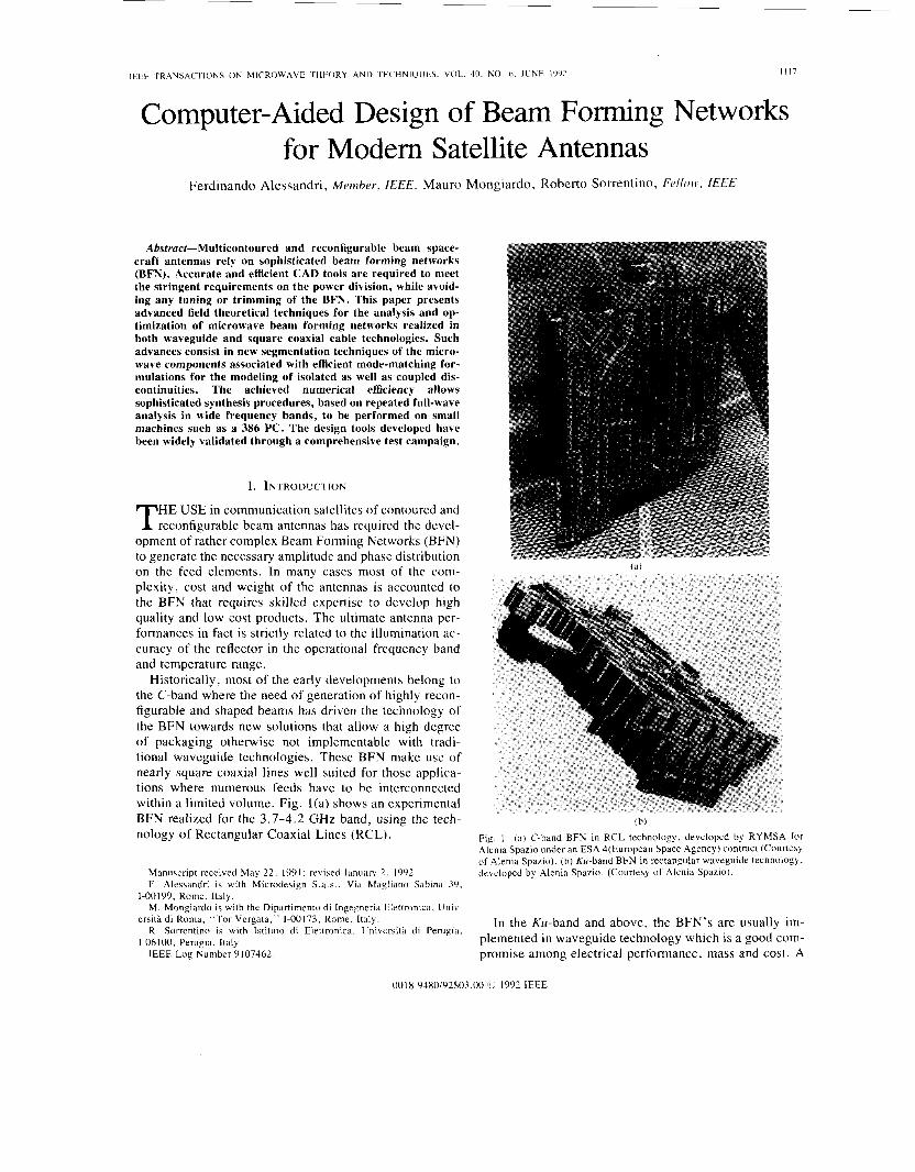
Historically, most of the early developments belong to the C-band where the need of generation of highly recon- figurable and shaped beams has driven the technology of the BFN towards new solutions that allow a high degree of packaging otherwise not implementable with tradi- tional waveguide technologies. These BFN make use of nearly square coaxial lines well suited for those applica- tions where numerous feeds have to be interconnected within a limited volume. Fig. l(a) shows an experimental BFN realized for the 3.7-4.2 GHz band, using the tech- nology of Rectangular Coaxial Lines (RCL).
Manuscript received May 22, 1991; revised January 2. 1992. F . Alessandri is with Microdesign S.a .s . . Via Magliano Sabina 39,
M. Mongiardo is with the Dipartimento di Ingegneria Elettronica, U n i v -
R . Sorrentino is with lstituto di Elettronica. Univcrsita di Perugia,
IEEE Log Number 9107462.
1-00199, Rome, Italy.
ersita di Roma, “Tor Vergata,” 1-00173. Rome, Italy.
1-06100, Perugia, Italy.
(b)
Fig. 1 . ( a ) C-band BFN in RCL technology. developed by RYMSA for Alenia Spazio under an ESA 4(European Space Agency) contract (Courtesj of Alenia Spazio). (b) Ku-band BFN in rectangular waveguide technology, developed by Alenia Spazio. (Courtesy of Alenia Spazio).
In the Ku-band and above, the BFN’s are usually im- plemented in waveguide technology which is a good com- promise among electrical performance, mass and cost. A
0018-9480/92$03.00 rC, 1992 IEEE
1118 IEEE TRANSACTIONS ON MICROWAVE THEORY AND TECHNIQUES. VOL. 40. NO. 6. JUNE 1992
waveguide BFN for the 10.95-12.75 GHz band is shown in Fig. l(b).
The BFN represents the heart of the antenna system. It has to generate the complex excitations necessary to shape the radiation pattern. It consists of a number of power dividers and fixed phase shifters to adjust the phase of the signal at each feeding element. Key requirements for the BFN are wide band operation (up to 35 %), high precision power division (typically 0.5 dB in amplitude and 5" in phase), high power capability (about 300 W CW) and re- liable technology for space environment.
To this end, accurate and efficient CAD techniques are of paramount importance. To attain the degree of accu- racy required, the design must be based on rigorous field- theory techniques. Parasitic reactances and reactive cou- plings between discontinuities affect significantly the electrical performances of the components. Numerical ef- ficiency of the algorithms is also very important as nu- merical optimization based on a large number of repeated computer analyses is to be applied. The ultimate objective is the availability of CAD tools which allow one to design the entire BFN avoiding any trimming and tuning, with obvious advantage in terms of cost and development schedule.
The aim of this paper is to provide a state-of-the-art description of the electromagnetic tools developed for the computer-aided analysis and optimization of microwave components for modem BFN. These tools have been de- veloped for personal computers and have been widely val- idated through a comprehensive test campaign.
Computational techniques discussed here are based on the mode-matching (MM) method [l]. Though MM is a quite efficient numerical method, the computer effort for the analysis and mainly the optimization of complicated structures is still too high. Optimization procedures re- quire in fact hundreds or thousands repeated analyses at all frequency points of interest. Various techniques have been devised in order to reduce the computational effort still providing an extremely high accuracy.
The CAD of a complicated microwave component con- sists basically of the following steps:
i) segmentation of the structure into elementary cells or discontinuities;
ii) modeling of elementary cells or discontinuities in terms of a generalized multiport description;
iii) analysis of the overall equivalent network that re- sults from the electrical connection of the individual mul- tiport circuits.
The efficiency of the CAD technique can be improved by reducing the complexity of the overall equivalent net- work by proper segmentation techniques, and/or by re- ducing the complexity of the individual multiports by suitable modifications of the MM description. These as- pects are specifically addressed in this paper.
The generalized multiport description of elementary waveguide discontinuities based on conventional MM technique is presented first (Section 11). The improve- ments that are obtained by modified MM technique are
~
then discussed in Section 111, while Section IV is devoted to the segmentation techniques for complicated structures and devices. RCL's can be viewed as special cases of waveguide structures, and the analysis of both uniform and discontinuous RCL's is illustrated in Section V.
Design examples of waveguide components such as multiport branch guide couplers and phase shifters, and of RCL configurations are presented in the last Section, showing excellent accuracy of the simulated responses obtained with a relatively low computer effort.
11. WAVEGUIDE DISCONTINUITIES The CAD technique adopted in this paper is based on
the application of the Mode-Matching (MM) method or modal analysis [ l ) . Modifications of the method are im- plemented in a number of cases in order to improve its efficiency, i.e., improve the numerical accuracy while re- ducing the computer effort. It should be mentioned that, while the modal analysis of single discontinuities is a standard and relatively simple technique, its application to complicated components is not so obvious. Different formulations can be used both for modeling isolated dis- continuities and for analyzing microwave structures through segmentation techniques. Considerable improve- ments in the numerical efficiency can be obtained apply- ing the appropriate technique.
The basic approach to waveguide discontinuity prob- lems consists of expanding the electromagnetic (EM) field existing in a waveguide "A" into a set of normal modes. Using expansions in TE-to-z (or TE'") and TM-to-z (or TM"' ) modes, the following expressions for the field components transverse to z can be used [2]:
E A t = vAn ( z ) eAn (x, y )
H A t = I A n ( z ) h,4n (x , y ) (1)
where the transverse eigenvectors are related by
hAn = b (2)
for both TE'" and TM"' modes. For practical reasons, the above series have to be truncated to a finite number of terms, say N A . The higher NA the more accurate the field representation and the higher the numerical effort. Trun- cating the series is a critical point in the application of MM technique. This will not be discussed here. The in- terested reader is referred to [3], [4].
The eigenvectors for the electric and magnetic fields satisfy the orthonormalization condition
= 1, e A n X h A m * 20 ds = 6mn (3)
S being the waveguide cross section, am, is the Kronecker delta. The first term in (1) corresponds to the dominant TElo mode of the rectangular waveguide.
I
ALESSANDRI et a l . : COMPUTER-AIDED DESIGN OF BEAM FORMING NETWORKS
~
1119
The EM field at any cross section z is determined by the expansion coefficients VAn(z) and ZAn(z) (n = 1, 2 , - ). These have the general form
v,, (z) = e -'@nz + e +'anz
zAn (z) = yAn [vi,, e -'onz - V i n e +"nZ 1 (4) where YAn is the wave admittance of the mode and 0, its propagation constant,
p, = (5)
k, is the free space wavenumber and k:,, the mode eigen- value.
In the analysis of discontinuity problems, different for- mulations are obtained depending on how the expansion coefficients are expressed. Assuming the wave amplitudes v+ , V - (apart from normalization coefficients) as un- knowns, a scattering matrix type formulation is obtained. This leads to the Generalized Scattering Matrix (GSM) [5] technique, but other formulations are possible. A gen- eralized impedance or admittance matrix model is ob- tained using V and I as unknowns.
The MM analysis of typical waveguide discontinuities and junctions occurring in the realization of BFN's is de- scribed in the next subsection. Both isolated and interact- ing discontinuities are considered, and the relevant appro- priate models are discussed.
A. Step Discontinuity The junction between waveguides with different cross
section is the simplest discontinuity that can be analyzed by MM technique. We consider here the case when one cross section is entirely contained in the other (boundary- reduction or boundary-enlargement type).
Three types of steps can occur in rectangular wave- guide technology, namely the E-plane, the H-plane and the double plane step. For the sake of brevity, the same formal treatment is given here for all cases. Considerable simplification is obtained in practice, when a change in one plane only occurs, since a reduced set of modes is sufficient for the field expansion. For example, for the E- plane step the EM field can be represented by the LSE'"' [6, ch. 61 mode spectrum only.
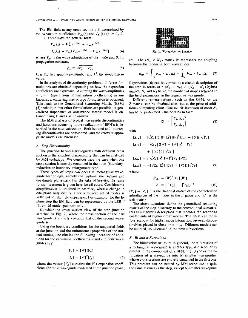
Consider the cross section view of the step junction sketched in Fig. 2, where the cross section of the first waveguide A entirely contains that of the second wave- guide B.
Using the boundary conditions for the tangential fields at the junction and the orthonormal properties of the nor- mal modes, one obtains the following linear set of equa- tions for the expansion coefficients V and I in both wave- guides [7]:
r V A l = [ W l [ V E l
= [ W ] T I I A l (6)
where the vector [VB] contains the Irs expansion coeffi- cients for the B waveguide evaluated at the junction plane,
Fig. 2. Waveguide step junction.
etc.. The (NA x Ns) matrix W represents the coupling between the modes in both waveguides:
Expressions (6) can be viewed as a circuit description of the step in terms of a (NA + NE) X (NA + NE) hybrid matrix, N A and NE being the number of modes retained in the field expansions in the respective waveguide.
Different representations, such as the GSM, or the Z-matrix, can be obtained also, but at the price of addi- tional computing effort. One matrix inversion of order NE has to be performed. One obtains in fact:
with
where
[YA] = [ZA]-' is the diagonal matrix of the characteristic admittances of the modes in the A guide and [U] is the unit matrix.
The above equations define the generalized scattering matrix of the step. Contrary to the conventional S-matrix, this is a rigorous description that includes the scattering coefficients of higher order modes. The GSM can there- fore account for higher mode interaction between discon- tinuities placed in close proximity. Different models can be adopted, as discussed in the next subsections.
B. Bi-and n-Furcations The bifurcation or, more in general, the n-furcation of
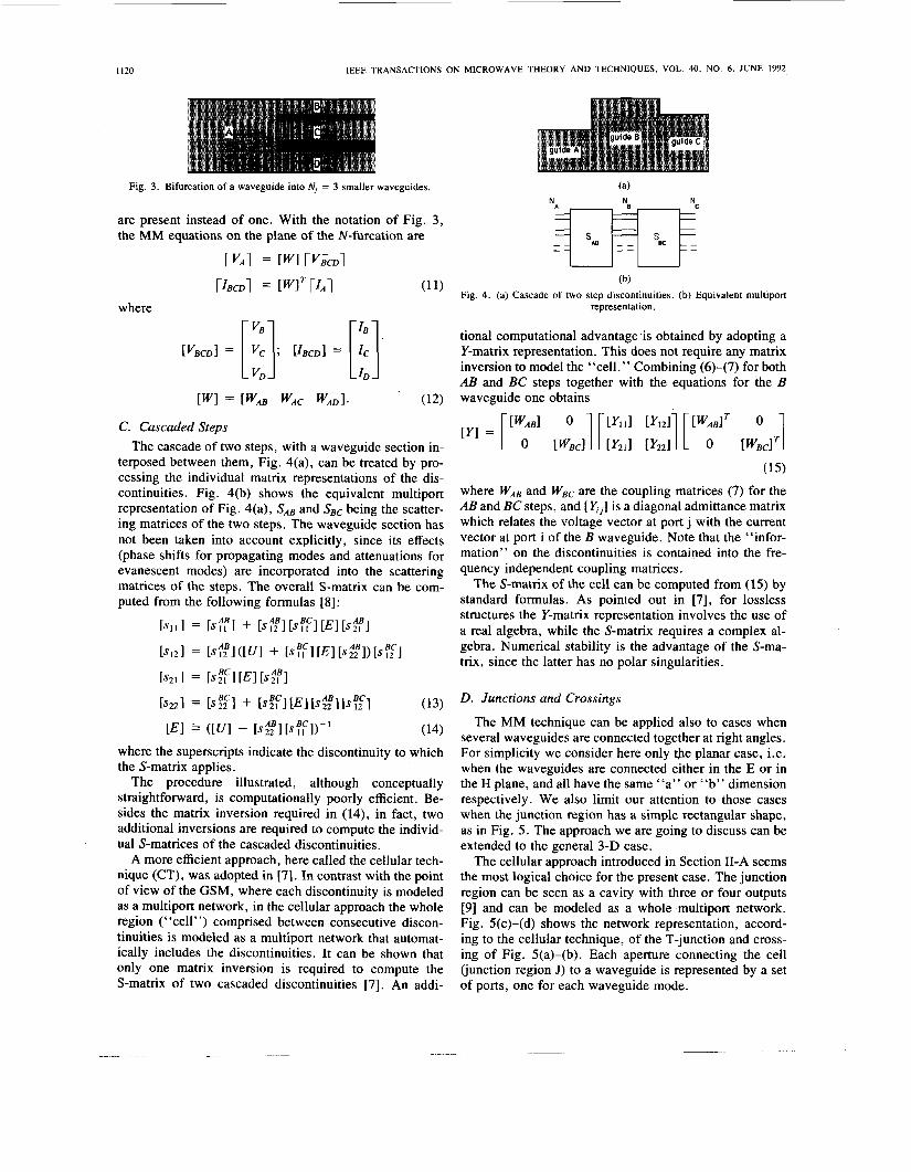
a rectangular waveguide is another typical discontinuity present in the component of a BFN. Fig. 3 shows the bi- furcation of a waveguide into N' smaller waveguides, whose cross sections are entirely contained in the first one. This problem can be treated by MM technique in quite the same manner as the step, except Nf smaller waveguide
1120 IEEE TRANSACTIONS ON MICROWAVE THEORY AND TECHNIQUES. VOL. 40, NO. 6. JUNE 1992,
Fig. 3 . Bifurcation of a waveguide into N, = 3 smaller waveguides.
are present instead of one. With the notation of Fig. 3, the MM equations on the plane of the N-furcation are
rvAi = [WI rvicDi
where
(b) (’ Fig. 4. (a) Cascade of two step discontinuities. (b) Equivalent multiport representation.
tional computational advantage .is obtained by adopting a Y-matrix representation. This does not require any matrix inversion to model the “cell.” Combining (6)-(7) for both AB and BC steps together with the equations for the B
[W1 = LWAE WAC (12) waveguide one obtains
C. Cascaded Steps The cascade of two steps, with a waveguide section in-
terposed between them, Fig. 4(a), can be treated by pro- cessing the individual matrix representations of the dis- continuities. Fig. 4(b) shows the equivalent multiport representation of Fig. 4(a), SA, and SEC being the scatter- ing matrices of the two steps. The waveguide section has not been taken into account explicitly, since its effects (phase shifts for propagating modes and attenuations for evanescent modes) are incorporated into the scattering matrices of the steps. The overall S-matrix can be com- puted from the following formulas [8]:
b 1 1 1 = [ s f l + ~ s ; ‘ 2 B l [ ~ ? ~ l [ ~ I [ ~ f l [SI21 = [42BI ([U1 + [S?,“l [El [s;4,B1) [s?3
i s 2 1 1 = [ S F I [El [s%
(15)
where WAB and WBc are the coupling matrices (7) for the AB and BC steps, and [x,] is a diagonal admittance matrix which relates the voltage vector at port j with the current vector at port i of the B waveguide. Note that the “infor- mation” on the discontinuities is contained into the fre- quency independent coupling matrices.
The S-matrix of the cell can be computed from (1 5 ) by standard formulas. As pointed out in [7], for lossless structures the Y-matrix representation involves the use of a real algebra, while the S-matrix requires a complex al- gebra. Numerical stability is the advantage of the S-ma- trix, since the latter has no polar singularities.
[El = ([VI - [~~3[s?IcI)-’ (14) where the superscripts indicate the discontinuity to which the S-matrix applies.
The procedure illustrated, although conceptually straightforward, is computationally poorly efficient. Be- sides the matrix inversion required in (14), in fact, two additional inversions are required to compute the individ- ual S-matrices of the cascaded discontinuities.
A more efficient approach, here called the cellular tech- nique (CT), was adopted in [7]. In contrast with the point of view of the GSM, where each discontinuity is modeled as a multiport network, in the cellular approach the whole region (‘ ‘cell”) comprised between consecutive discon- tinuities is modeled as a multiport network that automat- ically includes the discontinuities. It can be shown that only one matrix inversion is required to compute the S-matrix of two cascaded discontinuities [7]. An addi-
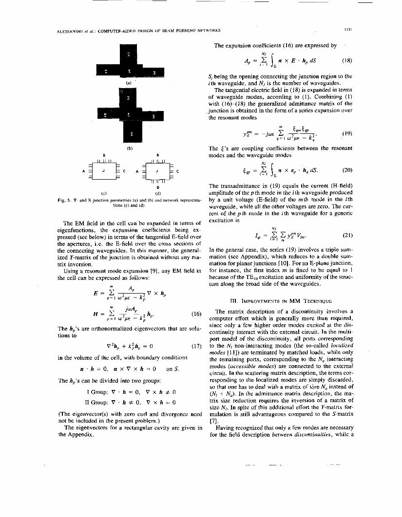
The MM technique can be applied also to cases when several waveguides are connected together at right angles. For simplicity we consider here only the planar case, i.e. when the waveguides are connected either in the E or in the H plane, and all have the same “a” or “b” dimension respectively. We also limit our attention to those cases when the junction region has a simple rectangular shape, as in Fig. 5 . The approach we are going to discuss can be extended to the general 3-D case.
The cellular approach introduced in Section 11-A seems the most logical choice for the present case. The junction region can be seen as a cavity with three or four outputs [9] and can be modeled as a whole multiport network. Fig. 5(c)-(d) shows the network representation, accord- ing to the cellular technique, of the T-junction and cross- ing of Fig. 5(a)-(b). Each aperture connecting the cell (junction region J) to a waveguide is represented by a set of ports, one for each waveguide mode.
I
ALESSANDRI et ai . : COMPUTER-AIDED DESIGN OF BEAM FORMING NETWORKS 1121
(b)
A]!>C Al$>C
D
(C) (d) Fig. 5 . T- and X-junction geometries (a) and (b) and network representa-
tions (c) and (d).
The EM field in the cell can be expanded in terms of eigenfunctions, the expansion coefficients being ex- pressed (see below) in terms of the tangential E-field over the apertures, i.e. the E-field over the cross sections of the connecting waveguides. In this manner, the general- ized Y-matrix of the junction is obtained without any ma- trix inversion.
Using a resonant mode expansion [9], any EM field in the cell can be expressed as follows:
V x hp OD *P E = C p = l w p~ - k ;
a, jwA, H = c 2 hp. p = ~ w 2 p c - k ,
The h,'s are orthonormalized eigenvectors that are solu- tions to
V2h, + k;h, = 0 (17)
in the volume of the cell, with boundary conditions
n . h = O . n x V x h = O onS.
The hp's can be divided into two groups:
I Group: V * h = 0 , V x h # 0
I1 Group: V - h # 0, V x h = 0
(The eigenvector(s) with zero curl and divergence need not be included in the present problem.)
The eigenvectors for a rectangular cavity are given in the Appendix.
The expansion coefficients (16) are expressed by
A, = .z n x E ' hp dS (18) I = NJ I s ,
Si being the opening connecting the junction region to the ith waveguide, and NJ is the number of waveguides.
The tangential electric field in (1 8) is expanded in terms of waveguide modes, according to (1). Combining (1) with (16)-( 18) the generalized admittance matrix of the junction is obtained in the form of a series expansion over the resonant modes
w r r
The 4's are coupling coefficients between the resonant modes and the waveguide modes
NJ
4, = igl n x ep - hqdS. (20) S,
The transadmittance in (19) equals the current (H-field) amplitude of the p th mode in the i th waveguide produced by a unit voltage (E-field) of the mth mode in the lth waveguide, while all the other voltages are zero. The cur- rent of the p th mode in the ith waveguide for a generic excitation is
NJ
In the general case, the series (19) involves a triple sum- mation (see Appendix), which reduces to a double sum- mation for planar junctions [ 101. For an E-plane junction, for instance, the first index m is fixed to be equal to 1 because of the TElo excitation and uniformity of the struc- ture along the broad side of the waveguides.
111. IMPROVEMENTS IN MM TECHNIQUE
The matrix description of a discontinuity involves a computer effort which is generally more than required, since only a few higher order modes excited at the dis- continuity interact with the external circuit. In the multi- port model of the discontinuity, all ports corresponding to the N I non-interacting modes (the so-called localized modes [ 1 11) are terminated by matched loads, while only the remaining ports, corresponding to the N , interacting modes (accessible modes) are connected to the external circuit. In the scattering matrix description, the terms cor- responding to the localized modes are simply discarded, so that one has to deal with a matrix of size Na instead of (NI + N,) . In the admittance matrix description, the ma- trix size reduction requires the inversion of a matrix of size N I . In spite of this additional effort the Y-matrix for- mulation is still advantageous compared to the S-matrix
Having recognized that only a few modes are necessary for the field description between discontinuities, while a
171.
1122 IEEE TRANSACTIONS ( I N MICROWAVE THEORY AND TECHNIQUES, VOL. 40, NO. 6, JUNE 1992
high number of modes are required at the discontinuities, it looks obvious to further improve the technique by using a more appropriate set of basis functions to represent the field at the discontinuity. Using basis functions such as weighted Gegenbauer or Chebyshev polynomials it is possible to accomodate the field singularities at the metal edges. Such an approach is in common use in the Spectral Domain Technique and is known to lead to an excellent approximation of the field with usually not more than two terms. A detailed treatment of E-plane steps is given in [12], while a study of the numerical properties for iris type discontinuities has been accomplished in [4]. With this technique, the computation of the GSM of the dis- continuity, which normally involves an inversion of order NB (see Section 11-A), NB being the modes at the narrow size of the discontinuity, is reduced to an inversion of order 2 X 2 (if 2 basis functions are used).
When the above approach is used jointly with the ad- mittance matrix formulation of [7], a very fast and elegant procedure is obtained. With reference to Fig. 4, we can express the transverse electric fields on the apertures S, (i = 1 is SA, and i = 2 is SBc) in terms of a complete or- thonormal set of vector basis functions CP :), truncated after M , terms,
The VAm coefficient may be regarded as a modified voltage relative to the mth basis function at port i. It reduces to the usual voltage concept if waveguide modes are used as basis functions in (22). The following relation between conventional and modified voltages at S, holds:
[VAl = [WABI [dAl (23)
and similarly at S2. The elements of the 1 '7 matrix are given by
n
We introduce now the modified current at the first port
and similarly for the second port.
the modified currents and voltages is obtained Instead of (15), the following matrix relation between
[O] = [Y] [VI with
Notice that the above modified Y-matrix has the same expression as the conventional one (15) by simply replac- ing W with W, thus the modal eigenvectors with the basis functions (22). The modified admittance matrix has all the basic properties of the Y-matrix except it typically in- volves only 4 x 4 matrices, so that extremely fast yet accurate CAD tools can be developed on this basis.
IV . SEGMENTATION TECHNIQUES FOR WAVEGUIDE COMPONENTS
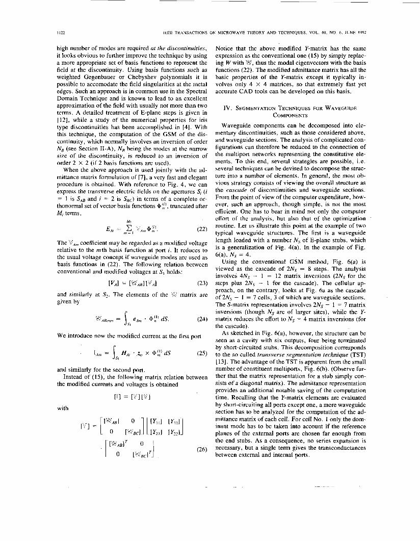
Waveguide components can be decomposed into ele- mentary discontinuities, such as those considered above, and waveguide sections. The analysis of complicated con- figurations can therefore be reduced to the connection of the multiport networks representing the constitutive ele- ments. To this end, several strategies are possible, i.e. several techniques can be devised to decompose the struc- ture into a number of elements. In general, the most ob- vious strategy consists of viewing the overall structure as the cascade of discontinuities and waveguide sections. From the point of view of the computer expenditure, how- ever, such an approach, though simple, is not the most efficient. One has to bear in mind not only the computer effort of the analysis, but also that of the optimization routine. Let us illustrate this point at the example of two typical waveguide structures. The first is a waveguide length loaded with a number N, of E-plane stubs, which is a generalization of Fig. 4(a). In the example of Fig. 6(a), Ns = 4.
Using the conventional GSM method, Fig. 6(a) is viewed as the cascade of 2Ns = 8 steps. The analysis involves 4Ns - 1 = 12 matrix inversions (2Ns for the steps plus 2Ns - 1 for the cascade). The cellular ap- proach, on the contrary, looks at Fig. 6a as the cascade of 2Ns - I = 7 cells, 3 of which are waveguide sections. The S-matrix representation involves 2Ns - 1 = 7 matrix inversions (though Ns are of larger sites), while the Y- matrix reduces the effort to Ns = 4 matrix inversions (for the cascade).
As sketched in Fig. 6(a), however, the structure can be seen as a cavity with six outputs, four being terminated by short-circuited stubs. This decomposition corresponds to the so called transverse segmentation technique (TST) [ 131. The advantage of the TST is apparent from the small number of constituent multiports, Fig. 6(b). (Observe fur- ther that the matrix representation for a stub simply con- sists of a diagonal matrix). The admittance representation provides an additional notable saving of the computation time. Recalling that the Y-matrix elements are evaluated by short-circuiting all ports except one, a mere waveguide section has to be analyzed for the computation of the ad- mittance matrix of each cell. For cell No. 1 only the dom- inant mode has to be taken into account if the reference planes of the external ports are chosen far enough from the end stubs. As a consequence, no series expansion is necessary, but a single term gives the transconductances between external and internal ports.
1
ALESSANDRI et al . : COMPUTER-AIDED DESIGN OF BEAM FORMING NETWORKS
__
I I23
1
(b) Fig. 6. (a) Longitudinal cross section of a stub loaded waveguide. (b)
Equivalent network corresponding to the transverse segmentation.
1
Z4!i!,$*
2
3
4
5
6
7
8
3 r l
43 (b)
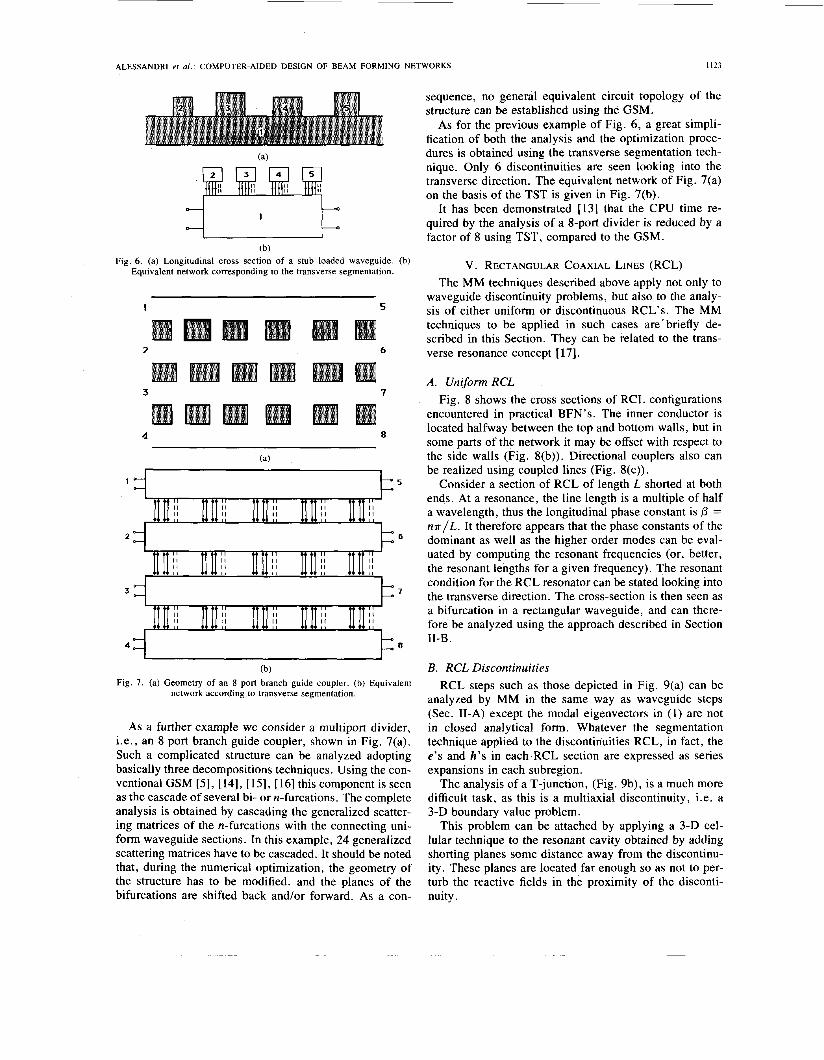
Fig. 7 . (a) Geometry of an 8 port branch guide coupler. (b) Equivalent network according to transverse segmentation.
As a further example we consider a multiport divider, i.e., an 8 port branch guide coupler, shown in Fig. 7(a). Such a complicated structure can be analyzed adopting basically three decompositions techniques. Using the con- ventional GSM [ 5 ] , [ 141, [ 151, [ 161 this component is seen as the cascade of several bi- or n-furcations. The complete analysis is obtained by cascading the generalized scatter- ing matrices of the n-furcations with the connecting uni- form waveguide sections. In this example, 24 generalized scattering matrices have to be cascaded. It should be noted that, during the numerical optimization, the geometry of the structure has to be modified. and the planes of the bifurcations are shifted back and/or forward. As a con-
sequence, no general equivalent circuit topology of the structure can be established using the GSM.
As for the previous example of Fig. 6, a great simpli- fication of both the analysis and the optimization proce- dures is obtained using the transverse segmentation tech- nique. Only 6 discontinuities are seen looking into the transverse direction. The equivalent network of Fig. 7(a) on the basis of the TST is given in Fig. 7(b).
It has been demonstrated [13] that the CPU time re- quired by the analysis of a 8-port divider is reduced by a factor of 8 using TST, compared to the GSM.
V. RECTANGULAR COAXIAL LINES (RCL) The MM techniques described above apply not only to
waveguide discontinuity problems, but also to the analy- sis of either uniform or discontinuous R C L ’ s . The MM techniques to be applied in such cases are‘briefly de- scribed in this Section. They can be related to the trans- verse resonance concept [ 171.
A . Uniform RCL Fig. 8 shows the cross sections of RCL configurations
encountered in practical BFN’s. The inner conductor is located halfway between the top and bottom walls, but in some parts of the network it may be offset with respect to the side walls (Fig. S(b)). Directional couplers also can be realized using coupled lines (Fig. 8(c)).
Consider a section of RCL of length L shorted at both ends. At a resonance, the line length is a multiple of half a wavelength, thus the longitudinal phase constant is 0 = n n / L . It therefore appears that the phase constants of the dominant as well as the higher order modes can be eval- uated by computing the resonant frequencies (or, better, the resonant lengths for a given frequency). The resonant condition for the RCL resonator can be stated looking into the transverse direction. The cross-section is then seen as a bifurcation in a rectangular waveguide, and can there- fore be analyzed using the approach described in Section II-B.
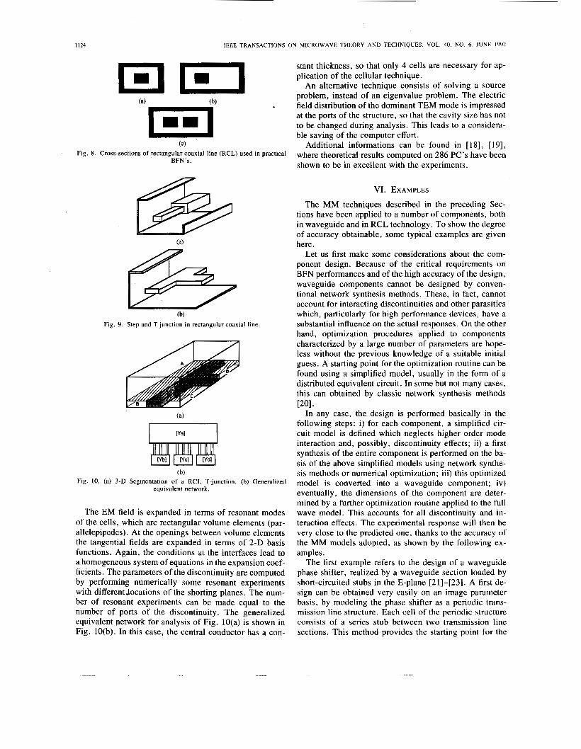
B. RCL Discontinuities RCL steps such as those depicted in Fig. 9(a) can be
analyzed by MM in the same way as waveguide steps (Sec. II-A) except the modal eigenvectors in (1) are not in closed analytical form. Whatever the segmentation technique applied to the discontinuities RCL, in fact, the e’s and h’s in each RCL section are expressed as series expansions in each subregion.
The analysis of a T-junction, (Fig. 9b), is a much more difficult task, as this is a multiaxial discontinuity, i.e. a 3-D boundary value problem.
This problem can be attached by applying a 3-D cel- lular technique to the resonant cavity obtained by adding shorting planes some distance away from the discontinu- ity. These planes are located far enough so as not to per- turb the reactive fields in the proximity of the disconti- nuity.
1 I24 IEEE TRANSACTIONS ON MICROWAVE THEORY AND TECHNIQUES, VOL. 40, NO. 6. JUNE 1992
1111 (C)
Fig. 8. Cross-sections of rectangular coaxial line (RCL) used in practical BFN’s.
(b) Fig. 9 . Step and T junction in rectangular coaxial line.
(b)
equivalent network. Fig. IO. (a) 3-D Segmentation of a RCL T-junction. (b) Generalized
The EM field is expanded in terms of resonant modes of the cells, which are rectangular volume elements (par- allelepipedes). At the openings between volume elements the tangential fields are expanded in terms of 2-D basis functions. Again, the conditions at the interfaces lead to a homogeneous system of equations in the expansion coef- ficients. The parameters of the discontinuity are computed by performing numerically some resonant experiments with differentlocations of the shorting planes. The num- ber of resonant experiments can be made equal to the number of ports of the discontinuity. The generalized equivalent network for analysis of Fig. 10(a) is shown in Fig. 10(b). In this case, the central conductor has a con-
stant thickness, so that only 4 cells are necessary for ap- plication of the cellular technique.
An alternative technique consists of solving a source problem, instead of an eigenvalue problem. The electric field distribution of the dominant TEM mode is impressed at the ports of the structure, so that the cavity size has not to be changed during analysis. This leads to a considera- ble saving of the computer effort.
Additional informations can be found in [18], [19], where theoretical results computed on 286 PC’s have been shown to be in excellent with the experiments.
VI. EXAMPLES
The MM techniques described in the preceding Sec- tions have been applied to a number of components, both in waveguide and in RCL technology. To show the degree of accuracy obtainable, some typical examples are given here.
Let us first make some considerations about the com- ponent design. Because of the critical requirements on BFN performances and of the high accuracy of the design, waveguide components cannot be designed by conven- tional network synthesis methods. These, in fact, cannot account for interacting discontinuities and other parasitics which, particularly for high performance devices, have a substantial influence on the actual responses. On the other hand, optimization procedures applied to components characterized by a large number of parameters are hope- less without the previous knowledge of a suitable initial guess. A starting point for the optimization routine can be found using a simplified model, usually in the form of a distributed equivalent circuit. In some but not many cases, this can obtained by classic network synthesis methods
In any case, the design is performed basically in the following steps: i) for each component, a simplified cir- cuit model is defined which neglects higher order mode interaction and, possibly, discontinuity effects; ii) a first synthesis of the entire component is performed on the ba- sis of the above simplified models using network synthe- sis methods or numerical optimization; iii) this optimized model is converted into a waveguide component; iv) eventually, the dimensions of the component are deter- mined by a further optimization routine applied to the full wave model. This accounts for all discontinuity and in- teraction effects. The experimental response will then be very close to the predicted one, thanks to the accuracy of the MM models adopted, as shown by the following ex- amples.
The first example refers to the design of a waveguide phase shifter, realized by a waveguide section loaded by short-circuited stubs in the E-plane [21]-[23]. A first de- sign can be obtained very easily on an image paramekr basis, by modeling the phase shifter as a periodic trans- mission line structure. Each cell of the periodic structure consists of a series stub between two transmission line sections. This method provides the starting point for the
P O I *
ALESSANDRI er al . : COMPUTER-AIDED DESIGN OF BEAM FORMING NETWORKS
45-
f f l - a, 0 -
0 - a, V
2 -
-45- .- c - ffl
a, ffl 9 -90-
I I25
experiment theory starting point
h L ’,’
-135 105 110 1 1 5 1 2 0 1 2 5 130
frequency GHz (b)
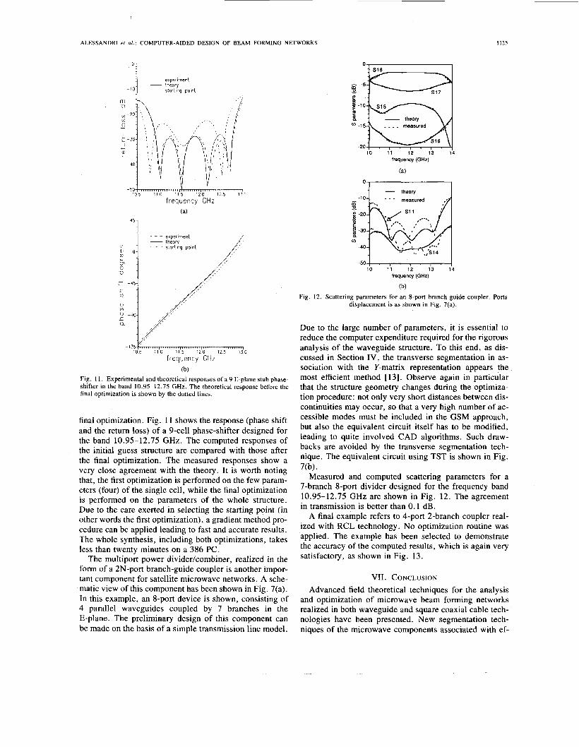
Fig. 1 1 . Experimental and theoretical responses of a 9 E-plane stub phase- shifter in the band 10.95-12.75 GHz. The theoretical response before the final optimization is shown by the dotted lines.
final optimization. Fig. 11 shows the response (phase shift and the return loss) of a 9-cell phase-shifter designed for the band 10.95-12.75 GHz. The computed responses of the initial guess structure are compared with those after the final optimization. The measured responses show a very close agreement with the theory. It is worth noting that, the first optimization is performed on the few param- eters (four) of the single cell, while the final optimization is performed on the parameters of the whole structure. Due to the care exerted in selecting the starting point (in other words the first optimization), a gradient method pro- cedure can be applied leading to fast and accurate results. The whole synthesis, including both optimizations, takes less than twenty minutes on a 386 PC.
The multiport power dividerkombiner, realized in the form of a 2N-port branch-guide coupler is another impor- tant component for satellite microwave networks. A sche- matic view of this component has been shown in Fig. 7(a). In this example, an 8-port device is shown, consisting of 4 parallel waveguides coupled by 7 branches in the E-plane. The preliminary design of this component can be made on the basis of a simple transmission line model.
0 .
frequency (GHz)
(a)
E !! -30
(I)
-40
-50-1 10 11 12 13 14
frequency (GHz)
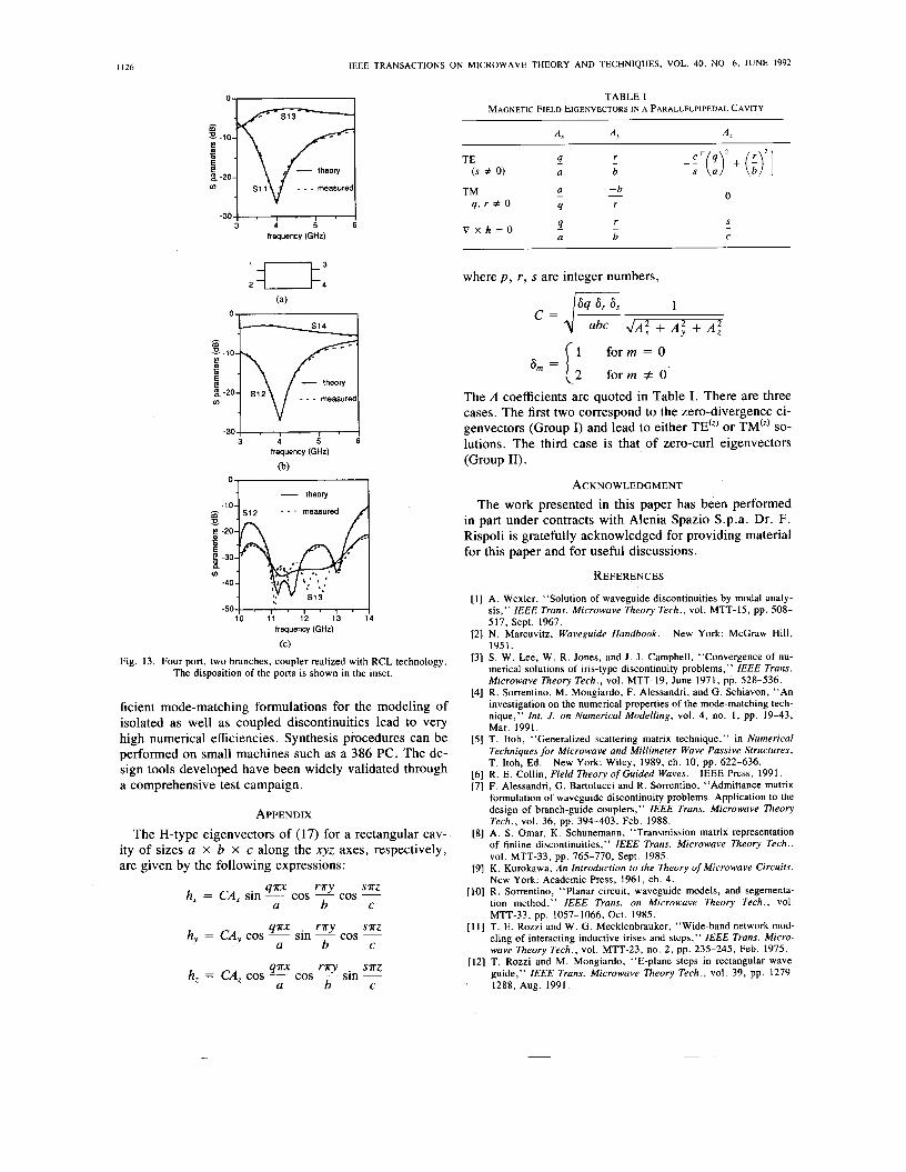
(b) Fig. 12. Scattering parameters for an 8-port branch guide coupler. Ports
displacement is as shown in Fig. 7(a).
Due to the large number of parameters, it is essential to reduce the computer expenditure required for the rigorous analysis of the waveguide structure. To this end, as dis- cussed in Section IV, the transverse segmentation in as- sociation with the Y-matrix representation appears the most efficient method [13]. Observe again in particular that the structure geometry changes during the optimiza- tion procedure: not only very short distances between dis- continuities may occur, so that a very high number of ac- cessible modes must be included in the GSM approach, but also the equivalent circuit itself has to be modified, leading to quite involved CAD algorithms. Such draw- backs are avoided by the transverse segmentation tech- nique. The equivalent circuit using TST is shown in Fig.
Measured and computed scattering parameters for a 7-branch 8-port divider designed for the frequency band 10.95-12.75 GHz are shown in Fig. 12. The agreement in transmission is better than 0.1 dB.
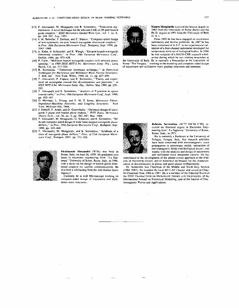
A final example refers to 4-port 2-branch coupler real- ized with RCL technology. No optimization routine was applied. The example has been selected to demonstrate the accuracy of the computed results, which is again very satisfactory, as shown in Fig. 13.
7@).
VII. CONCLUSION Advanced field theoretical techniques for the analysis
and optimization of microwave beam forming networks realized in both waveguide and square coaxial cable tech- nologies have been presented. New segmentation tech- niques of the microwave components associated with ef-
I I26 IEEE TRANSACTIONS ON MICROWAVE THEORY AND TECHNIQUES, VOL. 40. NO. 6. JUNE 1992
g -20 fn measured
- 3 O I I
frequency (GHz)
theory
measured
E
frequency (GHz)
(b)
- theory
0
measured
i! -30 I fn
-40 513’
-50 i o 1 1 12 13 14
frequency (GHz)
(C) Fig. 13. Four port, two branches, coupler realized with RCL technology.
The disposition of the ports is shown in the inset.
ficient mode-matching formulations for the modeling of isolated as well as coupled discontinuities lead to very high numerical efficiencies. Synthesis procedures can be performed on small machines such as a 386 PC. The de- sign tools developed have been widely validated through a comprehensive test campaign.
APPENDIX The H-type eigenvectors of (17) for a rectangular cav-
ity of sizes a x b x c along the xyz axes, respectively, are given by the following expressions:
qux ruy suz h, = CA, sin - cos - cos -
a b C
qux ruy suz h, = CA,, cos - sin - cos -
a b C
qux ruy . suz h, = CA, cos - cos - sin -
a b C
TABLE I MAGNETIC FIELD EIGENVECTORS I N A PARALLELPIPEDAL CAVITY
9 V x h = O a
r b -
.’[($ + ($1 0
S
C -
where p, r , s are integer numbers,
1 form = 0
\2 form + 0’ 6, =
The A coefficients are quoted in Table I. There are three cases. The first two correspond to the zero-divergence ei- genvectors (Group I) and lead to either TE“’ or TM“’ so- lutions. The third case is that, of zero-curl eigenvectors (Group 11).
ACKNOWLEDGMENT The work presented in this paper has been performed
in part under contracts with Alenia Spazio S.p.a. Dr. F. Rispoli is gratefully acknowledged for providing material for this paper and for useful discussions.
REFERENCES
[ I ] A. Wexler, “Solution of waveguide discontinuities by modal analy- sis,’’ IEEE Trans. Microwave Theory Tech., vol. MTT-15, pp. 508- 517, Sept. 1967.
[2] N. Marcuvitz, Waveguide Handbook. New York: McGraw Hill, 1951.
[3] S. W. Lee, W. R. Jones, and J . J . Campbell, “Convergence of nu- merical solutions of iris-type discontinuity problems,” IEEE Trans. Microwave Theory Tech., vol. MTT-19, June 1971, pp. 528-536.
[4] R. Sorrentino, M. Mongiardo, F. Alessandri, and G. Schiavon, “An investigation on the numerical properties of the mode-matching tech- nique,” Int. J. on Numerical Modelling, vol. 4 , no. 1, pp. 19-43, Mar. 1991.
[5] T. Itoh, “Generalized scattering matrix technique,” in Numerical Techniques for Microwave and Millimeter Wave Passive Structures, T. Itoh, Ed. New York: Wiley, 1989, ch. 10, pp. 622-636.
[6] R. E. Collin, Field Theory of Guided Waves. [7] F. Alessandri, G. Bartolucci and R. Sorrentino, “Admittance-matrix
formulation of waveguide discontinuity problems. Application to the design of branch-guide couplers,” IEEE Trans. Microwave Theory Tech., vol. 36, pp. 394-403, Feb. 1988.
[8] A. S. Omar, K. Schunemann, “Transmission matrix representation of finline discontinuities,” IEEE Trans. Microwave Theory Tech., vol. MTT-33, pp. 765-770, Sept. 1985.
[9] K. Kurokawa, An Introduction to the Theory of Microwave Circuits. New York: Academic Press, 1961, ch. 4.
[ 101 R. Sorrentino, “Planar circuit, waveguide models, and segementa- tion method,” IEEE Trans. on Microwave Theory Tech., vol.
[ l l ] T. E. Rozzi and W. G. Mecklenbrauker, “Wide-band network mod- eling of interacting inductive irises and steps,’’ IEEE Trans. Micro- wave Theory Tech., vol. MTT-23, no. 2, pp. 235-245, Feb. 1975.
[12] T. Rozzi and M. Mongiardo, “E-plane steps in rectangular wave- guide,” IEEE Trans. Microwave Theory Tech., vol. 39, pp. 1279-
. 1288, Aug. 1991.
IEEE Press, 1991.
MTT-33, pp. 1057-1066, Oct. 1985.
I127 ALESSANDRI et al.: COMPUTER-AIDED DESIGN OF BEAM FORMING NETWORKS
[I31 F. Alessandn, M. Mongiardo and R. Sorrentino, “Transverse seg- mentation: A novel technique for the efficient CAD of 2N-port branch guide couplers,” IEEE Microwave Guided Wave Lett., vol 1, no. 8 , pp. 204-207, Aug. 1991. (U.K.).
1141 J . M. Rebollar, I. Esteban, and C. Blanco, “Computer-aided design of non-symmetric six-port branch-waveguide directional couplers,” in Proc. 20th European Microwave Conf., Budapest, Sept. 1990, pp. 104 1 - 1048.
[I51 E. Kuhn, H. Schmiedel, and R. Waugh, “Six-port branch-waveguide directional couplers,” in Proc. 16th European Microwave Conf., Dublin, 1986, pp. 453-458.
[I61 P. Carle, “Multiport branch-waveguide couplers with arbitrary power splitting,” in 1989 IEEE MTT-S Inr. Microwave Symp. Dig , Long Beach, CA, pp. 317-320.
[I71 R. Sorrentino, “Transverse resonance technique,” in Numerical Techniques for Microwave and Millimeter Wave Passive Structures, T. Itoh, Ed.
[IS] F. Alessandn, P. Capece, and R. Sorrentino, “Theory and experi- ment on rectangular coaxial line discontinuities and junctions,” in IEEE MTT-S Int. Microwave Symp. Dig., Dallas, May 1990, pp. 259- 262.
[I91 F. Alessandri and R. Sorrentino, “Analysis of T-junction in square coaxial cable,” in Proc. 18rh European Microwave Conf.., Sept. 1988,
[20] G Matthaei, L Young, and E. M. T. Jones, Microwave Filters, Impedance-Matching Networks, and Coupling Structures New York: McGraw-Hill, 1964.
[21] 1. Dittloff, F. Amdt, and D. Grauerholtz, “Optimum design of wave- guide E-plane stub-loaded phase shifters,” IEEE Trans. Microwave Theory Tech., vol. 36, no. 3, pp. 582-587, Mar. 1988.
1221 F. Alessandn. M. Moneiardo. G. Schiavon. and R Sorrentino. “Ef-
Mauro Mongiardo received the Doctor degree in 1983 from the University of Rome (Italy) and the Ph.D. degree in 1991 from the University of Bath
From 1983 he has been engaged on microwave radiometry and inverse problems. In 1987 he has been consultant of E.S.P. in the experimental val- idation of a four-channel radiometer developed for temperature retrieval of biological bodies. In 1988 he was recipient of a NATO-CNR research schol- arship dunng which he was visiting researcher at
the University of Bath. He is currently a Researcher at the University of Rome “Tor Vergata,” working in the modeling and computer-aided design of microwave and millimeter wave guiding structures and antennas.
New York: Wiley, 1989, ch. 11, pp. 637-696
pp. 162-167.
. - ficient computer aided &sign of wide-band stepped waveguide phase- shifters,” in Proc. 20th European Microwave Conf,, Budapest, Sept.
[23] F. Alessandri, M. Mongiardo, and R. Sorrentino, “Synthesis of a class of waveguide phase shifters,” Proc. of 21th European Micro- wave Conf., Stuttgart, 1991, pp. 321-326.
1990, pp. 463-468.
Ferdinand0 Alessandri (M’91) was born in Rome, Italy, on June 26, 1959. He graduated cum laude in electronic engineering from “La Sap- ienza” University of Rome, Rome, Italy, in 1986, with a thesis on the design of branch-guide direc- tional couplers for satellite communications. He also held a scholarship from the AS1 (Italian Space Agency).
Currently he is with Microdesign working on computer-aided design of microwave and milli- meter-wave structures.
Roberto Sorrentino (M’77-SM’84-F’90) re- ceived the Doctoral degree in Electronic Engi- neering from “La Sapienza” University of Rome, Rome, Italy, in 1971.
He is currently a Professor at the University of Perugia, Perugia, Italy. His research activities have been concerned with electromagnetic wave propagation in anisotropic media, interaction of electromagnetic fields with biological tissues, and mainly with the analysis and design of microwave and millimeter-wave integrated circuits. He has
contributed to the development of the planar-circuit approach to the anal- ysis of microstrip circuits and to numerical techniques for the characteri- zation of discontinuities in planar and quasi-planar configurations.
Dr. Sorrentino was Chairman of the Middle and South Italy Section (1984-1987). He founded the local MTT/AP Chapter and served as Chap- ter Chairman from 1984 to 1987. He is a member of the Editorial Board of the IEEE TRANSACTIONS ON MICROWAVE THEORY AND TECHNIQUES, of the International Journal on Numerical Modelling, and of the Journal of Elec- tromagnetic Waves and Applications.


![A REVIEW ON COMPUTER AIDED MANUFACTURING FACTORS … · Fig -3: Two Point Incremental Sheet Forming [12] 1.1.3 Computer sheet [22].Aided Manufacturing factors in SPIF (vi) In SPIF](https://img.pdfslide.net/doc/110x75/5e7ee37ca7f6bf2fa315a3f0/a-review-on-computer-aided-manufacturing-factors-fig-3-two-point-incremental-sheet.jpg)