Embed Size (px)
Citation preview
Computer Graphics : Unit - I
T.Rajan Babu / AP / MCA Department of MCA, RGCET
Computer Graphics – Unit 1
Introduction:
Computer Graphics – it is a set of tools to create, manipulate and interact with pictures. Data is
visualized through geometric shapes, colors and textures.
Video Display Devices
The primary output device in a graphics system is a video monitor. The operation of most video
monitors is based on the standard cathode ray tube.
Refresh Cathode-Ray Tubes
Raster Scan Displays
Random-Scan Displays
Color CRT Monitors
Direct-View Storage Tubes
Flat-Panel Displays
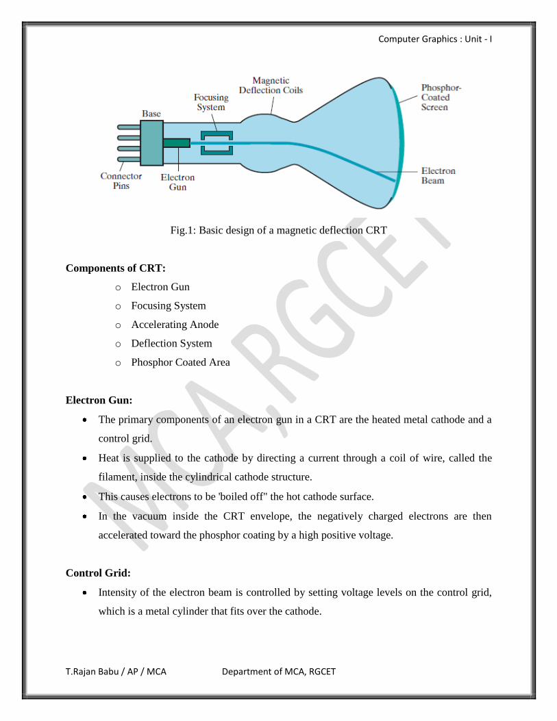
Refresh Cathode-Ray Tubes
A beam of electrons (cathode rays), emitted by an electron gun, passes through focusing
and deflection systems that direct the beam toward specified positions on the phosphor-
coated screen.
The phosphor then emits a small spot of light at each position contacted by the electron
beam.
The light emitted by the phosphor fades very rapidly, some method is needed for
maintaining the screen picture.
One way to keep the phosphor glowing is to redraw the picture repeatedly by quickly
directing the electron beam back over the same points. This type of display is called a
refresh CRT.
Computer Graphics : Unit - I
T.Rajan Babu / AP / MCA Department of MCA, RGCET
Fig.1: Basic design of a magnetic deflection CRT
Components of CRT:
o Electron Gun
o Focusing System
o Accelerating Anode
o Deflection System
o Phosphor Coated Area
Electron Gun:
The primary components of an electron gun in a CRT are the heated metal cathode and a
control grid.
Heat is supplied to the cathode by directing a current through a coil of wire, called the
filament, inside the cylindrical cathode structure.
This causes electrons to be 'boiled off" the hot cathode surface.
In the vacuum inside the CRT envelope, the negatively charged electrons are then
accelerated toward the phosphor coating by a high positive voltage.
Control Grid:
Intensity of the electron beam is controlled by setting voltage levels on the control grid,
which is a metal cylinder that fits over the cathode.
Computer Graphics : Unit - I
T.Rajan Babu / AP / MCA Department of MCA, RGCET
A high negative voltage applied to the control grid will shut off the beam by repelling
electrons and stopping them from passing through the small hole at the end of the control
grid structure.
A smaller negative voltage on the control grid simply decreases the number of electrons
passing through it.
The amount of light emitted by the phosphor coating depends on the number of electrons
striking the screen.
We control the brightness of a display by varying the voltage on the control grid.
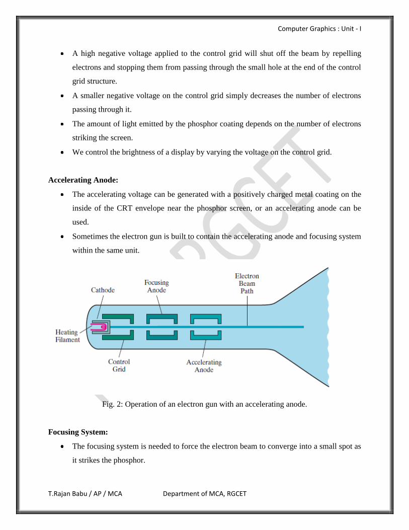
Accelerating Anode:
The accelerating voltage can be generated with a positively charged metal coating on the
inside of the CRT envelope near the phosphor screen, or an accelerating anode can be
used.
Sometimes the electron gun is built to contain the accelerating anode and focusing system
within the same unit.
Fig. 2: Operation of an electron gun with an accelerating anode.
Focusing System:
The focusing system is needed to force the electron beam to converge into a small spot as
it strikes the phosphor.
Computer Graphics : Unit - I
T.Rajan Babu / AP / MCA Department of MCA, RGCET
Otherwise, the electrons would repel each other, and the beam would spread out as it
approaches the screen. Focusing is accomplished with either electric or magnetic fields.
Electrostatic focusing is commonly used in television and computer graphics monitors.
With electrostatic focusing, the electrons beam passes through a positively charged Metal
cylinder that forms an electrostatic lens.
The action of the electrostatic lens focuses the electron beam at the center of the screen.
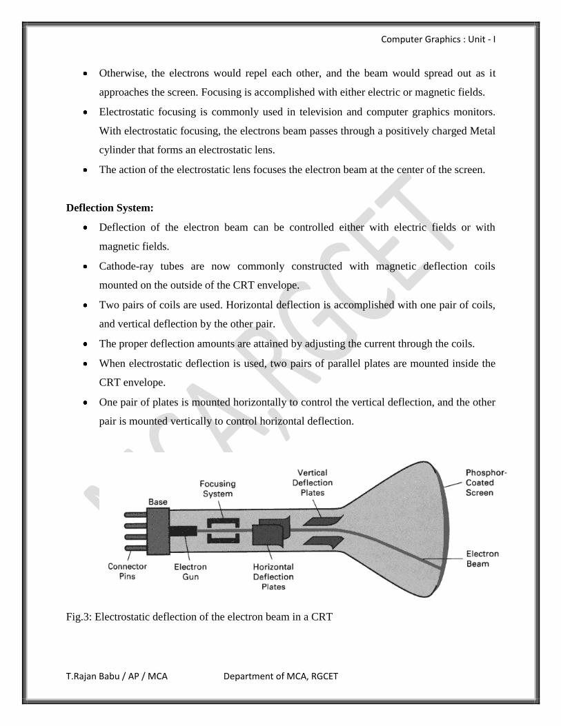
Deflection System:
Deflection of the electron beam can be controlled either with electric fields or with
magnetic fields.
Cathode-ray tubes are now commonly constructed with magnetic deflection coils
mounted on the outside of the CRT envelope.
Two pairs of coils are used. Horizontal deflection is accomplished with one pair of coils,
and vertical deflection by the other pair.
The proper deflection amounts are attained by adjusting the current through the coils.
When electrostatic deflection is used, two pairs of parallel plates are mounted inside the
CRT envelope.
One pair of plates is mounted horizontally to control the vertical deflection, and the other
pair is mounted vertically to control horizontal deflection.
Fig.3: Electrostatic deflection of the electron beam in a CRT
Computer Graphics : Unit - I
T.Rajan Babu / AP / MCA Department of MCA, RGCET
Phosphor Coating:
Spots of light are produced on the screen by the transfer of the CRT beam energy to the
phosphor.
When the electrons in the beam collide with the phosphor coating, they are stopped and
their kinetic energy is absorbed by the phosphor.
Part of the beam energy is converted by friction into heat energy, and the remainder
causes electrons in the phosphor atoms to move up to higher quantum-energy levels.
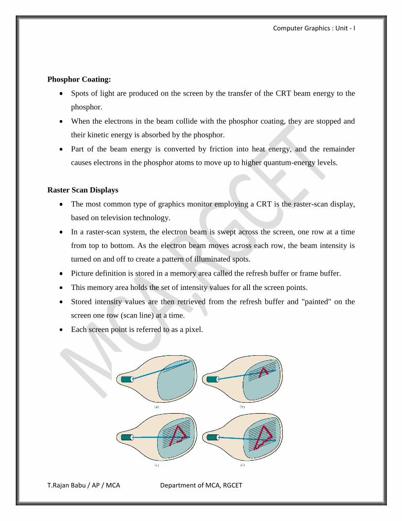
Raster Scan Displays
The most common type of graphics monitor employing a CRT is the raster-scan display,
based on television technology.
In a raster-scan system, the electron beam is swept across the screen, one row at a time
from top to bottom. As the electron beam moves across each row, the beam intensity is
turned on and off to create a pattern of illuminated spots.
Picture definition is stored in a memory area called the refresh buffer or frame buffer.
This memory area holds the set of intensity values for all the screen points.
Stored intensity values are then retrieved from the refresh buffer and "painted" on the
screen one row (scan line) at a time.
Each screen point is referred to as a pixel.
Computer Graphics : Unit - I
T.Rajan Babu / AP / MCA Department of MCA, RGCET
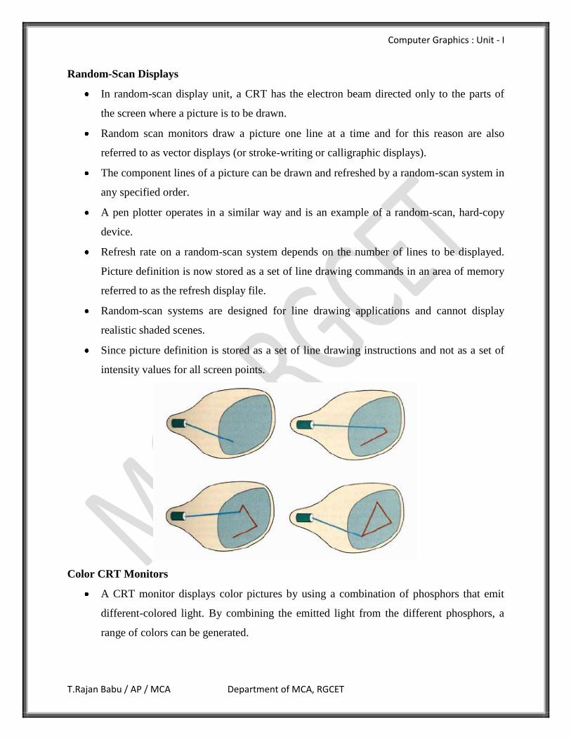
Random-Scan Displays
In random-scan display unit, a CRT has the electron beam directed only to the parts of
the screen where a picture is to be drawn.
Random scan monitors draw a picture one line at a time and for this reason are also
referred to as vector displays (or stroke-writing or calligraphic displays).
The component lines of a picture can be drawn and refreshed by a random-scan system in
any specified order.
A pen plotter operates in a similar way and is an example of a random-scan, hard-copy
device.
Refresh rate on a random-scan system depends on the number of lines to be displayed.
Picture definition is now stored as a set of line drawing commands in an area of memory
referred to as the refresh display file.
Random-scan systems are designed for line drawing applications and cannot display
realistic shaded scenes.
Since picture definition is stored as a set of line drawing instructions and not as a set of
intensity values for all screen points.
Color CRT Monitors
A CRT monitor displays color pictures by using a combination of phosphors that emit
different-colored light. By combining the emitted light from the different phosphors, a
range of colors can be generated.
Computer Graphics : Unit - I
T.Rajan Babu / AP / MCA Department of MCA, RGCET
The two basic techniques for producing color displays with a CRT are the beam-
penetration method and the shadow-mask method.
The beam-penetration method for displaying color pictures has been used with
random-scan monitors. Two layers of phosphor, usually red and green, are coated onto
the inside of the CRT screen, and the displayed color depends on how far the electron
beam penetrates into the phosphor layers. A beam of slow electrons excites only the outer
red layer. A beam of very fast electrons penetrates through the red layer and excites the
inner green layer. At intermediate beam speeds, combinations of red and green light are
emitted to show two additional colors, orange and yellow.
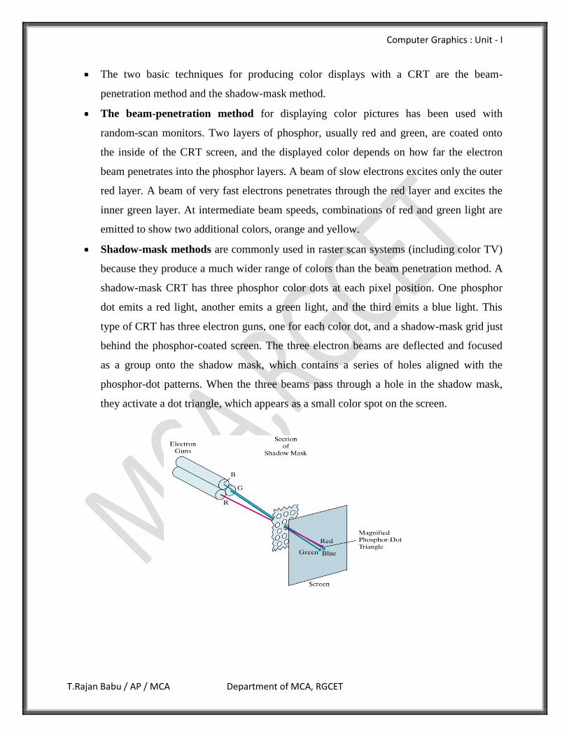
Shadow-mask methods are commonly used in raster scan systems (including color TV)
because they produce a much wider range of colors than the beam penetration method. A
shadow-mask CRT has three phosphor color dots at each pixel position. One phosphor
dot emits a red light, another emits a green light, and the third emits a blue light. This
type of CRT has three electron guns, one for each color dot, and a shadow-mask grid just
behind the phosphor-coated screen. The three electron beams are deflected and focused
as a group onto the shadow mask, which contains a series of holes aligned with the
phosphor-dot patterns. When the three beams pass through a hole in the shadow mask,
they activate a dot triangle, which appears as a small color spot on the screen.
Computer Graphics : Unit - I
T.Rajan Babu / AP / MCA Department of MCA, RGCET
Direct-View Storage Tubes
A direct-view storage tube (DVST) stores the picture information as a charge distribution
just behind the phosphor-coated screen. Two electron guns are used in a DVST.
One, the primary gun, is used to store the picture pattern.
The second, the flood gun, maintains the picture display.
A DVST monitor has both disadvantages and advantages compared to the refresh CRT.
Because no refreshing is needed, very complex pictures can be displayed at very high
resolutions without flicker.
Disadvantages of DVST systems are that they ordinarily do not display color and that
selected parts of a picture cannot be erased. To eliminate a picture section, the entire
screen must be erased and the modified picture redrawn.
Flat-Panel Displays
The term Flat-panel display refers to a class of video devices that have reduced volume,
weight, and power requirements compared to a CRT. A significant feature of flat-panel
displays is that they are thinner than CRTs.
We can separate flat-panel displays into two categories: emissive displays and non-
emissive displays. The emissive displays (or emitters) are devices that convert electrical
energy into light. Plasma panels, thin-film electroluminescent displays, and Light-
emitting diodes are examples of emissive displays.
Non-emissive displays use optical effects to convert sunlight or light from some other
source into graphics patterns. The most important example of a non-emissive flat-panel
display is a liquid-crystal device.
Plasma Panels
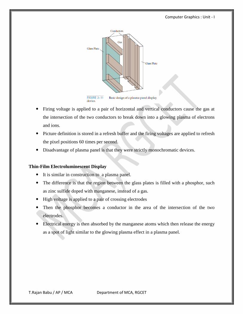
It is also called as Gas-Discharge Display
It is constructed by filling the region between two glass plates with a mixture of gases
that usually includes neon.
Set of vertical conducting ribbons is placed on one glass panel and a set of horizontal
ribbons is built into the other glass panel.
Computer Graphics : Unit - I
T.Rajan Babu / AP / MCA Department of MCA, RGCET
Firing voltage is applied to a pair of horizontal and vertical conductors cause the gas at
the intersection of the two conductors to break down into a glowing plasma of electrons
and ions.
Picture definition is stored in a refresh buffer and the firing voltages are applied to refresh
the pixel positions 60 times per second.
Disadvantage of plasma panel is that they were strictly monochromatic devices.
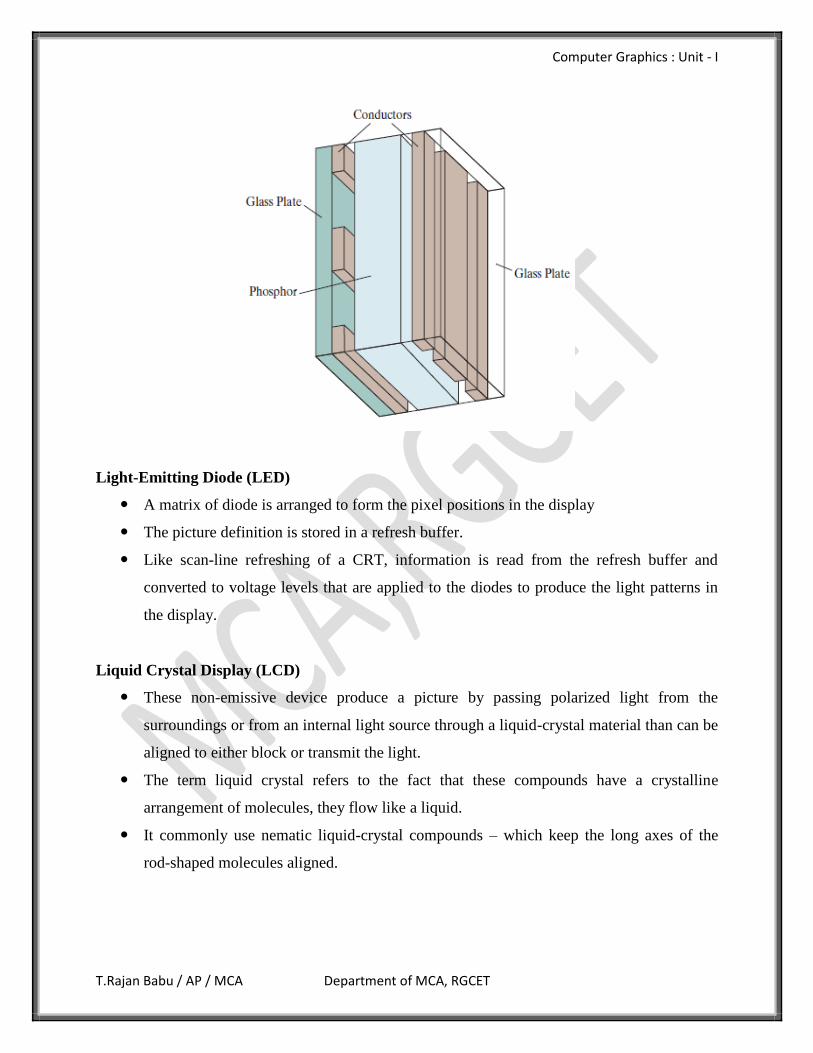
Thin-Film Electroluminescent Display
It is similar in construction to a plasma panel.
The difference is that the region between the glass plates is filled with a phosphor, such
as zinc sulfide doped with manganese, instead of a gas.
High voltage is applied to a pair of crossing electrodes
Then the phosphor becomes a conductor in the area of the intersection of the two
electrodes.
Electrical energy is then absorbed by the manganese atoms which then release the energy
as a spot of light similar to the glowing plasma effect in a plasma panel.
Computer Graphics : Unit - I
T.Rajan Babu / AP / MCA Department of MCA, RGCET
Light-Emitting Diode (LED)
A matrix of diode is arranged to form the pixel positions in the display
The picture definition is stored in a refresh buffer.
Like scan-line refreshing of a CRT, information is read from the refresh buffer and
converted to voltage levels that are applied to the diodes to produce the light patterns in
the display.
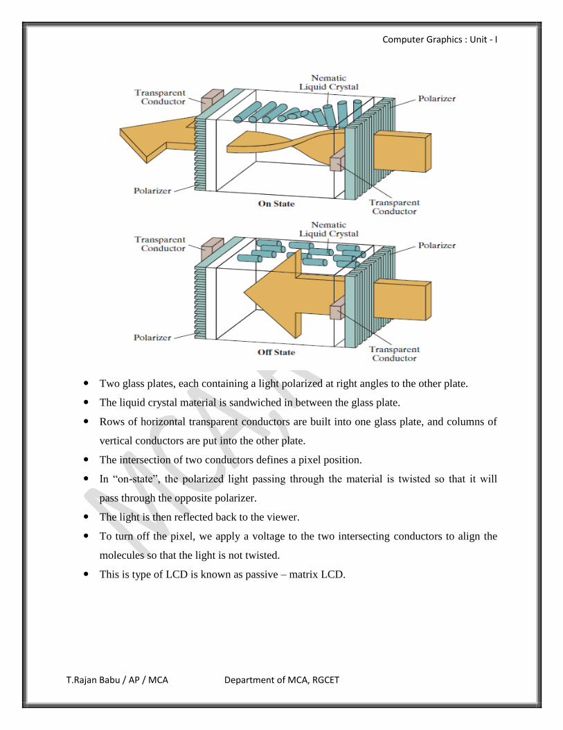
Liquid Crystal Display (LCD)
These non-emissive device produce a picture by passing polarized light from the
surroundings or from an internal light source through a liquid-crystal material than can be
aligned to either block or transmit the light.
The term liquid crystal refers to the fact that these compounds have a crystalline
arrangement of molecules, they flow like a liquid.
It commonly use nematic liquid-crystal compounds – which keep the long axes of the
rod-shaped molecules aligned.
Computer Graphics : Unit - I
T.Rajan Babu / AP / MCA Department of MCA, RGCET
Two glass plates, each containing a light polarized at right angles to the other plate.
The liquid crystal material is sandwiched in between the glass plate.
Rows of horizontal transparent conductors are built into one glass plate, and columns of
vertical conductors are put into the other plate.
The intersection of two conductors defines a pixel position.
In “on-state”, the polarized light passing through the material is twisted so that it will
pass through the opposite polarizer.
The light is then reflected back to the viewer.
To turn off the pixel, we apply a voltage to the two intersecting conductors to align the
molecules so that the light is not twisted.
This is type of LCD is known as passive – matrix LCD.
Computer Graphics : Unit - I
T.Rajan Babu / AP / MCA Department of MCA, RGCET
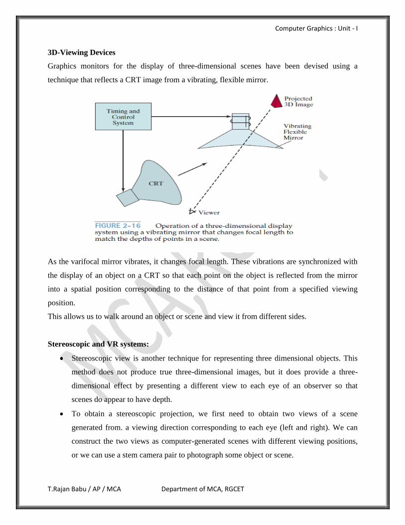
3D-Viewing Devices
Graphics monitors for the display of three-dimensional scenes have been devised using a
technique that reflects a CRT image from a vibrating, flexible mirror.
As the varifocal mirror vibrates, it changes focal length. These vibrations are synchronized with
the display of an object on a CRT so that each point on the object is reflected from the mirror
into a spatial position corresponding to the distance of that point from a specified viewing
position.
This allows us to walk around an object or scene and view it from different sides.
Stereoscopic and VR systems:
Stereoscopic view is another technique for representing three dimensional objects. This
method does not produce true three-dimensional images, but it does provide a three-
dimensional effect by presenting a different view to each eye of an observer so that
scenes do appear to have depth.
To obtain a stereoscopic projection, we first need to obtain two views of a scene
generated from. a viewing direction corresponding to each eye (left and right). We can
construct the two views as computer-generated scenes with different viewing positions,
or we can use a stem camera pair to photograph some object or scene.
Computer Graphics : Unit - I
T.Rajan Babu / AP / MCA Department of MCA, RGCET
When we simultaneous look at the left view with the left eye and the right view with the
right eye, the views merge into a single image and we perceive a scene with depth.
One way to produce a stereoscopic effect is to display each of the two views with a raster
system on alternate refresh cycles. The screen is viewed through glasses, with each lens
designed to act as a rapidly alternating shutter that is synchronized to block out one of the
views. Stereoscopic viewing is also a component in virtual-reality systems, where users
can step into a scene and interact with the environment
A headset containing an optical system to generate the stereoscopic views is commonly
used in conjuction with interactive input devices to locate and manipulate objects in the
scene.
A sensing system in the headset keeps track of the viewer's position, so that the front and
back of objects can be seen as the viewer "walks through" and interacts with the display.
An interactive virtual-reality environment can also be viewed with stereoscopic glasses
and a video monitor, instead of a headset. This provides a means for obtaining a lower
cost virtual-reality system.
Raster Scan and random scan display processor.
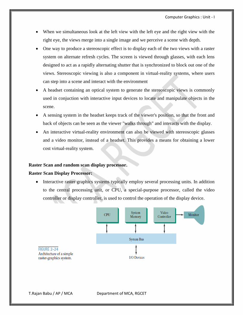
Raster Scan Display Processor:
Interactive raster graphics systems typically employ several processing units. In addition
to the central processing unit, or CPU, a special-purpose processor, called the video
controller or display controller, is used to control the operation of the display device.
Computer Graphics : Unit - I
T.Rajan Babu / AP / MCA Department of MCA, RGCET
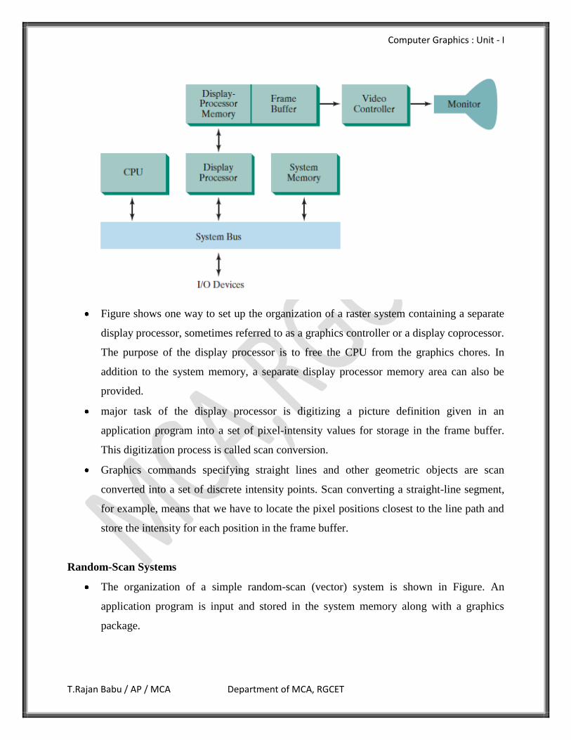
Figure shows one way to set up the organization of a raster system containing a separate
display processor, sometimes referred to as a graphics controller or a display coprocessor.
The purpose of the display processor is to free the CPU from the graphics chores. In
addition to the system memory, a separate display processor memory area can also be
provided.
major task of the display processor is digitizing a picture definition given in an
application program into a set of pixel-intensity values for storage in the frame buffer.
This digitization process is called scan conversion.
Graphics commands specifying straight lines and other geometric objects are scan
converted into a set of discrete intensity points. Scan converting a straight-line segment,
for example, means that we have to locate the pixel positions closest to the line path and
store the intensity for each position in the frame buffer.
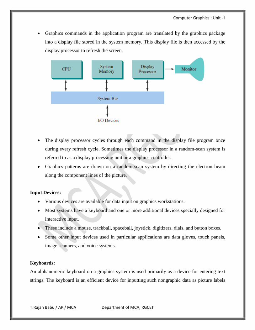
Random-Scan Systems
The organization of a simple random-scan (vector) system is shown in Figure. An
application program is input and stored in the system memory along with a graphics
package.
Computer Graphics : Unit - I
T.Rajan Babu / AP / MCA Department of MCA, RGCET
Graphics commands in the application program are translated by the graphics package
into a display file stored in the system memory. This display file is then accessed by the
display processor to refresh the screen.
The display processor cycles through each command in the display file program once
during every refresh cycle. Sometimes the display processor in a random-scan system is
referred to as a display processing unit or a graphics controller.
Graphics patterns are drawn on a random-scan system by directing the electron beam
along the component lines of the picture.
Input Devices:
Various devices are available for data input on graphics workstations.
Most systems have a keyboard and one or more additional devices specially designed for
interactive input.
These include a mouse, trackball, spaceball, joystick, digitizers, dials, and button boxes.
Some other input devices used in particular applications are data gloves, touch panels,
image scanners, and voice systems.
Keyboards:
An alphanumeric keyboard on a graphics system is used primarily as a device for entering text
strings. The keyboard is an efficient device for inputting such nongraphic data as picture labels
Computer Graphics : Unit - I
T.Rajan Babu / AP / MCA Department of MCA, RGCET
associated with a graphics display. Keyboards cal also be provided with features to facilitate
entry of screen coordinates, menu selections, or graphics functions.
Cursor-control keys and function keys are common features on general purpose keyboards.
Function keys allow users to enter frequently used operations in a single keystroke, and cursor-
control keys can be used to select displayed objects or coordinate positions by positioning the
screen cursor.
Mouse:
A mouse is small hand-held box used to position the screen cursor. Wheels or rollers on the
bottom of the mouse can be used to record the amount and direction of movement. Another
method for detecting mouse motion is with an optical sensor. For these systems, the mouse is
moved over a special mouse pad that has a grid of horizontal and vertical lines. The optical
sensor detects movement across the lines in the grid. Since a mouse can be picked up and put
down at another position without change in cursor movement, it is used for making relative
change in the position of the screen cursor. One, two, or three buttons are usually included on the
top of the mouse for signaling the execution of some operation, such as recording cursor position
or invoking a function.
Trackball:
As the name implies, a trackball is a ball that can be rotated with the fingers or palm of the hand,
to produce screen-cursor movement. Potentiometers, attached to the ball, measure the amount
and direction of rotation. Trackballs are often mounted on keyboards or other devices such as the
Z mouse. While a trackball is a two-dimensional positioning device.
Spaceball:
A spaceball provides six degrees of freedom. Unlike the trackball, a spaceball does not actually
move. Strain gauges measure the amount of pressure applied to the spaceball to provide input for
spatial positioning and orientation as the ball is pushed or pulled in various directions. Spaceballs
are used for three-dimensional positioning and selection operations in virtual-reality systems,
modeling, animation, CAD, and other applications.
Computer Graphics : Unit - I
T.Rajan Babu / AP / MCA Department of MCA, RGCET
Joysticks:
A joystick consists of a small, vertical lever (called the stick) mounted on a base that is used to
steer the screen cursor around. Most joysticks select screen positions with actual stick
movement; others respond to pressure on the stick. Some joysticks are mounted on a keyboard;
others function as stand-alone units.
The distance that the stick is moved in any direction from its center position corresponds to
screen-cursor movement in that direction. Potentiometers mounted at the base of the joystick
measure the amount of movement, and springs return the stick to the center position when it is
released. One or more buttons can be programmed to act as input switches to signal certain
actions once a screen position has been selected.
Data Glove:
A data glove can be used to grasp a "virtual" object. The glove is constructed with a series of
sensors that detect hand and finger motions. Electromagnetic coupling between transmitting
antennas and receiving antennas is used to provide information about the position and orientation
of the hand.
The transmitting and receiving antennas can each be structured as a set of three mutually
perpendicular coils, forming a three-dimensional Cartesian coordinate system. Input from the
glove can be used to position or manipulate objects in a virtual scene. A two-dimensional
projection of the scene can be viewed on a video monitor, or a three-dimensional projection can
be viewed with a headset.
Digitizers:
A common device for drawing, painting, or interactively selecting coordinate positions on an
object is a digitizer. These devices can be used to input coordinate values in either a two-
dimensional or a three-dimensional space.
Typically, a digitizer is used to scan over a drawing or object and to input a set of discrete
coordinate positions, which can be joined with straight-line segments to approximate the curve or
surface shapes. One type of digitizer is the graphics tablet, which is used to input two-
Computer Graphics : Unit - I
T.Rajan Babu / AP / MCA Department of MCA, RGCET
dimensional coordinates by activating a hand cursor or stylus at selected positions on a flat
surface.
Image Scanners:
Drawings, graphs, color and black-and-white photos, or text can be stored for computer
processing with an image scanner by passing an optical scanning mechanism over the
information to be stored. The gradations of gray scale or color are then recorded and stored in an
array. Once we have the internal representation of a picture, we can apply transformations to
rotate, scale, or crop the picture to a particular screen area.
Touch Panels:
Touch panels allow displayed objects or screen positions to be selected with the touch of a
finger. A typical application of touch panels is for the selection of processing options that are
represented with graphical icons.
Optical touch panels employ a line of infrared light-emitting diodes (LEDs) along one vertical
edge and along one horizontal edge of the frame. The opposite vertical and horizontal edges
contain light detectors.
These detectors are used to record which beams are interrupted when the panel is touched. The
two crossing beams that are interrupted identify the horizontal and vertical coordinates of the
screen position selected.
Light Pens:
Pencil-shaped devices are used to select screen positions by detecting the light coming from
points on the CRT screen. They are sensitive to the short burst of light emitted from the phosphor
coating at the instant the electron beam strikes a particular point. Other Light sources, such as the
background light in the room, are usually not detected
by a light pen. An activated light pen, pointed at a spot on the screen as the electron beam lights
up that spot, generates an electrical pulse that causes the coordinate position of the electron beam
to be recorded. As with cursor-positioning devices, recorded light-pen coordinates can be used to
position an object or to select a processing option.
Computer Graphics : Unit - I
T.Rajan Babu / AP / MCA Department of MCA, RGCET
Voice Systems:
Speech recognizers are used in some graphics workstations as input devices to accept voice
commands The voice-system input can be used to initiate graphics operations or to enter data.
These systems operate by matching an input against a predefined dictionary of words and phrase.
Hard-Copy Devices:
We can obtain hard-copy output for our images in several formats. To put images on
film, we can simply photograph a scene displayed on a video monitor. And we can put
our pictures on paper by directing graphics output to a printer or plotter.
The quality of the pictures obtained from a device depends on dot size and the number of
dots per inch, or Lines per inch, that can be displayed. To produce smooth characters in
printed text strings, higher-quality printers shift dot positions so that adjacent dots
overlap.
Printers produce output by either impact or nonimpact methods.
Impact printers press formed character faces against an inked ribbon onto the paper. A
line printer is an example of an impact device, with the typefaces mounted on bands,
chains, drums, or wheels.
Nonimpact printers and plotters use laser techniques, ink-jet sprays, xerographic
processes (as used in photocopying machines), electrostatic methods, and electrothermal
methods to get images onto paper.
Character impact printers often have a dot-matrix print head containing a rectangular
array of protruding wire pins, with the number of pins depending on the quality of the
printer. Individual characters or graphics patterns are obtained by retracting certain pins
so that the remaining pins form the pattern to be printed.
In a laser device, a laser beam creates a charge distribution on a rotating drum coated
with a photoelectric material, such as selenium. Toner is applied to the drum and then
transferred to paper.
Ink-jet methods produce output by squirting ink in horizontal rows across a roll of paper
wrapped on a drum. The electrically charged ink stream is deflected by an electric field to
produce dot-matrix patterns.
Computer Graphics : Unit - I
T.Rajan Babu / AP / MCA Department of MCA, RGCET
An electrostatic device places a negative charge on the paper, one complete row at a
time along the length of the paper. Then the paper is exposed to a toner. The toner is
positively charged and so is attracted to the negatively charged areas, where it adheres to
produce the specified output.
Electrothermal methods use heat in a dot-matrix print head to output patterns on heat
sensitive paper.
We can get limited color output on an impact printer by using different colored ribbons.