Embed Size (px)
Citation preview
COMPUTER PROGRAMMING I
Understand Problem Solving Tools to Design Programming
Solutions
2
Objective/Essential Standard
Essential Standard: 2.00 Understand the Solution Development Process
Indicator: 2.02 Understand Problem Solving Tools to Design Programming Solutions. (3%)
Problem Solving Tools
Programs are created to solve problems.
A solution must be designed prior to coding.
One method of designing a solution to a problem is to create an algorithm.
Algorithms
An algorithm is a list of steps to solve a problem written in plain English.
Steps to solve a problem are written out and numbered in the order in which they should be executed.
They should be as extensive as necessary to outline the solution.
Your algorithm is not only going to tell your program what to do but how to do it.
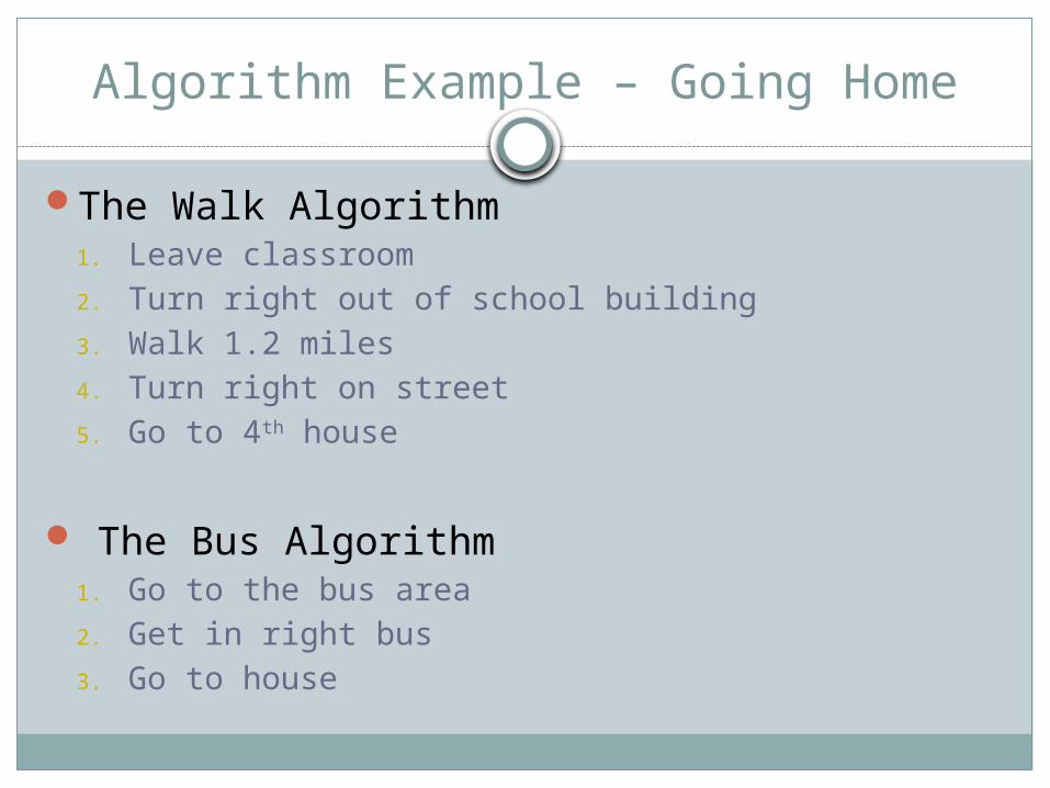
Algorithm Example – Going Home
The Walk Algorithm1. Leave classroom2. Turn right out of school building3. Walk 1.2 miles4. Turn right on street5. Go to 4th house
The Bus Algorithm1. Go to the bus area2. Get in right bus3. Go to house
Algorithms
Both algorithms, and others that accomplish the same task (of getting you home).
There are advantages and disadvantages associated with each option.
You have to consider each option and its advantages/disadvantages before you choose the algorithm you want to continue developing into your program.
Programming Algorithm Example
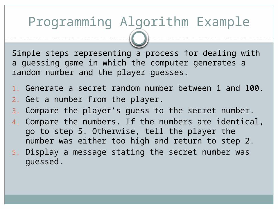
Simple steps representing a process for dealing with a guessing game in which the computer generates a random number and the player guesses.
1. Generate a secret random number between 1 and 100.
2. Get a number from the player.3. Compare the player’s guess to the secret number.4. Compare the numbers. If the numbers are identical,
go to step 5. Otherwise, tell the player the number was either too high and return to step 2.
5. Display a message stating the secret number was guessed.
Pseudocode
Pseudocode is a mix of English language and code that represents what you want your program to do.
It helps you determine how you want the program to work as well as what variables and methods/functions you will want to include.
Developing pseudocode will help you work through your logic, reducing the number of errors and potential re-writes you will have to do.
Pseudocode Example
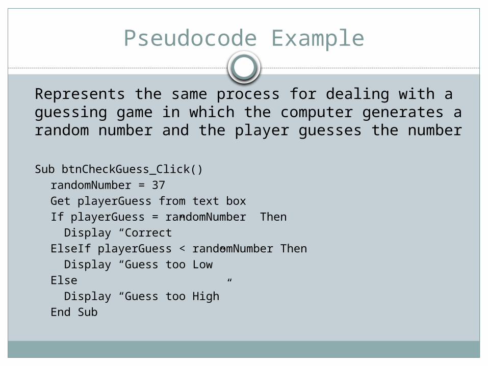
Represents the same process for dealing with a guessing game in which the computer generates a random number and the player guesses the number
Sub btnCheckGuess_Click()randomNumber = 37Get playerGuess from text boxIf playerGuess = randomNumber Then
Display “Correct”ElseIf playerGuess < randomNumber Then
Display “Guess too Low”Else
Display “Guess too High”End Sub
Flowchart
A third tool in programming is through the use of a flowchart.
Flowcharts use symbols and text to give a visual representation of a solution to a problem.
The direction of the arrows indicates the flow of the logic.
Flowchart
Flowcharts help the programmer begin to plan the programming project.
They provide a visual representation of the algorithm or process.
They describe the inputs, processes and outputs of the program that are needed to successfully complete the project.
Flowchart Symbols
There are many flowchart programs, however you can also use Microsoft Word to create a flowchart – or just a piece of paper and a pencil.
To create the flowchart, there are different symbols that represent the various parts. We will only use a few of these symbols.
Use lines with arrows to indicate flow of control.
The text in your flowchart symbols is your pseudocode.
Flowchart Symbols
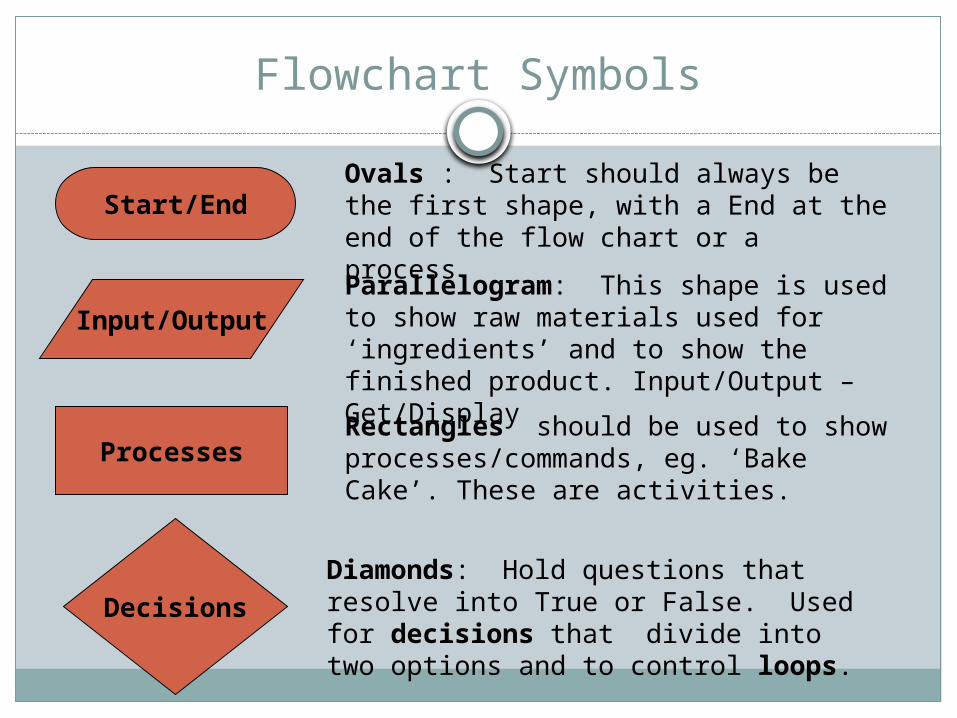
Start/End
Input/Output
Processes
Decisions
Ovals : Start should always be the first shape, with a End at the end of the flow chart or a process.
Parallelogram: This shape is used to show raw materials used for ‘ingredients’ and to show the finished product. Input/Output – Get/Display
Rectangles should be used to show processes/commands, eg. ‘Bake Cake’. These are activities.
Diamonds: Hold questions that resolve into True or False. Used for decisions that divide into two options and to control loops.
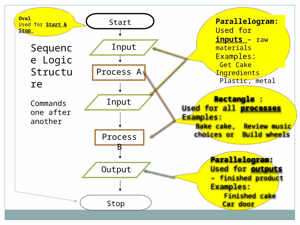
Start
Input
Process A
Output
Stop
OvalUsed for Start & Stop Parallelogram:
Used for inputs – raw materials Examples: Get Cake Ingredients Plastic, metal
Parallelogram: Used for outputs– finished productExamples: Finished cake Car door
Process B
Input Rectangle :Used for all processes Examples: Bake cake, Review music choices or Build wheels
Sequence Logic Structure
Commands one after another
Structured Programming
A technique that has proven to be very effective in solving programs as well as in modifying solutions.
The principles of structured programming are fundamental to procedure-oriented programming.
They are also relevant to object-oriented programming.
Structured Programming
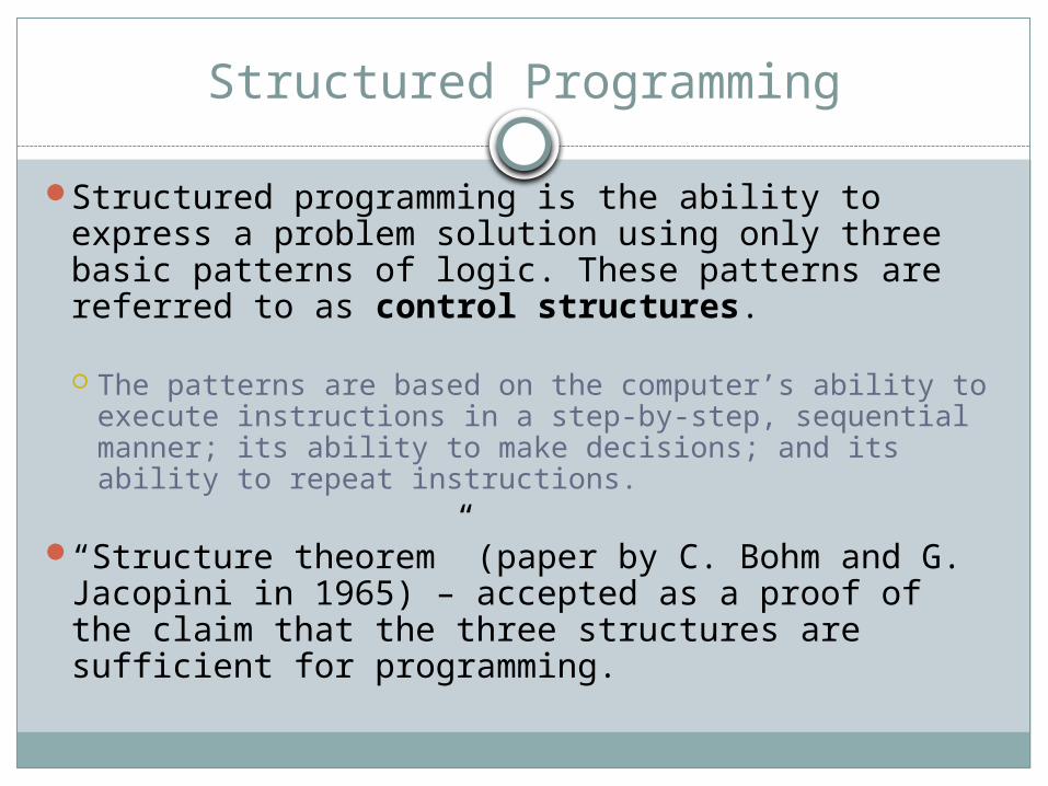
Structured programming is the ability to express a problem solution using only three basic patterns of logic. These patterns are referred to as control structures.
The patterns are based on the computer’s ability to execute instructions in a step-by-step, sequential manner; its ability to make decisions; and its ability to repeat instructions.
“Structure theorem” (paper by C. Bohm and G. Jacopini in 1965) – accepted as a proof of the claim that the three structures are sufficient for programming.
Basic Control Structures
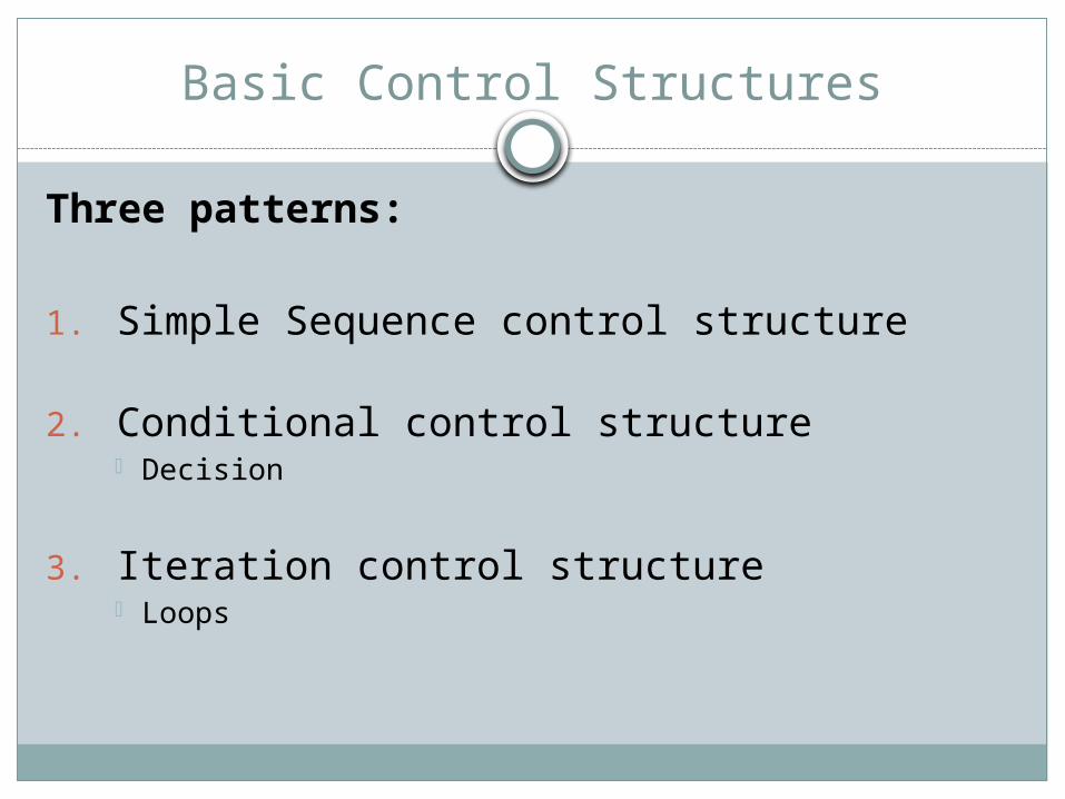
Three patterns:
1. Simple Sequence control structure
2. Conditional control structure Decision
3. Iteration control structure Loops
SIMPLE SEQUENCE Control Structure
Represents the computer’s ability to execute instructions in a step-by-step, sequential manner.
Example: directions to get to the school – steps must be followed sequentially
SIMPLE SEQUENCE Control Structure
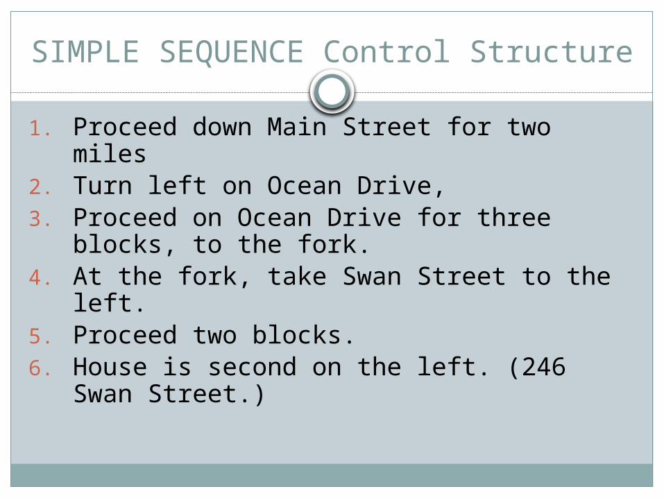
1. Proceed down Main Street for two miles2. Turn left on Ocean Drive,3. Proceed on Ocean Drive for three blocks, to
the fork.4. At the fork, take Swan Street to the left.5. Proceed two blocks.6. House is second on the left. (246 Swan
Street.)
Conditional Control Structure
Represents the computer’s ability to make a decision
Example: provide alternate directions if there is a blocked intersection.
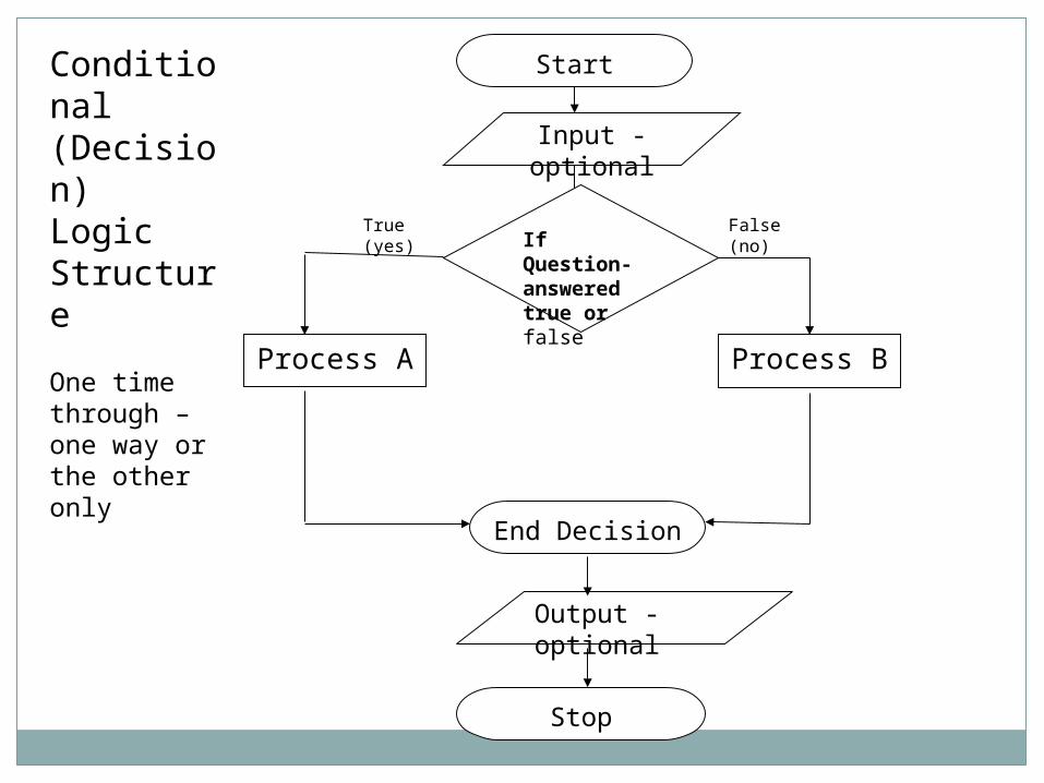
Start
Input -optional
Process A
Output -optional
Process B
Stop
If Question- answered true or false
True (yes) False (no)
Conditional (Decision)Logic Structure
One time through – one way or the other only
End Decision
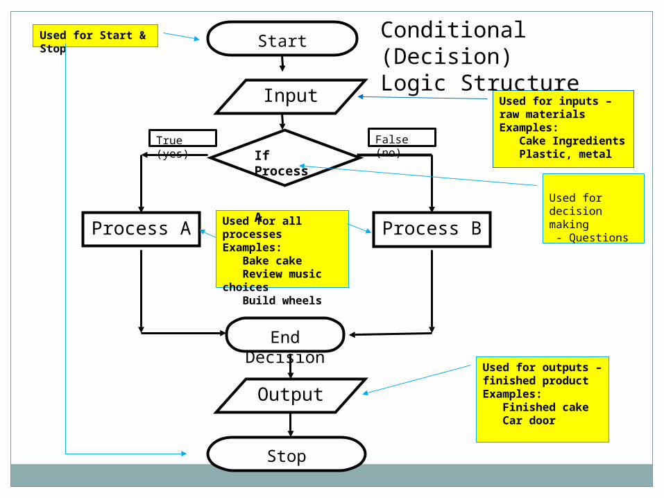
Start
Input
Process A
Output
Process B
Stop
Used for Start & Stop
Used for inputs – raw materials Examples: Cake Ingredients Plastic, metal
Used for outputs – finished product Examples: Finished cake Car door
Used for all processes Examples: Bake cake Review music choices Build wheels
If Process A
True (yes)
False (no)
Used for decision making - Questions
Conditional (Decision)Logic Structure
End Decision
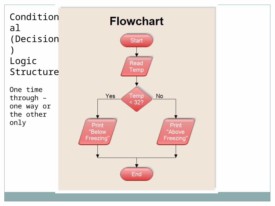
Conditional (Decision)Logic Structure
One time through – one way or the other only
End Decision
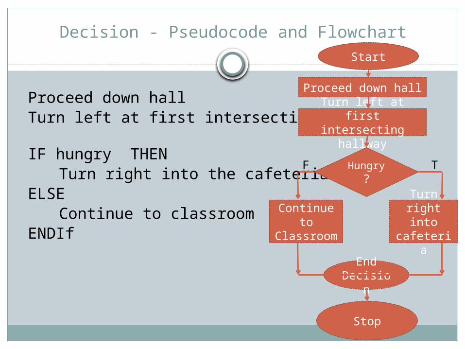
Decision - Pseudocode and Flowchart
Proceed down hallTurn left at first intersecting hallway
IF hungry THENTurn right into the cafeteria
ELSEContinue to classroom
ENDIf
Stop
Proceed down hall
Turn left at first intersecting
hallway
Hungry?
Turn right into cafeteria
Start
Continue to
Classroom
TF
Iteration Control Structure
Represents the computer’s ability to repeat a series of instructions
Loop – a series of repeated instructions
Infinite loop – instructions that would continue without a way out.
Every loop must include a statement that defines how many times to execute the loop steps or under what condition to continue or stop the looping process.
Iteration Control Structure
DOWHILE hair is not cleanWash hairRinse hair
ENDDO
End Decisio
n
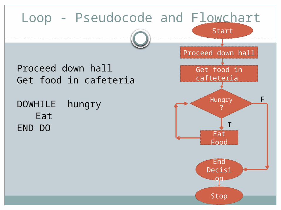
Loop - Pseudocode and Flowchart
Proceed down hallGet food in cafeteria
DOWHILE hungry Eat
END DO
Stop
Proceed down hall
Get food in cafteteria
Hungry?
Eat Food
Start
F
T
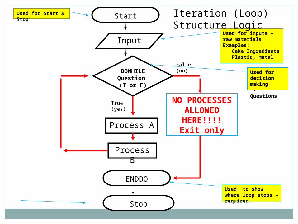
Start
Input
Process A
NO PROCESSES ALLOWED
HERE!!!!Exit only
Stop
Used for Start & Stop
Used for inputs – raw materials Examples: Cake Ingredients Plastic, metal
Used to show where loop stops – required.
DOWHILE Question (T or F)
True (yes)
False (no)
Process B
Used for decision making - Questions
ENDDO
Iteration (Loop) Structure Logic
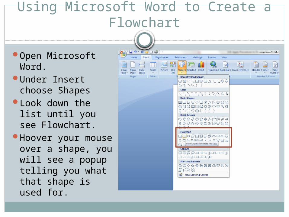
Using Microsoft Word to Create a Flowchart
Open Microsoft Word.
Under Insert choose Shapes
Look down the list until you see Flowchart.
Hoover your mouse over a shape, you will see a popup telling you what that shape is used for.
Using Microsoft Word to Create a Flowchart
Select and draw the shapes needed for your program logic.
Once you draw a shape you can right click and select Add Text to enter information into your symbol.
Join your symbols using arrows indicating program data flow.
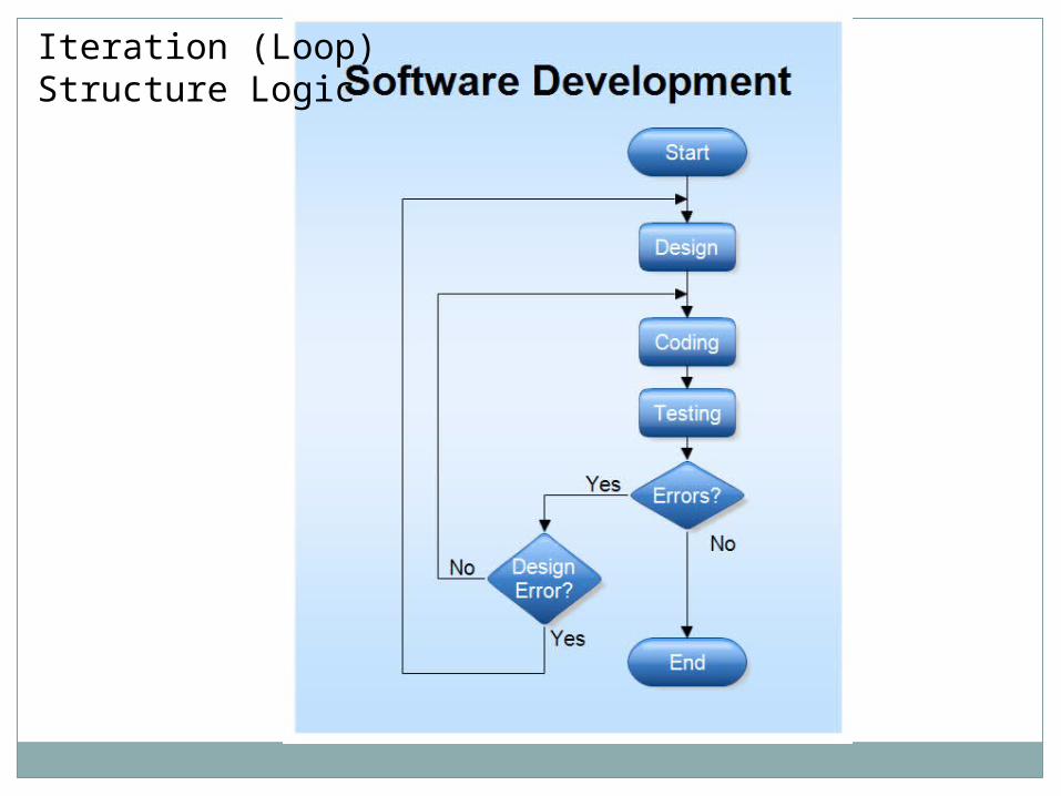
Iteration (Loop) Structure Logic
Expectations
Some general rules: If you do not understand the problem, you probably
will not be able to create a solution. Remember to start with the solution in mind. Your program solution should not necessarily look like
that of another programmer. Use your tools to help you determine your solution.