Embed Size (px)
Citation preview
This report was prepared for the U.S. Department of Energy by the Engineering Department of the Management and Operating Contractor, Waste Isolation Pilot Plant, under Contract DE-ACW86AL3 1950
CONCEPTUAL DESIGN FOR OPERATIONAL PHASE
PANELCLOSURESYSTEMS
Any comments or questions regarding this- report should be directed to the U.S. Department of Energy
WIPP Project Office P. 0. Box 3090
Carlsbad, New Mexico 88221
or to the
Manager Engineering Department Westinghouse Electric Corporation
Waste Isolation Division P.O. Box 2078
Carlsbad, New Mexico 88221
J
4 Acknowledgments Id
\ Mr. John B. Case of IT Corporation provided the technical direction for this report. He was assisted by Dr. Jonathan Myers of IT Corporation, who provided regulatory guidance,
&! evaluation of the gas generation rates, and analysis of VOC mass flow rates.
a Mr. Craig Givens of IT Corporation prepared the literature review section on panel barriers and evaluated previous designs. Mr. Brett Stenson of RE/SPEC prepared the section on
R disturbed rock zone characterization and assisted in selecting disturbed rock zone properties.
u Dr. Saeid Saeb provided a review of the disturbed rock zone properties and peer review of the report.
Mr. A. E. (Bob) Roland of Westinghouse Electric Corporation (Westinghouse) provided an important interface to the Westinghouse staff in developing a conceptual design for the panel closure system. Mr. J. R. Stroble provided an important interface in developing regulatory compliance criteria. Mr. Christopher Francke of Westinghouse provided room convergence information on Panel 1 closure rates for the gas generation model. Mr. Srikanth Mangalam of IT Corporation provided several important calculations on VOC mass flow rates. Mr. Miguel Valdivia assisted in performing the literature search and in preparing Appendix A.
4 Certification d
a, I certify under penalty of law that this document was prepared under my supervision for I Westinghouse Electric Corporation, Waste Isolation Division, Waste Isolation Pilot Plant, by
Id IT Corporation according to the IT Environmental Engineering and Services Quality Assurance Program. This program is designed to assure that qualified personnel properly
M gather and evaluate the information submitted. Based on my inquiry of the persons directly . responsible for gathering the information, the information submitted is, to the best of my knowledge and belief, true, accurate, and complete.
pk~ bfd John B. Case, P. New Mexico Certification No. 8049 Expires December 3 1; 1995
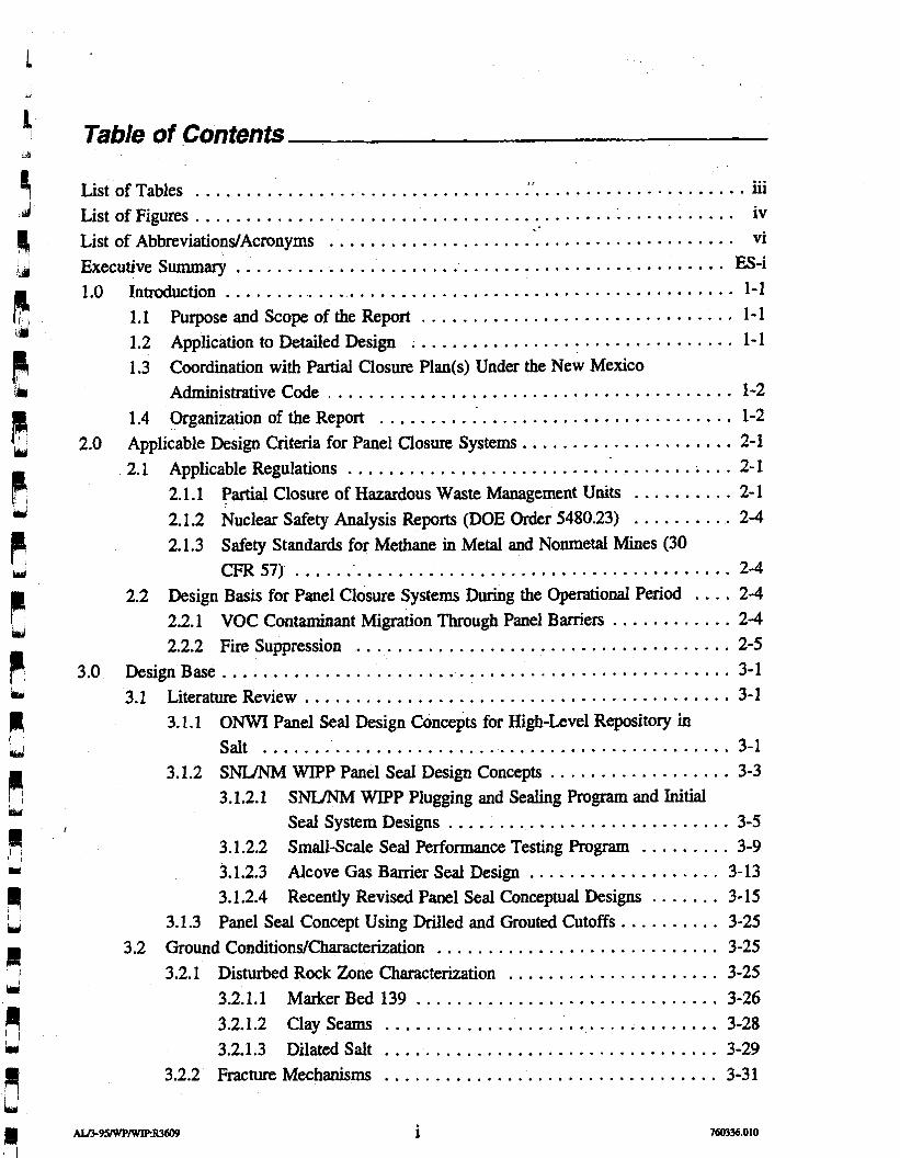
Table of Contents
I I . . . . . . . . . . . . . . . . . . . . . . . . . . . . . . . . . . . . . . . . . . . . . . . . . . . . . . List of Tables iii . . . . . . . . . . . . . . . . . . . . . . . . . . . . . . . . . . . . . . . . . . . . . . . . . . . . . ListofFigures iv
. . . . . . . . . . . . . . . . . . . . . . . . . . . . . . . . . . . . . . . . List of Abbreviations/Acronyms vi . . . . . . . . . . . . . . . . . . . . . . . . . . . . . . . . . . . . . . . . . . . . . . . . Executive Summary ES-i
. . . . . . . . . . . . . . . . . . . . . . . . . . . . . . . . . . . . . . . . . . . . . . . . . . 1.0 Introduction 1-1 . . . . . . . . . . . . . . . . . . . . . . . . . . . . . . . 1.1 Purpose and Scope of the Report 1-1
. . . . . . . . . . . . . . . . . . . . . . . . . . . . . . . . 1.2 Application to Detailed Design 1-1 1.3 Coordination with Partial Closure Plan(s) Under the New Mexico
. . . . . . . . . . . . . . . . . . . . . . . . . . . . . . . . . . . . . . . . Administrative Code 1-2 . . . . . . . . . . . . . . . . . . . . . . . . . . . . . . . . . . . 1.4 Organization of the Report 1-2
. . . . . . . . . . . . . . . . . . . . . 2.0 Applicable Design Criteria for Panel Closure Systems 2-1 . . . . . . . . . . . . . . . . . . . . . . . . . . . . . . . . . . . . . . 2.1 Applicable Regulations 2-1
. . . . . . . . . . 2.1.1 Partial Closure of Hazardous Waste Management Units 2-1 2.1.2 Nuclear Safety Analysis Reports (DOE Order 5480.23) . . . . . . . . . . 2-4 2.1.3 Safety Standards for Methane in Metal and Nonmetal Mines (30
CFR57) . . . . . . . . . . . . . . . . . . . . . . . . . . . . . . . . . . . . . . . . . . . 2-4 .... 2.2 Design Basis for Panel Closure Systems During the Operational Period 2-4
2.2.1 VOC Contaminant Migration Through Panel Barriers . . . . . . . . . . . . 2-4 . . . . . . . . . . . . . . . . . . . . . . . . . . . . . . . . . . . . . 2.2.2 Fire Suppression 2-5
. . . . . . . . . . . . . . . . . . . . . . . . . . . . . . . . . . . . . . . . . . . . . . . . . . 3.0 DesignBase 3-1 . . . . . . . . . . . . . . . . . . . . . . . . . . . . . . . . . . . . . . . . . . 3.1 Literature Review 3-1
3.1.1 ONWI Panel Seal Design Concepts for High-Level Repository in Salt . . . . . . . . . . . . . . . . . . . . . . . . . . . . . . . . . . . . . . . . . . . . . . 3-1
3.1.2 SNUNM WIPP Panel Seal Design Concepts . . . . . . . . . . . . . . . . . . 3-3 3.1.2.1 SNUNM WIPP Plugging and Sealing Program and Initial
. . . . . . . . . . . . . . . . . . . . . . . . . . . . I Seal System Designs 3-5 3.1.2.2 Small-Scale Seal Performance Testing Program . . . . . . . . . 3-9 3.1.2.3 Alcove Gas Barrier Seal Design . . . . . . . . . . . . . . . . . . . 3-13 3.1.2.4 Recently Revised Panel Seal Conceptual Designs . . . . . . . 3-15
3.1.3 Panel Seal Concept Using Drilled and Grouted Cutoffs . . . . . . . . . . 3-25 . . . . . . . . . . . . . . . . . . . . . . . . . . . . 3.2 Ground Conditions/Cbaracterization 3-25
. . . . . . . . . . . . . . . . . . . . . 3.2.1 Disturbed Rock Zone Characterization 3-25 3.2.1.1 Marker Bed 139 . . . . . . . . . . . . . . . . . . . . . . . . . . . . . . 3-26
. . . . . . . . . . . . . . . . . . . . . . . . . . . . . . . . . 3.2.1.2 Clay Seams 3-28
. . . . . . . . . . . . . . . . . . . . . . . . . . . . . . . . . 3.2.1.3 Dilated Salt 3-29
. . . . . . . . . . . . . . . . . . . . . . . . . . . . . . . . . 3.2.2 Fracture Mechanisms 3-31
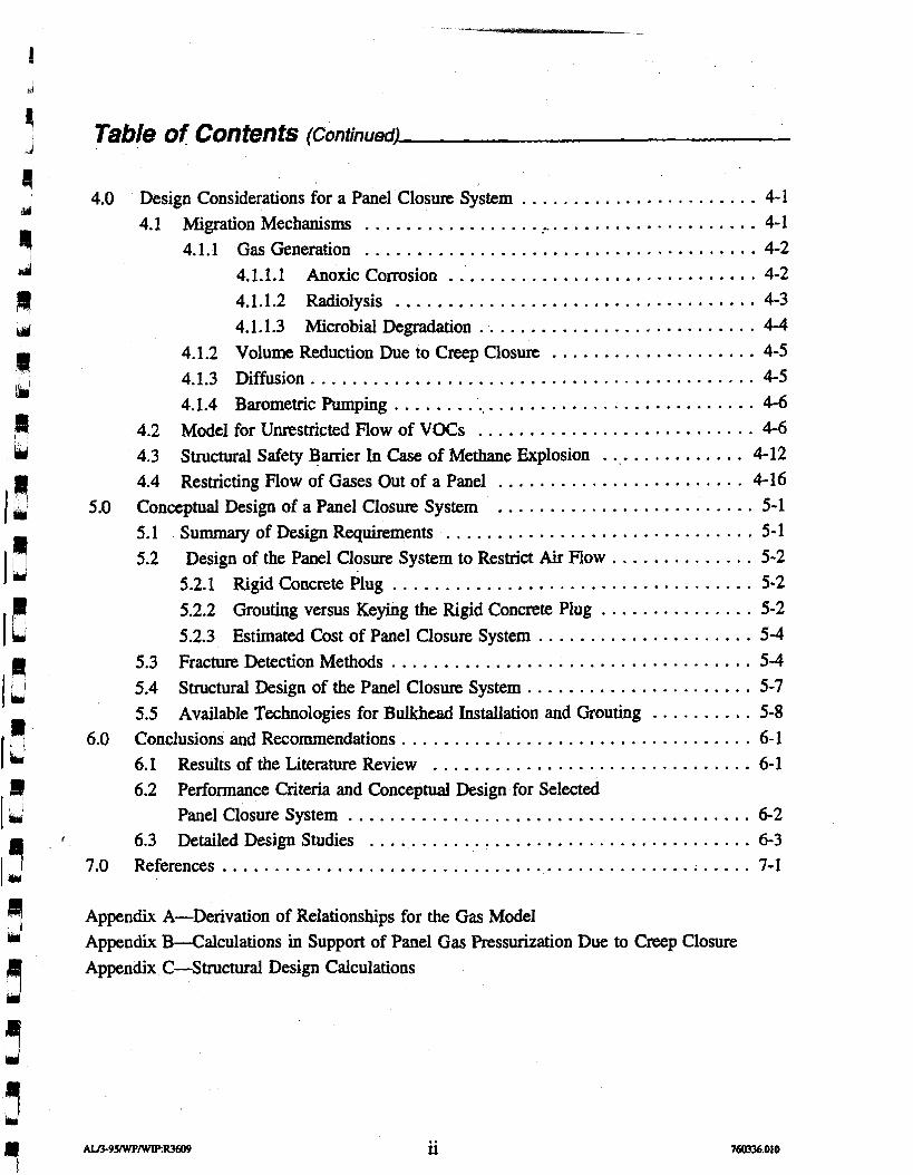
Table of Contents (Continued)
4.0 Design Considerations for a Panel Closure System . . . . . . . . . . . . . . . . . . . . . . . 4-1 . . . . . . . . . . . . . . . . . . . . . . . . . . . . . . . . . . . . . 4.1 Migration Mechanisms ,. 4-1 . . . . . . . . . . . . . . . . . . . . . . . . . . . . . . . . . . . . . . 4.1.1 Gas Generation 4-2
. . . . . . . . . . . . . . . . . . . . . . . . . . . . . . 4.1.1.1 Anoxic Corrosion 4-2 4.1.1.2 Radiolysis . . . . . . . . . . . . . . . . . . . . . . . . . . . . . . . . . . . 4-3 4.1.1.3 Microbial Degradation . . . . . . . . . . . . . . . . . . . . . . . . . . . 4-4
4.1.2 Volume Reduction Due to Creep Closure . . . . . . . . . . . . . . . . . . . . 4-5 . . . . . . . . . . . . . . . . . . . . . . . . . . . . . . . . . . . . . . . . . . . 4.1.3 Diffusion 4-5
. . . . . . . . . . . . . . . . . . . . . . . . . . . . . . . . . . . 4.1.4 Barometric Pumping 4-6 . . . . . . . . . . . . . . . . . . . . . . . . . . . 4.2 Model for Unrestricted Flow of VOCs 4-6
............... 4.3 Structural Safety Barrier In Case of Methane Explosion 4-12 . . . . . . . . . . . . . . . . . . . . . . . . 4.4 Restricting Flow of Gases Out of a Panel 4-16 . . . . . . . . . . . . . . . . . . . . . . . . . 5.0 Conceptual Design of a Panel Closure System 5-1
. . . . . . . . . . . . . . . . . . . . . . . . . . . . . . 5.1 Summary of Design Requirements 5-1 5.2 Design of the Panel Closure System to Restrict Air Flow . . . . . . . . . . . . . . 5-2
. . . . . . . . . . . . . . . . . . . . . . . . . . . . . . . . . . . 5.2.1 Rigid Concrete Plug 5-2 . . . . . . . . . . . . . . . 5.2.2 Grouting versus Keying the Rigid Concrete Plug 5-2
5.2.3 Estimated Cost of Panel Closure System . . . . . . . . . . . . . . . . . . . . . 5-4 5.3 Fracture Detection Methods . . . . . . . . . . . . . . . . . . . . . . . . . . . . . . . . . . . 5-4 5.4 Structural Design of the Panel Closure System . . . . . . . . . . . . . . . . . . . . . . 5-7 5.5 Available Technologies for Bulkhead Installation and Grouting . . . . . . . . . . 5-8
6.0 Conclusions and Recommendations . . . . . . . . . . . . . . . . . . . . . . . . . . . . . . . . . . 6-1 6.1 Results of the Literature Review . . . . . . . . . . . . . . . . . . . . . . . . . . . . . . . 6-1 6.2 Performance Criteria and Conceptual Design for Selected
. . . . . . . . . . . . . . . . . . . . . . . . . . . . . . . . . . . . . . . Panel Closure System 6-2 f . . . . . . . . . . . . . . . . . . . . . . . . . . . . . . . . . . . . . 6.3 Detailed Design Studies 6-3
7.0 References . . . . . . . . . . . . . . . . . . . . . . . . . . . . . . . . . . . . . . . . . . . . . . . . . . . 7-1
Appendix A-Derivation of Relationships for the Gas Model Appendix B.-C alculations in Support of Panel Gas Pressurization Due to Creep Closure Appendix C.4 tructural Design Calculations
List of Tables dd
Title
2- 1 Land-Disposal Restricted VOCs in the WIPP Inventory and their Health-Based Levels for Air
3- 1 Small-Scale Seal Performance Test Series Description
4- 1 Gas Generation Rates in a Humid Environment
4 4-2 Closed Panel Release Limits for VOCs
R 4-3 Closed Panel Release Rates for VOCs d
1"1 Er'
iii
List of Figures
Figure Title
3- 1 Basic Components for Shaft and Tunnel Seals in Bedded Salt Repository
3-2 Concept for Concrete Tunnel Bulkheads-Bedded Salt Repository
3-3 Cross-Sectional View of Panel Seals
3-4 Drift and Panel Seal Plan, Elevation and Section
3-5 Small-Scale Seal Performance Test (SSSPT) Generalized Test Configurations
3-6 Alcove Gas Barrier in the WIPP Underground Storage Horizon Stratigraphy
3-7 Alcove Gas Barrier Construction Elements
3-8 Cast-in-Place Concrete Portals for Alcove Gas Barrier
Types of Seals with Base Case and Alternative Case
NOW Concepts for Operational Period Barrier .
LATER Concepts for Operational Period Barrier
Classification of Discontinuity Features
Spatial Correlation of Discontinuity Features
Schedule for Panel Completion
Potential Explosive Mixtures of Methane
Methane Concentrations in the Waste Panel Over Time
Pressure Buildup with Time for a Single Panel
Mass Flow Rate for Carbon Tetrachloride with Time for a Single Panel
Closed Panel Release Rate versus Limit Comparison for Carbon Tetrachloride and Other VOCs
4-7 Closed Panel Release Rate versus Limit Comparison for Other VOCs
ALTr95IWPtWRR3609 iv 760336.01 0
List of Figures (Continued)
Figure Title
5- 1 Conceptual Design of a Panel Closure System
5-2 Rigid Barrier Contact Grouting
5-3 Construction of the Rigid Concrete Plug
5-4 Typical Equipment Layout for a Grouting Operation
5-5 Multiple Packer Sleeved Pipe in Place (Left), Single Zone Being Grouted (Right)
List of Abbreviations/Acronyms
AGB ALARA atm cfm CFR cm DOE DOL DRZ EEP EP A ft
GPR gr HEPA HWMU INEL kg ksi m MI3 139 MHz MOU MPa mrem MSHA NMAC NMED Pg ns o m ODE psi RCRA SNL/NM SPDV SSSPT TRU VOC(s) WID WIPP
alcove gas barrier as low as reasonably achievable atmospheric pressure cubic feet per minute Code of Federal Regulations centimeter(s) U.S. Department of Energy U.S. Department of Labor dsturbed rock zone Excavation Effects Program U.S. Environmental Protection Agency foot (feet) gram(s> ground penetrating radar gas-generation rate high-efficiency particulate air hazardous waste management unit(s) Idaho National Engineering Laboratory kilogram(s) kip(s) per square inch meter(s) Marker Bed 139 megahertz memorandum of understanding megapascal(s) milliroentgen(s) Mine Safety and Health Administration New Mexico Administrative Code New Mexico Environment Department microgram(s) nanosecond(s) Office of Nuclear Waste Isolation ordinary differential equation pound(s) per square inch Resource Conservation and Recovery Act Sandia National LaboratoriesMew Mexico Site and Preliminary Design Validation small-scale seal performance tests transuranic volahle organic cornpound(s) Waste Isolation Division Waste Lsolation Pilot Plant
8, I Executive Summary LA4
P The Waste Isolation Pilot Plant (WIPP), a U.S. Department of Energy (DOE) research facility
d located near Carlsbad, New Mexico, was established to demonstrate the safe disposal of defense-generated transuranic (TRU) waste. The WIPP repository is approximately 2,150 feet
F1 (ft) (655 meters [m]) below the surface in bedded salt. The WIPP facility includes a northern
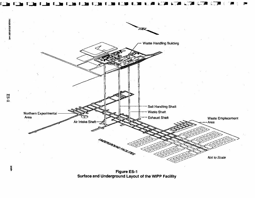
u& experimental area, a shaft pillar area, and a waste disposal area. The waste disposal area is comprised of panels, each of which consists of seven rooms and two access panel entries (Figure ES-1).
Following completion of waste emplacement in each panel, ventilation will be established in the next panel to be used, and the panel containing the waste will be closed. The DOE wiU seek New Mexico Environment Department (NMED) approval for "partial closure" of each of the panels as they are sequentially filled with waste on a panel-by-panel basis. Partial closure is the process of rendering a part of the underground repository inactive and closed according to the approved facility closure plan.
The plan covers administrative procedures deemed necessary by the U.S. Environmental Protection Agency (EPA) to provide assurance that individual panel closures are being achieved according to the New Mexico Administrative Code (NMAC) Resource Conservation and Recovery Act (RCRA) permit and as a condition of this permit. The partial closure plan will address requirements for future monitoring that are deemed necessary for the postclosure period.
A review of existing literature on panel closure systems, including the applicable design criteria for closure systems during the anticipated operational life of the facility of 35 years, was conducted. The literature review included panel barrier concepts and field testing as developed by the Office of Nuclear Waste Isolation (ONWI) high-level waste program, the Sandia National LaboratoriesNew Mexico (SNLMM) WIPP repository sealing program, and other panel barrier concepts. This information was reviewed because of its application to demonstrating compliance to health-based levels of Land Disposal Restricted volatile organic compounds (VOC) during underground operations. The results of the literature review are presented to summarize previous panel barrier designs and their application to WKPP. In addition, information is presented on the disturbed rock zone (DRZ) (i.e., information on its extent and permeability enhancement), on potential fracturing of the anhydrite MB 139, and on interface zone properties directly relevant to developing a conceptual design for panel closure systems.
This report considers engineering designs such that the closure system for closed panels other than the active emplacement panel(s) will prevent migration of constituents in concentrations above health-based levels beyond the WIPP land withdrawal boundary. The analysis considers plans for sequencing of waste emplacement operations for the individual closures for ten equivalent panels during-the 35 year operational/closure period. Two models were prepared to evaluate the flow rate of VOCs out of the closed panels. One model evaluated unrestricted flow. Another model evaluated restricted flow through a barrier system. The analysis shows that for the expected gas generation rate of 8,200 moles per panel per year
Waste Handling Building
Salt Handling Shaft
Not to Scale
Figure ES-1 Surface and Underground Layout of the WlPP Facility
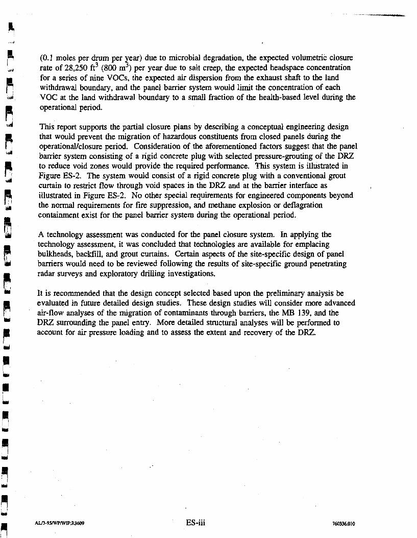
(0.1 moles per drum per ear) due to microbial degradation, the expected volumetric closure K rate of 28,250 fi3 (800 m ) per year due to salt creep, the expected headspace concentration for a series of nine VOCs, the expected air dispersion from the exhaust shaft to the land withdrawal boundary, and the panel barrier system would limit the concentration of each VOC at the land withdrawal boundary to a small fraction of the health-based level during the operational period.
This report supports the partial closure plans by describing a conceptual engineering design that would prevent the migration of hazardous constituents from closed panels during the operationaVclosure period. Consideration of the aforementioned factors suggest that the panel barrier system consisting of a rigid concrete plug with selected pressure-grouting of the DRZ to reduce void zones would provide the required performance. This system is illustrated in Figure ES-2. The system would consist of a rigid concrete plug with a conventional grout curtain to restrict flow through void spaces in the DRZ and at the barrier interface as illustrated in Figure ES-2. No other special requirements for engineered components beyond the normal requirements for fire suppression, and methane explosion or deflagration containment exist for the panel barrier system during the operational period.
A technology assessment was conducted for the panel closure system. In applying the technology assessment, it was concluded that technologies are available for emplacing bulkheads, backfill, and grout curtains. Certain aspects of the site-specific design of panel barriers would need to be reviewed following the results of site-specific ground penetrating radar surveys and exploratory drilling investigations.
It is recommended that the design concept selected based upon the preliminary analysis be evaluated in future detailed design studies. These design studies will consider more advanced air-flow analyses of the migration of contaminants through barriers, the MB 139, and the DRZ surrounding the panel entry. More detailed structural analyses will be performed to account for air pressure loading and to assess the extent and recovery of the DRZ.
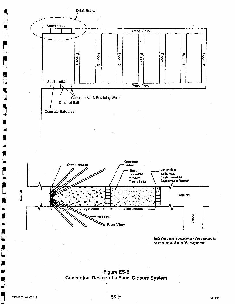
?tail Below
I - Concrete Bulkhead Concrete Blodc Wall to Assist Sunplo Crushed Salt
Thermal B a n k Emplacqml as Required
- Grout Pioes
Note that design mponents will be seleded for radiation protection and fire sgpbssion.
Figure ES-2 Conceptual Design of a Panel Closure System
1.7 Purpose and Scope of the Report The Waste Isolation Pilot Plant (WPP), a U.S. Department of Energy (DOE) research facility
located near Carlsbad, New Mexico, was established to demonstrate the safe disposal of
defense-generated transuranic (TRU) waste. The WIPP repository is approximately 2,150 feet
(ft) (655 meters [m]) below the surface in the Salado Formation. The WIPP facility consists
of a northern experimental area, a shaft-pillar area, and a waste disposal area.
One important aspect of future repository operations is the activities associated with closure
of waste-storage panels. Each panel consists of seven rooms and two access panel entries.
After completion of waste-emplacement activities in these entries, the fully emplaced panel
will be closed while waste is being emplaced in the active operational panel(s). The closure
of individual panels during the operational period will be conducted for compliance with
health, safety, and environmental protection performance criteria established for the project.
This report provides information on existing literature regarding panel closure systems relative
to the operational period of the WlPP and presents a conceptual design for panel closure
systems. The literature review includes the applicable design criteria for closure systems
during the anticipated operational life of 35 years. Because one method of achieving panel
closure is constructing barriers, this report reviews sealing or bamer concepts developed as
part of long-term waste isolation for the Office of Nuclear Waste Isolation (ONWI)
Repository Sealing Project and the current concepts developed for the Sandia National
LaboratoriesLNew Mexico (SNWNM) WIPP Repository Sealing Project. Because flow
through the panel closure system could occur through the disturbed rock zone (DRZ) surrounding the panel entries, this report presents information on this zone.
To receive a no-migration variance, WIPP must determine that there will be no migration of
hazardous constituents in concentrations above health-based levels beyond the land
withdrawal boundary. Until final closure (shaft seal certif~cation), the panel closure system
will act as an engineered barrier for limiting releases of hazardous constituents.
1.2 Application to Detailed. Design The conceptual design selected in this report, based upon the preliminary analysis contained
herein, will be evaluated in future detailed design studies. For panel barriers, these design
studies will consider more advanced analyses of the migration of contaminants through
barriers, clay seams, the anhydrite marker bed (MB 139), and the DRZ surrounding the panel
entries, as well as methods for treatment of the DRZ. More detailed structural analyses will
be performed to account for air-pressure loading and to assess the extent and recovery of the
DRZ.
1.3 Coordination with Partial Closure Plan@) Under the New Mexico Administrative Code
The state of New Mexico, through the New Mexico Administrative Code (NMAC), Title 20,
Section 4.1, implements the requirements of the Resource Conservation and Recovery Act
(RCRA). The closure of individual panels will be according to 20 NMAC 4.1, Subpart V,
which governs the management and operation of hazardous waste systems. The regulations
require preparation and approval of individual RCRA partial closure plans that identify the
steps necessary to perform partial closure. The partial closure plans will present a description
of closure activities, an estimate of the inventory of hazardous wastes within each panel, and
a schedule for closure and certification of closure. The plan will also cover administrative
procedures deemed necessary by the New Mexico Environment Department (NMED) to
provide assurance that individual panel closures are being achieved according to the
conditions of the hazardous waste permit.
This report supports the partial closure plans by describing the components and activities that,
through engineering design, would provide a "structurally" stable system that would limit
leakage of hazardous constituents.
1.4 Organization of the Report Chapter 2.0 presents a literature review of the applicable design criteria to panel closure
systems. Chapter 3.0 presents a literature review of previous design concepts applied to drift
and panel-closure systems from previous design studies in salt. Chapter 4.0 presents design
considerations for passive panel-closure systems. This includes migration mechanisms, the
source of VOCs, VOC migration limits, and the structural safety banier for the panel banier
system. Also, it includes a gas-flow model for restricting VOCs during the WIPP operational
period. Chapter 5.0 presents detailed description of the conceptual design. It also presents a
brief discussion on available technologies for construction of the panel closure systems.
Chapter 6.0 presents conclusions and recommendations for future design work.
2.0 Applicable Design Criteria for Panel Closure Systems
This chapter summarizes the regulations that apply to the engineering design of panel closure
systems that may affect the design of these systems. This information is presented in the
Underground Hazardous Waste Management Unit Closure Criteria for the Waste Isolation
Pilot Plant Operational Period (Westinghouse, 1995).
2.1 Applicable Regulations Applicable regulations include the requirements for partial closure of hazardous waste
management units under RCRA (Title 40, Code of Federal Regulations [CFR], Part 264
[40 CFR 264]), Part 268 [40 CFR 2681, and the NMED implementing regulations (20 NMAC '
4.1, Subpart V), various DOE orders, and radiation exposure to as low as reasonably
achievable (ALARA) limits. Also, they include mine health and safety regulations for metal
and nonmetal mines.
2.1.1 Partial Closure of Hazardous Waste Management Units Waste containers will be emplaced in eight panels and panel accessways. The panel
accessways are equivalent in capacity to two panels. Each panel equivalent will hold a
volume equivalent to approximately 81,000 drums of waste. The DOE will seek approval for
"partial closure" of each of the eight individual panels as they are sequentially filled with
waste on a panel-by-panel basis. Partial closure is the process of rendering a part of the
underground repository inactive and closed according to the approved facility closure plans.
The requirements of 20 NMAC 4.1, Subpart V, $264.103@) state that:
"The owner or operator must complete partial and final closure activities in accordance with the approved closure plan and within I80 days afer receiving the final volume of hazardous wastes, or the final volume of non-hazardous waste. . . ."
Partial closure will be considered complete when the panel-closure system is emplaced and
operational and when the NMED has approved the closure. Final closure of the facility will
occur when the remaining panels are closed, when the underground facility and related
equipment and structures have been decontaminated (if necessary), and when the shaft seals
have been emplaced.
Subpart X of 40 CFR 264 (EPA, 1994) includes the requirements that are applicable to the
disposal of hazardous waste in miscellaneous units. Because the WIPP underground
management units are categorized as miscellaneous units, the no-migration standards set forth
in 20 NMAC 4.1, Subpart V, §264.601(~)(1) and (2), are applicable:
"Prevention of any release that may have adverse efects on human health or the environment due to the migration of waste constituents in the air, considering:
( I ) the volume and physical and chemical characteristics of the waste in the unit, including its potential for the emission and dispersal of gases, aerosols, and particulates;
(2) the efectiveness and reliability of systems and structures to reduce or prevent emissions of hazardous constituents to the air. . . . "
In accordance with 40 CFR 268.6, the DOE must demonstrate that hazardous constituents will
not migrate beyond the unit boundary in concentrations exceeding health-based levels. The
unit boundary for disposal operations and the closure period will be the 16-section land
withdrawal boundary. During the operational period, the only credible pathway for the
migration of hazardous constituents from the disposal unit is by airborne transport of VOCs
(DOE, 1990). For the land-disposal restricted hazardous VOC constituents in the WIPP
inventory, "migration" is the movement of the constituent across the land withdrawal
boundary at concentrations above the health-based levels in air for that constituent. The list
of land-disposal restricted VOC constituents in the WIPP inventory that make up 99 percent
of the health-based risk, and their health-based levels is shown in Table 2-1.
The closure-system design will consider the volumetric reduction of the closed area due to
creep closure, expected pressures resulting from gas generation, differential pressures across
the closure system induced by the repository ventilation system, and diffusion of VOCs
through the closure system (Westinghouse, 1995). Closure performance standards, as cited
from 20 NMAC 4.1, Subpart V, $264.11 1, require that:
"The owner or operator shall close the facility in a manner that:
(a) Minimizes the need for further maintenance; and
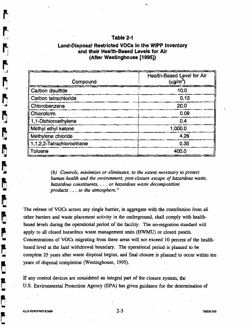
Table 2-1 Land-Disposal Restricted VOCs in the WlPP Inventory
and their Health-Based Levels for Air (After Westinghouse [I 9951)
(b) Controls, minimizes or eliminates, to the extent necessary to protect human health and the environment, post-closure escape of hazardous waste, hazardous constituents, . . . or hazardous waste decomposition products . . . to the atmosphere."
Compound
Carbon disulfide
Carbon tetrachloride
C hlorobenzene Chloroform 1 ,l -Dichloroethylene Methyl ethyl ketone
Methylene chloride 1 ,I ,2,2-Tetrachloroethane Toluene
The release of VOCs across any single barrier, in aggregate with the contribution from all
other barriers and waste placement activity in the underground, shall comply with health-
based levels during the operational period of the facility. The no-migration standard will
apply to all closed hazardous waste management units (HWMU) or closed panels.
Concentrations of VOCs migrating from these areas will not exceed 10 percent of the health-
based level at the land withdrawal boundary. The operational period is planned to be
complete 25 years after waste disposal begins, and final closure is planned to occur within ten
years of disposal completion (Westinghouse, 1995).
Health-Based Level for Air (%dm3)
10.0
0.13
20.0 0.09
0.4 1,000.0
4.26 0.35
400.0
If any control devices are considered an integral part of the closure system, the
U.S. Environmental Protection Agency P A ) has given guidance for the determination of
adequacy of such control devices in their Land Disposal Restrictions "No-Migration"
Variances, Proposed Rule, Federal Register, Tuesday, August 11, 1992 (57FR35940), as:
"To document that a control device achieves this performance level, the owner or operator would be required to use either detailed design specifications for the control device or results of control device perfonnance testing."
2.1.2 Nuclear Safety Analysis Reports (DOE Order 5480.23) DOE Order 5480.23 established uniform requirements for the preparation and review of safety
analyses of operations, including hazards identification, risk assessment, and operations
documentation. The order requires that a closure system safety analysis must be included in , the WIPP Safety Analysis Report.
2.1.3 Safety Standards for Methane in Metal and Nonmetal Mines (30 CFR 57) The WIPP facility is considered a nonmetal mine and complies with parts of 30 CFR specified in the memorandum of understanding (MOU) with the U.S. Department of Labor
(DOL) and DOE. These regulations include the hazards of methane gas and dust containing
volatile matter. There are no implications for the closure system above and beyond standard
WIPP operating practices.
For "seals and stoppings," the regulations provide for the use of noncombustible materials
(where appropriate) for the specific mine category and that seals and stoppings be of
substantial construction. Substantial construction is construction of such strength, material,
and workmanship that the seal or stoppings could withstand air blasts, methane detonation or
deflagration, blasting shock, and ground movement expected in the mining environment.
2.2 Design Basis for Panel Closure Systems During the Operational Period The following sections describe the design basis for panel closure systems during the WIPP operational period.
2.2.1 VOC Contaminant Migration Through Panel Barriers For volatile hazardous waste constituents, the significant design requirement for panel closure
systems will be to restrict the migration mass flow rate of VOCs to the extent that the
no-migration standard (i.e., to meet appropriate health-based levels) are met at the unit
boundary during the operation closure period, which is expected to last 35 years. The
releases from VOCs will not exceed 10 percent of the health-based level concentrations at the
land withdrawal boundary.
2.2.2 Fire Suppression The placement of a barrier and other closure operations must be performed in such a manner
to suppress the potential for fires within the waste emplacement areas.
In conclusion, the requirements for fire suppression are easily satisfied by constructing
noncombustible barriers of substantial construction using current WIPP design practices. The
migration of VOCs may require an engineered panel closure system to comply with
health-based levels, as discussed subsequently in this report.
3.0 Design Base
Much effort has been spent on the conceptualization and design of shaft- and drift-seal
systems and panel-seal or closure systems for the WIPP site and for other candidate
repositories in bedded salt. Most of this work focused on the design of seals to meet
long-term performance standards, specifically the long-term reduction of waste contaminant
migration through brine or gas flow. Design issues related to the short-term operational
period performance at the WIPP have only been recently considered (Van Sambeek et al.,
1993a; Hansen et al., 1993). The discussion below presents a literature review of published
seal and closure system designs in salt to show previous work performed and to present
design components of these existing designs that could be utilized in an operational period I
panel closure system design. Also, a discussion of ground conditions around excavations in
the WIPP underground is included, as well as a discussion of the DRZ and fracture
mechanisms and their effects on panel seal or closure systems.
3.1 Literature Re view The following is a literature review of panel and drift closure system conceptual designs.
Conceptual designs generated for the ONWI program and various historical seal and closure
system designs for the WIPP site are presented.
3.1.1 ONWI Panel Seal Design Concepts for High-Level Repository in Salt The ONWI wrote several reports that describe conceptual designs for penetration seals for
possible National Waste Terminal Storage repository sites in salt (Kelsall et al., 1982; 1983;
1984). Some designs are referenced to the stratigraphy and hydrology of the Permian salt
deposits in southeastern New Mexico (Kelsall et al., 1982).
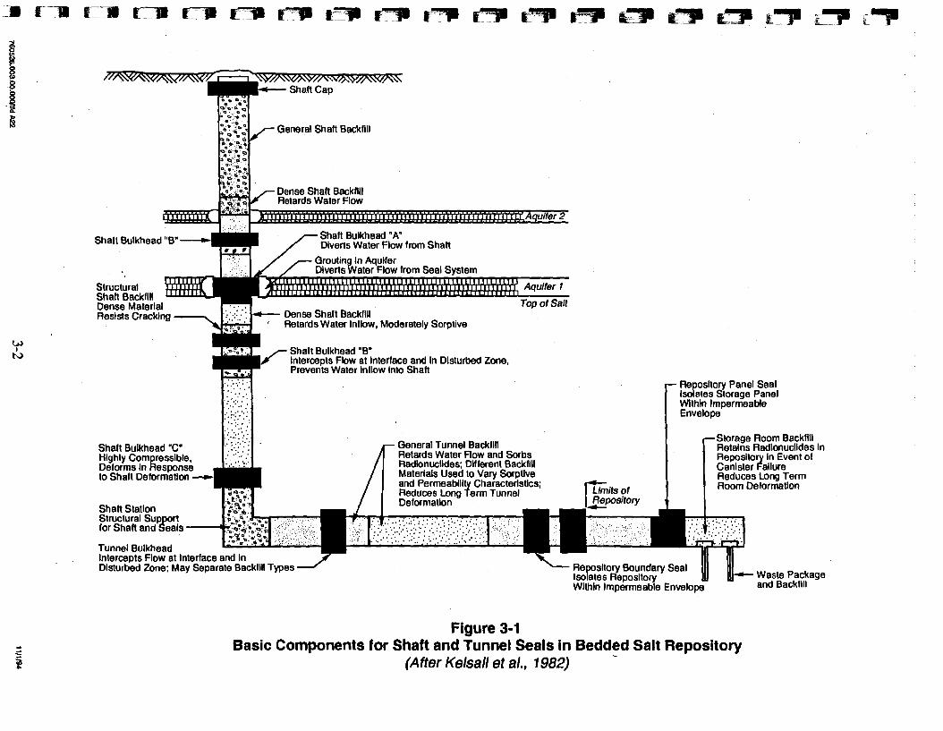
In the proposed shaft and tunnel seal system, two basic types'of seal components were
required, bulkheads and backfill. Figure 3-1 illustrates the use of bulkheads for short-term
performance and backfills for long-term performance as the basic components in the shaft-
and tunnel-seal system. Some bacS1ling components would be placed for radionuclide
retardation, while other components would provide structural support.
The bulkheads were designed to tie low-permeability seal components interspersed with
sections of backfdl in both the shafts and access tunnels. Their primary function is to limit
groundwater flow internally within the seals and through the seal-rock interface and the DRZ.
General Shalt Backfill
Dense Shaft Backllll Retards Water Flow
Shalt Bulkhead "8"- ShaR Bulkhead "A" Diverts Water Flow lrom Shall
7 Qroutina In Aauller I 1 ,/ / Diverts~ater'Flow lrom Seal Svstem
Dense Material
, Moderately Sorptive
Shalt Bulkhead "B" Intercepts Flow at Interlace and In Disturbed Zone, Prevents Water inflow Into Shaft
Repository Panel Seal Isolates Storage Panel Within Impermeable Envelope
. . . . .I.::::: . : ..: ' . . . . -Storage Room Backllll . . . Shalt Bulkhead "C" ...... General Tunnel Backfill Retalns Radionuclides in Retards Water Flow and Sorbs Repository in Event 01
Canister Failure Reduces Long Term Room Delormallon
- Waste Package Within lmpermeable Envelope and Backlill
Figure 3-1 Basic Components for Shaft and Tunnel Seals in Bedded Salt Repository
(After Kelsall et al., 1982)
grout or a bentonite-based slurry was to be used between the bricks and at the roof to ensure
an adequate seal (Stormont, 1984).
A core of bentonite or a bentonite-based mix was located at the center of this initial
multicomponent seal design. The bentonite was to be used because of its low hydraulic
conductivity (from swelling upon contact with water) and its ability to retain certain
radionuclides, making it both a fluid and chemical barrier. This initial drift and panel-access
seal was designed primarily as a water or brine barrier. Gas generation and gas flow through
the seal system had not been seriously considered at the time this seal was designed. Also,
the DRZ was not given full consideration in this initial conceptual seal design.
I
This conceptual design was refined through a combination of office, laboratory, and field
studies. In 1988, Stormont presented the initial seal system design for panel-access drifts
(Stormont, 1988). Crushed salt and salt bricks, bentonite, grouts and concretes, and asphalt
were investigated as possible seal-component materials. In this design, crushed compacted
salt and compacted salt bricks were again to be used as long-term seal components.
Consolidation of the salt by creep closure of the drift would decrease the permeability of the
salt over a period of several hundred years until it would finally reach the permeability of
intact salt (lo-" m2).
Bentonite was again viewed as an integral component of the seal to reduce waterbrine flow
across the seal system during the time that the salt coinponent was consolidating. Pure
bentonite or mixtures of bentonite and crushed salt were considered as candidate materials for
panel-access seals.
Also, grouts and concretes were considered for panel-access seals, as well as for shaft and
borehole seals. Cementitious grout was also considered for grouting fractures in the host rock
(in the DRZ) around the proposed seal location. Fracture grouting had been used in other
underground locations to control inflow to shafts and to establish concrete seals in shafts and
drifts and with dams (Stormont, 1988). However, Stormont also indicated that rock fracture
grouting may be detrimental in some instances. For example, fractures may propagate from
injection pressures during the grouting process. This could increase the permeability and
extent of the DRZ. Stormont recognized that to avoid the propagation of the DRZ due to
grouting, a method of providing a load reaction, such as a stiff bulkhead, was needed.
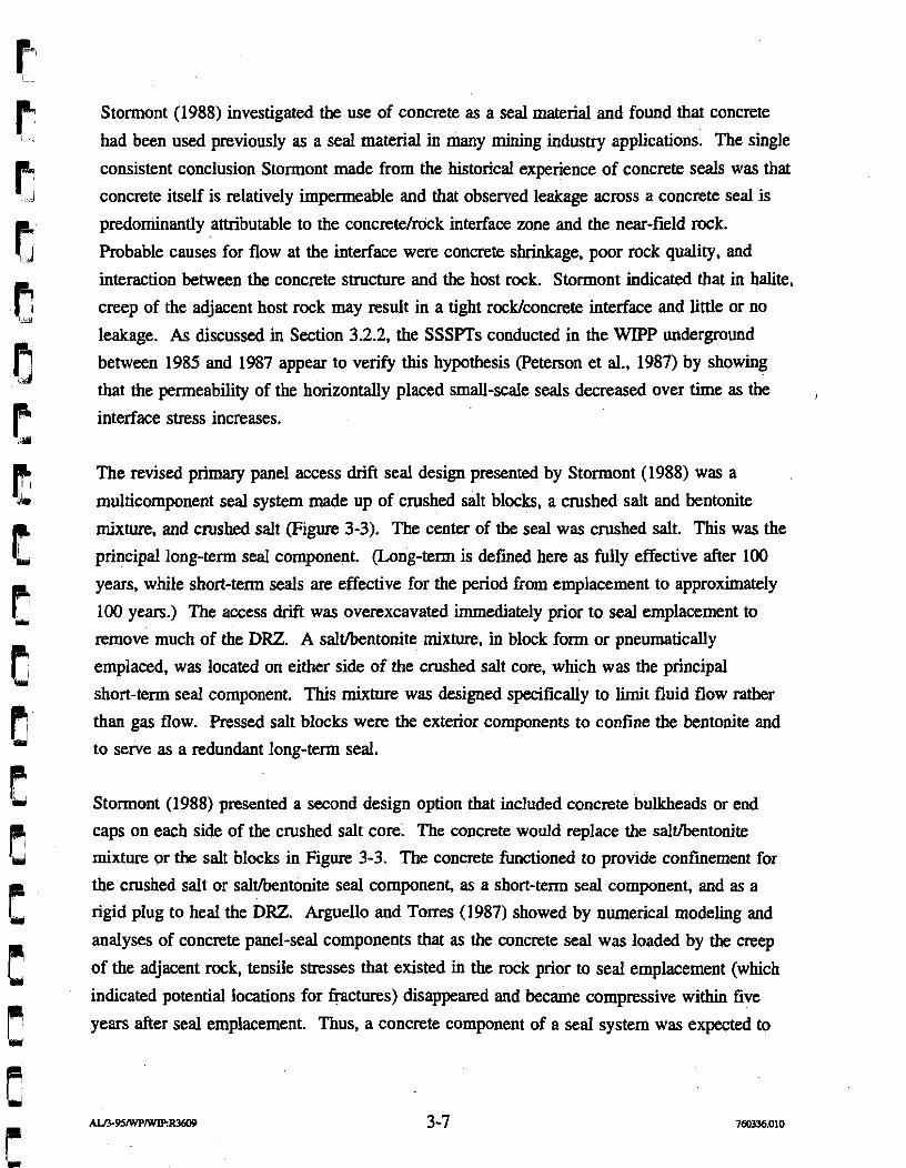
Stormont (1988) investigated the use of concrete as a seal material and found that concrete
had been used previously as a seal material in many mining industry applications. The single
consistent conclusion Stormont made from the historical experience of concrete seals was that
concrete itself is relatively impermeable and that observed leakage across a concrete seal is
predominantly attributable to the concretelrock interface zone and the near-field rock.
Probable causes for flow at the interface were concrete shrinkage, poor rock quality, and
interaction between the concrete structure and the host rock. Stormont indicated that in halite,
creep of the adjacent host rock may result in a tight rocWconcrete interface and little or no
leakage. As discussed in Section 3.2.2, the SSSPTs conducted in the WIPP underground
between 1985 and 1987 appear to verify this hypothesis (Peterson et al., 1987) by showing
that the permeability of the horizontally placed small-scale seals decreased over time as the I
interface stress increases.
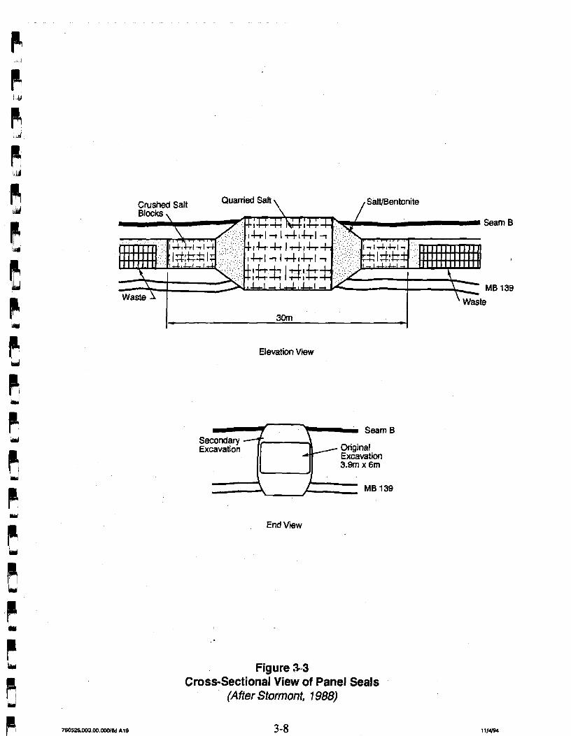
The revised primary panel access drift seal design presented by Stormont (1988) was a
multicomponent seal system made up of crushed salt blocks, a crushed salt and bentonite
mixture, and crushed salt (Figure 3-3). The center of the seal was crushed salt. This was the
principal long-term seal component. (Long-term is defined here as fully effective after 100
years, while short-term seals are effective for the period from emplacement to approximately
100 years.) The access drift was overexcavated immediately prior to seal emplacement to
remove much of the DRZ. A saltlbentonite mixture, in block form or pneumatically
emplaced, was located on either side of the crushed salt core, which was the principal
short-term seal component. This mixture was designed specifically to limit fluid flow rather
than gas flow. h s s e d salt blocks were the exterior components to confine the bentonite and
to serve as a redundant long-term seal.
Stormont (1988) presented a second design option that included concrete bulkheads or end
caps on each side of the crushed salt core. The concrete would replace the salt/bentonite
mixture or the salt blocks in Figure 3-3. The concrete functioned to provide confinement for
the crushed salt or salt/bentonite seal component, as a short-term seal component, and as a
rigid plug to heal the DRZ. Arguello and Tones (1987) showed by numerical modeling and
analyses of concrete panel-seal components that as the concrete seal was loaded by the creep
of the adjacent rock, tensile stresses that existed in the rock prior to seal emplacement (which
indicated potential locations for fractures) disappeared and became compressive within five
years after seal emplacement. Thus, a concrete component of a seal system was expected to
Crushed Salt Quarried Salt \ , SalVBentonite
I- 30m
Elevation Wew
SeamB
Excavation Original Excavation 3.9171 x 6m
End View
Figure 3-3 Cross-Sectional View of Panel Seals
(After Stormont, 1988)
generate a stress field in the adjacent rock that was conducive to healing or tightening of the
salt host rock.
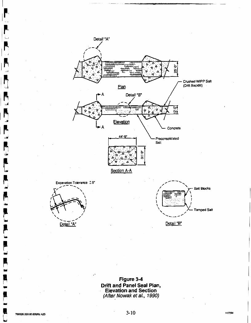
Nowak et al. (1990) presented a further revised panel-access drift seal design primarily based
on Stormont's concrete bulkhead design described above. This conceptual design, presented
in Figure 3-4, consisted of a consolidated crushed salt and crushed salt block core with
concrete bulkheads on each end. Crushed salt was placed with an initial density equal to
80 percent of the density of the intact WlPP salt. That initial state was achieved by pouring
and tamping crushed salt to approximately half the height of the opening and laying
preconsolidated salt blocks to the roof of the opening. Numerical analysis of the
consolidation of the crushed salt seal between concrete bulkheads due to creep closure
predicted that a 95 percent relative density would be reached within 100 years (Arguello,
1988). At 95 percent relative density, the permeability of the consolidated crushed salt was
assumed to be equal to the permeability of the intact, undisturbed salt (Lappin et al., 1989).
3.1.2.2 Smatt-Scate Seal Performance Testing Program The SSSPT consisted of in situ experiments that utilized materials and geometries similar to
the conceptual shaft and panel-seal designs presented by Stormont (1988) and Nowak et al.,
(1990) as discussed in Section 3.1.2.1. The small-scale seals were placed in holes oriented
both vertically into the floor and horizontally into the walls. The primary objectives of the
SSSPT Program (Stonnont, 1985; Finley and Tillerson, 1992) were:
1. To determine in situ fluid flow performance for various seal systems, including evaluating flow paths, the difference between gas and brine permeabilities, and size effects
2. To determine in situ mechanical performance of the host rock and seal materials, including material interfaces and size effects
3. To assess seal-emplacement techniques
4. To support the development of numerical predictive capabilities.
The SSSPT seal system consisted of the seal, seahock interface, and the rock adjacent to the
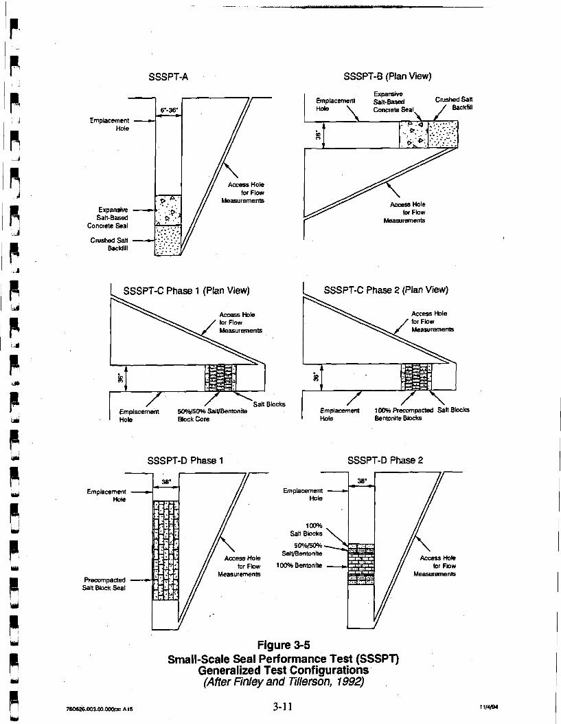
seal (including the DRZ). Table 3-1 summarizes the six series of tests that were performed,
including a description of the primary seal material, orientation, and types of measurements
made. Figure 3-5 shows generalized configurations for each test series. Each seal test
consisted of an emplacement hole drilled either vertically or horizontally and an access hole
Detail 'A"
Plan - Detail 'B' /
Excavation Tolerance 2 6" /--. s/ ' \
\
\ I /
\---- /
Detail 'A'
4 A concrete
Preconsolidated Salt
Section A-A
Salt Blocks
Tamped Salt
Detail 'B"
Figure 3-4 Drift and Panel Seal Plan,
Elevation and Section (After Nowak et al., 1990)
SSSPT-A SSSPT-6 (Plan View)
1 SSSPT-C Phase 1 (Plan View)
Measurements
Blocks Emplacement 5096/50% SalVBentonire 1 Hole Block Core
SSSPT-D Phase 1
Measurements
Salt Block Seal
Expansive
Access Hole for Fbw
Measurernenls
SSSPT-C Phase 2 (Plan View)
Measurernenb
~ i n ~ ~ a o e i e n t IW Pr&ompacted %ti ~ b c k s I Hole Bentonite Bbcks
SSSPT-D Phase 2
. Access Mk
for Fbw Measurements
100% Bentonite 4
Figure 3-5 Small-Scale Seal Performance Test (SSSPT)
Generalized Test Configurations (After Finley and Tilerson, 1992)
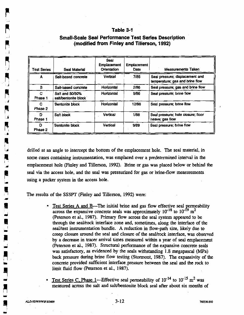
Table 3-1 Small-Scale Seal Performance Test Series Description
(modified from Finley and Tillerson, 1 992)
drilled at an angle to intercept the bottom of the emplacement hole. The seal material, in
some cases containing instrumentation, was emplaced over a predetermined interval in the
emplacement hole (Finley and Tillerson, 1992). Brine or gas was placed below or behind the
seal via the access hole, and the seal was pressurized for gas or brine-flow measurements
using a packer system in the access hole.
Test Series
A
B C
Phase 1
C Phase 2
D Phase 1
D Phase 2
The results of the SSSPT (Finley and Tillerson, 1992) were:
Seal Emplacement Orientation
Vertical
Horizontal
Horizontal
Horizontal
Vertical
Vertical
Seal Material
Salt-based concrete
Salt-based concrete
SaR and 50/50°h saltbentonite block
Bentonite block
SaR block
Bentonite block
Test Series A and B-The initial brine and gas flow effective seal bYbility across the expansive concrete seals was approximately 10-la to 10' m (Peterson et al., 1987). Primary flow across the seal system appeared to be through the seaUrock interface zone and, sometimes, along the interface of the seaVtest instrumentation bundle. A reduction in flow-path size, likely due to creep closure around the seal and closure of the sedrock interface, was observed by a decrease in tracer amval times measured within a year of seal emplacement (Peterson et al., 1987). Structural performance of the expansive concrete seals was satisfactory, as evidenced by the seals withstanding 1.8 megapascal (MPa) back pressure during brine flow testing (Stormont, 1987). The expansivity of the concrete provided sufficient interface pressure between the seal and the rock to limit fluid flow (Peterson et al., 1987).
15 2 Test Series C. Phase 1-Effective seal permeability of l(ri4 to 10- m was measured across the salt and salthentonite block seal after about six months of
Emplacement Date
7/85
2/86
9/86
12/90
1/88
9/89
Measurements Taken
Seal pressure; displacement and temperature; gas and brine flow
Seal pressure; gas and brine flow
Seal pressure; brine flow
Seal pressure; brine flow
Seal pressure; hole closure; floor heave; gas flow
Seal pressure; brine flow
brine testing (Torres and Howard, 1989). Structural measurements suggested that the saltlbentonite block seals did not behave significantly differently than did 100 percent salt block seals (Test Series D, Phase 1) over the time periods tested (Stormont and Howard, 1987).
Test Series D, Phase 1-Effective seal pexmeability from gas-flow test results showed that gas-flow rates across the salt-block seal exceeded the measuring capability of the equipment (Torres et al., 1991). Structural measurements, including seal pressure and borehole displacements, agreed with laboratory and modeling predictions. The crushed salt and salt block seals would provide little resistance to closure and little resistance to flow until the crushed salt has achieved 90 to 95 percent of the intact salt density (Holcomb and Shields, 1987; Sjaardema and Krieg, 1987).
18 2 Test Series C and D. Phase 2-Effective seal permeability of 10'17 to 1 0 m was measured across the 100 percent bentonite blocks after about two months of brine testing (Toms and Howard, 1990). A 2 order-of-magnitude decrease in effective seal permeability was observed after 150 days of brine testing. This decrease was likely due to the swelling of the bentonite over time. Gas testing was not performed, but gas flow rates were expected to be similar to the flow rates measured across the 100 percent salt block seals in Test Series D, Phase 1. Pressure measurements showed an increase in seal pressure (0.7 MPa) after about 300 days of brine testing (Torres and Howard, 1990).
The SSSPT have provided critical information on seal materials and performance that has
been used in the development of preliminary full-scale WIPP shaft and drift-seal designs.
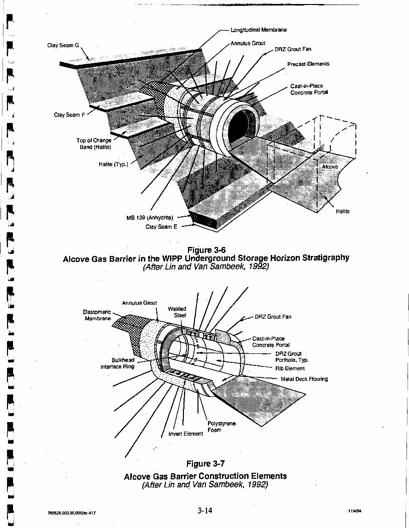
3.7.2.3 Alcove Gas Barrier Seal Design At one time, tests with radioactive wastes were planned to be conducted in the WIPP
underground. These tests included evaluation of gases generated by wastes emplaced in
mined alcoves. Barriers were designed for the entries into these alcoves to limit the gas
release during the testing program. The details of the design of this barrier system were
presented in Lin and Van Sarnbeek (1992) and are summarized below and in Figures 3-6 and
3-7.
The AGB was designed to isolate a test alcove at the WIPP and restrict gas flow. Figure 3-6
shows the AGB relative to the stratigraphy at the WIPP's underground disposal horizon (Lin
and Van Sarnbeek, 1992). The AGB is located in the access drift about 30 ft (9.2 m) from the test alcove. It consists of a 48-ft (14.6-m) long rigid sleeve, which houses three gas-tight
bulkheads. The inside diameter will accommodate the 10-ft (3.05-m) outside dianeter
- Longitudinal Membrane
Precast Elements
MB 139 (Anhydrite)
Figure 3-6 Alcove Gas Barrier in the WlPP Underground Storage Horizon Stratigraphy
(After Lin and Van Sambeek, 1992)
Annulus Grout
// / liven Element Foam
Figure 3-7
Alcove Gas Barrier Construction Elements (After Lin anc! Van Sambeek, 1992)
Flooring
bulkheads, which provide opening passages 6 ft (1.83 m) wide by 9 ft (2.74 m) high. The
bulkheads may be removed if required for experimental purposes or for remedial grouting.
The structural elements of the AGB are shown schematically in Figure 3-7. The rigid sleeve
consists of twelve 4-ft (1.2-m) long ring segments, each of which is made of four precast
elements. These in turn are composite structures that consist of a 1.25-inch- (3.2-centimeter-
[cm]) thick inner cylindrical shell made of 100 kips per square inch m i ) (690 MPa) alloy
steel and 16.75-inch- (42.5-cm-) thick concrete with an unconfined compressive strength of
10 ksi (69 MPa). The overall thickness of the lining is 18 inches (48 cm) to withstand the
design loading of 2,150 pounds per square inch (psi) (14.83 MPa), which is shared about
equally between the steel and concrete of the composite structure (Lin and Van Sambeek,
1992).
The design incorporated gas barriers to reduce potential leakage paths. These barriers consist
of an elastomeric membrane anchored to the rock salt in the annular space surrounding the
AGB, a seal-welded steel cylinder at the inside face of the AGB lining, and three transverse
membrane barriers within the lining at the locations of the bulkheads. The 3-inch (7.6-cm)
annular space outside the rigid sleeve and inside the elastomeric membrane is grouted with
nonshrink grout of 9 ksi (62 MPa) unconfined compressive strength. At the two ends of the
rigid sleeve, 3.5-ft- (1.07-m-) long reinforced concrete portals provide a transition from the
rectangular to the circular geometry (Lin and Van Sambeek, 1992).
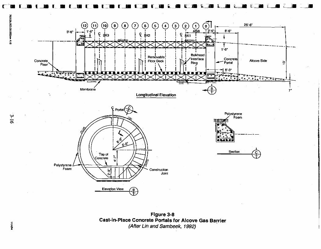
Figure 3-8 depicts the cast-in-place portals at the ends of the AGB. Numerical stress analysis
of the AGB design without the portals indicated that the ends of the sleeve will be subjected
to loading that exceeds a lithostatic pressure of 2,150 psi (14.83 MPa). An unrestrained
opening could close by 3 to 4 inches (7.5 to 10 cm) after 15 years. The portals were
included in the final design to provide a gradual transition of .the stiffness from the maximum
at the end of the circular rigid sleeve to zero at the rectangular unlined drift an and Van
Sambeek, 1992).
3.1.2.4 Recently Revised Panel Seal Conceptual Designs Van Sambeek et al. (1993a) presented the results from a study of various sealing alternatives
for WIPP seal design. These seql designs were for both the operational (35 years) and the
postclosure (lasting approximately 10,000 years) phases. The initial seal system design
presented by Nowak et al. (1990) and discussed in Section 3.1.2.1 above provides one type of
seal for each location to be sealed. The sealing alternatives developed by Van Sambeek et al.
/ I Membrane 7"
Longitudinal Elevation
Polystyrene Foam
Polystyrene
Section d
Figure 3-8 Cast-in-Place Concrete Portals for Alcove Gas Barrier
(After Lin and Sambeek, 1992)
(1993a) included seals that involved different sizes, shapes, materials, seal installation
schedules, elimination or addition of seal components, and remediation and maintenance
requirements.
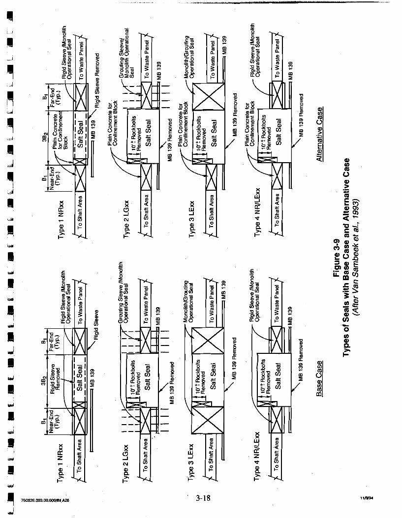
For panel-access drift seals, four design types were established based on "NOW" versus
"LATER" concepts and engineering requirements for the DRZ and MB 139. "NOW" design
concepts are seal designs that assume that the access drift has not yet been excavated and that
seal components can be emplaced immediately following access drift excavation. "LATER"
design concepts assume that the access drift has already been excavated in the past and that
the DRZ and fracturing of MB 139 have had ample time to occur. Each of the four design
types consists of two variations: a base case and an alternative case. Figure 3-9 shows the ,
two cases for each design type. The base-case seal for each design type has two identical
concrete monoliths, or bulkheads, designed to provide redundant operational period seals.
The alternative case seal for each design type has only one operational seal, and the near-end
(drift side) bulkhead of the base case seal is replaced by a plain concrete bulkhead solely for
confining the emplaced crushed salt in the center of the seal system. In both cases,
confidence for sealing during the operational period can be bolstered by remedial
mkntenance, ventilation; and monitoring measures at the access drift adjacent to the near-end
bulkhead (Van Sambeek et al., 1993a).
The rigid sleeve concept is founded on the assumption that a rigid sleeve is installed at the
future seal location immediately after excavation. A rigid sleeve is installed as soon as
possible after excavation to prevent some degradation of MB 139 and to arrest the
development of the DRZ in salt (Van Sambeek et al., 1993a). In the absence of a timely
placed rigid sleeve, the deformation in MB 139 and the development of the DRZ will likely
compromise the seal system or at least require remedial activities to achieve an adequate seal.
The LATER concepts assume that nothing is done to the excavation until after waste is
emplaced and the panel is ready to be sealed. Therefore, remedial grouting and/or excavation
of the DRZ and MB 139 would be necessary for these types of seals. The four basecase seal
designs from Van Sambeek et al. (1993a) are described briefly below.
In the first seal design type (NRxx), a rigid sleeve is installed in the seal area prior to further
development of the drifts and panel. After waste emplacement, the middle section of the
sleeve is removed and filled with crushed salt, while the end sections are filled with concrete.
The rigid sleeve is a steel shell and concrete composite structure similar to that described for
use in the WIPP AGB (Lin and Van Sambeek, 1992).
The DRZ in the salt around the bulkhead is expected to be healed so that the concrete
bulkheads can act immediately as operational seals. In the base case, the two bulkheads will
function as redundant operational seals. The outer rigid sleeve may serve as the core
structure for remedial grouting of the DRZ, if required.
In Lin and Van Sambeek's second seal design type (LGxx), nothing is done to the excavated
opening until the time for seal construction after waste emplacement. After waste
emplacement, the seal construction will begin with the placement of the grouting sleeves at
the bulkhead (monolith) locations. The sleeves provide resistance against the pressure loading
from the DRZ grouting. Grouting fans will be drilled through the shell plate through which
the DRZ will be grouted. The DRZ and MB 139 are then overexcavated in the middle
section between the grout sleeves. This overexcavation will be done by a custom-made
shearer, starting from the roof and proceeding down to the bottom of MB 139.
As with the second seal design type, in Lin and Van Sarnbeek's third seal design type (LExx)
nothing is done to the excavated opening until waste emplacement is complete. The seal
consists of two cast-in-place concrete monoliths at the ends and a salt seal in the center.
Prior to the seal construction, the DRZ around the seal area and MB 139 will be
overexcavated. This overexcavation will include the entire length of the seal system,
including the area for the concrete monoliths. An interface grouting system or longitudinal
membrane system will be emplaced around each monolith for an operational seal.
Lin and Van Sarnbeek's final seal design type combines the features of the first (NRxx) and
third (LExx) design types. Rigid sleeves are placed immediately after excavation in the areas
where the concrete monoliths or bulkheads will be placed. The area between the rigid sleeves
will be allowed to deform during waste emplacement, and the DRZ will be overexcavated
immediately prior to final seal emplacement. Crushed salt will be placed in the central part
of the seal system between the concrete bulkheads.
Hansen et al. (1993) presented alternative design concepts for the WIPP panel and drift seals
that considered only the requirements of the operational period. A design goal was presented
for limiting gas flow from the waste emplacement area to 7 x cubic feet per minute
(cfm). The operational period was assumed to be 35 years: 30 years for salt excavation and
waste emplacement and 5 years for room backfilling and underground decommissioning.
These seal designs were derived directly from the designs developed by Lin and Van
Sarnbeek (1992) discussed above. Hansen et al. (1993) did not consider long-term
requirements for the panel seals. This allowed evaluation of possible seal concepts for
operational period requirements alone, which involved performance criteria established by the
EPA under the RCRA. The principal operational function of the seal was to limit gas leakage
from the waste side of the panel to the main access drifts during repository operations. The
criteria for gas leakage assumed the panel contained VOCs characteristic of mixed waste. A
seal design requirement was established to a permeability of 6 x 10-l8 m2.
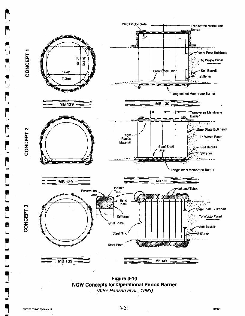
Two sets of operational seal design concepts were studied. As with Lin and Van Sambeek
(1992), Hansen et al. (1993) referred to them as the NOW seal designs and the LATER seal
designs. Figure 3-10 shows Hansen's three concepts of the NOW panel seal, in which a
sleeve is installed immediately after excavation to control the DRZ in the salt and to reduce
deformation of MB 139 underlying the seal. After waste emplacement in the panel, a
stiffened steel-plate bulkhead will be installed at the waste side to complete the operational
period seal. Both rigid and yielding (deformable) sleeves were considered. The concepts
considered are a cylindrical rigid sleeve built of precast members, a horseshoe-shaped
yielding sleeve, and a cylindrical steel ring surrounded by inflated tubes to act as another
form of yielding sleeve. The effectiveness of the panel seals can be monitored during the
operational period, and remedial grouting can be provided as required.
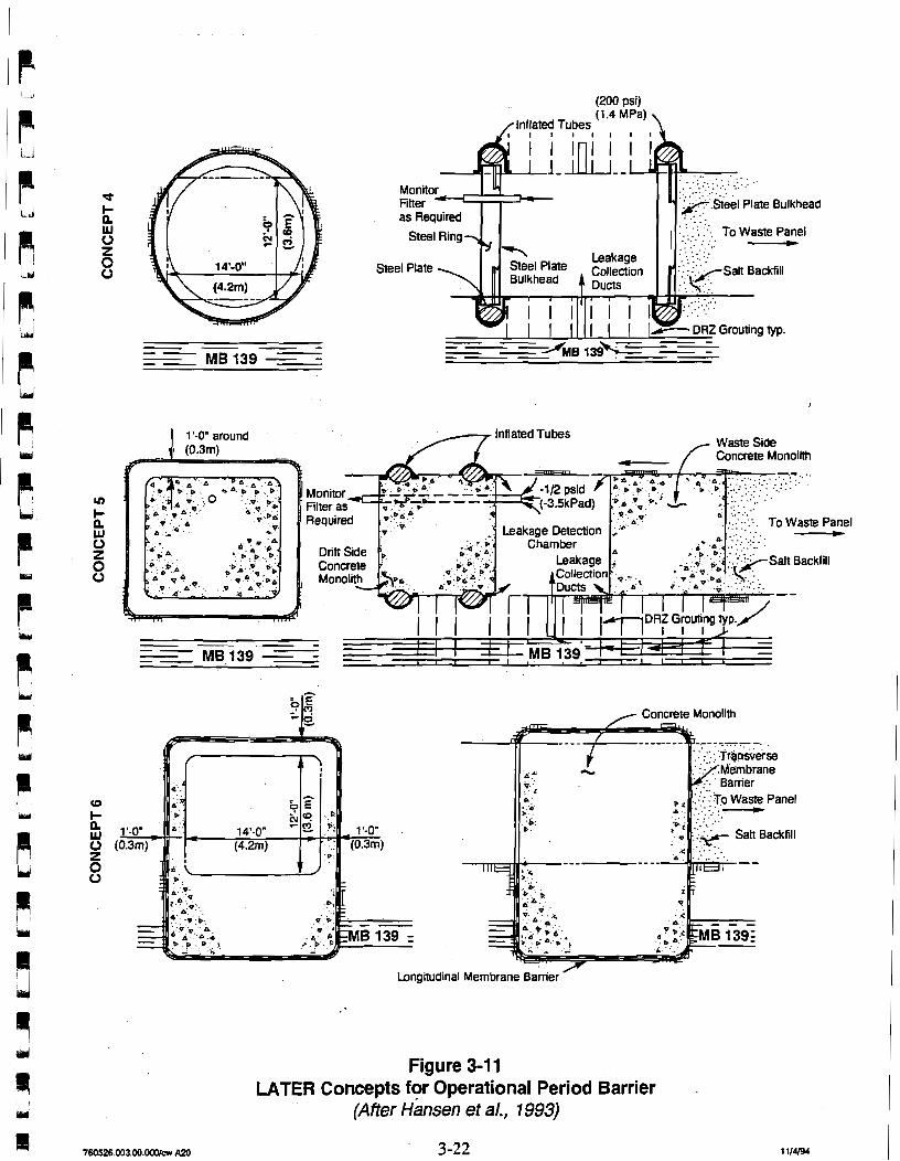
Hansen's three concepts for LATER seals are shown in Figure 3-1 1. The LATER seals
require no action until the time of panel closure. At panel closure, a significant DRZ is expected to have developed around the opening, which might have required rock bolts or other ground support for operational safety. Significant uplift of the unrestrained floor could
have taken place, fracturing MB 139. Concepts 4 and 5 show two bulkheads that could be
used to form a monitoring chamber. A monitoring chamber for use during the operational
period could be added to any of the concepts. Concept 6 is a single concrete monolith that is installed after excavation of the DRZ in salt and MB 139.
For a seal using two bulkheads, as illustrated in Concepts 4 and 5 (Figure 3-1 I), a monitoring
chamber can be formed between fie bulkheads and used for leakage detection or gas
collection. A leakage-collection system could be built at the center of the chamber for
monitoring leakage bough MB 139 or the clay seams. The drift-side bulkheads, as
illustrated in Figure 3-1 1, are equipped with inflated tubes to assure a reasonably airtight seal
Transverse Membrane
:*eel Plate Bulkhead
Longitudinal Membrane Barrier
. . .. .:. . ' . .A .
t' .....,,... . ..:.. :.:. ' . ' _.-_.. . . . _ . . .... , ..
/ :/isfeel Plate Bulkhead Rigid . -
plasic [ 1 1 1 l ~ ~ ~ . j . TO waste p z e l Material . ~ .. . .~ . .
.:../ Salt Backfill
..~. . . Stiffener
' Longitudinal Membrane Barrier
Figure 3-10 NOW Concepts for Operational Period Barrier
(After Hansen et al., 1993)
(200 psi)
-- --- - - - - --- - l i e i39iP=
Longitudinal Membrane Bamer '
Concrete Monolith
Figure 3-1 1 LATER Concepts for Operational Period Barrier
(Afier an sen et a/., 1993)
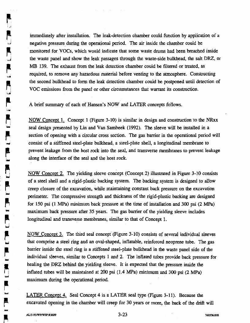
immediately after installation. The leak-detection chamber could function by application of a
negative pressure during the operational period. The air inside the chamber could be
monitored for VOCs, which would indicate that some waste drums had been breached inside
the waste panel and show the leak passages through the waste-side bulkhead, the salt DRZ, or
MI3 139. The exhaust from the leak detection chamber could be filtered or treated, as
required, to remove any hazardous material before venting to the atmosphere. Constructing
the second bulkhead to form the leak detection chamber could be postponed until detection of
VOC emissions from the panel or other circumstances that warrant its construction.
A brief summary of each of Hansen's NOW and LATER concepts follows.
NOW Concept 1. Concept 1 (Figure 3-10) is similar in design and construction to the NRxx seal design presented by Lin and Van Sambeek (1992). The sleeve will be installed in a
section of opening with a circular cross section. The gas barrier in the operational period will
consist of a stiffened steel-plate bulkhead, a steel-plate shell, a longitudinal membrane to
prevent leakage from the host rock into the seal, and transverse membranes to prevent leakage
along the interface of the seal and the host rock.
NOW Concewt 2. The yielding sleeve concept (Concept 2) illustrated in Figure 3-10 consists
of a steel shell and a rigid-plastic backing system. The backing system is designed to allow
creep closure of the excavation, while maintaining constant back pressure on the excavation
perimeter. The compressive strength and thickness of the rigid-plastic backing are designed
for 150 psi (1 MPa) minimum back pressure at the time of installation and 300 psi (2 MPa)
maximum back pressure after 35 years. The gas barrier of the yielding sleeve includes
longitudinal and transverse membranes, similar to that of Concept 1.
NOW Concept 3. The third seal concept (Figure 3-10) consists of several individual sleeves
that comprise a steel ring and an oval-shaped, inflatable, reinforced neoprene tube. The gas
barrier inside the steel ring is a stiffened steel-plate bulkhead in the waste panel side of the
individual sleeves, similar to Concepts 1 and 2. The inflated tubes provide back pressure for
healing the DRZ behind the yielding sleeve. It is expected that the pressure inside the
inflated tubes will be maintained at 200 psi (1.4 MPa) minimum and 300 psi (2 MPa)
maximum during the operational. period.
LATER Concept 4. Seal Concept 4 is a LATER seal type (Figure 3-1 1). Because the
excavated opening in the chamber will creep for 30 years or more, the back of the drift will
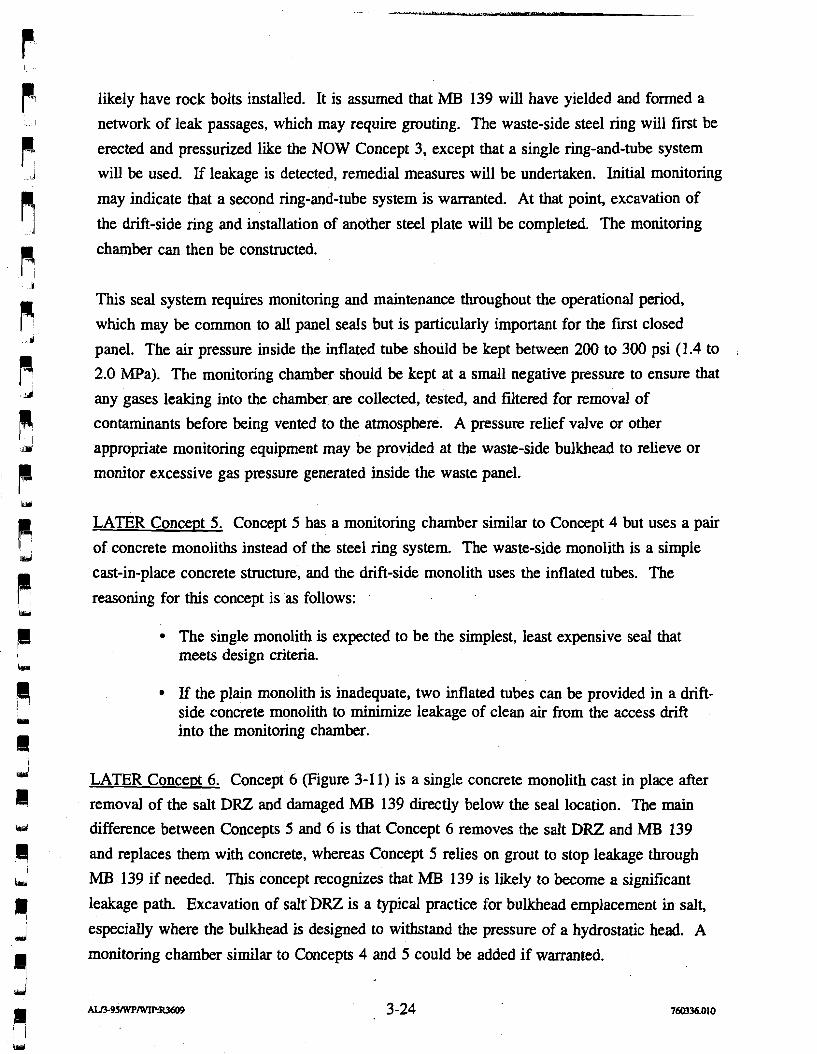
likely have rock bolts installed. It is assumed that MB 139 will have yielded and formed a
network of leak passages, which may require grouting. The waste-side steel ring will first be
erected and pressurized like the NOW Concept 3, except that a single ring-and-tube system
will be used. If leakage is detected, remedial measures will be undertaken. Initial monitoring
may indicate that a second ring-and-tube system is warranted. At that point, excavation of
the drift-side ring and installation of another steel plate will be completed. The monitoring
chamber can then be constructed.
This seal system requires monitoring and maintenance throughout the operational period,
which may be common to all panel seals but is particularly important for the first closed
panel. The air pressure inside the inflated tube should be kept between 200 to 300 psi (1.4 to ,
2.0 MPa). The monitoring chamber should be kept at a small negative pressure to ensure that
any gases leaking into the chamber are collected, tested, and filtered for removal of
contaminants before being vented to the atmosphere. A pressure relief valve or other
appropriate monitoring equipment may be provided at the waste-side bulkhead to relieve or
monitor excessive gas pressure generated inside the waste panel.
LATER Concept 5. Concept 5 has a monitoring chamber similar to Concept 4 but uses a pair
of concrete monoliths instead of the steel ring system. The waste-side monolith is a simple
cast-in-place concrete structure, and the drift-side monolith uses the inflated tubes. The
reasoning for this concept is as follows:
The single monolith is expected to be the simplest, least expensive seal that meets design criteria.
If the plain monolith is inadequate, two inflated tubes can be provided in a drift- side concrete monolith to minimize leakage of clean air from the access drift into the monitoring chamber.
LATER Concept 6. Concept 6 (Figure 3-11) is a single concrete monolith cast in place after
removal of the salt DRZ and damaged MI3 139 directly below the seal location. The main difference between Concepts 5 and 6 is that Concept 6 removes the salt DRZ and MB 139
and replaces them with concrete, whereas Concept 5 relies on grout to stop leakage through
MI3 139 if needed. This concept recognizes that MB 139 is likely to become a significant
leakage path. Excavation of salt bRZ is a typical practice for bulkhead emplacement in salt,
especially where the bulkhead is designed to withstand the pressure of a hydrostatic head. A
monitoring chamber similar to Concepts 4 and 5 could be added if warranted.
3.1.3 Panel Seal Concept Using Drilled and Grouted Cutoffs As stated by Cook and Case (1991), the main consideration in the design and construction of
a seal system is to reduce flow along the seal interface zones and through the disturbed zone
about excavations. Rock disturbance may be minimized by appropriate selection of
excavation techniques for removal of disturbed zones. Conceptual designs have been
advanced for keying the seal into the rock to provide a more effective barrier. These
concepts will require thought to ensure that the keys do not create an enlarged disturbed zone
due to the absence of support during construction.
Cook and Case (1991) indicated that a preferred method to treat the DRZ is to take advantage
of the ability of the salt to heal fractures when subject to confining stress. This requires the , emplacement of a structural seal that will not yield. After emplacement of such a structural
seal, stresses will build up on seal components. The stresses within the disturbed zone are
expected to build up to approximately 50 to 60 percent of the nominal lithostatic stress within
a 25-year period. This will result in reduction of permeability of the disturbed zone in the
salt as fractures close and heal.
As an alternative to waiting for the DRZ to heal, Cook and Case (1991) presented a panel
seal design option that could be utilized as a component of other panel seal designs discussed
previously. This concept uses drilled and grouted cutoffs to eliminate the DRZ or specific
fractured rock strata, such as MB 139. The cutoffs are a series of overlapping small-diameter
(approximately 6-inch [15-cm]) drillholes filled with grout, which forms a grout curtain across
the DRZ. Drillhole diameters are small enough so that they would not cause further
extension of the DRZ. The holes would penetrate through the part of the disturbed zone in
which the permeability is significantly increased (i.e., the length of the holes would probably
be 1 to 2 times the entry width). Each hole would be grouted immediately after drilling and
before adjacent holes are drilled. Overdrilling of previously grouted holes may be necessary
to ensure adequate overlap of holes and complete cutoff of the DRZ.
3.2 Ground Conditjons/Characterization
3.2.1 Disturbed Rock Zone Characterization Following the excavation of underground openings at the WIPP, a DRZ forms in the rock
surrounding the opening. The DRZ around these openings is delineated by the boundary at
which mechanical and hydrological properties have changed in response to the excavation. A
more fundamental definition of the DRZ is the volume of rock that experiences a change in
its pore structure in response to excavation (Stormont et al., 1991). The DRZ has been
characterized with visual methods, geophysical methods, in situ gas-flow measurements,
laboratory analysis, and numerical modeling.
The DRZ relative to the panel closure system is associated with four types of disturbances:
The underlying MB 139 The overlying and intersecting clay seams Dilated salt Fractured salt surrounding the access drift.
These zones develop primarily because of the creep of salt surrounding the access drift. As ,
the salt moves toward the opening, damage can occur as the more brittle interbeds (i.e.,
MI3 139) are deflected (bent) andfor the clay seams are caused to slip. Salt surrounding a
drift undergoes dilational (volumetric increase) deformation because of the stress
concentration caused by the excavation of the drift itself. With an accumulation of creep
deformation, the salt may also crack or separate along the bedding planes. In areas where the
stress states are favorable and the creep deformations are smaller, the salt remains essentially
intact and tight with an undisturbed permeability low enough (permeability less than m2, [Stormont et al., 19911) for the salt to be a barrier to flow. In the following sections, each of
these zones is described in t e r n of how and why it may become a flow path and the extent
of the disturbance.
3.2.1. 1 Marker Bed 139 The anhydrite of MB 139 is the closest major interbed to the panel and clrift-closure system
locations. MB 139 is a nominally 3 4 - (l-m-) thick stiff bed consisting of anhydrite and
halite. The anhydrite is brittle, unlike the viscoplastic WIPP salt. In its undisturbed state, it
is relatively tight, because natural fkactures and bedding features are closed or salt filled.
Excavation of the access drift removes the vertical stress and allows relaxation of the
fractures. Moreover, with time, the creep of the salt toward and into the drift causes upward
deflection, or heave, of the bed. As the bed deflects, the natural fractures and salt infilling
are disturbed, and new fractures may be generated. When fractures develop in MB 139, the
permeability of the interbed will increase significantly, and such fracturing is not expected to
heal naturally over the operational period of the panel-closure system. Grouting should
reduce the permeability; however, the effectiveness of grouting is diminished if the salt
continues to creep toward the excavation, resulting in further deformation and continued
fracturing of MB 139. The portion of the marker bed below pillars (unmined areas) is
believed to remain tight, based on measurements (described below) and rock mechanical
analyses (Van Sarnbeek et al., 1993b).
In situ gas flowlpermeability measurements made over test intervals that include MB 139
indicated the following (Stormont et al., 1987; Borns and Stormont, 1988):
Flow rates in MB 139 near the center of excavations of comparable age increased as the span of the drift increases. In four of seven tests conducted from the center of test rooms (33-ft [lo-m] span) in which the test intervals included MB 139, the transmissivity was so large that a gas pressure could not be sustained in the test interval.
Flow rates (i.e., transmissivities) increased as the age of the opening increased; however, the influence of span was more important.
Low flow rates measured in test intervals located near the edge of excavations were low, indicating that the marker bed remained tight when it was vertically confined by the pillars.
Single-phase brine and nitrogen permeabilities were measured in the laboratory for specimens
of MI3 139 taken from the underground workings at the WIPP. The test plan was designed to
provide data to evaluate the causes of spatial variations in permeabilities (Brodsky, 1994). 17 2 Permeabilities to gas ranged from approximately 1.8 x lo-'' to 2.5 x 10- m , and the
Klinkenberg-corrected equivalent liquid permeabilities ranged from 1.4 x 10-l8 to 17 2 17 2 1.6 x 10- m . Measured permeabilities to brine ranged from 4.4 x to 9.7 x 10- m .
Permeabilities to brine were higher, perhaps because of some specimen dssolution that
occurred during specimen saturation.
The measured permeabilities of intact specimens of MI3 139 to nitrogen and brine each
spanned approximately 2 to 2.5 orders of magnitude. The permeabilities measured in the
laboratory on cored specimens were considered representative of the "best" condition for
MI3 139 below the drift (i.e., in a stress-relieved condition). While the cored specimens
undoubtedly sustained drilling damage, the tested specimens also represented portions of
MB 139 that remained structurally competent.
From the brief description above,. two factors were involved in creating the MB 139 DRZ:
the stress relief from excavation and the subsequent deflection from salt creep. Because the
unmined salt on either side of the access drift continues to vertically confine the marker bed,
the extent of the DRZ is limited to the width of the drift. The disturbance is most severe in
the center of the drift and diminishes toward the ribs. It is expected that the disturbance will
be similar along the entire length of the drift.
Numerical analyses were conducted to evaluate the development and potential migration of
the DRZ. The potential for yielding (based on the Drucker-Praeger yield criterion) in
MI3 139 for two excavation geometries (one 14 by 12 ft [4.3 by 3.7 m] and one 25 by 12 ft
[7.6 by 3.7 m]) was examined by numerical analyses (Van Sambeek et al., 1993b). Because
initial elastic excavation has resulted in some fracturing and uplift for the anhydrite layer that
is only crudely modeled, results of the numerical study were qualitative in assessing structural
infraction. The numerical analysis did not predict fracturing until ten years after excavation
for the 14- by 1 2 4 (4.3- by 3.7-m) opening, and the severity of damage continued to increase , for the duration of the simulation. By 40 years, most of the marker bed within 33 ft (10 m)
of the excavation centerline showed a high potential for yielding. For the 25- by 1 2 4
(7.6- by 3.7-m) excavation, yielding in the marker bed was possible within the first year after
excavation. Similar to the smaller excavation, the potential for yielding in the marker bed
continued to increase throughout the duration of the simulation.
3.2.1.2 Clay Seams The term "clay seams" is herein used to encompass the stratigraphic markers (thin clay and
anhydrite bedding features) and bedding separations (off-set cracks) that develop in the roof
and floor because of salt creep. These stratigraphic markers are believed to be tight in their
natural compressed state. Excavation of the access drift (1) relieves the vertical stress in
regions above and below the drift, (2) allows shear and flexural displacements across the
seam because of creep, and (3) exposes the seams to dehydration. Each of these may cause
an enhanced permeability or transmissivity through the seams. Ongoing creep in the roof and
floor salts may cause separation along bedding features in the roof and floor. These features
can be broad and continuous along the length of the drift and can open to measurable
apertures.
Characterization of the DRZ around the clay seam interbeds has not been performed. It is
possible that the zone of damage outside the seam itself is small, because the "clay" is weak
and will yield before allowing shearing stresses to build to the point where the surrounding
rock (salt) is damaged (Van Sambeek et al., 1993b)
Disturbance of the clay seams and offsets along bedding features will occur as discrete
features. Observations in vertically-up monitoring boreholes that penetrate Anhydrite Seam B (clay G) include:
Shear displacements or offsets often develop along the claylanhydrite boundary of Seam B. About 0.4 inch (1 cm) of horizontal shear displacements is typically seen within one year of drilling of the borehole. Such offsetting was found in more than half of all boreholes and was more than twice as likely to occur near the edge of an excavation compared to the center (DOE, 1988).
Vertical separations can occur at Seam B and are more likely to occur near the center of the excavation than near the edge (DOE, 1988).
Gas flowlpermeability measurements made from vertical boreholes over intervals '
that include Seam B result in very high flows when the test interval is above the center of the excavation and is consistently many orders of magnitude lower when the test interval is near the edge or removed from the excavation (Stormont et al., 1987). The magnitude of the flow, and by inference the size or number of separations, increases as the size of the excavation increases and as the age of the excavation increases. For example, above the center of test rooms more than two years old, the permeability of the test intervals that include Seam B was so great that a gas pressure could not be sustained.
Gas flowlpermeability measurements in the salt layer itself in the immediate roof indicate a permeabili on the order of lo-'-, consistently greater than the r permeability of m2 of "undisturbed" salt more than 16 ft (5 m) from an
'excavation. The permeability is not so high to suggest fracturing is occurring but is consistent with permeability measurements made on dilated salt subjected to highly deviatoric, low mean-stress conditions (Peach et al., 1987; Horsemen, 1988). Limited tracer gas measurements indicate the flow paths are larger in the vertical direction than the horizontal direction in the center of the drift.
3.2.1.3 Dilated Salt With regard to flow in the DRZ in salt, the most significant parameter is the permeability of
the disturbed salt. The rate at which the permeability increases from its intact salt value to its
damaged value has not been measured, but it seems reasonable to expect that the process is
strain-dependent, that is, dependent on actual deformation of the salt rather than the stress on
it. Excavation of the drift changes the stress distribution in the salt surrounding the opening.
The modified stress states can cause both instantaneous disturbance of the salt integrity by
fracturing processes and time-dependent damage as the salt creeps into the opening. This
disturbance is subtle and is differentiated from the larger-scale cracking described in association with the clay seams. The salt DRZ can be described as grain boundary opening
and microcrack generation manifested as volumetric strain. The effect is an increase in
permeability as porosity is generated and interconnected. Based on measurements by
(Stormont [1990, 1991]), the permeability may increase by several orders of magnitude from
nominally m2 for undisturbed salt.
Within the first meter of most excavations, some fractures parallel to the drift are observed
from boreholes at the midheight of the rib (DOE, 1988; Stormont, 1988). In this region, the
permeabilities are generally greater (about 10-l7 m2) than at any other location in the salt.
Between 3 and 6 ft (1 and 2 m) into the rib, permeabilities decrease to the 10-l9 m2 level and
below; beyond 6 ft (2 m), the permeabilities rapidly decrease to the value associated with
intact salt m2) (Stormont, 1990). I
Two numerical modeling analyses were performed to predict the extent of the DRZ around
drift and panel excavations at the WIPP that are left open for 40 years after excavation. The
DRZ was assessed in the salt surrounding the excavation. To bracket the DRZ for all drift
and panel excavations, both the smallest (14- by 1 2 4 r4.3- by 3.7-m) and the largest (25- by
1 2 4 r7.6- by 3 . 7 4 ) excavation sizes were evaluated (Van Sambeek et al., 1993b). The
largest panel access drift that will require an operational period closure system is
approximately 12 by 20 ft (3.7 by 6.1 m).
A quantity termed the "damage factor" was used to illustrate the extent of the DRZ. The
damage factor is the ratio of the predicted deviatoric stress and the deviatoric stress state at
the same mean stress that would produce dilation in salt based on laboratory core testing
(Ratigan et al., 1991). A damage factor value of 1.0 is the limit stress state for dilation to
occur. Dilation (and hence, permeability) is expected to increase with increasing damage
factor values. On the other hand, dilation is not expected for damage factors less than 1.0. It
must be recognized that damage factors are time-dependent. Therefore, regions that initially
dilate can reheal if a more favorable stress state occurs later. Healing is expected when the
damage factor becomes less than 1.0 (i.e., as the damage factor decreases, the expectancy for
healing increases). Qualitatively, it is also expected that the lower the damage factor value,
the faster the healing will occur.
Contours of the damage factor were shown immediately after excavation, after 1 year, and
after 40 years for a 14- by 12-ft (4.3- by 3.7-m) rectangular excavation. Immediately after
excavation, a significant amount of salt surrounding the excavation experiences stresses,
which will cause damage. Within 1 year after excavation, the damaged zone is almost
completely developed. Only very small increases in the cross-sectional area of the dilated salt
zone in the WIPP salt are predicted between 1 and 40 years. The fully developed dilated
zone for the 14- by 1 2 4 (4.3- by 3.7-m) excavation extends from the floor of the excavation
to MI3 139. The DRZ extends a maximum of approximately 3 ft (1 m) horizontally into the
pillar and 5 ft (1.5 m) above the excavation.
Similar to the 14- by 1 2 4 (4.3- by 3.7-m) excavation, the contours of the damage factor for a
25- by 12-ft (7.6- by 3.7-m) rectangular excavation show that most of the DRZ is developed
during the first year after excavation. However, growth of the DRZ above the excavation
over the 40 years is somewhat larger than that seen for the smaller drift. The fully developed
dilated salt zone for the 25- by 1 2 4 (7.6- by 3.7-m) excavation extends from the floor of the , excavation to MB 139. The dilated salt zone extends to a maximum of approximately 3 ft
(1 m) horizontally into the pillar and 9 ft (2.75 m) above the excavation.
Low-angle fractures and vertical fractures are observed at several locations in the WIPP underground. These vary from tight fractures to visibly open fractures. The open fractures
present an unrestricted flow path for gases and fluids and, as such, do not lend themselves to
the type of permeability measurements performed elsewhere.
Visual observations indicate that the fracturing of the salt extends to the first discontinuity
encountered, which is generally Seam B in the roof and MB 139 in the floor. If this
fracturing is observed in the floor or roof, it could be assumed that separations or open
fractures also exist in the intersecting beds and that a continuous flow path exists for some
unknown distance along the length of the drift. It is expected that these fractures are contained within the excavation itself and do not extend into the pillars.
3.2.2 Fracture ~Wechanisms Because design concepts must be tied to the development of fractures and clay seam
separation, the following provides a brief discussion of underground movements and where
they occur. These observations of ground fracturing were made in the Site and Preliminary
Design Validation (SPDV) facility and apply to underground movements elsewhere.
After rooms or entries were initially excavated in MarchIApril 1983, the test rooms underwent
time-dependent closure and showed no evidence of fracture development other than surficial
spding of the pillars. Yet, during 1985, drillhg in Test Room 3 provided evidence of
excavation-induced fractures. These fractures were surveyed and have been reported
previously (DOE, 1986a; DOE, 1986b). The surveys showed that bed separation was
occurring at the anhydritelsalt contact in the roof and floor and that fracturing occurred in the
salt strata.
In 1987, deteriorating roof conditions in Test Room 2 were observed. The room was not
supported, but monitoring continued to document its deterioration with time. Later that year,
bed separation in the roof of Test Room 1 started to accelerate. These observations led to the
installation of additional instrumentation to monitor the geomechanical performance in Test
Rooms 1 and 2. In general, the fracturing observed in the rooms that has some application to
the panel entries are as follows:
Vertical surficial fractures in pillars. I
Low-angled (relative to horizontal) fracturing that develops from the riWroof and riblfloor lines. These fractures may be filled with sheared material. Floor fractures may intersect the underlying anhydrite layer. Roof fractures can occur to the overlying anhydrite 'b'lsalt contact.
Subhorizontal fractures that develop within the first 18 inches (45 cm) of the roof. These provide the "drummy ground" that has been observed throughout the underground. These fractures are generally closed and show little evidence of relative displacement.
Bed separation that develops at the anhydrite 'b' interface in the roof.
Vertical surficial spalling in the roof that probably develops because of restraint imposed by remedial bolting. The restraint causes tensile failure of the salt in localized areas.
Low-angled (relative to horizontal) shear fractures that are visibly exposed laterally across the roof.
These fractures can be classified as follows (Figure 3-12):
Feature A, shallow dish-shaped floor fractures and deeper transverse fractures in the MB 139 below the floor
Feature B, pillar or sidewall spalling and fracturing
Feature C, roof sep&ation and flexure at clay seams
Feature D, transverse fractures in the roof.
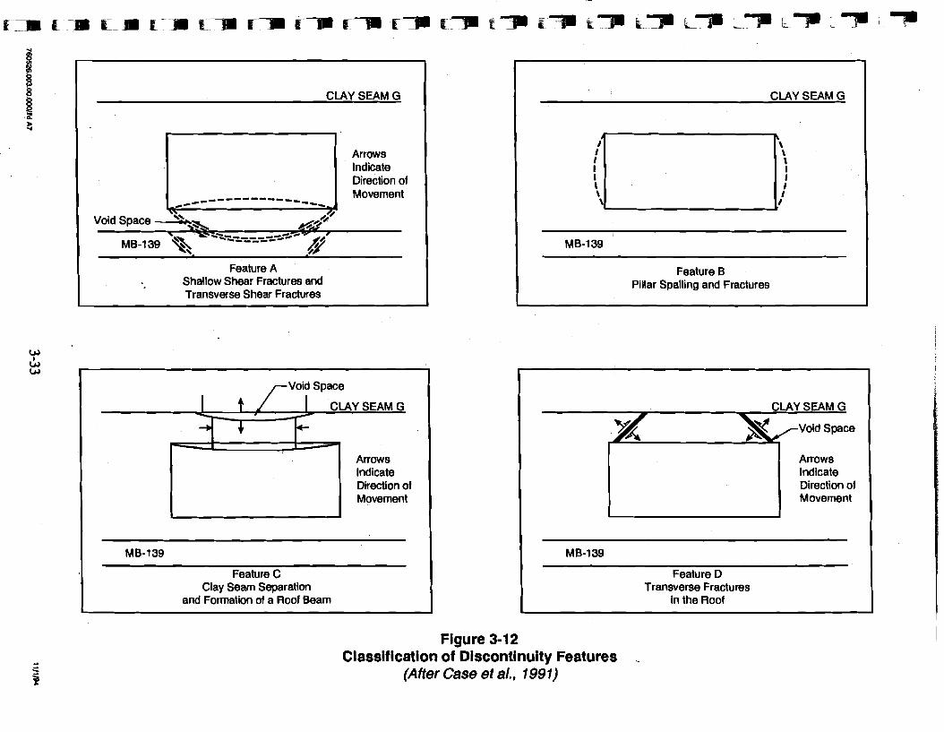
CLAY SEAM G
Arrows lndicate Direction of Movement
Void Space --z-------**
MB-139 --,,-e- .@ Feature A
Shallow Shear Fractures and Transverse Shear Fractures
I CLAY SEAM G
+ 4- - C
Arrows lndicate Direction of Movement
MB-139
Feature C Clay Seam Separation
and Formation of a Roof Beam
7
CLAY SEAM G
I I I \ I \ I \ I :Ii
MB-139
Feature B Pillar Spalling and Fractures
CLAY SEAM G
*Void Space
Arrows lndicate Direction of Movement
MB-139
Feature D Transverse Fractures
in the Roof
Figure 3-12 Classification of Discontinuity Features .
(After Case et a/., 1991)
The spatial correlation of these features in the SPDV test rooms and the adjacent blind drifts
is illustrated in Figure 3-13. Floor fracturing developed in most rooms and the connecting
N1420 Drift. Pillar spalling is prevalent only at room/access drift intersections.
Also, it would appear that bed separation occurred at the intersections with access drifts
(N 1100 and N1420), where adjacent blind drifts have been excavated at the north end of Test
Room 1 and at the south end of Test Room 2. These mechanisms were noticeably absent
from the intersection of the Nl 100 access drift with Test Rooms 3 and 4, and the smaller
adjacent alcove (Room 12) and the access drift to Room H.
Note that the panel entry widths of 25 and 14 ft (7.6 and 4.3 m) are less than the room
widths of 33 feet (10 m). Therefore, the mechanisms involving flexure are less likely to
occur for the panel entries or would occur at later times.
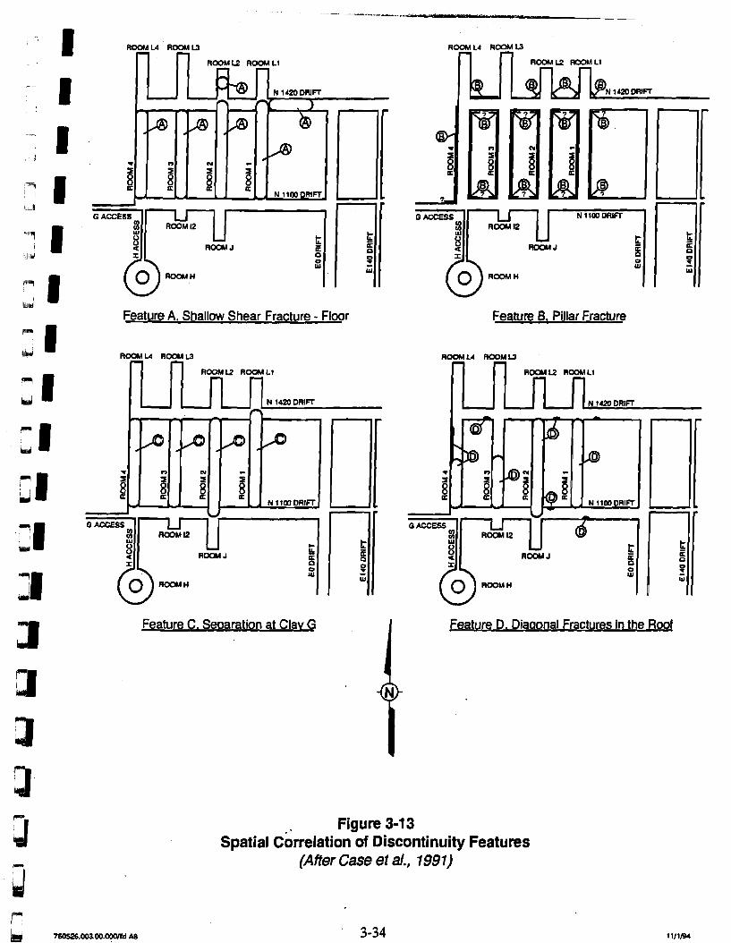
Feature A, Shallow Shear Fracture - Floor
ROOMU ROOMW
ROOMU ROOM L1
r ,
4 4 4
T C) N
a a
= i C. , , N 1100 DRIFT
U C ACCESS
8 - a ROOM J
t I 6
0 W
Feature C. Se~aration at Clav G
Feature B, Pillar Fracture
Feature D. Diaaonal Fractures in the Roof
I-
Figure 3-13 Spatial ~srrelation of Discontinuity Features
(Affer Case et a/., 1991)
(1, 4.0 Design Considerations for a Panel Closure System u
This chapter presents design considerations for a panel closun system. The f i t section dbb
presents migration mechanisms and design considerations for containment systems. The
second section presents a VOC migration release model considering the unrestricted
mass-flow release rate of VOCs to the land withdrawal boundary and compares this
mass-flow rate with the migration mass-flow rate limit for the nine VOCs that make up 99
percent of the health-based risk. The third section describes concepts for containment of a
F methane explosion. The fourth section describes the gas flow model for restricting flow over
'LY~Y~ the operational period and what could be expected from a panel barrier system.
IL II Chapter 2.0 presents both the design criteria and the design basis for panel closure systems.
The two critical elements in satisfying the regulations are (1) the control of the concentrations
of the VOCs to satisfy health-based levels for various compounds at the land withdrawal
boundary and (2) avoiding a hazardous working environment due to the occurrence of an
explosive mixture of methane. The three methods that are analyzed in this report for
satisfying the regulations are:
Use of the existing ventilation system to reduce the concentrations of VOCs exiting the WIPP underground
Providing safe working conditions by isolating areas of possible explosive methane mixtures with structural barriers able to withstand a methane explosion
Restriction of VOCs from entering the ventilation air stream by constructing barriers.
lpll For each method, the migration mechanism within the waste containers is a significant design
consideration. Section 4.1 discusses the processes and rates of gas generation. Y
F 4.1 Migration Mechanisms pri Several processes within the waste containers can provide a significant driving force for
VOC migration. After panel closure, the void space within the panel will be reduced due to
bpi creep closure. Gases generated within waste containers will tend to flow along a pressure
gradient out of the containers, through the barriers, and into the ventilated drifts. VOCs
present in the headspace will be carried along with this flow of gas. One of the key b
r, parameters controlling the rate at which VOCs will migrate from a closed panel into the
ventilated drifts by this process are the overall gas-generation rate within the waste containers
and creep closure of the panel rooms. Besides gas generation and creep closure, the only other credible processes that can lead to the migration of these VOCs out of the waste containers, through the panel barriers, and into the ventilated access drifts are:
Diffusion Barometric pumping.
These other mechanisms are considered in the following discussion.
4.1.1 Gas Generation Three processes that can generate gas within the waste containers are:
Anoxic corrosion Radiolysis Microbial degradation.
The contributions of these three processes to gas generation during the operational period of the repository are discussed below.
4.1.1.1 Anoxic Corrosion Two types of corrosion can occur in the WIPP environment: oxic and anoxic. Oxic
corrosion occurs in the presence of oxygen and can be thought of as:
where FexOy is some form of iron oxide (Fe203 or Fe30d). This reaction will preferentially occur if oxygen is present in the room atmosphere. The net effect of this reaction is to consume atmospheric oxygen, resulting in a decrease in panel gas pressure of up to 12 percent. This process of gas consumption is conservatively assumed to be negligible in
the analysis.
After the above reactions have consumed the available free oxygen, anoxic corrosion can then
occur, but only if moisture is present. A simplified anoxic corrosion reaction can be thought of as:
Other anoxic corrosion reactions that are possible involve the production of iron hydroxide
[Fe(OH)2] or iron oxy-hydroxide [FeOOH]. The exact reaction(s) that will occur are currently uncertain, but all anoxic corrosion reactions produce hydrogen gas and consume
water in the process. These anoxic corrosion reactions cannot occur in the absence of
moisture.
Brush (1991) has proposed a range of hydrogen generation rates in a humid environment of
0 to 1 moleddrudyear. It should be kept in mind that Brush (1991) assumed that a humid
environment would be maintained by a pool of free brine on the floor of a room. The rate
limiting step is the vapor-phase transport of water molecules from the pool to the metal
surfaces suspended above the pool. No such pool of brine is expected to be present in a
panel during the operational period of the facility. Observations of brine occurrences show
that limited amounts of brine do appear on freshly excavated faces, but these weeps and
encrustations cease to form after a few years. It is possible that the waste itself may contain
enough moisture to generate some hydrogen, but this is expected to be a self-limiting process,
because this moisture will be consumed by the corrosion reactions.
It is therefore highly unlikely that significant amounts of hydrogen will be generated during
the operational period, because of the lack of a credible source of moisture required to drive
this gas-generation process. The gas-generation rates recommended by Brush (1991) were
used in the 1991 and 1992 performance assessments (SNL, 1991; 1992). Since then, SNL
revised these estimated rates. These revised rates,'based on the results of ongoing
experiments, are discussed in Brush (1993; 1994). For hydrogen generation from anoxic
corrosion under humid conditions, Brush (1993; 1994) recommends a "best estimate" of
0 moles/drudyear. This reduction in the "best estimate" rate from 0.1 to 0 moleddrum/year
is based on experiments by Telander and Westerman (1993), who observed no detectable
hydrogen generation or corrosion in 12- and 24-month experiments in a one-atmosphere
humid environment. The value of 0 moles/drum/year from Brush (1993; 1994) is used in the
panel design analysis.
4.1.1.2 Radiolysis Estimates of radiolytic gas-generation rates in a humid environment are not available, but they
have been estimated for an inundated environment from radiolysis of brine. These estimates,
provided by Brush (1991), range from 1 x 10" to 1 x lo-' moleddrudyear, with median
value of 1 x lo4 moleddrudyear. Radiolytic gas-generation rates in a humid environment
are expected to be orders of magnitude lower than radiolytic gas-generation rates in an
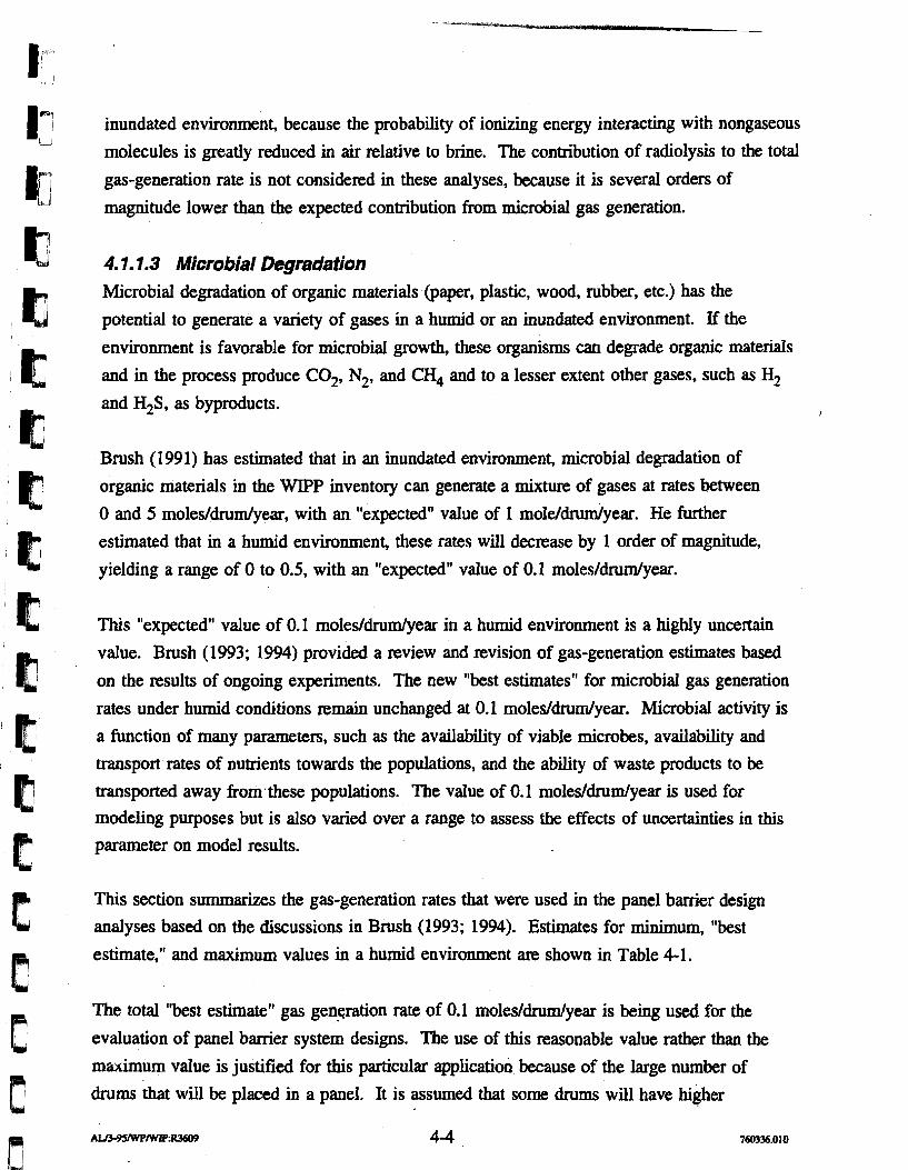
inundated environment, because the probability of ionizing energy interacting with nongaseous
molecules is greatly reduced in air relative to brine. The contribution of radiolysis to the total
gas-generation rate is not considered in these analyses, because it is several orders of
magnitude lower than the expected contribution from microbial gas generation.
4.1.1.3 Microbial Degradation Microbial degradation of organic materials (paper, plastic, wood, rubber, etc.) has the
potential to generate a variety of gases in a humid or an inundated environment. If the
environment is favorable for microbial growth, these organisms can degrade organic materials
and in the process produce C02, N2, and CH4 and to a lesser extent other gases, such as H2 and H,S, as byproducts. I
Brush (1991) has estimated that in an inundated environment, microbial degradation of
organic materials in the WIPP inventory can generate a mixture of gases at rates between
0 and 5 moles/drum/year, with an "expected" value of 1 moleldruxdyear. He further
estimated that in a humid environment, these rates will decrease by 1 order of magnitude,
yielding a range of 0 to 0.5, with an "expected" value of 0.1 moles/drum/year.
This "expected" value of 0.1 moles/drum/year in a humid environment is a highly uncertain
value. Brush (1993; 1994) provided a review and revision of gas-generation estimates based
on the results of ongoing experiments. The new "best estimates" for microbial gas generation
rates under humid conditions remain unchanged at 0.1 moleddrudyear. Microbial activity is
a function of many parameters, such as the availability of viable microbes, availability and
transport rates of nutrients towards the populations, and the ability of waste products to be
transported away from,these populations. The value of 0.1 moleddrum/year is used for modeling purposes but is also varied over a range to assess the effects of uncertainties in this parameter on model results.
This section summarizes the gas-generation rates that were used in the panel bamer design
analyses based on the discussions in Brush (1993; 1994). Estimates for minimum, "best
estimate," and maximum values in a humid environment are shown in Table 4-1.
The total "best estimate" gas generation rate of 0.1 moleddrum/year is being used for the
evaluation of panel barrier system designs. The use of this reasonable value rather than the
maximum value is justified for this particular application because of the large number of
drums that will be placed in a panel. It is assumed that some drums will have higher
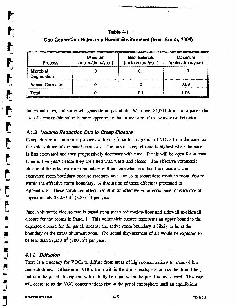
Table 4-1
Gas Generation Rates in a Humid Environment (from Brush, 1994)
individual rates, and some will generate no gas at all. With over 8 1,000 drums in a panel, the
use of a reasonable value is more appropriate than a measure of the worst-case behavior.
4.1.2 Volume Reduction Due to Creep Closure Creep closure of the rooms provides a driving force for migration of VOCs from the panel as the void volume of the panel decreases. The rate of creep closure is highest when the panel
is first excavated and then progressively decreases with time. Panels will be open for at least
three to five years before they are filled with waste and closed. The effective volumetric
closure at the effective room boundary will be somewhat less than the closure at the
excavated room boundary because fractures and clay-seam separations result in room closure
within the effective room boundary. A discussion of these effects is presented in
Appendix B. These combined effects result in an effective volumetric panel closure rate of
approximately 28,250 ft3 (800 m3) per year.
A
Process
Microbial Degradation
Anoxic Corrosion
Total
Panel volumetric closure rate is based upon measured roof-to-floor and sidewall-to-sidewall closure for the rooms in Panel I. This volumetric closure represents an upper bound to the
expected closure for the panel, because the active room boundary is likely to be at the
boundary of the stress abutment zone. The actual displacement of air would be expected to
be less than 28,250 ft3 (800 m3) per year.
4.1.3 Diffusion There is a tendency for VOCs to diffuse from areas of high concentrations to areas of low
concentrations. Diffusion of vocs from within the drum headspace, across the drum filter,
and into the panel atmosphere will initially be rapid when the panel is first closed. This rate will decrease as the VOC concentrations rise in the panel atmosphere until an equilibrium
. Maximum
(rnoles/drurn/year)
1 .O
0.06
1.06
Minimum (rnoles/dnrm/year)
0
0
0
Best Estimate (rnoles/dnrrn/year)
0.1
0
0.1
level is reached. Once equilibrium is reached, the only change that would occur would be the
result of diffusion of VOCs across the two panel closures' access-drift ventilation stops.
Diffusion of VOCs from a closed panel into the ventilated drift is considered for modeling
purposes to be insignificant relative to the effects of gas generation.
4.74 Barometric Pumping Fluctuations in the barometric pressure within the underground facility are induced by
changes in weather at the land surface. Also, they occur due to changes in the ventilation
rates in the underground. Pressure changes in the underground facility will induce pressure
changes in a closed panel, causing small amounts of alternating compression and expansion of
the panel atmosphere. This pumping process, when coupled with diffusion, can induce some
VOC migration across the panel barriers but only to a limited extent over a time cycle. The
effects of barometric pumping on the migration of VOCs from a closed panel into the
ventilated drift are considered for modeling purposes to be insignificant relative to the effects
of gas generation.
4.2 Model for Unrestricted Flow of VOCs A model for the unrestricted flow of VOCs was developed to predict the mass flow rates of
VOCs from the closed areas based on the health-based level concentrations at the 16-section
land withdrawal boundary and to compare this mass flow rate to a migration limit for VOCs.
As gas generation and panel volumetric creep closure proceed, a mixture of gases containing
the VOC concentrations flows from each waste container. It is assumed for the VOC
unrestricted flow model that the headspace concentrations serve as a constant source of
VOCs. This assumption is highly conservative, because most containers only have trace
quantities of VOCs either trapped in the headspace or adsorbed on the surfaces of the various waste forms. It is believed that only a small number of waste containers have significantly greater sources of VOCs, such as a solvent-soaked rag or a can containing residual partially dried paint. Only these waste containers have a likelihood of maintaining a constant headspace VOC concentration as gas generation proceeds. However, the exact proportion of
waste containers with higher VOC concentrations versus those with trace quantities is
currently unknown. These data are based on results of the characterization of approximately 500 TRU mixed waste drums at the Idaho National Engineering Laboratory (INEL) and
Rocky Flats.
The VOCs migrate due to advection from volumetric closure of the panel void space at a rate
of about 28,250 $ (800 m3) per year. Gas generation for the waste inventory at a rate of
0.1 mole per drum per year (8,200 moles per panel per year) results in a volumetric flow rate
of 7,060 $ (200 m3) per year. Because flow is unrestricted, the VOCs migrate under a
pressure of one atmosphere. Other assumptions in the unrestricted model are:
Any gases released into the mine atmosphere would be reduced in concentration by 460,000' cfm of uncontaminated air. The mass flow rate of individual VOCs from individual panels following their closure is summed to determine the mass flow rate of VOCs through the exhaust shaft.
This calculation considers the schedule for closure of individual panels as illustrated in Figure 4-1 (Westinghouse, 1995b) during the operational life of the WIPP. The VOC mass flow rate changes with time, with the maximum mass flow release rate occurring after 10 panel equivalents have been closed after about 25 years.
Each VOC is analyzed in the calculations. Carbon tetrachloride is the most restrictive VOC in terms of satisfying the health-based levels for individual VOCs.
Open panels of waste will not be considered as a source contributing to the emissions for a no-migration demonstration. Only emissions from the closed panels will be required to be considered as sources for the demonstration.
Considering only advection to result in the migration of VOCs the mass balance relationship
is:
where
Cp = Head space concentration for an individual VOC
Qp = Flow rate of VOCs fiom the panel that may vary with time
Qs = Underground ventilation flow rate for the.exhaust shaft
Ces = Concentration of VOCs at the exhaust shaft.
Air dispersion modeling is used for evaluating the receptor concentrations at the 16 section
land withdrawal boundary based upon the air exhaust shaft source term. The air dispersion
"I'hc design ventilation rate for the WIPP underground is 425,000 standard cfm (12,035 standard m3 per minute) under standard temperature and pressure conditions of 25 degrees Celsius and 1 atmosphere. The ventilation flow rate of 460,000 cfrn (13,025 m3 per minute) is the observed ventilation rate at the repository horizon under actual temperature and pressure conditions.
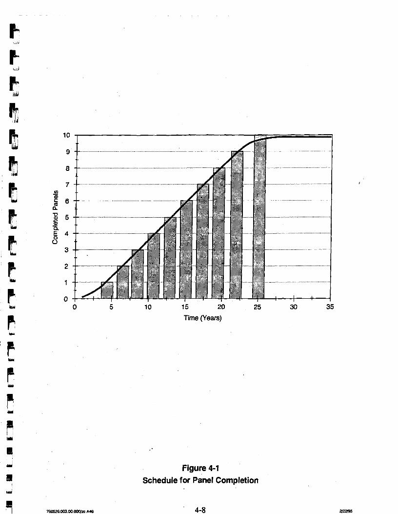
0 5 10 15 20 25 30 35
Time (Years)
Figure 4-1 Schedule for Panel Completion
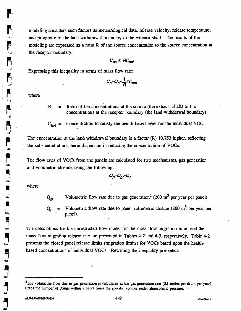
modeling considers such factors as meteorological data, release velocity, release temperature,
and proximity of the land withdrawal boundary to the exhaust shaft. The results of the
modeling are expressed as a ratio R of the source concentration to the source concentration at
the receptor boundary:
'es RChbl
Expressing this inequality in terms of mass flow rate:
1 cp*Qp*xschbl
where
R = Ratio of the concentrations at the source (the exhaust shaft) to the concentrations at the receptor boundary (the land withdrawal boundary)
Chbl = Concentration to satisfy the health-based level for the individual VOC.
The concentration at the land withdrawal boundary is a factor (R) 10,753 higher, reflecting
the substantial atmospheric dispersion in reducing the concentration of VOCs.
The flow rates of VOCs from the panels are calculated for two mechanisms, gas generation
and volumetric closure, using the following:
QfQgr+QC
where
Q, = Volumetric flow rate due to gas generation2 (200 m3 per year per panel)
Q, = Volumetric flow rate due to panel volumetric closure (800 d per year per panel).
The calculations for the unrestricted flow model for the mass flow migration limit, and the
mass flow migration release rate are presented in Tables 4-2 and 4-3, respectively. Table 4-2
presents the closed panel release limits (migration limits) for VOCs based upon the health-
based concentrations of individual VOCs. Rewriting the inequality presented:
volumetric flow due to gas generation is calculated as the gas generation rate (0.1 moles per dnun per year) times the number of drums within a panel times the .specific volume under atmospheric pressure. .
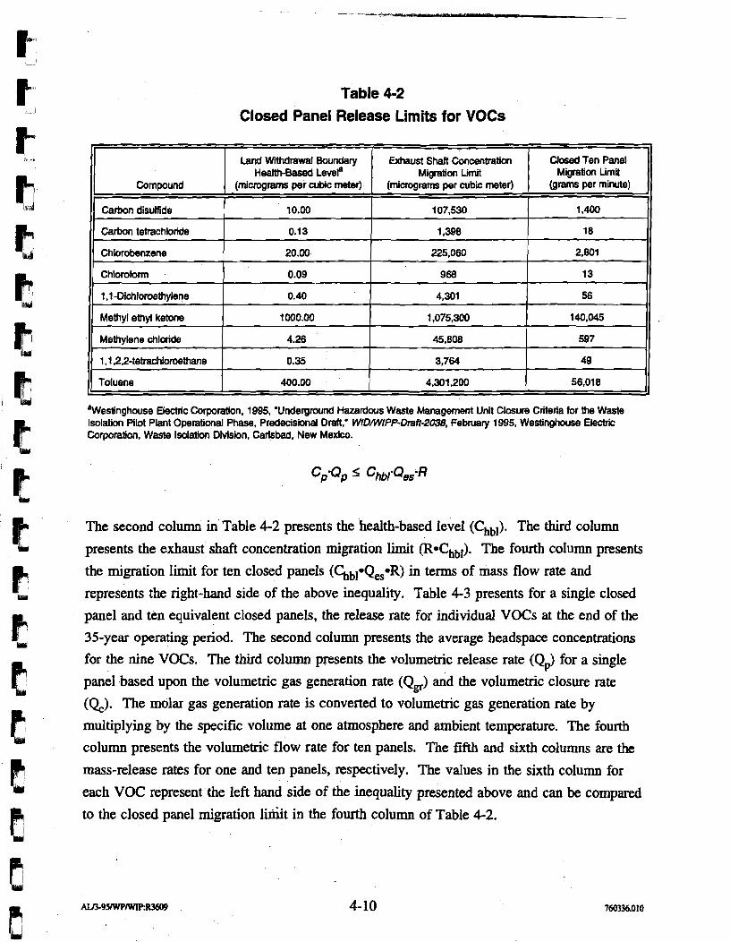
Table 4-2 Closed Panel Release Limits for VOCs
%Vestinghouse Electric Corporation. 1995, 'Underground Hazardous Waste Management Unit Closure CriterZa for the Waste Isolation Pilot Plant Operational Phase, Predecisional Draft,' WIDMPP-Draft-2038, February 1995, Westinghouse Electric Corporation, Waste Isolation Division, Carlsbad, New Mexico.
The second column in Table 4-2 presents the health-based level (Chbl). The third column
presents the exhaust shaft concentration migration limit (Rochbl). The fourth column presents
the migration limit for ten closed panels (Chbl*QeseR) in terms of mass flow rate and
represents the right-hand side of the above inequality. Table 4-3 presents for a single closed
panel and ten equivalent closed panels, the release rate for individual VOCs at the end of the
35-year operating period. The second column presents the average headspace concentrations
for the nine VOCs. The third column presents the volumetric release rate (Q& for a single
panel based upon the volumetric gas generation rate (Qs) and the volumetric closure rate
(Q). The molar gas generation rate is converted to volumetric gas generation rate by
multiplying by the specific volume at one atmosphere and ambient temperature. The fourth
column presents the volumetric flow rate for ten panels. The fifth and sixth columns are the
mass-release rates for one and ten panels, respectively. The values in the sixth column for
Compound
Carbon disuffide
Carbon tetrachloride
Chlorobenzene
Chloroform
1 .l-Dichloroethylene
Methyl ethyl ketone
Methylene chloride
1.1 22-tetrachl0r08thane
Toluene
each VOC represent the left hand side of the inequality presented above and can be compared
to the closed panel migration liriiit in the fourth column of Table 4-2.
Land WMmwal Boundary ~ealth-~ased ever
(micrograms per cubic meter)
10.00
0.13
20.00
0.09
0.40
1000.00
4.26
0.35
400.00
Exhaust Shaft Concentration Migration Limit
(micrograms per cubic meter)
107,530
1,398
225,060
968
4,301
1,075,300
45,808
3,764
4,301,200
Closed Ten Panel Migration Liml
(grams per minute)
1,400
18
2,801
13
56
140,045
597
49
56,018
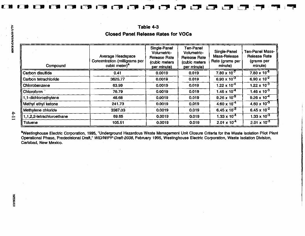
Table 4-3
Closed Panel Release Rates for VOCs
I I I I
Chloroform ' 76.79 0.001 9 0.01 9 1 1.46x10‘4 1 1 . 4 6 ~ 1 0 " 1)
Compound
Carbon disulfide
Carbon tetrachloride
Average Headspace Concentration (milligrams per
cubic meter)a
0.41
3625.77
1 ,1 -dichloroethylene
Methyl ethyl ketone
Methylene chloride
'westinghouse Electric Corporation, 1995, "Underground Hazardous Waste Management Unit Closure Criteria for the Waste Isolation Pilot Plant Operational Phase, Predecisional Draft," WIDAWPP-Draft-2038, February 1995, Westinghouse Electric Corporation, Waste Isolation Division, Carlsbad, New Mexico.
1 ,1 ,2,2-tetrachloroethane
Toluene
Single-Panel Volumetric-
Release Rate (cubic meters per minute)
0.001 9
0.0019
48.68
241.73
3387.03
69.65
105.51
Ten-Panel Volumetric-
Release Rate (cubic meters per minute)
0.01 9
0.01 9
0.001 9
0.0019
0.001 9
0.001 9
0.001 9
Single-Panel Mass-Re1eaSe
Rate (grams per minute)
7.80 x 10 '~
6.90 l o4
0.01 9
0.01 9
0.01 9
Ten-Panel Mass- Release Rate
(grams per minute)
7.80 x 10.'
6.90 x
0.01 9
0.01 9
9.26 x 4.60 x 10'~
6.45 x lv3
9.26 x
4.60 x 10 '~
6.45 x lom2 1.33 x 1v4
2.01 10 ‘~ 2.01 x 1 0 ' ~
For the WIPP 16-section land withdrawal boundary, the VOC concentrations are reduced
substantially in the atmosphere. The above analysis shows that the concentration at the land
withdrawal boundary would be approximately 4 orders of magnitude less than the
concentration at the exhaust shaft. The predicted VOC mass flow rates due to unrestricted
flow suffice to comply with the closed ten-panel migration limit based upon the health-based
levels at the land withdrawal boundary over the operational life of the repository.
4.3 Structural Safety Barrier In Case of Methane Explosion Federal regulations governing the barricading of abandoned salt mines evolved from concerns
over the natural occurrence of methane. D'Appolonia (1983) documented natural gas
occurrences in salt for the high-level waste program. These gas occurrences were described ,
for dome salt, Permian Basin salt, and Paradox Basin salt, which at the time were being
considered as candidate sites for a high-level nuclear waste disposal site. D'Appolonia
concluded at the time that the hazards for bedded salt in the Permian Basin are less than for
dome salt and suggested that underground continuous mining experience at WIPP is pertinent
to assessing the significance of gas occurrences, classification of the underground workings,
and the development of special mining procedures, such as reduced spacing between
crosscuts, increased ventilation, or the operation of permissible equipment.
Since that time, the experience gained at WIPP demonstrates that, while small natural gas
occurrences exist, their significance is within the classification of Category IV for natural gas
under the Mine Safety and Health Administration (MSHA) and that no special procedures are warranted for panel closure system design.
While no specific requirements for barricading closed waste areas exist under MSHA, the
intent of the regulations in constructing barricades of "substantial construction" is to safely
isolate these abandoned areas from the active workings. The following analysis examines the
issue of methane gas generation from TRU waste and the potential consequence in abandoned
areas.
The principal concern regarding whether gas generation would result in hazardous working
conditions is the occurrence of an explosive mixture of methane and an ignition source, which
would result in either a detonation or deflagration.
In Section 4.1, the gas-generation rate was discussed, and the current information on the
project suggests that gas generation, due to microbial degradation, might equal 0.1 moles per
drum per year. It is difficult to estimate the degree to which methane would be produced in
comparison to nonexplosive gases (e.g., carbon dioxide). However, an upper bound of the
amount of methane produced can be established at 70 percent of the total microbial gas
generation, even under anaerobic conditions. Thus, it is possible to bound the amount of
methane produced for a given gas-generation rate, including the volume occupied by the gas.
The percent volume concentration can be compared to the explosive limits for methane that
are established in Figure 4-2.
If the composition of the air in the closed panel is 18 percent oxygen, the explosive range is
from about 5 to 15 percent methane by volume. Above 15 percent methane, the atmosphere
in an abandoned panel would be "fuel rich" and would not be capable of sustaining an
explosion. With a reduction in the amount of oxygen available, the explosive range narrows,
and the potential is nonexistent below a 12 percent oxygen composition.
The potential for an explosive source of methane can be evaluated with a simple model under
the following assumptions:
The gas-generation rate varies from 0.01 to 1.0 moles per drum per year.
The composition of the gas is 70 percent methane, with nonexplosive gases comprising the remaining gas.
No consideration is given to the reduction of oxygen that might accompany gas generation.
Figure 4-3 presents the results of the analysis and shows that for a reasonable gas-generation
rate, a potential explosive mixture could conceivably exist after a period of about 20 years.
For a higher gas-generation rate, the panel atmosphere would go "fuel rich" in a shorter
period of time (i.e., within several years). For the case of a lower gas-generation rate, the
panel atmosphere would remain nonexplosive over the entire duration of underground
operations.
Potential ignition sources can be identified for methane explosions and underground fires.
These include spontaneous combustion, static electricity, and sparks from falling rock salt. It
should be noted that with surface-storage of TRU waste, there have only been rare instances
of drums spontaneously igniting (Westinghouse, 1987). In addition, the Waste Acceptauce
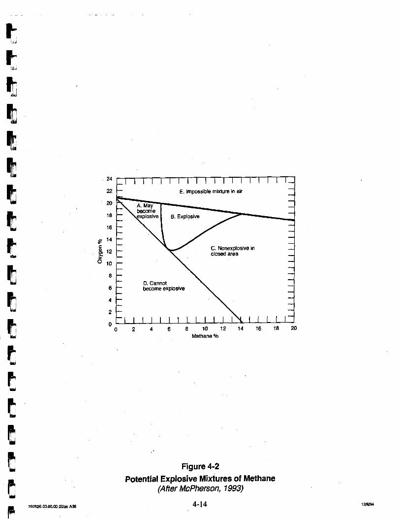
- -
- - - - - - C. Nonexplosive in -
closed area - - - - - - - -
D. Cannot - - become explosive - - - -
~ ~ ‘ I I I I I I I I I I I I I I I I I I I , -
Methane O h
22
Figure 4-2 Potential Explosive Mixtures of Methane
(After McPherson, 1993)
- E. Impossible mixture in air - -
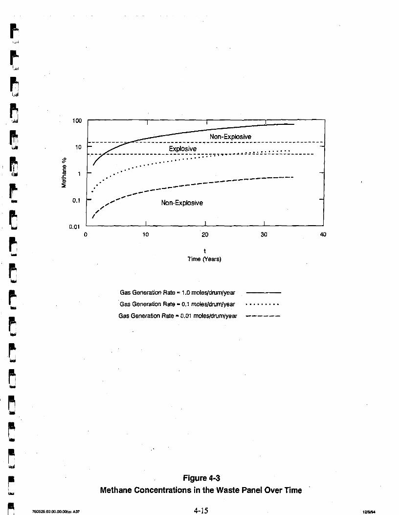
_cI____--------
d--
-c--- -4-
4@- - // - / / Non-Explosive
/' I I I
t Time (Years)
Gas Generation Rate = 1.0 moles/drum/year
Gas Generation Rate = 0.1 moles/drum/year . . . . Gas Generation Rate = 0.01 rnoles/drurn/year -- ----
Figure 4-3 Methane Concentrations in the Waste Panel Over Time
Criteria (DOE, 1991) for WIPP limit the pyrophoric radionuclide content to 1 percent by
weight. Other pyrophorics are to be processed or rendered safe.
These considerations suggest that ignition is an unlikely event and is not anticipated.
However, because the current experience gained with TRU waste involves storage at the
surface, it is unknown to what extent surface storage serves as an accurate analog for
spontaneous ignition for underground storage in a confined space. In contrast, design and
construction methods are available for bulkheads to withstand underground explosions, as
proven by experience on the Strategic Petroleum Reserve project (D'Appolonia, 1978). The
static and dynamic loadings on the panel closure barrier can be evaluated through structural
analysis, and components sized accordingly to withstand a detonation with no adverse
consequence.
4.4 Restricting Flow of Gases Out of a Panel Another method to prevent the migration of VOCs is to construct barriers that restrict flow.
The panel barriers in the two entries could reduce the volumetric flow equivalent (due to
creep closure and gas generation) by utilizing the compressive storage in the void space of the
panel. The panel barriers could restrict transient flow over the operational period to an
effective gas-generation rate substantially less than the steady state flow rate of about
1,000 m3 per year. The subsequent discussion of the gas flow model illustrates this design
principle.
A gas-flow model was developed to assess the performance of panel barriers in the restriction
of flow and to further refine the design requirement for gas flow through barriers. In these
calculations, the gases generated in the waste emplacement area would be stored in part by
the compressive storage of the void space within the panel and would in part flow out of the
waste emplacement areas into the main return air. The following assumptions are made in
the restricted gas-flow model:
The gases (including VOCs) within the void space obey the Ideal Gas Law (see Appendix A). The gases are generated at a rate of 0.1 moles per drum per year and are stored by an increase in gas pressure. The rate of pressure buildup is so gradual that it occurs at constant temperature.
Volumetric reductidn due to creep reduces the void space at a rate of 28,250 f$ (800 m3) per year and results in pressurization.
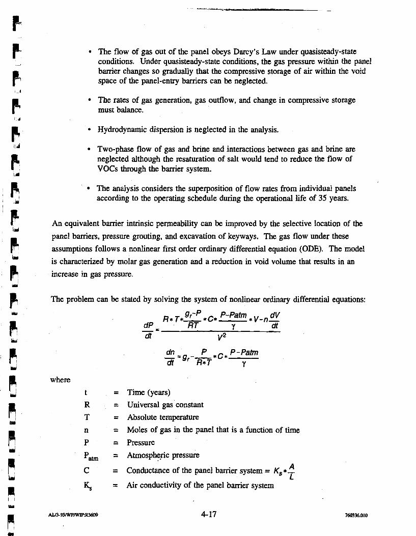
The flow of gas out of the panel obeys Darcy's Law under quasisteady-state conditions. Under quasisteady-state conditions, the gas pressure within the panel barrier changes so gradually that the compressive storage of air within the void space of the panel-entry barriers can be neglected.
The rates of gas generation, gas outflow, and change in compressive storage must balance.
Hydrodynamic dispersion is neglected in the analysis.
Two-phase flow of gas and brine and interactions between gas and brine are neglected although the resaturation of salt would tend to reduce the flow of VOCs through the barrier system.
The analysis considers the superposition of flow rates from individual panels according to the operating schedule during the operational life of 35 years.
An equivalent barrier intrinsic permeability can be improved by the selective location of the
panel barriers, pressure grouting, and excavation of keyways. The gas flow under these
assumptions follows a nonlinear first order ordinary differential equation (ODE). The model
is characterized by molar gas generation and a reduction in void volume that results in an
increase in gas pressure.
The problem can be stated by solving the system of nonlinear ordinary differential equations:
gr-P P- Patm R* T*- *C* * V-n- dV dP - -- RT Y dt dt v2
dn P - =gr--*c* P - Patm dl R* T Y
where
Time (years) Universal gas constant
Absolute temperature
Moles of gas in the panel that is a function of time
Pressure
Atrnosphe.ric pressure A Conductance of the panel barrier system = K, *- L
Air conductivity of the panel barrier system
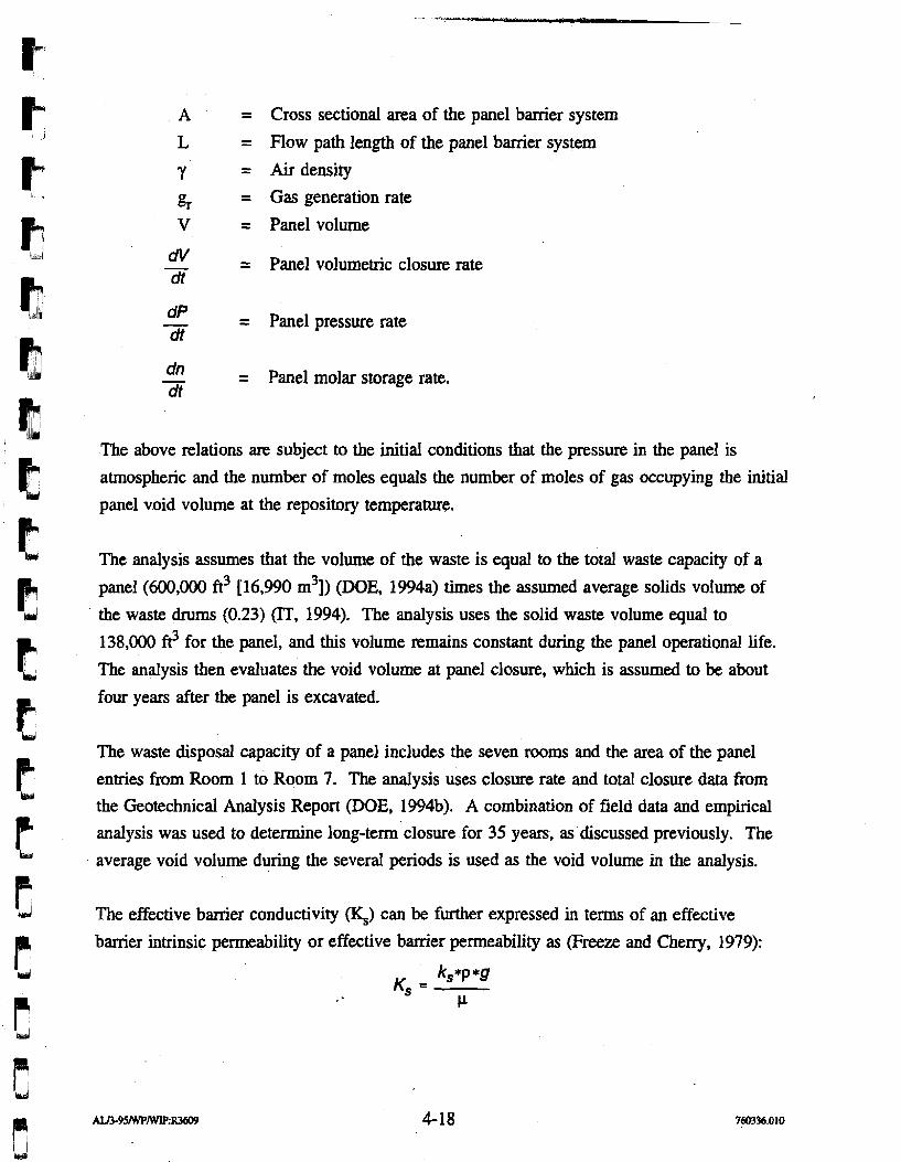
A = Cross sectional area of the panel barrier system
L = Flow path length of the panel barrier system
Y = Air density
gr = Gas generation rate V = Panel volume
dV - = Panel volumetric closure rate dt
dP - = Panel pressure rate dt
dn - = Panel molar storage rate. dt
The above relations are subject to the initial conditions that the pressure in the panel is
atmospheric and the number of moles equals the number of moles of gas occupying the initial
panel void volume at the repository temperature.
The analysis assumes that the volume of the waste is equal to the total waste capacity of a
panel (600,000 ft3 [16,990 m3]) (DOE, 1994a) times the assumed average solids volume of
the waste drums (0.23) (IT, 1994). The analysis uses the solid waste volume equal to
138,000 ft3 for the panel, and this volume remains constant during the panel operational life.
The analysis then evaluates the void volume at panel closure, which is assumed to be about
four years after the panel is excavated.
The waste disposal capacity of a panel includes the seven rooms and the area of the panel
enties from Room 1 to Room 7. The analysis uses closure rate and total closure data from
the Geotechnical Analysis Report (DOE, 1994b). A combination of field data and empirical
analysis was used to determine long-term closure for 35 years, as discussed previously. The
average void volume during the several periods is used as the void volume in the analysis.
The effective barrier conductivity (q) can be further expressed in terms of an effective
barrier intrinsic permeability or effective barrier permeability as (Freeze and Cherry, 1979):
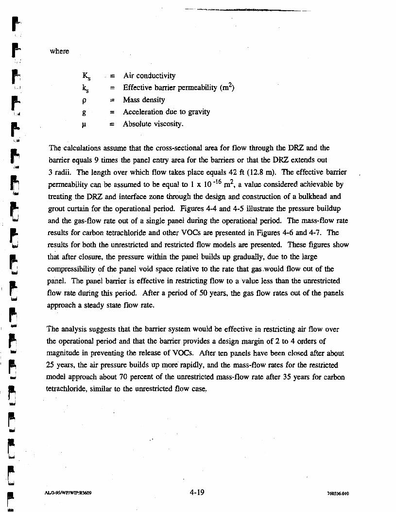
where
~ = Air conductivity
ks = Effective banier permeability (m2)
P = Mass density
g = Acceleration due to gravity
P = Absolute viscosity.
The calculations assume that the cross-sectional area for flow through the DRZ and the
barrier equals 9 times the panel entry area for the barriers or that the DRZ extends out
3 radii. The length over which flow takes place equals 42 ft (12.8 m). The effective barrier ,
permeability can be assumed to be equal to 1 x 10 -I6 m2, a value considered achievable by
treating the DRZ and interface zone through the design and construction of a bulkhead and
grout curtain for the operational period. Figures 4-4 and 4-5 illustrate the pressure buildup
and the gas-flow rate out of a single panel during the operational period. The mass-flow rate
results for carbon tetrachloride and other VOCs are presented in Figures 4-6 and 4-7. The
results for both the unrestricted and restricted flow models are presented. These figures show
that after closure, the pressure within the panel builds up gradually, due to the large
compressibility of the panel void space relative to the rate that gas.would flow out of the
panel. The panel barrier is effective in restricting flow to a value less than the unrestricted
flow rate during this period. After a period of 50 years, the gas flow rates out of the panels
approach a steady state flow rate.
The analysis suggests that the barrier system would be effective in restricting air flow over
the operational period and that the banier provides a design margin of 2 to 4 orders of
magnitude in preventing the release of VOCs. After ten panels have been closed after about
25 years, the air pressure builds up more rapidly, and the mass-flow rates for the restricted
model approach about 70 percent of the unrestricted mass-flow rate after 35 years for carbon
tetrachloride, similar to the unrestricted flow case.
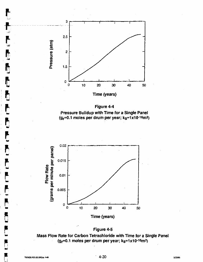
Time (years)
Figure 4-4 Pressure Buildup with Time for a Single Panel
(gr=O.l moles per drum per year; ks=i xi 0-16m2)
Time (years)
l! Figure 4-5 iuj Mass Flow Rate for Carbon Tetrachloride with Time for a Single Panel
P (gr=O.l moles per drum per year; ks=ixl0-~6m2)
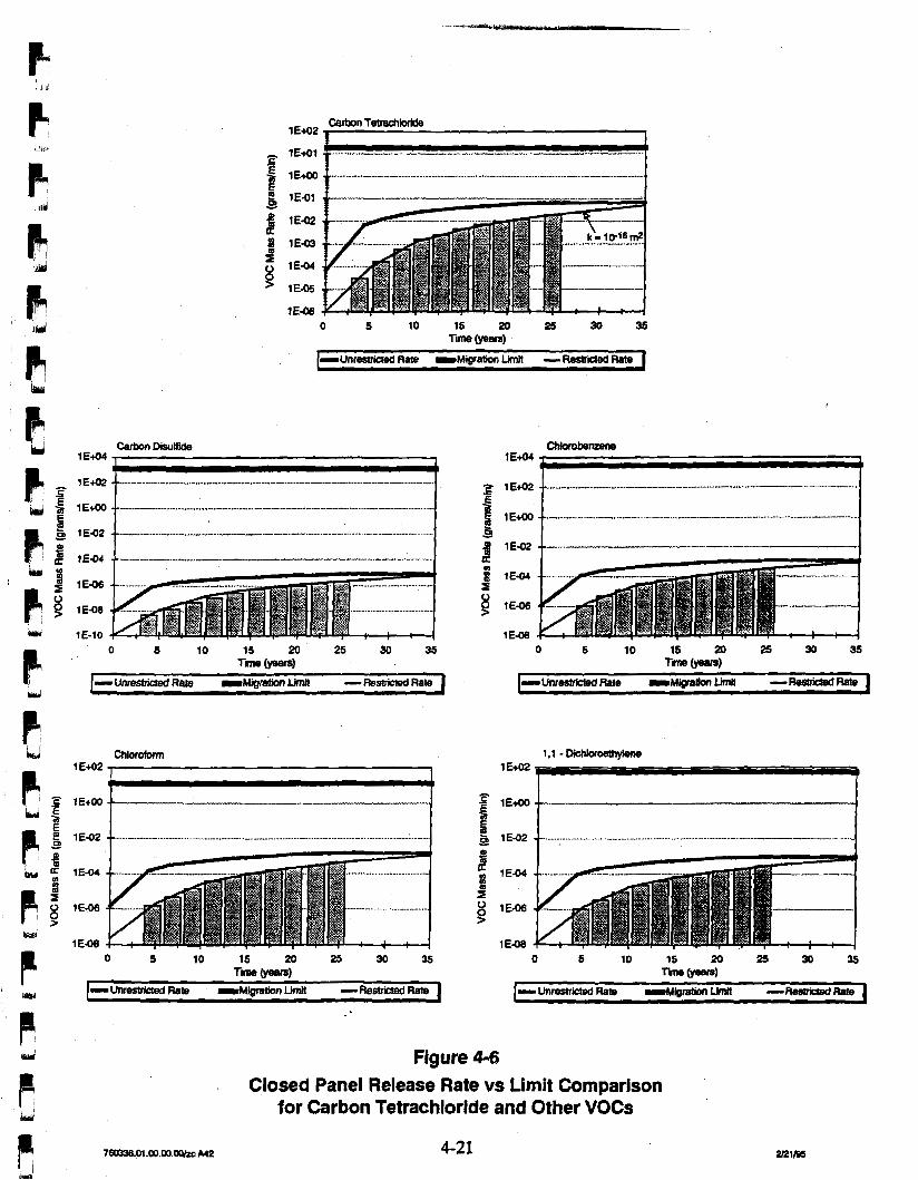
-Unresmcred Rate M i r e l i o n Limi! - Restrided Rate
1 - UnmariCted Rate M i g r a t i o n L;mff - Restricled Rate *u
0 5 10 15 20 25 30 35 T i (years)
t-~nrestri*edRa!e -Miprelim LimB -ResbibsdRete I
Figure 4-6
Closed Panel Release Rate vs Limit Comparison for Carbon Tetrachloride and Other VOCs
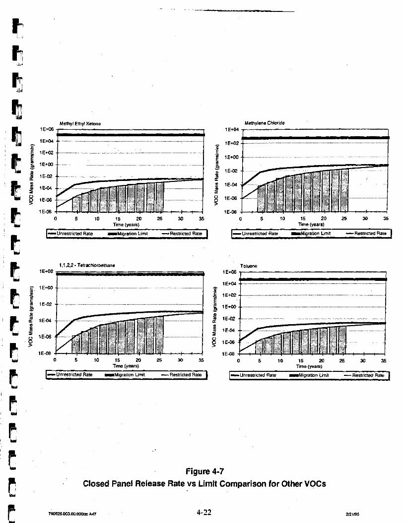
Melhyl Ethyl Ketone 1 E+06 7 I
0 5 10 15 20 25 30 35 T i e (years)
Methylene Chloride 1 E+04 , 1
1,1.2,2 - Tetrachloroethane
W
0 5 10 15 20 25 30 35 l ime (vears)
1-~nrestricted FIaG M i o r a t i o n Lim~t -Restricted Rate I 1- Unrestricted Rate -Mioralion timil -Restricted Rate I
0 5 10 15 20 25 30 35 Time (vearsl
1- Unrestricted Rate M a r a t i o n Limit -Restricted m ate 1
Toluene 1 E+06
1 E-08 0 5 10 15 20 25 30 35
T i e (years)
I-~nrestricted Rate ~ M i o r a t i o n Limit -Restricted Rate 1
Figure 4-7 Closed Panel Release Rate vs Limit Comparison for Other VOCs
5.0 Conceptual Design of a Panel Closure System
This chapter presents a description of the conceptual design of the recommended panel
closure system. In Section 5.1, the current design criteria and requirements for the RCRA
pennit are summarized. In addition, panel closure system performance uncertainties are
summarized, and possible options are evaluated. In Section 5.2, a conceptual design for a
panel is selected, and a preliminary performance specification for the operational period is
provided to show compliance with the no-migration standards for the release of VOCs.
Available technologies are reviewed for application to the conceptual design. Certain design
features and aspects of the design requirement field studies are presented.
5.1 Summary of Design Requirements The initial concentration of VOCs, the volumetric closure due to creep, the gas-generation
rate, and the flow properties of the barrier determine the performance of the panel closure
system in relation to the no-migration standards. The analysis for panel closure systems
presented in the previous chapter show that the performance goal for the mass-flow rate of
VOCs for the panel closure system is met by a design margin of 2 orders of magnitude for
carbon tetrachloride by reducing the VOC concentration from the ventilation system and from
atmospheric dispersion. If consideration is given to the use of available technology for 16 2 grouting, the restriction of flow to an estimated intrinsic permeability of 10- m would be
effective during the early stages of repository development in providing a design margin for
carbon tetrachloride of 2 to 4 orders of magnitude.
Performance of the panel closure system would depend on a number of factors (presented
above). The molar gas-generation rate depends on many factors specific to the waste form
that would be aggregated for the entire panel. It also depends on different processes, such as
anoxic corrosion, radiolysis, and microbial degradation. Current estimates of the molar gas-
generation rate range from 0.01 moles per drum per year to 1.06 moles per drum per year. A
baseline gas-generation rate of 0.1 moles/drum.year is assumed, based on a contribution of
0.1 moles/drum/year from microbial degradation and no contribution from anoxic corrosion.
The analysis of VOC mass flow rates as determined from both the restricted and unrestricted
flow models established that the system would be in substantial compliance for the
operational period.
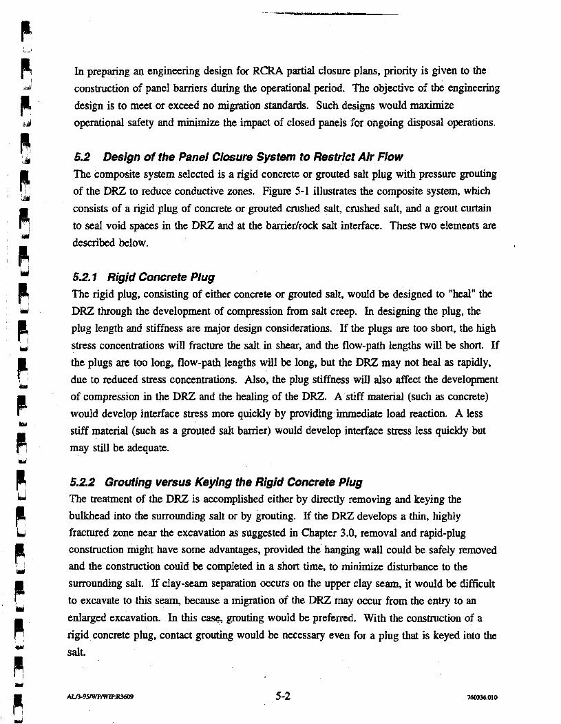
In preparing an engineering design for RCRA partial closure plans, priority is given to the
construction of panel barriers during the operational period. The objective of the engineering
design is to meet or exceed no migration standards. Such designs would maximize
operational safety and minimize the impact of closed panels for ongoing disposal operations.
5.2 Design of the Panel Closure System to Restrict Air Flow The composite system selected is a rigid concrete or grouted salt plug with pressure grouting
of the DRZ to reduce conductive zones. Figure 5-1 illustrates the composite system, which
consists of a rigid plug of concrete or grouted crushed salt, crushed salt, and a grout curtain
to seal void spaces in the DRZ and at the bamer/rock salt interface. These two elements are
described below.
52.7 Rigid Concrete Plug The rigid plug, consisting of either concrete or grouted salt, would be designed to "heal" the
DRZ through the development of compression from salt creep. In designing the plug, the
plug length and stiffness are major design considerations. If the plugs are too short, the high
stress concentrations will fracture the salt in shear, and the flow-path lengths will be short. If
the plugs are too long, flow-path lengths will be long, but the DRZ may not heal as rapidly,
due to reduced stress concentrations. Also, the plug stiffness will also affect the development
of compression in the DRZ and the healing of the DRZ. A stiff material (such as concrete)
would develop interface stress more quickly by providing immediate load reaction. A less
stiff material (such as a grouted salt barrier) would develop interface stress less quickly but
may still be adequate.
5.2.2 Grouting versus Keying the Rigid Concrete Plug The treatment of the DRZ is accomplished either by directly removing and keying the
bulkhead into the surrounding salt or by grouting. If the DRZ develops a thin, highly
fractured zone near the excavation as suggested in Chapter 3.0, removal and rapid-plug
construction might have some advantages, provided the hanging wall could be safely removed
and the construction could be completed in a short time, to minimize disturbance to the
surrounding salt. If clay-seam separation occurs on the upper clay seam, it would be difficult
to excavate to this seam, because a migration of the DRZ may occur from the entry to an
enlarged excavation. In this case, grouting would be preferred. With the construction of a
rigid concrete plug, contact grouting would be necessary even for a plug that is keyed into the
salt.
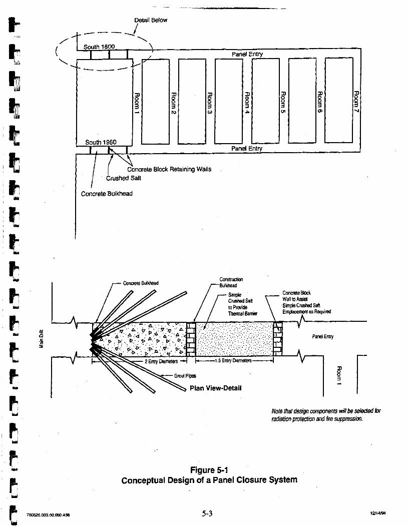
I /-- Concrete Bulkhead
Plan View-Detail
Note fhat design components will be seleded for radiation protection and fire suppression.
Figure 5-1 Conceptual Design of a Panel Closure System
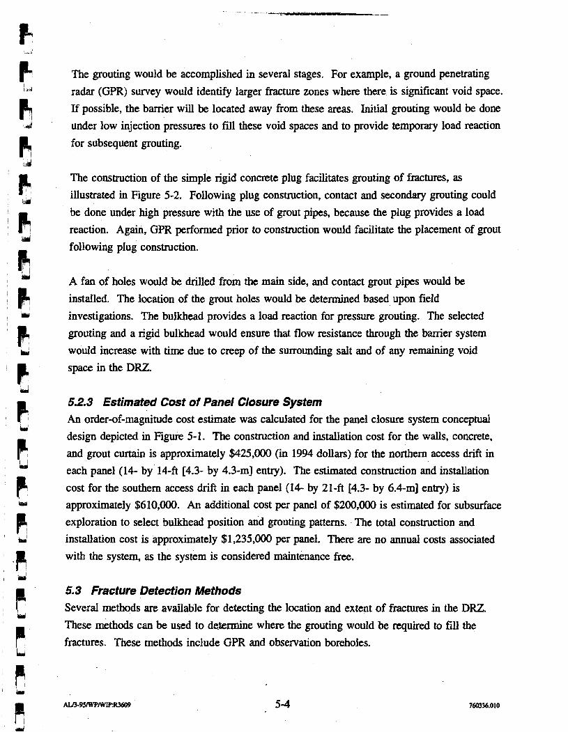
The grouting would be accomplished in several stages. For example, a ground penetrating
radar (GPR) survey would identify larger fracture zones where there is significant void space.
If possible, the barrier will be located away from these areas. Initial grouting would be done
under low injection pressures to fdl these void spaces and to provide temporary load reaction
for subsequent grouting.
The construction of the simple rigid concrete plug facilitates grouting of fractures, as
illustrated in Figure 5-2. Following plug construction, contact and secondary grouting could
be done under high pressure with the use of grout pipes, because the plug provides a load
reaction. Again, GPR performed prior to construction would facilitate the placement of grout
following plug construction.
A fan of holes would be drilled from the main side, and contact grout pipes would be
installed. The location of the grout holes would be determined based upon field
investigations. The bulkhead provides a load reaction for pressure grouting. The selected
grouting and a rigid bulkhead would ensure that flow resistance through the barrier system
would increase with time due to creep of the surrounding salt and of any remaining void
space in the DRZ.
5.2.3 Estimated Cost of Panel Closure System An order-of-magnitude cost estimate was calculated for the panel closure system conceptual
design depicted in Figure 5-1. The construction and installation cost for the walls, concrete,
and grout curtain is approximately $425,000 (in 1994 dollars) for the northern access drift in
each panel (14- by 1 4 4 r4.3- by 4.3-m] entry). The estimated construction and installation
cost for the southern access drift in each panel (14- by 2 1 4 [4.3- by 6.4-m] entry) is
approximately $610,000. An additional cost per panel of $200,000 is estimated for subsurface
exploration to select bulkhead position and grouting patterns. The total construction and
installation cost is approximately $1,235,000 per panel. There are no annual costs associated
with the system, as the system is considered maintenance free.
5.3 Fracture Detection Methods Several methods are available for detecting the location and extent of fractures in the DRZ. These methods can be used to determine where the grouting would be required to fill the
fractures. These methods include GPR and observation boreholes.
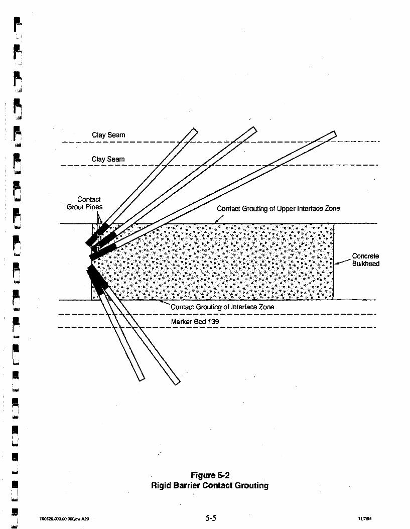
Figure 5-2 Rigid Barrier Contact Grouting
GPR is a nondestructive electromagnetic reflection technique that is sensitive to variations in
the dielectrical constant of rock salt. The use of GPR is a proven technology for detecting
free-flow fracture zones within the WIPP underground and will have practical value in the
design of panel barriers (IT, 1993). GPR will be used to detect shallow fracturing of the
halite around the panel entries and determine the position of fractures relative to the surface
of the back and floor of the panel entries. GPR surveys perpendicular to the long axis of the
drift would be conducted at 2- to 4-ft (0.6- to 1.2-m) intervals along the roof and floor of the
entry drifts. Additionally, axial surveys along the length of the panel entries for both the roof
and floor should be conducted.
GPR surveys would show the location and depth of fractures in the halite surrounding the ,
panel entries. GPR surveys would also provide an indication of the overall amount of
fracturing that has occurred in the panel entries since their excavation. Radar surveys may
indicate the extent to which fractures are interconnected. If fracturing is severe, the GPR
surveys would indicate areas where fractured material may need to be removed to reach
nonfractured rock necessary for barrier emplacement. These GPR surveys will provide
confidence for the effective placement of grout in fracture zones or identify shallow fracture
zones within the DRZ for removal.
For future waste panels, GPR could be used to monitor fracture development. Radar surveys
could be conducted shortly after excavation to provide a baseline with which to compare
future radar surveys. GPR could then be used periodically to monitor the development of
brittle deformation occumng in the new panel entry.
Observation boreholes are drilled into the roof or floor of an excavation, and are used for
observation of fractures and bed separation. Observations can be made in the boreholes
through complex methods, such as the use of small video cameras, or by simple methods,
such as the use of a scratch rod. A scratch rod is run to the end of the observation borehole and then pulled out while scratching the side of the hole.
Borehole inspections of fracturing and bed separation have proven to be the most successful
method for determining the condition of the rock immediately surrounding excavations at
WIPP. Fracture logging of open.boreholes has been done on an informal basis since the first
holes were drilled at the facility horizon in 1983 (Francke and Terrill, 1993). The Excavation
Effects Program (EEP) was initiated in 1986 after the discovery of a large k t u r e system in
SPDV Test Room 3. The purpose of the EEP is to study fractures that develop a result of
underground excavation at the WlPP and to provide consistent documentation and monitoring
of those fractures.
5.4 Structural Design of the Panel Closure System The conceptual design of the panel closure system includes a simple backfill of crushed salt
and a concrete bulkhead designed to provide strength and deformational serviceability during
the operational period. The bulkhead length is selected as approximately twice the maximum
panel entry width to assure that uniform compression develops over a substantial portion of
the structure and that end-shear loading that might result in fracturing of salt into the back is
reduced over a portion of the plug. The crushed salt backfill is provided to reduce the
potential for fracturing at one end of the bulkhead and to provide a pressure and thermal
barrier if a methane explosion should occur.
A series of simple analyses are provided in Appendix C for the selection of properties in
bulkhead construction. These analyses are summarized as follows:
A standard creep analysis of a 1-degree-of-freedom model shows that radial and tangential plug stresses on the concrete bulkhead in contact with the surrounding salt formation would develop in several years. The anticipated state of biaxial compression would require plain concrete with an unconfined compressive strength of 3,000 psi.
A standard dynamic analysis of a 1-degree-of-freedom model was performed to assess loadings on the plug for an unanticipated methane detonation. The analysis shows that the increase in stress is minimal, and given that lateral load resistance develops on the plug due to interface stress development, the bulkhead has ample rigidity and compressive strength to remain stable for short-term dynamic loadings.
A standard thermal stress analysis was performed to assess increased thermal stress on the plug over the longer term. The results of the analysis show that with a 200-degree temperature gradient across the barrier from an unanticipated methane detonation, the increase in thermal stress might result in some cracking. The bulkhead should remain rigid and have compressive strength to remain stable for longer-term thermal loadings, because thermal stress is self relieving, and the bulkhead is in an overall state of compression.
These preliminary analyses are in-agreement with analyses performed by Slezak (1990).
Slezak considered the case of a detonation following the emplacement of a composite panel
seal and analyzed for short-duration loads. He considered a "worst-case mix" of hydrogen,
methane, and oxygen for conversion to C02 and water. He examined the headspace above
the waste stack and concluded that it might be capable of propagating a methane-based
"detonation."
The calculations performed by Slezak (1990) using the Gordon-McBride code show that a
peak pressure of approximately 800 psi would be applied to the front face of the barrier and
would immediately begin to decay in a linear fashion, to approximately 120 psi at
0.35 seconds after impact. The peak compressive pressure on the back face of the barrier
component was estimated to be only a few psi. The pressure-decay rate on the front face at longer times is somewhat uncertain, because it depends on the thermal coupling of headspace
gases to surrounding rock and waste/backfi. Because the high pressures decay so quickly , and the grout plug is so massive (and hence would respond slowly), dynamic calculations
show the effective pressures are not sustained over a long time.
The estimated consequences of the assumed detonation were found to be negligible, because
of the massive character of the grout component of the composite seal (assumed to be 30 ft [9.2 m] in length). It was estimated that there might be some fracturing of salt to a depth of
several feet but that the surrounding salt would dissipate the assumed shock wave.
5.5 Available Technologies for Bulkhead Installation and Grouting Fernandez and Richardson (1994) assess the availability of technologies needed for sealing
the potential high-level waste repository at Yucca Mountain. They evaluated technologies for
three basic groups, including backfill (general fill and graded fill), bulkhead, and grout curtains. They reviewed the literature, selecting many case histories from the mining, civil,
and defense industries; reviewed the case histories for application; and assessed the technologies for deficiencies. Tbeir conclusions were that technologies exist for the analysis,
design, and placement of sealing components consisting of backfill, bulkheads, and grout
curtains. Deficiencies exist in assessing the long-term performance of sealing components,
and in the placement of components in a high-temperature environment.
In applying this technology assessment to the design of the panel barrier system for the WPP during the operational period, neither the long-term perfonnance of the panel barriers and
their durability nor sustained elevated temperatures are an issue. Cement hydration
temperatures may be of a concern and may necessitate special construction procedures, such
as cisculation of water through the bukhead to reduce hydratioa temperatures or use of ice or
chilled water in batching operations. In conclusion, technologies are available for emplacing
bulkheads, backfill, and grout curtains.
A possible construction sequence for the construction of a rigid concrete plug is illustrated in
Figure 5-3. The bulkhead would first be formed. Forms could be built in the usual manner
following site preparation.
Two methods are available for handling of a salt saturated concrete: (1) batching the concrete
on the surface and delivering it to the bulkhead site and (2) transporting the concrete
components underground and mixing them at the site. A surface batch-plant location enables
better quality control at the plant but requires long-distance transportation. Concrete will be , vibrated when placed.
An alternate and very effective method for constructing a rigid underground bulkhead uses
grouted concrete. Grouted concrete, also known as Colcrete, Prepakt, and Preplaced
Aggregate Concrete, consists of crushed course salt aggregate (greater than 2 inches [5 cm])
preplaced in the bulkhead location and then grouted in place with a salt-saturated cement and
sand mixture (Fernandez and Richardson, 1994). This method of concrete bulkhead
construction has some advantages over cast-in-place concrete. Because the aggregate is not
premixed in the concrete, the volume of grout is much less than the volume of the mixed
concrete. This smaller volume is easier to handle and can be pumped long distances. The grouted concrete also makes a better contact with the hanging wall, and preplaced aggregate
tends to interlock mechanically and provides a better resistance to shear.
Contact and secondary grouting after rigid concrete plug emplacement would require drilling
equipment, circulation equipment, and hole fixtures. The GPR surveys and field
investigations would determine the hole pattern and the placement of grout in fractured zones
near the rigid concrete plug. Diamond-core drilling would reduce the probability of fracture
zones becoming clogged with fine cuttings (Fernandez and Richardson, 1994). Diamond core
drilling would also allow core recovery for quality control evaluation purposes.
Mixing equipment would include mixers and agitators and circulating equipment would
include pumps, circulation lines,.and hole fixtures. Figure 5-4 illustrates typical grouting
equipment. High-speed colloidal mixers are recommended for cement grouting, because they
improve the penetrating characteristics of the grout by mechanically separating clumps of
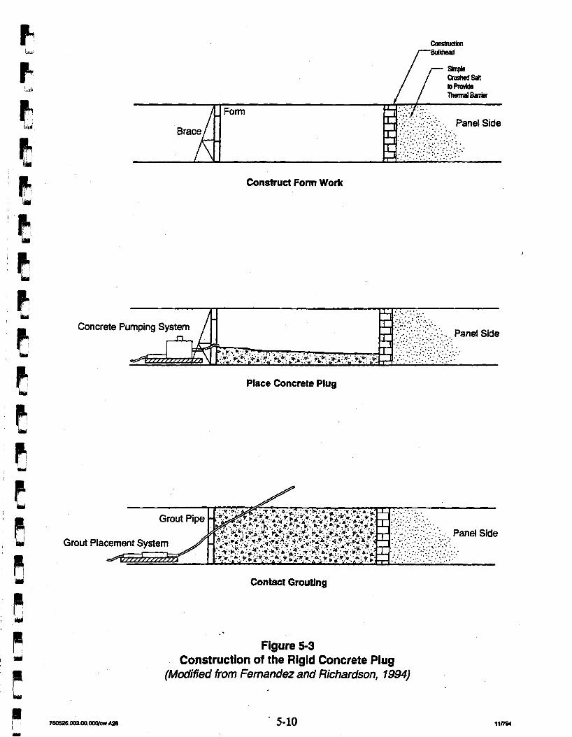
.. . . ... . .,. . . .. Panel Side
Construct Form Work
Concrete Pumping S
Place Concrete Plug
Grout
Contact Grwtlng
Figure 53 Construction of the Rigid Concrete Plug
(Modified from Femandez and Richardson, 1994)
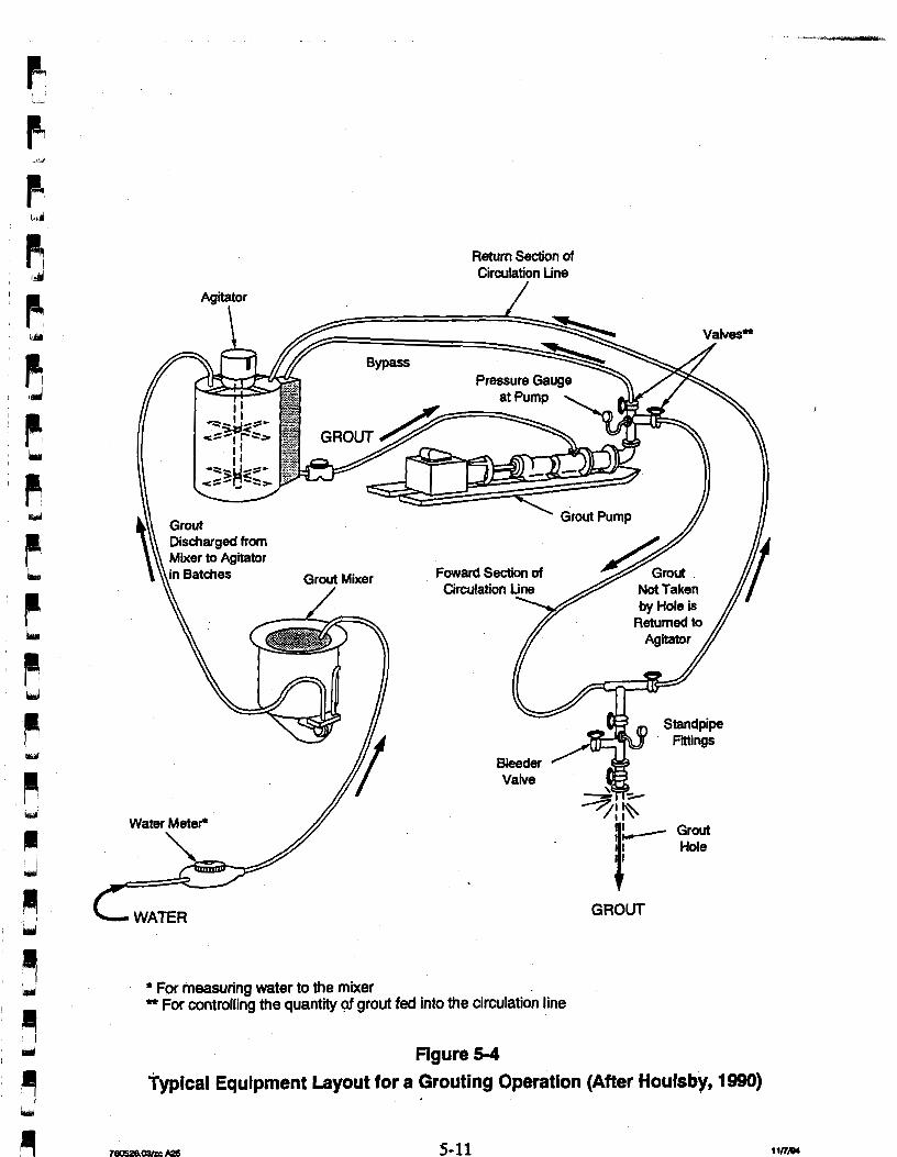
Agitator
Return Section of Circulation Line
/
C GROUT
For measuring water to the mixer * For controlling the quantity @ grout fed into the circulation line
Figure 5-4
Typical Equipment Layout for a Grouting Operation (After Houlsby, 1990)
particles and completely wetting individual particles. Agitators are necessary to prevent
settling of the grout after mixing during temporary storage prior to injection.
For grout placement, Bruce (1989) reports on a technological innovation using a multiple
packer sleeved pipe for grouting in fractured rock (Figure 5-5). A tube with multiple
permanent packers is inserted into the hole, and the casing is withdrawn to allow the precise
placement of grout. The grouted zone can then be pressure tested. Tertiary, quaternary, and split-spacing holes may be required until the ground is tight. Contact grouting at the interface
of the rigid concrete plug and the surrounding rock could be achieved using the multiple
sleeved pipe.
To optimize the potential grouting of fractures and the interface zone to achieve low
conductivity for a panel, subsurface exploration at the barrier location will be required. A
recent grouting investigation performed in Room L3 of the WIPP underground shows that
transmissivities in the DRZ were reduced by as much as 4 orders of magnitude in the grouted
test area as compared to the DRZ adjacent to the test zone. Drilling was done with custom-
designed (by SNUNM) , compressed-air, vacuum-assisted, reverse-circulation diamond-drill
equipment. A micro-fine cement-based grout was pumped under high pressure into the DRZ. A concrete restraining slab and jacks were required to facilitate the pressure grouting
operation.
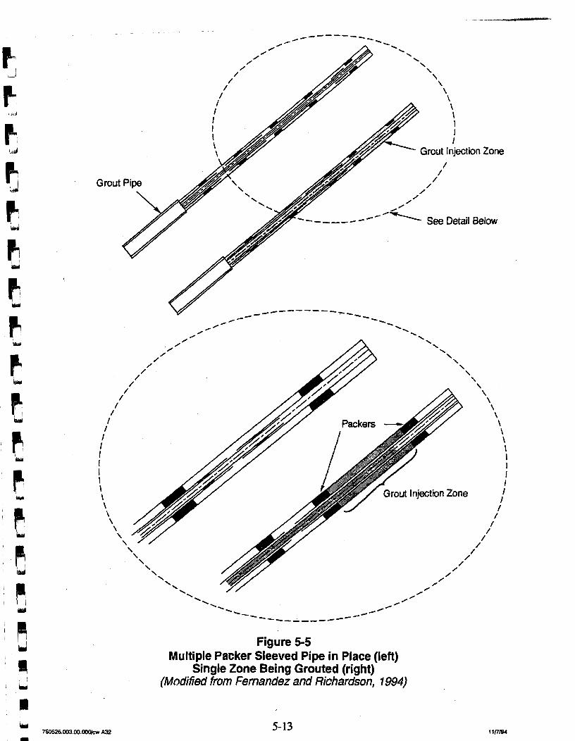
Figure 5-5 Multiple Packer Sleeved Pipe in Place (left)
Single Zone Being Grouted (right) (Modfied from Fernandez and Richardson, 1994)
6.0 Conclusions and Recommendations
This chapter presents conclusions and recommendations for future design activities for the
panel closure system. Section 6.1 presents the results of the literature review. Section 6.2
presents conclusions for the performance criteria and the conceptual design. Section 6.3
presents recommendation for future detailed &sign studies.
6.1 Results of the Literature Review The results of the literature review were presented to summarize previous drift seal designs
and their application to a WIPP panel barrier. A literature review was conducted of panel
barrier concepts and field testing as developed by the ONWI high-level waste program, the
SNL/NM WIPP repository sealing program, and other panel barrier concepts. In addition,
information on the DRZ (extent and permeability enhancement), potential fracturing of
MB 139, and interface zone properties directly relevant to developing a conceptual design for
panel closure systems is presented.
Panel bulkheads were considered in the &sign of repositories for the Permian Basin and the
Paradox Basin (Kelsall et al., 1982; 1983; 1985). Those sites were at the time being
evaluated for the disposal of high level waste. Panel bulkheads were proposed to isolate
those panels in which waste emplacement and b a c k f . g operations were completed from the
main passageways. In the conceptual design, panel bulkheads are built from preformed salt
bricks or concrete. Construction would first involve excavating a continuous keyway a few
feet around the complete drift perimeter to remove blast-damaged, stress-relieved, or
weathered salt. The depth of the keyway should be determined on a site-specific basis. The
keyway should extend in the roof and floor to intercept any clay seams that could form a
preferred pathway around the banier. Salt bricks would be stacked w i t h the bulkhead area, and any spaces between the bricks would be packed with crushed salt.
The SNWNM WIPP repository sealing program developed concepts for panel barriers
(Hansen et al., 1993). A design goal was presented for limiting gas flow from the waste -4 3 emplacement areas to 7 x cfm (2 x 10 m /minute). The seals would be designed to
withstand loads for gas pressure and salt creep closure and to provide permeabilities of less 18 2 than 6 x 10' m in the DRZ and the interface between the seal structure and the host rock.
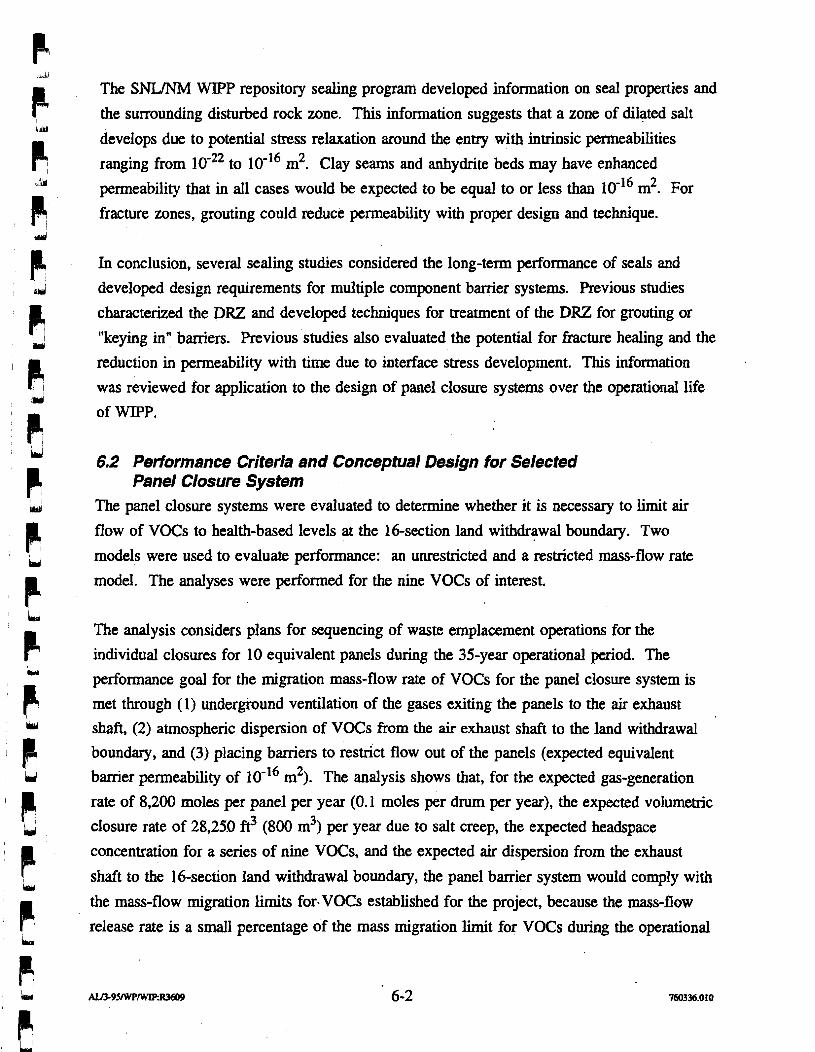
The SNL/NM WlPP repository sealing program developed information on seal properties and
the surrounding disturbed rock zone. This information suggests that a zone of dilated salt
develops due to potential stress relaxation around the entry with intrinsic permeabilities
ranging from to 10-l6 m2. Clay seams and anhydrite beds may have enhanced
permeability that in all cases would be expected to be equal to or less than 10"~ m2. For
fracture zones, grouting could reduce permeability with proper design and technique.
In conclusion, several sealing studies considered the long-term performance of seals and
developed design requirements for multiple component barrier systems. Previous studies
characterized the DRZ and developed techniques for treatment of the DRZ for grouting or
"keying in" barriers. Previous studies also evaluated the potential for fracture healing and the
reduction in permeability with time due to interface stress development. This information
was reviewed for application to the design of panel closure systems over the operational life
of WIPP.
6.2 Performance Criteria and Conceptual Design for Selected Panel Closure System
The panel closure systems were evaluated to determine whether it is necessary to limit air
flow of VOCs to health-based levels at the 16-section land withdrawal boundary. Two
models were used to evaluate performance: an unrestricted and a restricted mass-flow rate
model. The analyses were performed for the nine VOCs of interest.
The analysis considers plans for sequencing of waste emplacement operations for the
individual closures for 10 equivalent panels during the 35-year operational period. The
performance goal for the migration mass-flow rate of VOCs for the panel closure system is
met through (1) underground ventilation of the gases exiting the panels to the air exhaust shaft, (2) atmospheric dispersion of VOCs from the air exhaust shaft to the land withdrawal
boundary, and (3) placing baniers to restrict flow out of the panels (expected equivalent
barrier permeability of 10-l6 m2). The analysis shows that, for the expected gas-generation
rate of 8,200 moles per panel per year (0.1 moles per drum per year), the expected volumetric
closure rate of 28,250 ft? (800 m3) per year due to salt creep, the expected headspace
concentration for a series of nine VOCs, and the expected air dispersion from the exhaust
shaft to the 16-section land withdrawal boundary, the panel barrier system would comply with
the mass-flow migration limits for-VOCs established for the project, because the mass-flow
release rate is a small percentage of the mass migration limit for VOCs during the operational
period. For unrestricted flow, the panel closure system meets mass-flow rate performance
goals established for the project.
In applying a technology assessment to the design of the panel barrier system for the WIPP, it
is concluded that technologies are available for emplacing bulkheads, crushed salt, and grout
curtains. The grouting &sign would consider such factors as the spacing, size and direction
of open joints, rock strength, rock stresses, and uniformity.
6.3 Detailed Design Studies It is recommended that the composite design concept selected based upon the preliminary
analysis be evaluated in future detailed design studies. Where restriction of VOCs is a major
design consideration, these design studies will consider more advanced air-flow analyses of
the migration of contaminants through barriers, the MB 139, and the DRZ surrounding the
panel entry. More detailed structural analyses will be performed to account for air pressure
loading and to assess the extent and recovery of the DRZ. &I important aspect is the tradeoff
in increasing the stress concentration around a shorter rigid concrete plug versus constructing
a long plug to increase flow-path resistance.
7.0 References
Arguello, J. G., 1988, "WIPP Panel Entryway Seal-Numerical Simulation of Seal Composite Interaction for Preliminary Seal Design Evaluation," S'D87-2804, Sandia National Laboratories, Albuquerque, New Mexico.
Arguello, J. G., and T. M. Toms, 1987, "WIPP Panel Entryway Seal-Numerical Simulation of Seal ComponentFormation Interaction for Preliminary Seal Design Evaluation," SAND87-2591, Sandia National Laboratories, Albuquerque, New Mexico.
Borns, J. B., and J. C. Stormont, 1988, "An Interim Report on Excavation Effect Studies at the Waste Isolation Pilot Plant: The Delineation of the Distributed Rock Zone," SAND87-1375, Sandia National Laboratories, Albuquerque, New Mexico.
Brodsky, N. S., 1994, "Measurements of Fluid Transport Properties for Marker Bed 139 Anhydrite from the Waste Isolation Pilot Plant," SI-0491, report prepared by REBPEC Inc., Rapid City, South Dakota.
Bruce, D. A., 1989, "Contemporary Practice in Geotechnical Drilling and Grouting," Keynote Lecture, First Canadian International Grouting Seminar, Toronto, Canada, April 18, 1989, Toronto, Canada.
Brush, L. H., 1994, Position Paper on Gas Generation in the Waste Isolation Pilot Plant, draft for internal WTPP Project Review, September 6, 1994. Scheduled for publication, December 1994
Brush, L. H., 1993 "Likely Gas-Generation Reactions and Current Estimates of Gas-Generation Rates for the Long-Tern WIPP Performance Assessment," unpublished memorandum to M. S. Tierney, June 8, 1993, Sandia National Laboratories, Albuquerque, New Mexico. Scheduled for publication in December 1994.
Brush, L. H., 1991, "Current Estimates of Gas-Production Rates, Gas-Production Potentials, and Expected Chemical Conditions Relevant to Radionuclide Chemistry for the Long-Term WIPP Performance Assessment," Preliminary Comparison with 40 CFR Part 19 1, Subpart B for the Waste Isolation Pilot Plant, December, 1991, Volume 3: Reference Data, WIPP Performance Assessment Division, A-27 to A-36, SAND91-08931'3, Sandia National Laboratories, Albuquerque, New Mexico.
Case, J. B., and P. C. Kelsall, 1987, "Coupled Processes in Repository Sealing," Proceedings of the Symposium on Coupled Processes Associated with Nuclear Waste Repositories, Academic Press, Inc, pp. 590-604.
Cook, R., and J. Case, 1991, "Design and Construction Issues Associated with Sealing of a Repository in Salt," Waste Management '91, Proceedings of the Symposium on Waste Management, Tucson, Arizona, Vol. 2, pp. 735-742.
D'Appolonia Consulting Engineers (D'Appolonia), 1983, "Gassy Mine Evaluation for Repository Design, D7Appolonia Consulting Engineers, Albuquerque, New Mexico.
D' Appolonia Consulting Engineers (D'Appolonia), 1978, "Potential for Hydrocarbon Explosions and Probable Related Impacts in Mechanically Mined Underground Crude Oil Storage Facilities," D'Appolonia Consulting Engineers, Pittsburgh, Pennsylvania
Deere, D. U., and G. Lombardi, 1985, "Grout Slurries-Thick or Thin?," in Proceedings of Issues on Dam Grouting, American Society of Civil Engineers, New York, New York, pp. 156-164.
Fernandez, J. A., and A. M. Richardson, 1994, "A Review of Available Technologies for Sealing a Potential Underground Nuclear Waste Repository at the Yucca Mountain, Nevada," SAND93-3997, Sandia National Laboratories, Albuquerque, New Mexico.
Finley, R. E., and J. R. Tillerson, 1992, "WIPP Small Scale Performance Test--Status and Impacts," SAND91 -2247, Sandia National Laboratories, Albuquerque, New Mexico.
Francke, C. T., and L. J. Temll, 1993, "The Excavation Effekts Program at the Waste- Isolation Pilot Plant," Innovative Mine Design for the 21st Century, Proceedings of the International Congress on Mine Design, August 23-26, 1993, W. F. Bowden and J. F. Archibald, eds., Kingston, Ontario, Canada.
Freeze, A., and J. Cherry, 1979, Groundwater, Prentice Hall, Englewood Cliffs, New Jersey.
Hansen, F. D., M. S. Lin, and L. L. Van Sambeek, 1993, "Concepts for Operational Period Panel Seal Design at the WIPP," SAND93-0729, Sandia National Laboratories, Albuquerque, New Mexico.
Holcomb, D. J., and M. Shields, 1987, "Hydrostatic Creep Consolidation of Crushed Salt with Added Water," SAND87-1990, Sandia National Laboratories, Albuquerque, New Mexico.
Horsemen, S. T., 1988, "Moisture Content-A Major Uncertainty in Storage Cavity Closm Prediction, Second Conference on the Mechanical Behavior of Salt," Trans Tech Publications, pp. 55-68.
Houlsby, A. C., 1990, "Construction and Design of Cement Grouting: A Guide to Grouting in Rock Foundations," John Wiley and Sons, New York, New York, 442 pp.
Houlsby, A. C., 1982, "Cement Grouting for Dams," in Proceedings of the Conference on Grouting in Geotechnical Engineering, W.H. Baker (ed.), American Society of Civil Engineers, New York, New York, pp. 1-34.
IT Corporation 0, 1994, "~ac lb i l Engineering Analysis Report," report prepared for Westinghouse Electric Corporation.
IT Corporation (IT), 1993, "Ground-Penetrating Radar Surveys at the WIPP Site," January 1991 to February 1992, contractor report for Westinghouse Electric Corporation, Albuquerque, New Mexico.
Kelsall, P. C., J. B. Case, W. E. Coons, J. G. Franzone, and D. Meyer, 1985, "Schematic Designs for Penetrations Seals for a Repository in the Permian Basin," BMl.0MV.I-564 prepared by IT Corporation for Offife of Nuclear Waste Isolation, Battelle Memorial Institute, Columbus, Ohio.
Kelsall, J. B. Case, W. E. Coons, R. D. Ellison, and D. Meyer, 1984, "Schematic Designs for Penetration Seals for a Repository in the Permian Basin-Architect-Engineer Turnover Package," report prepared for the Office of Nuclear Waste Isolation, B a M e Memorial Institute, Columbus, Ohio.
Kelsall, P. C., D. Meyer, J. B. Case, and W. E. Coons, 1983, "Schematic Designs for Penetration Seals for a Repository in the Paradox Basin," report prepared for the Battelle Memorial Institute, Office of Nuclear Waste Isolation, Columbus, Ohio.
Kelsall, P. C., J. B. Case, D. Meyer, and W. E. Coons, 1982; "Schematic Designs for Penetration Seals for a Reference Repository in Bedded Salt," OW-405, Office of Nuclear Waste Isolation, Columbus, Ohio.
Lappin, A. R., R. L. Hunter, Editors; D. P. Garber and P. B. Davies, Associate Editors, 1989, "Systems Analysis, Long-Term Radionuclide Transport, and Dose Assessments, Waste Isolation Pilot Plant (WPP), Southeastern New Mexico; March 1989," SAND89-0462, Sandia National Laboratories, Albuquerque, New Mexico.
Lin, M. S. and L. L. Van Sambeek, 1992, "Waste Isolation Pilot Plant Alcove Gas Barrier Final Design Report," SAND92-7307, Sandia National Laboratories, Albuquerque, New Mexico.
McPherson, M. J., 1993, "Subsurface Ventilation and Environmental Engineering," Chapman C. Hull, New York, New York.
Nowak, E. J., J. R. Tillerson, and T. M. Torres, 1990, "Initial Reference Seal System Design: WIPP," SAND90-0355, Sandia National Laboratories, Albuquerque, New Mexico.
Peach, C. J., C. J. Spiers, A. J. Tankink, and H. J. Zwart, 1987, "Fluid and Ionic Transport Properties of Deformed Salt Rock," Commission of the European Communities Report EUR 10926.
Peterson, E. W., P. L. Lagus, and K. Lie, 1987, "Fluid Flow Measurements of Test Series A and B for the Small Scale Seal Performance Tests," SAND87-7041, Sandia National Laboratories, Albuquerque, New Mexico.
Peterson, E., Lagus, P., and Lie, K., 1985, WIPP Horizon In Situ Permeability Measurements Final Report," SAND8.5-7166, Sandia National Laboratories, Albuquerque, New Mexico.
Ratigan, J. L., L. L. Van Sambeek, K. L. De Vries, and J. D. Nieland, 1991, "The Influence of Seal Design On The Development Of The Disturbed Rock Zone In The WIPP Alcove Seal Tests," RSI-0400, prepared by REfSPEC Inc., Rapid City, South Dakota.
Sandia National LaboratoriesINew Mexico (SNIJNM), 1992 "Preliminary Performance Assessment for the Waste Isolation Pilot Plant, December, 1992," SAND92-0700, Sandia National Laboratories, Albuquerque, New Mexico.
Sandia National LaboratoriesLNew Mexico (SNWNM), 1991, "Preliminary Comparison with 40 CFR Part 191, Subpart B for the Waste Isolation Pilot Plant, December 1991," SAND91-0893, Sandia National Laboratories, Albuquerque, New Mexico.
Sjaardema, G. D., and R. D. Krieg, 1987, "A Constitutive Model for the Consolidation of WIPP Crushed Salt and Its Use in Analyses of Backfilled Shaft and Drift Configurations," SAND87-1977, Sandia National Laboratories, Albuquerque, New Mexico.
Slezak, S., 1990, "Potential for and Possible Impacts of Generation of Flammable andlor Detonable Gas Mixtures During the WIPP Transportation, Test, and Operational Phases," SNL MEMO to D. Mercer, and C. Fredrickson, Sandia National Laboratories, Albuquerque, New Mexico.
SNL, see Sandia National LaboratoriesNew Mexico.
Storrnont, J. C., 1991, "Gas Flow Measurements as Index Tests for the Disturbed Rock Zone," Memorandum to Distriiution, Sandia National Laboratories, Albuquerque, New Mexico.
Stormont, J. C., 1990, "Summary of 1988 WIPP Facility Horizon Gas Flow Measurements," SAND89-2497, Sandia National Laboratories, Albuquerque, New Mexico.
Storrnont, J. C., 1988, "Preliminary Seal Design Evaluation for the Waste Isolation Pilot Plant," SAND87-3083, Sandia National Laboratories, Albuquerque, New Mexico.
Storrnont, J. C., 1987, "Small-Scale Seal Performance Test Series "A" Thermal/Structural Data Through the 180th Day," SAND87-OI 78, Sandia National Laboratories, Albuquerque, New Mexico.
Stormont, J. C., 1985, "Test Plan: Small-Scale Seal Performance Tests," Sandia National Laboratories, Albuquerque, New Mexico.
Stomont, J. C., 1984, "Plugging and Sealing Program for the Waste Isolation Pilot Plant," SAND84-1057, Sandia National Lgboratories, Albuquerque, New Mexico.
Stormont, J. C., and C. L. Howard, 1987, "Development, Implementation and Early Results: Test Series C of the Small-Scale Seal Performance Tests," SAND87-2203, Sandia National Laboratories, Albuquerque, New Mexico.
Stormont, J. C., C. L. Howard, and J. J. K. Daemen, 1991, "In Situ Measurements of Rock Salt Permeability Changes Due to Nearby Excavation," SAND90-3134, Sandia National Laboratories, Albuquerque, New Mexico.
Stormont, J. C., E. W. Peterson, and P. L. Lagus, 1987, "Summary of the Observations About WIPP Facility Horizon Flow Measurements Through 1986," SAND87-0176, Sandia National Laboratories, Albuquerque, New Mexico.
Telander, M. R., and R. E. Westerman, 1993, "Hydrogen Generation by Metal Corrosion in Simulated Waste Isolation Plant Environments," S ' 9 2 - 7 3 4 7 , Sandia National Laboratories, Albuquerque, New Mexico.
I
Torres, T. M., C. L. Howard, and R. E. F i e y , 1991, "Development, Implementation, and Early Results: Test Series D, Phase 1 of the Small-Scale Seal Performance Tests," SAND91 -2001, Sandia National Laboratories, Albuquerque, New Mexico.
Torres, T. M., and C. L. Howard, 1990, "SSSPT-D, Phase 2: Implementation and Status of Brine Inflow Testing on Bentonite Seal LIDES," Memo to Distribution, Sandia National ~aboratories, Albuquerque, New Mexico.
Torres, T. M., and C. L. Howard, 1989, "Addendum C2: Brine Flow-Permeability Performance and Additional Activities Required for Small-Scale Seal Performance Tests-Test Series C (SaltBentonite Block Seal Emplacements)," Memo to Distribution, Sandia National Laboratories, Albuquerque, New Mexico.
U.S. Department of Energy (DOE), 1994% "Panel One Utilization Plan," W?PP/W.ID-94-2027, Westinghouse Electric Corporation, Carlsbad, New Mexico.
U.S. Department of Energy (DOE), 1994b, "Geotechnical Analysis Report, July 1992 through June 1993," DOE-WIPP 94-006, U.S. Department of Energy, Washington D.C.
U.S. Department of Energy (DOE), 1991, "Waste Acceptance Criteria for the Waste Isolation Pilot Plant," WIPP-DOE-069, Rev. 4, U.S. Department of Energy, Washington, D.C.
U.S. Department of Energy (DOE), 1990, "Final Safety Analysis Report (FSAR), Waste Isolation Pilot Plant,".WP 02-9, Rev. 0, U.S. Department of Energy, Washington, D.C.
U.S. Department of Energy (DOE), 1988, Geotechnical Field Data and Analysis Report, July 1986 through June 1987, DOHWPP Report 87-017.
U.S. Department of Energy (DOE), 1986% "Waste Isolation Pilot Plant Design Validation Final Report," D O W I P 86-010, report prepared by Bechtel National, Inc., San Francisco, California.
U.S. Department of Energy (DOE), 1986b, "Interim Geotechnical Field Data," U.S. Department of Energy Report, DOWIPP 86-012, report prepared by Bechtel National, Inc. for the U.S. Department of Energy, San Francisco, California.
U.S. Environmental Protection Agency (EPA), 1994, "Standards for Owners and Operators of Hazardous Waste Treatment, Storage, and Disposal Facilities," 40 CFR Part 264, U.S. Environmental Protection Agency, Washington, D.C.
Van Sambeek, L. L., D. D. Luo, M. S. Lin, W. Ostrowski and D. Oyenuga, 1993a, "Seal Design Alternative Study," SAND92-7340, Sandia National Laboratories, Albuquerque, New Mexico.
Van Sambeek, L. L., J. L. Ratigan, and F. D. Hansen, 19934 "Dilatancy of R a k Salt in I d Laboratory Tests," Int. J. Rock Mech. Min. Sci. and Geomech. Abstr., Great Britain,
I' lpi Westinghouse Electric Corporation, 1995a, "Underground Hazardous Waste Management Unit
I Closure Criteria for the Waste Isolation Pilot Plant Operational Phase, hdecisional Draft," WIDNIPP-Draf-2038, February 1995, Westinghouse Electric Corporation, Waste Isolation Division, Carlsbad, New Mexico.
P Westinghouse Electric Corporation, 19954 "25 Year Underground Waste Emp1acement Throughput Schedule for Remote Handled Transuranic and Contact Handled Transuranic Waste Containers Report," DOWIPP-DRAFT-2066, January 1995, Westinghouse Electric Corporation, Waste Isolation Division, Carlsbad, New Mexico.
kmd
Westinghouse Electric Corporqtion, 1987, "Waste Drum Fire Propagation at the Waste t Isolation Pilot Plant," DOUWIPP-87-005, Westinghouse Electric Corporation, Waste Isolation Pilot Plant, Carlsbad, New Mexico.
APPENDIX A DERIVATION OF RELATIONSHIPS FOR THE GAS MODEL
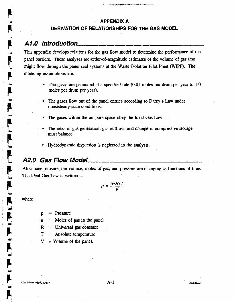
APPENDIX A DERIVATION OF RELATIONSHIPS FOR THE GAS MODEL
A I . 0 Introduction This appendix develops relations for the gas flow model to determine the performance of the
panel barriers. These analyses are order-of-magmtude estimates of the volume of gas that
might flow through the panel seal systems at the Waste Isolation Pilot Plant (WIPP). The
modeling assumptions are:
The gases are generated at a specified rate (0.01 moles per drum per year to 1.0 moles per drum per year).
The gases flow out of the panel entries according to Darcy's Law under quasisteady-state conditions.
The gases within the air pore space obey the Ideal Gas Law.
The rates of gas generation, gas outflow, and change in compressive storage must balance.
Hydrodynamic dispersion is neglected in the analysis.
A2.0 Gas Flow Model After panel closure, the volume, moles of gas, and pressure are changing as functions of time.
The Ideal Gas Law is written as:
where
p = Pressure
n = Moles of gas in the panel
R = Universal gas constant
T = Absolute temperature
V = Volume of the panel.
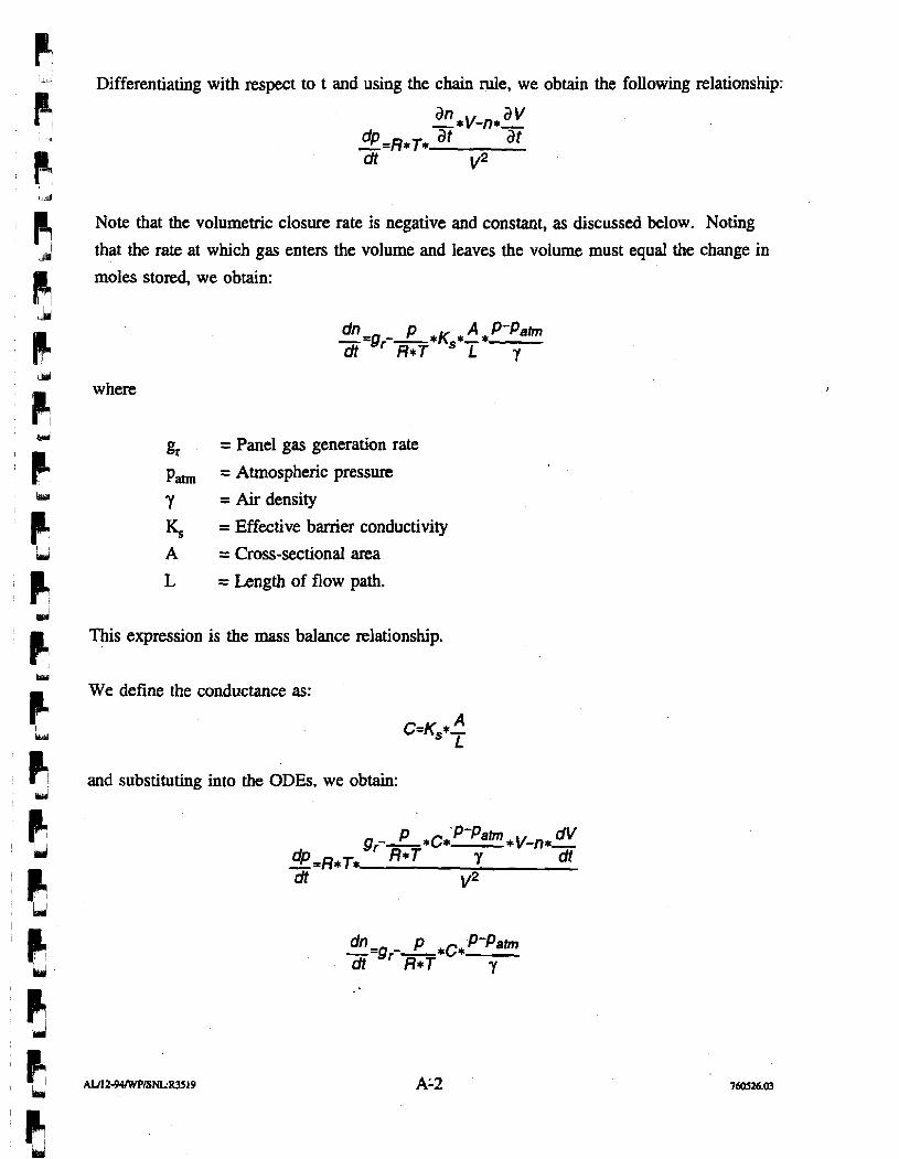
Differentiating with respect to t and using the chain rule, we obtain the following relationship:
Note that the volumetric closure rate is negative and constant, as discussed below. Noting
that the rate at which gas enters the volume and leaves the volume must equal the change in
moles stored, we obtain:
where
gr = Panel gas generation rate
p, = Atmospheric pressure
Y = Air density K, = Effective banier conductivity
A = Cross-sectional area
L = Length of flow path.
This expression is the mass balance relationship.
We define the conductance as:
and substituting into the ODES, we obtain:
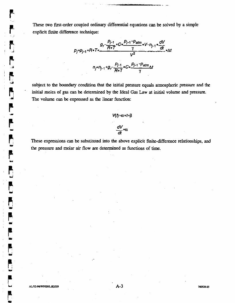
-3
P These two fust-order coupled ordinary differential equations can be solved by a simple
explicit fmite difference technique: Id
d subject to the boundary condition that the initial presswe equals atmospheric pressure and the
' [ '
initial moles of gas can be determined by the Ideal Gas Law at initial volume and pressure.
The volume can be expressed as the linear function:
dt
These expressions can be substituted into the above explicit finite-difference relationships, and bui
the presswe and molar air flow are determined as functions of time.
P
APPENDIX B
I! IpJ
CALCULATIONS IN SUPPORT OF PANEL GAS PRESSURIZATION DUE TO CREEP CLOSURE
APPENDIX B CALCULATIONS IN SUPPORT OF PANEL GAS PRESSURIZATION DUE TO CREEP CLOSURE
B 1.0 introduction This appendix presents the closure mechanisms and supporting calculations for panel
volumetric closure for the analysis of gas pressurization within a closed panel at the Waste
Isolation Pilot Plant (WIPP). The volume reduction is due to the panel volume change from
viscoplastic secondary creep closure of the walls, roof, and floor. As the walls, roof, and
floor of the excavations within a panel converge, the total volume of the panel decreases.
The volumetric closure of a panel is the result of several different mechanisms working in
tandem. These mechanisms include:
Viscoplastic secondary creep of the salt toward the excavation
Fracturing in the roof and floor caused by the deviatoric stresses around the excavation
Bed separation at the clay seams in the roof and below Marker Bed 139 in the floor.
These mechanisms are described in detail in Chapter 3 of this report.
The combination of these three mechanisms leads to the observed excavation face
convergence rates observed in Panel 1. Of these mechanisms, only secondary creep of the salt reduces the total volume of the panel and pore space in the surrounding disturbed rock
zone (DRZ). Fracturing in the roof and floor and bed separation transfer the void volume within the excavation to the DRZ. This void volume within the DRZ is assumed to be
interconnected with the open excavation. Therefore the total reduction in volume within the
panel based simply on room closure, overestimates the effective reduction in void volume.
However, quantifying the amount of interconnected void space within the DRZ would require
a much more detailed analysis. The total volume change calculated from the room closure
measurements is therefore considered conservative.
Other assumptions made in this calculation are:
The volumetric closure rates are constant after panel closure after approximately four years.
The waste in the panel provides no significant resistance to creep closure during the initial 35 years of panel life.
The air volume is the total volume of the excavations minus the solid volume of the waste in drums or waste packages. This is estimated to equal 138,000 (3,908 m3).
The closure rate of each room in the panel equals the closure rate at the midpoint of the room.
The length of each room or drift is constant; to simplify the calculations, only the width and height change with creep closure.
The panel is comprised of seven rooms and two panel drifts. The alcove entries in Panel 1 are not included in the volume calculations.
82.0 Panel Volume Change Calculnrtion The panel volume change calculation is performed by fmt calculating the initial panel
volume, then calculating the room and drift closure rates, and finally calculating the panel
volumetric closure rate. Following is a detailed description of each part of the calculation.
82.1 Initial Panel Volume The initial panel volume is the volume of the panel immediately after completion of
excavation. The total volume is calculated by summing the individual room and drift
volumes within the panel. These volumes are based on the as-built dimensions of the
excavated rooms and drifts in Panel 1 (DOE, 1993). Figure B-1 identifies the rooms and
drifts in Panel 1. Table B-1 presents the room and drift dimensions and the calculated
volume of each room and drift. The volume of the panel entries between East 300 and
Room 1 is not included.
The total initial volume of Panel 1 is 1,669,434 ft3 (47,273 m3).
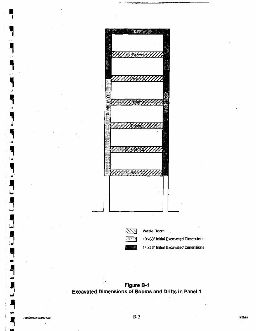
Waste Room
1 73x33" Initial Excavated Dimensions
14'x33" Initial Excavated Dimensions
Figure B-1 Excavated Dimensions of Rooms and Drifts in Panel 1
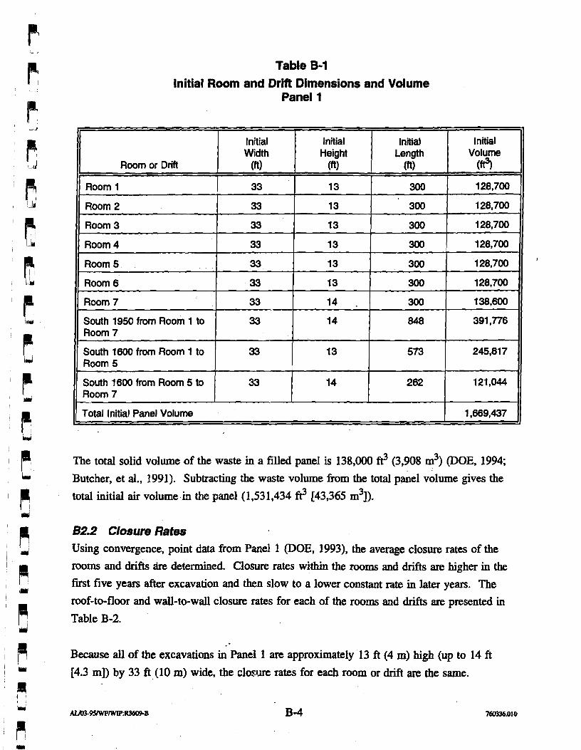
Table B-1 lnitial Room and Drift Dimensions and Volume
Panel 1
The total solid volume of the waste in a filled panel is 138,000 ft3 (3,908 m3) (DOE, 1994;
Butcher, et al., 1991). Subtracting the waste volume from the total panel volume gives the
total initial air vo1ume.i~ the panel (1,531,434 ft3 [43,365 m3]).
82.2 Closure Rates Using convergence, point data from Panel 1 (DOE, 1993), the average closure rates of the
rooms and drifts &e determined. Closure rates within the rooms and drifts are higher in the
fust five years after excavation and then slow to a lower constant rate in later years. The
roof-to-floor and wall-to-wall closure rates for each of the rooms and drifts are presented in
Table B-2.
7
Because all of the excavations in Panel 1 are approximately 13 ft (4 m) high (up to 14 ft
Room or Drift
Room 1
Room 2
Room 3
Room 4
Room 5
Room 6
Room 7
South 1950 from Room 1 to Room 7
South 1600 from Room 1 to Room 5
South 1600 from Room 5 to Room 7
[4.3 m]) by 33 ft (10 m) wide, the closure rates for each room or drift are the same.
Initial Wi ih
(a) 33
33
33
33
33
33
33
33
33
33
Initial Volume
1 28,700
128,700
128,700
128,700
128,700
128,700
138,600
391,776
245,817
121,044
Total Initial Panel Volume
Initial Height
(fi)
13
13
13
13
13
13
14 . 14
13
14
1,669,437
Initial Length
(fi)
300
300
300
300
300
300
300
848
573
262
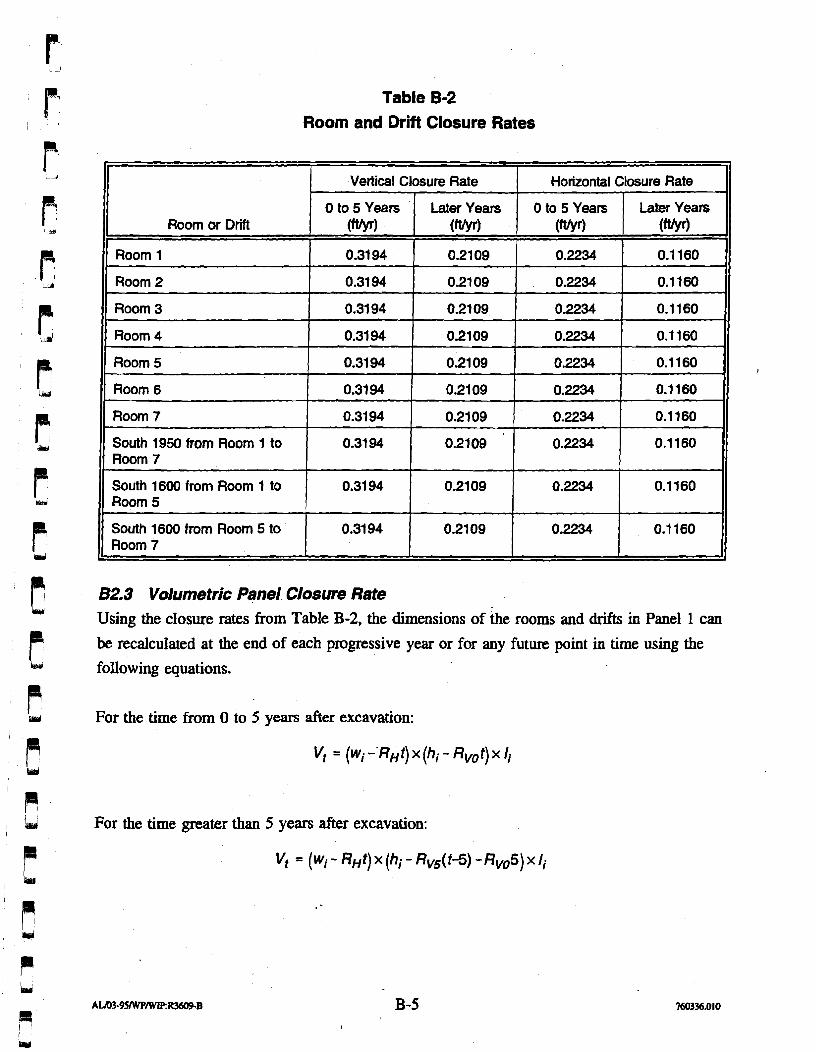
Table 8-2 Room and Drift Closure Rates
Vertical Closure Rate Hotizontal Closure Rate 11 I 0 to 5 Years I Later Years I 0 to 5 Years 1 Later Years 11
I!
)I Room 3 1 0.31 94 1 0.2109 0.2234 0.1160 I(
Room or Drift
Room 1
Room 2
11 Room 4 0.31 94 0.2109 0.2234 0 6 0 11 1) Room 5 1 0.3194 1 0.2109 1 0.2234 ( 0.1160 11
(MI I ( ft/yr)
0.31 94
0.31 94
(tt/yr)
B2.3 Volumetric Panel Closure Rate Using the closure rates from Table B-2, the dimensions of the rooms and drifts in Panel 1 can be recalculated at the end of each progressive year or for any future point in time using the following equations.
0.21 09
0.21 09
Room 7
South 1950 from Room 1 to Room 7
South 1600 from Room 1 to Room 5
South 1600 from Room 5 to Room 7
For the time from 0 to 5 years after excavation:
Vt = (wi -'RHt) x (hi - Rvot) x li
For the time greater than 5 years after excavation:
0.2234
0.2234
0.31 94
0.31 94
0.31 94
0.31 94
0.1 160
0.1 160
0.21 09
0.2109
0.2109
0.21 09
0.2234
0.2234
0.2234
0.2234
0.1 160
0.1160
0.1160
0.1 160
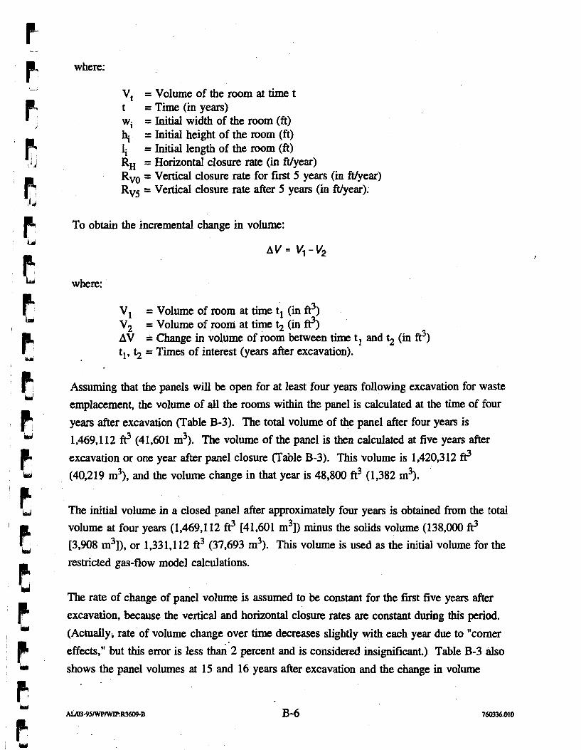
where:
V, = Volume of the room at time t t = Time (in years) wi = Initial width of the room (ft) hi = Initial height of the room (ft) li = Initial length of the room (ft) RH = Horizontal closure rate (in ftlyear) Rvo = Vertical closure rate for first 5 years (in ftlyear)
Rvs = Vertical closure rate after 5 years (in ftlyear).
To obtain the incremental change in volume:
where:
V, = Volume of room at time t1 (in ft3)
V2 = Volume of room at time fi (in p) AV = Change in volume of room between time t1 and 12 (in ft3) tl, fi = Times of interest (years after excavation).
Assuming that the panels will be open for at least four years following excavation for waste
emplacement, the volume of all the rooms within the panel is calculated at the time of four
years after excavation (Table B-3). The total volume of the panel after four years is
1,469.1 12 fl? (4 1,601 m3). The volume of the panel is then calculated at five years after
excavation or one year after panel closure (Table 8-3). This volume is 1,420,312 @ (40,219 m3), and the volume change in that year is 48,800 ft3 (1,382 m3).
The initial volume in a closed panel after approximately four years is obtained from the total
volume at four years (1.469.1 12 ft? [41,601 m3]) minus the solids volume (138,000 ft? 13,908 m3]), or 1,331,112 d (37,693 m3). This volume is used as the initial volume for the
restricted gas-flow model calculations.
The rate of change of panel volume is assumed to be constant for the first five years after
excavation, because the vertical and horizontal closure rates are constant during this period.
(Actually, rate of volume change over time decreases slightly with each year due to "comer
effects," but this error is less thad.2 percent and is considered insignificant.) Table B-3 also
shows the panel volumes at 15 and 16 years after excavation and the change in volume
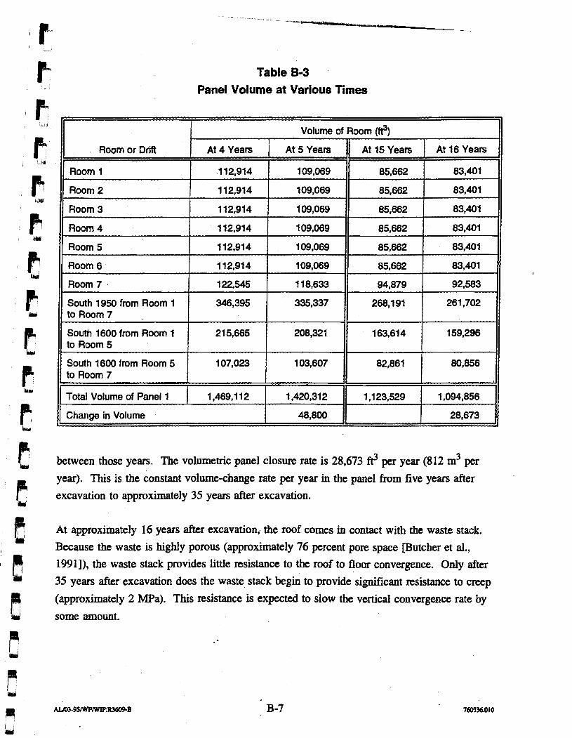
P Table B-3 - > Panel Volume at Various Times
Volume of Room (ft3)
Room or Drift At 15 Years At 16 Years
Total Volume of Panel 1 1,469,112 1,420,312 1,094,856
Change in Volume 48,800 -
between those years. The volumetric panel closure rate is 28,673 @ per year (812 m3 per
year). This is the constant volume-change rate per year in the panel from five years after
excavation to approximately 35 years after excavation.
At approximately 16 years after excavation, the roof comes in contact with the waste stack.
Because the waste is highly porous (approximately 76 percent pore space [Butcher et al., 1991 I), the waste stack provides little resistance to the roof to floor convergence. Only after
35 years after excavation does the waste stack begin to provide significant resistance to creep
(approximately 2 MPa). This resistance is expected to slow the vertical convergence rate by
some amount.
References
Butcher, B. M., T. W. Thompson, R. G. VanBuslcirk, N. C. Patti, 1991, "Mechanical Compaction of Waste Isolation Pilot Plant Simulated Waste," SAND90-1206, Sandia National Laboratories, New Mexico
U.S. Department of Energy (DOE), 1993, "Geotechnical Analysis Report, July 199 1 through June 1992," DOE-WIPP 93-019, U.S. Department of Energy, Washington D.C.
U.S. Department of Energy (DOE), 1994, "Panel One Utilization Plan," WIPPIWID-94-2027, Westinghouse Electric Corporation, Carlsbad, New Mexico.
APPENDIX C STRUCTURAL DESIGN CALCULATIONS
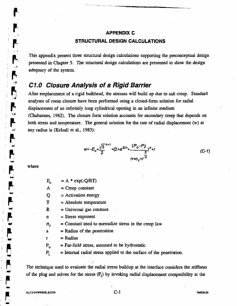
APPENDIX C
STRUCTURAL DESIGN CALCULATIONS
This appendix present three structural design calculations supporting the preconceptual design
presented in Chapter 5. The structural design calculations are presented to show the design
adequacy of the system.
CI.0 Closure Analysis of a Rigid Barrier After emplacement of a rigid bulkhead, the stresses will build up due to salt creep. Standard
analyses of room closure have been performed using a closed-form solution for radial
displacement of an infinitely long cylindrical opening in an infinite medium
(Chabannes, 1982). The closure form solution accounts for secondary creep that depends on
both stress and temperature. The general solution for the rate of radial displacement (w) at any radius is (Kelsall et al., 1983):
where
E~ = A * exp(-QRT) A = Creep constant
Q = Activation energy
T = Absolute temperature R = Universal gas constant
n = Stress exponent
Gc = Constant used to normalize stress in the creep law
a = Radius of the penetration
r = Radius
Po = Far-field stress, assumed to be hydrostatic
'i = Internal radial stress applied to the surface of the penetration.
The technique used to evaluate the radial stress buildup at the interface considers the stiffness
of the plug and solves for the stress (Pi) by invoking radial displacement compatibility at the
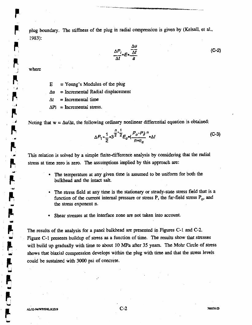
plug boundary. The stiffness of the plug in radial compression is given by (Kelsall, et al.,
1983):
where
E = Young's Modulus of the plug
Au = Incremental Radial displacement
At = Incremental time
APi = Incremental stress.
Noting that w = AdAt, the following ordinary nonlinear differential equation is obtained:
This relation is solved by a simple finite-difference analysis by considering that the radial
stress at time zero is zero. The assumptions implied by this approach are:
The temperature at any given time is assumed to be uniform for both the bulkhead and the intact salt.
The stress field at any time is the stationary or steady-state stress field that is a function of the current internal pressure or stress P, the far-field stress Po, and the stress exponent n.
Shear stresses at the interface zone are not taken into account.
The results of the analysis for a panel bulkhead are presented in Figures C-1 and C-2.
Figure C-1 presents buildup of stress as a function of time. The results show that stresses
will build up gradually with time to about 10 MPa after 35 years. The Mohr Circle of stress
shows that biaxial compression develops within the plug with time and that the stress levels
could be sustained with 3000 psi of concrete.
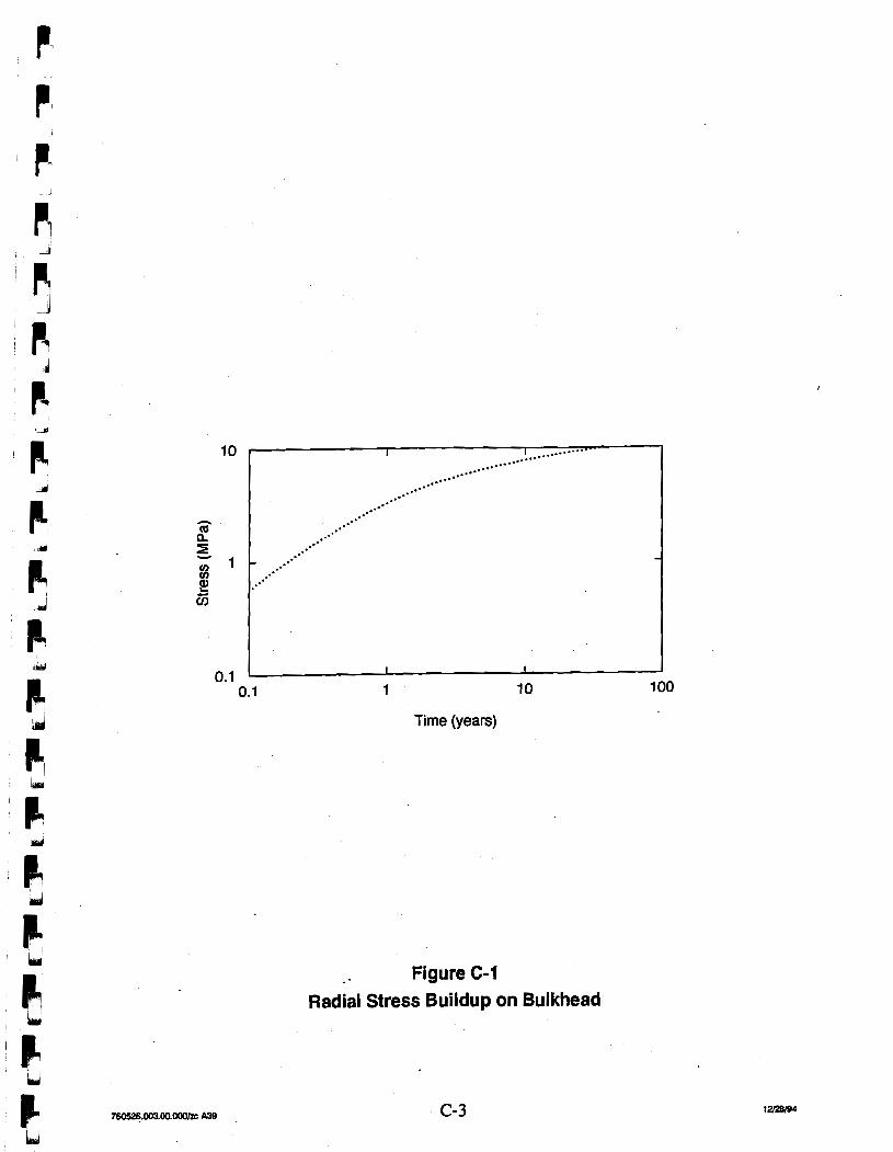
Time (years)
Figure C-1 Radial Stress Buildup on Bulkhead
1 2 3 4 5 6 7 8 9 10
Normal Stress (MPa)
. . - . Stress after 1 year
- - - Stress after 10 years
Stress after 35 years
Figure C-2 Mohr Circles of Stress
C2.0 Dynamic Analysis of a Methane Explosion The technical approach is to determine the mass and stiffness of the bulkhead at the time that
a methane explosion might occur, to determine the potential loading on the bulkhead from a
methane explosion, to determine the expected stress from a methane explosion, and to
combine this with other stresses. The stress is compared to the strength of the concrete
bulkhead and salt foundation to assure that the bulkhead remains stable.
The bulkhead is modeled by a very thick beam. The displacement as function of the pressure
loading is given by (Timoshenko, 1970):
where
6 = Deflection of the uniformly loaded beam
E = Young's modulus of concrete
I = Moment of Inertia
c = Bulkhead half thickness (21 ft)
1 = Bulkhead half height (10.5 ft)
q = Uniform linear loading (pounds per linear foot)
v = Poisson's ratio.
The spring constant can be detemined from the stiffness and the mass of the plug. The
fundamental frequency can be determined for the plug from:
Where
f = Fundamental frequency of the structure
K = Stiffness of the structure
M = Mass of the structure.
luri' The calculated fundamental frequency is over 100 cycles per second, and the structure is
)1 considered very rigid. The maximum load factor for a triangular pulse is 2. Slezak (1990) I u
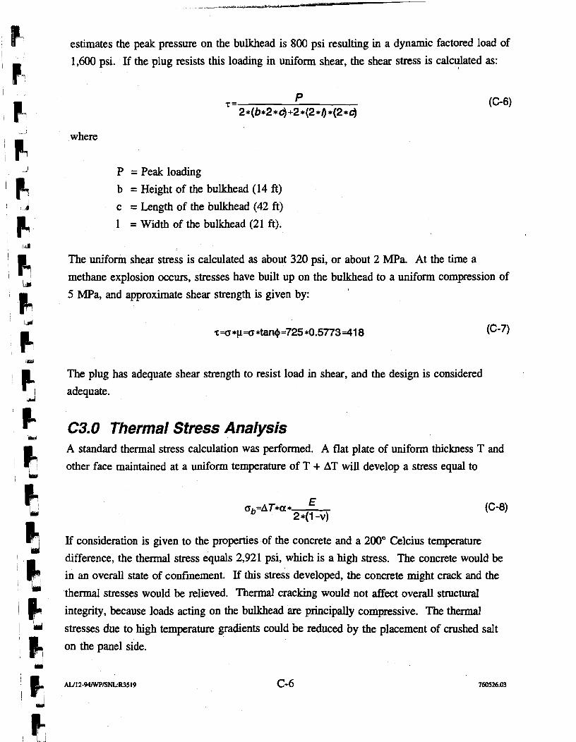
estimates the peak pressure on the bulkhead is 800 psi resulting in a dynamic factored load of
1,600 psi. If the plug resists this loading in uniform shear, the shear stress is calculated as: I
where
P = Peak loading
b = Height of the bulkhead (14 ft)
c = Length of the bulkhead (42 ft)
1 = Width of the bulkhead (21 ft).
The uniform shear stress is calculated as about 320 psi, or about 2 MPa. At the time a
methane explosion occurs, stresses have built up on the bulkhead to a uniform compression of
5 MPa, and approximate shear strength is given by:
The plug has adequate shear strength to resist load in shear, and the design is considered
adequate.
C3.0 Thermal Stress Analysis A standard thermal stress calculation was performed. A flat plate of uniform thickness T and
other face maintained at a uniform temperature of T + AT will develop a stress equal to
If consideration is given to the properties of the concrete and a 200" Celcius temperature
difference, the thermal stress equals 2,921 psi, which is a high stress. The concrete would be
in an overall state of confinement. If this stress developed, the concrete might crack and the
thermal stresses would be relieved. Thermal cracking would not affect overall structural
integrity, because loads acting on the bulkhead are principally compressive. The thermal
stresses due to high temperature gradients could be reduced by the placement of crushed salt
on the panel side.
References
Chabannes, C., 1982, "An Evaluation of the Time-Dependent Behavior of Solution Mined Caverns in Salt for the Storage of Natural Gas," Masters Thesis, Pennsylvania State University.
Kelsall, P. C., J. B. Case, D. Meyer, J. G. Franzone, and W. E. Coons, 1983, "Schematic Designs for Penetration Seals for a Repository in Richton Dome," D'Appolonia Report, Albuquerque, New Mexico.
Slezak, S., 1990, "Potential for and Possible Impacts of Generation of Flammable andlor Detonable Gas Mixtures During the WIPP Transportation, Test, and Operational Phases," Memo to D. Mercer and C. Fredrickson, Sandia National Laboratories, Albuquerque, New Mexico.
Timoshenko, S. P., and J. N. Goodier 1970, Theory of Elasticity, McGraw Hill, New York.