Embed Size (px)
Citation preview
1
Conceptual Designs for the Conversion of the U.S. Great Lakes Steam Bulk Carriers to LNG Fueled Propulsion Final Report Michael G. Parsons Arthur F. Thurnau Professor Emeritus Professor Emeritus of Naval Architecture and Marine Engineering Phone: 734-945-2886; FAX: 734-936-8820; e-mail [email protected] Consultants: Patrick J. O’Hern Great Lakes Maritime Consultants, LLC Phone: 920-493-2439; e-mail [email protected] Richard W. Harkins Harkins Engineering & Environmental Services, LLC Phone: 440-364-4665; e-mail goblue1011@sbcglobal January 30, 2013 Department of Naval Architecture and Marine Engineering University of Michigan 2600 Draper Drive Ann Arbor, MI 48109-2145
This report represents the results of research conducted by the authors and does not necessarily represent the views or policies of the Great Lakes Maritime Research Institute. This report does not contain a standard or specified technique. The authors and the Great Lakes Maritime Research Institute do not endorse products or manufacturers. Trade or manufacturers’ names appear herein solely because they are considered essential to this report.
Research funded in part by the Great Lakes Maritime Research Institute. This study was supported by the U.S. Maritime Administration

2
Cooperative Agreement #DTMA1H11002.
3
The Potential Conversion of the U.S. Great Lakes Steam Bulk Carriers to LNG Propulsion – Final Report Michael G. Parsons1, Patrick J. O’Hern2, Richard W. Harkins3 and Samuel J. Denomy4
1 Arthur F. Thurnau Professor Emeritus, Naval Architecture and Marine Engineering, University of Michigan, Ann Arbor, MI 2 Great Lakes Maritime Consulting, LLC, Brussels, WI 3 Harkins Engineering & Environmental Services, LLC, Rocky River, OH 4 Undergraduate student, Naval Architecture and Marine Engineering, University of Michigan, Ann Arbor, MI; now Bay Shipbuilding, Sturgeon Bay, WI
___________________________________________________________________________________________________________
The feasibility and potential benefits of converting ten remaining U.S. flag Great Lakes steamship bulk carriers to Liquefied Natural Gas (LNG) propulsion using gas engines is investigated. This is the final report of a study that was initially reported at the February 24, 2012, SNAME Section Meeting in Cleveland, OH. The evolving marine air emissions standards and the movement to LNG fuel in U.S. and international non-LNG carriers and the general case for the possible conversion of the remaining U.S. flag Great Lakes steamship bulk carriers to LNG fuel were outlined in the initial report. In this sequel, the final results of a conceptual design study on the conversion of the three AAA class vessels (SS Arthur M. Anderson, SS Cason J. Callaway, SS Philip R. Clarke), focusing primarily on operational and arrangement feasibility and remaining life-cycle economics are presented. Three cases, a pure diesel conversion, a single-fuel LNG conversion, and a dual-fuel LNG/diesel conversion, are compared. Keywords: Great Lakes; bulk carriers; LNG; fuel efficiency; emissions _________________________________________________________________________
1. Introduction
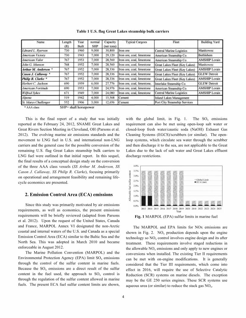
There are 12 remaining U. S. flagged Great Lakes steamship bulk carriers as shown in Table 1. It appears that ten of these are possible candidates for conversion to the use of Liquefied Natural Gas (LNG) as fuel. The smaller, older cement carriers Alpena and St Marys Challenger have primarily been used for storage in recent years. Thus, the ten vessels above the bold line in Table 1 are the focus of this study. Of these, the three designated in bold were built to essentially the same plans and are called the AAA class. (A total of eight vessels were built to essentially similar plans and are sometimes also referred to as AAA vessels.) The three AAA vessels are the primary focus of this study. With the exception of the Edward L. Ryerson and the Herbert C. Jackson, eight of the vessels use essentially the same 7000 normal shaft horsepower cross-compound steam plants, with the same steam conditions, driving fixed-pitch
propellers through a double reduction gear. Most were built to a length of 647ʹ′, beam 70ʹ′ and depth 36ʹ′ and then lengthened to 767ʹ′ and converted to self-unloaders in the 1970’s. The Edward L. Ryerson is the only remaining straight-decker; the John G. Munson was the only one initially built as a self-unloader. From a practical standpoint, the Great Lakes steamship bulk carriers will be unable to meet current air emissions standards unless they are converted to either diesel or LNG propulsion. Their steam plants are also very inefficient by current standards and they require greater manning. These vessels will, therefore, benefit from conversion based upon fuel efficiency, manning, and air emissions. Although most are already 60 years old, by having operated in fresh water the hulls have meaningful economic life remaining if the propulsion can meet the Emission Control Area (ECA) air emission requirements applicable to the Great Lakes.
4
Table 1 U.S. flag Great Lakes steamship bulk carriers
This is the final report of a study that was initially reported at the February 24, 2012, SNAME Great Lakes and Great Rivers Section Meeting in Cleveland, OH (Parsons et al. 2012). The evolving marine air emissions standards and the movement to LNG fuel in U.S. and international non-LNG carriers and the general case for the possible conversion of the remaining U.S. flag Great Lakes steamship bulk carriers to LNG fuel were outlined in that initial report. In this sequel, the final results of a conceptual design study on the conversion of the three AAA class vessels (SS Arthur M. Anderson, SS Cason J. Callaway, SS Philip R. Clarke), focusing primarily on operational and arrangement feasibility and remaining life-cycle economics are presented.
2. Emission Control Area (ECA) emissions
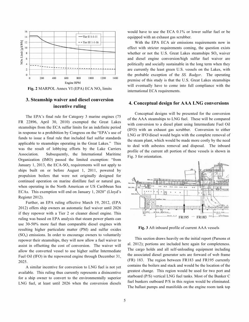
Since this study was primarily motivated by air emissions requirements, as well as economics, the present emissions requirements will be briefly reviewed (adapted from Parsons et al. 2012). Upon the request of the United States, Canada and France, MARPOL Annex VI designated the non-Arctic coastal and internal waters of the U.S. and Canada as a special Emission Control Area (ECA) similar to the Baltic Sea and the North Sea. This was adopted in March 2010 and became enforceable in August 2012. The Marine Pollution Convention (MARPOL) and the Environmental Protection Agency (EPA) limit SOx emissions through the control of the sulfur content in marine fuels. Because the SOx emissions are a direct result of the sulfur content in the fuel used, the approach to SOx control is through the regulation of the sulfur content allowed in marine fuels. The present ECA fuel sulfur content limits are shown,
with the global limit, in Fig. 1. The SOx emissions requirement can also be met using open-loop salt water or closed-loop fresh water/caustic soda (NaOH) Exhaust Gas Cleaning Systems (EGCS)/scrubbers (or similar). The open-loop systems, which circulate sea water through the scrubber and then discharge it to the sea, are not applicable to the Great Lakes due to the lack of salt water and Great Lakes effluent discharge restrictions.
Fig. 1 MARPOL (EPA) sulfur limits in marine fuel
The MARPOL and EPA limits for NOx emissions are shown in Fig. 2. NOx production depends upon the engine technology so NOx control involves engine design and its after treatment. These requirements involve staged reductions in the allowable NOx emissions and only apply to new engines or conversions when installed. The existing Tier II requirements can be met with on-engine modifications. It is generally considered that the Tier III requirements, which come into effect in 2016, will require the use of Selective Catalytic Reduction (SCR) systems on marine diesels. The exception may be the GE 250 series engines. These SCR systems use aqueous urea (or similar) to reduce the stack gas NOx.
5
Fig. 2 MARPOL Annex VI (EPA) ECA NOx limits
3. Steamship waiver and diesel conversion
incentive ruling The EPA’s final rule for Category 3 marine engines (75 FR 22896, April 30, 2010) exempted the Great Lakes steamships from the ECA sulfur limits for an indefinite period in response to a prohibition by Congress on the “EPA’s use of funds to issue a final rule that included fuel sulfur standards applicable to steamships operating in the Great Lakes.” This was the result of lobbying efforts by the Lake Carriers Association. Subsequently, the International Maritime Organization (IMO) passed the limited exemption: “from January 1, 2013, the ECA-SOx requirements will not apply to ships built on or before August 1, 2011, powered by propulsion boilers that were not originally designed for continued operation on marine distillate fuel or natural gas, when operating in the North American or US Caribbean Sea ECAs. This exemption will end on January 1, 2020” (Lloyd’s Register 2012). Further, an EPA ruling effective March 19, 2012, (EPA 2012) offers ship owners an automatic fuel waiver until 2026 if they repower with a Tier 2 or cleaner diesel engine. This ruling was based on EPA analysis that steam power plants can use 30-50% more fuel than comparable diesel engines with resulting higher particulate matter (PM) and sulfur oxides (SOx) emissions. In order to encourage owners to voluntarily repower their steamships, they will now allow a fuel waiver to assist in offsetting the cost of conversion. The waiver will allow the converted vessel to use higher sulfur Intermediate Fuel Oil (IFO) in the repowered engine through December 31, 2025. A similar incentive for conversion to LNG fuel is not yet available. This ruling thus currently represents a disincentive for a ship owner to convert to the environmentally superior LNG fuel, at least until 2026 when the conversion diesels
would have to use the ECA 0.1% or lower sulfur fuel or be equipped with an exhaust gas scrubber. With the EPA ECA air emissions requirements now in effect with stricter requirements coming, the question exists whether or not the U.S. Great Lakes steamships SOx waiver and diesel engine conversion/high sulfur fuel waiver are politically and socially sustainable in the long term when they are currently the least green U.S. vessels on the Lakes, with the probable exception of the SS. Badger. The operating premise of this study is that the U.S. Great Lakes steamships will eventually have to come into full compliance with the international ECA requirements. 4. Conceptual design for AAA LNG conversions
Conceptual designs will be presented for the conversion of the AAA steamships to LNG fuel. These will be compared with conversion to a diesel plant using Intermediate Fuel Oil (IFO) with an exhaust gas scrubber. Conversion to either LNG or IFO/diesel would begin with the complete removal of the steam plant, which would be made more costly by the need to deal with asbestos removal and disposal. The inboard profile of the current aft portion of these vessels is shown in Fig. 3 for orientation.
Fig. 3 Aft inboard profile of current AAA vessels This section draws heavily on the initial report (Parsons et al. 2012); portions are included here again for completeness. The cargo holds and all self-unloading equipment including the associated diesel generator sets are forward of web frame (FR) 183. The region between FR183 and FR195 currently contains the boilers and stack and would be the location of the greatest change. This region would be used for two port and starboard (P/S) vertical LNG fuel tanks. Most of the Bunker C fuel bunkers outboard P/S in this region would be eliminated. The ballast pumps and manifolds on the engine room tank top
6
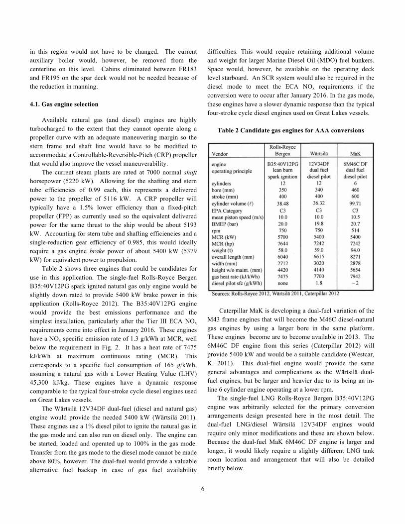
in this region would not have to be changed. The current auxiliary boiler would, however, be removed from the centerline on this level. Cabins eliminated between FR183 and FR195 on the spar deck would not be needed because of the reduction in manning. 4.1. Gas engine selection Available natural gas (and diesel) engines are highly turbocharged to the extent that they cannot operate along a propeller curve with an adequate maneuvering margin so the stern frame and shaft line would have to be modified to accommodate a Controllable-Reversible-Pitch (CRP) propeller that would also improve the vessel maneuverability. The current steam plants are rated at 7000 normal shaft horsepower (5220 kW). Allowing for the shafting and stern tube efficiencies of 0.99 each, this represents a delivered power to the propeller of 5116 kW. A CRP propeller will typically have a 1.5% lower efficiency than a fixed-pitch propeller (FPP) as currently used so the equivalent delivered power for the same thrust to the ship would be about 5193 kW. Accounting for stern tube and shafting efficiencies and a single-reduction gear efficiency of 0.985, this would ideally require a gas engine brake power of about 5400 kW (5379 kW) for equivalent power to propulsion. Table 2 shows three engines that could be candidates for use in this application. The single-fuel Rolls-Royce Bergen B35:40V12PG spark ignited natural gas only engine would be slightly down rated to provide 5400 kW brake power in this application (Rolls-Royce 2012). The B35:40V12PG engine would provide the best emissions performance and the simplest installation, particularly after the Tier III ECA NOx requirements come into effect in January 2016. These engines have a NOx specific emission rate of 1.3 g/kWh at MCR, well below the requirement in Fig. 2. It has a heat rate of 7475 kJ/kWh at maximum continuous rating (MCR). This corresponds to a specific fuel consumption of 165 g/kWh, assuming a natural gas with a Lower Heating Value (LHV) 45,300 kJ/kg. These engines have a dynamic response comparable to the typical four-stroke cycle diesel engines used on Great Lakes vessels. The Wärtsilä 12V34DF dual-fuel (diesel and natural gas) engine would provide the needed 5400 kW (Wärtsilä 2011). These engines use a 1% diesel pilot to ignite the natural gas in the gas mode and can also run on diesel only. The engine can be started, loaded and operated up to 100% in the gas mode. Transfer from the gas mode to the diesel mode cannot be made above 80%, however. The dual-fuel would provide a valuable alternative fuel backup in case of gas fuel availability
difficulties. This would require retaining additional volume and weight for larger Marine Diesel Oil (MDO) fuel bunkers. Space would, however, be available on the operating deck level starboard. An SCR system would also be required in the diesel mode to meet the ECA NOx requirements if the conversion were to occur after January 2016. In the gas mode, these engines have a slower dynamic response than the typical four-stroke cycle diesel engines used on Great Lakes vessels.
Table 2 Candidate gas engines for AAA conversions
Caterpillar MaK is developing a dual-fuel variation of the M43 frame engines that will become the M46C diesel-natural gas engines by using a larger bore in the same platform. These engines become are to become available in 2013. The 6M46C DF engine from this series (Caterpillar 2012) will provide 5400 kW and would be a suitable candidate (Westcar, K. 2011). This dual-fuel engine would provide the same general advantages and complications as the Wärtsilä dual-fuel engines, but be larger and heavier due to its being an in-line 6 cylinder engine operating at a lower rpm. The single-fuel LNG Rolls-Royce Bergen B35:40V12PG engine was arbitrarily selected for the primary conversion arrangements design presented here in the most detail. The dual-fuel LNG/diesel Wärtsilä 12V34DF engines would require only minor modifications and these are shown below. Because the dual-fuel MaK 6M46C DF engine is larger and longer, it would likely require a slightly different LNG tank room location and arrangement that will also be detailed briefly below.
7
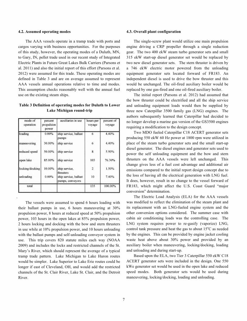
4.2. Assumed operating modes The AAA vessels operate in a tramp trade with ports and cargos varying with business opportunities. For the purposes of this study, however, the operating modes of a Duluth, MN, to Gary, IN, pellet trade used in our recent study of Integrated Electric Plants in Future Great Lakes Bulk Carriers (Parsons et al. 2011) and also the initial report of this effort (Parsons et al. 2012) were assumed for this trade. These operating modes are defined in Table 3 and are on average assumed to represent AAA vessels annual operations relative to time and modes. This assumption checks reasonably well with the annual fuel use on the existing steam ships. Table 3 Definition of operating modes for Duluth to Lower
Lake Michigan round-trip
. The vessels were assumed to spend 6 hours loading with their ballast pumps in use, 6 hours maneuvering at 30% propulsion power, 8 hours at reduced speed at 50% propulsion power, 103 hours in the open lakes at 85% propulsion power, 2 hours locking and docking with the bow and stern thrusters in use while at 10% propulsion power, and 10 hours unloading with the ballast pumps and self-unloading conveyor system in use. This trip covers 820 statute miles each way (NOAA 2009) and includes the locks and restricted channels of the St. Mary’s River, which should represent the average of a typical tramp trade pattern. Lake Michigan to Lake Huron routes would be simpler. Lake Superior to Lake Erie routes could be longer if east of Cleveland, OH, and would add the restricted channels of the St. Clair River, Lake St. Clair, and the Detroit River.
4.3. Overall plant configuration The single-screw plant would utilize one main propulsion engine driving a CRP propeller through a single reduction gear. The two 400 ekW steam turbo generator sets and small 315 ekW start-up diesel generator set would be replaced by two new diesel generator sets. The stern thruster is driven by a 746 ekW electric motor powered from the unloading equipment generator sets located forward of FR183. An independent diesel is used to drive the bow thruster and this would be unchanged. The oil-fired auxiliary boiler would be replaced by one gas-fired and one oil-fired auxiliary boiler. The initial report (Parsons et al. 2012) had assumed that the bow thruster could be electrified and all the ship service and unloading equipment loads would then be supplied by three new Caterpillar 3500 family gas (LNG) engines. The authors subsequently learned that Caterpillar had decided to no longer develop a marine gas version of the GS3500 engines requiring a modification to the design concept. Two MDO fueled Caterpillar C18 ACERT generator sets producing 550 ekW 60 Hz power at 1800 rpm were utilized in place of the steam turbo generator sets and the small start-up diesel generator. The diesel engines and generator sets used to power the self unloading equipment and the bow and stern thrusters on the AAA vessels were left unchanged. This change gives less of a fuel cost advantage and additional air emissions compared to the initial report design concept due to the loss of having all the electrical generation with LNG fuel. It does, however, result in no change to the vessel forward of FR183, which might affect the U.S. Coast Guard “major conversion” determination. The Electric Load Analysis (ELA) for the AAA vessels was modified to reflect the elimination of the steam plant and its replacement with an LNG-fueled engine system and the other conversion options considered. The summer case with cabin air conditioning loads was the controlling case. The LNG system requires power to re-gasify (vaporize) LNG, control tank pressure and heat the gas to about 15oC as needed by the engines. This can be provided by engine jacket cooling waste heat above about 30% power and provided by an auxiliary boiler when maneuvering, locking/docking, loading and unloading and during start-up. Based upon the ELA, two Tier 3 Caterpillar 550 ekW C18 ACERT generator sets were included in the design. One 550 kWe generator set would be used in the open lake and reduced speed modes. Both generator sets would be used during maneuvering, locking/docking, loading and unloading.
8
The LNG supply system is in accordance with International Maritime Organization (IMO), Det Norske Veritas (DNV) and American Bureau of Shipping (ABS) guidelines (IMO 2009, DNV 2012, ABS 2011). The LNG is supplied from port and starboard vertical LNG storage tanks located in separate LNG tank rooms between FR186 and FR193. The tanks are located the recommended B/5 from the side and B/15 from the bottom shell. The LNG tanks would be filled from port or starboard bunkering stations. Each tank is equipped with its own cold box containing the associated LNG re-gasification and tank pressure control systems. They supply the engine through separate and independent Gas Valve Units (GVU) located in separate containment vessels within the engine room. The existing LNG fuel guidelines (DNV 2012, ABS 2011) require that propulsion have redundant fuel sources. The ABS Guidelines Section 2, Part 5.1 states "i) The propulsion and auxiliary arrangements and fuel supply systems are to be arranged so that in the case of emergency shutdown of the fuel gas supply the propulsion and maneuvering capability, together with power for essential services, can be maintained. Under such a condition the remaining power is to be sufficient to provide for a speed of at least 7 knots or half of the design speed, whichever is the lesser” (ABS 2011). The dual-fuel engine LNG installations would meet this requirement by having the diesel fuel mode backup if there is a shutdown of the LNG supply system. However, even with two independent LNG storage tanks, cold boxes and supply paths, the single-fuel, single engine LNG installation would still use a common LNG supply line and header to the engine and, thus, not meet this requirement. Two LNG engines with a combining gear, each supplied by a separate Gas Valve Unit, or a single engine with an auxiliary take-home motor feeding a
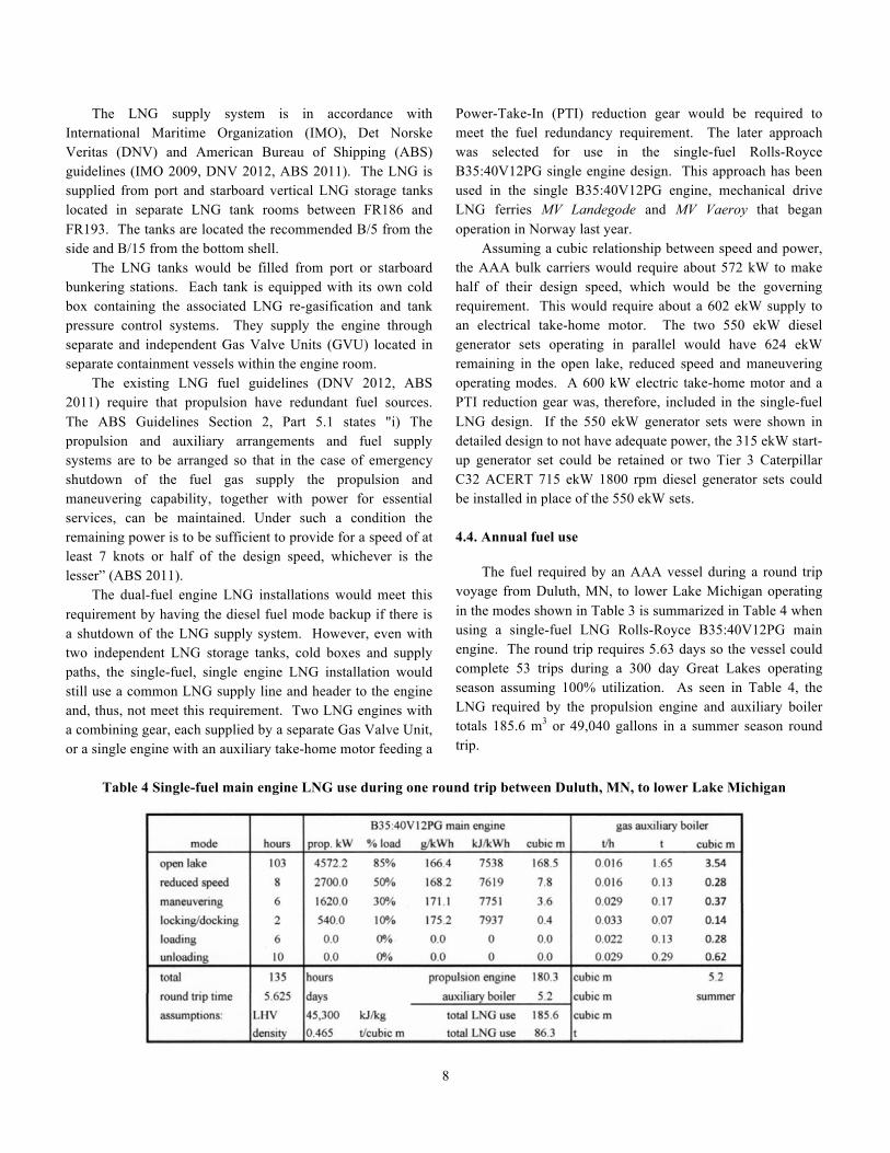
Power-Take-In (PTI) reduction gear would be required to meet the fuel redundancy requirement. The later approach was selected for use in the single-fuel Rolls-Royce B35:40V12PG single engine design. This approach has been used in the single B35:40V12PG engine, mechanical drive LNG ferries MV Landegode and MV Vaeroy that began operation in Norway last year. Assuming a cubic relationship between speed and power, the AAA bulk carriers would require about 572 kW to make half of their design speed, which would be the governing requirement. This would require about a 602 ekW supply to an electrical take-home motor. The two 550 ekW diesel generator sets operating in parallel would have 624 ekW remaining in the open lake, reduced speed and maneuvering operating modes. A 600 kW electric take-home motor and a PTI reduction gear was, therefore, included in the single-fuel LNG design. If the 550 ekW generator sets were shown in detailed design to not have adequate power, the 315 ekW start-up generator set could be retained or two Tier 3 Caterpillar C32 ACERT 715 ekW 1800 rpm diesel generator sets could be installed in place of the 550 ekW sets. 4.4. Annual fuel use The fuel required by an AAA vessel during a round trip voyage from Duluth, MN, to lower Lake Michigan operating in the modes shown in Table 3 is summarized in Table 4 when using a single-fuel LNG Rolls-Royce B35:40V12PG main engine. The round trip requires 5.63 days so the vessel could complete 53 trips during a 300 day Great Lakes operating season assuming 100% utilization. As seen in Table 4, the LNG required by the propulsion engine and auxiliary boiler totals 185.6 m3 or 49,040 gallons in a summer season round trip.
Table 4 Single-fuel main engine LNG use during one round trip between Duluth, MN, to lower Lake Michigan
9
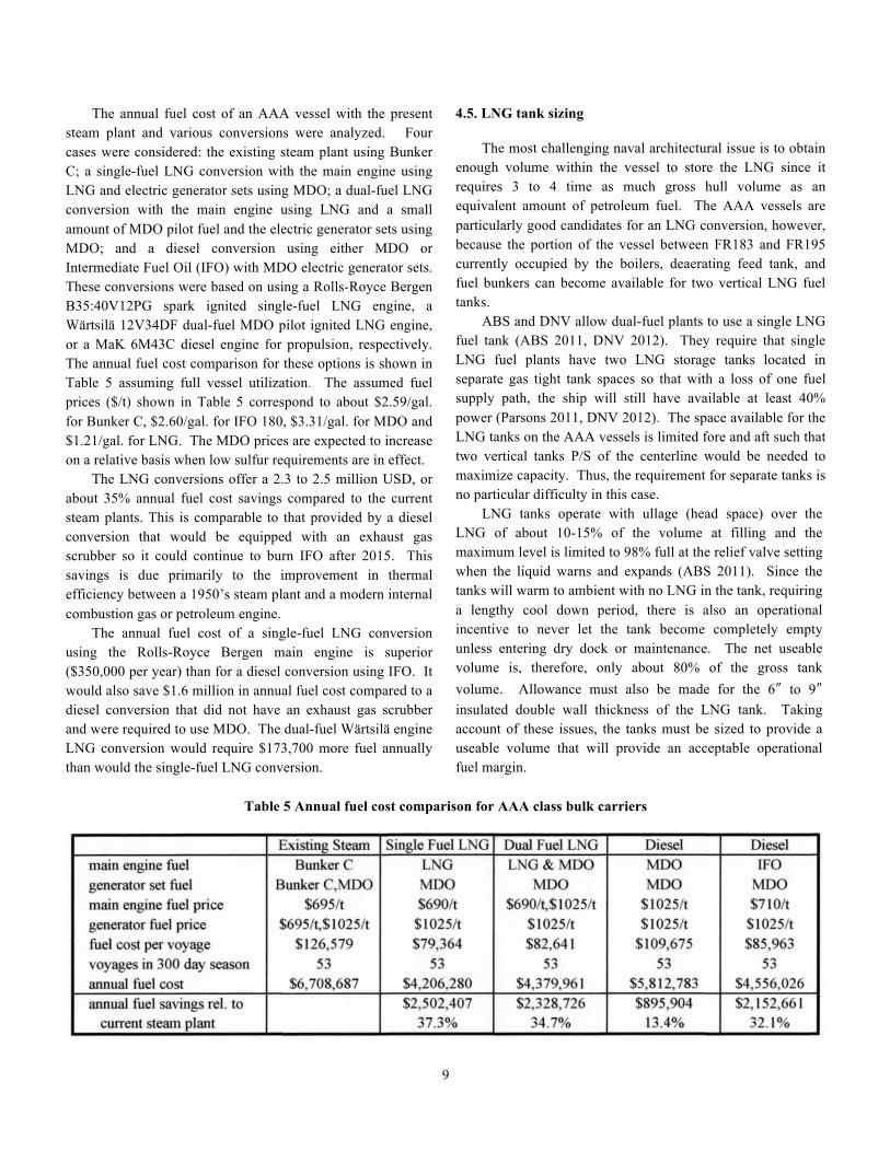
The annual fuel cost of an AAA vessel with the present steam plant and various conversions were analyzed. Four cases were considered: the existing steam plant using Bunker C; a single-fuel LNG conversion with the main engine using LNG and electric generator sets using MDO; a dual-fuel LNG conversion with the main engine using LNG and a small amount of MDO pilot fuel and the electric generator sets using MDO; and a diesel conversion using either MDO or Intermediate Fuel Oil (IFO) with MDO electric generator sets. These conversions were based on using a Rolls-Royce Bergen B35:40V12PG spark ignited single-fuel LNG engine, a Wärtsilä 12V34DF dual-fuel MDO pilot ignited LNG engine, or a MaK 6M43C diesel engine for propulsion, respectively. The annual fuel cost comparison for these options is shown in Table 5 assuming full vessel utilization. The assumed fuel prices ($/t) shown in Table 5 correspond to about $2.59/gal. for Bunker C, $2.60/gal. for IFO 180, $3.31/gal. for MDO and $1.21/gal. for LNG. The MDO prices are expected to increase on a relative basis when low sulfur requirements are in effect. The LNG conversions offer a 2.3 to 2.5 million USD, or about 35% annual fuel cost savings compared to the current steam plants. This is comparable to that provided by a diesel conversion that would be equipped with an exhaust gas scrubber so it could continue to burn IFO after 2015. This savings is due primarily to the improvement in thermal efficiency between a 1950’s steam plant and a modern internal combustion gas or petroleum engine. The annual fuel cost of a single-fuel LNG conversion using the Rolls-Royce Bergen main engine is superior ($350,000 per year) than for a diesel conversion using IFO. It would also save $1.6 million in annual fuel cost compared to a diesel conversion that did not have an exhaust gas scrubber and were required to use MDO. The dual-fuel Wärtsilä engine LNG conversion would require $173,700 more fuel annually than would the single-fuel LNG conversion.
4.5. LNG tank sizing The most challenging naval architectural issue is to obtain enough volume within the vessel to store the LNG since it requires 3 to 4 time as much gross hull volume as an equivalent amount of petroleum fuel. The AAA vessels are particularly good candidates for an LNG conversion, however, because the portion of the vessel between FR183 and FR195 currently occupied by the boilers, deaerating feed tank, and fuel bunkers can become available for two vertical LNG fuel tanks. ABS and DNV allow dual-fuel plants to use a single LNG fuel tank (ABS 2011, DNV 2012). They require that single LNG fuel plants have two LNG storage tanks located in separate gas tight tank spaces so that with a loss of one fuel supply path, the ship will still have available at least 40% power (Parsons 2011, DNV 2012). The space available for the LNG tanks on the AAA vessels is limited fore and aft such that two vertical tanks P/S of the centerline would be needed to maximize capacity. Thus, the requirement for separate tanks is no particular difficulty in this case. LNG tanks operate with ullage (head space) over the LNG of about 10-15% of the volume at filling and the maximum level is limited to 98% full at the relief valve setting when the liquid warns and expands (ABS 2011). Since the tanks will warm to ambient with no LNG in the tank, requiring a lengthy cool down period, there is also an operational incentive to never let the tank become completely empty unless entering dry dock or maintenance. The net useable volume is, therefore, only about 80% of the gross tank volume. Allowance must also be made for the 6ʺ″ to 9ʺ″ insulated double wall thickness of the LNG tank. Taking account of these issues, the tanks must be sized to provide a useable volume that will provide an acceptable operational fuel margin.
Table 5 Annual fuel cost comparison for AAA class bulk carriers
10
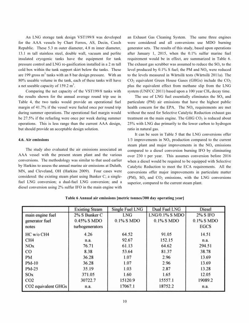
An LNG storage tank design VST199/8 was developed for the AAA vessels by Chart Ferrox, AS, Decin, Czech Republic. These 5.3 m outer diameter, 4.8 m inner diameter, 13.1 m tall stainless steel, double wall, vacuum and perlite insulated cryogenic tanks have the equipment for tank pressure control and LNG re-gasification installed in a 2 m tall cold box within the tank support skirt below the tanks. These are 199 gross m3 tanks with an 8 bar design pressure. With an 80% useable volume in the tank, each of these tanks will have a net useable capacity of 159.2 m3. Comparing the net capacity of the VST199/8 tanks with the results shown for the annual average round trip use in Table 4, the two tanks would provide an operational fuel margin of 41.7% if the vessel were fueled once per round trip during summer operations. The operational fuel margin would be 27.5% if the refueling were once per week during summer operations. This is less range than the current AAA design, but should provide an acceptable design solution. 4.6. Air emissions The study also evaluated the air emissions associated an AAA vessel with the present steam plant and the various conversions. The methodology was similar to that used earlier by Harkins to assess the annual marine air emissions at Duluth, MN, and Cleveland, OH (Harkins 2009). Four cases were considered: the existing steam plant using Bunker C; a single-fuel LNG conversion; a dual-fuel LNG conversion; and a diesel conversion using 2% sulfur IFO in the main engine with
an Exhaust Gas Cleaning System. The same three engines were considered and all conversions use MDO burning generator sets. The results of this study, based upon operations after January 1, 2015, when the 0.1% sulfur marine fuel requirement would be in effect, are summarized in Table 6. The exhaust gas scrubber was assumed to reduce the SOx to the level produced by 0.1% S fuel; the PM and NOx were reduced to the levels measured in Wärtsilä tests (Wärtsilä 2011a). The CO2 equivalent Green House Gases (GHGs) include the CO2 plus the equivalent effect from methane slip from the LNG system (UNFCC 2011) based upon a 100 year CH4 decay time. The use of LNG fuel essentially eliminates the SOx and particulate (PM) air emissions that have the highest public health concern for the EPA. The NOx requirements are met without the need for Selective Catalytic Reduction exhaust gas treatment on the main engine. The GHG CO2 is reduced about 25% with LNG due primarily to the lower carbon to hydrogen ratio in natural gas. It can be seen in Table 5 that the LNG conversions offer 1/3 improvements in NOx production compared to the current steam plant and major improvements in the NOx emissions compared to a diesel conversion burning IFO by eliminating over 230 t per year. This assumes conversion before 2016 when a diesel would be required to be equipped with Selective Catalytic Reduction to meet the ECA requirements. All the conversions offer major improvements in particulate matter (PM), SOx and CO2 emissions, with the LNG conversions superior, compared to the current steam plant.
Table 6 Annual air emissions [metric tonnes/300 day operating year]
11
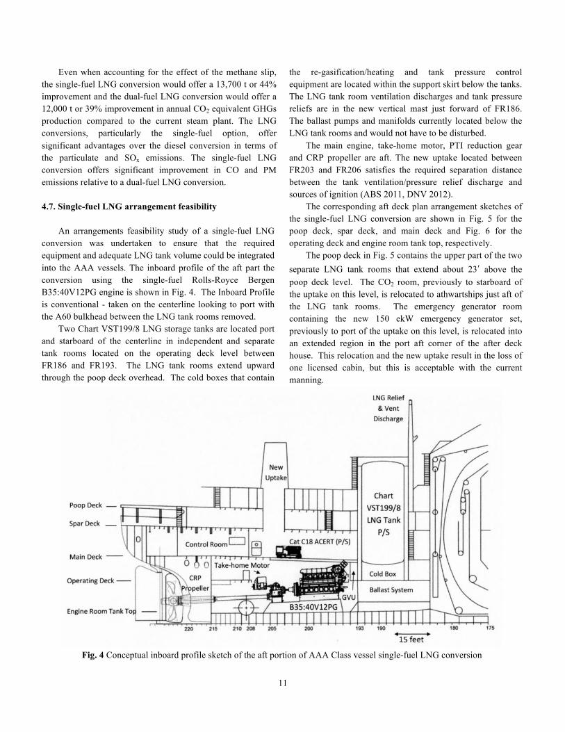
Even when accounting for the effect of the methane slip, the single-fuel LNG conversion would offer a 13,700 t or 44% improvement and the dual-fuel LNG conversion would offer a 12,000 t or 39% improvement in annual CO2 equivalent GHGs production compared to the current steam plant. The LNG conversions, particularly the single-fuel option, offer significant advantages over the diesel conversion in terms of the particulate and SOx emissions. The single-fuel LNG conversion offers significant improvement in CO and PM emissions relative to a dual-fuel LNG conversion. 4.7. Single-fuel LNG arrangement feasibility An arrangements feasibility study of a single-fuel LNG conversion was undertaken to ensure that the required equipment and adequate LNG tank volume could be integrated into the AAA vessels. The inboard profile of the aft part the conversion using the single-fuel Rolls-Royce Bergen B35:40V12PG engine is shown in Fig. 4. The Inboard Profile is conventional - taken on the centerline looking to port with the A60 bulkhead between the LNG tank rooms removed. Two Chart VST199/8 LNG storage tanks are located port and starboard of the centerline in independent and separate tank rooms located on the operating deck level between FR186 and FR193. The LNG tank rooms extend upward through the poop deck overhead. The cold boxes that contain
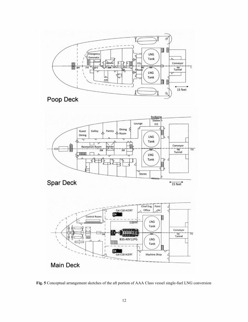
the re-gasification/heating and tank pressure control equipment are located within the support skirt below the tanks. The LNG tank room ventilation discharges and tank pressure reliefs are in the new vertical mast just forward of FR186. The ballast pumps and manifolds currently located below the LNG tank rooms and would not have to be disturbed. The main engine, take-home motor, PTI reduction gear and CRP propeller are aft. The new uptake located between FR203 and FR206 satisfies the required separation distance between the tank ventilation/pressure relief discharge and sources of ignition (ABS 2011, DNV 2012). The corresponding aft deck plan arrangement sketches of the single-fuel LNG conversion are shown in Fig. 5 for the poop deck, spar deck, and main deck and Fig. 6 for the operating deck and engine room tank top, respectively. The poop deck in Fig. 5 contains the upper part of the two separate LNG tank rooms that extend about 23ʹ′ above the poop deck level. The CO2 room, previously to starboard of the uptake on this level, is relocated to athwartships just aft of the LNG tank rooms. The emergency generator room containing the new 150 ekW emergency generator set, previously to port of the uptake on this level, is relocated into an extended region in the port aft corner of the after deck house. This relocation and the new uptake result in the loss of one licensed cabin, but this is acceptable with the current manning.
Fig. 4 Conceptual inboard profile sketch of the aft portion of AAA Class vessel single-fuel LNG conversion
12
Fig. 5 Conceptual arrangement sketches of the aft portion of AAA Class vessel single-fuel LNG conversion
13
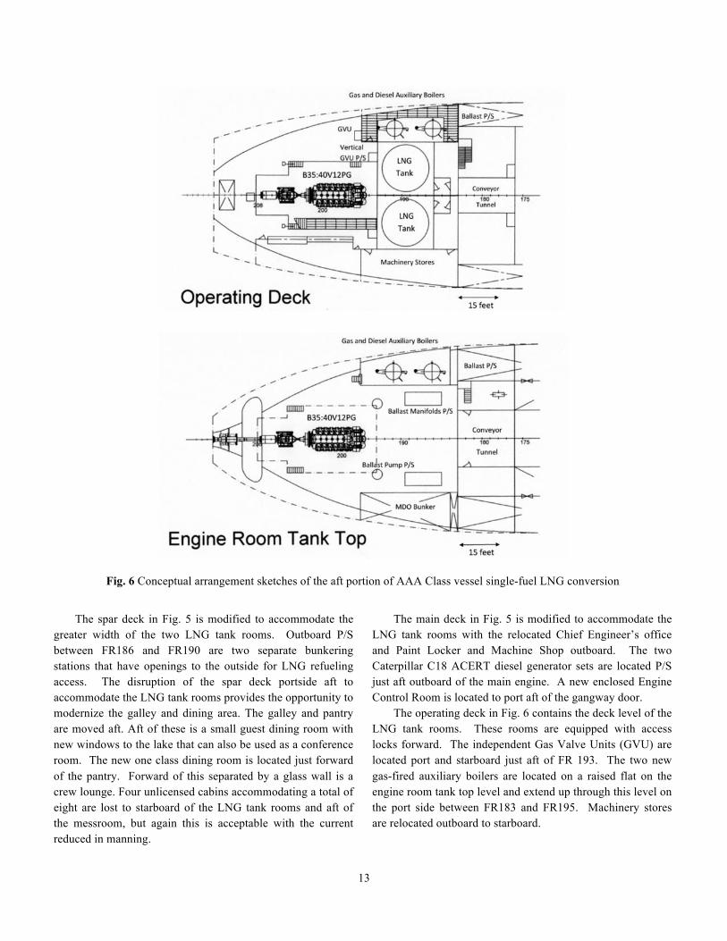
Fig. 6 Conceptual arrangement sketches of the aft portion of AAA Class vessel single-fuel LNG conversion
The spar deck in Fig. 5 is modified to accommodate the greater width of the two LNG tank rooms. Outboard P/S between FR186 and FR190 are two separate bunkering stations that have openings to the outside for LNG refueling access. The disruption of the spar deck portside aft to accommodate the LNG tank rooms provides the opportunity to modernize the galley and dining area. The galley and pantry are moved aft. Aft of these is a small guest dining room with new windows to the lake that can also be used as a conference room. The new one class dining room is located just forward of the pantry. Forward of this separated by a glass wall is a crew lounge. Four unlicensed cabins accommodating a total of eight are lost to starboard of the LNG tank rooms and aft of the messroom, but again this is acceptable with the current reduced in manning.
The main deck in Fig. 5 is modified to accommodate the LNG tank rooms with the relocated Chief Engineer’s office and Paint Locker and Machine Shop outboard. The two Caterpillar C18 ACERT diesel generator sets are located P/S just aft outboard of the main engine. A new enclosed Engine Control Room is located to port aft of the gangway door. The operating deck in Fig. 6 contains the deck level of the LNG tank rooms. These rooms are equipped with access locks forward. The independent Gas Valve Units (GVU) are located port and starboard just aft of FR 193. The two new gas-fired auxiliary boilers are located on a raised flat on the engine room tank top level and extend up through this level on the port side between FR183 and FR195. Machinery stores are relocated outboard to starboard.
14
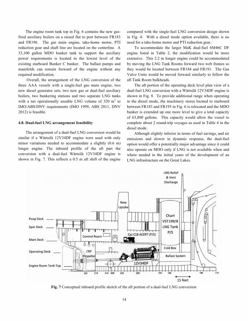
The engine room tank top in Fig. 6 contains the new gas-fired auxiliary boilers on a raised flat to port between FR183 and FR196. The gas main engine, take-home motor, PTI reduction gear and shaft line are located on the centerline. A 33,100 gallon MDO bunker tank to support the auxiliary power requirements is located in the lowest level of the existing starboard Bunker C bunker. The ballast pumps and manifolds can remain forward of the engine without any required modification. Overall, the arrangement of the LNG conversion of the three AAA vessels with a single-fuel gas main engine, two new diesel generator sets, two new gas or dual-fuel auxiliary boilers, two bunkering stations and two separate LNG tanks with a net operationally useable LNG volume of 320 m3 to IMO/ABS/DNV requirements (IMO 1999, ABS 2011, DNV 2012) is feasible. 4.8. Dual-fuel LNG arrangement feasibility The arrangement of a dual-fuel LNG conversion would be similar if a Wärtsilä 12V34DF engine were used with only minor variations needed to accommodate a slightly (0.6 m) longer engine. The inboard profile of the aft part the conversion with a dual-fuel Wärtsilä 12V34DF engine is shown in Fig. 7. This reflects a 0.5 m aft shift of the engine
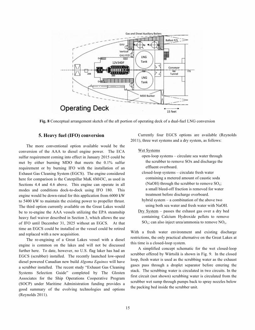
compared with the single-fuel LNG conversion design shown in Fig. 4. With a diesel mode option available, there is no need for a take-home motor and PTI reduction gear. To accommodate the larger MaK dual-fuel 6M46C DF engine listed in Table 2, the modification would be more extensive. This 2.2 m longer engine could be accommodated by moving the LNG Tank Rooms forward two web frames so they would be located between FR184 and FR191. The Gas Valve Units would be moved forward similarly to follow the aft Tank Room bulkheads. The aft portion of the operating deck level plan view of a dual-fuel LNG conversion with a Wärtsilä 12V34DF engine is shown in Fig. 8. To provide additional range when operating in the diesel mode, the machinery stores located to starboard between FR183 and FR195 in Fig. 6 is relocated and the MDO bunker is extended up one more level to give a total capacity of 63,800 gallons. This capacity would allow the vessel to complete about 2 round-trip voyages as used in Table 4 in the diesel mode. Although slightly inferior in terms of fuel savings, and air emissions and slower in dynamic response, the dual-fuel option would offer a potentially major advantage since it could also operate on MDO only if LNG is not available when and where needed in the initial years of the development of an LNG infrastructure on the Great Lakes.
Fig. 7 Conceptual inboard profile sketch of the aft portion of a dual-fuel LNG conversion
15
Fig. 8 Conceptual arrangement sketch of the aft portion of operating deck of a dual-fuel LNG conversion
5. Heavy fuel (IFO) conversion
The more conventional option available would be the conversion of the AAA to diesel engine power. The ECA sulfur requirement coming into effect in January 2015 could be met by either burning MDO that meets the 0.1% sulfur requirement or by burning IFO with the installation of an Exhaust Gas Cleaning System (EGCS). The engine considered here for comparison is the Caterpillar MaK 6M43C, as used in Sections 4.4 and 4.6 above. This engine can operate in all modes and conditions dock-to-dock using IFO 180. This engine would be down-rated for this application from 6000 kW to 5400 kW to maintain the existing power to propeller thrust. The third option currently available on the Great Lakes would be to re-engine the AAA vessels utilizing the EPA steamship heavy fuel waiver described in Section 3, which allows the use of IFO until December 31, 2025 without an EGCS. At that time an EGCS could be installed or the vessel could be retired and replaced with a new acquisition. The re-engining of a Great Lakes vessel with a diesel engine is common on the lakes and will not be discussed further here. To date, however, no U.S. flag laker has had an EGCS (scrubber) installed. The recently launched low-speed diesel powered Canadian new build Algoma Equinox will have a scrubber installed. The recent study “Exhaust Gas Cleaning Systems Selection Guide” completed by The Glosten Associates for the Ship Operations Cooperative Program (SOCP) under Maritime Administration funding provides a good summary of the evolving technologies and options (Reynolds 2011).
Currently four EGCS options are available (Reynolds 2011), three wet systems and a dry system, as follows:
Wet Systems open-loop systems – circulate sea water through the scrubber to remove SOx and discharge the effluent overboard. closed-loop systems – circulate fresh water containing a metered amount of caustic soda (NaOH) through the scrubber to remove SOx; a small bleed-off fraction is removed for water treatment before discharge overboard. hybrid system – a combination of the above two using both sea water and fresh water with NaOH. Dry System – passes the exhaust gas over a dry bed
containing Calcium Hydroxide pellets to remove SOx; can also inject urea/ammonia to remove NOx.
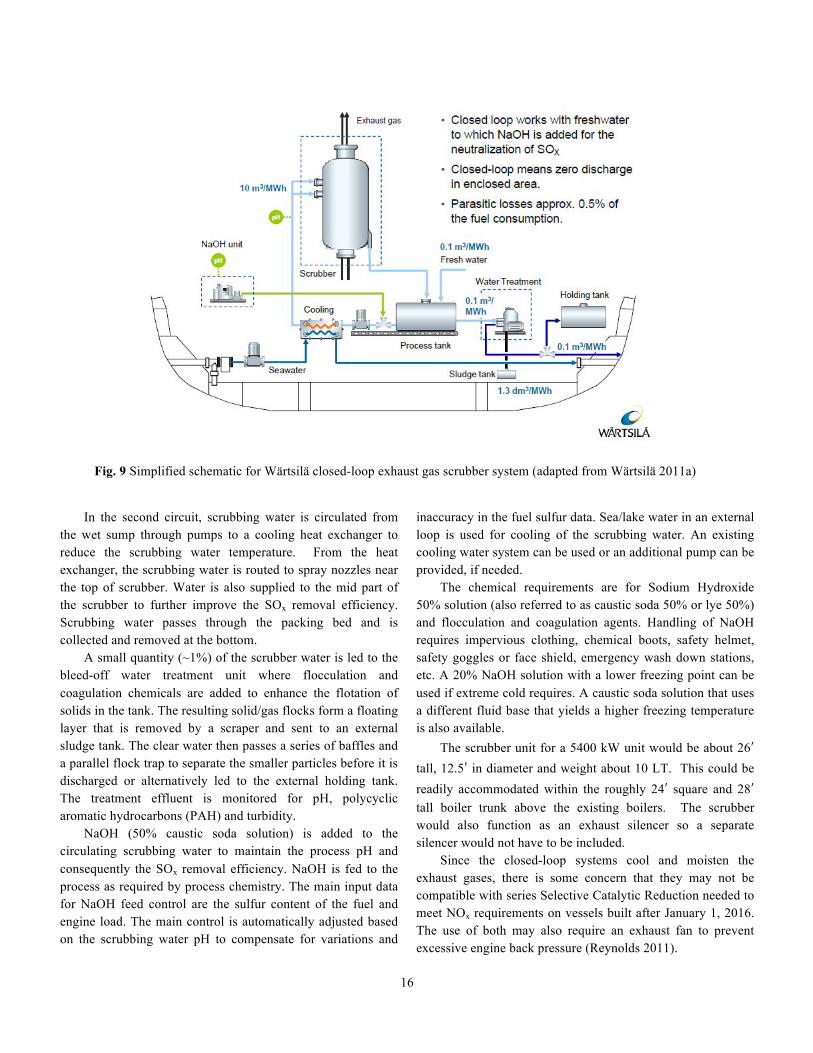
With a fresh water environment and existing discharge restrictions, the only practical alternative on the Great Lakes at this time is a closed-loop system. A simplified concept schematic for the wet closed-loop scrubber offered by Wärtsilä is shown in Fig. 9. In the closed loop, fresh water is used as the scrubbing water as the exhaust gases pass through a droplet separator before entering the stack. The scrubbing water is circulated in two circuits. In the first circuit (not shown) scrubbing water is circulated from the scrubber wet sump through pumps back to spray nozzles below the packing bed inside the scrubber unit.
16
Fig. 9 Simplified schematic for Wärtsilä closed-loop exhaust gas scrubber system (adapted from Wärtsilä 2011a)
In the second circuit, scrubbing water is circulated from the wet sump through pumps to a cooling heat exchanger to reduce the scrubbing water temperature. From the heat exchanger, the scrubbing water is routed to spray nozzles near the top of scrubber. Water is also supplied to the mid part of the scrubber to further improve the SOx removal efficiency. Scrubbing water passes through the packing bed and is collected and removed at the bottom. A small quantity (~1%) of the scrubber water is led to the bleed-off water treatment unit where flocculation and coagulation chemicals are added to enhance the flotation of solids in the tank. The resulting solid/gas flocks form a floating layer that is removed by a scraper and sent to an external sludge tank. The clear water then passes a series of baffles and a parallel flock trap to separate the smaller particles before it is discharged or alternatively led to the external holding tank. The treatment effluent is monitored for pH, polycyclic aromatic hydrocarbons (PAH) and turbidity. NaOH (50% caustic soda solution) is added to the circulating scrubbing water to maintain the process pH and consequently the SOx removal efficiency. NaOH is fed to the process as required by process chemistry. The main input data for NaOH feed control are the sulfur content of the fuel and engine load. The main control is automatically adjusted based on the scrubbing water pH to compensate for variations and
inaccuracy in the fuel sulfur data. Sea/lake water in an external loop is used for cooling of the scrubbing water. An existing cooling water system can be used or an additional pump can be provided, if needed. The chemical requirements are for Sodium Hydroxide 50% solution (also referred to as caustic soda 50% or lye 50%) and flocculation and coagulation agents. Handling of NaOH requires impervious clothing, chemical boots, safety helmet, safety goggles or face shield, emergency wash down stations, etc. A 20% NaOH solution with a lower freezing point can be used if extreme cold requires. A caustic soda solution that uses a different fluid base that yields a higher freezing temperature is also available. The scrubber unit for a 5400 kW unit would be about 26ʹ′ tall, 12.5ʹ′ in diameter and weight about 10 LT. This could be readily accommodated within the roughly 24ʹ′ square and 28ʹ′ tall boiler trunk above the existing boilers. The scrubber would also function as an exhaust silencer so a separate silencer would not have to be included. Since the closed-loop systems cool and moisten the exhaust gases, there is some concern that they may not be compatible with series Selective Catalytic Reduction needed to meet NOx requirements on vessels built after January 1, 2016. The use of both may also require an exhaust fan to prevent excessive engine back pressure (Reynolds 2011).
17
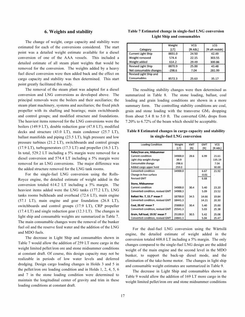
6. Weights and stability The change of weight, cargo capacity and stability were estimated for each of the conversions considered. The start point was a detailed weight estimate available for a diesel conversion of one of the AAA vessels. This included a detailed estimate of all steam plant weights that would be removed for the conversion. The weights added by a heavy fuel diesel conversion were then added back and the effect on cargo capacity and stability was then determined. This start point greatly facilitated this study. The removal of the steam plant was adapted for a diesel conversion and LNG conversions as developed above. The principal removals were the boilers and their auxiliaries; the steam plant machinery, systems and auxiliaries; the fixed pitch propeller with its shafting and bearings; main switchboards and control groups; and modified structure and foundations. The heaviest items removed for the LNG conversions were the boilers (149.9 LT), double reduction gear (47.8 LT), modified decks and structure (43.0 LT), main condenser (25.7 LT), ballast manifolds and piping (23.5 LT), high pressure and low pressure turbines (21.2 LT), switchboards and control groups (17.9 LT), turbogenerators (17.3 LT) and propeller (16.3 LT). In total, 529.2 LT including a 5% margin were removed for a diesel conversion and 574.4 LT including a 5% margin were removed for an LNG conversions. The major difference was the added structure removed for the LNG tank rooms. For the single-fuel LNG conversion using the Rolls-Royce engine, the detailed estimate of weight added in the conversion totaled 614.2 LT including a 5% margin. The heaviest items added were the LNG tanks (177.2 LT), LNG tanks rooms bulkheads and overhead (72.6 LT), main engine (57.1 LT), main engine and gear foundation (26.8 LT), switchboards and control groups (17.9 LT), CRP propeller (17.4 LT) and single reduction gear (12.3 LT). The changes in light ship and consumable weights are summarized in Table 7. The main consumable changes were the removal of the bunker fuel oil and the reserve feed water and the addition of the LNG and MDO fuels. The decrease in Light Ship and consumables shown in Table 7 would allow the addition of 259 LT more cargo in the weight limited pellet/iron ore and stone midsummer conditions at constant draft. Of course, this design capacity may not be realizable in periods of low water levels and deferred dredging. Design cargo loading changes in Holds 3 and 5 in the pellet/iron ore loading condition and in Holds 1, 2, 4, 5, 6 and 7 in the stone loading condition were determined to maintain the longitudinal center of gravity and trim in these loading conditions at constant draft.
Table 7 Estimated change in single-fuel LNG conversion Light Ship and consumables
The resulting stability changes were then determined as summarized in Table 8. The stone loading, ballast, coal loading and grain loading conditions are shown in a more summary form. The controlling stability conditions are coal, grain and stone loading with the transverse GMT dropping from about 5.4 ft to 5.0 ft. The converted GMT drops from 7.20% to 6.72% of the beam which should be acceptable. Table 8 Estimated changes in cargo capacity and stability
in single-fuel LNG conversion
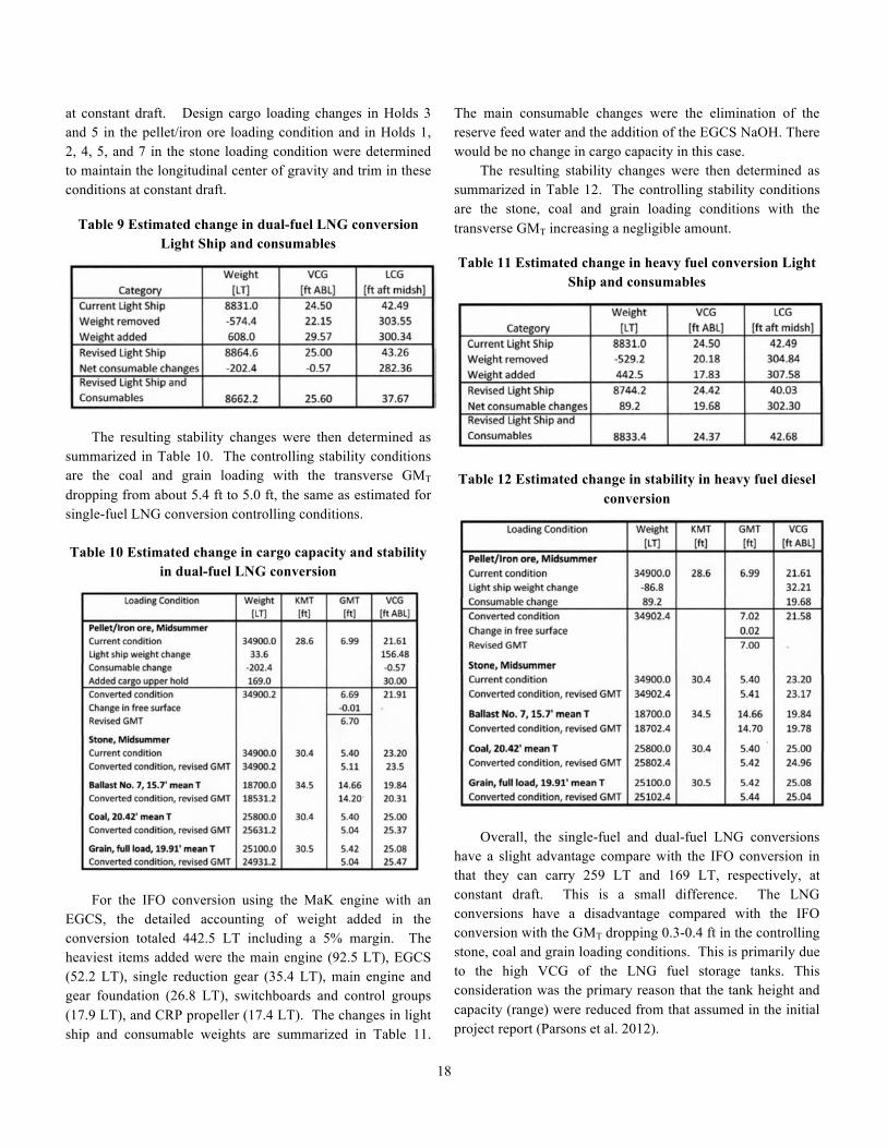
For the dual-fuel LNG conversion using the Wärtsilä engine, the detailed estimate of weight added in the conversion totaled 608.0 LT including a 5% margin. The only changes compared to the single-fuel LNG design are the added weight of the main engine and the second level in the MDO bunker, to support the back-up diesel mode, and the elimination of the take-home motor. The changes in light ship and consumable weight estimates are summarized in Table 9. The decrease in Light Ship and consumables shown in Table 9 would allow the addition of 169 LT more cargo in the weight limited pellet/iron ore and stone midsummer conditions
18
at constant draft. Design cargo loading changes in Holds 3 and 5 in the pellet/iron ore loading condition and in Holds 1, 2, 4, 5, and 7 in the stone loading condition were determined to maintain the longitudinal center of gravity and trim in these conditions at constant draft.
Table 9 Estimated change in dual-fuel LNG conversion Light Ship and consumables
The resulting stability changes were then determined as summarized in Table 10. The controlling stability conditions are the coal and grain loading with the transverse GMT dropping from about 5.4 ft to 5.0 ft, the same as estimated for single-fuel LNG conversion controlling conditions. Table 10 Estimated change in cargo capacity and stability
in dual-fuel LNG conversion
For the IFO conversion using the MaK engine with an EGCS, the detailed accounting of weight added in the conversion totaled 442.5 LT including a 5% margin. The heaviest items added were the main engine (92.5 LT), EGCS (52.2 LT), single reduction gear (35.4 LT), main engine and gear foundation (26.8 LT), switchboards and control groups (17.9 LT), and CRP propeller (17.4 LT). The changes in light ship and consumable weights are summarized in Table 11.
The main consumable changes were the elimination of the reserve feed water and the addition of the EGCS NaOH. There would be no change in cargo capacity in this case. The resulting stability changes were then determined as summarized in Table 12. The controlling stability conditions are the stone, coal and grain loading conditions with the transverse GMT increasing a negligible amount. Table 11 Estimated change in heavy fuel conversion Light
Ship and consumables
Table 12 Estimated change in stability in heavy fuel diesel conversion
Overall, the single-fuel and dual-fuel LNG conversions have a slight advantage compare with the IFO conversion in that they can carry 259 LT and 169 LT, respectively, at constant draft. This is a small difference. The LNG conversions have a disadvantage compared with the IFO conversion with the GMT dropping 0.3-0.4 ft in the controlling stone, coal and grain loading conditions. This is primarily due to the high VCG of the LNG fuel storage tanks. This consideration was the primary reason that the tank height and capacity (range) were reduced from that assumed in the initial project report (Parsons et al. 2012).
19
7. Shipyard considerations and planning The conversion of a Great Lakes Steamship to any of the three engine configurations will require the vessel to be removed from service for a nominal period of 26 weeks. There can be some give and take to this time period. However, to responsibly manage costs, the vessel needs to be out of service for a period that promotes a logical and efficient progression. The typical winter layup period for most Great Lakes cargo vessels is based on their particular economic need, the closure of the lock at Sault Ste Marie and the harshness of ice in any particular winter. To that end, planning the conversion to coincide with winter layup minimizes the number of sailing days lost on an annual basis. Typically, the weather is more challenging to vessel operations late in the year (Nov / Dec) than in late spring or early summer. As such, commencing the six month conversion period in Nov /Dec affords a May / June sailing and makes a good argument from the ship owner’s perspective to avoid the late season weather. The shipyard contractor must also have facility space and the availability of resources reserved for the project.
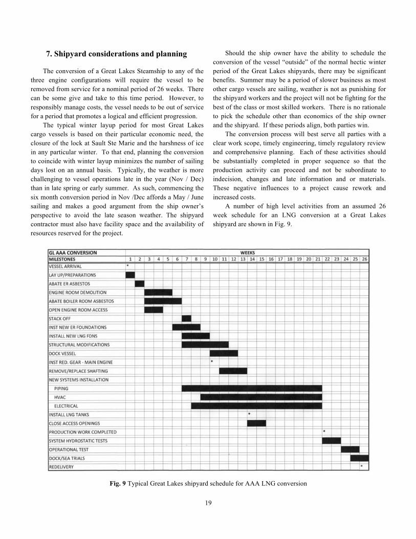
Should the ship owner have the ability to schedule the conversion of the vessel “outside” of the normal hectic winter period of the Great Lakes shipyards, there may be significant benefits. Summer may be a period of slower business as most other cargo vessels are sailing, weather is not as punishing for the shipyard workers and the project will not be fighting for the best of the class or most skilled workers. There is no rationale to pick the schedule other than economics of the ship owner and the shipyard. If these periods align, both parties win. The conversion process will best serve all parties with a clear work scope, timely engineering, timely regulatory review and comprehensive planning. Each of these activities should be substantially completed in proper sequence so that the production activity can proceed and not be subordinate to indecision, changes and late information and or materials. These negative influences to a project cause rework and increased costs. A number of high level activities from an assumed 26 week schedule for an LNG conversion at a Great Lakes shipyard are shown in Fig. 9.
Fig. 9 Typical Great Lakes shipyard schedule for AAA LNG conversion
20
Few activities within any schedule stand alone and most actions are interdependent with other schedule events. A few select “milestone” events within this schedule are highlighted (*) and may serve as payment events within the conversion contract. In contrast to many activities that may be difficult to determine when they start or finish, these milestone events are very clear. The proposed schedule does not identify the many production activities that should occur in advance of the vessel arrival. Examples of these types of activity include fabrication of structural foundations, piping modules, independent tanks, ladders, platforms, etc. A sequence of engineering, regulatory approval, material acquisition should all progress to allow fabrication and pre-outfitting activities in advance of the vessel layup. As soon as five weeks after arrival, the “old” engine room area should be clear down to the tank top level, this allowing some new installations to occur along with the removal process. With any project, and especially with this LNG initiative, a noble goal would be to have all production hot work complete one month prior to delivery. Notwithstanding which fuel application is used, LNG, LNG/MDO or IFO, hot work protocols must be followed. However, all parties will want to exercise an elevated level of caution with the new LNG fuel and the new equipment.
8. Capital cost estimate
8.1. Ships Work Breakdown Structure The estimate is based on work groups and accounts from the Ships Work Breakdown Structure (SWBS) format (NAVSEA 1985). SWBS is a tool to organize and manage costs of a large scale shipbuilding project such as this proposed conversion. Initially formulated for naval shipbuilding, SWBS now has worldwide use in commercial shipbuilding. The AAA conversion options all contain the same SWBS Groups, each having a three digest prefix as listed below, (first tier of cost summary). Additionally, various subordinate work activities included within each group are briefly described, (second tier of cost detail). The propulsion drive train for any vessel is a complex combination of machinery and control systems with one objective: an efficient and reliable propulsion system. The three options studied within this report have the same application rated output at the vessel’s propeller and each is configured with a single main engine. However, “upstream” and within the various engine applications, distinct differences do exist. Those variations and how they impact the price are
reviewed herein. The discussion follows the SWBS “Group” level categories of work and offers a general description of the work in italics and then in some detail, the differences for each application; single-fuel (SF) LNG; dual-fuel (DF) LNG/ MDO and IFO with EGCS equipment. 000 General - Administrative costs, warranty allowance. No variation among fuel applications noted. 100 Structure – Removal of vessel’s structure to allow access to engine room area, configuration of new bulkheads and decks, modifications to stack, structural openings such as doors, manholes and hatches, removal and replacement of foundations, anything pertaining to steelwork of any significance. The structural removal and stack relocation for the SF and DF applications are virtually identical. The paths to and from the engine and boiler rooms are vertical and will disrupt some aft deckhouse spaces. The location of the LNG tanks will cause substantially more work due to the fire boundary and separation requirements between the tanks. Additionally, the upper vertical extension of the tanks will cause relocation of several compartments with significant functions: CO2 room, emergency generator room, workshop, paint locker and Chief Engineer’s office. Moving these spaces also necessitates moving all the various utilities that serve these spaces: including ventilation, wiring, piping, outfit, insulation, etc. The IFO EGCS application does not require the structure modifications described above. All equipment is expected to occupy space no greater than what was used when the vessel sailed as a steamship. The scrubber tower is positioned in the relative position of where the silencer would have been located; hence no additional space or structural modifications are required. The IFO fuel application will require “space” for the fuel treatment equipment that is not required for the two LNG fuel applications. All three fuel applications will require modification to the stern post to allow withdrawal/installation of the CRP propeller system. 200 Propulsion – Removal of old engine room/boiler room equipment and piping systems and associated equipment. This includes installation of the main engine, reduction gear, CRP propeller and the mechanical and piping systems supporting their operation, i.e. sea water cooling, control air, exhaust, lube oil and waste oil. It also includes the exhaust gas scrubbing system for the IFO application only. This category has a high degree of similar work in that installing an engine, a reduction gear and a CRP propeller is
21
basically the same process. However, at this conceptual level it is difficult to get a good comparison on pricing for this amount of equipment. The vendors contacted were supportive with information and Rough Order of Magnitude (ROM) pricing, but, the lack of specificity on part of the perceived buyer led to price indications that must be viewed as a “range”. When one goes to actually buy a system, he or she will likely offer a Purchase Technical Specification (PTS) that will allow the scope to be clarified and the price to be presented within a quotation format. The EGCS system for the IFO application is included in this SWBS group. This type of equipment is not yet used on U.S. flag Great Lakes vessels; therefore, there is a lack of experience. The installation of the EGCS system, (based on the recommendation of the vendors) would add another 40-50% to the system costs. This level of cost, approximately $3M, is part of this group for the MaK IFO option. The shaft line is not expected to change during the conversion. To maintain the “old” line, the main engine and reduction gear foundations will need to fit within the vertical space between the shaft line and the ER tank top, after allowing for the height of the equipment from the base plates to the shaft lines. Any differences in shaft diameters are expected to be accommodated by new stern tube bearings. Detail engineering will verify if the existing vessel stern tube, length and diameter, will serve the new equipment. If not, other changes not part of this estimate are possible. 300 Electrical – Removal of obsolete electrical equipment and cables. This includes new electrical equipment such as generators, switchboards and motor control centers and or modification of existing units, electrical cable to serve any new consumers, lighting systems and generally the electrical control of all, including any new or modifications to the engine control room. The electrical supply and distribution system of any vessel is likely a core engine room function. Core, in the sense of power for the many consumers, some critical, and core, in the physical sense, by the location of generators and switchgear. In any of the conversions, the engine room will experience significant physical change. To that end, the estimate includes the replacement of the vessel’s switchboard and the Motor Control Centers (MCC). The decision to replace this equipment adds approximately $600K to the project. This does not affect the unloading equipment and stern thruster power supply that are located outside the engine room. There is a solid argument to suggest that this expense is small in nature to the overall scope of work and will provide savings and or fewer problems in the future.
Common to all three conversions is the installation of two new 550 ekW diesel fuel generator sets to replace the steam turbo generator sets and start-up generator set removed. 400 Electronics and Navigation – This includes main engine control systems, sensors and communication devices from the LNG handling and supply system, telephones, alarms, detection systems, and no electrical systems with significant voltage. This work group contains a machinery control system that supports an “Attended Engine Room” classification for all three fuel applications. It further contains an allowance of materials and labor to “communicate” with the LNG supply systems through sensors for many points, pressures, temperatures, flows, etc, in the SF and DF LNG applications. A new Fire Detection system is added for all three fuel applications. 500 Auxiliary Systems – This includes the engine room ventilation systems, separate LNG ventilation requirements, pipe insulation, spill containments, ER lifting devices, and many piping systems including, fire and general service, bilge, potable water, jacket water, compressed air, CRP hydraulic, fire extinguishing and the fuel system depending on the main engine application: LNG including LNG tanks, bunker stations, cold boxes, Gas Valve Units, etc.; MDO; and IFO. The various LNG tank and equipment packages posted a price range consensus between $3.5 and $4M. This equipment is all manufactured “offshore” and will carry appreciable delivery cost to the installing contractor. A typical LNG package will include: the two vertical insulated LNG storage tanks, an integrated cold box beneath each, two bunker stations, double walled piping for supply to the tanks, double walled pipe for supply downstream of the cold box, control system hardware and software, engineering and commissioning. The Gas Valve Units (GVU) are supplied by the main engine manufacturer in the DF case. As with the EGCS equipment, the Great Lakes shipyards do not yet have the experience with installing equipment of this nature. However, the skills required for installing do exist. Additional, separate ventilation is required for the LNG applications for all related spaces, the double walled piping, stack purging, and tank relief and venting. This work group also includes the fuel processing requirements for the IFO application. Absent the LNG equipment noted above, costs for fuel treatment; heaters, centrifuges, pumps, pipe insulation, etc, are included.
22
600 Outfit and Furnishings – This group covers the modifications to handrails, ladders, platforms, grating, painting and hull insulation, acoustical and/or to prevent the spread of fire. While each fuel application will require similar attention to those items that make the conversion “look good”, the difference in this category lies with the A-60 fire boundary for the LNG tank rooms. This rating is satisfied by the covering of the steel bulkheads, decks, etc. with approved insulation. The IFO conversion does not require any fire boundary separation between the ER and adjacent spaces. 800 Technical Support – Engineering, lofting, deadweight survey, classification fees, assessment surveys, etc. The “typical” Great Lakes steam to diesel repowering conversion has sufficient history that the technical activities are proven and established. It is anticipated that the LNG application will require additional effort on all fronts, engineering and regulatory input, and technical costs for the two LNG applications have been increased. 900 Shipyard Services – Those “support” functions to the production activities, including temporary HVAC, crane service, material handling, bilge and bunker cleaning, asbestos abatement, staging, etc. This group includes testing and trials. This group also includes charges for docking/undocking of the vessel and fees associated with the vessel while on dock. The many services that are provided to a vessel during an extended project can be significant. All three fuel applications will require similar attention. The differences within this
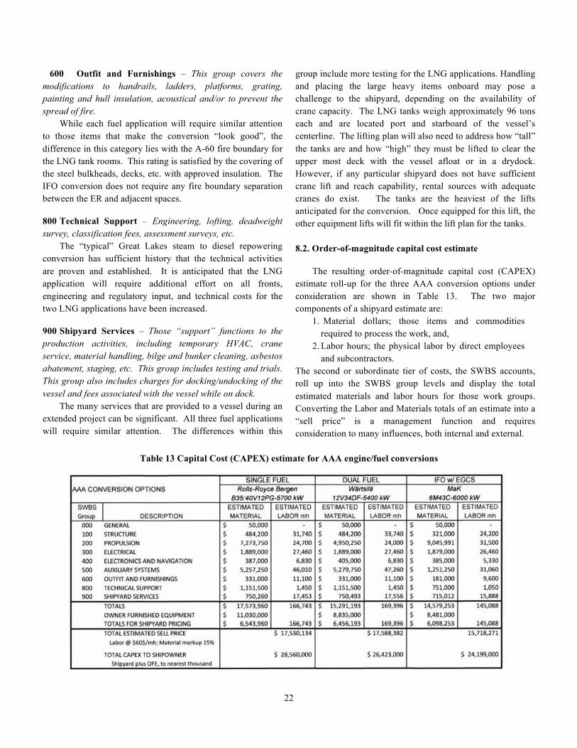
group include more testing for the LNG applications. Handling and placing the large heavy items onboard may pose a challenge to the shipyard, depending on the availability of crane capacity. The LNG tanks weigh approximately 96 tons each and are located port and starboard of the vessel’s centerline. The lifting plan will also need to address how “tall” the tanks are and how “high” they must be lifted to clear the upper most deck with the vessel afloat or in a drydock. However, if any particular shipyard does not have sufficient crane lift and reach capability, rental sources with adequate cranes do exist. The tanks are the heaviest of the lifts anticipated for the conversion. Once equipped for this lift, the other equipment lifts will fit within the lift plan for the tanks. 8.2. Order-of-magnitude capital cost estimate The resulting order-of-magnitude capital cost (CAPEX) estimate roll-up for the three AAA conversion options under consideration are shown in Table 13. The two major components of a shipyard estimate are:
1. Material dollars; those items and commodities required to process the work, and,
2. Labor hours; the physical labor by direct employees and subcontractors.
The second or subordinate tier of costs, the SWBS accounts, roll up into the SWBS group levels and display the total estimated materials and labor hours for those work groups. Converting the Labor and Materials totals of an estimate into a “sell price” is a management function and requires consideration to many influences, both internal and external.
Table 13 Capital Cost (CAPEX) estimate for AAA engine/fuel conversions
23
Any project of this complexity will be influenced by a large number of factors, including: schedule, design maturity, level of production engineering utilized, facility capability, workforce experience, clarity of regulations, etc. The goal is to make the influences more positive than negative, this by way of project management, a subject worthy of a separate paper. The many variables this project will experience, positive and less than positive, are not quantified here. For the sake of simplicity, the general range of published Labor and Material pricing, for likely Great Lakes Shipyard conversions, is used. Shipbuilder purchased materials are “marked up” 15% and labor is posted at $60 per hour. With these inputs, no additional allowances are included for overhead, profit, capital investment, etc. It is assumed these basic sell prices cover all costs, typical to what would be charged in a Time and Materials situation. Additionally, the nature of competitive bidding may cause shipyard pricing to be offered with “better rates”. Project type work that typically provides predictable and larger levels of labor hours may be priced more competitively, subject to management discretion. It should be noted that the owner of the vessel undergoing conversion will likely furnish the major equipment, thus removing the mark up costs associated with this “material”. For the sake of this example, “major equipment” is noted to be the following equipment:
a. Main propulsion engine and auxiliary components. In the case of the SF and DF conversions, this would include the Gas Valve Units.
b. Reduction gear and associated coolers, clutches, etc., c. Controllable Reversible Pitch propeller system with
OD box and miscellaneous equipment d. The LNG tanks, cold boxes, bunkering stations,
specialty piping and the control system. e. The two ship’s service generators. f. For the IFO application, the Exhaust Gas Cleaning
System equipment. g. Auxiliary boilers.
When equipment such as noted above is furnished by the owner to the shipyard, the responsibility for installing technicians, commissioning engineers and Original Equipment Manufacturer (OEM) warranties revert to the owner. Table 13 “removes” the cost of the major equipment items noted above from the shipyard responsibility. Other major material purchases may fit into the category of Owner Furnished Equipment (OFE) such as engineering, classification fees, etc; those purchases where the owner takes
the lead in arranging the product or service and subsequently, takes on the responsibility for the effective and timely performance of that vendor.
9. Remaining life-cycle economics A remaining life-cycle cost analysis was performed for each of the AAA conversion options assuming a converted vessel would have at least 15 years of useful service after conversion. As noted by Benford in his excellent introduction to engineering economics (Benford 2003), what matters in a design decision are the differences among the options. The assumption is made that all categories of savings, change in income and costs will be subject to the same inflation rate. In this case, the detailed annual cash flow in each category can be expressed in current (constant-value) dollars and a discount or interest rate can be applied to establish the Net Present Value (NPV) for the project (Benford 2003). The Net Present Value of a cash flow for a period of N=15 years and an interest rate i is given by, NPV(i,N) = CAPEX0 + 15 J
Σ Σ PW(i,n)*(Δcostjn,Δincomejn) (1) n=1 j=1
where n is the year index; j is the cost, savings or change in income category index; CAPEX0 is the capital cost of the conversion invested at year 0 and PW(i,n) is the single payment present worth factor for interest rate i and n years into the future. Costs are negative and savings and income are positive so a positive NPV indicates a sound investment. The N = 15 year cash flows were analyzed in detail for each year of the AAA vessel conversion options as a function of i. The following categories j were included in the analysis as applicable:
• Fuel cost (LNG, MDO, IFO) based upon the analysis summarized in Section 4.4. • Steamship fuel cost saved (Bunker C, MDO) based upon the analysis summarized in Section 4.4. • Lube oil cost based upon first principles and given specific use rates. • Steamship lube oil cost saved. • Scrubber NaOH, flocculent and coagulant cost based on published use rates and unit cost. • Maintenance cost. • Steamship maintenance cost saved. • Additional steamship fit-out and layup costs saved.
24
• Unlicensed boiler room crew cost saved. • Added income from additional cargo carried as detailed in Section 6. An average annual freight rate of $9.5/LT was assumed.
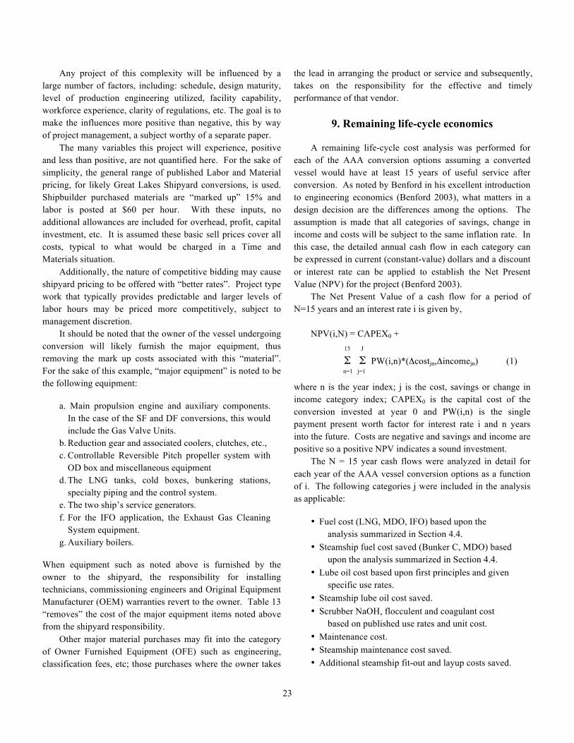
The LNG conversion maintenance costs were scaled based upon kW from the data used in the Washington State Ferry (WSF) analysis (Madsen 2011). It has been estimated that scrubber maintenance would require about half the time of one engineer (Reynolds 2011), but no additional crew were included in this analysis for this purpose. The elimination of the boilers would eliminate the need for three unlicensed oilers and this savings has been included. This, however, would not apply to the Cason J. Callaway since its oilers were eliminated when the boilers were automated (Bowler et. al 2002). The NPV for each of the AAA vessel conversion options is shown in Fig. 10 as a function of discount rate. Either of the LNG conversions is a sound investment for a discount rate up to about 11%. The single-fuel LNG conversion (solid line) is superior to the dual-fuel LNG conversion (long dashed line) economically. Both are superior to an IFO diesel engine conversion with an EGCS (short dashed line) over this entire range. If an owner elected to take advantage of the EPA Heavy Fuel waiver and defer the EGCS installation until 2025, this option (intermittent dash-dotted line) would be superior to the single-fuel LNG conversion above about 7% and above the dual-fuel LNG conversion above about 3%. A diesel conversion that uses MDO (medium dashed line) is significantly inferior to all other options considered.
Fig. 10 Net Present Value of various AAA conversions versus
discount rate
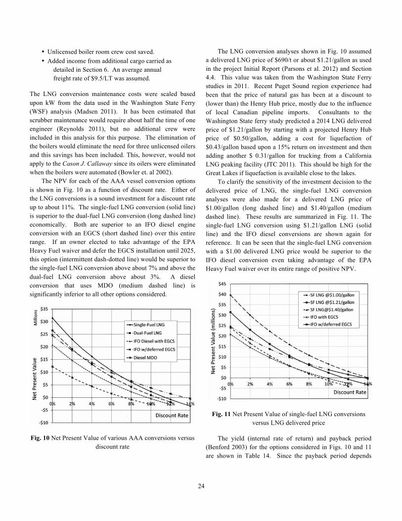
The LNG conversion analyses shown in Fig. 10 assumed a delivered LNG price of $690/t or about $1.21/gallon as used in the project Initial Report (Parsons et al. 2012) and Section 4.4. This value was taken from the Washington State Ferry studies in 2011. Recent Puget Sound region experience had been that the price of natural gas has been at a discount to (lower than) the Henry Hub price, mostly due to the influence of local Canadian pipeline imports. Consultants to the Washington State ferry study predicted a 2014 LNG delivered price of $1.21/gallon by starting with a projected Henry Hub price of $0.50/gallon, adding a cost for liquefaction of $0.43/gallon based upon a 15% return on investment and then adding another $ 0.31/gallon for trucking from a California LNG peaking facility (JTC 2011). This should be high for the Great Lakes if liquefaction is available close to the lakes. To clarify the sensitivity of the investment decision to the delivered price of LNG, the single-fuel LNG conversion analyses were also made for a delivered LNG price of $1.00/gallon (long dashed line) and $1.40/gallon (medium dashed line). These results are summarized in Fig. 11. The single-fuel LNG conversion using $1.21/gallon LNG (solid line) and the IFO diesel conversions are shown again for reference. It can be seen that the single-fuel LNG conversion with a $1.00 delivered LNG price would be superior to the IFO diesel conversion even taking advantage of the EPA Heavy Fuel waiver over its entire range of positive NPV.
Fig. 11 Net Present Value of single-fuel LNG conversions versus LNG delivered price
The yield (internal rate of return) and payback period (Benford 2003) for the options considered in Figs. 10 and 11 are shown in Table 14. Since the payback period depends
25
upon the discount rate, the value for a zero discount rate is shown in this table. Table 14 Yield and zero discount rate payback period for
AAA conversion options
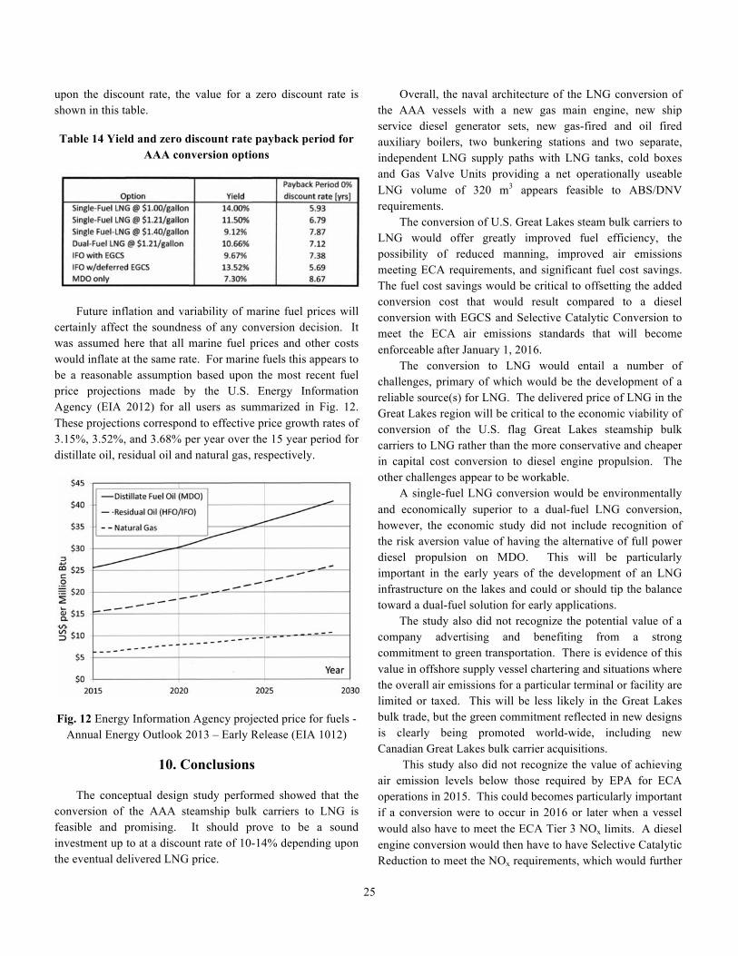
Future inflation and variability of marine fuel prices will certainly affect the soundness of any conversion decision. It was assumed here that all marine fuel prices and other costs would inflate at the same rate. For marine fuels this appears to be a reasonable assumption based upon the most recent fuel price projections made by the U.S. Energy Information Agency (EIA 2012) for all users as summarized in Fig. 12. These projections correspond to effective price growth rates of 3.15%, 3.52%, and 3.68% per year over the 15 year period for distillate oil, residual oil and natural gas, respectively.
Fig. 12 Energy Information Agency projected price for fuels -Annual Energy Outlook 2013 – Early Release (EIA 1012)
10. Conclusions The conceptual design study performed showed that the conversion of the AAA steamship bulk carriers to LNG is feasible and promising. It should prove to be a sound investment up to at a discount rate of 10-14% depending upon the eventual delivered LNG price.
Overall, the naval architecture of the LNG conversion of the AAA vessels with a new gas main engine, new ship service diesel generator sets, new gas-fired and oil fired auxiliary boilers, two bunkering stations and two separate, independent LNG supply paths with LNG tanks, cold boxes and Gas Valve Units providing a net operationally useable LNG volume of 320 m3 appears feasible to ABS/DNV requirements. The conversion of U.S. Great Lakes steam bulk carriers to LNG would offer greatly improved fuel efficiency, the possibility of reduced manning, improved air emissions meeting ECA requirements, and significant fuel cost savings. The fuel cost savings would be critical to offsetting the added conversion cost that would result compared to a diesel conversion with EGCS and Selective Catalytic Conversion to meet the ECA air emissions standards that will become enforceable after January 1, 2016. The conversion to LNG would entail a number of challenges, primary of which would be the development of a reliable source(s) for LNG. The delivered price of LNG in the Great Lakes region will be critical to the economic viability of conversion of the U.S. flag Great Lakes steamship bulk carriers to LNG rather than the more conservative and cheaper in capital cost conversion to diesel engine propulsion. The other challenges appear to be workable. A single-fuel LNG conversion would be environmentally and economically superior to a dual-fuel LNG conversion, however, the economic study did not include recognition of the risk aversion value of having the alternative of full power diesel propulsion on MDO. This will be particularly important in the early years of the development of an LNG infrastructure on the lakes and could or should tip the balance toward a dual-fuel solution for early applications. The study also did not recognize the potential value of a company advertising and benefiting from a strong commitment to green transportation. There is evidence of this value in offshore supply vessel chartering and situations where the overall air emissions for a particular terminal or facility are limited or taxed. This will be less likely in the Great Lakes bulk trade, but the green commitment reflected in new designs is clearly being promoted world-wide, including new Canadian Great Lakes bulk carrier acquisitions. This study also did not recognize the value of achieving air emission levels below those required by EPA for ECA operations in 2015. This could becomes particularly important if a conversion were to occur in 2016 or later when a vessel would also have to meet the ECA Tier 3 NOx limits. A diesel engine conversion would then have to have Selective Catalytic Reduction to meet the NOx requirements, which would further
26
add cost, weight, space requirements and potentially be in conflict with a closed-loop EGCS, if installed because an owner does not elect to take advantage of the EPA Heavy Fuel waiver. It remains ironic that the existence of the EPA Heavy Fuel waiver enabling an IFO diesel conversion without the need to install an EGCS until 2026 is a clear, significant disincentive to the use of the environmentally superior LNG.
Disclaimer
The opinions expressed here are those of the authors only and do not represent the opinions, conclusions, or plans of any of the companies that have provided assistance to this study. Annual fuel cost, air emissions and other economic results are developed by roll-up of more detailed estimates within spreadsheets so they contain more significant figures than justified. It is left to the reader to round-off to the level deemed appropriate.
Acknowledgements
This paper is a result of work sponsored by the Great Lakes Maritime Research Institute (GLMRI), a Consortium of the University of Wisconsin, Superior, and University of Minnesota, Duluth. This GLMRI study was funded through a Cooperative Agreement with the U. S. Maritime Administration (Cooperative Agreement #DTMA1H11002). This financial support is gratefully acknowledged. The authors would particularly like to acknowledge the assistance of Roy Bleiberg, American Bureau of Shipping, Houston, TX; Noel L. Bassett, American Steamship Co., Williamsville, NY; Leslee Hallas and Claus Emmer, Chart Industries, Inc., Garfield Heights, OH and Prior Lake, MN, respectively; Jan Kubica and Joris van Kreij, Chart Ferox, AS, Decin, Czech Republic; Michael Aasland, Marius Leisner, and Lars Petter Blikom, Det Norske Veritas, Hovik, Norway; Jan Fredrick Meling, Helge Vespestad and the other officers and crew of PSV Viking Princess, Eidesvik Offshore, Bomlo, Norway; Rolf Fiskerstrand and Ronny Kristiansen, Fiskerstrand Verft AS, Alesund, Norway; Oscar Bergheim and officers and crew of MV Raunefjord, Fjord1, Molde, Norway; Mark Barker, President, Interlake Steamship Co., Richfield, OH; Mitch Koslow, Keystone Shipping Co., Bala Cwnwyd, PA.; Oystein Djupvik and Peter Husoy, Kleven Verft AS, Ulsteinvik, Norway; Michael Hitt, Rolls-Royce, Mishicot, WI; Odd M. Horgen, Jakob Nielsen and Sindre Holmelid Haberg, Rolls-Royce, Bergen, Norway; Lee Seeley, Seeley Electric, Wellington, OH; Ken Westcar, Toromont Cat Power Systems,
Brampton, ONT; and John Hatley, Paul Glandt, Pete Jacobs, and Quentin Stewart, Wärtsilä North America, Inc., Houston, TX.
References
ABS 2011 Guide for propulsion and auxiliary systems for gas
fuelled ships, American Bureau of Shipping, Houston, May.
Benford, H. 2003 Engineering economics, Ch. 6 in Lamb, T. (ed.) Ship Design and Construction, SNAME, Jersey City, NJ, 6-1 – 6-35.
Bowler, G. R., Hartman, J. C., Sharrow, J. D. and Thibodeau, J. F., 2002, “Steam plant automation with bridge control on self-unloading bulk carrier Cason J. Calloway,” Great Lakes and Great Rivers Section of SNAME meeting, May 17.
Caterpillar 2008 M43C Project guide: propulsion, Caterpillar Marine Power Systems.
Caterpillar 2012 M46DF project guide - propulsion, Caterpillar Marine Power Systems, August.
DNV 2012 Gas fuelled engine installations, Rules for Classification of Ships/High Speed, Light Craft and Naval Surface Craft, Part 6, Chapter 13, Det Norske Veritas, Oslo, January.
EIA 2012 Annual energy outlook 2013 early release, U.S. Energy Information Administration, DOE/EIA-0383ER(2013), December 5.
EPA 2012 Great Lakes steamship repower incentive program, Federal Register, 77, 11, January 18.
Harkins, R. W. 2007 Great Lakes marine air emissions – we’re different up here! Marine Technology, 44, 3, 151-174.
IMO 2009 Interim guidelines on safety for natural gas-fuelled engine installations in ships, Resolution MSC.285 (86), June.
JTC 2011 Evaluating the use of liquefied natural gas in Washington state ferries, report prepared for the Joint Transportation Committee, Washington State, by the Cedar River Group and John Boylston, October.
Lloyd’s Register 2012 Classification news, No. 34/2012, 14 December.
Madsen, R. T. 2011 144-car ferry LNG conversion feasibility study: life cycle cost analysis, The Glosten Assoc., file no. 11030.01, 1 July.
NAVSEA 1985 Extended ship work breakdown structure (ESWBS), Vol. 1, NAVSEA S9040-AA-IDX-010/SWBS 5D, 13 Feb.
27
NOAA 2009 Distance between United States ports, U.S. Department of Commerce, NOAA (10th Edition).
Parsons, M. G., Singer, D. J. and Denomy, S. J. 2011 Integrated electric plants in future Great Lakes self-unloaders, Journal of Ship Production and Design, 27, 4, 169-185.
Parsons, M. G., O’Hern, P. J. and Denomy, S. J. 2012 The potential conversion of the U.S. Great Lakes steam bulk carriers to LNG propulsion – initial report, Journal of Ship Production and Design, 28, 3, 97-111.
Reynolds, K. J. 2011 Exhaust gas cleaning systems: selection guide, Glosten File No. 10047.01, 22 Feb. Rev. A, prepared for the Ship Operations Cooperative Program (SOCP).
Rolls-Royce 2011 Project guide Bergen engine type B fuel gas operation, Rolls-Royce Marine AS, Engines-Bergen.
Rolls-Royce 2012 Marine engine and propulsion programme 2102, Rolls-Royce Marine AS, Engines-Bergen.
UNFCC 2011 United Nations framework convention on climate change, http://unfcc.int/ghg_data/items/3825.
Wärtsilä 2011a SOx abatement solutions, Marine Club Seminar, Toronto, Canada, Wärtsilä Engines, January 22.
Wärtsilä 2011b Wärtsilä 34DF project guide, Wärtsilä Engines, March.
Westcar, K. 2012, private communication, Toromont Cat Power Systems, April 24, 2012.