Embed Size (px)
Citation preview
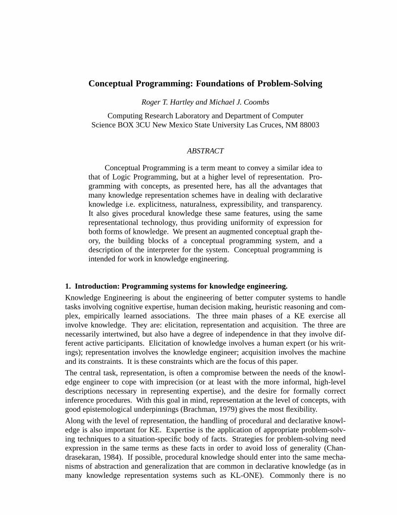
Conceptual Programming: Foundations of Problem-Solving
Roger T. Hartley and Michael J. Coombs
Computing Research Laboratory and Department of ComputerScience BOX 3CU New Mexico State University Las Cruces, NM 88003
ABSTRACT
Conceptual Programming is a term meant to convey a similar idea tothat of Logic Programming, but at a higher level of representation. Pro-gramming with concepts, as presented here, has all the advantages thatmany knowledge representation schemes have in dealing with declarativeknowledge i.e. explicitness, naturalness, expressibility, and transparency.It also gives procedural knowledge these same features, using the samerepresentational technology, thus providing uniformity of expression forboth forms of knowledge. We present an augmented conceptual graph the-ory, the building blocks of a conceptual programming system, and adescription of the interpreter for the system. Conceptual programming isintended for work in knowledge engineering.
1. Introduction: Programming systems for knowledge engineering.
Knowledge Engineering is about the engineering of better computer systems to handletasks involving cognitive expertise, human decision making, heuristic reasoning and com-plex, empirically learned associations. The three main phases of a KE exercise allinvolve knowledge. They are: elicitation, representation and acquisition. The three arenecessarily intertwined, but also have a degree of independence in that they inv olve dif-ferent active participants. Elicitation of knowledge involves a human expert (or his writ-ings); representation involves the knowledge engineer; acquisition involves the machineand its constraints. It is these constraints which are the focus of this paper.
The central task, representation, is often a compromise between the needs of the knowl-edge engineer to cope with imprecision (or at least with the more informal, high-leveldescriptions necessary in representing expertise), and the desire for formally correctinference procedures. With this goal in mind, representation at the level of concepts, withgood epistemological underpinnings (Brachman, 1979) gives the most flexibility.
Along with the level of representation, the handling of procedural and declarative knowl-edge is also important for KE. Expertise is the application of appropriate problem-solv-ing techniques to a situation-specific body of facts. Strategies for problem-solving needexpression in the same terms as these facts in order to avoid loss of generality (Chan-drasekaran, 1984). If possible, procedural knowledge should enter into the same mecha-nisms of abstraction and generalization that are common in declarative knowledge (as inmany knowledge representation systems such as KL-ONE). Commonly there is no
- 2 -
choice of strategy provided or strategies are expressed in a different language from therest of the knowledge base. This paper describes a uniform way of including proceduralknowledge and factual information in both the assertional and terminological componentsof the representation system. The paradigm behind these methods is calledconceptualprogramming.
Until a few years ago the best available tools for building expert systems were the‘‘empty’’ systems, typified by EMYCIN (van Melle, 1980). A spate of EMYCIN look-alikes are now commercially available (e.g. Teknowledge’s M1 and TI’s Personal Consul-tant). Expert system technology has become equated with the rule-based paradigm (syn-tactic pattern-matching, forward or back chaining), even though such systems have beencriticized for their methodological and technological shortcomings (Clancey, 1983; Hart-ley, 1984; Chandrasekaran, 1983). The reported inadequacies of these systems led to thedevelopment ofhybrid systems which include IntelliCorp’s KEE and Inference’s ART.Among the ‘‘goodies’’ they include are frames, rules, procedures, demons (or ‘‘active val-ues’’), viewpoints and truth maintenance, all in the same package. However, the mereprovision of facilities does not make it easier to build expert systems since there is pre-cious little help in choosing appropriately among them.
At the other end of the scale is Prolog, whose foundations are rooted in formal logic, thusgiving an extremely elegant system, but which turns out to be inefficient in execution (inits pure form) and limited in scope. In between these two extremes there are few expertsystem tools which are expressive enough for ease of use and applicability and yet haveformal underpinnings. A notable exception is Omega, best described as a descriptionlogic (Attardi et al., 1984) which caters for frame-like expression of declarative knowl-edge yet has a formally complete set of inference rules.
We might wish for a language system in which arbitrary expressions of knowledge can behandled, and yet the arbitrariness is restricted to capturing real relationships in the world,not in the methods and procedures used to manipulate them. We might hope that therewould be no Lisp code to write and no choice to be made between seemingly equivalentpieces of technology. It is partially this lack of orthogonality in the hybrid systems whichmakes them so hard to work with. Moreover, a system which explicitly separatesdomain-specific information from all other typesand in which everything that is notdomain-specific is minimized and formalized is preferable. Conceptual Programming(hereafter ‘CP’) is just such a system since it expresses the content of knowledge, bothdeclarative and procedural, using concepts, and its interpreter follows a formally correctmethodology based on hypothesis generation and testing.
2. Extended conceptual graphs and procedural knowledge
Conceptual graphs, as described in Conceptual Structures, express declarative knowledge.An assertionalmechanism built using such graphs would allow a collection of graphs torepresent a state of knowledge of an agent. If rules governing the assertion and de-asser-tion of graphs can be expressed within theterminologicalcomponent, then proceduralknowledge can also be incorporated. Sowa has actors behaving like functions embeddedwithin a graph to provide concept referents (i.e. for instantiation). Our extension allowsactors to be much more like ‘‘active concepts’’ which accept states as preconditions andev ents as triggers. Having been triggered, they assert states and enable further acts as by-products of their activity. These actors may be used to expresscausality, inv olving states
- 3 -
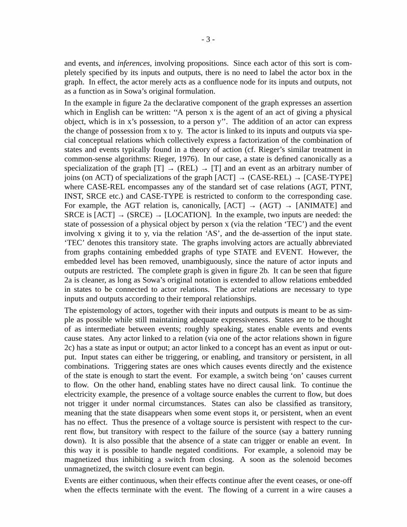
and events, andinferences, inv olving propositions. Since each actor of this sort is com-pletely specified by its inputs and outputs, there is no need to label the actor box in thegraph. In effect, the actor merely acts as a confluence node for its inputs and outputs, notas a function as in Sowa’s original formulation.
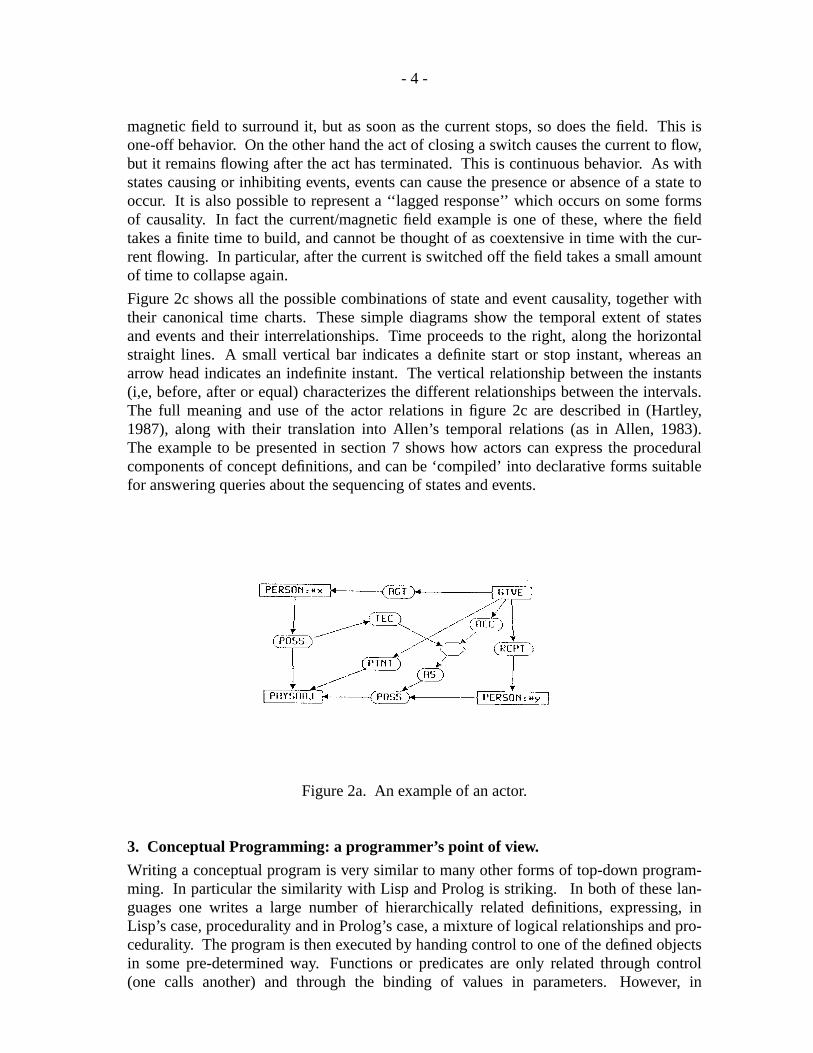
In the example in figure 2a the declarative component of the graph expresses an assertionwhich in English can be written: ‘‘A person x is the agent of an act of giving a physicalobject, which is in x’s possession, to a person y’’. The addition of an actor can expressthe change of possession from x to y. The actor is linked to its inputs and outputs via spe-cial conceptual relations which collectively express a factorization of the combination ofstates and events typically found in a theory of action (cf. Rieger’s similar treatment incommon-sense algorithms: Rieger, 1976). In our case, a state is defined canonically as aspecialization of the graph [T]→ (REL) → [T] and an event as an arbitrary number ofjoins (on ACT) of specializations of the graph [ACT]→ (CASE-REL)→ [CASE-TYPE]where CASE-REL encompasses any of the standard set of case relations (AGT, PTNT,INST, SRCE etc.) and CASE-TYPE is restricted to conform to the corresponding case.For example, the AGT relation is, canonically, [ACT]→ (AGT) → [ANIMATE] andSRCE is [ACT]→ (SRCE)→ [LOCATION]. In the example, two inputs are needed: thestate of possession of a physical object by person x (via the relation ‘TEC’) and the eventinvolving x giving it to y, via the relation ‘AS’, and the de-assertion of the input state.‘TEC’ denotes this transitory state. The graphs involving actors are actually abbreviatedfrom graphs containing embedded graphs of type STATE and EVENT. Howev er, theembedded level has been removed, unambiguously, since the nature of actor inputs andoutputs are restricted. The complete graph is given in figure 2b. It can be seen that figure2a is cleaner, as long as Sowa’s original notation is extended to allow relations embeddedin states to be connected to actor relations. The actor relations are necessary to typeinputs and outputs according to their temporal relationships.
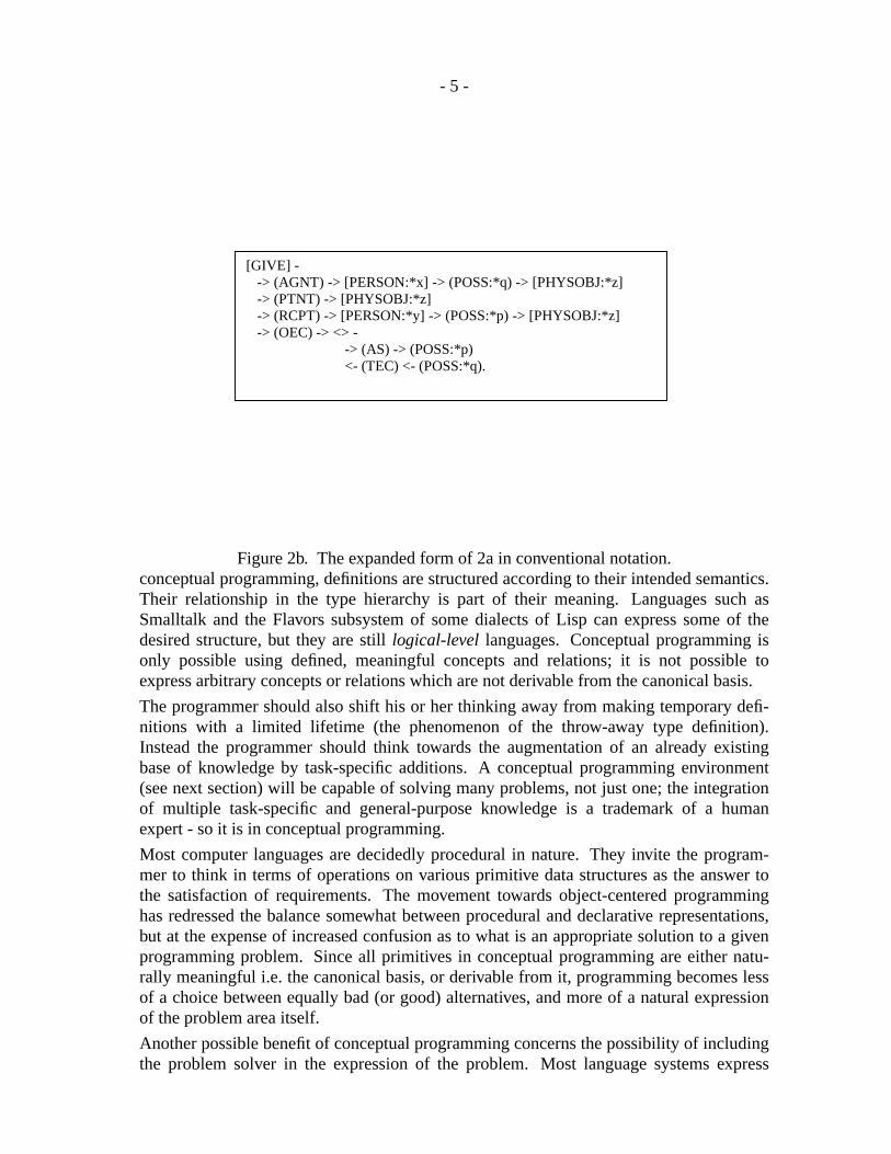
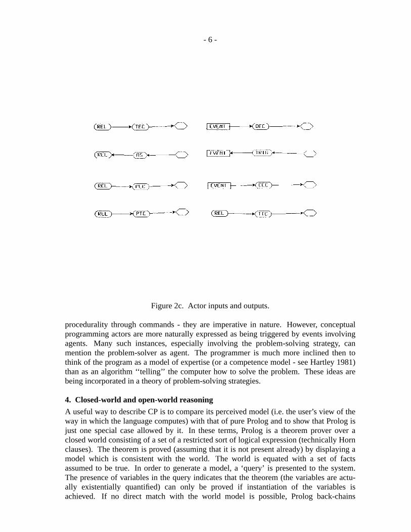
The epistemology of actors, together with their inputs and outputs is meant to be as sim-ple as possible while still maintaining adequate expressiveness. States are to be thoughtof as intermediate between events; roughly speaking, states enable events and eventscause states. Any actor linked to a relation (via one of the actor relations shown in figure2c) has a state as input or output; an actor linked to a concept has an event as input or out-put. Input states can either be triggering, or enabling, and transitory or persistent, in allcombinations. Triggering states are ones which causes events directly and the existenceof the state is enough to start the event. For example, a switch being ‘on’ causes currentto flow. On the other hand, enabling states have no direct causal link. To continue theelectricity example, the presence of a voltage source enables the current to flow, but doesnot trigger it under normal circumstances. States can also be classified as transitory,meaning that the state disappears when some event stops it, or persistent, when an eventhas no effect. Thus the presence of a voltage source is persistent with respect to the cur-rent flow, but transitory with respect to the failure of the source (say a battery runningdown). It is also possible that the absence of a state can trigger or enable an event. Inthis way it is possible to handle negated conditions. For example, a solenoid may bemagnetized thus inhibiting a switch from closing. A soon as the solenoid becomesunmagnetized, the switch closure event can begin.
Events are either continuous, when their effects continue after the event ceases, or one-offwhen the effects terminate with the event. The flowing of a current in a wire causes a
- 4 -
magnetic field to surround it, but as soon as the current stops, so does the field. This isone-off behavior. On the other hand the act of closing a switch causes the current to flow,but it remains flowing after the act has terminated. This is continuous behavior. As withstates causing or inhibiting events, events can cause the presence or absence of a state tooccur. It is also possible to represent a ‘‘lagged response’’ which occurs on some formsof causality. In fact the current/magnetic field example is one of these, where the fieldtakes a finite time to build, and cannot be thought of as coextensive in time with the cur-rent flowing. In particular, after the current is switched off the field takes a small amountof time to collapse again.
Figure 2c shows all the possible combinations of state and event causality, together withtheir canonical time charts. These simple diagrams show the temporal extent of statesand events and their interrelationships. Time proceeds to the right, along the horizontalstraight lines. A small vertical bar indicates a definite start or stop instant, whereas anarrow head indicates an indefinite instant. The vertical relationship between the instants(i,e, before, after or equal) characterizes the different relationships between the intervals.The full meaning and use of the actor relations in figure 2c are described in (Hartley,1987), along with their translation into Allen’s temporal relations (as in Allen, 1983).The example to be presented in section 7 shows how actors can express the proceduralcomponents of concept definitions, and can be ‘compiled’ into declarative forms suitablefor answering queries about the sequencing of states and events.
Figure 2a. An example of an actor.
3. Conceptual Programming: a programmer’s point of view.
Writing a conceptual program is very similar to many other forms of top-down program-ming. In particular the similarity with Lisp and Prolog is striking. In both of these lan-guages one writes a large number of hierarchically related definitions, expressing, inLisp’s case, procedurality and in Prolog’s case, a mixture of logical relationships and pro-cedurality. The program is then executed by handing control to one of the defined objectsin some pre-determined way. Functions or predicates are only related through control(one calls another) and through the binding of values in parameters. However, in
- 5 -
Figure 2b. The expanded form of 2a in conventional notation.conceptual programming, definitions are structured according to their intended semantics.Their relationship in the type hierarchy is part of their meaning. Languages such asSmalltalk and the Flavors subsystem of some dialects of Lisp can express some of thedesired structure, but they are stilllogical-level languages. Conceptual programming isonly possible using defined, meaningful concepts and relations; it is not possible toexpress arbitrary concepts or relations which are not derivable from the canonical basis.
The programmer should also shift his or her thinking away from making temporary defi-nitions with a limited lifetime (the phenomenon of the throw-away type definition).Instead the programmer should think towards the augmentation of an already existingbase of knowledge by task-specific additions. A conceptual programming environment(see next section) will be capable of solving many problems, not just one; the integrationof multiple task-specific and general-purpose knowledge is a trademark of a humanexpert - so it is in conceptual programming.
Most computer languages are decidedly procedural in nature. They invite the program-mer to think in terms of operations on various primitive data structures as the answer tothe satisfaction of requirements. The movement towards object-centered programminghas redressed the balance somewhat between procedural and declarative representations,but at the expense of increased confusion as to what is an appropriate solution to a givenprogramming problem. Since all primitives in conceptual programming are either natu-rally meaningful i.e. the canonical basis, or derivable from it, programming becomes lessof a choice between equally bad (or good) alternatives, and more of a natural expressionof the problem area itself.
Another possible benefit of conceptual programming concerns the possibility of includingthe problem solver in the expression of the problem. Most language systems express
[GIVE] - -> (AGNT) -> [PERSON:*x] -> (POSS:*q) -> [PHYSOBJ:*z] -> (PTNT) -> [PHYSOBJ:*z] -> (RCPT) -> [PERSON:*y] -> (POSS:*p) -> [PHYSOBJ:*z] -> (OEC) -> <> - -> (AS) -> (POSS:*p) <- (TEC) <- (POSS:*q).
- 6 -
Figure 2c. Actor inputs and outputs.
procedurality through commands - they are imperative in nature. However, conceptualprogramming actors are more naturally expressed as being triggered by events involvingagents. Many such instances, especially involving the problem-solving strategy, canmention the problem-solver as agent. The programmer is much more inclined then tothink of the program as a model of expertise (or a competence model - see Hartley 1981)than as an algorithm ‘‘telling’’ the computer how to solve the problem. These ideas arebeing incorporated in a theory of problem-solving strategies.
4. Closed-world and open-world reasoning
A useful way to describe CP is to compare its perceived model (i.e. the user’s view of theway in which the language computes) with that of pure Prolog and to show that Prolog isjust one special case allowed by it. In these terms, Prolog is a theorem prover over aclosed world consisting of a set of a restricted sort of logical expression (technically Hornclauses). The theorem is proved (assuming that it is not present already) by displaying amodel which is consistent with the world. The world is equated with a set of factsassumed to be true. In order to generate a model, a ‘query’ is presented to the system.The presence of variables in the query indicates that the theorem (the variables are actu-ally existentially quantified) can only be proved if instantiation of the variables isachieved. If no direct match with the world model is possible, Prolog back-chains
- 7 -
through a set of horn clauses (essentially implications) until either a match is achieved orfailure occurs. The set of instantiations forms the model which satisfies the query. Themere success of the back-chaining and matching procedure is sufficient grounds (in aclosed world) to state the query as a theorem. If no model was generated, then the‘negation as failure’ rule (again a consequence of the closed-world assumption) isgrounds to state the negation of the query as a theorem. ‘Resatisfaction’ may producealternative models, but these merely further support the theorem.
Open-world reasoning, on the other hand, is forced to relax these requirements andassumptions. Provability in a strict logical sense is impossible when both queries andconclusions can be questioned. To replace it a notion of ‘coherence’ is needed whichinvolves an evaluative procedure. The basic architecture of CP is however the same asthe Prolog case. We still have a query and still present it to the world for testing. Now,however, the query is subject to interpretation, according to alternative meanings of theterms used, as supplied through the their definitions in a schematic cluster. A query is anarbitrary proposition (just as in the Prolog case), but it may be of the form ‘assuming p1,p2, p3... is c?’ where the ps and c are all propositions. The world (or assertional compo-nent) consists of a set of independent propositions. They are not all assumed to be true(as in most logic-based systems), but only coherent when taken in appropriate subsets.The system needs a starting subset (the p’s in the query above) which provide an initialguess as to the appropriate context for c the query’s conclusion part. Further confirma-tion of disconfirmation of this guess is achieved through interpretation of the query. Theset of interpretations formcontextsin which the query makes sense. Since queries areoften incompletely specified or are ambiguous, a context needs to be established beforethe query can be answered.
The next step is to instantiate the alternative interpretations in an attempt to generatemodels which support the query. Models are alternative pictures of the real world gener-ated in accord with the constraints that the real world provides. The complexity of theform of these models is in stark contrast to the truth theoretic denotations of logicalexpressions in a closed-world system. All of these models may support the query in thesense that the query has in it a projection of the model. In this case the query may beasserted as a contingent fact and incorporated into the world (cf. Prolog’s rules). Notethat Prolog does not usually incorporate proved theorems into the system, although it iseasy to do so if required. The models may however contradict the query and formgrounds for asserting the negation of the query. Between these two extremes lie caseswhere some models support and some contradict the query. There must be therefore anevaluation carried out of the models in the light of the query to see whether there aregrounds for asserting the query, its negation or refining them further.
5. The components of a conceptual programming system
The conceptual programming environment consists of: aneditor, for program creationand modification; abrowseror inspector, for viewing the system’s parts and their rela-tionships; and aninterpreter, for execution. In fact, CP is being used as a test-bed forwork in model-generative reasoning, or MGR (Coombs, Hartley, 1987). A series of inter-preters incorporating these ideas is being implemented. The example to be presented insection 7 illustrates some of these ideas.
- 8 -
In conceptual programming, it is the editor’s job to maintain canonicality of definitions.It is better, therefore, to think of it as a knowledge acquisition utility for the terminologi-cal component. The notion here is similar to Nikl’s classifier, with the added constraintof canonicality (Schmolze and Lipkis, 1983).
There are many structures for the browser to keep track of. Firstly, the terminologicalcomponent needs to be displayed at coarse and fine levels of detail. This includes defini-tion through types and schematic clusters of concepts, relations and their procedural com-ponents. Second is the more problem-specific knowledge which changes through asser-tion and de-assertion, the assertional component. These are canonical graphs which con-tain specializations of type definitions joined in appropriate ways. They express some-thing like the episodic memory of the problem-solver, whereas the type hierarchy is anexpression of semantic or universal memory. Thirdly comes the representation of state i.ethe pattern of enabled and triggered actors. The browser can report on which actors havebeen triggered (the program trace) and which are partially or completely enabled but notyet triggered.
The interpreter for conceptual programs is the subject of the next section, but here it canbe said that its basic control mechanism is the conceptual join. Facts selected by the userare joined to the terminological component to produce interpretations (the contextsreferred to previously). The procedural content of these (from the actors built into defini-tions) formprograms. Prolog’s unifier is the logical-level counterpart of the conceptualjoin, but until Prolog accepts types (and semantic types, not just arbitrarily complex datastructures) it will remain as such.
In the area of debugging, conceptual programming has a potential advantage over conven-tional languages. instead of having to deal with low-level idiosyncracies of the language,the programmer can interact with the program at the level of the original problem formu-lation. the alteration of concept definitions is a much more meaningful activity then there-formulation of the implementation of an algorithm, or the tinkering with declara-tive/procedural specifications in either Prolog or a formal KR system.
6. Algorithms in the CP interpreter
CP is not a programming language in the normal sense. It does not compute with assign-ment to a store as in Pascal, Ada or Modula. nor does it use variable binding as in Lispand Prolog. All of these are logical-level languages in that they are epistemologicallyneutral. CP, howev er, is not neutral; it presents a particular view of how knowledge isbest represented and manipulated to perform tasks of problem-solving and reasoning.Conceptual graphs and their associated operations (join and project especially), togetherwith the CP routines for handling actors, form the logical-level underpinnings and can besaid to be the basis of computation.
At the epistemological level, computations based on these primitives are made on facts,contexts, definitions, procedural overlays, programs and models. all of these categories ofknowledge can be mapped to structures, all of which are conceptual graphs at base.Functionally speaking, the following four algorithms are involved:
interpret: A× D’ → C
proc-overlay: C× PO→ P
- 9 -
execute: P→ M
evaluate: M× F’ → E
The abbreviations denote sets of the epistemological entities as follows: A = assumptions,and A ⊂ F, the facts; D’⊂ D, the concept definitions; C = contexts; PO = proceduraloverlays; P = programs; M = models; F’⊂ F; E = explanations.
Although the implementation of these algorithms is variable, depending on the particularproblem-solving strategy employed, their specifications are currently as follows:
interpret:Join the assumption set to the set D of definitions, so that the number of concepts init that are covered by concepts in definitions is maximized and the excess conceptsin these definitions (i.e. not mentioned in A) is minimized. a join can be rejectedwhen either count is inadequate. The result of interpret is a set of contexts each cov-ering the assumption concepts with a mutually exclusive set of definitions. The wayin which interpret works is a major component of strategy.
proc-overlay:Each definition can have, in general, many procedural overlays, each representing adifferent type of strategic component. For each context, there may therefore be sev-eral programs. Selection may be made on the basis of a chosen strategy (e.g. onewhich mentions particular attributes or other concepts).
execute:Programs are essentially local rule-systems which express causality through a theoryof action similar in spirit to Rieger’s common-sense algorithms (Rieger, 1976) orany other sort of inference with the same epistemology. This means one involvingindependent, parallel actors, with typed pre- and post-conditions. The results of run-ning a program are models in which causal components are replaced by a program‘trace’ in the form of a time chart (cf. Dean and McDermott’s temporal data-base,1987).
evaluate:Since models contain more concepts than the initial set A, they can be supported orcontradicted by further facts. A join therefore between each model and the facts toachieve the same sort of cover as in interpret can determine the extent of this sup-port. Contradictory facts may support different models and thus be separately true,while being conjointly inconsistent.
7. Execution of a CP program
In order to illustrate the operation of a CP interpreter a simple example will be presented.Although it displays many of the features of the conceptual programming methodology, itis a closed-world example which can be programmed in Prolog. The crucial aspects ofopen-world programming i.e. the evaluation of the models generated from query interpre-tations and the revision of the query in the light of it is too long to display here.
The example concerns a fragment of knowledge about the nature of paint and whether ornot it will peel off a wet surface (the example is due to Mike Coombs). Only two types ofpaint will be represented: oil paint which does peel off and acrylic paint which does not,because it absorbs any surface water. Clearly there is scope here for uncertainty (how
- 10 -
much water can acrylic paint absorb? can oil paint tolerate a little moisture?) but this isnot handled in the example in order to keep it simple. The definitions and interpretationsare presented in graphical form since graphs are easier to read†.
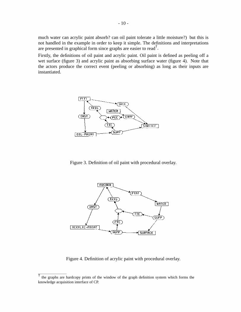
Firstly, the definitions of oil paint and acrylic paint. Oil paint is defined as peeling off awet surface (figure 3) and acrylic paint as absorbing surface water (figure 4). Note thatthe actors produce the correct event (peeling or absorbing) as long as their inputs areinstantiated.
Figure 3. Definition of oil paint with procedural overlay.
Figure 4. Definition of acrylic paint with procedural overlay.
† the graphs are hardcopy prints of the window of the graph definition system which forms theknowledge acquisition interface of CP.
- 11 -
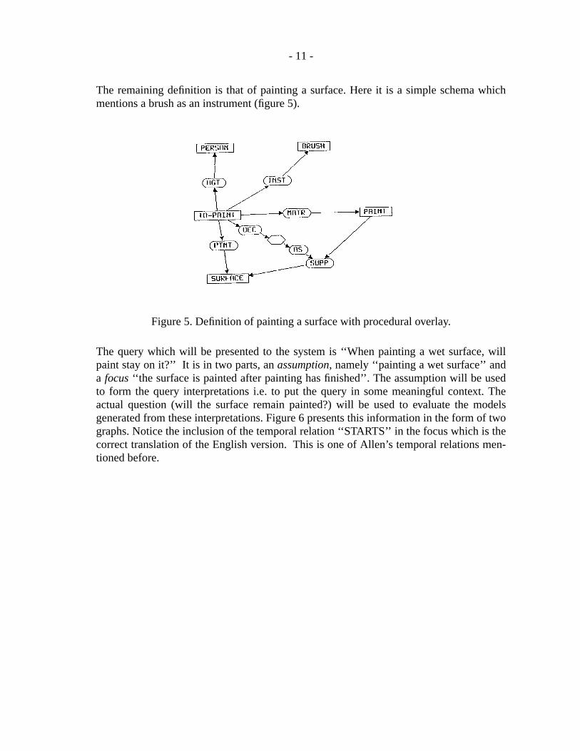
The remaining definition is that of painting a surface. Here it is a simple schema whichmentions a brush as an instrument (figure 5).
Figure 5. Definition of painting a surface with procedural overlay.
The query which will be presented to the system is ‘‘When painting a wet surface, willpaint stay on it?’’ It is in two parts, anassumption, namely ‘‘painting a wet surface’’ anda focus‘‘the surface is painted after painting has finished’’. The assumption will be usedto form the query interpretations i.e. to put the query in some meaningful context. Theactual question (will the surface remain painted?) will be used to evaluate the modelsgenerated from these interpretations. Figure 6 presents this information in the form of twographs. Notice the inclusion of the temporal relation ‘‘STARTS’’ in the focus which is thecorrect translation of the English version. This is one of Allen’s temporal relations men-tioned before.
- 12 -
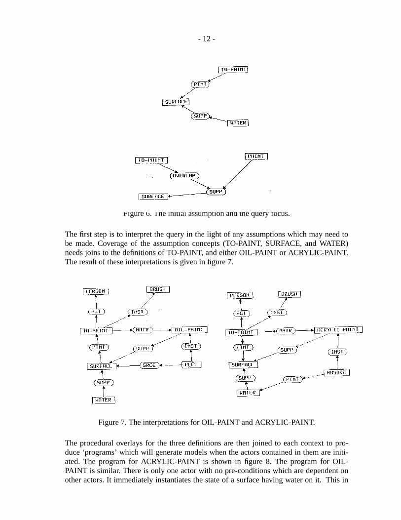
Figure 6. The initial assumption and the query focus.
The first step is to interpret the query in the light of any assumptions which may need tobe made. Coverage of the assumption concepts (TO-PAINT, SURFACE, and WATER)needs joins to the definitions of TO-PAINT, and either OIL-PAINT or ACRYLIC-PAINT.The result of these interpretations is given in figure 7.
Figure 7. The interpretations for OIL-PAINT and ACRYLIC-PAINT.
The procedural overlays for the three definitions are then joined to each context to pro-duce ‘programs’ which will generate models when the actors contained in them are initi-ated. The program for ACRYLIC-PAINT is shown in figure 8. The program for OIL-PAINT is similar. There is only one actor with no pre-conditions which are dependent onother actors. It immediately instantiates the state of a surface having water on it. This in
- 13 -
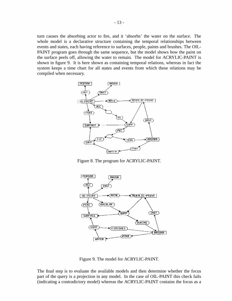
turn causes the absorbing actor to fire, and it ‘absorbs’ the water on the surface. Thewhole model is a declarative structure containing the temporal relationships betweenev ents and states, each having reference to surfaces, people, paints and brushes. The OIL-PAINT program goes through the same sequence, but the model shows how the paint onthe surface peels off, allowing the water to remain. The model for ACRYLIC-PAINT isshown in figure 9. It is here shown as containing temporal relations, whereas in fact thesystem keeps a time chart for all states and events from which these relations may becompiled when necessary.
Figure 8. The program for ACRYLIC-PAINT.
Figure 9. The model for ACRYLIC-PAINT.
The final step is to evaluate the available models and then determine whether the focuspart of the query is a projection in any model. In the case of OIL-PAINT this check fails(indicating a contradictory model) whereas the ACRYLIC-PAINT contains the focus as a
- 14 -
projection, thus indicating a supporting model.
Since there is at least one supported model, the answer to the user is ‘yes’, the justifica-tion being the existence of one explanation. (the ACRYLIC-PAINT model).
8. The implementation of conceptual programming
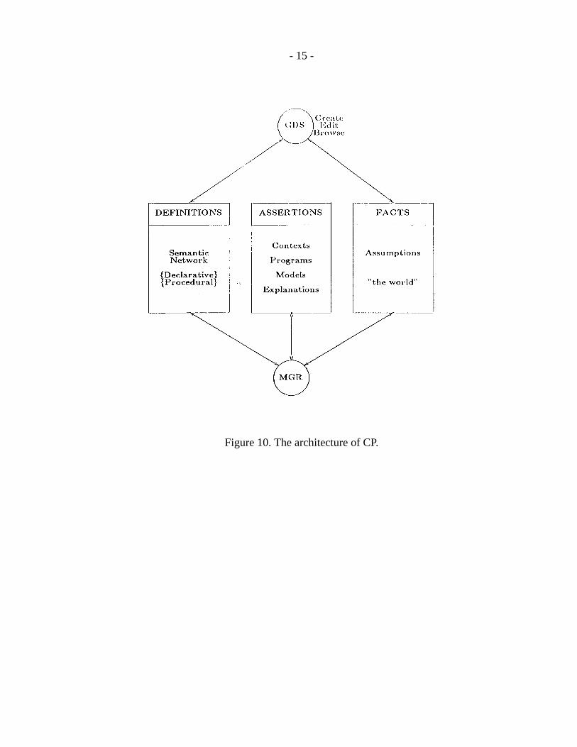
An implementation of the prototype conceptual programming system exists on a Symbol-ics 3670, in Symbolics Common Lisp. Its architecture is shown in figure 10. GDS is thegraph definition system, which enables the acquisition of facts, definitions, and procedu-ral overlays in graphical form. A sample window during one such session is shown infigure 11. Since the syntax of conceptual graphs (including our actor extensions) is well-defined, it is impossible to draw graphs which are syntactically incorrect. In order tofacilitate the acquisition and display of graphs too large for the screen, a method of over-laying graphs which have common nodes has been implemented. This also allows thedisplay of graphs generated through possibly multiple joins, without having to redrawmultiple graphs to produce a nice-looking display. GDS allows browsing of these struc-tures, their creation and modification. In addition, the semantic network can be browsed,in order to show what definitions are currently available. Definitions are bound to a par-ticular user and can be activated or de-activated selectively without the necessity of build-ing a physically separate knowledge base for each new application.
- 15 -
Figure 10. The architecture of CP.
- 16 -
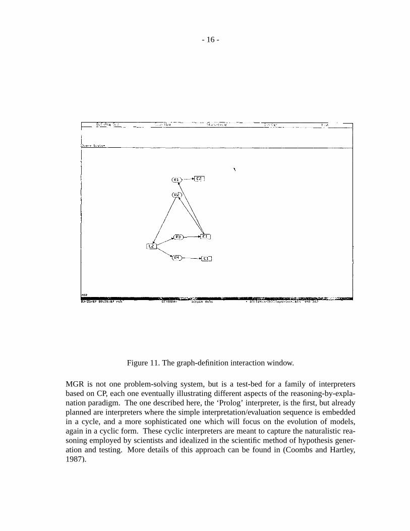
Figure 11. The graph-definition interaction window.
MGR is not one problem-solving system, but is a test-bed for a family of interpretersbased on CP, each one eventually illustrating different aspects of the reasoning-by-expla-nation paradigm. The one described here, the ‘Prolog’ interpreter, is the first, but alreadyplanned are interpreters where the simple interpretation/evaluation sequence is embeddedin a cycle, and a more sophisticated one which will focus on the evolution of models,again in a cyclic form. These cyclic interpreters are meant to capture the naturalistic rea-soning employed by scientists and idealized in the scientific method of hypothesis gener-ation and testing. More details of this approach can be found in (Coombs and Hartley,1987).
- 17 -
9. Conclusions
Conceptual programming is a methodology for engineering expert systems. Its underly-ing representation is conceptual graph theory, augmented to include inferential and state-change actors for procedural knowledge. Expert systems are seen as models of problem-solving including both task-specific and reflective modes of reasoning. The problem-solver can be modeled explicitly.
The conceptual programming environment includes a browser, editor, interpreter andexecution aids. It is designed to facilitate the complete production of an expert systemfrom requirements to validation.
Since actors can be defined at the same high level as declarative knowledge, and becomepart of the generalization hierarchy it is safe to envisage the system as having general pur-pose capabilities, as with standard procedural languages. The advantage is that conceptsmay be represented only fractionally below the level at which human beings think, andinconsistencies may be avoided through the constraints of canonicality, maintainedthrough well-defined graph operations.
10. References
Allen, J.F. (1983). Maintaining Knowledge about Temporal Intervals. Comm. ACM26(11), pp. 832-843.
Attardi, G., Corradini, A., De Cecco, M., and Simi, M. (1984). The Omega Primer. Tech.Report ESP/85/8, Delphi SpA.
Brachman, R.J. (1979). On the epistemological status of semantic networks. In Associa-tive Networks, N.V. Findler (Ed.), Academic Press: New York.
Chandrasekaran, B., (1984). Expert systems: Matching techniques to tasks. New YorkUniversity Symposium on Artificial Intelligence Applications for Business, 18-20,May 1983. also in Artificial Intelligence Applications for Business. Reitman, W.(Ed.) Ablex.
Clancey, W. J., (1983). The Advantages of Abstract Control Knowledge in Expert Systemdesign. Proceedings of the 3rd National Conference on Artificial Intelligence (Wash-ington, D.C.), pp. 74-78.
Dean, T.L., and McDermott, D.V. (1987). Temporal Data Base Management. AI Journal32(1).
Hartley, R.T. (1981). How expert should an expert system be? Proc. IJCAI-81, Vancou-ver, pp. 862-867, 1981.
Hartley, R.T. (1984). Expert Systems - A Conceptual Analysis. Int. J. of SystemsResearch and Information Technology, 1(1).
Hartley, R.T. (1985). Representation of procedural knowledge in expert systems. Proc. ofSecond IEEE conference on AI applications, Miami.
Hartley, R.T. (1987). Integrating theories of action and temporal relations for the CP envi-ronment. CRL monograph. XXXXXXX.
Rieger, Chuck. (1976). An Organization of Knowledge for Problem Solving and Lan-guage Comprehension. Artificial Intelligence 7, pp. 89-127.

- 18 -
Schmolze and Lipkis, (1983). Classification in the KL-ONE knowledge representationsystem. Proc. of IJCAI-83, pp. 330-332.
Sowa, J.F. (1984). Conceptual Structures. Reading, Mass.: Addison Wesley.
van Melle, W., (1980). System Aids in Constructing Consultation Programs. Ann Arbor,Michigan: UMI Research Press, 1981.